
VITLAB GmbH
Linus-Pauling-Str.1
63762 Grossostheim
Germany
tel: +49 6026 97799-0
fax: +49 6026 97799-30
www.vitlab.com
VITLAB®
Dispenser TA2
Instrucciones de manejo
Operating Manual
Dosificadores / Dispensers
Antes del primer uso enjuagar cuidadosamente
el aparato o desechar las primeras dosificacio-
nes.
Before using the instrument for the first time,
ensure it is rinsed carefully or discard the first
few samples dispensed.

2

3
Contenido
1. Normas de seguridad 4
2. Función y limitaciones de empleo 5
3. Campos de aplicación recomendados 6
4. Elementos de manejo 7
5. Primeros pasos 8
6. Purgar el aire 10
7. Dosificación 11
8. Accesorios 12
9. Límites de errores 14
10. Controlar el volumen (Calibrar) 15
11. Ajustar 16
12. Limpieza 17
13. Limpieza para análisis de trazas 18
14. Cambio de cánula de dosificación/ válvulas 19
15. Desmontaje del aparato 20
16. Referencias 21
17. Accesorios · Recambios 21
18. ¿Qué hacer en caso de avería? 24
19. Reparación · Service de calibración 25
20. Garantía 26
21. Eliminación 26

4
1. Normas de seguridad
Este aparato puede entrar en contacto con instalaciones, aplicaciones o materiales peligrosos. Estas instrucciones
de manejo no tienen por objeto enumerar todas las limitaciones de seguridad que pueden presentarse durante
el uso. El usuario del aparato tiene responsabilidad de tomar las medidas suficientes para su seguridad y su
salud, así como determinar las limitaciones de uso correspondientes antes de su utilización.
1. Todo usuario debe haber leído estas instruc-
ciones de manejo antes de utilizar el aparato y
debe seguirlas.
2. Observar las advertencias de peligro y las
reglas de seguridad generales, como por ejem-
plo utilizar vestimenta, protección de los ojos y
guantes de protección.
3. Observar las indicaciones del fabricante de los
reactivos.
4. Para la dosificación de medios inflamables,
tomar las medidas adecuadas para evitar
cargas electrostáticas, por ej. no dosificar en
recipientes de plástico, no frotar los aparatos
con un pano seco.
5. Utilizar el aparato únicamente para dosifi-
car líquidos observando estrictamente las
limitaciones de empleo y de uso. Observar las
excepciones de uso (véase pág. 5). En caso
de duda, dirigirse sin falta al fabricante o al
distribuidor.
6. Trabajar siempre de tal manera que no corran
peligro ni el operador ni otras personas. No
dirigir nunca la cánula de dosificación hacia
usted ni hacia otras personas al dosificar. Evi-
tar salpicaduras. Utilizar solamente recipientes
adecuados.
7. No desplazar nunca el émbolo hacia abajo la
cánula de dosificación estando colocada con la
caperuza a rosca.
8. No desenroscar nunca la cánula de dosifica-
ción, si está lleno el cilindro dosificador.
9. En la caperuza a rosca de la cánula de dosifica-
ción puede acumularse reactivo. Por lo tanto,
límpiela periódicamente.
10. Para frascos pequeños y en el caso de uso
del tubo de dosificación flexible, utilizar el
soporte, con objeto de evitar que se vuelque el
frasco.
11. No transportar nunca el aparato montado su-
jetándolo por la camisa del cilindro o el bloque
de válvulas. La rotura o el desprendimiento del
cilindro puede causar lesiones debidas a los
productos químicos (véase pág. 9, fig. 4).
12. No emplear nunca la fuerza. Siempre despla-
zar el émbolo suavemente hacia arriba y hacia
abajo.
13. Utilizar sólo accesorios y recambios originales.
No efectúe ninguna modificación técnica. ¡No
desmonte el aparato más allá de lo descrito en
las instrucciones de manejo!
14. Antes de cada uso, comprobar el estado
correcto de aparato. En el caso de que se pro-
duzcan averías en el aparato (por ej. desplaza-
miento difícil del émbolo, válvulas adheridas,
falta de hermeticidad), inmediatamente dejar
de dosificar, limpiar y seguir las instrucciones
del capítulo '¿Qué hacer en caso de avería?'
(véase pág. 24). En caso necesario dirigirse
al fabricante.
15. La unión roscada entre el bloque de la válvula
y el cilindro dosificador debe estar siempre
apretada firmemente.
16. El aparato no debe esterilizarse en autoclave.
2. Función y limitaciones de empleo
El dosificador acoplable a frasco VITLAB® Dispenser TA2 se emplea para la dosificación de líquidos directa-
mente desde el frasco de reserva.Los aparatos disponen de marcaje DE-M según los requisitos de la norma
DIN EN ISO 8655-5 y, opcionalmente, pueden equiparse con una válvula de purga SafetyPrime™. Cuando el
aparato es correctamente manipulado, el líquido dosificado entra solamente en contacto con los siguientes
materiales químicamente resistentes: diversos fluoroplásticos (ETFE, FEP, PFA, PCTFE, PTFE), zafiro Al2O3,
platino-iridio o tantalio, dependiendo del modelo (véase la identificación en la cánula de dosificación y en la
válvula de purga).
¡Rogamos lea este documento cuidadosamente!
!

5
Limitaciones de empleo
El aparato se emplea para dosificación de medios
teniendo en cuenta los siguientes límites físicos:
– Temperatura de empleo de +15 °C a +40 °C (de
59 °F a 104 °F) del aparato y del reactivo
– presión de vapor hasta max. 600 mbar. Por
encima de 300 mbares aspire lentamente para
evitar la ebullición del líquido.
– viscosidad cinemática hasta 500 mm2/s
(viscosidad dinámica [mPas] =
viscosidad cinemática [mm²/s]
x densidad [g/cm³])
– densidad: hasta 3,8 g/cm3
Limitaciones de uso
Los líquidos que hacen sedimentos pueden
provocan un desgaste en las juntas de émbolo o
pueden dificultar el movimiento del mismo, e in-
cluso bloquearlo (por ej. soluciones cristalizantes o
soluciones alcalinas concentradas). Si el émbolo se
moviera con dificultad, el aparato deberá limpiarse
de inmediato (pág. 17).
El VITLAB® Dispenser TA2 está concebido para
aplicaciones generales de laboratorio y cumple con
los requisitos de las normas correspondientes, p.
ej. de la norma DIN EN ISO 8655. El usuario mismo
tiene que comprobar la idoneidad del aparato para
su caso concreto de aplicaciones (por ej. análisis de
trazas, en el sector de alimentación etc.). No exis-
ten permisos para aplicaciones especiales por ej.
para la produción y administración de alimentos,
de productos farmaceuticos y cosméticos.
Excepciones de uso
VITLAB® Dispenser TA2
no utilizar con:
– líquidos que atacan zafiro Al2O3 o fluoroplásti-
cos como ETFE, FEP, PFA, PCTFA y PTFE (por ej.
Ácido de sodio disuelto*)
– líquidos que se descomponen al contacto con
platino-iridio o tantalio a través de un proceso
catalítico (por ej. H2O2). Atender al modelo de
aparato.
– solventes orgánicos
– tetrahidrofurano
– ácido trifluoroacético
– líquidos explosivos (por ej. sulfuro de carbono)
– suspensiones (por ej. de carbón activo) porque
las partículas sólidas pueden obstruir o dañar el
aparato
* Las soluciones de azida sódica son permi-
sibles sólo hasta un máximo de 0,1%.
Condiciones de almacenamiento
Almacene el aparato y los accesorios solamente en
lugares frescos y secos.
Temperatura de almacenamiento:
de -20 °C a +50 °C (de -4 °F a 122 °F).

6
3. Campos de aplicación recomendados
Elegir válvulas con resortes de platino-iridio o tantalio dependiendo del campo de aplicación.
El aparato puede utilizarse para dosificar los medios siguientes:
Medio a dosificar Resortes de válvulas:
Pt-Ir
Resortes de válvulas: Ta
Ácido acético + +
Ácido clorhídrico + +
Ácido fluorhídrico* + -
Ácido fosfórico + +
Ácido nítrico + +
Ácido perclórico + +
Ácido sulfúrico + +
Agua + +
Bromo + +
Hidróxido de sodio, 30 % + -
Peróxido de hidrógeno - +
Solución amoniacal + +
+ apropiado - no apropiado
Cánula de
dosificación
Esta tabla ha sido comprobada cuidadosamente y se basa en los conocimientos actuales. Observar siempre las instruc-
ciones de manejo del aparato y las indicaciones del fabricante de los reactivos. Además de los productos químicos
arriba mencionados pueden ser dosificados un gran número de soluciones salinas orgánicas e inorgánicas (por ej. reac-
tivos tampón biológicos), detergentes biológicos, así como medios para el cultivo de células. Si necesita informaciones
sobre sustancias químicas que no están mencionadas en la lista, por favor llámenos por teléfono. Edición: 0216/2
* Indicaciòn:
El ácido fluorhídrico ataca ligeramente al zafiro. Para reducir los valores de aluminio levemente elevados
recomendamos desechar antes del análisis 3-5 dosificaciones de 2 ml cada una.
Los compuestos que contienen fluoruros, como NaF, atacan el tantalio.

7
Llave de montaje
Tubo de aspiración Tubo de
dosificación inversa
Ajuste del volumen
Bloque de válvulas
(GL 45 filetage de flacon)
Válvula de purga
(opcional)
Caperuza a rosca
Tubo p. dosificación inver-
sa (opcional)
Tubo de aspiración
telescópico
Cánula de
dosificación
Anillo de retención
Cabeza del
émbolo
Unidad de dosificación
con número de serie
Manette de
la soupape de purge
Parties du boîtier
Flèche indicatrice
Logement du piston
4. Elementos de manejo
¡Atención!
El anillo de retención entre el bloque de la válvula y el cilindro
dosificador debe estar siempre apretado firmemente.

2
1
8
5.1 Contenido del embalaje
El embalaje contiene:
Dosificador acoplable a frasco VITLAB® Dispenser TA2, tubo de aspiración telescópico, cánula de dosifica-
ción o cánula de dosificación con válvula de purga y tubo para dosificación inversa (optativa para aparato
con válvula de purga), llave de montaje, tres adaptadores para frasco, un certificado de calidad y estas
instrucciones de manejo.
5.2 Puesta en marcha
1. Verifique el anillo de retención
Compruebe que el anillo de retención esté apretado firmemente
(fig. 1).
volumen nominal, ml adaptadores para
rosca de frasco
tubo de aspiración
longitud, mm
10 GL 28/ S 28 (ETFE), GL 32 (ETFE),
S 40 (PTFE)
125-240
2. Montaje del tubo de aspiración/ del tubo de dosificación
inversa
Monte y ajuste la longitud del tubo de aspiración telescópico de
acuerdo con la altura del frasco. Para evitar dañar la oliva coloque
el tubo de aspiración en el centro y con cuidado. Si se utilizara una
cánula de dosificación con válvula de purga, deberá también montarse
un tubo de dosificación inversa (optativo). Insértelo con la abertura
hacia afuera (fig. 2).
5. Primeros pasos
¡Atención!
Utilizar protección para los ojos, vestimenta y guantes de protec-
ción. Observar todas las reglas de seguridad así como las limitacio-
nes de empleo y limitaciones de uso (véase pág. 4-6).
Nota:
La válvula de expulsión y la cánula de dosificación están identifi-
cadas con el material para el resorte. Por aparato, la identificación
'Pt-Ir' o 'Ta' debe ser la misma. El material del resorte se define en
función del campo de aplicación ('Campo de aplicación recomen-
dado', véase la tabla en la página 6).
Antes de utilizarlo para análisis de trazas, el aparato debe limpiarse
cuidadosamente. Véase 'Limpieza para análisis de trazas' (pág. 18).

4
3
981
4. Transporte del aparato
¡Transporte el aparato montado sobre el frasco de reactivo únicamen-
te de la forma indicada en la ilustración (fig. 4)!
3. Montaje y alineación del aparato en el frasco
Enrosque el aparato (rosca GL 45) en el frasco del reactivo y alinee
la cánula de dosificación de acuerdo con la etiqueta del frasco. Para
ello, gire el bloque de válvulas (fig. 3). Para frascos pequeños utilizar el
soporte con objeto de evitar que se vuelque el frasco (véase pág. 23).
Nota:
Para frascos con tamaños de rosca diferente, utlice un adaptador
apropiado. Los adaptadores suministrados con el aparato son de
ETFE y PTFE.
¡Atención!
Utilizar el instrumento solamente con guantes de protección espe-
cialmente en el caso de uso de medios peligrosos (por ej. HF).

2
3
4
5
6
1
!
30 mm
10
6.2 Aparato sin válvula
1. Abra la caperuza a rosca de la cánula de dosificación (véase
'Aparato con válvula', fig. 1). Para evitar salpicaduras, colocar el
extremo de la cánula de dosificación contra la pared inversa de un
recipiente adecuado.
2. Para purgar, levante el émbolo aproximadamente 30 mm y
empújelo rápidamente hacia abajo hasta el tope inferior. Repita el
proceso 5 veces, hasta que la cánula no contenga más burbujas
de aire (fig. 6).
6.1 Aparato con válvula
1. Abra la caperuza a rosca de la cánula de dosificación (fig. 1). Para
seguridad, al abrir la cánula de dosificación mantenerla dentro de
un recipiente colector adecuado.
2. Gire la válvula hasta la posición de dosificación inversa (fig. 2).
3. Para purgar, levante el émbolo aproximadamente 30 mm y em-
pújelo rápidamente hacia abajo hasta el tope inferior. Repita el
proceso como mínimo 5 veces (fig. 3).
4. Gire la válvula a la posición 'dosificar' (fig. 4).
5. Para purgar, colocar el extremo de la cánula de dosificación con-
tra la pared inversa de un recipiente adecuado y dosificar hasta
que la cánula no contenga más burbujas de aire. Quite las gotas
restantes en la cánula (fig. 5).
6. Purga al aire
Nota:
Antes del primer uso enjuagar cuidadosamente el aparato y des-
echar las primeras dosificaciones. Evitar salpicaduras.
Según necesidades, para análisis de trazas efectuar una limpieza
(véase pág. 18).
¡Atención!
Utilizar protección para los ojos, vestimenta y guantes de protec-
ción. No desplazar nunca el émbolo hacia abajo estando colocada
la caperuza a rosca! Evitar salpicaduras de reactivo! En la caperuza
a rosca pueden acumularse restos de medios. ¡Dosificar despacio
para evitar salpicaduras! Observar todas las reglas de seguridad así
como las excepciones y limitaciones de uso (pág. 4-5).

2
3
2
13
neu!
1
!
11
Mediante tres cuartos giro suelte el tornillo de regulación de volumen
(1), desplace la flecha indicadora verticalmente hasta el volumen
deseado (2) y vuelva a apretar el selector de volumen (3).
a) Desenrosque la caperuza a rosca de la cánula de dosificación
(fig. 1).
b) En los aparatos con válvula de purga gire la válvula a la posición de
dosificar.
c) Colocar el extremo de la cánula de dosificación contra la pared
inversa de un recipiente adecuado.
d) Suba el émbolo suavemente hasta el tope y después bájelo unifor-
memente hasta el tope inferior sin ejercer mucha presión (fig. 2).
e) Quite las gotas de la cánula de dosificación apoyándola en la pared
interior del recipiente.
f) Cierre la cánula de dosificación con la caperuza a rosca (fig. 3).
7.1. Ajustar el volumen
7.2. Dosificación
7. Dosificación
¡Atención!
Utilizar protección para los ojos, vestimenta y guantes de protec-
ción. No desplazar nunca el émbolo hacia abajo estando colocada
la caperuza a rosca! Evitar salpicaduras de reactivo! En la caperuza
a rosca pueden acumularse restos de medios. ¡Dosificar despacio
para evitar salpicaduras! Observar todas las reglas de seguridad así
como las excepciones y limitaciones de uso (pág. 4-5).
¡Atención!
Después del uso empuje siempre el émbolo hacia abajo hasta el
tope inferior (posición de estacionamiento). El aparato permanece
lleno únicamente para la limpieza destinada a análisis de trazas, o
sea, con el émbolo en el tope superior.
¡Atención!
En caso de dejar (por ejemplo durante la limpieza) el émbolo en el
tope esto debe de ser señalado claramente.

2
3
1
4
12
8.1 Tubo de dosificación con válvula
Para la dosificación en serie, con excepción de HF, puede utilizarse el
tubo de dosificación flexible (véase 'Accesorios', pág. 22). Los valores
de exactitud y coeficiente de variación indicados del aparato sólo se
alcanzan en caso de una dosificación de volúmenes > 2 ml y con un
manejo regular hacia el tope superior e inferior, sin sacudidas.
La longitud máxima del tubo flexible extendido es de max. 800 mm.
Antes de uso asegurar que, el tubo flexible está perfectamente coloca-
do en espirales regulares y no está retorcido.
1. Si el VITLAB® Dispenser TA2 estuvo en uso, el aparato deberá limpi-
arse antes del montaje del tubo de dosificación flexible (pág. 17).
2. En aparatos con válvula de purga ponga la válvula de puga en la
posición 'dosificación inversa' y coloque la palanca de la válvula
hacia arriba.
3. Deslice la carcasa de la cánula de dosificación todo hacia arriba.
Después retíre la cánula de dosificación mediante movimientos
suaves hacia arriba y abajo (fig. 1).
4. Deslice el soporte del tubo de dosificación flexible desde la
parte inferior del bloque de válvulas (fig. 2) y enrosque. VITLAB®
Dispenser TA2 no debe ser montado en la botella. Monte el tubito
de recogida.
5. Presionar hacia abajo el punzón de la válvula de purga.
6. Introduzca la carcasa del tubo de dosificación flexible en el bloque
de válvulas hasta hacer tope (fig. 3).
7. Deslice la carcasa totalmente hacia abajo (fig. 4).
8. Colocar la palanca de la válvula y presionarla con firmeza.
Para los dosificadores acoplables a frascos VITLAB® Dispenser TA2 y de
forma opcional, están disponibles los siguientes accesorios originales.
8. Accesorios
Nota:
Observar sin falta la indicación sobre la identificación de la válvula
en la página 8.
Utilice un soporte de frasco ('Accesorio', véase pág. 23).
¡Atención!
El tubo de dosificación flexible no debe utilizarse para dosificar HF
(ácido fluorhídrico). El tubo flexible no debe estar daños (dobleces
y pliegues o similares). Esto debe verificarse antes de cada uso. Si
se desea efectuar la dosificación de líquidos corrosivos recomen-
damos, además de las medidas de seguridad habituales, usar un
cristal protector. El frasco debe asegurarse mediante un soporte de
frasco. Para evitar salpicaduras de reactivo por el extretos de la cá-
nula, siempre mantener soporte el tubo de dosificación y, después
de su utilización, colocarlo en el sujetador previsto. Para limpiar,
enjuagar el tubo. No desmontar!

1
2
3
4
13
Soporto frascos
Para frascos pequeños y en el caso de uso del tubo de dosificación
flexible, utilizar el soporte, con objeto de evitar que se vuelque el
frasco (véase 'Accesorios', pág. 23).
Montaje
Posicione la placa de fijación a la altura correspondiente, introduzca el
aparato con firmeza en el soporte hasta que encaje de forma audible
tal como se muestra en la figura. Después bloquear la figura con el
tornillo.
Tubo de secado
Con medios sensibles a la humedad y al CO2 puede ser necesario
utilizar un tubo de secado con un medio absorbente adecuado
(no incluido en el suministro) (véase 'Accesorios', pág. 22).
Montaje
1. Desenrosque el tapón de aireación con una moneda (fig. 1)
2. Enrosque el tubo de secado lleno (fig. 2).
3. Coloque la junta anular de PTFE en la rosca del frasco (fig. 3) y
enrosque el aparato sobre el frasco.
Junta anular – bloque de válvulas
Para medios altamente volátiles recomendamos cerrar la conexión de
bloque de válvulas al frasco con la junta de anular de PTFE y la cinta
de PTFE (véase 'Accesorios', pág. 22).
Montaje
Coloque la junta anular de PTFE en la rosca del frasco o en el adapta-
dor roscado (fig. 3) y enrosque el aparato sobre el frasco.
Nota:
Si fuera necesario, cerrar herméticamente la rosca del tubo de
secado, la rosca del frasco y/o la del adaptador a rosca con una
cinta de PTFE.

!
20 °C
Ex
14
Volumen nominal
ml
E* ≤ ±
% µl
CV* ≤
%µl
10 0,5 50 0,1 10
* E = exactitud, CV = coeficiente de variación
Límites de errores VITLAB® Dispenser TA2
Límites de errores según DIN EN ISO 8655-5 admisibles referidos al volumen
nominal impreso en el aparato (= volumen máx.) a igual temperatura (20 °C/
68 °F) del aparato, del ambiente, y del agua destilada. La prueba se realizó según
DIN EN ISO 8655-6 con el aparato completamente lleno y dosificación uniforme y
sin sacudidas.
Volumen parcial
Los datos en % de E y CV están referidos al volumen nominal (VN) y deberán
convertirse para el volumen parcial (VT).
VN
VT
ET = · EN
p.ej. Volumen
nominal
E* ≤ ±
%µl
CV* ≤
%µl
VN10,0 0,5 50 0,1 10
VT = 50% N 5,0 1,0 50 0,2 10
VT = 10% N 1,0 5,0 50 1,0 10
* E = exactitud, CV = coeficiente de variación
9. Límites de errores
Nota:
Los límites de error quedan claramente por debajo de los límites de
la norma DIN EN ISO 8655-5. Sumando los límites de error
LE = E + 2 CV puede calcularse el error total máximo para una me-
dición individual (para el valor de 10 ml: 50 µl + 2 x 10 µl = 70 µl).

15
1. Preparación del aparato
Limpie el dosificador (véase 'Limpieza', pág.
17), llénelo con H2O destilada y púrguelo
cuidadosamente.
2. Prueba de volumen
a) Se recomiendan 10 dosificaciones con H2O
destilada en 3 rangos de volumen (100%,
50%, 10%).
b) Para llenar, suba el émbolo suavemente
hasta el tope superior del volumen ajusta-
do.
El control gravimétrico de volumen según DIN EN ISO 8655-6 (véase 'Límites de errores' en la pág. 14 refe-
rente a las condiciones de medición), se realiza en tres pasos:
Dependiendo de la aplicación, recomendamos realizar un control gravimétrico de volumen del aparato cada
3 a 12 meses. La periodicidad debe adaptarse a los requisitos individuales. Las instrucciones detalladas de
calibración (SOP) pueden descargase en www.brand.de. Adicionalmente puede efectuarse un control de
funcionamiento en períodos de tiempo cortos, p. ej. dosificando el volumen nominal en un matraz aforado
de prueba.
10. Controlar el volumen (Calibrar)
c) Para vaciar, baje el émbolo hasta el tope
inferior de forma uniforme y sin sacudidas.
d) Quite el líquido restante en la punta de la
cánula de dosificación.
e) Pese el volumen dosificado con una balan-
za analítica. Tenga en cuenta las instruccio-
nes de manejo del fabricante de la balanza.
f) Calcule el volumen dosificado. El factor Z
considera la temperatura y la presión.
Cálculo para el volumen nominal VN
xi = resultados de las pesadas
n = número de pesadas
Z = factor de corrección (por ej. 1,0029 µl/mg a una
temperatura de 20 °C, 1013 hPa)
Valor medio
Volumen medio
Exactitud
Coeficiente de variació
Desviación standard
V = x · Z 100 s
V
CV% =
Σ (xi – x) 2
n – 1
s = Z ·
V – VN
VN
E% = · 100
x = Σ xi
n

2
1
3
4
16
11. Ajustar
Después de un uso prolongado puede ser necesario un ajuste.
■ Calibrar p. ej. después del ajuste del volumen nominal (pág. 15).
■ Calcular el volumen medio (valor real) (pág. 15).
■ Ajustar el aparato (ajustar el valor real).
■ Después del ajuste, calibrar nuevamente para control.
Gama del ajuste
Max ± 60 µl
Un giro corresponde a ~80 µl.
1. Insertar el vástago de la llave de montaje en la tapa del dispo-
sitivo de ajuste (fig. 1) y quiébrela mediante un movimiento
giratorio (fig. 2). Retire la tapa del dispositivo de ajuste.
2. Insertar el vástago de la llave de montaje en el tornillo de
ajuste rojo (fig. 3) y gírelo hacia la izquierda para aumentar el
volumen a dosificar o hacia la derecha para disminuirlo (p. ej.,
para un valor real de 9,97 ml, gire aproximadamente 1/2 de
giro hacia la izquierda).
3. La modificación del ajuste se visualiza mediante una arandela
roja (fig. 4).

1
2
17
Limpieza estándar
1. Enrosque el aparato en un frasco vacío, llene y vacíe para dosi-
ficación (fig. 1). En el caso de que el aparato esté equipado con
válvula de purga, debe vaciarse en la posición de dosificación y de
dosificación inversa.
2. Enrosque el aparato sobre un frasco lleno con un producto de lim-
pieza adecuado (p. ej. agua desionizada), llene y vacíe el aparato
varias veces para enjuagarlo.
3. En el caso de que el aparato esté equipado con una válvula de
purga, después de enjuagar el aparato también debe enjuagarse
en la posición de dosificación inversa. Coloque la válvula en la
posición 'dosificación inversa', llene y vacíe el aparato varias veces
para enjuagarlo (fig. 2).
■ antes del primer uso
■ inmediatamente si el émbolo se mueve con
dificultad
■ antes de cambiar el reactivo
■ antes de un almacenaje prolongado
■ antes de desmontar el aparato
Para garantizar el funcionamiento correcto del aparato, debe limpiarse en los casos siguientes:
■ antes de cambiar una válvula
■ periódicamente si se utilizan fluidos que for-
man depósitos (p. ej. medios cristalizantes)
■ periódicamente, si se acumulan fluidos en la
caperuza a rosca
¡El aparato no debe esterilizarse en autoclave!
12. Limpieza
¡Advertencia!
El cilindro, las válvulas, el tubo de aspiración telescopico y la cánula
de dosificación contienen reactivo. No dirigir nunca los orificios del
tubo de aspiración, de la cánula de dosificación y de las válvulas
hacia el cuerpo. Utilizar protección de los ojos, vestimenta además
una protección suficiente para las manos.
Nota:
'Limpieza para análisis de trazas' véase página 18.

1
2
18
13. Limpieza para análisis de trazas
Antes de utilizarlo para análisis de trazas, el aparato debe limpiarse
cuidadosamente. Para ello, utilizar reactivos de grado de pureza "pro
análisis", o superior. Para evitar una contaminación del contenido del
frasco, utilizar el aparato sin la válvula de purga. En el caso de que el
aparato se utilizara con la válvula de purga, la limpieza deberá realizar-
se en las funciones de dosificación y de purga (fig. 1 y 2).
Con el método de limpieza recomendado a continuación, en la prác-
tica se obtuvieron buenos resultados. Si fuera necesario, puede ser
modificado.
1. Enroscar el aparato en un frasco lleno con acetona, purgar y
llenar hasta el máximo.
Dejar el émbolo en el tope superior y cerrar la cánula de dosifica-
ción con la caperuza a rosca.
Después de aprox. 24 horas de tiempo de acción, dosificar dos
veces; tras ello vaciar completamente el aparato y enjuagar 5
veces con agua limpia.
2. Enroscar el aparato en un frasco lleno con ácido clorhídrico al
20% purgar y llenar hasta el máximo. Dejar el émbolo en el tope
superior y cerrar la cánula de dosificación con la caperuza a rosca.
3. Después de aprox. 24 horas de tiempo de acción, dosificar dos
veces y volver a llenar hasta el máximo.
4. Repetir el paso 3 dos veces más.
Después de aprox. 24 horas de tiempo de acción, vaciar comple-
tamente el aparato y enjuagar 5 veces con agua limpia.
5. Repetir los pasos 2 a 4 con una solución de ácido nítrico al 30%
aproximadamente.
6. Enroscar el aparato en un frasco lleno con el medio a dosificar,
purgar y llenar hasta el máximo. Dejar el émbolo en el tope supe-
rior y cerrar la cánula de dosificación con la caperuza a rosca.
7. Después de aprox. 24 horas de tiempo de acción, dosificar dos
veces y volver a llenar hasta el máximo.
8. Repetir el paso 7 dos veces más. Después de otras 24 horas de
tiempo de acción, dosificar dos veces y dejar el émbolo en el tope
inferior.
Nota:
En el caso de que la limpieza sea insuficiente, repetir el proceso
nuevamente.

1
2
5
3
4
19
14. Cambio de cánula de dosificación/ válvulas
14.1 Cambio de la cánula de dosificación
1. En aparatos con válvula de purga ponga la válvula de purga en la
posición 'dosificación inversa' y coloque la palanca de la válvula
hacia arriba (fig. 1).
2. Deslice la carcasa de la cánula de dosificación totalmente hacia
arriba. Después retíre la cánula de dosificación mediante movi-
mientos suaves hacia arriba y abajo (fig. 2).
3. Empuñjar el enganche de la nueva cánula de dosificación y tirar la
carcasa hacia ariba. Introdúzca la carcasa en el bloque de válvulas
hasta hacer tope.
4. Deslice la carcasa de la cánula de dosificación totalmente hacia
abajo.
5. En aparatos con válvula de purga coloque la palanca de la válvula
en la posición 'dosificación inversa' y presione hacia abajo (fig. 3).
14.2 Cambio de válvulas
Válvula de aspiración
1. Retire el tubo de aspiración telescópico y el tubo de dosifica-
ción inversa.
2. Desatornille la válvula de aspiración con la llave de montaje
(fig. 4).
3. Atornille la válvula de aspiración limpio (p. ej. baño ultrasonidas)
o nueva inicialmente de forma manual y después apriétela con la
llave de montaje.
¡Advertencia!
El cilindro, las válvulas, el tubo de aspiración telescópico y la cánula
de dosificaciónestán llenos de reactivo. Por lo tanto, antes de pro-
ceder con el desmontaje, ¡realice siempre una limpieza estándar!
¡La unidad de dosificación no debe desmontarse! ¡Cumpla con las
disposiciones de seguridad! (véase pág. 4)
Nota:
En el caso de que no pueda llenarse el aparato y de que al subir el
émbolo se sienta una resistencia elástica, es posible que la bola de
la válvula esté atascada.
En tal caso, libere la bola de la válvula con la punta de una pipeta
de plástico amarilla (200 µl) presionando suavemente (fig. 5).

1
20
Cambio de la unidad de dosificación
1. Desenroscar completamente el anillo de retención de forma
manual, y retirar la unidad de dosificación.
2. Enroscar una nueva unidad de dosificación en el bloque de la
válvula y atornillar el anillo de retención de forma manual.
3. Controlar la estanqueidad del instrumento.
Válvula de salida
1. Después del desmontaje de la cánula de dosificación (para 'Cam-
bio de la cánula de dosificación' véase pág. 19), desatornille la
válvula de salida con la llave de montaje (fig. 1).
2. Primero atornille totalmente la válvula de salida con la mano y
después apriete con firmeza mediante la llave de montaje (la rosca
debe quedar oculta).
¡Atención!
Monte siempre las válvulas previstas para el tipo de aparato corre-
spondiente ('Datos para pedidos', página 22). Para el modelo de
aparato VITLAB® Dispenser TA2 se utiliza una válvula de aspiración
siempre idéntica, pero distintas válvulas de expulsión. Para su
diferenciación, las válvulas de expulsión del VITLAB® Dispenser TA2
están identificadas con 'Pt-Ir' o 'Ta'. Prestar atención que en el
VITLAB® Dispenser TA2 se utilice solo la válvula de aspiración pre-
determinada con la identificación 'S' (zafiro).
Nota:
Después del desmontaje siempre debe verificarse el funcionamien-
to.
15. Desmontaje del aparato
Advertencia!
Las válvulas, el tubo de aspiración telescópico, la cánula de
dosificación, y eventualmente la válvula de purga y el tubo de dosi-
ficación inversa están llenos de reactivo. Por lo tanto, antes de pro-
ceder con el desmontaje, ¡realice siempre una limpieza estándar!
¡Cumpla con las disposiciones de seguridad! (véase pág. 4)
Nota:
La unidad de dosificación ya viene ajustada de fábrica. Por esta
razón, no es necesario realizar una calibración después del cambio.
Antes de utilizarla, enjuagar el aparato cuidadosamente, y de-
sechar la primera dosificación. Evitar salpicaduras.
Según necesidades, para análisis de trazas efectuar una limpieza
(véase pág. 18).
¡La unidad de dosificación no debe desmontarse!

21
16. Referencias
17. Accesorios · Recambios
VITLAB® Dispenser TA2, Analógico
volumen
ml
resortes de
válvulas
sin válvula de purga
ref.
con válvula de purga
ref.
10 Platino-iridio 1627515 1627525
10 Tantalio 1627535 1627545
Adaptadores para frasco ETFE/PTFE.
rosca
exterior
para rosca de frasco material ref.
GL 32 GL 25 ETFE 1670072
GL 32 GL 28/ S* 28 ETFE 1670080
GL 32 GL 38ETFE 1670090
GL 32 GL 45 ETFE 1670105
GL 45 GL 32 ETFE 1670100
GL 45 GL 38 ETFE 1670115
GL 45 S* 40 PTFE 1670125
* rosca dentada
Cánulas de dosificación
Con y sin válvula de purga.
Volumen 10 ml. Caperuza a rosca ETFE.
Identificación de la cánula de dosificación con 'Pt-Ir' o 'Ta'. 1 unidad por
embalaje.
resortes de
válvulas
long.
mm
sin válvula de purga
ref.
con válvula de purga
ref.
Pt-Ir 105 1678022 1678122
Ta 105 1678024 1678124
Nota:
Alcance del suministro véase pág. 80.

22
Tubos de aspiración
telescópicos
FEP. Longitud ajustable
de manera individual.
1 unidad por embalaje.
volumen
nominal ml
Ø exterior
mm
longitud
mm
ref.
10 6 70-140 1678210
125-240 1678212
195-350 1678214
250-480 1678216
para volumen
nominal ml
resortes de
válvulas
ref.
10 Platino-iridio 1676732
10 Tantalio 1676733
Válvula de salida
VITLAB® Dispenser TA2
PFA/zafiro. Resorts de
válvulas: identificaión de
la válvula 'Pt-Ir' or 'Ta'.
1 unidad por emb.
Unidad de dosifica-
ción con anillo de
retención
Volumen nominal
10 ml, ajustado, con
certificado de calidad. 1
unidad por embalaje.
ref. 1670702
Tubo de secado
Tubo de secado y
junta, sin granulado.
1 unidad por embalaje.
ref. 1671090
Tapón de aireación
para microfiltro con
cono Luer
PP. Tapón de aireación y
anillo de junta en PTFE.
1 unidad por embalaje.
ref. 1671682
Junta anular para
bloque de válvulas
PTFE, para medios alta-
mente volátiles.
1 unidad por embalaje.
ref. 1671683
Tubo de dosificación flexible con válvula de purga
PTFE, en espiral, longitud aprox. 800 mm, con pieza de sujeción de seguridad.
1 unidad por embalaje. No apropiado para ácido fluorhídrico.
volumen
nominal, ml
Tubo de dosificación
Ø externo mm Ø interno mm
ref.
10 3 2 1678136

23
Válvula de aspiración
PFA/ zafiro. Identi-
ficaión de la válvula 'S'.
1 unidad por embalaje.
ref. 1676739
Tubo para dosificación
inversa
1 unidad por embalaje.
ref. 1676747
Llave de ajuste,
montaje
1 unidad por embalaje.
ref. 1676748
Caperuza a rosca
con fijación
ETFE.
1 unidad por embalaje.
ref. 1676029
Soporto frascos
PP. Varilla soporte
325 mm, Place base 220
x 160 mm.
1 unidad por embalaje.
ref. 1671116

24
18. ¿Qué hacer en caso de avería?
Avería Causa probable ¿Qué hacer?
Líquido está encima del
émbolo
Émbolo no hermético. Efectúe una limpieza estándar, cambie la unidad
dosificadora (pág. 17-20).
Desplazamiento
difícil del émbolo
Formación de cristales,
suciedad
Inmediatamente abstenerse de dosificar. Proceder a
una limpieza (pág. 17).
Imposible aspirar
líquido
Botón de ajuste del volumen
en posición inferior
Ajustar el volumen deseado (pág. 11).
Válvula de aspiración
adherida
Limpiar la válvula de aspiración. Si la bola de la vál-
vula está pegada, movilizarla con la ayuda de una
punta de 200 µl de pipeta de plástico (pág. 19). Si
es necesario, reemplazar la válvula de aspiración.
Imposible dosificar
líquido
Válvula de expulsión pegada Desenrosque la válvula de expulsión del bloque de
nválvulas, límpiela, suelte la bola de la válvula, si
está e atascada, con una punta de plástico de 200
µl, event. cambie la válvula de expulsión (pág. 19).
Cánula de dosificación o
cánula de dosificación con
válvula de purga no se
pueden montar
Válvula de expulsión no se
ha enroscado lo suficiente
Apriete la válvula de salida con la llave de montaje
hasta hacer tope, de forma que la rosca no sea
visible.
Se aspiran burbujas
de aire
Se ha aspirado demasiado
rápido reactivo de alta presión
de vapor
Aspirar el reactivo lentamente.
Atornilladuras flojas Apriete con firmeza las válvulas con la llave de
montaje.
Aparato purgado insuficiente-
mente
Purgue el aparato (pág. 10).
Tubo de aspiración flojo o
dañado
Montar mejor el tubo de aspiración. Si es necesario,
cortar aprox. 1 cm del extremo superior del tubo, o
cambiarlo.
Las válvulas están sucias,
dañadas o no correctamente
colocadas
Limpieza (pág. 17-19). Apretar las válvulas con la
llave de montaje
El tubo para dosificación
inversa no montado
Montar el tubo para dosificación inversa
(pág. 8, fig. 2).
Volumen dosificado
demasiado bajo
Tubo de aspiración flojo o
dañado
Limpieza (pág. 17). Montar mejor el tubo de aspira-
ción, si es necesario cortar aprox. 1 cm del extremo
superior del tubo, o cambiarlo.
Válvula de aspiración
floja, sucia o dañada
Limpieza (pág. 17-19). Apretar la válvula de aspi-
ración con la llave de montaje, en caso necesario
cambiar la válvula de aspiración con su junta.
Salida de líquido en
el anillo de retención
La unidad de dosificación
está floja, o la junta del
émbolo está dañada
Apretar el anillo de retención, si es necesario
cambiar la unidad de dosificación.
Salida de fluido entre el
aparato y el frasco
El tubo para dosificación
inversa no montado
Montar el tubo para dosificación inversa (pág. 8,
fig. 2).
Reactivo altamente volátil dosifi-
cado sin la junta anular
Montar la junta anular ('Accesorios', pág. 13).

25
19. Reparación - Servicio de calibración
19.1. Envíos para reparación
19.2. Servicio de calibración
Las normas ISO 9001 y las directivas BPL exigen el control regular de sus aparatos
volumétricos. Nosotros recomendamos un control cada 3-12 meses. El intervalo
depende de las exigencias individuales al instrumento. En el caso de uso frecuente
o del uso de medios agresivos, se debe de controlar en intervalos más cortos.
Las instrucciones de calibrado detalladas se pueden descargar de la página www.
vitlab.com para un download.
Además, VITLAB le ofrece la posibilidad de calibrar sus instrumentos por medio
del servicio de calibrado de VITLAB.
Mándenos sencillamente los instrumentos a calibrar con la información qué tipo
de calibrado desea. Recibirá los instrumentos con un certificado
de fábrica o con un certificado de calibrado DAkkS después de pocos días. Puede
obtener informaciones detalladas de su proveedor o directamente de VITLAB.
En www.vitlab.com pueden descargarse todos los formularios de pedidos.
– Limpiar y descontaminar el aparato con cuidado.
– Devuelva el instrumento incluya generalmente una descripción exacta del tipo
de avería y de los medios utilizados. En caso de no indicar los medios usados ne
se puede reparar el instrumento.
– Los gastos y riesgos de la devolución corren a cargo del remitente.
– Rellenar la “Declaración sobre la ausencia de riesgos para la salud” y enviarla
con el aparato al fabricante o al distribuidor. Pedir el formulario al proveedor o
al fabricante, se puede descargar en www.vitlab.com para un download.
¡Atención!
Transportar materiales peligrosos sin autorización está
prohibido por la leí.

26
20. Garantía
No seremos responsables de las consecuencias derivadas del trato, manejo,
mantenimiento, uso incorrecto o reparación no autorizada del aparato, ni de las
consecuencias derivadas del desgaste normal, en especial de partes susceptibles
de abrasión, tales como émbolos, juntas hermeticas, valvulas, ni de la rotura de
partes de vidrio o del incumplimiento de las instrucciones de manejo. Tampoco
seremos responsables de los daños provocados de acciones no descritas en las
instrucciones de manejo o por el uso piezas no originales.
21. Eliminación
Respetar las correspondientes normas nacionales de eliminación al
eliminar los aparatos.
Salvo cambios técnicos, errores y errores de impresión.

Contents
1. Safety Instructions 28
2. Functions and Limitations of Use 29
3. Recommended Application Range 30
4. Operating Elements 31
5. First Steps 32
6. Priming 34
7. Dispensing 35
8. Accessories 36
9. Error Limits 38
10. Checking the Volume (Calibration) 39
11. Adjustment 40
12. Cleaning 41
13. Cleaning for trace analysis 42
14. Replacement of discharge tube/ valves 43
15. Dismantling the instrument 44
16. Ordering Information 45
17. Accessories · Spare Parts 45
18. Troubleshooting 48
19. Repairs · Calibration Service 49
20. Warranty Information 50
21. Disposal 50
27

This instrument may sometimes be used with hazardous materials, operations, and equipment. It is beyond
the scope of this manual to address all of the potential safety risks associated with its use in such applications.
It is the responsibility of the user of this instrument to consult and establish appropriate safety and health
practices and determine the applicability of regulatory limitations prior to use.
The bottle-top dispenser VITLAB® Dispenser TA2 is designed for dispensing liquids directly from the reservoir
bottle. The instruments are, according to the requirements of the DIN EN ISO 8655-5, DE-M marking and
optionally equipped with recirculation valve.
When the instrument is properly handled, dispensed liquid will only come into contact with the following
chemically resistant materials: various fluoroplastics (ETFE, FEP, PFA, PCTFE, PTFE), Al2O3 sapphire and plati-
num-iridium or tantalum, depending on the design (see label on the dispensing tube and recirculation valve).
Please read the following carefully!
2. Functions and Limitations of Use
!
1. Every user must read and understand this
operating manual before operation.
2. Follow general instructions for hazard preven-
tion and safety instructions; e.g., wear protec-
tive clothing, eye protection and gloves.
3. Observe all specifications provided by reagent
manufacturers.
4. When dispensing inflammable media, make
sure to avoid the buildup of static charge, e.g.,
do not dispense into plastic vessels; do not
wipe instruments with a dry cloth.
5. Use the instrument only for dispensing liquids,
with strict regard to the defined limitations of
use and operating limitations. Observe opera-
ting exclusions (see page 29)! If in doubt,
contact the manufacturer or supplier.
6. Always use the instrument in such a way that
neither the user nor any other person is
endangered. When dispensing, the discharge
tube must always point away from you or any
other person. Avoid splashes. Only use suitable
vessels.
7. Never press down the piston when the dis-
charge tube closure is attached.
8. Never remove the discharge tube while the
dispensing cylinder is filled.
9. Reagents can accumulate in the screw cap of
the discharge tube. Thus, it should be cleaned
regularly.
10. For small bottles, and when using the flexible
discharge tube, use a bottle stand to prevent
tipping over.
11. Never carry the mounted instrument by the
cylinder sleeve or the valve block. Breakage or
loosening of the cylinder may lead to personal
injury from chemicals (see page 33, Fig. 4).
12. Never use force on the instrument. Use
smooth gentle movements to operate the
piston upwards and downwards.
13. Use only original manufacturer's accessories
and spare parts. Do not attempt to make any
technical alterations. Do not dismantle the
instrument any further than described in the
operating manual!
14. Always check the instrument for visible dam-
age before use. If there is a sign of a potential
malfunction (e.g., piston difficult to move,
sticking valves or leakage), immediately stop
dispensing. Consult the 'Troubleshooting' sec-
tion of this manual (see page 48), and contact
the manufacturer if needed.
15. The screw coupling between the valve block
and the dispensing cylinder must always be
firmly tightened.
16. The instrument should not be autoclaved.
1. Safety Instructions
28

Limitations of Use
This instrument is designed for dispensing liquids,
observing the following physical limits:
– use temperature from +15 °C to +40 °C (from
59 °F to 104 °F) of instrument and reagent
– vapor pressure up to max. 600 mbar. Aspirate
slowly above 300 mbar, in order to prevent the
liquid from boiling.
– kinematic viscosity up to 500 mm2/s
(dynamic viscosity [mPas] =
kinematic viscosity [mm²/s] x density [g/cm³])
– Density: up to 3.8 g/cm3
Operating Limitations
Liquids, which form deposits may accelerate wear
on the piston seal, and make the piston difficult
to move or may cause jamming (e.g., crystallizing
solutions or concentrated alkaline solutions). If the
piston becomes difficult to move, the instrument
should be cleaned immediately (see page 41).
The VITLAB® Dispenser TA2 is designed for general
laboratory applications and complies with the
relevant standards, e.g. DIN EN ISO 8655. Compat-
ibility of the instrument for a specific application
(e.g., trace material analysis, food sector etc.) must
be checked by the user. Approvals for specific ap-
plications, e.g. for production and administration
of food, pharmaceuticals and cosmetics are not
available.
Operating Exclusions
VITLAB® Dispenser TA2 must never be used with:
– liquids attacking Al2O3 sapphire or fluoroplastics
like ETFE, FEP, PFA, PCTFA
and PTFE (e.g., dissolved sodium azide*)
– liquids which are decomposed catalytically
by platinum-iridium (e.g., H2O2) or tantalum. De-
pending on the construction of the instrument.
– organic solvents
– trifluoroacetic acid
– explosive liquids (e.g., carbon disulfide)
– suspensions (e.g., of charcoal) as solid particles
may clog or damage the instrument
* Dissolved sodium azide permitted up to a
concentration of max. 0.1%.
Storage Conditions
Store the instrument and accessories only in
cleaned condition in a cool and dry place.
Storage temperature: from -20 °C to +50 °C
(from -4 °F to 122 °F).
29

Select valves with platinum-iridium or tantalum valve springs, based on the intended application.
The instrument can be used for the following dispensing media:
Dispensing medium Valve springs: Pt-Ir Valve springs: Ta
Acetic acid + +
Ammonia solution + +
Bromine + +
Hydrochloric acid + +
Hydrofluoric acid* + -
Hydrogen peroxide - +
Nitric acid + +
Perchloric acid + +
Phosphoric acid + +
Sodium hydroxide, 30 % + -
Sulfuric acid + +
Water + +
+ suitable - not suitable
The above recommendations reflect testing completed prior to publication. Always follow instructions in the
operating manual of the instrument as well as the reagent manufacturer‘s specifications. In addition to these
chemicals, a variety of organic and inorganic saline solutions (e.g., biological buffers), biological detergents
and media for cell culture can be dispensed. Please call us if you need information on chemicals that are not
named in the list. Status as of: 0216/2
Discharge
tube
* Note:
Hydrofluoric acid reacts slightly with sapphire resulting in mildly elevated aluminum values. To reduce
these values we recommend discarding 3-5 dispensings of 2 ml each before performing the analysis.
Compounds containing fluorine, such as NaF, attack tantalum.
3. Recommended Application Range
30

Mounting tool Filling tube Recirculation tube
Volume adjustment
Valve block
(GL 45 bottle thread)
Recirculation valve
(optional)
Screw cap
Recirculation tube
(optional)
Telescoping filling tube
Discharge
tube
Safety ring
Piston seat
Replaceable dispensing
cartridge supplied
with certificate
Recirculation
valve lever
Housing
Pointer
Cover plate
4. Operating Elements
Attention:
The safety ring between the valve block and the dispensing cylin-
der must always be firmly tightened.
31

2
1
5.1 Is everything in the package?
Confirm that your package includes:
Bottle-top dispenser VITLAB® Dispenser TA2, telescoping filling tube, discharge tube or discharge tube with
recirculation valve, recirculation tube (included only in recirculation valve models), mounting tool, three
bottle adapters, a performance certificate and this operating manual.
1. Check safety ring
Make sure that the safety ring is firmly tightened (Fig. 1).
Nominal volume, ml Adapters for
bottle thread
Filling tube
Length, mm
10 GL 28/ S 28 (ETFE), GL 32 (ETFE),
S 40 (PTFE)
125-240
2. Mounting the filling tube/ recirculation tube
Adjust the length of the telescoping filling tube to the bottle height
and attach it. Center and attach the filling tube carefully to avoid
damaging the nozzle. If a discharge tube with a recirculation valve is
used, the optional recirculation tube must also be installed. Insert it
with the opening pointing outward (Fig. 2).
5. First Steps
Warning:
Wear protective clothing, eye protection and gloves! Follow all
safety instructions and observe limitations of use and operating
limitations (page 28-30).
5.2 Assembly
Note:
The discharge valve and discharge tubes are labeled with the
spring material. The label 'Pt-Ir' or 'Ta' must match for each device.
The spring material is selected based on the application ('Recom-
mended application'; see table on page 30).
Before use in trace analysis, the instrument must be thoroughly
cleaned first. See 'Cleaning for trace analysis' (see page 42).
32

4
3
3. Mounting and aligning the instru-ment on a bottle
Screw the instrument (GL 45 thread) onto the reagent bottle and then
align the discharge tube with the bottle label by turning the valve
block (Fig. 3). To prevent tipping over use a bottle stand for small
bottles (page 47).
4. Transporting the instrument
When mounted to a reagent bottle, always carry the instrument as
shown in the figure (Fig. 4)!
Note:
For bottles with other thread sizes, select a suitable adapter. The
adapters supplied with the instrument are made of ETFE and PTFE.
Warning:
Always wear protective gloves when touching the instrument or
the bottle, especially when using dangerous liquids (e.g. HF).
33

2
3
4
5
6
1
!
30 mm
6.2 Instruments without recirculation valve:
1. Open the screw cap of the discharge tube (see 'Instrument with
recirculation valve', Fig. 1).
To avoid splashes, hold discharge tube orifice on the inner wall of
a suitable receiving vessel.
2. For priming pull up the piston approx. 30 mm and push it down
rapidly until the lower stop.
Repeat this procedure approximately 5 times until the discharge
tube is bubble-free (Fig. 6).
6.1 Instruments with recirculation valve:
1. Open the screw cap of the dispensing tube (Fig. 1). For safety,
hold the discharge tube orifice on the inner wall of a suitable
receiving vessel.
2. Set valve to 'Recirculate' (Fig. 2).
3. For priming gently pull up the piston approx. 30 mm and push it
down rapidly until the lower stop. Repeat this procedure at least
5 times (Fig. 3).
4. Turn valve to 'Dispense' (Fig. 4).
5. To avoid splashes when priming hold the discharge tube on the
inner wall of a suitable receiving vessel and dispense liquid to
prime the discharge tube until it is bubble-free. Wipe away any
remaining drops from the discharge tube (Fig. 5).
6. Priming
Note:
Before using the instrument for the first time, ensure it is rinsed
carefully and discard the first few samples dispensed. Avoid
splashes.
Depending on application requirements, cleaning for trace analysis
should be carried out (page 42).
Warning!
Wear protective clothing, eye protection and gloves! Never press
down the piston when the screw cap is screwed on! Avoid splash-
ing the reagent! Liquid may accumulate in the screw cap. To avoid
splashes dispense slowly. Follow all safety instructions and observe
limitations of use and operating limitations (page 28-29).
34

2
3
2
13
neu!
1
!
Loosen the volume selector thumb screw three-fourths turn (1), set the
pointer to the desired volume (2) and then retighten the volume thumb
screw (3).
a) Remove screw cap from the discharge tube (Fig. 1).
b) When using instruments equipped with the recirculation valve,
turn the valve to 'Dispense'.
c) Hold the discharge tube orifice on the inner wall of a suitable
receiving vessel.
d) Gently lift the piston until the upper stop and then depress
piston slowly and steadily with minimal force until the lower
stop (Fig. 2).
e) Wipe off the discharge tube against the inner wall of the
receiving vessel.
f) Reattach screw cap to discharge tube (Fig. 3).
7.1. Setting the volume
7.2. Dispensing
7. Dispensing
Warning!
Wear protective clothing, eye protection and gloves! Never press
down the piston when the screw cap is screwed on! Avoid splash-
ing the reagent! Liquid may accumulate in the screw cap. To avoid
splashes dispense slowly. Follow all safety instructions and observe
limitations of use and operating limitations (page 28-29).
Caution:
After use, always leave the piston in the down position (park-
ing position). Only when cleaning for trace analysis should the
instrument be left in the filled state, i.e. with the piston at the
upper stop.
Warning!
The instrument must be clearly labeled when leaving the cylinder
in a filled state.
35

2
3
1
4
8.1 Flexible discharge tube
For serial dispensing, except for HF, the flexible discharge tube can be
used ('Accessories', page 45). The specified accuracy and coefficient of
variation of the instrument are only obtained for volumes > 2 ml and
by gently approaching the upper and lower stops.
The coil of the tubing can be stretched to a length of the 800 mm
max. Before use ensure, that the entire coil lies in regular loops and is
not twisted.
1. If the VITLAB® Dispenser TA2 was already in use, the instrument
must be cleaned before mounting the flexible discharge tube (page
45).
2. Instruments with a recirculating valve should be set to 'Recircu-
late', and the valve lever pulled upwards to remove it.
3. Slide the discharge tube housing all the way up. Then pull dis-
charge tube forward with gentle up and down motions (Fig. 1).
4. Push the flexible discharge tube holder from the bottom of the
valve block (Fig. 2) and tighten it. For this, VITLAB® Dispenser TA2
must not be mounted on the bottle. Install the receiver tube.
5. Press the cock plug of the recirculation valve downwards.
6. Slide the flexible discharge tube housing into the valve block up to
the stop (Fig. 3).
7. Slide the discharge tube housing all the way down (Fig. 4).
8. Attach the valve lever and press it in firmly.
The following optional original accessories are available for the bottle-
top dispenser VITLAB® Dispenser TA2:
8. Accessories
Note:
Always follow the instructions for valve marking on page 32!
Use a bottle stand ('Accessories', page 47).
Warning!
The flexible discharge tubing must not be used with HF (hydroflu-
oric acid).
There should be no visible damage to the discharge tube (e.g.
kinks or the like). Each time you are going to use the tubing,
examine it carefully! To dispense aggressive liquids, you should
take safety measures in addition to the normal precautions. We
recommend use of a protective shield. The bottle must be sup-
ported using a bottle stand. To help avoid reagent splashing from
the tube, always grip the tube firmly by the handle and replace
into the holder after use. For cleaning rinse the tube carefully. Do
not dismantle!
36

1
2
3
4
8.2 Drying tube
Use of a drying tube, filled with a suitable absorbent (purchased
separately), might be necessary for moisture- and CO2- sensitive media
('Accessories', page 46).
Assembly
1. Use a coin to unscrew the air vent cap (Fig. 1).
2. Screw the filled drying tube in (Fig. 2).
3. Place the PTFE sealing ring on the bottle thread (Fig. 3) and screw
the instrument onto the bottle.
8.3 Sealing ring for valve block
For highly volatile media we recommend to seal the connection from
valve bloc to bottle with the PTFE sealing ring and PTFE tape (see 'Ac-
cessories', page 46).
Assembly
Place the PTFE sealing ring on the bottle thread or the screwed-on
adapter (Fig. 3) and screw the instrument onto the bottle.
8.4 Bottle stand
For small bottles, and when using the flexible discharge tube, use a
bottle stand to prevent tipping over (see 'Accessories', page 47).
Assembly
Position the mounting plate at the corresponding height, then firmly
secure the device in the holder as shown until it clicks audibly. Then
lock the holder into place with the screw.
Note:
If necessary, seal the threads of the drying tube, the bottle and/or
the bottle adapter with PTFE tape.
37

!
20 °C
Ex
Nominal volume
ml
A* ≤ ±
% µl
CV* ≤
%µl
10 0.5 50 0.1 10
* A = Accuracy, CV = Coefficient of Variation
Error limits VITLAB® Dispenser TA2
Error limits according DIN EN ISO 8655-5 related to the nominal capacity
(= maximum volume) indicated on the instrument, obtained when instrument and
distilled water are equilibrated at ambient temperature (20 °C/68 °F). Testing takes
place according DIN EN ISO 8655-6 with a completely filled instrument and with
uniform and smooth dispensing.
Partial volume
The percentage values for A and CV are relative to the nominal volume (VN) and
must be converted for partial volumes (VT).
VN
VT
AT = · AN
e.g. volume A* ≤ ±
%µl CV* ≤
%µl
VN10.0 0.5 50 0.1 10
VT = 50% N 5.0 1.0 50 0.2 10
VT = 10% N 1.0 5.0 50 1.0 10
* A = Accuracy, CV = Coefficient of Variation
9. Error Limits
Note:
The error limits are well within the limits of DIN EN ISO 8655-5.
The maximum error limit for a single measurement can be calcu-
lated EL = A + 2 CV (for volume 10 ml: 50 µl + 2 x 10 µl = 70 µl).
38

Gravimetric volume testing according to DIN EN ISO 8655-6 (for measurement conditions, see 'Error Limits',
page 38) is performed as follows:
1. Preparation of the instrument
Clean the instrument ('Cleaning', page 41), fill
it with distilled H2O and then prime it carefully.
2. Check the volume
a) 10 dispensing operations with distilled H2O
in
3 Volume ranges (100 %, 50 %, 10 %) are
recommended.
b) For filling pull up the piston gently until the
upper stop of the volume set.
c) For discharge depress piston slowly and
steadily without force until the lower stop.
Depending on use, we recommend that gravimetric testing of the instrument be carried out every 3-12
months. This time frame should be adjusted to correspond with individual requirements. The complete test-
ing procedure (SOP) can be downloaded at www.vitlab.com. In addition, you can also carry out function
checks at shorter intervals, e.g. dispensing the nominal volume into a volumetric test flask.
10. Checking the Volume (Calibration)
d) Wipe off the tip of discharge tube.
e) Weigh the dispensed quantity on an ana-
lytical balance. Please follow the operating
manual of the balance manufacturer.
f) Calculate the dispensed volume. The Z fac-
tor takes account of the temperature and
air buoyancy.
Calculations for nominal volume VN
xi = results of weighings
n = number of weighings
Z = correction factor
(e. g., 1.0029 µl/mg at 20 °C, 1013 hPa)
Mean value
Mean volume
Accuracy
Coefficient of variation
Standard deviation
V = x · Z 100 s
V
CV% =
Σ (xi – x) 2
n – 1
s = Z ·
V – VN
VN
A% = · 100
39
x = Σ xi
n

2
1
3
4
After a long period of use an adjustment of the instrument might
be necessary.
■ Calibrate for example at nominal volume (see page 39).
■ Calculate mean volume (result of weighing) (see page 39).
■ Adjust the instrument (to the calculated mean volume).
■ After adjusting, recalibrate for control.
Adjustment range
Max ± 60 µl
One rotation corresponds to ~ 80 µl.
1. Insert the pin of the mounting tool into the cover plate
(Fig. 1), and break it off with a rotating motion (Fig. 2). Discard
the adjustment cover.
2. Insert the pin of the mounting tool into the adjustment screw
(Fig. 3) and rotate to the left in order to increase the dispens-
ing volume, or rotate to the right to decrease the dispensing
volume (e.g. for an actual value of 9.97 ml, rotate approx. 1/2
turn to the left).
3. The change in the adjustment is indicated by a red disk (Fig. 4).
11. Adjustment
40

1
2
Standard Cleaning
1. Screw the instrument onto an empty bottle and empty it com-
pletely by dispensing (Fig. 1). If the instrument is equipped with a
recirculation valve, it must be emptied in both the "dispensing"
and 'recirculating' settings.
2. Screw the instrument onto a bottle filled with a suitable cleaning
agent (e.g. deionized water) and rinse the instrument several
times by completely filling and emptying it.
3. If the instrument is equipped with a recirculation valve, after
rinsing the instrument, it must also be rinsed in the 'recirculating'
setting (Fig. 2).
■ before the first use
■ immediately when the piston
is difficult to move
■ before changing the reagent
■ prior to long term storage
■ prior to dismantling the instrument
The instrument must be cleaned in the following situations to assure correct operation:
■ prior to changing the valves
■ regularly when using liquids which form
deposits (e.g., crystallizing liquids)
■ regularly when liquids accumulate in the
screw cap
The instrument should not be autoclaved!
12. Cleaning
Warning!
Cylinder, valves, telescoping filling tube and discharge tube con-
tain reagent. Point the valves and tube openings away from your
body. Wear protective clothing, eye protection and appropriate
hand protection.
Note:
'Cleaning for trace analysis' see page 42.
41

1
2
Before use in trace analysis, the instrument must first be thoroughly
cleaned. Pure chemicals used for analytical purposes are used for this
cleaning procedure. If contamination of the bottle contents must be
avoided, use the instrument without the recirculation valve. If the
instrument is used with the recirculation valve, it must be cleaned in
both dispensing and recirculation modes (Fig. 1 and 2).
Good results have been obtained in practice with the following
recommended cleaning procedures. They can be modified according
to need.
1. Screw the instrument onto a bottle filled with Acetone, prime it
and then fill it completely.
Leave the piston at the upper stop and close the dispensing tube
with the screw cap.
After approx. 24 hours contact time, dispense twice, then
completely empty the instrument and rinse it five times with pure
water.
2. Screw the instrument onto a bottle filled with 20% hydrochloric
acid, prime it and then fill it completely. Leave the piston at the
upper stop and close the dispensing tube with the screw cap.
3. After approx. 24 hours contact time, dispense twice, and then fill it
up again completely.
4. Repeat step 3 twice more.
After another approx. 24 hours contact time, completely empty
the instrument and rinse it five times with pure water.
5. Repeat steps 2 to 4 with 30% nitric acid.
6. Screw the instrument onto a bottle filled with the desired dispen-
sing medium, prime it, and then fill it completely. Leave the piston
at the upper stop and close the dispensing tube with the screw
cap.
7. After approx. 24 hours contact time, dispense twice, and then fill
it up again completely.
8. Repeat step 7 twice more. After another approx. 24 hours contact
time, dispense twice and then leave the piston at the lower stop.
13. Cleaning for Trace Analysis
Note:
If the cleaning is not sufficient, repeat the cleaning procedure.
42

1
2
5
3
4
14.1 Replacing the discharge tube
1. Instruments with a recirculating valve should be set to 'Recircu-
late', and the valve lever pulled upwards to remove (Fig. 1).
2. Slide the discharge tube housing all the way up. Then pull the
discharge tube forward with gentle up and down motions
(Fig. 2).
3. Hold coupling piece of the new discharge tube and pull housing
up. Push housing into the valve block until it meets the stop.
4. Slide the discharge tube housing all the way down.
5. For instruments with a recirculation valve, pull up the valve lever
to the 'Recirculate' position, and press it in tightly (Fig. 3).
14.2 Replacing valves
Filling valve
1. Pull out the recirculation tube and the telescoping filling tube.
2. Use the mounting tool to unscrew the filling valve (Fig. 4).
3. Screw in the cleaned (e.g., in an ultrasonic bath) or new filling
valve first by hand and then tighten it with the mounting tool.
14. Replacement of discharge tube/valves
Note:
If the instrument does not fill up, and if some elastic resistance is
evident when the piston is pulled upward, then it is possible that
the ball valve is merely stuck.
In this case, loosen the ball valve using light pressure, for example,
with a 200 µl plastic pipette tip (Fig. 5).
Warning!
The valve, telescoping filling tube and dispensing tube are full
of reagent! For this reason, always perform a standard cleaning
before dismantling the instrument. The dispensing unit must not
be disassembled! Follow the safety instructions (page 28)!
43

1
Replacing the dispensing cartridge
1. Completely unscrew the safety ring of the dispensing cartridge by
hand and remove the dispensing cartridge.
2. Screw the new dispensing cartridge into the valve block and tigh-
ten the safety ring by hand.
3. Carry out a function check for leaks.
Discharge valve
1. After disassembling the discharge tube (see 'Replacing the
discharge tube', page 43), use the mounting tool to unscrew the
discharge valve (Fig. 1).
2. Screw in the new discharge valve first by hand, then tighten it
securely with the mounting tool (the threads should no longer be
visible).
Note:
A function test must always be carried out after dismantling.
Caution:
Always install the valve provided for the specific instrument types
(see 'Ordering data', page 46). For the VITLAB® Dispenser TA2
model, an identical filling valve is used, but different discharge
valves. To distinguish between them, the discharge valves of the
VITLAB® Dispenser TA2 are marked 'Pt-Ir' or 'Ta'. Be sure that only
the filling valve specified for the VITLAB® Dispenser TA2 with mark-
ing 'S' (sapphire) is used.
15. Dismantling instrument
Caution:
The valve, telescoping filling tube, dispensing tube, and recircula-
tion valve and recirculation tube if present, are full of reagent! For
this reason, always perform a standard cleaning before dismantling
the instrument. Follow the safety instructions (page 28)!
Note:
The dispensing cartridge has been calibrated at the factory. Thus,
calibration after replacement can be omitted.
Rinse the instrument thoroughly before use, and discard the first
sample dispensed. Avoid splashes.
Depending on the application requirements, cleaning for trace
analysis is to be carried out (page 42).
The dispensing unit must not be disassembled!
44

VITLAB® Dispenser TA2, Analog-adjustable
Bottle adapters ETFE/PTFE.
16. Replacement of discharge tube/valves
Capacity
ml
Valve spring Without recirculation
valve
Cat. No.
With recirculation
valve
Cat. No.
10 Platinum-iridium 1627515 1627525
10 Tantalum 1627535 1627545
17. Accessories · Spare Parts
Note:
Items supplied see page 32.
Outer
thread
for bottle thread Material Cat. No.
GL 32 GL 25 ETFE 1670072
GL 32 GL 28/ S* 28 ETFE 1670080
GL 32 GL 30 ETFE 1670090
GL 32 GL 45 ETFE 1670105
GL 45 GL 32 ETFE 1670100
GL 45 GL 38 ETFE 1670115
GL 45 S* 40 PTFE 1670125
* Buttress Thread
Discharge tubes
With and without recirculation valve.
Nominal volume 10 ml. Screw cap ETFE.
Marking of the discharge tubes with 'Pt-Ir' or 'Ta'. Pack of 1.
Valve spring Lenght
mm
Without recirculation
valve
Cat. No.
With recirculation valve
Cat. No.
Pt-Ir 105 1678022 1678122
Ta 105 1678024 1678124
45

Telescoping filling
tubes
FEP. Adjusts to various
bottle heights. Pack of 1.
Nominal
volume
ml
Outer Ø
mm
Length
mm
Cat. No.
10 6 70-140 1678210
125-240 1678212
195-350 1678214
250-480 1678216
For nominal
volume ml
Valve spring Cat. No.
10 Platinum-iridium 1676732
10 Tantal 1676733
VITLAB® Dispenser TA2
discharge valve
PFA/sapphire. Valve
spring: Valve marking
'Pt-Ir' or 'Ta'. Pack of 1.
Dispensing cartridge
with safety ring
nominal volume 10 ml,
calibrated, incl. quality
certificate.
Pack of 1.
Cat. No. 1670702
Drying tube
Drying tube and seal,
without drying agent.
Pack of 1.
Cat. No. 1671090
Air vent cap for micro
filter with Luer-cone
PP. Air vent cap and
PTFE-sealing ring.
Pack of 1 each.
Cat. No. 1671682
Sealing ring for valve
block
PTFE, for highly volatile
reagents.
Pack of 1.
Cat. No. 1671683
Flexible discharge tubing with recirculation valve
PTFE, coiled, length 800 mm, with safety handle.
Pack of 1. Not suitable for hydrofluoric acid.
Nominal volume
ml
Dispensing tube
outer-Ø mm inner-Ø mm
Cat. No.
10 3 2 1678136
46

Filling valve
PFA/sapphire. Valve mar-
king 'S'.
Pack of 1.
Cat. No. 1676739
Recirculation tube
Pack of 1.
Cat. No. 1676747
Calibrating-, mount-
ing-tool
Pack of 1.
Cat. No. 1676748
Screw cap with
fastener
ETFE. Pack of 1.
Cat. No. 1676029
Bottle Stand
PP. Support rod 325
mm, Base plate 220 x
160 mm.
Pack of 1.
Cat. No. 1671116
47

Problem Possible cause Corrective action
Liquid is above the piston Piston is leaking. Perform a standard cleaning, replace the piston/
cylinder assembly (see page 41-44).
Piston difficult
to move
Formation of crystals, dirty Stop dispensing immediately. Follow all cleaning
instructions (page 41).
Filling
not possible
Volume adjusted to
minimum setting
Set to required volume (see page 35).
Filling valve stuck Clean the filling valve.If the valve is stuck use a
200 µl pipette tip to loosen it (see page 43). If
necessary, replace the filling valve.
Dispensing
not possible
Discharge valve stuck Unscrew the discharge valve from the valve block,
clean it, use a 200 µl plastic tip to loosen any ball
valve that is stuck, replace the discharge valve if
necessary (see page 43).
Discharge tube or
discharge tube with recir-
culation valve cannot be
mounted sufficiently
Discharge valve is not
screwed in deeply enough
Tighten the discharge valve with the mounting tool
until it meets the stop so that the threads are no
longer visible.
Air bubbles in
the instrument
Reagent with high vapor
pressure has been drawn in too
quickly
Draw in reagent slowly.
Screw couplings loose Tighten valve with the mounting tool.
The instrument has not
been primed
Prime the instrument (see page 34).
Filling tube is loose or
damaged
Push the filling tube on firmly. If necessary, cut
off approx. 1 cm of tube at the upper end and re-
connect it or replace filling tube.
Valves not firmly connected
or damaged
Follow cleaning procedure (see page 41-43).
Tighten the valves firmly using the mounting tool.
Recirculation tube not
connected
Connect recirculation tube (see page 32, Fig. 2).
Dispensed volume
is too low
Filling tube is loose
or damaged
Cleaning procedure (see page 41-42). Push the
filling tube on firmly. If necessary, cut off approx. 1
cm of the tube at the upper end and re-connect it
or replace filling tube.
Filling valve is loose, con-
taminated, or damaged
Cleaning procedure (see page 41-42). Tighten
the valves using the mounting tool. If necessary,
replace filling valves.
Liquid leaking at the
safety ring
Dispensing cartridge is loose,
or the piston seal is damaged
Tighten the safety ring, and if necessary replace the
dispensing cartridge
Leaking liquid
between instrument
and bottle
Recirculation tube not connected Connect recirculation tube (see page 32, Fig. 2).
Volatile reagent dispensed
without sealing ring
Mount sealing ring ('Accessories', page 37).
18. Troubleshooting
48

19. Repairs - Kalibrierservice
19.1. Return for repair
19.2. Calibration Service
ISO 9001 and GLP-guidelines require regular examinations of your volumetric
instruments. We recommend checking the volume every 3-12 months. The
interval depends on the specific requirements on the instrument. For instruments
frequently used or in use with aggressive media, the interval should be shorter.
The detailed testing instruction can be downloaded on www.vitlab.com.
VITLAB also offers you the possibility to have your instruments calibrated by the
VITLAB Calibration Service.
Just send in the instruments to be calibrated, accompanied by an indication of
which kind of calibration you wish. Your instruments will be returned within a few
days together with a test report (VITLAB calibration service) or with a DAkkS Cali-
bration Certificate. For further information, please contact your dealer or VITLAB.
The order documents are ready for download under www.vitlab.com.
– Clean and decontaminate the instrument carefully.
– It is essential always to include an exact description of the type of malfunction
and the media used. If information regarding media used is missing, the instru-
ment cannot be repaired.
– Shipment is at the risk and the cost of the sender.
– Complete the “Declaration on Absence of Health Hazards” and send the
instru- ment to the manufacturer or supplier. Ask your supplier or manufacturer

20. Warranty
We shall not be liable for the consequences of improper handling, use, servic-
ing, operation or unauthorized repairs of the instrument or the consequences of
normal wear and tear especially of wearing parts such as pistons, seals, valves
and the breakage of glass as well as the failure to follow the instructions of the
operating manual. We are not liable for damage resulting from any actions not
described in the operating manual or if non-original spare parts or components
have been used.
21. Disposal
For the disposal of instruments, please obser ve the relevant
national disposal regulations.
Subject to technical modification without notice. Errors excepted.
50

127

13 / 1695118/ 0616 / 1
-
 1
1
-
 2
2
-
 3
3
-
 4
4
-
 5
5
-
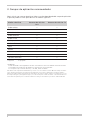 6
6
-
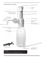 7
7
-
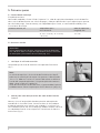 8
8
-
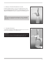 9
9
-
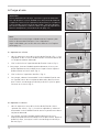 10
10
-
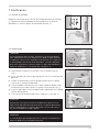 11
11
-
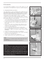 12
12
-
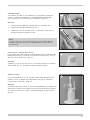 13
13
-
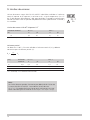 14
14
-
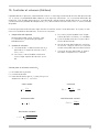 15
15
-
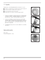 16
16
-
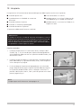 17
17
-
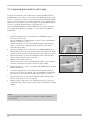 18
18
-
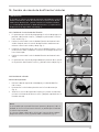 19
19
-
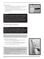 20
20
-
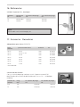 21
21
-
 22
22
-
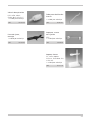 23
23
-
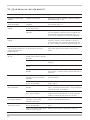 24
24
-
 25
25
-
 26
26
-
 27
27
-
 28
28
-
 29
29
-
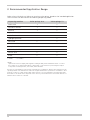 30
30
-
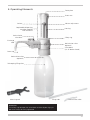 31
31
-
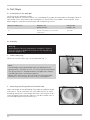 32
32
-
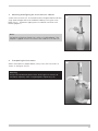 33
33
-
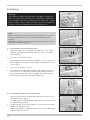 34
34
-
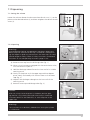 35
35
-
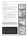 36
36
-
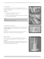 37
37
-
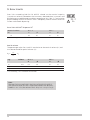 38
38
-
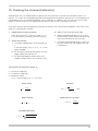 39
39
-
 40
40
-
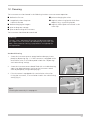 41
41
-
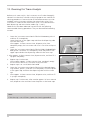 42
42
-
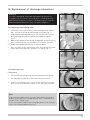 43
43
-
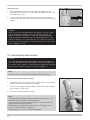 44
44
-
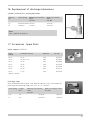 45
45
-
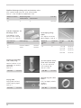 46
46
-
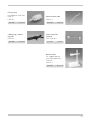 47
47
-
 48
48
-
 49
49
-
 50
50
-
 51
51
-
 52
52


Vitlab TA2 Instrucciones de operación
- Tipo
- Instrucciones de operación
- Este manual también es adecuado para
En otros idiomas
- English: Vitlab TA2 Operating instructions
Otros documentos
-
Brand dispensette Instrucciones de operación
-
-
Mettler Toledo dv1000 Instrucciones de operación
-
dosatron D40 El manual del propietario
-
-
-
Accu-Chek Combo system Guía del usuario
-
GCE COMBILITE 10 YEARS Instrucciones de operación
-
-
Phcbi MCO-170M Instrucciones de operación