
GRTE18
Operating Instruction
DE/EN/FR/PT/IT/ES/ZH/JA/RU
8016953.16B5
OPERATING INSTRUCTION

Described product
GR18
GRTE18
Manufacturer
SICK AG
Erwin-Sick-Str. 1
79183 Waldkirch
Germany
Production location
Legal information
This work is protected by copyright. Any rights derived from the copyright shall be
reserved for SICK AG. Reproduction of this document or parts of this document is only
permissible within the limits of the legal determination of Copyright Law. Any modifica‐
tion, abridgment or translation of this document is prohibited without the express writ‐
ten permission of SICK AG.
The trademarks stated in this document are the property of their respective owner.
© SICK AG. All rights reserved.
Original document
T
his document is an original document of SICK AG.
2006/42/EC
NO
SAFETY
8016953.16B5 | SICK
Subjec
t to change without notice
1

Photoelectric proximity sensor
Operating instructions
2 Safety notes
■
Read the oper
ating instructions before commissioning.
■
Connection, mounting, and setting may only be performed by trained specialists.
■
Not a safety component in accordance with the EU Machinery Directive. Only for use in appli‐
cations in accordance with NFPA 79. UL-listed adapters with connecting cables are available.
Enclosure type 1
■
When commissioning, protect the device from moisture and contamination.
■
These operating instructions contain information required during the life cycle of the sensor.
3 Correct use
The GRTE18 is an opto-electronic photoelectric proximity sensor (referred to as "sensor" in the
following) f
or the optical, non-contact detection of objects, animals, and persons. If the product is
used for any other purpose or modified in any way, any warranty claim against SICK AG shall
become void.
Energetic photoelectric proximity sensor
Image 1: GRTE18-xxxx2
Image 2: GRTE18-xxxx7
Irrtuemer | SICK 1
8016953.16B5

4 Commissioning
1 Check the application conditions: Adjust the sensing range and the remission capability of
the object according to the corresponding diagram [H] (x = sensing range, y = operating
reserve).
During this process, an object can only be detected in front of a background if the remission
capability of the object is significantly higher than that of the background or if the distance
between the object and the background is sufficiently long.
Image 3: H: Sensing range 115 mm
1) Sensing range on black, 6 % r
emission
2) Sensing range on gray, 20 % remission
3) Sensing range on white, 90 % remission
Image 4: H: Sensing range 550 mm
1) Sensing range on black, 6 % r
emission
Commissioning
2 | SICK Irrtuemer
8016953.16B5

2) Sensing range on gray, 20 % remission
3) Sensing range on white, 90 % remission
Image 5: H: Sensing range 800 mm
1) Sensing rang
e on blac
k
, 6 % r
emission
2) Sensing range on gray, 20 % remission
3) Sensing range on white, 90 % remission
2 Mount the sensor using a suitable mounting bracket (see the SICK range of accessories).
Observe the maximum per
missible tightening torque of the sensor of 2.0 Nm for metal/0.9
Nm for plastic [K].
Image: K: GRTE18-x24x7
Commissioning
Irrtuemer | SICK 3
8016953.16B5

Image: K: GRTE18-x24x2
3 The sensors must be connected in a voltage-free state (V
S
= 0 V). The information in t
he gra‐
phics [B] must be observed, depending on the type of connection:
– Male connector connection: pin assignment
– Cable: core color
Image: B: GRTE18-x24xx
Image: B: GRTE18-x11xx
Only apply v
oltage/switch on the power supply (V
S
> 0 V) once all electrical connections have
been completed. The green LED indicator lights up on the sensor.
Explanations of the connection diagram (Graphic B):
Switching outputs Q and /Q (according to Graphic B):
GRTE18-P (PNP: load -> M)
GRTE18-N (NPN: load -> L+)
4 Align the sensor with the object. Select the position so that the red emitted light beam hits
the center of t
he object. You must ensure that the optical opening (front screen) of the sen‐
sor is completely clear [E].
Image 6: E
Commissioning
4 | SICK Irrtuemer
8016953.16B5

5
Sensor with potentiometer:
The sensitivity (sensing range) is adjus
ted with the potentiometer (type: 270°). Clockwise
rotation: sensitivity (sensing range) increased; counterclockwise rotation: sensitivity (sensing
range) reduced. We recommend placing the switching state in the object, e.g., see Graphic F.
Once the sensitivity has been adjusted, the object is removed from the path of the beam.
The switching output changes (see Graphic C).
The sensor is adjusted and ready for operation. Refer to Graphics C and G to check the func‐
tion. If the switching output fails to behave in accordance with Graphic C, check application
conditions. See section Fault diagnosis.
Image 7: C
Commissioning
Irrtuemer | SICK 5
8016953.16B5

Image 8: G
6 Fault diagnosis
Table 7 indicates which measures are to be taken if the sensor stops working.
7 Tab_Fault diagnosis
LED indicator/fault pattern /
LED indicator/fault patt
ern
Cause /
Cause
Measures /
Measures
Green LED does not light up /
Green LED does not light up
N
o voltage or voltage below the
limit values /
No voltage or voltage below the
limit values
Check the power supply, check all
electrical connections (cables and
plug connections) /
Check the power supply, check all
electrical connections (cables and
plug connections)
Green LED does not light up /
Gr
een LED does no
t light up
V
oltage interruptions /
Voltage interruptions
Ensure there is a stable power
supply without interruptions /
Ensure there is a stable power
supply without interruptions
Green LED does not light up /
Green LED does not light up
Sensor is f
aulty /
Sensor is faulty
If the power supply is OK, replace
the sensor /
If the power supply is OK, replace
the sensor
Yellow LED flashes /
Yellow LED f
lashes
Sensor is still ready for operation,
but the operating conditions are
not ideal /
Sensor is still ready for operation,
but the operating conditions are
not ideal
Check the operating conditions:
Fully align the beam of light (light
spot) with the object. / Clean the
optical surfaces / Readjust the
sensitivity (potentiometer) / Check
sensing range and adjust if neces‐
sary, see Graphic E /
Check the operating conditions:
Fully align the beam of light (light
spot) with the object. / Clean the
optical surfaces / Readjust the
sensitivity (potentiometer) /
Check sensing range and adjust if
necessary, see Graphic E
6 | SICK Irrtuemer
8016953.16B5

LED indicator/fault pattern /
LED indicator/fault patter
n
Cause /
Cause
Measures /
Measures
Yellow LED lights up, no object in
t
he pat
h of t
he beam /
Y
ellow LED lights up, no object in
the path of the beam
Remission capability of the back‐
ground is excessive /
Remission capability of the back‐
ground is excessive
Check changes to the back‐
ground. Reduce the sensitivity of
the sensor or use sensors with
background suppression /
Check changes to the back‐
ground. Reduce the sensitivity of
the sensor or use sensors with
background suppression
Object is in the path of the beam,
yellow LED does not light up /
Object is in t
he path of the beam,
yellow LED does not light up
Sensitivity is set too low or dis‐
tance between the sensor and the
object is too long /
Sensitivity is set too low or dis‐
tance between the sensor and the
object is too long
Increase the sensing range, take
note of the distance between the
sensor and the background, see
Graphic E /
Increase the sensing range, take
note of the distance between the
sensor and the background, see
Graphic E
Object is in the path of the beam,
yellow LED does not light up /
Object is in t
he path of the beam,
yellow LED does not light up
Remission capability of the object
is insufficient /
Remission capability of the object
is insufficient
Increase the sensing range, take
note of the distance between the
sensor and the background, see
Graphic E /
Increase the sensing range, take
note of the distance between the
sensor and the background, see
Graphic E
8 Disassembly and disposal
The sensor must be disposed of according to the applicable country-specific regulations. Efforts
should be made during the disposal process t
o recycle the constituent materials (particularly pre‐
cious metals).
9 Maintenance
SICK sensors are maintenance-free.
W
e recommend doing the f
ollowing regularly:
1. Clean the external lens surfaces
2. Check the screw connections and plug-in connections
No modifications may be made to devices.
Subject to change without notice. Specified product properties and technical data are not written
guarantees.
Reflexions-Lichttaster
Betriebsanleitung
12 Sicherheitshinweise
■
Vor der Inbetriebnahme die Be
triebsanleitung lesen.
■
Anschluss, Montage und Einstellung nur durch Fachpersonal.
■
Kein Sicherheitsbauteil gemäß EU-Maschinenrichtlinie. Nur zur Verwendung in Anwendungen
gemäß NFPA 79. Von UL gelistete Adapter mit Anschlusskabeln sind verfügbar. Enclosure
type 1
Disassembly and disposal
Irrtuemer | SICK 7
8016953.16B5

■
Gerät bei Inbetr
iebnahme vor Feuchte und Verunreinigung schützen.
■
Diese Betriebsanleitung enthält Informationen, die während des Lebenszyklus des Sensors
notwendig sind.
13 Bestimmungsgemäße Verwendung
Die GRTE18 ist ein optoelektronischer Reflexions-Lichttaster (im Folgenden Sensor genannt) und
wird zum optischen, berühr
ungslosen Erfassen von Sachen, Tieren und Personen eingesetzt. Bei
jeder anderen Verwendung und bei Veränderungen am Produkt verfällt jeglicher Gewährleis‐
tungsanspruch gegenüber der SICK AG.
Energetischer Reflexionslichttaster
Abb. 9: GRTE18-xxxx2
Abb. 10: GRTE18-xxxx7
14 Inbetriebnahme
1 Einsatzbedingungen prüfen: Schaltabstand und Remissionsvermögen des Objektes mit dem
zug
ehörig
en Diagramm [vgl. H] abgleichen. (x = Schaltabstand, y = Funktionsreserve).
Dabei kann ein Objekt vor einem Hintergrund nur detektiert werden, wenn das Remissions‐
vermögen des Objektes deutlich größer ist als das Remissionsvermögen des Hintergrundes
oder der Abstand zwischen Objekt und Hintergrund ausreichend groß ist.
Sicherheitshinweise
8 | SICK Irrtuemer
8016953.16B5

Abb. 11: H: Sensing range 115 mm
1) Sensing range on black, 6 % r
emission
2) Sensing range on gray, 20 % remission
3) Sensing range on white, 90 % remission
Abb. 12: H: Sensing range 550 mm
1) Sensing range on black, 6 % r
emission
2) Sensing range on gray, 20 % remission
3) Sensing range on white, 90 % remission
Inbetriebnahme
Irrtuemer | SICK 9
8016953.16B5

Abb. 13: H: Sensing range 800 mm
1) Sensing range on black, 6 % r
emission
2) Sensing range on gray, 20 % remission
3) Sensing range on white, 90 % remission
2 Den Sensor an einen geeigneten Befestigungswinkel montieren (siehe SICK-Zubehör-Pro‐
gramm).
Maximal zulässiges Anzugsdrehmoment des Sensor
s von 2,0 Nm für Metall / 0,9 Nm für
Kunststoff beachten [vgl. K].
Abb.: K: GRTE18-x24x7
Abb.: K: GRTE18-x24x2
Inbetriebnahme
10 | SICK Irrtuemer
8016953.16B5

3 Anschluss der Sensoren muss spannungsfrei (V
S
= 0 V) erfolgen. Je nach Anschlussart sind
die Informationen in den Grafiken [vgl. B] zu beachten:
– Steckeranschluss: Pinbelegung
– Leitung: Adernfarbe
Abb.: B: GRTE18-x24xx
Abb.: B: GRTE18-x11xx
Erst nac
h Anschluss aller elektrischen Verbindungen die Spannungsversorgung (V
S
> 0 V)
anlegen bzw. einschalten. Am Sensor leuchtet die grüne Anzeige-LED.
Erläuterungen zum Anschlussschema (Grafik B):
Schaltausgänge Q bzw. /Q (gemäß Grafik B):
GRTE18-P (PNP: Last -> M)
GRTE18-N (NPN: Last -> L+)
4 Sensor auf Objekt ausrichten. Positionierung so wählen, dass der rote Sendelichtstrahl in
der Mitte des Objekts auftr
ifft. Es ist darauf zu achten, dass die optische Öffnung (Front‐
scheibe) des Sensors vollständig frei ist [vgl. E].
Abb. 14: E
Inbetriebnahme
Irrtuemer | SICK 11
8016953.16B5

5
Sensor mit Potentiometer:
Mit dem Pot
entiometer (Art: 270°) wird die Empfindlichkeit (Schaltabstand) eingestellt. Dre‐
hung nach rechts: Erhöhung der Empfindlichkeit (Schaltabstand), Drehung nach links: Ver‐
ringerung der Empfindlichkeit (Schaltabstand). Wir empfehlen, den Schaltabstand in das
Objekt zu legen, z.B. siehe Grafik F. Nachdem die Empfindlichkeit eingestellt worden ist, das
Objekt aus dem Strahlengang entfernen. Der Schaltausgang ändert sich (siehe Grafik C).
Sensor ist eingestellt und betriebsbereit. Zur Überprüfung der Funktion Grafik C und G
heranziehen. Verhält sich der Schaltausgang nicht gemäß Grafik C, Einsatzbedingungen prü‐
fen. Siehe Abschnitt Fehlerdiagnose.
Abb. 15: C
Inbetriebnahme
12 | SICK Irrtuemer
8016953.16B5

Abb. 16: G
16 Fehlerdiagnose
Tabelle 17 zeigt, welche Maßnahmen durchzuführen sind, wenn die Funktion des Sensors nicht
mehr g
egeben is
t.
17 Tab_Fehlerdiagnose
Anzeige-LED / Fehlerbild /
LED indicator/fault pattern
Ursache /
Cause
Maßnahme /
Measures
grüne LED leuchtet nicht /
Green LED does not light up
k
eine Spannung oder Spannung
unterhalb der Grenzwerte /
No voltage or voltage below the
limit values
Spannungsversorgung prüfen,
den gesamten elektrischen
Anschluss prüfen (Leitungen und
Steckerverbindungen) /
Check the power supply, check all
electrical connections (cables and
plug connections)
grüne LED leuchtet nicht /
Green LED does not light up
Spannungsunt
erbrechungen /
Voltage interruptions
Sicherstellen einer stabilen Span‐
nungsversorgung ohne Unterbre‐
chungen /
Ensure there is a stable power
supply without interruptions
grüne LED leuchtet nicht /
Green LED does not light up
Sensor is
t defekt /
Sensor is faulty
Wenn Spannungsversorgung in
Ordnung ist, dann Sensor austau‐
schen /
If the power supply is OK, replace
the sensor
gelbe LED blinkt /
Yellow LED f
lashes
Sensor ist noch betriebsbereit,
aber die Betriebsbedingungen
sind nicht optimal /
Sensor is still ready for operation,
but the operating conditions are
not ideal
Betriebsbedingungen prüfen:
Lichtstrahl (Lichtfleck) vollständig
auf das Objekt ausrichten / Reini‐
gung der optischen Flächen /
Empfindlichkeit (Potentiometer)
neu einstellen / Schaltabstand
überprüfen und ggfs. anpassen,
siehe Grafik E /
Check the operating conditions:
Fully align the beam of light (light
spot) with the object. / Clean the
optical surfaces / Readjust the
sensitivity (potentiometer) /
Check sensing range and adjust if
necessary, see Graphic E
Irrtuemer | SICK 13
8016953.16B5

Anzeige-LED / Fehlerbild /
LED indicator/fault patter
n
Ursache /
Cause
Maßnahme /
Measures
gelbe LED leuchtet, kein Objekt im
Strahleng
ang /
Y
ello
w LED lights up, no object in
t
he path of the beam
Remissionsvermögen des Hinter‐
grundes zu hoch /
Remission capability of the back‐
ground is excessive
Veränderungen des Hintergrundes
prüfen. Empfindlichkeit des Sen‐
sors reduzieren oder Taster mit
Hintergrundausblendung verwen‐
den /
Check changes to the back‐
ground. Reduce the sensitivity of
the sensor or use sensors with
background suppression
Objekt ist im Strahlengang, gelbe
LED leuchtet nic
ht /
Object is in the path of the beam,
yellow LED does not light up
Empfindlichkeit ist zu gering ein‐
gestellt oder Abstand zwischen
Sensor und Objekt ist zu groß /
Sensitivity is set too low or dis‐
tance between the sensor and the
object is too long
Schaltabstand vergrößern,
Abstand zwischen Sensor und
Hintergrund beachten, siehe Gra‐
fik E /
Increase the sensing range, take
note of the distance between the
sensor and the background, see
Graphic E
Objekt ist im Strahlengang, gelbe
LED leuchtet nic
ht /
Object is in the path of the beam,
yellow LED does not light up
Remissionsvermögen des Objek‐
tes ist zu gering /
Remission capability of the object
is insufficient
Schaltabstand vergrößern,
Abstand zwischen Sensor und
Hintergrund beachten, siehe Gra‐
fik E /
Increase the sensing range, take
note of the distance between the
sensor and the background, see
Graphic E
18 Demontage und Entsorgung
Die Entsorgung des Sensors hat gemäß den länderspezifisch anwendbaren Vorschriften zu erfol‐
gen. Für die enthaltenen W
ertstoffe (insbesondere Edelmetalle) ist im Rahmen der Entsorgung
eine Verwertung anzustreben.
19 Wartung
SICK-Sensoren sind wartungsfrei.
W
ir empfehlen, in r
egelmäßigen Abständen
1. die optischen Grenzflächen zu reinigen
2. Verschraubungen und Steckverbindungen zu überprüfen
Veränderungen an Geräten dürfen nicht vorgenommen werden.
Irrtümer und Änderungen vorbehalten. Angegebene Produkteigenschaften und technische Daten
stellen keine Garantieerklärung dar.
Détecteur à réflexion directe
Notice d'instruction
22
Consignes de sécurité
■
Lire la notice d'instr
uction avant la mise en service.
■
Confier le raccordement, le montage et le réglage uniquement à un personnel spécialisé.
Demontage und Entsorgung
14 | SICK Irrtuemer
8016953.16B5

■
Il ne s'agit pas d'un composant de sécurit
é au sens de la directive machines CE. Utilisation
uniquement pour des applications selon la NFPA 79 Des adaptateurs listés UL avec câbles
de connexion sont disponibles. Enclosure type 1
■
Protéger l'appareil contre l'humidité et les impuretés lors de la mise en service.
■
Cette notice d'instruction contient des informations nécessaires pendant toute la durée de
vie du capteur.
23 Utilisation conforme
GRTE18 est un détecteur à réflexion directe optoélectronique (appelé capteur dans ce document)
qui perme
t la détection optique sans contact d'objets, d'animaux et de personnes. Toute autre
utilisation ou modification du produit annule la garantie de SICK AG.
Détecteur énergétique à réflexion directe
Image 17: GRTE18-xxxx2
Image 18: GRTE18-xxxx2
24 Mise en service
1 Vérifier les conditions d'utilisation : comparer la portée et les caractéristiques de réflectivité
de l'obje
t à l'aide du diagr
amme [E] correspondant. (x = portée, y = réserve de fonctionne‐
ment).
Consignes de sécurité
Irrtuemer | SICK 15
8016953.16B5

Ce faisant, il n'est possible de détecter un objet devant un arrière-plan que si les caractéris‐
tiques de réflectivité de l'objet sont largement supérieures à celles de l'arrière-plan en ques‐
tion ou si la distance entre l'objet et l'arrière-plan est suffisante.
Image 19: H: Sensing range 115 mm
1) Sensing range on black, 6 % r
emission
2) Sensing range on gray, 20 % remission
3) Sensing range on white, 90 % remission
Image 20: H: Sensing range 550 mm
1) Sensing range on black, 6 % r
emission
2) Sensing range on gray, 20 % remission
3) Sensing range on white, 90 % remission
Mise en service
16 | SICK Irrtuemer
8016953.16B5

Image 21: H: Sensing range 800 mm
1) Sensing range on black, 6 % r
emission
2) Sensing range on gray, 20 % remission
3) Sensing range on white, 90 % remission
2 Monter le capteur sur une équerre de fixation adaptée (voir la gamme d'accessoires SICK).
Respecter le couple de serr
age maximal admissible du capteur de 2,0 Nm pour métal / 0,9
Nm pour plastique [voir K].
Image: K: GRTE18-x24x7
Image: K: GRTE18-x24x2
3 Le raccordement des capteurs doit s'effectuer hors tension (V
S
= 0 V). Selon le mode de rac‐
cordement, respecter les informations contenues dans les schémas [B] :
Mise en service
Irrtuemer | SICK 17
8016953.16B5

– Raccordement du connecteur : affectation des broches
– Câble : couleur des fils
Image: B: GRTE18-x24xx
Image: B: GRTE18-x11xx
Après av
oir terminé tous les raccordements électriques, enclencher l'alimentation électrique
(V
S
> 0 V). La DEL verte s'allume sur le capteur.
Explications relatives au schéma de raccordement (schéma B) :
Sorties de commutation Q ou /Q (selon le schéma B) :
GRTE18-P (PNP : charge -> M)
GRTE18-N (NPN : charge -> L+)
4 Aligner le capteur sur l'objet. Sélectionner la position de sorte que le faisceau lumineux émis
rouge t
ouche l'objet en plein milieu. S'assurer que l'ouverture optique (vitre frontale) du cap‐
teur est parfaitement dégagée [voir E].
Image 22: E
5
Mise en service
18 | SICK Irrtuemer
8016953.16B5

Capteur avec potentiomètre :
Le potentiomètre (réf. : 270°) permet de régler la sensibilité (portée). Rotation vers la
droite : augmentation de la sensibilité (portée), rotation vers la gauche : réduction de la sen‐
sibilité (portée). Nous recommandons de régler la portée sur l'objet, par ex. voir schéma F.
Après le réglage de la sensibilité, retirer l'objet de la trajectoire du faisceau. La sortie de
commutation bascule (voir schéma C).
Le capteur est réglé et prêt à être utilisé. Pour contrôler le fonctionnement, utiliser les sché‐
mas C et G. Si la sortie de commutation ne se comporte pas comme indiqué sur le schéma
C, vérifier les conditions d'utilisation. Voir la section consacrée au diagnostic.
Image 23: C
Image 24: G
26 Diagnostic
Le tableau 27 présente les mesures à appliquer si le capteur ne fonctionne plus.
Irrtuemer | SICK 19
8016953.16B5

27 Tab_Diagnostic
LED d'état / image du défaut /
LED indicator/fault patt
ern
Cause /
Cause
/
Measures
La LED verte ne s'allume pas /
Gr
een LED does no
t light up
P
as de tension ou tension infér‐
ieure aux valeurs limites /
No voltage or voltage below the
limit values
Contrôler l'alimentation électri‐
que, contrôler tous les branche‐
ments électriques (câbles et con‐
nexions) /
Check the power supply, check all
electrical connections (cables and
plug connections)
La LED verte ne s'allume pas /
Green LED does not light up
Coupur
es d'alimentation électri‐
que /
Voltage interruptions
S'assurer que l'alimentation élect‐
rique est stable et ininterrompue /
Ensure there is a stable power
supply without interruptions
La LED verte ne s'allume pas /
Green LED does not light up
Le capt
eur est défectueux /
Sensor is faulty
Si l'alimentation électrique est en
bon état, remplacer le capteur /
If the power supply is OK, replace
the sensor
La LED jaune clignote /
Yellow LED f
lashes
Le capteur est encore opération‐
nel, mais les conditions d'utilisa‐
tion ne sont pas idéales /
Sensor is still ready for operation,
but the operating conditions are
not ideal
Vérifier les conditions d'utilisa‐
tion : Diriger le faisceau lumineux
(spot lumineux) entièrement sur
l'objet / Nettoyage des surfaces
optiques / Régler à nouveau la
sensibilité (potentiomètre) / Con‐
trôler la portée et éventuellement
l'adapter, voir le schéma E /
Check the operating conditions:
Fully align the beam of light (light
spot) with the object. / Clean the
optical surfaces / Readjust the
sensitivity (potentiometer) /
Check sensing range and adjust if
necessary, see Graphic E
La LED jaune s'allume, pas d'objet
dans la traject
oire du faisceau /
Yellow LED lights up, no object in
the path of the beam
Le pouvoir réfléchissant de l'arri‐
ère-plan est trop élevé /
Remission capability of the back‐
ground is excessive
Contrôler les variations de l'arri‐
ère-plan Diminuer la sensibilité du
capteur ou utiliser un capteur à
élimination d'arrière-plan /
Check changes to the back‐
ground. Reduce the sensitivity of
the sensor or use sensors with
background suppression
L'objet est dans la trajectoire du
faisceau, la LED jaune ne s'allume
pas /
Object is in the pat
h of the beam,
yellow LED does not light up
La sensibilité est trop faible ou la
distance entre le capteur et l'objet
est trop grande /
Sensitivity is set too low or dis‐
tance between the sensor and the
object is too long
Augmenter la portée, tenir compte
de la distance entre le capteur et
l'arrière-plan, voir le schéma E /
Increase the sensing range, take
note of the distance between the
sensor and the background, see
Graphic E
L'objet est dans la trajectoire du
faisceau, la LED jaune ne s'allume
pas /
Object is in the pat
h of the beam,
yellow LED does not light up
Le pouvoir réfléchissant de l'arri‐
ère-plan est trop faible /
Remission capability of the object
is insufficient
Augmenter la portée, tenir compte
de la distance entre le capteur et
l'arrière-plan, voir le schéma E /
Increase the sensing range, take
note of the distance between the
sensor and the background, see
Graphic E
Tab_Diagnostic
20 | SICK Irrtuemer
8016953.16B5

28 Démontage et mise au rebut
La mise au rebut du capteur doit respecter la réglementation nationale en vigueur. Dans le cadre
de la mise au rebut, veiller à recycler les matériaux (notamment les métaux précieux).
29 Maintenance
Les capteurs SICK ne nécessitent aucune maintenance.
Nous vous recommandons de pr
océder régulièrement
1. au nettoyage des surfaces optiques
2. au contrôle des vissages et des connexions enfichables
Ne procéder à aucune modification sur les appareils.
Sujet à modification sans préavis. Les caractéristiques du produit et techniques fournies ne sont
pas une déclaration de garantie.
Interruptor fotoelétrico de reflexão
Manual de instruções
32 Notas de segurança
■
Ler as instruções de operação ant
es da colocação em funcionamento.
■
A conexão, a montagem e o ajuste devem ser executados somente por pessoal técnico quali‐
ficado.
■
Os componentes de segurança não se encontram em conformidade com a Diretiva Europeia
de Máquinas. Somente na utilização em aplicações de acordo com NFPA 79. Estão disponív‐
eis adaptadores listados pela UL com cabos de conexão. Enclosure type 1
■
Durante o funcionamento, manter o aparelho protegido contra impurezas e umidade.
■
Este manual de instruções contém informações necessárias para toda a vida útil do sensor.
33 Especificações de uso
O GRTE18 é um sensor fotoelétrico de proximidade utilizado para a detecção óptica, sem con‐
t
ato, de objet
os, animais e pessoas. Qualquer utilização diferente ou alterações do produto pro‐
vocam a perda da garantia da SICK AG.
Interruptor fotoelétrico de reflexão energético
Démontage et mise au rebut
Irrtuemer | SICK 21
8016953.16B5

Image 25: GRTE18-xxxx2
Image 26: GRTE18-xxxx7
34 Colocação em funcionamento
1 Verificar as condições de uso: equiparar a distância de comutação e a refletividade do
obje
to com o r
espectivo diagrama [cp. H]. (x = distância de comutação, y = reserva de fun‐
ção).
Um objeto só pode ser detectado à frente de um fundo, se a refletividade do objeto for signi‐
ficativamente maior do que a refletividade do fundo ou se a distância entre o objeto e o
fundo for suficientemente grande.
Especificações de uso
22 | SICK Irrtuemer
8016953.16B5

Image 27: H: Sensing range 115 mm
1) Sensing range on black, 6 % r
emission
2) Sensing range on gray, 20 % remission
3) Sensing range on white, 90 % remission
Image 28: H: Sensing range 550 mm
1) Sensing range on black, 6 % r
emission
2) Sensing range on gray, 20 % remission
3) Sensing range on white, 90 % remission
Colocação em funcionamento
Irrtuemer | SICK 23
8016953.16B5

Image 29: H: Sensing range 800 mm
1) Sensing range on black, 6 % r
emission
2) Sensing range on gray, 20 % remission
3) Sensing range on white, 90 % remission
2 Montar o sensor numa cantoneira de fixação adequada (ver linha de acessórios da SICK).
Observar o tor
que de aperto máximo permitido do sensor de 2,0 Nm para metal / 0,9 Nm
para plástico [cp. K].
Image: K: GRTE18-x24x7
Image: K: GRTE18-x24x2
3 A conexão dos sensores deve ser realizada em estado desenergizado (V
S
= 0 V). Conforme o
tipo de conexão, devem ser observadas as informações contidas nos gráficos [cp. B]:
Colocação em funcionamento
24 | SICK Irrtuemer
8016953.16B5

– Conector: Pin-out
– Cabo: Cor dos fios
Image: B: GRTE18-x24xx
Image: B: GRTE18-x11xx
Instalar ou lig
ar a alimentação de tensão (V
S
> 0 V) somente após a conclusão de todas as
conexões elétricas. O indicador LED verde está aceso no sensor.
Explicações relativas ao esquema de conexões (Gráfico B):
Saídas de comutação Q ou /Q (conforme o gráfico B):
GRTE18-P (PNP: carga -> M)
GRTE18-N (NPN: carga -> L+)
4 Alinhar o sensor ao objeto. Posicionar, de forma que o feixe da luz de emissão vermelha
incida sobre o centro do obje
to. Certificar-se de que a abertura óptica (vidro frontal) do sen‐
sor esteja completamente livre [cp. E].
Image 30: E
5
Colocação em funcionamento
Irrtuemer | SICK 25
8016953.16B5

Sensor com potenciômetro:
O potenciômetro (tipo: 270°) permite o ajuste da sensibilidade (distância de comutação).
Giro para direita: aumento da sensibilidade (distância de comutação); giro para esquerda:
redução da sensibilidade (distância de comutação). Recomendamos posicionar a distância
de comutação no objeto, por ex., como no gráfico F. Após o ajuste da sensibilidade, remover
o objeto do caminho óptico. A saída de comutação se modifica (ver gráfico C).
O sensor está ajustado e operacional. Utilizar os gráficos C e G para verificar o funciona‐
mento. Se a saída de comutação não se comportar de acordo com o gráfico C, verificar as
condições de uso. Ver seção Diagnóstico de erros.
Image 31: C
Image 32: G
36 Diagnóstico de erros
A tabela 37 mostra as medidas a serem executadas, quando o sensor não estiver funcionando.
26 | SICK Irrtuemer
8016953.16B5

37 Tab_Diagnóstico de erros
Indicador LED / padrão de erro /
LED indicator/fault patt
ern
Causa /
Cause
Medida /
Measures
LED verde apagado /
Gr
een LED does no
t light up
Sem t
ensão ou tensão abaixo dos
valores-limite /
No voltage or voltage below the
limit values
Verificar a alimentação de tensão,
verificar toda a conexão elétrica
(cabos e conectores) /
Check the power supply, check all
electrical connections (cables and
plug connections)
LED verde apagado /
Green LED does not light up
Int
errupções de tensão /
Voltage interruptions
Assegurar uma alimentação de
tensão estável sem interrupções /
Ensure there is a stable power
supply without interruptions
LED verde apagado /
Green LED does not light up
Sensor es
tá com defeito /
Sensor is faulty
Se a alimentação de tensão esti‐
ver em ordem, substituir o sen‐
sor /
If the power supply is OK, replace
the sensor
LED amarelo intermitente /
Y
ello
w LED f
lashes
Sensor ainda está operacional,
mas as condições de operação
não são ideais /
Sensor is still ready for operation,
but the operating conditions are
not ideal
Verificar as condições de opera‐
ção: Alinhar o feixe de luz (ponto
de luz) completamente ao
objeto / Limpeza das superfícies
ópticas / reajustar a sensibilidade
(potenciômetro) / Verificar e, se
necessário, adaptar a distância
de comutação, ver gráfico E /
Check the operating conditions:
Fully align the beam of light (light
spot) with the object. / Clean the
optical surfaces / Readjust the
sensitivity (potentiometer) /
Check sensing range and adjust if
necessary, see Graphic E
LED amarelo aceso, nenhum
objeto no caminho óp
tico /
Yellow LED lights up, no object in
the path of the beam
Refletividade do fundo alta
demais /
Remission capability of the back‐
ground is excessive
Verificar as modificações do
fundo. Reduzir a sensibilidade do
sensor ou usar o botão com a
supressão de fundo /
Check changes to the back‐
ground. Reduce the sensitivity of
the sensor or use sensors with
background suppression
Objeto está no caminho óptico,
LED amarelo apagado /
Object is in t
he path of the beam,
yellow LED does not light up
Sensibilidade foi ajustada para
um valor baixo demais ou a dis‐
tância entre sensor e objeto é
grande demais /
Sensitivity is set too low or dis‐
tance between the sensor and the
object is too long
Aumentar a distância de comuta‐
ção, observar a distância entre
sensor e fundo, ver gráfico E /
Increase the sensing range, take
note of the distance between the
sensor and the background, see
Graphic E
Objeto está no caminho óptico,
LED amarelo apagado /
Object is in t
he path of the beam,
yellow LED does not light up
Refletividade do fundo baixa
demais /
Remission capability of the object
is insufficient
Aumentar a distância de comuta‐
ção, observar a distância entre
sensor e fundo, ver gráfico E /
Increase the sensing range, take
note of the distance between the
sensor and the background, see
Graphic E
Tab_Diagnóstico de erros
Irrtuemer | SICK 27
8016953.16B5

38 Desmontagem e descarte
O descarte do sensor deve ser efetuado de acordo com as normas aplicáveis específicas de cada
país. No âmbito do descarte, deve-se procurar o aproveitamento dos materiais recicláveis conti‐
dos (principalmente dos metais nobres).
39 Manutenção
Os sensores SICK não requerem manutenção.
Recomendamos que se efe
tue em intervalos regulares
1. uma limpeza das superfícies ópticas
2. uma verificação das conexões roscadas e dos conectores
Não são permitidas modificações no aparelho.
Sujeito a alterações sem aviso prévio. As propriedades do produto e os dados técnicos especifi‐
cados não constituem nenhum certificado de garantia.
Sensore di luce a riflessione
Istruzioni per l'uso
42 Avvertenze sulla sicurezza
■
Prima della messa in funzionamento legger
e le istruzioni per l'uso.
■
Allacciamento, montaggio e regolazione solo a cura di personale tecnico specializzato.
■
Nessun componente di sicurezza ai sensi della direttiva macchine UE. Solo per l'utilizzo in
applicazioni ai sensi di NFPA 79. Sono a disposizione adattatori con cavo di connessione dell‐
'elenco UL. Enclosure type 1
■
Alla messa in funzionamento proteggere l'apparecchio dall'umidità e dalla sporcizia.
■
Queste istruzioni per l'uso contengono le informazioni che sono necessarie durante il ciclo di
vita del sensore fotoelettrico. deTec4 core
43 Uso conforme alle prescrizioni
La GRTE18 è una fotocellula a riflessione optoelettronica (di seguito nominato sensore) utilizzata
per il r
ilevament
o ottico senza contatto di oggetti, animali e persone. Se viene utilizzata diversa‐
mente e in caso di modifiche sul prodotto, decade qualsiasi diritto alla garanzia nei confronti di
SICK.
Relè fotoelettrico a riflessione a energia
Desmontagem e descarte
28 | SICK Irrtuemer
8016953.16B5

Image 33: GRTE18-xxxx2
Image 34: GRTE18-xxxx7
44 Messa in funzionamento
1 Verificare le condizioni d'impiego: predisporre la distanza di commutazione e il fattore di rif‐
lessione dell'ogg
ett
o in base al relativo diagramma [cfr. H] . (x = distanza di commutazione, y
= riserva di funzionamento).
Inoltre la rilevazione di un oggetto da uno sfondo è possibile soltanto qualora il fattore di
riflessione dell'oggetto superi nettamente quello dello sfondo o la distanza tra oggetto e
sfondo sia sufficientemente grande.
Uso conforme alle prescrizioni
Irrtuemer | SICK 29
8016953.16B5

Image 35: H: Sensing range 115 mm
1) Sensing range on black, 6 % r
emission
2) Sensing range on gray, 20 % remission
3) Sensing range on white, 90 % remission
Image 36: H: Sensing range 550 mm
1) Sensing range on black, 6 % r
emission
2) Sensing range on gray, 20 % remission
3) Sensing range on white, 90 % remission
Messa in funzionamento
30 | SICK Irrtuemer
8016953.16B5

Image 37: H: Sensing range 800 mm
1) Sensing range on black, 6 % r
emission
2) Sensing range on gray, 20 % remission
3) Sensing range on white, 90 % remission
2 Montare il sensore su un punto di fissaggio adatto (vedi il programma per accessori SICK).
Rispettare il moment
o torcente massimo consentito del sensore di 2,0 Nm per il metallo /
0,9 Nm per la plastica [cfr. K].
Image: K: GRTE18-x24x7
Image: K: GRTE18-x24x2
3 Il collegamento dei sensori deve avvenire in assenza di tensione (V
S
= 0 V). In base al tipo di
collegamento si devono rispettare le informazioni nei grafici [cfr. B]:
Messa in funzionamento
Irrtuemer | SICK 31
8016953.16B5

– Collegamento a spina: assegnazione pin
– Conduttore: colore filo
Image: B: GRTE18-x24xx
Image: B: GRTE18-x11xx
Solamente in seguito alla conclusione di tutti i colleg
amenti elettrici, ripristinare o accendere
l'alimentazione di tensione (V
S
> 0 V). Sul sensore si accende l'indicatore LED verde.
Spiegazioni dello schema di collegamento (grafico B):
Uscite di commutazione Q ovvero /Q (conformemente al grafico B):
GRTE18-P (PNP: carico -> M)
GRTE18-N (NPN: carico -> L+)
4 Orientare reciprocamente il sensore sul rispettivo oggetto. Scegliere la posizione in modo
tale che il r
aggio di luce rosso emesso colpisca il centro dell'oggetto. Fare attenzione che
l'apertura ottica del sensore (finestrella frontale) sia completamente libera [cfr. E].
Image 38: E
5
Messa in funzionamento
32 | SICK Irrtuemer
8016953.16B5

Sensore con potenziometro:
Con il potenziometro (tipo: 270°) viene impostata la sensibilità (distanza di commutazione).
Rotazione verso destra: innalzamento della sensibilità (distanza di commutazione), rota‐
zione verso sinistra: riduzione della sensibilità (distanza di commutazione). Si consiglia di
fissare la distanza di commutazione nell'oggetto, ad es. vedi grafico F. Dopo l'impostazione
della sensibilità, allontanare l'oggetto dalla traiettoria del raggio. L'uscita di commutazione
cambia (vedi grafico C).
Il sensore è impostato e pronto per il funzionamento. Per verificare il funzionamento, osser‐
vare i grafici C e G. Se l'uscita di commutazione non si comporta conformemente al grafico
C, verificare le condizioni d'impiego. Vedi paragrafo diagnostica delle anomalie.
Image 39: C
Image 40: G
46 Diagnostica delle anomalie
Tabella 47 mostra quali provvedimenti si devono adottare quando il sensore non funziona più.
Irrtuemer | SICK 33
8016953.16B5

47 Tabulatore_diagnostica delle anomalie
Indicatore LED / figura di errore /
LED indicator/fault patt
ern
Causa /
Cause
Provvedimento /
Measures
Il LED verde non si accende /
Gr
een LED does no
t light up
nessuna t
ensione o tensione al di
sotto del valore soglia /
No voltage or voltage below the
limit values
Verificare la tensione di alimenta‐
zione e/o il collegamento elett‐
rico /
Check the power supply, check all
electrical connections (cables and
plug connections)
Il LED verde non si accende /
Green LED does not light up
Int
erruzioni di tensione /
Voltage interruptions
Assicurarsi che ci sia un'alimenta‐
zione di tensione stabile /
Ensure there is a stable power
supply without interruptions
Il LED verde non si accende /
Green LED does not light up
Il sensor
e è guasto /
Sensor is faulty
Se l'alimentazione di tensione è
regolare, allora chiedere una sos‐
tituzione del sensore /
If the power supply is OK, replace
the sensor
il LED giallo lampeggia /
Y
ello
w LED f
lashes
Il sensore è ancora pronto per il
funzionamento, ma le condizioni
di esercizio non sono ottimali /
Sensor is still ready for operation,
but the operating conditions are
not ideal
Controllare le condizioni di eserci‐
zio: Dirigere il raggio di luce (il
punto luminoso) completamente
sull'oggetto / Pulizia delle super‐
fici ottiche / Sensibilità (potenzio‐
metro) / Controllare la distanza di
commutazione e, se necessario,
adattarla, vedi grafico E /
Check the operating conditions:
Fully align the beam of light (light
spot) with the object. / Clean the
optical surfaces / Readjust the
sensitivity (potentiometer) /
Check sensing range and adjust if
necessary, see Graphic E
il LED giallo si accende, nessun
oggett
o nella traiettoria del raggio /
Yellow LED lights up, no object in
the path of the beam
Fattore di riflessione dello sfondo
troppo alto /
Remission capability of the back‐
ground is excessive
Controllare le variazioni dello
sfondo. Ridurre la sensibilità del
sensore oppure utilizzare il tasto
con soppressione dello sfondo /
Check changes to the back‐
ground. Reduce the sensitivity of
the sensor or use sensors with
background suppression
L'oggetto è nella traiettoria del rag‐
gio, il LED giallo non si accende /
Object is in the path of t
he beam,
yellow LED does not light up
La sensibilità ha un'impostazione
troppo bassa o la distanza tra
sensore e oggetto è troppo
grande /
Sensitivity is set too low or dis‐
tance between the sensor and the
object is too long
Aumentare la distanza di commu‐
tazione, rispettare la distanza tra
sensore e sfondo, vedi grafico E /
Increase the sensing range, take
note of the distance between the
sensor and the background, see
Graphic E
L'oggetto è nella traiettoria del rag‐
gio, il LED giallo non si accende /
Object is in the path of t
he beam,
yellow LED does not light up
Il fattore di riflessione dell'oggetto
è troppo basso /
Remission capability of the object
is insufficient
Aumentare la distanza di commu‐
tazione, rispettare la distanza tra
sensore e sfondo, vedi grafico E /
Increase the sensing range, take
note of the distance between the
sensor and the background, see
Graphic E
Tabulatore_diagnostica delle anomalie
34 | SICK Irrtuemer
8016953.16B5

48 Smontaggio e smaltimento
Lo smaltimento del sensore deve avvenire conformemente alle direttive previste specificata‐
mente dal paese. Per i materiali riciclabili in esso contenuti (in particolare metalli nobili) si aus‐
pica un riciclaggio nell'ambito dello smaltimento.
49 Manutenzione
I sensori SICK sono esenti da manutenzione.
A intervalli r
egolari si consiglia di
1. pulire le superfici limite ottiche
2. Verificare i collegamenti a vite e gli innesti a spina
Non è consentito effettuare modifiche agli apparecchi.
Contenuti soggetti a modifiche senza preavviso. Le proprietà del prodotto e le schede tecniche
indicate non costituiscono una dichiarazione di garanzia.
Sensor fotoeléctrico de reflexión
Instrucciones de uso
52 Instrucciones de seguridad
■
Lea las instrucciones de uso antes de ef
ectuar la puesta en servicio.
■
La conexión, el montaje y el ajuste deben ser efectuados exclusivamente por técnicos especi‐
alistas.
■
No se trata de un componente de seguridad según la Directiva de máquinas de la UE. Solo
para utilizar en aplicaciones según NFPA 79. Se encuentran disponibles adaptadores con
cables de conexión listados por UL. Enclosure type 1
■
Proteja el equipo contra la humedad y la suciedad durante la puesta en servicio.
■
Las presentes instrucciones de uso contienen información que puede serle necesaria
durante todo el ciclo de vida del sensor.
53 Uso conforme a lo previsto
El GRTE18 es un sensor optoelectrónico de reflexión (en lo sucesivo llamado sensor) empleado
par
a la detección óptica y sin cont
acto de objetos, animales y personas. Cualquier uso diferente
al previsto o modificación en el producto invalidará la garantía por parte de SICK AG.
Sensor fotoeléctrico de reflexión energético
Smontaggio e smaltimento
Irrtuemer | SICK 35
8016953.16B5

Image 41: GRTE18-xxxx2
Image 42: GRTE18-xxxx2
54 Puesta en servicio
1 Comprobar las condiciones de aplicación: comparar la distancia de conmutación y la capaci‐
dad de r
emisión del objet
o con el diagrama correspondiente [véase fig. H]. (x = distancia de
conmutación, y = reserva de funcionamiento.)
En este caso, los objetos situados delante de un fondo solo se podrán detectar si la capaci‐
dad de remisión del objeto es considerablemente superior a la del fondo o la distancia entre
el objeto y el fondo es suficientemente grande.
Uso conforme a lo previsto
36 | SICK Irrtuemer
8016953.16B5

Image 43: H: Sensing range 115 mm
1) Sensing range on black, 6 % r
emission
2) Sensing range on gray, 20 % remission
3) Sensing range on white, 90 % remission
Image 44: H: Sensing range 550 mm
1) Sensing range on black, 6 % r
emission
2) Sensing range on gray, 20 % remission
3) Sensing range on white, 90 % remission
Puesta en servicio
Irrtuemer | SICK 37
8016953.16B5

Image 45: H: Sensing range 800 mm
1) Sensing range on black, 6 % r
emission
2) Sensing range on gray, 20 % remission
3) Sensing range on white, 90 % remission
2 Montar el sensor en una escuadra de fijación adecuada (véase el programa de accesorios
SICK).
Respet
ar el par de apriete máximo admisible del sensor de 2,0 Nm para metal y 0,9 Nm
para plástico [véase K].
Image: K: GRTE18-x24x7
Image: K: GRTE18-x24x2
Puesta en servicio
38 | SICK Irrtuemer
8016953.16B5

3 Los sensores deben conectarse sin tensión (V
S
= 0 V). Debe tenerse en cuenta la informa‐
ción de las figuras [B] en función de cada tipo de conexión:
– Conexión de enchufes: asignación de pines
– Cable: color del hilo
Image: B: GRTE18-x24xx
Image: B: GRTE18-x11xx
No conectar o aplicar la fuent
e de alimentación (V
S
> 0 V) hasta que no se hayan realizado
todas las conexiones eléctricas. En el sensor se ilumina el LED indicador verde.
Explicaciones relativas al esquema de conexión (figura B)
Salidas conmutadas Q o /Q (según figura B):
GRTE18-P (PNP: carga -> M)
GRTE18-N (NPN: carga -> L+)
4 Oriente el sensor hacia el objeto. Seleccione una posición que permita que el haz de luz roja
del transmisor incida en el centro del obje
to. Hay que procurar que la apertura óptica (pan‐
talla frontal) del sensor esté completamente libre [véase figura E].
Image 46: E
Puesta en servicio
Irrtuemer | SICK 39
8016953.16B5

5
Sensor con potenciómetro:
Con el potencióme
tro (tipo: 270°) se ajusta la sensibilidad (distancia de conmutación). Giro
hacia la derecha: aumenta la sensibilidad (distancia de conmutación); giro hacia la
izquierda: se reduce la sensibilidad (distancia de conmutación). Recomendamos poner la
distancia de conmutación en el objeto, p. ej., véase figura F. Una vez ajustada la sensibili‐
dad, retirar el objeto de la trayectoria del haz. La salida conmutada cambia (véase figura C).
El sensor está ajustado y listo para su uso. Para verificar el funcionamiento, véanse las figu‐
ras C y G. Si la salida conmutada no se comporta según la figura C, comprobar las condicio‐
nes de aplicación. Véase la sección "Diagnóstico de fallos".
Image 47: C
Puesta en servicio
40 | SICK Irrtuemer
8016953.16B5

Image 48: G
56 Diagnóstico de fallos
La tabla 57 muestra las acciones que hay que tomar cuando ya no está indicado el funciona‐
mient
o del sensor.
57
Tabla_Diagnóstico de fallos
LED indicador / imagen de error /
LED indicator/fault pattern
Causa /
Cause
Acción /
Measures
El LED verde no se ilumina /
Green LED does not light up
Sin t
ensión o tensión por debajo
de los valores límite /
No voltage or voltage below the
limit values
Comprobar la fuente de alimenta‐
ción, comprobar toda la conexión
eléctrica (cables y conectores) /
Check the power supply, check all
electrical connections (cables and
plug connections)
El LED verde no se ilumina /
Green LED does not light up
Int
errupciones de tensión /
Voltage interruptions
Asegurar una fuente de alimenta‐
ción estable sin interrupciones de
tensión /
Ensure there is a stable power
supply without interruptions
El LED verde no se ilumina /
Green LED does not light up
El sensor es
tá defectuoso /
Sensor is faulty
Si la fuente de alimentación no
tiene problemas, cambiar el sen‐
sor /
If the power supply is OK, replace
the sensor
El LED amarillo parpadea /
Yellow LED f
lashes
El sensor aún está operativo, pero
las condiciones de servicio no son
óptimas /
Sensor is still ready for operation,
but the operating conditions are
not ideal
Comprobar las condiciones de
servicio: Alinear el haz de luz
(punto de luz) completamente con
el objeto / Limpieza de las super‐
ficies ópticas / Reajustar la sensi‐
bilidad (potenciómetro) / Compro‐
bar la distancia de conmutación y,
si es necesario, adaptarla, véase
figura E /
Check the operating conditions:
Fully align the beam of light (light
spot) with the object. / Clean the
optical surfaces / Readjust the
sensitivity (potentiometer) /
Check sensing range and adjust if
necessary, see Graphic E
Irrtuemer | SICK 41
8016953.16B5

LED indicador / imagen de error /
LED indicator/fault patter
n
Causa /
Cause
Acción /
Measures
El LED amarillo se ilumina, no hay
ningún obje
t
o en la tr
a
yectoria del
haz /
Yellow LED lights up, no object in
the path of the beam
Capacidad de remisión del fondo
excesiva /
Remission capability of the back‐
ground is excessive
Verificar los cambios del fondo.
Reducir la sensibilidad del sensor
o utilizar sensor con supresión de
fondo /
Check changes to the back‐
ground. Reduce the sensitivity of
the sensor or use sensors with
background suppression
El objeto se encuentra en la trayec‐
toria del haz, el LED amarillo no se
ilumina /
Object is in t
he path of the beam,
yellow LED does not light up
La sensibilidad ajustada es insufi‐
ciente o la distancia entre el sen‐
sor y el objeto es excesiva /
Sensitivity is set too low or dis‐
tance between the sensor and the
object is too long
Aumentar la distancia de conmu‐
tación, tener en cuenta la distan‐
cia entre el sensor y el fondo,
véase figura E /
Increase the sensing range, take
note of the distance between the
sensor and the background, see
Graphic E
El objeto se encuentra en la trayec‐
toria del haz, el LED amarillo no se
ilumina /
Object is in t
he path of the beam,
yellow LED does not light up
La capacidad de remisión del
objeto es insuficiente /
Remission capability of the object
is insufficient
Aumentar la distancia de conmu‐
tación, tener en cuenta la distan‐
cia entre el sensor y el fondo,
véase figura E /
Increase the sensing range, take
note of the distance between the
sensor and the background, see
Graphic E
58 Desmontaje y eliminación
El sensor tiene que eliminarse siguiendo la normativa aplicable específica de cada país. Los
materiales valiosos q
ue contenga (especialmente metales nobles) deben ser eliminados conside‐
rando la opción del reciclaje.
59 Mantenimiento
Los sensores SICK no precisan mantenimiento.
A int
ervalos r
egulares, recomendamos:
1. Limpiar las superficies ópticas externas
2. Comprobar las uniones roscadas y las conexiones.
No se permite realizar modificaciones en los aparatos.
Sujeto a cambio sin previo aviso. Las propiedades y los datos técnicos del producto no suponen
ninguna declaración de garantía.
反射式光电传感器
操作说明
62 安全须知
■
调试前请阅读操作说明。
■
仅允许由专业人员进行接线、安装和设置。
■
本设备非欧盟机械指令中定义的安全部件。仅限用于符合 NFPA 79 的应用。可用
UL 所列
出的含连接线缆的连接器. Enclosure type 1
Desmontaje y eliminación
42 | SICK Irrtuemer
8016953.16B5

■
调试前防止设备受潮或污染。
■
本操作说明中包含了传感器生命周期中必需的各项信息。
63 拟定用途
GRTE18 是一种漫反射式光电传感器(下文简称为传感器”),用于物体、动物和人体的非接
触式光学检测如果滥用本产品或擅自更改产品,则 SICK AG 公司所作之质保承诺均将失效。
能量型光电传感器
Image 49: GRTE18-xxxx2
Image 50: GRTE18-xxxx7
64 调试
1 检查使用条件:使用随附的图表 [参照 H] 调整开关距离和物体的反射能力。(x = 开关距
离,y = 信号冗余)。
仅当物体的反射能力明显大于背景的反射能力或物体和背景之间的间距足够大时,才能
检测到位于背景前的物体。
安全须知
Irrtuemer | SICK 43
8016953.16B5

Image 51: H: Sensing range 115 mm
1) Sensing range on black, 6 % r
emission
2) Sensing range on gray, 20 % remission
3) Sensing range on white, 90 % remission
Image 52: H: Sensing range 550 mm
1) Sensing range on black, 6 % r
emission
2) Sensing range on gray, 20 % remission
3) Sensing range on white, 90 % remission
调试
44 | SICK Irrtuemer
8016953.16B5

Image 53: H: Sensing range 800 mm
1) Sensing range on black, 6 % r
emission
2) Sensing range on gray, 20 % remission
3) Sensing range on white, 90 % remission
2 将传感器安装在合适的安装托架上(参见 SICK 附件说明
书)。
传感器金属部件的拧紧扭矩为 2.0 NM,塑料部件的拧紧扭矩为 0.9 NM [根据 K]。
Image: K: GRTE18-x24x7
Image: K: GRTE18-x24x2
3 必须在无电压状态 (V
S
= 0 V) 连接传感器。依据不同连接类型,注意图 [参照 B] 中的信
息:
调试
Irrtuemer | SICK 45
8016953.16B5

– 插头连接:引线分配
– 导线:芯线颜色
Image: B: GRTE18-x24xx
Image: B: GRTE18-x11xx
完成所有电子连接后,才敷设或接通电源 (V
S
> 0 V)。传感器上的绿色 LED 指示灯亮起。
接线图(图 B)说明:
开关输出端 Q 或 /Q(根据图 B):
GRTE18-P(
PNP:负载 -> M)
GRTE18-N(NPN:负载 -> L+)
4 将传感器对准物体。选择定位,确保红色发射光束射中物体的中间。此时,应注意传感
器的光学开口(前部玻璃)处应无任何遮挡 [参照 E]。
Image 54: E
5
配电位计的传感器:
调试
46 | SICK Irrtuemer
8016953.16B5

使用电位计(型号:270°)设置灵敏度(开关距离)。向右旋转:提高灵敏度(开关距
离),向左旋转:降低灵敏度(开关距离)。我们建议开关距离应涵盖物体;例如,参
见图 F。灵敏度设置完成后,将物体从光路中移出。改变开关输出端(参见图 C)。
传感器已设置并准备就绪。参照图 C 和 G 检查功能。如果开关输出端的动作不符合图
C,则须检查使用条件。参见故障诊断章节。
Image 55: C
Image 56: G
66 故障诊断
表 67 中罗列了传感器无法执行某项功能时应采取的各项措施。
67 表_
故障诊断
LED 指示灯 / 故障界面 /
LED indicator/fault patt
ern
原因 /
Cause
措施 /
Measures
绿色 LED 未亮起 /
Green LED does not light up
无
电压或电压低于极限值 /
No voltage or voltage below the
limit values
检查电源,检查整体电气连接
(导线和插头连接) /
Check the power supply, check all
electrical connections (cables and
plug connections)
Irrtuemer | SICK 47
8016953.16B5

LED 指示灯 / 故障界面 /
LED indicator/fault patter
n
原因 /
Cause
措施 /
Measures
绿色 LED 未亮起 /
Gr
een LED does no
t light up
电压
中断
/
Voltage interruptions
确保电源稳定无中断 /
Ensure there is a stable power
supply without interruptions
绿色 LED 未亮起 /
Green LED does not light up
传感器
损坏 /
Sensor is faulty
如果电源正常,则更换传感器 /
If the power supply is OK, replace
the sensor
,黄色 LED 闪烁 /
Yellow LED flashes
尽管
传感器准备就绪,但运行条
件不佳 /
Sensor is still ready for operation,
but the operating conditions are
not ideal
检查运行条件: 光束(光斑)完
全对准物体 / 清洁光学表面 / 重
新设置灵敏度(电位计) / 检查
开关距离,必要时调整;参见图
E /
Check the operating conditions:
Fully align the beam of light (light
spot) with the object. / Clean the
optical surfaces / Readjust the
sensitivity (potentiometer) /
Check sensing range and adjust if
necessary, see Graphic E
黄色 LED 亮起,光路中无物体 /
Yellow LED lights up, no object in
the pat
h of the beam
背景的反射能力过高 /
Remission capability of the back‐
ground is excessive
检查背景的变化。降低传感器灵
敏度或使用带背景抑制功能的探
测器 /
Check changes to the back‐
ground. Reduce the sensitivity of
the sensor or use sensors with
background suppression
光路中有物体,黄色 LED 未亮起 /
Object is in the path of the beam,
y
ellow LED does not light up
灵敏度的设置过低或传感器和物
体之间的间距过大 /
Sensitivity is set too low or dis‐
tance between the sensor and the
object is too long
增大开关距离,注意传感器和背
景之间的间距,参见图 E /
Increase the sensing range, take
note of the distance between the
sensor and the background, see
Graphic E
光路中有物体,黄色 LED 未亮起 /
Object is in t
he pat
h of t
he beam,
y
ellow LED does not light up
物体的反射能力过低 /
Remission capability of the object
is insufficient
增大开关距离,注意传感器和背
景之间的间距,参见图 E /
68 拆卸和废弃处理
必须根据当地特定的法律法规废弃处理传感器。如果其中含有可回收材料(尤其是贵金
属),则必须在废弃处理时回收利用。
69 保养
SICK 传感器无需保养。
我们建议,定期:
1. 清洁镜头检测面
2. 检查螺栓连接和插头连接
不得对设备进行任何改装。
如有更改,不另行通知。所给出的产品特性和技术参数并非质保声明。
光電近接センサ
拆卸和废弃处理
48 | SICK Irrtuemer
8016953.16B5

取扱説明書
72 安全上の注意事項
■
ご使用前に必ず取扱説明書をお読みください。
■
本製品の接続・取り付け・設定は、訓練を受けた技術者が行って下さい。
■
本製品は、EU の機械指令を満たす人体保護の為の安全コンポーネントではありませ
ん。NFPA 79 に準拠した用途にのみ使用してください。接続ケーブル付き UL
規格のア
ダプタも使用できます。 Enclosure type 1
■
使用開始前に、湿気や汚れから機器を保護して下さい。
■
本取扱説明書には、センサのライフサイクル中に必要となる情報が記載されています。
73 正しいご使用方法
GRTE18 は反射形光電センサ(以下「センサ」)で、物体、動物または人などを光学的技術
により非接触で検知するための装置です。本製品が本来の使用用途以外の目的に使用され
たり、何らかの方法で改造された場合、SICK AG に対するいかなる保証要求も無効になりま
す。
エネルギー性光電近接センサ
Image 57: GRTE18-xxxx2
Image 58: GRTE18-xxxx7
安全上の注意事項
Irrtuemer | SICK 49
8016953.16B5

74 コミッショニング
1 使用条件に従ってください:対応する図 [H] に従って、検出範囲および対象物の反射率
を設定します(x = 検出範囲、y = 動作余裕度)。
この際、対象物を背景前で検出することができるのは、対象物の反射率が背景のそれ
よりも高い場合、または対象物と背景との距離が十分に確保出来ている場合のみで
す。
Image 59: H: Sensing range 115 mm
1) Sensing range on black, 6 % r
emission
2) Sensing range on gray, 20 % remission
3) Sensing range on white, 90 % remission
Image 60: H: Sensing range 550 mm
1) Sensing range on black, 6 % r
emission
2) Sensing range on gray, 20 % remission
コミッショニング
50 | SICK Irrtuemer
8016953.16B5

3) Sensing range on white, 90 % remission
Image 61: H: Sensing range 800 mm
1) Sensing range on black, 6 % r
emission
2) Sensing range on gray, 20 % remission
3) Sensing range on white, 90 % remission
2 適切なブラケットを使用してセンサを取り付けます(SICK 付属品カタログを参照)。
センサの最大許容締付トルク 2.0 Nm(金属)/0.9 Nm(プラスチック)に注意してく
ださい
[K]。
Image: K: GRTE18-x24x7
コミッショニング
Irrtuemer | SICK 51
8016953.16B5

Image: K: GRTE18-x24x2
3 センサの接続は必ず無電圧状態(V
S
= 0 V)で行ってください。接続タイプに応じて、
図 [B] の情報に注意する必要があります:
– オスコネクタ接続:ピン割り当て
– ケーブル:芯の色
Image: B: GRTE18-x24xx
Image: B: GRTE18-x11xx
まずすべての電気接続を確立してから、電源(V
S
> 0 V)をオンにしてください。緑色
の LED 表示灯がセンサ上で点灯します。
接続図の説明(図 B)。
スイッチング出力 Q および /Q(図 B に準拠):
GRTE18-P(
PNP:負荷 -> M)
GRTE18-N(NPN:負荷 -> L+)
4 センサを対象物に合わせます。赤色光投光スポットが対象物の中央に照射されるよう
に位置を選択します。センサの光学面(フロントスクリーン)の視界を遮るものが一
切ないことを確認してください [E]。
Image 62: E
コミッショニング
52 | SICK Irrtuemer
8016953.16B5

5
感度調整ボリューム付きセンサ:
感度(検出範囲)は感度調整ボリューム(タイプ:270°)で調整します。右回転:感
度(検出範囲)を増加;左回転:感度(検出範囲)を減少。対象物のスイッチング状
態を正確に設定することをお勧めします。例えば図 F を参照。感度調整後、対象物が
光軸から取り除かれます。スイッチング出力が変化します(図 C を参照)。
センサは調整済みで、操作できる状態です。図 C および G を参照し、機能点検してく
ださい。スイッチング出力が図 C のように動作しない場合、使用条件を確認して下さ
い。故障診断の項を参照してください。
Image 63: C
コミッショニング
Irrtuemer | SICK 53
8016953.16B5

Image 64: G
76 故障診断
表 77
には、センサが動作しなくなった場合の対策が示されています。
77 T
ab_エラー診断
LED 表示灯/故障パターン /
LED indicator/fault patt
ern
原因 /
Cause
対策 /
Acción
緑色の LED
が点灯しない /
Green LED does not light up
無電圧、または電圧が限界値以
下
/
No voltage or voltage below the
limit values
電源を確認し、すべての電気接
続(ケーブルおよびプラグ接
続)を確認します /
Check the power supply, check all
electrical connections (cables and
plug connections)
緑色の LED が点灯しない /
Gr
een LED does no
t light up
電圧がきていない又は不安定
/
Voltage interruptions
安定した電源電圧が供給されて
いることを確認します /
Ensure there is a stable power
supply without interruptions
緑色の LED が点灯しない /
Green LED does not light up
センサの異常
/
Sensor is faulty
電源に問題がなければ、センサ
を交換します /
If the power supply is OK, replace
the sensor
黄色い LED が点滅 /
Yellow LED f
lashes
センサは操作可能状態ですが、
動作条件に問題があります /
Sensor is still ready for operation,
but the operating conditions are
not ideal
動作条件を確認します: 投光光
軸(投光スポット)を対象物に
完全に合わせます / 光学面を清
掃する / 感度を再調整する(感
度調整ボリューム) / 検出範囲
を確認し必要に応じて調整しま
す、図 E を参照 /
Check the operating conditions:
Fully align the beam of light (light
spot) with the object. / Clean the
optical surfaces / Readjust the
sensitivity (potentiometer) /
Check sensing range and adjust if
necessary, see Graphic E
54 | SICK Irrtuemer
8016953.16B5

LED 表示灯/故障パターン /
LED indicator/fault patter
n
原因 /
Cause
対策 /
Acción
黄色い LED が点灯、光軸に対象
物がない
/
Yellow LED lights up, no object in
the pat
h of the beam
背景からの反射が過剰状態で
す /
Remission capability of the back‐
ground is excessive
背景の変更を確認してくださ
い。センサの感度を下げるか、
または BGS 機能付きのセンサを
使用してください /
Check changes to the back‐
ground. Reduce the sensitivity of
the sensor or use sensors with
background suppression
対象物は光軸にある、黄色い LED
は点灯しない /
Object is in the path of the beam,
y
ellow LED does not light up
センサの設定感度が低すぎる
か、またはセンサと対象物との
距離が長すぎる /
Sensitivity is set too low or dis‐
tance between the sensor and the
object is too long
検出範囲を拡大し、センサと背
景の間隔に注意します、図 E を
参照 /
Increase the sensing range, take
note of the distance between the
sensor and the background, see
Graphic E
対象物は光軸にある、黄色い LED
は点灯しない /
Object is in the path of the beam,
y
ellow LED does not light up
検出対象物の反射率が不十分 /
Remission capability of the object
is insufficient
検出範囲を拡大し、センサと背
景の間隔に注意します、図 E を
参照 /
Increase the sensing range, take
note of the distance between the
sensor and the background, see
Graphic E
78 解体および廃棄
センサは必ず該当国の規制にしたがって処分してください。廃棄処理の際には、できるだ
け構成材料をリサイクルするよう努めてください(特に貴金属類)。
79 メンテナンス
SICK センサはメンテナンスフリーです。
定期的に以下を行うことをお勧めしています:
1. 外部レンズの表面を清掃する
2. ねじ接続およびコネクタプラグの接続状態を点検する
機器を改造することは禁止されています。
記載内容につきましては予告なしに変更する場合がございますのであらかじめご了承くだ
さい。指定された製品特性および技術データは保証書ではありません。
Отражательный световой датчик
Руководство по эксплуатации
82 Указания по безопасности
■
Перед вводом в эксплуатацию изучите руководство по эксплуатации.
■
Подключение, монтаж и установку поручать только специалистам.
■
Не является оборудованием для обеспечения безопасности в соответствии с директивой
ЕС «Машины и машинное оборудование». Только для использования в областях
применения согласно
NFPA 79. Адаптеры с соединительными кабелями из списка
UL
доступны. Enclosure type 1
解体および廃棄
Irrtuemer | SICK 55
8016953.16B5

■
При вводе в эксплуатацию защищать устройство от попадания грязи и влаги.
■
Данное руководство по эксплуатации содержит информацию, которая необходима во
время всего жизненного цикла сенсора.
83 Использование по назначению
GRTE18 является оптоэлектронным отражательным световым датчиком (в дальнейшем
называемым "сенсор") и используется для оптической бесконтактной регистрации вещей,
животных и людей. При ином использовании и при внесении изменений в изделие подача
любых гарантийных претензий к SICK AG исключена.
Энергетический отражательный световой датчик
Image 65: GRTE18-xxxx2
Image 66: GRTE18-xxxx7
84 Ввод в эксплуатацию
1 Проверить условия применения: скорректировать дистанцию переключения и яркость
объекта с помощью соответствующей диаграммы [см
. H]. (x = дистанция переключения,
y = функциональный резерв).
При этом можно детектировать объект на фоне лишь в том случае, если яркость объекта
существенно выше, чем яркость фона или расстояние между объектом и фоном
достаточно велико.
Указания по безопасности
56 | SICK Irrtuemer
8016953.16B5

Image 67: H: Sensing range 115 mm
1) Sensing range on black, 6 % r
emission
2) Sensing range on gray, 20 % remission
3) Sensing range on white, 90 % remission
Image 68: H: Sensing range 550 mm
1) Sensing range on black, 6 % r
emission
2) Sensing range on gray, 20 % remission
3) Sensing range on white, 90 % remission
Ввод в эксплуатацию
Irrtuemer | SICK 57
8016953.16B5

Image 69: H: Sensing range 800 mm
1) Sensing range on black, 6 % r
emission
2) Sensing range on gray, 20 % remission
3) Sensing range on white, 90 % remission
2 Установите сенсор на подходящем крепежном уголке (см. программу принадлежностей
от SICK).
Выдерживайте максимально допустимый момент затяжки сенсора в 2,0 Нм для металла /
0,9 Нм для пластмассы [см. K].
Image: K: GRTE18-x24x7
Image: K: GRTE18-x24x2
Ввод в эксплуатацию
58 | SICK Irrtuemer
8016953.16B5

3 Подключайте сенсоры при отключенном напряжении питания (V
S
= 0 В). В зависимости
от типа подключения следует принять во внимание информацию с графиков [см. B]:
– Штекерный разъем: назначение контактов
– Проводник: цвет жилы
Image: B: GRTE18-x24xx
Image: B: GRTE18-x11xx
Подавайте и включайте напряжение питания только после завершения подключения
всех электрических соединений (V
S
> 0 В). На сенсоре включается зеленый
светодиодный индикатор.
Пояснения к схеме электрических соединений (график B):
Коммутирующие выходы
Q или /Q (согласно графику B):
GRTE18-P (PNP: нагрузка -> M)
GRTE18-N (NPN: нагрузка -> L+)
4 Направьте сенсор на объект. Выберите такую позицию, чтобы красный луч передатчика
попадал в центр объекта. Оптическое отверстие (фронтальное стекло) на сенсоре должно
быть полностью свободным [см. Е].
Image 70: E
Ввод в эксплуатацию
Irrtuemer | SICK 59
8016953.16B5

5
Сенсор с потенциометром:
С помощью потенциометра (тип: 270°) регулируется чувствительность (дистанция
переключения). Вращение вправо: увеличение чувствительности (дистанции
переключения), вращение влево: уменьшение чувствительности (дистанции
переключения). Рекомендуется установить дистанцию срабатывания в объекте,
например, см. график F. После регулировки чувствительности удалить объект с пути луча.
Состояние коммутирующего выхода изменяется (см. график С).
Сенсор настроен и готов к эксплуатации. Для проверки функционирования
воспользуйтесь графиками C и
G. Если характер поведения коммутирующего выхода не
соответствует графику С, проверить условия применения. См. раздел "Диагностика
неисправностей".
Image 71: C
Ввод в эксплуатацию
60 | SICK Irrtuemer
8016953.16B5

Image 72: G
86 Диагностика неисправностей
В таблице 87 показано, какие меры нужно предпринять, если сенсоры не работают.
87 Таб_диагностики неисправностей
Cветодиодный индикатор /
картина неисправности /
LED indicator/fault patt
ern
Причина /
Cause
Меры по устранению /
Measures
зеленый светодиод не горит /
Green LED does not light up
нет напряжения питания или оно
ниже нижнего предельного
значения /
N
o voltage or voltage below the
limit values
Проверить напряжения питания,
всю схему электроподключения
(проводку и разъемные
соединения) /
Check the power supply, check all
electrical connections (cables and
plug connections)
зеленый светодиод не горит /
Green LED does not light up
Пропадание напряжения
питания /
V
oltage interruptions
Обеспечить надежную подачу
напряжения питания без его
пропадания /
Ensure there is a stable power
supply without interruptions
зеленый светодиод не горит /
Green LED does not light up
Сенсор неисправен /
Sensor is f
aulty
Если напряжение питания в
порядке, то заменить сенсор /
If the power supply is OK, replace
the sensor
Irrtuemer | SICK 61
8016953.16B5

Cветодиодный индикатор /
картина неисправности /
LED indicator/fault patt
ern
Причина /
Cause
Меры по устранению /
Measures
желтый светодиод мигает /
Y
ello
w LED f
lashes
Сенсор пока еще готов к работе,
но эксплуатационные условия
неоптимальны /
Sensor is still ready for operation,
but the operating conditions are
not ideal
Проверка эксплуатационных
условий: Полностью
сориентировать световой луч
(световое пятно) на объект /
чистка оптических
поверхностей /заново настроить
чувствительность
(потенциометром) /проверить и,
при необходимости,
скорректировать дистанцию
срабатывания, см. график Е /
Check the operating conditions:
Fully align the beam of light (light
spot) with the object. / Clean the
optical surfaces / Readjust the
sensitivity (potentiometer) /
Check sensing range and adjust if
necessary, see Graphic E
желтый светодиод горит, объект на
пути луча отсутствует /
Yellow LED lights up, no object in
t
he path of the beam
Слишком высокая
характеристика яркости
основания /
Remission capability of the back‐
ground is excessive
Проверить изменения фона.
Уменьшить чувствительность
сенсора или использовать датчик
с подавлением заднего фона. /
Check changes to the back‐
ground. Reduce the sensitivity of
the sensor or use sensors with
background suppression
Объект на пути луча, желтый
светодиод не горит /
Object is in the path of t
he beam,
yellow LED does not light up
Установлена слишком малая
чувствительность или расстояние
между сенсором и объектом
слишком велико /
Sensitivity is set too low or dis‐
tance between the sensor and the
object is too long
Увеличить дистанцию
переключения, соблюдать
расстояние между сенсором и
фоном, см. график E /
Increase the sensing range, take
note of the distance between the
sensor and the background, see
Graphic E
Объект на пути луча, желтый
светодиод не горит /
Object is in the path of t
he beam,
yellow LED does not light up
Характеристика яркости объекта
слишком мала /
Remission capability of the object
is insufficient
Увеличить дистанцию
переключения, соблюдать
расстояние между сенсором и
фоном, см. график E /
Increase the sensing range, take
note of the distance between the
sensor and the background, see
Graphic E
88 Демонтаж и утилизация
Утилизацию сенсоров следует проводить согласно национальным предписаниям по
утилизации. Следует стремиться к повторному использованию содержащихся в них
материалов (прежде всего, драгоценных металлов).
89 Техобслуживание
Датчики SICK не нуждаются в техобслуживании.
Рекомендуется регулярно
1. очищать оптические ограничивающие поверхности
2. проверять прочность резьбовых и штекерных соединений
Запрещается вносить изменения в устройства.
Демонтаж и утилизация
62 | SICK Irrtuemer
8016953.16B5

Право на ошибки и внесение изменений сохранено. Указанные свойства изделия и
технические характеристики не являются гарантией.
GRTE18-
xxx1x
GRTE18-
xxx4x
GRTE18-
xxx6x
Sensing
r
ang
e
Sc
halt
ab‐
stand
Distance
de commu‐
tation
Distância
de comuta‐
ção
Distanza di
commuta‐
zione
Distancia
de conmu‐
tación
开关距离 検出範囲 5 ... 100
mm
10 ... 400
mm
10 ... 800
mm
Sensing
range max.
Schalt
ab‐
stand max.
Por‐
tée max.
Distância
de comuta‐
ção máx.
Distanza
max. di
commuta‐
zione
Distancia
de conmu‐
tación
máx.
最大开关
距离
最大検出
範囲
3 ... 115
mm
1)
5 ... 550
mm
1)
5 ... 1,000
mm
1)
Light spot
diameter/
dist
ance
Lichtfleck‐
durchmes‐
ser/Entfer‐
nung
Diamètre
spot / dis‐
tance
Diâmetro
do ponto
de luz/
distância
Diametro
punto
luminoso/
distanza
Diámetro
del punto
luminoso/
distancia
光斑直径/
距离
光点のス
ポット径/
距離
8 mm /
100 mm
9 mm /
400 mm
45 mm /
800 mm
Supply vol‐
tage U
v
Ver
sor‐
gungsspan‐
nung U
V
Tension
d'alimenta‐
tion U
V
Tensão de
alimenta‐
ção U
V
Tensione
di alimen‐
tazione U
V
Tensión de
alimenta‐
ción U
V
供电电压
U
V
供給電圧
U
v
DC 10 ...
30 V
2)
DC 10 ...
30 V
2)
DC 10 ...
30 V
2)
Output
current
I
max.
Ausg
angs‐
strom I
max.
Courant de
sortie I
max.
Corrente
de saída
I
max.
Corrente di
uscita
I
max.
Intensidad
de salida
I
max.
输出电流
I
max.
出力電流
I
max.
100 mA
3)
100 mA
3)
100 mA
3)
Max. swit‐
ching fre‐
quency
Sc
haltfolge
max.
Commuta‐
tion max.
Sequência
máx. de
comutação
Sequenza
di commu‐
tazione
max.
Secuencia
de conmu‐
tación
máx.
最大开关
操作顺序
最大スイ
ッチング
周波数
500 / s
4)
500 / s
4)
500 / s
4)
Response
time
Ansprech‐
zeit
Temps de
réponse
Tempo de
r
esposta
Tempo di
reazione
Tiempo de
respuesta
响应时间 応答時間 < 1 ms
5)
< 1 ms
5)
< 1 ms
5)
Enclosure
rating
Schutzart
Indice de
protection
Tipo de
proteção
Tipo di pro‐
tezione
Tipo de
protección
防护类型 保護等級 IP 67 IP 67 IP 67
Protection
class
Schutz‐
klasse
Classe de
protection
Classe de
pr
oteção
Classe di
protezione
Clase de
protección
防护等级 保護クラ
ス
III III III
Circuit pro‐
tection
Schutz‐
schaltun‐
g
en
Protections
électriques
Circuitos
de prote‐
ção
Commuta‐
zioni di
protezione
Circuitos
de protec‐
ción
保护电路 回路保護 A,B,D
6)
A,B,D
6)
A,B,D
6)
Ambient
operating
temper
a‐
ture
Betriebs‐
umge‐
bungstem‐
peratur
Tempéra‐
ture de
service
Tempera‐
tura ambi‐
ente de
funciona‐
mento
Tempera‐
tura ambi‐
entale di
funziona‐
mento
Tempera‐
tura ambi‐
ente de
servicio
工作环境
温度
周辺温度
(作動中)
-25 °C ...
+55 °C
7)
-25 °C ...
+55 °C
7)
-25 °C ...
+55 °C
7)
1)
Object
wit
h 90 %
remission
(based on
st
andard
white DIN
5033)
2)
Limit
value: ope‐
ration in
short-cir‐
cuit protec‐
tion mains
max. 8 A;
residual
ripple max.
5 Vss
1)
Tastgut
mit 90 %
Remission
(bezogen
auf Stan‐
dard-Weiß
DIN 5033)
2)
Grenz‐
werte:
Betrieb im
kurz‐
schlussge‐
schützten
Netz max.
8 A; Rest‐
welligkeit
max. 5 Vss
1)
Objet
avec 90 %
de réémis‐
sion (par
rapport au
blanc stan‐
dard selon
DIN 5033)
2)
Valeurs
limites :
fonctionne‐
ment sur
réseau
protégé
contre les
courts-cir‐
cuits max.
8 A ; ondu‐
1)
Objeto a
ser detec‐
tado com
90% de
luminância
(com base
no padrão
branco DIN
5033)
2)
Valores
limite: fun‐
ciona‐
mento com
rede à
prova de
curto-cir‐
cuito máx.
8 A; ondu‐
1)
Oggetto
con il 90%
di remis‐
sione
(riferito al
bianco
standard
DIN 5033)
2)
Valori
limite: fun‐
ziona‐
mento in
rete pro‐
tetta da
cortocir‐
cuito max.
8 A; ondu‐
1)
Material
con un
90% de
reflexión
(sobre el
blanco
estándar
según DIN
5033)
2)
Valores
límite: fun‐
ciona‐
miento en
red prote‐
gida contra
cortocircui‐
tos máx.
8 A; ondu‐
1)
具有 90
% 反射比
的扫描对
象(指
DIN 5033
规定的标
准白)
2)
极限
值:在防
短路电网
中运行,
最大 8 A;
最大余波
5 Vss
3)
UV > 24
V ,且环
境温度 >
1)
反射率
90 % の対
象物(DIN
5033 に準
拠した白
色)
2)
限界
値:短絡
保護の操
作は最大
8 A;残留
リップル
は最大 5
Vss
3)
UV > 24
V、および
周囲温度
> 49°C
Irrtuemer | SICK 63
8016953.16B5

GRTE18-
xxx1x
GRTE18-
xxx4x
GRTE18-
xxx6x
3)
When
UV > 24 V
and ambi‐
ent tempe‐
ratur
e >
49°C
IAmax. =
50 mA.
4)
With
light / dark
ratio 1:1
5)
Signal
transit
time with
resistive
load
6)
A = UV-
connecti‐
ons
reverse
polarity
protected
B = inputs
and output
reverse-
polarity
protected
D = out‐
puts over‐
current
and short-
circuit pro‐
tected
7)
When
UV 24 V
and IA <
50 mA
3)
Bei UV >
24 V und
Umge‐
bungstem‐
peratur >
49°C
IAmax. =
50 mA.
4)
Mit
Hell- /
Dunkelver‐
hältnis 1:1
5)
Signal‐
laufzeit bei
ohmscher
Last
6)
A = UV-
Anschlüss
e verpolsi‐
cher
B = Ein-
und Aus‐
gänge ver‐
polsicher
D = Aus‐
gänge
überstrom-
und kurz‐
schlussfest
7)
Bei UV
24 V und
IA < 50 mA
lation rési‐
duelle
max. 5 Vcc
3)
Pour Uv
> 24 V ou
tempér
a‐
ture ambi‐
ante > 49
°C, IAmax.
= 50 mA.
4)
Pour un
rapport
clair/
sombre de
1:1
5)
Temps
de propa‐
gation du
signal sur
charge
ohmique
6)
A = rac‐
corde‐
ments UV
protégés
contre les
inversions
de polarité
B = ent‐
rées et sor‐
ties proté‐
gées
contre les
inversions
de polarité
D = sorties
protégées
contre les
courts-cir‐
cuits et les
surcharges
7)
Pour Uv
24 V et IA
< 50 mA
lação resi‐
dual máx.
5 Vss
3)
Com UV
> 24 V e
tempera‐
tura ambi‐
ente >
49°C
IAmax. =
50 mA.
4)
Com pro‐
porção
sombra/lu
z 1:1
5)
Tempo
de funcio‐
namento
do sinal
com carga
ôhmica
6)
A =
conexões
protegidas
contra
inversão
de pólos
UV
B = Entra‐
das e saí‐
das prote‐
gidas
contra
polaridade
inversa
D = Saídas
protegidas
contra
sobrecor‐
rente e
curto-cir‐
cuito
7)
Com UV
24 V e IA <
50 mA
lazione
residua
max. 5 Vss
3)
Con UV
> 24 V e
tempera‐
tura d'am‐
biente >
49°C
IAmax. =
50 mA.
4)
Con rap‐
porto
chiaro /
scuro 1:1
5)
Durata
segnale
con carico
ohmico
6)
A = UV-
Allaccia‐
menti pro‐
tetti dall'in‐
versione di
polarità
B = entrate
e uscite
protette da
polarità
inversa
D = uscite
protette da
sovracor‐
rente e da
cortocir‐
cuito.
7)
Con UV
24 V e IA <
50 mA
lación resi‐
dual máx.
5 Vss
3)
Con UV
> 24 V y
tempera‐
tura ambi‐
ente >
49 °C
IAmax. =
50 mA.
4)
Con una
relación
claro/
oscuro de
1:1
5)
Duración
de la señal
con carga
óhmica
6)
Conexio‐
nes A = UV
protegidas
contra
polariza‐
ción
inversa
B = Entra‐
das y sali‐
das prote‐
gidas
contra
polariza‐
ción incor‐
recta
D=Salidas
a prueba
de sobre‐
corriente y
cortocircui‐
tos.
7)
Con UV
24 V e IA <
50 mA
49°C
IAmax.= 5
0 mA。
4)
明暗比
为 1:1
5)
信号传
输时间
(电阻负
载时)
6)
A = UV
接口(已
采取反极
性保护措
施)
B = 具有反
极性保护
的输入端
和输出端
D = 抗过载
电流和抗
短路输出
端
7)
当 UV 24
V 和 IA <
50 mA 时
IAmax.=
50 mA の
場合。
4)
ライト/
ダークの
比率 1:1
5)
負荷の
ある信号
経過時間
6)
A = UV
接続は逆
接保護
B = 入力お
よび出力
は逆接保
護
D = 出力過
電流およ
び短絡保
護
7)
UV 24
V、IA < 50
mA の場合
64 | SICK Irrtuemer
8016953.16B5
-
 1
1
-
 2
2
-
 3
3
-
 4
4
-
 5
5
-
 6
6
-
 7
7
-
 8
8
-
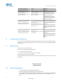 9
9
-
 10
10
-
 11
11
-
 12
12
-
 13
13
-
 14
14
-
 15
15
-
 16
16
-
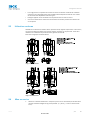 17
17
-
 18
18
-
 19
19
-
 20
20
-
 21
21
-
 22
22
-
 23
23
-
 24
24
-
 25
25
-
 26
26
-
 27
27
-
 28
28
-
 29
29
-
 30
30
-
 31
31
-
 32
32
-
 33
33
-
 34
34
-
 35
35
-
 36
36
-
 37
37
-
 38
38
-
 39
39
-
 40
40
-
 41
41
-
 42
42
-
 43
43
-
 44
44
-
 45
45
-
 46
46
-
 47
47
-
 48
48
-
 49
49
-
 50
50
-
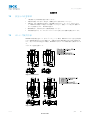 51
51
-
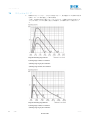 52
52
-
 53
53
-
 54
54
-
 55
55
-
 56
56
-
 57
57
-
 58
58
-
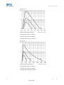 59
59
-
 60
60
-
 61
61
-
 62
62
-
 63
63
-
 64
64
-
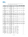 65
65
-
 66
66


en otros idiomas
- français: SICK GRTE18 Mode d'emploi
- English: SICK GRTE18 Operating instructions
- português: SICK GRTE18 Instruções de operação
- 日本語: SICK GRTE18 取扱説明書
Artículos relacionados
-
SICK GRTE18 Instrucciones de operación
-
-
-
-
-
-
-
SICK WT100-2 energetic Instrucciones de operación
-
-