SPX FLOW Ultra Ballast Pump Manual de usuario
- Tipo
- Manual de usuario

INSTRUCTION MANUAL
SE/EN/DE/FR/ES/IT
ORIGINAL INSTRUCTIONS/TRANSLATION OF ORIGINAL INSTRUCTIONS
READ AND UNDERSTAND THIS MANUAL PRIOR TO OPERATING OR SERVICING THIS
PRODUCT
Flexible Impeller Pump Ultra Ballast
F4B-11 12/24 V DC
IB-410 R05 (09/2017)

Garanti 3 år
Warranty 3 years
Garantie 3 Jahren
Garantie 3 ans
Garantía 3 años
Garanzia 3 anni
INDEX INDICE
Svenska .......................................................................................................................... 3
English ...........................................................................................................................7
Deutsch ........................................................................................................................11
Français ........................................................................................................................15
Español .........................................................................................................................19
Italiano ..........................................................................................................................23
SE: Besök www.spxflow.com för mer information om vår världsomspännande organisation, våra godkännanden, certifieringar
och lokala representanter. SPX FLOW, Inc. förbehåller sig rätten att ändra design och material utan föregående avisering.
Designelement, konstruktionsmaterial och dimensioner som beskrivs i denna bulletin gäller endast som information och skall
alltid bekräftas skriftligt för att vara gällande.
EN: For more information about our worldwide locations, approvals, certifications, and local representatives, please visit www.
spxflow.com. SPX FLOW, Inc. reserves the right to incorporate our latest design and material changes without notice or
obligation. Design features, materials of construction and dimensional data, as described in this bulletin,
are provided for your information only and should not be relied upon unless confirmed in writing.
DE: Für weitere Informationen über unsere weltweiten Standorte, Zulassungen, Zertifizierungen und unsere Vertreter vor
Ort, besuchen Sie bitte unsere Webseite: www.spxflow.com. Die SPX FLOW, Inc. behält sich das Recht vor, die neuesten
Konstruktions- und Werkstoffänderungen ohne vorherige Ankündigung und ohne Verpflichtung hierzu einfließen zu lassen.
Konstruktive Ausgestaltungen, Werkstoffe sowie Maßangaben, wie sie in dieser Mitteilung beschrieben sind, sind nur zur
Information. Alle Angaben sind unverbindlich, es sei denn, sie wurden schriftlich bestätigt.
FR: Pour plus d’information sur nos succursales internationales, nos approbations, nos certifications et nos représentants
locaux, veuillez consulter notre site Internet au www.spxflow.com. SPX FLOW, Inc. se réserve le droit d’incorporer nos plus
récents concepts ainsi que tout autre modification importante sans préavis ou obligation. Les éléments décoratifs, matériaux
de construction et les données dimensionnelles, tels qu’énoncés dans ce communiqué, sont fournis pour votre information
seulement et ne doivent pas être considérés comme officiels à moins d’avis contraire par écrit.
ES: Para más información sobre nuestras oficinas a nivel mundial, aprobaciones, certificaciones y representantes locales,
por favor visite www.spxflow.com. SPX FLOW, Inc. se reserva el derecho de incorporar nuestro diseño más reciente y
cambios materiales sin necesidad de notificación previa u obligación de ningún tipo. Características de diseño, materiales de
construcción y dimensiones, tal y como están descritas en este boletín, son proporcionadas sólo con fines informativos y no
deben ser usados como referencia a menos que sean confirmados por escrito.
IT: Per ottenere maggiori informazioni sulle nostre sedi nel mondo, autorizzazioni, certificazioni, e rappresentanti locali, potete
visitare il sito www.spxflow.com. La SPX FLOW, Inc. si riserva il diritto di apportare cambiamenti ai propri design e materiali
senza preavviso o vincolo. Le caratteristiche del design, i materiali di costruzione e i dati dimensionali, così come descritti
nel presente bollettino, sono forniti solo per vostra informazione e non saranno oggetto di obbligazione salvo autorizzazione
confermata per iscritto.
Made by SPX FLOW Johnson Pump®

3
Översättning av originalinstruktionerna
> Svenska
Ultra Ballast — Självsugande, flexibel impellerpump,
flänsmonterad till likströmsmotor 12/24 V
Typiska användningsområden
Ultra Ballast Pump är konstruerad för att
pumpa in vatten i ballasttankar.
Om den reverseras kan den även pumpa
vatten ut ur dessa.
Pumpen finns att tillgå med MC-97-
impeller samt med Polyuretan-impeller.
Teknisk beskrivning
Pumphus: Brons
Impeller: MC 97 gummi eller
Polyuretan
Tätning: Läpptätning,
NBR gummi
O-ring: NBR gummi
Anslutning: ½" invändig BSP/NPT
eller 1" slang (ø 25 mm)
Vätske
temperatur: Max +55°C
Motor: 0,25 kW, 12/24 V DC
med inbyggt termoskydd
Helkapslad
Reversibel
Axel: Rostfritt stål
Lager: Livstidssmorda, tätade
kullager
Motorn är gnistskyddad enligt ISO 8846
(Båtar - El-komponenter - Skyddad mot
antändning av omgivande brännbara
gaser).
Modellspecifikation
Typ Art nr
F4B-12 (BSP) Polyuretanimpeller 12V 10-24690-09
F4B-12 (BSP) Polyuretanimpeller 24V 10-24690-10
F4B-1207 (NPTF) Polyuretanimpeller 12V 10-24690-11
F4B-1207 (NPTF) Polyuretanimpeller 24V 10-24690-12
Tryck- och kapacitetsdata
(baserad på vatten vid 20°C och full
spänning till motor)
Installation och skötsel
Installation
Pumpen skall monteras på en torr, väl
ventilerad plats.
Pumpen kan monteras i vilket läge som
helst utan effektförlust. Emellertid
rekommenderas att pumphuvudet vänds
nedåt vid vertikal montering. Montera
motorn så nära kraftkällan som möjligt
för att erhålla full spänning.
Pumpen skall installeras så att den
skyddas från regn eller vattenspolning.
Vänligen uppmärksamma att pumphuset
kan vridas 180° i förhållande till motorn.
Detta ändrar flödesriktningen.
Vid användning av vakuumbrytare
monteras denna på uttaget på pump-
husets inloppssida. Vid användning av
tryckströmbrytare monteras denna på
uttaget på pumphusets utloppssida.
Hantera inte diesel eller andra mineraloljor
med denna pump. (För sådana vätskor
använd pump typ F4B-19).
Pumpen kan inte köras med stängt utlopp.
Risk för överhettning.
MC97
Tryck
Bar kPa psi l/min USGM 12V 24V
0 0 0,0 54 14,0 14,5 7
0,1 10 1,5 53 13,8 15 7, 5
0,3 30 4,4 49 12,7 16 8
0,6 60 8,7 44 11,4 18 9
0,9 90 13,1 38 9,9 20 10
1,2 120 17, 4 31 8,1 22 11
1,5 150 21,8 22 5,7 24 12
Polyuretan
Tryck
Bar kPa psi l/min USGM 12V 24V
0 0 0,0 52 13,5 12 4,8
0,1 10 1,5 50 13,0 12,5 4,9
0,3 30 4,4 47 12,2 12,7 5,5
0,6 60 8,7 39 10,1 15,5 6,2
0,9 90 13,1 29 7, 5 16,2 6,8
1,2 120 17, 4 15 3,9 17, 5 7, 3
Strömförbrukning

4Översättning av originalinstruktionerna
> Svenska
Ledningsdragning
Använd slang som inte veckar sig vid
böjning och som har tillräcklig material-
tjocklek för att inte sugas ihop på sugsidan
t.ex. armerade slangar.
Slangar skall dras så att en del vatten finns
kvar i pumphuset för att hålla impellern våt
för lättare start.
Använd en inloppssil för att förhindra
att skräp och fasta partiklar kommer in
i pumpen.
För att säkerställa en bra självsugnings-
förmåga skall samtliga kopplingar alltid
vara lufttäta.
Elektrisk installation
Pumpen ska installeras i enlighet med ISO
10133 (Båtar - Elektriska system- Klen-
spänningsinstallationer för likström). Obs!
Säkringen ska vara av gnistskyddad typ.
Motorn har ett termiskt överbelastning-
skydd som skyddar motorn från överhett-
ning. Skyddet återställs automatiskt då
motorn svalnat.
Om pumpen ansluts med separat jord-
ningskabel ska denna vara gul/grön och
anslutas till motorns fot.
Se kopplingsschema på följande sida för
korrekt installation.
Välj kabeldimension efter total kabellängd
enligt tabellen på följande sida.
Pumpen skall manövreras med en
polomkastare, genom en överspännings-
skyddad manöverpanel försedd med en
25 Amp/12V eller 15 Amp/24V brytare
eller säkring.
Kabelanslutningarna måste vara avtätade.
Obs! Innan installation med elektriskt
styrsystem, kontrollera att utrustningen
som ska användas har tillräcklig effekt för
motorns strömstyrka. Låg spänning kan
medföra att motorn överhettas.
Kopplingsschema
Kabelarea
(baserat på 3% spänningsfall)
Kabel-area Max kabel
längd* i m
12V 24V
2,5 mm2 # 14 AWG 2,7 11
4 mm2 # 12 AWG 4,4 17,6
6 mm2 # 10 AWG 6,6 26,3
10 mm2 # 6 AWG 11
16 mm2 # 4 AWG 17,6
25 mm2 # 2 AWG 27,4
* Kabellängden är det totala avståndet från batteriet
till pumpen och tillbaka till batteriet.
Det rekommenderas att använda ett relä för att
korta huvudledarna.
Drift
Ultra Ballast pump är reversibel så att
den både kan pumpa in vätskeballast och
sedan pumpa ut det vid behov. Som ett
alternativ kan man pumpa vätskeballast
från en tank till en annan och omvänt.
Vid behov av att öka ballastmängden slår
man över omkopplaren till fyllningsläge
och övervakar indikatorerna tills tanken
är full och stänger därefter av pumpen.
För att reducera ballastmängden, slå över
omkopplaren till dräneringsläge. Pumpen
reverseras för att pumpa tillbaka ballasten
överbord. Övervaka indikatorerna tills
tanken är tom och stäng av pumpen.
Samma förfaringssätt används för över-
föring av ballast mellan två tankar.
+
-
Svart
Pump
Säkring
Brytare
Art.nr 01-47196
Röd
Grön/Gul
Svart
Botten vy
av terminalen
8
6
5
4
2
1
Till motor röd
Till motor svart
Till batteri (+) pos.
Till batteri (-) neg.
824
6
Max 0,2 m

5
Översättning av originalinstruktionerna
> Svenska
Självsugningsförmåga (avser MC97-
impeller)
Pumpen är självsugande upp till 4 m för-
utsatt att sugledningen är absolut lufttät.
Obs! Pumpen är självsugande när
impellern är torr, men för att erhålla sug-
höjder upp till 4 m måste impellern vara
smord med den vätska som ska pumpas
eller Johnson Impeller Lubricant.
För permanent installation då sughöjden
överstiger 4 m bör en bottenventil
installeras för att vara säker på att pumpen
suger direkt vid start.
ANVÄND ALLTID JOHNSON IMPELLER
LUBRICANT (glycerin) för smörjning av
impellern. Använd aldrig smörjfett eller
mineraloljor.
Självsugningsförmåga (avser polyuretan)
Pumpen är självsugande upp till 1,5 m
förutsatt att sugledningen är absolut
lufttät. Obs! Pumpen är självsugande
när impellern är torr, men för att erhålla
sughöjder upp till 1,5 m måste inpellern
vara smord med den vätska som ska
pumpas eller Johnson Pump Impeller
Lubricant.
För permanent installation då sughöjden
överstiger 1,5 m bör en bottenventil
installeras för att vara säker på att pumpen
suger direkt vid start.
ANVÄND ALLTID JOHNSON IMPELLER
LUBRICANT (glycerin) för smörjning av
impellern. Använd aldrig smörjfett eller
mineraloljor.
Konstant drift
Vid kontinuerlig drift bör totala trycket inte
överstiga 0,6 bar (60 kPa, 8,5 psi). Max
omgivningstemp är +60°C.
Torrkörning
Kör inte pumpen torr mer än högst 30
sekunder. Torrkörning bränner upp impel-
lern och skadar tätningarna.
Varning. Explosionsrisk.
Pumpa inte bensin, lösningsmedel, thinner
eller andra lättantändliga vätskor. Hantera
inte högkoncentrerade eller organiska syror.
Varning. Explosionsrisk.
Använd aldrig en motor som på något vis
har manipulerats med och förlorat sin totala
inkapsling.
Temperatur
Max omgivningstemperatur: +60°C.
Impellerns livslängd är beroende av den
pumpade vätskans temperatur. Med tempe-
raturer mellan +5°C och +55°C kan normal
livstid förväntas. Vid högre eller lägre tempe-
ratur förkortas livslängden.
Varning. Motorns normala arbetstem-
peratur är ca. +80°C (temperatur på ytan)
vilket kan orsaka brännskador på huden.
Minusgrader
Dränera pumpen genom att lossa på locket.
Glykol kan användas som frostskyddsmedel,
men använd inte petroleumbaserade frost-
skyddsmedel.
Kassering/materialåtervinning
Efter produktens driftslivslängds slut, vänligen
kassera produkten i enlighet med gällande lag.
När det är tillämpligt, demontera produkten
och återvinn delarnas material.
Serviceinstruktioner (se sida 27-28)
Demontering
1. Lossa lockskruvarna (7), tag bort
locket (5) och O-ringen (6).
2. Drag ut impellern (3) med t.ex. en
polygriptång.
3. Lossa och tag bort muttrarna (8)
och brickorna (9) som håller pump-
huset. Drag bort pumphuset från
motorn.
4. Ta bort läpptätningen (4).
5. Ta inte isär motorn.

6Översättning av originalinstruktionerna
> Svenska
Montering
1. Fukta nya tätningen i såpvatten
(5% såpa), montera med läppen
riktad mot impellersidan.
2. Smörj motoraxeln med glycerin
eller dylikt. Montera pumphuset till
motorn.
3. Smörj pumphusets impellerutrymme
med Johnson Impeller Lubricant,
som finns levererat tillsammans med
reservimpellern. Smörj även lockets
yta.
Använd aldrig smörjfett eller mineral-
oljor för smörjning.
4. Montera impellern med en roterande
rörelse i pumpens rotationsriktning.
5. Smörj O-ringen med glycerin och
placera den i läge och skruva fast
locket.
Avfallshantering/materialåtervinning
Vid avfallshantering ska produkten lämnas
för destruktion/återvinning enligt gällande
lagstiftning. Vid tillämpliga fall
demonteras och sorteras produkten i
ingående materialfraktioner.
Impeller
Impellern, art.nr. 09-824P-1 (MC-97)
eller 09-824P-2 /polyuretan), är en
mycket viktig säkerhetsdetalj och bör
bytas varje år. Använd Johnson
originalimpeller.
Smörj alltid impellern vid utbyte med
Johnson Impeller Lubricant, levererat
tillsammans med reservdelssatsen.
Tillbehör
Polarity Reversing Switch Kit
Art, nr. 09-47196

7
Original instructions
> English
Ultra Ballast — Self-priming, flexible impeller pump
flange mounted to DC motor 12/24 V
Typical applications
The Ultra Ballast Pump has been designed
to pump water into ballast tanks. When
reversed it will also pump water out of them.
The pump can be obtained with an MC-97
impeller and a Polyurethane impeller.
Design features
Body: Bronze
Impeller: MC 97 rubber or
polyurethane
Seal: Lip seal, NBR rubber
or Polyurethane
O-ring: NBR rubber
Connection: ½” Internal BSP/NPT
or 1” hose (ø 25 mm)
Liquid
temperature: Max +55°C
Motor: 0,25 kW, 12/24 V DC
with built in thermal
protection
Total enclosed
Reversible
Shaft: Stainless steel
Bearings: Permanent lubricated,
sealed, ball bearings
The motor is ignition protected according
to ISO 8846 (Small craft
- Electrical devices - Protection against
ignition of surrounding flammable gases).
Type designation
Type Part No
F4B-12 (BSP) polyurethane impeller 12V 10-24690-09
F4B-12 (BSP) polyurethane impeller 24V 10-24690-10
F4B-1207 (NPTF) polyurethane impeller 12V 10-24690-11
F4B-1207 (NPTF) polyurethane impeller 24V 10-24690-12
Pressure and capacity data
(based on water at 20°C and at nomi-
nal voltage of the motor)
Installation and maintenance
Installation
Pump should be mounted in a dry, cool
ventilated location.
Pump may be mounted in any position
without loss of efficiency; however, it is
suggested that the pump head be down if
vertical mounting is desired. Mount motor
as close as possible to power source to
obtain full voltage.
The pump should be installed so that the
motor is protected from rain, wash down
or bilge water.
Please note that pump body can be turned
180° in relation to motor. This changes
flow direction.
When using a vac-on-switch, mount it
on the connection on the inlet side of the
pump. When using a pressure switch,
mount it on the connection on the outlet
side of the pump.
Don’t handle diesel fuel or other mineral
oils with this pump. (For these liquids use
pump type F4B-19)
This pump cannot run against a closed
outlet. Risk for overheating.
MC97
Pressure
Bar kPa psi l/min USGM 12V 24V
0 0 0,0 54 14,0 14,5 7
0,1 10 1,5 53 13,8 15 7, 5
0,3 30 4,4 49 12,7 16 8
0,6 60 8,7 44 11,4 18 9
0,9 90 13,1 38 9,9 20 10
1,2 120 17, 4 31 8,1 22 11
1,5 150 21,8 22 5,7 24 12
Polyurethane
Pressure
Bar kPa psi l/min USGM 12V 24V
0 0 0,0 52 13,5 12 4,8
0,1 10 1,5 50 13,0 12,5 4,9
0,3 30 4,4 47 12,2 12,7 5,5
0,6 60 8,7 39 10,1 15,5 6,2
0,9 90 13,1 29 7, 5 16,2 6,8
1,2 120 17, 4 15 3,9 17, 5 7, 3
Ampere

8Original instructions
> English
Plumbing
Use hose that does not kink when bent,
and also with sufficient wall thickness
preventing collapse when used on suction
side, eg. reinforced hoses.
Hoses should be routed so that some
water will remain in pump body to wet
impeller for easy start up.
Use a strainer at intake hose to prevent
from trash and solids entering the pump.
In order to ensure good priming always
keep connections airtight.
Electrical installation
The pump must be installed according
to ISO 10133 (Small craft - Electrical
system - Extra low voltage DC installation
for continuous current). Note: The fuse
must be ignition protected.
The motor is equipped with built in ther-
mal protection to prevent the motor from
overheating. The protection is automati-
cally restored when the motor is cooled.
If the pump is connected with separate
earth lead, this should be yellow/green
and connected to the motor base.
See the wiring table for correct installation.
Choose wire size in accordance with total
wire length (see table beside).
The pump should be operated by a Polarity
Reversing switch, through an over current
protected distribution panel fitted with a
25 Amp/12V or 15 Amp/24V breaker
or fuse.
The wire connections must be sealed.
Note: Before installation with electrical
control systems, check that equipment
to be used is of sufficient rated capacity
to accept ampere draw of motor.
Wiring Table
+
-
Black
Pump
Terminal fuse or overload
Protected Distribution Panel
Polarity Reversing
Switch
pt.no 01-47196
Red
Green/Yellow
Black
Bottom view
of terminal
arrangement
8
6
5
4
2
1
To motor red
To motor black
To battery (+) pos.
To battery (-) neg.
824
6
Max 0,2 m
Wiring dimensions
(based on 3% voltage drop)
Wire size Max wire
lenght* in m
12V 24V
2,5 mm² # 14 AWG 2,7 11
4 mm² # 12 AWG 4,4 17,6
6 mm² # 10 AWG 6,6 26,3
10 mm² # 6 AWG 11
16 mm² # 4 AWG 17,6
25 mm² # 2 AWG 27,4
*The wire length is the total distance from
the battery to the pump and back to the
battery. It is recommended to use a relay to
shorten the main leaders.
Operation
The Ultra Ballast pump is reversible so
it can both add liquid ballast and then
pump it overboard when needed. As an
alternative you may pump liquid ballast
from one tank to another and reversed.
At need for adding ballast you flip the
switch to fill position and watch for indica-
tors that tank is full, then switch pump off.
To reduce ballast, flip switch to drain
position. The pump will reverse to pump
ballast back over board. Watch indicator
for an empty tank and switch pump off.
The same operation is used for ballast
transfer between two tanks.

9
Original instructions
> English
Self-priming (refers MC97-impeller)
Pump is self-priming up to 4 m. Intake lines
must be air-tight to ensure self-priming.
Note: Pump will prime when impeller is dry
but suction lift up to 4 m is only obtainable
when impeller is lubricated with liquid being
pumped or Johnson Impeller Lubricant.
For permanent installations where suction
lift exceeds 4 m, a foot valve should be
used to assure priming on start up.
ALWAYS USE JOHNSON IMPELLER
LUBRICANT (glycerin) for impeller lubri-
cation. Never use grease or mineral oils.
Self-priming (refers polyurethane impeller)
The pump is self-priming up to 1.5 metres
provided that the suction pipe is absolutely
airtight. Note! The pump is self-priming
when the impeller is dry, but to obtain
suction heads up to 1.5 metres the impeller
must be lubricated with the liquid to be
pumped or Johnson Impeller Lubricant. For
a permanent installation where the suction
head exceeds 1.5 metres a foot valve
should be fitted to ensure the pump can
provide suction immediately after starting.
ALWAYS USE JOHNSON IMPELLER
LUBRICANT (glycerin) for lubricating the
impeller. Never use grease or mineral oils.
Continuous duty
For continuous duty 0,6 bar (60 kPa, 8,5
psi) maximum head is permissible. Max
ambient temp is +60°C.
Dry running
Do not run dry for more than 30 seconds.
Lack of liquid will burn the impeller and
damage the seals.
Caution. Explosion Hazard.
Do not pump gasoline, solvents, thinners
or other flammable liquids.
Do not handle highly concentrated or
organic acids.
Caution. Explosion Hazard.
Never operate a motor which in any way
has been manipulated and lost it’s full
enclosure.
Temperature
Max ambient temperature: +60°C.
The life of the impeller depends on the
temperature of liquid being pumped. Tem-
peratures between +5°C and +55°C give
normal life. Higher or lower temperature
will reduce the life.
Caution.
The normal working temperature of the
motor may reach approx. +80°C (surface
temperature) which may burn your skin.
Freezing weather
Drain unit by loosening the end cover.
Glycol based anti-freezes can be used but
do not use petroleum based anti-freeze
compounds.
Waste handling/material recycling
At the product’s end of life please dispose
of the product according to applicable law.
Where applicable please disassemble the
product and recycle the parts material.
Service instructions
(see page27-28)
Disassembly
1. Back off the endcover screws (7), re-
move the endcover (5) and O-ring (6).
2. Pull out the impeller (3) using a slip
joint plier.
3. Back off and remove the nuts (8)
and washers (9) holding the body.
Separate the body from the motor.
4. Remove the lip seal (4).
5. Do not disassemble the motor.

10 Original instructions
> English
Assembly
1. Moisten the new lip seal with soapy
water (5% soft soap), mount the
seal with the lip facing towards the
impeller.
2. Lubricate the motor shaft with
glycerin of the like. Fit the body to
the motor.
3. Lubricate inside the pump body
where the impeller should be placed
with Johnson Impeller Lubricant,
provided with the spare Impeller.
Also lubricate the surface of the
end cover. Never use grease or
mineral oils for lubrication.
4. Fit the impeller with a rotating
movement in the intended direction
of the pump rotation.
5. Lubricate the O-ring with glycerin
and fit it in its position and fasten
the end cover.
Waste handling/
material recycling
At the products end of life, please dis-
pose of the product according to ap-
plicable law. Where applicable, please
disassemble the product and recycle
the parts material.
Impeller
The impeller, pt.no. 09-824P-1 (MC-
97) or 09-824P-2 (polyurethane), is
a very important security device and
should be replaced every year with a
Johnson original impeller.
Always lubricate Impeller at replace-
ment with Johnson Impeller Lubricant,
provided with the spare kit.
Accessories
Polarity Reversing Switch Kit
Part No. 09-47196

11
Übersetzung der Original-Betriebanleitungen
> Deutsch
Ultra Ballast — Selbstansaugende, flexible Impellerpumpe
mit Gleichstrom motor 12/24 V
Typische Anwendungen
Die Ultra Ballast-Pumpe wurde zum
Pumpen von Wasser in Ballasttanks
entwickelt. Beim Umdrehen kann damit
auch Wasser aus Ballasttanks gepumpt
werden.
Die Pumpe ist mit einem MC-97-Laufrad
und einem Polyurethan-Laufrad erhältlich.
Technische Daten
Gehäuse: Bronze
Impeller: MC 97-Gummi oder
Polyurethan
Abdichtung: Lippendichtung,
NBR-Gummi
O-Ring: NBR-Gummi
Anschluss: ½” innerer BSP/NPT-
Anschluss oder 1”
Schlauch (ø 25 mm)
Flüssigkeits-
temperatur: Max +55°C
Motor: 0,25 kW, 12/24 V DC
mit eingebautem
thermischen
Überlastungsschutz
Insgesamt eingeschlos-
sen
Umschaltbar
Welle: Edelstahl
Lager: Dauergeschmiert,
gedichtet, Kugellager
Der Elektromotor ist nach ISO 8846
funkengeschützt (für Kleinschiffe -
elektrische Ausführung - Schutz gegen
Entzündung umgebender, entflammbarer
Gase).
Modellvarianten
Typ Artikel Nr.
F4B-12 (BSP) Polyurethan-Laufrad 12V 10-24690-09
F4B-12 (BSP) Polyurethan-Laufrad 24V 10-24690-10
F4B-1207 (NPTF) Polyurethan-Laufrad 12V 10-24690-11
F4B-1207 (NPTF) Polyurethan-Laufrad 24V 10-24690-12
Druck- und Leistungsdaten
(basierend auf einer Wassertemperatur
von 20°C und max. elektrischer Span-
nung für den Motor)
Strom-aufnahme
Montage und Wartung
Montage
Die Pumpe sollte in einer trockenen,
kühlbelüfteten Lage montiert werden.
Die Pumpe kann in beliebiger Lage,
ohne Beeinträchtigung der Leistung,
montiert werden. Es wird jedoch emp-
fohlen, falls die Pumpe senkrecht einge-
baut wird, diese mit dem Pumpenkopf
nach unten einzubauen. Die Pumpe ist
so nahe wie möglich an der Stromver-
sorgung zu montieren, um Spannungs-
verluste zu vermeiden.
Bei der Installation der Pumpe muss
darauf geachtet werden, dass der Motor
vor Regen- oder Spritzwasser geschützt
ist.
Bitte beachten Sie, dass die Pumpe um
180° in Bezug auf den Motor gedreht
werden kann. Dies ändert die Flussrich-
tung.
Wenn Sie einen Vakuumschalter
verwenden, montieren Sie ihn an dem
Anschluss an der Einlaufseite der
Pumpe. Wenn Sie einen Druckschalter
MC97
Druck
Bar kPa psi l/min USGM 12V 24V
0 0 0,0 54 14,0 14,5 7
0,1 10 1,5 53 13,8 15 7, 5
0,3 30 4,4 49 12,7 16 8
0,6 60 8,7 44 11,4 18 9
0,9 90 13,1 38 9,9 20 10
1,2 120 17, 4 31 8,1 22 11
1,5 150 21,8 22 5,7 24 12
Polyurethan
Druck
Bar kPa psi l/min USGM 12V 24V
0 0 0,0 52 13,5 12 4,8
0,1 10 1,5 50 13,0 12,5 4,9
0,3 30 4,4 47 12,2 12,7 5,5
0,6 60 8,7 39 10,1 15,5 6,2
0,9 90 13,1 29 7, 5 16,2 6,8
1,2 120 17, 4 15 3,9 17, 5 7, 3
Stromverbrauch

12 Übersetzung der Original-Betriebanleitungen
> Deutsch
verwenden, montieren Sie ihn an dem
Anschluss an der Auslaufseite der
Pumpe.
Dieselkraftstoff oder andere Mineralöle
dürfen mit dieser Pumpe nicht befördert
werden. (Für diese Flüssigkeiten ver-
wenden Sie die Pumpe F4B-19)
Diese Pumpe kann nicht mit einem ge-
schlossenen Auslauf betrieben werden,
da dies Überhitzung verursachen kann.
Rohrleitungen
Verwenden Sie einen Schlauch, der
beim Biegen nicht knickt und eine aus-
reichende Wanddicke hat, damit er bei
der Benutzung an der Ansaugseite nicht
staucht, z.B. Panzerschläuche.
Die Schläuche sollten so geführt wer-
den, dass etwas Wasser im Pumpenge-
häuse bleibt, um den Impeller für einen
leichten Anlauf anzufeuchten.
Verwenden Sie am Einlaufschlauch
einen Filter, damit weder Abfall noch
Feststoffe in die Pumpe gelangen.
Um ein gutes Ansaugen zu gewähr-
leisten, sollten die Anschlüsse immer
luftdicht sein.
Elektrische Installation
Die Pumpe muss nach den Regeln von
ISO 10133 (Kleinboote - Elektrosystem
- extra niedrige Spannung bei Gleich-
strominstallation - für gleichmäßigen
Stromfluss) installiert werden. Achtung:
Die Sicherung muss funkengeschützt
sein.
Der Motor hat einen eingebauten ther-
mischen Überlastungsschutz, der den
Motor vor Überhitzung schützt. Wenn
der Motor sich abgekühlt hat, schaltet
sich der Überlastungsschutz automa-
tisch wieder ab.
Wenn die Pumpe mit einer separaten
Erdleitung versehen ist, sollte diese
gelb/grün sein und an den Motorhalter
angeschlossen werden.
Zur korrekten Installation beachten Sie
bitte den Schaltplan.
Beachten Sie die Kabelquerschnitte im
Zusammenhang mit der erforderlichen
Kabellänge (sehen Sie die Tabelle).
Die Pumpe sollte von einem Polaritäts-
Umschalter über eine überstrom-
geschützte Verteileranlage mit 25
Amp/12V oder 15 Amp/24V Brecher
oder Sicherung betrieben werden.
Die Kabelanschlüsse müssen isoliert
sein.
Achtung: Bei Installationen mit einem
elektrischen Steuersystem ist sicherzu-
stellen, dass das Zubehör für die Strom-
aufnahme des Motors ausgelegt ist.
Schaltplan
+
-
Schwarz
Pumpe
Hauptsicherung oder überstrom-
geschützte Verteileranlage
Polaritäts-
Umschalter
Teilnr. 01-47196
Rot
Grün/Gelb
Schwarz
Unteransicht
der Anschlüsse
8
6
5
4
2
1
Zum Motor rot
Zum Motor schwarz
Zur Batterie (+) plus.
Zur Batterie (-) minus
824
6
Max 0,2 m
Tabelle Kabelanschlüsse
(basierend auf 3% Spannungsverlust)
Kabelquerschnitt Max. Kabel
Länge* in m
12V 24V
2,5 mm² # 14 AWG 2,7 11
4 mm² # 12 AWG 4,4 17,6
6 mm² # 10 AWG 6,6 26,3
10 mm² # 6 AWG 11
16 mm² # 4 AWG 17,6
25 mm² # 2 AWG 27,4
* Die Kabellänge ist die komplette Länge
von der Batterie zur Pumpe und zurück zur
Batterie.
Es wird empfohlen, ein Relais zu verwenden,
um die Hauptleitungen zu verkürzen.

13
Übersetzung der Original-Betriebanleitungen
> Deutsch
Betrieb
Die Ultra Ballast-Pumpe ist umschaltbar,
so dass Flüssigballast sowohl hinzugefügt
als bei Bedarf auch über Bord gepumpt
werden kann. Alternativ können Sie
Flüssigballast aus einem Tank in einen
anderen und umgekehrt pumpen.
Wenn Sie Ballast hinzufügen müssen,
drehen Sie den Schalter in die Füllstellung
und schalten Sie die Pumpe aus, wenn die
Anzeige den vollen Tank anzeigt.
Um Ballast zu vermindern, drehen Sie
den Schalter in die Abflussstellung. Die
Pumpe wird den Ballast wieder über Bord
pumpen. Schalten Sie die Pumpe aus,
wenn die Anzeige den leeren Tank anzeigt.
Derselbe Vorgang wird zur Übertragung
des Ballasts zwischen den Tanks ver-
wendet.
Selbstansaugen (bezieht sich auf
MC97-Laufrad)
Die Pumpe ist bis zu 4 m selbstansau-
gend. Die Ansaugleitungen müssen
jedoch absolut luftdicht sein. Achtung:
Die Pumpe saugt an, wenn der Impeller
trocken ist, aber eine Ansaughöhe von
bis zu 4 m wird nur erreicht, wenn der
Impeller mit der beförderten Flüssigkeit
oder dem Johnson Impeller Lubricant
geschmiert ist.
Bei fester Installation und Ansaughöhen
von über 4 m sollte ein Fußrückschlag-
ventil in die Saugleitung montiert werden,
um das Ansaugen der Pumpe sofort beim
Einschalten zu gewährleisten.
Zum Schmieren des Impellers VERWEN-
DEN SIE IMMER DEN JOHNSON IM-
PELLER LUBRICANT SCHMIERSTOFF
(Glyzerin). Niemals Schmierfett oder
Mineralöle verwenden.
Selbstansaugung (bezieht sich auf
Polyurethan-Laufrad)
Die Pumpe ist bis zu 1,5 m selbstansau-
gend (vorausgesetzt, die Ansaugleitung
ist vollständig luftdicht). Hinweis! Die
Pumpe ist selbstansaugend, wenn das
Laufrad trocken ist.
Um Saughöhen von bis 1,5 m zu erhalten,
muss das Laufrad mit der zu pumpenden
Flüssigkeit oder mit Lufrad-Schmiermittel
von Johnson geschmiert werden.
VERWENDEN SIE STETS LAUFRAD-
SCHMIERMITTEL VON JOHNSON
(Glycerin) zum Schmieren des Laufrads.
Niemals Schmierfett oder Mineralöle
verwenden!
Dauerbetrieb
Für Dauerbetrieb ist ein maximaler Druck
von 0,6 bar (60 kPa, 8,5 psi) zulässig. Max.
Umgebungstemperatur beträgt +60°C.
Trockenlaufen
Die Pumpe nicht länger als 30 Sekunden
trocken laufen lassen. Durch
Trockenlauf wird der Impeller verbrannt
und die Dichtungen beschädigt.
Vorsicht. Explosionsgefahr.
Kein Benzin, keine Lösungsmittel, Verdün-
nungsmittel oder andere entflammbare
Flüssigkeiten pumpen.
Keine hochkonzentrierten oder orga-
nischen Säuren behandeln
Vorsicht. Explosionsgefahr.
Niemals einen Motor betätigen, der in
irgendeiner Weise modifiziert ist und seine
vollständige Verkleidung verloren hat.
Temperatur
Max. Umgebungstemperatur: +60°C.
Die Lebensdauer des Impellers hängt von
der gepumpten Flüssigkeit ab. Tempera-
turen zwischen +5°C und +55°C geben
eine normale Lebensdauer, höhere oder
niedrigere Temperaturen reduzieren die
Lebensdauer.

14 Übersetzung der Original-Betriebanleitungen
> Deutsch
Vorsicht.
Die normale Betriebstemperatur des
Motors beträgt etwa +80°C (Oberflä-
chentemperatur), die Ihre Haut verbren-
nen kann.
Bei Frostgefahr
Die Pumpe entleeren, indem der Deckel
abgeschraubt wird. Auf Glykol basieren-
de Frostschutzmittel können verwendet
werden, aber keine Frostschutzmittel, die
auf Mineralöl basieren.
Abfallbehandlung/
Materialrecycling
Am Ende der Lebensdauer des Produkts
behandeln Sie es in Übereinstimmung mit
dem gültigen Gesetz.
Bei Bedarf bauen Sie das Produkt ausei-
nander und verwenden Sie das Material
der Einzelteile.
Wartungsanleitungen
(siehe Seite 27-28)
Demontage
1. Die Deckelschrauben (7) lösen und
den Deckel (5) und den O-Ring (6)
entfernen.
2. Den Impeller (3) mit einer Wasser-
pumpenzange herausziehen.
3. Die Muttern (8) und die Scheiben
(9), die das Pumpengehäuse halten,
abschrauben. Das Pumpengehäuse
vom Motor abnehmen.
4. Die Lippendichtung (4) entfernen.
5. Den Motor nicht demontieren.
Montage
1. Die neue Lippendichtung mit etwas
seifigem Wasser (5% weiche Seifen-
lösung) befeuchten, die Dichtung mit
der Lippe zum Impeller einbauen.
2. Schmieren Sie die Motorwelle mit
dem gleichen Glyzerin ein. Bauen
Sie das Gehäuse an den Motor an.
3. Schmieren Sie das Innere der
Pumpe am Einbauort des Impellers
mit dem Johnson Impeller
Lubricant ein, wenn der Ersatz-
impeller eingebaut ist. Schmieren
Sie auch die Oberfläche des
Deckels.
Niemals Schmierfett oder Mineral-
öle zum Schmieren verwenden.
4. Den Impeller leicht drehend in
Drehrichtung der Pumpe einsetzen.
5. Den O-Ring mit Glyzerin einfetten,
einsetzen und den Deckel montie-
ren.
Entsorgung/Recycling
Nach Lebensdauerende entsorgen
Sie die Pumpe nach den örtlichen
Vorschriften.
Nach Möglichkeit demontieren Sie Teile
der Pumpe um sie dem Recycling-
Process zuzuführen.
Impeller
Der Impeller, Teilenr. 09-824P-1 (MC-
97) oder 09-824P-2 (Polyurethan), ist
ein sehr wichtiges Teil für die Sicherheit
und sollte jährlich durch einen neu-
en original Johnson Impeller ersetzt
werden.
Schmieren Sie den Impeller beim Aus-
tausch immer mit dem Johnson Impeller
Lubricant, der im Ersatzteilset einge-
schlossen ist.
Zubehör
Polarity Reversing Switch Kit
Part No. 09-47196

15
Traduction du manuel d'instruction d'origine
> Français
Ultra Ballast — Pompe auto-amorçable à rotor flexible
fonctionnant sur courant continu 12/24 V
Types d’applications
La pompe Ultra Ballast Pump a été
conçue pour pomper l’eau dans les
ballasts. Quand elle est inversée, elle va
également pomper l’eau hors de ceux-ci.
La pompe est disponible avec une roue
MC-97 ou une roue en polyuréthane.
Caractéristiques techniques
Corps: Bronze
Rotor: MC 97 caoutchoucou
polyuréthane
Joint: Joint à lèvre, caoutchouc
nitrile
Joint torique: caoutchouc nitrile
Raccords: 1/2” Intérieur BSP/NPT
ou durite 1” (ø 25 mm)
Température
du liquide: Max +55°C
Moteur: 0,25 kW, 12/24 V DC
avec protection
thermique intégrée
Totalement protégé
Réversible
Hélice: Acier inoxydable
Roulements: Roulements à billes
étanche, lubrifié en
permanence
Le moteur est antidéflagrant selon la
norme ISO 8846 (Navires de plaisance
- Equipements électriques - Protection
contre l’inflammation des gaz inflam-
mables environnants).
Désignation du modèle
Modèle Référence
F4B-12 (BSP) roue en polyuréthane 12V 10-24690-09
F4B-12 (BSP) roue en polyuréthane 24V 10-24690-10
F4B-1207 (NPTF) roue en polyuréthane 12V 10-24690-11
F4B-1207 (NPTF) roue en polyuréthane 24V 10-24690-12
Caractéristiques de pression et de
débit
(basées sur une eau à 20°C et une
tension maximale des batteries)
Installation et maintenance
Installation
La pompe doit être installée dans un
endroit sec et fraîchement ventilé.
La pompe peut être montée dans n’importe
quelle position sans pour autant affecter
son efficacité; cependant, nous recom-
mandons d’installer la pompe la tête en
bas si une fixation verticale est désirée.
Installer le moteur aussi près que possible
de la source d’alimentation électrique afin
d’éviter les chutes de tension.
La pompe doit être installée de manière à
ce que le moteur soit protégé de la pluie
et de l’eau de lavage.
Veuillez SVP noter que le corps de la
pompe peut être orienté à 180° par rapport
au moteur. Ceci change le sens du flux.
Dans le cas où un contacteur à dépression
st utilisé, il doit être monté sur le raccord
du côté aspiration de la pompe. Quand
on utilise un pressostat, il doit être installé
sur le raccord situé du côté refoulement
de la pompe.
N’utilisez pas la pompe pour du carburant
diesel ou d’autres huiles minérales. (Pour
MC97
Pression
Bar kPa psi l/min USGM 12V 24V
0 0 0,0 54 14,0 14,5 7
0,1 10 1,5 53 13,8 15 7, 5
0,3 30 4,4 49 12,7 16 8
0,6 60 8,7 44 11,4 18 9
0,9 90 13,1 38 9,9 20 10
1,2 120 17, 4 31 8,1 22 11
1,5 150 21,8 22 5,7 24 12
Polyuréthane
Pression
Bar kPa psi l/min USGM 12V 24V
0 0 0,0 52 13,5 12 4,8
0,1 10 1,5 50 13,0 12,5 4,9
0,3 30 4,4 47 12,2 12,7 5,5
0,6 60 8,7 39 10,1 15,5 6,2
0,9 90 13,1 29 7, 5 16,2 6,8
1,2 120 17, 4 15 3,9 1 7, 5 7, 3
Consommation électrique

16 Traduction du manuel d'instruction d'origine
> Français
ces liquides utilisez la pompe modèle
F4B-19)
Cette pompe ne peut pas fonctionner
avec un refoulement bouché. Risque de
surchauffe.
Plomberie
Utilisez un tuyau qui ne s’étrangle pas
lorsqu’il est coudé et également avec
une épaisseur de paroi suffisante, par
exemple des tuyaux renforcés, pour éviter
une déformation quand utilisé du côté
aspiration.
Les tuyaux doivent être installés de
manière à ce qu’un peu d’eau restera dans
le corps de la pompe pour humidifier le
rotor pour un démarrage facile.
Utilisez une crépine pour éviter que des
détritus et des objets solides n’entrent
dans la pompe.
De manière à garantir un bon amorçage,
gardez toujours vos raccords étanches
`l’air.
Installation électrique
La pompe doit être installée selon la norme
ISO 10133 (Petits navires -- Systèmes
électriques -- Installations à très basse
tension à courant continu). Important: Le
fusible doit être antidéflagrant.
Le moteur est équipé d’une protection
thermique intégrée afin de le protéger
contre une surchauffe. La protection est
automatiquement réarmée dès que le
moteur a refroidi.
Si un fil de mise à terre est raccordé à la
pompe, il doit être de couleur jaune/verte
et raccordé à la base du moteur.
Voir schéma de câblage pour une instal-
lation correcte.
Choisissez la section des fils d’alimenta-
tion en fonction de leur longueur totale
(voir tableau suivante).
La pompe doit être commandée par
un commutateur d’inversion de polarité
monté sur un tableau de distribution
protégé contre une surintensité par un
coupe-circuit ou un fusible 25 A/12V
ou 15 A/24V.
Les raccordements des fils doivent être
rendus étanches.
Important: Avant toute installation avec
un système de commande électrique,
vérifiez que le matériel qui va être utilisé
peut supporter le courant demandé par
le moteur.
Schéma de câblage
+
-
Noir
Pumpe
Fusible ou Tableau de Distribution
Protégé contre une surintensité
Commutateur d’Inversion
de Polarité
Pièce No. 01-47196
Rouge
Vert/Jaune
Noir
Vue de dessous
de la disposition
des bornes
8
6
5
4
2
1
A moteur rouge
A moteur noir
A la batterie (+) pos.
A la batterie (-) neg.
824
6
Max 0,2 m
Sections des fils
(basée sur une chute de tension de 3%)
Section Fil Max longueur* en m
12V 24V
2,5 mm² # 14 AWG 2,7 11
4 mm² # 12 AWG 4,4 17,6
6 mm² # 10 AWG 6,6 26,3
10 mm² # 6 AWG 11
16 mm² # 4 AWG 17,6
25 mm² # 2 AWG 27,4
*La longueur du fil est la distance totale
de la batterie à la pompe et du retour de la
pompe à la batterie.
Il est recommandé d’utiliser un relais afin de
raccourcir les fils d’alimentation.
Utilisation
La pompe Ultra Ballast est réversible de
manière à ce qu’elle puisse aussi bien
ajouter du liquide de ballast que le pomper
par-dessus bord si nécessaire. Comme
alternative, vous pouvez pomper le liquide

17
Traduction du manuel d'instruction d'origine
> Français
Les raccordements des fils doivent être
rendus étanches.
Important: Avant toute installation avec
un système de commande électrique,
vérifiez que le matériel qui va être utilisé
peut supporter le courant demandé par
le moteur.
Schéma de câblage
+
-
Noir
Pumpe
Fusible ou Tableau de Distribution
Protégé contre une surintensité
Commutateur d’Inversion
de Polarité
Pièce No. 01-47196
Rouge
Vert/Jaune
Noir
Vue de dessous
de la disposition
des bornes
8
6
5
4
2
1
A moteur rouge
A moteur noir
A la batterie (+) pos.
A la batterie (-) neg.
824
6
Max 0,2 m
Sections des fils
(basée sur une chute de tension de 3%)
Section Fil Max longueur* en m
12V 24V
2,5 mm² # 14 AWG 2,7 11
4 mm² # 12 AWG 4,4 17,6
6 mm² # 10 AWG 6,6 26,3
10 mm² # 6 AWG 11
16 mm² # 4 AWG 17,6
25 mm² # 2 AWG 27,4
*La longueur du fil est la distance totale
de la batterie à la pompe et du retour de la
pompe à la batterie.
Il est recommandé d’utiliser un relais afin de
raccourcir les fils d’alimentation.
Utilisation
La pompe Ultra Ballast est réversible de
manière à ce qu’elle puisse aussi bien
ajouter du liquide de ballast que le pomper
par-dessus bord si nécessaire. Comme
alternative, vous pouvez pomper le liquide
de ballast d’un réservoir vers un autre
et vice-versa. Si vous devez ajouter du
liquide de ballast vous basculez le com-
mutateur dans la position de remplissage
et surveillez l’indicateur jusqu’à ce que
le réservoir soit plein, ensuite éteignez
la pompe.
Pour réduire le ballast, basculez le
commutateur sur position de vidange.
La pompe va s’inverser pour pomper
le ballast par-dessus bord. Surveillez
l’indicateur jusqu’à ce que le réservoir
soit vide et éteignez la pompe.
La même opération est utilisée pour
transférer le ballast entre deux réservoirs.
Autoamorçage fait référence à la
roue MC97)
La pompe est autoamorçante jusqu’à 4
m. Le tuyau d’aspiration doit être étanche
à l’air pour garantir l’autoamorçage.
Important: La pompe s’amorcera même
si le rotor est sec mais dans le cas d’une
hauteur manométrique de succion attei-
gnant 4 m, le rotor doit être lubrifié avec
le liquide à pomper ou avec le lubrifiant
Johnson Impeller Lubricant.
Pour des installations permanentes où
la hauteur manométrique de succion
dépasse 4 m, un clapet de pied doit être
utilisé pour garantir l’amorçage lors du
démarrage.
UTILISEZ TOUJOURS LE LUBRIFIANT
JOHNSON IMPELLER LUBRICANT
(glycérine) pour la lubrification de rotor.
N’utilisez jamais de graisse ou d’huiles
minérales.
Auto-amorçante (fait référence à
la roue en polyuréthane)
La pompe est auto-amorçante jusqu'à 1,5
mètre à condition que le tuyau d'aspiration
soit totalement hermétique. Attention !
La pompe est auto-amorçante lorsque
la roue est sèche, mais la roue doit être
lubrifiée avec le liquide destiné à être
pompé ou le Johnson Impeller Lubricant
pour que l'aspiration atteigne 1,5 mètre.
Pour une installation permanente où la
hauteur d'aspiration est supérieure à 1,5
mètre, un clapet de pied doit être installé
pour s'assurer que la pompe puisse fournir
de l'aspiration au démarrage.
UTILISEZ TOUJOURS JOHNSON
IMPELLER LUBRICANT (glycérine)
pour lubrifier la roue. N'utilisez jamais de
graisse ou d'huiles minérales.
Fonctionnement permanent
La pression admise ne doit pas excéder
0,6 bar (60 kPa, 8,5 psi) au maximum lors
du fonctionnement en continu. La tempé-
rature ambiante maximale est de +60°C.
Fonctionnement à vide
Ne pas faire fonctionner la pompe à
vide pendant plus de 30 secondes. Une
absence de liquide brûlera le rotor et
endommagera les joints.
Attention. Danger d’explosion.
Ne pas pomper d’essence, de solvants, de
diluants ou d’autres liquides inflammables.
Ne pas pomper des acides hautement
concentrés ou organiques.
Attention. Danger d’explosion.
Ne jamais faire fonctionner un moteur qui
a été trafiqué d’une quelconque manière
ou qui a perdu son enveloppe complète.
Température
Température ambiante max.: +60°C.
La durée de vie du rotor dépend de
la température du liquide pompé. Des
températures comprises entre +5°C et
+55°C correspondent à une durée de vie
normale. Des températures supérieures
ou inférieures en raccourciront la durée
de vie.

18 Traduction du manuel d'instruction d'origine
> Français
Attention.
La température normale de fonctionne-
ment du moteur est d’environ +80°C
(température de la surface) ce qui peut
brûler votre peau.
Températures ambiantes inférieures
à 0°C
Vidanger la pompe en dévissant le cou-
vercle du fond. Des antigels à base de
glycol peuvent être utilisés mais ne jamais
utiliser d’antigels à base de pétrole.
Traitement des déchets /recyclage
du matériel
A la fin de la vie du produit, veuillez SVP
traiter les déchets selon la loi en vigueur.
Là où c’est possible, veuillez SVP démon-
ter le produit et recycler les différentes
parties de matériel.
Instructions d’entretien
(voir page 27-28)
Démontage
1. Dévisser les vis (7) du couvercle
arrière, retirer le couvercle (5) et le
joint torique (6).
2. Retirer le rotor (3) en utilisant une
pince à joint coulissant.
3. Dévisser et enlever les écrous (8) et
rondelles (9) retenant le corps de
pompe. Séparer le corps de pompe
du moteur.
4. Enlever le joint à lèvre (4).
5. Ne pas démonter le moteur.
Montage
1. Humidifier le joint à lèvre avec de
l’eau savonneuse (5% de savon
doux), monter avec la lèvre faisant
face au rotor.
2. Lubrifier l’arbre du moteur avec de
la glycérine ou un produit similaire.
Monter le corps de pompe sur le
moteur.
3. Lubrifier l’intérieur du corps de
pompe où le rotor doit être placé
avec le lubrifiant Johnson Impeller
Lubricant livré avec le rotor de re
change. Lubrifier également la
surface du couvercle de fond.
Ne jamais utiliser de graisse ou
d’huiles minérales pour la lubrifica-
tion.
4. Monter le rotor avec un mouve-
ment de rotation dans le sens de
rotation de la pompe.
5. Lubrifier le joint torique avec de la
glycérine, le mettre en place et fixer
le couvercle de fond.
Gestion des déchets/recyclage
des matériaux
Lorsque le matériel arrivera en fin de
vie, veuillez le mettre au rebut en fonc-
tion des lois applicables. Lorsque c’est
possible, veuillez démonter le matériel
et recycler les pièces pouvant l’être
Rotor
Le rotor, pièce No. 09-824P-1 (MC-
97) ou 09-824P-2 (polyuréthane), est
une pièce très importante en ce qui
concerne la sécurité et doit être rem-
placé tous les ans par un rotor d’origine
de Johnson. Lors d’un échange, tou-
jours lubrifier le rotor avec le lubrifiant
Johnson Impeller Lubricant, livré avec le
jeu de pièces de rechange.
Accessoires
Polarity Reversing Switch Kit
Part No. 09-47196

19
Traducción de instrucciones originales
> Español
Ultra Ballast — Bomba de corriente continua con propulsor
flexible y autocebado 12/24 V
Aplicaciones usuales
La bomba Ultra Ballast ha sido diseñada para
bombear agua en los tanques de lastre. Si se
invierte, también puede utilizarse para extraer
agua de los mismos.
La bomba está disponible con un impulsor de
MC-97 y un impulsor de poliuretano.
Características técnicas
Cuerpo: Bronce
Impulsor: goma MC 97 o
poliuretano
Sellado: sello de reborde,
goma NBR
Junta tórica: goma NBR
Conexión: 1/2” Interna BSP/NPT o
1” manguera (ø 25 mm)
Temperatura
del líquido: Máx. +55°C
Motor: 0,25 kW, 12/24 V DC
con protección térmica
incorporada
Máquina cerrada
Reversible
Eje: Acero inoxidable
Cojinetes: Lubricación permanente,
sellados, cojinetes de
bolas
El motor está protegido contra toda inflamación,
siguiendo la norma ISO 8846 (Embarcaciones
de recreo - Equipos eléctricos - Protección
contra la inflamación de los ambientes gaseosos
inflamables).
Designación del tipo
Tipo Pieza Nº
F4B-12 (BSP) Impulsor de poliuretano de 12V 10-24690-09
F4B-12 (BSP) Impulsor de poliuretano de 24V 10-24690-10
F4B-1207 (NPTF) Impulsor de poliuretano de 12V 10-24690-11
F4B-1207(NPTF) Impulsor de poliuretano de 24V10-24690-12
Datos de presión y caudal
(Basados en agua a 20ºC y con el
motor a plena tensión)
Instalación y mantenimiento
Instalación
Debe montar la bomba en un lugar seco,
refrigerado y ventilado.
La bomba puede montarse en cualquier
sentido sin que su eficacia se vea afecta-
da; sin embargo, si se instala en sentido
vertical, se recomienda poner el cabezal
en la posición inferior. Instale el motor lo
más cerca posible al suministro eléctrico
para aprovechar el máximo de tensión.
La bomba debe estar instalada de manera
que el motor esté protegido de la lluvia o
de cualquier chorro de agua.
Por favor, observe que el cuerpo de la
bomba puede rotar 180º en relación con el
motor, lo que cambia la dirección del flujo.
Cuando utilice un interruptor de vacío,
instálelo en la conexión de la boca
de aspiración de la bomba. No utilice
combustible diesel ni ningún otro aceite
mineral con esta bomba. (Para este tipo
de líquidos utilice la bomba tipo F4B-19).
Esta bomba no puede funcionar en ca-
nales de desagüe cerrados. Existe riesgo
de sobrecalentamiento.
MC97
Presión
Bar kPa psi l/min USGM 12V 24V
0 0 0,0 54 14,0 14,5 7
0,1 10 1,5 53 13,8 15 7, 5
0,3 30 4,4 49 12,7 16 8
0,6 60 8,7 44 11,4 18 9
0,9 90 13,1 38 9,9 20 10
1,2 120 17, 4 31 8,1 22 11
1,5 150 21,8 22 5,7 24 12
Poliuretano
Presión
Bar kPa psi l/min USGM 12V 24V
0 0 0,0 52 13,5 12 4,8
0,1 10 1,5 50 13,0 12,5 4,9
0,3 30 4,4 47 12,2 12,7 5,5
0,6 60 8,7 39 10,1 15,5 6,2
0,9 90 13,1 29 7, 5 16,2 6,8
1,2 120 17, 4 15 3,9 17, 5 7, 3
Consumo de energía

20 Traducción de instrucciones originales
> Español
Sistema de conducción
Utilice una manguera que no se atasque
al doblarla y cuya pared sea lo suficien-
temente gruesa para evitar un colapso
cuando la utilice como boca de aspiración,
como por ejemplo tubos en espiral.
Las mangueras deben utilizarse de ma-
nera que permanezca algo de agua en
el cuerpo de la bomba para mantener el
impulsor húmedo y arranque fácilmente.
Utilice un filtro en la toma de la manguera
para evitar la intrusión de impurezas y
sustancias sólidas en la bomba.
Para asegurar un buen cebado, mantenga
siempre las conexiones herméticas.
Instalación eléctrica
La bomba debe instalarse siguiendo la
norma ISO 10133 (Embarcaciones de re-
creo - Sistemas eléctricos - Instalaciones
de corriente continua a muy baja tensión).
Nota: el fusible debe estar protegido
contra toda inflamación.
El motor está equipado con una protec-
ción térmica incorporada para evitar el
sobrecalentamiento del motor. La pro-
tección se restablece automáticamente
cuando se refrigera el motor.
Si la bomba está conectada con un
cable de tierra individual, éste deberá
ser amarillo/verde y estar conectado a
la base del motor.
Véase la tabla del cableado para llevar a
cabo una correcta instalación.
Escoja el tamaño del cable en concor-
dancia con la longitud total del cableado
(véase la tabla siguiente).
La bomba debe funcionar mediante un
conmutador inversor de polaridad, a
través de un tablero de distribución pro-
tegido contra sobre intensidad, provisto
con un disyuntor o fusible de 25 Amp/12V
o 15 Amp/24V.
Las conexiones del cableado deben
estar selladas.
Nota: Antes de realizar la instalación
con los sistemas eléctricos de control,
compruebe que el equipo que va a utilizar
tiene la potencial nominal suficiente para
aceptar el amperaje del motor.
Tabla del cableado
+
-
Negro
Bomba
Fusible o Proteccion de Sobrecarga
en el Cuadro de Distribucion
Interruptor inversor
de polaridad
Pièce No. 01-47196
Rojo
Verde/Amarillo
Negro
Vista inferio
del conector
8
6
5
4
2
1
A motor rojo
A motor negro
A la batería (+) pos.
A la batería (-) neg.
824
6
Max 0,2 m
Dimensiones del cableado
(Basadas en una caída de tensión del
3%)
Dimensiones del cable Cable
máx. lon
gitud* en m
12V 24V
2,5 mm² # 14 AWG 2,7 11
4 mm² # 12 AWG 4,4 17,6
6 mm² # 10 AWG 6,6 26,3
10 mm² # 6 AWG 11
16 mm² # 4 AWG 17,6
25 mm² # 2 AWG 27,4
*La longitud del cable es la distancia total
existente desde la batería a la bomba y de
la bomba a la batería. Es recomendable
utilizar un relé para acortar los indicadores
principales.
Funcionamiento
La bomba Ultra Ballast es reversible, de
manera que puede tanto añadir lastre
líquido como extraerlo mediante bombeo,
en caso de que sea necesario. Como
alternativa, puede bombear lastre líquido
de un tanque a otro y viceversa.
Si necesita añadir lastre, ponga el inte-
rruptor en la posición de llenado, y observe
los indicadores de que el tanque está
lleno; a continuación, apague la bomba.
Para reducir el lastre, ponga el interruptor
en la posición de drenaje. La bomba fun-

21
Traducción de instrucciones originales
> Español
cionará a la inversa, extrayendo mediante
bombeo el lastre. Observe el indicador
de que el tanque está vacío y desconecte
la bomba.
Se sigue el mismo funcionamiento para
realizar transferencias de lastre entre
dos tanques.
Auto cebado (hace referencia al
impulsor de MC97)
La bomba se ceba automáticamente hasta
4 m. Las líneas de alimentación deben ser
herméticas para asegurar el auto cebado.
Nota: La bomba se ceba cuando el impul-
sor está seco, pero la altura de aspiración
ascenderá únicamente a 4 m cuando se
lubrique el impulsor con el líquido bom-
beado o con el Lubricante de Impulsores
Johnson. Para instalaciones permanentes
donde la altura de aspiración alcance los
4 m, se debe emplear una válvula de pie
para asegurar el cebado en el arranque.
UTILICE SIEMPRE EL LUBRICANTE DE
IMPULSORES JOHNSON (glicerina)
para la lubricación de impulsores. No
utilice nunca grasa o aceites minerales.
Capacidad autoaspirante
(hace referencia al impulsor de
poliuretano)
La bomba aspira automáticamente has-
ta 1,5 metros, siempre que el tubo de
succión sea totalmente estanco. Nota:
Aunque la bomba es autoaspirante cuan-
do el impulsor está seco, la obtención de
alturas de succión de hasta 1,5 metros
requiere que el impulsor
se lubrique con el líquido que se desea
bombear o con lubricante para impulsores
Johnson.
En el caso de una instalación permanente
donde la altura de succión supere los 1,5
metros, es preciso incorporar una válvula
de pie para garantizar que la bomba pueda
comenzar a succionar nada más arrancar.
UTILICE SIEMPRE LUBRICANTE
PARA IMPULSORES DE BOMBA DE
JOHNSON (glicerina) para lubricar el
impulsor. No utilice nunca grasa o aceites
minerales.
Funcionamiento continuo
Para un funcionamiento continuo se
permite una presión máxima de 0,6 bar
(60 kPa, 8,5 psi). La temp. ambiente máx.
es de +60°C.
Funcionamiento en seco
No utilizar la bomba en seco durante más
de 30 segundos. La ausencia de líquido
quemará el impulsor y dañará las juntas.
Precaución. Peligro de explosión
No bombear gasolina, disolventes, dilu-
yentes ni ningún líquido inflamable.
No utilice ácidos orgánicos o altamente
concentrados.
Precaución. Peligro de explosión
Nunca utilice un motor que ha sido mani-
pulado y ha perdido su caja de protección
completa.
Temperatura
Máx. temperatura ambiente: +60°C.
La vida útil del impulsor depende de la
temperatura del líquido que va a bombear.
Los impulsores tienen una duración nor-
mal cuando trabajan a temperaturas de
entre +5°C y +55°C. Una temperatura
superior o inferior reducirá la vida útil
del impulsor.

22 Traducción de instrucciones originales
> Español
Precaución.
La temperatura normal de trabajo del mo-
tor es aprox. de +80°C (temperatura en la
superficie), lo que puede quemar su piel.
Heladas
Drene la unidad aflojando la tapa posterior.
Puede utilizar anticongelantes a base de
glicol, pero no utilice petróleo a base de
compuestos anticongelantes.
Desechos /material de reciclaje
Cuando los productos lleguen a su fin
de vida, por favor, deséchelos siguiendo
la ley correspondiente. Siempre que sea
posible, desmonte el producto y recicle
el material de las piezas.
Instrucciones de mantenimiento
(véase página 27-28)
Desmontaje
1. Extraiga los tornillos de la tapa
posterior (7), retire la tapa poste-
rior (5) y la junta tórica (6).
2. Saque el impulsor (3) utilizando
unos alicates de pivote móvil.
3. Extraiga las tuercas (8) y las aran-
delas (9) que sujetan el cuerpo.
Separe el cuerpo del motor.
4. Retire el sello de reborde (4).
5. No desmonte el motor.
Montaje
1. Humedezca el sello de reborde
nuevo con agua y jabón (5% jabón
blando), monte el sello con el re
borde enfocado hacia el impulsor.
2. Lubrique el eje del motor con gli
cerina. Encaje el cuerpo en el
motor.
3. Lubrique el interior del cuerpo de
la bomba con el Lubricante de Im
pulsores Johnson, proporcionado
con el impulsor de recambio, en el
lugar donde debe ir colocado el im
pulsor. Lubrique también la superfi-
cie de la tapa posterior.
No utilice nunca para la lubricación
grasa o aceites minerales.
4. Encaje el impulsor con un movi-
miento giratorio en la dirección
prevista de la rotación de la bomba.
5. Lubrique la junta tórica con gliceri-
na, colóquelo en su posición y ajus-
te la tapa posterior.
Desguace/Reciclado
Al final de la vida del equipo disponga
de este de acuerdo a la ley. Donde sea
de aplicación desmonte el equipo y
recicle los diferentes materiales.
Impulsor
El impulsor, p. nº 09-824P-1 (MC-97)
o 09-824P-2 (poliuretano), es un dis-
positivo de seguridad muy importante y
debe ser reemplazado anualmente por
un impulsor original Johnson.
Lubrique siempre el impulsor cuando la
reemplace con el Lubricante de Impul-
sores Johnson, proporcionado con el
kit de repuesto.
Accesorios
Polarity Reversing Switch Kit
Part No. 09-47196

23
Traduzione delle istruzioni originali
> Italiano
Ultra Ballast — Pompa autoadescante a girante flessibile
e con motore a corrente continua 12/24 V
Applicazioni tipiche
La Pompa Ultra per Acqua di Zavorra è
stata progettata per pompare acqua nelle
cisterne per zavorra d’acqua.
Se il movimento viene invertito, pomperà
anche l’acqua fuori dalle cisterne.
La pompa può essere ottenuta con una
girante MC-97 e una in poliuretano
MC 97 gomma.
Caratteristiche tecniche
Corpo: Bronzo
Girante: MC 97 gomma o
poliuretano
Guarnizione: Labbio, NBR gomma
O-ring: NBR gomma
Collegamento: 1/2” interno BSP/
NPT o flessibile da 1”
(ø 25 mm)
Temperatura
del liquido: Max +55°C
Motore: 0,25 kW, 12/24 V DC
Il motore è dotato di
protezione termica
Interamente cappottato
Reversibile
Albero: Acciaio inossidabile
Cuscinetti: Lubrificazione
permanente, a tenuta
ermetica, cuscinetti a
sfera
L’accensione del motore è conforme alla
norma ISO 8846 (piccoli impianti
- dispositivi elettrici), dotata di protezione
antincendio provocato da gas o liquidi
infiammabili.
Specifica del tipo
Tipo Art. n.
F4B-12 (BSP) Girante in poliuretano 12V 10-24690-09
F4B-12 (BSP) Girante in poliuretano 24V 10-24690-10
F4B-1207 (NPTF) Girante in poliuretano 12V 10-24690-11
F4B-1207(NPTF) Girante in poliuretano 24V10-24690-12
Specifiche di pressione e portata
(basate sulla temperatura dell’acqua a
20°C e ad un voltaggio pieno del motore)
Istruzioni di funzionamento
Installazione
La pompa deve essere installata in un
luogo fresco, asciutto e ventilato.
La pompa può essere montata in qualsi-
asi posizione senza perdita di efficienza;
comunque, si suggerisce di posizionare
la pompa con la testa verso il basso se si
desidera il montaggio verticale. Montare
il motore il più vicino possibile alla fonte
di alimentazione per ottenere il massimo
del voltaggio.
La pompa deve essere installata in modo
che il motore sia protetto da pioggia e
intemperie.
Vi preghiamo di notare che il corpo della
pompa può essere ruotato di 180° in
relazione al motore. Ciò cambia la dire-
zione del flusso.
L’interruttore di vuoto, quando viene
utilizzato, deve essere montato sul tubo
d’entrata acqua della pompa. Quando
invece viene usato il pressostato, questo
deve essere montato sul tubo di uscita
acqua.
MC97
Trasmettitore
Bar kPa psi l/min USGM 12V 24V
0 0 0,0 54 14,0 14,5 7
0,1 10 1,5 53 13,8 15 7, 5
0,3 30 4,4 49 12,7 16 8
0,6 60 8,7 44 11,4 18 9
0,9 90 13,1 38 9,9 20 10
1,2 120 1 7, 4 31 8,1 22 11
1,5 150 21,8 22 5,7 24 12
Poliuretano
Trasmettitore
Bar kPa psi l/min USGM 12V 24V
0 0 0,0 52 13,5 12 4,8
0,1 10 1,5 50 13,0 12,5 4,9
0,3 30 4,4 47 12,2 12,7 5,5
0,6 60 8,7 39 10,1 15,5 6,2
0,9 90 13,1 29 7, 5 16,2 6,8
1,2 120 1 7, 4 15 3,9 17, 5 7, 3
Potenza assorbita

24 Traduzione delle istruzioni originali
> Italiano
Non usare carburante diesel o altri oli
minerali con questa pompa. (Per tali liquidi
utilizzate la pompa di tipo F4B-19)
Questa pompa non può funzionare verso
uno sbocco chiuso. Rischio di surriscal-
damento.
Tubazione
Utilizzare un flessibile che non si attorcigli
quando viene piegato e le cui pareti siano
sufficientemente spesse da prevenirne la
rottura quando utilizzato sul lato di aspi-
razione, come ad es. flessibili rinforzati.
I flessibili dovrebbero essere orientati in
modo che un po’ d’acqua resti nel corpo
della pompa per umidificare la girante in
modo da garantire una facile accensione.
Utilizzare un filtro sul tubo di aspirazione
per prevenire l’ingresso di rifiuti ed oggetti
solidi nella pompa.
Per garantire un buon adescamento
mantenere sempre i collegamenti a tenuta
ermetica.
Installazione elettrica
La pompa deve essere installata secondo
le norme ISO 10133 (Piccoli impianti
- Dispositivi elettrici – installazione a
voltaggio DC extra basso per corrente
continua). Nota: Il fusibile deve essere
protetto contro le accensioni.
Il motore è dotato di protezione termica
contro il surriscaldamento. La protezione
termica si ripristina automaticamente non
appena il motore si raffredda.
Per il collegamento a massa della pom-
pa, utilizzare il filo giallo/verde (massa
internazionale).
Per una corretta installazione, consultare
lo schema elettrico. La sezione dei fili è
variabile a seconda della loro lunghezza
(consultare la “Tabella informativa per la
scelta sezione cavi”).
La pompa dovrebbe essere attivata da un
interruttore per Inversione di Polarità, tra-
mite un pannello di distribuzione protetto
da sovraccarichi di corrente e adattato
con un fusibile o con un interruttore a 25
Amp/12V o 15 Amp/24V.
I collegamenti elettrici dovrebbero essere
sigillati con un sigillante marino.
Nota: Prima dell’installazione con i siste-
mi di controllo elettrici, controllare che
l’attrezzatura da usare sia di capacità
sufficiente da accettare il consumo di
ampere del motore.
Schema elettrico
+
-
Nero
Pompa
Fusible
Interruttore Polarita
Reversible
Pt No. 01-47196
Rosso
Verde/Giallo
Nero
Schema collega-
mento terminali
(vista da sotto)
8
6
5
4
2
1
A motore rosso
A motore nero
A la batteria (+) pos.
A la batteria (-) neg.
824
6
Max 0,2 m
Tabella informativa per la scelta
sezione dei cavi
(variazione = 3% V)
Sezione del filo Max lunghezza
del filo in m*
12V 24V
2,5 mm² # 14 AWG 2,7 11
4 mm² # 12 AWG 4,4 17,6
6 mm² # 10 AWG 6,6 26,3
10 mm² # 6 AWG 11
16 mm² # 4 AWG 17,6
25 mm² # 2 AWG 27,4
*La lunghezza del filo si trova calcolando la
distanza dalla batteria alla pompa e ritorno.
Si raccomanda l’utilizzo di un relè per ac-
corciare la distanza dalla fonte di alimenta-
zione principale.
Funzionamento
La Pompa Ultra per Acqua di Zavorra è
reversibile, pertanto può sia aggiungere
una zavorra liquida sia pomparla fuori-
bordo quando necessario. In alternativa
si può pompare la zavorra liquida da una
cisterna all’altra e viceversa.
Quando è necessario aggiungere zavorra,
ruotare l’interruttore sulla posizione di

25
Traduzione delle istruzioni originali
> Italiano
riempimento e controllare sugli indicatori
che la cisterna sia piena, quindi spegnere
la pompa.
Per ridurre la zavorra, ruotare l’interruttore
sulla posizione di drenaggio. La pompa
invertirà il movimento e pomperà la zavorra
fuoribordo. Controllare sugli indicatori che
la cisterna sia vuota e spegnere la pompa.
Seguire la stessa procedura per trasferire
la zavorra tra due cisterne.
Auto-adescamento (si riferisce alla
girante MC97)
La pompa è auto-adescante fino a 4 m.
Le linee di aspirazione devono essere a
tenuta d’aria per garantire l’auto-ade-
scamento. Nota: La pompa adescherà
quando la girante è asciutta ma l’alzata
di aspirazione fino a 4 m è ottenibile solo
quando la girante è lubrificata con il liquido
che viene pompato o con il lubrificante
per girante Johnson.
Per installazioni permanenti dove l’alzata
di aspirazione supera i 4 m, si dovrà usare
una valvola di non ritorno per garantire
l’adescamento all’avviamento.
UTILIZZATE SEMPRE IL LUBRIFICAN-
TE PER GIRANTI JOHNSON (glicerina)
per la lubrificazione della girante. Non
utilizzate mai grasso o oli minerali.
Girante in poliuretano)
La pompa è autoadescante fino a 1,5
metri purché il tubo di aspirazione sia
assolutamente a tenuta d'aria. Nota! La
pompa si autoadescherà quando la gi-
rante è asciutta ma l'alzata di aspirazione
fino a 1,5 metri è ottenibile solo quando
la girante è lubrificata con il liquido che
viene pompato o con il lubrificante per
girante Johnson.
Per installazioni permanenti dove l'alzata
di aspirazione supera 1,5 metri si dovrà
usare una valvola di fondo per garantire
l'aspirazione all'avviamento.
UTILIZZATE SEMPRE IL LUBRIFICAN-
TE PER GIRANTI JOHNSON (glicerina)
per la lubrificazione della girante. Non
utilizzate mai grasso né oli minerali.
Funzionamento continuo
Per il funzionamento continuo è permessa
una pressione massima di 0,6 bar (60
kPa, 8,5 psi). La temperatura ambiente
max. è +60°C.
Funzionamento a secco
Non far funzionare a secco per più di 30
secondi. La mancanza di liquido brucerà
la girante e danneggerà le guarnizioni.
Cautela. Pericolo di esplosione.
Non pompare benzina, solventi, diluenti
o altri liquidi infiammabili.
Non trattare acidi organici o altamente
concentrati.
Cautela. Pericolo di esplosione.
Non azionare mai un motore che sia stato
in qualche modo manipolato ed ha perso
la sua cappottatura intera.
Temperatura
Temperatura ambiente max: +60°C.
La durata della girante dipende dalla
temperatura del liquido che viene pom-
pato. Temperature tra +5°C e +55°C
consentono una durata normale. Una
temperatura più alta o più bassa ridurrà
la durata.
Cautela.
La normale temperatura di funziona-
mento del motore è di appross. +80°C
(temperatura di superficie) che possono
bruciare la pelle.
Condizioni atmosferiche di gelo
Drenare l’unità allentando il coperchio. Si
possono usare liquidi anti-gelo a base di
glicole, ma non si possono usare composti
anti-gelo a base di petrolio.

26 Traduzione delle istruzioni originali
> Italiano
Smaltimento dei rifiuti/riciclaggio
del materiale
Al termine della propria vita, il prodotto
deve essere smaltito in conformità alle
normative applicabili.
Se applicabile, smontare il prodotto e
riciclare il materiale dei componenti.
Istruzioni per la manutenzione
(vedi pagina 27-28)
Smontaggio
1. Allentare le viti (7), rimuovere il
coperchio (5) e l’O-ring (6).
2. Rimuovere la girante (3) usando un
cacciavite o un altro attrezzo adatto.
3. Allentare e rimuovere i dadi (8) e le
rondelle (9) che collegano il corpo.
Separare il corpo dal motore.
4. Rimuovere il corteco (4).
5. Non smontare il motore.
Montaggio
1. Inumidire il nuovo corteco con
acqua saponata (5% sapone neu-
tro). Montare il corteco con il lab-
bro rivolto verso la girante.
2. Lubrificare l’albero del motore con
glicerina o simile e montare il corpo
della pompa.
3. Lubrificare l’interno del corpo della
pompa nel punto in cui la girante
dovrebbe essere collocata con Lu-
brificante per Giranti Johnson,
provvisto della Girante di scorta.
Lubrificate anche la superficie del
coperchio.
Non utilizzare mai grasso o oli
minerali per la lubrificazione.
4. Inserire la girante con un movimen-
to rotatorio nella direzione di rota-
zione prevista per la pompa.
5. Lubrificate nella stessa maniera
l’O-ring con glicerina, inseritelo nel
la sua sede e concludete l’operazio-
ne montando il coperchio.
Gestione dei rifiuti/riciclaggio
dei materiali
Al termine della vita del prodotto si prega
di smaltire il prodotto secondo le leggi
in vigore per queste operazioni. Quando
possibile, si raccomanda di smontare il
prodotto e riciclare i materiali dei com-
ponenti.
Girante
La girante, art. n. 09-824P-1 (MC-97)
oppure 09-824P-2 (poliuretano), è molto
importante per un sicuro funzionamento
della pompa e va regolarmente sostituita
ogni anno con un’altra Girante originale
Johnson.
Ad ogni sostituzione lubrificare sempre
la Girante con Lubrificante per Giranti
Johnson provvisto di kit di scorta.
Accessori
Polarity Reversing Switch Kit
Part No. 09-47196

27
Reservdelslista
Parts list
Teilliste
Pos Nos Benämning Description Bezeichnung Art No
1 1 Pumphus (-19) Body (-19) Gehäuse (-19) 01-24452-1
Pumphus (-1907) Body (-1907) Gehäuse (-1907) 01-24452-2
2 1 Motor 12 V Motor 12 V Motor 12 V 01-24676-01
Motor 24 V Motor 24 V Motor 24 V 01-24676-02
3 1 Impeller Impeller Impeller 09-824P-1
4 1 Läpptätning Lip seal Lippendichtung 0.2233.007
5 1 Lock Endcover Deckel 01-42398
6 1 O-ring O-ring O-Ring 0.2173.476
7 6 Skruv Screw Schraube 0.0279.501
8 2 Mutter Nut Mutter 0.0185.068
9 2 Bricka Washer Scheibe 0.0353.208
10 1 O-ring O-ring O-Ring 0.2173.470
11 2 Plugg Plug Stopfen 0.2500.805
12 4 Fot kit Foot kit Fuß 09-47194
1 Service kit Service kit Ersatzteilsatz 09-47193
Pos Nos Description Descripción Descrizione Art No
1 1 Corps (-19) Cuerpo (-19) Corpo (-19) 01-24452-1
Corps (-1907) Cuerpo (-1907) Corpo (-1907) 01-24452-2
2 1 Moteur 12 V Motor 12 V Motore 12 V 01-24676-01
Moteur 24 V Motor 24 V Motore 24 V 01-24676-02
3 1 Rotor Propulsor Girante 09-824P-1
4 1 Joint à lèvre Junta de labio Corteco 0.2233.007
5 1 Couvercle Cubierta Coperchio 01-42398
de extremo
6 1 Joint torique Junta tórica O-Ring 0.2173.476
7 6 Vis Tornillo Vite 0.0279.501
8 2 Ecrou Tuerca Dado 0.0185.068
9 2 Rondelle Arandela Rondella 0.0353.208
10 1 Joint torique Junta tórica O-Ring 0.2173.470
11 2 Bouchon Tapón Presa 0.2500.805
12 4 Kit de plot élastique Kit de pie Kit di piede 09-47194
1 Kit de reparation Kit de Kit di servizio 09-47193
mantenimiento
Liste des pièces
Lista de piezas
Elenco delle parti
*
*
*
*
*
*
*
*
*
*

28
Vikt 3 kg
Weight 3 kg
Gewicht 3 kg
Poids 3 kg
Peso 3 kg
Dim. mm
IN
N
I
A
R
D
O
T
R
E
V
O
C
IN
R
O
T
A
T
I
O
N
L
SWEDEN
O
JOHNSON PUMP AB
O
S
E
N
1000
±
10
Ø
25,4
G
120
34 (2x)
2
55
45 ±1,5 12
75611 3148
9
10 14
12
213
208
61
Washer
Ø5,3/20x1,5
Spacer sleeve
Rubber foot
16,5
5Ø

Vikt 3 kg
Weight 3 kg
Gewicht 3 kg
Poids 3 kg
Peso 3 kg
Dim. mm


Flexible Impeller
Pump Ultra Ballast
F4B-11 12/24 V DC
IB-410 R05 ISSUED 10/2017 COPYRIGHT © 2017 SPX FLOW INC.
Customer Service & Support - Johnson Pump Marine
SE +46 19 21 83 10
johnson-pump.marine@spxflow.com
US +1 847 671-7867
jp-customerservice@spxflow.com
AUS +61 03 9589 9222
ft.aus.cs@spxflow.com
For more information about our worldwide locations, approvals, certifications,
and local representatives, visit Johnson Pump - Marine at www.spxflow.com
SPX FLOW, Inc. reserves the right to incorporate our latest design and material changes without notice or obligation.
Design features, materials of construction and dimensional data, as described in this bulletin, are provided for your
information only and should not be relied upon unless confirmed in writing. Please contact your local sales representative
for product availability in your region. For more information visit www.spxflow.com.
The green “
”
and “
” are trademarks of SPX FLOW, Inc.
-
 1
1
-
 2
2
-
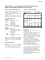 3
3
-
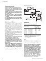 4
4
-
 5
5
-
 6
6
-
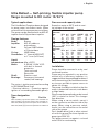 7
7
-
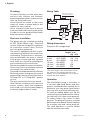 8
8
-
 9
9
-
 10
10
-
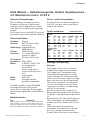 11
11
-
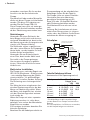 12
12
-
 13
13
-
 14
14
-
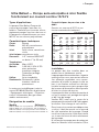 15
15
-
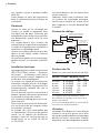 16
16
-
 17
17
-
 18
18
-
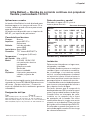 19
19
-
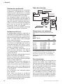 20
20
-
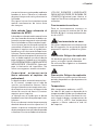 21
21
-
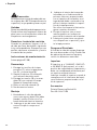 22
22
-
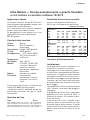 23
23
-
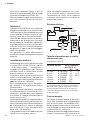 24
24
-
 25
25
-
 26
26
-
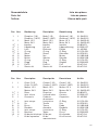 27
27
-
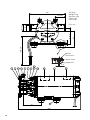 28
28
-
 29
29
-
 30
30
-
 31
31
-
 32
32


SPX FLOW Ultra Ballast Pump Manual de usuario
- Tipo
- Manual de usuario
en otros idiomas
Artículos relacionados
-
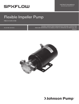 SPX FLOW Bilge, Deck Wash and Refueling pump Manual de usuario
-
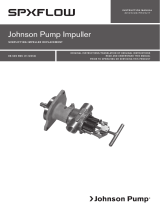 SPX FLOW Original Impeller Kit Manual de usuario
-
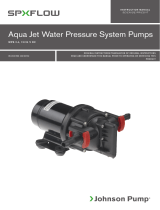 SPX FLOW Aqua jet WPS Manual de usuario
-
 SPX FLOW Macerator Pump Manual de usuario
-
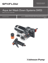 SPX FLOW Aqua Jet WD Pump Manual de usuario
-
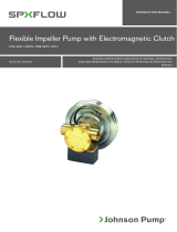 SPX FLOW Heavy Duty Electro-Magnetic Clutch Pump FB-5001 Series Manual de usuario
-
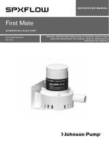 SPX FLOW First Mate Manual de usuario
-
 SPX FLOW Bilge Pump Float Switche Guía del usuario
-
 SPX FLOW Vacuum Switch Manual de usuario
-
 SPX FLOW PUMProtector Inlet Manual de usuario


