Hampton Bay HD28906AGB Guía de instalación
- Tipo
- Guía de instalación

Item #1001 492 705
Model #HD28906
Use and Care Guide
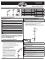
LOW VOLTAGE PATHLIGHT AND FLOODLIGHT KIT
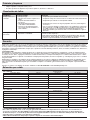
Part Description Quantity
A
Lens cover
2
B
Lens
2
C
20W Halogen MR11 Bulb
2
D
Body
2
E
Adjustment screw
2
F
Post
2
G
Connector
2
H
Spike
2
I
Top Cover
6
J
10W Halogen T3 Bulb
6
K
Bulb socket
6
L
Post
6
M
Connector
6
N
Spike
6
O
120W Transformer
1
P
Wire AWG14 SPT2W 75’
1
Q
Plastic anchors
2
R
Screws
2
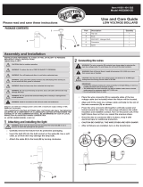
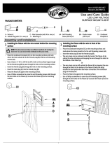
PACKAGE CONTENTS
Assembly and Installation
1
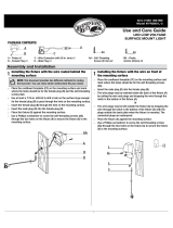
Attaching and installing the oodlight
2
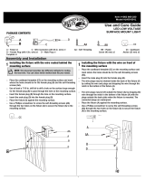
Attaching and installing the pathlight
WARNING: Never push the xture into the ground by the lamp body (D) or use a
hammer to insert the spike (H) into the ground.
WARNING: Never push the xture into the ground by the lens cover (I) or use a
hammer to insert the spike (N) into the ground.
CAUTION: Safe for outdoor operation
WARNING: To reduce the risk of FIRE OR INJURY TO PERSONS:
WARNING: Turn off/unplug and allow to cool before replacing lamp.
WARNING: Lamp gets HOT quickly! Contact only switch/plug when turning on.
Do not touch hot lens, guard or enclosure.
WARNING: Keep the lamp away from materials that may burn.
WARNING: Do not touch the lamp at any time. Use a soft cloth. Oil from skin may
damage the lamp.
WARNING: Do not operate the luminaire tting with a missing or damaged lens
or bulb protector.
□ Carefully remove the xture from its protective packaging.
□ Run the wire through the notch in the top of the spike (H) and attach
the spike to the post (F) by turning clockwise.
□ Loosen the set screw (1) and slide off the light cap (A).
□ Remove the lens cover (B) by turning counterclockwise.
□ Do not remove the lens from the lens cover.
□ Insert the bulb (C) into the bulb socket.
Use a soft cloth, as oil from skin may
damage the lamp bulb.
□ Replace the lens cover (B) and the light cap
(A) over the body (D). Adjust the light’s beam
by sliding the cap back and forth (back = wide
beam, front = narrow beam) and screw the set
screw (1) in place once the proper light beam
is found.
□ Attach the body (D) and the post (F) using the
adjustment screw (E) and rotating clockwise.
□ Adjust the xture’s angle by loosening the
adjustment screw (E) and retightening it.
□ Ensure the lens points up and never towards
the ground.
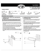
□ Carefully remove the xture from its protective packaging.
□ Pass the wire through the notch in the top of the spike (N) and
attach the spike and post (L) by pressing them together.
□ Insert the bulb (J) into the bulb socket (K). Use a soft cloth, as oil
from skin may damage the lamp bulb.
□ Attach the cover (I) and the post (L) together by turning clockwise.
WARNING: Install in accordance with all local codes and ordinances.
Only for use with low voltage power units with a maximum output rating of 15V,
300W per secondary.
FOR LANDSCAPE LIGHTING SYSTEMS ONLY. OUTDOOR USE ONLY. THE DEVICE IS
ACCEPTED AS A COMPONENT OF A LANDSCAPE LIGHTING SYSTEM WHERE THE
SUITABILITY OF THE COMBINATION SHALL BE DETERMINED BY CSA OR LOCAL
INSPECTION AUTHORITIES HAVING JURISDICTIO
N.
PATHLIGHT UL LISTED UNDER MODEL # U201159
SPOTLIGHT UL LISTED UNDER MODEL # U201167
Please read and save these instructions
INSTRUCTIONS PERTAINING TO A RISK OF FIRE, OR INJURY TO PERSONS
IMPORTANT SAFETY INSTRUCTIONS
Lighted lamp is HOT!
O
P
Q
R
3
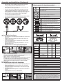
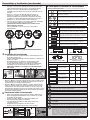
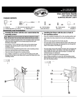
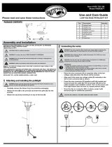
Connecting the wires
WARNING: The wire connector (G) & (M) contacts have sharp edges for piercing
the main low voltage cable. To avoid injury, do not touch the metal contacts.
CAUTION: The wire from the low voltage power unit shall be 12-16 AWG type
underground low Energy Circuit Cable or SPT2W.
IMPORTANT:
• Protect the wiring by routing it in close proximity to the light tting, or next to a
building structure such as a house or deck.
• The landscape wire and connector can also be hidden under stone or buried
under grass at a maximum depth of 6” (15.24 cm).
• Do not submerge xture in water.
WARNING: Risk of Electric Shock. Install all luminaires 10 ft. (3.05 m) or more
from a pool, spa or fountain.
A
B
C
D
F
E
G
H
I
J
K
L
N
M
A
B
1
C
D
F
E
H
G R E
A
S
E
!
I
J
K
L
N
M
IMPORTANT: We recommend to apply petroleum grease (not included) around the
post threading when replacing the head after you change the light bulb. Do not
overtighten the head onto the post.

Assembly and Installation (Continued)
□ Place the wire connector (G) on opposite sides of the low
voltage cable (P) where the xture will be located.
□ Align and t the main low voltage cable (P) vertically to the
slot of wire connector (G) as shown.
□ Press the wire connector (G) together until fully seated and
locked around the cable (P). Pre-set prongs will pierce the
cable insulation and establish contact. Turn on the power unit.
If the light xture does not turn on, repeat previous steps.
□ Once the clip-on connector (G) is in place, wrap it with
electrical tape for additional protection.
□ CAUTION BE CAREFUL! THE WIRE STABS ARE VERY SHARP!
□ After all xtures are installed, turn on the transformer.
□ This transformer is weatherproof and suitable for outdoor and
indoor use.
□ Install the transformer (O) at a level where the controls are
visible and accessible.
□ Do not install behind shrubs. It will affect the dusk-to-dawn
photocell for Auto mode.
□ Photocell will not operate properly if installed too close to a
nighttime light source.
□ MOUNT AT LEAST 12 INCHES (30CM) ABOVE GROUND
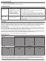
□ Open the front panel and remove the plastic plate by pulling on it.
□ Remove the landscape wire (P) insulation 1/2 in. from both
wires and twist ends.
□
Insert wires under each terminal plate on the transformer (O)
and tighten screws.
□ Gently pull on the landscape wire to verify if the connection is
strong.
□ Verify that there are no loose cable strands.
□ Replace the plastic plate and close the panel.
G
4
Installing the transformer
5
Connecting the cable to the transformer
O
12 in. (12.7 mm)
P
1/2 in. (12.7 mm)
PULL
O
P
6
How to operate the transformer controls
WARNING: To reduce the risk of FIRE OR INJURY TO PERSONS:
WARNING: Do not install within 10 ft. (3 m) of a pool, spa or fountain.
WARNING: There are no serviceable parts inside the power supply unit. DO
NOT DISASSEMBLE.
WARNING: Do not submerge the transformer.
WARNING: Do not connect two or more transformers in parallel.
WARNING: Do not use with a dimmer.
CAUTION: Plug the power supply unit directly into a GFCI outlet that is marked
“wet location”.
The maximum output of this transformer is 120 watts. Do not
overload the transformer. Be sure that the total cumulative wattage of all 12 volt
xtures connected to the transformer is equal to or less than 120 watts. This garden
light system must be installed in accordance with all local codes and ordinances. If
you are experiencing problems, contact a qualied electrician. WARNING: For use
with 12 volt low voltage outdoor landscape lighting system only. Not for use with
submersible light or pool/spa equipment.
WARNING: Do not use an extension cord.
□ SAFE
PHOTOCELL
Mount the transformer
□ Option 1: Standard wall mounting
Insert the two (2) included support screws 3.5” (9 cm) apart in a wall
near an electrical outlet and mount the transformer.
□ Option 2: Brick or cement wall mounting
Drill two (2) holes of 5/16” (8 mm), 3.5” (9 cm) apart from each other,
in a wall near an electrical outlet and place the two (2) plastic
anchors included. Insert the two (2) support screws in the anchors
until they have about 1/4” (6 mm) of space left to mount the
transformer.
Press to conrm a selection.
Press to modify or change a mode. Press it to exit any
settings without saving.
Press these to select and go through the interface.
Press at the same time to change time and date. *Necessary for
Timer, Auto and Sunwise settings to work properly.
Press at the same time to change Sunwise time zone.
*Necessary for optimal Sunwise mode.
/
+
+
ENTER
ENTER
MODE
MODE
MODE
The time at which the lights will turn On. This step comes
after selecting a Mode. (Shows up for Timer Mode only)
The time at which the lights will turn Off. This step comes
after selecting a Mode. (Auto, Timer and Sunwise only)
Select this to close the lights at dawn. When selecting an end
time, scroll using up and down until the icon shows up (Auto
and Sunwise only)
NORTH zone
Refers to locations from north of Chicago, IL.
CENTRAL zone
Refers to locations between Chicago, IL and southern Missouri.
SOUTH zone
Refers to locations south of Missouri.
START
END
NORTH
SOUTH
CENTRAL
Less than 20%: Normal Less than 100%: Normal
Over 120%, shuts down
reduce load
Blinking:
Overloaded over 100%
LOADLOAD
LOADLOAD
Safety mesure of current consumption
Recommended Control Settings
Modes Functionality Outdoor Indoor
Dusk-to
Dawn
Always ON YES YES NO
Always OFF
YES YES NO
Fixed start and end time
YES YES NO
Uses the light sensor
(photocell) to Open/Close
the lights
YES NO YES
Astronomical timer auto-
matically adjusts to local
sunrise/sunset times
YES YES YES
ON
OFF
TIMER
AUTO
SUNWISE
*The channels will only turn on at the exact start time selected for Timer and dusk for Sunwise.

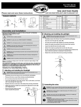
Care and Cleaning
Troubleshooting
Warranty
Cable Selection
□ Clean the xture with a soft, dry cloth.
□ Do not use any cleaners with chemicals, solvents or harsh abrasives.
The xture will not
light
Only some lights
work
• There is no power.
• There is a disconnection or break in
the wire.
• The transformer setting is incorrect.
• There are too many xtures
connected to the transformer.
• The lights are not turning on after
selecting Timer or Sunwise mode.
• The problem here is with the xture’s
connector or light bulb.
• Check that the power is on.
• Check if there is a loose connection at the transformer screw terminal.
• Check that the mode is not set to OFF.
• Check that the load icon is not ashing. If it does, remove some xtures.
• Timer and Sunwise mode only open up at their exact start time setting (Start
for timer and dusk for Sunwise). Ex: if it is 8 PM at your location and you set
the start time to 7 PM, the channel won’t turn on until 7 PM the next day.
• Check the connector to make sure the wire stabs have pierced the landscape
wire.
• To check a light bulb, exchange it with one from a xture that is working
(remember to be careful, as the bulbs can get very hot – also touch bulbs with
a soft cloth only).
Problem Possible cause Solution
WHAT IS COVERED
The manufacturer warrants this lighting xture to be free from defects in materials and workmanship for a period of two (2) years from the date of
purchase. This warranty applies only to the original consumer and only to products used in normal use and service. If this product is found to be
defective, the manufacturer’s only obligation, and your exclusive remedy, is the repair or replacement of the product at the manufacturer’s discretion,
provided that the product has not been damaged through misuse, abuse, accident, modications, alterations, neglect or mishandling.
WHAT IS NOT COVERED
This warranty shall not apply to any product that is found to have been improperly installed, set-up, or used in any way not in accordance with the
instructions supplied with the product. This warranty shall not apply to a failure of the product as a result of an accident, misuse, abuse, negligence,
alteration or faulty installation, or any other failure not relating to faulty material or workmanship. This warranty shall not apply to the nish on any
portion of the product, such as surface and/or weathering, as this is considered normal wear and tear.
The manufacturer does not warrant and specially disclaims any warranty, whether express or implied, of tness for a particular purpose, other than
the warranty contained herein. The manufacturer specically disclaims any liability and shall not be liable for any consequential or incidental loss or
damage, including but not limited to any labor / expense costs involved in the replacement or repair of said product.
Contact the Customer Service Team at 1-855-HD-HAMPTON or visit www.hamptonbay.com.
Total Fixture Wattage
0-60 Watts
61-120 Watts
121-180 Watts
181-240 Watts
241-300 Watts
600W Transformer = (2X300) Watts
900W Transformer = (3X300) Watts
51-100 feet
Cable Length
101-150 feet
16 AWG 16 AWG 14 AWG
16 AWG 14 AWG 12 AWG
14 AWG 12 AWG NOT RECOMMENDED
14 AWG 12 AWG NOT RECOMMENDED
12 AWG NOT RECOMMENDED NOT RECOMMENDED
12 AWG NOT RECOMMENDED NOT RECOMMENDED
12 AWG NOT RECOMMENDED NOT RECOMMENDED
0-50 feet
12 VOLT TAP
Total Fixture Wattage
0-60 Watts
61-120 Watts
121-180 Watts
181-240 Watts
241-300 Watts
600W Transformer = (2X300) Watts
900W Transformer = (3X300) Watts
51-100 feet
Cable Length
101-150 feet
16 AWG* 16 AWG 16 AWG
16 AWG* 16 AWG 12 AWG
14 AWG* 14 AWG 12 AWG
14 AWG* 14 AWG 12 AWG
12 AWG* 12 AWG NOT RECOMMENDED
12 AWG* 12 AWG NOT RECOMMENDED
12 AWG* 12 AWG NOT RECOMMENDED
0-50 feet
15 VOLT TAP
This data is provided as a general guideline. Actual performance will depend on the installation layout, the xtures, and the
condition of the cable. NOTE: Most LED landscape lighting xtures can operate with full illumination from 9V down to as little as
6V. It is possible to have extended length runs with LED xtures that go beyond the specications shown in the guidelines above.
Additional landscape lighting cable can be purchased at your local Home Depot store.
* NOT RECOMMENDED FOR HALOGEN LANDSCAPE LIGHTS

Núm. de artículo 1001 492 705
Núm. de modelo HD28906
Guía de uso y cuidado
JUEGO DE LUZ DE PASILLO DE BAJO VOLTAJE Y REFLECTOR
Pieza Descripción Cantidad
A
Cubierta de los lentes
2
B
Lentes
2
C
Bombilla MR11 de halógeno
de 20 vatios
2
D
Cuerpo
2
E
Tornillo de ajuste
2
F
Poste
2
G
Conector
2
H
Estaca
2
CONTENIDO DEL PAQUETE
Ensamblaje y Instalación
1
Adjuntar y la instalación de los reector
2
Adjuntar y la instalación de la luz
ADVERTENCIA: Nunca empuje el accesorio en el suelo por el cuerpo de la lámpara
(D) o utilizar un martillo para insertar la estaca (H) en el suelo.
ADVERTENCIA: No introduzca el aparato en el suelo por la cubierta superior (I) o usar
un martillo para insertar la estaca (N) en el suelo.
□ Con cuidado, retire el dispositivo de su empaque protector.
□ Tienda el cable a través de la ranura en la parte superior de
la estaca (H) e instale la estaca en el poste (F) girando hacia la
derecha.
□ Aoje el tornillo prisionero (1) y deslice hacia afuera la tapa de la
lámpara (A).
□ Extraiga la cubierta de los lentes (B) girándola hacia la izquierda.
□ No retire los lentes de la cubierta de los lentes.
□ Inserte la bombilla (C) en el receptáculo de
la bombilla. Use un paño suave ya que el aceite
de la piel puede dañar la bombilla de la lámpara.
□ Vuelva a colocar la cubierta de los lentes (B)
sobre el cuerpo (D). Ajuste el rayo de luz
deslizando la tapa de un lado al otro
(atrás = rayo ancho, frente = rayo angosto)
e inserte el tornillo prisionero (en su lugar
una vez se encuentre el rayo de luz apropiado.
□ Coloque el cuerpo (D) y el posterior (F) con el
tornillo de ajuste (E) y girando en sentido horario.
□ Ajustar el ángulo del aparato aojando el
tornillo de ajuste (E) y volver a apretar la misma.
□ Asegúrese de que lentes deben apunten hacia
arriba y nunca hacia el suelo.
□ Con cuidado, retire el dispositivo de su empaque protector.
□ Pase el cable a través de la ranura en la parte superior de la estaca
(N) e instale la estaca y el poste (L) presionándolos juntos.
□ Inserte la bombilla (J) en el receptáculo de la bombilla (K). Use un
paño suave ya que el aceite de la piel puede dañar
la bombilla de la lámpara.
□ Instale la cubierta (I) y el poste (L) juntos girando hacia
la derecha.
Únicamente para uso con unidades de energía de bajo voltaje con una capacidad
nominal de salida máxima de 15V, 300W por secundario.
PARA SISTEMAS DE ILUMINACIÓN DE PAISAJE ÚNICAMENTE. PARA USO EN
EXTERIORES ÚNICAMENTE. EL DISPOSITIVO ES ACEPTADO COMO UN
COMPONENTE DE UN SISTEMA DE ILUMINACIÓN DE PAISAJE DONDE LA
IDONEIDAD DE LA COMBINACIÓN SERÁ DETERMINADA POR CSA O
AUTORIDADES DE INSPECCIÓN LOCALES CON JURISDICCIÓN.
LUZ LISTADO UL CONFORME A MODELO No. U201159
REFLECTOR LISTADO UL CONFORME A MODELO No. U201167
Por favor, lea y guarde estas instrucciones.
INSTRUCCIONES CONCERNIENTES A RIESGO DE INCENDIO, O LESIONES A LAS
PERSONAS INSTRUCCIONES DE SEGURIDAD IMPORTANTES
¡La lámpara encendida se pone CALIENTE!
O
P
Q
R
3
Conexión de los cables
A
B
C
D
F
E
G
H
I
J
K
L
N
M
A
B
1
C
D
F
E
H
G R E
A
S
E
!
I
J
K
L
N
M
IMPORTANTE: Se recomienda aplicar grasa de petróleo (no incluido) alrededor del
poste roscado al reemplazar la cabeza después de cambiar la bombilla. No apriete
demasiado la cabeza en el poste.
I
Cubierta superior
6
J
Bombilla T3 de halógeno de 10 vatios
6
K
Receptáculo de la bombilla
6
L
Poste
6
M
Conector
6
N
Estaca
6
O
Transformador de 120 vatios
1
P
Cable AWG14 SPT2W 75 pies
1
Q
Anclas de plástico
2
R
Tornillos
2
PRECAUCIÓN: Segura para funcionamiento en exteriores.
ADVERTENCIA: Para reducir el riesgo de INCENDIO O LESIONES PERSONALES:
ADVERTENCIA: Apague / desconecte y deje que se enfríe antes de reemplazar
la lámpara.
ADVERTENCIA: !Las lámparas se CALIENTAN rápidamente! Solamente ponga en
contacto el interruptor/enchufe cuando la encienda.
ADVERTENCIA: Mantenga la lámpara lejos de materiales que se puedan quemar.
ADVERTENCIA: No toque la lámpara en ningún momento. Use un paño suave. El
aceite de la piel puede dañar la lámpara.
ADVERTENCIA: No opere el accesorio de la luminaria si no tiene o tiene dañados
los lentes o el protector de la bombilla.
ADVERTENCIA: Instale de acuerdo con todos los códigos y ordenanzas locales.
PRECAUCIÓN: El cable de la unidad de energía de baja tensión será de 12 a 16
AWG tipo subterránea de baja energía Circuito de cable o SPT2W.
ADVERTENCIA: Los conector de cable (G) y (M) contactos tienen bordes alados
para perforar el cable principal de baja tensión. Para evitar lesiones, no toque
los contactos metálicos.
ADVERTENCIA: Riesgo de choque eléctrico. Instale todas las luminarias 10 pies
(3.05 m) o más de un estanque, manantial o fuente.
IMPORTANTE:
• Proteger el cableado de enrutamiento en las proximidades de la luminaria, o al
lado de una estructura de edicio, como una casa o de la cubierta.
• El cable de jardín y conector también se pueden ocultar bajo piedras o
enterrados bajo la hierba a una profundidad máxima de 6 “ (15,24 cm).
• No sumerja aparato en agua.

Ensamblaje y Instalación (continuado)
□ Coloque el conector del cable (G) en los lados opuestos del
cable de baja tensión (P) en la que se encuentra el aparato.
□ Alinear y colocar el cable de baja tensión principal (P)
verticalmente en la ranura del conector de cable (G) como se
muestra.
□ Presione el conector del cable (G) juntos hasta que se
asiente por completo y cerrado alrededor del cable (P).
Puntas preestablecidos perforarán el aislamiento del cable
y establecer contacto. Encienda la unidad de potencia. Si la
lámpara no se enciende, repita los pasos anteriores.
□ Una vez esté en su lugar el conector tipo pinza (G), envuélvalo
con cinta aislante para protección adicional.
□ ¡PRECAUCIÓN, TENGA CUIDADO! ¡LAS CUCHILLAS DEL
CABLE SON MUY FILOSAS!
□ Una vez instalados todos los accesorios, encienda el
transformador.
□ Este transformador es impermeable y conveniente para el uso
al aire libre y bajo techo.
□ Instale el transformador (O) en un nivel donde los controles son
visible y accesible.
□ No instale detrás de los arbustos. Afectará la fotocélula
anochecer hasta el amanecer en el modo automático.
□ La fotocélula no funcionará correctamente si está instalado
demasiado cerca de una fuente de luz durante la noche.
□ MONTAJE AL MENOS 12 PULGADAS (30 CM) POR ENCIMA
DEL SUELO
□ Abra el panel frontal y retire la placa de plástico tirando de él.
□ Retire 1/2 pulgada del aislamiento de los 2 cables en el cable
de jardín y gire las puntas.
□ Inserte los cables debajo de cada placa terminal en el
transformador (O) y apriete los tornillos.
□ Tire suavemente del cable de jardín para vericar si la
conexión es fuerte.
□ Compruebe que no haya hilos de cable sueltos.
□ Vuelva a colocar la placa de plástico y cierre el panel.
G
4
Instalación del transformador
5
Conexión del cable al transformador
desde 12 pulg.
a 48 pulg.
(30 a 75 cm)
O
12 in. (12.7 mm)
P
1/2 in. (12.7 mm)
HALAR
O
P
6
Cómo operar los controles de transformadores
ADVERTENCIA: Para reducir el riesgo de INCENDIO O LESIONES
PERSONALES:
ADVERTENCIA: Riesgo de choque eléctrico. Instale todas las luminarias 10 pies
(3.05 m) o más de un estanque, manantial o fuente.
ADVERTENCIA: No sumerja el transformador.
ADVERTENCIA: No lo use con un dimmer.
ADVERTENCIA: No utilice un cable de extensión.
Monte el transformador
□ Opción 1: Montaje en pared estándar. Inserte los dos tornillos (2) de
apoyo incluidos 3,5” (9 cm) de distancia en una pared cerca de un
enchufe eléctrico y montar el transformador.
□ Opción 2: Montaje en pared de ladrillo o cemento. Taladre dos (2)
agujeros de 5/16” (8 mm), 3,5” (9 cm) de distancia el uno del otro,
en una pared cerca de un enchufe eléctrico y coloque los dos (2)
plasticanchors incluidos. Inserte los dos tornillos (2) de apoyo en los
anclajes hasta que tienen alrededor de 1/4” (6 mm) de espacio dejó
de montar el transformador.
ADVERTENCIA: No hay piezas que pueda reparar la fuente de alimentación.
NO DESARME.
PRECAUCIÓN:
Conecte la fuente de alimentación directamente a una toma GFCI
que está marcado “lugar húmedo”.
La salida máxima de este transformador es
de 120 vatios. No sobrecargue el transformador. Asegúrese de que la potencia total
acumulada de todos los accesorios de 12 voltios conectada al transformador es igual o
inferior a 120 vatios.
Este sistema de luz del jardín debe ser instalado de acuerdo con
todos los códigos y ordenanzas locales. Si usted está experimentando problemas,
póngase en contacto con un electricista calicado.
ADVERTENCIA
Para el uso con
12 voltios de bajo voltaje único sistema de iluminación del paisaje al aire libre. No
debe utilizarse con la luz sumergible o equipo de la piscina / spa.
ADVERTENCIA: No conecte dos o más transformadores en paralelo.
Pulse para conrmar la selección.
Pulse para modicar o cambiar un modo. Púlselo para salir de la
conguración sin guardar.
Pulse estos botones para seleccionar y pasar por la interfaz.
Presione al mismo tiempo para cambiar el tiempo y la fecha. * Necesario para
el “Timer”, “Auto” y la conguración “Sunwise” funcione correctamente.
Presione al mismo tiempo para cambiar la zona horaria “Sunwise”.
* Necesario para el modo “Sunwise” óptima.
/
+
+
ENTER
ENTER
MODE
MODE
MODE
El momento en que las luces se encenderán. Este paso se produce después
de la selección de un modo. (Muestra para modo de “Timer” solamente)
El momento en que las luces se apagarán. Este paso se produce después
de la selección de un modo. (“Auto, Timer y Sunwise” solamente)
Seleccione esta opción para cerrar las luces en la madrugada. Al
seleccionar una hora de nalización, desplácese usando arriba y
abajo hasta que el icono aparece (“Auto y Sunwise” solamente)
Zona NORTH
Se reere a las poblaciones de al norte de Chicago, IL.
Zona CENTRAL
Se reere a los lugares entre Chicago, IL y el sur de Missouri.
Zona SOUTH
Se reere a los lugares al sur de Missouri.
START
END
NORTH
SOUTH
CENTRAL
Ajustes de control recomendados
Modes Funcionalidad
Al aire libre
Interior
El atardecer
hasta el amanecer
Siempre prendido SÍ SÍ NO
Siempre apagado
SÍ SÍ NO
Inicio y hora de
nalización ja
SÍ SÍ NO
Utiliza el sensor de luz
(fotocélula) para abrir /
cerrar las luces
SÍ NO SÍ
Temporizador astronómico se ajusta
automáticamente a los tiempos
locales de Salida /Puesta de sol
SÍ SÍ SÍ
ON
OFF
TIMER
AUTO
SUNWISE
Menos de 20%: Normal Menos de 100%: Normal
Mas de 120%, se apaga
reducir la carga
Intermitente:
sobrecargado más de 100%
LOADLOAD
LOADLOAD
Medida de seguridad de consumo de corriente
□ SEGURO
CÉLULA
FOTOELÉCTRICA
*Para los modos con minuteros, las luces se encienden sólo al principio (inicio) de su ciclo
(minutero y al atardecer para Sunwise).

Cuidado y limpieza
Resolución de fallas
Garantía
Selección por cable
□ Limpie el aparato con un paño suave y seco.
□ No utilice productos de limpieza con productos químicos, disolventes o abrasivos.
LO QUE ESTÁ CUBIERTO
El fabricante garantiza que este accesorio de iluminación está libre de defectos en materiales y mano de obra durante un período de dos (2) años a
partir de la fecha de compra. Esta garantía se aplica sólo al consumidor original y únicamente a los productos utilizados en condiciones normales
de uso y servicio. Si este producto se encuentre defectuoso, la única obligación del fabricante, y el recurso exclusivo, es la reparación o sustitución
del producto, a discreción del fabricante, siempre que el producto no ha sido dañado por mal uso, abuso, accidentes, modicaciones, alteraciones ,
negligencia o mal manejo.
LO QUE NO CUBRE
Esta garantía no será aplicable a cualquier producto que se demuestre que ha sido mal instalados, conguración, o usado de cualquier manera
no conforme con las instrucciones suministradas con el producto. Esta garantía no se aplicará a una falla del producto como consecuencia de un
accidente, mal uso, abuso, negligencia, alteración o instalación defectuosa, o cualquier otra falla que no se reeran a material defectuoso o mano
de obra. Esta garantía no se aplicará a el acabado de cualquier parte del producto, tal como la supercie y / o intemperie, ya que esto se considera
desgaste normal.
El fabricante no garantiza y especialmente niega cualquier garantía, ya sea expresa o implícita, de aptitud para un propósito en particular, que no
sea la garantía contenida en el presente documento. El fabricante declina cada responsabilidad y no será responsable por cualquier pérdida o
daño consecuente o incidental, incluyendo pero no limitado a cualquier coste laboral / gastos involucrados en el reemplazo o reparación de dicho
producto.
Póngase en contacto con el Equipo de Servicio al Cliente al 1-855-HD-HAMPTON o visite www.hamptonbay.com.
Total Fixture Vatiaje
0-60 Watts
61-120 Watts
121-180 Watts
181-240 Watts
241-300 Watts
Transformador 600W = (2x300) Watts
Transformador 900W = (3x300) Watts
51-100 pies
Longitud del cable
101-150 pies
16 AWG 16 AWG 14 AWG
16 AWG 14 AWG 12 AWG
14 AWG 12 AWG NO RECOMENDADO
14 AWG 12 AWG NO RECOMENDADO
12 AWG NO RECOMENDADO NO RECOMENDADO
12 AWG NO RECOMENDADO NO RECOMENDADO
12 AWG NO RECOMENDADO NO RECOMENDADO
0-50 pies
TAP 12 VOLTIOS
Total Fixture Vatiaje
0-60 Watts
61-120 Watts
121-180 Watts
181-240 Watts
241-300 Watts
Transformador 600W = (2x300) Watts
Transformador 900W = (3x300) Watts
51-100 pies
Longitud del cable
101-150 pies
16 AWG* 16 AWG 16 AWG
16 AWG* 16 AWG 12 AWG
14 AWG* 14 AWG 12 AWG
14 AWG* 14 AWG 12 AWG
12 AWG* 12 AWG NO RECOMENDADO
12 AWG* 12 AWG NO RECOMENDADO
12 AWG* 12 AWG NO RECOMENDADO
0-50 pies
TAP 15 VOLTIOS
Estos datos se proporcionan como una guía general. El rendimiento real dependerá de la disposición de la instalación, los
accesorios y el estado del cable. NOTA: La mayor parte del paisaje LED luminarias pueden funcionar con plena iluminación
de 9V hasta tan poco como 6V. Es posible tener una longitud extendida se ejecuta con luminarias LED que van más allá de las
especicaciones contenidas en las directrices anteriores.
Cable adicional iluminación del paisaje se puede comprar en su tienda local de Home Depot.
* NO RECOMENDADO PARA LUCES HALÓGENAS PAISAJE
El dispositivo no se
enciende
Solo algunas luces
funcionan.
• No hay energia
• Hay una desconexión o ruptura en el
cable.
• El ajuste del transformador es
incorrecta.
• Hay demasiados dispositivos
conectados al transformador.
• Las luces no prenden después de
seleccionar el modo de minutero o
modo Sunwise.
• El problema es con el conector del
dispositivo o la bombilla.
• Compruebe que la unidad está encendida.
• Compruebe si hay una conexión suelta en el terminal de tornillo transformador.
•
Compruebe que el modo no está ajustado en OFF.
• Compruebe que el icono de carga no parpadea. Si lo hace, retirar algunos
accesorios.
•
Sólo en el modo de minutero y Sunwise abren a su conguración en la hora de
inicio exacta. Ej: si es 8 PM en su ubicación y se establece la hora de inicio de
las 7 PM, el canal no se encenderá hasta las 7 PM del día siguiente. Es lo
mismo para Sunwise, pero la hora de inicio es la hora del atardecer segun su
ubicación.
• Revise el conector para asegurarse de que las cuchillas del cable hayan per
forado el cable de paisaje.
• Para probar una bombilla, intercámbiela con una del dispositivo que esté
funcionando. Tenga cuidado, ya que las bombillas se pueden poner muy
calientes. Toque las bombillas con un paño suave únicamente.
Problema Causa posible Solución
-
 1
1
-
 2
2
-
 3
3
-
 4
4
-
 5
5
-
 6
6


Hampton Bay HD28906AGB Guía de instalación
- Tipo
- Guía de instalación
en otros idiomas
Artículos relacionados
-
 Hampton Bay HD28601SD Guía de instalación
-
 Hampton Bay HD28905BK Guía de instalación
-
 Hampton Bay HD38609BK Guía de instalación
-
 Hampton Bay IYR2601L-2 Instrucciones de operación
-
 Hampton Bay JAO1691L Instrucciones de operación
-
 Hampton Bay JAO2601LM-2 Instrucciones de operación
-
 Hampton Bay HD38684BK Guía de instalación
-
 Hampton Bay JAO2601LL Instrucciones de operación
-
 Hampton Bay JAO2601L Instrucciones de operación
-
 Hampton Bay HD33677BK Guía de instalación


Otros documentos
-
GE HEAVY DUTY OUTDOOR DIGITAL STAKE TIMER Manual de usuario
-
Defiant DW9519GY-A(2) Instrucciones de operación
-
Deckorators 12 Volt 12 Watt DC Transformer Guía de instalación
-
Unbranded DW10237AZ8-C Instrucciones de operación
-
-
Progress Lighting P8518-31 Guía de instalación
-
 Malibu 8302-9200-01 Instrucciones de operación
-
Progress Lighting P5299-31 Instrucciones de operación
-
-
