Deckorators 12 Volt 50 Watt DC Transformer Guía de instalación
- Tipo
- Guía de instalación

equal
power to the enre
the aached cap.
Pre - Installation Notes
Follow all naonal and local building/electrical codes.
Transformer must be plugged into a GFCI outlet.
Transformer can support up to 50 was output.
Don’t cut any wires. Extra wire length can be coiled up.
Do not use extension cords.
Do not use within 10 feet of ponds, pools, or spas.
If using insulated wire staples to hold the wires in
place, be sure not to pierce or crush the wires.
Keep away from external heat sources.
Step 1
Mount the Transformer and Photocell
1.1 Use (4) stainless steel screws (not included) to
mount the transformer a minimum of 12” above
the ground level and within reach of a 120V AC
GFCI outlet. The 120V AC power cord aached to
the transformer is 5 feet long. The transformer
can be mounted under the deck but the control
panel on the transformer should be accessible to
change sengs.
1.2 Plug the transformer into the GFCI outlet.
1.3 Use a stainless steel screw (not included) to
mount the photocell in a locaon that can sense
dusk and dawn (night and day) condions. The
aached photocell cord is 5 feet long.
onnector (optional but
recommended)
clos
ed loop connector. The closed loop connector
on each e
nd and is 6” long. The closed loop connector is
used to connect the Main Wiring back in
to the transformer. This reduces the voltage
in the system.
se a 2 output splier on the last ligh
t fixture of the run. Plug the last light fixture into one of the 2 outputs spliers
Plug an extension har
ness into the other male connecon of the 2 output splier. Run enough
end to end to rea
ch back to the Tee Connector of the transformer. Use the closed loop connector
to make the connecon between the
extension harness and the Tee Connector.
12 Volt 50 Watt DC Smart Transformer
INST#: XIS50WHS-REV 11-17
Step 3
Install the Lights and Finalize Installation
3.1 Connect the rest of the Main Wiring Connecons (not included) per their instrucons on reverse side of page.
3.2 Connect the desired light fixtures (not included) per their individual instrucons.
3.3 Refer to the included Control instrucons for operaon of the transformer. The Control instrucons should be retained
for future reference.
Conector en T
Transformador
Célula
fotoeléctrica
2 Salida
Disidente
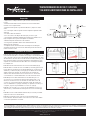
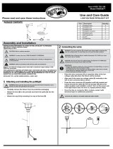
Paso 1: Utilice (4) tornillos de acero inoxidable (no incluidos) para
montar el transformador a un mínimo de 12 pulg por encima del nivel del
suelo y al alcance de un tomacorriente GFCI de 120 VCA (fig. 1). El cable
de alimentación de 120 V CA conectado al transformador mide 5 pies de
largo. El transformador se puede montar debajo de la plataforma, pero
el panel de control del transformador debe ser accesible para cambiar
la configuración.
Paso 2: Enchufe el transformador en el tomacorriente GFCI (fig. 2).
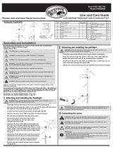
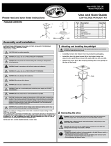
Paso 3: Utilice un tornillo de acero inoxidable (no incluido) para montar
la fotocélula en una ubicación que pueda detectar las condiciones del
atardecer y el amanecer (día y noche) (fig. 3). El cable de la fotocélula
adjunto mide 5 pies de largo. No instale el fotosensor detrás de
arbustos. Esto afectará al fotosensor. El fotosensor no funcionará
correctamente si se instala demasiado cerca de una fuente de luz.
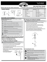
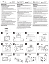
Paso 4: Ejecute el cable de alimentación de salida de 4 pies con
el conector en T conectado a la ubicación de la primera luz o una
ubicación central si las luces se ubicarán en varias direcciones. El
conector en T se puede asegurar sin apretar usando (2) tornillos de
acero inoxidable # 4 x 1 pulg (no incluidos). No apriete los tornillos por
completo, ya que esto puede dañar el conector en T (fig. 4).
Paso 5: Si es necesario, los 3 conectores de salida del conector en T
están activos y suministrarán la misma potencia a todo el sistema (fig.
5).
Paso 6: Conecte el cable hembra del kit de luz (no incluido) e instálelo
según las instrucciones del kit de luz.
Paso 7: Consulte las instrucciones de control incluidas para el
funcionamiento del transformador. Las instrucciones de control deben
conservarse para futuras consultas.
Instrucciones de instalación
equal
power to the enre
the aached cap.
Pre - Installation Notes
Follow all naonal and local building/electrical codes.
Transformer must be plugged into a GFCI outlet.
Transformer can support up to 50 was output.
Don’t cut any wires. Extra wire length can be coiled up.
Do not use extension cords.
Do not use within 10 feet of ponds, pools, or spas.
If using insulated wire staples to hold the wires in
place, be sure not to pierce or crush the wires.
Keep away from external heat sources.
Step 1
Mount the Transformer and Photocell
1.1 Use (4) stainless steel screws (not included) to
mount the transformer a minimum of 12” above
the ground level and within reach of a 120V AC
GFCI outlet. The 120V AC power cord aached to
the transformer is 5 feet long. The transformer
can be mounted under the deck but the control
panel on the transformer should be accessible to
change sengs.
1.2 Plug the transformer into the GFCI outlet.
1.3 Use a stainless steel screw (not included) to
mount the photocell in a locaon that can sense
dusk and dawn (night and day) condions. The
aached photocell cord is 5 feet long.
onnector (optional but
recommended)
clos
ed loop connector. The closed loop connector
on each e
nd and is 6” long. The closed loop connector is
used to connect the Main Wiring back in
to the transformer. This reduces the voltage
in the system.
se a 2 output splier on the last ligh
t fixture of the run. Plug the last light fixture into one of the 2 outputs spliers
Plug an extension har
ness into the other male connecon of the 2 output splier. Run enough
end to end to rea
ch back to the Tee Connector of the transformer. Use the closed loop connector
to make the connecon between the
extension harness and the Tee Connector.
12 Volt 50 Watt DC Smart Transformer
INST#: XIS50WHS-REV 11-17
Step 3
Install the Lights and Finalize Installation
3.1 Connect the rest of the Main Wiring Connecons (not included) per their instrucons on reverse side of page.
3.2 Connect the desired light fixtures (not included) per their individual instrucons.
3.3 Refer to the included Control instrucons for operaon of the transformer. The Control instrucons should be retained
for future reference.
Conector en T
Transformador
Célula
fotoeléctrica
2 Salida
Disidente
Preparación
• Siga todos los códigos eléctricos y de construcción nacionales y
locales.
• El transformador debe estar enchufado a un tomacorriente GFCI
marcado como "lugar húmedo".
• El transformador puede soportar hasta 50 vatios. (125) luces de 0,4
vatios.
• No corte ningún cable. Se puede enrollar cualquier longitud de cable
adicional.
• No utilice cables de extensión.
• No lo use a menos de 10 pies de estanques, piscinas o spas.
• Si usa grapas de alambre aisladas para mantener los alambres en su
lugar, asegúrese de no perforar ni aplastar los alambres.
• Mantener alejado de fuentes de calor externas.
• No hay piezas reparables dentro de la unidad de fuente de
alimentación. No desarmar.
• Configure el modo de transformador en Siempre encendido para
asegurarse de que las luces funcionen durante la prueba. Consulte las
instrucciones de control.
fig. 1 fig. 2
LOS DIAGRAMAS Y LAS INSTRUCCIONES DE ESTE FOLLETO SON SÓLO PARA FINES ILUSTRATIVOS Y NO TIENEN SU PROPÓSITO PARA REEMPLAZAR A UN PROFESIONAL CON LICENCIA. CUALQUIER CONSTRUCCIÓN O USO DEL PRODUCTO DEBE SEGUIR TODOS
LOS CÓDIGOS DE ZONIFICACIÓN Y / O CONSTRUCCIÓN LOCALES. EL CONSUMIDOR ASUME TODOS LOS RIESGOS Y RESPONSABILIDAD ASOCIADOS CON LA CONSTRUCCIÓN O EL USO DE ESTE PRODUCTO. EL CONSUMIDOR O CONTRATISTA DEBE TOMAR
TODAS LAS MEDIDAS NECESARIAS PARA GARANTIZAR LA SEGURIDAD DE TODOS LOS INVOLUCRADOS EN EL PROYECTO, INCLUYENDO, PERO NO LIMITADO A USAR EL EQUIPO DE SEGURIDAD APROPIADO. EXCEPTO LO CONTENIDO EN LA GARANTÍA LIMITADA
ESCRITA, EL GARANTE NO OFRECE NINGUNA OTRA GARANTÍA, YA SEA EXPRESA O IMPLÍCITA, Y NO SERÁ RESPONSABLE DE NINGÚN DAÑO, INCLUYENDO DAÑOS CONSECUENTES.
©2021 UFP Retail Solutions, LLC. Deckorators es una marca registrada de UFP Industries, Inc. en los EE. UU. Todos los derechos reservados.
68956 U.S. Highway 131, White Pigeon, MI 49099
13865 12/21
www.deckorators.com
equal
power to the enre
the aached cap.
Pre - Installation Notes
Follow all naonal and local building/electrical codes.
Transformer must be plugged into a GFCI outlet.
Transformer can support up to 50 was output.
Don’t cut any wires. Extra wire length can be coiled up.
Do not use extension cords.
Do not use within 10 feet of ponds, pools, or spas.
If using insulated wire staples to hold the wires in
place, be sure not to pierce or crush the wires.
Keep away from external heat sources.
Step 1
Mount the Transformer and Photocell
1.1 Use (4) stainless steel screws (not included) to
mount the transformer a minimum of 12” above
the ground level and within reach of a 120V AC
GFCI outlet. The 120V AC power cord aached to
the transformer is 5 feet long. The transformer
can be mounted under the deck but the control
panel on the transformer should be accessible to
change sengs.
1.2 Plug the transformer into the GFCI outlet.
1.3 Use a stainless steel screw (not included) to
mount the photocell in a locaon that can sense
dusk and dawn (night and day) condions. The
aached photocell cord is 5 feet long.
onnector (optional but
recommended)
clos
ed loop connector. The closed loop connector
on each e
nd and is 6” long. The closed loop connector is
used to connect the Main Wiring back in
to the transformer. This reduces the voltage
in the system.
se a 2 output splier on the last ligh
t fixture of the run. Plug the last light fixture into one of the 2 outputs spliers
Plug an extension har
ness into the other male connecon of the 2 output splier. Run enough
end to end to rea
ch back to the Tee Connector of the transformer. Use the closed loop connector
to make the connecon between the
extension harness and the Tee Connector.
12 Volt 50 Watt DC Smart Transformer
INST#: XIS50WHS-REV 11-17
Step 3
Install the Lights and Finalize Installation
3.1 Connect the rest of the Main Wiring Connecons (not included) per their instrucons on reverse side of page.
3.2 Connect the desired light fixtures (not included) per their individual instrucons.
3.3 Refer to the included Control instrucons for operaon of the transformer. The Control instrucons should be retained
for future reference.
Conector en T
Transformador
Célula
fotoeléctrica
2 Salida
Disidente
fig. 4
fig. 5
fig. 3
TRANSFORMADOR DE DC DE 12 VOLTIOS
Y 50 VATIOS INSTRUCCIONES DE INSTALACIÓN
-
 1
1

Deckorators 12 Volt 50 Watt DC Transformer Guía de instalación
- Tipo
- Guía de instalación
en otros idiomas
Artículos relacionados
Otros documentos
-
 Hampton Bay HD28906AGB Guía de instalación
-
 Kichler Lighting Showscape 12217 Manual de usuario
-
Progress Lighting P8518-31 Guía de instalación
-
 Hampton Bay HD28905BK Guía de instalación
-
 Hampton Bay HD33679BK Manual de usuario
-
 Hampton Bay HD33677BK Guía de instalación
-
Portfolio 8201080378 Guía de instalación
-
 Hampton Bay HD33678BK Guía de instalación
-
 PRO-DF AL66005 Guía de instalación
-
Brinkmann COACH El manual del propietario


