La página se está cargando...

Pre - Installation Notes
Follow all naonal and local building and electrical
codes.
Transformer must be plugged into a GFCI outlet.
Transformer can support up to 12 was.
Do not cut any wires. Any extra wire length can be
coiled up.
Do not use extension cords.
Do not use within 10 feet of ponds, pools, or spas.
Cover the photocell sensor with dark tape to make
the lights work while tesng.
If using insulated wire staples to hold the wires in
place, be sure not to pierce or crush the wires.
Step 1
Prepare the Transformer
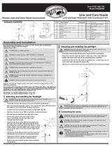
1.1 Properly align the photocell plug with the transformer
receptacle and firmly push the plug into place.
1.2 Tighten the plasc nut by turning clockwise. If the
photocell is already aached, check to make sure
plasc nut is completely ght for a weatherproof seal.
Step 2
Mount the Transformer and Photocell
2.1 Use (4) #4 x ½“ screws (not supplied) to mount
transformer to an exterior wall surface or deck face a
minimum of 12” above ground level. Plug the
transformer into the GFCI outlet.
2.2 Mount the round photocell holder next to the
transformer with the supplied screw. Ensure the
locaon of the photocell can sense dusk and dawn.
2.3 Peel off the protecve film covering the adhesive on
the top surface of the round photocell holder. Align
the photocell and press firmly onto the adhesive.
2.4 To test the power supply during installaon,
temporarily cover the photocell sensor with dark
tape so the lights will come on during installaon.
Be sure to remove the tape for normal operaon.
(Locaon of Photocell Sensor shown in picture 2.3.)
Step 3
Plug in Tee Connector
3.1 Run the 9’ power cable from the photocell to the
locaon of the first light fixture. If needed, the
power cable can fit through a 1/2” hole.
3.2 Plug the output connector from the photocell into
the supplied T-Connector. Press firmly unl the
connecon is fully engaged.
3.3 Connecon is fully engaged when there is minimal
gap between the output and Tee connectors.
3.4 Connect light fixtures per their instrucons.
3.5 Any unused Tee Connector terminals or spliers in
the system must be sealed using the aached cap.
12 Volt 12 Watt DC Transformer
INST#: XIS12WL-REV 1-15
Transformador
Célula fotoeléctrica
Conector en T
Mínimo 12 pulg por encima del suelo
Célula
fotoeléctrica
Sensor
Producción
Conector
9 pies de
potencia
Cable
Pre - Installation Notes
Follow all naonal and local building and electrical
codes.
Transformer must be plugged into a GFCI outlet.
Transformer can support up to 12 was.
Do not cut any wires. Any extra wire length can be
coiled up.
Do not use extension cords.
Do not use within 10 feet of ponds, pools, or spas.
Cover the photocell sensor with dark tape to make
the lights work while tesng.
If using insulated wire staples to hold the wires in
place, be sure not to pierce or crush the wires.
Step 1
Prepare the Transformer
1.1 Properly align the photocell plug with the transformer
receptacle and firmly push the plug into place.
1.2 Tighten the plasc nut by turning clockwise. If the
photocell is already aached, check to make sure
plasc nut is completely ght for a weatherproof seal.
Step 2
Mount the Transformer and Photocell
2.1 Use (4) #4 x ½“ screws (not supplied) to mount
transformer to an exterior wall surface or deck face a
minimum of 12” above ground level. Plug the
transformer into the GFCI outlet.
2.2 Mount the round photocell holder next to the
transformer with the supplied screw. Ensure the
locaon of the photocell can sense dusk and dawn.
2.3 Peel off the protecve film covering the adhesive on
the top surface of the round photocell holder. Align
the photocell and press firmly onto the adhesive.
2.4 To test the power supply during installaon,
temporarily cover the photocell sensor with dark
tape so the lights will come on during installaon.
Be sure to remove the tape for normal operaon.
(Locaon of Photocell Sensor shown in picture 2.3.)
Step 3
Plug in Tee Connector
3.1 Run the 9’ power cable from the photocell to the
locaon of the first light fixture. If needed, the
power cable can fit through a 1/2” hole.
3.2 Plug the output connector from the photocell into
the supplied T-Connector. Press firmly unl the
connecon is fully engaged.
3.3 Connecon is fully engaged when there is minimal
gap between the output and Tee connectors.
3.4 Connect light fixtures per their instrucons.
3.5 Any unused Tee Connector terminals or spliers in
the system must be sealed using the aached cap.
12 Volt 12 Watt DC Transformer
INST#: XIS12WL-REV 1-15
Transformador
Célula fotoeléctrica
Conector en T
Mínimo 12 pulg por encima del suelo
Célula
fotoeléctrica
Sensor
Producción
Conector
9 pies de
potencia
Cable
TRANSFORMADOR DE DC DE 12 VOLTIOS
Y 12 VATIOS INSTRUCCIONES DE INSTALACIÓN
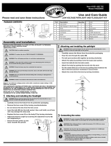
Paso 1: Alinee correctamente el enchufe de la fotocélula con el receptáculo
del transformador y empuje firmemente el enchufe en su lugar (fig. 1).
Paso 2: Apriete la tuerca de plástico girándola en el sentido de las agujas
del reloj (fig. 2). Si la fotocélula ya está colocada, verifique que la tuerca
de plástico esté completamente apretada para un sello resistente a la
intemperie.
Paso 3: Use (4) tornillos # 4 x 1⁄2 pulg (no incluidos) para montar el
transformador en una superficie de pared exterior o en la superficie de
la plataforma a un mínimo de 12 pulg sobre el nivel del suelo. Enchufe el
transformador en el tomacorriente GFCI (figs. 3 y 4).
Paso 4: Monte el soporte de fotocélula redondo junto al transformador con
el tornillo suministrado (fig. 5). Asegúrese de que la ubicación de la fotocélula
pueda detectar el anochecer y el amanecer. No instale el fotosensor detrás
de arbustos. Esto afectará al fotosensor. El fotosensor no funcionará
correctamente si se instala demasiado cerca de una fuente de luz.
Paso 5: Despegue la película protectora que cubre el adhesivo en la
superficie superior del soporte de la fotocélula redonda. Alinear la fotocélula
y presionar firmemente sobre el adhesivo (fig. 6).
Paso 6: Para probar la fuente de alimentación durante la instalación, cubra
temporalmente el sensor de la fotocélula con cinta oscura para que las luces
se enciendan durante la instalación. Asegúrese de quitar la cinta para un
funcionamiento normal. (La ubicación del sensor de fotocélula se muestra en
la fig. 6.)
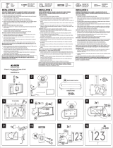
Paso 7: Ejecute el cable de alimentación de 9 pies desde la fotocélula hasta
la ubicación del primer artefacto de iluminación. Si es necesario, el cable de
alimentación puede pasar por un orificio de 1/2 pulg (fig. 7).
Paso 8: Enchufe el conector de salida de la fotocélula en el conector
en T suministrado. Presione firmemente hasta que la conexión esté
completamente acoplada (fig. 8).
Paso 9: La conexión está completamente acoplada cuando hay un espacio
mínimo entre la salida y los conectores en T (fig. 9).
Paso 10: Conecte los artefactos de iluminación según sus instrucciones.
Paso 11: Cualquier terminal o divisor del conector en T que no se utilice en
el sistema debe sellarse con la tapa adjunta (fig. 10).
Instrucciones de instalación
Pre - Installation Notes
Follow all naonal and local building and electrical
codes.
Transformer must be plugged into a GFCI outlet.
Transformer can support up to 12 was.
Do not cut any wires. Any extra wire length can be
coiled up.
Do not use extension cords.
Do not use within 10 feet of ponds, pools, or spas.
Cover the photocell sensor with dark tape to make
the lights work while tesng.
If using insulated wire staples to hold the wires in
place, be sure not to pierce or crush the wires.
Step 1
Prepare the Transformer
1.1 Properly align the photocell plug with the transformer
receptacle and firmly push the plug into place.
1.2 Tighten the plasc nut by turning clockwise. If the
photocell is already aached, check to make sure
plasc nut is completely ght for a weatherproof seal.
Step 2
Mount the Transformer and Photocell
2.1 Use (4) #4 x ½“ screws (not supplied) to mount
transformer to an exterior wall surface or deck face a
minimum of 12” above ground level. Plug the
transformer into the GFCI outlet.
2.2 Mount the round photocell holder next to the
transformer with the supplied screw. Ensure the
locaon of the photocell can sense dusk and dawn.
2.3 Peel off the protecve film covering the adhesive on
the top surface of the round photocell holder. Align
the photocell and press firmly onto the adhesive.
2.4 To test the power supply during installaon,
temporarily cover the photocell sensor with dark
tape so the lights will come on during installaon.
Be sure to remove the tape for normal operaon.
(Locaon of Photocell Sensor shown in picture 2.3.)
Step 3
Plug in Tee Connector
3.1 Run the 9’ power cable from the photocell to the
locaon of the first light fixture. If needed, the
power cable can fit through a 1/2” hole.
3.2 Plug the output connector from the photocell into
the supplied T-Connector. Press firmly unl the
connecon is fully engaged.
3.3 Connecon is fully engaged when there is minimal
gap between the output and Tee connectors.
3.4 Connect light fixtures per their instrucons.
3.5 Any unused Tee Connector terminals or spliers in
the system must be sealed using the aached cap.
12 Volt 12 Watt DC Transformer
INST#: XIS12WL-REV 1-15
Transformador
Célula fotoeléctrica
Conector en T
Mínimo 12 pulg por encima del suelo
Célula
fotoeléctrica
Sensor
Producción
Conector
9 pies de
potencia
Cable
Preparación
• Siga todos los códigos eléctricos y de construcción nacionales y locales.
• El transformador debe estar enchufado a un tomacorriente GFCI marcado
como "lugar húmedo".
• El transformador puede soportar hasta 12 vatios. (30) luces de 0,4 vatios.
• No corte ningún cable. Se puede enrollar cualquier longitud de cable
adicional.
• No utilice cables de extensión.
• No lo use a menos de 10 pies de estanques, piscinas o spas.
• Cubra el sensor de la fotocélula con cinta oscura para que las luces
funcionen durante la prueba.
• Si usa grapas de alambre aisladas para mantener los alambres en su lugar,
asegúrese de no perforar ni aplastar los alambres.
• No hay piezas reparables dentro de la unidad de fuente de alimentación. No
desarmar.
fig. 1 fig. 2
LOS DIAGRAMAS Y LAS INSTRUCCIONES DE ESTE FOLLETO SON SÓLO PARA FINES ILUSTRATIVOS Y NO TIENEN SU PROPÓSITO PARA REEMPLAZAR A UN PROFESIONAL CON LICENCIA. CUALQUIER CONSTRUCCIÓN O USO DEL PRODUCTO DEBE SEGUIR TODOS
LOS CÓDIGOS DE ZONIFICACIÓN Y / O CONSTRUCCIÓN LOCALES. EL CONSUMIDOR ASUME TODOS LOS RIESGOS Y RESPONSABILIDAD ASOCIADOS CON LA CONSTRUCCIÓN O EL USO DE ESTE PRODUCTO. EL CONSUMIDOR O CONTRATISTA DEBE TOMAR
TODAS LAS MEDIDAS NECESARIAS PARA GARANTIZAR LA SEGURIDAD DE TODOS LOS INVOLUCRADOS EN EL PROYECTO, INCLUYENDO, PERO NO LIMITADO A USAR EL EQUIPO DE SEGURIDAD APROPIADO. EXCEPTO LO CONTENIDO EN LA GARANTÍA LIMITADA
ESCRITA, EL GARANTE NO OFRECE NINGUNA OTRA GARANTÍA, YA SEA EXPRESA O IMPLÍCITA, Y NO SERÁ RESPONSABLE DE NINGÚN DAÑO, INCLUYENDO DAÑOS CONSECUENTES.
©2021 UFP Retail Solutions, LLC. Deckorators es una marca registrada de UFP Industries, Inc. en los EE. UU. Todos los derechos reservados.
68956 U.S. Highway 131, White Pigeon, MI 49099
13865 12/21
www.deckorators.com
Pre - Installation Notes
Follow all naonal and local building and electrical
codes.
Transformer must be plugged into a GFCI outlet.
Transformer can support up to 12 was.
Do not cut any wires. Any extra wire length can be
coiled up.
Do not use extension cords.
Do not use within 10 feet of ponds, pools, or spas.
Cover the photocell sensor with dark tape to make
the lights work while tesng.
If using insulated wire staples to hold the wires in
place, be sure not to pierce or crush the wires.
Step 1
Prepare the Transformer
1.1 Properly align the photocell plug with the transformer
receptacle and firmly push the plug into place.
1.2 Tighten the plasc nut by turning clockwise. If the
photocell is already aached, check to make sure
plasc nut is completely ght for a weatherproof seal.
Step 2
Mount the Transformer and Photocell
2.1 Use (4) #4 x ½“ screws (not supplied) to mount
transformer to an exterior wall surface or deck face a
minimum of 12” above ground level. Plug the
transformer into the GFCI outlet.
2.2 Mount the round photocell holder next to the
transformer with the supplied screw. Ensure the
locaon of the photocell can sense dusk and dawn.
2.3 Peel off the protecve film covering the adhesive on
the top surface of the round photocell holder. Align
the photocell and press firmly onto the adhesive.
2.4 To test the power supply during installaon,
temporarily cover the photocell sensor with dark
tape so the lights will come on during installaon.
Be sure to remove the tape for normal operaon.
(Locaon of Photocell Sensor shown in picture 2.3.)
Step 3
Plug in Tee Connector
3.1 Run the 9’ power cable from the photocell to the
locaon of the first light fixture. If needed, the
power cable can fit through a 1/2” hole.
3.2 Plug the output connector from the photocell into
the supplied T-Connector. Press firmly unl the
connecon is fully engaged.
3.3 Connecon is fully engaged when there is minimal
gap between the output and Tee connectors.
3.4 Connect light fixtures per their instrucons.
3.5 Any unused Tee Connector terminals or spliers in
the system must be sealed using the aached cap.
12 Volt 12 Watt DC Transformer
INST#: XIS12WL-REV 1-15
Transformador
Célula fotoeléctrica
Conector en T
Mínimo 12 pulg por encima del suelo
Célula
fotoeléctrica
Sensor
Producción
Conector
9 pies de
potencia
Cable
fig. 9 fig. 10fig. 9 fig. 10
fig. 4
fig. 5 fig. 6
fig. 7 fig. 8
fig. 3
1/1