Hampton Bay JAO2601LL Instrucciones de operación
- Tipo
- Instrucciones de operación

1
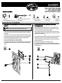
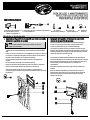
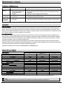
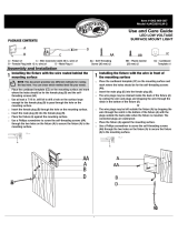
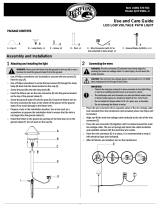
PACKAGE CONTENTS
A – Fixture x1 C – Wire Connector (with 36 in. wire) x1 AA – Self-Threading BB – Plastic Anchor CC – Cardboard
B – Female Plug (with 12 in. wire) x1 D – Male Plug x1 Screw (30 mm) x2 (25 mm) x2 Template x1
1
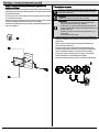
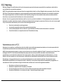
Installing the fixture with the wire routed behind the mounting
surface
1
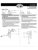
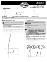
Installing the fixture with the wire in front of the
mounting surface
NOTE: This document provides two different methods for routing the
lead wire. You can chose which method best fits your needs.
□ Place the cardboard template (CC) on the mounting surface and mark
where the holes should be for the female plug (B) and the self-threading
screws (AA).
□ Use at least a 7/16 in. drill bit to drill a hole on the surface large enough
for the female plug (B) to pass through the hole on the mounting surface.
□ Insert the female plug (B) through the hole on the mounting surface.
□ Insert the male plug (D) into the female plug (B).
□ Place the fixture (A) against the mounting surface.
□ Use a Phillips screwdriver to screw the self-threading screws (AA) through
the two holes on the fixture (A) to secure the fixture (A) to the mounting
surface.
□ Place the cardboard template (CC) on the mounting surface and
mark where the holes should be for the self-threading screws (AA).
□ Insert the male plug (D) into the female plug (B).
□ The wire plugs may be retained inside the back of the fixture (A) by
coiling the wire and plugs and dropping the wire through the notch in
the bottom of the fixture (A).
Or
□ The wire plugs may be left outside the fixture (A) by dropping the wire
through the notch in the bottom of the fixture (A) with the plugs
outside the back plate when the fixture is mounted. The connected
plugs are waterproof.
□ Place the fixture (A) against the mounting surface.
□ Use a Phillips screwdriver to screw the self-threading screws (AA)
through the two holes on the fixture (A) to secure the fixture (A) to the
mounting surface.

2
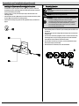
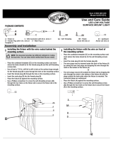
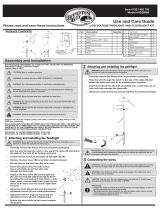
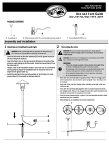
Installing the fixture on a surface using plastic anchors
2
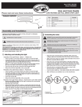
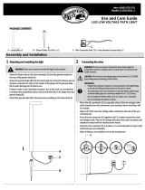
Connecting the wires
□ If installation requires the plastic anchors (BB), then place the cardboard
template (CC) on the mounting surface and mark where the holes should be
for the self-threading screws (AA).
□ At those marks, use a 15/64 drill bit (or 6 mm) to drill two holes in the
mounting surface.
□ Push the plastic anchors (BB) into the two holes until the heads of the plastic
anchors (BB) are flush with the mounting surface.
□ Continue the assembly using either of the applicable Step 1 procedures on
page 1.
WARNING: The wire connector (C) contacts have sharp edges for
piercing the main low voltage cable. To avoid injury, do not touch the
metal contacts.
CAUTION: The wire from the low voltage power unit should be 12-16
AWG type underground low Energy Circuit Cable.
IMPORTANT:
□ Protect the wiring by routing it in close proximity to the light fitting,
or next to a building structure such as a house or a deck.
□ The landscape wire and connector can also be hidden under stone
or buried under grass at a maximum depth of 6 in. (15.24 cm).
□ Do not install the fixture within 10 ft. of a pool, spa, or fountain.
□ Do not submerge the fixture in water.
□ Place the wire connector (C) on opposite sides of the low voltage cable
(not included) from the transformer (not included) where the fixture will
be located.
□ Align and fit the main low voltage cable vertically to the slot of the wire
connector (C).
□ Press the wire connector (C) together until it is locked around the main
low voltage cable. The pre-set prongs will pierce the cable insulation
and establish contact with the electrical wire inside.
□ Once the wire connector (C) is in place, it is recommended to wrap it
with electrical tape (not included).
□ After all fixtures are installed, turn on the transformer.

3
□ Clean the fixture with a soft dry cloth.
□ Do not use any cleaners with chemicals, solvents or harsh abrasives.
WHAT IS COVERED
The manufacturer warrants this lighting fixture to be free from defects in materials and workmanship for a period of five (5) years from date of purchase. This warranty
applies only to the original consumer and only to products used in normal use and service. If this product is found to be defective, the manufacturer’s only obligation,
and your exclusive remedy, is the repair or replacement of the product at the manufacturer’s discretion, provided that the product has not been damaged through
misuse, abuse, accident, modifications, alterations, neglect or mishandling.
WHAT IS NOT COVERED
This warranty shall not apply to any product that is found to have been improperly installed, set-up, or used in any way not in accordance with the instructions supplied
with the product. This warranty shall not apply to a failure of the product as a result of an accident, misuse, abuse, negligence, alteration, or faulty installation, or any
other failure not relating to faulty material or workmanship. This warranty shall not apply to the finish on any portion of the product, such as surface and/or weathering,
as this is considered normal wear and tear.
The manufacturer does not warrant and specifically disclaims any warranty, whether express or implied, of fitness for a particular purpose, other than the warranty
contained herein. The manufacturer specifically disclaims any liability and shall not be liable for any consequential or incidental loss or damage, including but not
limited to any labor / expense costs involved in the replacement or repair of said product.
Contact the Customer Service Team at 1-855-HD-HAMPTON or visit HAMPTONBAY.COM.
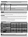
12 VOLT TAP
Cable Length
Total Fixture Wattage
0-50 feet
51-100 feet
101-150 feet
0-60 Watts
16 AWG
16 AWG
14 AWG
61-120 Watts
16 AWG
14 AWG
12 AWG
121-180 Watts
14 AWG
12 AWG
Not Recommended
181-240 Watts
14 AWG
12 AWG
Not Recommended
241-300 Watts
12 AWG
Not Recommended
Not Recommended
600W Transformer = (2x300) Watts
12 AWG
Not Recommended
Not Recommended
900W Transformer = (3x300) Watts
12 AWG
Not Recommended
Not Recommended
15 VOLT TAP
Cable Length
Total Fixture Wattage
0-50 feet
51-100 feet
101-150 feet
0-60 Watts
16 AWG*
16 AWG
16 AWG
61-120 Watts
16 AWG*
16 AWG
12 AWG
121-180 Watts
14 AWG*
14 AWG
12 AWG
181-240 Watts
14 AWG*
14 AWG
12 AWG
241-300 Watts
12 AWG*
12 AWG
Not Recommended
600W Transformer = (2x300) Watts
12 AWG*
12 AWG
Not Recommended
900W Transformer = (3x300) Watts
12 AWG*
12 AWG
Not Recommended
* NOT RECOMMENDED FOR HALOGEN LANDSCAPE LIGHTS
This data is provided as a general guideline. Actual performance will depend on the installation layout, the fixtures, and the condition of the cable.
NOTE: Most LED landscape lighting fixtures can operate with full illumination from 9V down to as little as 6V. It is possible to have extended length
runs with LED fixtures that go beyond the specifications shown in the guidelines above.
Problem
Possible Cause
Solution
The fixture will not
light.
□ There is no power.
□ There is a disconnection or
break in the wire.
□ The transformer setting is
incorrect.
□ Check the outlet and ensure that a breaker or GFCI circuit has not been tripped.
□ Follow the wires from the fixture and ensure a continuous connected path back to the transformer.
□ Check the settings on the transformer.
The light flickers
(one fixture).
□ There is a loose wire
connector to the fixture.
□ Tighten the wire connector and ensure the metal contacts pierce the insulation on the low voltage
cable from the transformer.
The lights flicker
(all fixtures).
□ There is a loose connection at
the transformer.
□ Unplug the transformer from the outlet and visually inspect the positive and negative connecting
points. Each wire should be securely screwed in and not in contact with any other.

4
CONTENIDO DEL PAQUETE
A –Dispositivo de Iluminación x1 C –Conector Cable (con un cable de 36 pulgadas) x1 AA– Tornillos BB – Anclas de CC – Plantilla de
B –Enchufe Hembra (con un D – Enchufe Macho x1 Autorroscantes (30mm) x2 Plastico (25mm) x2 Cartón x1
cable de 12 pulgadas) x1
1
Instalando el dispositivo de iluminación con el cable enrutado
detrás de la superficie de montaje
1
Instalando el dispositivo de iluminación con el cable
delante de la superficie de montaje
NOTA: Este documento proporciona dos métodos diferentes para
enrutar el cable conductor. Puede elegir el método que mejor se
adapte a sus necesidades.
□ Coloque la plantilla de cartón (CC) en la superficie de montaje y marque los
orificios para el enchufe hembra (B) y para los tornillos de autorroscantes
(AA).
□ Utilice por lo menos una broca de 7/16 pulgadas para perforar un orificio en
la superficie lo suficientemente grande como para que el enchufe hembra
(B) pase a través del orificio en la superficie de montaje.
□ Inserte el enchufe hembra (B) a través del orificio en la superficie de
montaje.
□ Inserte el enchufe macho (D) en el enchufe hembra (B).
□ Coloque el dispositivo de iluminación (A) contra la superficie de montaje.
□ Utilice un destornillador Phillips para atornillar los tornillos de
autorroscantes (AA) a través de los dos orificios en el dispositivo de
iluminación (A) para asegurar el dispositivo de iluminación (A) al soporte de
la superficie.
□ Coloque la plantilla de cartón (CC) en la superficie de montaje y
marque los orificios para los tornillos de autorroscantes (AA).
□ Inserte el enchufe macho (D) en el enchufe hembra (B).
□ Los enchufes de alambre pueden ser retenidos dentro de la parte
posterior del dispositivo de iluminación (A) enrollando el alambre y los
enchufes y dejando caer el alambre a través de la muesca en la parte
inferior del dispositivo de iluminación (A).
O
□ Los enchufes de alambre pueden quedar fuera del dispositivo de
iluminación (A) dejando caer el cable a través de la muesca en el fondo
del dispositivo de iluminación (A) con los enchufes fuera de la placa
trasera cuando se monte el dispositivo. Los enchufes son
impermeables.
□ Coloque el dispositivo de iluminación (A) contra la superficie de
montaje.
□ Utilice un destornillador Phillips para atornillar los tornillos de
autorroscantes (AA) a través de los dos orificios del dispositivo de
iluminación (A) para fijar el dispositivo de iluminación (A) a la
superficie de montaje.

5
Instale el dispositivo de iluminación en una superficie con
anclajes de plástico
2
Conexión de los cables
□ Si la instalación requiere de anclajes de plástico (BB), coloque la plantilla de
cartón (CC) en la superficie de montaje y marque los orificios para los tornillos
de autorroscantes (AA).
□ En esas marcas, use una broca de 15/64 (o 6 mm) para perforar dos orificios
en la superficie de montaje.
□ Empuje los anclajes de plástico (BB) en los dos orificios hasta que los anclajes
de plástico (BB) estén alineados con la superficie de montaje.
□ Continúe el ensamblaje utilizando uno de los procedimientos aplicables del
Paso 1 en la página 1.
ADVERTENCIA: Los contactos del cable conector (C) tienen bordes filosos
para atravesar el cable principal de bajo voltaje. No toque los contactos
de metal para evitar lesiones.
PRECAUCIÓN: El cable de la unidad de bajo voltaje debe ser un cable
subterráneo de circuito de baja corriente tipo 12-16 AWG.
I IMPORTANTE:
□ Proteja el cableado colocándolo bien cerca del portalámparas, o
siguiendo la estructura de una casa o plataforma.
□ El cable externo y el conector pueden quedar escondidos bajo una
piedra o enterrados bajo el césped a una profundidad máxima de of 6
pulgadas (15.24 cm).
□ No instale el accesorio a menos de 10 pies de una alberca, spa, o
fuente de agua.
□ No sumergir el accesorio en agua.
□ Coloque el cable conector (C) en el lado opuesto al del cable de bajo
voltaje (no incluido) del transformador (no incluido) donde el accesorio
será ubicado.
□ Alinee y ajuste el cable principal de bajo voltaje verticalmente al
espacio del cable conector (C).
□ Presione el cable conector (C) hasta que este asegurado al cable
principal de bajo voltaje. Las clavijas atravesarán el aislamiento del
cable y establecerán contacto con el cable eléctrico de adentro.
□ Una vez que el cable conector (C) esté en su lugar, se recomienda
aislarlo cubriéndolo con cinta aisladora (no incluida).
□ Después de instalar todos los accesorios, encienda el transformador.

6
□ Limpia la lámpara con un paño suave y seco.
□ No uses limpiadores con químicos, solvents, o productos abrasivos.
Problema
Causa Posible
Solución
El accesorio no
enciende.
□ No hay corriente.
□ El cable está desconectado o roto.
□ El transformador está mal
configurado.
□ Verifique el tomacorriente y asegúrese que no esté apagado el interruptor o circuito GFC.
□ Siga los cables desde el accesorio y asegúrese que esté en buen estado bien conectado al
transformador.
□ Verifique que esté bien la configuración del transformador.
La luz parpadea
(en un accesorio).
□ Hay algún cable conector suelto
en el accesorio.
□ Ajuste el cable conector y asegúrese que los contactos metálicos atraviesan el aislamiento en
el cable de bajo voltaje desde el transformador.
Las luzes
parpadea (todos
los accesorios).
□ Hay una conexión suelta en el
transformador.
□ Desenchufe el transformador del tomacorriente e inspeccione visualmente los puntos de
conexión positivo y negativo. Cada cable debe estar bien atornillado y sin tocar a los demás.
LO QUE ESTA CUBIERTO
El fabricante garantiza que esta lámpara no presentará defectos materiales o de fabricación por un período de cinco (5) años a partir de la fecha de compra. Esta
garantía es válida sólo para el comprador original y sólo cubre los productos en uso y funciones normales. Si se descubre algún defecto en este producto, la única
obligación y solución exclusiva del fabricante, a criterio del mismo, será reparar o reemplazar el producto siempre y cuando el defecto no sea resultado de un mal uso,
abuso, accidente, modificaciones, alteraciones,negligencia o manejo indebido.
LO QUE (NO) ESTA CUBIERTO
Esta garantía no cubre ningún producto instalado, configurado o usado incorrectamente sin seguir las instrucciones adjuntas al producto. Esta garantía no cubre
fallas del producto a consecuencia de un accidente, mal uso, abuso, negligencia, modificaciones o instalaciones defectuosas, o cualquier otra falla no relacionada
con defectos materiales o de fabricación. Esta garantía no se aplica al acabado de ninguna parte del producto, como por ejemplo el de la superficie, ni al deterioro
por condiciones ambientales, ya que eso se considera un desgaste normal.
El fabricante no garantiza y rechaza especialmente cualquier garantía, expresa o implícita, de idoneidad para un propósito en particular, distinta de la garantía
indicada aquí. El fabricante se exime específicamente de cualquier obligación y no es responsable por daños o pérdidas directas o indirectas, lo que incluye cualquier
costo de mano de obra o gastos relacionados con el reemplazo o reparación de dicho producto.
Comunícate con el Equipo de Servicio al Cliente al 1-855-HD-HAMPTON o visita HAMPTONBAY.COM.
GRIFO 12 VOLTIOS
Longitud del Cable
Total Fixture Potencia
0-50 pies
51-100 pies
101-150 pies
0-60 Watts
16 AWG
16 AWG
14 AWG
61-120 Watts
16 AWG
14 AWG
12 AWG
121-180 Watts
14 AWG
12 AWG
No Recomendado
181-240 Watts
14 AWG
12 AWG
No Recomendado
241-300 Watts
12 AWG
No Recomendado
No Recomendado
600W transformador = (2x300) Watts
12 AWG
No Recomendado
No Recomendado
900W transformador = (3x300) Watts
12 AWG
No Recomendado
No Recomendado
GRIFO 15 VOLTIOS
Longitud del Cable
Total Fixture Potencia
0-50 pies
51-100 pies
101-150 pies
0-60 Watts
16 AWG*
16 AWG
16 AWG
61-120 Watts
16 AWG*
16 AWG
12 AWG
121-180 Watts
14 AWG*
14 AWG
12 AWG
181-240 Watts
14 AWG*
14 AWG
12 AWG
241-300 Watts
12 AWG*
12 AWG
No Recomendado
600W transformador = (2x300) Watts
12 AWG*
12 AWG
No Recomendado
900W transformador = (3x300) Watts
12 AWG*
12 AWG
No Recomendado
* NO RECOMENDABLE PARA LUCES EXTERIORES DE HALOGEN
Estos datos se proveen como una guía general. El rendimiento concreto dependerá del diseño de instalación, los accesorios, y la condición de los cables.
NOTA: La mayoría de los accesorios de iluminación LED de exterior pueden funcionar a plena iluminación usando 9V y hasta incluso 6V. Es posible
conseguir largos más extensos con accesorios LED que van más allá de las especificaciones mostradas en la guía de arriba.

7
Warning: Changes or modifications to this unit not expressly approved by the party responsible for compliance could void the
user’s authority to operate the equipment.
NOTE: This equipment has been tested and found to comply with the limits for a Class B digital device, pursuant to Part 15 of the
FCC Rules. These limits are designed to provide reasonable protection against harmful interference in a residential installation.
This equipment generates, uses and can radiate radio frequency energy and, if not installed and used in accordance with the
instructions, may cause harmful interference to radio communications.
However, there is no guarantee that interference will not occur in a particular installation. If this equipment does cause harmful
interference to radio or television reception, which can be determined by turning the equipment off and on, the user is encouraged
to try to correct the interference by one or more of the following measures:
Reorient or relocate the receiving antenna.
Increase the separation between the equipment and receiver.
Connect the equipment into an outlet on a circuit different from that to which the receiver is connected.
Consult the dealer or an experienced radio/TV technician for help.
Advertencia: los cambios o modificaciones de esta unidad que no estén expresamente aprobados por la parte responsable del
cumplimiento pueden anular la autoridad del usuario para operar el equipo.
NOTA: Este equipo ha sido probado y cumple con los límites para un dispositivo digital de Clase B, de acuerdo con la Parte 15 de
las Reglas de la FCC. Estos límites están diseñados para proporcionar una protección razonable contra interferencias
perjudiciales en una instalación residencial. Este equipo genera, utiliza y puede emitir energía de radiofrecuencia y, si no se
instala y utiliza de acuerdo con las instrucciones, puede provocar interferencias perjudiciales a las comunicaciones de radio.
Sin embargo, no hay garantía de que no se produzcan interferencias en una instalación particular. Si este equipo causa
interferencias perjudiciales en la recepción de radio o televisión, lo cual puede comprobarse encendiéndolo y apagándolo, se
recomienda al usuario que intente corregir la interferencia mediante una o más de las siguientes medidas:
Reorientar o reubicar la antena receptora.
Aumente la separación entre el equipo y el receptor.
Conecte el equipo a una toma de un circuito distinto de aquel al que está conectado el receptor.
Consulte al distribuidor o a un técnico de radio / televisión para obtener ayuda.
-
 1
1
-
 2
2
-
 3
3
-
 4
4
-
 5
5
-
 6
6
-
 7
7


Hampton Bay JAO2601LL Instrucciones de operación
- Tipo
- Instrucciones de operación
en otros idiomas
Artículos relacionados
-
 Hampton Bay JAO1691L Instrucciones de operación
-
 Hampton Bay JAO2601LM-2 Instrucciones de operación
-
 Hampton Bay IYR2601L-2 Instrucciones de operación
-
 Hampton Bay HD28906AGB Guía de instalación
-
 Hampton Bay HD38684BK Guía de instalación
-
 Hampton Bay JEF1501L-3 Instrucciones de operación
-
 Hampton Bay JPZ1502L-8PK Instrucciones de operación
-
 Hampton Bay JPV1501L-2/ORB Instrucciones de operación
-
 Hampton Bay JAO1501L-2-6PK Instrucciones de operación


