
11.10
IND1-01
225
INSTALLATION AND MAINTENANCE INSTRUCTIONS
INSTRUCCIONES DE INSTALACIÓN Y MANTENIMIENTO
USA
The user should retain these instructions for future reference • El usuario debe retener estas instrucciones para future referencia
This product must be installed in strict accordance with local plumbing codes.
Product should be installed by a licensed plumber.
Este producto debe ser instalado en estricta conformidad con códigos locales de plomería.
El producto debe ser instalado por un plomero licenciado.
IMPORTANT
DO NOT RETURN ANY MERCHANDISE TO THE VENDOR
NO REGRESE NINGUNA MERCANCIA AL VENDEDOR
For Customer Service, Returns or Technical Questions, please call Sanio’s technical support toll-free at
800-571-8191 (USA) or 800-363-5874 (CDN).
Para servicio de atención al cliente, devoluciones o preguntas técnicas, llamar por favor a la linea gratuita
de apoyo técnico al 800-571-8191 (USA) o el 800-363-5874 (CDN).
notice SANI3.indd 1 30/11/10 10:32:33

,
VERTICAL DISTANCE
(DISTANCIA VERTICAL)
feet (pies)
15
12
9
6
3
0
50 60 70 80 90 100 110 120
15 20 25 30
l/min
US gallon/min
FLOW RATE (FLUJO)
5
6
2
7
7a
3
G
G
H
A
x 1
B
x 5
F
x 1
G
x 2
32 x 55
D
x 1
20 x 32
C
x 1
H
x 4
Ø / 28 (PVC)
Ø 1” / 32 (PVC)
Ø / 22 (CPVC)
B
B
C
D
C
A
7c
25 x 40
90 x 110
SANI 3
®
E
x 1
E’
x 1
1” 1/2
2”
1” 1/2
1” 1/2
K
x 3
50 X 70
J
x 2
2”
I
x 1
CERRADO
CLOSED
K
E''
K
J
B
E’
K
7b
PAGE 2
Sinon - 8071 N-225.qxp 19/04/10 12:15 Page 2
1
3
/4”
3
/4”
L
x 1
14”
M
x 1
1 1/2”
E”
x 1
2”
2”
2'' (50 mm)
30
15
12
9
6
3
60
120
180
240
270
300
feet (pies)
feet (pies)
See section 2.1
K M
N
J
J K M
1
SANILUX
®
1
7
1
03.10
IND1
430
7d
1
2
3
4 4
5
SP
G
H
6
3
5
l/min
m
Ø 32
564
212204
185
294
SANILUXE
268
184
236
358
N
A
D
D
I
1
4
3
2
1
E
D
A
E
D
A
2
4
3
2
1
E
D
A
E
D
A
3
I
D
D
N A
A
B
F
2
A
x 1
G
x 2
H
x 4
J
x 2
K
x 2
L
x 2
M
x 2
B
32 x 55
x 3
C
3,6 x 370
x 1
D
20 x 35
x 2
E
x 3
I
x 1
F
90 x 110
x 1
N
x 1
7a
1
2
F
F
C
C
7C
L MKJ
FERMÉ
CLOSED
ZU
CHIUSO
VASTDRAAIEN
CERRADO
FECHADO
STÄNGD
LUKKET
STENGT
KIINNI
ZAMKNIĘTE
RÖGZÍTETT
ZAMKNOUT
ÎNCHIS
クローズ
7b
2
D
B
B
E
L
L
,
VERTICAL DISTANCE
(DISTANCIA VERTICAL)
feet (pies)
15
12
9
6
3
0
50 60 70 80 90 100 110 120
15 20 25 30
l/min
US gallon/min
FLOW RATE (FLUJO)
5
6
2
7
7a
3
G
G
H
A
x 1
B
x 5
F
x 1
G
x 2
32 x 55
D
x 1
20 x 32
C
x 1
H
x 4
Ø / 28 (PVC)
Ø 1” / 32 (PVC)
Ø / 22 (CPVC)
B
B
C
D
C
A
7c
25 x 40
90 x 110
SANI 3
®
E
x 1
E’
x 1
1” 1/2
2”
1” 1/2
1” 1/2
K
x 3
50 X 70
J
x 2
2”
I
x 1
CERRADO
CLOSED
K
E''
K
J
B
E’
K
7b
PAGE 2
Sinon - 8071 N-225.qxp 19/04/10 12:15 Page 2
1
3
/4”
3
/4”
L
x 1
14”
M
x 1
1 1/2”
E”
x 1
2”
2”
2'' (50 mm)
30
15
12
9
6
3
60
120
180
240
270
300
feet (pies)
feet (pies)
notice SANI3.indd 2 30/11/10 10:32:39

21d
21c
21a
21e
3
38
39
35
15
17
30b
31
30b
32
37
1
12
11
20b
8
7c
61
4
62
2b
30b
30b 30b
31
30b
2a
24
75
18
14
49a
13
10a
9
50b
52
5664
48
28c
65
50a
16
40b
36
34
20
28a
37
30b
31b
30a
30a
31
8
A
G
14
C
B
D
E
F
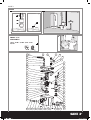
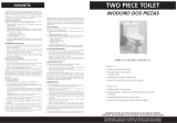
SANI 3
®
SFA SANIFLO
120 V - 60 Hz - 1/2 HP - 4,5 A - IP44 -
6,4 KG
SANI 3
®
PAGE 3
Sinon - 8071 N-225.qxp 19/04/10 12:15 Page 3
P130
Ø 3/4” or 1”
15 feet
58
7e
7c
E
B
B
I
37
notice SANI3.indd 3 30/11/10 10:32:43

1
INTRODUCTION
This macerator is manufactured in a factory which is quality cer-
tified to ISO 9001 (2000) accredited by AFAQ.This
equipment benefits from the latest technological innovations
concerning soundproofing.To benefit fully from the advantages
provided by this new generation of appliances, it is important
to comply with the installation instructions.
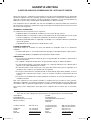
1.1 - GENERAL DESCRIPTION
The macerating unit is a residential pumping system for
toilet and bathroom fixtures. The system is comprised of three
major components :
- the macerating unit, which connects to the outlet of
a rear spigot outlet toilet
- The toilet bowl
- The toilet tank
The macerating unit also consists of three major parts: the
container which houses the operating mechanism; a pressure
chamber which automatically activates and deactivates; the
induction motor which drives the cutting blade and the impeller.
The macerating unit can simultaneously receive wastewater
from several sanitary fixtures, e.g. sink, shower, bathtub,
urinal, but only one water closet per unit.
Macerating units are designed for the disposal of human
waste, toilet paper and water. They are not intended to be
used for the disposal of kitchen waste, neither are they
intended to be used for the disposal of waste water from such
pump appliances as dishwashers and clothes washers.
Macerating system must discharge into a minimum 3/4-inch
sanitary drainage pipe. The macerating system will pump up
to 15 feet vertically, with a
1
/4" per foot gravity fall (minimum)
constantly throughout the horizontal run to the point of dis-
charge. If you require a vertical lift it should precede any “hori-
zontal” run and should commence as near as possible to the
discharge elbow. Once you have started the horizontal run,
you cannot change directions in a upward vertical manner.
SANITARY INLETS
The macerating unit is equipped with two additional 2" inlets,
one on either side of the case. These inlets, which incorporate
an internal check valve, are used to connect the drainpipe of
other sanitary fixtures to the macerating unit.
Note: In case one of the inlets is not used by a fixture, you will
need to block off this inlet with the plugs provided.
BATHTUB
Any regular bathtub can be used, as only the drainpipe
connects to the macerating unit. When installing a
bathtub, we recommend to build a platform out of
2 x 8-inch lumber, on which the tub is placed. This gives
enough space for a p-trap and slope toward the
wastewater inlets.
SHOWER STALL
When installing a shower, a special raised shower base
can be installed. This eliminates the building of a
platform. Alternatively, you may want to purchase a
regular shower and also build a platform for it. We
recommend to build a platform out of 2 x 8-inch lumber.
Note: Platform height. The actual distance between the
p-trap of the additional fixture and the macerating unit
determines the necessary clearance to install the p-trap
and elevation required to ensure a minimum gravity
flow of
1
/4-inch per foot.
1.2 - NORMAL OPERATING CYCLE
As the flush is operated or as the bath, shower and lavatory
discharge, the water and waste enter the unit and the water
level begins to rise, triggering the micro-switch in the pressure
chamber. This in turn activates the motor. The shredded waste
is picked up by the impeller and discharged through a
3
/4" or 1"
outlet pipe to a sanitary sewer or soil stack.
Safety note: For safety the macerating unit should never be
activated with the lid removed.
The pan gasket (part 35 – schematic diagram) supplied will be
used to connect the pump casing to the back of the bowl. The
smaller end will need to be stretched to fit the outer groove in
front of the pump. Once installed, this gasket will need to be
secured to the pump casing by means of a tie wrap (provided).
Upon installing the toilet bowl, the other end of this gasket will
need to be connected to the spigot of the bowl. Secure this
connection with the gear clamp provided.
2
notice SANI3.indd 4 30/11/10 10:32:44

3
4
notice SANI3.indd 5 30/11/10 10:32:45

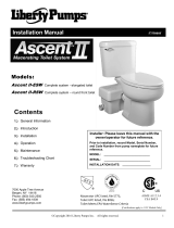
4.2 - DISASSEMBLY FOR LITTLE INTERVENTION
As the unit is connected to the water and electrical supply,
it is important to check that the following actions have been
taken before removing the unit:
1. If possible, close off the water supply to the tank and close
the ball or gate valve on the outlet pipe.
2. Pull the electrical cord out of the receptacle before
removing unit.
3. Empty out as much water as possible from the toilet tank
and the toilet bowl.
4. Disconnect toilet from unit. Remove toilet bowl and set
aside against a wall to prevent from tipping over.
5. The use of a dry/wet type vacuum cleaner might assist you
greatly in removing the residual water in the bowl or
macerating unit.
6. When you have to remove the macerating unit, carefully
disconnect the inlet drainpipes, (there might be residual
water inside).
7. Side inlet valves clogged: remove the sleeves and use a
screwdriver to free or clean the rubber flap if necessary.
8. For Sani 3, use the WC inlet to remove a foreign object with
the help of a folded wire.
4.3 - RETURN AND REPAIR OF THE MACERATING UNIT
In the event that the unit needs to be returned for service,
please call for possible options, or to inquire about an
authorized repair shop in your area. When you are required to
return the macerating unit to the manufacturer, please ensure
that prior to shipping, the unit has been cleaned and
disinfected inside and outside. A labour charge will be in
effect for cleaning ($50.00). Before returning any unit, a return
authorization is needed from the manufacturer. Units returned
without prior RGA number will be refused and returned collect.
If you return the macerating unit in its original packaging,
please remove the discharge elbow and retain until
re-assembly. If elbow is not removed, damage due to
shipping might occur.
Please package the macerating unit properly with adequate
shock absorbent material around it.
Send this package prepaid to the manufacturer, making sure
to insure against loss and/or transit damage, (the amount of
$300.00 will suffice).
If any repairs are done outside the warranty period, or when
the user has damaged the macerating unit, you will be
apprised of repair costs. All repair work will be conducted on
a pre-paid basis only.
5
MAINTENANCE (for qualified personnel only)
5.1 - See paragraph 4 PROBLEM SOLVING (4.1 and 4.2)
5.2 - If you need to open the macerating unit, first release the
discharge elbow, unclip the lid and pull up lid. In some cases
the lid might be stuck to the case very tightly, (during
assembly soapy water is used which dries up in time).
If required to remove motor from the case, unscrew motor retai-
ning screws. Also release the insulator cable to the lid. Lift out
motor assembly. Do not attempt to dismantle the motor assem-
bly itself as it is “clipped” together. These clips may break off
when trying to unclip them. In addition to damaging the clips
the motor seals may be damaged when the lid is removed
from the motor housing. The motor is filled with dielectric oil,
do not remove it or replace with regular oil. Please note, the
distributor purposely does not keep seals, bearings, or oil in
stock.
5.3 - SANI 3 FUNCTION CHECKUP IMPELLER
Invert motor to gain access to pump chamber at the base.
Unclip pump cover plate from motor housing.
Unscrew the pump impeller counter clockwise, releasing it
from the spindle (block the spindle to unscrew). Clean pump
chamber and discharge elbow and pipe work to ensure no
blockage exists. Check that drive shaft rotates freely. Also
check that the air relief-hole in the wall of the chamber is
clear.
5.4 - CAUTIONARY NOTE
Do not immerse unit totally in water. Do not let water enter the
electrical cord entrance opening.
5.5 - REASSEMBLY OF THE LID
When replacing the lid grease the rubber gasket lightly with
soapy water or dishwasher liquid. (Do not use Vaseline as this
may expand the neoprene materials).The gasket must be
inside the lid first. Start by pushing the lid down at the cord
side first, then work your way around and tap on the lid with a
rubber mallet or bloc.
notice SANI3.indd 6 30/11/10 10:32:45

6
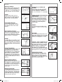
ADVICE
PIPE SUPPORTS
All sanitary pipe work must be
supported, in accordance with the pipe
manufacturer’s recommendations.
Avoid dipping or trapping, which may
cause the build up of residual “solids”
and sub- sequent blockage.
BENDS
Where possible long sweeping bends
should be used. Do not use short
elbows. If sweeping 90° elbows are not
available use two 45° elbows to make
a 90° turn.
VERTICAL INSTALLATION FIRST
If vertical lift is required, this must
precede the horizontal pipe run.
DIRECTLY VERTICAL
All vertical lifts should rise as directly
above the unit as possible, allowing
only for the need to clear the toilet
tank. Any initial horizontal pipe run
from the unit, prior to a vertical lift
should not exceed 12-18 inches.
EASY ACCESS
The unit should be accessible and
removable in the event of maintenance
being required. During the installation
a full-port ball valve should be installed
at the base of any vertical discharge
pipe work from the unit to allow easy
service of the unit.
GRAVITY FALL
The unit accepts wastewater by
gravity; it does not “vacuum” in water.
All inlet pipe work must have a positive
gravity fall, (
1/4" per foot). All horizontal
piping from the macerating unit must
also have a positive gravity fall to allow
free drainage when the pump stops.
NO DIRECT FALL
Where the point of discharge into the
soil stack is significantly lower than the
base of the unit, a vacuum relief valve
may need to be fitted at the highest
point in the pipe run in order to avoid
siphonage of the water seal.
THREE FEET MINIMUM
The macerating unit must be installed
at least 3 feet from the soil stack. This
will allow the macerator to operate for
an adequate period of time to ensure
efficient waste reduction.
SOIL STACK CONNECTION
All discharge pipe work must be
connected to the soil stack by an
appropriate and approved connection.
A “tee” or ”y” fitting as shown is
preferable.
NO DIAGONAL “UPHILL” PIPE
RUNS
All discharge pipe work from the
unit should run either directly vertical
upwards from it or in a horizontal plane
(with a small gravity flow) to the point of
discharge. Pipe work should not be
installed with diagonal upward slope
from the unit to the point of discharge.
PIPE WORK
All pipe work should be either copper,
PVC or CPVC (Do not use flexible
pipes). Hangers should not be less
than three feet apart to prevent pipe
rattling.
DISCHARGE
Never discharge directly into an open
drain, fixture, manhole or rainwater
drainpipe. It is illegal for it constitutes a
health hazard. Direct connections into
sanitary waste systems only, shall be
acceptable.
FREEZING
Ensure all pipe work susceptible to
freezing is adequately insulated or
heated. In unheated buildings, the
toilet, piping and macerating unit must
be properly winterized with “RV or
plumbers” anti-freeze or drained
completely.
ELECTRICITY
Before attempting any maintenance or
servicing, the unit must be disconnec-
ted from the power source. The mace-
rating system must be connected to a
Ground Fault Circuit Interrupter (GFCI).
notice SANI3.indd 7 30/11/10 10:32:47

When claiming a warranty repair we will need the information you have written down below. Please ensure that you have all
particulars available when requesting warranty work.
Name Owner: ___________________________________________________________________________________________________________
Installation Address: _____________________________________________________________________________________________________
Purchased From: ________________________________________________________________________________________________________
Installed By: ____________________________________________________________________________________________________________
Date of Purchase: _______________________________________________________________________________________________________
________________________________________________________________________________________________________________________
Serial Number: __________________________________________________________________________________________________________
Date of Manufacture: _______________________________________________________________________ (see manufacturers’ tag on unit)
7
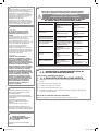
TROUBLE SHOOTING GUIDE
PROBLEM
Motor turns normally but the water
evacuates slowly from the bowl,
(flush incomplete).
Waste build up in bowl.
The macerating unit does not start
up. Water does not evacuate.
The motor hums but does not turn
the water does not evacuate.
Water goes down slowly and motor
works intermittently.
The water evacuates from the toilet
but the motor runs for a very long
time, thermal overload activates.
After evacuation the motor engages
several times in succession before it
stops completely.
Motor turns noisily without stopping
or pumping.
After evacuation the motor starts,
stops, and re-engages indefinitely.
For Sani 3, the motor turns with a
rattling noise.
Water backs up into shower tray or
bathtub.
CAUSE
Discharge pipe blocked or valve not
vented properly.
Inadequate water supply from
reservoir.
Power supply off. Thermal overload
cut out.
Foreign body blocking the macera-
ting blades. Defective capacitor.
Clogged up (sanitary napkin, news-
paper, plugged breather hole etc.).
Kinked/blocked discharge pipe,
damaged membrane, defective
impeller, and partially blocked pump.
Water siphons back into the
macerating unit. Check valve
is not functioning properly.
Siphonage or insufficient back
pressure in discharge pipe, causing
airlock. Foreign object.
Water leaking from reservoir into
bowl. Faulty non-return check valve.
Solid item has fallen into the grille of
the macerating unit.
Inadequate gravity-fall into macera-
ting unit or blockage in drain piping.
Faulty inlet control flap.
REMEDY
Clean out the piping and air breather
hole.
Check and/or adjust water level in
reservoir.
Wait for thermal overload to engage
(approx. 20 min).
See “dismantling”.
Flush 3 or 4 times to clear. Cleaning
or dismantling may be required.
Clean out the breather hole.
Check installation.
Flush once or twice with clean water
to clear valve or remove valve to
clean.
Modify discharge pipe run to
eliminate siphonage and/or increase
backpressure. E.g. reduce pipe size,
put extra bend in run. Remove
foreign object.
Check flush valve. Check and clean
non-return check valve.
Clear object from grille area.
1
/4” per foot gravity fall minimum
into macerating unit from other sani-
tary fixtures.
Clean out the flap.
IMPORTANT
notice SANI3.indd 8 30/11/10 10:32:47

LIMITED WARRANTY
2 Year Warranty from Date of Purchase
Subject to the terms and conditions set out below, SFA-SANIFLO INC., (hereafter designated the as the
Company) warrants that it will repair or replace the product or any of its component parts, at the
Company’s discretion if it deems that the product or part it is defective or does not meet the rated
performance due to a maufacturing or material default.
If replacement is to be issued, this will only be extended to the first 180 days starting from the date of
purchase. Warranty repairs will apply after such date up to the warranty’s date of conclusion.
TERMS AND CONDITIONS
The conditions of this warranty are the following:
• The product must be installed in accordance with the use described in the enclosed manuals.
• The product must be connected to a single phase 120V, 60Hz electrical outlet and was not subject
to any negligence, accident or exposure to harmful products or substances..
• The alleged defect or fault must be reported either to the installer or to the Company during the
warranty coverage period.
• The warranty coverage period is valid for 2 years.
PART OR PRODUCT EXCHANGE
The product may be exchange without cost only at the sales outlet where it was purchased subject to
the following conditions:
•The customer must have an “authorized return number” from the manufacturer in order to validate
exchange.
•The customer must produce proof of purchase to validate exchange.
LIMITATIONS
1.Fill and flush mechanism are guaranteed as per OEM warranty only.
2.Vitreous china are guaranteed only for a factory defect.
3. Cost of disconnection and reconnection (ie labor charges) are not covered by the warranty and are
end-users responsability.
4. Cost of mail or freight when a part or parts of the system have to be repaired at the company are
not covered by this warranty.
5. In no event shall the company be reliable for any special, incidental or consequential damage, loss, or
injury of whatsoever nature or kind arising from or in connection with the product or any component
thereof.
6. The guarantee is transferable only when the product remains at the same premises as where it was
installed initialy.
Except as set forth in this Limited Warranty, the company disclaims all other warranties, express or
implied, with respect to the product or any component thereof including, but not limited to, all implied
warranties for merchantability and fitness for a particular purpose.
For Service and other inquiries, please call either of the addresses listed below.
United States Canada
SFA-SANIFLO INC.
SFA-SANIFLO INC.
105 Newfield Avenue, Suite A 1-685 Speedvale Avenue West
Edison, NJ 08837 Guelph ON
N1K 1E6
Customer toll free: 800-571-8191 Customer toll free: 800-363-5874 English
Customer toll free: 800-877-8538 French
Telephone: 732-225-6070 Telephone: 519-824-1134
Telefax: 732-225-6072 Telefax: 519-824-1143
Web Site: www.saniflo.com Web Site: www.saniflo.ca
notice SANI3.indd 9 30/11/10 10:32:47

GENERALIDADES
El sistema de trituración de su producto esta
instalado en una caja especialmente estudiada
para un inodoro de salida horizontal.
Este triturador es un producto diseñado según
las normas siguiendo un control de calidad
permanente dentro de una fábrica que tiene la
certificación ISO 9001 versión 2000 por AFAQ.
El buen funcionamiento del aparato exige una
atención muy escrupulosa al manual a la hora
de realizar la instalación y de su mantenimiento.
Prestar especial atención a los símbolos
siguientes :
" "
Aviso de posible peligro para las
personas, en caso de no respetarlo,
" "
Aviso de la existencia de un riesgo de
origen eléctrico,
"
ATENCIÓN
"
indicación cuya no
observación podría entrañar peligro para el
funcionamiento del aparato.
Este aparato cuenta con las últimas
innovaciones tecnológicas en materia acústica.
Para sacar el máximo partido de esta nueva
generación de aparatos, es importante seguir los
consejos de montaje descritos en la sección .
7
1
INSTALACIÓN
ATENCIÓN : este aparato debe conectarse a
un inodoro de salida horizontal.
El aparato debe de estar en la misma sala / habi-
tación que el WC y los otros aparatos sanitarios.
El aparato debe de instalarse de manera que el
acceso sea facil para control y mantenimiento.
Se suministra con unos dispositivos de fijacion
que le impiden rotar o moverse.
Para optimizar los últimos desarrollos técnicos
en materia acústica incluidos en este aparato,
es importante :
• instalar el depósito de forma que no toque
ninguna pared de la sala / habitación,
• posicionar el depósito sobre un suelo lo más
plano posible, para permitir el adecuado
funcionamiento de los contactos anti vibratorios,
• fijar correctamente el tubo de evacuación
evitando que las distancias entre las fijaciones
sean superiores a tres pies.
7
CONEXIÓN AL WC
• Lubricar el extremo de la salida del wc
con jabón líquido o grasa de silicona,
• Ensarte la abrazadera suministrada en la
salida de la cubeta,
• Alinear el fuelle con la salida horizontal del
WC,
• Insertar el fuelle en la salida horizontal del
WC,
• Colocar la abrazadera en el extremo de la
goma fuelle y luego apretarla con un
destornillador.
Una vez instalado el aparato, fíjelo al suelo
con los 2 tornillos suministrados.
Si la fijación al suelo se efectúa con
2 plaquetas, fíjelas primero bajo el depósito
antes de colocarlo sobre el suelo.
¡ ATENCIÓN !
La cisterna, así como los grifos de cualquier
otro sanitario conectado a un triturador, deben
ser perfectamente estancos. Una fuga,
aunque sea leve, provoca arranques
inesperados del triturador.
CONEXIÓN A LOS SANITARIOS
Ver la fig. n°
(Cf ficha técnica) para las posibles conexiones
de los aparatos sanitarios.
ATENCION: para conectar una ducha/bañera,
procurar elevar el fondo 6 pulgadas como
mínimo(8 pulgadas es recomendada)
CONEXIÓN EVACUACIÓN
(Cf ficha técnica fig. ).
• SANI 3
oriente el codo de salida en el sentido
deseado, a continuación utilice el tubo de
plástico, sin doblarlo, para conectarlo al
conducto de evacuación. Si es necesario,
utilice el racor 20/32 suministrado.
• SANI 3
1 Su aparato está e
quipado con un gran
codo de caucho blanco:
- Orientar la abertura de la válvula anti-
retroceso hacia el lado de la salida
prevista, girándola con una llave o extra-
yéndola e introduciéndola en el extremo
de la salida de caucho del triturador.
- Orientar el codo de salida , introducirlo
en la durita de caucho y apretarlo con
una abrazadera .
2. Su aparato está equipado con un codo de
plástico y un manguito flexible:
- Introducir el manguito en el codo. Fijarlo
con una abrazadera .
- Orientar este conjunto e introducirlo en la
durita negra (7c). Fijar la base del codo
con una abrazadera .
- Si es necesario, cortar el extremo del
manguito para adaptarlo al tubo de
evacuación y utilizar una abrazadera
o .
DC
B
B
A
B
7c
7b
7a
7b
7c
E
• Evacuación vertical ascendente :
Procurar que el conducto ascendente quede
a la derecha del aparato. La evacuación
debe tener lugar gravitatoriamente
(pendiente del 1%),
• En la parte inferior del conducto de evacuación
ascendente prever una purga que permita el
vaciado en caso de intervención,
• Para evitar efecto sifón :
- instalar una válvula aireación (tipo Nicoll o
similares) en la parte alta, o
- aumentar el Ø del conducto horizontal,
• La evacuación del aparato SFA debe
acoplarse al bajante de las aguas residuales
mediante un racor usual en el comercio,
• Tuberías : protegerlas contra las heladas
mediante aislantes adecuados.
IMPORTANTE: Utilice codos con gran radio
de curvatura para mejorar el desague. Si no
es posible, utilice dos codos de 45 grados
para crear el angulo de 90 grados.
Se recomienda instalar un sistema de alarma
externo Sanialarm, el cual avisará en caso
de disfunción del triturador. En ciertos
aparatos, el punto de taladrado está indicado
en la tapa.
CONEXIÓN ELÉCTRICA
Efectuar la conexión eléctrica sólo
una vez llevados a cabo todas las
conexiónes definitivas
La instalación eléctrica debe ser realizada por
un profesional cualificado en electrotécnica.
El aparato debe estar colocado de forma que
el enchufe de corriente sea accesible.
El circuito de alimentación del aparato debe
estar conectado a tierra (Clase I) y protegido
por un disyuntor diferencial de alta sensibilidad
(30 mA) calibrado a 10 A minimo.
La conexión
debe servir
exclusivamente para
la alimentación del aparato. En caso de duda,
hacerlo controlar por un electricista cualificado.
Si el cable de este aparato está dañado, debe
ser reemplazado por el fabricante o por su
servicio postventa, a fin de evitar cualquier
peligro.
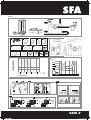
LISTA DE PIEZAS
SUMINISTRADAS :
Ver fig. n° (Cf ficha técnica).
2
2
DIMENSIONES Y
VOLUMEN :
Ver fig. n° (Cf ficha técnica).
3
3
AMBITO DE APLICACION Y
DATOS TECNICOS :
Este aparato es un triturador-bombeador
especialmente diseñado para evacuar las
aguas usadas procedentes de un inodoro y
de los aparatos sanitarios mencionados en la
fig. n° (Cf ficha técnica).
Es para uso doméstico.
Tiene un alto nivel de cualidades técnicas,
seguridad y fiabilidad siempre que se cumplan
atentamente todas las reglas de instalación y
mantenimiento descritas en la presente nota.
Hallará los datos técnicos en la fig. n°
(Cf ficha técnica).
1
8
4
CURVA DE RENDIMIENTOS :
Ver fig. n° (Cf ficha técnica).
5
5
ALTURA Y LONGITUD DE
EVACUACIÓN :
Las combinaciones posibles entre altura y
longitud de evacuación figuran indicadas en la
fig. n° (Cf ficha técnica).
6
6
• Este aparato debe ser conectado a un sistema
de ventilacion. Tiene dos conexiones en la parte
posterior de la tapa: una conexión de 1-1/2” y
otra de diametro menor. La unidad debe estar
conectada al sistema de ventilacion de acuerdo
a las leyes locales de plomeria. Utilice la
conexión de caucho e instalelo en la entrada
de 1-1/2”. Asegure esta conexión con las
abrazaderas que son parte de el juego de
conexiones proporcionadas. Luego, conecte el
tubo de ventilacion.
IMPORTANTE:
Esta prohibido usar sistemas
de ventilacion que solo alimentan aire en una
direccion como un AAV o valvulas mecanicas
que solo dejan entrar el aire y no salir de el
sistema. La presion debe ser la misma
adentro y afuera de el aparato.
8489 BASE NOTICE BROY:5121 BASE NOTICE BROYEUR 3/11/09 11:56 Page 10
CONEXIÓN AL SISTEMA DE VENTILACION
7c
La junta de goma (No 35 – esquema de la
bomba) suministrada será utilazada para
conectar la bomba con la parte posterior de la
taza de el hinodoro. La parte mas pequeña
deberá ser estirada para que pueda ser
instalada en la parte frontal de la bomba.
Una vez instalada, esta junta deberá ser
asegurada por medio de la correa de plastico.
El otro lado tendra que ser conectada a
la posterior de el hinodoro. La conexion
tendra que ser asegurada usando la
abrazadera proporcianada.
CONSEJOS TÉCNICOS PARA
LA EVACUACIÓN
(cf. ficha técnica fig. ).
• Evitar los “puntos bajos” en el conducto de
evacuación manteniéndolo recto mediante
abrazaderas. Prever una pendiente
descendente de un 1% para la parte de
evacuación “horizontal”,
7e
7e
notice SANI3.indd 10 30/11/10 10:32:48

MANTENIMIENTO
ANTES DE CUALQUIER
INTERVENCIÓN DESCONECTAR
EL TRITURADOR DE LA RED
ELÉCTRICA.
El triturador no necesita un mantenimiento
particular.
12
UTILIZACIÓN Y PRECAUCIÓN
¡ ATENCIÓN !
En caso de ausencias prolongadas
(vacaciones) es obligatorio cerrar la
alimentación general de agua de la
vivienda.
Los baños equipados con un triturador deben
utilizarse como un WC clásico y su
mantenimiento es mínimo. El triturador
arranca automáticamente en cuanto se
alcanza determinado nivel de agua en la caja.
Esta es una unidad para uso domestico.
Para las evacuaciones horizontales :
• Respetar una pendiente del 1%,
• Evitar los puntos bajos en la canalización.
La tubería de evacuación debe desembocar
por encima de la canalización de evacuación
principal aunque la instalación tenga una o
varias válvulas antirretorno.
¡ ATENCIÓN !
La garantía cubre únicamente la
evacuación de papel higiénico, materia
fecal y aguas sanitarias. Cualquier avería
producida por el bombeo de cuerpos
extraños tales como algodón, tampones
higiénicos, compresas, toallitas, productos
alimentarios, preservativos, cabellos,
objetos de metal, de madera o de plástico,
o bombeo de líquidos como disolventes o
aceites no será cubierta por la garantía.
Este aparato no está destinado a personas
(incluidos niños) cuyas capacidades físicas,
sensoriales o mentales estén limitadas, como
tampoco a aquéllas
que
carezcan de la
experiencia o el conocimiento del mismo,
salvo que se encuentren bajo supervisión
y reciban las instrucciones necesarias para
utilizar el aparato, con la ayuda de una
persona responsable de su seguridad.
Supervisar a los niños y vigilar que no
jueguen con el aparato.
10
LIMPIEZA / DESINCRUSTACION
Para limpiar y desincrustar la trituradora y la
cubeta, utilizar frecuentemente un producto
desincrustante sanitario.
• Desconectar la toma eléctrica del triturador,
• Introducir en el inodoro una dosis de producto
desincrustante,
• Dejar reposar durante varias horas,
• Volver a conectar la toma eléctrica del
triturador,
• Lavar accionando 2 veces la cisterna.
Esta operación debe ser realizada con una
frecuencia de una vez cada 6 meses, pero debe
ser efectuada en función de la dureza del agua.
11
POSIBLES INTERVENCIONES
13
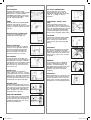
REMEDIOS
• Póngase en contacto con el servicio
técnico oficial
• Esperar la puesta en marcha
• Revisar cada uno de los elementos
conectados,
• Limpiar o cambiar la válvula
anti-retorno
• Destapar el respiradero
• Mirar la instalación
• Si no, consultar al SAT
• Enchufar el triturador a la corriente,
• Si no, consultar al SAT
• Extraiga el cuerpo extraño
(ver sección )
• Si no, consultar al SAT
• Revisar la instalación
• Limpie las clapetas (ver sección )
• Si no, consultar al SAT
14
14
CAUSAS
• El aparato ha funcionado durante
demasiado tiempo (corte térmico de
seguridad)
• Problema eléctrico
• Los sanitarios conectados pierden
agua
• La valvula anti-retorno pierde
• El respiradero esta tapado
• La altura o la longitud de evacuación
es muy larga o tiene muchos codos
• La tapa bomba está atascada
• Triturador no enchufado
• Enchufe defectuoso
• Problema del motor o del sistema
de control
• Motor bloqueado por un cuerpo
extraño
• Problema del motor o del sistema
de control
• Ducha instalada demasiado baja con
relación a la trituradora
• Clapetas de las entradas laterales
obstruidas
ANOMALIAS
• El aparato se para
• El triturador se pone en marcha
intermitentemente
• El motor funciona con sacudidas y el
agua desciende lentamente en la taza
• El motor gira correctamente pero no
se para o gira lentamente
• El motor no arranca
• El motor gira con un ruido de carraca
pero no gira
• Retorno de agua turbia en la ducha
(aparatos con entradas laterales)
EN CUALQUIER CASO, DESCONECTE
LA TOMA ELÉCTRICA DE LA TRITURADORA
DESMONTAJE
D
ESENCHUFAR LA TOMA DE CORRIENTE ANTES DE
REALIZAR CUALQUIER INTERVENCI
Ó
N
CÓMO SACAR EL TRITURADOR DEL INODORO
Desenchufar la toma de corriente eléctrica,
Cerrar el grifo de la cisterna. Retirar la máxima cantidad posible de agua del sifón del
inodoro,
Extraer el tubo de evacuación del codo,
Retirar las conexiones a los sanitarios,
Retirar los dos tornillos de fijación al suelo,
Destornillar la abrazadera y separar el aparato del inodoro empujando el manguito hacia
el aparato y sacándolo de lado.
ANILLAS DE LAS ENTRADAS LATERALES OBSTRUIDAS
Extraiga los manguitos y con un destornillador extraiga las anillas de caucho.
14
Algunas de las averías del triturador son menores. Puede usted areglarlas.
Para ayudarle a diagnosticar el problema, ayúdese del diagrama siguiente.
A
C
D
B
E
F
PARA CUALQUIER OTRO PROBLEMA QUE REQUIERA LA APERTURA
DEL APARATO, DIRÍJASE AL SERVICIO TÉCNICO OFICIAL
8489 BASE NOTICE BROY:5121 BASE NOTICE BROYEUR 3/11/09 11:56 Page 11
PUESTA EN MARCHA
Una vez efectuadas las conexiones eléctricas e
hidráulicas, tirar una vez de la cadena ; el
aparato se pone en marcha automáticamente y
funciona entre 5 y 10 s, según la altura de
evacuación. Si el aparato funciona más de 20 s
comprobar que el conducto de evacuación no
esté aplastado (probable freno) o que el
respiradero no esté obstruido.
Tirar varias veces de la cadena. El paso del
inodoro debe ser estanco. Asimismo, comprobar
la estanqueidad de las conexiones a los otros
sanitarios : lavamanos, ducha, bidet, lavabo.
9
notice SANI3.indd 11 30/11/10 10:32:49

6
AVISO
APOYO DE TUBERIA
Toda la tuberia sanitaria de descarga
debe ser asegurada y apoyada de
acuerdo con las recomendaciones de
el fabricante. Es recomendado usar
soportes dejando 3 pies de longitud.
CURVAS
No utilice codos cortos. Si no es
posible conseguir codos de 90° de
larga curvatura, usar dos codos de
45° para hacer una vuelta de 90°.
INSTALACION VERTICAL
Si la instalacion es de descarga
vertical, es requerido que esta des-
carga debe preceder la de el tubo
horizontal.
DIRECTAMENTE VERTICAL
Todas las descargas verticales deben
comenzar lo mas pronto posible y lo
mas cerca a la salida de el sistema.
Ningún tubo de salida inicial horizontal
deberia exceder 12-18 pulgadas.
ACCESO
La unidad debe ser accesible en caso
de mantenimiento. Durante la instala-
ción, una válvula debe ser instalada en
la base de la tuberia de descarga de la
unidad para permitir servicio fácil de la
unidad.
CAIDA DE GRAVEDAD
La unidad acepta el desague por caida
de gravedad; no succiona el agua.
Toda tuberia que descarga hacia el
sistema debe tener una caída positiva
de gravedad, (1/4’’ por pie). Toda la
tubería de descarga horizontal tam-
bién debe tener una caída positiva de
gravedad para permitir la caida de el
desague cuando la bomba no este en
operacion.
NINGUNA CAIDA DIRECTA
Dónde el punto de descarga es
apreciablemente más bajo que la base
de la unidad, una válvula de alivio de
vacío puede ser necesitada e instalada
en el punto más alto en el tubo de
descarga para evitar siphonage del
sello de agua.
MINIMO DE TRES PIES
La unidad debe tener por lo menos 3
pies de tuberia de descarga entre el
sistema y el desague. Esto permitirá
la unidad operar para un espacio de
tiempo adecuado asegurando reduc-
ción eficiente de el desecho.
CONEXION A LA TUBERIA DE
DESAGUE
Toda conexion de la descarga debe
ser conectado al desague por una
conexión apropiada y aprobada. Un
‘‘tee’’ o una conexion ‘‘Y’’ es preferible.
TUBERIA EN DESCARGA DIAGONAL
(ASCENDENTE)
El tubo de la descarga de la unidad
debe correr o directamente vertical
hacia arriba o en posicion horizontal
(con un pequeño flujo por gravedad).
La tuberia de descarga no debe ser
instalada con corridas diagonales
(cuesta arriba).
TUBERIA
La tuberia de descarga debe ser de
PVC, CPVC o cobre. No utilice tubos
flexibles.
DESCARGA
Nunca descargue directamente en un
desaguadero abierto, tubo de desagüe
de boca de alcantarilla, etc. Es ilegal y
constituye un peligro para la salud.
TUBERIAS A BAJA TEMPERATURA
Asegure que toda la tuberia suscepti-
ble a bajas temperaturas sea insulada
adecuadamente. En lugares donde la
unidad, la tuberia y el inodoro estan
bajo estos tipos de temperaturas,
estos deben ser acondicionados para
el invierno apropiadamente con liquido
anticongelante de ‘‘RV o de plomeros’’.
CONEXION ELECTRICA
Antes de procurar cualquier mante-
nimiento o atender a la unidad, esta
debe ser desconectada de la fuente
de electricidad. El sistema debe ser
conectado a un Interruptor de Circuito
del Defecto del Suelo (GFCI).
notice SANI3.indd 12 30/11/10 10:32:51

GARANTIA LIMITADA
2 AÑOS DE GARANTIA COMENZANDO DE LA FECHA DE COMPRA
Sujeto a los términos y condiciones mencionadas en este documento, SFA-SANIFLO S.A., (designada
de ahora en adelante como la Compañía) garantiza la repararacion o reemplazará el producto o cual-
quiera de sus partes que lo integran, en la discreción de la Compañía si se cree que el producto sea
defectuoso o no encuentra el desempeño valorado debido a un defecto material.
Si el reemplazo es de ser autorizado, este sólo será extendido a los primeros 180 días que comienzan
de la fecha de la compra. Las reparaciones bajo garantía aplicarán después de tal fecha hasta la fecha
de la conclusion de garantía.
TERMINOS Y CONDICIONES
Las condiciones de esta garantía son las siguientes:
• El producto debe ser instalado de acuerdo a las instrucciones de este manual.
• El producto debe ser conectado a: 120V (1-fase), 60 Hz toma de electricidad y que no este sujeto
a ninguna negligencia, ni la exposición a productos de substancias perjudiciales.
• El defecto pretendido debe ser reportado al instalador o a la Compañía durante el período de
alcance de garantía.
• El período de alcance de garantía es válido durante 2 años.
CAMBIO DE PRODUCTO
El producto puede ser cambiado sin costo sólo donde fue comprado sujeto a las condiciones
siguientes:
• El cliente debe tener un “numero de autorizacion de regreso” del fabricante para validar cambio.
• El cliente debe producir comprobante de compra para validar cambio.
LIMITACIONES
1.Los mecanismos dentro de el tanque de agua, son garantizados de acuerdo a la garantía de el
fabricante de origen.
2.Las unidades compuestas de porcelana son garantizadas sólo por un defecto de fábrica.
3. El costo de desconexión y reconexion (ejemplo: los cargos por trabajo) no son cubiertos por la
garantía y son responsabilidad de los usuarios.
4. El costo de correo o envio cuando una o mas partes del sistema tienen que ser reparadas en la
compañía, estos cargos no son cubiertos por esta garantía.
5. En ningún acontecimiento la compañía puede ser implicada por algún daño, pérdidas, o causas
especiales de la naturaleza que surgen y esten en conexion con partes o componentes de este
sistema.
6. La garantía es transferible sólo cuando el producto se queda en el mismo local de donde fue in-
stalado inicialmente.
Sino como expuesto en esta Garantía Limitada, la compañía renuncia a todas las otras garantías,
expresada o implicada, con respecto al producto o ningún componente del mismo incluyendo, pero
no limitado a, todas las garantías implícitas para el comerciante y la salud para un propósito particular.
Para servicio y otras indagaciones, llame por favor a cualquiera de los numeros que se encuentran
abajo.
Para servicio y otras indagaciones, por favor llame a cualquiera de los numeros de abajo.
United States Canada
SFA-SANIFLO INC.
SFA-SANIFLO INC.
105 Newfield Avenue, Suite A 1-685 Speedvale Avenue West
Edison, NJ 08837 Guelph ON
N1K 1E6
Customer toll free: 800-571-8191 Customer toll free: 800-363-5874 English
Customer toll free: 800-877-8538 French
Telephone: 732-225-6070 Telephone: 519-824-1134
Telefax: 732-225-6072 Telefax: 519-824-1143
Web Site: www.saniflo.com Web Site: www.saniflo.ca
notice SANI3.indd 13 30/11/10 10:32:51
-
 1
1
-
 2
2
-
 3
3
-
 4
4
-
 5
5
-
 6
6
-
 7
7
-
 8
8
-
 9
9
-
 10
10
-
 11
11
-
 12
12
-
 13
13


en otros idiomas
- English: Saniflo 039 Operating instructions
Artículos relacionados
Otros documentos
-
 Liberty Pumps ASCENTII-RSW Manual de usuario
-
 Mediterraneo 7001733 Guía de instalación
-
THETFORD SANI-CON El manual del propietario
-
-
DANCO 10772 Guía de instalación
-
-
-
SANIBROY Sanicompact Silence Eco+ Bathroom Toilet Manual de usuario
-
Keystone Model FC Twin Plate IOM El manual del propietario
-
Sioux Chief 250-12A Guía de instalación

