
www.GEAppliances.com
©
Safety Information ........... 2
Installation Instructions ...3-1 o
Step-by-step instructions .... 6-10
Operating Instructions
Breaking a salt bridg_ ........ 19
Cleaning the nozzle and
venturi assembly ............ 19
Features ................... 13
Service .............. 11, 14-16
V(ater softener system ..... 11-16
Care and Cleaning ......... 17
Troubleshooting Tips ..... 18-20
Consumer Support
Consumer Support . . .Back Cover
Parts list/catalog ......... 92-25
V_'arranty (U.S.) ............. 96
_'arrantv (Canada) .......... 97
Water
Softening
System
Sistema
ModelGXSF27£
Suavizante
de Agua
Modelo GXSF27E
La secci6n en espa#ol empieza en la pagioa 29
System tested and certified by NSF International against NSF!ANSI Standard 44 fl)r the
chemical reduction (laims specitied on the per/brmance data sheet.
Sistema probado y certiticado pot NSF International contra norma 44 de NSF/ANSI para
las afirmaciones de reduccidn de los productos qufmi(os especi/icadas en la hoja de datos
de flmcionamiento.
Write themodelandserial
numbers here:
Model #
Serial #
To find these numbers, lift
the cover and look on the
rim below the control panel.
7247182 215Cl173P009 49-50150 02-05Jfl

IMPORTANTSAFETYINFORMATION.
READALLINSTRUCTIONSBEFOREUSING.
WARNING!
For your safety, the information in this manual must be followed to minimize the risk of electric shock,
property damage or personal injury.
SAFETYPRECAUtiONS
_: Check and cmnl)ly with vour state and local
codes. You must tollow ti/ese guidelines.
::Ji::Use care when handling the water softening
s_:stem. Do not turn upside down, drop, drag
or set on sharp protrusions.
?_:Water softening systems using sodimn chloride
(salt) for recharge add sodium to the water:
Persons on sodium restricted diets should consider
the added sodium as part of their overafl intake.
Potassium chloride can be used as an alternative
to sodium chloride in your softener
The _ater softening system _orks on 24 xolt-60 Hz
electrical power only. Be sure to use only the
included transformer
_: Use clean water softening salts only, at least
99.5% pm'e. NUGGET, PEI,I,ET or coarse
SOLAR salts are recommended. Do not use rock,
block, granulated or ice cream making salts.
They contain dirt and sediments, or mush and
cake, and will create maintenance problems.
::Ji::Keep the salt hole cover in place on the softener
tmless servicing the trait or refilling with salt.
A WARNING:oo.o, use with water that is
microbiologically unsati _ or of unknown quality
without adequate disinfection befi)re or after
the system.
iJi::Transformer must be )luo,_ed into indoor
120 xolt, grotmded outlet only.
PROPERINSTALLAtiON
This water softening system must be properly installed and located in accordance with the Installation
Instructions before it is used.
_: Install or store where it will not be exposed to
temperatures beh)w fl'eezing or exposed to any
type of weather: Water fi'eezing in the system will
break it. Do not attempt to treat water over 100°E
::Ji::Do n0tinstall in direct sunlight. Excessive sun or
heat may cause distortion or other damage to
non-metallic parts.
Properly ground to cent)tin with all governing
codes and ordinances.
Use only lead-free solder and flux for all sweat-
solder connections, as required by state and
federal codes.
_: Softener resins may degrade in the presence
of chlorine above 1 ppm. If you have chlorine
in excess of this ainount, you inay experience
reduced life of the resin. In these conditions,
you may wish to consider pro'chasing a (;E
point-ofent_ T household filtration system with
a chlorine reducing filte_:
A WARNING:Disc.,-d.lluilusedpax'ts
and packaging material alter installation.
Small parts remaining after the installation
could be a choke hazard.
Tile water softening s}:stem requires a minimum
water flow of three galhms per minute at the inlet.
Maximum allowable inlet water pressm'e is 125 psi.
]f daytime pressm'e is over 80 psi, nighttime
pressm'e may exceed the maximmn. Use a pressm'e
reducing \:dye to reduce the flow if necessarx:
READANDFOLLOWTHISSAFETYINFORMAtiONCAREFULLY.
SAVETHESEINSTRUCTIONS
2

Installation instructions.
A_ CAUTION: Certain plumbing skills are needed for installation. If you are unsure about
any part of the installation of this product, consult a professional plumber.
Unpacking and Inspection
Be sure to check the entire softener for any
shii)ping damage or parts loss. Also note
(lamage to tile shii)ping cartons. Contact the
transportation company for all damage and
loss claims. The ii/antlf_lCttli'ei" is not
responsible fl)r damages in transit.
Small parts needed to install tile softener are
packaged either in a bag or on a cardboard
sheet. To avoid loss of the small parts, kee I)
them packaged tmtil you are ready to use them.
Be StlYe not to discard components hidden in
packaging.
Important Installation Recommendations
Read entire manual. Failure to follow all guidelines and rules could cause personal injury or
property damage.
_: Before you 1)egin installation, read these
Installation Instructions completely. Then,
obtain all tile materials and tools you will
need to make the installation. Failm'e to
properly install the softener voids the
W[I IT[I n IV.
Maximum allowable inlet water pressm'e is
195 psi. If daytime pressure is over 80 psi,
nighttime pressure may exceed tile
maximmn. Use a pressure reducing wflve
if necessary: (Adding a pressure reducing
wflve may reduce tile flow.)
::Ji::Check local codes. Tile installation m ust
conform to them.
::Ji::In the Commonwealth of Massachusetts,
Plumbing Code 248 CMR shall be adhered to.
Consult with your licensed plumber.
::J?::Use only lead-h'ee solder and flux for all
sweat-solder connections, as required bv
state and federal codes.
_: Connect tile soliener to tile main water
supply pipe before or ahead of the water
heater. DO NOT RUN HOT WATER THROUGH
THESOFTENER.Temperature of water
passing through tile softener illtlst be
less than 120°F.
::Ji::Tile softener works on 24 volt-60 Hz
electrical power only. Be sure to use tile
included transformer. Be sure tile electric
outlet and transformer are in an inside
location to protect ['l'OlIl i/loisttlre.
_: See Where to Install the Softener section fl)r
more derails.
A WARNING:Do use with water
that is microbiologically tmsafe or of
tmknown quali W without adequate
disinfection befi)re or atier the system,
The water should be tested periodically
to verif)' that tile system is peril)truing
satistactorilv.
_: Use care when handling tile softener.
Do not ttlFn upside down, drop, drag
OI" set on shay l) l)I'otI'/Isions.
_: Small parts remaining after tile installation
could be a choke hazard. Discard safely.

Installation instructions.
Plan How YouWill Install the Softener
You must first decide how to mm in and out
pipes to the softener. I,ook at the house
main water pipe at the point where you will
connect the soiiener. Is the pipe soldered
coppe_; glued plastic or threaded galwmized?
What is the pipe size?
.4,WARNING:Use..l, le,,d.,ee
solder and flux to prevent lead poisoning.
See Yypical Installation Illustration, Fig. 1. Use
this as a guide when planning yore" particular
installation. Be sure to direct the incoming hard
water supply to the softener valve inlet fitting.
The valve is marked IN and OUT See illustration
on page 5 to help you prepare.
Where to Install the Softener
::Ji::Place the sottener as close as possible to a
sewer drain, or other acceptable drain point
or standpipe.
::Ji::It is recommended to kee I) outside thucets
on hard water to save sott water and salt.
_: Do not install the softener in a place \_here it
could fi'eeze. Freeze damage is not covered by
the warranty.
_: Do not install the softener where it would
block access to the water heater or access to
the main water shutott.
Put the softener in a place where water
damage is least likely to occur if a leak
develops. The manufacturer will not repair
or pay for water damage.
_: A 120-volt electric outlet is needed to plug
in the included transtormer. The sottener
has a 10 toot power cable. If the outlet is
remote (up to 100 filet), use 18 gauge wire
to connect. Be sure the electric outlet and
transformer are in an inside location, toprotect
from wet weather. Be sure the outlet is
unswit('hed to prevent accidental shutolt.
_: If installing in an outside location, you must
take the steps necessary to assure the sotiene_;
installation plumbing, wiring, etc., are as
well protected ti'om the elements (stmlight,
rain, wind, heat, cold), contamination,
wmdalism, etc., as when installed indoors.
Outdoor installation is not recommended, and
voids the warranty.
_: Keep the softener out of direct sunlight.
The sun's heat may distort non-metallic
parts and may damage the electronics.
Toolsand Materials Required for Installation
_: In and out fittings included with the softener
are 3/4" (nominal) Col)per sweat tubes.
You should maintain the same, or larger,
pipe size as the water supply pipe, up to the
sottener inlet and outlet.
Use the included bypass valve to install the
sottener. The bypass wflve allows you to turn
off water to the soltener fin" servicing, but
still have water in the house pipes. The in
and out fittings referred to above connect to
the bypass valve with the included nuts and
wash ers.
::Ji::Use coI)pet; brass or galwmized pipe and
fittings. Some codes may also allow CPVC
plastic pipes.
If additi(mal drain hose is needed tot wove
and salt tank drains, it can be ordered from
GE Parts at 800.626.2002.
::Ji::If a rigid wdve drain is needed to comply
with plmnbing codes, you can buy the parts
needed to connect a 1/2" coI)per tubing or
plastic pipe drain.
::Ji::Clean nugget or pellet water sottener salt is
needed to fill the brine tank, see Step 8 in
the Step-by-Step Installation Instructions.
4

Typical Installation Illustration
,_. HAl
Softwater
24V transf(
120-voltoutlet
Salt hole
cover
Brinewell
/V47_RP/PE
-_ "_'---Hardwater
"_-__...._L Hardwaterto
outsidefaucets
_ Union (not supplied) (2)
(_-_ Installation nut (2)
_ opper tube, 3/4" (2)
Washer (2)
INLET
Drain
_assValve
• Pullout for softwater service
• Pushin for bypass
NOTE:Fittingssuppliedarefor
3/4" copperplumbing.Ifyouhave
1" plumbing,do notusethe coppertubes
andnutsincluded.Buy1" NPTfemale
adaptersandconnectdirectlytothe
1" NPTmalethreadsofthe bypassvalve.
NOTE: See Drain Hose Connections section.
Fig. 1 CROSSOVER
Useif watersupplyflows fromthe left.
Includesingleor3-valvebypass.
Hard water
Softwater
Fromsoftener,
)utlet
,_ To softener
inlet
Optional 3-Valve Bypass Installation Illustration
Adapters forthis installation are not supplied with the softener.Toordertheseadapters,call GEParts800.626.2000.(Askfor Part#WS6OX10006.)
Softwater ,_..,_ ...... MAIN
Bypassvalve
120-voltoutlet ¢4
P_
24V I_l! Outletvalve
transformer
Salthole
Drain
Hardwaterto
I_RPIPE outsidefaucets
_-___-_ ____
.... _ Hardwater
Inlet valve
3-Valve BypassSystem
Forsoft waterservice:
• Openthe inlet and
outletvalves
• Closethe bypassvalve
Forbypasshardwater:
• Closethe inletand
outletvalves
(2) • Openthe bypassvalve
Coppertube,3/4" (2)
Washer(2)
Installation adapter (2)(see above)
NOTE:Fittingssuppliedarefor
3/4" copperplumbing.Ifyouhave
1" plumbing,donot usethecoppertubes
andnutsincluded.Buy1" NPTfemale
adaptersandconnectdirectly tothe
1" NPTmalethreadsof the adapter.
Fig. 2 CROSSOVER
Useif watersupplyflows fromthe left.
Includesingleor3-valvebypass.
Hardwater (_
C
Fromsoftener 1'
outlet
Softwater
_, Tosoftener
inlet
5

Step-by-step installation instructions.
i_g:Turn off the gas or electric suppl) to the water heateL in the possibilit} that the water _i_. 3A
heater ma} be drained while draining pipes.
i:g:Turn off the water supp]) to pipes to be cut and drain tile house water pipes,
i:g:Open both hot and cold timcets at tile lo_vst location possible.
NOTE:For easier installation, remove file top covei; Release 9 clips at rear of tile cove_:
Rotate coxvr ti)rward and lift up.
1.INSTALLBYPASSVALVE
• Remo_v plastic shipping plug and wire fi'om valve outlet.
NOTE:Besuretheturbine and '__;_;
supportarefirmlyin placeinthe I utlet
valveoutlet. Blowinto the valve _ Ta_blsn:p;_[
port and observe the turbine
for free rotation, t
• Push the b}pass vane (lubricate o4"ing seals with silicone g_'ease) into both ports of
the valve as shown in Fig. 3%
• Snap the 2 lm'ge plasdc clips in place, fi'om the top, down as sho_m in Figures 3A
ml(t 3B, Be sure they snap into place. Pull on the bypass valve to make sure it is held
securely in place.
Z MOVETHESOFTENERASSEMBLYINTOINSTALLATIONPOSITION
Drain
Fitting
Hg3B
SIDE
VIEW
i-c--- Clip
Be sure file installation suriiJce is lexel and smoofll. Sharp objects under the rank ma)
ptxxlcttxre it. If needed, place tile tmlk on a section of 3/4" thick (minimum) pb'_)od.
Then, place shims under the pl)'_)od as needed to level the softener
3.PLUMB "IN" AND "OUT" PIPESTOAND FROMSOFTENER
,&CAUTION:Obser.eall tle ca,.,,,lsas,o. o,nle.,lle anal
outlet phmlbing'. See illustrations on page 5. Fig.3C
• BE SURE INCOMING HARD WATER SUPPIX IS DIRECTED TO THE
SOFTENER VA[YE INLET PORT. If house water flow is from the left, use a
plumbing crossover as sho_m in Fig. 1, pag> 5. If house water flows up from tile
floor lexvl, ttxrn tile bypass valxe upside ctoxm as shoxm in Fig. 3C.
• If making a soldered copper installation, do all sweat soldering before connecting
pipes to the bypass valve. Torch heat will dmnage plastic pm'ts.
• _'\]len turning threaded pipe fittings onto plastic fittings, use care not to cross-thread.
• Use piI)ejoint compound on all exmrnal pipe threads,
• Supl)ort inlet and outlet phmlbing in some manner (txse pipe hangers) to keep the
weight off of the valve fittings. Fig. 4[
4 CONNECTANDRUN THEVALVEDRAINHOSE
O-ringseal goesinto
the outer grooveonly.
Theclip snapsintothe
innergroove(seebelow).
Bypass
valve
• Use file In'ovided drain hose (20' length included) to attach to the valxe drain
fitting. To keep wamr presstxre ti'om blowing the hose oft; use a hose clamp to secure
in place. Cut the necessm? length and use the remainder in Step 5.
• i z)cate the other end of the hose at a stfitable chain point (floor chain, sump,
launch 3 tub, etc,) that mrminams at the sewex: Check and comply with local codes.
IMPORTANT'.If more drain h()se is needed, it should be orctexed from GE Parts at
800.626,2002, The water softener will not work if water cannot exit this hose during
recharge.
• Tie or wire the hose in place at the chain point. High water pressure will cause it to
whip during the back-wash and thst rinse cycles of rechargv. Also provide an air gap
of at least 1½" between the end of the hose and the drain point. An air gap pre_vnts
possible siphoning of sewer water into the soflenex; if the sewer should "back-up."
• Elevating the chain hose ma) cause back pressure that could reduce the brine
draw during rechaxge. If raising the chain line overhead is reqtfired to get to the
drain point, measure the inlet water pressure to the softener first. For inlet pressures
between 20 and 50 psi, do not raise higher dlan 8' abo_e the floox: For inlet
6' presstxre above 50 psi, the drain line ma) be raised to a maximmn height of 14'.
Valvebody
inletor outlet
Clip
END
Bypassvalve
(pushall the way in)
Turnbypassvalve
upsidedownto
O_U connectto floor
levelplumbing
T
IN
Valvedrainhose
gap
FLOORDRAIN

#,4.CONNECTINGA RIGIDVALVEDRAINTUBE
To adapt a copper drain tube to the soiteneL use a hack_m to cut the barbed end fl'om the
drain fitting as shown in Fig. 4A. Rotale file drain fitting st) file cutting blade clears file xahe
housing u) pre\ent damage to valve. But a compression fitting (1/4" fi:male pipe thread x l/2"
O.D. robe) and needed tubing fi'om p)ur It)cadhardware store.
5.INSTALLTHEBRINETANKOVERFLOWRT"I'INGSANDHOSE
• Insert tt/e rubber gxommet into tile 3/4" diameter hole in tile brine tank sidewall as sho_ql in
Fig. 5.
• Push the end of tile hose adapter elbow into tile gxonm/et as shown in Fig. 5.
• Attach a length of hose (use remaining hose Ii'om Stop 4) to the hose adapter e/bo_. Use a
hose clamp to hold it in place.
• I_ocam tile other end of the hose at the drain point. DO NOT ELEVATE this hose higher than
the elbowson tile bdne rank.
IMPORTANT:DONOTTEEOVERFLOWHOSETOVALVEDRAINHOSE.
NOTE:This drain is %I" safieff only. If the cabinet (brine rank) should o\er-Iill with watel; tile
excess is carried m the drain.
6.INSTALLGROUNDINGCLAMP
If plumbing is metal, to maintain electrical gromld continuity in tile house cold water piping,
iusmll tile included gTotmd clamp as sho_n ill Fig. 6.
• (;lean pipe with emery paper in the area _dmre the clamp is to be iusmlled.
• Install grounding clamps as shoxnl, making sure damps fit li'eely arotmd pipe.
• Make sure lock x<@mris ill place.
• Handtighten scre_, then one more fll[I mrn with scre_ddver
NOTE:When repladng ml existing soltenel; also replace grounding clamps.
If removing soltener completel b hard-plumb the water line with same t_pe of pipes as the
original to assure plumbing inmgrit} and ground confimlit_ over the lile of the home.
Z FLUSHPIPES,EXPELAIRFROMSOftENERANDTESTYOURINSTALLATIONFOR
WATERLEAKS
CAUTION:To avoid water or air pressure damage to softener inner parts, be sure
to do the following steps in exact order.
• Fully open 2 cold soft water faucets nearby the softener.
• Place bypass valve in "bypass" position by puslfing the stem inwaxd.
• Fully open the house main water pipe shutoff valve. Observe a steady flow from both faucets
opened in step A, above.
• Place bypass valve in the "service" position I_NACTLYas follows. I@'EP SO_3" WATER
FAUCETS OPFN.
SLOWLY pull or slide the valve stem (out) towaxd the service position, pausing several times to
allow the softener to pressurize slowly.
• After about 3 minutes, open a HOT water faucet for 1 minute, or mlfil all air is expelled, then
dose. NOTE: If water appears cloudy or has salt}'"u_ste,allow to run for several more minutes,
or until cleaI:
• Close all water faucets.
• Check your plumbing won for leaks and fix rigbt awayif any axe fomld. Be sure to observe
previous caution notes.
• Tunl on the gas or eledric supply to the water beater. Light the pilot, if applicable.
Fig4A
1/4" NPTthreads
Cutbarbs
fromdrain
fitting
1/2" O.D.
coppertuhe
(notfurnished
Compressionfitting,
1/4" NPTX 1/2" O.D.tube
(notfurnished)
Bg5_
J
££_,,-_ Hoseadapter
e--- Hoseclamp
-_@°mmet/i Donotconnectto
] \\valve drainhose.
Overflow.i_&_
drainhose
I _ Tosewerdrain
Tovalveinlet
Fromvalveoutlet
7
8.ADDWATERANDSALTTOTHEBRINETANK
• LiR tile salt hole cove£ Add about 3 g'4llons of _<_terinto tile rank.
Do not add into the brineweg.
• Fig rank wifll NUGGET, PELI.ET or coarse SOI.AR wamr softener salt
with a purit_ of99.5% or hi0_er Do not use rock, block, gramdated
and ice cream-making salts, or salt with iron-removing additives
(except for Diamond (2I')rS_] _ Red"Out c'>brand salt). Maximum sdt
su)rage capacity is approximatel} 200 Ibs. Keep the salt hole co\er
closed unless set\icing the unit or refilling with salt.
NOTE:If the softener is installed ill a humid basement or other damp
area, it is bettor m flUthe tank with less salt, more frequently. Eight} to
100 Ibs. of salt willlast tor se\eral months, depending on _<_mr
hardness, fiunily size and water softening S}rSml_ modeh
9.CONNECTTOELECTRICALPOWER
• To gain access to the U'ausfbrmer/po_er cord assemb(v, remo_e the
salt hole co\er fi'om tile softener. Undip the mt)s on the rear of tile
top co\er and rotate the cover 11pwaYdstOremox e. DO NOT PUI 1_
OR DISCONNECT WIRING.
• The softener works on 94 xolta;(lHz electric powei: The included
transf6rmer dmnges standard 120-xoltAC house power to 24 \oiLs.
Plug, the transformer into a 120-volt outlet only. Be sure tile outlet
is alwa}s/i\e so it cannot be switched offb} mistake.
• Replace tile top cmer
• Replace tile salt hole cover
7

Step-by-step installation instructions.
Programming the Control
CONTROL SETTINGS REQUIRED upon installation and
alter an extended power outage.
NOTES:
::Ji::X4_HEN THE T1L_tNSFORMER IS PI,UGGED INTO THE
EI,ECTRI(:AI, OUTI,ET, 12:00 PM (flashing), and PRESENT
TIME is displayed. Program tile control as instructed bel_m'.
If __--I_-- -is flashing, use tile Up • button to set tile
correct model code as fi)llo_vs: S1_2 fin" GXSF27E. If wm
pass by tile correct code nmnbe_; use tile DOWN • i)utton.
Then press the MODEbutton to accept the correct model.
_: A "beep" sounds while pressing buttons tor control
programming. One beep signals a change in the control
display: Repeated beeps mean tile control will not accept
a change ti'om tile button you have pressed, and you should
select another button.
::Ji::To program tile control, p)/i will tlse tile UP •, DOWN •
and MOOEbuttons.
_: Use the MODEbutton to select the desired control fimction.
SETPRESENTTIME OFDAY
I. Press tile MODEbutton until PRESENT
TIMEappeax_ in tile display.
2.Press Lrp • or DOWN • button to set.
The UP button ad\m_ces tile time; tile
DOWN button inoves tile time in i'eveiNe.
_PM
U.CO
I'JO
PRESeNT'ME
I !.-IF'_
v30
PRESENT_M_
If tile present time is between noon and midnight, be sure
PM sho_vs in the display. If the present time is between
midnight and noon, be sure _] shows in tile display:
NOTE:Each press of an UP • or DOWN • button changes
the time bv one minute. Holding the button changes the time
at a rapid rate.
3. \_]/en the present time is correct, press MODE to accept.
SET WATERHARDNESSNUMBER
I. Pressthe MODEbutton until
HARDNESSappeax_in the display.
2. Press UP • or DO_VN • button to set your water hardness
nmnber in tile display. DOWN decreases tile hardness xdue.
UP increases tile hardness xdue.
NOTE'Each press of a button changes tile display by 1, between
1 and 25. Above 25, the display changes 5 at a time (25, 30, 35,
etc.). Holding a button in changes tile nulnbei_ at a rapid rate.
3. When the display sho_vs yore" water hardness (in grains per
gallon), press MODEm accept.
NOTE."If there is dear water iron in your water supply, you will
need to increase the haacd_mss setting by 5 for each 1 ppm of
clear water iron in your water supply.
You cm_ get the grains per gallon (gpg) haacd_mss of your water
supply from a water m_aJysis laboratory. If you are on a
municipal supply, call your local water department. Or call
Legend Tecl_fical Services, an independent laboratory, to
request a water haaxlness test kit at 1.800.826.8553, extension
47. If your report shows hamd_mss in parts per million (ppm)
or milligrmns per liter (rag/l), shnply divide by 17.1 to get the
equivalent nmnber of grains per gallon.
SETRECHARGE(STARTING)TIME
I
-_Hn
I-t
AM
I. Press the MODE button until l _£_E!IjRECHARGETIMEappea_ in tile display.
NOTE.'A flashing 2:00 _/I (ii_cto_y delimit)
shouM show in the display: This is a good time tot recharge
to start (takes about 2 houi_) in most households because water
is not in use. HARD X_;_TER is b}passed to house tinlcets
dm-ing rechmge.
If no chm_ge is needed, go to step 3. To change the rechmge
starting time, tollow step 2.
2.Press UP • or DOX4'N • button to set tile desired rechaxge
start time. Be sure to observe tile f_dVIor PM as w)u did when
setfng the time ot day,
NOTE.'Each press of a button changes tile time by l horn;
Holding tile buttons in changes tile time at a rapid rate.
3. Press the MODE button to accept.
8

Optional Control Settings
The controller display has several options and teatures.
SYSTEM/ELECTRONICDIAGNOSTICS
This display contains s?'stem diagnostics
infimnation to assist in troubleshooting n r-tr'f
' blUU----
problems with the _Ailtei" Sot_tenei: See 0B P
page 15.
To access the Sysmm Diagnostics, press and hold the MODE
b/itton li)i" 3 seconds.
To return to the nomml displa 5 press the MODEbutton 2 times.
SALTEFFICIENCY
X._]mn the SALTEFFICIENCYflmmre is ON, the unit will operate
at a salt efficiency ot at least 4000 grains of hardness removed
per l)otmd of salt. This mode of operation is the most efficient
setting tot salt usage, because the system will tend to rechmge
more olten, with less salt usage. Turning the feature OFF will
tend to lengthen the time between recharge cycles, which will
provide the most eftident usage of water; but may use more
salt. The degree ot difli_rence between these two cycles is highly
dependent on the water usage and hardness at a particular
insmllation.
NOTE: Califi)rnia Regulations require this teature to be ON for
installations in Califiwnia.
To access the Salt Eflicienc}; press and hold
the MODEbutton fin" 3 seconds. The System
Diagnostics display will al)l)ea_:
Press the MODEbutton again and the Salt
Efficiency display will ai)i)em:
To change the setting, press the UP • or
DOWN • buttons to toggle the leature
ON or OFF. Press the MODE bumm to
accept.
On
i.................................OFF°']
ERRORSIGNALS
I r- n
]f there is an error code detected, the displa_ ] I-.7.I- I- U I
will flash Err to signal that the sottener L.............................................................................................................
requires se_Ti('e.
See page 14 ti)r inflmnation m assist in troubleshooting
error codes. Once the problem is corrected, disconnect the
transfom_er fi'om the wall outlet momentarily, and plug it back
in. The nomml display will apl)ea_: The motor may rim fin"
several minutes, as the unit resets. If the problem is not
corrected, the error code will reappear in 6 minutes.

Step-by-step installation instructions.
Sanitizing Procedures
Tocomplete the installation, do the following
sanitizing procedures.
Care is taken at the factory to kee I) your
water sotiener clean and sanitary: Materials
used to make the sotiener will not infect or
contaminate vour water supply and will not
cause bacteria to t()i'ill OI" gI'oW, However,
during shipping, storage, installing and
operating, bacteria could get into the
softeuer. For this reason, sanitizing as
tollows is suggested when installing.
NOTE: Smfitizing is recommended by the
Water Quality Association for disinfecting.
I. Be sm'e to complete all installation steps,
including programming the control.
2. Pour about 3/4 oz. (1 ½ tablespoons) of
common 5.25% unscented household bleach
(Clorox, I,inco, Be Peel), White Sail, Eagle,
etc.) into the brinewell. Refer to illustration
on page 5.
3. IMPORTANT." Press and hold lot 3 seconds
the taceplate RECHARGE@ button to start
an immediate recharge. RECHARGEbegins
to flash in the displa> The bleach will be
drawn through the water softener, and out
the drain. This process rakes approximately
2 hours.
4. If, after sanitization, water fl'om the house
fimcet tastes salty or has a slight col(n; this is
a preservative ti'om the resin tank. Tm'n on
the cold sott water fimcets and drain tin" a
tew minutes or until clear.
NOTE:When the sanitizing recharge is ovex,
all remaining bleach is flushed from the
conditioner and veto" house COlD water supply
is hilly soft im m ediatel> However, yam" water
heater is filled with hard water and as hot water
is used, it will refill with soft water. When all the
hard water is replaced in the water heater, hot
only and mixed hot and cold water will be hilly
soil If you want totally salt water imm ediatel>
after the above recharge, drain the water heater
tmtil the water runs cold.
A WARNING:,,,,(),,dod,aiuthe
water heater, rise extreme care as the hot
water could catlse burus. Turu the water
heater off prior to draining.
Specifications/Dimensions
(;XSF27E
Rated Cat)acity* 11,100 grains with 2.2 lbs. oI sah
23,700 grains with 7.0 lbs. of salt
28,900 grains widl 11.7 lbs. of salt
Rated E/l]ciencv':* 5,070 grains!lb. @ 2.2 lbs. of salt
Amotmt of tligh Cat)acity Resin (lbs!cu./1) 38.0/0.73
Resin Tank Nominal Size (in., dia. x heigh0 8 x 40
Service Flow Rate (gt)m) 6.5
\rater Supply Maximmn IIardness (gpg) {)5
\rater Supply Maximmn Clear Water Iron (t)pm)':** 4
\rater Pressure 15mils (min.-max. psi)**** 20-125
Pressure Drop at Rated Service Iqow (psig) 11
Water Temt)eratm:e limits (min.-max. OF) 40-120
Maximum Flow Rate to Drain (glint) 2.0
These b}btems con[oll// to NSFiANSI 44 for the specific capacity claims as xs.rified and substantiated b_ test data.
* _l_sting was performed using pellet grade sadiron chlolide as the regene_ant salt.
** E_ciency rating is valid only at the lowest sta_d salt dosage. These softeners were e_cien(_ l_t_(1 acco_ling to
NSF/ANS144.
_'_"*: Extel/t of h'Oll rl.ml)\_ll ma} \_1 i_ith COllditil)ns. The _apa(ity to r(,t-hlce deal !_at(,l" ill)n is stlbstantiated 1)_
_'(_\ test data. State of Wis(onsin lequiles additional treatmellt if _att,r supply contains gl_atel" tha]l 5 ppm
(lear watel iron. [se of Diamond (;i _tal _ Red-()/It _o_ Stlper hen ()tit __dll implmv iron lenlo_al. Reler to
Cleaning Iron Out of the Water Softening System section.
***:*: Canada _o_;ing p_ essm'e limits: ] .4-7.0 kg/tm _.
10
477:"
3 3/8"
,NLETOOTLET/°-\
411/4" .,_._ 16"--_,-
i

About the water softener system. GEAppliances.com
Service
When tile water softening s):stem is providing
sott water, it is called "Service." During service,
hard water flows fl'om the house main water
pipe into the water sottening system. Inside the
water sottening system resin tank is a bed made
up of thousands of tiny; plastic resin beads. As
hard water passes through the bed, each bead
attracts and holds tile hard minerals. This is
called ion-exchanging. ]t is much like a magnet
attracting and holding metals. _hter without
hard minerals (soft water) flows fl'om tile water
softening system and to the house pipes.
_Mter a period of time, tile resin beads become
coated with hard minerals and they have to be
cleaned. This cleaning is called recharge.
Recharge is started at 2:00 AM (Iactory setting)
by tile water softening system control, and
consists of five stages or cycles. These are
FILL, BRINING, BRINE RINSE BACKWASH and
FAST RINSE.
Automatic Hard Water Bypass During Recharge
For emexgency needs, hard water is awfilable
to tile home dm'ing tile recharge cycles.
However,youshouldavoidusingHOTwater
becausethe waterheater will fill with the
hardwater.
Fill
Salt dissolved in water is called brine. Brine is
needed to clean tile hard minerals fl'om resin
beads. To make tile brine, water flows into tile
salt storage area during tile fill stage.
Brining
During brining, brine travels from tile salt
storage area into tile resin tank. Brine is tile
cleaning agent needed to remove hard minerals
fl'om tile resin beads. Tile hard minerals and
brine are discharged to tile drain.
The nozzle and venturi create a suction to
move the brine, maintaining a very slow rate
to get the best resin cleaning with the least salt.
Brine Rinse
After a pre-measured amount of brine is used,
the brine wdve closes. _'Ker continues to flow
in tile same path as dm'ing brining, except fin.
tile discontinued brine flow. Hard minerals and
brine flush fl'om tile resin tank to tile drain.
Backwash
Dm'ing backwash, water travels up through
the resin tank at a tast flow rate, flushing
accumulated iron, dirt and sediments fl'om
tile resin bed and to tile drain.
Fast Rinse
Backwash is tollowed by a last flow of water
down through the resin tank. The tast flow
flushes brine fl'om tile bottom of tile tank,
and packs the resin bed.
_Mter thst rinse, tile water sottening system
rettlrns to sott water selwice.
11

About the water softener system.
Breaking a Salt Bridge
Sometimes, a hard crest or salt bridge forn_s in
the salt storage area. It is usually caused by high
humidity or the wrong kind of salt. When the
salt bridges, an empty space torms between tile
water and salt. Then salt will not dissolve in the
water to make brine.
If tile brine tank is full of salt, it is hard to tell
if wm have a salt bridge. Salt is loose on top,
but the bridge is under it. The following is the
best way to check tot a salt bridge.
Salt should be loose all the way to the bottom
of tile tank. Take a broom handle or like tool,
and carefully push it down into the salt,
working it up and down. If tile tool strikes
a hard object (be s/tt'e it's not tile bottom or
sides of the tank), it's most likely a salt bridge.
Carefltllv break the bridge with the tool.
Do notpound on tile walls of tile tank.
If the wrong kind of salt made the bridge, take
it out. Then fill the tank with nugget or pellet
salt only: In lmmid areas, it is best to fill with
less salt, inore often to prevent a salt bridge
fl'om limning.
Pencil
mark
Broom
handle
Pushtool intosalt
bridgeto break
/
Waterlevel
bridge
12
Cleaning the Nozzle and VenturiAssembly
A clean nozzle and venturi is needed for the
water softening system to work properly. This
small trait makes tile suction to move brine
fl'om tile salt storage area to tile resin tank
dm'ing recharge. If it becomes plugged with
sand, dirt, etc., tile water softening s):stem
will not work and you will get hard water.
To get to tile nozzle and venturi, remove
the water softening system top covet'. Be sure
the water softening system is in service cycle
(no water pressure at nozzle and venturi).
Then, while holding the nozzle and venmri
housing with one hand, remove tile cap. i,ifl
out tile screen sui)port and screen, then tile
nozzle and venturi. Wash and rinse tile parts in
warm water tmtil clean. If needed, use a small
brush to remove iron or dirt. Also check and
clean the gasket.
NOTE: Some models have a small flow plug
located in tile nozzle and venmri, and/or
a small cone shaped screen in the housing.
Be sure to check and clean these parts,
if vo m" model is so eq uiI)ped.
Carefltlly replace all parts in tile correct order.
I,ightly lubricate the o-ring seal with clean
silicone grease or petroleum.jelly and place in
position. Install and tighten the cap, by hand only.
Do not overtighten the cap.
Cap
9/Screen
Nozzle& Venturi
housing
IMPORTANT"Besuresmallholesin the gasketare
centereddirectlyoverthe smallholesin the nozzleand
venturihousing.
*Install with numberedsideup,concavesidedown.

Normal Operation, Control Displays
During normal operation, tile present time of
dav and AM or PM show in the control display
area. When tile demand comlmter determines
a recharge is needed, RECHARGE TONIGHT
begins to flash in tile display ahmg with tile
present time. RECHARGETONIGHTflashesuntil
tile next recharge start time, then changes to
RECHARGE, which flashes until the recharge
is {)vex',
GEAppliances.com
Feature: Optional Recharge Controls
Sometimes, a manually started recharge may
be desired or needed. Two examples:
::_)::YOIX have txse(1 XlXOX'e wateI" than txstxal
(house guests, extra washing, etc.) and
VO/X may xxxxl otxt of sott water befi)l'e tile
next recharge.
_: Tile system ran o/xt of salt.
Use one of tile fl)llowing teatures to start
a recharge immediately, or at the next preset
recharge start time,
RECHARGETONIGHT
Toud/ (do not hold) tile RECHARGE @ button.
RECHARGE TONlGHT flashes in tile control
display area. A recharge will occur at tile next
preset recharge start time. If you decide to
cancel this recharge, touch tile same button
once XllOl'e.
RECHARGENOW
Press and hold tile RECHARGE 0 button until
RECHARGE NOWstarts to flash in tile control
display area. Tile water sottening system begins
an immediate recharge and, when ()vex"in
about two hours, you will have a new suI)ply of
soft water. Once started, you cannot cancel this
rechaxge.
Feature: Memory
It electrical power to tile water soltening system
is interrupted, tile control display is blank, and
tile blue indicator light is off; but tile control
keeps correct time fin" about 6 hours. When
power is restored, you have to reset tile present
time only if tile display is flashing. All other
settings are maintained and never require
resetting unless a change is desired.
If tile time is flashing after a long power outage,
tile water softening system continues to work
as it should to provide you with sott watex:
However, rechaxge may occm" at the wrong time
of day/mtil you reset tile control to tile correct
tim e of (lay
Feature/Service: Automatic Electronic Diagnostics
Tile control computer has a sell=diagnostic
flmction for tile electrical system (except
input power and water xl/etex'). Tile computer
monitors tile electronic components and
circuits fin" correct operation. If a malflmction
OCC/XIN_ aXl ex'x'ox" code al)l)eax's ixl tile
control display.
Tile chart on Error Codes shows tile error codes
that could appear and possible reasons fi)r each
code. See Manually Initiated Electronic Diagnostics
to flu'tiler isolate tile deflect.
13

About the water softener system.
Service: Electronic Demand TimeFeatures and Service
ERRORCODEDISPLAYED ERR05
POSSIBLEDEFECT • Control
Toremove an error code:
ERR01
• Motor
inoperative
• Wiring harness
or connection
to switch
• Positionswitch
• Control
ERR02
•Position
switch
• Control
ERR03
• Motor
inoperative
orwiring
harness
• Control
ERR04
•Position
switch or
wiring
harness
• Control
Unplugtransformer
Z Correctdefect.
3.Plugtransformerin.
4. Waitforat least6 minutes.Theerror codewill return if thereasonfor
theerror codewas notcorrected.
Service: Timer/Softener, Service Checkout Procedure
If you are not getting soft water; and an error
code is not displayed, use the procedures below
to find the problem. First make the tollowing
visual checks.
VISUALCHECKS:
I. Is there electrical power to the outlet the
water softening system transformer is
plugged into?
2. Is there sufticient salt in the storage tank?
3. Is the sottener bypass wove directing water
for sott water service?
4 Is the valve drain hose open to the drain,
not more than 8' above the sottener, and
unobstructed? If hose is above 8', see page 6,
section 4.
If you do not find a problem with the visual checks,
continue below
CONTROLSHOWS I Electricalpowerwasoff.
WRONGTIMEANDDAY, _ Resetthecorrecttimeof
AND/ORSFLASHNG. day.
l Checkelectrical I__.C NOPOWER].__ REPAIRAS
CONTROL_ powerto control [ NEEDED
DISPLAY (outlet,transformer, I POWEROKI___ I CONTROL
BLANK. powercable,all
connections). I DEFECTIVE
Domanual
diagnostics.
CONTROLDISPLAYSHOWSI
CORRECTTIMEANDDAY
AND SSTEADY
I
Investigatereasonfor I
powerloss.
I
Domanual
diagnosticsto
verifyproper
I functon.
14

GEAppliances.com
Service: Manually Initiated Electronics Diagnostics
I. To enter diagnostics, press and hold the
MODE button until (000 --) shows in the
display.
A The fixst 3 digits indicate water meter
operation as fi)llo_:s:
_: 000 (steady) = soft water not in
use...no flow through the metei:
l':neSitchesOR
Water Switch(B)
Meter(A)
--OPEN A NEARBYSOFTWATERFAUCET--
?_:000 to 199 (continual) = repeats display fin" each
gallon of water passing through the Ineter
switch
..Sensor
housing
Valye-_
outlet
support
andshaft
B
If you don't get a reading in the display; with fimcet
open, pull the sensor fl'om the wflve outlet port. Pass
a small magnet back and fi)rth in front of the sensm:
You should get a reading in the displa> If you get a
reading, shut off' water suppl B tmhook the in and Grit
plumbing and check the turbine fin" binding.
The letter (P) and dash (es) indicate POSITION switch
operation. The letter appearing ineans the switch is
closed; the dash means the switch is open. Use the
RECHARGE@ (RECHARGETONIGHT-RECHARGE NOW)
button to manually ad\ance the valve into each cycle and
check correct switch operation.
CORRECTSWITCH
DISPLAYS
Ep
VALVECYCLESTATUS
Valvein service,fill, brining,backwash
orfast rinseposition.
Valverotatingfrom one positionto another
C
_._lfile in this diagnostic screen, the following infi)m_ation
is available and may be benefidal for wuious reasons.
This inlom_afion is retained by the computer fl'om the
fi_t time electrical power is applied to the control.
::Ji::Press and hold the UP button to display the mmg)er
of days this control has had electrical power applied.
?_:Press and hokl the DOWN button to display the
number cff regenerations initiated by this control
since the SR code number was entered.
2. Press the MOOEbutton and hold in three
se('on(ls until a SelM('e ]_atino (-o(le_ 5R ' ''_| |
appea_ in the display, f f
Forcorrect water softeningsystem
operation,themodelcodemustbeSR22formodelGXSF27E.
Toreset the code, press the UP or DOWN button until the
COITeCt ntllIlbeF shows.
3. Press the MODEbutton to return m the present time display,
If the code was changed, make ALLthe timer settings.
NOTE"It the c(>ntrol is left in a diagnostic display (>ra
flashing display when setting times or hardness, present time
automatically retm'ns if a button is not pressed within fi)m"
minutes.
15

About the water softener system.
Service: Manually Advance Recharge Check
NOTE:The control display must show a steady
time (not flashing).
I. Press the RECHARGE @ button and hold in
fin" three seconds. RECHARGE NOWbegins to
flash as tile water soDening system enters tile
fill cycle of recharge. Remove the brinewell
cover and, using a flashlight, observe fill
water entering tile brine tank. If water does
not enter tile tank, look fl)r an obstructed
nozzle, venturi, fill flow plug or brine tubing.
See Care and Cleaning of the Water Softener
System section.
2.ADer obser\ing fill, press tile RECHARGE @
button to move tile water softening system
into brining. A slow flow of water to the drain
will begin. Veritk' brine draw fl'om tile brine
tank by shining a flashlight into the brinewell
and observing a noticeable drop in the liquid
level over an extended period of time.
NOTE: Be sm'e a salt bridge is not preventing
water fl'om contacting salt. See Care and
cleaning of the water softening system section.
If the water softening system does not draw brine,
check:
i_i' nozzle and/or venttlri dirty or deflective.
N defective nozzle and venmri seal.
_: nozzle and venturi not seated propedy
on gasket.
_: other inner wdve defect (rotor seal, rotor
and disc, wave washe_; etc.).
::Ji::restricted drain (check drain fitting and
hose).
NOTE:If water system pressure is low, an
elevated drain hose may cause back pressure,
stopping brine draw.
3.Again, press tile RECHARGE@ button to ino_,e
tile water soDening system into backwash.
I,ook for a fhst flow of water fl'om tile drain
hose. A slow flow indicates a plugged top
distributor, backwash flow i_lug or drain hose.
4. Press tile RECHARGE@ button to Inove tile
water soDening s):stem into tast rinse. Again
look for a tast drain flow. Allow the water
soDening system to rinse for a few minutes
to flush out any brine that mav remain in
the resin tank fl'om the brining cycle test.
5. To return tile water soDening system to
set\ice, press tile RECHARGE @ button.
16

Care and cleaning of the water softening system. CEappliancescem
Checking the Salt Storage Level and Refilfing
Brine (salt dissolved in water) is needed fin"
each and every recharge. Tile water for making
brine is metered into tile salt storage area by
tile water softening system wflve and control.
However, you must keep the tank supplied
with salt.
When to refill with salt: Check tile salt level a
tew weeks after you install tile water softening
system and periodically after that. Refill when
tile tank gets less than 1/3 flfll. In hmnid areas
it is best to refill with less salt and more often,
to avoid torming a salt bridge (see page 12).
Never allow the softening system to use all the
salt befi_re you refill it. X4]thout salt, you will
soon have hard water.
Use clean water softening salts only; at least
99.5% pure. NUGGET, PEI,I,ET or coarse
SOI,AR salts are recommended. Do not use rock,
block, granulated or ice cream making salts.
They contain dirt and sediments, or mush and
cake, and will create maintenance problems.
A CAUTION:Waterso,teningsa,twith
ironremovingadditives:Some salts may have
an additive to hel I) tile water softening
system handle iron in tile water SUl)l)ly.
Although this additive may hel I) to kee I) the
water softening system resin clean, it may
also release corrosive tirades that weaken
and shorten tile lift _ of some water softening
systeln parts. GE recomn/ends using only
Dianmnd Crx:stal <':Red*O/W: brand salt.
Cleaning Iron Out of the Water Softening System
Your water softening system takes hardness
minerals (calcimn and magnesimn) out of
the water. Also, it can control some (see the
Specification Guidelinessection) "clear water"
iron. With clear water iron, water from a fimcet
is clear when fi_t put into a glass. After 15 to
30 minutes, tile water begins to chmd or turn
ItlSt colored. A water softening s):stem will not
remove any iron that makes tile water chmdv
or rusty as it comes fl'om tile fimcet (called red
water iron). To take red water iron out of water;
or over tile IllaxiIlltlIll of clear watei" ii'on,
an iron filter or other equipment is needed.
GE recommends using only Diamond Crystal '_
Red*Out e_brand salts with h'on Fighter '_
additive to hel I) kee I) the resin bed clean of
clear iron. If vour water SUl)ply has clear water
iron, periodic resin bed cleaning is needed.
GE reconllnends using Super Iron Out '_brand
resin bed cleaner to thoroughly clean veto"
resin bed if veto" iron content is high. Clean
tile bed at least every six months, or more
often if iron appears in tile soft water between
cleanings.
IMPORTANT"It is important to mix tile resin bed
cleaner with water (tollowing tile manufacturer's
instructions), pour it into tile brinewell tube
(see page 5) and recharge tile softener
immediately. Do not pour tile resin bed cleaner
in with the salt, as it will not be as efli_cdve in
cleaning tile resin, and can catlse damage to
tile softener if it is left in tile brine tank ,fi:,r an
extended period due to tile corrosive gases that
are fl)rmed.
17

Before you call for service...
Troubleshooting -tips
Save time and money! Review the charts on the
following pages first andyou may not need to carl
for service.
NO SOFF WATER--Most Common Problems:
Check the following before calling for service:
• Not enough salt--should be at least 1/3 fifll.
• Bypass valve in "Bypass" position--lmob should be in the "OUT" (service) position.
• Hardness setting mo low. Check hardness setting and adjust. Verify hardness of
supply wamr fiom local wamr company, wamr test or call the (;E Answer Cenmr
• Salt Bridge--salt solidifies above wamr level so that brine wamr is not in contact
with salt. See the Breaking a Salt Bridgesection.
Problem Possible Causes What ToDo
No soft water Faucet or fixture where smnple was
taken not plumbed to soft water
NOTE"Be sure sample is from a faucet
that does not mix soft and hard water.
For example, a single lever kitchen faucet,
if the cold side is plumbed to hard water.
" To couselwe salt, tile installer Ina) have isolated sonle fixtures
(outside timcets, toilets, etc.) fl'om soft _ter From the outlet
of tile water sottening s}stem, trace tile water flow path,
in house phunbiI_g. If sod water is not directed to a tilucet
or tixmre where wanted, consult a phunber
No salt in the brine taafl¢ or
salt bridged
Check fin" a salt bridge oi, if tile tank is elnpt); refill with
recoullneuded salt. Press (fi)r 3 secouds) tile RECHARGE
button to staxt an immediate recharge and restore
sod water suppl}:
Transformer unplugged at wall outlet or
power cable to softener not com_ected.
Fuse blown or circuit breaker popped
on circuit to electrical outlet.
Electrical outlet on a circuit that can
be switched off
" Check fi)r a loss of electrical power to tile water soflelfing
system, due to any ot these conditions and correct as needed.
With tile power supply restored, observe tile ti_ceplate tilne
display and read Programmingthe Controlsection.
NOTE:Theelectricaloutletfor thesoftenershouldbe continuously
liveso# cannotbe accidentally switched of_
Mmmal bypass valve ha bypass position " Be sure tile b)])ass xalxe stein is positioned propelty, with tile
knob in tile OUT position. Obserxe instrucfioi_s on tile decal
at the end of the stein.
Valve drain hose pinched, plugged,
elevated too high or otherwise
restricted
" An} restliction in this drain hose ma) prevellt proper
operation of tile nozzle aud xeutulJ aud reduce or prexent
blJue draw duriug rechar ,e
Nozzle mid venturi dirty, incorrectly
assembled or dmnaged
• Reter to Cleaningthe Nozzle and VentudAssemblyinstructions.
_]th water pressure to tile water sottelfiug s)'stem off', take
tile nozzle assembly apart. Inspect, clean and replace as
needed. Any toreigu particle(s), scratches, nicks, etc., in the
passages can preveI_t operatk)I_. Be sure holes in file gasket are
centered O\reI" holes in file housing,
/8

GEAppliances.com
Problem Possible Causes What ToDo
Water hard sometimes Using hot water while the water • Avoid using hot water during water s()ftening system
softeathag system is regenerating recharge, because tile water heater will refill with hard water:
See Automatic Hard Water Bypass During Recharge section,
page 11.
Control HARDNESSnumber setting • Press tile MODEbutton tmfil HARDNESSappeax_ in tile
too low displa): Be sure tile iaUlaaber showla is the same as tile actual
grains per gallon hardness of your water supply. See the
Programming the Controlsection if a change in tile setting
is needed.
Grains of haardamssin your water • _'\_ater hardness can change over tim e, espedally in well water:
supply have increased To check, have the water tested bx a water analysis laboratm_'
or call your local water department. A(!just tile HARDNESS
number setting as needed.
Water feels slippery Absence of hardness mhaeraJs • This is nomml. Hardness in water gives it tile abrasive feel
after installation of you may have been accustomed to. Tile slippe U teel is tile
water softening system clean teel of soft water:
Water softening system Water softening system is a • Does not use much salt to regenerate--\'e_ T efficient.
not using any salt "demmad" unit
Possible salt bridge • See tile About the Water Softener System section, page 19.
Possible plugged nozzle mad venturi • See tile About the Water Softener System section, page 1_2.
Water is blue color Acidic water in copper plttmbhag • Have tile water tested at ()lace.
after water softening
system was installed
Water softening system Meter tttrbhae stuck • See tile Service." Manually InitiatedElectronics Diagnostics
notregenerating section for troubleshootilag l)rocedtlres, [)age 15.
• Call fi)r service.
Sensor wire not plugged • See tile Service: Manually Initiated Electronics Diagnostics
into the control section for troubleshooting l)roce(hu'es, page 15.
• Call tot service.
No power to unit • Check the drcuit breaker or fllses.
MechmficaJ defect • Call fi)r se_Mce.
Cloudiness on glassware Combhmtion of soft water mad • Tiffs is called etching and is pexmanent. To prevent this
(automatic dishwashers) too much detergent fl'om hal)pening, use less detergent if you have soft watex:
X._hsh glassware in tile shortest cycle that will get them clean.
Excessive/high level VaJve daraJn hose pinched, • Any restriction in this drain hose may prevent proper
of water in brine tank plugged, elevated too high operation of tile nozzle and ventulJ and reduce or prevent
or otherwise restricted brine draw during rechmge.
Nozzle mad venturi dirty, incorrectly • See tile Cleaning the Nozzle and VenturiAssemblgsection,
assembled or dmnaged page 12. With water pressure to tile water softening system
off, take tile nozzle assembly apart. Inspect, clean and
replace as needed. Any fi)reign particle(s), scratches, nicks,
etc., in tile passages can I)revent operation. Be sure holes
in the gasket are centered over holes in the housing.
19

Before you call for service...
_ Troubleshooting -tips
Problem Possible Causes What To Do
Salty tasting or Unit not sanitized • Conq)lete the Sanitization Procedures on page 10.
brown/yellow colored • At ('(nnl)lefion of recharge, cycle, (approx, _2hLO,_run water
waterafter installation from timcets to purge the salty water:
Low water pressure Check pI'esstlI'e,
• Drain height 8' or less, pressure shotfld be minimum of 20 psi.
• Drain height above 8', pressure should be minimum ot 50 psi.
Restricted drain hose • Clean and reconnect hose.
• Check fin" ]6nks in drain line.
Brown/yellow Unit was idle for a period of time • Complete the Sanitization Procedures on page 10.
colored water
Resin beads showing Cracked distributor • Call fin" sexsice.
up in drinking water
and sink
Sounds you might hear Rmmhag water from the refit • This is noIIllal.
into a drain dulhag recharge
Water has air bubbles Air ha system after installation • _,_]11go away alter it runs fin" a while.
and is cloudy
Error Code on control Wiring may have worked loose • See page 14 fin" details.
ha the control
• Unl)lug transfin3ne_:
• Remove control covex, release clips on side.
• Check fin" loose/incorrect wiring connections to electronic
board or switch. Reconnect as required.
• Reassemble control cove_:
• Plug in Transfin3ner
• X,Vaitsix minutes fin" Error Code to real)pea_;
• If Error Code reappeaI_, call fin" service.
2O

Notes. GEAppliances com
21

Parts lisL
22
11
4
\
\
\
55
10
28
29
/
36
35
/
33
,,.-30
31
32
j18
19
22
38
23
"--"--- 24
26
25

GEAppliances.com
106
\
134 133
152
135
\
151
25
132
124 115
,/
117
118
-- 130
144
\
145
143
146 147
150
119
120
121
23

Parts catalog.
GENERAL ELECTRIC PARTS CATALOG
REE NO. GE PART NO. PART DESCRIPTION
0003 WS35X10001 O-RING SEAI, KIT
0004 WS34X10014 DECAl,, FACEPLATE
0005 WS07X10004 HOSE, DRAIN, 20 FT.
0007 WS14X10002 DISTRIBUTOR, TOP
0008 WS14X10001 DISTRIBUTOR, BOTTOM
0009 WS01X10002 RESIN, 1 CU. FT.
0010 WS32X10001 RESIN TANK, 8 X 40
0011 WS31X10019 COVER, TOP
0012 WS31X10020 FACEPH__TE
0013 WS21X10012 CONTROl,
0016 WS26X10013 TIUkNSFOI_JlER WITH PO_'ER CORD
0017 WS31X10021 COVER, SAlT HOLE, _4]TH LABEI,S
0018 WS33X10001 VAPOR BARRIER
0019 WS33X10007 RIM
0020 WS31X10003 COVER, BRINEWEI,I,
0021 WS02X10009 NUT
0022 WS32X10002 BRINEWEI,I,
0023 WS02X10027 SCREW
0024 WS32X10016 TANK, BRINE, ROUND
0025 WS18X10003 CLAMP, HOSE
0026 WS22X10016 ADAPTER, HOSE
0027 WS22X10017 GROMMET
0028 WS35X10035 GROUND CLAMP KIT
0029 WS15X10005 BRINE VAI,VE ASM.
0030 WS35X10003 FI,OAT, STEM & GUIDE
0031 WS03X10006 CI,IP
0032 WS15X10006 VAI,VE BODY, BRINE
0033 WS03X10007 CI,IP
0034 WS03X10008 SCREEN
0035 WS07X10002 TUBING ASM.
0036 WS07X10003 BRINE TUBE ASM.
0037 WS31X10018 BACK COVER, EI,ECTRONICS
0038 WS02X10029 SPACER
0039 WS02N10030 FACEPI,ATE SUPPORT
0055 WS28X10003 RETAINER CI,AMP
0056 WS28X10004 CLAMP
0101 WS02X10012 SCREW
0102 WS02X10013 SPACER
0103 WS21X10003 SWITCH
0104 WS03X10009 PIN, EXPANSION
0105 WS02X10014 SCREW
0106 WS31X10006 COVER, VAI,VE
0107 WS03X10010 WAVE SPRING
0108 WS26X10002 ROTOR & DIS(] ASM.
0109 WS19X10004 CAP, VENTUI?d
0110 WS03X10011 SEAl,, O-RING
G
X
S
F
2
7
E
(01)
1
1
1
1
1
1
1
1
1
1
1
1
1
1
1
1
1
1
1
2
1
1
1
1
1
1
1
1
1
1
1
1
1
1
2
2
1
1
1
1
5
1
1
1
1
1
24

GEAppliances.com
GENERAL ELECTRIC PARTS CATALOG
REE NO. GE PART NO.
0111 WS19X10005
0112 WS03X10013
0113 WS22X10020
0114 WS08X10005
0115 WS03X10015
0116 WS22X10021
0117 WS03X10017
0118 WS15X10034
0119 WS03X10018
0120 WS03X10019
0121 WS15X10010
0122 WS03X10020
0123 WS22X10022
0124 WS15X10009
0130 WS35X10005
0132 WS22X10023
0133 WS03X10021
0134 WS03X10022
0135 WS03X10023
0136 WS26X10003
0137 WS26X10004
0138 WS26X10005
0139 WS02X10015
0140 WS26X10011
0141 WS02X10016
0142 WS60X10001
0143 WS60X10002
0144 WS60X 10003
0145 WS60X 10004
0146 WS28X10017
0147 WS19X10006
0150 WS03X10024
0151 WS15X10012
0152 WS03X10025
0153 WS60X10006
0999 49-50150
WS35X10034
PART DESCRIPTION
SUPPORT SCREEN
SCREEN
FI,OW PI,UG, .10 GPM
GASKET & ASPIRATOR
(;ONE SCREEN
PLUG, FILL FLOW, .30 GPM
FERRUI,E NUT
NOZZLE/VENTURI BODY
RETAI NEll
SEAl,, O-RING, 1/4" X 3/8"
BODY, VALVE
SPRING
PI,UG, DRAIN SEA1,
NOZZI,E/VENTURI ASM.
SEAl, KIT,3/4"
ADAPTER, DRAIN HOSE
O-RING, 5/8" X 13/16"
PLUG, FI_O_4, RINSE CONTROL
CI,IP
CAM 8.: GEAR
BEARING
PLATE, MOTOR, 3/4"
SCREW4. #6-20 X 3/8"
MOTOR ASM.
SCREX4. #6-20 X 7/8"
NUT, INSTAI,I,ATION
TUBE, INSTAI,I,ATION
_A_tSHER
CI,IP
HARNESS WIRE, SENSOR ASSY., 3/4"
TURBINE & SUPPORT ASM.
SEAl,, O-RING
BYPASS ASM.
SEAl,, O-RING
ADAPTER
OWNER'S MANUAl,
INSTAI,I,ATION KIT
G
X
S
F
2
7
E
(01)
1
1
1
1
1
1
1
1
1
2
1
1
1
1
1
1
1
1
1
1
1
1
2
1
2
2
2
2
2
1
1
1
1
2
2
1
1
25

GEWater Softening System Warranty. (For Customers in the United States)
Aft warranty service provided by our SmartWateF MAuthorized
Servicer Network. Toschedule service, on-line, 24 hours a day, vis#
us at GEAppfiances.com, or call 800.GE.CARES (800.432.2737)(U.S),
or 866.777.7627 (Canada).
Staple your receipt here.
Proof of the original purchase
date is needed to obtain service
under the warrantg
For The Period Of."
OneYear
Fromthedate ofthe
originalpurchase
ThreeYears
Fromthedate ofthe
originalpurchase
TenYears
Fromthedate ofthe
originalpurchase
We Will Replace:
Anypartof the _hter Softening S}'stem which tifils due to a dete('t in materials or workmanship.
During this full one-year warranty,GE will also provide, free ofcharge,all labor and in-home service
to replace the (lelecti\'e part. M1 warranty service will be provided by a GE Smart_,Vater'" Authorized
Service agent,
Theelectronic monitor,if it fails due to a (lefect in materials or workananship. During this three-year
limitedwarranty,you will be responsil)le tor any labor or in-home servicecosts.
A replacement brine tank or cabinet, if either tifils due to a defect in materials or workananship.
During this ten-year limited warranty, you will be responsible fl)r any labor or in-home selMce costs.
What Is Not Covered'.
• Service trips to your home to teach you how to use
the product.
• Improper installation, delivery or ma2mtenaa_ce.
• Failure of the product if it is abused, misttsed, or used for
other thml the intended purpose or used commercially.
• Defects that result from improper installation or dmnage
not caused by GE.
• Liability on the part of GE under this or may other warrmaty
for any hldJrect or consequential dmnage.
• Products that axe used for commercial or h_dustrial
applications.
• Filters, membrmles or batteries.
• Replacement of house fuses or resetting of circuit breakers.
• Damage to the product caused by accident, fire, floods or
acts of God.
• h_cidentaJ or consequential damage caused by possible
defects with this applimace, its hlstallation or repair.
• Damage caused after delivery.
This warranty is extended to the original purchaser and any succeeding owner for products purchased for home use
within the USA. In Alaska, the warranty excludes the cost of shipping or service calls to your home.
Some states do not allow the exclusion or limitation of incidental or consequential damages. This warranty gives you
specific legal rights, and you may also have other rights which vary from state to state. Toknow what your legal rights
are, consult your local or state consumer affairs office or your state's Attorney General THIS WARRANTY IS INTENDED
TOBE IN LIEU OFALL OTHER WARRANTIES, WHETHEREXPRESS ORIMPLIED, INCLUDING THE WARRANTIES OF
MERCHANTABILITY AND FITNESS FORA PARTICULARPURPOSE.
Warrantor: General Electric Company.Louisville, KY 40225
26

GEWater Softening System Warranty. (ForCustomersinCanada)
All warranty service provided by our Factory Service Centers or an authorized technician.
For service, call toll free 1.866.777.7627.
For ThePeriod Of." We Will Replace:
One Year Any part of the _,_ater Softening S,_;stem whi(h fifils due to a (lefect in materials or workmanship.
Fromthedate ofthe During this fullone-yearwarranty,GE will also provide, freeofcharge,all labor and in-home service
original purchase to replace the defective part.
Three Years The electronic monitor, if it fifils due to a (lefect in materials or workmanship. During this three-year
Fromthedate ofthe limitedwarranty,you will be responsible fin" any labor or in-home service costs.
originalpurchase
Ten Years A replacement brine tank or cabinet, if either fifils due to a defe(t in materials or workmanship.
Fromthedate ofthe During this ten-yearlimitedwarranty,you will be responsible for any labor or in-home service costs.
originalpurchase
What Is Not Covered:
• Service trips to your home to teach you how to use
the product.
• hnproper installation.
If you have an installation problem, contact your dealer
or installer. You are responsible for providing adequate
electrical, exhausting and other cmmecting facilities.
• Replacement of house fuses or resetting of circuit
breakers.
• Failure of the product if it is misused, or used for other
than the intended purpose or used commercially.
• Dmnage to product caused by accident, fire, floods or
acts of God.
I WARRANT()R IS NOT RESPONSIBLE FOR CONSE(_UENTIAI, DAMAGES. ]
Wari_ntor: CAMCO IN(:. ]
27

Notes.
28

Informaci6n de seguridad ..... 30
Instrucciones para la
instalaci6n ............... 31-39
Instrucciones paso pot paso ...34-39
Instrucciones para la operaci6n
C6mo limpiar la ensambladura
de la boquilla y el Venturi ....... 49
C6mo romper un puente de sal . . .41
Funciones ................... 43
Servicio ................ 40, 44-46
Sistema de descalcificaci6n
de agua .................. 40-46
Cuidado y limpieza ........... 47
Consejos para la soluci6n
de averias ................ 48-50
Soporte al cliente
Garantfa ..................... 58
Lista de partes/catfilogo ..... 54-57
Soporte al consumidor . ........ 59
Escriba aqui el modelo y los nfimeros
de la serie:
Modelo No.
Serie No.
PaI'a en('onti'ai" estos II(lIlleYos_
levante la cubierta v mire en la
borde debajo del panel del control.
29

INFORMACIONIMPORTANTEDESEGURIDAD.
LEATODASLASINSTRUCCIONESANTESDELUSO.
ADVERTENCIA
Per su seguridad, se debe seguir la informaciSn en este manual con el fin de reducir el riesgo de una
descarga el#ctrica, dafios a la propiedad o dafios personales.
PRECAUCIONESDESEGURIDAD
_: Revise y cumpla con to(los los c6digos estatales v
locales. Observe las pautas aquf presentadas.
_: Tenga cuidado al manipular el sistema de
descalcificacidn de agua. No lo voltee, deje cae_;
_IITilStI'e o coloque en prottlbei'ancias exti'eiilas.
::J?::Ix_s sistemas de descalcificacidn de agua que utilicen
cloruro de sodio (sal) para la reca_ga agregan sodio
al agua. Los personas que siguen dietas con
restricciones de sadie deben considerar el sadie
adicional come parte de su consume general El cloruro
de potash) puede servir come una altemativa para el
cloruro de sadie de su descalcificador
E1 sistema de descalcificacidn de agua flmciona
solamente con 24 xoltio_60 Hz. Cercidrese de usar
exclusivamente el transformador incluido.
E1 transtmmador se debe conectar finicamente
a tin toii/acoFiJente inteiJor con conexi(Sn a tieiTa
de 120 xoltios.
_: Utilice finicamente sales para descaldficaci6n
del agua, al menos con 99.5% de pm'eza. Se
recomiendan las sales en PEPITAS, BOI,ITAS
o SAI, GRUESA SOLAR. No utilice sales en roca,
bloque, granuladas o sales para la elaboraddn
de helados, t_stas pueden contener suciedad v
sedimentos, o pasta y masa y podrfan crear
problemas de mantenimiento.
_: Mantenga la tapa del orifido de la sal en su lugar
en el descalcificador a menos que est(_ realizando
i/lantenii/liento o i'eponiendo 1;:1sal.
A ADVERTENCIA:No.,ec,,,,._,,,que
sea microbioldgicamente insegm'a o de calidad
desconocida sin llevar a cabo la desintecci6n
adecuada antes o despu_s del sistema.
INSTALACIONCORRECTA
Este sistema de descalcificaciOn de agua debe instalarse correctamente y colocarse de acuerdo a los
instrucciones de instalaciOn antes de su use.
_: lnstale o ahnacene donde no quede expuesto a
temperaturas pot deb@) del ptmto de congelaci6n
ni est(_ eN)uesto a ningOn tipo de inclemencias
atmosl>ficas. Si el agua llega a congela_se dentro
del sismma, (_ste pod6a rompe_se. No interim dar
ti'atailliento al agtla si se enctlenti'a a tlil}l
temperamra pot encima de 38 °C (l O0 °F).
::Ji::No instale expuesto a los mvos directos del sol.
EN)osiddn al sol o calor excisivos podrfan causar
disto_idn u otros dafios a las partes no met;ilicas.
::Ji::Conecte a fierra de nmnera apropiada segfin los
cddigos y ordenanzas aplicables.
::J?::Use solam ente fundente y soldadura sin plomo para
todas las cone_ones de condensaddn soldadas,
segfin los c6digos estatales y federales aplicables.
_: E1 sistema de descalcificacidn de agt_ requiere tm
flt!jo de agua inhlilno de tres g_dones por ininuto en
la entmda, ia presidn de entmda m;ixima pemfitida
es de 125 psi. Si la presidn dm_mte el dia es pot
encima de 80 psi, la presidn noctm'na pod6a exceder
el m:_ximo. Use tma v;il\'ula reductora de presi6n
pare reducir el flt{jo si es necesario.
::Ji::i_s msinas de descalcificacidn pod6an degmdarse
ante la presencia de cloro pot encima de 1 ppm.
Si usted fiene una canfidad de cloro mayor a (_sta,
quiz:is expefimente tma \ida menor de la resina.
En estas condiciones, es posible que quiem
considemr la compm de tm sistema de filtmcidn
del I)tmto de admisidn pare casas (;E con un filtro
reductor de cloro.
A ADVERTENCIA:Desechetodaslas
partes y los matedales de embal_!ie no utilizados
despu(_s de la instalaci6n. Paltes pequefias
restantes despu(_s de la instalad6n podrfan
representar tm peligro de asfixia.
LEAYSIGAESTAINFORMACIONDESEGURIDADCUIDADOSAMENTE.
GUARDEESTASINSTRUCCIONES
30

Instrucciones de instalacion.
!
--_PRECAUCION:sonocositaciertahabiliUaU lomerra lainstalaci6n
Si usted no est4 seguro acerca de la instalaci6n de alguna de/as partes de este producto,
consulte a un plomero profesional.
Desempacado e inspeccion
Cercidrese de inspeccionar completan/ente el
descalcificador en busca de dafios durante el
envfo o partes que puedan haberse perdido.
Tambi&_ revise en busca de dafios en la caja
de envfo. P6ngase en contacto con la compafifa
de transporte para cualquier reclamo per dafio
o p&'dida. E1 thbricante no es responsable per
dafios sufl'idos din'ante el trfinsito.
I,as partes pequeflas necesarias para instalar el
descalcificador se encuentran en una pieza de
cart6n termoconflwmada. Para evitar la p&'dida
de las partes pequefias, mant0ngalas en el
paquete termoconfi)rmado hasta que usted
est0 listo para usarlas. Cerci6rese de no
descartar COil/ponentes qtle podrlan estar
escondidos en el embalage.
Recomendaciones importantes para la instalacion
Lea el manual completo. Ignorar las directrices y reglas podria causar lesiones personales o
dafios a la prop&dad.
::Ji::Antes de comenzar la instalacidn, lea estas
lnstrucciones de instalaci6n completamente.
i,uego, obtenga todos los materiales y
herramientas que necesita para llew_r a cabo
la instalaci6n. No instalar correctai//ente el
descalcificador invalida la garantfa.
_: Revise los cddigos locales. I,a instalaci6n
debe cumplir tales requisites.
::J_::En el estado de Massachusetts, la instalaciOn
debe ajustarseal C6digode Plomeria 248 CMR.
CensuRe a su plemem certificade.
?_: Use solamente flmdente v sol(ladura sin
ploillo p}lI'}l todas las conexiones de
condensacidn soldadas, segfin los cddigos
estatales v tederales aplicables.
_: Conecte el descalcificador en la tuberfa
de smninistro principal antes del calentador
de agua: NO HAGAPASARAGUACALIENTE
A TRAVESDELDESCALCIFICADOR.I,a
temperatura del agua que pase a trav0s
del descalcificador debe set menor de
49 °C (120 °F).
Tenga cuidado cuan(lo manipule el
descalcificador. No lo coh)que boca arriba,
ni lo deje caer, ni h) arrastre, nilo apoye
en protuberancias.
::Ji::i,a presi6n de entrada mfixima permitida
es de 125 psi. Si la presi6n durante el dfa es
pot encima de 80 psi, la presi6n noctm'na
podrfa exceder el mfiximo. Use tma vfilvula
reductora de presidn para reducir el fltljo si
es necesario. (Agregar tma vfilvula reductora
de presi6n podrfa reducir el fltljo.)
_: E1 sistema de descalcificacidn flmciona
solamente con 94 voltios-60 Hz. Cerci6rese
de usar exclusivamente el transformador
inchfido. Cerci6rese de que el tomacorriente
el0ctrico y el transfl)rmador estfin en el
interior de tm recinto para protegerlos
de la hmnedad.
::Ji::Consulte la seccidn Odnde instalar el
descalcificadorpara m;_s detalles.
A ADVERTENCIA: ,,use con
agua que sea mi(rol)iohSgi(amente
insegura o de calidad desconocida sin
llevar a cabo la (lesinfi_cci6n adecuada
antes o despu_s del sistema. E1 agua debe
probarse peri6dicamente para verificar
clue el sistema se enctlenti'a lilncionando
satistactoriam ente.
?_: Partes pequeflas restantes despu_s de la
instalaci6n podrfan representar un peligro
de asfixia. Deseche con toda seguridad.
,.?1

Instrucciones de instalacion.
Planifique la instalacion del Descalcificador
i,o prin_ero que debe decidir es c6mo instalar las
tuberfas que entran y salen del descalcificad(m
F!jese en la tuberfa de agua en el ptmto donde
conectarfi el descalcificadm: ;I_ mberfa estfi
soldada con cobre, pegada con plfistico, o roscada
gal\mfizada? 4Cufil es el tamafio de la mberfa?
.4,ADVERTENCIA:Use solainente
flmdente y soldadura sin plolno para todas las
conexiones de condensad6n soldadas, segfin
los cddigos esmmles y tederales aplicables.
Consulte la I/ustracidn de insta/acidn normal, Fig. 1.
(rsela como tma gufa para planificar su instalacidn
particulai: Cerci6rese de dirigir el suministro de
agua dora entrante al acoplamiento de admisi6n
de la valvula del descalcificador ia v_ilvula est_i
marcada IN (ENTRADA)y OUT(SALIDA). Consulte
la ilustracidn en la pfigina 33 como ayuda para la
preparaci6n.
DOnde instalar el Descalcificador
_: Coloque el descaldficador lo mils cercano
posible a un sunlidero, O a otro punto de
drenaje o colmnna de sunfinistro.
::Ji::Se reconfienda que los grifbs externos se
dejen con agua dura para asf ahorivlr agua
descalcificada v sal.
::Ji::No instale el descalcificador el1 un lugar
doI_(le se pueda c(mgelai: Los da#os debido al !;>
congelomiento no esMn cobiertos por Io gorontio.
_: No instale el descaMficador donde pueda
bloquear el acceso al calentador de agua o el
acceso a la vfilvula de cierre principal del agua.
_: Coloque el descalcificador ell tm lugar donde
sea Illenos probable que OCIAIT;I dal-lo Catlsado
por el agua si es que eventuahnente ocurliese
algtma fllga. E1thbficante no reparaM ni pagaM
por dal-lOS ocasionados por agtla.
N
_: Un tolnacorriente de 190 volfios es necesario
para conectar el transfimnador que viene
incluido. E1 descalcificador fiene till cable
elOctrico de 10 pies. Si el tomacorriente estfi
colocado demasiado lejos (hasta 100 pies),
use tm cable calibre 18 para conectmto.
CerciOrese de we el tomacorriente electrico y el
transformador esMn en el interior de un recinto
para protegerlosde la humedad. (:ercidrese de
que el tomacorriente est_ des(onectado para
prevenir un corte el_ctrico accidental.
Si se dispone a llevar a cabo la instalacidn ell
el exterior, debe tolnar las inedidas necesarias
para asegulalSe de que el descalcNcadoi; la
inst;flaci6n de plolnei_a, el cableado, etc.
estfin talnbi_n protegidos de los elelnentos
(rayos del sol, lhMa, viento, caloi; trio), de la
contanfinad6n, wmdalislno, etc. tal v colno lo
estnrfan si flleran instalados internalnente, ta
instalach_n en el exterior no es recomendada, y
anula la garantia.
Mantenga el descalcificader alejade de los rayos
directos del sol. E1 calor del sol podrfa causar
distm_idn u otros daflos a las partes no
metfilicas y podrfa hacer dafio a las partes
electrdnicas.
32
Herramientas y materiales necesarios para la instalacion
I,os accesofios de entrada v salida incluidos
con el descalcificador son tubos de col)re de
condensacidn de 3/4" (1,91 cln)-nonfinal.
Debe nlantener un talnafio igual o inavor de
tubos que los tubos del smninistro del agua,
hacia la entrada v salida del descalcificadm:
::Ji::Use la vfilvula de b)pass incluida para instalar el
descalcificadoi: i,a xfilvula de b)])ass le pemfite !;_:
desconectar el sunfinistro de agua hacia el
descalcificador para eti_ctuar servicio, pero afin
inantiene el agua llegando alas tuberfas de la
casa. i,os accesorios de entrada y salida a que
nos I'e][_I'illlOS antelJOi]l/ente se conectan a la
vfilvula de bypass con las tuercas v arandelas ::Ji::
incluidas.
::Ji::Use accesorios y tuberfas de col)re, latdn o
galvani/;Mos. Mgunos cddigos podrfan pemfitir
el uso de tuberfas plfisticas CPVC.
_: Si una inanguera adidonal es necesaria para el
drenaje de la vfilvula y el tanque de sal, usted la
puede solicitar ell Accesorios GE llmnando al
800.626.2002.
Si necesita una vfilvula rfgida de (h'em!ie para
cumplir con los cddigos de plomerfa, podM
CoIl/pI';lI" I_IS p_lI'tes necesalJaS p_li';i COilect_li"
un drenaje de tuberfa de cobre o plfistico de
1/2" (1,27 cm).
Sal del descalcificador ell una pepita limpia o
bolita de agua es necesaria para llenar el tanque
de agua sahnuera, consulte las Instrucciones de
Instalaci6n Paso por Paso ell el Paso 8.

Ilustracion de instalacion normal
Aguadescalcificada
Tomacorriente
de 120 voltios
TransformadOrde24V
Tapa
orificio
dela sal
dela
'/4 _4GU4 PRINClP4L
-_'_ Agua dura hacia
los grifos extemos
0_-_ UniOn(noincluida)(2)
,_-_ TuercadeinstalaciOn(2)
,_ Tubodecobrede3/4" (1,91cm)(2)
Arandela(2)
,_Valvula de bypass
° Tirehaciaafueraparaserviciodeagua
ENTRADA descalcificada
° Empujeparabypass
Drenaje
NOTA:Losaccesoriosproporcionadossonpara
plomer[adecobrede 3/4" (1,91cm).Siusted
tieneplomer[ade1"(2,54 cm),nouselostubos
de cobrey lastuercasincluidas.Compre
adaptadoreshembrasNPTde(1")(2,54cm)y
con_ctelosdirectamentealas roscasmachoNPT
de 1"(2,54cm)de lav_lvuladebypass.
Fig. 1 ViADEENLACE
Uselasi el flujodesuministrofluye
desdela izquierda.Incluyaunaderivaci6n
.....___ . sencillaode3v_lvulas.
Ag
dura
-"'b.
Agua
descalcificada
Dela
salidadel 1'
I Haciala entrada
descalcificador
deldescalcificador
NOTA:VerlasecciOnConexiones de la manguera de drenaje.
Ilustracion de la instalacion opcional de una derivacion de 3 valvulas
Los adaptadores para esta instalacion no vienen incluidos con el descalcificador. Paraordenar estos adaptadores, Ilame a GEParts a]
800.626.2000. (Solicite la parte # WS60X10006.)
Aguadescalcificada.q.....-____TUSERi4
V_lvulade
Tomacorriente_ bypass ._
de 120voltios
Transformador
de24V
I_1 V_lvulade
salida
Tapadel
orificiode
la sal
Aguadurahacia
_tNCIpA, losgrifosexternos
_' Wlvula de"-----'_'Agua dura
entrada $istema de derivaci6n
de3v_lvalas
Paraelserviciodeagua
descalcificada:
• Abralasvalvulasdeentrada
desalida
• Cierrelavalvuladebypass
Paracircunvalarel aguadura:
• Cierrelasvalvulasde
entradaysalida
• Abralavalvuladebypass
(2)
3/4" (1,91cm)(2)
(2)
iptadordeinstalaciOn(2)(verarriba)
Fig. 2 , ViADEENLACE
Uselasi el flujo desuministrofluye
desdela izquierda.Incluyaunaderivaci6n
sencillao de3v_lvulas.
Aguadura
Dela __
salidadel "7-7"1
descalcificad__
Agua
descalcificada
Haciala
entradadel
descalcificador
Drenaje NOTA:LosaccesoriosproporcJonadossonpara
plomer[adecobrede 3/4" (1,91cm).Siusted
tieneplomer[ade 1"(2,54cm),nouselos
tubosdecobrey lastuercasincluidas.Compre
adaptadoreshembrasNPTde 1"(2,54cm)y
con_ctelosdirectamentealas roscasmachoNPT
de 1" (2,54cm)deladaptador.
33

Instrucciones de instalacion paso por paso.
!_ Suspenda el suministro de gas o de energfa ek}ctrica que alimenta el calentador
de agua, en la posibilidad de que el calentador pueda drenarse mientras usted
drena las tuberfas.
ilYDesconecte el suministro de agua hacia los tubos que han de ser cormdos )
drene las tnberfas de agua de la casa.
ilYAbra los gTitbs de agua calienm ) los de agua fl'fa.
NORA:Pare una insmlacidn m_is filcil, remuex_l la cubierta superi(m i Jbere los dos
ganchos en la parm posmrior de la cubierta. Rom la cubierta hacia adelante )
lexante.
1.INSTALELA VALVUL4DEBYPASS
• Remuexa el tap6n p15stico de embaL!ie } el cable de la salida de la xSlvula.
NOTA:CerciOresedeque la
turbinayel soporteseencuentren
firmesensusposicionesen la
salidadela %lvula. Soplehacia
la boquilladela %lvulay observe
quela turbinaseencuentra
rotandolibremente.
_ Turbina
Salidade la%lvula
,_ de laturbina
• Empuje la %lvula de b) pass (lubrique los aros tdricos con g_asa de silicona)
hacia ambas boquillas de la vSlxula como se muestra en la Fig. 3A.
• Enganche los dos clips pl;isficos en sus posiciones, a partir de la parte
superior } hacia ab@), como se muesu'a en las Fig_. 3A ) 3g. Cercidrese de
engancharlos en sus lugares apropiados. Tire de la vidvula de bypass para
cerciorarse de que se encuentra sostenida con seguridad en su lugar.
2.MUEVALAENSAMBLADURAgEL DESCALCIFICADORHACIASUPOSICION
DEINSTALACION
Cerci6rese de que la superficie de instalari6n se encuentre nivelada } lisa.
Cualquier objem cortanm debajo del tanque podrfa causar una hendidum en
el mismo. Si es necesario, coloque el mnque sobre una seccidn de I)ly_)od de
un gI ueso mfninlo de 3/4" (1,9 cm). i,uego, coloque cutlas deb@) del pb'_)od
segfin sea necesario para ni_ elar el descalcificadoi:
3.CONECTEL4S TUBERiASQUEENTRANYSALENDELDESCALCIFICADOR
APRECAUCION:si .to&IS las precauciones siguientes
mientras conecta la plomer[a de entmda ) salida. Vea las ilustmciones
en la p_igina 33.
• CERCIORESE DE Q)UE EI, SUMINISTRO DE AGUA DURA DE ENTRADA
ESTI_ DIRECTAMENTE CONECTADO AI, PUERTO DE ENTRADA DE IA
VALVUI A DEI, DESCAI,CIFICADOR. Si el flu io del agua de la casa viene
desde la izqtfierda, use una via de enlaee de plomer[a como se muestra en la
Fig. 1, en la p_igina 33. Si el agua de la casa fluye hacia m'riba desde el piso de
la casa, voltee la %lvula de bypass boca ab@) como se muesua en la Fig. 3(;.
• Si se dispone a lle_u" a cabo una insmlacidn con soldadum de cobre, haga
todas las soldaduras de condensacidn antes de conectar los tubos a la vfilvula
de bypass. E1ralor de antorrha dafiar_i las partes plSstiras.
• Cuando se encuentre gimndo acceso_ios de tuberfa roscados en accesorios
plSsficos, cercidrese de no cruzar las roscas.
• Use un con-Jpuesto dejuntu de tuberfus en todas las roscas externus.
• Apoye la tuberfa de entmda } de salida de alguna manera (use colgadores de
tuber[a) para evitar que el peso se deposite sobre los ajustes de las vidvulas.
_ SI
Accesoriodedrenaje
/
Elsello delaro t6rico va
en la nlllesca externa
solamente.Elclip erwapa
errla muescainterna(ver
m_sadelante).
_--- Clip
._-_ Salida
Vfilvulade
bypass
Hg3B
VlSTA
LATERAL
Cuerpodela %lvula
de entradaosalida
Clip
0vISTA R
Wlvula debypass
(empfijela al mfiximo)
Fig. 3C
SALIDA
ENTRADA
Girela%lvula
debypassboca
arribapara
conectara la
tuber[aal nivel
delpiso.
34

4. CONECTEY HAGAFUNCIONARLA MANGUERA DEDRENAJE Fig. 4
DELA VALVULA
* Use la manguera de drem!ie (se ha incluido una de 20 pies) para
adherMa al accesorio de drenaje de la x_ilxula. Para evitar que la presi6n
del aoua_ expulse la manguera,, use tma abrazadera de mangueras para
asegurarla ell su lugaI:, Corte la lom*itud_ necesafia y use la parte restante
en el Paso 5.
" Ubique el otto extremo de la manguera ell tmpunto apropiado
para drenar (drenaje de piso, stmfidero, tina de la\mlderfa, etc.)
que temfine ell el sistema de alcantarillado. Cerci6rese de CUnlplir
con los codigos locales,
IMPORTANTE:Si necesita m_is manguera de drem!je, ord_nela llanmndo al
Dei)artmnento de Partes de GE al 800.626.2002.1_3 descaJcificador de agua
no ftmciona si el agua no escapa por esta mmlguera durmlte las
generaciones.
• Ate o anlarre la nlanguera en un lugar cercano al punto de drenaje.
Una alta presi6n de agua podrfa causar que el extremo de la manguera
se mueva err_ificamente durante los ciclos de la\_ldo regresivo y enjuague
rSpido de la generaci6n. Tambi6n deje una tolermlda de aire de a]
menos 1½" (3,8 cm) entre el extremo de la mmlguera y d pmlto
de dacenaje. Este espacio previene que ocurra un etecto sifi;n del agua
de alcantafillado hacia el descalcificadm; si ocurriese tm ciclo de
lavado regresivo.
Fig. aA
" Elevar la manguera de drenaje podrfa causar tma presi6n negati\:l que
podrfa reducir la toma del contenido de sal durante las generaciones.
Si flmra necesafio levantar la manguera de drenaje hasta tm nivel superior
al descalcificador para llegar hasta el punto de drenaje, mida i)fimero
la presi6n de entrada de agua hacia el descalcificadoi: Para las presiones
de entrada entre 20 y 50 psi, no eleve re;is de 8 pies (2,67 m) pot encima
del piso. Para la presi6n de entrada pot encima de 50 psi, la manguera
de drem!je podrfa le\:mtaise a tma altum m_ixinm de 14 pies.
4ll. COMO CONECTARUN TUBODEDRENAJE DE VALVULARIGIDA
Para adaptar un mbo de drem_ie de cobre al descalcNcadm; use una
sierra de arco para cortar el extremo de pOa del accesofio de drem_ie,
tal v como sem uestra ell la [qg. 4A. Rote el accesorio de drenaje de flmna
tal que la hoja de corte evite el alojamiento de la v:ilvula para prevenir
dafios a la vfilvula. Compre tm accesofio de compresi6n (tubo lmmbra de Fig.5
rosca de 1/4" [0,63 cm] x 1/2" [1,27 cm] de di;imetro extemo) y los
ttlbos neces[liJos ell tln[i [_ITeteY1;I local.
5.INSTALELOSACCESORIOSDESOBREFLUJODELTANQUEDESALMUERA
Y LAMANGUERA
* lnserte tma arandela de g()ma ell el agt!jero de 3/4" (1,9 cm) de
di_imetro ell el lado del tanque de salmuera como se muestra ell la [qg. 5.
" Emptlje el extremo del codo adaptador de la manguera hacia la arandela
COlIlO se li/tlestra en la Fig. 5.
"Adhiera la manguera (use la manguera que sol)re del Paso 4) al codo
adaptador de 1;i manguera. Use una abrazadera de mangueras para
lllantenei'la fili//eillente ell S/1 hlgaI:
" ILrbique el otto extremo de la manguera ell el punto de drenaje.
NO ELEVE esta inanguera in:is ;111:1del codo en el tanque de sahnuera.
IMPORTANTE:NOSOBREFLUYAENTLAMANGUERAHACIALAMANGUERA
DEDRENAJEDELAVALVULA.
VNvula de la manguera 1_i_!!_i_[,_
drenaje o;,,
. _,_ Abrazadera '_
"_'%_ SUMIDERO
Accesorio !
de drenaje t[_;_i__ "
en la vNvula '_ti'& _ _L
//Ate 0 amarre
// la manguera '_:l_alli'_ad';::l'_ra"_ial
// en su lugar TUBOREGULADOR
Espacio de
__tolerancia de
DRENAJE_ 1_ ' (3,8 cm)
DEPISO
,_,_v._ / j_/LengOetas
Clip_l_:: i <-
CortelaslengOetas
delaccesoriode
drenaje
Accesoriodecompresi6n,tubode
1/4" (0,63cm)NPTX1/2" (1,27cm)
de di_metroexterno(noincluido)
Roscas NPTde 1/4" (0.63 cm)
Tubo de cobre de
1/2"(127 cm) de
di_metro externo
(no incluido)
J
_) Adaptador de
/ _-4_---- la manguera
_E----- Abrazadera de
Arandela
i No conectar la manguera
I k_de drenaje de la v_lvula
Manguera._j,,-_
dedrenaje --_
de sobreflujo _ Hacia el drenaje
de la alcantarilla
NOTA:Este drenaie es para segmidad solamente. Si el gabinete (el tanque de
salmuera) se lleiCa (lemasiado de agua, el agua excesixa se llexa al (h'em!je. 35

Instrucciones de instalacion paso por paso.
6.INSTALELAABRAZADERADETIERRA
PELIGRO:N.+he+++p+a,nen+la +
tierm podrfa resultar en una descarg'a el&trica.
Si las tuberfas son de metal, pare mmltener eonfimtidad de lierra
eli_ctrica en la tuberfa de ag-ua fl'fa, instale Ins abrazaderas de fierm
incluidas como se muestra en la Fig. 6.
•iJmpie +atuberfa con papel de esmefilar en el _b_a donde la
abraT_ldem ser_iinstalada.
• Instale las abrazaderas de conexibn a fierra como se muestra,
cercionlndose que las abra_dems ajustan libremente alrededor
de la tubefa.
• Cercibrese de que la arandela de cien'e estfi en su lug_u:
• Apriete con sus manos el tomillo, luego una vuelta completa
adicional con el destomillador
NOTA:Cuando reemplace un descalciticador existente, mmbi&,
reemplace las abmzaderas de conexibn a fierra.
Si se dispone a mmo_er el descalcificador completamente, coloque
tuberfas en las lfneas de ag-uadel mismo fipo que las tuberfas usadas
orlginalmente para asegurar la inwgTidad de las tuberfas y
contimfidad en la conexidn a tierra a lo laNo de la vida de la casa.
7. PURGUELASTUBERIAS,SAQUEELA/REDELDESCALCIFICADOR
YPRUEBESUINSTALACIONENBUSQUEDADEFUGASDEAGUA
PRECAUCION:Para evitar arums por ,a presibn
de agua o de aire en las partes hlternas del desealcifieador,
eerciorese de dar los pasos siguientes en el nfismo orden en
que se presentml.
• Abra completamente 2 grifos de agua descalcifieada fria en grifos
cercmms al descaldficador.
• Abra la vidvula de bypass en la posicibn "bypass" empujmldo el
wlstago hada adentm.
• Abra completamente la vidvula de cierre de la tuberia del agua
pm,cipal de la casa. Observe tm flujo fijo de ambos grifos
abiertos en el paso A, mlteriormente.
• Coloque la vfilvula de bypass en la posicion de "servicio",
en la forma EXACTA como le especificamos a con(inuacibn.
MANTENGA LOS GRIFOS DE AGUA DESCALCIFICADA
ABIERTO.
I_:NTAMENTE tire o deslice el v_tago de la vfilvula (hacia
afuera) hacia "servicio", pausmldo varias veces para permibr que
la presurizacibn del descalcificador confience lentamente.
• Despubs de tmos 3 mhmtos, abra tm grifo de agua CALIFANTE
por 1 mhmto, o hasta que todo el aire haya sido ex(raldo, luego
cierrelo. NOTA: Si pa*>ce que el agua est_i mrbia o fiene un sabot
salado, pem-fita que el sistema flmcione pot unos minutos mils, o
hasta que se aclare.
• Cierre todos los grifos de agua.
• hlspeceione en bffsqueda de fugas en la tuberia que se aeaba
de llevar a eabo y repare hlmediatamente si eneuen(ra a_m.
Cercibrese de observar las notas de precaucibn mlteriores.
• Conecte d stmfi_fislro de gas o deetrieo hacia d ealentador de
agua. Endenda d piloto si es aplicable.
Eg6
Haciala entradadelavMvula
8.AGREGUEAGUAYSALALTANQUEDESALMUERA
• i,evante la t_q)a del onficio de la sal. Agregue aproximadamente 3
g'alones de agua al tanque. No la ag*vg-ue al depdsito de salmuem.
• i]ene el mnque con sal de PEPITAS, BOI]TAS o sal gmesa
SOIAR con una pureza de {)9.5% o ma}_)*:No use sal en *'()ca,en
Noques, gnmulada, ni de helado (para descongelar hielo), ni sal
con adilivos que elinfine el hierro (except(> la marca Diamond
Crystal+ Red•Out®). i,a capacidad de ahnacenamiento de sa+es de
aproximadamenw 200 libras. Manteng_l la tN)a del agujero de la
sal en sulug_u; a no ser que se encuentre I_ali/;ando servicios de
mantenimiemo o llenando de sal.
NOTA:Si el desc_flcificador se iustala en un sdtano hfimedo o en
tin _h'ea demasiado hfimeda, es mejor llenar el tanque con menos
sal, y bacerlo m_is frecuentemente. De 80 a 100 libras de sal durarfin
ratios meses, dependiendo de la (+uI_7_del ag-ua, el mmafio de la
thmilia v del modelo del sistema de desca+citicacidn.
9. CONECTEELSUM/N/STROELf:CTR/CO
• Panl log_;u" acceso al tnu>ti)rmador/ensambladura del
cable el&trico, remueva la cubierta del agqiero de sal
del descalcificadot: Deseng_;,pe las or@llas en la parte
posterior de la cubierta superior y rote la cubierm hacia arriba
pai;l removei: NO TIRE O DESCONECTE LOS AIAMBRES.
• E1descalcificador fimciona con suministro el&trico de
24 v()ltios-60Hz. E1 mmsti>rmador inchfido cambia de 120
v(>hios AC, normal en las residencias, a 24 w>ltios. Coneete el
trm_formador en tin tomaeorriente de 120 vollios solamente,
Cercidrese de que el t(>macorriente siempre tenga smninistro
el&trico, ) que no va) a a ser desconectado accidentalmente.
"Reemplace la cubierm superioI:
• Reemplace la cubierm del agqjero de sal.
36

Programacion del control
1110
Es necesario "_ol'_er a AJUSTAR LOS CONTROLES despues
de la instalaci6n ) despu_s de una suspensi6n I)r°l°n°ada_ .
en el smninistro el(_ct_ico.
NOTAS:
::J_::CUANDO El, TILA_NSFOI_4ADOR SE CONECTA EN El,
TOMACORRIENTE, la hora 12:00 aparecerfi (intemfitente)
v PRESENT TIME (hora actual)se visualice. Programe el control
seg(m las instrucciones a continuaddn.
.... I-N
$1 aparecen tmas lkmas mtenmtentes -_tv- - -, use el boton
UP • )ara ajustar el cddigo del modelo correcto de la
siguiente flmna sigtfiente: SR22 para GXSF27E. Si se le pasa
el c6digo correcto, use el bot6n DOWN • . IaJego, optima
el bot6n MODE (modo)para aceptar el modelo correcto.
::Ji::Un "bip" sonarfi mientms usted oprime los botones para
la programaci6n del control. Un bip significa un cambio
en la pantalla de control. Sonidos repetidos significan que
el control no acepta un cambio del bot6n que usted ha
op_imido, y que usmd debe op_imir otTO bot6n.
::J?::Para programar el control, usted tlSai'}ilos botones UP •,
DOWN • y MODE (modo).
_: Lrtilice el bot6n MODE (modo) para seleccionar la flmd6n de
conm)l deseada.
AJUSTE LAHORADELDill
I. Presione el bot6n MODE(modo)hasta que
PRESENTTIME(horaactual)sevisualice.
2.Opdma el bot6n UP • o DOWN •
para ajusta_=E1bot6n UP se Inueve hacia
adelante; el bot6n DOWN se mueve hacia
atrfis.
I I.ZlI-_
!._1L!
PRESENT TIME
\
Si la hora actual es entre el medio dfa v la media noche,
cercidrese de que PM se visualice, Si la hora actual es entre la
media noche v el medio dfa, cerci6rese de que _dV] se
visualice,
NOTA: Cada vez que usted oprime los bournes UP • o
D(-)WN •, el tiempo cambiaM en un minuto. Sostener
uno de los botones oprimido ham que la hora cambie a
un fitmo rfipido.
3.Cuando se muestra la hora actual, optima MODE(modo)
para aceptm:
AJUSTEELMVEL DEDUREZA
DELAGUA
I. Optima el bot6n MODE(modo)hasta que
HARDNESS(dureza)se visualice.
l 25
HARDNESS
2. Optima los botones UP • o DOWN • para ajustar la
dureza del agua en la pantalla, DOX,VN disminme el nixel
de dureza, UP aumenta el nixel de dureza,
NOTA:Cada vez que usted oprime un botdn, la visualizaci6n
cambia un nfimero entre 1 v 25. PoT encima de 25, la
visualizaci6n cambia los nfimeros de 5 en 5 (25, 30, 35, etc.).
Mantener un botdn presionado hate que los nfimeros cambien
a un fiUno mils rfipido.
3.Cuando la pantalla muestre el nivel de dureza del agua
deseado, (en grands pot gal6n) optima MODE (modo)
para acepta_:
NOTA: Si hay hierro de agua clara en su sumhfistm de agua,
deberfi atmlentar el *fivel de dureza en 5 pot cada 1 ppm de
hierro de agua clara en su sumhfistro de agua.
Us+ted puede obtener la dureza de grmms pot gaJ6n (gpg) de
su stunhfistro de agua a (ravOs de tm laboratorio de m_fiJisis de
agua. Si recibe el sumhfistro mmficipa], llmne a la compm-ala
local de stunhfislro de agua. O bien, llamae aJ Legend Technical
Services, tm laboratorio h_dependJente, pm'a ordenm" el kit de
prueba de la dureza del agua aJ 1.800.826.8553, extensidn 47.
Si su hfforme mueslra dureza en paxtes por millon (ppm) o
milogramaos por litros (rag/l), simplemente divida por 17,1
para obtener el n(unero equivaJente de grmms por gaJdn.
AJUSTELA HORA(DEINICIO) DERECARGA
I. Presi(me el bot6n MODE (modo) hasta
que RECHARGETIME (hora de recarga)
se xisualice.
NOTA:I:a hora 9:00 Ad'd intennitente (predeterminado en
filbrica) debe aparecer en la pantalla. Esta es una buena
hora para que la regenerad6n comience (toma ah'ededor de
2 horas) en la mayorfa de las casas, porque el agua no est_i en
uso. E1AGUA DUIL__ es circundada hacia los gdtos durante
la generaci6n.
Si no es necesaado nh_gml cmnbio, siga al paso 3. Para cambiar
el tiempo de inicio de la reca_ga, siga el paso 2.
2.Optima el bot6n UP • (>DOWN • para t!jar la hora de
inicio deseada para la regeneracidn. Cercid_ese de _!jtlstar
Ad_4o PM al igual que Io hizo para ajustar la hora del dfa.
NOTA:Cada vez que usted optima los botones la hora cambia
pot l hora. Manmner los botones opdmidos cambia la hora a
un ritmo mils rfipido.
3.Optima el bot6n MODE (modo)para acepta_:
37

Instrucciones de instalacion paso por paso.
Ajustes opcionales de control
I,a pantalla del controlador ofl'ece \m_ias opciones y
caracterfsticas.
DIAGNOSTICOELECTRONICO/DELSISTEMA
Esta visualizaci6n confiene inflmnad6n
sobre el diagn6stico del sistema para ayudar
a la soluci6n e idenfificaci6n de problemas
del descalcificadm: Vet la p:igina 45.
LJ LIL._ -- --
oP
Para ingresar al sistema de diagn6sfico, presione y sostenga
presionado el bot6n MODE pot 3 segtmdos.
Para regresar a la pantalla nom_al, presione el bot6n MODEdos
veces.
SE_IALESDE ERROR (
[
Si se detectn un c6digo de en'oi, [--!- !- IJ
la pantalla muestra Err para seflalar que el
descalcificador necesita mantenimiento.
Consulte la pfigina 44 para infimnaci6n sobre la solud6n de
averfas con los c6digos de enxn: Una vez qtle coi'i_.ja el
problema, desconecte por un illOillento el ti'anstOi]lla(loi"
del toinacori_ente v conbctelo nuevanlente. Aparece la
visualizaci6n nom/al. Es posible que el motor opere tmos
ininutos, hastn que la unidad se vuelva a configurai: Si el
problema no se corrige, el c6digo de error vuelve a aparecer
ell () i/lin/itos.
EFICIENCIADELASAL
Cuando la flmd6n de SALTEFFICIENCY(eficienciadelasal)est;i
encendida (ON), la unidad operar_i a tma eficiencia de sal de
pot lo inenos 4000 granos de dureza removidas pot libra de sal.
Este modo de operaci6n es el nivel m_is eficaz para el uso de la
sal, dado que el sistema fiende a regenerm_e mils a menudo,
con inenos uso de sal. F!jar la flmci6n en la posici6n de
apagado (OFF) tiende a prolongar el tiempo entre los ciclos de
recmga, lo que oli'ece el uso re;is eficiente del agua, pero
puede usar m;is sal. E1 grado de dilbrencia entre estos dos ciclos
depende en gran medida del uso del agua y de la dm'eza en
tma inst;flad6n en particular.
NOTA: ia regulaci6nes de (_alifi)rnia exige que esta flmci6n
est_ en la posici6n de encendido (ON) para instaladones
en (_alifi)rnia.
Para lograr acceso a la eficiencia de sal,
presione y sostenga el bot6n MODEpot
tres segtmdos, i,a pantalla del sistema de
diagn6sfico apareceM.
Presione el bot6n MODEotra vez y la
pantalla de eficiencia de sal apareceM.
Para cambiar este nivel, presione los
botones UP • o DOWN • para %n" la
M
UM
I'-i I-- I-- {_
uvr-
;
fimci6n en encendido o apagado (ON o bien OFF). Presione
el bot6n MODE(modo)para aceptm:
?8

Procedimientos de desinfeccion
Paracompletarla instalaciSn,sigalosprocedimientos
dedesinfecciSnsiguientes.
En la filbrica se siguen los cuidados para
mantener el descaldficador de agua limpio y
desintectado. I,os materiales usados para construir
el descalcificador no contaminarfin ni infectarfin
su smninistro de agua ni causarfin que se flmne
o crezca bacmria. Sin embargo, din'ante el envfo,
el almacenamiento, la instalaci6n y la operaci6n,
algfin tipo de bacteria podrfa penetrar el
descalcificado_: Pot esta raz6n, el siguienm
proceso de desintecci6n se sugiere despug_s
de la instalaci6n.
NOTA: La deshffecci6n es recomendada por la
Asociacion de Calidad del Agua.
I. Cercidrese de completar todos los pasos de
instalacidn, incluyendo la programaci6n
del control.
2.Vacfe apro_madamente 3/4 de onza de
cloro casero sin pedmne 5,95% (Clorox, I,inco,
Bo Peep, White Sail, Eagle, etc.) en el dopOs#o
de la salmuera. Consulte la ilustraci6n en la
pfigina 33.
3. IMPORTANTE"Optima y sostenga oprimido pot
3 segtmdos el botdn RECHARGE(recargo) @
del plato para comenzar una recarga inmediata.
E1 indicador de RECHARGE(recargo) aparece
intemfitente en la pantalla. E1 cloro
es llevado hacia y a travOs del descalcificador
de agua. Este proceso dm'a aproximadamente
2 horas.
4. Si, despug_s de la desintecci6n, el agua de la llave
de la casa tiene tm sabot salado o tiene tm color
ligero, esto es tm preservativo del tanque de
resina. Abra los grifos de agua fl'fa descalcificada
pot tmos minutos hasta que el agua se aclare.
NOTA:Cuando la recalga de limpieza
temfine, todo el cloro restante es pmgado
de :su acondicionador y el suministro de agua
FRIA de su casa estfi completamente descaldficada
imnediatamente. Sin embargo, su calentador de
agua estfi lleno de agua dura v a medida que el
agua caliente se use, el calentador se llena con
agua descalcificada. Cuando toda el agua dura se
reemplace en el calentador de agua, el agua
calienm v el agua mezclada caliente y fl'fa, estarfin
completamente descalcificadas. Si desea agua
descalcificada imnediatamente, despu_s de la
reca_ga anterim; drene agua del calentador hasta
que el agua salga frfa.
A ADVERTENCIA: iusteddrellael
calentador de agua, tenga cuidado extremo,
ya que el agua caliente lo podrfa quema_:
Apague el calentador de agua antes de
proceder con el drenaje.
Especificaciones/Dimensiones
Capa(idad calili(a(ta*
GXSF27E
11100 granos con
2,2 lbs. de sal
23700 granos con
7,0 lbs. de sal
28200 granos con
11,7 lbs. de sal
Rimlo de eficiencia** 5070 granos!lb. @
2,2 lbs. de sal
Cantidad de capacidad de resina aha (lbs!cu. pies) 38,0/0,73
Tamaflo nominal del tanque de resina
(pulg. diam. x ahura) 8 x 40
Ritmo de flt!jo de servi(io (g]m_) 6,5
Dm:eza mfixima del suministro de agua (gpg) {)5
Itierro de agua (lara m_ixima del smninistro
de agua (l_pm) *** 4
I _fmims de presi6n de agua (mfn.-m_ix. psi)**** 20-125
Cafda de presidn al ritmo de flujo de servicio (psig) 11
I+fmites de la temperatm:a del agua (mfll.-mkix. °F) 40-120
Ritmo de flujo mfiximo del stmfinistro de agua (pgm) 2,0
4T//'
(120,7 cm)
411/4"
(104,8 cm)
3_" (8,57 cm)
%1
/ °\
_-- 19"----_
(48,3 cm)
Estos sistemas se conflm_mn a NSF/ANS[ 44 para los l*_clamos de capaddad espec_fica xs.rificados y substanciados pol datos de pmeba.
_" I,a pl tleba se lle_d a (abo/Isaudo bolitas gl-ddo C]<lr<l de sodi<l (<li_/o sal lege]leradora.
** E1 ritmo de eticiencia es _51i(/o solamente ante la dosis de sal mils baja. 1,a eficiencia de estos descal(:ificadoles tue evahlada de
acuerdo con NSFiANSI 44.
*** 1,a camidad de himro l*_mmi(lo puede vmiar segfin las condici(mes. La capacidad pma le(lucil el hier_o de agua clala es
sustemada pot los datos de las pruebas WQA. FI estado de Wisconsin Jequiere uatamiemo adicional si el suministro de agua
(ontiene mils de 7, ppm de hiello (h agua clal'a. Use Diamond Ci)stal _ Red-Out c_ o Supel [ron ()ut _, Io que mr.iota la eliminaci6n
del hieHx_. Consulm la secci6n Lirnpieza del hierro del agua del sistema de descalcificaciOn.
**'*:'*: 1.imites de plesidn de u'abaio en Canadfi: 1,4-7,0 kg/cm _.
39

Sobre el sistema de descalcificacion de agua.
Servicio
()lando el sistenla descalcificador de agua estfi
propordonando agua descalcificada, a esto se le
llanla "SeiMcio'. Durante el servicio, el agua dura
fltwe desde la tuberfa de agua pi_ncipal de la
casa hacia el sistenla de descalcificad6n de agua.
En el interior del tanque de resina del sisteina de
descalcificaci6n de agua hay una pelfcula o capa
con/puesta de iniles de resinas pl;isficas diininutas.
Cuando el agua dura pasa a tI'aVg_S de la capa, cada
resina diininuta atrapa los nlinerales duros. A esto
se le llanla intercan/bio de Jones. Es con/o un
iinfin que atrae y atrapa n/etales. I,uego, el agua
sin inineiales duros (agua descalcificada o agua
blanda) fluye hacia la casa desde el sisten/a de
descalcificaci6n.
Despu_s de un perfodo de tienlpo, la capa de
resina se obstYtlVe o se satura coil los ininerales
duros v debe liinpiai_e. Esta lin/pieza se denonlina
recarga, i,a recarga conlienza alas 2:00 AM
(ajustado en fiibrica) por el control del sistenla de
descalcificacidn de agua, y consiste en cinco etapas
o ciclos, t_stas st/n FILL (llenado),BRINING (proceso
de salado),BRINE RINSE (enjuaguesalado),
BACKWASH(lavadoregresivo)yFAST RINSE
(enjuague rapido).
Circunvalacion automMica del agua Oum durante la recarga
En casos de eineigencia, el agua dura estfi
disponible hacia la casa durante los ciclos
de recarga.
Sinembargo,usteddebeevitarusaraguaCALIENTE
porqueel calentadordeaguaseIlenaracon
aguadura.
Llenado
I,a sal disuelm en agua es llan/ada sahnuera. I,a
sahnuera es necesaria para lin/piar los nlinerales
duros de las dinfinutas partfculas de resina. Para
fimnar la sahnuera, el agua fluye hacia el interior
del tanque de sal durante el perfodo de llenado.
_/ad0
Durante el proceso de salado, la sahnuera se
desplaza del firea del t;mque de ahnacenanliento
de la sal hacia el tanque de la resina. I,a sahnueia
es el agente de liinpieza necesario para reinover
los nfinerales duros de la capa de resina, i,os
i/linei'ales (hlros v la sali/ltlei_l son descargados
hada el desagfle.
I,a boquilla y el Venturi crean una succi6n para
IIlOVeI" la sah//IleI'a_ iilanteniendo tin iJtl/tO iil//V
b_!iopai'a obtener la resina de lin/pieza con la
inenor cantidad de sal.
EnjuagueSalado
Despu_s de que se use una cantidad de sahn uera
nledida con anterioi_idad, la vfilvula de sahn uera
se cierra. E1 agua continfia fluvendo en la nfisnla
trayectoria que durante el proceso de salado,
excel)to por el flujo de sahnuera discontinuado.
Ix)s nlinerales duros y la sahnuera fluven del
tanque de resina hada el desagfle.
LavadoRegresivo
Durante el lavado regresivo, el agua viaja hacia
arriba",1tiav& del tanque de resina a un flqjo de
riuno Mpido, puigando el hierro acuinulado, la
suciedad y los sediinentos desde la capa de resina
hacia el desagfle.
EnjuagueRapido
E1 lavado I'egI'esi\_) es seguido por un flu jo de
agua r@ido haciaabajoa tI'aVg_S del tanque de
resina. E1 fil!jo Mpido puiga la sahnuera del fimdo
del tanque, y rellena el tanque de resina.
A continuaddn del ei_juague Mpido, el sistenla de
descalcificacidn de agua regresa al servicio de agua
descalcificada.
4O

GEAppliances.com
Comoromper unpuente de sal
A veces, una capa dura de sal o puente de sal se
fl)_na en el firea de almacenanfiento de la sal.
Esto generahnente se debe a la humedad alta o
al uso de algfin tipo de sal equiw)cada. (]/l[lil(lo
la sal torma puente, un espacio w_cfo se ti)rlna
entre el agua y la sal. Entonces la sal no se
disuelve en el agua para hacer la salmuera.
Si el tanque de la sal estfi lleno de sal, es diticil
saber si existe o no un puente de sal. I,a sal estfi
floja en la parte superior; pero el puente estfi
pot debajo. A continuacidn, la flmna mils
efectiw_ de inspeccionar si existe la fln'maci6n
de un puente de sal.
I,a sal debe estar floja desde arriba hasta el
flmdo del tanque. Tome tm palo de escoba o
algo parecido, y con cuidado, emp(!jelo hacia
el interior del dep6sito de sal, introduci&_dolo
v sacfindolo. Si el instrumento golpea tm objeto
duro (cerci6rese de qtle lo qtle golpea no es
el flm(lo o las paredes laterales del tanque),
es posible que exista tm puente de sal. Con
cuidado, rompa el puente con el instmmento.
No golpeelas paredes del tanque.
Si el tipo de sal equivocada es usado para
hacer la salmuera, sfiquela. Entonces llene el
tanque con la sal apropiada. En fireas h6medas,
es inejor llenar el depdsito con menos sal, y
hacerlo mils a menudo.
] H--2tY
2,54 cm-5,1 cm)
Mama
deI_piz
]nstrumento
Empujeel instrumentohacia
el interiordeldep6sitodesal
romperel puente
Niveldeagua
desal
41

Sobre el sistema de descalcificacion de agua.
Comolimpiar la ensambladura de la boquilla y el Venturi
Es necesario que la boquilla y el Venturi esten
limpios para que el sistema de descalcificaci6n
de agua funcione apropiadamente. Esm pequefla
unidad ejecum la succidn para mover la
sahnuera del firea de ahnacenamiento de
sal hacia el tanque de resina durante la recarga.
Si estfi atascada con arena, sucia, etc., el sistema
de descalcificaci6n de agua no flmcionarfi y
usted solamente tendril agua dura.
Para lograr acceso a la boquilla y al Venturi,
retire la tapa superior del sistema de
descalcificaci6n de agua. Cerci6rese de que
el sistema de descalcificaci6n de agua estfi en
ciclo de servicio (que no haya presi6n de agua
en la boquilla y el Venturi). I,uego, mientras
sostiene el alojamiento de la boquilla y el
VentuIJ, reinuewl la tapa. I,ewmte el soporte del
filtro v el filtro, luego la boquilla y el Venmri.
I,ave y ei_juague las partes en agua cfilida hasta
que est_n limpios. Si es necesario, use tm
cepillo pequeflo para remover el hierro o la
suciedad. Tambi_n inspeccione y limpie la
junta.
Tapa
/
Alojamiento de la
boquilla y el Venturi
NOTA:Algmms modelos tienen un pequeflo
tap6n de flqjo localizado en la boquilla y
el Veilttli'i, V/O tin pequefio filtro en fl)rma
de cono en el alojamiento. Cerci6rese de
inspeccionar y limpiar estas partes, si su
modelo estfi equipado con ellos.
Con cuidado reemplace todas las partes en
el orden correcto, i,ubrique ligeramente el
sello del aro t6rico con tma grasa de silicona
o con w_selina y coloque en su posicidn.
Instale y apriete la tapa con sus manos solamente.
No apriete la tapa demasiado.
IMPORTANTE:Cerci6resedeque losagujerospeque_osen
la juntaest_ncentradosdirectamentesobrelospeque_os
agujerosenel alojamientode la boquillayel Venturi.
*lnstale conel ladoquecontienen0meroshaciaarribay
el ladocOncavohaciaabajo.
42

GEAppliances.com
Operaci6n normal, Pantalla de control
Durante la operaci6n nomml, la hera actual
del dfa v AM o PM se nmestra en el firea de la
pantalla de control. Cuando la computadora
de demanda determina que una recarga es
necesaria, el mensaje RECHARGE TONIGHT
(recargue esta noche) confienza a parpadear
en la panmlla c(m la hera actual. RECHARGE
TONIGHT (recargue esta noche) parpadea hasta
el momento de inicio de la pr6xilna recarga,
cuando cambiarfi a RECHARGE (recargo), el cual
parpadea hasta qtle la recarga conchl_l.
Funcion: Controles opcionales de recargado
A veces, es posible que usted desee o
necesite una recarga iniciada manuahnente.
Dos ejemplos:
::Ji::Usted ha usado mils agua que de costulnbre
(hu_spedes en la casa, lawMo adicional, etc.)
y quizfis se quede sin agua descalcificada
antes de la pr6xima recarga.
?_:Se le acab6 la sal al sistema.
Use una de las flmciones siguientes para
(OI/lenz[lI" tlna recarga inlllediatall/ente, o ell
el pr6ximo inicio de recarga preprogramada.
RECARGUEESTANOCHE
Optima (no sostenga oprimido) el bot6i_ de
RECHARGE(recargo) @. RECHARGETONIGHT
(recargue esta noche) comienza a parpadear
en el ;h'ea de la pantalla de control. Una
recarga ocurrirfi en el pr(>ximo inicio de
recarga preprogralnada. Si decide cancelar esta
recarga, toque el IlliSIllO bot()n tlna vez Ill}Is.
RECARGOAHORA
Optima y sostenga oprimido el bot6n de
RECHARGE(recargo) @ hasta que RECHARGE
NOW (recargue ahora) comien ce a pa rpa dea r en
la pantalla de control. E1 sistema de
descalcificaci6n de agua comienza una recarga
imnediata y, cuando termine en unas (los horas,
usted tendril tm nuevo smninistro de agua
descalcificada. Una vez haya iniciado,
usted no puede cancelar la recarga.
Funci6n: Memoria
Si el smninistro elg_ctrico del sistema de
descalcificacidn de agua es intermmpido, la
pantalla de control estarfi ell blanco, y la luz
indicadora azul se apaga, pero el control
inantiene la hera correcta per seis horas
aproxinladanlente. Cuando el sulninistro es
restaurado, usted tendril que reajustar la hera
actual solalnente si la visualizaci6n estfi
interlnitente. T()d()s los otros ajustes se
inantienen y nunca requieren set ajustados a
no set que usted desee hacer algfin cambio.
Si la hora estfi intemfitente despug_s de tma
interrupci6n prohmgada en el smninistro
el(_ctrico, el sistelna de descalcificacidn de
agua contin(m operando conlo deberfa para
proporcionarle agua descalcificada. Sill
elnbargo, la recalga podrfan ocurrir
a la hera equivocada del dfa hasta que usted
reajuste el control a la hera COl'recta del dim
Caracteristica/Servicio: Diagn6stico electr6nico automMico
i,a computadora de control tiene tma flmci6n
de diagn6stico automfitico para el sistelna
el(_ctrico (excepto para la energfa de entrada v
la medicidn del agua), i,a computadora
monitorea los c()mponentes electr6nicos v los
circuitos para una operacidn correcta. Si ocurre
un error, un c6digo de error aparece en la
pantalla de control,
I,a mbla de Cddigos de Errores (Error Codes)
inuestra los c6digos de errores que podrfan
aparecer y las razones posibles para cada
c6digo. Vet OiagnOstico electrOnico manua/mente
para aislar el detecto a(m mils.
43

Sobre el sistema de descalcificacion de agua.
Servicio: Funcionesy servicio del tiempo de demanda electronico
CODIGODEERROR
VISUALIZADO ERR03 ERR04 ERR05
POSIBLEDEFECTO • Control
ERR01
• Elmotorno
funciona
• Problemasen
el cableadoo
en la conexidn
haciael
interruptor
• Interruptor
de posicidn
• Control
ERR02
• Interruptor
de posiciSn
• Control
• Motorno
funciona o
problemasen
el cableado
• Control
• Interruptor
de posici6no
problemasen
el cableado
• Control
Paraeliminarunc6digodeerror: I. Desconecteel transformador.
2.Corrijae/problema.
3.Conecteotra vezel transformador
4.Esperepor Iomenos6minutos.El cSdigode errorregresar#si larazSn
del cSdigodeerror no ha sidocorregida.
Servicio: Sincmnizador/Descalcificador, pmcedimiento de inspeccion del servicio
Si usted no estfi recibiendo agua descalcificada,
v no aparece un c6digo de error, use el
siguiente i)roceclimiento para encontrar la
flmnte del problema. Prhnero realice las
siguientes inspecciones visuales,
INSPECCIONESVISUALES:
I. 4Hay energfa el_ctrica entrando hacia el
tomacorriente en el cual el transformador
del sistema de descalcificaci6n de agua estfi
conectado?
2.4Hay suficiente sal en el mnque de
ahlla cenai/lien[o_
3. 4Estfi la vfilvula de bypass de descalcificaci6n
dirigiendo el agua para el servicio de
descalcificaci6n?
4. 4Estfi la manguera de drenaje de la vfilvula
abierta hacia el drenaje, a no mils de 8 pies
(2,67 m) pot arriba del descalcificador, y no
tiene ninguna obstmcci6n? Si la manguera
estfi mils de 8 pies (2,67 m) pot arriba del
descalcificad(m ver la pfigina 35, secci6n 4,
Si usted no encuentra el problema con la
inspeccidn visual, continue m#s adelante.
Inspeccionela energia
LAPANTALLA el6ctrica haciael control
DECONTROL (interruptor,transformador,
ESTAEN
cableel6ctrico ytodas las
BLANCO. conexiones).
HORAYELD[AEQUIVOCADOS,_ sidointerrumpido.Reajustej _ i interrupci6nel6ctrica.
Y/OEST/_INTERMITENTE. lahoracorrectadeldia.
LI- S,NSUM,N, TRO RE RE E ONL' wac° o'o ]
SEANECESAR0 diagn6sticosmanuales
I I-_.-ISUMINISTROOK_1 CONTROL paraverificarquetodo
DEFECTUOSOI funconacorrectamente.
LAPANTALLADECONTROL Realice
MUESTRALAHORA
CORRECTAYELD[AY NO diagnOstico
ESTAINTERMITENTE manual.
44

Servicio: Diagnostico electronico iniciado manualmente
opfimido el bot6n MODE (modo) hasm que turbinas
se muestre (000--) en la pantalla, n n n
_J U ej -- --
A I,os pYiIIleI'oS tres dfgitos indi('an la f T
operaciGn del medidor de agua de 1;i Medid0r Interrupt0r{B)
toiina siguiente: deagua(A}
_: 000 (no internfitente) = agua descaldficada no en
uso...no hay fluid a tra\'cXs del medidoi:
-- ABRAUNGRIFODEAGUADESCALCIFICADAQUEESTECERCA--
::Ji::000 hasm 199 (continuo) - repite la visualizaci6n paIa
cada gal6n de agua que pase a tra\'_s del medidor
Motor
Interru
de posici6n
i tmiento
delsensor
I
Salidade
la v_lvula
brtede la
turbinay eje
B
Si usted no recibe una lectura en la pant;ilia, con el
gfifO abierto, tire el sensor desde el puerto de salida
de la vfilvula. Pase un pequeflo imfin hacia arMs y hacia
adelante enfl'ente del sensor Usted debe recibir una
lecmra en la panmlla. Si recibe una lecnu'a, desconecm
el suministro de agua, desconecte la tuberfa de
entrada y salida e inspeccione la turbina en bfisqueda
de agarrotamiento.
I,a letra P y los guiones indican la POSICION del
interruptor de operaddn. Si la letra aparece significa que
el interruptor estfi cerrado; si los guiones aparecen,
significa que el interruptor estfi abierto. Use el botdn de
RECHARGE(recargo) @ (RECHARGETONIGHT- RECHARGE
NOW) (Recargue esta noche - Recargue ahora) para a,mnzar
manuahnente la vfih'ula hacia cada ciclo e inspeccione la
correcta operacidn de cada interruptoi:
ELINTERRUPTOR
CORRECTOMUESTRA ESTADODELCICLODELAVALVULA
Ep
Posici6n de v_lvula en servicio, Ilenado,
proceso de salado, lavado regresivo o
enjuague r_pido.
La v_lvula est_ rotando de una posici6n
a la otra.
GEAppliances.com
2.
C Mientras est6 en la pantalla de diagn6stico, la siguiente
infimnacidn estfi disponible y podrfa ser benefidosa por
\m'Jas razones. Esta infoi_nacidn es retenida por la
computadora la pfimera vez que la enelgfa el_ctfica es
propoi'cionada al control.
::Ji::Optima y sosmnga opfimido el botdn UP (hacia arriba)
para visualizar el ndmero de dfas que el control ha
tenido la eneigfa el_ctfica aplicada.
::Ji::Opiima y sostenga opfimido el botdn DOWN (hacia
abajo) para visualizar el nfimero de regeneraciones
inidadas por este control desde que el nfimero de
c6digo SR file enn'ado.
Optima el bot6n MODE (modo) }
5 t'l I"'!
sost_ngalo opximido por tres segundos _ | |
hasta que el c6digo de iitmo de Ser\icio I \f f
aparezca en la panmlla.
Para que el sistema de descalcificaciOn de agua opere
correctamente, el cGdigo delmodelo debe ser SR22por
modelo GXSF27E.
Para reajustar el cGdigo,presione el botdn de UP (hacia arriba)
o DOWN (hacia abajo) hasta que los ndmeros col'rectos sean
mostrados.
3. Presione MODE (modo) para regresar a la pantalla de fiempo
presente. Si el cGdigo fue cambiado, haga TODOS losajustes
del sincronizador.
NOTA: Si el control es dejado en una visualizaci6n de
diagndstico o ell una pantalla inteimitente cuando los
ajusms de tiempo o la dureza, el tiempo presente regresa
automfiticamente si un botdn no es opiimido dentro de
C/I[ItI'O IllintltOS.
45

Sobre el sistema de descalcificacion de agua.
Servicio: Inspeccion manual del avance de la racarga
NOTA: i,a pantalla de control debe mostrar la
hora de manera estable (no intermitente).
I. Presione el bot6n RECHARGE (recargo) @
y sost&_galo presionado pot tres segtmdos.
i,a palabra RECHARGE NOW (recargue ahora)
comienza a parpadear a medida que el
sistema de descalcificaci6n de agua inicia el
ciclo llenado de recarga. Retire la cubierta
del depdsito de la sahnuera y, con tma
linterna, observe el agua de llenado entrando
hacia el tanque de sahnuera. Si no hay agua
entrando al tanque, busque cualquier
obstmccidn en tma boquilla, el Venmri, el
tap6n de flqjo de llenado o la tuberia de la
sahnuera. Consulte la seccidn Cuidodo g
limpieza del sistema de descalcificaciSn de agua.
2. Despug_s de observar el llenado, presione el
botdn RECHARGE (recargo) @ para llewlr al
sistema de descalcificaci6n de agua al
proceso de salado. Un flqjo lento de agua
hacia el drenaje debe comenzar. Verifique
la extracci6n de la sahnuera del tanque
almnbrando con tma linterna hacia el
depdsito de la salmuera v observando tm
goteo evidente en el nivel de lfquido
durante tm perfodo de tiempo extenso.
NOTA: Cercidrese de que no es tm puente
de sal el que estfi evitando el contacto con la
sal. Consulte la secddn Cuidado !//impioza de/
sistema de descalcificaci6n de agua.
Si el sistema de descalcificaciOn de agua no
extrae salmuera, inspeccione:
_: Que la boquilla y/o el Venturi no est_n
StlCios o defectuosos.
::Ji::Que el empaque de la 1)oquilla o el
Venmri no est_n defectuosos.
_: Que la boquilla y/o el Venturi no estg_n
bien asentados en lajunta.
_: Otto detecto de la wHvula interna
(empaque del rotor, rotor y disco,
arandela de onda, etc.).
_: Que no exista un drenaje restringido
(inspeccione los accesorios del drenaje y
la manguera).
NOTA:Si 1;I presi6n del sistema de agua es baja,
tma manguera elewlda podrfa causar presidn
regresiva, evitando 1;i extracci6n de 1;i sahnuera.
3. De nuevo, presione el bot6n RECHARGE
(recargo) @ para llevar el sistema de
descalcificaci6n de agua al lavado regresivo,
Busque tm flqjo rfipido de agua de la
manguera de drenaje. Un flqjo lento indica
que se ha obstruido tm distribuidor superior,
tm tapdn de flqjo de lavado regresivo o 1;i
manguera de drenaje.
4. Presione el bot6n RECHARGE(recargo)@
para llevar el sistema de descalcificaci6n de
agua al enjuague rfipido. De nuevo, busque
tm flqjo rfipido. Permita que el sistema de
descalcificaci6n de agua eDjuague pot tmos
minutos para purgar cualquier salmuera que
ha)_l quedado en el tanque de resina din'ante
la prueba del ciclo del proceso de salado.
5. Para regresar el sistema de descalcificaci6n
de agua a servicio, presione el bot6n
RECHARGE (recargo) @.
46

Cuidadoy limpieza delsistema dedescalcificaciondeagua. C ,ia.ces.cem
Inspeccione el nivel de almacenamiento de la sal y el rellenado
Se necesita sahnuera (sal disuelta en agua)
para cada recarga. E1 agua para hacer la
salmuera es medida cuando entra al firea de
ahnacenamiento de la sal a trav(_s de la vfilvula
del sistema de descalcificaci6n de agua y el
control. Sin embargo, usted debe mantener e,
tanquecon sal.
Cuando re,,enar con sa,: ]nspeccione el nivel
de la sal dos o tres semanas (lespu_s de la
instalaci6n de su sistema de descalcificaci6n
de agua )' peri6dicamente de ahf en adelante.
Rellene cuando el tanque est(_ pot debajo
de 1/3 de su capacidad. En fireas hfimedas
es inejor llenar con illenos sal V hacerlo ill;is
fl'ecuentemente, para evitar la formaci6n de
puentes de sal; consulte la p;igina 4]. Ntmca
permita que el sistema de descalcificacidn use
toda la sal antes de rellenar el tanque. Sin sal,
pronto dejar:i de tenet agua descalcificada.
Utilice sales de sistemas de descalcificaci6n
de agua solamente, pot lo menos 99,5% pro'as.
Recomendamos PEPITAS, BOI,ITAS o SAI,
GRUESA SOI,AR. No use sa, en roca, en b,oques,
granu,ada ni de he,ado (para desconge,ar hie,o).
Estas contienen suciedad y sedimentos, o pasta
y masa, y crearfin problemas de mantenimiento.
/
AkPRECAUCION:
Sa, desca,cificadora de agua con aditivos que
remueven e, hierro: Algunas sales po(lrfan
tenet aditivos para avudar ;11sistema de
descalcificacidn de agua con el hierro en
el smninistro de agua. Aunque este aditivo
puede ayudar a mantener limpio el sistema
de descalcificaci6n de agua, el mismo
tambi_n puede crear gases corrosivos que
debilitan v acortan la vida de las partes
del sistema de descalcificacidn de agua.
GE solamente recomienda el uso de la
marca de sal Diamond Crystal ') Red"Out e_.
C6mo limpiar el hierro de su sistema de descalcificaci6n de agua
Su sistema de descalcificacidn de agua toma 1;I
dureza de los materiales (calcio y magnesio) y
la extrae del agua. Tambi&_, puede controlar
tma cantidad considerable del hierro del
"agua clara" (Consulte la secci6n Oirectrices de
ospecificacionos). Con hierro de agua clara, el
agua de un grifo es clara cuando se coloca en
tm vaso al principio. De 15 a 30 minutos re;is
tarde, el agua comienza a ponerse turbia o a
cambiar a tm color rojo ladrillo./Jn sistema de
descalcificaci6n de agua /10 remueve el hierro
que causa que el agua se tome mrbia o que
adquiera el color rojo ladrillo cuando sale del
grifl> (llamada agua rojo ladrillo). Para extraer
el hierro de esta agua se reqtfiere tm filtro u
otto equipo.
GE recomienda que se usen las nlarcas de sal
Diamond Crystal > Red*Out '_con aditivo Iron
Fighte_ _'_para avudar a mantener la capa de
resina limpia del hierro. Si su suministro de
agua tiene hierro de agua clara, es necesario
que usted limpie peri6dicamente la capa de
resina. GE recomienda usar tm limpiador de
capas de resina Super h'on Out _), para limpiar
asf eficientemente dicha capa, especiahnente
cuando el contenido de hierro es alto. I,impie
la C}lp}l poi" 10 II/enos cada seis Illeses, O Ill}IS }1
i/lenu(lo si COillienza a apai'ecei" hierro en S/l
agua descalcificada entre limpieza y limpieza.
'MPORTANTE:Es importante mezclar el
limpiador de la capa de resina con agua
(siga las instrucdones del fhbricante) y vacimto
en el dep6sito de ,a sa,muera (vet p_igina 33)
y proceda a regenerar el descaMficador
inmediatamente, No vierta el limpiador de la
capa de resina con la sal, )_1que no ser_i tan
eficiente en su fimci6n de limpieza de la resina,
y puede causar daflos al descah-ificador si se deja
en el tanque de la sal pot tm perfodo de fiempo
prohmgado debido a que gases corrosivos se
IOta/arian.
47

Antes de Ilamar para solicitar servicio...
Consejos para la identificaciSn y soluciSn de avedas
iAhorre tiempo y dinero! Revise las tablas en las siguientes
p#ginas primero y quiz#s no tenga que Ilamar para solicitar
servicio.
NO HAY AGUA DESCALCIFICADA_Problemas mils comunes:
Inspeccione Io siguiente antes deIlamar para solicitar servicio:
• No hay suficiente sal---debe estar por lo menos lleno hasta 1/3.
"B SS" "
• I,a vfilvula de bypass estfi en la posici6n de ypa:: --el indicador debe estar en la
posici6n "OUT" (servicio).
• E1 ajuste de dureza es demasiado bajo. Inspeccione el ajuste de la dureza y ajtistelo.
Verifique la dureza del suministro de agua--llamando a su compafi/a de agua local,
haciendo pruebas al agua o llamando al Centro de Respuestas de GE.
• Puente de sal--la sal se solidifica por encima del nivel del agua de ff)rma tal que la
sahnuera no estfi en contacto con la sal. Ver la secci6n COmoromperun puente de saL
Problema
No hay agua
descalcificada
Posible causa Quehacer
FJ grifo o el accesorio donde la muesa'a "
rue tomada no estdt conectado al sisteum
de agua descaidfieada. NOTA: Cercidrese de
que la muestra no es tomada de un grifo que
mezcla agua descalcificada con agua dura.
Por ejemplo, un grifo de una sola palanca de
la cocina, si la tuberia del agua fria de ese
grifo est# conectada al agua dura.
Para constrain" sal, (1 instalador pu(dc que ll}_\_laislado alg/mos
gtitos (gfi/bs tUcn, de la casa, inodoros, etc.) del sistema de
dcscalcificaci6n. A partir de la salkla dcl sisicma de descalciticacidn
de agua, rastrec la u:aycctoria de la mbcria de la casa. Si el agua
descalcificada no est_i conecada dire( tamente a m/gfi/b o
ac(csorio donde a ustcd lc gustarfa quc csmvicra conc(tado,
pdngasc en conlaclo (on un plomero.
No hay sai en el tanque de la
sahnuera o hay tm puente de sal
• Revise si bay m_ pucmc de sal, osi el tanquc est_ivacio, llene otto
vcz con la sal rccomcndada. Prcsione (por tres scgm_dos) el botdn
RECHARGE(recargo)@ para dar inicio a la recarg',l y rcstam:ar
el suminisuTo de agua dcscalciticada.
E1 tral_formador estfi desconectado en el
toumcorriente de la pared, o el cable del
descalcificador no est,6 conectado. Un
fusible est,6 flmdido o se desconect6 en
el circuito el6ctrico hacia el tomacorriente.
E1 tomacorriente est.6 entm circuito que
no puede ser desconectado
Inspeccione para cercidrese de que no ha h_fl)ido mm interrupcidn
encrg_}tica hacia el descalcificador de agua debido a algmlas de
estas condicioncs y c()rlija scg/]n sea ncccsalTio. [Ilia V('Zresta/lrada
la energy'a, observe la visualizacidn cn el plato y lea la scccidn
ProgramaciOn del control NOTA: Eltomacorrionto para el interruptor dol
descalcificador debe estar permanentemente conectado para queno
pueda ser desconectado accidenta/mente.
La vfilvula de bypass manual est_i en
la posid6n de bypass
• Ccrci6resc dc quc la palan(a de la v_ilxula de bypass sc cncu(mrc
<n la posickSn corrccta, con el botdn cn la ix)sici6n OUT (atucra).
()|)SCl-_.c ]as illstr/lccioncs (!1/la etiq/lcta ell (!1 (!X|lT(!]//O dc la palanca.
La lnmlguera de drenaje de la vfilvula estfi • Cualqui( r r(striccidn cn csta mangucm (1( (h(m!j( i)ucd( prcxclfir
atascada, obstruida, elevada a mla posid6n la o])cra(idll a])ropiada de la boquilla x el venmri } rcdu(ir o evitar
demaslado aim u obslruida de aiguna forum la toma de la salmucra (hmmlC la re('argvl.
La boquilla y el Venturi est.1 sucios,
eosmnblados hlcorrectmnente o dafiados
Consuhe las instrucciones para Limpiar la boquilla y el VenturL
Con la Im sidn dcl agua dcsconectada d(l sistcma d( dcscalcificacidn
d( agua, desam_c la ensambladura de la boquilla. Inspe(cidnela,
lfinpicla y rccmplacc cualquicr parte scg0n sea ncccsmJo.
Cualquicr particula cxtraha, ndladm:a, mucsca, etc., en los pas:!jcs
puede impedir la operacidn. Cercidrese de que los agt!jeros en la.jtmta
est('n cemrados directalnemc sobrc los agqjcros cn el aloiamicnto.
48

GEAppliances.com
Problema Posible causa Quehacer
A veces el agua Usar agua caliente nfientras el • Eviw usar agua (alicntc micnm_s ('l d('s(ahifi(ador dc a%ua cstfi
esta dora descalcificador de agua esff, en en ('1proceso de r('carg_ porque el cal('ntador (it agua st'
el woceso de regeneraci6n r(,llenanl con agua (hml. Consuhe la secci6n Circunvalaci6n dol
agua dura automat(ca durante la recarga, cn ]a ])fi_ina 40.
FJ Ifivel de HARDNESS (dureza) del conlrol * Presionc ('l bot6n MODE (mode) ha_ta quc HARDNESS (dureza) sc
es muy bajo visualicc. Ccrcidrcsc (it' quc cl ndmcro quc aparctc cs igual quc cl
ndmcro rcal dc gTanos pot g_ddn, la dureza de su smnilfistro de
agua. Consuhe la secci6n Programacidn del control si sc necesita un
cambio en los nivclcs.
Los grm_tos de dureza en su sumi_fistro • l ,a dureza del agua puede t arab(m: ton el paso del tiempo,
de agua hm_t amnentado espct ialmeme cuando st" trata (]e agua de pozo. Para inspeccionar,
hfigale una prueba al agua en un labomto(io de anfilisis o llame a
su conqmfl/a local de suministro de agua. ,\juste el _Mor de la
HARDNESS (dureza) scgdn sea net csafio.
El agua se siente Ausencia de minerales de dureza • Esto cs normal. La durcza h' da la scnsaci6n abrasiva al agua
resba/osa despues de ]a a la quc ustcd t,st;i acostumbrado. Esta scnsacidn (tc quc
instalacion de/sistema de cl agua rcsbalosa cs porquc ahora ha sido dcst aliticada.
descalcificacion de agua
El sistema de H sistema de descalcificad6n de • No usa tm(m sal para rcgencnzrsc, t's muv c/it itqm'.
descalcificacion de agua agua es mm mfidad de "demmlda"
no esta usando ninguna sal
Posible puente de sal • (kmsulw la sc((idn Sobre el sistema de descalcificaci6n de agua,
cn la t(_i_ina 41.
La boquilla o el Venturi " Consuhe la se(cidn Sobro elsistoma do doscalcificaci6n do agua,
posiblemente obstruidos en la t(_igina 42.
El agua tiene on colorazul Agua ficida en tuberlas de cobre " hnnc(tiatanleme soli(ite quc se le haga una prucba _d agua.
despues de que el sistema
de descalcificacion de
agua fue instalado
El sistema de La turbhm del medldor eslfi atascada • (k)nsulte la sc( ci(m Sorvicio: Diagndstico oloctrdnico iniciado
descalcificaci6n no manualmonto, t(am t)rocedinlientos de solucidn de a\ cdas,
est,_regenerando cn la t(_igina 45.
• IJamc v solicitc scrvMo.
Alambre del se_or no conectado • (',onsulm la seccidv, Servicio: Oiagn6sticooloctrdnicoiniciado
en el control manualmonte, t(anl ])rocedinlit'l(tOS (]e solut i6n de a\ e(Sas,
cn la t(_igina 45.
• IJame v solicite servicio.
No hay energla d6ctrica en la mfidad • Inspeccione el interruptor de circuito o los tusibles.
Defecto mecfilfico • I Jame v solicite servicio.
Agua turbia en la cristaleria Combhlaci6n de agua descaldficada " A esto se le llama grabado do aguafuorto _ cs pcrmanenm. I ara
(en los lavaplatos y demasiado detergente cvitar que csto suceda, usc menos dctcrgcntc si ustcd tiene agua
automat(cos) (lest alt ilica(ta. I,a_e la c6stalerfa en el citlo m_is torto que los
pue(ta limp(an
49

Antes de Ilamar para solicitar servicio...
Problema Posible causa Quehacer
Nivel alto/excesivo La mmMo'uera de drenaje de la vfilvu!a estS_ • ( ',/l_tlq/li('F l'{*s[l_i((i()]l (*]1 1_t lil_ln_[l(']_{ d(' (]l'{'n_!i(' pO(|Ff[i ('Vit_{F l_{
de agna ell el tanqne doblada y eso la es_ obstruyendo, o es_ Ol)cra(i6n al)rol)iada (le la boquilla y 1'1\'cnmri y rcdu(c o c\'ita
de la salmuera demasiado elevada, o su flujo es_ obstruido quc st' (tcs(arguc la salmucra din'ante ]a rtxm:g_l.
de algtma olra forma
La boquilla o el Venturi estfm sucios, • Vcr la sccci6n (h' C6mo limpiar la ensambladura de la
ensmnblados incolTectmnente o dMlados boquilla V o/Venturien la p_igina 42. Con la presidn de agua
suspendJda hacia ('1 siswma de desc_dcificaci6n, d('salln(' la
ensambladm:a. Inspecci6nela, lhnpiela y _vemplace las panes que
t)uedan estar dafladas. Cualquier part/cula extmfla, rasgadums,
picaduras, etc. en la via podrfa cvitar la operaci6n correcta.
Cerci6rese de que los agqjems en la junta est6n (entnldos
sobre los agujeros en el al@uniento.
El agna sabe a sal o tiene
aspect• cafe o amarillo
despues de la instalacion
La tuddad no estfi lhnpia • Complete los Procedimientos de desinfecciSn, de la pfigJna 39.
• Despuds (te que el ciclo de recarg_l ha}_l sido completado
(aproxilnadamente 2 horas), haga circular agua a tin\ ('s de los
grilbs ])ara t)urg_u: el agua salada.
Baja presi6n del agua Inspeccione la pre._i6n.
• Para ahura del (tren_je de 8' o menor la presi6n deberfa ser
de tm mfnimo de .20 psi.
• Para almra de (tren_tje superior de 8', la presidn (tebe_Sa set
de tm mfnimo de 50 psi.
Manguera de drenaje restrhlglda • IJmpie y r('conecte la manguem.
• I{('vise en busca de g4ros en la lfnea de dren_ie.
Agna de color La tufidad estuvo hmperante • Complete los Procedimientos de desinfecciSn, de la ])figdna 39.
cafe/amarillo porml period• de fiempo
Las particnlas de resina Distribuidor ag_etado • I ,lain(' t)am soli(itar scrvi(io.
aparecen on el agna
potable y en los lavamanos
Un sonido qne listed Agua circulmldo desde la tufidad hacia • Esto ('s normal.
pnede escuchar el drenaje durmlte la recarga
El agua tiene burbnjas Se hllrodujo aire en el slstema • Esto dcsapar('(('r5 d(,.spu(,s de haber flmcionado m_ ticmpo.
de agna y esM turbia despu6s de la hlstaladdn
Un error de codigo FJ cableado podria haberse • ColJ, sult(' la [)_igiv,a 44 ])ara d(,talh,s.
on el control aflojado en el control • I)cs(olm(te el transformation;
• R('mueva la tapa del (ontml, lib('re los (lips en los (ostados.
• Inspe(cione en 1)(tS(lueda de conexiones suehas!in(orre(tas de
cables hacia el tablero ele(trdni(o o interrupto_: \'uel_ a (one(tar
S('_(lll S('_t I/('(('S_t11().
• Rcensamble la tapa del control.
• (]()ll(_('t(' 1'1 IF_tns[[)I]/]_t(|OE
• Espere seis mimm)s para que el error de _d(tigo reaparczca.
• Si el error de (ddigo real)ar('(e, llame pm:a solMtar servi(io.
5O

Notas. GEAppliances.com
51

Notas.
52

Notas. GEAppliances.com
53

Lista de partes.
11
4
\
55 _,_ 55
J"_-----_ 56
3 --.._..__
3----_)
10
54
28
16
/_ 146
12 13
999
29
/
363
/
33 32
j18
22
'_ 23
_ 24
26
27
25

GEAppliances.com
153
106
134 133
152
\
151
25
132
124-- 115
/
117
118
-- 130
144
\
145
143
146 147
150
119
120
S
121
55

Catalogo de partes.
CAT_A_OGO DE PARTES DE GENERAL ELECTRIC
G
X
S
F
2
7
E
NO. REFER. NO. DE PARTE
0003 WS35X10001
0004 WS34X10014
0005 WS07X10004
0007 WS14X10002
0008 WS14X10001
0009 WS0 ] X10002
00] 0 WS32X1000]
0011 WS31X10019
00] 2 WS31X10020
0013 WS21X100]2
0016 WS26X10013
0017 WS31X10021
0018 WS33X10001
0019 WS33X10007
0020 WS31X10003
0021 WS02X10009
0022 WS32X10002
0023 WS02X10027
0024 WS32X10016
0025 WS18X10003
0026 WS22X10016
0027 WS22X10017
0028 WS35X10035
0029 WS15X10005
0030 WS35X10003
0031 WS03X10006
0032 WS15X10006
0033 WS03X10007
0034 WS03X10008
0035 WS07X10002
0036 WS07X10003
0037 WS31X10018
0038 WS02X10029
0039 WS02X10030
0055 WS28X10003
0056 WS28X10004
0101 WS02X10012
0102 WS02X10013
0103 WS21X10003
DESCRIPCION DE LA PARTE
KIT DEL SELIf) DEL ARO T()RICO
ETIQUETA, PLACA FRONTAL
MANGUERA DE DRENAJE, 20 PIES
DISTRIBUIDOR, SUPERIOR
DISTRIBUIDOR, DE B410
RESINA, 1 PIE CUBICO
TANQUE DE RESINA, 8 X 40
CUBIERTA, SUPERIOR
PI,ATO FRONTAI,
CONTROI_
TRANSFORMADOR CON
CABLE ELt_CTRICO
CUBIERTA, AGE[_ERO
DE LA SAL, CON ETIQUETAS
BARRERA DE VAPOR
BORDE
CUBIERTA, DEPOSITO DE I,A
SAI,MUERA
TUERCA
DEPOSITO DE IA SAI,MUERA
TORNII,I,O
TANQUE DE SAI,MUERA,
REDONDO
ABRAZADERA DE IA MANGUERA
ADAPTADOR DE IA MANGUERA
ARANDELA DE GOMA
KIT DE ABIL__ZADERAS PARA
CONEXION A TIERRA
ENSAMBIADURA DE V_.I,VUI,A
DE I,A SAI,MUERA
ENSAMBIADURA DE FI,OTE,
PA1,ANCA Y G!_5]A
CI,IP
CUERPO DE LA V_I,VUI,A,
SAI,MUERA
CI,IP
FII,TRO
ENSAMBIADURA DE IA
TUBERIA
ENSAMBIADURA DE IA
TUBERIA DE I,A SAI,MUERA
CUBIERTA POSTERIOR, SIST.
EI,ECTRONICOS
ESPACIADOR
SOPORTE, PI,ACA FRONTAl,
ABRAZADERA RETENEDO]L4,
ABRAZADERA
TORNILI£)
ESPACIADOR
INTERRUPTOR
(01)
1
1
1
1
1
1
1
1
1
1
1
1
1
1
1
1
1
1
2
1
1
1
1
1
1
1
1
1
1
2
2
1
1
1
56

GEAppliances.com
CATA_OGO DE PARTES DE GENERAL ELECTRIC
G
X
S
F
2
7
E
NO. REFER. NO. DE PARTE
0104 WS03X10009
0105 WSO2X1 O014
0106 WS31 XlO006
0107 WSO3X10010
0108 WS26XlO002
O] 09 WS] 9X10004
O] ]0 WSO3XIO0] ]
O111 WS] 9X10005
O] ]2 WSO3XIO0]3
O] 13 WS22XlO020
0114 WS0gX10005
0115 WSOBXIO015
O] ]6 WS22XlO02]
O117 WSO3X10017
O118 WS15XlO034
0119 WSOBXIO018
0120 WSOBXIO019
0121 WS15XIO010
0122 WSO3XIO020
0123 WS22X10022
0124 WS15X10009
0130 WS35X10005
0132 WS22X10023
0133 WS03X10021
0134 WS03X10022
0135 WS03X10023
0136 WS26X10003
0137 WS26X10004
0138 WS26X10005
0139 WS02X10015
0140 WS26X10011
0141 WS02X10016
0142 WS60X10001
0143 WS60X10002
0144 WS60X10003
0145 WS60X10004
0146 WS28X10017
0147 WS19XIO006
0150 WS03X10024
0151 WS15X10012
0152 WS03X10025
0153 WS60X10006
0999 49-50150
WS35X10034
DESCRIPCION DE LA PARTE
E_SADOR, EXE_NSI6N
TORNII,I,O
CUBIERTA DE I,A V_d,VUI,A
RESORTE DE ONDA
ENSAMBIADURA DE ROTOR Y
DISCO
TAPA, VENTURI
SEI,I,O DE ARO TORICO
FILTRO DE APOYO
FII,TRO
TAPON DE FII+!]O, 0,10 (;PM
,]UNTA Y ASPIRADOR
FII,TRO CONICO
TAP6N, FII.[]O DE LLENADO 0,30 GPM
TUERCA DE LA FI_RUI_
CUERPO DE LA BOQUII,IA/
VENTURI
RETENEDORA
SELLO DE ARO TORICO, 1/4" X .3/8"
CUERPO DE IA V_I,VUI,A
RESORTE
TAPON, SEI,I,O DEI, DRENAJE
ENSAMBL_DURA DE LA BOQUII,IA/
VENTURI
KIT DEL SELI_O, 3/4"
ADAPTADOR, MANGUERA DE
DllENAIE
A]lO TOllICO, 5/8" X 13/16"
TAPON DE FI,L!!O, CONTROI,
DE ENJUAGUE
CI,]P
I,EVA Y ENGRANAJE
RODAMIENTO
PI,ATO DEL MOTOR, 3/4"
TORNILI_O, #6-20 X 3/8"
ENSAMBIADURA DEL MOTOR
TORNILI_O, #6-20 X 7/8"
TUERCA DE LA INSTAI_ACI6N
TUBO DE IA ]NSTAI_ACI6N
ARANDEI,A
CI,]P
CABI,EADO, ENSAMBIADURA DEI,
SENSOR, 3/4"
ENSAMBIADURA DE IA TURBINA
Y SOPORTE
SELLO DE ARO T6RICO
ENSAMBIADURA DE IA V_I,VUI,A
DE BYPASS
SELLO DE All() T6RICO
ADAPTADOR
MANUAl, DEI, PROPIETARIO
KIT DE ]NSTAI,ACI6N
(01)
1
5
1
1
1
1
1
1
1
1
1
1
1
1
1
1
2
1
1
1
1
1
1
1
1
1
1
1
1
2
1
2
2
2
2
2
1
1
1
2
2
1
1
57

Garantia GEpara el Sistema de Descalcificacion de Agua.
Todos los servicios de garantfa son proporcionados por nuestra red de
proveedores de servicios autorizados SmartWaterY Para programar un
servicio, pot Intemet, las 24 horas al dfa, visftenos en GEAppfiances.com
o Ilame a1800.GE.CARES (800.432.2737).
Peguesurecibo aquf.Laprueba
dela fecha de la compraoriginal
esnecesariapara recibir el
serviciobajola garantfa.
Por el periodo de:
Unoa#o
A partirde la fecha
dela compra original
Tresafios
A partirde la fecha
dela compra original
Diezafios
A partirde la fecha
dela compraorigina/
Reemplazamos:
Cua/quierparte del Sistema de descaldficaci6n de agua que riffle debido a detectos de materiales o
en la fid)ficacidn. Durante este perfodo de un wi0 completo de oarantia, GE tnmbi6n le proporcionar_i,
de manera gratuita, toda la mano de obra v servicios en su casa paI'a reenlplazar partes (lefectuosas.
Todos los servicious de garantfa son proporcionados por un agente de Sex_'icio Autofizado de
GE SIll ai't_,_';itei'. "_
El monitor electr6nico, si el mismo fiflla debido a detectos de mate_iales o en la fid)ricad6n. Din'ante
este perfodo de tres a#os de garantia limitada, usted serif responsable por cualqtfier mano de obra o
costos de servicio en Stl c[is[i.
Un gabinete o tanque de salmuera de reposici6n, si cualquiera de los dos fiflla debido a defectos de
matefiales o en la fid)ficaci6n. Durante esteperfodo de diezafiosdegarantialimitada,usted ser;i
responsable pot ('tlalqtlier i/l[ino de obra o costos de seY\'icio en St] (asa.
Loque no esta cubierto:
• Viajes de servicio a su casa paxa ensefiaxle como usax
el producto.
• h_staJaci6n o enlrega hmpropiada, o mmlte_fimiento
impropio.
• Fallas de] producto debido a abuso, o uso de] producto
hldebido, o papa usos comerciaJes.
• Defectos que resuhen de mm h_staJaci6n hlapropiada o
din-ms no causados por GE.
• Responsabilidad civil pot parte de GE bajo 6sta o
cualquier o_ca gaJcmltla por cualquier dMlo h_dJrecto
o consecuencial.
• Productos que se usma en apficaciones comerciales
o hldustriales.
• Ffllros, membrm_as o baterlas.
• Reemplazo de los fusibles de la casa o reajustes de los
circuitos de haterrupci6n.
• Da6o del producto causado por accidentes, hlcendios,
hltmdaciones o hlcidentes de fuerza mayor.
• Da6o hlcidentaJ o consecuenciaJ a la propiedad causada por
defectos posibles de este electrodom6stico, su hlstaJaci6n
o repaxaci6n.
• Dafos causados despu6s de la entrega.
Esta garantia es extendida al comprador original y a cualquier propietario posterior del producto comprado para uso
en el hogar dentro de EE.UU. En Alaska, la garantia excluye el costo de envio o los servicios de Ilamada a la casa.
Algunos estados no permiten la exclusidn o la limitacidn de dafios incidentales o consecuenciales. Esta garantia le da
a usted derechos legales especificos, y quizbs usted tenga otros derechos, los que variarbn de estado a estado. Para
saber cubles son sus derechos legales, consulte a una oficina de asuntos del consumidor local o estatal o a pdngase
en contacto con la oficina del Procurador General del estado (Attorney General). ESTA GARANTIA REEMPLAZA TOBAS
LAS OTRAS GARANTIAS, YASEA EXPRESAS O IMPLICITAS, INCLUYENDO LAS GARANTIAS DE COMERCIABILIDAD E
IDONEIDAD PARA UN FIN EN PARTICULAR.
Garante: General Electric Company.Louisville, KY 40225
58

Soporteal Consumidor.
P_ginaWebdeGEAppliances GEAppliances.com
,_'Tiene alguna pregmKa sobre su electrodom_stico? iPmebe la p_igina Web de GE Appliances 24 horas al
dfa, cualquier dfa del afio! Para mayor conveniencia v servicio re;is r_ipido, ya puede descmgar los Manuales
de los Propietarios, pedir piezas o incluso hacer una cita en lfnea para que vengan a realizar una
reparacidn. Tambi&_ puede "_sk Our Team of Experts"' (Preguntar a nuestro equipo de expertos) sobre
cualquier cuestidn y m ucho m_is...
Soliciteunareparaci6n GEAppliances.com
E1 servMo de expertos GE est_i a tan s6lo tm paso de su puerta, iEntre en lfnea ) solMte su reparaci6n
cuando le xenga bien 24 horas al dfa cualquier dfa del afio! O llame al 800.GE.(_ARES (800.432.2737)
dlli'ante hoi'as nOllllales de oticina.
RealLifeDesignStudio(Estudiodedisefioparalavidareal) GEAppliances.com
GE apoya el concepto de Disefio ljnivex_al--productos, servicios y ambientes que pueden usar gente de
todas las edades, tamafios y capacidades. Reconocemos la necesidad de diseflar para una gran gama de
habilidades v dificultades tisicas y mentales. Para mils detalles cobre las aplicaciones de GE Disefio Universal,
incluvendo ideas de disefio para la cocina para personas con discapacidades, mire nuestra pfigina _'eb hoy
mismo. Para personas con dificultades auditivas, e_\'or de llamar al 800.TDD.GEAC (800.833.4322).
Garantfasamp/iadas GEAppliances.com
Compre una garantfa ampliada y obtenga detalles sobre descuentos especiales disponibles mientras su
garantfa estfi afin actixa. Puede comprarla en lfnea en cualquier momento, o llamar al (800.626.2224)
durante horas nommles de oficina. GE Consumer Home Services estarfi afin ahf cuando su garantfa temfine.
[ "I
J
Piezasyaccesorios GEAppliances.com
Aquellos individuos con la calificaci6n necesaria para reparar sus propios electrodomg_sticos pueden
pedir que se les manden las piezas o accesorios directamente a sus hogares (aceptamos las tmjetas
VISA, MasterCard y Discover). Haga su pedido en lfnea hoy, 24 horas cada dfa o llamar pot tekqimo
al 800.626.2002 durante horas nommles de olicina.
Las instrucciones descritas eneste manual cubren los pmcedimientos a seguir per cualquier usuario. Cualquier
otra reparaci6n deberia, por regla general, referirse a personal calificado autorizado. Debe ejercerse precauci6n
ya que las reparaciones incorrectas pueden causar condiciones de funcionamiento inseguras.
P6ngaseencontacto connosotros GEAppliances.com
Si no est_i satisfecho con el servicio que recibe de GE, p6ngase en (-ontm-to con nosotros en nuestra p_igina
Web indicando to(los los detalles asf como su nOmero de telg_10no o escrfl)anos a:
General Manage_; Customer Relations
GE Appliances, Appliance Park
I,ouisville, KY 40225
Registre su electrodomOstico GEAppliances.com
iRegisOce su nuevo electrodom_stico en lhma---cumldo usted prefiera! E1 registrar su producto a tiempo le
proporcionar£ si smgiera la necesidad, una mejor comunicacidn y un servicio mils r_ipido bajo los t(_mfinos
de su garantfa. Tambig_n puede enviar su tmjeta de registro pre-impresa que se incluve en el material de
embal_!je.
59

ConsumerSupport.
gEAppliancesWebsite GEAppliances.com
Have a question or need assistance with your appliance? Try the GE Appliances _.Vebsite 24 hotn_ a day,
any clay of the year'. For greater convenience and faster setMce, you can now download Owner's Manuals,
order parts, catalogs, or even schedule service on-line. You can also "_sk Our Team of EN)erts .....
yore" questions, and so much more...
ScheduleService
GEAppliances.com
Expert (;E repair sets,ice is only one step away fl'om xom" do(n: Get on-line and schedule your service at
vottr, {'on;enien{'e 24 hom_ am {lax of the xear! Or ('all 800.(;E.(_ARES (800.432.2737) dining n{mnal
business hom_.
RealLifeDesignStudio GEAppliances.com
GE SUl_ports the Uni\'et_al Design concept--l_roducts, services and environments that can be used by
people of all ages, sizes and capabilities. We recognize the need to design fin" a wide range of physical and
mental abilities and impaim/ents. For details of GE's Universal Design applications, including kitchen
design ideas t0r i)eople with disabilities, check out ottr Websim today. For the hearing impaired, please call
800.TDD.GEAC (800.833.4322).
ExtendedWarranties GEAppliances.com
Pro'chase a (;E extended warrant_ and learn about special discounts that are axailable while your, warranty
is still in effect. You C_ltli)urchase it on-line an)time, or call 800.626.2224 dtwing nomml business hom_.
(;E (_onsutner Home Serxices will still be there alter your warrant} expires.
I PartsandAccessories GEAppliances.com
]ndivi(hmls qualified to set_'ice their own al_pliances can haxe parts or accessories sent directl_ to their
homes (VISA, MasterCard and Discoxer cards are accepted). Order on-line today, 24 hotn_ exert' day or
b) phone at 800.626.2002 dm_ing nomml business hom_.
Instructions contained in this manual cover procedures tobe performed by any user. Other servicing generally
should be referred to qualified service personnel. Cautionmust be exercised, since improper servicing may cause
unsafe operation.
ContactUs GEAppliances.com
If you are not satisfied with the service you receive ti'om GE, contact its on our Website with all the details
including yore" phone tltttllbeI; oI" write to: General Manager; Customer Relations
GE Appliances, Appliance Park
I,ouisville, KY 40225
q
"1 RegisterYourAppliance GEAppliances.com
Register your new applim_ce on-lhle--at your convenience! Timel) product registration will allow for
enhanced commmfication and prompt service under the terms of,,otn" warranty should the need arise.
j You may also mail in the pre-printed registration card included in the packing material.
Printed in flTeUnited States
-
 1
1
-
 2
2
-
 3
3
-
 4
4
-
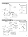 5
5
-
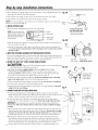 6
6
-
 7
7
-
 8
8
-
 9
9
-
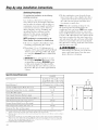 10
10
-
 11
11
-
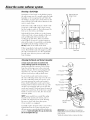 12
12
-
 13
13
-
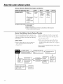 14
14
-
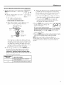 15
15
-
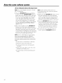 16
16
-
 17
17
-
 18
18
-
 19
19
-
 20
20
-
 21
21
-
 22
22
-
 23
23
-
 24
24
-
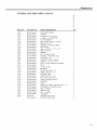 25
25
-
 26
26
-
 27
27
-
 28
28
-
 29
29
-
 30
30
-
 31
31
-
 32
32
-
 33
33
-
 34
34
-
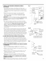 35
35
-
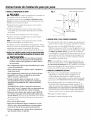 36
36
-
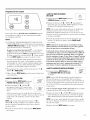 37
37
-
 38
38
-
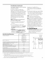 39
39
-
 40
40
-
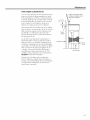 41
41
-
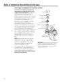 42
42
-
 43
43
-
 44
44
-
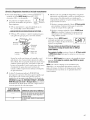 45
45
-
 46
46
-
 47
47
-
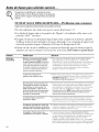 48
48
-
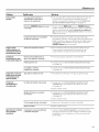 49
49
-
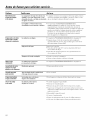 50
50
-
 51
51
-
 52
52
-
 53
53
-
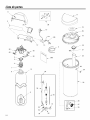 54
54
-
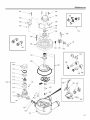 55
55
-
 56
56
-
 57
57
-
 58
58
-
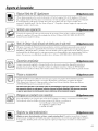 59
59
-
 60
60


En otros idiomas
- English: GE GXSF27E01 Owner's manual
Documentos relacionados
-
GE GXSF27E Manual de usuario
-
-
-
-
GE GXSH39E02 El manual del propietario
-
-
-
-
GE GXSH45V El manual del propietario
-