
vvvvw.GEAppliances.com
©
Safety Information .......... 2
Installation Instructions . ._3-1_2
Step-by-step instructions . . .6-12
Operating Instructions
Breaking a sah bridg_ ....... 14
Cleaning the nozzle and
venturi assembly ........... 14
Features .................. ] 5
Service ............. 13, 16-18
V_'ater softener system .... 1,9,-18
Care and Cleaning ........ 19
Troubleshooting Tips .... 20-22
Consumer Support
Consumer Support . .Back Cover
Parts list/catalog ........ 24-27
V_'arranty (U.S.) ............ 98
_'arrantv (Canada) ......... 99
Water
Softening
System
ModelGXSF18G
Sistema Suavizante
de Agua
Mode/o GXSF18G
La secci6n en espafiol empieza en la pagina 31
System tested and certified by NSF International
against NSF/ANSI Standard 44 for the chemical
reduction claims specified on the performance data.
Write the model and serial numbers here:
Model #
Serial #
To lind these numbers, lift the cover and
look on the rim below the control panel.
7270321 215Cl173P007 49-50140-1 12-04JR

IMPORTANTSAFETYINFORMATION.
READALLINSTRUCTIONSBEFOREUSING.
WARNING!
For your safety, the information in this manual must be followed to minimize the risk of electric shock,
property damage or personal injury.
SAFETYPRECAUtiONS
_: Check and conq)ly with vour state and local
codes. You must fl)llow ti_ese guidelines.
::Ji::Use care when handling the water sotiening
s_:stem. Do not tm'n upside down, drop, drag
or set on sharp protrusions.
_: Water sotiening systems using sodimn chloride
(salt) for recharge add sodimn to the water.
Persons on sodium restricted diets should consider
the added sodium as part of their overall intake.
Potassium chloride can be used as an alternative
to sodium chloride in your softener
Tile _sater softening system _sorks on 24 _olt,60 Hz
electrical power only. Be sure to use onlythe
included transformer
_: Use clean water softening salts only, at least
99.5% pm'e. NUGGET, PEI,I,ET or coarse
SOLAR salts are recommended. Do not tlse rock,
block, granulated or ice cream making salts.
They contain dirt and sediments, or mush and
cake, and will create maintenance problems.
::Ji::Kee I) the salt hole cover in place on the softener
tmless servicing the trait or refilling with salt.
_, WARNING:Do.o, use with water that is
microbiologically tmsat_" or el unknown quality
without adequate disinfection beti)re or atier
tile system.
iJi::Transformer must be )luo,_ed into indoor
120 "_olt, grotmded outlet only.
PROPERINSTALLAtiON
This water softening system must be properly installed and located in accordance with the Installation
Instructions before it is used.
?_: Install or store where it will not be exposed to
temperatures beh)w fl'eezing or exposed to any
type of weather: Water fl'eezing in tile system will
break it. Do not attempt to treat water over I O0°E
::Ji::O0 n0tinstall in direct s/mlight, Excessive sun or
heat may catlse distortion or other damage to
non-metallic parts.
Properly ground to cent)tin with all governing
codes and ordinances.
Use only lead-free solder and flux for all sweat-
solder connections, as required by state and
federal codes.
_: Softener resins may degrade in tile presence
of chlorine above 1 ppm. If you have chlorine
in excess of this alnount, you inay experience
reduced life of tile resin. In these conditions,
you may wish to consider pro'chasing a (;E
i)oint-ofent_y household filtration system with
a chlorine reducing filte_:
A WARNING:Disc.,d.lluilusedpax'ts
and packaging material alter installation.
Small parts remaining after the installation
could be a choke hazard.
The water softening s}:stem requires a minimmn
water flow of three galhms per minute at the inlet.
Maximum allowable inlet water pressm'e is 125 psi.
]f daytime pressure is over 80 psi, nighttime
pressm'e may exceed the maximmn. Use a pressm'e
reducing wdve to reduce the flow if necessarx:
READANDFOLLOWTHISSAFETYINFORMAtiONCAREFULLY.
SAVETHESEINSTRUCTIONS
2

Installation instructions. GEA,,,,liancescam
A_ CAUTION: Certain plumbing skills are needed for installation. If you are unsure about
any part of the installation of this product, consult a professional plumber.
Unpacking and Inspection
Be sure to check the entire softener for any
shii)ping damage or parts loss. Also note
dmnage to the shii)ping cartons. Contact the
transportation company for all damage and
loss claims. The ii/antlf;iCttli'ei" is not
responsible fl)r damages in transit.
Small parts needed to install the softener are
packaged either in a bag or on a cardboard
sheet. To avoid loss of the small parts, kee I)
them packaged until you are ready to use them.
Be StlYe not to discard components hidden in
packaging.
Important Installation Recommendations
Read entire manual. Failure to follow aft guidelines and rules could cause personal injury or
properly damage.
::Ji::Before you begin installation, read these
Installation Instructions completely. Then,
obtain all the materials and tools you will
need to make the installation. Failm'e to
properly install the softener voids the
W_I I'I'_l n IV;
Maximmn allowable inlet water pressure is
12,5 psi. If daytime pressm'e is over 80 psi,
nighttime pressm'e may exceed the
inaxilnum. Use a pressure reducing valve
if necessary. (Adding a pressm'e reducing
valve Inav reduce the flow.)
Check local codes. The installati(m must
COIl[OI'Ill 10 thenL
In the Commonwealth of Massachusetts,
Plumbing Code 248 CMR shall be adhered to.
Consult with your ficensed plumber.
Use only lead-h'ee solder and flux for all
sweat-solder connections, as required bv
state and federal codes.
(_onnect the softener to the main water
SUl)ply pipe before or ahead of the water
heater. DO NOT RUN HOT WATER THROUGH
THESOFTENER.Temi)erature at water
passing through the softener illtlSt be
less than 120°F.
::Ji::The softener works on 24 volt-60 Hz
electrical power only: Be sure to use the
included transfl)rmer. Be sure the electric
outlet and transflmner are in an inside
location to protect ]VI'OII/ ii/oisttlre.
N See Where to Install the Softenersection fi)r
more details.
A WARNING:Do.,it.sewithwater
that is microbiologically tmsafe or of
tmknown quality without adequate
disinfection before or alier the system.
The water should be tested periodically
to verifk' that the system is i)erforming
satisla ctorilv.
::Ji::Use care when handling the softener.
Do not turn upside down, drop, drag
or set on sharp protrusions.
::Ji::Small parts remaining after the installation
could be a choke hazard. Discard saflqv.

Installation instructions.
Plan How You Will Install the Softener
You must first decide how to mm in and out
pipes to the softener. I,ook at the house
main water pipe at the point where you will
connect the soiiener. Is the pipe soldered
coppe_; glued plastic or threaded galwmized?
What is the pipe size?
.4,WARNING:Use..l, le,,d.,ee
solder and flux to prevent lead poisoning.
See Yypical Installation Illustration, Fig. 1. Use
this as a guide when planning yore" particular
installation. Be sure to direct the incoming hard
water supply to the softener valve inlet fitting.
The valve is marked IN and OUT See illustration
on page 5 to help you prepare.
Where to Install the Softener
::Ji::Place the sottener as close as possible to a
sewer drain, or other acceptable drain point
or standpipe.
::Ji::It is recommended to kee I) outside thucets
on hard water to save sott water and salt.
_: Do not install the softener in a place where it
could fi'eeze. Freeze damage is not covered by
the warranty.
_: Do not install the softener where it would
block access to the water heater or access to
the main water shutott.
Put the softener in a place where water
damage is least likely to occur if a leak
develops. The manufacturer will not repair
or pay for water damage.
_: A 120 volt electric outlet is needed to plug
in the included transtormer. The sottener
has a 10 toot power cable. If the outlet is
remote (up to 100 filet), use 18 gauge wire
to connect. Be sure the electric outlet and
transformer are in an inside location, toprotect
from wet weather. Be sure the outlet is
unswit('hed to prevent accidental shutolt.
_: If installing in an outside location, you must
take the steps necessary to assure the sotiene_;
installation plumbing, wiring, etc., are as
well protecmd ti'om the elements (stmlight,
rain, wind, heat, cold), contamination,
wmdalism, etc., as when installed indoors.
Outdoor installation is not recommended and
voids the warranty.
_: Keep the softener out of direct sunlight.
The sun's heat may distort non-metallic
parts and may damage the electronics.
Toolsand Materials Required for Installation
_: In and out fittings included with the softener
are 3/4" (nominal) Col)per sweat tubes.
You should maintain the same, or larger,
pipe size as the water supply pipe, up to the
sottener inlet and outlet.
Use the included bypass wdve to install the
sottener. The bypass valve allows you to mrn
off water to the sottener fin" servicing, but
still have water in the house pipes. The in
and out fittings referred to above connect to
the bypass valve with the included nuts and
wash ers.
::Ji::Use coppex; brass or galwmized pipe and
fittings. Some codes may also allow CPVC
plastic pipes.
If additi(mal drain hose is needed tot wove
and salt tank drains, it can be ordered from
GE Parts at 800.626.2002.
::Ji::If a rigid wdve drain is needed to comply
with plmnbing codes, you can buy the parts
needed to connect a 1/2" copper tubing or
plastic pipe drain.
::Ji::Clean nugget or pellet water sottener salt is
needed to fill the brine tank, see Step 8 in
the Step-by-Step Installation Instructions.
4

GEAppliances.com
Typical Installation Illustration
MAIN
Softwater
120-voltoutlet
24V transformer
Salthole
cover
Drain
(notshown)
V47_f_P/RE
- Hardwater
_a_ddwa_e_t°ts
_ Union(notsupplied)(2)
_ Installationnut(2)
_ oppertube,3/4" (2)
Washer(2)
INLET
_assValve
• Pullout for softwater service
• Pushin forbypass
NOTE:Fittingssuppliedarefor
3/4" copperplumbing.Ifyouhave
1" plumbing,do notusethe coppertubes
andnutsincluded.Buy1" NPTfemale
adaptersandconnectdirectlytothe
1" NPTmalethreadsofthe bypassvalve.
NOTE:SeeDrain Hose Connections section.
Fig. 1 CROSSOVER
Useif watersupplyflows fromthe left.
Includesingleor3-valvebypass.
Hard water
Softwater
From softener,
)utlet
,_ To softener
inlet
Optional 3-Valve Bypass Installation Illustration
Adapters forthis installation are not supplied with the softener.Toordertheseadapters,call GEParts800.626.2000.(Askfor Part#WS60X100O6.)
24V
transf,
Salt h(
cover
Softwater "_---_N
Bypassvalve
/
Outletvalve
120-volt outlet
Drain
D ii__
Drlneweu-.J_ 7
4 P/pE
Inlet valve
d
Hardwaterto
outsidefaucets
3-Valve BypassSystem
Forsoft waterservice:
• Openthe inlet and
outletvalves
• Closethe bypassvalve
Forbypasshardwater:
• Closethe inletand
outletvalves
• Openthe bypassvalve
(2)
Coppertube,3/4"(2)
Washer(2)
Installation adapter (2) (see above)
NOTE:Fittingssuppliedarefor
3/4" copperplumbing.Ifyouhave
1" plumbing,donot usethe coppertubes
andnutsincluded.Buy1" NPTfemale
adaptersandconnectdirectlytothe
1" NPTmalethreadsof the adapters.
Fig. 2 CROSSOVER
Useif watersupplyflows fromthe left.
Includesingleor3-valvebypass.
"___-__::_-_--_:-:_:::___
Hardwater
(_ Softwater
C 9
Fromsoftener t _, Tosoftener
outlet inlet
d
5

Step-by-step installation instructions.
::Ji::Turn off the gas or electric supply to the water heater) in the possibility
that the water heater may be drained while draining pipes.
::Ji::Turn off the water supply to pipes to be cut and drain the house
water pipes.
_: Open both hot and cold taucets at the lowest location possible.
NOTE: For easier installation, remove the top cover (Fig. 3A). Slide the salt
hole cover open. i,ocate the top cover release point. Pull gently on the top
cover at the release point, lilt up and rotate top cover backwards to remove.
::Ji::Remove all packing material located under top cover.
1.INSTALL BYPASS VALVE
* Remove plastic shii_ping plug and wire ti'om valve outlet.
NOTE:Besuretheturbineand " " bv__
supportarefirralyin placeinthe __1 _u£1 utlet
valveoutlet. Blowinto thevalve _TaUn_lsn:p Sp_/
port andobservethe turbine
for freerotation, t
• Push the byl)ass valve (lubricate o-ring seals with silicone grease)
into both ports of the valve as shown in Fig. 3B.
• Snap the 2 large plastic clips in place, from the top, down as shown
in Figures 3B and 3(:. Be sure they snap into place. Pull on the
bypass valve to make sure it is held securely in place.
2. MOVE THE SOFTENERASSEMBLY INTO INSTALLATION POSITION
Be sure the installation surtace is level and smooth. Shaq_ objects
under the tank may i)uncture it. If needed, place the tank on a section
of 3/4" thick (minimum) plywood. Then, place shims under the
plywood as needed to level the sottener.
3. PLUMB "IN" AND "OUT" PIPES TOAND FROM SOFTENER
CAUTION:(-)bser\e all of the following cautions as you
connect inlet and outlet i)lumbing. See illustrations on page 5.
• BE SURE INCOMING HARD WATER SUPPI,Y IS DIRECTED TO THE
SOFTENER VAI,VE INLET PORT. If house water flow is fi'om the left,
use a I)lumbing crossover as shown in Fig. 1, page 5. If the house water
flows up from the floor level, turn the bypass valve upside down as shown
in Fig. 3D,
" If making a soldered copper installation, do all sweat soldering before
comlecting pipes to the bypass valve, Torch heat will damage i)lastic
parts.
• When turning threaded pipe fittings onto plastic fittings, use care not
to cross-thread,
" Use pipe joint compound on all external pipe threads.
• Sul)port inlet and outlet I)hunbing, in some manner (use pipe hangers)
to keep the weight off of the valve fittings.
Rg3A
TopCover_
Release
Point
Salt Hole
Cover
EmTop Cover
Rg3B
DrainFitting!
_ _'._<-i Clip
Inl
J IBypass
O-ring sealgoesinto valve
the outergrooveonly.
Theclipsnapsinto the
innergroove(seebelow).
Fig. 3C
SIDE
VIEW
Clip
END
Valve body Bypassvalve
inlet or outlet (push all the way in)
Rg3B
Turnbypassvalve
upsidedownto
O_U connectto floor
levelplumbing
T
IN

4. CONNECTAND RUN THE VALVEDRAIN HOSE
• Use the provided drain hose (20' length included) to attach to the
valve drain fitting. To kee I) water pressure fl'om blowing the hose off,
use a hose clamp to secure in place. Cut the necessary length and use
the remainder in Step 5.
• i,ocate the other end of the hose at a suitable drain point (floor drain,
sump, latm(h T tub, etc.) that terminates at the sewer. Check and comply
with local codes.
IMPORTANT" If more drain hose is needed, it should be ordered fl'om
GE Parts at 800,626,2002, The water softener will not work if water
cmmot exit this hose during recharge,
• Tie or wire the hose in place at the drain point. High water pressure will
cause it to whip during the back-wash and tast rinse cycles of recharge.
Also provide ma air gap of at least P½" between the end of the hose and
the drain point. An air gap prevents possible siphoning of sewer water
into the softener, if the sewer should "back-ui)."
• Elewtting the drain hose may cause back pressure that could reduce
the brine draw during recharge. If raising the drain line overhead is
required to get to the drain point, measure the inlet water pressure to
the softener first. Fox" inlet pressures between 20 and 50 psi, do not raise
higher than 8' above the floor. Fox" inlet pressure above 50 psi, the drain
line mav be raised to a maximum height of 14'.
4ll. CONNECTING A RIGID VALVEDRAIN TUBE
To adapt a copper drain tube to the soflenel, use a hacksaw to cut the
barbed end li'om the drain fitting as shown in Fig. 4A. Rotate the drain
fitting st) the cutting blade clears the valve housing to prevent damage to
valve, guy a compression fitting (l/4" Iemale pipe thread x l/2" O.D. tube)
and needed tubing li'om your local hardware store.
5. INSTALL THE BRINE TANK OVERFLOWFITTINGS AND HOSE
• Insert the rubber grommet into the 3/4" diameter hole ix) the brine
tank sidewall as shown ix) Fig. 5.
• Push the end of the hose adapter elbow into the grommet as shown
ix) Fig. 5.
• Attach a length of hose (use remaining hose fl'om Step 4) to the hose
adapter elbow. Use a hose clamp to hold it ix) place.
• I,ocate the other end of the hose at the drain point. DO NOT ELEVATE
this hose higher than the elbow on the brine tank.
IMPORTANT"DONOT TEEOVERFLOWHOSETOVALVEDRAINHOSE.
NOTE: This drain is flxr safe U only. If the cabinet (brine tank) should
Dye>fill with water, the excess is carried to the drain.
GEAppliances.com
Fig. 4
STANDPIPE
LAUNDRYTUB
a,, ,
SUMP
/,_-_-/11/Z'air gap
Rg4A
1/4" NPTthreads
_,_.. _V/ Barbs
Cli_q i
Cut barbs
from drain
fitting
1/U O.D.
coppertube
(notfurnished)
Compressionfitting,
1/4" NPTX 1/2" O.D.tube
(notfurnished)
Rg5
/, -.i,osec,amp
Grommet I I _
_/ uo no_connect to
/k va_ drain b°se
To sewer drain
7

Step-by-step installation instructions.
6. INSTALL GROUNDING CLAMP
A DANGER:F ,il.,et,,i,,,,pe,1, ,tt .h
clamI) could result in electrical shock.
If phunbing is metal, to maintain electrical ground
continuity in the house cold water piping, install the
included ground clamps as shown in Eg. 6.
" Clean pipe with emery paper in the area where the
clamp is to be installed.
" Install grounding clamps as shown, making stu'e
ground clamps fit fl'eelv around pipe.
• Make sure lock washer is in place.
• Handtighten scrm_, then one more fifll tm'n with
screwdriver.
NOTE: When replacing an existing softene,; also replace
grounding clamps.
If removing softener completel 5 hard-i)lumb the water
line with same type of pipes as the original to assure
phmg)ing integrity and ground continuity over the life
of the h om e.
7.RUSH PIPES, EXPELAIR FROM SOFTENERAND
TEST YOURINSTALLATION FORWATERLEAKS
A CA UT#ON: To avoid water or aJr pressure
dmnage to softener inner parts, be sure to do the
following steps in exact order.
• Fully open 2 cold soft water faucets nearby the softener.
• Place bypass valve in "bypass" position by pushing the
stem inward.
" Fully open the house main water pipe shutoff valve.
Observe a steady flow from both faucets opened in
the step above.
• Place bypass valve in the "service" position EXACTLY
as follows. I_:l):P SOl)q" WATER FAUCETS OPEN.
SLOWLY pull or slide the valve stem (out) toward the
service position, pausing several times to allow the
softener to pressurize slowly.
• After about 3 minutes, open a HOT water faucet
for 1 minute, or until all air is expelled, then close.
NOTE: If water appears chmdv or has salty taste,
allow to I/ln foI" several iuoYe minutes, or tmtil clear.
• Close all water faucets.
• Check your plumbing work for leaks m_d fix fight
away if may axe found. Be sure to observe previous
caution notes.
• Turn on the gas or electric supply to the water heater.
Light the pilot, if applicable.
Rg6
Tovalveinlet
G_ound_Z
Fr0mvalveoutlet
8.ADD WATERAND SALT TOTHE BRINE TANK
" Reinstall top cover assembly, align cover with the top
of the softener. Push down to snap cove," into place.
Open the salt hole cove," and squeeze the top cove,"
and the blue rim together near the top cover release
point (Fig. 3A) to completely assemble the top cover
to the rim.
" Slide open the salt hole cove,'. Add about 3 gallons of
water into the tank. Do not add into the brinewell.
• Fill tank with NUGGET, PEI,I,ET or coarse SOLAR
water softener salt with a purity of 99.5% or higher.
Do not use rock, block, granulated and ice cream-
making salts, or salt with iron-removing additives
(except lot Diamond Crystal '_Red*Out _'_brand salt).
Maximum salt storage capacity is ai)proximately 100 lbs.
Kee I) the salt hole cover closed tmless servicing the unit
or refilling with salt.
NOTE:If the softener is installed in a lmmid basement or
other daul l) a,'ea, it is bette," to fill the tmlk with less salt,
more frequently. Sixty to 80 lbs. of salt will last tot several
months, depending on water hardness, tamily size and
water softening system model.
9. CONNECT TOELECTRICALPOWER
Remove packing material from transformer. DO NOT
P/JI,I, OR DISCONNECT WIRING.
" The softener works on 24 volt-60Hz electric power.
The included transflwmer changes standard 120-volt AC
house power to 24 volts. Plug the trmlsformer into a
120wolt outlet only. Be sure the outlet is always live so
it can not be switched off bv mistake.
8

Programmingthe Control
SALT ll_l'l_lFi I_ SALTLEVEL
L_WL i U'U U
PM PRESENTTIME
DAYS TO EMPTY
I I t I_ HARDNESS
--t C! RECHARGE
_- TIME
® ®
CONTROL SETTINGS RFQU1RED upon installation
and after an extended power outage.
NOTES:
::A::WHEN THE TRANSFORMER IS PI,UGGED INTO
THE EI,ECTRICAI, OUTI,ET, 12:00 PM (flashing),
and an arrow 1_ is displayed next to PRESENTTIME
on the taceplate decal. The blue indicator light will
also flash. Program the control as instructed below.
ff I
If LOO---is flashing, use theUP • button to set
the correct F code as tollows: F18 fin" GXSFI 8(;. If you
pass by the correct code nmnber, use the DOWN •
button. Then press the MODE button to accept the
correct model.
;,'_:A "beep" sounds while pressing buttons fl)r control
programming, One beep signals a change in the
control display, Repeated beeps mean the control
will not accept a change fi'om the button you have
pressed, and you should select another button.
iA::To program the control you will rise the UP • ,
DOWN • and MODEbuttons.
7_:Use the MODE button to scroll arrow I_ to desired
control _'ilnction.
SET PRESENT TIME OFDAY
I. Press the MODEbumm until
arrow I_ points to PRESENT
TIME.
Z Press UP • or DO'AN • button to set. The LrP button
adwmces the time; the DOWN button moves the time
in reverse.
If the present time is between noon and midnight,
be sure PM shows in the display. If the present time
is between midnight and noon, be sure AM shows in
the display.
NOTE:Each press of an UP • or DO_._N • button chanoes_
the time by one minute. Holding the button changes the
time at a rapid rate.
3. When the present time is correct, press MODE to accept.
GEAppliances.com
SET WATER HARDNESS NUMBER _,_ _
I. Press the MODE button tmtil _ HARDNESS
arrow I_" points to HARDNESS.
2. Press UP • or DO'AN • button
to set wmr water hardness number in the display. DOWN
decreases the hardness value. ILrP increases the hardness
vahle.
NOTE:Each press of a button changes the display by 1,
between 1 and 25. Above 25, the display changes 5 at a time
(25, 30, 35, etc.). Holding a button in changes the nulnbei_
at a rapid rate.
3. When the display shows yore" water hardness (in grains
per galhm), press MODE to accept.
NOTE:If there is clear water iron in your water supply,
you will need to increase the hardness setting by 5 for
each 1 ppm of clear water iron in your water supply.
You cml get the grains per gallon (gpg) hardness of your
water supply from a water analysis laboratory. If you are
on a municipal supply, call your local water department.
Or call Legend Technical Services, an independent
laboratory, to request a water hm'dness test kit at
1.800.826.8553, extension 47. If your report shows
hardness in paaets per million (ppm) or milligrams per liter
(mg/1), simply divide by 17.1 to get the equivalent number
of grains per gallon.
SET RECHARGE(STARTING) TIME
I. Press the MODEbumm until
arrow _ points to RECHARGE
TIME.
AM
.... -i,nn
..... C'U U
I_ RECHARGE
TIME
NOTE:A flashing 2:00 AM (factory defimlt) should show in
the display. This is a good time for recharge to start (rakes
about 2 hours) in Inost households because water is not
in use. HARD _._;__TER is bypassed to house fimcets during
recharge.
If no chm_ge is needed, go to step 3. To change the
recharge starting time, ti)llow step 2.
2. Press UP • or DO'AN • button to set the desired
recharge start time, Be sure to observe the AM or PM
as you did when setting the time of day.
NOTE:Each press of a button changes the time bv 1 hour.
Holding the buttons in changes the time at a rapid rate.
3.Press the MODE button to accept.

Step-by-step installation instructions.
Programming the Control (cont.)
SET SALTLEVEL _ _j]
I. Press the MODE button until
arrow I_ points to SALT LEVEL.
_] SALT LEVEL
2. Determine level of salt in brine tank using yellow
indicator on side of brine well, inside bcine tank
(see illustration on page 5).
3. Press UP • or DOX4N • .... I ] _" I_ SALTLEVEL
..... -C'I
button to set the SALT LEVEL
to correspond to lexel on
yellow indicator in brine tank.
NOTE:Each press of a button changes tile level bv
increments of 0.5 up to 8.0. (The GXSFI 8 salt level
maxim um is 5. Setting the control over 5 will result in the
unit running out of salt befi)re low salt indicator comes on.)
As the number increases, the salt level bax_ increase on
each whole number. I,owering the salt level below zero
tHx'xls tile SALTLEVELindicator OFE
4. Press tile MODEbutton to accept. _%_ 2" r'l
Tile displa) shows tile present time of _,_o_U
;'7
day and DAYSTOEMPTY.RECHARGE _
TONIGHTmayappear it unit is new. _ ...............
DAYS TOEMPTY _-_._nl
u [
Tile words DAYSTOEMPTYand a number - -
[
are shown in tile lower half of tile display. /
This information is shown in the normal
/
mn displa> This is to intorm the user of the xluxnbex"of days
betore the salt level in the brine tank reaches I,evel 0.
There will be salt lett in the salt tank, but it mav not be
sutticient to flflly recharge the system. Salt should be added
at this time to avoid hard water. The wflue is updated daily
and whenever tile SALTLEVELwflue is changed.
NOTE: Fox" the first several weeks of operation, the DAYS TO
EMPTY may provide erratic operation. Fox" example, tile
blue indicator light may flash, showing that more salt is
required, when the actual salt level in the tank is well above
the I,evel 0. In some cases, the DAYS TO EMPTYmav even
increase over a several week period.
It takes a couple of months for the water softener to learn
y0ur water usage pattern. Once it does this, it will accurately
determine actual salt usage pattern. During this period,
check salt level when blue indicator light flashes. If the salt
level in the tank is at I,evel 1 or above, allow system to xun.
Be sure to reset w)ur salt level indicator each time you add
salt to the system.
10

Optional Control Settings
The controller display has sexeral options and teatures.
LOW SALT ALARM I?__&_
The LOW SALTALARM, when enabled, _ nwill somM the beeper when the DAYS _ 4_)1 LIm
TO EMPTYxalue is 15 da_s or less, To
chanoe,_ this setting,, press and hold the MODEbutton for
3 seconds. ON (e_ctorv default) or OFF will flash in the
display., Press the UP _ or DOX4N • buttons to togole,
this feature ON or OFF. Press the MODE button to accept,
aim the displa)will n/oxe to SALT EFFICIENCY.
SALT EFFICIENCY SALT
.EVEL
_4hen the SALT EFFICIENCY feamre n
is ON, the refit will operate at a salt __ LII-I__
efficiency of at least 4000 grains of
hardness remoxed per p(mnd of salt. This mode of
operation is the most efficient setting for salt usa ,e
because the s_steln will tend to recharge, more often,
with less salt usa._,e Turning, the feature OFF will tend
to lengthen the time between recharge c) cles, which will
proxide the most eiticient usage of water, but may use
more salt. The degree of difference between these
two c_cles is highly dependent on the water usage and
hardness at a particular installation.
If you haxe xer_ hard water and you find your s_stem
is reoenerating exerv 1-2 days turn the SALTEFFICIENCY
to OFF to lengthen the time between regenerations.
NOTE: California Regulations require tiffs feature to be
(-)N for installations in Califl)rnia.
To chanoe_....the setting, press tl_e LIP • or D(A_N •
buttons to toggle the feature ON or OFF. Press the
MODE button to accept. The displa)will moxe to
SYSTEM/ELECTRONIC DIAGNOSTICS.
SYSTEM/ELECTRONICDIAGNOSTICS
This display contains s):stem
diagnostics inflmnation to assist in
troubleshooting problems with the
system. See pages 15-18 fl)r details.
Press the MODEbutton to return to
the normal mn display.
SALT
.EVaL
n n
u u
nnn
uuu
GEAppliances.com
LOST TIME SIGNAL
If time is lost on the displa) due to power interruption, the
blue indicator light will flash 4 times exer_ second, tmtil the
present time of day is entered.
LOW SALT SIGNAL
When the DAYS TO EMPTY drops to 15, the blue indicator
light and DAYS TOEMPTYin the display will flash every
second and the alarm will beep every 30 seconds (fl'om
8:00 AM to 8:00 PM), to notitV the user that the refit is
_mining low on salt. As soon as any button is pressed,
the alam/will stop beeping. The blue indicator light and
DAYS TOEMPTYwill continue to flash. Once salt is added
to the brine tank and the SALTLEVEL is reset, the DAYSTO
EMPTYwill be reset.
ERRORSIGNALS
If there is an error code detected, the I
blue indicator light will flash 4 times I
every second, the display will flash Err
and the alarm will beep every 30 seconds (from 8:00 AM
to 8:00 PM), to signal that the sottener requires service.
The alarm can be turned off by pressing any button, but
the blue indicator light and display will continue to flash.
See page 16 tot inflmnation to assist in troubleshooting
error codes. Once the problem is corrected, disconnect the
transfl)rmer fl'om the wall outlet momentaril B and I)lug it
back in. The normal display will appear. The motor may
um for several minutes, as the unit resets. If the problem is
not corrected, the error code will real)pear in 6 minutes.
BLUE INDICATOR LIGHT
Steady blue light indicates that the unit is working
correctly. The light flashes when the unit needs attention
from the user.
• i,ight flashes and DAYS TO EMPTYflashes--check salt lexel
and add salt as required.
" I,ight flashes and Err is in the displa)--electrical problem
with system--see page 16.
• I,ight will also flash when power to the unit has been
interrupted. Check the PRESENTTIMEsetting.
11

Step-by-step installation instructions.
Sanitizing Procedures
Tocomplete the installation, do the following
sanitizing procedures.
(}are is taken at the tactorv to kee I) your
water sotiener clean and sanitary: Materials
used to make the sotiener will not infect or
contaminate vour water supply and will not
cause bacteria to tOI'Ill OI" gI'oW. However,
during shipping, storage, installing and
operating, bacteria could get into the
softeuer. For this reason, sanitizing as
tollows is suggested when installing.
NOTE: Smfitizing is recommended by the
Water Quality Association for disinfecting.
I. Be sm'e to complete all installation steps,
including programming the control.
2. Pour about 3/4 oz. (l ½ tablespoons) of
comlnoi_ 5.25% unscented household bleach
(Clorox, I,inco, Be Peel), White Sail, Eagle,
etc.) into the brinewell. Refer to ilhlstration
on page 5.
3. IMPORTANT" Press and hold tor 3 seconds
the faceplate RECHARGE @ button to start
an ilnlnediate recharge. RECHARGEbegins
to flash in the display. The bleach will be
drawn through the water softener and ()tit
the drain. This process takes approximately
2 hours.
4[. If, after sanitization, water fl'om the house
fimcet tastes salty or has a slight cohm this is
a preservative fl'om the resin tank. Turn on
the cold sott water fimcets and drain fl)r a
ti_w minutes or until clear.
NOTE:When the above sanitizing regeneration
is over, all remaining bleach is flushed ti'om the
conditioner and veto" house COLDwater supply
is flfllv soft im m ediatel> However, yam" water
heater is filled with hard water and as hot water
is used, all remaining bleach is flushed fl'om
the system and it will refill with soft water.
When all the hard water is replaced in the
water heater, hot only and mixed hot and cold
water will be fitly soil If you want totally salt
water ilmnediately, after the above recharge,
drain the water heater until the water _tms
cold.
it WARNING:,,.t,dod,aiuthe
water heater, use extreme care as the hot
water could cause burns. Turn the water
heater off prior to draining.
Specifications/Dimensions
(;XSF18G
Rated Cat)acity* 8,000 grains with 1.8 lt)s. of sah
13,300 grains with 3.8 lt)s. of salt
18,800 grains with 10.2 lbs. of sall
Rated E/liciencv':* 4,330 grains!lb. (a; 1.8 lbs. of salt
Amomu of t ]igh Cal)acity Resin (lbs!( u./1) 33.3/0.64
Resin Tank Nominal Size (in., dia. x heighi) 10 x 21
Service Flow Rate (gt)m) 7
Water Supply Maximum Itardness (gpg) 95
\rater Supply Maximmn Clear Water Iron (t)pm)':** 5
\Vater Pressure IJmits (min.-max. t)si) **** 20-125
Pressure Drop ai Rated Service Flow (t)sig) 8
Water Teml)eratm:e I imiis (min.-max. OF) 40-120
Maximum Flow Rate to Drain (gq)m) 2.2
This system conh)rms to NSFiANSI 44 fiw the specifi( capacit_ claims as \efified and substantiated b) test data.
* _l_sting was performed using pellet grade sodium chloride as the regene_ant salt.
** E_cieney J-,_ting is valid only at the lowest sta_d salt dosage and sel_ce flow rate. This softener was e_cien(_
rated according to NSF/-\NSI 44.
_'_"*: Extent of il'On I'('I//<)_dll may \_i with Cl)llditiln/s. The (xlpil£il_ to I'('(//l((' cleal water illln iS stlbstm/tiated I)_
independent labmatol T test data. [se of Diamond Cr}staF' Red-Out' el Supra hen Out will improve iron
remm_ll. Refer to Cleaning Iron Out of the Water Softening Syeten7 section.
***"*' Canada wo_&ing pressme limits: 1.4-7.0 kg/(m _.
12

About the water softener system. GEAppliances.com
Service
When the water softening s):stem is providing
sott water, it is called "Service." During service,
hard water flows fron_ the house main water
pipe into the water sotiening system. Inside the
water sottening system resin tank is a bed made
up of thousands of tiny; plastic resin beads. As
hard water passes through the bed, each bead
attracts and holds the hard minerals. This is
called ion-exchanging. ]t is much like a magnet
attracting and holding metals. X_hter without
hard minerals (soft water) flows from the water
softening system and to the house pipes.
_Mter a period of time, the resin beads become
coated with hard minerals and they have to be
cleaned. This cleaning is called recharge.
Recharge is started at 2:00 AM (tactory setting)
by the water softening system control, and
consists of five stages or cycles. These are
FILL, BRINING, BRINE RINSE BACKWASH and
FAST RINSE,
Automatic Hard Water Bypass During Recharge
For emexgency needs, hard water is awfilable
to the home dm'ing the recharge cycles.
However,youshouldavoidusingHOTwater
becausethe waterheater will fill with the
hardwater.
Fill
Salt dissolved in water is called brine. Brine is
needed to clean the hard minerals fl'om resin
beads. To make the brine, water flows into the
salt storage area during the fill stage.
Brining
Dm'ing brining, brine travels from the salt
storage area into the resin tank. Brine is the
cleaning agent needed to remove hard minerals
fl'om the resin beads. The hard minerals and
brine are discharged to the drain.
The nozzle and venturi create a suction to
move the brine, maintaining a very slow rate
to get the best resin cleaning with the least salt.
Brine Rinse
After a pre-measured amount of brine is used,
the brine wdve closes. Water continues to flow
in the same path as dm'ing brining, except fin.
the discontinued brine flow. Hard minerals and
brine flush fl'om the resin tank to the drain.
Backwash
During backwash, water travels up through
the resin tank at a tast flow rate, flushing
accumulated iron, dirt and sediments fl'om
the resin bed and to the drain.
Fast Rinse
Backwash is followed by a last flow of water
downthrough the resin tank. The last flow
flushes brine fl'om the bottom of the tank,
and packs the resin bed.
_Mter thst rinse, the water sottening system
rettlrns to sott water selwice.
13

About the water softener system.
Breaking a Salt Bridge
Sometimes, a hard crest or salt bridge fl_rms in
the salt storage area. It is usually caused by high
humidity or the wrong kind of salt. When the
salt bridges, an empty space torms between tile
water and salt. Then salt will not dissolve in the
water to make brine.
If tile brine tank is full of salt, it is hard to tell
if wm have a salt bridge. Salt is loose on top,
but the bridge is under it. The following is the
best way to check tot a salt bridge.
Salt should be loose all the way to the bottom
of tile tank. Take a broom handle or like tool,
and carefully push it down into the salt,
working it up and down. If tile tool strikes
a hard object (be S/lYe it's not tile bottom or
sides of the tank), it's most likely a salt bridge.
Careflfllv break the bridge with the tool.
Do notpound on tile walls of tile tank.
If the wrong kind of salt made the bridge, take
it out. Then fill the tank with nugget or pellet
salt only: In humid areas, it is best to fill with
less salt, more often to prevent a salt bridge
fl'om limning.
Pencil
mark
Broom
handle
Pushtool into salt
bridge to break
Waterlevel
It
-Salt
bridge
14
Cleaning the Nozzle and VenturiAssembly
A clean nozzle and venturi is needed for the
water softening system to work properly. This
small trait makes tile suction to move brine
fl'om tile salt storage area to tile resin tank
dm'ing recharge. If it becomes plugged with
sand, dirt, etc., tile water softening system
will not work and you will get hard water.
To get to tile nozzle and venmri, remove
tile water softening system top cover. Be sm'e
the water softening system is in service cycle
(no water i)ressure at nozzle and venturi).
Then, while holding the nozzle and ventm'i
housing with one hand, renlove tile cap. i,ifl
out tile screen sui)port and screen, then tile
nozzle and venturi. Wash and rinse tile parts in
warm water tmtil clean. If needed, use a small
b_ush to remove iron or dirt. Also check and
clean the gasket.
NOTE: Some models have a small flow plug
located in tile nozzle and venmri, and/or
a small cone shaped screen in tile housing.
Be sm'e to check and clean these parts,
if vo m" model is so eq uiI)ped.
Careflflly replace all parts in tile correct order.
I,ightly lubricate the o-ring seal with clean
silicone grease or petroleum .jelly and place in
position. Install and tighten the cap, by hand only.
Do not overtighten the cap.
Cap
!
Nozzle& Venturi
housing
i;
IMPORTANT:Besuresmallholesinthe gasketare
centereddirectlyoverthe smallholesin the nozzleand
venturihousing.
*Install with numberedsideup,concavesidedown.

Normal Operation, Control Displays
During nol'n/al operation, tile present tilne of
dav and AM or PM and DAYS TO EMPTYshow
in tile control display area. _'hen tile denland
conlputer detel'lnines a l'echarge is needed,
RECHARGE TONlGHTbegins to flash in tile
display along with the present tinle. RECHARGE
TONIGHTflashes until the next l'echarge start
tinle; then changes to RECHARGE, which flashes
until the l'echarge is over.
GEAppliances.com
Feature: Optional Recharge Controls
Sonletinles, a nlanually started recharge nlav
be desired ()r needed. Two examples:
_: YOII have tlsed illOi'e water than tlStlal
(house guests, extra washing, etc.) and
VO/1 Ill_ly I'/In ()/It of soti water l)etk)l'e tile
next recharge.
::Ji::Tile svsteln ran out of salt.
Use one of tile t011owing teatul'es to start
a recharge inunediatel> or at the next preset
recharge start tinle.
RECHARGETONIGHT
Touch (do not hold) tile RECHARGE @ button.
RECHARGE TONlGHT flashes in the control
display area. A recharge will occur at tile next
preset rechalge start tilne. If vou dedde to
cancel this rechar ,e touch tl'm sanle button
()lice I/lOI'e.
RECHARGE
Press and hold tile RECHARGE @ button until
RECHARGEstarts to flash in tile control display
area. Tile water softening s):_tenl begins an
innnediate recharge and, when over in about
two hours, you will have a new supply of soft
water. Once started, you cannot cancel this
rechalge.
Feature: Memory
If electrical power to tile water softening systenl
is interlupted, tile control display is blank, and
tile bhle indicator light is off; but tile control
keeps correct tilne fin" about 6 hours. _'hen
power is restored, you have to reset tile present
tilne only if the display and bhle indicator light
are flashing. All other settings are nlaintained
and never require resetting unless a change
is desired.
If tile tilne is flashing after a long power outage,
tile water softening systeln continues to work
as it should to provide you with soft watel:
However, recharge nlav occur at tile wrong tilne
of day until you reset tile control to tile correct
tinl e of (lay
Feature/Service: Automatic Electronic Diagnostics
Tile control colnputer has a sell=diagnostic
fluIction for tile electrical svsteln (except
input power and water ii/eter). Tile conlputer
nlonitors tile electronic conlponents and
circuits fin" correct operation. If a lnalfllnction
OCC/IIN_ [lIl eITOI" code [Ippe[lI'S in tile
control display.
Tile chart on Error Codes shows tile error codes
that could appear and possible reasons for each
code. See Manually Initiated Electronic Diagnostics
to tilrther isolate tile defi_ct.
15

About the water softener system.
Service: Electronic Demand TimeFeatures and Service
ERRORCODE
DISPLAYED ERR03 ERR04 ERR05
POSSIBLEDEFECT • Control
ERR01
• Motor
inoperative
• Wiring
harnessor
connection
to switch
• Position
switch
• Control
ERR02
• Position
switch
• Control
• Motor
inoperative
or wiring
harness
• Control
• Position
switch or
wiring
harness
• Control
Toremoveanerrorcode: I. Unplugtransformer.
Z Correctdefect.
3.Plugtransformerin.
4. Waitforat least 6minutes.Theerror code will returnif thereasonfor
the error codewas not corrected.
Service: Timer/Softener, Service Checkout Procedure
If you are not getting soft water; and an error
code is not displayed, use the procedures below
to find the problen_, First make the fi)llowing
visual checks,
VISUALCHECKS:
I. Is there electrical power to the outlet the
water sottening system transfi)_ner is
plugged into?
2. Is there sufficient salt in the storage tank?
3. Is the sottener bypass wflve directing water
tor soti water service?
4 Is the valve drain hose open to the drain,
not illoi'e than S' above the sottenei', }111(1
unobstructed? If hose is above 8', see page 7,
section 4.
If you do not find a problem with the visual checks,
continue below
CONTROLSHOWS I Electricalpowerwasoff.
WRONGTIMEANDDAY, _ Resetthecorrecttimeof
AND/ORSFLASHNG. day.
Checkelectrical _-_C NOPOWER].__ REPAIRAS
CONTROL_ powerto control [ NEEDED
DISPLAY (outlet,transformer, I POWEROKI.__ [ CONTROL
BLANK. powercable,all
connections). I DEFECTIVE
Domanual
diagnostics.
CONTROLDISPLAYSHOWSI
CORRECTTIMEANDDAY -_
AND SSTEADY
I
Investigatereasonfor I
powerloss.
I
Domanual
diagnosticsto
verifyproper
I functon.
16

GEAppliances.com
Service: Manually Initiated Electronics Diagnostics
I. To enter diagnostics, press and hold ._%_
tile MODEbutton for 3 seconds until
tile LOWSALTALARMscreell shows. _/)) 0 I-!
ZPresstheMODEbutton2tin_esto _ n O]
advance throu,,h LOWSALTALARM 0
and SALTEFFICIENCYoptions. See n n ["1
Programming the Control for details IJ Ij U
011 these two optiolis.
3. OPERATIONOFDIAGNOSTICS
Motor Position
Valve | .. switch
P°S't'°n "_1_. _.t!
Water meter
"Valve Position--Press tile RECHARGE @ button to
initiate a recharge cycle. Press again to manuallx index
xalxe to next position. See Service." Manually Advance
Recharge Checkfor details.
0 - Serxice
1 - I?ill
2 - Brine
3 - Backwash
4 - Fast Rinse
" Motor Operation--Two dashes will circulate armmd
when motor should be umning
• Position Switch Operation--
I-
L - Closed--\alxe rotating to next position
ul
u - Open--\alxe in position, serxice, fill, brine, etc.
• Water Meter--Indicates whether water is flowing
throuoh xalxe.
Position-_,-
switch
.Sensor
housing
Valve
outlet
pport
andshaft
- 000 indicates no water is flowing through tile valve
- Open nearbv soft water taucet
- 000 to 199 (continual) shows water is flowing. Display
repeats tor each galhm of water passing through tile
meter. Control will beep at every gallon.
- If there is no reading in tile display, with fimcet
open, check the sensor. Pull the sensor fl'om the
valve outlet port, and pass a small magnet in fl'ont
of tile sensor. Counter should index in tile display.
If counter does not index, check to make sure
harness is cmmected to board properly. If there is
a reading in tile displa)', there may be a problem
associated with tile turbine. Turn off water supply,
close the by-pass wflve, and disconnect by-pass wflve
fl'om valve body: Check tm'bine fl)r binding or
restriction due to debris. If this does not correct
the problem, tile Timer, Sensor or Tufl)ine may
require replacement.
4. Historical data about tile softener is available.
* Press and hold tile UP • button to display tile nmnber
of days this control has had electrical power applied.
e Press and hold tile DOWN • button to display the
number of recharges initiated by this control since tile
model code nulnber was entered.
5. Press tile MODE button to return to normal operation
and (lispla}.
Service: Set Model (For H) Code
I. To chan,,e_ or check model code, first press and hold tile
MODE button for 3 seconds until tile LOW SALTALARM
screeil shows.
Z Press and hold tile MODE button again
fi)r 3 seconds. A display with E OC[ at
the top will appear.
3. Press tile UP • or DOWN • buttons
to select the correct model code.
F 18-GXSF 18(,
4. Press tile MODE button ()tie time to return to nomml
operation and display. If tile model code was changed:
• tile display will go blank momentarily, then display tile
model code entered.
* tile display will then return to tile set present time
display, and tile blue indicator light will flash. Tile
control will have to be reprogrammed. See Programming
the Control
NOTE:If tile control is left in any of tile above diagnostic
displms or a flashing displa)when setting time, hardness,
etc., it will rexert back to tile normal display in 4 minutes.
17

About the water softener system.
Service: Manually Advance Recharge Check
NOTE:The control display must show a steady
time (not flashing).
I. Press the RECHARGE @ button and hold in
for three seconds. RECHARGEbegins to flash
as the water sottening system enters the fill
cycle of recharge. Remove the brinewell
cover and, using a flashlight, observe fill
water entering the brine tank. If water does
not enter tile tank, look tot an obstructed
nozzle, venturi, fill flow plug or brine tubing.
See Care and Cleaning of the Water Softener
System section.
2.After obser\ing fill, press tile RECHARGE @
button to move tile water softening s)_stem
into brining. A slow flow of water to the drain
will begin. Veritk' brine draw fl'om tile brine
tank by shining a flashlight into the brinewell
and observing a noticeable drop in the liquid
level over an extended period of time.
NOTE: Be sure a salt bridge is not preventing
water fl'om contacting salt. See Care and
cleaning of the water softening system section.
ff the water softening system does not draw brine,
check:
i_i' nozzle and/or venttlri dirty or deti_ctive.
N defective nozzle and venturi seal.
_: nozzle and venturi not seated propedy
on gasket.
_: other inner wive defect (rotor seal, rotor
and disc, wave washe_; etc.).
::Ji::restricted drain (check drain fitting and
hose).
NOTE:If water system pressure is low, an
elew_ted drain hose may cause back pressure,
stopping brine draw.
3.Again, press tile RECHARGE @ button to moxe
the water sottening system into backwash.
I,ook for a fast flow of water fl'om tile drain
hose. A slow flow indicates a i)lugged top
distributor, backwash flow plug or drain hose.
4. Press tile RECHARGE@ button to Inove tile
water sottening s):stem into tast rinse. Again
look for a tast drain flow. Allow the water
sottening system to rinse for a few minutes
to flush out any brine that mav remain in
the resin tank fl'om the brining cycle test.
5. To return tile water sottening system to
set\ice, press tile RECHARGE @ button.
18

Care and cleaning of the water softening system. CEAppliancescem
Checking the Salt Storage Level and Refilfing
Brine (salt dissolved in water) is needed fi)r
each and every recharge. The water for making
brine is inetered into the salt storage area by
the water soflelfing systeln wflve and control.
However, you must keep the tank supplied
with salt.
When to refill with salt: If the blue indicator
light and DAYS TO EMPTY are flashing, there is
less than l 5 days supply of salt. Refill with salt.
In hulnid areas it is best to refill with less salt
and more often, to awfid the forming of a
salt bridge (see page 14). After adding salt,
remember to reset the SALTLEVEL in the
control (see page 10). Never allow the salt
level to drop below zero on the yellow indicator
heft)re wm refill it. Without enough salt, you
will soon have hard watei:
Use clean water softening salts only; at least
99.5% pure. NUGGET, PEI,I,ET or coarse
SOI,AR salts are recommended. Do not use rock,
block, granulated or ice cream making salts.
They contain dirt and sediments, or mush and
cake, and will create nmii_telmnce i)roblems.
A CAUTION:Waterso,teningsa,twith
iron removing additives: Some salts may have
an additive to hel I) the water softening
system handle iron in the water SUl)ply.
Although this additive may hel I) to kee I) the
water softening system resin clean, it may
also release corrosive flunes that weaken
and shorten the lifi_ of solne water soflelfing
systeln parts. (;E recolnn/ends using only
Dialnond Crystal <':Red*Out _':brand salt.
Cleaning Iron Out of the Water Softening System
Your water softening system takes hardness
minerals (calcium and magnesium) out oI
the water. Also, it can control solne (see the
Specification Guidelines section) "clear water"
iron. With clear water iron, water froln a fimcet
is clear when filet put into a glass. After 15 to
30 inilmtes, the water begins to cloud or turn
lust colored. A water soflelfing systeln will not
relnove any iron that inakes the water cloudy
or rusty as it Colnes fl'Oln the fimcet (called red
water iron). To take red water iron out of water,
or over the lllaXillltllll of clear water iI'Oll,
an iron filter or other equil)inent is needed.
GE reconm/ends using only Dialnond Crystal ')
Red*Out e_brand salts with Iron FighteI _')
additive to hel I) kee I) the resin bed clean of
clear iron. If your water supply has clear water
iron, periodic resin bed cleaning is needed.
(;E recolnlnends using Super Iron Out <°brand
resin bed cleaner to thoroughly clean vour
resin bed if your iron content is high. Clean
the bed at least every six lnonths, or more
often if iron al)pears ill the soft water between
cleanings.
IMPORTANT."It is important to mix the resin bed
cleaner with water (fi)lh)wing the malmfi_cturer's
instructions), pour it into the brinewell tube
(see page 5) and recharge the softener
in/inediatelv. Do not pour the resin bed cleaner
in with the salt, as it will not be as effective in
cleaning the resin, and can cause dalnage to
the softener if it is left in the brine tank for an
extended period due to the corrosive gases that
are fl)rmed.
19

Before you call for service...
Troubleshooting tips
Save time and money! Review the chart on following pages first
and you may not need to call for service.
NO SOFT WATER Most Common Problems:
Check the following before calling for service:
*Not enough salt--should be at least 1/3 full.
• Bypass valve in "Bypass" position knob should be in the "OUT" (service) position.
• Hardness setting too low--check hardness setting and adjust. Verify, hardness of
supply wamr fiom local wamr company, wamr rest or call tile (;E Answer Cenmr
• Salt Bridge--salt solidifies above wamr level so that brine wamr is not in contact
with salt. See tile Breaking a SaltBridge section.
Problem Possible Causes What To Do
No so#water Faucet or fixture where smnple was •
taken not plmnbed to soft water
NOTE,"Be suresampleis froma faucet
that doesnot mixsoftand hard water.
Forexample,a singlelever kitchenfaucet,
if thecoldside isplumbedtohard water.
To consei_:e salt, tile installer ma) ha\re isolated sonJe fiXttlFeS
(outside flmcets, toilets, etc.) fl'om soft wateI: From the outlet
of the water softening s):steln, trace the water flow path,
in house I)lumbing. If soft wamr is not direcmd to a fimcet
or fixtm'e where wanted, consult a i)lumber
No salt in the brine tax_k or
salt bridged
Check fl_r a salt bridge el; if the tank is erupt); refill with
recommended salt. Press (tor 3 seconds) the RECHARGE@
button to strut an immediate rechaige and restore
soft water suppl}:
Transformer unplugged at wall outlet or
power cable to softener not com_ected.
Fuse blown or circuit breaker popped
on circuit to electrical outlet.
Electrical outlet on a circuit that can
be switched off
" Check flw a loss of electrical power to the water softening
s)'stem, due to any ot these conditions and correct as needed.
With the power supply restored, observe the fi_ceplate time
display and read Programmingthe Controlsection.
NOTE: Theelectrical outlet for the softener should be continuously
live so it cannot be accidentally switched off
Mmmal bypass valve in
bypass position
" Be sure the b)])ass xalxe stem is positioned propefl}; with the
knob in tile OUT position. Observe instructions on the decal
at the end of the stem,
Valve drain hose pinched, plugged,
elevated too high or otherwise
restricted
" An} restriction in this drain hose may prexent proper
operation of the nozzle and xenturi and reduce or prexent
brine draw during recharoe
Nozzle mid venturi dirty, incorrectly
assembled or dmnaged
• Reti_r to Cleaning the Nozzle and l/enturiAssemblyinsmmtions.
With water pressure to the water softening system off, take
the nozzle assembly apart. Inspect, clean and replace as
needed. Any toreigu particle(s), scratches, nicks, etc., in the
passages can l)re\reIlt operation. Be sure holes in fl_e g_lsket are
cenmred ()\'el" holes in the housing.
2O

GEAppliances.com
Problem Possible Causes What ToDo
Waterhardsometimes Using hot water while the water • Avoid using hot water during water s()ftening system recharge
softelfing system is regenerating beca use the water heater will refill with hard watei: See
Automatic HardWaterBypassDuringRechargesection, page 13.
Control HARDNESSnumber setting
too low
• Press the MODEbutton until arrow points to HARDNESS,
Be sm'e the number shown is the same as the actual grains
per gallon hm'da_ess of your water supply. See the
Programming the Centre[section if a change ill the setting
is needed.
Grains of haJcdaaess in your water • _,\_ater hardness can change over time, espedally ill well wateI:
supply have increased To check, haxe the water tested b_ a water analysis laboratory
or call your local water del)artlnent. A(!just the HARDNESS
number setting as needed.
Water feels slippery Absence of hardness mhleraJs • This is nomml. Hardness ill water gives it the abrasive teel
alter installation of y(tu Inay have been accustomed to. The slil)l)ei T feel is the
water softening system clean feel of soft wateI:
Water softening system Water softelfing system is a • Does not use uluch salt to regenerate--rely efficient.
not using any salt "demmld" mlit
Possible salt bridge • See the About the Water Softener System section, page 14.
Possible plugged nozzle and veutttri • See the About the Water Softener System section, [)age 14.
Water is blue color Acidic water in copper plttmbh_g • Have the water tested at once.
alter water softening
system was installed
Water softening system Meter turhh_e stuck • See the Service." Manually InitiatedElectronics Diagnostics
notregenerating section for troubleshooting l)rocedures, [)age 17.
• Call fin" ser;'ice.
Sensor wire not plugged into • See the Service: Manually Initiated Electronics Diagnostics
the control section fin" troubleshooting i)rocedures, page 17.
• Call for service.
No power to refit • Check the circuit breaker or fllses.
MechmficaJ defect • Call fin" service.
Cloudiness on glassware Combhzatiou of soft water and • This is called etching and is l)ei-/nanent. To l)revent this
(automatic dishwashers) too much detergent fl'oln hapl)ening , use less detergent if you have soft watei:
Wash glassware ill the shoiXest cycle that will get tlaem clean.
Excessive/high level VaJve drain hose pinched, • Any restriction ill this drain hose ma) prevent i)rol)er
of water in brine tank plugged, elevated too high operation of the nozzle and venturi and reduce or i)revent
or otherwise restricted biJne draw duIJng recharge.
Nozzle and venturi dirty, incorrectly • See the Cleaning the Nozzle and VenturiAssemhlysecfion,
assembled or dmnaged page 14. With water i)ressure to the water softening systeln
off, take the nozzle assembly apart. Inspect, clean and
replace as needed. Ally fi)reign i)article(s), scratches, nicks,
etc., ill the passages can I)revent oi)eration. Be sure holes
ill the gasket are centered over holes ill the housing.
21

Before you call for service...
Troubleshooting -tips
Problem Possible Causes What To Do
Salty tasting or Unit not sanitized • Conq)lete the Sanitizing Procedures on page 12.
brown/yellow colored • At ('(nnl)ledon of recharge cycle (approx. '2h_,O, run water
waterafter installation ti'om timcets to purge the salty water:
Low water pressure Check pI'esstlI'e,
• Drain height 8' or less, pressure shotfld be minimum of 20 psi.
• Drain height above 8', pressure should be minimum ot 50 psi.
Restricted drain hose • Clean and reconnect hose.
• Check fin" ]6nks in drain line.
Brown/yellow Unit was idle for a period of time • Complete the Sanitizing Procedureson page 12.
colored water
Resin beads showing Cracked distributor " Call fin" se_i('e.
up in drinking water
and sink
Sounds you might hear Rmmhag water from the unit • This is IlOIIllal.
into a drain durhag rechmge
Water has air bubbles Air ha system after installation " _'_]11go away alter it runs fin" a while.
and is cloudy
Error Code on control Wiring may have worked loose " See page 1(3fin" details.
ha the control
• Unl)lug transfin3ne_:
• Remove control cove_; release clips on side.
• Check fin" loose/incorrect wiring connections to electronic
board or swit('h. Reconnect as required.
• Reassemble control cove_:
• Plug in Transfin3ne_:
• X_'ait six minutes fin" Error Code to real)pea_;
• If Error Code reappeaI_, call fin" service.
Blue light flashing
When power applied Control needs to be pmgrmnmed • See the Programming the Controlsection, page 9-10.
to the system (a power outage may have occurred)
If "DAYS TOEMPTY" Low salt level, less thma 15 days • Ell with salt.
is flashing • Reset salt level.
If "Err"in display Electrical problem with system • See page 16 fin" details.
• See l)rocedtlre above, EITOI" code oi1 control.
22

Notes.
23

Parts list. GXSF18GO1
999
4
28
11
146
29
/
33
31
32
19
38
23
24
24

GEAppliances.com
153
134 133
132
152
\
151
_/25
124 --
117
118
119
120
107_
115
/
/
121
130
144
\
143
146 147
150
25

Parts catalog.
GENERAL ELECTRIC PARTS CATALOG
REE NO. PART NO.
0003 WS35X10001
0004 WS34X10017
0005 WS07X10004
0007 WS14X10002
0008 WS14X10001
0009 WS01X10002
0010 WS32X10008
0011 WS31 X10027
0012 WS31 X10028
0013 WS21X10016
0014 WS31X10029
0016 WS26X10013
0017 WS31X10030
0018 WS33X10008
0019 WS33X10009
0020 WS31X10024
0021 WS02X10009
0022 WS32X10022
0023 WS02X10027
0024 WS32X10023
0025 WS18X10003
0026 WS22X10016
0027 WS22X10017
0028 WS35X10035
0029 WS15X10045
0030 WS35X10036
0031 WS03X10006
0032 WS15X10006
0033 WS03X10007
0034 WS03X10008
0035 WS07X10002
0036 WS07X10021
0037 WS31X10031
0038 WS02X10029
0039 WS02X10035
0055 WS28X10003
0056 WS28X10007
0101 WS02X10012
0102 WS02X10013
0103 WS21X10003
0104 WS03X10009
0105 WS02X10014
0106 WS31 X10006
0107 WS03X10010
0108 WS26X10002
0109 WS19X10010
0110 WS03X10011
G
X
S
F
1
8
G
PART DESCRIPTION (01)
O-RING SEAI, KIT 1
DECAL, FACEPI A,TE 1
HOSE, DRAIN, 20 FT. 1
DISTRIBUTOR, TOP 1
DISTRIBUTOR, BOTTOM 1
RESIN, 1 CU. FT. 1
RESIN TANK, 10 X 21 1
COVER, TOP ASM
W/ I,ENS & IABEI, 1
FACEPIATE 1
CONTROI, 1
LID EI,ECTRONIC 1
TILCNSFORMER WITH
POWER CORD 1
LID, SALT HOLE 1
VAPOR BARRIER 1
RIM 1
COVER, BRINEWELL W/ DECAL 1
NUT 1
BRINEWEI,I, W/ DECAI, 1
SCREW 1
TANK, BRINE, COMPACT 1
CIAMP, HOSE 2
ADAPTER, HOSE 1
GROMMET 1
GROUND (;1AMP KIT 1
BRINE VAI,VE ASM. 1
FLOAT, STEM 8.: GUIDE 1
CI,IP 1
VALVE BODY, BRINE 1
CI,IP 1
SCREEN 1
TLrBING ASM. 1
BRINE TUBE ASM. 1
EI,ECTRONICS 1
SPACER 1
SUPPORT I,ED 1
RETAI NEll CI,AMP 2
C i AM P 2
SCREW 1
SPACER 1
SWITCH 1
PIN, EXPANSION 1
SCREW 5
C(-)VER, VAI iVE 1
_2__VE SPRING 1
ROTOR & DISC ASM. 1
CAP, VENTURI 1
SEAl,, O-RING 1
26

GEAppliances.com
GENERAL ELECTRIC PARTS CATALOG
REE NO. PART NO.
0111 WSI 9X10005
0112 WS03X10013
0113 WS22X10036
0114 WS08X10008
0115 WS03X10015
0116 WS22X10021
0117 WS03X10017
0118 WS15X10034
0119 WS03X10018
0120 WS03X10019
0121 WS15X10010
0122 WS03X10020
0123 WS22X10022
0124 WS15X10046
0130 WS35X10005
0132 WS22X10023
0133 WS03X10032
0134 WS03X10022
0135 WS03X10023
0136 WS26X10003
0137 WS26X10004
0138 WS26X10005
0139 WS02X10015
0140 WS26X10011
0141 WS02X10016
0142 WS60X10001
0143 WS60X10002
0144 WS60X10003
0145 WS60X 10004
0146 WS28X10017
0147 WS19X10006
0150 WS03X10024
0151 WS15X10012
0152 WS03X10025
0153 WS60X 10006
0998 WS35X10042
0999 49-50140
G
X
S
F
1
8
G
PART DESCRIPTION (01)
SUPPORT SCREEN 1
SCREEN 1
FI,OW PIJUG, .15 GPM 1
GASKET & ASPIRATOR 1
CONE SCREEN 1
PIJ.JG, FILL FLOW, .30 GPM 1
FERRIJI,E NUT 1
NOZZLE/VENTLrRI BODY 1
RETAI NEll 1
SEAl,, O-RING, 1/4" X 3/8" 2
BODY, VALVE 1
SPRING 1
PI,UG, DRAIN SEA1, 1
NOZZI,E/VENTURI ASM. 1
SEAl, K/T, 3/4" 1
ADAPTER, DRAIN HOSE 1
O-RING, 5/8" X 13/1{;" 1
PI,UG, FI,OXM RINSE CONTROl, 1
CI,IP 1
CAM & GEAR 1
BEARING 1
PI,ATE, MOTOR, 3/4" 1
SCREAM #6-20 X 3/8" 2
MOTOR ASM. 1
SCREXM #6-20 X 7/8" 2
NLTT, INSTAI,I,ATION 2
TLrBE, INSTAI,I,ATION 2
WASHER 2
CI,IP 2
HARNESS WIRE, SENSOR ASS¥., 3/4" 1
TURBINE 8.:SUPPORT ASM. 1
SEM,, O-RING 1
BYPASS ASM. 1
SEAl,, O-RING 2
ADAPTER 2
INSTAI,I,ATION KIT 1
OWNER'S MANUAI, 1
27

GEWater Softening System Warranty. (For Customers in the United States)
All warranty service provided by our SmartWateF MAuthorized
Servicer Network. Toschedule service, on-line, 24 hours a day, visit
us at GEAppliances.com, or call 800.GE.CARES(800.432.2737) (U.S),
or 866.777.7627 (Canada).
Staple your receipt here.
Proof of the original purchase
date is needed to obtain service
under the warrantg
For The Period Of."
OneYear
Fromthe dateofthe
originalpurchase
ThreeYears
Fromthe dateofthe
originalpurchase
TenYears
Fromthe dateofthe
originalpurchase
We Will Replace:
Any part of the _,V_ter Softening System which fifils due to a defect in materials or workmanship.
During this full one-year warranty,GE will also provide, free ofcharge,all labor and in-home se_a'ice
to rel)lace the defective part. _M1 warranP,' service will be provided b v a (;E Smart_,V_ter _ Authorized
Service agent,
The electronic monitor, if it tifils due to a (lefect in materials or workmanship. During this three-year
limited warranty, you will be rcsponsible fin" any labor or in-home service costs.
A replacement brine tank or cabinet if either tifils due to a (letect in matedals or workmanship,
L)twing this ten-year limited warranty, you will be responsible for any labor or in-home service costs.
What Is Not Covered:
• Service trips to your home to teach you how to use
the product.
• hnproper h_stallation, delivery or maintenance.
• Failure of the product if it is abused, misused, or used for
other thin1 the intended purpose or used commercially.
• Defects that result from improper h_staUation or damage
not caused by GE.
• Liability on the part of GE under this or may other warranty
for rely indirect or consequential dmnage.
• Products that are used for commercial or industrial
applications.
• Filters, membrmles or batteries.
• Replacement of house fuses or resetting of circuit breakers.
• Dmnage to the product caused by accident, fin'e, floods or
acts of God.
• h_cidental or consequential dmnage caused by possible
defects with this appliance, its installation or repair.
• Dmnage caused after delivery.
This warranty is extended to the original purchaser and any succeeding owner for products purchased for home use
within the USA. In Alaska, the warranty excludes the cost of shipping or service calls to your home.
Some states do not allow the exclusion or limitation of incidental or consequential damages. This warranty gives you
specific legal rights, and you may also have other rights which vary from state to state. Toknow what your legal rights
are, consult your local or state consumer affairs office or your state's Attorney General THIS WARRANTY IS INTENDED
TOBE IN LIEU OFALL OTHER WARRANTIES, WHETHER EXPRESSOR IMPLIED, INCLUBIN6 THE WARRANTIES OF
MERCHANTABILITY AND FITNESS FORA PARTICULAR PURPOSE.
Warrantor: General Electric Company.Louisville, KY 40225
28

GEWater Softening System Warranty. (ForCustomersinCanada)
All warranty service provided by our Factory Service Centers or an authorized technician.
For service, call toll free 1.866.777.7627.
For The Period Of." We Will Replace:
One Year Any part of the _\'ater Softening S}'stem which fifils due to a defect in materials or workananship.
Fromthe dateofthe During this fullone-yearwarranty,GE will also provide, freeofcharge,all labor and in-home service
originalpurchase t(> replace the detective part.
Three Years Theelectronic monitor,if it tifils (hie tO a (lelect iIl inaterials or workinailshil). OtliJilg this three-year
Fromthe dateofthe limitedwarranty,y(>uwill be responsible tot any labor or in-home service costs.
originalpurchase
Ten Years A replacement brine tank or cabinet if either tifils due to a defect in materials or workananship.
Fromthe dateofthe During this ten-yearlimitedwarranty,y(>uwill be responsible tot any labor or in-home service costs.
originalpurchase
What Is Not Covered:
• Service trips to your home to teach you how to use
the product.
• hnproper installation.
If you have an installation problem, contact your dealer
or installer. You are responsible for providing adequate
electrical, exhausting and other cmmecting facilities.
• Replacement of house fuses or resetting of circuit
breakers.
• Failure of the product if it is misused, or used for other
than the intended purpose or used commercially.
• Dmnage to product caused by accident, fire, floods or
acts of God.
I WARRANTOR IS NOT RESPONSIBLE FOR CONSEQUENTIAI, DAMAGES. I
VCarrantor: (;AM(;() IN(;. [
29

Notes.
30

Informaci6n de sequridad ..... 32
Instrucciones para la
instalaci6n ............... 33-42
Instrucciones paso por paso ...36-49
Instrucciones para la operaci6n
C6mo limpiar la ensambladura
de la boquilla y el Venturi ....... 45
C6mo romper un puente de sal . . .44
Funciones ................... 46
Servicio ................ 43, 47-49
Sistema de descalcificaci6n
de agua .................. 43-49
Cuidado y limpieza ........... 50
Consejos para la soluci6n
de averias ................ 51-54
Soporte al cliente
Garantfa ..................... 62
Lista de partes/catfilogo ..... 56-59
Soporte al consumidor . ........ 63
Este sistema ha sido probado y cerfificado por la
NSF International contra el Estfindar 44 NSF / ANSI
pot la reducci6n de productos qufmicos, reclamos
especificados en la hoja de desarrol]o.
Escriba aqui el modelo It los nfimeros
de la serie:
Modelo No.
Serie No.
Para en('onti'ai" estos n(lIlleI'os_ levante
la c/ibierta v illire en el borde, debajo
del panel del control.
31

INFORMACIONIMPORTANTEDESEGURIDAD.
LEATODASLASINSTRUCCIONESANTESDELUSO.
AADVERTENCIA
Per su seguridad, se debe seguir la informaci6n en este manual con el fin de reducir el riesgo de una
descarga el#ctrica, dafios a la propiedad o dafios personales.
PRECAUCIONESDESEGURIDAD
_: Revise y ctunpla con to(los los c6digos estatales v
locales. Observe las pautas aquf presentadas.
_: Tenga cuidado al manipular el sistema de
descalcificacidn de agua. No lo voltee, deje cae_;
_IITilStI'e o coloque en prottlbei'ancias exti'eiilas.
N I,os sistemas de descaldficacidn de agua que
utilicen cloruro de sodio (sal) para la reca_ga
agregan sodio al agua. Las personas que siguen diotas
con rostricciones de sodio deben considerar el sodio
adicional come parte de su consume general. El cloruro
de potasio puede usarse come una altemativa para
el cloruro de sodio de su descalcificador.
E1 sistema de descalcificacidn de agua flmciona
solamente con 24 xoltio_60 Hz. Cercidrese de usar
exclusivamente el transformador incluido.
E1 transfi)nnador se debe conectar finicamente
a tin toii/acoi'iJente inteiJor con conexi(Sn a tieiTa
de 120 xoltios.
_: Utilice finicamente sales para descaldficaci6n
del agua, al menos con 99.5% de pureza. Se
recomiendan las sales en PEPITAS, BOI,ITAS
o SAI, GRUESA SOLAR. No utilice sales en roca,
bloque, granuladas o sales para la elaboraddn
de helados, t_stas pueden contener suciedad v
sedimentos, o pasta y masa y podrfan crear
problemas de mantenimiento.
_: Mantenga la tapa del orifido de la sal en su lugar
en el descalcificador a menos que est_ realiamdo
i/lantenii/liento o reponiendo la sal.
A ADVERTENCIA:No.soc,,,,.g,,,q,,e
sea microbioh;gicamente insegura o de calidad
desconocida sin llevar a cabo la desintecci6n
adecuada antes o despu_s del sistema.
INSTALACIONCORRECTA
Este sistema de descalcificaciOn de agua debe instalarse correctamente y colocarse de acuerdo a los
instrucciones de instalaciOn antes de su use.
_: lnstale o ahnacene donde no quede expuesto a
temperaturas pot deb@) del punto de congelaci6n
ni est(_ eN)uesto a ningfin tipo de inclemencias
atmosl_aricas. Si el agua llega a congela_se dentro
del sismma, (_ste pod6a rompe_se. No interim dar
ti'atailliento al agtla si se enctlenti'a a tlil}l
temperamra pot encima de 38 °C (100 °F).
::Ji::N0 instale expuesto a los ravos directos del sol.
EN)osiddn al sol o calor excesivos podrfan causar
distorsi6n u otros dafios alas partes no metfilicas.
::Ji::Conecte a fierra de nmnera apropiada segfin los
cddigos y ordenanzas aplicables.
::J?::Use solam ente fundente y soldadura sin plomo para
todas las cone_ones de condensaddn soldadas,
segfin los c6digos estatales y federales aplicables.
_: E1 sistema de descalcificacidn de agt_ requiere un
flt!jo de agua inhlilno de tres g;dones por minuto en
la entmda, ia presidn de entmda mfixima pennitida
es de 125 psi. Si la presidn dumnte el dia es pot
encima de 80 psi, la presidn nocturna pod6a exceder
el mfiximo. Use una v;ilvula i'eductoi_l de presidn
pare reducir el flt{jo si es necesa_io.
::Ji::i;_s _esinas de descalcificacidn pod6an deg_v_darse
ante la presencia de cloro pot encima de 1 ppm.
Si usted fiene una canfidad de cloro mayor a _sta,
quizfis expefimente una \ida menor de la resina.
En estas condiciones, es posible que quiei;i
considemr la compm de un sistema de filtmcidn
del punto de admisidn pare casas (;E con un filtro
i'edtlctoi" de cloro.
A ADVERTENCIA:De, e ,he
partes y los matexiales de embal_!je no utilizados
despug_s de la instalaci6n. Partes pequeflas
rest;rotes despug_s de la instalad6n podrfan
representar un peligro de asfixia.
LEAYSIGAESTAINFORMACIONDESEGURIDADCUIDADOSAMENTE.
GUARDEESTASINSTRUCCIONES
32

Instrucciones de instalacion. C ,,,ia.ces.com
f
--_PRECAUCION:so nocosita cierta habilidad de plomeria para la instalaci6n.
Si usted no estb seguro acerca de la instalaci6n de alguna de las partes de este producto,
consulte a un plomero profesional.
Desempacado e inspeccion
Cerci6rese de inspeccionar cmnpletan_ente el
descalcificador en busca de daflos durante el
envfo o partes que puedan haberse perdido.
Tambi0n revise en busca de dafios en la caja
de envfo. P6ngase en contacto con la compaflfa
de transporte para cualquier reclamo par daflo
o p(_rdida. E1 tabricante no es responsable par
daflos sufl'idos din'ante el trfinsito.
i,as partes pequefias necesarias para instalar
el descalcificador se encuentran en una pieza
de CaI'ton tei]iloct/n_oi]ilada o en tlna bolsa.
Para evitar la p&'dida de las partes pequeflas,
mant_ngalas en el paquete hasta que est(_
list() para usarlas. Cerci6rese de no descartar
componentes que podrfan estar escondidos
en el embalaje.
Recomendaciones importantes para la instalacion
Lea el manual completo. Ignorar los diroctricos y reglas podr[a causar Iosionos porsonales o
dafios a la propiedad.
_: Antes de comenzar la instalaci6n, lea estas
]nstltlCciones de instalaci6n ('oillpletail/ente.
I,uego, obtenga todos los materiales y
herramientas que necesita para llevar a cabo
la instalaci6n. No instalar correctanlente el
descalcificador invalida la garantfa.
::Ji::Revise los c6digos locales, i,a instalaci6n
debe cumplir tales requisitos.
_: En el estado de Massachusetts, la instalaciOn
debe ajustarse al C6digo de Plomeria 248 CMR.
Consu,te a su plomero certificado.
::Ji::Use solamente flm(lente v soldadura sin
plomo para todas las conexiones de
condensaci6n soldadas, segfin los c6digos
esmmles v federales aplicables.
::Ji::Conecte el descalcificador en la tuberfa
de suministro principal antes del
calentador de agua. NOHAGAPASAR
AGUACALIENTEA TRAVESDEL
DESCALCIFICADOR.I,a temperamra
del agua que pase a tra\'_s del
descalcificador debe set menor de
49 °C (120 °Ft.
::Ji::Tenga cuidado cuando manipule el
descalcificador. No lo coloque boca
arriba, ni lo deje caeI; ni lo arrastre,
ni lo apoye en protuberancias.
_: I,a presi6n de entrada mfixima permitida
es de 125 psi. Si la presi6n durante el dfa es
par encima de 80 psi, la presi6n nocturna
podrfa exceder el mfiximo. Use una vfilvula
reductora de presi6n para reducir el flqjo si
es necesario. (Agregar una vfilvula reductora
de presidn podrfa reducir el flqio.)
::Ji::E1 sistema de descalcificacidn flmciona
solamente con 94 voltios-60 Hz. Cercidrese
de usar exclusivamente el transformador
incluido. Cerci6rese de que el tomacorriente
el_ctrico y el transfi)rmador estfin en el
interior de un recinto para protegerlos de
la humedad.
_: Consulte la secci6n O6nde instalar el
descalcificadorpara re;is detalles.
ZLADVERTENCIA: ,tsec..
agua que sea microl)iol6gicamente
insegura o de calidad desconocida sin
llevar a cabola desinfeccidn adecuada
antes o despu_s del sistema. E1 agua debe
probarse peri6dicamente para verificar
que el sistenla se encuentra flmcionando
satistactoriamente.
::Ji::Partes pequefias restantes despu_s de la
instalacidn podrfan representar un peligro
de asfixia. Deseche con toda seguridad.
33

Instrucciones de instalacion.
Planifique la instalacion del Descalcificador
i,o prin_ero que debe decidir es c6mo instalar las
tuberfas que ei_ti'an y salen del descalcificadoi:
F!jese en la tuberfa de agua en el ptmto donde
conectaM el descalcificadoi: ;I_ mberfa estfi
soldada con cobre, pegada con plfistico, o roscada
gal\mfizada? 4Cu51 es el talnafio de la mberfa?
A ADVERTENCIA:Use solainente
flmdente y soldadura sin plolno para todas las
conexiones de condensad6n soldadas, segfin
los cddigos esmmles y tederales aplicables.
Consulte la I/ustracidn de insta/acidn normal, Fig. 1.
(rsela como tma gufa para planificar su instalacidn
particulai: Cerci6rese de dMgir el suministro de
agua dura entrante al acoplamiento de admisi6n
de la vMvula del descalcificador ia v;ilvula est_i
marcada IN (ENTRADA)y OUT(SALIDA). Consulte
la ilustracidn en la pfigina 3:5 como ayuda para la
preparaci(m.
DOnde instalar el Descalcificador
_: Coloque el descaldficador lo mils cercano
posible a un sulnidero, o a otro punto de
drenaje o cohunna de sulninistro.
::Ji::Se recolnienda que los gritbs externos se
dejen con agua (111I";Ipara asf ahorlar agua
descalcificada v sal.
::Ji::No instale el descalcificador el1 1111lugar
donde se I/ueda c(mgelai: Losda#os debidoal !;>
congelamientono esMn cobiertospor la garantia,
_: No instale el descalcificador (hmde pueda
bloquear el acceso al calentndor (le agua o el
acceso a la vfilvula de cierre principal del agua.
::Ji::Coloque el descalcificador ell un lugar donde
sea inenos probable qtle OCIIFI'a dal-lO causado
por el agua si es que eventuahnente OCUlTiese
alguna filga, E1 thbricante no reparaM ni pagaM
pot dafios ocasionados pot agua,
_: ILrn tolnacorriente de 190 w)ltios es necesario
para conectar el transfimnador que viene
incluido, E1 descaldficador tiene un cable
el(_ctrico de 10 pies. Si el tomacorriente estfi
colocado demasiado leios (hasta 100 pies),
use tm cable calibre 18 para conectado.
CerciOrese de we el tomacorriente electrico y el
transformador esMn en el interior de un recinto
para protegerlosde la humedad. Cerci6rese de
que el tolnacorlJente est0 desconectndo para
prevenir un corte el_ctrico accidental.
Si se dispone a llevar a cabo la instalacidn ell
el exterior, debe tolnar las inedidas necesarias
para asegulai_e de que el descalcificadoi; la
instalaci6n de plome6a, el cableado, etc. estfin
bien protegidos de los elementos (rayos del sol,
lhMa, viento, calm; trio), de la contan/inaddn,
\mldalismo, etc. tal v como lo estarf;m si flmran
instalados imemamente. Lainstalaci6nenel
exterior no es recomendada, y anula la garantia.
Mantenga el descalcificador alejado de los rayos
directos del sol. E1 calor del sol podrfa causar
distoI_i(m u otros daflos a las partes no
inetfilicas y podrfa hacer dafio a las partes
electrdnicas.
?4
Herramientas y materiales necesarios para la instalacion
I,os accesorios de entrada v salida incluidos
con el descalcificador son tubos de cobre de
condensacidn de 3/4" ( 1,91 cln)--nolninal.
Debe inantener un talnafio igual o inavor de
mbos que los tubos del sunfinistro del agua,
hacia la entrada v salida del descalcificadoi:
::Ji::Use la vfilvula de b)pass incluida para instalar el
descalcificadoi; i,a xfilvula de b)I)ass le pemlite !;?:
desconectar el suministro de agua hacia el
descalcificador para efl_ctuar servicio, pero afin
inantiene el agua llegando a las tuberfas de la
casa. i,os accesorios de entrada y salida a que
nos i'eJ[eiJiilos anteiJoi]//ente se conect_ln a la
vfilvula de bypass con las tuercas v arandelas ::Ji::
incluidas.
::Ji::Use accesorios y tuberfas de col)re, latdn o
galvani/;Mos. Mgunos cddigos podrfan pemfitir
el uso de mberfas pl;isticas CPVC.
_: Si tma manguera adidonal es necesaria para el
drenaje de la vfilvula y el tanque de sal, usted la
puede solicitar ell Accesorios GE llamando al
800.626.2002.
Si necesita una vfilvula rfgida de (h'em!ie para
cumplir con los c6digos de phmlerfa, podM
fiOll/pi';li" l[is partes necesalJaS p[1i';i fiOlleC[11i"
un drenaje de tuberfa de col)re o plfistico de
1/2" (1,27 cm).
Sal del descalcificador ell una pepita limpia o
bolita de agua es necesaria para llenar el tanque
de agua sahnuera, consulte las Instruccionos do
Insta/acifn Paso por Paso ell el Paso 8.

GEAppliances.com
Ilustracion de instalacion normal
Aguadescalcificada
Transformador
de24V _ _
\ Drenaje
\ (nomuestra)\Or..
Tapadel _
_ fliCi_a_/
\ ep6slto _j-2-
\aela :;_: : \
] salmuera__,}i I \
T@@f4 OE4@ 4 @tNCIPAL
__'--. Aguadura
k_
[ [ _...._ Aguadurahacia
Tomacorriente U - los grifosexternos
de 120voltios _ Uni6n(noincluida)(2)
Fig. 1 ViADEENLACE
Uselasi elflujodesuministrofluye
desdela izquierda.IncluyaunaderivaciOn
.....___ . sencillaode3 v_lvulas.
Ag
dura
Agua
descalcificada
-_ TuercadeinstalaciOn(2)
/
_Tubo decobrede3/4"(1,91 cm)(2)
I
Arandela(2)
Valvula debypass
* Tirehaciaafueraparaserviciodeagua
ENTRADA descalcificada
° Empujeparabypass
NOTA:Losaccesoriosproporcionadossonpara
plomeriadecobrede 3/4" (1,91cm).Siusted
tieneplomerfade1"(2,54 cm),nouselos
tubosdecobrey lastuercasincluidas.Compre
adaptadoreshembrasNPTde 1"(2,54cm)y
con_ctelosdirectamentealas roscasmacho
NPTde 1"(2,54cm)dela v_lvuladebypass.
fOTA:VerlasecciOnConexiones de la manguera de drenaje.
Dela
salidadel 1'
I Haciala entrada
descalcificador
deldescalcificador
Ilustracion de la instalacion opcional de una derivacion de 3 valvulas
Los adaptadores para esta instalacion no vienen incluidos con el descalcificador. Paraordenar estos adaptadores, Ilame a GEParts al
800.626.2000. (Solicite la parte # WS60X10006.)
Transformador
de 24V
Tapadel
orificiode
Aguadescalcificada,_.,._
Tomacorriente
de120voltios
Drenaje
(no
V_lvulade
bypass
V_lvulade
salida
ENTRADA
UA Aguadurahacia
PRINCIPAL losgrifosexternos
a
I I " Wlvula de
] ] entrada Sistemadederivaci6n
L_ A_/ de3v_lvulas
F Parae|serviciodeagua
descalcificada
_)F !:iiia!ic{!{iii;iias de entrada
I,I / desalida
,,Cierrelavalvuladebypass
Paracircunvalarel aguadura:
• Cierrelasvalvulasde
entradaysalida
• Abralavalvuladebypass
(2)
decobrede3/4" (1,91cm)(2)
(2)
ptadordeinstalaciOn(2)(verarriba)
NOTA:LosaccesorJosproporcionadossonpara
plomefiadecobrede 3/4"(1,91 cm).Siusted
tieneplomerfade1" (2,54cm),nouselos
tubosdecobrey lastuercasincluidas.Compre
adaptadoreshembrasNPTde1" (2,54cm)y
con_ctelosdirectamentealas roscasmacho
NPTde 1"(2,54cm)delos adaptadores.
Fig. 2 , VIADEENLACE
Uselasi el flujo desuministrofluye
desdela izquierda.Incluyaunaderivaci6n
sencillao de3v_lvulas.
Aguadura
Dela __
salidadel "7-7"1
descalcificadi¢
Agua
descalcificada
9
Haciala
entradadel
descalcificador
35

Instrucciones de instalacion paso por paso.
iJi::Suspenda el surrlii_istro tie g_Jso de energfa el_ctrica que _dimenta el c_dentador de
agua, en la posibilkiad de que el calentador pueda drenarse rnientras usted drena
]as tuberfas.
}i:)Desconecte el suministro de agua hacia los tubos que hart de ser cortados y drene las
tuberfas de agua tie la casa.
}i:)Abras ambos g31Ibs,el de agua fi'fay el de agua caliente en el lug_u"m_&bajo posible.
NOTA:Pma una instalaci6n mils fikil, mmue\a la cubierta superlol: (Fig. 3A). Deslice
la apermra la cubierta de la sa] hasta abrlrla. [z)calice el punto tie liberaci6n tie la
cubierta superlol: Tire ligeramente en In cubierta superior en el punto tie liberaci6n,
le_ante v rote la cubierta superior hacia atrfis para remoxex:
!i(:Remue',a u)do el material de empaquetado locali;'_do deb@_ de la cuNerta
st/pelJOF
1.INSTALELAVALVULADEBYPASS
• Remue_a el tap6n plfistico de embak_iey el cable de la sa]ida de la %lvula.
NOTA:Cerci6resedequela /j__._z_:_zcz_........__
turbinayel soporteseencuentren ' Turbina
firmesensusposicionesen la _ _ , ____LL Salidade la%lvula
o v vuoSo hoco
la boquilladela %lvulay observe Ejey soporte
quela turbinaseencuentra ,_ de laturbina
rotandolibremente.
• Empqje la %lvula de bH)ass (lubrique los aros tdficos con grasa de silicona) hacia
ambas boquillas de la %lvula como se muestn_ en la Fig. 3B.
• Eng',roche los dos clips plfisticos en sus posiciones, a partir de la parte superior y
hacia abajo, como se muestn_ en las Figs. 3B y 3C. Cerd6rese de engancharlos en
sus lugares apropiados. Tire de la vidvula de bypass para cerdorarse de que se
encuenlra soste_fida con seguridad en su lugar.
2.MUEVALAENSAMBLAOURAOELDESCALCIF/CADORHACIASUPOSICIONDE
INSTALACION
Cercidl_se de que la superficie de instalacidI_ se encuentre ni_elada v lisa. Cualquier
objeto col'tame debajo del tanque podrfa causar una hendidura en el mismo. Si es
necesario, coloque el tanque sobl> una seccidn de plF,vood de tin grueso mfl_imo
de 1,91 cm (3/4"). Luego, coloque cutlas deb@) del pl}_mod seg(m sea necesario
para nivelar el descalcificador
3.CONECTELASTUBERIASQUEENTRANYSALENDELDESCALCIFICADOR
& PRECAUCION: rSigd [()d_ts ];:|s prec_ltl(-ioiles si_-[lieiltes lllieI/tl'_ls
conecta la plomerfa de entrada t salida. X_a las ilustraciones en la pfigJna 35.
• CERCIORESE DE QUE EL SUMINISTRO DE AGUA DURA ESTer,
DIRECTAMENTE CONECTADO _M,PUERTO DE [A \;_d,Vt IIA DE ENTRADA
DEL DESCM_CIFICM)OR DE AGUA. Si el flujo del agua de la casa es desde la
izquierda, use un crossover de mberfa como se muestra en la Fig-ura 1, pfigina 34.
Si el flujo del agua de la casa flu}e hacia arrlba desde el nivel de piso, w)ltee la
vfilvula de bypass boca abajo como se muestn_ en la Figura 3D.
• Si se dispone a llevar a cabo una instalacidn con solda&n'a de cobre, haga todas las
soldaduras de conde_tsaci6n ames de coneetar los tubos a la vfilvula de bypass. E1
calor de antorcha dafmrfi las parms plfisdcas.
• Cuando se ellcuentre g_mndo accesorios de tuberfa roscados el/ accesorios
plfisticos, cerddrese de no cruzar las roscas.
• Use tin compuesto de jtmm de tuberfas en todas las roscas extemas.
• Apo}e la mberfa de entrada y de salida de alg-una manera (use colg_adores de
tuberfa) para evitar que el peso se deposite sobre los ajustes de las vidvulas.
RgJA
Puntode
liberaci6n
dela
cubierta
superior
Cubiertadel
agujerodela sal
Rg3B
Accesoriode
drenaje
_a _a._e-- Clip
ntrac
/ I IV_lvulade
Elsello del agotorico bypass
va ell Jamuesca
externasolamente.El
clip engrapaenla muesca
interna(verm_sadelante).
Fig. 3C
VlSTA
LATERAL
Cuerpodela
de entradaosalida
Clip
X VISTA
POSTERIOR
@
Wlvula debypass
(empujela al maximo)
Fig. 3D
€
SALIDA
ENTRADA
Girela %lvula
debypassboca
arribapara
conectara la
tuberiaal nivel
delpiso.
36

GEAppliances.com
4. CONECTEYHAGA FUNCIONARLA MANGUERA DEDRENAJE Fig. 4
DELA V,4LVULA
" Use la manguera de drenaje (se ha incluido una de 90 pies) para
adherh'la al accesorh) de drenaje de la \_ilvula. Para evitar que la presi6n
del agua expulse la manguera, use tma abrazadera de mangueras para Acces(
asegurarla ell su lugm: Corte la hmgimd necesafia y use la parte restante de drenaje
ell el Paso 5. en la %lvula
" Ubique el otro extremo de la manguera ell tmpunto apropiado
para drenar (drenaje de piso, stmfidero, tina de laxanderfa, etc.)
que temfine ell el sistema de alcantarillado. Cerci6rese de cmnplir
con los c6dJgos locales, de la
IMPORTANTE"Si necesita m_is manguera de drenaje, ord_nela llanmndo manguera
' de
al Del)artmnento de Partes de (;E al 800.626.2002.1_3 descaJcificador de
drenaje
agua no fm_ciona si el agua no escapa por esta mm_guera dttrm_te las
generaciones.
• Ate o anlarre la inanguera ell un lugar cercano al punto de drenaje.
Una alta presi6n de agua podrfa causar que el extrelno de la inanguera
se inuex i err_iticalnente dulante los ciclos de lavado reoresixo v enjuague
i'_ipido de la generacidn. TmnbiOn deje tma tolerm_cia de aJre de al
menos 3,8 on (P½") enlre el extremo de la mm_guera y el pmlto de
dxenaje. Este espacio previene que Octlrra tin electo sif6n del agua de
alcantarillado hacia el descalcificadoi; si ocurriese un ciclo de laxvl(lo
regresix o.
" Elex u" la manguera de drenaje podrfa causar tma presi6n negafixa que
podrfa reducir 1;i toma del contenido de sal durante las generaciones.
Si fllem necesario lex tatar 1;i manguera de drem!je hasta tm nixel superior
;11descalcificador para llegar hasta el punto de drem!je, nfida primero
la presi6n de entrada de agua hacia el descalcificadoi: Para las presiones
de entrada entre 20 V 50 psi, no elexe infis de 8 pies (2,67 I/l) por encin/a
del piso. Para la presi6n de entrada por encilna de 50 psi, la inanguera
de drenaje podi'fil lexantaise a una altura infixinm de 14 pies.
4,4.COMO CONECTARUN TUBODE DRENAJEDE V,[ILVULARiGIDA
Para adaptar tm tubo de drenaje de cobre al descalcificad(n; use una
sierra de arco para cortar el extremo de pfia del accesorio de drenaje,
tal v como se inuestra ell la Fig. 4A. Rote el accesorio de drenaje de flmna
tal que la h@l de corte evite el alojalniento de la xfilxtlla para prexenir
daflos a la x;ilxula. (_olnpre un accesorio de colnpresi6n (tubo helnbra Fig.5
de rosca de //_ [ ,0. cmj x 1/2" [1,97 cm] de di;imetro externo) y
los ttlbos necesaiJos ei1 Illl}l _'biTeteYla local.
5.INSTALELOSACCESORIOSDESOBREFLUJODELTANQUEDE
SALMUERA YLAMANGUERA
" lnserte una ar;mdela de goma ell el agujero de 3/4" (1,9 cm) de di;imetro
ell el lado del tanque de sahnuera colno se nnlestra ell la Fig. 5.
" Empt!je el extrelno del codo adaptador de la inanguera hacia la
ar:mdela como se muestra ell la Fig. 5.
• Adhiera la manguera (use la manguera que sobre del Paso 4) al codo
adaptador de 1;i manguera. Use una abrazadera de mangueras para
ll/antenel]a lili/lell/ente ell Stl hlgaI:
•/Jbique el otro extrelno de la inanguera ell el punto de dren_!je.
NO ELE'VE esta inanguera in,is all_i del codo ell el tanque de salnnmra.
IMPORTANTE."NOSOBREFLUYAENTLAMANGUERAHACIALAMANGUERA
DEDRENAJEDELAVALVULA.
NOTA: Este dt'en;!je es para seguridad solamente. Si el gabinete (el tanque de
sahnuera) se llena delnasiado de a ,ua el agua excesix i se llexl ;11 drenaje.
DRENAJE
DEPISO
de
_tolerancia de
)3£ cm (11A")
El#. 4,4 RoscasNPTde
1/4"(0,63cm)
,_,_k.. / ,_Leng{ietas
Clip--_l_: ia
Cortelasleng_ietas
delaccesoriode
drenaje
Accesoriodecompresi6n,tubode
1/4" (0,63cm)NPTX 1/2" (1,27cm)
de di_metroexterno(noincluido)
Tubodecobrede
1/2" (1,27cm)de
di_metroexterno
(noincluido)
Arandela
Manguera
de drenaje
de sobreflujo
Adaptador de la
manguera
Abrazadera de la
manguera
No conectar la
manguera de drenaje
a %lvula
"x
Hacia el
drenaje de la
alcantarilla
37

Instrucciones de instalacion paso por paso.
6. INSTALELASABRAZADERASDETIERRA
A PELIGRO:No adherir aproi)iadamente la
abrazadera de tierra podrfa result;u" en tma descarga
el_ctrica.
Si las tuberfas son de metal, para mm_tener conthmidad
de fierra el_ctrica en la mberfa de agua flqa, instale las
abrazaderas de tierra inchfidas como se muestra en la Fig. 6.
• Limpie la mberfa con papel de esmerilar en el _h'ea donde
la abrazadera sexfi inst;dada.
" Instale las abrazaderas de conexi6n a fierra como se
muestra, cerciorfindose que las abrazaderas @xstan
libremente ah'ededor de la tuberfa.
• Cerd6rese de que la arandela de cierre estfi en su lugar
"Apriete con sus manos el tornilhx, luego una vuelta
completa adicional con el destomillad(n:
NOTA:Cuando reemplace un descalcificador existente,
tambi_n reemplace las abrazaderas de cone_6n a fierra.
Si se dispone a remover el descaldficador completamente,
coloque tuberfas en las lfneas de agua del mismo tipo que
las tuberfas usadas originalmente para asegm'ar la integridad
de las tuberfas y contintfidad en la conexi6n a tierra a lo
largo de la vida de la casa.
Z PURGUELASTUBERIAS,SAQUEELAIRE DEL
DESCALCIFICADORYPRUEBESU INSTALACION
EN BOSQUEDADEFUGASDEAGUA
A PRECAUCION:em'a evitm" da£zos por 'a
presi6n de agua o de aJre en las paxtes h_tenlas del
descaJcificador, cerci6rese de dax los pasos sJguientes
en el mismo orden en que se presentaal.
• Abra completaanente 2 grifos de agua descalcificada
frla en grifos cercmms aJ descaJcificador.
• Abra la vfiJvula de bypass en la posicion "bypass"
empujm_do el vfistago hacia adentro.
• Abra completaanente la vfiJvula de cierre de la tuberla
del agua principal de la casa. Observe tm flujo fijo de
mnbos grifos abiertos en el paso A, mlteriormente.
• Coloque la v_Jvula de bypass en la posicion de
"servicio', en la forma EXACTA como le especificmnos
a conthmacion. MANTENGA LOS GRIFOS DE AGUA
DESCALCIFICADA ABIERTO.
LENTAM[_ITE fire o deslice el vfistago de la vfiJvula
(hacia afuera) hacia "servicio", pausmldo vaxias veces
paxa pennitir que la presurizaci6n del descaJcificador
comience lentaanente.
• Despu6s de tmos 3 minutos, abra ml grifo de agua
CAL1ENTE por 1 mhmto, o hasta que todo el aire haya
sido ex0caJdo, luego ci6rrelo. NOTA: $i parece que el agua
estfi mrbia o fiene tm sabot salado, pemfita que el sistema
fimcione pot tmos minutos mils, o hasta que se aclare.
• Cierre todos los grifos de agua.
• h_speccione en bflsqueda de fugas en la tuberla que se
acaba de llevar a cabo y repaJce hnned_ata_naente si
eneuentra algmm. Cerci6rese de observar las notas de
precaucion mlteriores.
Fig6
Haciala entrada
dela v_lvula
Abrazaderadetierra
Provenientedela salida
de la%lvula
• Conecte d sumhfislro de gas o d6ctrico hacia el calentador
de agua. Encienda el piloto si es aplicable.
8.AGREGUEAGUA YSALAL TANQUEDESALMUERA
" Reinstale la ensambladura de la cubierta superioi; alinee
la cubierta con la parte superior del descalsificador.
Empuje hacia abajo para ajustar la cubierta en su lugar.
Abra la cubierta del agujero de la sal y apriete mientras
jtmta la cubierta superior y el marco azul cerca del
ptmto de liberacidn de la cubierta superior (Fig. 3A)
para ensamblar completamente la cubierta superior
del ill_l x'co.
" Deslice hasta abfir la cubierta del agt!jero de sal. Agregue
aproximadamente 3 gahmes de agua al tanque.
No la agregue al dep6sito de sahn uex'a.
" IJene el tnxlqtxe con sal de PEPITAS, BOI,ITAS o SAI,
GRUESA SOLAR con tma pm'eaa de 99.5 % o mawn:
No use sal en roca, en bloques, gramflada, ni de helado
(para descongelar hielo), ni saJ con adJtivos que elimine
el hierro (excepto la marca Diamond CUstal ')Red*Oue')).
I,a capacidad de ahnacenamiento de sales de
aproximadamente 100 libras. Mantenga la tapa del
agt!jero de la sal en st! lugai; a no sex"qtxe se encuentre
realizando servicios de mantenimiento o llenando de sal.
NOTA: Si el descalcflicador se instala en un s6t;mo hfimedo o
en tm firea demasiado h0meda, es mejor llenaJc el taaaque con
menos saJ, y hacerlo antis frecuentemente, De 60 a 80 libras
de sal dm'arfin wu_ios meses, dependiendo de la dm'eza del
agua, el tamaflo de la fimfilia, y del modelo del sismma de
descalcNcaci6n.
9. CONECTARA LAFUENTEELECTRICA
Remueva el material de empaquetado del transfi)rmador.
NO TIRE O DESCONECTE I,OS AIAMBRES.
• E1descalcificador flmciona con suminisuo eldcuico de
24 volfios-60 Hz. E1 mmstinmador inchfido cambia de
]20 voltios AC, normal en las residencias, a 24 voltios.
Conecte el iransformador en un tomacorriente de
120 vollios solamente. Cerci6rese de que el
tomacorfienm siempre tonga suministro el_ctfico,
yque no _tva a sex desconecmdo accidenmlmenm.
38

GEAppliances.com
Programacion del control
SALT II_I'I_IFI I_ SALTLEVEL
LEVEL i U'U U
PM PRESENTTIME
DAYS TO EMPTY
II t I_ HARDNESS
--t L,_-! RECHARGE
_- TIME
® ®
Es necesario volver a AJUSTAR LOS CONTROLES despu_s
de la instalacidn y despu(_s de una suspensidn prolongada
en el suministro el_ctrico.
NOTAS:
::Ji::CUANDO EI, TRANSFORMADOR SE CONECTA
EN EI, TOMACORRIENTE, la hora 12:00 aparecerfi
(intemfitente) y una flecha I1_ aparece al lado de
PRESENT TIME (hora actual) en la calcomanfa del plato.
%unbi_n, la luz indicadora azul paq)adearfi. Programe
el control segfin las instrucdones a confinuaci6n.
i- I
Si aparecen maas lfimas intennitentes t_OD- --, use el
bot6n UP • para ajust;n" el c6digo apropiado F de
la siguiente timna siguiente: F18 para GXSF18(;. Si
se le pasa el c6digo correcto, use el bot6n DOWN •.
Ialego, optima el botdn MODE (modo)para acepmr
el modeh) COlTeCto.
::J?::Un "bip" sonarfi mientms usmd oprime los botones para
la programaci6n del control. Un bip significa un cambio
en la pantalla de control. Sonidos repetidos significan que
el control no acepta un cambio del bot6n que usted ha
opfimido, y que usmd debe opfimir otto bot6n.
!i?:Para progmmar el control, usted usarfi los botones UP • ,
DOWN • y MODE (modo).
_ Lrtilice el bot6n MODE (modo) para despla/ar la flecha I_
hacia la fimci6n de control deseada.
I. Presione el bot6n MODE (modo)
hasta que la flecha I_ sefiale
PRESENT TIME (hora actual).
2.Optima el botdn UP • o DOWN • para ajustm:
E1 bot6n UP se mueve hacia adelante; el bot6n DOWN
se mueve hacia atrfis.
Si la hora actual es entre el medio dfa v la media noche,
cerci6rese de que PM se visualice. Si la hora actual es
entre la media noche v el medio dia, cerci6iese de que
/_dVIse visualice.
NOTA: Cada ;ez que usted oprin/e los botones Lrp • o
D(-)X_'N •, el tiempo cambiar, i en un minuto. Sostener
uno de los botones oprimido harfi que la hora cambie a
un riuno rfipido.
3.Cuando se muestra la hora actual, optima MODE (modo)
para aceptai:
AJUSTEELMVEL DEDUREZA
DELAGUA
I. Optima el bot6n MODE (modo)
hasm que la flecha I1_ sefiale
HARDNESS (dureza).
Z Optima los botones UP • o DOWN • para ajustar la
dureza del agua en la pantalla, DOX_N disminuve el nivel
de dureza. UP aumenta el nivel de dureza.
NOTA:Cada vez que usted opfime un botdn, la visualizaci6n
cambia un nfimero entre 1 v 25. Pot encima de 25, la
visualizaci6n cambia los nfimeros de 5 en 5 (25, 30, 35, etc.).
Mantener un botdn presionado hate que los nfimeros cambien
a un ritmo mils rfipido.
3. Cuando la panmlla muestre el nivel de dureza del agua
deseado, (en grands por gal6n) oplilna MODE(modo)
para aceptai:
NOTA: Si hay hierro de agua clara en su sumhfistro de agua,
deberfi atmlentar el _fivel de dureza en 5 por cada 1 ppm de
hierro de agua clara en su sumhfistro de agua.
Usled puede obtener la dureza de grmms por gaJ6n (gpg) de
su smnhfistro de agua a lravOs de m_ laboratorio de m_filisis de
agua. Si recibe el sumhfistro mtuficipaJ, llmne a la compaSala
local de stunhfislro de agua. O bien, llmne aJ Legend TeclnficaJ
Services, tm laboratorio hldepend_ente, paa'a ordenm" el kit de
prueba de la dureza del agua, aJ 1.800.826.8553, extensidn 47.
Si su hfforme mueslra dureza en paJctes por millon (ppm) o
miligramos por litros (rag/l), simplemente d_vida por 17,1
para obtener el n(unero equivaJente de grmms por gaJdn.
AJUSTELA HORA(DEINICIO)
DE RECARGA
I. Presione el bot6n MODE (modo)
hasta que la flecha I_ sefiale
RECHARGETIME (hora de recarga).
" n,nnl ]
!Z,uu
NOTA:I,a hora 2:00 _dVlintennitente (predetenninado en
t_ibrica) debe aparecer en la pantalla. Esta es una buena hora
para que la recalga comience (Unna ah'ededor de 2 horas) en
la mayorfa de las casas, porque el agua no estfi en uso. AGUA
D/_,rlL__es circundada hacia los grif0s duranm la generaci6n.
Si no es necesaJdo _fingml cmnbio, siga al paso 3. Para cambiar
el tiempo de inicio de la reca_ga, siga el paso 2.
2.Optima el bot6n UP • o DO_4N • para t!jar la hora de
inicio deseada para la recalga. Cercidrese de ajustar/_dVl o
PM al igual que lo hizo para ajustar la hora del dfa.
NOTA:Cada vez que usted oprinla los botones la hora calnbia
pot 1 hora. Manmner los botones oprimidos cambia la hora a
un ritmo mils rfipido.
3.Optima el bot6n MODE (modo)para aceptai:
39

Instrucciones de instalacion paso por paso.
Programacion del control (cont.)
AJUSTE ELNIVEL DE SAL
I. Presione el bot6n MODE (modo)
hasta que la flecha II_ seflale
SALTLEVEL(nivel de sail.
.... M n
..... U.u
I SALTLEVEL
2. Detemfine el nivel de sal en el tanque de sahnuera
utilizando un indicador amarillo en el costado del
dep6sito de sahnuera, dentro del tanque de sahnuera
(vea la ilustraci6n de la pfigina 35).
3.Presione el bot6n UP • o
DOWN • para t!jar el
SALTLEVEL(nivel de sail que
corresponda ;11nivel en el
indicador amarillo en el tanque
de sahnuera.
_¢]L I[_,_ff I SA_LEVELi
i
/iOTA: Cada vez que presione el bot6n el nivel cambia en
incrementos de 0,5 hasta 8,0. E1 nivel de sal GXSF18 mfiximo
es 5. Aj ustar el control pot endma de 5 harfi que 1;i sal se le
agote a la unidad antes de que el indicador de la sal baja
aparezca. A medida qtle el nfimero atllllenta, las ]xli'ivls del
nivel de sal aumentan en cada nOmero entero. Disminuir el
nivel de sal pot deb@) de cero llewl el indicador del SALTLEVEL
(nivel de sail a la posici6n de apagado (OFF).
4.Presione el bot6n MODE(modo) para -I. IM ]
a_epmr.I_1pantallamuestralah,,ra %,_,_I Ul [
del dfa ) el inensaje DAYSTOEMPTY D_T--[_, I
(diaspara desocupar!. Es posible que .........
RECHARGETONIGHT (recargue esta
noche) aparezca si la tmidad es nuex:l.
DIAS PARA DESOCUPAR ._ =_. _n
i,as palabras DAYS TOEMPTY (dias para L_-I-I
desocupar) y un nfimero aparecen __ I
en la mitad inferior de la pantalla.
Esta infimnaci6n aparece en la pantalla nomml para infimnar
al usuario el nfimero de dfas antes de que el nivel en el tanque
de salmuera llegue al nivel 0. Es posible que quede sal en el
tanque, pero no serfi sttfidente para recargar plenamente el
sistema. Se debe agregar sal en este momento l)mVl evitar agua
dura. E1 valor se actuali/_l a diario y carla vez que el valor del
SALTLEVEL(nivel de sail cambie.
NOTA: Pot las primeras xm_ias semanas de operaci6n, los
DAYS TOEMPTY (dias hasta desocupar) podr/a fimcionar
errfificamente. Pot ejemplo, la luz indicadora azul podrfa
paq)adem; mostrando que se necesita mils sal cuando el nivel
real de la sal en el tanque estfi muy pot encima del Nivel 0.
En algunos casos, los DAYS TO EMPTg (dias hasta desocupar)
podrfan hasta aulnentar al transcurlJr de las semanas.
Se necesit;m ratios meses para que el sistema de
descalcificaci6n de agua aprenda St/ritmo de uso de agua.
Una vez lo haga, determinarfi fiehnente sus necesidades.
Duranm esm perfodo, inspeccione el nivel de la sal cuando
la luz azul indicadora del nivel de la sal paq)adee. Si el nivel
de 1;Isal en el tanque estfi en el Nivel 1 oen un nivel mavo_;
pemfita que el sistema confinfie flmcionando. (:erd6rese de
reajustar el indicador del nivel de la sal cada vez que agregue
sal al sismma.
4O

GEAppliances.com
Ajustes opcionales de control
I,a pantalla del controlador ot]'ece \m_ias opciones y
caracterfsticas.
ALARMA DE BAJO NIVEL DE SAL I&_L
I,a LOW SALTALARM (alarma de bajo t €) I-[ I-I
nivel de sal), (uando est;i acti'_ada, sonaM
cuando el valor de DAYS TOEMPTY(dias
para desocupar)sea de 15 dfas o mends. Para ('ambiar
este nivel, presione y sostenga el bot6n MODE (modo) por
3 segtmdos. Pot configurad6n de t_ibrica, las palabras ON
y OFF aparecen intem]itentes ell la pantalla. Presione los
botones UP • o DOX4N • pare t!jar esta flmci6n ell ON
o ell OFF. Presione el bot6n MODE (modo)para aceptm; y
la pantalla pasa a SALT EFFICIENCY(eficiencia de la sal).
EFICIENCIA DE 1.4 SAL [&_L ]
Cuan(lo la flmci(m de SALTEFFICIENCY I-I _,
(eficiencia de la sal) de la sal est_ __ I_lI-I','/ J
emendida (ON), la unidad opera a una
eficiencia de pot lo mends 4000 grands de dureza removida
pot libra de sal. Este modo de operaci6n es el nivel mils eficaz
pare el uso de la sal, dado que el sistema fiende a regenemise
mils a menudo, con menDs uso de sal. F!jar la flmci6n ell la
posicidn de apagado (OFF) tiende a prolongar el tiempo entre
los ciclos de recmga, lo que oti'ece el uso mils efidente del
agua, pero puede usar mils sal. E1 grado de difbrenda entre
estos dos dclos depende ell gran medida del uso del agua y
de la dureza ell una instalaci6n ell particulai:
Si usted tiene agua nmy dura, y se da cuenta de que su
sistema estfi regenerando cada 1-9 dfas, t!ie la posicidn
de SALTEFFICIENCY(eficiencia de la saOa la posicidn de
apagado (OFF) para alargar el tiempo entre regeneraciones.
NOTA: Ias regulaciones de Califi)rnia exige que esta flmci6n
est(_ ell la posicidn de encendido (ON) para instalaciones
ell Califiwnia.
Para cambiar este nivel, presione los botones UP • o
DOWN • para f!iar la flmddn en encendido o apagado.
Presione el bot6n MODE(modo)para acept;m i,a pantalla
pasa a SYSTEM/ELECTRONICDIAGNOSTICS (diagn6stico
electr6nico/del sistema).
DIAGNOSTICOELECTRONICO/DELSISTEMAI&_ _r_J]
Esta xisualizaci6n c(mtiene inl0mmci6n VII-II-I
sol)re el diagn6stico del sistema para I_1I_11_l
avudar a la soluci6n de problenms del
sistema. Consulte las pfiginas 46-49 para detalles. Presione
el bot6n MODE (modo)para regresar a la visualizaci6n de
CoI'IJd_l noIIllal.
SERIALDEHORA PERDIDA
Si la hora se pieMe ell la pantalla debido a una interrupd6n
ell el suministro elg_ctrico, la luz indicadora azul se enciende
cuatro veces intem]itentemente cada segtmdo, hasta que se
ingrese la hora actual del dfa.
SERIALDEBAJO NIVEL DESAL
8i la flmci6n DAYS TO EMPTY (dias para desocupar) est_ipot
deb@) de 15, la luz indicadora azul se enciende y la serial
DAYS TOEMPTg(diaspara desocupar) ell la pantalla se endende
cada segtmdo y la alarum suena cada 241)segtmdos (desde las
8:00 AM hasta las 8:00 PM) para avisar al tlSllaIJO que la tmidad
estfi ell tm nivel bajo de sal. %m pronto como se presione
cualquier bot6n, la alarum deja de somm I,a luz indicadora
azul v el mensaje DAYS TOEMPTY (diaspara desocupar)
comin(ran intem]itentes./jna vez que se agrega sal al t;mque
de salmuera v el nivel de sal se vuelve a configur;n; la flmci6n
de DAYS TOEMPTY (diaspara desocupar) se COllfig/lI'a tambig_n.
SE_IALESDE ERROR .... c
..... IZ I-l-
Si se detecta tm c6digo de en'oi; la luz I
indicadora azul se enciende 4 _eces cada I
segtmdo de timna intemlitente, la pantalla
nmestra Errv la alarum suena cada 30 segtmdos (desde las
8:00 _/I hasta las 8:00 PM) para sefialar que el descalcNcador
necesita mantenin/iento. Es posible apagar la alarum al
presionar cualquier botdn, sill embmgo, la luz azul indicadora
y la pantalla continfia intemlitente.
Consulm la pfigina 47 para inlimnacidn sol)re la soluddn
de averfas con los cddigos de erroi: "Unavez que coriJja el
pI'obleI//a_ desconecte por tin i//Oillento el ti';insJ[(/iilladoi"
del tomacorriente v con_ctelo nuevan]enm. Aparece la
visualizacidn noiinal. Es posible que el inoulr opere unos
ininutos, hasta que la unidad se vuelva a configurai; Si el
problelna no se corrige, el c6digo de error vuelve a aparecer
ell 6 Ininutos.
LUZ INDICADORA AZUL
Una luz azul sdlida indica que la unidad est_i trab@mdo
correctamente, ia luz paq)adea cuando la unidad necesita
atenci6n de parle del tlStlaIJO.
='I,a luz parpadea y DAYS TOEMPTg(diaspara desocupar)
parpadea--inspeccione el nivel de sal y agregue seg(m
sea ne('esario.
" i,a luz parpadea y Err aparece ell la pantalla--hay algfin
problenm el_ctrico ell el sistema--ver la pfigina 47.
" I,a luz mml)i_n parpadearfi cuando la energfa elg_ctrica
a la unidad haya sido interitunpida. ]nspeccione los
ajustes ell PRESENT TIME (hora actual).
41

Instrucciones de instalacion paso por paso.
Procedimientosdedesinfeccion
ParacompletarlainstalaciSn,sigalosprocedimientosde
desinfecciSnsiguientes.
En la filbrica se sig-uen los cuidados para mantener
el descalcificador de agua lirrq)io y desint(ctado. I,os
mamliales usados para construir el descalcificador no
comaminarfin ni infectarfin su suminisn'o de agua ni
causarfin que se ti)rrne o cmzca bacteria. Sin embargo,
duranm el eIp.fo, el all;q_lcenal;qieilto, l_l.insmlacidn v la
opemcidn, alg(m tipo de bacteria podrfa i)enetmr el
descalcificador Por esta razdn, el sig-uienm proceso de
desinfeccidn se sugiere despu0s tie la insmlacidn.
NON: La deshffecci6n es recomendada por la Asociaddn
de Calidad del Agua.
/. Cercidrese de completar todos los pasos de instalacidn,
inclm_ndo la programacidn
del control.
2. Xacfe aproximadmrmnte 3/4 de onza de cloro casero sin
perflm-m 5,25 % (C]orox, I Jnco, Bo Peel), White Sail,
Eagle, etc.) en eldepositodelasalmuera.Consulte la
ilustnmidn en la pfigina 35.
3.IMPORTANTE: Oprima y sosteng_t oprimido l)or
3 seg-undos el botdn RECHARGE(recargo)@
del plato para comenzar una recarg_,t imnetliata.
E1indicador de RECHARGE(recargo)apm_ce
intem-fimnte en la pantalla. E1cloro es lle_ado hacia v a
trm& del descalcificador de ag-ua. Esta pmceso dura
N)roximadamente 2 honts.
4.Si, (tespu_s tie la (tesinfeccidn, el ag-ua de la llme tie la
casa tiene un sabor salado o tiene un color ligero, esto es
un pmserxativo del tanque tie resina. Abra los grlfos tie
agua fl'fa descalcificada pot unos milmtOs basra que el
agua se aclare.
NOTA:Cuando la generacidn de (tesinteccidn anterior
termine, todo el blanqueador resmnte senl drenado del
acondicionador y el suministro tie agua FRillde su casa
esmrfi totahnente descalsificado imnediammente. Sin
embaNo, su calenmdor tie agua estfi lleno tie agua dura y a
medida que el ag-ua caliente se use, todo el Nanqueador
restanm serfi (b_nado del sistema v el calentador se llena
con agua descalcificada. Cuando toda el ag-ua dm'a se
reemplace en el calenmdor de agua, el ag-ua caliente y el
agua mezclada caliente y Ida, estar_n completamente
descalcificadas. Si desea agua descalcificada
inmetfiammenm, (tespu& de la x_carg_tanterioc (lx_ne
agua del calentador hasta que el agua salga fl'fa.
A ADVERTENCIA: ,, etldrena
el calentador de aglaa, teng_ cuidado extremo, ya que
el ag-ua calienW lo podrfa quemax: Apag-ue el
calenmdor tie ag-ua antes tie proceder con el (tren_!je.
Especificaciones/Dimensiones
Rhmo de (apa(idad':
GXSF18G
8.000 granos (on 1,8 libras de sal
13.300 granos con 3,8 libras de sal
18.800 granos con 10,2 libras de sal
RiHno de eficiencia** 4.330 granos / libras @ 1,8 libras
de sal
Cantidad de ca|)acidad de resina aha (lbs/cu. pies) 33,3/0,64
Tamaflo nominal del tanque de resina
(pulg., diam. x ahura) 10 x 21
Ritmo de fiujo de servicio (g_)m) 7
Dm:eza mfixima del smninistro de agua (gpg) 95
Ilierro de agua (lara m_iximo en el agua de
smninistro (t)t)m) '_*'_ 5
I,fmites de t)resi6n de agua (mfn.-m_ix. psi)**** 20-125
Cafda de presidn al ritmo de fiu.jo de servicio (])sig) 8
"Ii'mperamra m_ixima del agua (milL--infix. °F) 40-120
Ritmo de fiujo m_iximo t)ara drem!je (N)m) 2,2
Estc sistema se ajusta a NSF/ANSI 44 pma los reclamos de capacidad especflica _.rificados y substanciados p<n datos de prueba.
_" I,a pl Ileba se lle_d a (abo/is_13]do bolitas gl_ldo c]<)l'<) de s(){/i<) (omo sal legelleradora.
** E1 ritmo de etici¢ ncia es _filido solameme ante la dosis de sal mils baia y el fitmo de fl@_ de ser_icio. Este descalsitkador tue la
eficiencia de estos descalciticadores fi_e e_Muada de acuerdo con NSFiANS[ 44.
***: 1,a camklad de himro _*m_ovido puede vmiar segfin las condiciones. La capacidad pava _educi_ el hiem_ de agua clma es
sustemada por los datos de pmebas eh,cmadas en lal_ovamrios independiemes. {se Diamond Cwstal Red-Ou¢ o Supe_ Iron
()ut _, lo (lue m@wa la eliminacidn del hierro. Consulte la seccidn Limpiezadel hierro del agua del sistema de descalcificaciOn.
***,i 1,imites de pl('sidn de u'abajo en Canadfi: 1,4-7,0 kg/(m _.
42
33/_"
(8,7cm)
Salida
22.g"
(58,2cm)

Sobre el sistema de descalcificacion de agua. CEA,,lia,ces.cem
Servicio
Cuando el sistema descalcificador de agua estfi
propordonando agua descalcificada, a esto se le
llama "Se_Mcio'_ Din'ante el servicio, el agua dm'a
fluve desde la mberfa de agua principal de la
casa hacia el sistema de descalcificaci6n de agua.
En el interior del tanque de resina del sistema de
descalcificacidn de agua hay una pelfcula o capa
compuesta de miles de resinas plfisticas diminutas.
Cuando el agua dm'a pasa a tra\'_s de la capa, cada
resina diminuta atrapa los minerales dm'os. A esto
se le llama intercambio de Jones. Es como tm
imfin que atrae y atrapa metales. Ialego, el agua
sin minemles duros (agua descalcificada o agua
blanda) fluye hacia la casa desde el sistema de
descalcificaci6n.
Despu_s de tm perfodo de tiempo, la capa de
resina se obsti'tlve o se sattli'a con los minerales
duros v debe limpim_e. Esta limpieza se denomina
recarga, i,a recarga comienza a las 2:00 AM
(ajustado ell filblJca) pot el control del sistema
de descalcflicacidn de agua, y consiste en cinco
etapas o ciclos, t_stas son FILL(llenado), BRINING
(proceso de salado), BRINE RINSE (enjuague salado),
BACKWASH (lavado regresivo) y FASTRINSE
(enjuague Mpido).
Circunvalacion automMica del agua glum durante la recarga
En casos de eme_gencia, el agua dura est;i
disponible hacia la casa durante los ciclos
de recarga.
Sinembargo,usteddebeevitarusaraguaCALIENTE
porqueel calentadordeaguaseIlenaracon
aguadura.
Llenado
I,a sal disuelta en agua es llamada sahnuera. I,a
sahnuera es necesaria para limpiar los nlinerales
dm'os de las diminutas partfculas de resina. Para
fimnar la sahnuera, el agua fluye hacia el interior
del tanque de sal din'ante el perfodo de llenado.
Sa/ad0
Din'ante el proceso de salado, la salmuera se
desplaza del firea del t;mque de almacenamiento
de la sal hacia el tanque de la resina. I,a salmuem
es el agente de limpieza necesario para remover
los minerales duros de la capa de resina, i,os
ininerales (hlI'OS v la sallnuem son descargados
hada el desagfle.
I,a boquilla y el Venturi crean una succi6n para
iilovei" la sahl/tleI'a_ iilanteniendo tlil iJtli/O iil//V
b_!io para obtener la resina de limpieza con la
inenor cantidad de sal.
EnjuagueSalado
Despu_s de que se use una cantidad de sahn uera
medida con anterioridad, la vfilvula de sahn uera
se cierra. E1 agua continda fluvendo en la misma
trayectofia que din'ante el proceso de salado,
excel)to por el flujo de sahmlera discontinuado.
I,os minerales dm'os y la salmuera fluven del
tanque de resina hada el desagfle.
LavadoRegresivo
Durante el lavado regresivo, el agua viaja hacia
arribaa tray& del tanque de resina a un fl@) de
ritmo rfipido, pmgando el hierro aculnulado, la
suciedad y los sedimentos desde la capa de resina
hacia el desagfle.
EnjuagueRapido
E1 lavado regresi\_, es seguido pot tm flu jo de
agua r_ipi(lo hacia abajo a tra\'& del tanque de
resina. E1 flt!jo rfipi(lo pinna la salmuera del fim(lo
del tanque, y rellena el tanque de resina.
A continuaddn del ei_juague rfipido, el sistema de
descalcificacidn de agua regresa al servicio de agua
descalcificada.
43

Sobre el sistema de descalcificacion de agua.
Comoromper unpuente de sal
A veces, una capa dura de sal o puente de sal se
fl)I_na en el firea de ahnacenainiento de la sal.
Esto generahnente se debe a la hunledad alta o
al uso de algfin tipo de sal equiw)cada. (]tl[lil(lo
la sal fl_rnia puente, un espacio w_cfo se ti_rina
entre el agua y la sal. Entonces la sal no se
disuelve en el agua para hacer la sahnuera.
Si el tanque de la sal estfi lleno de sal, es dilicil
saber si existe o no un puente de sal. I,a sal estfi
floja en la parte supeiJoi; pero el puente estfi
por debajo. A continuacidn, la flmna Infis
efectiw_ de inspeccionar si existe la fln'inaci6n
de un puente de sal.
I,a sal debe estar floja desde arriba hasta el
toIldo del tanque. Tome un palo de escoba o
algo parecido, y con cuidado, enip(!jelo hacia
el interior del dep6sito de sal, introduci&ldolo
v sacfindolo. Si el instruinento golpea un objeto
duro (cerci()rese de qtle lo qtle golpea no es
el toildo o las paredes laterales del tanque),
es posible que exista un puente de sal. Con
cuidado, roinpa el puente con el institmlento.
NO golpee las paredes del tanque.
Si el tipo de sal equivocada es usado para
hacer la sahnuera, sfiquela. Entonces llene el
tanque con sal de pepitas o bolitas solanlente.
En fireas hOinedas, es nlejor llenar el dep6sito
COIl I/lenos Sill, V hacerlo Ill;iS [I i/lentldo p[li'[i
evitar la forinaci6n de puentes de sal.
1 ¢t--2 H
(2,54cm-5,1 cm)
Mamade
I_piz
Instrument
Empujeel instrumentohaciael
interiordeldep6sitode sal para
romperel puente
.;u!ote
de sal
Niveldeagua
44

GEAppliances.com
Comolimpiar la ensambladura de la boquilla y el Venturi
Es necesario que la boquilla y el Venturi esten
limpios para que el sistema de descalcificaci6n
de agua funcione apropiadamente. Esm pequefla
unidad ejecum la succi6n para mover la
sahnuera del firea de ahnacenamiento de sal
hacia el tanque de resina din'ante la recarga.
Si estfi atascada con arena, sucia, etc., el sistema
de descalcificaci6n de agua no flmcionaM y
usted solamente tendril agua dura.
Para lograr acceso a la boquilla y al VenttlYi,
retire la tapa superior del sistema de
descalcificaci6n de agua. C,erd6rese de que
el sistema de descalcificaci6n de agua est_i en
ciclo de servicio (que no 1/[I)';I presi6n de agua
en la boquilla y el Venturi). i,uego, mientras
sostiene el alojamiento de la boquilla y el
Venturi, relnuewl la tapa. I,ewmte el sopo_*e del
filtro v el filtro, luego la boquilla y el Venmri.
I,ave y eqjuague las partes en agua c_ilida hasta
que est_n limpios. Si es necesafio, use un cepillo
pequefio para remover el hierro o la sudedad.
Tambi_n inspeccione y limpie la junta.
N0YA:Algtmos modelos tienen tm pequeflo
tap6n de flqjo localizado en la boquilla y
el VentulJ, V/O Iln pequefio filtro en forma
de cono en el ah!jamiento. Cerci6rese de
inspeccionar y limpiar estas partes, si su
modelo est_i equipado con ellos.
Con cuidado reemplace todas las partes en
el orden correcto, i,ubrique ligeramente el
sello del aro t6rico con tma grasa de silicona
o con w_selina y coloque en su posicidn.
Instale y apriete la tapa con sus manos solamente.
No apriete la tapa demasiado.
Tapa
/
Alojamientode la
boquillayel Venturi
i;
t-
IMPORTANTE:Cerci6resedeque losagujerospeque_osen
la juntaest_ncentradosdirectamentesobrelospeque_os
agujerosenel alojamientode laboquillayel Venturi.
*lnstale conel ladoquecontienentimeroshaciaarribay
el ladoc6ncavohaciaabajo.
45

Sobre el sistema de descalcificacion de agua.
Operaci6n normal, Pantalla de control
Durante la operacidn nolmal, la hera actual
del dfa y AM o PM v DAYS TO EMPrY(dias
hasta desocupar)se muestran en el _irea de la
pantalla de control. Cuando la computadora
de delnanda deterlnina que una recarga es
necesaria, el inensaje RECHARGE TONIGHT
(recargue esta noche) comienza a parpadear
en la pantalla con la hera actual. RECHARGE
TONIGHT (recargue esta noche) parpadea hasta
el momento de inMo de la prdxima recarga,
cuando cambiar_i a RECHARGE (recargo), el cual
parpadea hasta que la recarga c(mcluva.
Funci6n: Controles opcionales de recargado
A veces, es posible que usted desee o
necesite una recarga iniciada inantmhnente.
Dos ejemplos:
_: Usted ha usado m_is agua que de costumbre
(hu_spedes ell la casa, lawldo adicional, etc.)
y quizfis se quede sin agua descalcificada
antes de la pr(Sxilna recarga.
::Ji::Se le acab6 la sal al sistelna.
Use una de las flmciones siguientes para
COIllenZ_lI" tlll_l recarga inlllediataillente_
o en el prdxim() inicio de recarga
preprogramada.
RECARGUEESTANOCHE
Optima (no sostenga oprimido) el bot6n de
RECHARGE(recargo) @. RECHARGETONIGHT
(recargue esta noche) comienza a parpadear
en el _irea de la pantalla de control. Una
recarga ocurrir_i en el pr6ximo inicio
de recarga preprogranmda. Si decide cancelar
esta recarga, toqtle el inislno botdn/lil}l vez in,is.
RECARGO
Optima y sostenga oprimido el botdn de
RECHARGE (recargo) @ hasta que RECHARGE
(recargo) comience a parpadear en la pantalla
de control. E1 sistema de descaMticacidn de
agua comienza tma recarga inmediata y;
C/lando tei'ii/ine en tlnas dos hoi'as_ usted
tendril un nuevo sulninistro de agua
descalcificada. Una vez haya iniciado,
usted no puede cancelar la recarga.
Funci6n: Memoria
Si el suministro el_ctrico del sistema de
descalcificacidn de agua es intermmpido, la
pantalla de control estarfi ell blanco, y la luz
indicadora azul se apaga, pero el control
inantiene la hera correcta per seis horas
aproxinmdalnente. Cuando el sulninistro es
restaurado, usted tendril que reajustar la hera
actual solalnente si la visualizaci6n v la luz
indicadora azul estfin intei)nitentes. Todos los
otros ajustes se nmntienen v ntmca reqtfieren
ser ajustados a no ser que usted desee hacer
algfin cambio.
Si la hora est;i intermitente despu(_s de una
inteHupcidn prolongada en el suministro
elg_ctrico, el sistema de descalcificaci6n de
agua contin(/a operando colno deberfa para
proporcionarle agua descalcificada. Sin
embargo, la recarga podrfan ocurrir a la
hora equivocada del dfa hasta que usted
reajuste el control a 1;i hora correcta del dfa.
46
Caracteristica/Servicio: Diagnosis electr6nica automgltica
I,a computadora de control tiene una flmci6n
de diagn6stico autom_itico para el sistema
elg_ctlico (excepto para la energfa de entrada
v la inedici6n del agua). I,a colnputadora
i/lonitorea los COlllponentes electrOnicos v los
circuitos para una operaci6n correcta. Si ocurre
un error, un c6digo de error aparece en la
pantalla de control,
I,a tabla de Cddigos de Errores (Error Codes)
m uestra los cddigos de errores que podrfan
aparecer y las razones posibles para cada
cddigo. Ver Cdmo iniciar el diagn6stico
e/ectrdnico manua/mente para aislar el delecto
afin mils.

GEAppliances.com
Servicio: Funciones y servicio del tiempo de demanda electronico
CODIGODEERROR
VISUALIZADO ERR03 ERR04 ERR05
POSIBLEDEFECTO • Control
ERR01
• Elmotorno
funciona
• Problemasen
el cableadoo
en la conexidn
haciael
interruptor
• Interruptor
de posicidn
• Control
ERR02
• Interruptor
de posiciSn
• Control
• Motor no
funciona o
problemasen
el cableado
• Control
• Interruptor
de posici6no
problemasen
el cableado
• Control
Paraeliminarunc6digodeerror: I. Desconecteel transformador.
Z Corrijae/problema.
3.Conecteotra vezel transformador
4.Esperepor Iomenos6minutos.El cSdigodeerrorregresar#si larazSn
del cSdigodeerror no hasidocorregida.
Servicio: Sincmnizador/Descalcificador, pmcedimiento de inspeccion del servicio
Si usted no estfi recibiendo agua descalcificada,
v no aparece un c6digo de error, use el
siguiente [)rocedimiento para encontrar la
flmnte del problema. Primero realice las
siguientes inspecciones visuales.
INSPECCIONESVlSUALES:
I. 4Hay energfa el_ctrica entrando hacia el
tomacorriente en el cual el transformador
del sistema de descalcificaci6n de agua estfi
conectado?
2.4Hay suficiente sal en el mnque de
ahlla cenai/lien[o_
3. 4Estfi la vfilvula de bypass de descalcificaci6n
dirigiendo el agua para el servicio de
descalcificaci6n?
4. 4Estfi la manguera de drenaje de la vfilvula
abierta hacia el drenaje, a no mils de 8 pies
(2,67 m) pot arriba del descalcificador, y no
tiene ninguna obstmcci6n? Si la manguera
estfi mils de 8 pies (2,67 m) pot arriba del
descalcificadm; vet la pfgina 37, secci6n 4.
Si usted no encuentra el problema con la
inspeccidn visual, continue m#s adelante.
LAPANTALLA
DECONTROL
ESTAEN
BLANCO.
t 1,,
HORAYELD[AEQUIVOCADOS,_ sidointerrumpido.Reajustei . linterrupci6nel_ctrica.
Y/OEST/_INTERMITENTE. lahoracorrectadeldia.
Inspeccionelaenergia ] ,.._ L_] REPARESEGUN Lleveacabolos ]
el6ctricahaciaelcontrol _ SINSUMINISTRO_ SEANECESAR0 diagn6sticosmanuales
I
cableel_ctricoytodaslas SUMINISTROOK CONTROL funconacorrectamente.
conexiones). DEFECTUOSO
LAPANTALLADECONTROL
MUESTRALAHORA
CORRECTAYELDiAY NO
ESTAINTERMITENTE.
Realice
diagn6stico
manual.
47

Sobre el sistema de descalcificacion de agua.
Servicio: Diagnostico electronico iniciado manualmente
I. Para entrar a la flmciOn de diagnOstico,
oprinm y mantenga owimido el botOn
MODE(modo)per tres segundos hasta
que aparezca la panmlla de LOWSALT
ALARM(alarma debajonivel desail
Z Presione el boron MODE (mode) 2 veces
para awmzar alas opciones LOWSALT
ALARM (alarma de bajo nivel de sal) y
SALT EFFICIENCY (eficiencia de la sal).
Vea la section ProgramaciOn del control
para detalles sobre estas dos opciones.
3. OPERACION DE DIAGNOSTICO
LEVEL
m
4_/) U I-I
Motor
Posici6nde /
la v_lvula_ J, ,7
,?:E
Interruptor
deposici6n
" Posicion de la vfilvula--Presione el bot6n RECHARGE
(recargo) @ para iniciar un title de recarga. Presione
de nuevo para llevar la vfilvula manualmente a la
siguiente posici(m. (]onsulte la section Servicio: RevisiOn
de recarga con avance manual para detalles.
0 - Servicio
1 - I,lenado
2 - Proceso de salado
3 - i,avado regresivo
4- EI_juague rfipido
• Operacion del motor--Dos rayas circulan ah'ededor
cuando el motor deberfa estar operando.
• Operacion del interrupter de posicion--
r _ Cerrado--la _fil_ula rota hacia la siguiente
I_
posicidn
m_ Abierto--la xfilxula estfi en posiciOn, serxicio,
u
llenado, salado, etc.
• Medidor del agua--lndica si el agua fluye a travOs
de la wilvula.
Interru
dep0sici6n
amient0
del sensor
Salidade
la vNvula
)rte dela
turbinay eje
- 000 indica que no hay agua fluyendo hacia la wilvula
- Abrir un grifo cercano de agua descalcificada
- 000 hasta 199 (continue) inuestra que el agua fluve.
I,a visualizaciOn se repite per cada galOn de agua que
pasar per el medidor. E1 control produce un sonido
per cada galdn.
- Si no hav lectura en la pantalla, con el grit0 abierto,
revise el sensor. Hale el sensor del puerto de salida
de la vfilvula, y pase un pequeflo imfin per el frente
del sensor. E1 contador debe aparecer en la pantalla.
Si el contador no aparece, revise para cerciorarse de
que los cables estfin conectados correctamente al
tablero. Si ha} una lectura ell la pantalla, puede
haber till problenm relacionado con la turbina.
Cierre el sunfinistro del agua, cierre la wilvula de
bypass, y desconecte la wilvula de bypass del cuerpo
de la wilvula. Revise la turbina en busca de ataduras
o restricciones per c[itlS[i de restos. Si esto no corrige
el problema, es posible que deba reemplazar el
sincronizadoi; el sensor o la ttlrbina.
4[.Hay dates histdricos disponibles sobre el descalcificador.
" Presione y nlantenga presionado el botOn UP • para
visualizar el nfimero de dfas que este control ha estado
coil corriente el_ctrica.
" Presione y sostenga el botOn DOWN • para visualizar
el nfimero des recargas iniciadas per este control desde
que se ingres6 el ndmero del cOdigo del modelo.
5. Presione el botdn MODE (mode) para regresar a la
operaci6n normal v visualizaciOn.
48

GEAppliances.com
Servicio: Configurar el codigo del modelo (Fo H)
I. Para cambiar o revisar el c6digo del modelo,
presione prin_ero y sostenga el bot6n MODE
(modo)pot tres segundos hasta que aparezca
la pantalla de la LOW SALTAL4RM (Glaring de
bajo nivel de sal),
2. Presione } sostenga [ r i I
el bot6n MODE (modo) ?_gL )__Ct0 I °
[
)- IN I
nuexalnente por tres f" '° IJ
segundos. En la parte
superior de la pantalla
aparece la palabra {"QC[.
3. Presione los botones UP • o DOWN •
para seleccionar el c6digo de modelo
corI'ecto.
F18-GXSF18G
4 Presione el bot6n MODE (modo) una vez
para regresar a la operaci6n y visualizaci6n
normal. Si el c6digo del modelo cambi6:
" la pantalla se pondrfi en blanco
momentfineamente, luego se visualiza
el c6digo de modelo ingresado.
la pantalla regresa a la visualizaci6n de
la hora actual y la luz indicadora azul se
prenderfi de forma intermitente. Es
necesario reprogramar el control. Consulte
la secci6n ReprogramaciOn del control
NOTA: Si el control es dejado en tma visualizaci6n
de diagn6stico o en tma pantalla intermitente
cuando se ajusta la hora o la dureza, la hora
actual regresa automfiticamente si tm bot6n no
es oplJlnido dentro de Ctlatro II/intltos.
Servicio: Inspeccion manual del avance de la recarga
NOTA: i,a pantalla de control debe mostrar la
hora de manera estable (no intermitente).
I. Presione el botdn RECHARGE (recargo) @
y sost&_galo presionado pot tres segundos.
I,a palabra RECHARGE (recargo) comienza
a parpadear a medida que el sistema de
descalcificacidn de agua inicia el ciclo
llenado de recarga. Retire la cubierta del
dep6sito de la salmuera y, con una linterna,
observe el agua de llenado entrando hacia el
tanque de sahnuera. Si no hay agua entrando
al tanque, busque cualquier obstlucci6n en
tma boquilla, el Venturi, el tap6n de fiujo de
llenado o la tuberfa de la sahnuera. Consulte
la secci6n Cuidado y limpieza del sistema de
descalcificaci6n de agua.
2. Despu0s de observar el llenado, presione el
bot6n RECHARGE (recargo) @ para llevar al
sistema de descalcificacidn de agua al
proceso de salado. Un flqio lento de agua
hacia el drenaje debe comenzar. Verifique
la extracci6n de la sahnuera del tanque
almnl)rando con tma linterna hacia el
dep6sito de la sahnuera v observando un
goteo evidente en el nivel de lfquido
durante tm perfodo de tiempo extenso.
NOTA: Cercidrese de que no es un puente
de sal el que estfi evitando el contacto con
la sal. Consulte la seccidn Cuidado y limpieza
de/sistoma de descalcificaci6n de agua.
Si el sistema de descalcificaci6n de agua no
extrae salmuera, inspeccione:
_ Que la boquilla y/o el Venturi no estgm
StlCiOS o defectuosos.
_: Que el empaque de la boquilla o el
Venmri no estgm defecmosos.
_: Que la boquilla y/o el Venturi no est_n
bien asentados en lajunta.
_: Otto detecto de la wHvula interna
(empaque del rotor, rotor y disco,
arandela de onda, etc.).
_: Que no exista tm drenaje restringido
(inspeccione los accesorios del drenaje y
la manguera).
NOTA:Si 1;I presi6n del sistema de agua es baja,
tma manguera elevada podrfa causar presi6n
regresiva, evitando la extracci6n de la sahnuera.
3. De nuevo, presione el bot6n RECHARGE
(recargo) @ para llevar el sistema de
descalcificaci6n de agua al lavado regresivo.
gusque tm flqjo rfipido de agua de la
manguera de drenaje. Un flqjo lento indica
que se ha obstruido un distribuidor superior,
tm tap6n de flqjo de lavado regresivo o la
manguera de drenaje.
4. Presione el bot6n RECHARGE(recargo)@
para llevar el sistema de descalcificaci6n de
agua al eqjuague rfipido. De nuevo, busque
tm flqjo rfipido. Permita que el sistema de
descalcificaci6n de agua eqjuague pot tmos
minutos para purgar cualquier sahn uera que
haya quedado en el tanque de resina din'ante
1;I pruel)a del ciclo del proceso de salado.
5. Para regresar el sistema de descalcificaci6n
de agua a servicio, presione el bot6n
RECHARGE(recargo) @.
49

Cuidadoy limpieza del sistema de descalcificacion de agua.
Inspeccione el nivel de almacenamiento de la sal y el rellenado
Se necesita sahnuera (sal disuelta en agua)
para cada recarga. E1 agua para hacer la
sahntmra es medida cuando entra al firea de
ahnacenamiento de la sal a trav(_s de la vfilvula
del sistema de descalcificaci6n de agua y el
control. Sin embargo, usted debe mantener el
tanque con sal.
Cuando rellenar con sal: si una luz indicadora
azul se enciende v muestra DAYS TO EMPTY
(dias hasta desocupar) parpadeando, hay menos
de 15 dfas de suministro de sal. Rellene con sal.
En fireas hfimedas es mejor llenar con menos
sal y hacerlo mils frecuenten_ente, para evitar
la fi)rmacidn de puentes de sal, consulte la
pfigina 44. Despu(_s de agregar sal, recuerde
restablecer el SALT LEVEL(nivel de sal) en el
control, consulte la pfigina 40. Ntmca pernfita
que el nivel de sal dejar caer bajo cero en la
indicadora ainarilla antes de usted rellenarlo.
Sin suficiente sal, pronto tendr;i agua dura.
Utilice sales de sistemas de descalcificaci6n de
agua solamente, pot lo menos 99,5% puras.
Recomendanms PEPITAS, BOI,ITAS o SAI,
GRLrESA SOI,AR. No use sal on roca, on bloques,
granulada ni de helade (para descengelar hiele).
Estas contienen suciedad y sedimentos, o pasta
y masa, y crearfin problenms de manteninfiento.
/
A PRECAUCION:
Sal descalcificadera de agua con aditivos que
remueven el hierro: Algunas sales podrfan
tenet aditivos para avudar ;11sistema de
descalcificacidn de agua con el hierro en
el suministro de agua. Aunque este aditivo
puede ayudar a mantener limpio el sistema
de descalcificaci6n de agua, el mismo
tambi_n puede crear gases corrosivos que
debilitan v acortan la vida de las partes
del sistema de descalcificacidn de agua,
GE solamente recomienda el uso de la
marca de sal Diamond Crvstal '_Red*Out%
C6mo limpiar el hierro de su sistema de descalcificaci6n de agua
Su sistema de descalcificacidn de agua toma 1;I
dureza de los materiales (calcio y magnesio) y
la extrae del agua. Tambi_n, puede controlar
tma cantidad considerable del hierro del
"agua clara" (C(msulte la secci6n Oirectrices de
especificaciones). Con hierro de agua clara, el
agua de tm grifi_ es clara cuando se coloca en
tm vaso al principio. De 15 a 30 minutos m_is
tarde, el agua comienza a ponerse turbia o a
cambiar atm color rojo ladrillo. Un sistema de
descalcificaci6n de agua /10 remueve el hierro
que causa que el agua se tome turbia o que
adquiera el color rojo ladrillo cuando sale del
grifl_ Olamada agua rojo ladrillo). Para extraer
el hierro de esta agua se requiere tm filtro u
otro equipo.
GE recomienda que se usen las marcas de sal
Diamond Crystal > Red.Out '_con aditiw_ Iron
FighteI _'_para avudar a mantener la capa de
resina limpia del hierro. Si su suministro de
agua tiene hierro de agua clara, es necesario
que usted limpie peri6dican_ente la capa de
resina. GE recomienda usar tm limpiador de
capas de resina Super Iron Out _, para limpiar
asf eficientemente dicha capa, especialmente
cuando el contenido de hierro es alto. I,impie
111 c[Ip[I poI" lO Illenos ca(la seis Illeses, o Ill,IS [I
ii/entido si coillienza a _lp_li'ecei" hierro en StI
agua descalcificada entre limpieza y limpieza.
IMPORTANTE: Es importante mezclar el
limpiador de la capa de resina coil agua
(siga las instrucdones del tid)ricante) y wldado
en el dep6sito de la salmuera (vet pfigina 35)
y proceda a regenerar el descaldficador
inmediat;nnente. No vierta el limpiador de la
capa de resina coil la sal, )'a que no seM tan
eficiente en su flmci6n de limpieza de la resina,
y puede causar daflos al descalcificador si se
deja en el tanque de la sal pot tm perfodo de
tiempo prohmgado debido a que gases
corrosivos se f()i]ll_li'l_lil,
5O

Antes de Ilamar para solicitar servicio...
Consejos para la identificaciSn y soluciSn de averias
iAhorre tiempo y dinero! Revise las tablas en las siguientes p#ginas primero
y quiz#s no tenga que Ilamar para soficitar servicio.
GEAppliances.com
NO HAY AGUA DESCALCIFICADA_Problemas mils comunes:
Inspeccione Io siguiente antes deIlamar para solicitar servicio:
• No hay suficiente sal---debe estar por lo menos lien() hasta 1/3.
• I,a v_lvula de bypass estfi en la posici6n de "Bypass"--el indicador debe estar en la
posici6n "OUT" (servicio).
• E1 ajuste de dureza es demasiado bajo--inspeccione el a,juste de la dureza y ajfistelo.
Verifique la dureza del suministro de agua--llamando a su compafifa de agua local,
haciendo pruebas al agua o llamando al Centro de Respuestas de GE.
• Puenm de sal la sal se solidifica por encima del nivel del agua de forma tal que la
sahnuera no estfi en contacto con la sal. Ver la secci6n C6mo romper un puente de saL
Problema
No hayagua
descalcificada
Posible causa Quehacer
E1 grifo o el accesorio donde la
mueslra rue tomada no esta conectado
al sistema de agua descalcificada
NOTA: Cerci6rese de que la muestra no
es tomada de un grifo que mezcla agua
descalcificada con agua dura. Por ejemplo,
un grifo de una sola palanca de la cocina,
si la tuberfa del agua frfa de ese grifo est#
conectada al agua dura.
" Pare cotaset'\m" sal, el instalador puede que haya aislado
algtmos gfifi_s (gfil0s fllera de la casa, inodoros, etc.)
del sistema de descaldficaci6n. A partir de la salida del
sistelna de descalcificad6n de agua, rastree la travectoria
de la tuberfa de la casa. Si el agua descaldficada no est_i
conecada directanlente a tin gtifo o accesolJO donde a
usted le gustarfa que estuviera conectado, p6ngase ell
contJlCtO con tin plOlllei'o.
No hay sal en el taa_que de la
salmuera o hay tm puente de sal
Revise si hay tm puente de sal, o si el tanque est_i w_cfo,
llene oti'a vez con la sal recolnendada. Presione (por tres
segundos) el bot6n RECHARGE(recargo) @ para dar inido
a la recalga y restaurar el sunlinistro de agua descaldficada.
FJ lrmlsformador estfi desconectado
en el tomacorriente de la pared, o el
cable del descalcificador no est_
conectado. Un fusible estfi ftmdJdo o se
desconecto en el circuito el6ctrico hacia
el tomacorriente. E1 tomacorriente
est_ entm drcuito que no puede ser
desconectado
" lnspeccione para cerci6rese de que no ha habido tlna
intelTupcidn energt)tica hada el descalcificador de agua
debido a algunas de estas condiciones y coriJja segfin sea
necesafio. Una vez restnurada la energfa, observe la
visualizaddn ell el plato y lea la seccidn Progromoci6n
de/control NORA:Eltomacorrienteparaelinterruptordel
descalcificadordebeestarpermanentementeconectadopara
quenopuedaset desconectadoaccidentalmente.
La vfiJvula de bypass mmmaJ estfi
en la posicion de bypass
Cerci6rese de que la palanca de la wilvula de bypass se
encuentre ell la posici6n correcta, con el bot6n ell la posicidn
OUT (aflmra). Observe las instrucciones ell la etiqueta
ell el extremo de la palanca.
La maalguera de drenaje de la vfiJvula
estfi atascada, obstruida, elevada atma
posici6n demasiado aJta u obstruida
de aJgtma forma
" (_ualquier restticci6n en esta matm-uetv_,_ de drenaje, puede
pre'_enir la operaci6n apropiada de la boquilla )' el Venturi y
reducir o exitar la tolna de la sahn uera durante la recarga.
51

Antes de Ilamar para solicitar servicio...
Consejospara la identificaciSn y soluciSn de averfas
Problema
No hayagua
descalcificada(cont.)
A veces el agua
esta dura
Elaguasesiente
resbalosadespu#sdela
instalaci6ndelsistemade
descalcificaci6ndeagua
Posible causa Quehacer
La boquilla y el Venturi es_al sucios,
ensmnblados incorrectaanente
o dafados
"(_onsulte las instrucciones para Limpiar la boquilla y el Venturi.
Con la presi6n del agua desconectada del sistema de
descalcificaci6n de agua, (lesam_e la ensambladm'a de la
boquilla. ]nspecci6nela, lfinpiela y reemplace cualquier
parte segfin sea necesario. (hmlquier partfcula extrafla,
ralladm'a, nluesca, etc., en los pasajes puede impedir la
operacidn. Cercidrese de que los aguieros en lajunta est6n
centrados directamenm sol)re los agqieros en el ah_iamiento.
Usm" agua calJente mienlyas el
descaJcificador de agua estfi en
el proceso de regeneracion
Evite usar agua caliente mientras el descalcificador de agua
est5 en el proceso de recalga porque el calentador de agua
se rellenar5 con agua dura. Consulte la secci6n Circunvalacidn
del agua dura autom_tica durante la recarga, pSgina 43.
E1 lfivel de HARDNESS (dureza)
del control es muy bajo
" Presione el bot6n MODE(modo)hasta que la flecha sefiale
HARDNESS (dureza).Cerci6rese de que el nOlnero que
aparece es igual que el nfilnero real de grands por gal6n,
la dureza de su smnhfistro de agum Consulte la seccidn
Programacidn del controlsi se necesita un calnbio en los
niveles.
Los grmms de dureza en su
smnhlistro de agua hma
amnentado
" i,a dureza del agua puede cambiar con el paso del fiempo,
espedahnente cuando se tratn de agua de p(:,z(:,.Para
inspecdonai; hfgale una prueba al agua ell un laboratorio de
anSlisis o llalne a su colnpafifa local de sulninistro de agua.
Ajuste el wdor de la HARDNESS (dureza)segfin sea necesaiJo.
Ausenda de mhmraJes de dureza
" Esto es nomml, i,a dureza le da la sensaci6n abrasiw_ al agua
a la que usted est5 acostulnbrado. Esta sensacidn de que el
agua resbalosa es porque ahora ha sido descalificada.
Elsistema de E1 sistema de descaJdficaci6n • No usa mnta sal para regenerai_e, es inuv eficiente.
doscalcificaci6nde de agua es tma tufidad de
agua no esta nsando "demmlda"
ninguna sal
Posible puente de sal '_ Consulte la secci6n Sobre el sistema de descalcificaciOn de
agua, ell la pfigina 44.
La boquilla o el Venturi • Consulte la seccidn Sobre el sistema de descalcificacidn de
posiblemente obstruidos agua,ell la pfigina 45.
El agua tiono un color Agua ficida en tuberias de cobre • ]nlnediatalnente solicite que se le haga una prueba al agua.
azuldespuesdeque
el sistema de
descalcificaci6n de
agua fue instalado
52

GEAppliances.com
Problema Posible causa Quehacer
El sistema de La turbhla del medJdor estfi atascada • Consulte la seccidn Servicio:Diagn6sticoelectr6nicoiniciado
descalcificaciSnno manualmente,para procedinfientos de sohu'idn de averfas,
est# regenerando en la pfigina 48.
" I Jame v solicite servicio.
Almnbre del sensor no conectado * Constflte la seccidn Servicio:Oiagndsticoelectrdnicoiniciado
en el control manualmente, para procedimientos de solucidn de a','erfas,
en la pfigina 48.
• i Jame v solicite servicio.
No hay energla el_ctrica en la mfidad • ]nspeccione el inten'uptor de circtfito o los fllsibles.
Defecto mecfixfico * I Jam e v solidte servido.
Aguaturbiaenla Combhmci6n de agua descaJcificada " A esto se le llama grabado de aguafuerte y es pemmnente.
cristaloria (on los y demasiado detergente Para evitnr que esto suceda, use menos (lete_gente si usted
lavaplatosautomMicos) tiene agua descalcificada, im'e la cristalerfa en el ciclo mils
corto que los pueda limpia_:
Nivel alto/excesivo La mmlguera de dxenaje de h vfiJvttla • Ctlalquier restficcidn en la manguera de drem!je podrfa
de agua en el tanque estfi doblada y eso la estfi obstruyendo, evitnr la operacidn apropiada de la boqtfilla y el Ventufi v
dolasalmuora o estfi demasJado elevada, o su flujo reduce o evitn que se descmgue la salmuera din'ante la
estfi obs_'uido de algmm otra forma recmga.
El agua sabe a sal o tiene
aspecto cafe o amarillo
despues de la instalaci6n
La boquilla o el Venturi estfial sucios,
ensmnblados hacorrectaJnente
o dMmdos
" Vet la seccidn de CSmo limpiarla ensambladura de la boquilla y
el Vonturi en la p;igina 45. Con presidn de agua Stlspendida
hacia el sistema de descalcificacidn, desam/e la
ensambladm'a. Inspeccidnela, lfinpiela y reemplace las
partes que puedan estnr dafiadas. ()lalquier partfctfla
extrafia, rasgadm'as, picadm'as, etc. en la via podrfa evitnr
la operacidn correctn. Cercidrese de que los agujeros en la
jtmta est_n centrados sobre los agujeros en el ah{jamiento.
La tufidad no estfi lhnpia • (;omplete los Procedimientos de desinfeccidn, de la pfigina 42.
• Despu_s de que el ciclo de reca_ga haya sido completado
(apro_ma(lamente 2 horas), haga circular agua a tra\'_s de
los gfifi)s para pmgar el agua salada.
Baja presi6n del agua ]nspecdone la presidn.
" Para altm'a del drenaje de 8' o men(n; la presidn deberfa set
de tm mfnimo de 20 psi.
" Para altm'a de drenaje superior de 8', la presidn deberfa set
de tm mfnimo de 50 psi.
Mmlguera de dxenaje reslrhlgida " I,impie y reconecte la manguera.
" Revise en busca de giros en la lfnea de drenaje.
53

Antes de Ilamar para solicitar servicio...
Consejos para la identificaciSn y soluciSn de averfas
Problema Posible causa Qu# hacer
Agua de color La mfidad estuvo inopermlte • (_oniplete los Procedimientos de desinfecciSn, de la p_igina 42.
caf_/amarillo por tm periodo de tiempo
Las particulas de Distribuidor agrietado • I Janie para soli(itnr servicio.
resina aparecen en
el agua potable y
en los lavamanos
(In sonido que usted Agua circulaaldo desde la mfidad • Esto es n(mnal.
puede escuchar hacia el dxenaje durmlte la recarga
El agua tiene burbujas Se hltrodujo aJre en el sistema • Esto desaparecerfi desl)u_s de haber flmcionado mi tiempo.
de agua It esth turbia despu_s de la hlstalad6n
On error de cOdigo E1 cableado podrla haberse • (_onsulte la pfigina 47 para (let;ill es.
en el control aflojado en el control
• Desconecte el ti';liistOi-/ll[l(loi:
• ]_eInueva la tnpa del control, libere los clips en los costndos.
• hlspecdone en b(/squeda de conexiones sueltns/incorrectas
de cables hacia el mblero electrdnico o interrtq)t(n: Vuelva a
conecLir segfin sea necesaiJo.
• Reensamble la mpa del control.
• Conecm el transfi)miador.
• Espere seis minutos para que el error de cddigo reaparezca.
• Si el error de c6digo reaparece, llame para solicitar sexwicio.
Luzintermitente azul
AI conectar el sistema Se debe progrmnar el control • Constflte la seccidn Programaci6n del control, en la
(mla hlterrupcidn el smnhfistro pfiginas 39-40.
el_ctrico podxla haber ocurrido)
Si el mensaje Bajo ifivel de sal, menos de 15 dJas • IJene con sal.
"DAYS TOEMPTY"
(dias para desocupar) •Vuel_a a establecer el ni_el de sal.
esta intermitente
Si la pantalla muestra Probleina el_ctrico COil el sistelna • Consulte la l);igiila 47 para detnll es.
el mensaje "Err" • Constflte el i)rocedimiento anteriox: Cddigo de error en
el control.
54

Notas. GEAppliances.com
55

Lista de partes. GXSF18GO1
999
4
28
146
35
/
33
11
j18
439 --_----b"€_ __j --
_,_30
31
32
19
Q_ 20
I
4__ 21
"ll
29
/
22 _
/
/
/
/
/
/
/
/
/
38
23
24
56

GEAppliances.com
.135
152
\
151
153
134 133
132
#/25
124--
107_-_
115
,/
117
118
130
144
\
145
143
146 147
150
119
120
S
121
57

Catklogo de partes.
CAT_A_OGO DE PARTES DE GENERAL ELECTRIC
NO. REFER. NO. DE PARTE
0003 _\q35XlO001
0004 WS34X10017
0005 WS07X10004
0007 WS] 4X 10002
0008 WS14X10001
0009 WS01 X10009
00 ] 0 _\$32X 10008
0011 _\S31X10027
0012 _4\S31X10028
0013 _4S21X10016
0014 WS31X10029
0016 WS26X10013
0017 WS31X10030
0018 WS33X10008
0019 WS33X10029
0020 _4\$31X10024
0021 WS02X 10009
0022 WS32X10032
0023 _4\S02X 10027
0024 _4\q32X 10023
0025 _4\S18X 10003
0026 _\S22X 10016
0027 _4N22X 10017
0028 WS35X10035
0029 WS15X10045
0030 WS35X10036
0031 _4\S03X 10006
0032 _4\S15X 10006
0033 _4\S03X 10007
0034 _4\S03X 10008
0035 WS07X 10002
0036 WS07X 10021
0037 WS31 X 10031
0038 WS02X 10029
0039 _4\S02X 10035
0055 _A\S28X 10003
0056 _4\$28X 10007
0101 _4\q02X 10012
0102 _4N02X 10013
0103 WS21 X 10003
0104 WS03X10009
0105 WS02X10014
DESCRIPCION DE LA PARTE
KIT DEI, SELI,O DEI, ARO TORICO
ETIQUETA, PLACA FRONTAL
MANGUEIL_t DE DRENAJE, 20 PIES
DISTRIBUIDOR, SUPERIOR
DISTRIBUIDOR, DE BAJO
RESINA, 1 PIE C(.rBICO
TANQUE DE RESINA, 10 X 21
CUBIERTA, ASM SUPERIOR CON
I,ENTES Y ETIQUETA 1
PI,ATO FRONTAl, 1
CONTROl, 1
TAPA EI_ECTRONICA 1
TRANSFORMADOII CON CABLE
EI_t_(_TRICO 1
TAPA, AG/_.!IERO DE IA SAI. 1
B_M?.REIIA DE VAPOR 1
BORDE 1
CUBIERTA, DEP()SITO DE I._ 1
SAI.MUERA CON ETIQUETA
TUERCA 1
DEPOSITO DE I.A SM.MUERA 1
(;ON ETIQUETA
TORNII.I.O 1
TANQUE DE SALMUERA, COMPACTO 1
ABIL_tZADERA DE I.A MANGUERA 2
ADAPTADOR DE I.A MANGUERA 1
ARANDELA DE GOMA 1
KIT DE ABRAZADERAS PARA 1
CONEXION A TIERRA
ENSAMBI._DURA DE I,A V_I;VUI._ 1
DE I.A SAI.MUERA
ENSAMBIADUIg_t DE FI.OTE, 11
PAI.ANCA Y GUIA
C i ,IP 1
CUERPO DE I.AV_.I;VULA, SAI.MUERA 1
C I ,IP 1
FII.TRO 1
ENSAMBI.M)URA DE LA TUBERIA 1
ENSAMBI.M)URA DE LA TUBERIA 1
DE I.A SAI.MUERA
SIST. ELE(:TllONICOS 1
ESPACIADOR 11
SOPORTE, I.ED 1
ABRAZADERA RETENEDORA 2
ABRAZADERA 2
TORNII.I.O 1
ESPACIADOR 1
INTE P.RU PTOR 1
E_SADOR, EXE_N_ ION 1
TORNII_LO 5
G
X
S
F
1
8
G
(m)
1
1
1
1
1
1
1
58

GEAppliances.com
CAT_A_OGO DE PARTES DE GENERAL ELECTRIC
NO. REFER. NO. DE PARTE
0106 _\q31 X 10006
0] 07 WS03X100] 0
0108 WS26X10002
0109 WS19X10010
0] ]0 WS03X]00] 1
0] ] 1 WS] 9X] 0005
0112 _\S03X 10013
0113 _\q22X10034
0114 _4\S08X10005
0115 _4\S03X 10015
0116 _\$22X 10021
0117 WS03X10017
0118 WS15X10034
0119 WS03X10018
0120 WS03X 10019
0121 WS]5X]00]0
0122 _\S03X 10020
0123 _\S22X 10022
0124 WS15X10009
0130 _4\S35X 10005
0132 _4\$22X 10023
0133 X4\S03X 10032
0134 X4\S03X 10022
0135 WS03X10023
0136 WS26X 10003
0137 WS26X10004
0138 WS26X 10005
0139 _\S02X 10028
0140 _4\$26X10011
0141 _\S02X 10016
0142 _4\$60X 10001
0143 _\S60X 10002
0144 WS60X 10003
0145 WS60X 10004
0146 WS28X10017
0147 WS19X10006
0150 _4\q()3X 10024
0151 _4\S15X10012
0152 _N03X10025
0153 WS60X10006
0998 WS35X10042
0999 49-50140
DESCRIPCION DE LA PARTE
CUBIERTA DE IA V_&I,VULA
RESORTE DE ONDA
ROTOR Y DISCO
TAPA, VENTURI
SELLO DE ARO TORICO
FILTRO DE APOY()
FII,TRO
TAPON DE FI,t.!JO, 0,10 GPM
JUNTA V ASPIRADOR
Vn,TROCONICO
TAPON,VLt.!IODE I,I,ANADO,
0,30 GPM
TUERCA DE I,A Ft_RUIA 1
CUERPO DE I,A BOQUII,I,A/VENTLrRI 1
RETENEDOR 1
SEI,I,O DE ARO TORICO, 1/4" X :4 "
./8 2
CUERPO DE I,A VAI:VULA 1
RESORTE 1
TAPON, SEI,I,O DEI, DRENAJE 1
ENSAMBIADURA DE I,A 1
BOQUII,IA/VENTUR/
KIT DEI, SEI,I,O, 3/4" 1
ADAPTADOR, MANGUGRA 1
DE DRENAJE
PARA DRENAJE
ARO TORICO, 5/8" X 1.'4/16" 1
TAPON DE VLt.!IO, CONTROl, 1
DE ENJLrAGLrE
CI,IP 1
I,EVA Y ENGRANA,]E 1
RODAMIENTO 1
PI,ATO DEI, MOTOR, 3/4" 1
TORNII,I,O, #6-20 X 3/8" 2
ENSAMBLADURA DEI, MOTOR 1
TORNII,I,O, #6-20 X 7/8" 2
TUERCA DE I,A INSTAIACION 2
TUBO DE I,A INSTAI,ACION 2
ARANDEIA 2
C I ,IP 2
(_ABLEADO, ENSAMBIADURA 1
DEI, SENSOR, 3/4"
ENSAMBIADURA DE I,A TURBINA 1
Y SOPORTE
SELLO DE ARO TORICO 1
ENSAMBIADURA DE I,A V_{I;VUIA 1
DE BYPASS
SELLO DE ARO TORICO 2
ADAPTADOR 2
KIT DE INSTAIACION 1
MANUAI, DEI, PROPIETARIO 1
G
X
S
F
1
8
G
(ol)
1
1
1
1
1
1
1
1
1
1
1
59

Notas.
60

Notas. GEAppliances.com
C1

Garantia GEpara el Sistema de Descalcificacion de Agua.
Todos los servicios de garantfa son proporcionados par nuestra red de
proveedores de servicios autorizados SmartWaterY Para programar un
servicio, par Intemet, las 24 horas al dfa, visftenos en GEAppfiances.com
o flame a1800.GE.CARES (800.432.2737).
Peguesurecibo aqu[.Laprueba
dela fecha de la compraoriginal
esnecesariapara recibir el
serviciobajola garantfa.
Par el periodo de:
Unoa#o
A partirde la fecha
dela compra original
Tresarias
A partirde la fecha
dela compra original
Diezarias
A partirde la fecha
dela compraoriginal
Reemplazamos:
Cua/quierparte del Sistema de descaldficacidn de agua que riffle debido a detectos de materiales o
en la fid)ficacidn. Durante este perfodo de t/n n#0 completo de oarantia, GE tnmbi(_n le proporcionar_i,
de manera gratuita, toda la mano de obra y set_icios en su casa para reemplazar partes defectuosas.
To(los los servicios de garantfa son proporcionados pot tm agente de Servicio Atm)fiza(h) de
GE SmartWater. ''_
El monitor electr6nico, si el mismo fiflla debido a (lefectos de matefiales o en la fid)ficaddn. Din'ante
este perfo(lo de tres a#os de .qarantia limitada, usted ser;i responsable pot cualquier mano de obra o
costos de servicio en Stl C_lS_l.
Un gabinete o tanque de salmuera de reposiciOn, si cualquiera de los dos fiflla debido a defectos de
matefiales o en la fhbficacidn. Din'ante este perfo(lo de diez a_os de garantJa limitada, usted ser;i
responsable por Ctlalqtlier IIl_lno de ()bI'il o costos de servicio en Sll C_lS_l,
Loque no esta cubierto:
• Viajes de servicio a su casa pasta eDsefia_rle como usax
el producto.
• h_staJacidn, enlrega o mm_tenhniento h_apropiada.
• Fallas del producto debido a abuso, o uso del producto
hldebido, o paxa usos comerciaJes.
• Defectos que resuhen de tma h_staJaci6n hlapropiada o
dm-_os no causados por GE.
• Responsabilidad civil por parte de GE bajo 6sta o
cualquier o_'a gaJcaaltla por cualquier daa-lo h_dJrecto
o consecuencial.
• Productos que se usm_ en aplicaciones comerciales
o hldustriales.
• Ffllros, membrm_as o baterlas.
• Reemplazo de los fusibles de la casa o reajustes de los
circuitos de h_terrupcidn.
• Dafio del producto causado por accidentes, hlcendios,
hltmdaciones o hlcidentes de fuerza mayor.
• Dafio hlcidentaJ o consecuenciaJ a la propiedad causada por
defectos posibles de este electrodom6stico, su hlstadacidn
o repaJcacidn.
• Dafios causados despu6s de la entrega.
Esta garantfa es extendida al comprador original y a cualquier propietario posterior del producto comprado para usa
en el hogar dentro de EE.UU. En Alaska, la garantfa excluye el costa de env[o o los servicios de Ilamada a la casa.
Algunos estados no permiten la exclusi6n o la limitaci6n de dafios incidentales o consecuenciales. Esta garantfa le da
a usted derechos legales especfficos, y quiz#s usted tenga otros derechos, los que variar#n de estado a estado. Para
saber cu#les son sus derechos legales, consulte a una oficina de asuntos del consumidor local o estatal o a p6ngase
en contacto con la oficina del Procurador General del estado (Attorney General). ESTA 6ARANTJA REEMPLAZA TOBAS
LA$ OTRA$ GARANTIAS, YASEA EXPRESA$ 0 IMPLICITA$, INCLUYENDO LA$ GARANTIA$ DE COMERCIABILIDAD E
IDONEIDAD PARA UN FIN EN PARTICULAR.
Garante: General Electric Company.Louisville, KY 40225
62

Soporte al Consumidor.
P_ginaWebdeGEAppliances GEAppliances.com
,_'Tiene alguna pregunta sobre su electmdom_stico? iPruebe la p;igina Web tie GE Appliances 24 horas
al dfa, cualquier dfa del aflo'. Para mayor conveniencia v servicio re;is Mpido, );_ puede desca_gar los
Manuales de los Propietarios, pedir pie/_s o incluso hacer tma dta en lfnea para que vengan a reali/_n"
tma reparaci6n. Tambi_n puede "_sk Ore" Team of Experts _'' (Pregtmtar a nuestro equipo de expertos)
sobre cualquier cuestidn y mucho re;is...
Soliciteunareparaci6n GEAppliances.com
E1 servicio tie expertos (;E est_i a tan s6lo tm paso tie su puerta, iEntre en lfnea } solicite su reparaci6n
cuando le xenga bien 24 horas al dfa cualquier dfa del afio! O llame al 800.GE.(_ARES (800.432.2737)
(hli'ante hoi'as nOlillales tie olicina.
RealLifeDesignStudio(Estudiodedisefioparalavidareal) GEAppliances.com
GE apoya el concepto de Diseflo Univex_al--productos, servicios y ambientes que pueden usar gente de
todas las edades, tamafios y capacidades. Reconocemos la necesidad de diseflar para tma gran gama de
habilidades v dificultades tisicas y mentales. Para mils detalles cobre las aplicaciones de GE Disefio Universal,
incluvendo ideas de disefio para la cocina para personas con discapacidades, mire nuestra pfigina _'eb hoy
mismo. Para personas con dificultades auditiw_s, fi_\'or de llamar al 800.TDD.GEAC (800.833.4322).
Garantfasamp/iadas GEAppliances.com
Compre mm garantfa ampliada y obtenga detalles sobre descuentos especiales disponibles mientras su garantfa
00 ....
esN afin acti'.a. Puede comprarla en lfnea en cualquier momento, o llamar al (8 .626.2224) din'ante horas
nommles de oficina. (;E Consui//ei" Home Serxices estarfi afin ahf C/lando s/I garantfa temfine.
[ I
J
Piezasyaccesorios GEAppliances.com
Aquellos individuos con la calificaci6n necesaria para reparar sus propios electrodom(_sticos pueden
pedir que se les manden las piezas o accesorios directamente a sus hogares (aceptamos las tmjetas
VISA, MasterCard y Discover). Haga su pedido en lfnea hoy, 24 horas cada dfa o llamar pot tel_fono
al 800.626.2002 din'ante horas nommles de oficina.
Las instrucciones descritas en este manual cubren lospmcedimientos a seguir per cualquier usuario. Cualquier
otra reparaci6n deberia, par regla general, referirse a personal calificado autorizado. Debe ejercerse precauci6n
ya que las reparaciones incorrectas pueden causar condiciones de funcionamiento inseguras.
P6ngaseencontacto connosotros GEAppliances.com
Si no est_i satislecho con el servicio que recibe de GE, pdngase en (-onta(-to con nosotros en nuestra
pfigina _'\'eb indicando todos los detalles asf como su nfimero de tel0fimo o escrfbanos a:
General Manage_; Customer Relations
GE Appliances, Appliance Park
I,ouisville, KY 40225
l Registresu electrodom_stico GEAppliances.com
iRegislre su nuevo electrodom6stico en lkma---cumado usted prefiera! E1 registrar su producto a tiempo
leI)r°I)°rci°nar;i, si sm'giera, la necesidad, tma meior comtmicaci6n x,tm serxicio m;is r;ipido b@) los
t&)ninos de su garantfa. Tambigm puede enviar su tmjeta de registro pre-impresa que se inclm'e en el
material de embalaje.
63

ConsumerSupport.
gEAppliancesWebsite GEAppliances.com
Have a question or need assistance with your appliance? Try the GE Appliances _.Vebsite 24 hotn_ a day,
any clay of the year'. For greater convenience and faster setMce, you can now download Owner's Manuals,
order parts, catalogs, or even schedule service on-line. You can also "_sk Our Team of EN)erts .....
yore" questions, and so much more...
ScheduleService
GEAppliances.com
Expert (;E repair sets,ice is only one step away fl'om xom" do(n: Get on-line and schedule your service at
vottr, {'on;enien{'e 24 hom_ am {lax of the xear! Or ('all 800.(;E.(_ARES (800.432.2737) dining n{mnal
business hom_.
RealLifeDesignStudio GEAppliances.com
GE SUl_ports the Uni\'et_al Design concept--l_roducts, services and environments that can be used by
people of all ages, sizes and capabilities. We recognize the need to design fin" a wide range of physical and
mental abilities and impaim/ents. For details of GE's Universal Design applications, including kitchen
design ideas t0r i)eople with disabilities, check out ottr Websim today. For the hearing impaired, please call
800.TDD.GEAC (800.833.4322).
ExtendedWarranties GEAppliances.com
Pro'chase a (;E extended warrant_ and learn about special discounts that are axailable while your, warranty
is still in effect. You C_ltli)urchase it on-line an)time, or call 800.626.2224 dtwing nomml business hom_.
(;E (_onsutner Home Serxices will still be there alter your warrant} expires.
I PartsandAccessories GEAppliances.com
]ndivi(hmls qualified to set_'ice their own al_pliances can haxe parts or accessories sent directl_ to their
homes (VISA, MasterCard and Discoxer cards are accepted). Order on-line today, 24 hotn_ exert' day or
b) phone at 800.626.2002 dm_ing nomml business hom_.
Instructions contained in this manual cover procedures tobe performed by any user. Other servicing generally
should be referred to qualified service personnel. Cautionmust be exercised, since improper servicing may cause
unsafe operation.
ContactUs GEAppliances.com
If you are not satisfied with the service you receive ti'om GE, contact its on our Website with all the details
including yore" phone tltttllbeI; oI" write to: General Manager; Customer Relations
GE Appliances, Appliance Park
I,ouisville, KY 40225
q
"1 RegisterYourAppliance GEAppliances.com
Register your new applim_ce on-lhle--at your convenience! Timel) product registration will allow for
enhanced commmfication and prompt service under the terms of,,otn" warranty should the need arise.
j You may also mail in the pre-printed registration card included in the packing material.
Printed in flTeUnited States
-
 1
1
-
 2
2
-
 3
3
-
 4
4
-
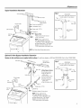 5
5
-
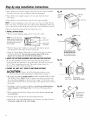 6
6
-
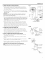 7
7
-
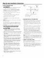 8
8
-
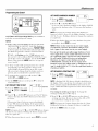 9
9
-
 10
10
-
 11
11
-
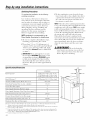 12
12
-
 13
13
-
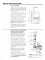 14
14
-
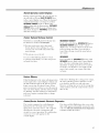 15
15
-
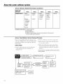 16
16
-
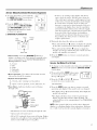 17
17
-
 18
18
-
 19
19
-
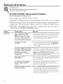 20
20
-
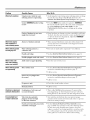 21
21
-
 22
22
-
 23
23
-
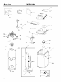 24
24
-
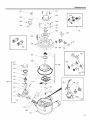 25
25
-
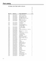 26
26
-
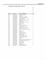 27
27
-
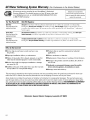 28
28
-
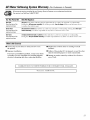 29
29
-
 30
30
-
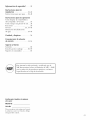 31
31
-
 32
32
-
 33
33
-
 34
34
-
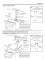 35
35
-
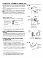 36
36
-
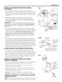 37
37
-
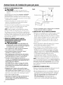 38
38
-
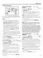 39
39
-
 40
40
-
 41
41
-
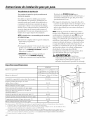 42
42
-
 43
43
-
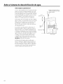 44
44
-
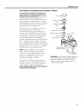 45
45
-
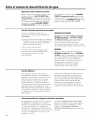 46
46
-
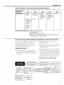 47
47
-
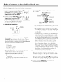 48
48
-
 49
49
-
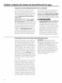 50
50
-
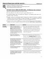 51
51
-
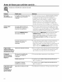 52
52
-
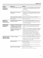 53
53
-
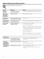 54
54
-
 55
55
-
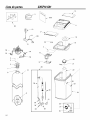 56
56
-
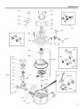 57
57
-
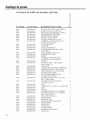 58
58
-
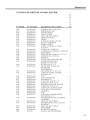 59
59
-
 60
60
-
 61
61
-
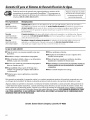 62
62
-
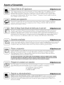 63
63
-
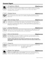 64
64


GE GXSF18G02 El manual del propietario
- Tipo
- El manual del propietario
- Este manual también es adecuado para
en otros idiomas
- English: GE GXSF18G02 Owner's manual
Artículos relacionados
-
GE GXSF39E01 El manual del propietario
-
-
 GE Monogram GXSF18G Manual de usuario
-
 GE Monogram GXSF18G Manual de usuario
-
GE GXSH39E02 El manual del propietario
-
-
GE GXSH45V El manual del propietario
-
-
-

