CARLO GAVAZZI ET272DINMV53X2SX Guía de instalación
- Tipo
- Guía de instalación

ET272
ITALIANO
Avvertenze
PERICOLO! Par soo tensione. Arresto
cardiaco, bruciature e altre lesioni.
• Scollegare l’alimentazione e i carichi prima
di installare il trasduore di energia.
• Ulizzare il trasduore di energia solo alla
tensione e corrente specicate.
• L’installazione dei trasduori di energia
deve essere eseguita solo da persone che
sappiano operare in sicurezza.
• La sicurezza di qualsiasi sistema che
incorpora il trasduore di energia ricade
soo la responsabilità dell’installatore del
sistema.
•
Non rimuovere la protezione se i terminali
9-10-11-12 non sono collega.
AVVISO: nessuno è autorizzato ad aprire
il trasduore di energia. Solo il
personale dell’assistenza tecnica CARLO
GAVAZZI può farlo.
Questo manuale è parte integrante del
prodoo. Deve essere consultato per
l’installazione del trasduore di energia.
Deve essere mantenuto in buone condizioni e
conservato in un luogo pulito e accessibile agli
operatori.
Pulizia
Usare un panno leggermente inumidito. Non
usare abrasivi o solven.
Assistenza e garanzia
In caso di malfunzionamento, guasto, necessità
informazioni o per acquistare moduli accessori
e/o sensori di corrente, contaare la liale
CARLO GAVAZZI o il distributore nel paese
di appartenenza. L’installazione e l’uso del
trasduore di energia diversi da quanto indicato
nelle istruzioni fornite invalidano la garanzia.
Raccomandazioni importan
Conservare la busna autoadesiva contenente
le echee o le echee (vedere “Ulizzo delle
echee adesive”).
Anché la procedura di indirizzamento e
congurazione vada a buon ne, la rete RS485
deve essere costuita da soli ET272 ed un
VMU-C Master (un VMU-C ogni max 80 ET272).
Installaon instrucon
Mul-channel energy transducer for three-phase systems for DIN rail installaon
Istruzioni per l’installazione
Trasduore di energia mul canale per sistemi trifase, per installazione a guida DIN.
Installaonsanweisung
Mulkanal-Energiewandler für Dreiphasensysteme zur Installaon auf
DIN-Schiene.
Instrucons pour l’installaon
Transducteur d’énergie mulcanal pour systèmes triphasés, avec possibilité d’installaon par rail
DIN.
Instrucciones para la instalación
Transductor de energía mulcanal para sistemas trifásicos, instalable con carril DIN.
Vejledning l installaon
Flerkanals energitransformer l trefasede systemer, som kan installeres på DIN-skinne.
ENGLISH ITALIANO
Package content
A. ET272 energy transducer
B. Terminal for cascade connecon
C. Self-adhesive transparent bag
D. Small self-adhesive label with SIN code
E. Large self-adhesive label with SIN code
F. Installaon manual
Contenuto della confezione
A. Trasduore di energia ET272
B. Morseo per il collegamento a cascata
C. Busna trasparente autoadesiva
D. Echea autoadesiva piccola con codice SIN
E. Echea autoadesiva grande con codice SIN
F. Manuale installazione
DEUTSCH FRANÇAIS
Packungsinhalt
A. Energiewandler ET272
B. Klemme für Kaskadenschaltung
C. Selbstklebender, durchsichger Beutel
D. Kleines Selbstklebeeke mit SIN- Code
E. Großes Selbstklebeeke mit SIN- Code
F. Installaonsanleitung
Contenu de l‘emballage
A. Transducteur d’énergie ET272
B. Borne pour la connexion en cascade
C. Sachet transparent autocollant
D. Pete équee autocollante avec code SIN
E. Grande équee autocollante avec code
SIN
F. Manuel d’installaon
ESPAÑOL DANSK
Contenido del embalaje
A. Transductor de energía ET272
B. Borne para la conexión en cascada
C. Sobrecito transparente autoadhesivo
D. Equeta autoadhesiva pequeña con
código SIN
E. Equeta autoadhesiva grande con código
SIN
F. Manual de instalación
Pakkens indhold
A. Energitransformer ET272
B. Klemme l kaskadelslutning
C. Selvklæbende transparent konvolut
D. Lille klæbemærkat med SIN-kode
E. Stor klæbemærkat med SIN-kode
F. Installaonsvejledning
1
432
Montaggio di ET272 sulla guida DIN
(g. 2) e rimozione (g. 3)
Prestare aenzione alla rimozione dello
strumento dalla guida DIN al ne di evitare la
roura del sostegno. Un’eccessiva rotazione
dello strumento in fase di smontaggio potrebbe
causare la roura del sostegno, come illustra la
gura 3. Si consiglia di slarlo verso il basso.
Ulizzo delle echee adesive
(g. 1/4, C/D/E)
Nel caso ciascun ET272 sia installato in una
dierente cassea, si consiglia di ulizzare le
echee idencave [D, E] in dotazione, uli
a facilitare ed accelerare le successive fasi di
installazione e messa in servizio.
ETICHETTA [E]:
idenca visivamente il trasduore installato
nella cassea (anche a distanza).
Aaccarla sull’esterno della cassea in
posizione visibile anche dopo l’installazione
(es.: vedi g. 4 E).
ETICHETTA [D]:
serve alla preparazione della lista di messa in
servizio (vedi “Procedura di compilazione lista
di messa in servizio”), dovrà essere disponibile
durante la fase di installazione delle cassee
(in loco). Aaccare la busta trasparente [C]
contenente l’echea [D] sull’esterno della
cassea in una zona accessibile durante
l’installazione (es.: vedi g. 4 C).
ENGLISH
Warnings
DANGER! Live parts. Heart aack,
burns and other injuries.
• Disconnect the power supply and the loads
before installing the energy transducer.
• Only use the energy transducer at the
specied voltage and current.
• The energy transducers should only be
installed by technicians who can operate
safely.
• The system installer is liable for the safety
of any system that includes the energy
transducer.
•
Never remove the protecon if terminals
9-10-11-12 are not connected.
WARNING: nobody is authorised to
open the energy transducer. The
operaon can only be performed by
CARLO GAVAZZI technical support personnel.
This manual is an integral part of the
product. It must be referred to for the
installaon of the energy transducer. It
must be kept in good condion and in a clean
locaon accessible to all operators.
Cleaning
Use a slightly dampened cloth to clean the
display. Do not use abrasives or solvents.
Support and warranty
In the event of malfuncon, fault, requests for
informaon or to purchase accessory modules
and/or current sensors, contact the CARLO
GAVAZZI branch or distributor in your country.
Installaon and use of analyzers other than
those indicated in the provided instrucons and
removal of the MABC module void the warranty.
Important recommendaons
Keep the self-adhesive bag containing the
labels, or the labels themselves (see “Using the
adhesive labels”).
For the addressing and conguraon procedure
to be successful, the RS485 network must
consist of ET272 only and of a VMU-C Master (a
VMU-C every 80 ET272 at most).
Installing (g. 2) and removing (g.
3) the ET272 energy transducer on/
from the DIN rail
Be careful when removing the instrument from
the DIN rail, to avoid breaking the support.
Turning the instrument too much when
removing it might cause the support to break,
as shown in gure 3. We recommend that you
withdraw it downward.
Using the adhesive labels
(g. 1/4, C/D/E)
If each ET272 is installed in a dierent box,
we recommend that you use the supplied
idencaon labels [D, E], for easier and faster
installaon and commissioning.
[E] LABEL:
it visually idenes the transducer installed in
the box (even from afar).
Ax it on the box outer surface, in a locaon
where it can be seen even aer installaon
(e.g.: see g. 4 E).
[D] LABEL:
it is used for lling in the commissioning list
(see “Commissioning list ll-in procedure”);
it shall be available during the box installaon
procedure (on site). Ax the [C] transparent
bag containing the [D] label on the box outer
surface, in a locaon that is accessible during
installaon (e.g.: see g. 4 C).
DEUTSCH
Hinweise
GEFAHR! Unter Spannung stehende
Teile. Herzsllstand, Verbrennungen
und sonsge Verletzungen.
• Vor Installaon des Energiewandlers
müssen die Stromversorgung und die
Lasten abgetrennt werden.
• Den Energiewandler ausschließlich mit
der angegebenen Spannung und dem
angegebenen Strom betreiben.
• Die Installaon der Energiewandleren darf
ausschließlich von Personen vorgenommen
werden, die in der Lage sind, unter
Sicherheitsbedingungen zu arbeiten.
• Die Sicherheit jedes Systems, in welches
der Energiewandler eingebaut wird, liegt in
der Verantwortung derjenigen Person, die
das System installiert.
•
Die Schutzhülle nicht enernen, solange
die Anschlüsse 9-10-11-12 nicht
angeschlossen sind.
WARNHINWEIS: es ist niemandem
gestaet, den Energiewandler zu önen.
Dies ist nur dem Kundendienstpersonal
der Fa. CARLO GAVAZZI gestaet.
Diese Anleitung ist wesentlicher Bestandteil
des Produkts. Sie muss zur Installaon des
Energiewandlers herangezogen werden.
Diese Anleitung muss in einwandfreiem Zustand
gehalten und an einem sauberen, für die Bediener
zugänglichen Ort auewahrt werden.
Reinigung
Einen leicht angefeuchteten Lappen verwenden.
Keine Scheuer- oder Lösungsmiel verwenden.
Kundendienst und Garane
Bei Funkonsstörungen, Ausfall, Anforderung von
Informaonen oder Erwerb von Zusatzmodulen
und/oder Stromsensoren bie Kontakt mit der
Filiale CARLO GAVAZZI oder mit dem Händler im
Installaonsland aufnehmen Von den Angaben dieser
Anleitung abweichende Installaon und Betrieb des
Energiewandlers führen zur Ungülgkeit der Garane.
Wichge Empfehlungen
Den Selbstklebebeutel mit den Ekeen
bzw. die Ekeen (siehe "Verwendung der
Selbstklebeekeen”) auewahren. Um eine
erfolgreiche Adressierung und Konguraon zu
gewährleisten, darf das Netz RS485 ausschließlich
aus ET272 und einem VMU-C Master bestehen (ein
VMU-C pro max. 80 Geräten ET272).
Montage (Abb. 2) und Demontage
(Abb. 3) des ET272 auf/von der DIN-
Schiene
Bei der Demontage des Instruments von der
DIN-Schiene ist Vorsicht geboten, um den Bruch
der Halterung zu vermeiden. Ein übermäßiges
Drehen des Instruments beim Demoneren
könnte zum Bruch der Halterung führen, wie
in Abb. 3 dargestellt. Es empehlt sich, das
Instrument nach unten abzuziehen.
Verwendung der Selbstklebeekeen
(Abb. 1/4, C/D/E)
Sofern jeder ET272 in einem anderen
Kasten installiert ist, empehlt es sich, die
mitgelieferten Kennzeichnungsekeen [D, E]
zu verwenden, um die spätere Installaon und
Inbetriebnahme zu erleichtern.
ETIKETT [E]:
Visuelle (auch aus der Enernung sichtbare)
Kennzeichnung des im Kasten installierten
Wandlers.
Das Eke außen am Kasten so anbringen, dass
es auch nach der Installaon gut sichtbar ist
(z.B. siehe Abb. 4 E).
ETIKETT [D]:
Dient zur Vorbereitung der Inbetriebnahme-Liste
(siehe “Ausfüllen der Inbetriebnahme-Liste”) und
muss bei Installaon der Kästen (vor Ort) zur
Verfügung stehen. Den durchsichgen Beutel
[C] mit dem Eke [D] außen am Kasten in
einem Bereich anbringen, der auch während der
Installaon zugänglich ist (z.B. siehe Abb. 4 C).
FRANÇAIS
Averssements
DANGER ! Pièces sous tension. Crise
cardiaque, brûlures et autres blessures
• Déconnecter l’alimentaon et les charges
avant d’installer le transducteur d’énergie.
• Uliser le transducteur d’énergie
seulement à la tension et au courant
spéciés.
• L’installaon des transducteurs d’énergie
d’énergie doit être eectuée seulement par
des personnes sachant opérer en sécurité.
• La sécurité de tout système qui incorpore
le transducteur d’énergie retombe sous la
responsabilité de l’installateur du système.
•
Ne pas rerer la protecon si les bornes
9-10-11-12 ne sont pas connectées.
AVIS : personne n’est autorisé à ouvrir le
transducteur d’énergie. Seul le personnel
de l’assistance technique CARLO
GAVAZZI peut le faire.
Ce manuel fait pare intégrante du
produit. Il doit être consulté pour
l’installaon du transducteur d’énergie.
Il doit être maintenu dans de bonnes condions
et conservé dans un lieu propre et accessible
aux opérateurs.
Neoyage
Uliser un chion légèrement humidié. Ne pas
uliser d’abrasifs ou de solvants.
SERVICE ET GARANTIE
En cas de dysfonconnement, de panne, de
besoin d'informaons, ou pour acheter des
modules accessoires et/ou des capteurs de
courant, contacter la liale ou le distributeur
CARLO GAVAZZI de votre pays. Une installaon
et une ulisaon du transducteur d’énergie
autres que celles indiquées dans les instrucons
fournies invalident la garane.
Recommandaons importantes
Conserver le sachet autocollant contenant
les équees (voir “Ulisaon des équees
autocollantes”).
An que la procédure d’adressage et
conguraon réussisse, le réseau RS485 doit
être constué exclusivement de ET272 et d’un
VMU-C Maître (un VMU-C tous les 80 ET272
max).
Montage de ET272 sur le rail DIN
(g. 2) et retrait (g. 3)
Prêter aenon lors du retrait de l’instrument
du rail DIN de sorte à éviter de briser le support.
Une rotaon excessive de l’instrument en
phase de démontage pourrait briser le support,
comme illustré sur la gure 3. Il est recommandé
de l'ôter par le bas.
Ulisaon des équees
autocollantes
(g. 1/4, C/D/E)
Au cas où chaque ET272 serait installé dans
une boîte diérente, on recommande d’uliser
les équees d’idencaon [D, E] fournies,
qui servent à faciliter et à accélérer les phases
subséquentes d’installaon et de mise en
service.
ÉTIQUETTE [E] :
idene visuellement le transducteur installé
dans la boîte (même à distance).
L’apposer sur l'extérieur de la boîte en posion
visible même après l’installaon (ex. : voir g.
4 E).
ÉTIQUETTE [D] :
sert à la préparaon de la liste de mise en
service (voir “Procédure de renseignement liste
de mise en service”), elle devra être disponible
durant la phase d’installaon des boîtes (in situ).
Apposer le sachet transparent [C] contenant
l’équee [D] sur l’extérieur de la boîte dans
une zone accessible durant l’installaon (ex. :
voir g. 4 C).
ESPAÑOL
Advertencias
¡PELIGRO! Elementos somedos a
tensión. Ataque al corazón,
quemaduras u otras lesiones.
• Desconecte la fuente de alimentación y
las cargas antes de instalar el transductor
de energía.
• Ulizar el transductor de energía solo a la
tensión y corriente especicadas.
• La instalación de los transductores de
energía de energía solo deberá correr a
cargo de personas que sepan operar de
forma segura.
• La seguridad de cualquier sistema que
incorpora el transductor de energía
será responsabilidad del instalador del
sistema.
•
No quitar la protección si los terminales
9-10-11-12 no están conectados.
AVISO: nadie está autorizado para
abrir el transductor de energía. Solo el
personal de la asistencia técnica
CARLO GAVAZZI puede hacerlo.
Este manual forma parte integrante del
producto. Debe consultarse para
instalar el transductor de energía. Debe
mantenerse en buenas condiciones y
conservarse en un lugar limpio y accesible a
los operadores.
Limpieza
Usar un paño ligeramente húmedo. No usar
abrasivos ni disolventes.
Asistencia y garana
En caso de fallo de funcionamiento, avería,
necesidad de información o para adquirir
módulos accesorios y/o sensores de
corriente, contactar a la lial CARLO GAVAZZI
o al distribuidor en el país de pertenencia. La
instalación y el uso del transductor de energía
diferentes de lo indicado en las instrucciones
facilitadas y la rerada del módulo MABC
invalidan la garana.
Recomendaciones importantes
Conservar el sobrecito autoadhesivo que
conene las equetas o las equetas (ver
«Uso de las equetas adhesivas»).
Para que el procedimiento de direccionamiento
y conguración llegue a buen puerto, la red
RS485 debe estar compuesta únicamente por
ET272 y un VMU-C Master (un VMU-C cada
máx. 80 ET272).
Montaje de ET272 en el carril DIN
(g. 2) y rerada (g. 3)
Prestar atención durante la rerada del
instrumento del carril DIN para evitar la rotura
de la sujeción. Una excesiva rotación del
instrumento en fase de desmontaje podría
causar la rotura de la sujeción, como se
muestra en la gura 3. Se recomienda sacarlo
hacia abajo.
Uso de las equetas adhesivas
(g. 1/4, C/D/E)
En caso de que haya algún ET272 instalado en
una caja diferente, se recomienda ulizar las
equetas idencavas [D, E] suministradas,
úles para facilitar y acelerar las siguientes
fases de instalación y puesta en servicio.
ETIQUETA [E]:
idenca visualmente el transductor instalado
en la caja (incluso a distancia).
Pegarla en el exterior de la caja en un lugar
visible incluso después de la instalación (ej.:
véase g. 4 E).
ETIQUETA [D]:
sirve para la preparación de la lista de
puesta en servicio (véase «Procedimiento
de cumplimentación de la lista de puesta en
servicio») y deberá estar disponible durante la
fase de instalación de las cajas (in situ). Fijar
el sobrecito transparente [C] que conene la
equeta [D] al exterior de la caja en una zona
accesible durante la instalación (ej.: véase g.
4 C).
DANSK
Advarsler
FARE! Spændingsførende dele.
Hjerteanfald, forbrændinger og andre
kvæstelser.
• Aryd strømforsyningen og
belastningerne, inden energitransformer
energitransformer installeres.
• Energitransformer må kun bruges ved den
angivne spænding og strøm.
• Energitransformere må kun installeres af
fagkyndigt/autoriseret personale, som
ved, hvordan man arbejder i sikkerhed.
• Sikkerheden for et hvilket som helst
system, som omfaer energitransformer,
er installatørens ansvar.
•
Beskyelsen må ikke ernes, hvis
terminalerne 9-10-11-12 ikke er
lsluede.
ADVARSEL: Ingen er autoriseret l at
åbne energitransformer. Kun teknikere
fra CARLO GAVAZZI må gøre dee.
Denne manual er en integreret del af
produktet. Den skal læse før installaon
af energitransformer. Den skal
opbevares i god stand på et rent sted, som er
let lgængeligt for operatørerne.
Rengøring
Brug en fugg klud. Brug aldrig slibemidler
eller opløsningsmidler.
Service og garan
Hvis der opstår fejlfunkoner og defekter,
eller hvis der er brug for oplysninger, eller
der skal købes lbehørsmoduler og/eller
strømsensorer, bedes du kontakte den
lokale CARLO GAVAZZI-forhandler eller
-afdeling. Ved installaon og brug af andre
energitransformerer end den, der er angivet
i den medfølgende vejledning, boralder
garanen.
Vigge anbefalinger
Gem den selvklæbende konvolut
indeholdende mærkaten eller mærkaterne (se
“Anvendelse af klæbemærkaterne”).
For at proceduren for adressering og
konguraon skal være korrekt, må RS485-
neet kun bestå af ET272 og en VMU-C Master
(en VMU-C for maks. hver 80 ET272).
Montering af ET272 på DIN-skinne
(g. 2) og ernelse heraf (g. 3)
Vær forsigg ved ernelse af instrumentet
fra DIN-skinnen for at undgå, at holderen
går i stykker. En overdreven drejning af
instrumentet under afmontering kan medføre,
at holderen går i stykker, som illustreret på g.
3. Det anbefales at trække det nedad.
Anvendelse af klæbemærkaterne
(g. 1/4, C/D/E)
Hvis hvert ET272 er installeret i hver sin boks,
anbefales det at bruge id-mærkaterne [D, E]
(medfølger), som er lee at bruge og gør den
eerfølgende installaon og ibrugtagning
meget hurgere.
MÆRKAT [E]:
Idencerer visuelt transduceren, som er
installeret i boksen (også ved ernstyring).
Påføres synligt uden på boksen eer
installaonsfasen (f.eks.: se g. 4 E).
MÆRKAT [D]:
Bruges l klargøring af listen over ibrugtagning
(se “Procedure for kompilering af listen over
ibrugtagning”) og skal være l rådighed under
installaon af boksen (på stedet). Påfør den
gennemsigge konvolut [C] indeholdende
mærkaten [D] uden på boksen i et område,
som er lgængeligt under installaonen
(f.eks.: se g. 4 C).

CARLO GAVAZZI Controls SpA
via Saorze, 8 32100 Belluno (BL)Italy
www.gavazziautomaon.com
info@gavazzi-automaon.com
info: +39 0437 355811 / fax: +39 0437 355880
www.productselecon.net 2017-07 | 8021478| COPYRIGHT ©2017
Instrucon manual TCD_MM EN: www.productselecon.net/MANUALS/UK/tcdmm_im.pdf
Instrucon manual TCD_M EN: www.productselecon.net/MANUALS/UK/tcdxm_im.pdf
www.productselecon.net
Installing ET272 / Installare l‘ET272 / Installaon des ET272 / Installer le ET272 / Instalar el ET272 / Installer ET272
ENGLISH
FRANÇAIS
ITALIANO
ESPAÑOL
DEUTSCH
DANSK
Caraerische eleriche
Alimentazione Autoalimentato
Consumo 2 W, ≤ 4 VA
Ingressi di corrente tramite TCD_M
Tensione nominale 160 – 240 V L-N, 277 – 415 V L-L
Tolleranza tensione -10%, +10%
Frequenza Da 45 a 65 Hz
Classe di precisione Vedi “Scheda tecnica”, scaricabile dal sito di Carlo Gavazzi
Porta RS485
Protocollo Modbus RTU
Tipo connessione Morsetti sconnettibili, 2 fili, distanza massima 1000 m
Caraerische ambientali
Temperatura di esercizio Da -25 a +55 °C / da -13 a +131 °F
Temperatura di stoccaggio Da -30 a +70 °C / da -22 a +158 °F
Caraerische generali
Morse sconnebili
Grado di protezione Frontale: IP40, Terminali: IP20
Responsabilità di smalmento. Smalre con raccolta dierenziata tramite le struure di
raccolte indicate dal governo o dagli en pubblici locali. Il correo smalmento e il riciclag-
gio aiuteranno a prevenire conseguenze potenzialmente negave per l’ambiente e per le
persone.
[5] schema di collegamento ingressi voltmetrici ed amperometrici.
[6] schema di collegamento della porta seriale RS485.
[7] schema di collegamento in cascata degli ingressi voltmetrici.
5 6
7
Electrical features
Power supply Self-powered
Consumpon 2 W, ≤ 4 VA
Current inputs via TCD_M
Rated voltage 160 – 240 V L-N, 277 – 415 V L-L
Voltage tolerance -10%, +10%
Frequency 45 to 65 Hz
Accuracy class Please refer to the “Technical data sheet”, which can be
downloaded from the Carlo Gavazzi website
RS485 Port
Protocol Modbus RTU
Connection type Detachable terminals, 2 wires, maximum distance 1000 m
Environment characteriscs
Operang temperature -25 to +55 °C/-13 to +131 °F
Storage temperature -30 to +70 °C/-22 to +158 °F
General features
Terminals detachable
Protecon Degree Front: IP40, Terminals: IP20
Responsibility for disposal. The product must be disposed of at the relave recycling cen-
ters specied by the government or local public authories. Correct disposal and recycling
will contribute to the prevenon of potenally harmful consequences to the environment
and persons.
[5] voltage and current input connecon diagram.
[6] RS485 serial port connecon diagram.
[7] voltage input cascade connecon diagram.
Elektrische Merkmale
Stromversorgung Eigenversorgt
Verbrauch 2 W, ≤ 4 VA
Stromeingänge über TCD_M
Nennspannung 160 – 240 V L-N, 277 – 415 V L-L
Spannungstoleranz -10% +10%
Frequenz 45 bis 65 Hz
Präzisionsklasse Siehe “Technisches Datenbla”. Kann von der Website der Fa.
Carlo Gavazzi heruntergeladen werden
Port RS485
Protokoll Modbus RTU
Verbindungsart Abnehmbare Klemmen, 2 Leiter, max. Entfernung 1000 m
Umgebungsmerkmale
Betriebstemperatur -25 bis +55 °C/ -13 bis +131 °F
Lagertemperatur -30 bis +70 °C/ -22 bis +158 °F
Allgemeine Merkmale
Klemmen Abnehmbar
Schutzart Frontseite: IP40, Anschlüsse: IP20
Verantwortlichkeit für die Entsorgung. Es muss für getrennte Abfallentsorgung anhand der
von der Regierung oder den öentlichen Lokalbehörden benannten Sammelstrukturen ge-
sorgt werden. Die korrekte Entsorgung bzw. das Recycling tragen dazu bei, potenell nega-
ve Auswirkungen auf die Umwelt und die Personen zu vermeiden.
[5] Anschlussplan Spannungs- und Strommesseingänge.
[6] Anschlussplan des seriellen Ports RS485.
[7] Kaskaden-Anschlussplan der Spannungsmesseingänge.
Caractérisques électriques
Alimentaon Auto-alimenté
Consommaon 2 W, ≤ 4 VA
Entrées de courant via TCD_M
Tension nominale 160 – 240 V L-N, 277 – 415 V L-L
Tolérance tension -10% +10%
Fréquence De 45 à 65 Hz
Classe de précision Voir “Fiche technique”, téléchargeable depuis le site de Carlo
Gavazzi
Port RS485
Protocole Modbus RTU
Type de connexion Bornes déconnectables, 2 fils, distance maximum 1000 m
Caractérisques
environnementales
Température de fonconnement De -25 à +55 °C / de -13 à +131 °F
Température de stockage De -30 à +70 °C / de -22 à +158 °F
Caractérisques générales
Bornes déconnectables.
Indice de protecon Face avant : IP40, Bornes : IP20
Responsabilité en maère d’éliminaon. Éliminer selon le tri sélecf avec les structures de
récupéraon indiquées par l’État ou par les organismes publics locaux. Bien éliminer et re-
cycler aidera à prévenir des conséquences potenellement néfastes pour l’environnement
et les personnes.
[5] schéma de branchement entrées voltmétriques et ampérométriques.
[6] schéma de branchement du port série RS485.
[7] schéma de branchement en cascade des entrées voltmétriques.
Caracteríscas eléctricas
Alimentación Autoalimentado
Consumo 2 W, ≤ 4 VA
Entradas de intensidad mediante TCD_M
Tensión nominal 160 – 240 V L-N, 277 – 415 V L-L
Tolerancia de la tensión -10 %, +10 %
Frecuencia de 45 a 65 Hz
Clase de precisión Véase la «Ficha técnica», descargable desde el sio de Carlo
Gavazzi
Puerto RS485
Protocolo Modbus RTU
Tipo de conexión Bornes desconectables, 2 hilos, distancia máxima 1000 m
Especicaciones
medioambientales
Temperatura de funcionamiento De -25 a +55 °C / de -13 a +131 °F
Temperatura de
almacenamiento
De -30 a +70 °C / de -22 a +158 °F
Caracteríscas generales
Bornes desconectables.
Grado de protección Frontal: IP40, Terminales: IP20
Responsabilidad de eliminación. Eliminar mediante recogida selecva a través de las
estructuras de recogida indicadas por el gobierno o por los entes públicos locales. La correc-
ta eliminación y el reciclaje ayudarán a prevenir consecuencias potencialmente negavas
para el medioambiente y para las personas.
[5] esquema de conexión de entradas volmétricas y amperométricas.
[6] esquema de conexión del puerto de serie RS485.
[7] esquema de conexión en cascada de las entradas volmétricas.
Elektriske egenskaber
Strømforsyning Automask justering
Forbrug 2 W, ≤ 4 VA
Strømindgange vha. TCD_M
Nominel spænding 160 – 240 V L-N, 277 – 415 V L-L
Spændingstolerance -10% +10%
Frekvens Fra 45 l 65 Hz
Nøjagghedsklasse Se “Teknisk beskrivelse”, som kan downloades fra Carlo Gavazzis
website
RS485-port
Protokol Modbus RTU
Tilslutningstype Klemmer, der kan frakobles, 2 ledninger, maks. afstand 1000 m
Miljømæssige egenskaber
Dristemperatur Fra -25 l +55 °C/fra -13 l +131 °F
Opbevaringstemperatur Fra -30 l +70 °C/fra -22 l +158 °F
Generelle egenskaber
Klemmer Klemmer, der kan frakobles
Beskyelsesgrad Front: IP40, terminaler: IP20
Ansvar vedrørende bortskaelse. Sorteres og bortskaes på genbrugsplads, som angivet af
stat eller kommune. Den korrekte bortskaelse og genbrug er med l at forhindre potenelt
negave følger for miljøet og personer.
[5] Tilslutningsdiagram voltmeter- og amperemeteradgange.
[6] Tilslutningsdiagram for den serielle port RS485.
[7] Tilslutningsdiagram i kaskade for voltmeterindgange.
2014/30/EU
2011/65/EU
EN61010-1
EN62052-11
EN62053-21

ET272
ITALIANO
21
ENGLISH
DEUTSCH FRANÇAIS
Commissioning procedure
When duly lled-in, the commissioning list will streamline the subsequent automac addressing
and conguraon of the ET272s.
Procedura di messa in servizio
La lista di messa in servizio, debitamente compilata, agevolerà le successive operazioni di indiriz-
zamento automaco e congurazione degli ET272.
Inbetriebnahme- Prozedur
Die ordnungsgemäß ausgefüllte Inbetriebnahme-Liste erleichtert die Abläufe zur automaschen
Adressierung und Konguraon der ET272.
Procédure de mise en service
La liste de mise en service, dûment remplie, facilitera les opéraons subséquentes d’adressage
automaque et de conguraon des ET272.
Procedimiento de puesta en servicio
La lista de puesta en servicio, debidamente cumplimentada, agilizará las operaciones posteriores
de direccionamiento automáco y conguración de los ET272.
Procedure for ibrugtagning
Listen over ibrugtagning, behørigt udfyldt, gør det leere at udføre de eerfølgende handlinger
for automask adressering og for konguraon af ET272.
AVVISO: prima di aaccare l’echea [A] sulla lista di messa in servizio, vericare
la corrispondenza tra il codice SIN [B] e il codice riportato sullo strumento ET272
installato nella cassea di derivazione.
Questo manuale è parte integrante del prodoo ET272. Deve essere mantenuto
in buone condizioni e conservato in un luogo pulito e accessibile agli operatori.
Introduzione
La lista di messa in servizio [D/E] associa ad ogni ET272 (idencato dal codice SIN [B]) la
posizione sica di installazione (idencata da un numero progressivo, da 1 a max 80).
Consigliamo la correa compilazione della lista di messa in servizio, essa agevolerà
le successive operazioni di indirizzamento automaco e congurazione degli ET272
mediante la funzione dedicata disponibile nell’interfaccia WEB del VMU-C (vedere il
manuale di istruzioni in linea di VMU-C).
Procedura consigliata di messa in servizio
Passo Azione
1
Verica preliminare:
Se... Allora...
disponete della lista
completa con i codici SIN
[E]
installate le cassee di derivazione (CDD) con
il codice SIN [B] nella posizione prestabilita
dall’impianto elerico e andate al passo
6. Nota: numero progressivo idenca la
posizione della CDD nell’impianto.
disponete della lista da
completare [D]
procedete con i passi da 2 a 7.
non disponete della lista da
completare [D]
scaricate il le da www.productselecon.
net/MANUALS/UK/et272_sinlist.pdf e
procedete con i passi da 2 a 7.
2
Prendete l’echea piccola [A] (dimensioni 50 x 25 mm), contenuta
all’interno della busna trasparente aaccata alla CDD:
Se... Allora...
trovate l’echea aaccatela nella colonna “Nome” della lista
[D] nella riga col numero corrispondente alla
posizione sica di installazione della cassea
nell’impianto.
non trovate l’echea trascrivete manualmente il codice SIN [B]
sulla lista copiandolo dall’echea grande
[C] (dimensioni 70 x 44 mm).
3
Installate la cassea di derivazione.
4
Ripetete i passi da 2 a 3 no ad installazione completata.
5
Assicuratevi che il VMU-C sia presente nella rete di ET272 (max 80) e
collegato tramite RS485 (vedi il manuale di istruzioni del VMU-C). [g 2]
6
Consegnate la lista completa di tue le echee [E] a chi eseguirà la messa
in servizio.
7
Ulizzate la funzione dedicata disponibile nell’interfaccia WEB del VMU-C per
eseguire la messa in servizio con indirizzamento e congurazione automaca
(vedere le istruzioni in linea nel soware o scaricabili dal sito
www.productselecon.net/MANUALS/IT/vmucemimex.pdf).
HINWEIS: bevor das Eke [A] auf der Inbetriebnahme-Liste angebracht wird,
muss die Übereinsmmung zwischen SIN-Code [B] und dem Code geprü werden,
der auf dem im Abzweigkasten installierten Instrument ET272 angegeben ist.
Diese Anleitung ist wesentlicher Bestandteil des Produkts ET272. Diese Anleitung
muss in einwandfreiem Zustand gehalten und an einem sauberen, für die
Bediener zugänglichen Ort auewahrt werden.
Einführung
Die Inbetriebnahme-Liste [D/E] ordnet jedem ET272 (durch SIN-Code [B] idenziert)
die physische Einbauposion zu (laufende Nummer zwischen 1 und maximal 80) zu.
Es empehlt sich, die Inbetriebnahme-Liste korrekt auszufüllen, da sie die nachfolgenden
Arbeitsgänge zur automaschen Adressierung und Konguraon der ET272 anhand der
entsprechenden Funkon erleichtert, die auf der WEB-Schnistelle des VMU-C zur
Verfügung steht (siehe Online- Betriebsanleitung des VMU-C).
Empfohlene Inbetriebnahme- Prozedur
Schri Maßnahme
1
Vorherige Überprüfung:
Wenn... Dann...
Sie über die komplee
Liste mit den SIN- Codes
verfügen [E]
installierten Sie die Abzweigkästen (CDD)
mit dem SIN- Code [B] in der von der
Elektroanlage vorgegebenen Posion. Dann
weiter mit Schri 6. Hinweis: die fortlaufende
Nummer idenziert die Posion der CDD in
der Anlage.
Sie über die zu ergänzende
Liste verfügen [D]
weiter mit Schri 2 bis 7.
Sie nicht über die zu
ergänzende Liste verfügen
[D]
laden Sie die Datei von da www.
productselecon.net/MANUALS/UK/et272_
sinlist.pdf herunter. Dann weiter mit Schri
2 bis 7.
2
Nehmen Sie das kleine Eke [A] (Größe 50 x 25 mm), das sich in dem
transparenten, an der CDD befesgten Beutel bendet:
Wenn... Dann...
Sie das Eke gefunden
haben
kleben Sie es in die Spalte “Name” der Liste
[D] in der Zeile mit der Nummer ein, die
der Installaons-Posion des Kastens in der
Anlage entspricht.
Sie das Eke nicht
gefunden haben
tragen Sie den SIN- Code [B] von Hand in
die Liste ein, indem Sie es von vom großen
Eke [C] (Größe 70 x 44 mm) abschreiben.
3
Installieren Sie den Abzweigkasten.
4
Wiederholen Sie die Schrie 2und 3 bis die Installaon vollständig ist.
5
Vergewissern Sie sich, dass der VMU-C im Netz ET272 (max. 80) vorhanden
und über RS485 angeschlossen ist (siehe Betriebsanleitung VMU-C). [Abb. 2]
6
Übergeben Sie die mit allen Ekeen [E] versehene Liste den Personen, die
die Inbetriebnahme vornehmen.
7
Verwenden Sie die spezische, auf der WEB-Schnistelle des VMU-C
verfügbare Funkon zur Ausführung der Inbetriebnahme mit automascher
Adressierung und Konguraon (siehe Online- Anleitung in der Soware oder
laden Sie sie von der Website herunter:
www.productselecon.net/MANUALS/IT/vmucemimex.pdf).
AVERTISSEMENT : avant d’apposer l’équee [A] sur la liste de mise en service,
vérier la correspondance entre le code SIN [B] et le code reporté sur l’instrument
ET272 installé dans la boîte de dérivaon.
Ce manuel fait pare intégrante du produit ET272. Il doit être maintenu dans de
bonnes condions et conservé dans un lieu propre et accessible aux opérateurs.
Introducon
La liste de mise en service [D/E] associe à chaque ET272 (idené par le code SIN [B])
la posion physique d’installaon (idenée par un numéro séquenel, de 1 à 80 max).
Nous conseillons de remplir correctement de la liste de mise en service, celle-ci
facilitera les opéraons subséquentes d’adressage automaques et de conguraon
des ET272 moyennant la foncon dédiée disponible dans l’interface WEB du VMU-C
(voir le manuel d'instrucons en ligne de VMU-C).
Procédure conseillée de mise en service
Étape Acon
1
Véricaon préliminaire :
Si... Alors...
vous disposez de la liste
complète avec les codes
SIN [E]
installez les boîtes de dérivaon (CDD) avec
le code SIN [B] dans la posion préétablie par
l’installaon électrique et passez à l’étape
6. Note : le numéro séquenel idene la
posion de la CDD dans l’installaon.
vous disposez de la liste à
compléter [D]
exécutez les étapes de 2 à 7.
vous ne disposez pas de la
liste à compléter [D]
téléchargez le chier à parr de www.
productselecon.net/MANUALS/UK/et272_
sinlist.pdf et exécutez les étapes de 2 à 7.
2
Prenez la pete équee [A] (dimensions 50 x 25 mm), contenue à l’intérieur
du sachet transparent aaché à la CDD :
Si... Alors...
vous trouvez l’équee collez-là dans la colonne “Nom” de la liste [D]
sur la ligne avec le numéro correspondant à
la posion physique d’installaon de la boîte
dans l’installaon.
vous ne trouvez pas
l’équee
transcrivez manuellement le code SIN [B]
sur la liste en le recopiant depuis la grande
équee [C] (dimensions 70 x 44 mm).
3
Installez la boîte de dérivaon.
4
Répétez les étapes de 2 à 3 jusqu’à ce que l’installaon soit complétée.
5
Assurez-vous que le VMU-C soit présent dans le réseau de ET272 (max 80) et
connecté via RS485 (voir le manuel d'instrucons du VMU-C). [g 2]
6
Remeez la liste de toutes les équees [E] à celui qui eectuera la mise en
service.
7
Ulisez la foncon dédiée disponible dans l’interface WEB du VMU-C pour
eectuer la mise en service avec adressage et conguraon automaque
(voir les instrucons en ligne dans le logiciel ou téléchargeables à parr du
site www.productselecon.net/MANUALS/IT/vmucemimex.pdf).
WARNING: before axing the [A] label on the commissioning list, verify that the SIN
code [B] matches the code found on the ET272 installed on the tap-o box.
This manual is an integral part of the ET272 product. It must be kept in good
condion and in a clean locaon accessible to all operators.
Preliminary remarks
The [D/E] commissioning list links each ET272 (idened by SIN code [B]) to its physical
installaon locaon (idened by a progressive number, from 1 to max. 80).
We recommend that you take care to properly ll in the commissioning list; it shall
streamline the subsequent automac addressing and conguraon of the ET272
through the dedicated funcon available in the WEB interface of the VMU-C (see the
online instrucon manual of the VMU-C).
Recommended commissioning procedure
Step Acon
1
Preliminary check:
If... Then...
you have the list lled in
with the SIN codes [E]
install the tap-o boxes (TOB) with SIN
code [B] in the locaon pre-dened by the
electrical system, then proceed with step 6.
Note: the progressive number idenes the
locaon of the TOB in the system.
you sll have to ll in the
[D] list
proceed with steps 2 to 7.
you do not have the list to
be lled in [D]
download the le from www.
productselecon.net/MANUALS/UK/et272_
sinlist.pdf, then proceed with steps 2 to 7.
2
Take the small label [A] (dimensions 50 x 25 mm) from inside the transparent
bag axed on the TOB:
If... Then...
you nd the label ax it in the “Name” column of the [D] list,
in the row whose number corresponds to
the box physical installaon locaon in the
system.
you do not nd the label manually record the SIN code [B] on the
list copying it from the large label [C]
(dimensions 70 x 44 mm).
3
Install the tap-o box.
4
Repeat steps 2 to 3 unl the installaon is completed.
5
Make sure the VMU-C exists in the network of ET272 (max 80) and is
connected by RS485 (see the instrucon manual of the VMU-C unit). [g 2]
6
Give the list complete with all the labels [E] to the personnel in charge of the
commissioning.
7
Use the dedicated funcon available in the web interface of the VMU-C to
perform the commissioning with automac addressing and conguraon
(please refer to the online instrucons which can be accessed from the
soware or downloaded from the site
www.productselecon.net/MANUALS/IT/vmucemimex.pdf).

CARLO GAVAZZI Controls SpA
via Saorze, 8 32100 Belluno (BL)Italy
www.gavazziautomaon.com
info@gavazzi-automaon.com
info: +39 0437 355811 / fax: +39 0437 355880
www.productselecon.net
8021801 | COPYRIGHT ©2017
www.productselecon.net
21
ESPAÑOL
DANSK
Commisioning list le www.productselecon.net/MANUALS/UK/et272_sinlist.pdf
Instrucon sheet ET272 www.productselecon.net/MANUALS/UK/et272_im.pdf
Instrucon manual VMU-C EM EN: www.productselecon.net/MANUALS/UK/vmucemimex.pdf
IT: www.productselecon.net/MANUALS/IT/vmucemimex.pdf
DE: www.productselecon.net/MANUALS/DE/vmucemimex.pdf
FR: www.productselecon.net/MANUALS/FR/vmucemimex.pdf
ES: www.productselecon.net/MANUALS/ES/vmucemimex.pdf
DA: www.productselecon.net/MANUALS/DK/vmucemimex.pdf
AVISO: antes de aplicar la equeta [A] en la lista de puesta en servicio, comprobar
la correspondencia entre el código SIN [B] y el código presente en el instrumento
ET272 instalado en la caja de derivación.
Este manual forma parte integrante del producto ET272. Debe mantenerse en
buenas condiciones y conservarse en un lugar limpio y accesible a los operadores.
Introducción
La lista de puesta en servicio [D/E] asocia a cada ET272 (idencado por el código SIN
[B]) la posición sica de instalación (idencada por un número progresivo, de 1 a máx.
80).
Aconsejamos la correcta cumplimentación de la lista de puesta en servicio, esta agilizará
las posteriores operaciones de direccionamiento automáco y conguración de los
ET272 mediante la función dedicada disponible en la interfaz WEB del VMU-C (véase el
manual de instrucciones en línea de VMU-C).
Procedimiento aconsejado de puesta en servicio
Paso Acción
1
Vericación preliminar:
Si... Entonces...
dispones de la lista
completa con los códigos
SIN [E]
instala la caja de derivación (CDD) con el
código SIN [B] en la posición preestablecida
por la instalación eléctrica y vete al paso
6. Nota: número progresivo idenca la
posición de la CDD en el sistema.
dispones de la lista a
completar [D]
procede con los pasos de 2 a 7.
no dispones de la lista a
completar [D]
descarga el archivo desde www.
productselecon.net/MANUALS/UK/et272_
sinlist.pdf y procede con los pasos de 2 a 7.
2
Toma la equeta pequeña [A] (dimensiones 50 x 25 mm), incluida en el
interior del sobrecito transparente pegado a la CDD:
Si... Entonces...
encuentras la equeta pégala en la columna "Nombre" de la lista [D]
en la línea con el número correspondiente a
la posición sica de instalación de la caja del
sistema.
no encuentras la equeta transcribe manualmente el código SIN [B] en
la lista copiándolo desde la equeta grande
[C] (dimensiones 70 x 44 mm).
3
Instala la caja de derivación.
4
Repite los pasos de 2 a 3 hasta nalizar la instalación.
5
Asegúrate de que el VMU-C esté presente en la red de ET272 (máx. 80) y
conéctalo mediante RS485 (véase el manual de instrucciones del VMU-C).
[g. 2]
6
Entrega la lista completa de todas las equetas [E] a la persona que realizará
la puesta en servicio.
7
Uliza la función dedicada disponible en la interfaz WEB del VMU-C
para realizar la puesta en servicio con direccionamiento y conguración
automáca (véanse las instrucciones en línea en el soware o que pueden
descargarse desde el sio
www.productselecon.net/MANUALS/IT/vmucemimex.pdf).
ADVARSEL: Inden påføring af mærkaten [A] på listen over ibrugtagning, skal du
kontrollere sammenpasningen mellem SIN-koden [B] og den kode, der er angivet
på instrumentet ET272, som er installeret i afgreningsmuen.
Denne manual er en integreret del af produktet ET272. Den skal opbevares i god
stand på et rent sted, som er let lgængeligt for operatørerne.
Indledning
Listen over ibrugtagning [D/E] forbinder ET272 (idenceret med SIN-koden [B]) med
installaonens fysiske posion (idenceret med et fortløbende tal fra 1 l maks. 80).
Vi anbefaler, at man følger den korrekte rækkefølge på listen over ibrugtagning. Det vil
gøre det leere at udføre de eerfølgende handlinger for automask adressering og
konguraon af ET272'er vha. den dedikerede funkon, der ndes i webgrænseaden i
VMU-C (se instrukonsmanualen for VMU-C).
Anbefalet procedure for ibrugtagning
Trin Handling
1
Første kontrol:
Hvis ... Skal du ...
have hele listen klar med
SIN-koder [E]
installere afgreningsmuerne (CDD) med
SIN-koden [B] i den korrekte posion for det
elektriske system og gå l trin 6. Bemærk: Det
fortløbende tal idencerer CDDs posion i
anlægget.
have den liste, der skal
følges, klar [D]
gå l trin 2-7.
du ikke har listen, der skal
følges [D], klar
skal du downloade len fra www.
productselecon.net/MANUALS/UK/et272_
sinlist.pdf og gå videre med trin 2-7.
2
Tag den lille mærkat [A] (dimensioner 50 x 25 mm), i den gennemsigge
konvolut, der er påsat CDD'en:
Hvis ... Skal du ...
nde mærkaten og sæe den på kolonnen “Navn” på listen
[D] på linjen med det nummer, der svarer l
afgreningsmuens fysiske posion.
du ikke kan nde mærkaten skal du manuelt skrive SIN-koden [B] på listen
ved at kopiere koden fra den store mærkat
[C] (dimensioner 70 x 44 mm).
3
Installer afgreningsmuen.
4
Gentag trin 2-3 for at fuldføre installaonen.
5
Sørg for, at VMU-C ndes i netværket for ET272 (maks. 80), og lslut via
RS485 (se instrukonsbogen for VMU-C). [g 2]
6
Giv listen med alle mærkaterne [E] l den person, som skal udføre selve
ibrugtagningen.
7
Brug den dedikerede funkon, som ndes i webgrænseaden for VMU-C,
for at udføre ibrugtagningen med automask adressering og konguraon
(se anvisningerne for sowaren, eller download dem fra websitet www.
productselecon.net/MANUALS/IT/vmucemimex.pdf).

ET272
简体中文
警告
危险!带电部件。可能导致心脏病发
作、烧伤及其他伤害。
• 在安装换能器之前,请先断开电源和所有
负载。
• 只可在规定电压和电流下使用换能器。
• 只可由有能力安全操作的技术人员安装换
能器。
• 系统安装人员应负责保证任何包含换能器
的系统的安全性。
•
若未连接端子9-10-11-12,切勿拆下护盖。
警告:任何人不得打开换能器。只能
由
CARLO GAVAZZI
技术支持人员进行
操作。
本手册是产品不可或缺的一部分。安
装换能器时必须参考本手册。必须将
其妥善保存在所有操作人员都可轻松取得的
显眼位置。
清洁
使用略微蘸湿的布清洁显示屏。请勿使用研
磨剂或溶剂。
支持和保修
如果功能异常、发生故障,或需要了解信息
或购买附属模块和/或电流传感器,请联系
CARLO GAVAZZI 在您所在国家/地区的分公司
或经销商。
若按照附带说明书所载之外的方式安装和
使用分析仪或拆卸 MABC 模块,将导致保修
失效。
重要建议
请保留装有标签的自粘袋或标签本身(请参
见“使用自粘标签”)。
为了成功完成寻址和配置程序,RS485 网络
只能包含 ET272 和 1 个 VMU-C 主系统(每
80 个 ET272 最多 1 个 VMU-C)。
安裝說明
安裝 DIN 導軌專用的三相系統多通道電能轉換器
安装说明
用于 DIN 导轨安装的三相系统多通道换能器
Installaoninstrucon
Mul-channel energy transducer for three-phase systems for DIN rail installaon
繁體中文
包裝內容物
A.ET272 電能轉換器
B.串聯端子
C.自黏透明袋
D.印有 SIN 代碼的自黏小標籤
E.印有 SIN 代碼的自黏大標籤
F. 安裝手冊
简体中文
包装箱内容物
A.ET272 换能器
B.串联端子
C.自粘透明袋
D.带有 SIN 代码的自粘小标签
E.带有 SIN 代码的自粘大标签
F. 安装手册
ENGLISH
Packagecontent
A.ET272 energy transducer
B.Terminal for cascade connecon
C.Self-adhesive transparent bag
D.Small self-adhesive label with SIN code
E.Large self-adhesive label with SIN code
F. Installaon manual
1
4
3
2
在DIN导轨上安装(图2)和从DIN
导轨上拆下(图3)ET272换能器
从 DIN 导轨上拆下仪器时请多加小心,避免
弄断支架。拆除仪器时若转动幅度过大,可
能会弄断支架,如图 3 所示。建议您将其向
下抽出。
使用自粘标签(图1/4,C/D/E)
如果各个 ET272 安装在不同的箱中,建议您使
用随附的识别标签 [D、E],以便安装和调试。
[E]标签:
用于目视辨别安装于箱内的换能器(即使从
远处)。
将标签贴在箱子外表面上即使安装后也能看
到的地方(示例:请参见图 4 E)。
[D]标签:
用于填写调试清单(请参见“调试清单填写
步骤”);在安装箱子过程中(现场)应有
标签可用。将装有 [D] 标签的 [C] 透明袋贴
在箱子外表面上安装时可以够到的位置(示
例:请参见图 4 C)。
繁體中文
警告
危險!帶電零件。可能導致心臟病發
作、燒傷及其他傷害。
• 安裝電能轉換器前,請先切斷電源並停止
負載。
• 使用電能轉換器時,電壓和電流必須按照
規定。
• 只能由可以安全操作的技術人員安裝電能
轉換器。
• 系統安裝人員有責任保障任何含電能轉換
器之系統的安全性。
•
若未連接 9-10-11-12 端子,切勿取下防
護蓋。
警告:嚴禁任何人打開能源轉換器。
只有
CARLO GAVAZZI
技術支援人員能
夠進行此項操作。
本手冊是產品不可或缺的一部分。安
裝電能轉換器時必須參考本手冊。請
務必將手冊妥善存放在所有操作人員
都能方便拿取的顯眼位置。
清潔
使用微濕抹布清潔顯示器。請勿使用研磨劑
或溶劑。
支援與保固
若功能異常、發生故障,或需要了解資訊或
購買配件模組和/或電流感應器,請聯絡您
所在國家/地區的 CARLO GAVAZZI 分公司或
經銷商。
以隨附說明書上所載之外的方式安裝和使用
分析儀,以及移除 MABC 模組會使保固失效。
重要建議事項
請保留裝有標籤的自黏袋,或單獨保留標籤
(請參閱「使用自黏標籤」)。
為了成功完成定址及設定程序,RS485 網路
只能包含 ET272 和一個 VMU-C 主機 (每個 80
ET272 最多 1 個 VMU-C)。
在 DIN 導軌上安裝 (圖 2) 與從 DIN
導軌上拆除(圖3)ET272電能轉換器
將儀器自 DIN 導軌拆下時請小心,避免破壞
支撐零件。拆除儀器時若轉動幅度過大,可
能會弄壞支架,如圖 3 所示。建議您將其向
下抽出。
使用自黏標籤
(圖1/4,C/D/E)
若各個 ET272 安裝在不同的箱中,建議您使
用隨附的識別標籤 [D、E],以利更快、更輕
鬆地進行安裝及試運轉。
[E]標籤:
用於目測辨別安裝於箱內的轉換器 (即使是
在遠處)。
將標籤貼在箱子外表面上即使安裝後也能看
到的地方 (範例:請參見圖 4 E)。
[D]標籤:
用於填寫試運轉清單 (請參閱「試運轉清單
填寫程序」);(現場) 在安裝箱子時,應有標
籤可用。將裝有 [D] 標籤的 [C] 透明袋貼在箱
子外表面上安裝時可以夠到的位置 (範例:
請參見圖 4 C)。
ENGLISH
Warnings
DANGER!Liveparts.Heartaack,
burnsandotherinjuries.
• Disconnectthepowersupplyandtheloads
beforeinstallingtheenergytransducer.
• Onlyusetheenergytransduceratthe
speciedvoltageandcurrent.
• Theenergytransducersshouldonlybe
installedbytechnicianswhocanoperate
safely.
• Thesysteminstallerisliableforthesafety
ofanysystemthatincludestheenergy
transducer.
•
Neverremovetheproteconifterminals
9-10-11-12arenotconnected.
WARNING: nobody is authorised to
open the energy transducer. The
operaon can only be performed by
CARLO GAVAZZI technical support personnel.
This manual is an integral part of the
product. It must be referred to for the
installaon of the energy transducer. It
must be kept in good condion and in a clean
locaon accessible to all operators.
Cleaning
Use a slightly dampened cloth to clean the
display. Do not use abrasives or solvents.
Supportandwarranty
In the event of malfuncon, fault, requests for
informaon or to purchase accessory modules
and/or current sensors, contact the CARLO
GAVAZZI branch or distributor in your country.
Installaon and use of analyzers other than
those indicated in the provided instrucons and
removal of the MABC module void the warranty.
Importantrecommendaons
Keep the self-adhesive bag containing the
labels, or the labels themselves (see “Using the
adhesive labels”).
For the addressing and conguraon procedure
to be successful, the RS485 network must
consist of ET272 only and of a VMU-C Master (a
VMU-C every 80 ET272 at most).
Installing(g. 2)and removing(g.
3)theET272energytransduceron/
fromtheDINrail
Be careful when removing the instrument from
the DIN rail, to avoid breaking the support.
Turning the instrument too much when
removing it might cause the support to break,
as shown in gure 3. We recommend that you
withdraw it downward.
Usingtheadhesivelabels
(g.1/4,C/D/E)
If each ET272 is installed in a dierent box,
we recommend that you use the supplied
idencaon labels [D, E], for easier and faster
installaon and commissioning.
[E]LABEL:
it visually idenes the transducer installed in
the box (even from afar).
Ax it on the box outer surface, in a locaon
where it can be seen even aer installaon
(e.g.: see g. 4 E).
[D]LABEL:
it is used for lling in the commissioning list
(see “Commissioning list ll-in procedure”);
it shall be available during the box installaon
procedure (on site). Ax the [C] transparent
bag containing the [D] label on the box outer
surface, in a locaon that is accessible during
installaon (e.g.: see g. 4 C).

CARLOGAVAZZIControlsSpA
viaSaorze,832100Belluno(BL)Italy
www.gavazziautomaon.com
info@gavazzi-automaon.com
info:+390437355811/fax:+390437355880
www.productselecon.net 8021802|COPYRIGHT©2017
InstruconmanualTCD_MM EN:www.productselecon.net/MANUALS/UK/tcdmm_im.pdf
InstruconmanualTCD_M EN:www.productselecon.net/MANUALS/UK/tcdxm_im.pdf
www.productselecon.net
安裝ET272/安装ET272/InstallingET272
繁體中文
简体中文
ENGLISH
5 6
7
2014/30/EU
2011/65/EU
EN61010-1
EN62052-11
EN62053-21
电气特性
电源 自供电
功耗 2 W,≤ 4 VA
电流输入 通过 TCD_M
额定电压 160 – 240 V L-N、277 – 415 V L-L
电压容差 -10%、+10%
频率 45 至 65 Hz
精度等级 请参阅“技术数据表”,可从 Carlo Gavazzi 网站下载
RS485端口
协议
Modbus RTU
连接类型 可拆卸端子,2 线,最大距离 1000 m
环境特性
工作温度
-25 - +55 °C/-13 - +131 °F
存储温度
-30 - +70 °C/-22 - +158 °F
一般功能
端子 可拆卸
防护等级 正面:IP40,端子:IP20
处置责任。本产品必须在政府或当地公共机构所指定的相关回收中心进行处置。正
确处置和回收可以防止对环境和人身安全造成潜在危害。
[5] 电压和电流输入接线图。
[6] RS485 串行端口接线图。
[7] 电压输入串联接线图。
Electricalfeatures
Powersupply Self-powered
Consumpon 2 W, ≤ 4 VA
Currentinputs via TCD_M
Ratedvoltage 160 – 240 V L-N, 277 – 415 V L-L
Voltagetolerance -10%, +10%
Frequency 45 to 65 Hz
Accuracyclass Please refer to the “Technical data sheet”, which can be
downloaded from the Carlo Gavazzi website
RS485Port
Protocol Modbus RTU
Connectiontype Detachable terminals, 2 wires, maximum distance 1000 m
Environmentcharacteriscs
Operangtemperature -25 to +55 °C/-13 to +131 °F
Storagetemperature -30 to +70 °C/-22 to +158 °F
Generalfeatures
Terminals detachable
ProteconDegree Front: IP40, Terminals: IP20
Responsibilityfordisposal. The product must be disposed of at the relave recycling cen-
ters specied by the government or local public authories. Correct disposal and recycling
will contribute to the prevenon of potenally harmful consequences to the environment
and persons.
[5] voltage and current input connecon diagram.
[6] RS485 serial port connecon diagram.
[7] voltage input cascade connecon diagram.
電氣特性
電源 自主供電
消耗量 2 W,≤ 4 VA
電流輸入 經由 TCD_M
額定電壓
160 – 240 V L-N, 277 – 415 V L-L
電壓公差 -10%,+10%
頻率 45 至 65 Hz
精準度等級 請參閱 Carlo Gavazzi 網站提供下載的「技術資料表」
RS485連接埠
通訊協定
Modbus RTU
連接類型 可拆卸端子,2 條電線,最大距離 1000 公尺
環境特性
作業溫度 -25 至 +55 °C/-13 至 +131 °F
保存溫度 -30 至 +70 °C/-22 至 +158 °F
一般功能
端子 可拆卸
防護等級 正面:IP40、端子:IP20
廢棄責任。必須將本產品交由政府或當地公家機關指定之相關回收中心進行廢棄。
請按照正確方式廢棄和回收,避免對環境與個人造成潛在危害。
[5] 電壓及電流輸入接線圖。
[6] RS485 序列埠接線圖。
[7] 電壓輸入串聯接線圖。

ET272
简体中文
21
繁體中文
ENGLISH
試運轉程序
妥善填寫試運轉清單有助於簡化 ET272 後續的自訂定址及設定程序。
调试步骤
正确填写调试清单可以简化 ET272 的后续自动寻址和配置。
Commissioning procedure
When duly lled-in, the commissioning list will streamline the subsequent automac addressing
and conguraon of the ET272s.
警告:將
[A]
標籤貼在試運轉清單上之前,請確認
SIN
代碼
[B]
與安裝在分
線箱上的
ET272
上註明的代碼一致。
本手冊是 ET272 產品不可或缺的一部分。請務必將手冊妥善存放在所有操
作人員都能方便拿取的顯眼位置。
前言
[D/E] 試運轉清單會將每個 ET272 (標識為 SIN 代碼 [B]) 連結至其各自的實體安裝位
置 (標識為從 1 到 80 的累進數字)。
建議您注意正確填寫試運轉清單;應透過 VMU-C 的 WEB 介面提供的專用功能簡
化 ET272 的後續自動定址及設定程序 (請參閱 VMU-C 線上說明手冊)。
建議的試運轉程序
步驟 動作
1
初步檢查:
前提 操作
用 SIN 代碼 [E] 填妥清單 將 SIN 代碼是 [B] 的分線箱 (TOB) 安裝在電
氣系統預先定義的位置,接著繼續進行步
驟 6。
備註:累進數字代表
TOB
在系統中
的位置。
您仍需填寫 [D] 清單 繼續進行步驟 2 到 7。
您尚未取得需填寫 [D]
的清單
自 www.productselection.net/MANUALS/
UK/et272_sinlist.pdf 下載檔案,然後繼續
進行步驟 2 到 7。
2
將小標籤 [A] (尺寸是 50 x 25 mm) 從貼在 TOB 上的透明袋中取出:
前提 操作
找到標籤 將標籤貼在 [D] 清單的「名稱」欄中,列編
號對應於盒子在系統中的實際安裝位置。
您沒有找到標籤 將大標籤 [C] (尺寸 70 x 44 mm) 上的 SIN 代
碼 [B] 抄寫於清單上。
3
安裝分線箱。
4
重複步驟 2 到 3,直到安裝完畢為止。
5
確認 ET272 網路中存在 VMU-C (最多 80 個) 並透過 RS485 進行連接 (請參
閱 VMU-C 裝置的說明手冊)。[圖 2]
6
將填妥的清單及所有標籤 [E] 交給負責試運轉的人員。
7
使用 VMU-C WEB 介面中的專用功能執行自動定址及設定試運轉 (請參閱
線上說明,可透過軟體瀏覽或從網站下載:
www.productselection.net/MANUALS/IT/vmucemimex.pdf)。
警告:将
[A]
标签贴在调试清单上之前,请确认
SIN
代码
[B]
与安装在分线盒
上的
ET272
上的代码一致。
本手册是 ET272 产品不可或缺的一部分。必须将其妥善保存在所有操作人员
都可轻松取得的显眼位置。
序言
[D/E] 调试清单将每个 ET272(用 SIN 代码 [B] 标识)与其各自的实际安装位置(用
渐次增加的数字标识,1 到 80)关联。
建议您注意正确填写调试清单;应通过 VMU-C 的 Web 界面提供的专用功能简化
ET272 的后续自动寻址和配置(请参见 VMU-C 在线使用说明书)。
建议的调试步骤
步骤 操作
1
初步检查:
前提 操作
用 SIN 代码 [E] 填写清单 将 SIN 代码是 [B] 的分线盒 (TOB) 安装在电
气系统预定义的位置,然后继续执行第
6 步。
注:渐次增加的数字表示
TOB
在系
统中的位置。
您仍需填写 [D] 清单 继续执行第 2 步到第 7 步。
您尚未取得需填写 [D] 的
清单
从 www.productselection.net/MANUALS/UK/
et272_sinlist.pdf 下载文件,然后继续执行
第 2 步到第 7 步。
2
将小标签 [A](尺寸 50 x 25 mm)从贴在 TOB 上的透明袋中取出:
前提 操作
找到标签 将其贴在 [D] 清单的“名称”一栏中,列编
号对应于盒子在系统中的实际安装位置。
您没有找到标签 将大标签 [C](尺寸 70 x 44 mm)上的 SIN
代码 [B] 抄写在清单上
3
安装分线盒。
4
重复第 2 步到第 3 步,直到安装完成。
5
确保 ET272 网络中存在 VMU-C(最多 80 个)并通过 RS485 进行连接(请
参见 VMU-C 设备的说明手册)。[图 2]
6
将填好的清单和所有标签 [E] 交给负责调试的人员
7
使用 VMU-C Web 界面提供的专用功能进行自动寻址和配置的调试(请参
阅在线说明,可以在软件中访问或从网站下载:
www.productselection.net/MANUALS/IT/vmucemimex.pdf )。
WARNING: before axing the [A] label on the commissioning list, verify that the SIN
code [B] matches the code found on the ET272 installed on the tap-o box.
This manual is an integral part of the ET272 product. It must be kept in good
condion and in a clean locaon accessible to all operators.
Preliminary remarks
The [D/E] commissioning list links each ET272 (idened by SIN code [B]) to its physical
installaon locaon (idened by a progressive number, from 1 to max. 80).
We recommend that you take care to properly ll in the commissioning list; it shall
streamline the subsequent automac addressing and conguraon of the ET272
through the dedicated funcon available in the WEB interface of the VMU-C (see the
online instrucon manual of the VMU-C).
Recommended commissioning procedure
Step Acon
1
Preliminary check:
If... Then...
you have the list lled in with
the SIN codes [E]
install the tap-o boxes (TOB) with SIN code
[B] in the locaon pre-dened by the electrical
system, then proceed with step 6. Note: the
progressive number idenes the locaon of
the TOB in the system.
you sll have to ll in the [D]
list
proceed with steps 2 to 7.
you do not have the list to be
lled in [D]
download the le from www.productselecon.
net/MANUALS/UK/et272_sinlist.pdf, then
proceed with steps 2 to 7.
2
Take the small label [A] (dimensions 50 x 25 mm) from inside the transparent
bag axed on the TOB:
If... Then...
you nd the label ax it in the “Name” column of the [D] list, in
the row whose number corresponds to the box
physical installaon locaon in the system.
you do not nd the label manually record the SIN code [B] on the list
copying it from the large label [C] (dimensions
70 x 44 mm).
3
Install the tap-o box.
4
Repeat steps 2 to 3 unl the installaon is completed.
5
Make sure the VMU-C exists in the network of ET272 (max 80) and is
connected by RS485 (see the instrucon manual of the VMU-C unit). [g 2]
6
Give the list complete with all the labels [E] to the personnel in charge of the
commissioning.
7
Use the dedicated funcon available in the web interface of the VMU-C to
perform the commissioning with automac addressing and conguraon
(please refer to the online instrucons which can be accessed from the
soware or downloaded from the site
www.productselecon.net/MANUALS/IT/vmucemimex.pdf).
CARLO GAVAZZI Controls SpA
via Saorze, 8 32100 Belluno (BL)Italy
www.gavazziautomaon.com
info@gavazzi-automaon.com
info: +39 0437 355811 / fax: +39 0437 355880
www.productselecon.netwww.productselecon.net
Commisioning list le www.productselecon.net/MANUALS/UK/et272_sinlist.pdf
Instrucon sheet ET272 www.productselecon.net/MANUALS/UK/et272_im.pdf
Instrucon manual VMU-C EM EN: www.productselecon.net/MANUALS/UK/vmucemimex.pdf
CN: www.productselecon.net/MANUALS/CN/vmucemimex.pdf
8021803| COPYRIGHT ©2017
Transcripción de documentos
ENGLISH ET272 Installation instruction Multi-channel energy transducer for three-phase systems for DIN rail installation Istruzioni per l’installazione Trasduttore di energia multi canale per sistemi trifase, per installazione a guida DIN. Installationsanweisung Multikanal-Energiewandler für Dreiphasensysteme zur Installation auf DIN-Schiene. Instructions pour l’installation Transducteur d’énergie multicanal pour systèmes triphasés, avec possibilité d’installation par rail DIN. Instrucciones para la instalación Transductor de energía multicanal para sistemas trifásicos, instalable con carril DIN. Vejledning til installation Flerkanals energitransformer til trefasede systemer, som kan installeres på DIN-skinne. Warnings Avvertenze • • • • • • DANGER! Live parts. Heart attack, burns and other injuries. Disconnect the power supply and the loads before installing the energy transducer. Only use the energy transducer at the specified voltage and current. The energy transducers should only be installed by technicians who can operate safely. The system installer is liable for the safety of any system that includes the energy transducer. Never remove the protection if terminals 9-10-11-12 are not connected. WARNING: nobody is authorised to open the energy transducer. The operation can only be performed by CARLO GAVAZZI technical support personnel. This manual is an integral part of the product. It must be referred to for the installation of the energy transducer. It must be kept in good condition and in a clean location accessible to all operators. Cleaning Support and warranty In the event of malfunction, fault, requests for information or to purchase accessory modules and/or current sensors, contact the CARLO GAVAZZI branch or distributor in your country. Installation and use of analyzers other than those indicated in the provided instructions and removal of the MABC module void the warranty. Important recommendations Keep the self-adhesive bag containing the labels, or the labels themselves (see “Using the adhesive labels”). For the addressing and configuration procedure to be successful, the RS485 network must consist of ET272 only and of a VMU-C Master (a VMU-C every 80 ET272 at most). Installing (fig. 2) and removing (fig. 3) the ET272 energy transducer on/ from the DIN rail Be careful when removing the instrument from the DIN rail, to avoid breaking the support. Turning the instrument too much when removing it might cause the support to break, as shown in figure 3. We recommend that you withdraw it downward. Using the adhesive labels (fig. 1/4, C/D/E) ENGLISH ITALIANO Package content Contenuto della confezione A. B. C. D. E. F. ET272 energy transducer Terminal for cascade connection Self-adhesive transparent bag Small self-adhesive label with SIN code Large self-adhesive label with SIN code Installation manual A. B. C. D. E. F. Trasduttore di energia ET272 Morsetto per il collegamento a cascata Bustina trasparente autoadesiva Etichetta autoadesiva piccola con codice SIN Etichetta autoadesiva grande con codice SIN Manuale installazione DEUTSCH FRANÇAIS Packungsinhalt Contenu de l‘emballage A. B. C. D. E. F. Energiewandler ET272 Klemme für Kaskadenschaltung Selbstklebender, durchsichtiger Beutel Kleines Selbstklebeetikett mit SIN- Code Großes Selbstklebeetikett mit SIN- Code Installationsanleitung A. B. C. D. E. Transducteur d’énergie ET272 Borne pour la connexion en cascade Sachet transparent autocollant Petite étiquette autocollante avec code SIN Grande étiquette autocollante avec code SIN F. Manuel d’installation ESPAÑOL DANSK Contenido del embalaje Pakkens indhold A. B. C. D. Transductor de energía ET272 Borne para la conexión en cascada Sobrecito transparente autoadhesivo Etiqueta autoadhesiva pequeña con código SIN E. Etiqueta autoadhesiva grande con código SIN F. Manual de instalación A. B. C. D. E. F. • • • • Use a slightly dampened cloth to clean the display. Do not use abrasives or solvents. 1 ITALIANO If each ET272 is installed in a different box, we recommend that you use the supplied identification labels [D, E], for easier and faster installation and commissioning. [E] LABEL: it visually identifies the transducer installed in the box (even from afar). Affix it on the box outer surface, in a location where it can be seen even after installation (e.g.: see fig. 4 E). [D] LABEL: it is used for filling in the commissioning list (see “Commissioning list fill-in procedure”); it shall be available during the box installation procedure (on site). Affix the [C] transparent bag containing the [D] label on the box outer surface, in a location that is accessible during installation (e.g.: see fig. 4 C). PERICOLO! Parti sotto tensione. Arresto cardiaco, bruciature e altre lesioni. Scollegare l’alimentazione e i carichi prima di installare il trasduttore di energia. Utilizzare il trasduttore di energia solo alla tensione e corrente specificate. L’installazione dei trasduttori di energia deve essere eseguita solo da persone che sappiano operare in sicurezza. La sicurezza di qualsiasi sistema che incorpora il trasduttore di energia ricade sotto la responsabilità dell’installatore del sistema. Non rimuovere la protezione se i terminali 9-10-11-12 non sono collegati. AVVISO: nessuno è autorizzato ad aprire il trasduttore di energia. Solo il personale dell’assistenza tecnica CARLO GAVAZZI può farlo. Questo manuale è parte integrante del prodotto. Deve essere consultato per l’installazione del trasduttore di energia. Deve essere mantenuto in buone condizioni e conservato in un luogo pulito e accessibile agli operatori. Pulizia Usare un panno leggermente inumidito. Non usare abrasivi o solventi. Assistenza e garanzia In caso di malfunzionamento, guasto, necessità informazioni o per acquistare moduli accessori e/o sensori di corrente, contattare la filiale CARLO GAVAZZI o il distributore nel paese di appartenenza. L’installazione e l’uso del trasduttore di energia diversi da quanto indicato nelle istruzioni fornite invalidano la garanzia. Raccomandazioni importanti Conservare la bustina autoadesiva contenente le etichette o le etichette (vedere “Utilizzo delle etichette adesive”). Affinché la procedura di indirizzamento e configurazione vada a buon fine, la rete RS485 deve essere costituita da soli ET272 ed un VMU-C Master (un VMU-C ogni max 80 ET272). Montaggio di ET272 sulla guida DIN (fig. 2) e rimozione (fig. 3) Prestare attenzione alla rimozione dello strumento dalla guida DIN al fine di evitare la rottura del sostegno. Un’eccessiva rotazione dello strumento in fase di smontaggio potrebbe causare la rottura del sostegno, come illustra la figura 3. Si consiglia di sfilarlo verso il basso. Utilizzo delle etichette adesive (fig. 1/4, C/D/E) Nel caso ciascun ET272 sia installato in una differente cassetta, si consiglia di utilizzare le etichette identificative [D, E] in dotazione, utili a facilitare ed accelerare le successive fasi di installazione e messa in servizio. ETICHETTA [E]: identifica visivamente il trasduttore installato nella cassetta (anche a distanza). Attaccarla sull’esterno della cassetta in posizione visibile anche dopo l’installazione (es.: vedi fig. 4 E). ETICHETTA [D]: serve alla preparazione della lista di messa in servizio (vedi “Procedura di compilazione lista di messa in servizio”), dovrà essere disponibile durante la fase di installazione delle cassette (in loco). Attaccare la busta trasparente [C] contenente l’etichetta [D] sull’esterno della cassetta in una zona accessibile durante l’installazione (es.: vedi fig. 4 C). FRANÇAIS DEUTSCH Hinweise • • • • • GEFAHR! Unter Spannung stehende Teile. Herzstillstand, Verbrennungen und sonstige Verletzungen. Vor Installation des Energiewandlers müssen die Stromversorgung und die Lasten abgetrennt werden. Den Energiewandler ausschließlich mit der angegebenen Spannung und dem angegebenen Strom betreiben. Die Installation der Energiewandleren darf ausschließlich von Personen vorgenommen werden, die in der Lage sind, unter Sicherheitsbedingungen zu arbeiten. Die Sicherheit jedes Systems, in welches der Energiewandler eingebaut wird, liegt in der Verantwortung derjenigen Person, die das System installiert. Die Schutzhülle nicht entfernen, solange die Anschlüsse 9-10-11-12 nicht angeschlossen sind. WARNHINWEIS: es ist niemandem gestattet, den Energiewandler zu öffnen. Dies ist nur dem Kundendienstpersonal der Fa. CARLO GAVAZZI gestattet. Diese Anleitung ist wesentlicher Bestandteil des Produkts. Sie muss zur Installation des Energiewandlers herangezogen werden. Diese Anleitung muss in einwandfreiem Zustand gehalten und an einem sauberen, für die Bediener zugänglichen Ort aufbewahrt werden. Reinigung Einen leicht angefeuchteten Lappen verwenden. Keine Scheuer- oder Lösungsmittel verwenden. Kundendienst und Garantie Bei Funktionsstörungen, Ausfall, Anforderung von Informationen oder Erwerb von Zusatzmodulen und/oder Stromsensoren bitte Kontakt mit der Filiale CARLO GAVAZZI oder mit dem Händler im Installationsland aufnehmen Von den Angaben dieser Anleitung abweichende Installation und Betrieb des Energiewandlers führen zur Ungültigkeit der Garantie. Wichtige Empfehlungen Den Selbstklebebeutel mit den Etiketten bzw. die Etiketten (siehe "Verwendung der Selbstklebeetiketten”) aufbewahren. Um eine erfolgreiche Adressierung und Konfiguration zu gewährleisten, darf das Netz RS485 ausschließlich aus ET272 und einem VMU-C Master bestehen (ein VMU-C pro max. 80 Geräten ET272). Montage (Abb. 2) und Demontage (Abb. 3) des ET272 auf/von der DINSchiene Bei der Demontage des Instruments von der DIN-Schiene ist Vorsicht geboten, um den Bruch der Halterung zu vermeiden. Ein übermäßiges Drehen des Instruments beim Demontieren könnte zum Bruch der Halterung führen, wie in Abb. 3 dargestellt. Es empfiehlt sich, das Instrument nach unten abzuziehen. Verwendung der Selbstklebeetiketten (Abb. 1/4, C/D/E) Sofern jeder ET272 in einem anderen Kasten installiert ist, empfiehlt es sich, die mitgelieferten Kennzeichnungsetiketten [D, E] zu verwenden, um die spätere Installation und Inbetriebnahme zu erleichtern. ETIKETT [E]: Visuelle (auch aus der Entfernung sichtbare) Kennzeichnung des im Kasten installierten Wandlers. Das Etikett außen am Kasten so anbringen, dass es auch nach der Installation gut sichtbar ist (z.B. siehe Abb. 4 E). ETIKETT [D]: Dient zur Vorbereitung der Inbetriebnahme-Liste (siehe “Ausfüllen der Inbetriebnahme-Liste”) und muss bei Installation der Kästen (vor Ort) zur Verfügung stehen. Den durchsichtigen Beutel [C] mit dem Etikett [D] außen am Kasten in einem Bereich anbringen, der auch während der Installation zugänglich ist (z.B. siehe Abb. 4 C). ESPAÑOL Avertissements • • • • • DANGER ! Pièces sous tension. Crise cardiaque, brûlures et autres blessures Déconnecter l’alimentation et les charges avant d’installer le transducteur d’énergie. Utiliser le transducteur d’énergie seulement à la tension et au courant spécifiés. L’installation des transducteurs d’énergie d’énergie doit être effectuée seulement par des personnes sachant opérer en sécurité. La sécurité de tout système qui incorpore le transducteur d’énergie retombe sous la responsabilité de l’installateur du système. Ne pas retirer la protection si les bornes 9-10-11-12 ne sont pas connectées. AVIS : personne n’est autorisé à ouvrir le transducteur d’énergie. Seul le personnel de l’assistance technique CARLO GAVAZZI peut le faire. Ce manuel fait partie intégrante du produit. Il doit être consulté pour l’installation du transducteur d’énergie. Il doit être maintenu dans de bonnes conditions et conservé dans un lieu propre et accessible aux opérateurs. Nettoyage Utiliser un chiffon légèrement humidifié. Ne pas utiliser d’abrasifs ou de solvants. SERVICE ET GARANTIE En cas de dysfonctionnement, de panne, de besoin d'informations, ou pour acheter des modules accessoires et/ou des capteurs de courant, contacter la filiale ou le distributeur CARLO GAVAZZI de votre pays. Une installation et une utilisation du transducteur d’énergie autres que celles indiquées dans les instructions fournies invalident la garantie. Recommandations importantes Conserver le sachet autocollant contenant les étiquettes (voir “Utilisation des étiquettes autocollantes”). Afin que la procédure d’adressage et configuration réussisse, le réseau RS485 doit être constitué exclusivement de ET272 et d’un VMU-C Maître (un VMU-C tous les 80 ET272 max). Advertencias Advarsler • • • • • • ¡PELIGRO! Elementos sometidos a tensión. Ataque al corazón, quemaduras u otras lesiones. Desconecte la fuente de alimentación y las cargas antes de instalar el transductor de energía. Utilizar el transductor de energía solo a la tensión y corriente especificadas. La instalación de los transductores de energía de energía solo deberá correr a cargo de personas que sepan operar de forma segura. La seguridad de cualquier sistema que incorpora el transductor de energía será responsabilidad del instalador del sistema. No quitar la protección si los terminales 9-10-11-12 no están conectados. AVISO: nadie está autorizado para abrir el transductor de energía. Solo el personal de la asistencia técnica CARLO GAVAZZI puede hacerlo. Este manual forma parte integrante del producto. Debe consultarse para instalar el transductor de energía. Debe mantenerse en buenas condiciones y conservarse en un lugar limpio y accesible a los operadores. Limpieza Usar un paño ligeramente húmedo. No usar abrasivos ni disolventes. Asistencia y garantía En caso de fallo de funcionamiento, avería, necesidad de información o para adquirir módulos accesorios y/o sensores de corriente, contactar a la filial CARLO GAVAZZI o al distribuidor en el país de pertenencia. La instalación y el uso del transductor de energía diferentes de lo indicado en las instrucciones facilitadas y la retirada del módulo MABC invalidan la garantía. Recomendaciones importantes Conservar el sobrecito autoadhesivo que contiene las etiquetas o las etiquetas (ver «Uso de las etiquetas adhesivas»). Para que el procedimiento de direccionamiento y configuración llegue a buen puerto, la red RS485 debe estar compuesta únicamente por ET272 y un VMU-C Master (un VMU-C cada máx. 80 ET272). Montage de ET272 sur le rail DIN (fig. 2) et retrait (fig. 3) Montaje de ET272 en el carril DIN (fig. 2) y retirada (fig. 3) Utilisation des autocollantes (fig. 1/4, C/D/E) Uso de las etiquetas adhesivas (fig. 1/4, C/D/E) Prêter attention lors du retrait de l’instrument du rail DIN de sorte à éviter de briser le support. Une rotation excessive de l’instrument en phase de démontage pourrait briser le support, comme illustré sur la figure 3. Il est recommandé de l'ôter par le bas. étiquettes Au cas où chaque ET272 serait installé dans une boîte différente, on recommande d’utiliser les étiquettes d’identification [D, E] fournies, qui servent à faciliter et à accélérer les phases subséquentes d’installation et de mise en service. ÉTIQUETTE [E] : identifie visuellement le transducteur installé dans la boîte (même à distance). L’apposer sur l'extérieur de la boîte en position visible même après l’installation (ex. : voir fig. 4 E). ÉTIQUETTE [D] : sert à la préparation de la liste de mise en service (voir “Procédure de renseignement liste de mise en service”), elle devra être disponible durant la phase d’installation des boîtes (in situ). Apposer le sachet transparent [C] contenant l’étiquette [D] sur l’extérieur de la boîte dans une zone accessible durant l’installation (ex. : voir fig. 4 C). Prestar atención durante la retirada del instrumento del carril DIN para evitar la rotura de la sujeción. Una excesiva rotación del instrumento en fase de desmontaje podría causar la rotura de la sujeción, como se muestra en la figura 3. Se recomienda sacarlo hacia abajo. En caso de que haya algún ET272 instalado en una caja diferente, se recomienda utilizar las etiquetas identificativas [D, E] suministradas, útiles para facilitar y acelerar las siguientes fases de instalación y puesta en servicio. ETIQUETA [E]: identifica visualmente el transductor instalado en la caja (incluso a distancia). Pegarla en el exterior de la caja en un lugar visible incluso después de la instalación (ej.: véase fig. 4 E). ETIQUETA [D]: sirve para la preparación de la lista de puesta en servicio (véase «Procedimiento de cumplimentación de la lista de puesta en servicio») y deberá estar disponible durante la fase de instalación de las cajas (in situ). Fijar el sobrecito transparente [C] que contiene la etiqueta [D] al exterior de la caja en una zona accesible durante la instalación (ej.: véase fig. 4 C). Energitransformer ET272 Klemme til kaskadetilslutning Selvklæbende transparent konvolut Lille klæbemærkat med SIN-kode Stor klæbemærkat med SIN-kode Installationsvejledning 2 3 DANSK 4 • • • • FARE! Spændingsførende dele. Hjerteanfald, forbrændinger og andre kvæstelser. Afbryd strømforsyningen og belastningerne, inden energitransformer energitransformer installeres. Energitransformer må kun bruges ved den angivne spænding og strøm. Energitransformere må kun installeres af fagkyndigt/autoriseret personale, som ved, hvordan man arbejder i sikkerhed. Sikkerheden for et hvilket som helst system, som omfatter energitransformer, er installatørens ansvar. Beskyttelsen må ikke fjernes, hvis terminalerne 9-10-11-12 ikke er tilsluttede. ADVARSEL: Ingen er autoriseret til at åbne energitransformer. Kun teknikere fra CARLO GAVAZZI må gøre dette. Denne manual er en integreret del af produktet. Den skal læse før installation af energitransformer. Den skal opbevares i god stand på et rent sted, som er let tilgængeligt for operatørerne. Rengøring Brug en fugtig klud. Brug aldrig slibemidler eller opløsningsmidler. Service og garanti Hvis der opstår fejlfunktioner og defekter, eller hvis der er brug for oplysninger, eller der skal købes tilbehørsmoduler og/eller strømsensorer, bedes du kontakte den lokale CARLO GAVAZZI-forhandler eller -afdeling. Ved installation og brug af andre energitransformerer end den, der er angivet i den medfølgende vejledning, bortfalder garantien. Vigtige anbefalinger Gem den selvklæbende konvolut indeholdende mærkaten eller mærkaterne (se “Anvendelse af klæbemærkaterne”). For at proceduren for adressering og konfiguration skal være korrekt, må RS485nettet kun bestå af ET272 og en VMU-C Master (en VMU-C for maks. hver 80 ET272). Montering af ET272 på DIN-skinne (fig. 2) og fjernelse heraf (fig. 3) Vær forsigtig ved fjernelse af instrumentet fra DIN-skinnen for at undgå, at holderen går i stykker. En overdreven drejning af instrumentet under afmontering kan medføre, at holderen går i stykker, som illustreret på fig. 3. Det anbefales at trække det nedad. Anvendelse af klæbemærkaterne (fig. 1/4, C/D/E) Hvis hvert ET272 er installeret i hver sin boks, anbefales det at bruge id-mærkaterne [D, E] (medfølger), som er lette at bruge og gør den efterfølgende installation og ibrugtagning meget hurtigere. MÆRKAT [E]: Identificerer visuelt transduceren, som er installeret i boksen (også ved fjernstyring). Påføres synligt uden på boksen efter installationsfasen (f.eks.: se fig. 4 E). MÆRKAT [D]: Bruges til klargøring af listen over ibrugtagning (se “Procedure for kompilering af listen over ibrugtagning”) og skal være til rådighed under installation af boksen (på stedet). Påfør den gennemsigtige konvolut [C] indeholdende mærkaten [D] uden på boksen i et område, som er tilgængeligt under installationen (f.eks.: se fig. 4 C). Installing ET272 / Installare l‘ET272 / Installation des ET272 / Installer le ET272 / Instalar el ET272 / Installer ET272 5 6 ENGLISH ITALIANO 7 DEUTSCH [5] voltage and current input connection diagram. [6] RS485 serial port connection diagram. [7] voltage input cascade connection diagram. [5] schema di collegamento ingressi voltmetrici ed amperometrici. [6] schema di collegamento della porta seriale RS485. [7] schema di collegamento in cascata degli ingressi voltmetrici. [5] Anschlussplan Spannungs- und Strommesseingänge. [6] Anschlussplan des seriellen Ports RS485. [7] Kaskaden-Anschlussplan der Spannungsmesseingänge. Electrical features Power supply Consumption Current inputs Rated voltage Voltage tolerance Frequency Accuracy class Caratteristiche elettriche Alimentazione Consumo Ingressi di corrente Tensione nominale Tolleranza tensione Frequenza Classe di precisione Autoalimentato 2 W, ≤ 4 VA tramite TCD_M 160 – 240 V L-N, 277 – 415 V L-L -10%, +10% Da 45 a 65 Hz Vedi “Scheda tecnica”, scaricabile dal sito di Carlo Gavazzi Elektrische Merkmale Stromversorgung Verbrauch Stromeingänge Nennspannung Spannungstoleranz Frequenz Präzisionsklasse Porta RS485 Protocollo Tipo connessione Modbus RTU Morsetti sconnettibili, 2 fili, distanza massima 1000 m Caratteristiche ambientali Temperatura di esercizio Temperatura di stoccaggio Port RS485 Protokoll Verbindungsart Modbus RTU Abnehmbare Klemmen, 2 Leiter, max. Entfernung 1000 m Da -25 a +55 °C / da -13 a +131 °F Da -30 a +70 °C / da -22 a +158 °F Caratteristiche generali Morsetti Grado di protezione Umgebungsmerkmale Betriebstemperatur Lagertemperatur -25 bis +55 °C/ -13 bis +131 °F -30 bis +70 °C/ -22 bis +158 °F sconnettibili Frontale: IP40, Terminali: IP20 Allgemeine Merkmale Klemmen Schutzart Abnehmbar Frontseite: IP40, Anschlüsse: IP20 Self-powered 2 W, ≤ 4 VA via TCD_M 160 – 240 V L-N, 277 – 415 V L-L -10%, +10% 45 to 65 Hz Please refer to the “Technical data sheet”, which can be downloaded from the Carlo Gavazzi website RS485 Port Protocol Connection type Modbus RTU Detachable terminals, 2 wires, maximum distance 1000 m Environment characteristics Operating temperature Storage temperature -25 to +55 °C/-13 to +131 °F -30 to +70 °C/-22 to +158 °F General features Terminals Protection Degree detachable Front: IP40, Terminals: IP20 Responsibility for disposal. The product must be disposed of at the relative recycling centers specified by the government or local public authorities. Correct disposal and recycling will contribute to the prevention of potentially harmful consequences to the environment and persons. FRANÇAIS Responsabilità di smaltimento. Smaltire con raccolta differenziata tramite le strutture di raccolte indicate dal governo o dagli enti pubblici locali. Il corretto smaltimento e il riciclaggio aiuteranno a prevenire conseguenze potenzialmente negative per l’ambiente e per le persone. ESPAÑOL Eigenversorgt 2 W, ≤ 4 VA über TCD_M 160 – 240 V L-N, 277 – 415 V L-L -10% +10% 45 bis 65 Hz Siehe “Technisches Datenblatt”. Kann von der Website der Fa. Carlo Gavazzi heruntergeladen werden Verantwortlichkeit für die Entsorgung. Es muss für getrennte Abfallentsorgung anhand der von der Regierung oder den öffentlichen Lokalbehörden benannten Sammelstrukturen gesorgt werden. Die korrekte Entsorgung bzw. das Recycling tragen dazu bei, potentiell negative Auswirkungen auf die Umwelt und die Personen zu vermeiden. DANSK [5] schéma de branchement entrées voltmétriques et ampérométriques. [6] schéma de branchement du port série RS485. [7] schéma de branchement en cascade des entrées voltmétriques. [5] esquema de conexión de entradas voltimétricas y amperométricas. [6] esquema de conexión del puerto de serie RS485. [7] esquema de conexión en cascada de las entradas voltimétricas. [5] Tilslutningsdiagram voltmeter- og amperemeteradgange. [6] Tilslutningsdiagram for den serielle port RS485. [7] Tilslutningsdiagram i kaskade for voltmeterindgange. Caractéristiques électriques Alimentation Consommation Entrées de courant Tension nominale Tolérance tension Fréquence Classe de précision Características eléctricas Alimentación Consumo Entradas de intensidad Tensión nominal Tolerancia de la tensión Frecuencia Clase de precisión Elektriske egenskaber Strømforsyning Forbrug Strømindgange Nominel spænding Spændingstolerance Frekvens Nøjagtighedsklasse Port RS485 Protocole Type de connexion Auto-alimenté 2 W, ≤ 4 VA via TCD_M 160 – 240 V L-N, 277 – 415 V L-L -10% +10% De 45 à 65 Hz Voir “Fiche technique”, téléchargeable depuis le site de Carlo Gavazzi Modbus RTU Bornes déconnectables, 2 fils, distance maximum 1000 m Caractéristiques environnementales Température de fonctionnement De -25 à +55 °C / de -13 à +131 °F Température de stockage De -30 à +70 °C / de -22 à +158 °F Caractéristiques générales Bornes Indice de protection déconnectables. Face avant : IP40, Bornes : IP20 Responsabilité en matière d’élimination. Éliminer selon le tri sélectif avec les structures de récupération indiquées par l’État ou par les organismes publics locaux. Bien éliminer et recycler aidera à prévenir des conséquences potentiellement néfastes pour l’environnement et les personnes. Puerto RS485 Protocolo Tipo de conexión Autoalimentado 2 W, ≤ 4 VA mediante TCD_M 160 – 240 V L-N, 277 – 415 V L-L -10 %, +10 % de 45 a 65 Hz Véase la «Ficha técnica», descargable desde el sitio de Carlo Gavazzi Modbus RTU Bornes desconectables, 2 hilos, distancia máxima 1000 m Especificaciones medioambientales Temperatura de funcionamiento De -25 a +55 °C / de -13 a +131 °F Temperatura de De -30 a +70 °C / de -22 a +158 °F almacenamiento Características generales Bornes Grado de protección desconectables. Frontal: IP40, Terminales: IP20 Responsabilidad de eliminación. Eliminar mediante recogida selectiva a través de las estructuras de recogida indicadas por el gobierno o por los entes públicos locales. La correcta eliminación y el reciclaje ayudarán a prevenir consecuencias potencialmente negativas para el medioambiente y para las personas. Automatisk justering 2 W, ≤ 4 VA vha. TCD_M 160 – 240 V L-N, 277 – 415 V L-L -10% +10% Fra 45 til 65 Hz Se “Teknisk beskrivelse”, som kan downloades fra Carlo Gavazzis website RS485-port Protokol Tilslutningstype Modbus RTU Klemmer, der kan frakobles, 2 ledninger, maks. afstand 1000 m Miljømæssige egenskaber Driftstemperatur Opbevaringstemperatur Fra -25 til +55 °C/fra -13 til +131 °F Fra -30 til +70 °C/fra -22 til +158 °F Generelle egenskaber Klemmer Beskyttelsesgrad Klemmer, der kan frakobles Front: IP40, terminaler: IP20 Instruction manual TCD_MM EN: www.productselection.net/MANUALS/UK/tcdmm_im.pdf Instruction manual TCD_M EN: www.productselection.net/MANUALS/UK/tcdxm_im.pdf 2014/30/EU 2011/65/EU Ansvar vedrørende bortskaffelse. Sorteres og bortskaffes på genbrugsplads, som angivet af stat eller kommune. Den korrekte bortskaffelse og genbrug er med til at forhindre potentielt negative følger for miljøet og personer. EN61010-1 EN62052-11 EN62053-21 CARLO GAVAZZI Controls SpA via Safforze, 8 32100 Belluno (BL)Italy www.gavazziautomation.com [email protected] info: +39 0437 355811 / fax: +39 0437 355880 www.productselection.net 2017-07 | 8021478| COPYRIGHT ©2017 ET272 Commissioning procedure When duly filled-in, the commissioning list will streamline the subsequent automatic addressing and configuration of the ET272s. Procedura di messa in servizio La lista di messa in servizio, debitamente compilata, agevolerà le successive operazioni di indirizzamento automatico e configurazione degli ET272. Inbetriebnahme- Prozedur Die ordnungsgemäß ausgefüllte Inbetriebnahme-Liste erleichtert die Abläufe zur automatischen Adressierung und Konfiguration der ET272. Procédure de mise en service La liste de mise en service, dûment remplie, facilitera les opérations subséquentes d’adressage automatique et de configuration des ET272. Procedimiento de puesta en servicio 1 La lista de puesta en servicio, debidamente cumplimentada, agilizará las operaciones posteriores de direccionamiento automático y configuración de los ET272. Procedure for ibrugtagning Listen over ibrugtagning, behørigt udfyldt, gør det lettere at udføre de efterfølgende handlinger for automatisk adressering og for konfiguration af ET272. ENGLISH WARNING: before affixing the [A] label on the commissioning list, verify that the SIN code [B] matches the code found on the ET272 installed on the tap-off box. This manual is an integral part of the ET272 product. It must be kept in good condition and in a clean location accessible to all operators. ITALIANO AVVISO: prima di attaccare l’etichetta [A] sulla lista di messa in servizio, verificare la corrispondenza tra il codice SIN [B] e il codice riportato sullo strumento ET272 installato nella cassetta di derivazione. DEUTSCH HINWEIS: bevor das Etikett [A] auf der Inbetriebnahme-Liste angebracht wird, muss die Übereinstimmung zwischen SIN-Code [B] und dem Code geprüft werden, der auf dem im Abzweigkasten installierten Instrument ET272 angegeben ist. FRANÇAIS AVERTISSEMENT : avant d’apposer l’étiquette [A] sur la liste de mise en service, vérifier la correspondance entre le code SIN [B] et le code reporté sur l’instrument ET272 installé dans la boîte de dérivation. Questo manuale è parte integrante del prodotto ET272. Deve essere mantenuto in buone condizioni e conservato in un luogo pulito e accessibile agli operatori. Diese Anleitung ist wesentlicher Bestandteil des Produkts ET272. Diese Anleitung muss in einwandfreiem Zustand gehalten und an einem sauberen, für die Bediener zugänglichen Ort aufbewahrt werden. Ce manuel fait partie intégrante du produit ET272. Il doit être maintenu dans de bonnes conditions et conservé dans un lieu propre et accessible aux opérateurs. Introduzione La lista di messa in servizio [D/E] associa ad ogni ET272 (identificato dal codice SIN [B]) la posizione fisica di installazione (identificata da un numero progressivo, da 1 a max 80). Preliminary remarks The [D/E] commissioning list links each ET272 (identified by SIN code [B]) to its physical installation location (identified by a progressive number, from 1 to max. 80). We recommend that you take care to properly fill in the commissioning list; it shall streamline the subsequent automatic addressing and configuration of the ET272 through the dedicated function available in the WEB interface of the VMU-C (see the online instruction manual of the VMU-C). Consigliamo la corretta compilazione della lista di messa in servizio, essa agevolerà le successive operazioni di indirizzamento automatico e configurazione degli ET272 mediante la funzione dedicata disponibile nell’interfaccia WEB del VMU-C (vedere il manuale di istruzioni in linea di VMU-C). Procedura consigliata di messa in servizio Passo Recommended commissioning procedure Step Preliminary check: Then... you have the list filled in with the SIN codes [E] install the tap-off boxes (TOB) with SIN code [B] in the location pre-defined by the electrical system, then proceed with step 6. Note: the progressive number identifies the location of the TOB in the system. 1 1 you still have to fill in the proceed with steps 2 to 7. [D] list you do not have the list to be filled in [D] download the file from www. productselection.net/MANUALS/UK/et272_ sinlist.pdf, then proceed with steps 2 to 7. you find the label 2 you do not find the label 3 4 5 6 7 Then... Install the tap-off box. Repeat steps 2 to 3 until the installation is completed. Make sure the VMU-C exists in the network of ET272 (max 80) and is connected by RS485 (see the instruction manual of the VMU-C unit). [fig 2] Give the list complete with all the labels [E] to the personnel in charge of the commissioning. Use the dedicated function available in the web interface of the VMU-C to perform the commissioning with automatic addressing and configuration (please refer to the online instructions which can be accessed from the software or downloaded from the site www.productselection.net/MANUALS/IT/vmucemimex.pdf). Die Inbetriebnahme-Liste [D/E] ordnet jedem ET272 (durch SIN-Code [B] identifiziert) die physische Einbauposition zu (laufende Nummer zwischen 1 und maximal 80) zu. Es empfiehlt sich, die Inbetriebnahme-Liste korrekt auszufüllen, da sie die nachfolgenden Arbeitsgänge zur automatischen Adressierung und Konfiguration der ET272 anhand der entsprechenden Funktion erleichtert, die auf der WEB-Schnittstelle des VMU-C zur Verfügung steht (siehe Online- Betriebsanleitung des VMU-C). Empfohlene Inbetriebnahme- Prozedur Schritt Allora... disponete della lista da completare [D] procedete con i passi da 2 a 7. non disponete della lista da completare [D] scaricate il file da www.productselection. net/MANUALS/UK/et272_sinlist.pdf e procedete con i passi da 2 a 7. Se... Allora... trovate l’etichetta attaccatela nella colonna “Nome” della lista [D] nella riga col numero corrispondente alla posizione fisica di installazione della cassetta nell’impianto. non trovate l’etichetta 3 4 5 6 7 trascrivete manualmente il codice SIN [B] sulla lista copiandolo dall’etichetta grande [C] (dimensioni 70 x 44 mm). 1 Maßnahme Introduction La liste de mise en service [D/E] associe à chaque ET272 (identifié par le code SIN [B]) la position physique d’installation (identifiée par un numéro séquentiel, de 1 à 80 max). Nous conseillons de remplir correctement de la liste de mise en service, celle-ci facilitera les opérations subséquentes d’adressage automatiques et de configuration des ET272 moyennant la fonction dédiée disponible dans l’interface WEB du VMU-C (voir le manuel d'instructions en ligne de VMU-C). Procédure conseillée de mise en service Étape Sie über die komplette installierten Sie die Abzweigkästen (CDD) Liste mit den SIN- Codes mit dem SIN- Code [B] in der von der verfügen [E] Elektroanlage vorgegebenen Position. Dann weiter mit Schritt 6. Hinweis: die fortlaufende Nummer identifiziert die Position der CDD in der Anlage. 1 Sie nicht über die zu laden Sie die Datei von da www. ergänzende Liste verfügen productselection.net/MANUALS/UK/et272_ [D] sinlist.pdf herunter. Dann weiter mit Schritt 2 bis 7. 2 Dann... Sie das Etikett gefunden haben kleben Sie es in die Spalte “Name” der Liste [D] in der Zeile mit der Nummer ein, die der Installations-Position des Kastens in der Anlage entspricht. Sie das Etikett gefunden haben Ripetete i passi da 2 a 3 fino ad installazione completata. 3 4 5 6 7 nicht tragen Sie den SIN- Code [B] von Hand in die Liste ein, indem Sie es von vom großen Etikett [C] (Größe 70 x 44 mm) abschreiben. Installieren Sie den Abzweigkasten. Wiederholen Sie die Schritte 2und 3 bis die Installation vollständig ist. Vergewissern Sie sich, dass der VMU-C im Netz ET272 (max. 80) vorhanden und über RS485 angeschlossen ist (siehe Betriebsanleitung VMU-C). [Abb. 2] Übergeben Sie die mit allen Etiketten [E] versehene Liste den Personen, die die Inbetriebnahme vornehmen. Verwenden Sie die spezifische, auf der WEB-Schnittstelle des VMU-C verfügbare Funktion zur Ausführung der Inbetriebnahme mit automatischer Adressierung und Konfiguration (siehe Online- Anleitung in der Software oder laden Sie sie von der Website herunter: www.productselection.net/MANUALS/IT/vmucemimex.pdf). Action Alors... vous disposez de la liste installez les boîtes de dérivation (CDD) avec complète avec les codes le code SIN [B] dans la position préétablie par SIN [E] l’installation électrique et passez à l’étape 6. Note : le numéro séquentiel identifie la position de la CDD dans l’installation. vous disposez de la liste à compléter [D] exécutez les étapes de 2 à 7. vous ne disposez pas de la liste à compléter [D] téléchargez le fichier à partir de www. productselection.net/MANUALS/UK/et272_ sinlist.pdf et exécutez les étapes de 2 à 7. Prenez la petite étiquette [A] (dimensions 50 x 25 mm), contenue à l’intérieur du sachet transparent attaché à la CDD : Nehmen Sie das kleine Etikett [A] (Größe 50 x 25 mm), das sich in dem transparenten, an der CDD befestigten Beutel befindet: Wenn... Vérification préliminaire : Si... Dann... Sie über die zu ergänzende weiter mit Schritt 2 bis 7. Liste verfügen [D] Installate la cassetta di derivazione. Assicuratevi che il VMU-C sia presente nella rete di ET272 (max 80) e collegato tramite RS485 (vedi il manuale di istruzioni del VMU-C). [fig 2] Consegnate la lista completa di tutte le etichette [E] a chi eseguirà la messa in servizio. Utilizzate la funzione dedicata disponibile nell’interfaccia WEB del VMU-C per eseguire la messa in servizio con indirizzamento e configurazione automatica (vedere le istruzioni in linea nel software o scaricabili dal sito www.productselection.net/MANUALS/IT/vmucemimex.pdf). Vorherige Überprüfung: Wenn... disponete della lista installate le cassette di derivazione (CDD) con completa con i codici SIN il codice SIN [B] nella posizione prestabilita [E] dall’impianto elettrico e andate al passo 6. Nota: numero progressivo identifica la posizione della CDD nell’impianto. 2 affix it in the “Name” column of the [D] list, in the row whose number corresponds to the box physical installation location in the system. manually record the SIN code [B] on the list copying it from the large label [C] (dimensions 70 x 44 mm). Einführung Prendete l’etichetta piccola [A] (dimensioni 50 x 25 mm), contenuta all’interno della bustina trasparente attaccata alla CDD: Take the small label [A] (dimensions 50 x 25 mm) from inside the transparent bag affixed on the TOB: If... Azione Verifica preliminare: Se... Action If... 2 Si... Alors... vous trouvez l’étiquette collez-là dans la colonne “Nom” de la liste [D] sur la ligne avec le numéro correspondant à la position physique d’installation de la boîte dans l’installation. 2 vous ne l’étiquette 3 4 5 6 7 trouvez pas transcrivez manuellement le code SIN [B] sur la liste en le recopiant depuis la grande étiquette [C] (dimensions 70 x 44 mm). Installez la boîte de dérivation. Répétez les étapes de 2 à 3 jusqu’à ce que l’installation soit complétée. Assurez-vous que le VMU-C soit présent dans le réseau de ET272 (max 80) et connecté via RS485 (voir le manuel d'instructions du VMU-C). [fig 2] Remettez la liste de toutes les étiquettes [E] à celui qui effectuera la mise en service. Utilisez la fonction dédiée disponible dans l’interface WEB du VMU-C pour effectuer la mise en service avec adressage et configuration automatique (voir les instructions en ligne dans le logiciel ou téléchargeables à partir du site www.productselection.net/MANUALS/IT/vmucemimex.pdf). ESPAÑOL AVISO: antes de aplicar la etiqueta [A] en la lista de puesta en servicio, comprobar la correspondencia entre el código SIN [B] y el código presente en el instrumento ET272 instalado en la caja de derivación. Este manual forma parte integrante del producto ET272. Debe mantenerse en buenas condiciones y conservarse en un lugar limpio y accesible a los operadores. Introducción La lista de puesta en servicio [D/E] asocia a cada ET272 (identificado por el código SIN [B]) la posición física de instalación (identificada por un número progresivo, de 1 a máx. 80). Aconsejamos la correcta cumplimentación de la lista de puesta en servicio, esta agilizará las posteriores operaciones de direccionamiento automático y configuración de los ET272 mediante la función dedicada disponible en la interfaz WEB del VMU-C (véase el manual de instrucciones en línea de VMU-C). Procedimiento aconsejado de puesta en servicio Paso Verificación preliminar: Si... Entonces... dispones de la lista completa con los códigos SIN [E] instala la caja de derivación (CDD) con el código SIN [B] en la posición preestablecida por la instalación eléctrica y vete al paso 6. Nota: número progresivo identifica la posición de la CDD en el sistema. dispones de la lista a completar [D] procede con los pasos de 2 a 7. no dispones de la lista a completar [D] descarga el archivo desde www. productselection.net/MANUALS/UK/et272_ sinlist.pdf y procede con los pasos de 2 a 7. 1 Toma la etiqueta pequeña [A] (dimensiones 50 x 25 mm), incluida en el interior del sobrecito transparente pegado a la CDD: Si... Entonces... encuentras la etiqueta pégala en la columna "Nombre" de la lista [D] en la línea con el número correspondiente a la posición física de instalación de la caja del sistema. 2 no encuentras la etiqueta 3 4 5 6 7 1 Acción DANSK ADVARSEL: Inden påføring af mærkaten [A] på listen over ibrugtagning, skal du kontrollere sammenpasningen mellem SIN-koden [B] og den kode, der er angivet på instrumentet ET272, som er installeret i afgreningsmuffen. Denne manual er en integreret del af produktet ET272. Den skal opbevares i god stand på et rent sted, som er let tilgængeligt for operatørerne. Indledning Listen over ibrugtagning [D/E] forbinder ET272 (identificeret med SIN-koden [B]) med installationens fysiske position (identificeret med et fortløbende tal fra 1 til maks. 80). Vi anbefaler, at man følger den korrekte rækkefølge på listen over ibrugtagning. Det vil gøre det lettere at udføre de efterfølgende handlinger for automatisk adressering og konfiguration af ET272'er vha. den dedikerede funktion, der findes i webgrænsefladen i VMU-C (se instruktionsmanualen for VMU-C). Anbefalet procedure for ibrugtagning Trin transcribe manualmente el código SIN [B] en la lista copiándolo desde la etiqueta grande [C] (dimensiones 70 x 44 mm). Asegúrate de que el VMU-C esté presente en la red de ET272 (máx. 80) y conéctalo mediante RS485 (véase el manual de instrucciones del VMU-C). [fig. 2] Entrega la lista completa de todas las etiquetas [E] a la persona que realizará la puesta en servicio. Utiliza la función dedicada disponible en la interfaz WEB del VMU-C para realizar la puesta en servicio con direccionamiento y configuración automática (véanse las instrucciones en línea en el software o que pueden descargarse desde el sitio www.productselection.net/MANUALS/IT/vmucemimex.pdf). Første kontrol: Hvis ... Instala la caja de derivación. Repite los pasos de 2 a 3 hasta finalizar la instalación. 2 1 Handling Skal du ... have hele listen klar med installere afgreningsmufferne (CDD) med SIN-koder [E] SIN-koden [B] i den korrekte position for det elektriske system og gå til trin 6. Bemærk: Det fortløbende tal identificerer CDDs position i anlægget. have den liste, der skal følges, klar [D] gå til trin 2-7. du ikke har listen, der skal følges [D], klar skal du downloade filen fra www. productselection.net/MANUALS/UK/et272_ sinlist.pdf og gå videre med trin 2-7. Tag den lille mærkat [A] (dimensioner 50 x 25 mm), i den gennemsigtige konvolut, der er påsat CDD'en: 2 Hvis ... Skal du ... finde mærkaten og sætte den på kolonnen “Navn” på listen [D] på linjen med det nummer, der svarer til afgreningsmuffens fysiske position. du ikke kan finde mærkaten skal du manuelt skrive SIN-koden [B] på listen ved at kopiere koden fra den store mærkat [C] (dimensioner 70 x 44 mm). Commisioning list file www.productselection.net/MANUALS/UK/et272_sinlist.pdf Instruction sheet ET272 www.productselection.net/MANUALS/UK/et272_im.pdf Instruction manual VMU-C EM EN: www.productselection.net/MANUALS/UK/vmucemimex.pdf IT: www.productselection.net/MANUALS/IT/vmucemimex.pdf 3 4 5 6 7 Installer afgreningsmuffen. DE: www.productselection.net/MANUALS/DE/vmucemimex.pdf Gentag trin 2-3 for at fuldføre installationen. FR: www.productselection.net/MANUALS/FR/vmucemimex.pdf Sørg for, at VMU-C findes i netværket for ET272 (maks. 80), og tilslut via RS485 (se instruktionsbogen for VMU-C). [fig 2] Giv listen med alle mærkaterne [E] til den person, som skal udføre selve ibrugtagningen. Brug den dedikerede funktion, som findes i webgrænsefladen for VMU-C, for at udføre ibrugtagningen med automatisk adressering og konfiguration (se anvisningerne for softwaren, eller download dem fra websitet www. productselection.net/MANUALS/IT/vmucemimex.pdf). ES: www.productselection.net/MANUALS/ES/vmucemimex.pdf DA: www.productselection.net/MANUALS/DK/vmucemimex.pdf CARLO GAVAZZI Controls SpA via Safforze, 8 32100 Belluno (BL)Italy www.gavazziautomation.com [email protected] info: +39 0437 355811 / fax: +39 0437 355880 www.productselection.net 8021801 | COPYRIGHT ©2017 繁體中文 ET272 安裝說明 安裝 DIN 導軌專用的三相系統多通道電能轉換器 安装说明 用于 DIN 导轨安装的三相系统多通道换能器 Installation instruction Multi-channel energy transducer for three-phase systems for DIN rail installation 1 警告 危险!带电部件。可能导致心脏病发 作、烧伤及其他伤害。 • 安裝電能轉換器前,請先切斷電源並停止 負載。 • 使用電能轉換器時,電壓和電流必須按照 規定。 • 只能由可以安全操作的技術人員安裝電能 轉換器。 • 系統安裝人員有責任保障任何含電能轉換 器之系統的安全性。 • 在安装换能器之前,请先断开电源和所有 负载。 • 只可在规定电压和电流下使用换能器。 • 只可由有能力安全操作的技术人员安装换 能器。 • 系统安装人员应负责保证任何包含换能器 的系统的安全性。 若未連接 9-10-11-12 端子,切勿取下防 護蓋。 若未连接端子 9-10-11-12,切勿拆下护盖。 警告:嚴禁任何人打開能源轉換器。 只有 CARLO GAVAZZI 技術支援人員能 夠進行此項操作。 警告:任何人不得打开换能器。只能 由 CARLO GAVAZZI 技术支持人员进行 操作。 本手冊是產品不可或缺的一部分。安 裝電能轉換器時必須參考本手冊。請 務必將手冊妥善存放在所有操作人員 都能方便拿取的顯眼位置。 本手册是产品不可或缺的一部分。安 装换能器时必须参考本手册。必须将 其妥善保存在所有操作人员都可轻松取得的 显眼位置。 使用微濕抹布清潔顯示器。請勿使用研磨劑 或溶劑。 支援與保固 若功能異常、發生故障,或需要了解資訊或 購買配件模組和/或電流感應器,請聯絡您 所在國家/地區的 CARLO GAVAZZI 分公司或 經銷商。 以隨附說明書上所載之外的方式安裝和使用 分析儀,以及移除 MABC 模組會使保固失效。 重要建議事項 請保留裝有標籤的自黏袋,或單獨保留標籤 (請參閱「使用自黏標籤」)。 為了成功完成定址及設定程序,RS485 網路 只能包含 ET272 和一個 VMU-C 主機 (每個 80 ET272 最多 1 個 VMU-C)。 包裝內容物 A. B. C. D. E. F. ET272 電能轉換器 串聯端子 自黏透明袋 印有 SIN 代碼的自黏小標籤 印有 SIN 代碼的自黏大標籤 安裝手冊 简体中文 包装箱内容物 A. B. C. D. E. F. ET272 换能器 串联端子 自粘透明袋 带有 SIN 代码的自粘小标签 带有 SIN 代码的自粘大标签 安装手册 ENGLISH Package content A. B. C. D. E. F. ET272 energy transducer Terminal for cascade connection Self-adhesive transparent bag Small self-adhesive label with SIN code Large self-adhesive label with SIN code Installation manual • • • • • DANGER! Live parts. Heart attack, burns and other injuries. Disconnect the power supply and the loads before installing the energy transducer. Only use the energy transducer at the specified voltage and current. The energy transducers should only be installed by technicians who can operate safely. The system installer is liable for the safety of any system that includes the energy transducer. • 清潔 繁體中文 Warnings 警告 危險!帶電零件。可能導致心臟病發 作、燒傷及其他傷害。 • ENGLISH 简体中文 清洁 使用略微蘸湿的布清洁显示屏。请勿使用研 磨剂或溶剂。 支持和保修 如果功能异常、发生故障,或需要了解信息 或购买附属模块和/或电流传感器,请联系 CARLO GAVAZZI 在您所在国家/地区的分公司 或经销商。 若按照附带说明书所载之外的方式安装和 使用分析仪或拆卸 MABC 模块,将导致保修 失效。 重要建议 Cleaning Use a slightly dampened cloth to clean the display. Do not use abrasives or solvents. Support and warranty 在 DIN 导轨上安装(图 2)和从 DIN 导轨上拆下(图 3)ET272 换能器 將儀器自 DIN 導軌拆下時請小心,避免破壞 支撐零件。拆除儀器時若轉動幅度過大,可 能會弄壞支架,如圖 3 所示。建議您將其向 下抽出。 从 DIN 导轨上拆下仪器时请多加小心,避免 弄断支架。拆除仪器时若转动幅度过大,可 能会弄断支架,如图 3 所示。建议您将其向 下抽出。 使用自黏標籤 (圖 1/4,C/D/E) 使用自粘标签(图 1/4,C/D/E) 如果各个 ET272 安装在不同的箱中,建议您使 用随附的识别标签 [D、E],以便安装和调试。 [E] 标签: 用于目视辨别安装于箱内的换能器(即使从 远处)。 将标签贴在箱子外表面上即使安装后也能看 到的地方(示例:请参见图 4 E)。 [D] 标签: 用于填写调试清单(请参见“调试清单填写 步骤”);在安装箱子过程中(现场)应有 标签可用。将装有 [D] 标签的 [C] 透明袋贴 在箱子外表面上安装时可以够到的位置(示 例:请参见图 4 C)。 2 In the event of malfunction, fault, requests for information or to purchase accessory modules and/or current sensors, contact the CARLO GAVAZZI branch or distributor in your country. Installation and use of analyzers other than those indicated in the provided instructions and removal of the MABC module void the warranty. Important recommendations Keep the self-adhesive bag containing the labels, or the labels themselves (see “Using the adhesive labels”). For the addressing and configuration procedure to be successful, the RS485 network must consist of ET272 only and of a VMU-C Master (a VMU-C every 80 ET272 at most). 请保留装有标签的自粘袋或标签本身(请参 见“使用自粘标签”)。 为了成功完成寻址和配置程序,RS485 网络 只能包含 ET272 和 1 个 VMU-C 主系统(每 80 个 ET272 最多 1 个 VMU-C)。 在 DIN 導軌上安裝 (圖 2) 與從 DIN 導軌上拆除 (圖 3) ET272 電能轉換器 若各個 ET272 安裝在不同的箱中,建議您使 用隨附的識別標籤 [D、E],以利更快、更輕 鬆地進行安裝及試運轉。 [E] 標籤: 用於目測辨別安裝於箱內的轉換器 (即使是 在遠處)。 將標籤貼在箱子外表面上即使安裝後也能看 到的地方 (範例:請參見圖 4 E)。 [D] 標籤: 用於填寫試運轉清單 (請參閱「試運轉清單 填寫程序」);(現場) 在安裝箱子時,應有標 籤可用。將裝有 [D] 標籤的 [C] 透明袋貼在箱 子外表面上安裝時可以夠到的位置 (範例: 請參見圖 4 C)。 Never remove the protection if terminals 9-10-11-12 are not connected. WARNING: nobody is authorised to open the energy transducer. The operation can only be performed by CARLO GAVAZZI technical support personnel. This manual is an integral part of the product. It must be referred to for the installation of the energy transducer. It must be kept in good condition and in a clean location accessible to all operators. 3 Installing (fig. 2) and removing (fig. 3) the ET272 energy transducer on/ from the DIN rail Be careful when removing the instrument from the DIN rail, to avoid breaking the support. Turning the instrument too much when removing it might cause the support to break, as shown in figure 3. We recommend that you withdraw it downward. Using the adhesive labels (fig. 1/4, C/D/E) If each ET272 is installed in a different box, we recommend that you use the supplied identification labels [D, E], for easier and faster installation and commissioning. [E] LABEL: it visually identifies the transducer installed in the box (even from afar). Affix it on the box outer surface, in a location where it can be seen even after installation (e.g.: see fig. 4 E). [D] LABEL: it is used for filling in the commissioning list (see “Commissioning list fill-in procedure”); it shall be available during the box installation procedure (on site). Affix the [C] transparent bag containing the [D] label on the box outer surface, in a location that is accessible during installation (e.g.: see fig. 4 C). 4 安裝 ET272 / 安装 ET272 / Installing ET272 5 6 7 繁體中文 简体中文 ENGLISH [5] 電壓及電流輸入接線圖。 [6] RS485 序列埠接線圖。 [7] 電壓輸入串聯接線圖。 [5] 电压和电流输入接线图。 [6] RS485 串行端口接线图。 [7] 电压输入串联接线图。 [5] voltage and current input connection diagram. [6] RS485 serial port connection diagram. [7] voltage input cascade connection diagram. Electrical features Power supply Consumption Current inputs Rated voltage Voltage tolerance Frequency Accuracy class 電氣特性 電源 消耗量 電流輸入 額定電壓 電壓公差 頻率 精準度等級 自主供電 2 W,≤ 4 VA 經由 TCD_M 160 – 240 V L-N, 277 – 415 V L-L -10%,+10% 45 至 65 Hz 請參閱 Carlo Gavazzi 網站提供下載的「技術資料表」 电气特性 电源 功耗 电流输入 额定电压 电压容差 频率 精度等级 自供电 2 W,≤ 4 VA 通过 TCD_M 160 – 240 V L-N、277 – 415 V L-L -10%、+10% 45 至 65 Hz 请参阅“技术数据表”,可从 Carlo Gavazzi 网站下载 RS485 連接埠 通訊協定 連接類型 Modbus RTU 可拆卸端子,2 條電線,最大距離 1000 公尺 RS485 端口 协议 连接类型 Modbus RTU 可拆卸端子,2 线,最大距离 1000 m 環境特性 作業溫度 保存溫度 Modbus RTU Detachable terminals, 2 wires, maximum distance 1000 m -25 至 +55 °C/-13 至 +131 °F -30 至 +70 °C/-22 至 +158 °F 环境特性 工作温度 存储温度 RS485 Port Protocol Connection type -25 - +55 °C/-13 - +131 °F -30 - +70 °C/-22 - +158 °F Environment characteristics Operating temperature Storage temperature -25 to +55 °C/-13 to +131 °F -30 to +70 °C/-22 to +158 °F 一般功能 端子 防護等級 可拆卸 正面:IP40、端子:IP20 一般功能 端子 防护等级 可拆卸 正面:IP40,端子:IP20 General features Terminals Protection Degree detachable Front: IP40, Terminals: IP20 廢棄責任。必須將本產品交由政府或當地公家機關指定之相關回收中心進行廢棄。 請按照正確方式廢棄和回收,避免對環境與個人造成潛在危害。 处置责任。本产品必须在政府或当地公共机构所指定的相关回收中心进行处置。正 确处置和回收可以防止对环境和人身安全造成潜在危害。 Self-powered 2 W, ≤ 4 VA via TCD_M 160 – 240 V L-N, 277 – 415 V L-L -10%, +10% 45 to 65 Hz Please refer to the “Technical data sheet”, which can be downloaded from the Carlo Gavazzi website Responsibility for disposal. The product must be disposed of at the relative recycling centers specified by the government or local public authorities. Correct disposal and recycling will contribute to the prevention of potentially harmful consequences to the environment and persons. Instruction manual TCD_MM EN: www.productselection.net/MANUALS/UK/tcdmm_im.pdf Instruction manual TCD_M EN: www.productselection.net/MANUALS/UK/tcdxm_im.pdf 2014/30/EU 2011/65/EU EN61010-1 EN62052-11 EN62053-21 CARLO GAVAZZI Controls SpA via Safforze, 8 32100 Belluno (BL)Italy www.gavazziautomation.com [email protected] info: +39 0437 355811 / fax: +39 0437 355880 www.productselection.net 8021802| COPYRIGHT ©2017 ET272 試運轉程序 妥善填寫試運轉清單有助於簡化 ET272 後續的自訂定址及設定程序。 调试步骤 正确填写调试清单可以简化 ET272 的后续自动寻址和配置。 Commissioning procedure When duly filled-in, the commissioning list will streamline the subsequent automatic addressing and configuration of the ET272s. 1 警告:將 [A] 標籤貼在試運轉清單上之前,請確認 SIN 代碼 [B] 與安裝在分 線箱上的 ET272 上註明的代碼一致。 简体中文 警告:将 [A] 标签贴在调试清单上之前,请确认 SIN 代码 [B] 与安装在分线盒 上的 ET272 上的代码一致。 本手冊是 ET272 產品不可或缺的一部分。請務必將手冊妥善存放在所有操 作人員都能方便拿取的顯眼位置。 本手册是 ET272 产品不可或缺的一部分。必须将其妥善保存在所有操作人员 都可轻松取得的显眼位置。 繁體中文 2 ENGLISH WARNING: before affixing the [A] label on the commissioning list, verify that the SIN code [B] matches the code found on the ET272 installed on the tap-off box. This manual is an integral part of the ET272 product. It must be kept in good condition and in a clean location accessible to all operators. 前言 序言 Preliminary remarks [D/E] 試運轉清單會將每個 ET272 (標識為 SIN 代碼 [B]) 連結至其各自的實體安裝位 置 (標識為從 1 到 80 的累進數字)。 [D/E] 调试清单将每个 ET272(用 SIN 代码 [B] 标识)与其各自的实际安装位置(用 渐次增加的数字标识,1 到 80)关联。 The [D/E] commissioning list links each ET272 (identified by SIN code [B]) to its physical installation location (identified by a progressive number, from 1 to max. 80). 建議您注意正確填寫試運轉清單;應透過 VMU-C 的 WEB 介面提供的專用功能簡 化 ET272 的後續自動定址及設定程序 (請參閱 VMU-C 線上說明手冊)。 建议您注意正确填写调试清单;应通过 VMU-C 的 Web 界面提供的专用功能简化 ET272 的后续自动寻址和配置(请参见 VMU-C 在线使用说明书)。 We recommend that you take care to properly fill in the commissioning list; it shall streamline the subsequent automatic addressing and configuration of the ET272 through the dedicated function available in the WEB interface of the VMU-C (see the online instruction manual of the VMU-C). 建議的試運轉程序 建议的调试步骤 Recommended commissioning procedure 步驟 動作 步骤 操作 前提 操作 用 SIN 代碼 [E] 填妥清單 將 SIN 代碼是 [B] 的分線箱 (TOB) 安裝在電 氣系統預先定義的位置,接著繼續進行步 驟 6。備註:累進數字代表 TOB 在系統中 的位置。 用 SIN 代码 [E] 填写清单 将 SIN 代码是 [B] 的分线盒 (TOB) 安装在电 气系统预定义的位置,然后继续执行第 6 步。注:渐次增加的数字表示 TOB 在系 统中的位置。 1 您仍需填寫 [D] 清單 繼續進行步驟 2 到 7。 您仍需填写 [D] 清单 继续执行第 2 步到第 7 步。 您尚未取得需填寫 [D] 的清單 自 www.productselection.net/MANUALS/ UK/et272_sinlist.pdf 下載檔案,然後繼續 進行步驟 2 到 7。 您尚未取得需填写 [D] 的 清单 从 www.productselection.net/MANUALS/UK/ et272_sinlist.pdf 下载文件,然后继续执行 第 2 步到第 7 步。 3 4 前提 操作 找到標籤 將標籤貼在 [D] 清單的「名稱」欄中,列編 號對應於盒子在系統中的實際安裝位置。 您沒有找到標籤 將大標籤 [C] (尺寸 70 x 44 mm) 上的 SIN 代 碼 [B] 抄寫於清單上。 安裝分線箱。 重複步驟 2 到 3,直到安裝完畢為止。 5 確認 ET272 網路中存在 VMU-C (最多 80 個) 並透過 RS485 進行連接 (請參 閱 VMU-C 裝置的說明手冊)。[圖 2] 6 將填妥的清單及所有標籤 [E] 交給負責試運轉的人員。 7 使用 VMU-C WEB 介面中的專用功能執行自動定址及設定試運轉 (請參閱 線上說明,可透過軟體瀏覽或從網站下載: www.productselection.net/MANUALS/IT/vmucemimex.pdf)。 1 2 3 4 前提 操作 找到标签 将其贴在 [D] 清单的“名称”一栏中,列编 号对应于盒子在系统中的实际安装位置。 您没有找到标签 将大标签 [C](尺寸 70 x 44 mm)上的 SIN 代码 [B] 抄写在清单上 安装分线盒。 重复第 2 步到第 3 步,直到安装完成。 5 确保 ET272 网络中存在 VMU-C(最多 80 个)并通过 RS485 进行连接(请 参见 VMU-C 设备的说明手册)。[图 2] 6 将填好的清单和所有标签 [E] 交给负责调试的人员 7 使用 VMU-C Web 界面提供的专用功能进行自动寻址和配置的调试(请参 阅在线说明,可以在软件中访问或从网站下载: www.productselection.net/MANUALS/IT/vmucemimex.pdf )。 If... Then... you have the list filled in with install the tap-off boxes (TOB) with SIN code the SIN codes [E] [B] in the location pre-defined by the electrical system, then proceed with step 6. Note: the progressive number identifies the location of the TOB in the system. you still have to fill in the [D] proceed with steps 2 to 7. list you do not have the list to be download the file from www.productselection. filled in [D] net/MANUALS/UK/et272_sinlist.pdf, then proceed with steps 2 to 7. Take the small label [A] (dimensions 50 x 25 mm) from inside the transparent bag affixed on the TOB: 将小标签 [A](尺寸 50 x 25 mm)从贴在 TOB 上的透明袋中取出: 將小標籤 [A] (尺寸是 50 x 25 mm) 從貼在 TOB 上的透明袋中取出: Action Preliminary check: 前提 1 Step 初步检查: 初步檢查: 2 操作 2 If... you find the label you do not find the label 3 4 5 6 7 Then... affix it in the “Name” column of the [D] list, in the row whose number corresponds to the box physical installation location in the system. manually record the SIN code [B] on the list copying it from the large label [C] (dimensions 70 x 44 mm). Commisioning list file www.productselection.net/MANUALS/UK/et272_sinlist.pdf Instruction sheet ET272 www.productselection.net/MANUALS/UK/et272_im.pdf Instruction manual VMU-C EM EN: www.productselection.net/MANUALS/UK/vmucemimex.pdf Install the tap-off box. Repeat steps 2 to 3 until the installation is completed. Make sure the VMU-C exists in the network of ET272 (max 80) and is connected by RS485 (see the instruction manual of the VMU-C unit). [fig 2] Give the list complete with all the labels [E] to the personnel in charge of the commissioning. Use the dedicated function available in the web interface of the VMU-C to perform the commissioning with automatic addressing and configuration (please refer to the online instructions which can be accessed from the software or downloaded from the site www.productselection.net/MANUALS/IT/vmucemimex.pdf). CN: www.productselection.net/MANUALS/CN/vmucemimex.pdf CARLO GAVAZZI Controls SpA via Safforze, 8 32100 Belluno (BL)Italy www.gavazziautomation.com [email protected] info: +39 0437 355811 / fax: +39 0437 355880 www.productselection.net 8021803| COPYRIGHT ©2017-
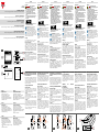 1
1
-
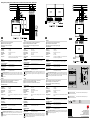 2
2
-
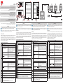 3
3
-
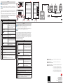 4
4
-
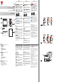 5
5
-
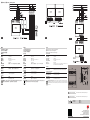 6
6
-
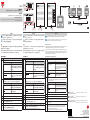 7
7


CARLO GAVAZZI ET272DINMV53X2SX Guía de instalación
- Tipo
- Guía de instalación
en otros idiomas
- français: CARLO GAVAZZI ET272DINMV53X2SX Guide d'installation
- italiano: CARLO GAVAZZI ET272DINMV53X2SX Guida d'installazione
- English: CARLO GAVAZZI ET272DINMV53X2SX Installation guide
- Deutsch: CARLO GAVAZZI ET272DINMV53X2SX Installationsanleitung
- dansk: CARLO GAVAZZI ET272DINMV53X2SX Installationsvejledning
Artículos relacionados
-
CARLO GAVAZZI VMU11000V El manual del propietario
-
-
-
-
-
-
-
-
-