Sauder Mates Bed 423003 Instrucciones de operación
- Tipo
- Instrucciones de operación

sauder.com
Mates Bed
Model 423003
NOTE: THIS INSTRUCTION
BOOKLET CONTAINS IMPORTANT
SAFETY INFORMATION.
PLEASE READ AND KEEP FOR
FUTURE REFERENCE.
English pg 1-20
Français pg 21-23
Español pg 24-26
Lot # 531291 07/17/19
Purchased: __________________
sauder.com
CONTACT US FIRST
BEFORE MAKING ANY RETURNS TO THE STORE.
Share your journey!
sauder.com
CONTACT US FIRST
BEFORE MAKING ANY RETURNS TO THE STORE.
Visit sauder.com/service to order replacement parts, view video assembly tips, or chat with a live rep.
Prefer the phone? Give us a ring at
1-800-523-3987.
Customer Service is available Monday-Friday - 9 a.m. to 5:30 p.m. EST (except holidays)
WARNING
CHOKING HAZARD - Small Parts
Not for children under 3 years.
Adult assembly required.

Hammer
Not actual size
No. 2 Phillips Screwdriver
Tip Shown Actual Size
Skip the power trip.
This time.
Table of Contents Assembly Tools Required
Part Identifi cation
Hardware Identifi cation
Assembly Steps
Français
Español
Warranty
3
4
5-20
21-23
24-26
27
423003 www.sauder.com/servicePage 2

å While not all parts are labeled, some of the parts will have a label or an inked letter on the edge
to help distinguish similar parts from each other. Use this part identifi cation to help identify similar parts.
Part Identifi cation
Now you know
our ABCs.
A2 BOTTOM (2)
B HEADBOARD/FOOTBOARD (2)
B30 DRAWER BOTTOM (2)
C BACK PANEL (1)
D CENTER SUPPORT (1)
D212 RIGHT DRAWER SIDE (2)
D213 LEFT DRAWER SIDE (2)
D476 DRAWER BACK (2)
E UPPER RAIL (1)
F LOWER RAIL (1)
G CLEAT (6)
H RIGHT DRAWER FRONT (1)
J LEFT DRAWER FRONT (1)
M65
DRAWER BRACE (2)
(Hidden part using recycled
material. Color may vary.)
A2
A2
B
B
B30
B30
C
G
G
G
G
G
G
D212
D476
D476
D212
D213
D213
M65
M65
H
J
E
F
423003www.sauder.com/service
Page 3
D

å Screws are shown actual size. You may receive extra hardware with your unit.
Hardware Identifi cation
BLACK 1-1/8" PAN HEAD SCREW - 18
9S
BLACK 9/16" LARGE HEAD SCREW - 10
1S
SILVER 1/4" MACHINE SCREW - 4
61S
SUPPORT
BRACKET - 1
11B
3S
GOLD 5/16" FLAT HEAD SCREW - 16
12E
TACK GLIDE - 12 WOOD DOWEL - 8
15F
HIDDEN CAM - 16
1F
CAM DOWEL - 16
2F
BLACK 1-1/2" FLAT HEAD SCREW - 10
101S
GLUE - 1
54M
30S
BLACK 1-9/16" FLAT HEAD SCREW - 10
BROWN PLASTIC
WASHER - 4
151M
40DA
UNIVERSAL CABINET RAIL - 4
40DC
DRAWER RIGHT - 2
40DD
DRAWER LEFT - 2
PULL - 2
149K
423003 www.sauder.com/servicePage 4
DRAWER FRONT BRACKET - 2
8G

Step 1
Look for this icon. It means a
video assembly tip is available at
www.sauder.com/service/tips
å
Assemble your unit on a carpeted fl oor or on the empty
carton to avoid scratching your unit or the fl oor.
å
Push sixteen HIDDEN CAMS (1F) into the BACK
PANEL (C), CENTER SUPPORT (D), RAILS (E and F) and
DRAWER BRACES (M65). Then, insert the metal end of a
CAM DOWEL (2F) into each HIDDEN CAM.
423003www.sauder.com/service
Page 5
C
D
E
F
M65
M65
Insert the metal end of the CAM
DOWEL into the HIDDEN CAM.
Arrow
Arrow
1F
2F
(16 used)
Do not tighten the HIDDEN CAMS in this step.

å
Fasten two UNIVERSAL CABINET RAILS* (40DA) to the
HEADBOARD/FOOTBOARDS (B) exactly as shown. Use
four GOLD 5/16" FLAT HEAD SCREWS (3S) through
holes #1 and #3.
å
*patent pending glide system
Step 2
423003 www.sauder.com/servicePage 6
VIEW THE DRAWER GLIDE VIDEO
GOLD 5/16" FLAT HEAD SCREW
(4 used in this step)
3S
Glide end
Glide end
3
2
1
1
2
3
4
4
Rounded edge
Rounded edge
A tracking label will be
on one of these surfaces.
Please do not remove.
B
B
Remember:
Righty tighty.
Lefty loosey.

å
Fasten the remaining UNIVERSAL CABINET RAILS* (40DA) to each
surface of the CENTER SUPPORT (D) exactly as shown. Use four
GOLD 5/16" FLAT HEAD SCREWS (3S) through holes #1 and #3.
å
Fasten the SUPPORT BRACKET (11B) to the CENTER SUPPORT (D).
Use two BLACK 9/16" LARGE HEAD SCREWS (1S).
å
NOTE: Position the BRACKET exactly as shown.
Step 3
423003www.sauder.com/service
Page 7
VIEW THE DRAWER GLIDE VIDEO
Glide end
Glide end
1
2
3
4
11B
1
2
3
4
D
BLACK 9/16" LARGE HEAD SCREW
(2 used in this step)
1S
GOLD 5/16" FLAT HEAD SCREW
(4 used in this step)
3S

å
With a hammer, tap twelve TACK GLIDES (12E) into the
long edges of the HEADBOARD/FOOTBOARDS (B),
BACK PANEL (C), CENTER SUPPORT (D), and
LOWER RAIL (F).
Step 4
423003 www.sauder.com/servicePage 8
Unfi nished edge
This SUPPORT
BRACKET must be here.
12E
12E
B
B
C
D
F

Step 5
423003www.sauder.com/service
Page 9
Fill the holes 1/4 to 1/2 full with GLUE.
Inspect the parts thoroughly before
assembling. Disassembly of glued
parts is extremely di cult.
Caution
!
54M
15F
15F
å
First, fi ll the center holes in the short edges of the BACK PANEL (C) 1/4
to 1/2 full with GLUE (54M). Then, insert two WOOD DOWELS (15F)
into the holes. Wipe away the excess GLUE.
å
Now, fi ll the hole in the HEADBOARD/FOOTBOARD (B) 1/4 to 1/2
full with GLUE. Fasten the HEADBOARD/FOOTBOARD (B) to the
BACK PANEL (C). Tighten two HIDDEN CAMS. Wipe away the
excess glue.
å
NOTE: Be sure the WOOD DOWEL in the BACK PANEL inserts into
the hole in the HEADBOARD/FOOTBOARD.
Surface with
HIDDEN CAMS
The CABINET RAIL
should be here.
Rounded edge
Rounded edge
B
C

Step 6
423003 www.sauder.com/servicePage 10
Fill the holes 1/4 to 1/2 full with GLUE.
Inspect the parts thoroughly before
assembling. Disassembly of glued
parts is extremely di cult.
Caution
!
54M
15F
15F
å
First, fi ll the holes in the short edges of the CENTER
SUPPORT (D) 1/4 to 1/2 full with GLUE (54M). Then,
insert two WOOD DOWELS (15F) into the holes. Wipe
away the excess GLUE.
å
Now, fi ll the center hole in the BACK PANEL (C) 1/4 to 1/2
full with GLUE. Fasten the CENTER SUPPORT (D) to the
BACK PANEL (C). Tighten two HIDDEN CAMS. Wipe away
the excess GLUE.
å
NOTE: Be sure the WOOD DOWEL in the CENTER
SUPPORT inserts into the hole in the BACK PANEL.
Surface with HIDDEN CAMS
D
C
The CABINET RAIL
should be here.

å
First, fi ll the holes in the short edges of the LOWER RAIL (F)
1/4 to 1/2 full with GLUE (54M). Then, insert two WOOD
DOWELS (15F) into the holes. Wipe away the excess GLUE.
å
Now, fi ll the hole in the HEADBOARD/FOOTBOARD (B) and
the hole closest to the fi nished edge in the back surface of
the LOWER RAIL (F) 1/4 to 1/2 full with GLUE. Fasten the
LOWER RAIL (F) to the HEADBOARD/FOOTBOARD (B) and
CENTER SUPPORT (D). Tighten two HIDDEN CAMS. Wipe
away the excess GLUE.
å
NOTE: Be sure the WOOD DOWEL in the RAIL inserts into
the hole in the HEADBOARD/FOOTBOARD.
Step 7
423003www.sauder.com/service
Page 11
D
Fill the holes 1/4 to 1/2 full with GLUE.
Inspect the parts thoroughly before
assembling. Disassembly of glued
parts is extremely di cult.
Caution
!
F
54M
15F
15F
Surface without HIDDEN CAMS
B
Tighten the HIDDEN CAM
Tighten the HIDDEN CAM
Finished edge

Step 8
423003 www.sauder.com/servicePage 12
E
15F
Rounded edge
Surface without HIDDEN CAMS
The UPPER RAIL will rest on
the SUPPORT BRACKET.
15F
å
First, fi ll the holes in the short edges of the UPPER RAIL (E)
1/4 to 1/2 full with GLUE (54M). Then, insert two WOOD
DOWELS (15F) into the holes. Wipe away the excess GLUE.
å
Now, fi ll the hole in the HEADBOARD/FOOTBOARD (B)
1/4 to 1/2 full with GLUE. Fasten the UPPER RAIL (E) to the
HEADBOARD/FOOTBOARD (B) and CENTER SUPPORT (D).
Tighten two HIDDEN CAMS. Wipe away the excess GLUE.
å
NOTE: Be sure the WOOD DOWEL in the RAIL inserts into
the hole in the HEADBOARD/FOOTBOARD.
B
Tighten the HIDDEN CAM
Tighten the HIDDEN CAM
Fill the holes 1/4 to 1/2 full with GLUE.
Inspect the parts thoroughly before
assembling. Disassembly of glued
parts is extremely di cult.
Caution
!
D
54M

Step
å
First, fi ll the holes in the remaining HEADBOARD/
FOOTBOARD (B) 1/4 to 1/2 full with GLUE (54M).
Drop glue into the exact holes shown to the right.
å
Fasten the HEADBOARD/FOOTBOARD (B) to the
BACK PANEL (C) and RAILS (E and F). Tighten fi ve
HIDDEN CAMS. Wipe away the excess GLUE.
å
NOTE: Be sure the WOOD DOWELS in the BACK
PANEL and RAILS inserts into the holes in the
HEADBOARD/FOOTBOARD.
Step 9
423003www.sauder.com/service
Page 13
E
F
54M
B
B
C
Rounded edge
Rounded edge
Fill the holes 1/4 to 1/2 full with GLUE.
Surface without holes
Surface with holes

Step
å
Fasten four CLEATS (G) to the BACK PANEL (C)
and UPPER RAIL (E). Use twelve BLACK 1-1/8" PAN
HEAD SCREWS (9S).
Step 10
423003 www.sauder.com/servicePage 14
9S
BLACK 1-1/8" PAN HEAD SCREW
(12 used in this step)
G
G
G
G
C
E

å
Fasten the remaining CLEATS (G) to the HEADBOARD/
FOOTBOARDS (B). Use six BLACK 1-1/8" PAN
HEAD SCREWS (9S).
Step 11
423003www.sauder.com/service
Page 15
9S
BLACK 1-1/8" PAN HEAD SCREW
(6 used in this step)
G
G
B
B
Don't worry. It isn't
Rome. This can be built
in a day.

Step 12
423003 www.sauder.com/servicePage 16
VIEW THE T-SLOT BOX VIDEO
1
3
2
4
Push down
å
Pull the DRAWER FRONT BRACKETS (8G) apart and slide them
into the grooves in the DRAWER SIDES (D212 and D213). You
may need to gently tap them in with a hammer.
å
NOTE: The DRAWER FRONT BRACKETS are marked "RH" and
"LH" for easy identifi cation.
å
Fasten the RIGHT DRAWER FRONT (H) to the DRAWER FRONT
BRACKETS (8G). Use four BLACK 9/16" LARGE HEAD SCREWS (1S).
å
Slide the DRAWER BOTTOM (B30) into the grooves
in the DRAWER SIDES (D212 and D213) and
RIGHT DRAWER FRONT (H).
å
Fasten the DRAWER BRACE (M65) to the RIGHT DRAWER
FRONT (H). Tighten one HIDDEN CAM.
å
Fasten the DRAWER BACK (D476) to the DRAWER
SIDES (D212 and D213) and DRAWER BRACE (M65).
Use fi ve BLACK 1-9/16" FLAT HEAD SCREWS (30S).
å
Repeat this step for the other drawer using the LEFT
DRAWER FRONT (J).
BLACK 9/16" LARGE HEAD SCREW
(8 used in this step)
1S
D212
D213
D212
D476
D213
D212
D213
H
H
Be sure the DRAWER
BOTTOM inserts into the
DRAWER FRONT groove.
Be sure the
DRAWER
BOTTOM
inserts into
the DRAWER
BACK groove.
With the palm of your hand,
tap the DRAWER BOTTOM
down into the groove.
30S
Start each screw a few turns before
completely tightening any of them.
BLACK 1-9/16" FLAT HEAD SCREW
(10 used in this step)
Unfi nished surface
Surface with
HIDDEN CAM
B30
H
M65
M65
8G
Hidden part using
recycled material.
Color may vary.

423003www.sauder.com/service
Page 17
Step 13
D213
D212
GOLD 5/16" FLAT HEAD SCREW
(8 used in this step)
3S
VIEW THE DRAWER GLIDE VIDEO
å
Fasten a DRAWER RIGHT (40DC) to the RIGHT DRAWER
SIDE (D212) and a DRAWER LEFT (40DD) to the LEFT
DRAWER SIDE (D213). Use four GOLD 5/16" FLAT HEAD
SCREWS (3S) through holes #1 and #2.
å
NOTE: The glides are not intended to rotate.
å
Fasten a PULL (149K) to the RIGHT DRAWER FRONT (H).
Use two SILVER 1/4" MACHINE SCREWS (61S) and two
BROWN PLASTIC WASHERS (151M).
å
Repeat this step for the LEFT DRAWER.
1
2
1
2
Glide end
Glide end
H
151M
149K
SILVER 1/4" MACHINE SCREW
(4 used in this step)
61S
These holes will not be used.

å
If you purchased the 422892 Headboard, assemble that
unit now. The Headboard attachment will be shown in the
422892 Headboard instruction book.
å
NOTE: The diagrams below show the 422892 Headboard
on the left or right of this Platform Bed.
Step 14
423003 www.sauder.com/servicePage 18
422892 HEADBOARD on the right
422892 HEADBOARD on the left

å
Fasten the BOTTOMS (A2) to the CLEATS (G). Use ten
BLACK 1-1/2" FLAT HEAD SCREWS (101S).
Step 15
423003www.sauder.com/service
Page 19
G
G
BLACK 1-1/2" FLAT HEAD SCREW
(10 used in this step)
101S
A2
A2
Almost time to
celebrate! With a nap.

Step 16
423003 www.sauder.com/servicePage 20
å
To insert the drawers into your unit, tip the front of the drawer down and drop the glides on the
drawer behind the glides on the unit. Lift the front of the drawer up and slide it into the unit.
å
To make adjustments to the drawer, loosen the SCREWS in the DRAWER FRONT BRACKETS,
make needed adjustments, and tighten the SCREWS.
å
This completes assembly. Clean with a damp cloth. Wipe dry.
Place the glide on the SLIDE
behind the glide on the RAIL.
J
25 lbs.
25 lbs.
H
And to celebrate, why not share your success story at Walmart.com or

LISTE DE PIÈCES
REFERENCE DESCRIPTION QUANTITÉ
LISTE DE PIÈCES
REFERENCE DESCRIPTION QUANTITÉ
NOUS SOMMES LA POUR VOUS AIDER!
Nous faisons de notre mieux pour nous assurer que votre meuble
arrive dans d’excellentes conditions. Nos représentants du service
Clientèle sont aimables et prêts à vous aider au cas où une pièce
aurait été endommagée ou manquerait (ou si vous aviez besoin
d’aide pour l’assemblage). NE RAMENEZ PAS LE MEUBLE AU
MAGASIN. Au Canada, composez ce numéro d’appel gratuit:
1-800-523-3987
Du lundi au vendredi, de 9 heures du matin à
5:30 heures du soir (horaire Côte Est)
(sauf jours fériés)
Si une pièce a besoin d’être remplacée, la pièce de remplacement
sera envoyée dans les 48 heures. (Sauf week-ends et jours fériés)
Utilisez les instructions d’assemblage en français avec les
schémas étape par étape du manuel d’instruction en anglais.
Chaque étape en français correspond à la même étape
en anglais. La pièce devant être attachée à l’élément est
représentée en gris sur les schémas de chaque étape pour plus
de précision. Comparer la “Liste de pièces” ci-dessous avec
la “PART IDENTIFICATION” du manuel en anglais pour vous
familiariser avec les pièces avant l’assemblage.
REMARQUE : CE MANUEL D’INSTRUCTIONS CONTIENT
D’IMPORTANTES INFORMATIONS RELATIVES À LA SÉCURITÉ.
À LIRE ET CONSERVER POUR TOUTE RÉFÉRENCE FUTURE.
Noter la date d’achat
de cet élément et
conserver le livret pour
future référence. Pour
contacter Sauder en
ce qui concerne cet
élément, faire référence
au numéro de lot et
numéro de modèle en
appelant notre numéro
sans frais.
Lot nº : ____________
Date de
l'achet : ____________
40DA
GLISSIÈRE D'ÉLÉMENT UNIVERSELLE
....4
40DC TIROIR DROIT ...........................................................2
40DD TIROIR GAUCHE .....................................................2
11B CONSOLE DE SUPPORT ..................................1
12E PATIN ..............................................................................12
1F EXCENTRIQUE ESCAMOTABLE .............16
2F CHEVILLE D'EXCENTRIQUE ......................16
15F CHEVILLE EN BOIS ..............................................8
8G CONSOLE DE DEVANT DE TIROIR .........2
149K POIGNÉE .......................................................................2
151M
RONDELLE EN PLASTIQUE MARRON
.....4
54M COLLE ..............................................................................1
1S VIS TÊTE LARGE 14 mm NOIRE .............10
3S VIS TÊTE PLATE 8 mm DORÉE .............. 16
9S VIS TÊTE GOUTTE DE
SUIF 28 mm NOIRE .......................................... 18
30S VIS TÊTE PLATE 40 mm NOIRE ............10
61S VIS À MÉTAUX 6 mm ARGENTÉE ...........4
101S VIS TÊTE PLATE 38 mm NOIRE .............10
A2 DESSOUS ..........................................................................2
B TÊTE DE LIT/PIED DE LIT ....................................2
B30 FOND DE TIROIR .........................................................2
C PANNEAU ARRIÈRE ....................................................1
D SUPPORT CENTRAL .................................................1
D212 CÔTÉ DROIT DE TIROIR .......................................2
D213 CÔTÉ GAUCHE DE TIROIR .................................2
D476 ARRIÈRE DE TIROIR ..................................................2
E TRAVERSE SUPÉRIEURE .......................................1
F TRAVERSE INFÉRIEURE .........................................1
G TASSEAU ...........................................................................6
H DEVANT DE TIROIR DROIT ..................................1
J DEVANT DE TIROIR GAUCHE ...........................1
M65 ENTRETOISE DE TIROIR
(Pièce cachée utilisant des matériaux
recyclés. La couleur peut varier.) ......................2
Modèle 423003
423003www.sauder.com/service
Page 21
Lit Mates

ÉTAPE 7
Attention: Examiner bien les pièces avant d'assembler. Il est
di cile de séparer des pièces une fois encollées.
Tout d'abord, remplir les trous des chants courts de la TRAVERSE
INFÉRIEURE (F) de 1/4 à 1/2 pleins de COLLE (54M). Insérer
ensuite deux CHEVILLES EN BOIS (15F) dans les trous. Nettoyer
l'excès de COLLE.
Maintenant, remplir le trou dans la TÊTE DE LIT/PIED DE LIT (B)
et le trou le plus proche du bord fi ni dans la surface arrière de la
TRAVERSE INFÉRIEURE (F) de 1/4 à 1/2 pleins de COLLE. Fixer
la TRAVERSE INFÉRIEURE (F) sur la TÊTE DE LIT/PIED DE LIT (B)
et le SUPPORT CENTRAL (D). Serrer deux EXCENTRIQUES
ESCAMOTABLES. Nettoyer l'excès de COLLE.
REMARQUE : S'assurer de bien insérer la CHEVILLE EN BOIS
située sur la TRAVERSE dans le trou dans la TÊTE DE LIT/PIED
DE LIT.
ÉTAPE 8
Attention: Examiner bien les pièces avant d'assembler. Il est
di cile de séparer des pièces une fois encollées.
Tout d'abord, remplir les trous des chants courts de la TRAVERSE
SUPÉRIEURE (E) de 1/4 à 1/2 pleins de COLLE (54M). Insérer
ensuite deux CHEVILLES EN BOIS (15F) dans les trous. Nettoyer
l'excès de COLLE.
Maintenant, remplir le trou dans la TÊTE DE LIT/PIED DE LIT (B) de
1/4 à 1/2 pleins de COLLE. Fixer la TRAVERSE SUPÉRIEURE (E) sur
la TÊTE DE LIT/PIED DE LIT (B) et le SUPPORT CENTRAL (D). Serrer
deux EXCENTRIQUES ESCAMOTABLES. Nettoyer l'excès de COLLE.
REMARQUE : S'assurer de bien insérer la CHEVILLE EN BOIS
située sur la TRAVERSE dans le trou dans la TÊTE DE LIT/PIED
DE LIT.
ÉTAPE 6
Attention: Examiner bien les pièces avant d'assembler. Il est
di cile de séparer des pièces une fois encollées.
Tout d'abord, remplir les trous des chants courts du SUPPORT
CENTRAL (D) de 1/4 à 1/2 pleins de COLLE (54M). Insérer
ensuite deux CHEVILLES EN BOIS (15F) dans les trous. Nettoyer
l'excès de COLLE.
Maintenant, remplir le trou central du PANNEAU ARRIÈRE (C)
1/4 à 1/2 pleins de COLLE. Fixer le SUPPORT CENTRAL (D)
sur le PANNEAU ARRIÈRE (C). Serrer deux EXCENTRIQUES
ESCAMOTABLES. Nettoyer l'excès de COLLE.
REMARQUE : S'assurer de bien insérer la CHEVILLE EN
BOIS située sur le SUPPORT CENTRAL dans le trou dans le
PANNEAU ARRIÈRE.
ÉTAPE 4
À l’aide d’un marteau, enfoncer douze PATINS (12E) dans les
chants longs de la TÊTE DE LIT/PIEDS DE LIT (B), du
PANNEAU ARRIÈRE (C), du SUPPORT CENTRAL (D) et de
la TRAVERSE INFÉRIEURE (F).
ÉTAPE 5
Attention: Examiner bien les pièces avant d'assembler. Il est
di cile de séparer des pièces une fois encollées.
Tout d'abord, remplir les trous centraux dans un chant court du
PANNEAU ARRIÈRE (C) de 1/4 à 1/2 pleins de COLLE (54M).
Insérer ensuite deux CHEVILLES EN BOIS (15F) dans les trous.
Nettoyer l'excès de COLLE.
Maintenant, remplir le trou dans la TÊTE DE LIT/PIED DE LIT (B)
de 1/4 à 1/2 pleins de COLLE. Fixer la TÊTE DE LIT/PIED
DE LIT (B) sur le PANNEAU ARRIÈRE (C). Serrer deux
EXCENTRIQUES ESCAMOTABLES. Nettoyer l'excès de colle.
REMARQUE : S’assurer de bien insérer la CHEVILLE EN BOIS du
PANNEAU ARRIÈRE dans le trou dans la TÊTE DE LIT/PIED DE LIT.
ÉTAPE 3
Fixer les autres GLISSIÈRES D'ÉLÉMENT UNIVERSELLES* (40DA)
sur chaque surface du SUPPORT CENTRAL (D) exactement comme
il l’est indiqué. Utiliser quatre VIS TÊTE PLATE 8 mm DORÉES (3S)
à travers les trous nº 1 et nº 3.
Fixer la CONSOLE DE SUPPORT (11B) sur le SUPPORT CENTRAL (D).
Utiliser deux VIS TÊTE LARGE 14 mm NOIRES (1S).
REMARQUE : Placer la CONSOLE exactement comme
l'indique le schéma.
ÉTAPE 2
Fixer deux GLISSIÈRES D'ÉLÉMENT UNIVERSELLES* (40DA)
sur la TÊTE DE LIT/PIEDS DE LIT (B) exactement comme il l’est
indiqué. Utiliser quatre VIS TÊTE PLATE 8 mm DORÉES (3S) à
travers les trous nº 1 et nº 3.
*système de coulisse en instance de brevet
ÉTAPE 1
Ne pas serrer les EXCENTRIQUES ESCAMOTABLES dans cette étape.
Assembler l'élément sur un sol à moquette ou sur le carton vide
pour éviter d'endommager l'élément ou le sol.
Enfoncer seize EXCENTRIQUES ESCAMOTABLES (1F) dans
le PANNEAU ARRIÈRE (C), le SUPPORT CENTRAL (D), les
TRAVERSES (E et F) et les ENTRETOISES DE TIROIR (M65).
Ensuite, insérer l'extrémité en métal de la CHEVILLE
D'EXCENTRIQUE (2F) dans chaque EXCENTRIQUE ESCAMOTABLE.
423003 www.sauder.com/servicePage 22

ÉTAPE 16
Pour insérer les tiroirs dans l’unité, incliner le devant du tiroir vers
le bas et faire tomber les coulisses du tiroir derrière les coulisses
de l’unité. Relever le devant du tiroir et l'enfi ler dans l'élément.
Pour ajuster le tiroir, desserrer les VIS dans les SUPPORTS DE
DEVANT DE TIROIR, ajuster et serrer les VIS.
Ceci complète l'assemblage.
Nettoyer avec un tissu humide. Essuyer.
ÉTAPE 15
Fixer les DESSOUS (A2) aux TASSEAUX (G). Utiliser dix VIS TÊTE
PLATE 38 mm NOIRES (101S).
ÉTAPE 14
Si on a fait l’achat de la Tête de lit n° 422892, l’assembler à
présent. L’accessoire de Tête de lit sera illustré dans le manuel
d'instructions de la Tête de lit n° 422892.
REMARQUE : Les schémas ci-dessous illustrent la Tête de lit n°
422892 sur la gauche ou la droite de ce lit plateforme.
ÉTAPE 13
Fixer un TIROIR DROIT (40DC) sur le CÔTÉ DROIT DE
TIROIR (D212) et un TIROIR GAUCHE (40DD) sur le CÔTÉ
GAUCHE DE TIROIR (D213). Utiliser quatre VIS TÊTE
PLATE 8 mm DORÉES (3S) à travers les trous nº 1 et nº 2.
REMARQUE : Les coulisses ne sont pas sensées tourner.
Fixer un BOUTON (149K) sur le DEVANT DE TIROIR DROIT (H).
Utiliser deux VIS À MÉTAUX 6 mm ARGENTÉES (61S) et deux
RONDELLES EN PLASTIQUE MARRON (151M).
Répéter cette étape pour le TIROIR GAUCHE.
ÉTAPE 12
1. Séparer les SUPPORTS DE DEVANT DE TIROIR (8G) et les
enfi ler dans les rainures des CÔTÉS DE TIROIR (D212 et D213). Il
est peut-être nécessaire de les enfoncer délicatement à l'aide
d'un marteau.
REMARQUE : Les CONSOLES DE DEVANT DE TIROIR ont
l'inscription "RH" (Droite) et l'inscription "LH" (Gauche) pour
faciliter leur identifi cation.
Fixer le DEVANT DE TIROIR DROIT (H) aux CONSOLES DE
DEVANT DE TIROIR (8G). Utiliser quatre VIS TÊTE
LARGE 14 mm NOIRES (1S).
2. Enfi ler le FOND DE TIROIR (B30) dans les rainures des CÔTÉS
DE TIROIR (D212 et D213) et du DEVANT DE TIROIR DROIT (H).
3. Fixer l’ENTRETOISE DE TIROIR (M65) au DEVANT DE TIROIR
DROIT (H). Serrer un EXCENTRIQUE ESCAMOTABLE.
4. Fixer l'ARRIÈRE DE TIROIR (D476) aux CÔTÉS DE
TIROIR (D212 et D213) et à l’ENTRETOISE DE TIROIR (M65).
Utiliser cinq VIS TÊTE PLATE 40 mm NOIRES (30S).
Répéter cette étape pour l'autre tiroir en utilisant le DEVANT DE
TIROIR GAUCHE (J).
ÉTAPE 11
Fixer les autres TASSEAUX (G) sur la TÊTE DE LIT/PIEDS DE LIT (B).
Utiliser six VIS TÊTE GOUTTE DE SUIF 28 mm NOIRES (9S).
ÉTAPE 10
Fixer quatre TASSEAUX (G) au PANNEAU ARRIÈRE (C) et à la
TRAVERSE SUPÉRIEURE (E). Utiliser douze VIS TÊTE GOUTTE
DE SUIF 28 mm NOIRES (9S).
ÉTAPE 9
Tout d'abord, remplir les trous dans l’autre TÊTE DE LIT/PIED DE
LIT (B) de 1/4 à 1/2 pleins de COLLE (54M). Mettre colle dans les
trous exacts illustrés à la droite.
Fixer la TÊTE DE LIT/PIED DE LIT (B) sur le PANNEAU
ARRIÈRE (C) et TRAVERSES (E et F). Serrer cinq EXCENTRIQUES
ESCAMOTABLES. Nettoyer l'excès de COLLE.
REMARQUE : S'assurer de bien insérer les CHEVILLES EN BOIS
situées sur le PANNEAU ARRIÈRE et TRAVERSES dans les trous
de la TÊTE DE LIT/PIED DE LIT.
423003www.sauder.com/service
Page 23

LISTA DE PARTES
ITEM DESCRIPCIÓN CANTIDAD
ESTAMOS AQUI PARA AYUDAR!
Tratamos de asegurar que su mueble llega en condición excelente.
Nuestros representantes de Servicio al Cliente son amables y
listos para ayudarle con servicio rápido y efi ciente si una parte
está defectuosa o ausente (o si necesita ayuda con el ensamblaje).
NO DEVUELVA LA UNIDAD A LA TIENDA. Llame este número sin
cargo:
1-800-523-3987
Lunes a viernes, 9:00 a.m. - 5:30 p.m.
Hora ofi cial del Este
(excepto días festivos)
Si requiere un repuesto de una parte, será enviado dentro de
48 horas (excepto los fi nes de semana y días festivos)
Use estas instrucciones de ensamblaje en español junto con las
fi guras paso-a-paso provistas en el folleto inglés. Cada paso
en español corresponde al mismo paso en inglés. Se destacan
las fi guras de cada paso con una tonalidad oscura para mostrar
precisamente cual parte se debe montar a la unidad. Compare
la “Lista de Part” abajo con la “Part Identifi cation” en el folleto en
inglés para familiarizarse con Las partes de ensamblaje.
NOTA: ESTE FOLLETO DE INSTRUCCIONES CONTIENE
INFORMACIÓN IMPORTANTE SOBRE LA SEGURIDAD. POR
FAVOR LEA Y GUÁRDELO PARA REFERENCIA EN EL FUTURO.
LISTA DE PARTES
ITEM DESCRIPCIÓN CANTIDAD
Anote la fecha de
comprar esta unidad y
guarde el folleto para
su referencia futura. Si
necesita ponerse en
contacto con Sauder en
cuanto a esta unidad,
refi érase al número
de lote y al número de
modelo cuando llame a
nuestro número gratis.
No. lote: ____________
Fecha de
compra: ____________
40DA RIEL UNIVERSAL DE GABINETE ...............4
40DC CAJÓN DERECHO ................................................2
40DD CAJÓN IZQUIERDO .............................................2
11B SOPORTE DE APOYO.........................................1
12E TACHUELA DESLIZANTE ..............................12
1F EXCÉNTRICO ESCONDIDO .......................16
2F PASADOR DE EXCÉNTRICO ...................... 16
15F PASADOR DE MADERA ....................................8
8G MÉNSULA DE CARA DE CAJÓN ...............2
149K TIRADOR .......................................................................2
151M ARANDELA DE PLÁSTICO MARRÓN ....4
54M PEGAMENTO .............................................................1
1S TORNILLO NEGRO DE CABEZA
GRANDE de 14 mm ...........................................10
3S TORNILLO DORADO DE CABEZA
PERDIDA de 8 mm .............................................16
9S TORNILLO NEGRO DE CABEZA
REDONDA de 28 mm ...................................... 18
30S TORNILLO NEGRO DE CABEZA
PERDIDA de 40 mm .........................................10
61S TORNILLO PLATEADO PARA
METAL de 6 mm .....................................................4
101S TORNILLO NEGRO DE
CABEZA PERDIDA de 38 mm ..................10
A2 FONDO ...........................................................................2
B CABECERA/PIE DE CAMA .............................2
B30 FONDO DE CAJÓN ...............................................2
C PANEL POSTERIOR ...............................................1
D SOPORTE DEL CENTRO ...................................1
D212 LADO DERECHO DE CAJÓN ........................2
D213 LADO IZQUIERDO DE CAJÓN .....................2
D476 DORSO DE CAJÓN ...............................................2
E RIEL SUPERIOR .........................................................1
F RIEL INFERIOR ...........................................................1
G LISTÓN ............................................................................6
H CARA DERECHA DE CAJÓN .........................1
J CARA IZQUIERDA DE CAJÓN ......................1
M65 RIOSTRA DE CAJÓN
(Parte oculta utilizando material
reciclado. El color puede variar.) ..................2
Modelo 423003
423003 www.sauder.com/servicePage 24
Cama Nido

PASO 8
Precaución: Revise las partes cuidadosamente antes de
ensamblar. La separación de las piezas ya pegadas es muy difícil.
Primero, llene los agujeros de los bordes cortos del RIEL
SUPERIOR (E) entre 1/4 a 1/2 con PEGAMENTO (54M). A
continuación, inserte dos PASADORES DE MADERA (15F) dentro
de los agujeros. Quite el exceso de PEGAMENTO.
Ahora, llene los agujeros de la CABECERA / del PIE DE CAMA (B) entre
1/4 a 1/2 con PEGAMENTO. Fije el RIEL SUPERIOR (E) a la CABECERA
/ al PIE DE CAMA (B) y al SOPORTE DEL CENTRO (D). Apriete dos
EXCÉNTRICOS ESCONDIDOS. Quite el exceso de PEGAMENTO.
NOTA: Asegúrese de que el PASADOR DE MADERA sujetado al
RIEL se inserte en el agujero de la CABECERA / del PIE DE CAMA.
PASO 7
Precaución: Revise las partes cuidadosamente antes de
ensamblar. La separación de las piezas ya pegadas es muy difícil.
Primero, llene los agujeros de los bordes cortos del RIEL
INFERIOR (F) entre 1/4 a 1/2 con PEGAMENTO (54M). A
continuación, inserte dos PASADORES DE MADERA (15F) dentro
de los agujeros. Quite el exceso de PEGAMENTO.
Ahora, llene el agujero en la CABECERA / el PIE DE CAMA (B) y
el agujero más cercano del borde con acabado en la superfi cie
posterior del RIEL INFERIOR (F) entre 1/4 a 1/2 con PEGAMENTO.
Fije el RIEL INFERIOR (F) a la CABECERA / al PIE DE CAMA (B)
y al SOPORTE DEL CENTRO (D). Apriete dos EXCÉNTRICOS
ESCONDIDOS. Quite el exceso de PEGAMENTO.
NOTA: Asegúrese de que el PASADOR DE MADERA sujetado al
RIEL se inserte en el agujero de la CABECERA / del PIE DE CAMA.
PASO 6
Precaución: Revise las partes cuidadosamente antes de
ensamblar. La separación de las piezas ya pegadas es muy difícil.
Primero, llene los agujeros de los bordes cortos del SOPORTE
DEL CENTRO (D) entre 1/4 a 1/2 con PEGAMENTO (54M). A
continuación, inserte dos PASADORES DE MADERA (15F) dentro
de los agujeros. Quite el exceso de PEGAMENTO.
Ahora, llene el agujero central en el PANEL POSTERIOR (C) entre
1/4 y 1/2 con PEGAMENTO. Fije el SOPORTE DEL CENTRO (D) al
PANEL POSTERIOR (C). Apriete dos EXCÉNTRICOS ESCONDIDOS.
Quite el exceso de PEGAMENTO.
NOTA: Asegúrese de que el PASADOR DE MADERA sujetado al
SOPORTE DEL CENTRO se inserte en el agujero del PANEL POSTERIOR
PASO 4
Utilizando un martillo, ligeramente golpee doce TACHUELAS
DESLIZANTES (12E) en los bordes largos de las CABECERAS /
los PIES DE CAMA (B), el PANEL POSTERIOR (C), el SOPORTE
DEL CENTRO (D) y el RIEL INFERIOR (F).
PASO 5
Precaución: Revise las partes cuidadosamente antes de
ensamblar. La separación de las piezas ya pegadas es muy difícil.
Primero, llene los agujeros centrales de los bordes cortos del
PANEL POSTERIOR (C) entre 1/4 a 1/2 con PEGAMENTO (54M).
A continuación, inserte dos PASADORES DE MADERA (15F)
dentro de los agujeros. Quite el exceso de PEGAMENTO.
Ahora, llene los agujeros de la CABECERA / del PIE DE CAMA (B)
entre 1/4 a 1/2 con PEGAMENTO. Fije la CABECERA / el PIE DE
CAMA (B) al PANEL POSTERIOR (C). Apriete dos EXCÉNTRICOS
ESCONDIDOS. Quite el exceso de pegamento.
NOTA: Asegúrese de insertar el PASADOR DE MADERA del PANEL
POSTERIOR en el agujero de la CABECERA / del PIE DE CAMA.
PASO 3
Fije los otros RIELES UNIVERSALES DE GABINETE* (40DA) a cada
superfi cie del SOPORTE DEL CENTRO (D) exactamente como
se muestra. Utilice cuatro TORNILLOS DORADOS DE CABEZA
PERDIDA de 8 mm (3S) a través de los agujeros No. 1 y No. 3.
Fije el SOPORTE DE APOYO (11B) al SOPORTE DEL CENTRO (D).
Utilice dos TORNILLOS NEGROS DE CABEZA GRANDE de 14 mm (1S).
NOTA: Coloque el SOPORTE exactamente como se muestra.
PASO 2
Fije dos RIELES UNIVERSALES DE GABINETE* (40DA) a las
CABECERAS / los PIES DE CAMA (B) exactamente como se
muestra. Utilice cuatro TORNILLOS DORADOS DE CABEZA
PERDIDA de 8 mm (3S) a través de los agujeros No. 1 y No. 3.
*La patente del sistema de deslizamiento se encuentra en trámite.
PASO 1
No apriete los EXCÉNTRICOS ESCONDIDOS en este paso.
Ensamble la unidad sobre un piso alfombrado o sobre el cartón
vacío para evitar rayar la unidad o el piso.
Empuje dieciséis EXCÉNTRICOS ESCONDIDOS (1F) en el
PANEL POSTERIOR (C), al SOPORTE DEL CENTRO (D), a
los RIELES (E y F) y a las RIOSTRAS DE CAJÓN (M65). A
continuación, inserte el extremo de metal de un PASADOR DE
EXCÉNTRICO (2F) dentro de cada EXCÉNTRICO ESCONDIDO.
423003www.sauder.com/service
Page 25

PASO 13
Fije un CAJÓN DERECHO (40DC) al LADO DERECHO DE
CAJÓN (D212) y un CAJÓN IZQUIERDO (40DD) al LADO
IZQUIERDO DE CAJÓN (D213). Utilice cuatro TORNILLOS
DORADOS DE CABEZA PERDIDA de 8 mm (3S) a través de los
agujeros No. 1 y No. 2.
NOTA: Los corrimientos no están concebidos para rotar.
Fije un TIRADOR (149K) a la CARA DERECHA DE CAJÓN (H).
Utilice dos TORNILLOS PLATEADOS DE METAL de 6 mm (61S) y
dos ARANDELAS DE PLÁSTICO MARRÓN (151M).
Repita este paso para el CAJÓN IZQUIERDO.
PASO 14
Si usted compró la Cabecera 422892, ensámblela ahora. La
fi jación de la Cabecera se mostrará en el manual de Instrucción
de la Cabecera 422892.
NOTA: Los diagramas a continuación muestran la Cabecera
422892 a la izquierda o a la derecha de esta Cama de plataforma.
PASO 15
Fije los FONDOS (A2) a los LISTONES (G). Utilice diez
TORNILLOS NEGROS DE CABEZA PERDIDA de 38 mm (101S).
PASO 16
Para insertar los cajones en la unidad, incline la parte delantera
del cajón hacia abajo y deje que los corrimientos del cajón caigan
detrás de los corrimientos de la unidad. Levante la parte delantera
del cajón y deslícelo dentro de la unidad.
Para ajustar el cajón, afl oje los TORNILLOS de las MÉNSULAS
DE CARA DE CAJÓN, haga los ajustes necesarios y apriete los
TORNILLOS.
Esto completa el ensamblaje. Limpiar con un trapo húmedo.
Seque con un paño.
PASO 12
1. Separe las MÉNSULAS DE CARA DE CAJÓN (8G) y deslícelas
dentro de las ranuras de los LADOS DE CAJÓN (D212 y D213). Puede
ser necesario que las clave ligeramente adentro con un martillo.
NOTA: Las MÉNSULAS DE CARA DE CAJÓN tienen una
inscripción "RH" (derecha) y una inscripción "LH" (izquierda) para
identifi carlas fácilmente.
Fije la CARA DERECHA DE CAJÓN (H) a las MÉNSULAS DE
CARA DE CAJÓN (8G). Utilice cuatro TORNILLOS NEGROS DE
CABEZA GRANDE de 14 mm (1S).
2. Deslice el FONDO DE CAJÓN (B30) en las ranuras de los
LADOS DE CAJÓN (D212 y D213) y de la CARA DERECHA
DE CAJÓN (H).
3. Fije la RIOSTRA DE CAJÓN (M65) a la CARA DERECHA DE
CAJÓN (H). Apriete un EXCÉNTRICO ESCONDIDO.
4 Fije el DORSO DE CAJÓN (D476) a los LADOS DE CAJÓN (D212
y D213) y a la RIOSTRA DE CAJÓN (M65). Utilice cinco TORNILLOS
NEGROS DE CABEZA PERDIDA de 40 mm (30S).
Repita este paso para el otro cajón utilizando la CARA IZQUIERDA
DE CAJÓN (J).
PASO 11
Fije los otros LISTONES (G) a la CABECERA / al PIE DE
CAMA (B). Utilice seis TORNILLOS NEGROS DE CABEZA
REDONDA de 28 mm (9S).
PASO 10
Fije cuatro LISTONES (G) al PANEL POSTERIOR (C) y al RIEL
SUPERIOR (E). Utilice doce TORNILLOS NEGROS DE CABEZA
REDONDA de 28 mm (9S).
PASO 9
Primero, llene los agujeros en la otra CABECERA / otro PIE DE
CAMA (B) entre 1/4 a 1/2 con PEGAMENTO (54M). Coloque
pegamento en los agujeros correspondientes indicados que se
muestran a la derecha.
Fije la CABECERA / el PIE DE CAMA (B) al PANEL
POSTERIOR (C) y a los RIELES (E y F). Apriete cinco
EXCÉNTRICOS ESCONDIDOS. Quite el exceso de PEGAMENTO.
NOTA: Asegúrese de que los PASADORES DE MADERA sujetados
al PANEL POSTERIOR y RIELES se inserten en los agujeros de la
CABECERA / del PIE DE CAMA.
423003 www.sauder.com/servicePage 26

423003www.sauder.com/service
Page 27
1. Sauder Woodworking Co. (Sauder®) provee cobertura de garantía limitada al
comprador original de este producto por un período de un año, a partir de la fecha de
compra, contra defectos en los materiales o de mano de obra en los componentes de
muebles Sauder. Como es utilizado en esta Garantía, “defecto” signifi ca imperfecciones
en los componentes que de manera fundamental afecta la utilidad del producto. Esta
Garantía le permite a usted ciertos derechos legales, y usted también podría poseer
otros derechos adicionales, los cuales varían de estado a estado.
2. No hay cobertura de garantía para defectos o estados que resulten del
incumplimiento en seguir las instrucciones, la información o las advertencias sobre el
ensamblaje del producto; del uso incorrecto o maltrato, del daño intencional, incendio,
inundación, cambio o modifi cación del producto; o de la utilización del producto de
manera contradictoria con el uso para el cual fue fabricado, ni por ningún estado que
resulte del mantenimiento, limpieza o cuidado incorrecto o inadecuado. Tampoco no
hay cobertura de garantía para los productos rentados o para cualesquiera productos
comprados “de uso” o “como está”, en una venta de bienes embargados o en una
venta por salirse del negocio, o comprados a un liquidador.
3. Como un recurso exclusivo bajo esta Garantía, Sauder (sólo a su opción) reparará,
reemplazará o reembolsará el valor de cualquier componente defectuoso de mueble.
Sauder puede requerir una confi rmación independiente de un defecto reclamado y una
prueba de compra. Las piezas de repuesto serán garantizadas solamente por el período
de tiempo que queda de la Garantía original. SAUDER NO TENDRÁ RESPONSABILIDAD
por NINGÚN DAÑO INCIDENTAL O CONSECUENTE DE NINGÚN TIPO y todos dichos
daños SE EXCLUYEN DE ESTA GARANTÍA, tales como pérdida de uso, desensamblaje,
transportación, trabajo o daño a la propiedad en o cerca del producto. Algunos estados
no permiten la exclusión o limitación de daños incidentales o consecuentes, en tales
instancias la limitación o exclusión antes mencionada podría no ser aplicable a usted.
4. Esta Garantía sólo es aplicable a defectos garantizados que primeramente surjan
y se informen a Sauder dentro del período de cobertura de garantía. La Garantía
no puede ser transferida a propietarios o usuarios subsiguientes del producto, y
ésta será inmediatamente invalidada en el caso que el producto sea revendido,
transferido, arrendado o rentado a cualquier tercero u otra persona que no sea el
comprador original.
5. NO HAY OTRA GARANTÍA APLICABLE A ESTE PRODUCTO. Bajo las leyes
de ciertos estados, pueden no haber garantías implícitas de Sauder y se hace
renuncia de responsabilidad de todas las garantías implícitas donde lo permita la
ley, INCLUYENDO CUALQUIER GARANTÍA IMPLÍCITA DE MERCANTIBILIDAD O
DE APTITUD PARA UN PROPÓSITO EN PARTICULAR. EN LA MEDIDA CUALQUIER
GARANTÍA IMPLÍCITA ES APLICABLE, CUALESQUIERA GARANTÍAS IMPLÍCITAS,
INCLUYENDO AQUELLA DE MERCANTIBILIDAD O DE APTITUD PARA UN
PROPÓSITO EN PARTICULAR, SE LIMITAN EN DURACIÓN HASTA LA DURACIÓN
DE ESTA GARANTÍA IMPLÍCITA o hasta el periodo mínimo permitido por la ley,
la que sea más corta. Algunos estados no permiten limitaciones en cuanto a la
duración de una garantía implícita, por eso la limitación arriba citada pueda no ser
aplicable a usted.
6. Para solicitud de información o reclamación de Garantía, por favor, visite nuestro
sitio Web www.sauder.com. Usted también puede contactar a Sauder llamando al
1.800.523.3987. Sauder puede solicitar que las reclamaciones sean presentadas por
escrito a: Sauder Woodworking Co., 502 Middle Street, Archbold, OH 43502 USA.
Por favor incluya su recibo de venta u otra prueba de compra y una descripción
detallada del defecto del producto.
GARANTÍA LIMITADA DE 1 AÑO
1. Sauder Woodworking Co. (Sauder®) o re une couverture de garantie limitée à l'acheteur
initial du présent produit pendant une période de un an à compter de la date d'achat
contre tout défaut de matériaux ou de fabrication des composantes de mobilier Sauder.
Le mot « défaut », tel qu’il est utilisé sous les termes de la présente garantie, comprend
les imperfections des pièces qui empêchent substantiellement l’utilisation du produit. La
présente garantie vous donne des droits légaux spécifi ques et il est possible que vous
ayez des droits supplémentaires variant d’État en État ou de province en province.
2. La présente garantie ne saurait couvrir les défauts ou conditions qui surviendraient
à la suite du non respect des instructions, informations ou mises en garde de
montage, d’une mauvaise utilisation ou d’un abus, d’un dommage intentionnel, d’un
incendie, d’une inondation, d’une altération ou modifi cation du produit, d’une utilisation
du produit allant à l’encontre de son usage prévu, ni aucune condition résultant d'une
maintenance, d'un nettoyage ou d'un entretien inappropriés ou inadéquats. De plus,
il n'existe aucune garantie pour les produits loués ou tous les produits achetés «
d'occasion » ou « en l'état », dans le cadre d'une vente aux enchères ou de solde
pour cessation de commerce, ou auprès d'un liquidateur.
3. En tant que recours exclusif en vertu de la présente garantie, Sauder réparera,
remplacera ou rembourser (sur sa seule décision) la valeur de toute composante de
mobilier défectueuse. Sauder peut exiger une confi rmation indépendante du défaut
revendiqué ainsi qu'une preuve d'achat. Les pièces de rechange seront garanties
uniquement pendant la période restante de la garantie originale. SAUDER NE SERA EN
AUCUN CAS RESPONSABLE de TOUT DOMMAGE ACCESSOIRE OU CONSÉCUTIF
DE TOUTE SORTE et lesdits dommages sont EXCLUS DE LA PRÉSENTE GARANTIE,
à savoir perte d'utilisation, démontage, transport, main d'œuvre ou dommages
matériels sur ou à proximité du produit. Certains États ou provinces ne permettant pas
l’exclusion ou la limite aux responsabilités pour dommages accidentels ou consécutifs,
la limite ou l’exclusion ci -dessus peut ne pas être applicable.
4. La présente garantie ne s'applique qu'aux défauts garantis qui se produisent pour
la première fois et qui sont signalés à Sauder dans les limites de couverture de la
garantie. La garantie ne peut pas être transférée à des propriétaires ou utilisateurs
subséquents du produit, et sera immédiatement invalidée dans le cas où le produit
est revendu, transféré, loué sous bail ou loué à une tierce partie ou personne autre
que l’acheteur original.
5. IL N'EXISTE AUCUNE AUTRE GARANTIE EN VIGUEUR POUR LE PRÉSENT
PRODUIT. En vertu des lois de certains États ou provinces, il ne peut y avoir
de garanties implicites de la part de Sauder et toutes les garanties implicites,
Y COMPRIS TOUTE GARANTIE IMPLICITE DE COMMERCIABILITÉ OU
D'ADAPTATION À UN USAGE PARTICULIER sont déclinées partout où la
loi l'autorise. DANS LA MESURE OÙ TOUTE GARANTIE IMPLICITE EST
APPLICABLE, TOUTE GARANTIE IMPLICITE, Y COMPRIS TOUTE GARANTIE
DE COMMERCIABILITÉ OU D'ADAPTATION À UN USAGE PARTICULIER, EST
LIMITÉE À LA DURÉE DE LA PRÉSENTE GARANTIE EXPRESSE ou à la période
minimum autorisée par la loi, la période la plus courte étant retenue. Certains États
ne permettant pas que des limites soient imposées quant à la durée d’une garantie
implicite, la limite ci-dessus peut donc ne pas être applicable.
6. Pour toute question concernant la garantie ou toute demande de réclamation,
consulter le site Web www.sauder.com. Il est également possible de contacter Sauder
en composant le 1.800.523.3987. Sauder peut exiger de soumettre les demandes de
réclamation sous garantie par écrit à : Sauder Woodworking Co., 502 Middle Street,
Archbold, OH 43502 USA. Veuillez joindre votre ticket de caisse ou toute autre
preuve d’achat ainsi qu’une description spécifi que du défaut de produit.
GARANTIE LIMITÉE DE 1 AN
1. Sauder Woodworking Co. (Sauder®) provides limited warranty coverage to the
original purchaser of this product for a period of one year from the date of purchase
against defects in materials or workmanship of Sauder furniture components.
As used in this Warranty, “defect” means imperfections in components which
substantially impair the utility of the product. This Warranty gives you specifi c legal
rights, and you may also have other rights which vary from state to state.
2. There is no warranty coverage for defects or conditions that result from the failure
to follow product assembly instructions, information or warnings, misuse or abuse,
intentional damage, fi re, fl ood, alteration or modifi cation of the product, or use of the
product in a manner inconsistent with its intended use, nor any condition resulting
from incorrect or inadequate maintenance, cleaning, or care. There is also no
warranty coverage for rented products or any products purchased “used” or “as is”, at
a distress or going-out-of business sale, or from a liquidator.
3. As the exclusive remedy under this Warranty, Sauder will (at its sole option) repair,
replace or refund the value of any defective furniture component. Sauder may require
independent confi rmation of the claimed defect and proof of purchase. Replacement
parts will be warranted for only the remaining period of the original Warranty. SAUDER
SHALL HAVE NO LIABILITY for ANY INCIDENTAL OR CONSEQUENTIAL DAMAGES
OF ANY KIND and all such damages are EXCLUDED FROM THIS WARRANTY, such
as loss of use, disassembly, transportation, labor or damage to property on or near
the product. Some states do not allow the exclusion or limitation of incidental or
consequential damages, so the above limitation or exclusion may not apply to you.
4. This Warranty applies only to warranted defects that fi rst arise and are reported to
Sauder within the warranty coverage period. The Warranty cannot be transferred to
subsequent owners or users of the product, and it shall be immediately void in the
event the product is resold, transferred, leased or rented to any third party or person
other than the original purchaser.
5. THERE ARE NO OTHER WARRANTIES APPLICABLE TO THIS PRODUCT. Under
the laws of certain states, there may be no implied warranties from Sauder and all
implied warranties, INCLUDING ANY IMPLIED WARRANTY OF MERCHANTABILITY
OR FITNESS FOR A PARTICULAR PURPOSE are disclaimed where allowed by law.
TO THE EXTENT ANY IMPLIED WARRANTIES ARE APPLICABLE, ANY IMPLIED
WARRANTIES, INCLUDING ANY IMPLIED WARRANTY OF MERCHANTABILITY OR
FITNESS FOR A PARTICULAR PURPOSE, ARE LIMITED IN DURATION TO THE
DURATION OF THIS EXPRESS WARRANTY or the minimum period allowed by law,
whichever is shorter. Some states do not allow limitations on how long an implied
Warranty lasts, so the above limitation may not apply to you.
6. For Warranty inquiries or claims, please visit our website www.sauder.com. You
can also contact Sauder at 1.800.523.3987. Sauder may require Warranty claims to
be submitted in writing to: Sauder Woodworking Co., 502 Middle Street, Archbold,
OH 43502 USA. Please include your sales receipt or other proof of purchase and a
specifi c description of the product defect.
1-YEAR LIMITED WARRANTY

General Conformity Certifi cate
1. This certifi cate applies to the Sauder Woodworking
Product identifi ed by this Instruction Book.
2. This certifi cate applies to compliance of this
product with the CPSC Ban on Lead-Containing
Paint (16 CFR 1303).
3. This product is manufactured by:
Sauder Woodworking Company
502 Middle St.
Archbold, OH 43502
419-446-2711
4. Date of Manufacture: __________________________
So, how did it go?
Set a world record for speed?
Feeling good about yourself?
Nice. Get social with it on any of these
quality share sites.
And don’t forget to rate
and review your piece at Walmart.com
in the product detail page.
If you need assistance please contact customer service at 800-523-3987 Monday-Friday - 9 a.m. to
5:30 p.m. EST (except holidays) or at
sauder.com/service.
Register your new
product online
For immediate service, 24 hours per day, 7 days per
week, to order replacement parts, access assembly tips
and register your product, visit www.sauder.com/service
Transcripción de documentos
CONTACT US FIRST sauder.com BEFORE MAKING ANY RETURNS TO THE STORE. Visit sauder.com/service to order replacement parts, view video assembly tips, or chat with a live rep. Prefer the phone? Give us a ring at 1-800-523-3987. Customer Service is available Monday-Friday - 9 a.m. to 5:30 p.m. EST (except holidays) WARNING CHOKING HAZARD - Small Parts Not for children under 3 years. Adult assembly required. Mates Bed Model 423003 NOTE: THIS INSTRUCTION BOOKLET CONTAINS IMPORTANT SAFETY INFORMATION. PLEASE READ AND KEEP FOR FUTURE REFERENCE. English pg 1-20 Français pg 21-23 Español pg 24-26 Share your journey! Lot # 531291 07/17/19 Purchased: __________________ Table of Contents Part Identification Hardware Identification Assembly Steps Assembly Tools Required 3 No. 2 Phillips Screwdriver Tip Shown Actual Size 4 5-20 Hammer Français 21-23 Español 24-26 Warranty Page 2 Not actual size Skip the power trip. This time. 27 423003 www.sauder.com/service Now you know our ABCs. Part Identification å While not all parts are labeled, some of the parts will have a label or an inked letter on the edge to help distinguish similar parts from each other. Use this part identification to help identify similar parts. A2 BOTTOM (2) D212 RIGHT DRAWER SIDE (2) G CLEAT (6) B HEADBOARD/FOOTBOARD (2) D213 LEFT DRAWER SIDE (2) H RIGHT DRAWER FRONT (1) DRAWER BOTTOM (2) D476 DRAWER BACK (2) J LEFT DRAWER FRONT (1) M65 DRAWER BRACE (2) (Hidden part using recycled material. Color may vary.) B30 C BACK PANEL (1) E UPPER RAIL (1) D CENTER SUPPORT (1) F LOWER RAIL (1) A2 A2 G B G C G G D E G D212 D476 F G B30 H B D213 M65 D212 D476 B30 J D213 www.sauder.com/service M65 423003 Page 3 Hardware Identification å Screws are shown actual size. You may receive extra hardware with your unit. 40DA UNIVERSAL CABINET RAIL - 4 40DC DRAWER RIGHT - 2 12E TACK GLIDE - 12 HIDDEN CAM - 16 1F 8G DRAWER FRONT BRACKET - 2 149K 1S BLACK 9/16" LARGE HEAD SCREW - 10 9S BLACK 1-1/8" PAN HEAD SCREW - 18 2F PULL - 2 CAM DOWEL - 16 151M 3S 11B SUPPORT BRACKET - 1 15F WOOD DOWEL - 8 BROWN PLASTIC WASHER - 4 54M GLUE - 1 GOLD 5/16" FLAT HEAD SCREW - 16 30S BLACK 1-9/16" FLAT HEAD SCREW - 10 61S SILVER 1/4" MACHINE SCREW - 4 Page 4 40DD DRAWER LEFT - 2 101S 423003 BLACK 1-1/2" FLAT HEAD SCREW - 10 www.sauder.com/service Look for this icon. It means a video assembly tip is available at www.sauder.com/service/tips Step 1 å Assemble your unit on a carpeted floor or on the empty carton to avoid scratching your unit or the floor. å Push sixteen HIDDEN CAMS (1F) into the BACK PANEL (C), CENTER SUPPORT (D), RAILS (E and F) and DRAWER BRACES (M65). Then, insert the metal end of a CAM DOWEL (2F) into each HIDDEN CAM. 2F Arrow Do not tighten the HIDDEN CAMS in this step. (16 used) 1F C F E D Arrow M65 M65 Insert the metal end of the CAM DOWEL into the HIDDEN CAM. www.sauder.com/service 423003 Page 5 Step 2 VIEW THE DRAWER GLIDE VIDEO å Fasten two UNIVERSAL CABINET RAILS* (40DA) to the HEADBOARD/FOOTBOARDS (B) exactly as shown. Use four GOLD 5/16" FLAT HEAD SCREWS (3S) through holes #1 and #3. å *patent pending glide system Remember: Righty tighty. Lefty loosey. 3S GOLD 5/16" FLAT HEAD SCREW (4 used in this step) A tracking label will be on one of these surfaces. Please do not remove. Glide end 1 4 2 3 B 3 2 4 1 Glide end B Rounded edge Page 6 Rounded edge 423003 www.sauder.com/service Step 3 VIEW THE DRAWER GLIDE VIDEO å Fasten the remaining UNIVERSAL CABINET RAILS* (40DA) to each surface of the CENTER SUPPORT (D) exactly as shown. Use four GOLD 5/16" FLAT HEAD SCREWS (3S) through holes #1 and #3. å Fasten the SUPPORT BRACKET (11B) to the CENTER SUPPORT (D). Use two BLACK 9/16" LARGE HEAD SCREWS (1S). å NOTE: Position the BRACKET exactly as shown. 1S 11B BLACK 9/16" LARGE HEAD SCREW (2 used in this step) Glide end 3S 1 GOLD 5/16" FLAT HEAD SCREW (4 used in this step) 2 3 4 Glide end 1 D 2 3 4 www.sauder.com/service 423003 Page 7 Step 4 å With a hammer, tap twelve TACK GLIDES (12E) into the long edges of the HEADBOARD/FOOTBOARDS (B), BACK PANEL (C), CENTER SUPPORT (D), and LOWER RAIL (F). C 12E F This SUPPORT BRACKET must be here. B B D Unfinished edge 12E Page 8 423003 www.sauder.com/service Step 5 å First, fill the center holes in the short edges of the BACK PANEL (C) 1/4 to 1/2 full with GLUE (54M). Then, insert two WOOD DOWELS (15F) into the holes. Wipe away the excess GLUE. å Now, fill the hole in the HEADBOARD/FOOTBOARD (B) 1/4 to 1/2 full with GLUE. Fasten the HEADBOARD/FOOTBOARD (B) to the BACK PANEL (C). Tighten two HIDDEN CAMS. Wipe away the excess glue. å NOTE: Be sure the WOOD DOWEL in the BACK PANEL inserts into the hole in the HEADBOARD/FOOTBOARD. ! Caution Fill the holes 1/4 to 1/2 full with GLUE. 54M Inspect the parts thoroughly before assembling. Disassembly of glued parts is extremely difficult. 15F Rounded edge B Rounded edge ith e w AMS c a f Sur DEN C D HI 15F The CABINET RAIL should be here. C www.sauder.com/service 423003 Page 9 Step 6 å First, fill the holes in the short edges of the CENTER SUPPORT (D) 1/4 to 1/2 full with GLUE (54M). Then, insert two WOOD DOWELS (15F) into the holes. Wipe away the excess GLUE. å Now, fill the center hole in the BACK PANEL (C) 1/4 to 1/2 full with GLUE. Fasten the CENTER SUPPORT (D) to the BACK PANEL (C). Tighten two HIDDEN CAMS. Wipe away the excess GLUE. å NOTE: Be sure the WOOD DOWEL in the CENTER SUPPORT inserts into the hole in the BACK PANEL. Fill the holes 1/4 to 1/2 full with GLUE. ! Caution Inspect the parts thoroughly before assembling. Disassembly of glued parts is extremely difficult. 54M 15F C Sur fac ew ith HID DEN CA MS D 15F The CABINET RAIL should be here. Page 10 423003 www.sauder.com/service Step 7 å First, fill the holes in the short edges of the LOWER RAIL (F) 1/4 to 1/2 full with GLUE (54M). Then, insert two WOOD DOWELS (15F) into the holes. Wipe away the excess GLUE. å Now, fill the hole in the HEADBOARD/FOOTBOARD (B) and the hole closest to the finished edge in the back surface of the LOWER RAIL (F) 1/4 to 1/2 full with GLUE. Fasten the LOWER RAIL (F) to the HEADBOARD/FOOTBOARD (B) and CENTER SUPPORT (D). Tighten two HIDDEN CAMS. Wipe away the excess GLUE. å NOTE: Be sure the WOOD DOWEL in the RAIL inserts into the hole in the HEADBOARD/FOOTBOARD. Fill the holes 1/4 to 1/2 full with GLUE. ! Caution Inspect the parts thoroughly before assembling. Disassembly of glued parts is extremely difficult. B Tighten the HIDDEN CAM D Finished edge 15F Tighten the HIDDEN CAM out h t i ew fac r u S 54M MS CA N DE HID F 15F www.sauder.com/service 423003 Page 11 Step 8 å First, fill the holes in the short edges of the UPPER RAIL (E) 1/4 to 1/2 full with GLUE (54M). Then, insert two WOOD DOWELS (15F) into the holes. Wipe away the excess GLUE. å Now, fill the hole in the HEADBOARD/FOOTBOARD (B) 1/4 to 1/2 full with GLUE. Fasten the UPPER RAIL (E) to the HEADBOARD/FOOTBOARD (B) and CENTER SUPPORT (D). Tighten two HIDDEN CAMS. Wipe away the excess GLUE. å NOTE: Be sure the WOOD DOWEL in the RAIL inserts into the hole in the HEADBOARD/FOOTBOARD. Fill the holes 1/4 to 1/2 full with GLUE. ! Caution Inspect the parts thoroughly before assembling. Disassembly of glued parts is extremely difficult. 15F B Tighten the HIDDEN CAM The UPPER RAIL will rest on the SUPPORT BRACKET. D Tighten the HIDDEN CAM ut itho w e fac Sur Rounded edge S AM C DEN HID E 15F 54M Page 12 423003 www.sauder.com/service Step 9 å First, fill the holes in the remaining HEADBOARD/ FOOTBOARD (B) 1/4 to 1/2 full with GLUE (54M). Drop glue into the exact holes shown to the right. å Fasten the HEADBOARD/FOOTBOARD (B) to the BACK PANEL (C) and RAILS (E and F). Tighten five HIDDEN CAMS. Wipe away the excess GLUE. å NOTE: Be sure the WOOD DOWELS in the BACK PANEL and RAILS inserts into the holes in the HEADBOARD/FOOTBOARD. 54M Sur B fac ew ith hol es Rounded edge Fill the holes 1/4 to 1/2 full with GLUE. C Rounded edge Sur B fac ew itho ut h ole s www.sauder.com/service E F 423003 Page 13 Step 10 å Fasten four CLEATS (G) to the BACK PANEL (C) and UPPER RAIL (E). Use twelve BLACK 1-1/8" PAN HEAD SCREWS (9S). 9S BLACK 1-1/8" PAN HEAD SCREW (12 used in this step) G C G G G Page 14 E 423003 www.sauder.com/service Step 11 å Fasten the remaining CLEATS (G) to the HEADBOARD/ FOOTBOARDS (B). Use six BLACK 1-1/8" PAN HEAD SCREWS (9S). Don't worry. It isn't Rome. This can be built in a day. 9S BLACK 1-1/8" PAN HEAD SCREW (6 used in this step) G B G B www.sauder.com/service 423003 Page 15 Step 12 VIEW THE T-SLOT BOX VIDEO Push down 1 2 With the palm of your hand, tap the DRAWER BOTTOM down into the groove. 8G B30 H D213 D212 Unfi nish ed sur fac e H 1S D212 D213 BLACK 9/16" LARGE HEAD SCREW (8 used in this step) å Pull the DRAWER FRONT BRACKETS (8G) apart and slide them into the grooves in the DRAWER SIDES (D212 and D213). You may need to gently tap them in with a hammer. å NOTE: The DRAWER FRONT BRACKETS are marked "RH" and "LH" for easy identification. å Fasten the RIGHT DRAWER FRONT (H) to the DRAWER FRONT BRACKETS (8G). Use four BLACK 9/16" LARGE HEAD SCREWS (1S). 3 Be sure the DRAWER BOTTOM inserts into the DRAWER FRONT groove. å Slide the DRAWER BOTTOM (B30) into the grooves in the DRAWER SIDES (D212 and D213) and RIGHT DRAWER FRONT (H). 4 Hidden part using recycled material. Color may vary. Start each screw a few turns before completely tightening any of them. 30S BLACK 1-9/16" FLAT HEAD SCREW (10 used in this step) M65 D212 Surface with HIDDEN CAM D476 M65 H D213 å Fasten the DRAWER BRACE (M65) to the RIGHT DRAWER FRONT (H). Tighten one HIDDEN CAM. Page 16 Be sure the DRAWER BOTTOM inserts into the DRAWER BACK groove. å Fasten the DRAWER BACK (D476) to the DRAWER SIDES (D212 and D213) and DRAWER BRACE (M65). Use five BLACK 1-9/16" FLAT HEAD SCREWS (30S). å Repeat this step for the other drawer using the LEFT DRAWER FRONT (J). 423003 www.sauder.com/service Step 13 VIEW THE DRAWER GLIDE VIDEO å Fasten a DRAWER RIGHT (40DC) to the RIGHT DRAWER SIDE (D212) and a DRAWER LEFT (40DD) to the LEFT DRAWER SIDE (D213). Use four GOLD 5/16" FLAT HEAD SCREWS (3S) through holes #1 and #2. å å NOTE: The glides are not intended to rotate. å Repeat this step for the LEFT DRAWER. Fasten a PULL (149K) to the RIGHT DRAWER FRONT (H). Use two SILVER 1/4" MACHINE SCREWS (61S) and two BROWN PLASTIC WASHERS (151M). Glide end 61S 1 2 151M SILVER 1/4" MACHINE SCREW (4 used in this step) D213 These holes will not be used. Glide end 149K H D212 1 2 3S GOLD 5/16" FLAT HEAD SCREW (8 used in this step) www.sauder.com/service 423003 Page 17 Step 14 å If you purchased the 422892 Headboard, assemble that unit now. The Headboard attachment will be shown in the 422892 Headboard instruction book. å NOTE: The diagrams below show the 422892 Headboard on the left or right of this Platform Bed. 422892 HEADBOARD on the right 422892 HEADBOARD on the left Page 18 423003 www.sauder.com/service Step 15 å Fasten the BOTTOMS (A2) to the CLEATS (G). Use ten BLACK 1-1/2" FLAT HEAD SCREWS (101S). Almost time to celebrate! With a nap. 101S BLACK 1-1/2" FLAT HEAD SCREW (10 used in this step) G A2 A2 G www.sauder.com/service 423003 Page 19 Step 16 å To insert the drawers into your unit, tip the front of the drawer down and drop the glides on the drawer behind the glides on the unit. Lift the front of the drawer up and slide it into the unit. å To make adjustments to the drawer, loosen the SCREWS in the DRAWER FRONT BRACKETS, make needed adjustments, and tighten the SCREWS. å This completes assembly. Clean with a damp cloth. Wipe dry. And to celebrate, why not share your success story at Walmart.com or 25 lbs. H 25 lbs. J Place the glide on the SLIDE behind the glide on the RAIL. Page 20 423003 www.sauder.com/service Modèle 423003 Lit Mates Utilisez les instructions d’assemblage en français avec les schémas étape par étape du manuel d’instruction en anglais. Chaque étape en français correspond à la même étape en anglais. La pièce devant être attachée à l’élément est représentée en gris sur les schémas de chaque étape pour plus de précision. Comparer la “Liste de pièces” ci-dessous avec la “PART IDENTIFICATION” du manuel en anglais pour vous familiariser avec les pièces avant l’assemblage. REMARQUE : CE MANUEL D’INSTRUCTIONS CONTIENT D’IMPORTANTES INFORMATIONS RELATIVES À LA SÉCURITÉ. À LIRE ET CONSERVER POUR TOUTE RÉFÉRENCE FUTURE. Noter la date d’achat de cet élément et conserver le livret pour future référence. Pour contacter Sauder en ce qui concerne cet élément, faire référence au numéro de lot et numéro de modèle en appelant notre numéro sans frais. NOUS SOMMES LA POUR VOUS AIDER! Nous faisons de notre mieux pour nous assurer que votre meuble arrive dans d’excellentes conditions. Nos représentants du service Clientèle sont aimables et prêts à vous aider au cas où une pièce aurait été endommagée ou manquerait (ou si vous aviez besoin d’aide pour l’assemblage). NE RAMENEZ PAS LE MEUBLE AU MAGASIN. Au Canada, composez ce numéro d’appel gratuit: 1-800-523-3987 Du lundi au vendredi, de 9 heures du matin à 5:30 heures du soir (horaire Côte Est) (sauf jours fériés) Si une pièce a besoin d’être remplacée, la pièce de remplacement sera envoyée dans les 48 heures. (Sauf week-ends et jours fériés) LISTE DE PIÈCES REFERENCE DESCRIPTION QUANTITÉ LISTE DE PIÈCES REFERENCE DESCRIPTION QUANTITÉ A2 DESSOUS..........................................................................2 40DA GLISSIÈRE D'ÉLÉMENT UNIVERSELLE ....4 B TÊTE DE LIT/PIED DE LIT ....................................2 40DC TIROIR DROIT ...........................................................2 B30 FOND DE TIROIR.........................................................2 40DD TIROIR GAUCHE.....................................................2 C PANNEAU ARRIÈRE....................................................1 11B CONSOLE DE SUPPORT..................................1 D SUPPORT CENTRAL .................................................1 12E PATIN..............................................................................12 D212 CÔTÉ DROIT DE TIROIR .......................................2 1F EXCENTRIQUE ESCAMOTABLE ............. 16 Lot nº : ____________ D213 CÔTÉ GAUCHE DE TIROIR .................................2 2F CHEVILLE D'EXCENTRIQUE ...................... 16 Date de l'achet : ____________ D476 ARRIÈRE DE TIROIR ..................................................2 15F CHEVILLE EN BOIS ..............................................8 E TRAVERSE SUPÉRIEURE .......................................1 8G CONSOLE DE DEVANT DE TIROIR .........2 F TRAVERSE INFÉRIEURE .........................................1 149K POIGNÉE.......................................................................2 G TASSEAU ...........................................................................6 151M RONDELLE EN PLASTIQUE MARRON .....4 H DEVANT DE TIROIR DROIT ..................................1 54M COLLE ..............................................................................1 J DEVANT DE TIROIR GAUCHE ...........................1 1S VIS TÊTE LARGE 14 mm NOIRE.............10 3S VIS TÊTE PLATE 8 mm DORÉE .............. 16 9S VIS TÊTE GOUTTE DE SUIF 28 mm NOIRE.......................................... 18 30S VIS TÊTE PLATE 40 mm NOIRE ............10 61S VIS À MÉTAUX 6 mm ARGENTÉE ...........4 101S VIS TÊTE PLATE 38 mm NOIRE.............10 M65 ENTRETOISE DE TIROIR (Pièce cachée utilisant des matériaux recyclés. La couleur peut varier.) ......................2 www.sauder.com/service 423003 Page 21 ÉTAPE 1 ÉTAPE 6 Ne pas serrer les EXCENTRIQUES ESCAMOTABLES dans cette étape. Attention: Examiner bien les pièces avant d'assembler. Il est difficile de séparer des pièces une fois encollées. Assembler l'élément sur un sol à moquette ou sur le carton vide pour éviter d'endommager l'élément ou le sol. Enfoncer seize EXCENTRIQUES ESCAMOTABLES (1F) dans le PANNEAU ARRIÈRE (C), le SUPPORT CENTRAL (D), les TRAVERSES (E et F) et les ENTRETOISES DE TIROIR (M65). Ensuite, insérer l'extrémité en métal de la CHEVILLE D'EXCENTRIQUE (2F) dans chaque EXCENTRIQUE ESCAMOTABLE. ÉTAPE 2 Tout d'abord, remplir les trous des chants courts du SUPPORT CENTRAL (D) de 1/4 à 1/2 pleins de COLLE (54M). Insérer ensuite deux CHEVILLES EN BOIS (15F) dans les trous. Nettoyer l'excès de COLLE. Maintenant, remplir le trou central du PANNEAU ARRIÈRE (C) 1/4 à 1/2 pleins de COLLE. Fixer le SUPPORT CENTRAL (D) sur le PANNEAU ARRIÈRE (C). Serrer deux EXCENTRIQUES ESCAMOTABLES. Nettoyer l'excès de COLLE. REMARQUE : S'assurer de bien insérer la CHEVILLE EN BOIS située sur le SUPPORT CENTRAL dans le trou dans le PANNEAU ARRIÈRE. Fixer deux GLISSIÈRES D'ÉLÉMENT UNIVERSELLES* (40DA) sur la TÊTE DE LIT/PIEDS DE LIT (B) exactement comme il l’est indiqué. Utiliser quatre VIS TÊTE PLATE 8 mm DORÉES (3S) à travers les trous nº 1 et nº 3. ÉTAPE 7 *système de coulisse en instance de brevet Attention: Examiner bien les pièces avant d'assembler. Il est difficile de séparer des pièces une fois encollées. ÉTAPE 3 Fixer les autres GLISSIÈRES D'ÉLÉMENT UNIVERSELLES* (40DA) sur chaque surface du SUPPORT CENTRAL (D) exactement comme il l’est indiqué. Utiliser quatre VIS TÊTE PLATE 8 mm DORÉES (3S) à travers les trous nº 1 et nº 3. Tout d'abord, remplir les trous des chants courts de la TRAVERSE INFÉRIEURE (F) de 1/4 à 1/2 pleins de COLLE (54M). Insérer ensuite deux CHEVILLES EN BOIS (15F) dans les trous. Nettoyer l'excès de COLLE. REMARQUE : Placer la CONSOLE exactement comme l'indique le schéma. Maintenant, remplir le trou dans la TÊTE DE LIT/PIED DE LIT (B) et le trou le plus proche du bord fini dans la surface arrière de la TRAVERSE INFÉRIEURE (F) de 1/4 à 1/2 pleins de COLLE. Fixer la TRAVERSE INFÉRIEURE (F) sur la TÊTE DE LIT/PIED DE LIT (B) et le SUPPORT CENTRAL (D). Serrer deux EXCENTRIQUES ESCAMOTABLES. Nettoyer l'excès de COLLE. ÉTAPE 4 REMARQUE : S'assurer de bien insérer la CHEVILLE EN BOIS située sur la TRAVERSE dans le trou dans la TÊTE DE LIT/PIED DE LIT. Fixer la CONSOLE DE SUPPORT (11B) sur le SUPPORT CENTRAL (D). Utiliser deux VIS TÊTE LARGE 14 mm NOIRES (1S). À l’aide d’un marteau, enfoncer douze PATINS (12E) dans les chants longs de la TÊTE DE LIT/PIEDS DE LIT (B), du PANNEAU ARRIÈRE (C), du SUPPORT CENTRAL (D) et de la TRAVERSE INFÉRIEURE (F). ÉTAPE 5 Attention: Examiner bien les pièces avant d'assembler. Il est difficile de séparer des pièces une fois encollées. Tout d'abord, remplir les trous centraux dans un chant court du PANNEAU ARRIÈRE (C) de 1/4 à 1/2 pleins de COLLE (54M). Insérer ensuite deux CHEVILLES EN BOIS (15F) dans les trous. Nettoyer l'excès de COLLE. Maintenant, remplir le trou dans la TÊTE DE LIT/PIED DE LIT (B) de 1/4 à 1/2 pleins de COLLE. Fixer la TÊTE DE LIT/PIED DE LIT (B) sur le PANNEAU ARRIÈRE (C). Serrer deux EXCENTRIQUES ESCAMOTABLES. Nettoyer l'excès de colle. ÉTAPE 8 Attention: Examiner bien les pièces avant d'assembler. Il est difficile de séparer des pièces une fois encollées. Tout d'abord, remplir les trous des chants courts de la TRAVERSE SUPÉRIEURE (E) de 1/4 à 1/2 pleins de COLLE (54M). Insérer ensuite deux CHEVILLES EN BOIS (15F) dans les trous. Nettoyer l'excès de COLLE. Maintenant, remplir le trou dans la TÊTE DE LIT/PIED DE LIT (B) de 1/4 à 1/2 pleins de COLLE. Fixer la TRAVERSE SUPÉRIEURE (E) sur la TÊTE DE LIT/PIED DE LIT (B) et le SUPPORT CENTRAL (D). Serrer deux EXCENTRIQUES ESCAMOTABLES. Nettoyer l'excès de COLLE. REMARQUE : S'assurer de bien insérer la CHEVILLE EN BOIS située sur la TRAVERSE dans le trou dans la TÊTE DE LIT/PIED DE LIT. REMARQUE : S’assurer de bien insérer la CHEVILLE EN BOIS du PANNEAU ARRIÈRE dans le trou dans la TÊTE DE LIT/PIED DE LIT. Page 22 423003 www.sauder.com/service ÉTAPE 9 ÉTAPE 13 Tout d'abord, remplir les trous dans l’autre TÊTE DE LIT/PIED DE LIT (B) de 1/4 à 1/2 pleins de COLLE (54M). Mettre colle dans les trous exacts illustrés à la droite. Fixer un TIROIR DROIT (40DC) sur le CÔTÉ DROIT DE TIROIR (D212) et un TIROIR GAUCHE (40DD) sur le CÔTÉ GAUCHE DE TIROIR (D213). Utiliser quatre VIS TÊTE PLATE 8 mm DORÉES (3S) à travers les trous nº 1 et nº 2. Fixer la TÊTE DE LIT/PIED DE LIT (B) sur le PANNEAU ARRIÈRE (C) et TRAVERSES (E et F). Serrer cinq EXCENTRIQUES ESCAMOTABLES. Nettoyer l'excès de COLLE. REMARQUE : S'assurer de bien insérer les CHEVILLES EN BOIS situées sur le PANNEAU ARRIÈRE et TRAVERSES dans les trous de la TÊTE DE LIT/PIED DE LIT. ÉTAPE 10 Fixer quatre TASSEAUX (G) au PANNEAU ARRIÈRE (C) et à la TRAVERSE SUPÉRIEURE (E). Utiliser douze VIS TÊTE GOUTTE DE SUIF 28 mm NOIRES (9S). ÉTAPE 11 Fixer les autres TASSEAUX (G) sur la TÊTE DE LIT/PIEDS DE LIT (B). Utiliser six VIS TÊTE GOUTTE DE SUIF 28 mm NOIRES (9S). REMARQUE : Les coulisses ne sont pas sensées tourner. Fixer un BOUTON (149K) sur le DEVANT DE TIROIR DROIT (H). Utiliser deux VIS À MÉTAUX 6 mm ARGENTÉES (61S) et deux RONDELLES EN PLASTIQUE MARRON (151M). Répéter cette étape pour le TIROIR GAUCHE. ÉTAPE 14 Si on a fait l’achat de la Tête de lit n° 422892, l’assembler à présent. L’accessoire de Tête de lit sera illustré dans le manuel d'instructions de la Tête de lit n° 422892. REMARQUE : Les schémas ci-dessous illustrent la Tête de lit n° 422892 sur la gauche ou la droite de ce lit plateforme. ÉTAPE 15 ÉTAPE 12 Fixer les DESSOUS (A2) aux TASSEAUX (G). Utiliser dix VIS TÊTE PLATE 38 mm NOIRES (101S). 1. Séparer les SUPPORTS DE DEVANT DE TIROIR (8G) et les enfiler dans les rainures des CÔTÉS DE TIROIR (D212 et D213). Il est peut-être nécessaire de les enfoncer délicatement à l'aide d'un marteau. ÉTAPE 16 REMARQUE : Les CONSOLES DE DEVANT DE TIROIR ont l'inscription "RH" (Droite) et l'inscription "LH" (Gauche) pour faciliter leur identification. Fixer le DEVANT DE TIROIR DROIT (H) aux CONSOLES DE DEVANT DE TIROIR (8G). Utiliser quatre VIS TÊTE LARGE 14 mm NOIRES (1S). 2. Enfiler le FOND DE TIROIR (B30) dans les rainures des CÔTÉS DE TIROIR (D212 et D213) et du DEVANT DE TIROIR DROIT (H). Pour insérer les tiroirs dans l’unité, incliner le devant du tiroir vers le bas et faire tomber les coulisses du tiroir derrière les coulisses de l’unité. Relever le devant du tiroir et l'enfiler dans l'élément. Pour ajuster le tiroir, desserrer les VIS dans les SUPPORTS DE DEVANT DE TIROIR, ajuster et serrer les VIS. Ceci complète l'assemblage. Nettoyer avec un tissu humide. Essuyer. 3. Fixer l’ENTRETOISE DE TIROIR (M65) au DEVANT DE TIROIR DROIT (H). Serrer un EXCENTRIQUE ESCAMOTABLE. 4. Fixer l'ARRIÈRE DE TIROIR (D476) aux CÔTÉS DE TIROIR (D212 et D213) et à l’ENTRETOISE DE TIROIR (M65). Utiliser cinq VIS TÊTE PLATE 40 mm NOIRES (30S). Répéter cette étape pour l'autre tiroir en utilisant le DEVANT DE TIROIR GAUCHE (J). www.sauder.com/service 423003 Page 23 Modelo 423003 Use estas instrucciones de ensamblaje en español junto con las figuras paso-a-paso provistas en el folleto inglés. Cada paso en español corresponde al mismo paso en inglés. Se destacan las figuras de cada paso con una tonalidad oscura para mostrar precisamente cual parte se debe montar a la unidad. Compare la “Lista de Part” abajo con la “Part Identification” en el folleto en inglés para familiarizarse con Las partes de ensamblaje. Cama Nido ESTAMOS AQUI PARA AYUDAR! Tratamos de asegurar que su mueble llega en condición excelente. Nuestros representantes de Servicio al Cliente son amables y listos para ayudarle con servicio rápido y eficiente si una parte está defectuosa o ausente (o si necesita ayuda con el ensamblaje). NO DEVUELVA LA UNIDAD A LA TIENDA. Llame este número sin cargo: 1-800-523-3987 NOTA: ESTE FOLLETO DE INSTRUCCIONES CONTIENE INFORMACIÓN IMPORTANTE SOBRE LA SEGURIDAD. POR FAVOR LEA Y GUÁRDELO PARA REFERENCIA EN EL FUTURO. Lunes a viernes, 9:00 a.m. - 5:30 p.m. Hora oficial del Este (excepto días festivos) Si requiere un repuesto de una parte, será enviado dentro de 48 horas (excepto los fines de semana y días festivos) Anote la fecha de comprar esta unidad y guarde el folleto para su referencia futura. Si necesita ponerse en contacto con Sauder en cuanto a esta unidad, refiérase al número de lote y al número de modelo cuando llame a nuestro número gratis. ITEM LISTA DE PARTES DESCRIPCIÓN CANTIDAD ITEM LISTA DE PARTES DESCRIPCIÓN CANTIDAD A2 FONDO ...........................................................................2 40DA RIEL UNIVERSAL DE GABINETE ...............4 B CABECERA/PIE DE CAMA .............................2 40DC CAJÓN DERECHO ................................................2 B30 FONDO DE CAJÓN...............................................2 40DD CAJÓN IZQUIERDO .............................................2 C PANEL POSTERIOR ...............................................1 11B SOPORTE DE APOYO.........................................1 D SOPORTE DEL CENTRO ...................................1 12E TACHUELA DESLIZANTE ..............................12 D212 LADO DERECHO DE CAJÓN........................2 1F EXCÉNTRICO ESCONDIDO ....................... 16 D213 LADO IZQUIERDO DE CAJÓN.....................2 2F PASADOR DE EXCÉNTRICO...................... 16 No. lote: ____________ D476 DORSO DE CAJÓN ...............................................2 15F PASADOR DE MADERA ....................................8 Fecha de compra: ____________ E RIEL SUPERIOR .........................................................1 8G MÉNSULA DE CARA DE CAJÓN...............2 F RIEL INFERIOR ...........................................................1 149K TIRADOR.......................................................................2 G LISTÓN ............................................................................6 151M ARANDELA DE PLÁSTICO MARRÓN....4 H CARA DERECHA DE CAJÓN .........................1 54M PEGAMENTO .............................................................1 J CARA IZQUIERDA DE CAJÓN ......................1 M65 RIOSTRA DE CAJÓN (Parte oculta utilizando material reciclado. El color puede variar.) ..................2 1S TORNILLO NEGRO DE CABEZA GRANDE de 14 mm ...........................................10 3S TORNILLO DORADO DE CABEZA PERDIDA de 8 mm............................................. 16 9S TORNILLO NEGRO DE CABEZA REDONDA de 28 mm ...................................... 18 30S TORNILLO NEGRO DE CABEZA PERDIDA de 40 mm .........................................10 61S TORNILLO PLATEADO PARA METAL de 6 mm.....................................................4 101S TORNILLO NEGRO DE CABEZA PERDIDA de 38 mm ..................10 Page 24 423003 www.sauder.com/service PASO 1 PASO 6 No apriete los EXCÉNTRICOS ESCONDIDOS en este paso. Precaución: Revise las partes cuidadosamente antes de ensamblar. La separación de las piezas ya pegadas es muy difícil. Ensamble la unidad sobre un piso alfombrado o sobre el cartón vacío para evitar rayar la unidad o el piso. Empuje dieciséis EXCÉNTRICOS ESCONDIDOS (1F) en el PANEL POSTERIOR (C), al SOPORTE DEL CENTRO (D), a los RIELES (E y F) y a las RIOSTRAS DE CAJÓN (M65). A continuación, inserte el extremo de metal de un PASADOR DE EXCÉNTRICO (2F) dentro de cada EXCÉNTRICO ESCONDIDO. PASO 2 Fije dos RIELES UNIVERSALES DE GABINETE* (40DA) a las CABECERAS / los PIES DE CAMA (B) exactamente como se muestra. Utilice cuatro TORNILLOS DORADOS DE CABEZA PERDIDA de 8 mm (3S) a través de los agujeros No. 1 y No. 3. Primero, llene los agujeros de los bordes cortos del SOPORTE DEL CENTRO (D) entre 1/4 a 1/2 con PEGAMENTO (54M). A continuación, inserte dos PASADORES DE MADERA (15F) dentro de los agujeros. Quite el exceso de PEGAMENTO. Ahora, llene el agujero central en el PANEL POSTERIOR (C) entre 1/4 y 1/2 con PEGAMENTO. Fije el SOPORTE DEL CENTRO (D) al PANEL POSTERIOR (C). Apriete dos EXCÉNTRICOS ESCONDIDOS. Quite el exceso de PEGAMENTO. NOTA: Asegúrese de que el PASADOR DE MADERA sujetado al SOPORTE DEL CENTRO se inserte en el agujero del PANEL POSTERIOR PASO 7 *La patente del sistema de deslizamiento se encuentra en trámite. Precaución: Revise las partes cuidadosamente antes de ensamblar. La separación de las piezas ya pegadas es muy difícil. PASO 3 Primero, llene los agujeros de los bordes cortos del RIEL INFERIOR (F) entre 1/4 a 1/2 con PEGAMENTO (54M). A continuación, inserte dos PASADORES DE MADERA (15F) dentro de los agujeros. Quite el exceso de PEGAMENTO. Fije los otros RIELES UNIVERSALES DE GABINETE* (40DA) a cada superficie del SOPORTE DEL CENTRO (D) exactamente como se muestra. Utilice cuatro TORNILLOS DORADOS DE CABEZA PERDIDA de 8 mm (3S) a través de los agujeros No. 1 y No. 3. Fije el SOPORTE DE APOYO (11B) al SOPORTE DEL CENTRO (D). Utilice dos TORNILLOS NEGROS DE CABEZA GRANDE de 14 mm (1S). NOTA: Coloque el SOPORTE exactamente como se muestra. PASO 4 Utilizando un martillo, ligeramente golpee doce TACHUELAS DESLIZANTES (12E) en los bordes largos de las CABECERAS / los PIES DE CAMA (B), el PANEL POSTERIOR (C), el SOPORTE DEL CENTRO (D) y el RIEL INFERIOR (F). PASO 5 Precaución: Revise las partes cuidadosamente antes de ensamblar. La separación de las piezas ya pegadas es muy difícil. Primero, llene los agujeros centrales de los bordes cortos del PANEL POSTERIOR (C) entre 1/4 a 1/2 con PEGAMENTO (54M). A continuación, inserte dos PASADORES DE MADERA (15F) dentro de los agujeros. Quite el exceso de PEGAMENTO. Ahora, llene los agujeros de la CABECERA / del PIE DE CAMA (B) entre 1/4 a 1/2 con PEGAMENTO. Fije la CABECERA / el PIE DE CAMA (B) al PANEL POSTERIOR (C). Apriete dos EXCÉNTRICOS ESCONDIDOS. Quite el exceso de pegamento. Ahora, llene el agujero en la CABECERA / el PIE DE CAMA (B) y el agujero más cercano del borde con acabado en la superficie posterior del RIEL INFERIOR (F) entre 1/4 a 1/2 con PEGAMENTO. Fije el RIEL INFERIOR (F) a la CABECERA / al PIE DE CAMA (B) y al SOPORTE DEL CENTRO (D). Apriete dos EXCÉNTRICOS ESCONDIDOS. Quite el exceso de PEGAMENTO. NOTA: Asegúrese de que el PASADOR DE MADERA sujetado al RIEL se inserte en el agujero de la CABECERA / del PIE DE CAMA. PASO 8 Precaución: Revise las partes cuidadosamente antes de ensamblar. La separación de las piezas ya pegadas es muy difícil. Primero, llene los agujeros de los bordes cortos del RIEL SUPERIOR (E) entre 1/4 a 1/2 con PEGAMENTO (54M). A continuación, inserte dos PASADORES DE MADERA (15F) dentro de los agujeros. Quite el exceso de PEGAMENTO. Ahora, llene los agujeros de la CABECERA / del PIE DE CAMA (B) entre 1/4 a 1/2 con PEGAMENTO. Fije el RIEL SUPERIOR (E) a la CABECERA / al PIE DE CAMA (B) y al SOPORTE DEL CENTRO (D). Apriete dos EXCÉNTRICOS ESCONDIDOS. Quite el exceso de PEGAMENTO. NOTA: Asegúrese de que el PASADOR DE MADERA sujetado al RIEL se inserte en el agujero de la CABECERA / del PIE DE CAMA. NOTA: Asegúrese de insertar el PASADOR DE MADERA del PANEL POSTERIOR en el agujero de la CABECERA / del PIE DE CAMA. www.sauder.com/service 423003 Page 25 PASO 9 PASO 13 Primero, llene los agujeros en la otra CABECERA / otro PIE DE CAMA (B) entre 1/4 a 1/2 con PEGAMENTO (54M). Coloque pegamento en los agujeros correspondientes indicados que se muestran a la derecha. Fije un CAJÓN DERECHO (40DC) al LADO DERECHO DE CAJÓN (D212) y un CAJÓN IZQUIERDO (40DD) al LADO IZQUIERDO DE CAJÓN (D213). Utilice cuatro TORNILLOS DORADOS DE CABEZA PERDIDA de 8 mm (3S) a través de los agujeros No. 1 y No. 2. Fije la CABECERA / el PIE DE CAMA (B) al PANEL POSTERIOR (C) y a los RIELES (E y F). Apriete cinco EXCÉNTRICOS ESCONDIDOS. Quite el exceso de PEGAMENTO. NOTA: Los corrimientos no están concebidos para rotar. NOTA: Asegúrese de que los PASADORES DE MADERA sujetados al PANEL POSTERIOR y RIELES se inserten en los agujeros de la CABECERA / del PIE DE CAMA. PASO 10 Fije un TIRADOR (149K) a la CARA DERECHA DE CAJÓN (H). Utilice dos TORNILLOS PLATEADOS DE METAL de 6 mm (61S) y dos ARANDELAS DE PLÁSTICO MARRÓN (151M). Repita este paso para el CAJÓN IZQUIERDO. PASO 14 Fije cuatro LISTONES (G) al PANEL POSTERIOR (C) y al RIEL SUPERIOR (E). Utilice doce TORNILLOS NEGROS DE CABEZA REDONDA de 28 mm (9S). Si usted compró la Cabecera 422892, ensámblela ahora. La fijación de la Cabecera se mostrará en el manual de Instrucción de la Cabecera 422892. PASO 11 NOTA: Los diagramas a continuación muestran la Cabecera 422892 a la izquierda o a la derecha de esta Cama de plataforma. Fije los otros LISTONES (G) a la CABECERA / al PIE DE CAMA (B). Utilice seis TORNILLOS NEGROS DE CABEZA REDONDA de 28 mm (9S). PASO 15 Fije los FONDOS (A2) a los LISTONES (G). Utilice diez TORNILLOS NEGROS DE CABEZA PERDIDA de 38 mm (101S). PASO 12 1. Separe las MÉNSULAS DE CARA DE CAJÓN (8G) y deslícelas dentro de las ranuras de los LADOS DE CAJÓN (D212 y D213). Puede ser necesario que las clave ligeramente adentro con un martillo. PASO 16 NOTA: Las MÉNSULAS DE CARA DE CAJÓN tienen una inscripción "RH" (derecha) y una inscripción "LH" (izquierda) para identificarlas fácilmente. Para insertar los cajones en la unidad, incline la parte delantera del cajón hacia abajo y deje que los corrimientos del cajón caigan detrás de los corrimientos de la unidad. Levante la parte delantera del cajón y deslícelo dentro de la unidad. Fije la CARA DERECHA DE CAJÓN (H) a las MÉNSULAS DE CARA DE CAJÓN (8G). Utilice cuatro TORNILLOS NEGROS DE CABEZA GRANDE de 14 mm (1S). Para ajustar el cajón, afloje los TORNILLOS de las MÉNSULAS DE CARA DE CAJÓN, haga los ajustes necesarios y apriete los TORNILLOS. 2. Deslice el FONDO DE CAJÓN (B30) en las ranuras de los LADOS DE CAJÓN (D212 y D213) y de la CARA DERECHA DE CAJÓN (H). Esto completa el ensamblaje. Limpiar con un trapo húmedo. Seque con un paño. 3. Fije la RIOSTRA DE CAJÓN (M65) a la CARA DERECHA DE CAJÓN (H). Apriete un EXCÉNTRICO ESCONDIDO. 4 Fije el DORSO DE CAJÓN (D476) a los LADOS DE CAJÓN (D212 y D213) y a la RIOSTRA DE CAJÓN (M65). Utilice cinco TORNILLOS NEGROS DE CABEZA PERDIDA de 40 mm (30S). Repita este paso para el otro cajón utilizando la CARA IZQUIERDA DE CAJÓN (J). Page 26 423003 www.sauder.com/service 1-YEAR LIMITED WARRANTY 1. Sauder Woodworking Co. (Sauder®) provides limited warranty coverage to the original purchaser of this product for a period of one year from the date of purchase against defects in materials or workmanship of Sauder furniture components. As used in this Warranty, “defect” means imperfections in components which substantially impair the utility of the product. This Warranty gives you specific legal rights, and you may also have other rights which vary from state to state. 2. There is no warranty coverage for defects or conditions that result from the failure to follow product assembly instructions, information or warnings, misuse or abuse, intentional damage, fire, flood, alteration or modification of the product, or use of the product in a manner inconsistent with its intended use, nor any condition resulting from incorrect or inadequate maintenance, cleaning, or care. There is also no warranty coverage for rented products or any products purchased “used” or “as is”, at a distress or going-out-of business sale, or from a liquidator. 3. As the exclusive remedy under this Warranty, Sauder will (at its sole option) repair, replace or refund the value of any defective furniture component. Sauder may require independent confirmation of the claimed defect and proof of purchase. Replacement parts will be warranted for only the remaining period of the original Warranty. SAUDER SHALL HAVE NO LIABILITY for ANY INCIDENTAL OR CONSEQUENTIAL DAMAGES OF ANY KIND and all such damages are EXCLUDED FROM THIS WARRANTY, such as loss of use, disassembly, transportation, labor or damage to property on or near the product. Some states do not allow the exclusion or limitation of incidental or consequential damages, so the above limitation or exclusion may not apply to you. GARANTIE LIMITÉE DE 1 AN 1. Sauder Woodworking Co. (Sauder®) offre une couverture de garantie limitée à l'acheteur initial du présent produit pendant une période de un an à compter de la date d'achat contre tout défaut de matériaux ou de fabrication des composantes de mobilier Sauder. Le mot « défaut », tel qu’il est utilisé sous les termes de la présente garantie, comprend les imperfections des pièces qui empêchent substantiellement l’utilisation du produit. La présente garantie vous donne des droits légaux spécifiques et il est possible que vous ayez des droits supplémentaires variant d’État en État ou de province en province. 2. La présente garantie ne saurait couvrir les défauts ou conditions qui surviendraient à la suite du non respect des instructions, informations ou mises en garde de montage, d’une mauvaise utilisation ou d’un abus, d’un dommage intentionnel, d’un incendie, d’une inondation, d’une altération ou modification du produit, d’une utilisation du produit allant à l’encontre de son usage prévu, ni aucune condition résultant d'une maintenance, d'un nettoyage ou d'un entretien inappropriés ou inadéquats. De plus, il n'existe aucune garantie pour les produits loués ou tous les produits achetés « d'occasion » ou « en l'état », dans le cadre d'une vente aux enchères ou de solde pour cessation de commerce, ou auprès d'un liquidateur. 3. En tant que recours exclusif en vertu de la présente garantie, Sauder réparera, remplacera ou rembourser (sur sa seule décision) la valeur de toute composante de mobilier défectueuse. Sauder peut exiger une confirmation indépendante du défaut revendiqué ainsi qu'une preuve d'achat. Les pièces de rechange seront garanties uniquement pendant la période restante de la garantie originale. SAUDER NE SERA EN AUCUN CAS RESPONSABLE de TOUT DOMMAGE ACCESSOIRE OU CONSÉCUTIF DE TOUTE SORTE et lesdits dommages sont EXCLUS DE LA PRÉSENTE GARANTIE, à savoir perte d'utilisation, démontage, transport, main d'œuvre ou dommages matériels sur ou à proximité du produit. Certains États ou provinces ne permettant pas l’exclusion ou la limite aux responsabilités pour dommages accidentels ou consécutifs, la limite ou l’exclusion ci -dessus peut ne pas être applicable. GARANTÍA LIMITADA DE 1 AÑO 1. Sauder Woodworking Co. (Sauder®) provee cobertura de garantía limitada al comprador original de este producto por un período de un año, a partir de la fecha de compra, contra defectos en los materiales o de mano de obra en los componentes de muebles Sauder. Como es utilizado en esta Garantía, “defecto” significa imperfecciones en los componentes que de manera fundamental afecta la utilidad del producto. Esta Garantía le permite a usted ciertos derechos legales, y usted también podría poseer otros derechos adicionales, los cuales varían de estado a estado. 2. No hay cobertura de garantía para defectos o estados que resulten del incumplimiento en seguir las instrucciones, la información o las advertencias sobre el ensamblaje del producto; del uso incorrecto o maltrato, del daño intencional, incendio, inundación, cambio o modificación del producto; o de la utilización del producto de manera contradictoria con el uso para el cual fue fabricado, ni por ningún estado que resulte del mantenimiento, limpieza o cuidado incorrecto o inadecuado. Tampoco no hay cobertura de garantía para los productos rentados o para cualesquiera productos comprados “de uso” o “como está”, en una venta de bienes embargados o en una venta por salirse del negocio, o comprados a un liquidador. 3. Como un recurso exclusivo bajo esta Garantía, Sauder (sólo a su opción) reparará, reemplazará o reembolsará el valor de cualquier componente defectuoso de mueble. Sauder puede requerir una confirmación independiente de un defecto reclamado y una prueba de compra. Las piezas de repuesto serán garantizadas solamente por el período de tiempo que queda de la Garantía original. SAUDER NO TENDRÁ RESPONSABILIDAD por NINGÚN DAÑO INCIDENTAL O CONSECUENTE DE NINGÚN TIPO y todos dichos daños SE EXCLUYEN DE ESTA GARANTÍA, tales como pérdida de uso, desensamblaje, transportación, trabajo o daño a la propiedad en o cerca del producto. Algunos estados no permiten la exclusión o limitación de daños incidentales o consecuentes, en tales instancias la limitación o exclusión antes mencionada podría no ser aplicable a usted. www.sauder.com/service 4. This Warranty applies only to warranted defects that first arise and are reported to Sauder within the warranty coverage period. The Warranty cannot be transferred to subsequent owners or users of the product, and it shall be immediately void in the event the product is resold, transferred, leased or rented to any third party or person other than the original purchaser. 5. THERE ARE NO OTHER WARRANTIES APPLICABLE TO THIS PRODUCT. Under the laws of certain states, there may be no implied warranties from Sauder and all implied warranties, INCLUDING ANY IMPLIED WARRANTY OF MERCHANTABILITY OR FITNESS FOR A PARTICULAR PURPOSE are disclaimed where allowed by law. TO THE EXTENT ANY IMPLIED WARRANTIES ARE APPLICABLE, ANY IMPLIED WARRANTIES, INCLUDING ANY IMPLIED WARRANTY OF MERCHANTABILITY OR FITNESS FOR A PARTICULAR PURPOSE, ARE LIMITED IN DURATION TO THE DURATION OF THIS EXPRESS WARRANTY or the minimum period allowed by law, whichever is shorter. Some states do not allow limitations on how long an implied Warranty lasts, so the above limitation may not apply to you. 6. For Warranty inquiries or claims, please visit our website www.sauder.com. You can also contact Sauder at 1.800.523.3987. Sauder may require Warranty claims to be submitted in writing to: Sauder Woodworking Co., 502 Middle Street, Archbold, OH 43502 USA. Please include your sales receipt or other proof of purchase and a specific description of the product defect. 4. La présente garantie ne s'applique qu'aux défauts garantis qui se produisent pour la première fois et qui sont signalés à Sauder dans les limites de couverture de la garantie. La garantie ne peut pas être transférée à des propriétaires ou utilisateurs subséquents du produit, et sera immédiatement invalidée dans le cas où le produit est revendu, transféré, loué sous bail ou loué à une tierce partie ou personne autre que l’acheteur original. 5. IL N'EXISTE AUCUNE AUTRE GARANTIE EN VIGUEUR POUR LE PRÉSENT PRODUIT. En vertu des lois de certains États ou provinces, il ne peut y avoir de garanties implicites de la part de Sauder et toutes les garanties implicites, Y COMPRIS TOUTE GARANTIE IMPLICITE DE COMMERCIABILITÉ OU D'ADAPTATION À UN USAGE PARTICULIER sont déclinées partout où la loi l'autorise. DANS LA MESURE OÙ TOUTE GARANTIE IMPLICITE EST APPLICABLE, TOUTE GARANTIE IMPLICITE, Y COMPRIS TOUTE GARANTIE DE COMMERCIABILITÉ OU D'ADAPTATION À UN USAGE PARTICULIER, EST LIMITÉE À LA DURÉE DE LA PRÉSENTE GARANTIE EXPRESSE ou à la période minimum autorisée par la loi, la période la plus courte étant retenue. Certains États ne permettant pas que des limites soient imposées quant à la durée d’une garantie implicite, la limite ci-dessus peut donc ne pas être applicable. 6. Pour toute question concernant la garantie ou toute demande de réclamation, consulter le site Web www.sauder.com. Il est également possible de contacter Sauder en composant le 1.800.523.3987. Sauder peut exiger de soumettre les demandes de réclamation sous garantie par écrit à : Sauder Woodworking Co., 502 Middle Street, Archbold, OH 43502 USA. Veuillez joindre votre ticket de caisse ou toute autre preuve d’achat ainsi qu’une description spécifique du défaut de produit. 4. Esta Garantía sólo es aplicable a defectos garantizados que primeramente surjan y se informen a Sauder dentro del período de cobertura de garantía. La Garantía no puede ser transferida a propietarios o usuarios subsiguientes del producto, y ésta será inmediatamente invalidada en el caso que el producto sea revendido, transferido, arrendado o rentado a cualquier tercero u otra persona que no sea el comprador original. 5. NO HAY OTRA GARANTÍA APLICABLE A ESTE PRODUCTO. Bajo las leyes de ciertos estados, pueden no haber garantías implícitas de Sauder y se hace renuncia de responsabilidad de todas las garantías implícitas donde lo permita la ley, INCLUYENDO CUALQUIER GARANTÍA IMPLÍCITA DE MERCANTIBILIDAD O DE APTITUD PARA UN PROPÓSITO EN PARTICULAR. EN LA MEDIDA CUALQUIER GARANTÍA IMPLÍCITA ES APLICABLE, CUALESQUIERA GARANTÍAS IMPLÍCITAS, INCLUYENDO AQUELLA DE MERCANTIBILIDAD O DE APTITUD PARA UN PROPÓSITO EN PARTICULAR, SE LIMITAN EN DURACIÓN HASTA LA DURACIÓN DE ESTA GARANTÍA IMPLÍCITA o hasta el periodo mínimo permitido por la ley, la que sea más corta. Algunos estados no permiten limitaciones en cuanto a la duración de una garantía implícita, por eso la limitación arriba citada pueda no ser aplicable a usted. 6. Para solicitud de información o reclamación de Garantía, por favor, visite nuestro sitio Web www.sauder.com. Usted también puede contactar a Sauder llamando al 1.800.523.3987. Sauder puede solicitar que las reclamaciones sean presentadas por escrito a: Sauder Woodworking Co., 502 Middle Street, Archbold, OH 43502 USA. Por favor incluya su recibo de venta u otra prueba de compra y una descripción detallada del defecto del producto. 423003 Page 27 If you need assistance please contact customer service at 800-523-3987 Monday-Friday - 9 a.m. to 5:30 p.m. EST (except holidays) or at sauder.com/service. Register your new product online For immediate service, 24 hours per day, 7 days per week, to order replacement parts, access assembly tips and register your product, visit www.sauder.com/service So, how did it go? Set a world record for speed? Feeling good about yourself? Nice. Get social with it on any of these quality share sites. And don’t forget to rate and review your piece at Walmart.com in the product detail page. General Conformity Certificate 1. This certificate applies to the Sauder Woodworking Product identified by this Instruction Book. 2. This certificate applies to compliance of this product with the CPSC Ban on Lead-Containing Paint (16 CFR 1303). 3. This product is manufactured by: Sauder Woodworking Company 502 Middle St. Archbold, OH 43502 419-446-2711 4. Date of Manufacture: __________________________-
 1
1
-
 2
2
-
 3
3
-
 4
4
-
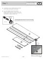 5
5
-
 6
6
-
 7
7
-
 8
8
-
 9
9
-
 10
10
-
 11
11
-
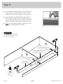 12
12
-
 13
13
-
 14
14
-
 15
15
-
 16
16
-
 17
17
-
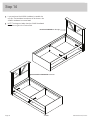 18
18
-
 19
19
-
 20
20
-
 21
21
-
 22
22
-
 23
23
-
 24
24
-
 25
25
-
 26
26
-
 27
27
-
 28
28


Sauder Mates Bed 423003 Instrucciones de operación
- Tipo
- Instrucciones de operación
en otros idiomas
Artículos relacionados
-
Sauder 419517 Instrucciones de operación
-
-
-
-
-
-
-
-
-