
O PER ATING I N S T R U C T I O N
en / de / fr / pt / it / es / zh / ja / ru
SICK AG, Erwin-Sick-Strasse 1, D-79183 Waldkirch
8016719.10DB
2006/42/EG
NO
SAFETY

Photoelectric retro-reflective sensor
Operating instructions
1 Safety notes
■
Read the operating instructions before commissioning.
■
Connection, mounting, and setting may only be performed by trained specialists.
■
Not a safety component in accordance with the EU Machinery Directive.
■
UL: Only for use in applications in accordance with NFPA 79. Adapters listed by UL
with connection cables are available. Enclosure type 1.
■
When commissioning, protect the device from moisture and contamination.
■
These operating instructions contain information required during the life cycle of
the sensor.
2 Correct use
The WL12G-3P3572S12 is an opto-electronic photoelectric retro-reflective sensor (re‐
ferred to as "sensor" in the following) for the optical, non-contact detection of objects,
animals, and persons. A reflector is required for this product to function. If the product
is used for any other purpose or modified in any way, any warranty claim against SICK
AG shall become void.
Photoelectric retro-reflective sensor
with additional option for the detection of transpa‐
rent objects.
3 Commissioning
1 Check the distance between sensor and reflector. There is a max. sensing range of
500 mm with reflector P250F.
2 Mount the sensor and the reflector using suitable mounting brackets (see the SICK
range of accessories). Align the sensor and reflector with each other.
Note the sensor's maximum permissible tightening torque of Nm.
8016719.10DB| SICK
Subject to change without notice
1

3 The sensors must be connected in a voltage-free state (V
S
= 0 V). The information
in the graphics [B] must be observed, depending on the type of connection:
–
Male connector connection: pin assignment
+ (L+)
Q
- (M)
brn
wht
blu
1
2
3
Q
blk
4
Teach
gra
5
Image: B
Only apply voltage / switch on the power supply (V
S
> 0 V) once all electrical con‐
nections have been completed. The green LED indicator lights up on the sensor.
Explanations of the connection diagram (graphic B):
Switching outputs Q and /Q (according to graphic B):
WL12G-3P3572S12 (PNP: load -> M)
ET = external teach-in (see Adjustment)
4 Align the sensor with a suitable reflector. Select the position so that the red emit‐
ted light beam hits the center of the reflector. The sensor must have a clear view of
the reflector, with no object in the path of the beam [see E]. You must ensure that
the optical openings of the sensor and reflector are completely clear. Place clear
off tape on clear foil at a distance of 60 mm between sensor and reflector.
3 COMMISSIONING
2
8016719.10DB| SICK
Subject to change without notice

5
Sensor with teach-in via pushbutton and / or cable:
The sensor must be taught to detect transparent objects.
The sensitivity can be adjusted in accordance with Table J by pressing the teach-in
button or by activating the teach function via cable. Do not operate the teach-in
button using sharp objects.
Image: G
Teach-in mo‐
de for ob‐
jects /
Teach-in mo‐
de for objects
Light dam‐
ping /
Light dam‐
ping
Object ty‐
pe /
Object type
Teach-in
time /
Teach-in
time
Ext. Cable
teach-in /
Ext. Cable
teach-in
LED indica‐
tor /
LED indica‐
tor
I 6% PET bottle/
Clear tear
off tape on
clear foil /
PET bottle/
Clear tear
off tape on
clear foil
1 to 5 s 30 to 100
ms
yellow /
yellow
II 10% Glass /
Glass
5 to 10 s 100 to 200
ms
Blue /
Blue
III 18% Colored
bottles /
Colored
bottles
> 10 s > 200 ms Light blue /
Light blue
4
3
8016719.10DB| SICK
Subject to change without notice

5 Fault diagnosis
Table indicates which measures are to be taken if the sensor stops working.
6 Table Fault diagnosis
LED indicator/fault pattern /
LED indicator/fault pattern
Cause /
Cause
Measures /
Measures
Green LED does not light up /
Green LED does not light up
No voltage or voltage below
the limit values /
No voltage or voltage below
the limit values
Check the power supply,
check all electrical connecti‐
ons (cables and plug connecti‐
ons) /
Check the power supply,
check all electrical connecti‐
ons (cables and plug connecti‐
ons)
Green LED does not light up /
Green LED does not light up
Voltage interruptions /
Voltage interruptions
Ensure there is a stable power
supply without interruptions /
Ensure there is a stable power
supply without interruptions
Green LED does not light up /
Green LED does not light up
Sensor is faulty /
Sensor is faulty
If the power supply is OK, re‐
place the sensor /
If the power supply is OK, re‐
place the sensor
Yellow LED flashes /
Yellow LED flashes
Sensor is still ready for opera‐
tion, but the operating conditi‐
ons are not ideal /
Sensor is still ready for opera‐
tion, but the operating conditi‐
ons are not ideal
Check the operating conditi‐
ons:
Fully align the beam of
light (light spot) with the re‐
flector. / Clean the optical sur‐
faces (sensor and reflector). /
Readjust the sensitivity / Re‐
flector is not suitable for the
application in question (we re‐
commend only using SICK re‐
flectors) / Check sensing ran‐
ge and adjust if necessary;
see graphic H. / Distance bet‐
ween the sensor and the re‐
flector is too long /
Check the operating conditi‐
ons: Fully align the beam of
light (light spot) with the re‐
flector. / Clean the optical sur‐
faces (sensor and reflector). /
Readjust the sensitivity / Re‐
flector is not suitable for the
application in question (we re‐
commend only using SICK re‐
flectors) / Check sensing ran‐
ge and adjust if necessary;
see graphic H. / Distance bet‐
ween the sensor and the re‐
flector is too long
5 FAULT DIAGNOSIS
4
8016719.10DB| SICK
Subject to change without notice

LED indicator/fault pattern /
LED indicator/fault pattern
Cause /
Cause
Measures /
Measures
Signal interruptions when ob‐
ject is detected /
Signal interruptions when ob‐
ject is detected
Depolarizing property of the
object surface (e.g., tape), re‐
flection /
Depolarizing property of the
object surface (e.g., tape), re‐
flection
Reduce sensitivity or change
the position of the sensor /
Reduce sensitivity or change
the position of the sensor
7 Disassembly and disposal
The sensor must be disposed of according to the applicable country-specific regulati‐
ons. Efforts should be made during the disposal process to recycle the constituent ma‐
terials (particularly precious metals).
8 Maintenance
SICK sensors are maintenance-free.
We recommend doing the following regularly:
•
Clean the external lens surfaces
•
Check the screw connections and plug-in connections
No modifications may be made to devices.
Subject to change without notice. Specified product properties and technical data are
not written guarantees.
DISASSEMBLY AND DISPOSAL 7
5
8016719.10DB| SICK
Subject to change without notice

Reflexions-Lichtschranke
Betriebsanleitung
9 Sicherheitshinweise
■
Vor der Inbetriebnahme die Betriebsanleitung lesen.
■
Anschluss, Montage und Einstellung nur durch Fachpersonal.
■
Kein Sicherheitsbauteil gemäß EU-Maschinenrichtlinie.
■
UL: Nur zur Verwendung in Anwendungen gemäß NFPA 79. Von UL gelistete Adap‐
ter mit Anschlusskabeln sind verfügbar. Enclosure type 1.
■
Gerät bei Inbetriebnahme vor Feuchte und Verunreinigung schützen.
■
Diese Betriebsanleitung enthält Informationen, die während des Lebenszyklus des
Sensors notwendig sind.
10 Bestimmungsgemäße Verwendung
Die WL12G-3P3572S12 ist eine optoelektronische Reflexions-Lichtschranke (im Fol‐
genden Sensor genannt) und wird zum optischen, berührungslosen Erfassen von Sa‐
chen, Tieren und Personen eingesetzt. Zur Funktion wird ein Reflektor benötigt. Bei je‐
der anderen Verwendung und bei Veränderungen am Produkt verfällt jeglicher Gewähr‐
leistungsanspruch gegenüber der SICK AG.
Reflexions-Lichtschranke mit Zusatzoption zur Erkennung transparenter Objekte
(WLxxG-xxxx).
11 Inbetriebnahme
1 Distanz zwischen Sensor und Reflektor prüfen. Der max. Schaltabstand beträgt
500 mm mit dem Reflektor P250F.
2 Sensor und Reflektor an geeignete Befestigungswinkel montieren (siehe SICK-Zu‐
behör-Programm). Sensor und Reflektor zueinander ausrichten.
Maximal zulässiges Anzugsdrehmoment des Sensors von Nm beachten.
6
8016719.10DB| SICK
Subject to change without notice

3 Anschluss der Sensoren muss spannungsfrei (V
S
= 0 V) erfolgen. Je nach An‐
schlussart sind die Informationen in den Grafiken [vgl. B] zu beachten:
–
Steckeranschluss: Pinbelegung
+ (L+)
Q
- (M)
brn
wht
blu
1
2
3
Q
blk
4
Teach
gra
5
Abb.: B
Erst nach Anschluss aller elektrischen Verbindungen die Spannungsversorgung (V
S
> 0 V) anlegen bzw. einschalten. Am Sensor leuchtet die grüne Anzeige-LED.
Erläuterungen zum Anschlussschema (Grafik B):
Schaltausgänge Q bzw. /Q (gemäß Grafik B):
WL12G-3P3572S12 (PNP: Last -> M)
ET = externer Teach (siehe Einstellung)
4 Sensor auf geeigneten Reflektor ausrichten. Positionierung so wählen, dass der ro‐
te Sendelichtstrahl in der Mitte des Reflektors auftrifft. Der Sensor muss freie Sicht
auf den Reflektor haben, es darf sich kein Objekt im Strahlengang befinden [vgl.
E]. Es ist darauf zu achten, dass die optischen Öffnungen von Sensor und Reflektor
vollständig frei sind. Transparente Folie mit Faden im Abstand 60 mm in den
Strahlengang bringen.
INBETRIEBNAHME 11
7
8016719.10DB| SICK
Subject to change without notice

5
Sensor mit Teach-in über Taste und / oder über Leitung:
Zur Erkennung transparenter Objekte ist ein Teachen des Sensors erforderlich.
Durch Drücken der Teach-in-Taste bzw. Aktivierung der Teach-Funktion über Lei‐
tung wird die Empfindlichkeit gemäß Tabelle J eingestellt. Teach-in-Taste nicht mit
spitzen Gegenständen betätigen.
Abb.: G
11 INBETRIEBNAHME
8
8016719.10DB| SICK
Subject to change without notice

Teach-in-Mo‐
dus für Ob‐
jekte /
Teach-in mo‐
de for objects
Lichtdämp‐
fung /
Light dam‐
ping
Objekttyp /
Object type
Teach-in-
Zeit /
Teach-in
time
Ext. Teach-
in über Lei‐
tung /
Ext. Cable
teach-in
Anzeige-
LED /
LED indica‐
tor
I 6 % PET-Fla‐
sche /
Transparen‐
ter Faden
mit Folie /
PET-Fla‐
sche /
Transparen‐
ter Faden
mit Folie
1 ... 5 s 30 ... 100
ms
gelb /
yellow
II 10 % Glas /
Glass
5 ... 10 s 100 ... 200
ms
blau /
Blue
III 18 % Farbige Fla‐
schen /
Colored
bottles
> 10 s > 200 ms hellblau /
Light blue
13 Fehlerdiagnose
Tabelle zeigt, welche Maßnahmen durchzuführen sind, wenn die Funktion des Sen‐
sors nicht mehr gegeben ist.
14 Tabelle Fehlerdiagnose
Anzeige-LED / Fehlerbild /
LED indicator/fault pattern
Ursache /
Cause
Maßnahme /
Measures
grüne LED leuchtet nicht /
Green LED does not light up
keine Spannung oder Span‐
nung unterhalb der Grenzwer‐
te /
No voltage or voltage below
the limit values
Spannungsversorgung prüfen,
den gesamten elektrischen
Anschluss prüfen (Leitungen
und Steckerverbindungen) /
Check the power supply,
check all electrical connecti‐
ons (cables and plug connecti‐
ons)
grüne LED leuchtet nicht /
Green LED does not light up
Spannungsunterbrechungen /
Voltage interruptions
Sicherstellen einer stabilen
Spannungsversorgung ohne
Unterbrechungen /
Ensure there is a stable power
supply without interruptions
grüne LED leuchtet nicht /
Green LED does not light up
Sensor ist defekt /
Sensor is faulty
Wenn Spannungsversorgung
in Ordnung ist, dann Sensor
austauschen /
If the power supply is OK, re‐
place the sensor
12
9
8016719.10DB| SICK
Subject to change without notice

Anzeige-LED / Fehlerbild /
LED indicator/fault pattern
Ursache /
Cause
Maßnahme /
Measures
gelbe LED blinkt /
Yellow LED flashes
Sensor ist noch betriebsbe‐
reit, aber die Betriebsbedin‐
gungen sind nicht optimal /
Sensor is still ready for opera‐
tion, but the operating conditi‐
ons are not ideal
Betriebsbedingungen prüfen:
Lichtstrahl (Lichtfleck) voll‐
ständig auf den Reflektor aus‐
richten / Reinigung der opti‐
schen Flächen(Sensor und
Reflektor)
/ Empfindlichkeit
neu einstellen / Reflektor eig‐
net sich nicht für gewählte Ap‐
plikation (wir empfehlen, aus‐
schließlich SICK-Reflektoren
zu verwenden) / Schaltab‐
stand überprüfen und ggf. an‐
passen, siehe Grafik H. / Ab‐
stand zwischen Sensor und
Reflektor ist zu groß /
Check the operating conditi‐
ons: Fully align the beam of
light (light spot) with the re‐
flector. / Clean the optical sur‐
faces (sensor and reflector). /
Readjust the sensitivity / Re‐
flector is not suitable for the
application in question (we re‐
commend only using SICK re‐
flectors) / Check sensing ran‐
ge and adjust if necessary;
see graphic H. / Distance bet‐
ween the sensor and the re‐
flector is too long
Signalunterbrechungen bei Ob‐
jektdetektion /
Signal interruptions when ob‐
ject is detected
Depolarisierende Eigenschaft
der Objektoberfläche (z. B. Fo‐
lie), Umspiegelung /
Depolarizing property of the
object surface (e.g., tape), re‐
flection
Empfindlichkeit reduzieren
oder Sensorposition verän‐
dern /
Reduce sensitivity or change
the position of the sensor
15 Demontage und Entsorgung
Die Entsorgung des Sensors hat gemäß den länderspezifisch anwendbaren Vorschrif‐
ten zu erfolgen. Für die enthaltenen Wertstoffe (insbesondere Edelmetalle) ist im Rah‐
men der Entsorgung eine Verwertung anzustreben.
16 Wartung
SICK-Sensoren sind wartungsfrei.
Wir empfehlen, in regelmäßigen Abständen
•
die optischen Grenzflächen zu reinigen
•
Verschraubungen und Steckverbindungen zu überprüfen
Veränderungen an Geräten dürfen nicht vorgenommen werden.
Irrtümer und Änderungen vorbehalten. Angegebene Produkteigenschaften und techni‐
sche Daten stellen keine Garantieerklärung dar.
15 DEMONTAGE UND ENTSORGUNG
10
8016719.10DB| SICK
Subject to change without notice

Barrière réflexe
Notice d'instruction
17 Consignes de sécurité
■
Lire la notice d'instruction avant la mise en service.
■
Confier le raccordement, le montage et le réglage uniquement à un personnel
spécialisé.
■
Il ne s'agit pas d'un composant de sécurité au sens de la directive machines CE.
■
UL : utilisation uniquement dans des applications selon la NFPA 79. Des adapta‐
teurs listés UL avec câbles de connexion sont disponibles. Enclosure type 1.
■
Protéger l'appareil contre l'humidité et les impuretés lors de la mise en service.
■
Cette notice d'instruction contient des informations nécessaires pendant toute la
durée de vie du capteur.
18 Utilisation conforme
WL12G-3P3572S12 est une barrière réflexe optoélectronique (appelée capteur dans
ce document) qui permet la détection optique sans contact d'objets, d'animaux et de
personnes. Un réflecteur est nécessaire à son fonctionnement. Toute autre utilisation
ou modification du produit annule la garantie de SICK AG.
Détecteur à réflexion directe avec option de détection d'objets transparents.
19 Mise en service
1 Contrôler la distance entre le capteur et le réflecteur. La portée max. avec le réflec‐
teur P250F est de 500 mm.
2 Monter le capteur et le réflecteur sur des équerres de fixation adaptées (voir la
gamme d'accessoires SICK). Aligner le capteur sur le réflecteur.
Respecter le couple de serrage maximum autorisé du capteur de Nm
12
8016719.10DB| SICK
Subject to change without notice

3 Le raccordement des capteurs doit s'effectuer hors tension (V
S
= 0 V). Selon le mo‐
de de raccordement, respecter les informations contenues dans les schémas [B] :
–
Raccordement du connecteur : affectation des broches
+ (L+)
Q
- (M)
brn
wht
blu
1
2
3
Q
blk
4
Teach
gra
5
Image: B
Après avoir terminé tous les raccordements électriques, enclencher l'alimentation
électrique (V
S
> 0 V). La DEL verte s'allume sur le capteur.
Explications relatives au schéma de raccordement (schéma B) :
Sorties de commutation Q ou /Q (selon le schéma B) :
WL12G-3P3572S12 (PNP : charge -> M)
ET = apprentissage externe (voir le réglage)
4 Aligner le capteur sur un réflecteur adéquat. Sélectionner la position de sorte que
le faisceau lumineux émis rouge touche le réflecteur en plein milieu. Le capteur
doit disposer d'un champ de vision dégagé sur le réflecteur, il ne doit donc y avoir
aucun objet dans la trajectoire du faisceau [voir E]. S'assurer que les ouvertures
optiques du capteur et du réflecteur sont parfaitement dégagées. Introduire un
film transparent avec un fil dans la trajectoire du faisceau, à une distance de 60
mm.
MISE EN SERVICE 19
13
8016719.10DB| SICK
Subject to change without notice

5
Capteur avec apprentissage via touche et/ou câble :
L'apprentissage du capteur est nécessaire pour la détection d'objets transparents.
Régler la portée selon le tableau J en appuyant sur la touche d'apprentissage ou
en activant la fonction apprentissage via l'entrée dédiée. Ne pas appuyer sur la
touche apprentissage avec des objets pointus.
Image: G
19 MISE EN SERVICE
14
8016719.10DB| SICK
Subject to change without notice

Mode d'ap‐
prentissage
pour les ob‐
jets /
Teach-in mo‐
de for objects
Atténuation
de la lumiè‐
re /
Light dam‐
ping
Type d'ob‐
jet /
Object type
Durée d'ap‐
prentissa‐
ge /
Teach-in
time
Apprentis‐
sage ext.
par câble /
Ext. Cable
teach-in
LED d'é‐
tat /
LED indica‐
tor
I 6 % Bouteille en
plastique /
fil transpa‐
rent avec
film /
Bouteille en
plastique /
fil transpa‐
rent avec
film
1 à 5 s 30 à 100
ms
jaune /
yellow
II 10 % Verre /
Glass
5 à 10 s 100 à 200
ms
bleu /
Blue
III 18 % Bouteilles
de cou‐
leur /
Colored
bottles
> 10 s > 200 ms bleu clair /
Light blue
21 Diagnostic
Le tableau présente les mesures à appliquer si le capteur ne fonctionne plus.
22 Tableau Diagnostic
LED d'état / image du défaut /
LED indicator/fault pattern
Cause /
Cause
/
Measures
La LED verte ne s'allume pas /
Green LED does not light up
Pas de tension ou tension in‐
férieure aux valeurs limites /
No voltage or voltage below
the limit values
Contrôler l'alimentation élect‐
rique, contrôler tous les bran‐
chements électriques (câbles
et connexions) /
Check the power supply,
check all electrical connecti‐
ons (cables and plug connecti‐
ons)
La LED verte ne s'allume pas /
Green LED does not light up
Coupures d'alimentation élect‐
rique /
Voltage interruptions
S'assurer que l'alimentation
électrique est stable et ini‐
nterrompue /
Ensure there is a stable power
supply without interruptions
La LED verte ne s'allume pas /
Green LED does not light up
Le capteur est défectueux /
Sensor is faulty
Si l'alimentation électrique est
en bon état, remplacer le cap‐
teur /
If the power supply is OK, re‐
place the sensor
20
15
8016719.10DB| SICK
Subject to change without notice

LED d'état / image du défaut /
LED indicator/fault pattern
Cause /
Cause
/
Measures
La LED jaune clignote /
Yellow LED flashes
Le capteur est encore opérati‐
onnel, mais les conditions d'u‐
tilisation ne sont pas idéales /
Sensor is still ready for opera‐
tion, but the operating conditi‐
ons are not ideal
Vérifier les conditions d'utilisa‐
tion : Diriger le faisceau lumi‐
neux (spot lumineux) entière‐
ment sur le réflecteur / Netto‐
yage des surfaces optiqu‐
es
(capteur et réflecteur) /
Régler à nouveau la sensibili‐
té / Le réflecteur ne convient
pas à l'application sélection‐
née (nous recommandons d'u‐
tiliser exclusivement des ré‐
flecteurs SICK) / Contrôler la
portée et éventuellement l'a‐
dapter, voir le schéma et H. /
La distance entre le capteur
et le réflecteur est trop gran‐
de /
Check the operating conditi‐
ons: Fully align the beam of
light (light spot) with the re‐
flector. / Clean the optical sur‐
faces (sensor and reflector). /
Readjust the sensitivity / Re‐
flector is not suitable for the
application in question (we re‐
commend only using SICK re‐
flectors) / Check sensing ran‐
ge and adjust if necessary;
see graphic H. / Distance bet‐
ween the sensor and the re‐
flector is too long
Coupures de signal lors de dé‐
tection d'objet /
Signal interruptions when ob‐
ject is detected
Propriété dépolarisante de la
surface de l'objet (par ex.
film), réflexions /
Depolarizing property of the
object surface (e.g., tape), re‐
flection
Réduire la sensibilité ou chan‐
ger la position du capteur /
Reduce sensitivity or change
the position of the sensor
23 Démontage et mise au rebut
La mise au rebut du capteur doit respecter la réglementation nationale en vigueur.
Dans le cadre de la mise au rebut, veiller à recycler les matériaux (notamment les mé‐
taux précieux).
24 Maintenance
Les capteurs SICK ne nécessitent aucune maintenance.
Nous vous recommandons de procéder régulièrement
•
au nettoyage des surfaces optiques
•
au contrôle des vissages et des connexions enfichables
Ne procéder à aucune modification sur les appareils.
Sujet à modification sans préavis. Les caractéristiques du produit et techniques four‐
nies ne sont pas une déclaration de garantie.
23 DÉMONTAGE ET MISE AU REBUT
16
8016719.10DB| SICK
Subject to change without notice

Barreira de luz de reflexão
Manual de instruções
25 Notas de segurança
■
Ler as instruções de operação antes da colocação em funcionamento.
■
A conexão, a montagem e o ajuste devem ser executados somente por pessoal
técnico qualificado.
■
Os componentes de segurança não se encontram em conformidade com a Direti‐
va Europeia de Máquinas.
■
UL: Somente na utilização em aplicações de acordo com NFPA 79. Estão disponív‐
eis adaptadores listados pela UL com cabos de conexão. Enclosure type 1.
■
Durante o funcionamento, manter o aparelho protegido contra impurezas e um‐
idade.
■
Este manual de instruções contém informações necessárias para toda a vida útil
do sensor.
26 Especificações de uso
O WL12G-3P3572S12 é uma barreira de luz de reflexão optoeletrônica (doravante de‐
nominada "sensor") utilizada para a detecção óptica, sem contato, de objetos, animais
e pessoas. É necessário um refletor para o funcionamento. Qualquer utilização diferen‐
te ou alterações do produto provocam a perda da garantia da SICK AG.
Barreira de luz de reflexão com opção adicional para a detecção de objetos transpa‐
rentes.
27 Colocação em funcionamento
1 Verificar a distância entre o sensor e o refletor. A distância de comutação máxima
é de 500 mm com o refletor P250F.
2 Montar o sensor e o refletor em cantoneiras de fixação adequadas (ver linha de
acessórios da SICK). Alinhar o sensor e o refletor entre si.
Observar o torque de aperto máximo permitido de Nm para o sensor.
18
8016719.10DB| SICK
Subject to change without notice

3 A conexão dos sensores deve ser realizada em estado desenergizado (V
S
= 0 V).
Conforme o tipo de conexão, devem ser observadas as informações contidas nos
gráficos [cp. B]:
–
Conector: Pin-out
+ (L+)
Q
- (M)
brn
wht
blu
1
2
3
Q
blk
4
Teach
gra
5
Image: B
Instalar ou ligar a alimentação de tensão (V
S
> 0 V) somente após a conclusão de
todas as conexões elétricas. O indicador LED verde está aceso no sensor.
Explicações relativas ao esquema de conexões (Gráfico B):
Saídas de comutação Q ou /Q (conforme o gráfico B):
WL12G-3P3572S12 (PNP: carga -> M)
TE = Teach externo (ver Ajuste)
4 Alinhar o sensor ao refletor adequado. Posicionar, de forma que o feixe da luz de
emissão vermelha incida sobre o centro do refletor. O espaço entre o sensor e o
refletor deve estar desimpedido; não pode haver objetos no caminho óptico [cp.
E]. Certificar-se de que as aberturas ópticas do sensor e do refletor estejam com‐
pletamente livres. Colocar a película transparente com fio no caminho óptico com
uma distância de 60 mm.
COLOCAÇÃO EM FUNCIONAMENTO 27
19
8016719.10DB| SICK
Subject to change without notice

5
Sensor com Teach-in através da tecla e / ou do cabo:
Para a detecção de objetos transparentes, é necessário um processo de teach do
sensor.
O ajuste da sensibilidade é efetuado de acordo com a tabela J apertando a tecla
Teach-in ou ativando a função Teach através do cabo. Não acionar a tecla Teach-in
com objetos pontiagudos.
Image: G
27 COLOCAÇÃO EM FUNCIONAMENTO
20
8016719.10DB| SICK
Subject to change without notice

Modo Teach-
in para obje‐
tos /
Teach-in mo‐
de for objects
Atenuação
de luz /
Light dam‐
ping
Tipo de ob‐
jeto /
Object type
Tempo de
Teach-in /
Teach-in
time
Ext. Teach-
in através
de cabo /
Ext. Cable
teach-in
Indicador
LED /
LED indica‐
tor
I 6 % Garrafa
PET / fio
transparen‐
te com pelí‐
cula /
Garrafa
PET / fio
transparen‐
te com pelí‐
cula
1 ... 5 s 30 ... 100
ms
Amarelo /
yellow
II 10% Vidro /
Glass
5 ... 10 s 100 ... 200
ms
azul /
Blue
III 18 % Garrafas
coloridas /
Colored
bottles
> 10 s > 200 ms azul claro /
Light blue
29 Diagnóstico de erros
A tabela mostra as medidas a serem executadas, quando o sensor não estiver funcio‐
nando.
30 Tabela Diagnóstico de erros
Indicador LED / padrão de er‐
ro /
LED indicator/fault pattern
Causa /
Cause
Medida /
Measures
LED verde apagado /
Green LED does not light up
Sem tensão ou tensão abaixo
dos valores-limite /
No voltage or voltage below
the limit values
Verificar a alimentação de
tensão, verificar toda a cone‐
xão elétrica (cabos e conecto‐
res) /
Check the power supply,
check all electrical connecti‐
ons (cables and plug connecti‐
ons)
LED verde apagado /
Green LED does not light up
Interrupções de tensão /
Voltage interruptions
Assegurar uma alimentação
de tensão estável sem inter‐
rupções /
Ensure there is a stable power
supply without interruptions
LED verde apagado /
Green LED does not light up
Sensor está com defeito /
Sensor is faulty
Se a alimentação de tensão
estiver em ordem, substituir o
sensor /
If the power supply is OK, re‐
place the sensor
28
21
8016719.10DB| SICK
Subject to change without notice

Indicador LED / padrão de er‐
ro /
LED indicator/fault pattern
Causa /
Cause
Medida /
Measures
LED amarelo intermitente /
Yellow LED flashes
Sensor ainda está operacio‐
nal, mas as condições de ope‐
ração não são ideais /
Sensor is still ready for opera‐
tion, but the operating conditi‐
ons are not ideal
Verificar as condições de ope‐
ração: Alinhar o feixe de luz
(ponto de luz) completamente
ao refletor
/ Limpeza das su‐
perfícies ópticas (sensor e re‐
fletor) / reajustar a sensibili‐
dade / Refletor não é adequa‐
do para a aplicação seleciona‐
da (recomendamos utilizar
apenas refletores SICK) / Veri‐
ficar e, se necessário, adaptar
a distância de comutação, ver
gráfico H. / Distância entre
sensor e refletor é grande de‐
mais /
Check the operating conditi‐
ons: Fully align the beam of
light (light spot) with the re‐
flector. / Clean the optical sur‐
faces (sensor and reflector). /
Readjust the sensitivity / Re‐
flector is not suitable for the
application in question (we re‐
commend only using SICK re‐
flectors) / Check sensing ran‐
ge and adjust if necessary;
see graphic H. / Distance bet‐
ween the sensor and the re‐
flector is too long
Interrupções de sinal na detec‐
ção de objetos /
Signal interruptions when ob‐
ject is detected
Propriedade despolarizante
da superfície do objeto (por
ex., película), reflexos de su‐
perfície /
Depolarizing property of the
object surface (e.g., tape), re‐
flection
Reduzir a sensibilidade ou
modificar a posição do sen‐
sor /
Reduce sensitivity or change
the position of the sensor
31 Desmontagem e descarte
O descarte do sensor deve ser efetuado de acordo com as normas aplicáveis específi‐
cas de cada país. No âmbito do descarte, deve-se procurar o aproveitamento dos ma‐
teriais recicláveis contidos (principalmente dos metais nobres).
32 Manutenção
Os sensores SICK não requerem manutenção.
Recomendamos que se efetue em intervalos regulares
•
uma limpeza das superfícies ópticas
•
uma verificação das conexões roscadas e dos conectores
Não são permitidas modificações no aparelho.
Sujeito a alterações sem aviso prévio. As propriedades do produto e os dados técnicos
especificados não constituem nenhum certificado de garantia.
31 DESMONTAGEM E DESCARTE
22
8016719.10DB| SICK
Subject to change without notice

Relè fotoelettrico a riflessione
Istruzioni per l'uso
33 Avvertenze sulla sicurezza
■
Prima della messa in funzionamento leggere le istruzioni per l'uso.
■
Allacciamento, montaggio e regolazione solo a cura di personale tecnico specializ‐
zato.
■
Nessun componente di sicurezza ai sensi della direttiva macchine UE.
■
UL: Solo per l'utilizzo in applicazioni ai sensi di NFPA 79. Sono disponibili adattato‐
ri elencati da UL con cavi di collegamento. Enclosure type 1.
■
Alla messa in funzionamento proteggere l'apparecchio dall'umidità e dalla sporci‐
zia.
■
Queste istruzioni per l'uso contengono le informazioni che sono necessarie du‐
rante il ciclo di vita del sensore fotoelettrico. deTec4 core
34 Uso conforme alle prescrizioni
La WL12G-3P3572S12 è un relè fotoelettrico a riflessione optoelettronica (di seguito
nominato sensore) utilizzato per il rilevamento ottico senza contatto di oggetti, animali
e persone. Per il funzionamento è necessario un riflettore. Se viene utilizzata diversa‐
mente e in caso di modifiche sul prodotto, decade qualsiasi diritto alla garanzia nei
confronti di SICK.
Relè fotoelettrico a riflessione optoelettronica con opzione supplementare per il rico‐
noscimento degli oggetti trasparenti.
35 Messa in funzione
1 Controllare la distanza tra sensore e riflettore. La max. distanza di commutazione è
500 mm con il riflettore P250F.
2 Montare il sensore e il riflettore su dei punti di fissaggio adatti (vedi il programma
per accessori SICK). Orientare reciprocamente il sensore e il rispettivo riflettore.
Rispettare il momento torcente massimo consentito del sensore di Nm.
24
8016719.10DB| SICK
Subject to change without notice

3 Il collegamento dei sensori deve avvenire in assenza di tensione (V
S
= 0 V). In base
al tipo di collegamento si devono rispettare le informazioni nei grafici [cfr. B]:
–
Collegamento a spina: assegnazione pin
+ (L+)
Q
- (M)
brn
wht
blu
1
2
3
Q
blk
4
Teach
gra
5
Image: B
Solamente in seguito alla conclusione di tutti i collegamenti elettrici, ripristinare o
accendere l'alimentazione di tensione (V
S
> 0 V). Sul sensore si accende l'indicato‐
re LED verde.
Spiegazioni dello schema di collegamento (grafico B):
Uscite di commutazione Q ovvero /Q (conformemente al grafico B):
WL12G-3P3572S12 (PNP: carico -> M)
ET = Teach esterno (vedi impostazione)
4 Orientare il sensore sul relativo riflettore. Scegliere la posizione in modo tale che il
raggio di luce rosso emesso colpisca il centro del riflettore. Il sensore deve avere
una visuale libera sul riflettore, non ci deve essere nessun oggetto nella traiettoria
del raggio [cfr. E]. Si deve fare attenzione affinché le aperture ottiche del sensore e
del riflettore siano completamente libere. Portare la pellicola trasparente con il fila‐
mento alla distanza di 60 mm nella traiettoria del raggio.
MESSA IN FUNZIONE 35
25
8016719.10DB| SICK
Subject to change without notice

5
Sensore con Teach-in tramite tasto e/o via cavo:
Per il riconoscimento degli oggetti trasparenti è necessaria una regolazione Teach
del sensore.
Premendo il tasto Teach-in o attivando la funzione via cavo, viene impostata la
sensibilità secondo la tabella J. Non azionare il tasto Teach-in con oggetti appunti‐
ti.
Image: G
35 MESSA IN FUNZIONE
26
8016719.10DB| SICK
Subject to change without notice

Modalità
Teach-in per
oggetti /
Teach-in mo‐
de for objects
Attenuazio‐
ne della lu‐
ce /
Light dam‐
ping
Tipo do og‐
getto /
Object type
Tempo
Teach-in /
Teach-in
time
Est. Teach-
in tramite
condutto‐
re /
Ext. Cable
teach-in
Indicatore -
LED /
LED indica‐
tor
I 6 % Bottiglia in
PET / fila‐
mento tra‐
sparente
con pellico‐
la /
Bottiglia in
PET / fila‐
mento tra‐
sparente
con pellico‐
la
1 ... 5 s 30 ... 100
ms
giallo /
yellow
II 10% Vetro /
Glass
5 ... 10 s 100 ... 200
ms
blu /
Blue
III 18 % Bottiglie co‐
lorate /
Colored
bottles
> 10 s > 200 ms azzurro /
Light blue
37 Diagnostica delle anomalie
La tabella mostra quali provvedimenti si devono adottare quando il sensore non funzi‐
ona più.
38 Tabella diagnostica delle anomalie
Indicatore LED / figura di erro‐
re /
LED indicator/fault pattern
Causa /
Cause
Provvedimento /
Measures
Il LED verde non si accende /
Green LED does not light up
nessuna tensione o tensione
al di sotto del valore soglia /
No voltage or voltage below
the limit values
Verificare la tensione di ali‐
mentazione e/o il collegamen‐
to elettrico /
Check the power supply,
check all electrical connecti‐
ons (cables and plug connecti‐
ons)
Il LED verde non si accende /
Green LED does not light up
Interruzioni di tensione /
Voltage interruptions
Assicurarsi che ci sia un'ali‐
mentazione di tensione stabi‐
le /
Ensure there is a stable power
supply without interruptions
Il LED verde non si accende /
Green LED does not light up
Il sensore è guasto /
Sensor is faulty
Se l'alimentazione di tensione
è regolare, allora chiedere
una sostituzione del sensore /
If the power supply is OK, re‐
place the sensor
36
27
8016719.10DB| SICK
Subject to change without notice

Indicatore LED / figura di erro‐
re /
LED indicator/fault pattern
Causa /
Cause
Provvedimento /
Measures
Il LED giallo lampeggia /
Yellow LED flashes
Il sensore è ancora pronto per
il funzionamento, ma le condi‐
zioni di esercizio non sono ot‐
timali /
Sensor is still ready for opera‐
tion, but the operating conditi‐
ons are not ideal
Controllare le condizioni di
esercizio: Dirigere il raggio di
luce (il punto luminoso) com‐
pletamente sul riflettore / Pu‐
lizia delle superfici ottiche
(sensore e riflettore) / Sensi‐
bilità
/ se il riflettore non è
adatto per l'applicazione sele‐
zionata (si consiglia, di usare
esclusivamente riflettori
SICK) / controllare la distanza
di commutazione e, se neces‐
sario, adattarla, vedi grafico
H. / La distanza tra sensore e
riflettore è troppo grande /
Check the operating conditi‐
ons: Fully align the beam of
light (light spot) with the re‐
flector. / Clean the optical sur‐
faces (sensor and reflector). /
Readjust the sensitivity / Re‐
flector is not suitable for the
application in question (we re‐
commend only using SICK re‐
flectors) / Check sensing ran‐
ge and adjust if necessary;
see graphic H. / Distance bet‐
ween the sensor and the re‐
flector is too long
Interruzioni di segnale al mo‐
mento del rilevamento dell'og‐
getto /
Signal interruptions when ob‐
ject is detected
Proprietà depolarizzante della
superficie dell'oggetto (ad es.
pellicola), riflesso /
Depolarizing property of the
object surface (e.g., tape), re‐
flection
Ridurre la sensibilità o variare
la posizione del sensore /
Reduce sensitivity or change
the position of the sensor
39 Smontaggio e smaltimento
Lo smaltimento del sensore deve avvenire conformemente alle direttive previste speci‐
ficatamente dal paese. Per i materiali riciclabili in esso contenuti (in particolare metalli
nobili) si auspica un riciclaggio nell'ambito dello smaltimento.
40 Manutenzione
I sensori SICK sono esenti da manutenzione.
A intervalli regolari si consiglia di
•
pulire le superfici limite ottiche
•
Verificare i collegamenti a vite e gli innesti a spina
Non è consentito effettuare modifiche agli apparecchi.
Contenuti soggetti a modifiche senza preavviso. Le proprietà del prodotto e le schede
tecniche indicate non costituiscono una dichiarazione di garanzia.
39 SMONTAGGIO E SMALTIMENTO
28
8016719.10DB| SICK
Subject to change without notice

Barrera fotoeléctrica de reflexión
Instrucciones de uso
41 Instrucciones de seguridad
■
Lea las instrucciones de uso antes de efectuar la puesta en servicio.
■
La conexión, el montaje y el ajuste deben ser efectuados exclusivamente por téc‐
nicos especialistas.
■
No se trata de un componente de seguridad según la Directiva de máquinas de la
UE.
■
UL: solo para utilizar en aplicaciones según NFPA 79. Se encuentran disponibles
adaptadores listados por UL con cable de conexión. Enclosure type 1.
■
Proteja el equipo contra la humedad y la suciedad durante la puesta en servicio.
■
Las presentes instrucciones de uso contienen información que puede serle nece‐
saria durante todo el ciclo de vida del sensor.
42 Uso conforme a lo previsto
La WL12G-3P3572S12 es una barrera optoelectrónica de reflexión (en lo sucesivo lla‐
mada sensor) empleada para la detección óptica y sin contacto de objetos, animales y
personas. Para que funcione es necesario un reflector. Cualquier uso diferente al pre‐
visto o modificación en el producto invalidará la garantía por parte de SICK AG.
Barrera fotoeléctrica de reflexión con opción adicional para detectar objetos transpa‐
rentes.
43 Puesta en servicio
1 Verificar la distancia entre el sensor y el reflector. La distancia máx. de conmutaci‐
ón es de 500 mm con el reflector P250F.
2 Montar el sensor y el reflector en escuadras de fijación adecuadas (ver programa
de accesorios SICK). Alinear el sensor y el reflector entre sí.
Respetar el par de apriete máximo admisible del sensor de Nm.
30
8016719.10DB| SICK
Subject to change without notice

3 Los sensores deben conectarse sin tensión (V
S
= 0 V). Debe tenerse en cuenta la
información de las figuras [B] en función de cada tipo de conexión:
–
Conexión de enchufes: asignación de pines
+ (L+)
Q
- (M)
brn
wht
blu
1
2
3
Q
blk
4
Teach
gra
5
Image: B
No conectar o aplicar la fuente de alimentación (V
S
> 0 V) hasta que no se hayan
realizado todas las conexiones eléctricas. En el sensor se ilumina el LED indicador
verde.
Explicaciones relativas al esquema de conexión (figura B)
Salidas conmutadas Q o /Q (según figura B):
WL12G-3P3572S12 (PNP: carga -> M)
ET = Aprendizaje externo (véase configuración)
4 Oriente el sensor hacia el reflector adecuado. Seleccione una posición que permita
que el haz de luz roja del transmisor incida en el centro del reflector. El sensor de‐
be tener una visión despejada del reflector, no puede haber ningún objeto en la
trayectoria del haz [véase Figura E]. Hay que procurar que las aperturas ópticas
del sensor y del reflector estén completamente libres. Colocar en la trayectoria del
haz una lámina transparente con hilo a una distancia de 60 mm.
PUESTA EN SERVICIO 43
31
8016719.10DB| SICK
Subject to change without notice

5
Sensor con aprendizaje mediante botón o cable:
Para detectar objetos transparentes, se requiere enseñar al sensor.
Pulsando el botón de aprendizaje o activando la función de aprendizaje por cable,
se ajusta la sensibilidad según tabla J. No accione el botón de aprendizaje con ob‐
jetos puntiagudos.
Image: G
43 PUESTA EN SERVICIO
32
8016719.10DB| SICK
Subject to change without notice

Modo de ap‐
rendizaje
(Teach-in) pa‐
ra objetos /
Teach-in mo‐
de for objects
Atenuación
de la luz /
Light dam‐
ping
Tipo de ob‐
jeto /
Object type
Tiempo de
aprendizaje
(Teach-in) /
Teach-in
time
Aprendizaje
(Teach-in)
ext. por
cable /
Ext. Cable
teach-in
LED indica‐
dor /
LED indica‐
tor
I 6 % Botella de
PET / hilo
transparen‐
te con lámi‐
na /
Botella de
PET / hilo
transparen‐
te con lámi‐
na
1 ... 5 s 30 ... 100
ms
amarillo /
yellow
II 10 % Vidrio /
Glass
5 ... 10 s 100 ... 200
ms
azul /
Blue
III 18 % Botellas de
color /
Colored
bottles
> 10 s > 200 ms azul claro /
Light blue
45 Diagnóstico de fallos
La tabla muestra las medidas que hay que tomar cuando ya no está indicado el funci‐
onamiento del sensor.
46 Tabla Diagnóstico de fallos
LED indicador / imagen de er‐
ror /
LED indicator/fault pattern
Causa /
Cause
Acción /
Measures
El LED verde no se ilumina /
Green LED does not light up
Sin tensión o tensión por de‐
bajo de los valores límite /
No voltage or voltage below
the limit values
Comprobar la fuente de ali‐
mentación, comprobar toda la
conexión eléctrica (cables y
conectores) /
Check the power supply,
check all electrical connecti‐
ons (cables and plug connecti‐
ons)
El LED verde no se ilumina /
Green LED does not light up
Interrupciones de tensión /
Voltage interruptions
Asegurar una fuente de ali‐
mentación estable sin inter‐
rupciones de tensión /
Ensure there is a stable power
supply without interruptions
El LED verde no se ilumina /
Green LED does not light up
El sensor está defectuoso /
Sensor is faulty
Si la fuente de alimentación
no tiene problemas, cambiar
el sensor /
If the power supply is OK, re‐
place the sensor
44
33
8016719.10DB| SICK
Subject to change without notice

LED indicador / imagen de er‐
ror /
LED indicator/fault pattern
Causa /
Cause
Acción /
Measures
El LED amarillo parpadea /
Yellow LED flashes
El sensor aún está operativo,
pero las condiciones de servi‐
cio no son óptimas /
Sensor is still ready for opera‐
tion, but the operating conditi‐
ons are not ideal
Comprobar las condiciones de
servicio: Alinear el haz de luz
(punto de luz) completamente
con el reflector / Limpieza de
las superficies ópticas
(sensor
y reflector) / Reajustar la sen‐
sibilidad / El reflector no es
adecuado para la aplicación
seleccionada (recomendamos
utilizar exclusivamente reflec‐
tores SICK) / Comprobar la
distancia de conmutación y, si
es necesario, adaptarla, véa‐
se Figura H. La distancia entre
el sensor y el reflector es ex‐
cesiva /
Check the operating conditi‐
ons: Fully align the beam of
light (light spot) with the re‐
flector. / Clean the optical sur‐
faces (sensor and reflector). /
Readjust the sensitivity / Re‐
flector is not suitable for the
application in question (we re‐
commend only using SICK re‐
flectors) / Check sensing ran‐
ge and adjust if necessary;
see graphic H. / Distance bet‐
ween the sensor and the re‐
flector is too long
Interrupciones de la señal al
detectar objetos /
Signal interruptions when ob‐
ject is detected
Propiedad despolarizante de
la superficie del objeto (p. ej.,
lámina plástica), reflexión /
Depolarizing property of the
object surface (e.g., tape), re‐
flection
Reducir la sensibilidad o mo‐
dificar la posición del sensor /
Reduce sensitivity or change
the position of the sensor
47 Desmontaje y eliminación
El sensor tiene que eliminarse siguiendo la normativa aplicable específica de cada pa‐
ís. Los materiales valiosos que contenga (especialmente metales nobles) deben ser eli‐
minados considerando la opción del reciclaje.
48 Mantenimiento
Los sensores SICK no precisan mantenimiento.
A intervalos regulares, recomendamos:
•
Limpiar las superficies ópticas externas
•
Comprobar las uniones roscadas y las conexiones.
No se permite realizar modificaciones en los aparatos.
Sujeto a cambio sin previo aviso. Las propiedades y los datos técnicos del producto no
suponen ninguna declaración de garantía.
47 DESMONTAJE Y ELIMINACIÓN
34
8016719.10DB| SICK
Subject to change without notice

镜反射式光电传感器
操作说明
49 安全须知
■
调试前请阅读操作说明。
■
仅允许由专业人员进行接线、安装和设置。
■
本设备非欧盟机械指令中定义的安全部件。
■
UL
:仅限用于符合 NFPA 79 的应用。可用 UL 所列出的含连接线缆的连接器.
Enclosure type 1.
■
调试前防止设备受潮或污染。
■
本操作说明中包含了传感器生命周期中必需的各项信息。
50 拟定用途
WL12G-3P3572S12 是一种光电反射式光栅(下文简称为“传感器”),用于物体、
动物和人体的非接触式光学检测。配备反射镜或者胶贴。如果滥用本产品或擅自更
改产品,则 SICK AG
公司所作之质保承诺均将失效。
配有可识别透明物体的选配件。
51 调试
1 检查传感器和反射器之间的间距。与反射器 P250F 之间的最大开关距离为 500
mm
。
2 将传感器和反射器安装在合适的安装托架上(参见 SICK 附件说明书)。相互对
准传感器和反射器。
注意传感器的最大允许拧紧扭矩为 Nm。
36
8016719.10DB| SICK
Subject to change without notice

3 必须在无电压状态 (V
S
= 0 V) 连接传感器。依据不同连接类型,注意图 [
参照
B] 中的信息:
– 插头连接:引线分配
+ (L+)
Q
- (M)
brn
wht
blu
1
2
3
Q
blk
4
Teach
gra
5
Image: B
完成所有电子连接后,才敷设或接通电源 (V
S
> 0 V)。传感器上的绿色 LED 指
示灯亮起。
接线图(图 B)说明:
开关输出端 Q 或 /Q(根据图 B):
WL12G-3P3572S12 (PNP:负载 -> M)
ET = 外部示教(参见设置)
4 将传感器对准合适的反射器。选择定位,确保红色发射光束射中反射器的中间。
传感器应无遮挡地观察到反射器,光路中不得有任何物体 [参照 E]。此时应注意
传感器和反射器的光学开口处应无任何遮挡。保持光路中透明薄膜与绞线之间的
距离为 60 mm。
调试 51
37
8016719.10DB| SICK
Subject to change without notice

5
带示教功能(按键和/或电缆)的传感器:
如需识别透明物体,则须传感器示教功能。
通过按下示教按键或通过电缆激活示教功能,可根据表 J 设置灵敏度。不得使
用尖锐物操作示教按键。
Image: G
51 调试
38
8016719.10DB| SICK
Subject to change without notice

物体示教模
式 /
Teach-in
mode for
objects
光衰减 /
Light dam‐
ping
物体型号 /
Object ty‐
pe
示教时间 /
Teach-in
time
外部通过导
线示教: /
Ext. Cable
teach-in
LED 指示
灯 /
LED indi‐
cator
I 6 % PET-瓶 /
透明绞线及
薄膜 /
PET-瓶 /
透明绞线及
薄膜
1 ... 5 s 30 ... 100
ms
黄色 /
yellow
II 10 % 玻璃 /
Glass
5 ... 10 s 100 ...
200 ms
蓝色 /
Blue
III 18 % 彩色瓶子 /
Colored
bottles
> 10 s > 200 ms 浅蓝色 /
Light blue
53 故障诊断
表 I 中罗列了传感器无法执行某项功能时应采取的各项措施。
54 表故障诊断
LED 指示灯 / 故障界面 /
LED indicator/fault pattern
原因 /
Cause
措施 /
Measures
绿色 LED 未亮起 /
Green LED does not light up
无电压或电压低于极限值 /
No voltage or voltage be‐
low the limit values
检查电源,检查整体电气连
接(导线和插头连接) /
Check the power supply,
check all electrical connec‐
tions (cables and plug con‐
nections)
绿色 LED 未亮起 /
Green LED does not light up
电压中断 /
Voltage interruptions
确保电源稳定无中断 /
Ensure there is a stable
power supply without inter‐
ruptions
绿色 LED 未亮起 /
Green LED does not light up
传感器损坏 /
Sensor is faulty
如果电源正常,则更换传感
器 /
If the power supply is OK,
replace the sensor
52
39
8016719.10DB| SICK
Subject to change without notice

LED 指示灯 / 故障界面 /
LED indicator/fault pattern
原因 /
Cause
措施 /
Measures
,黄色 LED 闪烁 /
Yellow LED flashes
尽管传感器准备就绪,但运
行条件不佳 /
Sensor is still ready for ope‐
ration, but the operating
conditions are not ideal
检查运行条件: 光束(光
斑)完全对准反射器 / 清洁
光学表面(传感器和反射
器) / 重新设置灵敏度 / 反
射器不适用于所选应用(我
们建议仅使用 SICK 反射
器) / 检查开关距离,必要
时调整;参见图 H.
/ 传感器
和反射器之间的间距过大 /
Check the operating condi‐
tions: Fully align the beam
of light (light spot) with the
reflector. / Clean the optical
surfaces (sensor and reflec‐
tor). / Readjust the sensitivi‐
ty / Reflector is not suitable
for the application in questi‐
on (we recommend only
using SICK reflectors) /
Check sensing range and
adjust if necessary; see
graphic H. / Distance bet‐
ween the sensor and the re‐
flector is too long
探测物体时信号中断 /
Signal interruptions when
object is detected
物体表面的去极化特性(例
如:薄膜),折射 /
Depolarizing property of the
object surface (e.g., tape),
reflection
降低灵敏度或更改传感器位
置 /
Reduce sensitivity or
change the position of the
sensor
55 拆卸和废弃处理
必须根据当地特定的法律法规废弃处理传感器。如果其中含有可回收材料(尤其是
贵金属),则必须在废弃处理时回收利用。
56 保养
SICK 传感器无需保养。
我们建议,定期:
•
清洁镜头检测面
•
检查螺栓连接和插头连接
不得对设备进行任何改装。
如有更改,不另行通知。所给出的产品特性和技术参数并非质保声明。
55 拆卸和废弃处理
40
8016719.10DB| SICK
Subject to change without notice

リフレクタ形光電センサ
取扱説明書
57 安全上の注意事項
■
ご使用前に必ず取扱説明書をお読みください。
■
本製品の接続・取り付け・設定は、訓練を受けた技術者が行って下さい。
■
本製品は EU
機械指令の要件を満たす安全コンポーネントではありません。
■
UL:NFPA79 に準拠した用途においてのみご使用ください。UL 規格によっ
てリストアップされた接続ケーブル付きのアダプターを使用できます。 Enc‐
losure type 1.
■
使用開始前に、湿気や汚れから機器を保護して下さい。
■
本取扱説明書には、センサのライフサイクル中に必要となる情報が記載され
ています。
58 正しいご使用方法
WL12G-3P3572S12 はリフレクタ形光電センサ(以下「センサ」)で、物体、動
物または人物などを光学的技術により非接触で検知するための装置です。この製
品が機能するためにはリフレクタが必要です。本製品が本来の使用用途以外の目
的に使用されたり、何らかの方法で改造された場合、SICK AG
に対するいかなる
保証要求も無効になります。
透明体検出の追加オプション付きリフレクタ形光電センサ。
59 使用開始
1 センサとリフレクタの間隔を点検します。リフレクタ P250F では、最大検出
距離は 500 mm
です。
2 適切なブラケットを使用してセンサとリフレクタを取り付けます(SICK 付属
品カタログを参照)。センサとリフレクタを互いに方向調整します。
センサの締め付けトルクの最大許容値 Nm に注意してください。
41
8016719.10DB| SICK
Subject to change without notice

3 センサの接続は必ず無電圧状態(V
S
= 0 V)で行ってください。接続タイプに
応じて、図 [B]
の情報に注意する必要があります:
– オスコネクタ接続:ピン割り当て
+ (L+)
Q
- (M)
brn
wht
blu
1
2
3
Q
blk
4
Teach
gra
5
Image: B
まずすべての電気接続を確立してから、電源(V
S
> 0 V)をオンにしてくださ
い。緑色の LED 表示灯がセンサ上で点灯します。
接続図の説明(図 B)。
スイッチング出力 Q および /Q(図 B に準拠):
WL12G-3P3572S12 (PNP:負荷 -> M)
ET = 外部ティーチイン(調整方法を参照)
4 センサを適切なリフレクタの方向に合わせます。赤色の投光軸がリフレクタの
中央に照射されるように位置を選択します。センサでの読み取りを可能にする
ため、リフレクタが遮らぎられたり、照射経路に対象物があったりしてはなり
ません [E を参照]。センサとリフレクタの光開口部が全く遮らぎられることが
ないよう、注意してください。60 mm の間隔で透明フィルムと繊維を光軸に
移動させます。
59 使用開始
42
8016719.10DB| SICK
Subject to change without notice

5
ボタンおよび/またはケーブルを介したティーチイン機能付きセンサ
透明な対象物を検出するには、センサのティーチングが必要です。
ティーチインボタンを押して、またはケーブルからティーチイン機能を有効に
し、感度を
J
表に従って設定します。ティーチインボタンを尖った物体で操作
しないでください。
Image: G
使用開始 59
43
8016719.10DB| SICK
Subject to change without notice

対象物のた
めのティー
チインモー
ド /
対象物のた
めのティー
チインモー
ド
光減衰 /
光減衰
対象物のタ
イプ /
対象物のタ
イプ
ティーチイ
ン時間 /
ティーチイ
ン時間
外部ケーブ
ルティーチ
イン /
外部ケーブ
ルティーチ
イン
LED 表示
灯 /
LED 表示
灯
I 6%
PET ボト
ル / 透明
繊維フィル
ム /
PET ボト
ル / 透明
繊維フィル
ム
1 ~ 5 秒 30 ~ 100
ミリ秒
黄色 /
yellow
II 10% ガラス /
ガラス
5 ~ 10 秒 100 ~
200
ミリ
秒
青色 /
青色
III 18%
色付きボト
ル /
色付きボト
ル
> 10 秒 > 200 ミ
リ秒
ライトブル
ー /
ライトブル
ー
61 故障診断
表 I は、センサが機能しなくなった場合に、どのような対策を講じるべきかを示
しています。
62 表エラー診断
LED 表示灯/故障パターン /
LED indicator/fault pattern
原因 /
Cause
対策 /
Acción
緑色の LED が点灯しない /
Green LED does not light up
無電圧、または電圧が限界
値以下 /
No voltage or voltage be‐
low the limit values
電源を確認し、すべての電
気接続(ケーブルおよびプ
ラグ接続)を確認します /
Check the power supply,
check all electrical connec‐
tions (cables and plug con‐
nections)
緑色の LED が点灯しない /
Green LED does not light up
電圧がきていない又は不安
定 /
Voltage interruptions
安定した電源電圧が供給さ
れていることを確認します /
Ensure there is a stable
power supply without inter‐
ruptions
緑色の LED が点灯しない /
Green LED does not light up
センサの異常 /
Sensor is faulty
電源に問題がなければ、セ
ンサを交換します /
If the power supply is OK,
replace the sensor
60
44
8016719.10DB| SICK
Subject to change without notice

LED 表示灯/故障パターン /
LED indicator/fault pattern
原因 /
Cause
対策 /
Acción
黄色い LED が点滅 /
Yellow LED flashes
センサの動作準備はまだ整
っているが、動作条件が最
適ではない /
Sensor is still ready for ope‐
ration, but the operating
conditions are not ideal
動作条件を確認します: 投
光光軸 (投光スポット) をリ
フレクタに完全に合わせま
す。 / 光学面の洗浄(
センサ
およびリフレクタ) / 感度を
再調整する / このリフレク
タは本アプリケーションに
適していません(SICK 製リ
フレクタのみ使用すること
をお勧めします) / 検出距
離を点検し必要に応じて調
整する、グラフ H 参照。 /
センサとリフレクタの間隔
が長すぎる /
Check the operating condi‐
tions: Fully align the beam
of light (light spot) with the
reflector. / Clean the optical
surfaces (sensor and reflec‐
tor). / Readjust the sensitivi‐
ty / Reflector is not suitable
for the application in questi‐
on (we recommend only
using SICK reflectors) /
Check sensing range and
adjust if necessary; see
graphic H. / Distance bet‐
ween the sensor and the re‐
flector is too long
対象物検出時の出力信号が不
安定 /
Signal interruptions when
object is detected
反射に偏りのある対象物表
面(例:テープ等)からの
反射光を無くします /
Depolarizing property of the
object surface (e.g., tape),
reflection
感度を下げるか、またはセ
ンサの位置を変えて下さい /
Reduce sensitivity or
change the position of the
sensor
63 解体および廃棄
センサは必ず該当国の規制にしたがって処分してください。廃棄処理の際には、
できるだけ構成材料をリサイクルするよう努めてください(特に貴金属類)。
64 メンテナンス
SICK センサはメンテナンスフリーです。
定期的に以下を行うことをお勧めしています:
•
レンズ境界面の清掃
•
ネジ締結と差込み締結の点検
機器を改造することは禁止されています。
記載内容につきましては予告なしに変更する場合がございますのであらかじめご
了承ください。指定された製品特性および技術データは保証書ではありません。
解体および廃棄 63
45
8016719.10DB| SICK
Subject to change without notice

Отражательный фоторелейный барьер
Руководство по эксплуатации
65 Указания по безопасности
■
Перед вводом в эксплуатацию изучите руководство по эксплуатации.
■
Подключение, монтаж и установку поручать только специалистам.
■
Не является оборудованием для обеспечения безопасности в соответствии с
Директивой ЕС по работе с машинным оборудованием.
■
UL: Только для использования в областях применения согласно
NFPA 79.
Доступны адаптеры с соединительными кабелями, перечисленные UL. Enclosu‐
re type 1.
■
При вводе в эксплуатацию защищать устройство от попадания грязи и влаги.
■
Данное руководство по эксплуатации содержит информацию, которая
необходима во время всего жизненного цикла сенсора.
66 Использование по назначению
WL12G-3P3572S12 является оптоэлектронным отражательным световым барьером
(в дальнейшем называемым "сенсор") и используется для оптической бесконтактной
регистрации вещей, животных и людей. Для функционирования необходим
отражатель. При ином использовании и при внесении изменений в изделие подача
любых гарантийных претензий к
SICK AG исключена.
Отражательный световой барьер с дополнительной опцией распознавания
прозрачных объектов.
67 Ввод в эксплуатацию
1 Скорректировать дистанцию между сенсором и отражателем с помощью
соответствующей диаграммы (
x = дистанция переключения, y =
функциональный резерв).
46
8016719.10DB| SICK
Subject to change without notice

2 Установите сенсор и отражатель на подходящем крепежном уголке (см.
программу принадлежностей от SICK).
Выровняйте сенсор и отражатель друг
относительно друга.
Выдерживайте максимально допустимый момент затяжки сенсора в Нм.
3 Подключайте сенсоры при отключенном напряжении питания (U
V
= 0 В). В
зависимости от типа подключения следует принять во внимание информацию с
графиков [см. B]:
–
Штекерный разъем: назначение контактов
+ (L+)
Q
- (M)
brn
wht
blu
1
2
3
Q
blk
4
Teach
gra
5
Image: B
Подавайте и включайте напряжение питания только после завершения
подключения всех электрических соединений (U
V
> 0 В). На сенсоре включается
зеленый светодиодный индикатор.
Пояснения к схеме электрических соединений (график B):
Коммутирующие выходы Q или /Q (согласно графику B):
WL12G-3P3572S12P (PNP: нагрузка -> M)
Teach = внешняя калибровка (ET) (см. настройку)
4 Направьте сенсор на подходящий отражатель. Выберите такую позицию, чтобы
красный луч передатчика попадал в центр отражателя. Сенсор должен иметь
свободную траекторию до отражателя, нахождение объектов на пути луча не
допускается [см. Е]. Оптические отверстия на сенсоре и отражателе должны быть
свободными.
Image: E
ВВОД В ЭКСПЛУАТАЦИЮ 67
47
8016719.10DB| SICK
Subject to change without notice

5
Сенсор в режиме калибровки с помощью переключателя и/или по кабелю:
Для распознавания прозрачных объектов требуется калибровка сенсора.
Путем нажатия кнопки калибровки или же активирования функции калибровки
по кабелю устанавливается чувствительность согласно таблице
J..
Не нажимайте
кнопку Teach-in острыми предметами.
Image: G
67 ВВОД В ЭКСПЛУАТАЦИЮ
48
8016719.10DB| SICK
Subject to change without notice

Режим
калибровки
для
объектов /
Teach-in mo‐
de for objects
Калибровк
а
времени /
Teach-in
time
Внешн.
калибровк
а по
кабелю /
Ext. Cable
teach-in
Выравнив
ание /
Alignment
Светодиод
ный
индикатор
/
LED indica‐
tor
Настройка
/
Adjustment
Автоматич
еская
адаптация
уровня
срабатыва
ния /
Continuous
threshold
adaptation
1
(прозрачный
) /
1 (transpa‐
rent)
> 1 ... 5 s ...
< 5 ... 10 s
с
ET:
подключите
Pin 2 или
белую жилу
кабеля для
> 1 ... 5 s …
< 5 ... 10 s
с к UV
(PNP). /
ET: Connect
pin 2 or
white wire
to UV for >
1 ... 5 s to <
5 ... 10 s s
(PNP).
Сенсор на
отражателе
/
Sensor to
reflector
Сенсор
распознает
объекты,
которые
демпфирую
т свет не
менее, чем
на 6% % /
The sensor
detects ob‐
jects that
dampen
the light by
at least 6%
%
да /
Yes
2
(прозрачный
или
непрозрачны
й) /
2 (transpa‐
rent or non-
transparent)
> > 10 s
с ET:
подключите
Pin 2 или
белую жилу
кабеля для
> > 10 s
с к
M (
PNP). /
ET: Connect
pin 2 or
white wire
to M for > >
10 s s
(PNP).
Сенсор на
отражателе
/
Sensor to
reflector
50% порог
срабатыва
ния /
50% of the
switching
threshold
нет /
No
3
(непрозрачн
ый) /
3 (non-trans‐
parent)
> > 10 s с ET:
подключите
Pin 2 или
белую жилу
кабеля для
> > 10 s
с к
M (
PNP). /
ET: Connect
pin 2 or
white wire
to M for > >
10 s s
(PNP).
Сенсор
направлен
в сторону,
не на
рефлектор
/
Sensor to
outside, not
to reflector
максималь
ная
чувствитель
ность /
Maximum
sensitivity
нет /
No
69 Диагностика неисправностей
В таблице показано, какие меры нужно предпринять, если сенсоры не работают.
68
49
8016719.10DB| SICK
Subject to change without notice

70 таблице диагностики неисправностей
Cветодиодный индикатор /
картина неисправности /
LED indicator/fault pattern
Причина /
Cause
Меры по устранению /
Measures
зеленый светодиод не горит /
Green LED does not light up
нет напряжения питания или
оно ниже нижнего
предельного значения /
No voltage or voltage below
the limit values
Проверить напряжения
питания, всю схему
электроподключения
(проводку и разъемные
соединения) /
Check the power supply,
check all electrical connecti‐
ons (cables and plug connecti‐
ons)
зеленый светодиод не горит /
Green LED does not light up
Пропадание напряжения
питания /
Voltage interruptions
Обеспечить надежную подачу
напряжения питания без его
пропадания /
Ensure there is a stable power
supply without interruptions
зеленый светодиод не горит /
Green LED does not light up
Сенсор неисправен /
Sensor is faulty
Если напряжение питания в
порядке, то заменить
сенсор /
If the power supply is OK, re‐
place the sensor
желтый светодиод мигает /
Yellow LED flashes
Сенсор пока еще готов к
работе, но эксплуатационные
условия не оптимальны /
Sensor is still ready for opera‐
tion, but the operating conditi‐
ons are not ideal
Проверка эксплуатационных
условий: Полностью
сориентировать световой луч
(световое пятно) на
отражатель
/ чистка
оптических поверхностей
(сенсор и отражатель)
/
заново настроить
чувствительность /
отражатель не подходит для
выбранного применения
(рекомендуется использовать
исключительно отражатели
SICK) / проверить и, при
необходимости,
скорректировать расстояние
срабатывания, см. график
H. / слишком велико
расстояние между сенсором
и отражателем /
Check the operating conditi‐
ons: Fully align the beam of
light (light spot) with the re‐
flector. / Clean the optical sur‐
faces (sensor and reflector). /
Readjust the sensitivity / Re‐
flector is not suitable for the
application in question (we re‐
commend only using SICK re‐
flectors) / Check sensing ran‐
ge and adjust if necessary;
see graphic H. / Distance bet‐
ween the sensor and the re‐
flector is too long
70 ТАБЛИЦЕ ДИАГНОСТИКИ НЕИСПРАВНОСТЕЙ
50
8016719.10DB| SICK
Subject to change without notice

Cветодиодный индикатор /
картина неисправности /
LED indicator/fault pattern
Причина /
Cause
Меры по устранению /
Measures
Пропадание сигнала при
детектировании объекта /
Signal interruptions when ob‐
ject is detected
Деполяризующие свойства
поверхности объекта
(например, пленка),
переотражение /
Depolarizing property of the
object surface (e.g., tape), re‐
flection
Уменьшить чувствительность
или изменить позицию
сенсора /
Reduce sensitivity or change
the position of the sensor
71 Демонтаж и утилизация
Утилизацию сенсоров следует проводить согласно национальным предписаниям по
утилизации. Следует стремиться к повторному использованию содержащихся в них
материалов (прежде всего, драгоценных металлов).
72 Техобслуживание
Датчики SICK не нуждаются в техобслуживании.
Рекомендуется регулярно
•
очищать оптические ограничивающие поверхности
•
проверять прочность резьбовых и штекерных соединений
Запрещается вносить изменения в устройства.
Право на ошибки и внесение изменений сохранено. Указанные свойства изделия и
технические характеристики не являются гарантией.
Sensing ran‐
ge (with re‐
flector
P250F)
Schaltab‐
stand (mit
Reflektor
P250F)
Portée
(avec réflec‐
teur P250F)
Distância
de comuta‐
ção (com re‐
fletor
P250F)
Distanza di
commuta‐
zione (con
riflettore
P250F)
Distancia
de conmu‐
tación (con
reflector
P250F)
开关距离
(带反射器
P250F)
最大検出範
囲
Sensing ran‐
ge max. (with
reflector
P250F)
Schaltab‐
stand max.
(mit Reflek‐
tor P250F)
Portée max.
(avec réflec‐
teur P250F)
Distância
de comuta‐
ção máx.
(com refle‐
tor P250F)
Distanza
max. di
commuta‐
zione (con
riflettore
P250F)
Distancia
de conmu‐
tación máx.
(con reflec‐
tor P250F)
最大开关距
离(带反射
器 P250F)
最大検出範
囲(リフレ
クタを用い
た場合
P250F)
0 ... 500
mm
Light spot di‐
ameter/
distance
Lichtfleck‐
durchmes‐
ser/Entfer‐
nung
Diamètre
spot / dis‐
tance
Diâmetro do
ponto de
luz/distân‐
cia
Diametro
punto lumi‐
noso/
distanza
Diámetro
del punto
luminoso/
distancia
光斑直径/
距离
光点のスポ
ット径/距
離
1.5 mm x 9
mm / 60
mm
Supply volta‐
ge V
S
Versor‐
gungsspan‐
nung U
V
Tension d'a‐
limentation
U
V
Tensão de
alimentação
U
V
Tensione di
alimentazio‐
ne U
V
Tensión de
alimentaci‐
ón U
V
供电电压
U
V
供給電圧 U
v
DC 10 ... 30
V
1)
Output cur‐
rent I
max.
Ausgangs‐
strom I
max.
Courant de
sortie I
max.
Corrente de
saída I
max.
Corrente di
uscita I
max.
Intensidad
de salida
I
max.
输出电流
I
max.
出力電流
I
max.
100 mA
Max. swit‐
ching fre‐
quency
Schaltfolge
max.
Commutati‐
on max.
Sequência
máx. de co‐
mutação
Sequenza di
commuta‐
zione max.
Secuencia
de conmu‐
tación máx.
最大开关操
作顺序
最大スイッ
チング周波
数
< 1,500
Hz
2)
ДЕМОНТАЖ И УТИЛИЗАЦИЯ 71
51
8016719.10DB| SICK
Subject to change without notice

Max. respon‐
se time
Ansprech‐
zeit max.
Temps de
réponse
max.
Tempo máx.
de resposta
Tempo di
reazione
max.
Tiempo de
respuesta
máx.
最长响应时
间
最大応答時
間
< 0,333
ms
3)
Enclosure ra‐
ting
Schutzart Indice de
protection
Tipo de pro‐
teção
Tipo di pro‐
tezione
Tipo de pro‐
tección
防护类型 保護等級 IP66,IP67
Protection
class
Schutzklas‐
se
Classe de
protection
Classe de
proteção
Classe di
protezione
Clase de
protección
防护等级 保護クラス II
Circuit pro‐
tection
Schutz‐
schaltungen
Protections
électriques
Circuitos de
proteção
Commutazi‐
oni di prote‐
zione
Circuitos de
protección
保护电路 回路保護 A,C,D
4)
Ambient ope‐
rating tempe‐
rature
Betriebsum‐
gebungstem‐
peratur
Températu‐
re de ser‐
vice
Temperatu‐
ra ambiente
de funciona‐
mento
Temperatu‐
ra ambien‐
tale di funzi‐
onamento
Temperatu‐
ra ambiente
de servicio
工作环境温
度
周辺温度
(作動中)
-40 ... +60
°C
1)
Limit value:
operation in
short-circuit
protection
mains max. 8
A; residual
ripple max. 5
Vss
2)
With light /
dark ratio 1:1
3)
Signal tran‐
sit time with
resistive load
4)
A = UV-con‐
nections re‐
verse polarity
protected
C = Interfe‐
rence sup‐
pression
D = outputs
overcurrent
and short-cir‐
cuit protec‐
ted
1)
Grenzwer‐
te: Betrieb
im kurz‐
schlussge‐
schützten
Netz max. 8
A; Restwel‐
ligkeit max.
5 Vss
2)
Mit Hell- /
Dunkelver‐
hältnis 1:1
3)
Signal‐
laufzeit bei
ohmscher
Last
4)
A = UV-An‐
schlüsse
verpolsicher
C = Störim‐
pulsunter‐
drückung
D = Ausgän‐
ge über‐
strom- und
kurzschluss‐
fest
1)
Valeurs li‐
mites : fonc‐
tionnement
sur réseau
protégé
contre les
courts-cir‐
cuits max. 8
A ; ondulati‐
on résiduel‐
le max. 5
Vcc
2)
Pour un
rapport
clair/somb‐
re de 1:1
3)
Temps de
propagation
du signal
sur charge
ohmique
4)
A = rac‐
cordements
UV protégés
contre les
inversions
de polarité
C = Sup‐
pression
des impulsi‐
ons parasi‐
tes
D = sorties
protégées
contre les
courts-cir‐
cuits et les
surcharges
1)
Valores li‐
mite: funcio‐
namento
com rede à
prova de
curto-circui‐
to máx. 8 A;
ondulação
residual
máx. 5 Vss
2)
Com pro‐
porção
sombra/luz
1:1
3)
Tempo de
funciona‐
mento do si‐
nal com car‐
ga ôhmica
4)
A = cone‐
xões prote‐
gidas contra
inversão de
pólos UV
C = Supre‐
ssão de im‐
pulsos para‐
sitas
D = Saídas
protegidas
contra so‐
brecorrente
e curto-cir‐
cuito
1)
Valori limi‐
te: funziona‐
mento in re‐
te protetta
da cortocir‐
cuito max. 8
A; ondula‐
zione resi‐
dua max. 5
Vss
2)
Con rap‐
porto chia‐
ro / scuro
1:1
3)
Durata
segnale con
carico ohmi‐
co
4)
A = UV-Al‐
lacciamenti
protetti dall‐
'inversione
di polarità
C = Sop‐
pressione
impulsi di
disturbo
D = uscite
protette da
sovracor‐
rente e da
cortocircui‐
to.
1)
Valores lí‐
mite: funcio‐
namiento
en red pro‐
tegida cont‐
ra cortocir‐
cuitos máx.
8 A; ondula‐
ción residu‐
al máx. 5
Vss
2)
Con una
relación cla‐
ro/oscuro
de 1:1
3)
Duración
de la señal
con carga
óhmica
4)
Conexio‐
nes A = UV
protegidas
contra pola‐
rización in‐
versa
C = Supresi‐
ón de impul‐
sos parási‐
tos
D=Salidas a
prueba de
sobrecorri‐
ente y corto‐
circuitos.
1)
极限值:
在防短路电
网中运行,
最大 8 A;
最大余波 5
Vss
2)
明暗比为
1:1
3)
信号传输
时间(电阻
负载时)
4)
A = UV 接
口(已采取
反极性保护
措施)
C = 抑制干
扰脉冲
D = 抗过载
电流和抗短
路输出端
1)
限界値:
短絡保護の
操作は最大
8 A;残留
リップルは
最大 5 Vss
2)
ライト/
ダークの比
率 1:1
3)
A = UV 接
続は逆接保
護
C = 干渉抑
制
D = 出力過
電流および
短絡保護
73
52
8016719.10DB| SICK
Subject to change without notice
-
 1
1
-
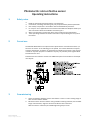 2
2
-
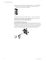 3
3
-
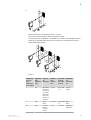 4
4
-
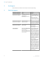 5
5
-
 6
6
-
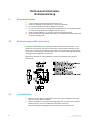 7
7
-
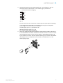 8
8
-
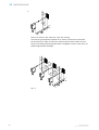 9
9
-
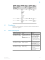 10
10
-
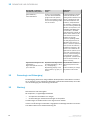 11
11
-
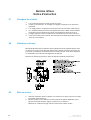 12
12
-
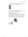 13
13
-
 14
14
-
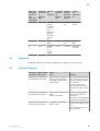 15
15
-
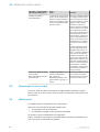 16
16
-
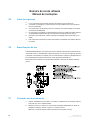 17
17
-
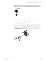 18
18
-
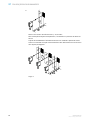 19
19
-
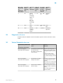 20
20
-
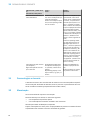 21
21
-
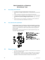 22
22
-
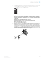 23
23
-
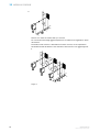 24
24
-
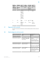 25
25
-
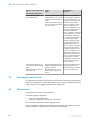 26
26
-
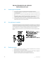 27
27
-
 28
28
-
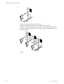 29
29
-
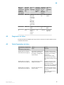 30
30
-
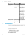 31
31
-
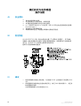 32
32
-
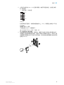 33
33
-
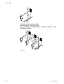 34
34
-
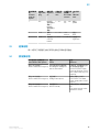 35
35
-
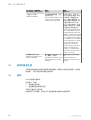 36
36
-
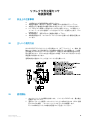 37
37
-
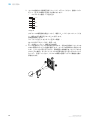 38
38
-
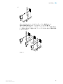 39
39
-
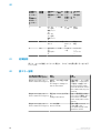 40
40
-
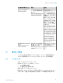 41
41
-
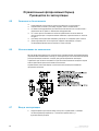 42
42
-
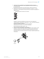 43
43
-
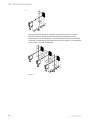 44
44
-
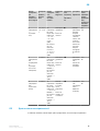 45
45
-
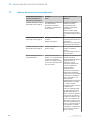 46
46
-
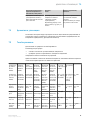 47
47
-
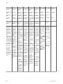 48
48


SICK WL12G-3P3572S12 Small photoelectric sensor Instrucciones de operación
- Tipo
- Instrucciones de operación
- Este manual también es adecuado para
en otros idiomas
- français: SICK WL12G-3P3572S12 Small photoelectric sensor Mode d'emploi
- italiano: SICK WL12G-3P3572S12 Small photoelectric sensor Istruzioni per l'uso
- English: SICK WL12G-3P3572S12 Small photoelectric sensor Operating instructions
- português: SICK WL12G-3P3572S12 Small photoelectric sensor Instruções de operação
- 日本語: SICK WL12G-3P3572S12 Small photoelectric sensor 取扱説明書
Artículos relacionados
-
SICK WL23-2 Compact photoelectric sensor Instrucciones de operación
-
-
-
-
-
-
-
-
-