SICK WL100-2 for transparent objects Instrucciones de operación
- Tipo
- Instrucciones de operación

O P E R A T I N G I N S T R U C T I O N
WL100-2 for transparent objects
Miniature photoelectric sensor
en / de / fr / pt / it / es / zh / ja / ru
8017526.YFI8

Photoelectric retro-reflective sensor
Operating instructions
2 Safety notes
■
Read the operating instructions before commissioning.
■
Connection, mounting, and setting may only be performed by trained specialists.
■
Not a safety component in accordance with the EU Machinery Directive.
■
When commissioning, protect the device from moisture and contamination.
■
These operating instructions contain information required during the life cycle of the sensor.
3 Correct use
Photoelectric retro-reflective sensor with additional option for the detection of transparent
objects
The WL100-2 is an opto-electronic photoelectric retro-reflective sensor (referred to as "sensor" in
the following) for the optical, non-contact detection of objects, animals, and persons. A reflector
is required for this product to function. If the product is used for any other purpose or modified in
any way, any warranty claim against SICK AG shall become void.
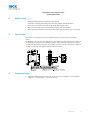
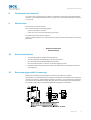
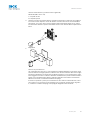
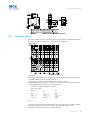
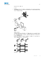
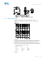
4 Commissioning
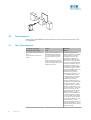
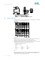
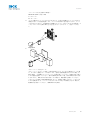
1 Adjust the distance between the sensor and the reflector according to the corresponding
diagram (x = sensing range, y = operating reserve).
8017526 | SICK
1

Image 1: H
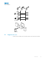
2 Mount the sensor and the reflector using suitable mounting brackets (see the SICK range of
accessories). Align the sensor and reflector with each other.
Note the sensor's maximum permissible tightening torque of < 0.5 Nm.
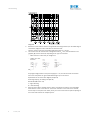
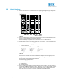
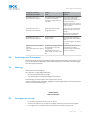
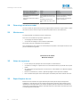
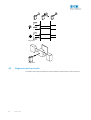
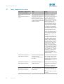
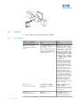
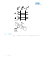
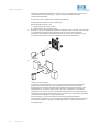
3 The sensors must be connected in a voltage-free state (V
S
= 0 V). The information in the
graphics [B] must be observed, depending on the type of connection:
– Male connector connection: pin assignment
– Cable: core color
Image 2: B
Only apply voltage/switch on the power supply (V
S
> 0 V) once all electrical connections
have been completed. The green LED indicator lights up on the sensor.
Explanations of the connection diagram (Graphic B):
Switching output Q (according to Graphic B):
WL100-2P (PNP: load -> M)
L = light switching
D = dark-switching
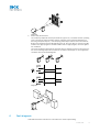
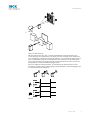
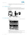
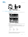
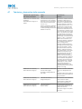
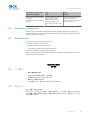
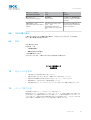
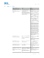
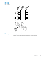
4 Align the sensor with a suitable reflector. Select the position so that the red emitted light
beam hits the center of the reflector. The sensor must have a clear view of the reflector,
with no object in the path of the beam [see E]. You must ensure that the optical openings of
the sensor and reflector are completely clear.
Commissioning
2
8017526 | SICK

Image 3: E
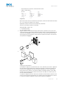
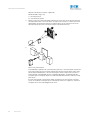
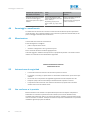
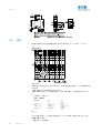
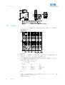
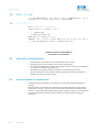
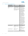
5 Sensor with potentiometer:
The sensitivity is adjusted with the potentiometer (type:
270°). Clockwise rotation: operating
reserve increased; counterclockwise rotation: operating reserve reduced. Adjustment for
detecting transparent objects (> 20% damping): Place object between sensor and reflector.
Reduce the sensitivity until the LED indicator goes out. Once the object is removed, the LED
indicator must light up again. If the LED indicator does not light up again, check the applica‐
tion conditions.
The sensor is adjusted and ready for operation. Refer to Graphics C and G to check the func‐
tion. If the switching output fails to behave in accordance with Graphic C, check application
conditions. See section Fault diagnosis.
Image 4: C
Image 5: G
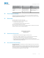
6 Fault diagnosis
Table indicates which measures are to be taken if the sensor stops working.
3
8017526 | SICK

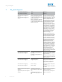
7 Tab_Fault diagnosis
LED indicator/fault pattern /
LED indicator/fault pattern
Cause /
Cause
Measures /
Measures
Green LED does not light up or
flickers /
Green LED does not light up or
flickers
Sensor is still ready for operation,
but the operating conditions are
not ideal (operating reserve factor
between 0.9 and 1.1) /
Sensor is still ready for operation,
but the operating conditions are
not ideal (operating reserve factor
between 0.9 and 1.1)
Check the operating conditions:
Fully align the beam of light (light
spot) with the reflector
/ Clean the
optical surfaces (sensor and
reflector) / Readjust the sensiti‐
vity (potentiometer) / If the poten‐
tiometer is set to the max. sen‐
sing range: Reduce the distance
between the sensor and the
reflector, and check the reflector
type against Graphic E / Reflector
is not suitable for the application
in question (we recommend only
using SICK reflectors) / Damping
of the object is < 20% / Check
sensing range and adjust if neces‐
sary, see Graphic E / Distance
between the sensor and the
reflector is too long /
Check the operating conditions:
Fully align the beam of light (light
spot) with the reflector / Clean
the optical surfaces (sensor and
reflector) / Readjust the sensiti‐
vity (potentiometer) / If the poten‐
tiometer is set to the max. sen‐
sing range: Reduce the distance
between the sensor and the
reflector, and check the reflector
type against Graphic E / Reflector
is not suitable for the application
in question (we recommend only
using SICK reflectors) / Damping
of the object is < 20% / Check
sensing range and adjust if
necessary, see Graphic E / Dis‐
tance between the sensor and the
reflector is too long
Green LED does not light up /
Green LED does not light up
No voltage or voltage below the
limit values /
No voltage or voltage below the
limit values
Check the power supply, check all
electrical connections (cables and
plug connections) /
Check the power supply, check all
electrical connections (cables and
plug connections)
Green LED does not light up /
Green LED does not light up
Voltage interruptions /
Voltage interruptions
Ensure there is a stable power
supply without interruptions /
Ensure there is a stable power
supply without interruptions
Green LED does not light up /
Green LED does not light up
Sensor is faulty /
Sensor is faulty
If the power supply is OK, replace
the sensor /
If the power supply is OK, replace
the sensor
Signal interruptions when object is
detected /
Signal interruptions when object is
detected
Depolarizing property of the
object surface (e.g., tape), reflec‐
tion /
Depolarizing property of the
object surface (e.g., tape), reflec‐
tion
Reduce sensitivity or change the
position of the sensor /
Reduce sensitivity or change the
position of the sensor
Tab_Fault diagnosis
4
8017526 | SICK

8 Disassembly and disposal
The sensor must be disposed of according to the applicable country-specific regulations. Efforts
should be made during the disposal process to recycle the constituent materials (particularly pre‐
cious metals).
9 Maintenance
SICK sensors are maintenance-free.
We recommend doing the following regularly:
•
Clean the external lens surfaces
•
Check the screw connections and plug-in connections
No modifications may be made to devices.
Subject to change without notice. Specified product properties and technical data are not written
guarantees.
Reflexions-Lichtschranke
Betriebsanleitung
12 Sicherheitshinweise
■
Vor der Inbetriebnahme die Betriebsanleitung lesen.
■
Anschluss, Montage und Einstellung nur durch Fachpersonal.
■
Kein Sicherheitsbauteil gemäß EU-Maschinenrichtlinie.
■
Gerät bei Inbetriebnahme vor Feuchte und Verunreinigung schützen.
■
Diese Betriebsanleitung enthält Informationen, die während des Lebenszyklus des Sensors
notwendig sind.
13 Bestimmungsgemäße Verwendung
Reflexions-Lichtschranke mit Zusatzoption zur Erkennung transparenter Objekte
Die WL100-2 ist eine optoelektronische Reflexions-Lichtschranke (im Folgenden Sensor genannt)
und wird zum optischen, berührungslosen Erfassen von Sachen, Tieren und Personen eingesetzt.
Zur Funktion wird ein Reflektor benötigt. Bei jeder anderen Verwendung und bei Veränderungen
am Produkt verfällt jeglicher Gewährleistungsanspruch gegenüber der SICK AG.
Disassembly and disposal
5
8017526 | SICK

14 Inbetriebnahme
1 Distanz zwischen Sensor und Reflektor mit dem zugehörigen Diagramm [vgl. H] abgleichen
(x = Schaltabstand, y = Funktionsreserve).
Abb. 6: H
2 Sensor und Reflektor an geeignete Befestigungswinkel montieren (siehe SICK-Zubehör-Pro‐
gramm). Sensor und Reflektor zueinander ausrichten.
Maximal zulässiges Anzugsdrehmoment des Sensors von < 0.5 Nm beachten.
3 Anschluss der Sensoren muss spannungsfrei (V
S
= 0 V) erfolgen. Je nach Anschlussart sind
die Informationen in den Grafiken [vgl. B] zu beachten:
– Steckeranschluss: Pinbelegung
– Leitung: Adernfarbe
Abb. 7: B
Erst nach Anschluss aller elektrischen Verbindungen die Spannungsversorgung (V
S
> 0 V)
anlegen bzw. einschalten. Am Sensor leuchtet die grüne Anzeige-LED.
Erläuterungen zum Anschlussschema (Grafik B):
Schaltausgang Q (gemäß Grafik B):
WL100-2P (PNP: Last -> M)
L = hellschaltend
D = dunkelschaltend
4 Sensor auf geeigneten Reflektor ausrichten. Positionierung so wählen, dass der rote Sende‐
lichtstrahl in der Mitte des Reflektors auftrifft. Der Sensor muss freie Sicht auf den Reflektor
haben, es darf sich kein Objekt im Strahlengang befinden [vgl. E]. Es ist darauf zu achten,
dass die optischen Öffnungen von Sensor und Reflektor vollständig frei sind.
Inbetriebnahme
6
8017526 | SICK

Abb. 8: E
5
Sensor mit Potentiometer:
Mit dem Potentiometer (Art:
270°) wird die Empfindlichkeit eingestellt. Drehung nach
rechts: Erhöhung der Funktionsreserve, Drehung nach links: Verringerung der Funktionsre‐
serve. Einstellung zur Detektion transparenter Objekte (> 20 % Dämpfung): Objekt zwischen
Sensor und Reflektor stellen. Die Empfindlichkeit soweit reduzieren, bis die Anzeige-LED
erlischt. Nach Entfernen des Objekts muss die Anzeige-LED wieder leuchten. Leuchtet die
Anzeige-LED nicht wieder, Einsatzbedingungen prüfen.
Sensor ist eingestellt und betriebsbereit. Zur Überprüfung der Funktion Grafik C und G
heranziehen. Verhält sich der Schaltausgang nicht gemäß Grafik C, Einsatzbedingungen prü‐
fen. Siehe Abschnitt Fehlerdiagnose.
Abb. 9: C
Inbetriebnahme
7
8017526 | SICK

Abb. 10: G
16 Fehlerdiagnose
Tabelle I zeigt, welche Maßnahmen durchzuführen sind, wenn die Funktion des Sensors nicht
mehr gegeben ist.
17 Tab_Fehlerdiagnose
Anzeige-LED / Fehlerbild /
LED indicator/fault pattern
Ursache /
Cause
Maßnahme /
Measures
Grüne LED leuchtet nicht bzw. fla‐
ckert /
Green LED does not light up or
flickers
Sensor ist noch betriebsbereit,
aber die Betriebsbedingungen
sind nicht optimal (Funktionsre‐
servefaktor zwischen 0,9 und
1,1) /
Sensor is still ready for operation,
but the operating conditions are
not ideal (operating reserve factor
between 0.9 and 1.1)
Betriebsbedingungen prüfen:
Lichtstrahl (Lichtfleck) vollständig
auf den Reflektor ausrichten /
Reinigung der optischen Flä‐
chen
(Sensor und Reflektor) /
Empfindlichkeit (Potentiometer)
neu einstellen / falls Potentiome‐
ter auf max. Schaltabstand einge‐
stellt: Abstand zwischen Sensor
und Reflektor verringern sowie
Reflektortyp mit Grafik H überprü‐
fen / Reflektor eignet sich nicht
für gewählte Applikation (wir emp‐
fehlen, ausschließlich SICK-
Reflektoren zu verwenden) /
Dämpfung des Objektes ist < 20
% / Schaltabstand überprüfen
und ggf. anpassen, siehe Grafik
H. / Abstand zwischen Sensor
und Reflektor ist zu groß /
Check the operating conditions:
Fully align the beam of light (light
spot) with the reflector. / Clean
the optical surfaces (sensor and
reflector). / Readjust the sensiti‐
vity (potentiometer) / If the poten‐
tiometer is set to the max. sen‐
sing range: Reduce the distance
between the sensor and the
reflector, and check the reflector
type against Graphic H. / Reflec‐
tor is not suitable for the applica‐
tion in question (we recommend
only using SICK reflectors) / Dam‐
ping of the object is < 20% /
Check sensing range and adjust if
necessary; see Graphic H. / Dis‐
tance between the sensor and the
reflector is too long
8
8017526 | SICK

Anzeige-LED / Fehlerbild /
LED indicator/fault pattern
Ursache /
Cause
Maßnahme /
Measures
grüne LED leuchtet nicht /
Green LED does not light up
keine Spannung oder Spannung
unterhalb der Grenzwerte /
No voltage or voltage below the
limit values
Spannungsversorgung prüfen,
den gesamten elektrischen
Anschluss prüfen (Leitungen und
Steckerverbindungen) /
Check the power supply, check all
electrical connections (cables and
plug connections)
grüne LED leuchtet nicht /
Green LED does not light up
Spannungsunterbrechungen /
Voltage interruptions
Sicherstellen einer stabilen Span‐
nungsversorgung ohne Unterbre‐
chungen /
Ensure there is a stable power
supply without interruptions
grüne LED leuchtet nicht /
Green LED does not light up
Sensor ist defekt /
Sensor is faulty
Wenn Spannungsversorgung in
Ordnung ist, dann Sensor austau‐
schen /
If the power supply is OK, replace
the sensor
Signalunterbrechungen bei Objekt‐
detektion /
Signal interruptions when object is
detected
Depolarisierende Eigenschaft der
Objektoberfläche (z. B. Folie),
Umspiegelung /
Depolarizing property of the
object surface (e.g., tape), reflec‐
tion
Empfindlichkeit reduzieren oder
Sensorposition verändern /
Reduce sensitivity or change the
position of the sensor
18 Demontage und Entsorgung
Die Entsorgung des Sensors hat gemäß den länderspezifisch anwendbaren Vorschriften zu erfol‐
gen. Für die enthaltenen Wertstoffe (insbesondere Edelmetalle) ist im Rahmen der Entsorgung
eine Verwertung anzustreben.
19 Wartung
SICK-Sensoren sind wartungsfrei.
Wir empfehlen, in regelmäßigen Abständen
•
die optischen Grenzflächen zu reinigen
•
Verschraubungen und Steckverbindungen zu überprüfen
Veränderungen an Geräten dürfen nicht vorgenommen werden.
Irrtümer und Änderungen vorbehalten. Angegebene Produkteigenschaften und technische Daten
stellen keine Garantieerklärung dar.
Barrière réflexe
Notice d'instruction
22 Consignes de sécurité
■
Lire la notice d'instruction avant la mise en service.
■
Confier le raccordement, le montage et le réglage uniquement à un personnel spécialisé.
■
Il ne s'agit pas d'un composant de sécurité au sens de la directive machines CE.
Demontage und Entsorgung
9
8017526 | SICK

■
Protéger l'appareil contre l'humidité et les impuretés lors de la mise en service.
■
Cette notice d'instruction contient des informations nécessaires pendant toute la durée de
vie du capteur.
23 Utilisation conforme
Détecteur à réflexion directe avec option de détection d'objets transparents
WL100-2 est une barrière réflexe optoélectronique (appelée capteur dans ce document) qui per‐
met la détection optique sans contact d'objets, d'animaux et de personnes. Un réflecteur est
nécessaire à son fonctionnement. Toute autre utilisation ou modification du produit annule la
garantie de SICK AG.
24 Mise en service
1 Comparer la distance entre le capteur et le réflecteur avec le diagramme [voir H] correspon‐
dant (x = portée, y = réserve de fonctionnement).
Image 11: H
2 Monter le capteur et le réflecteur sur des équerres de fixation adaptées (voir la gamme d'ac‐
cessoires SICK). Aligner le capteur sur le réflecteur.
Respecter le couple de serrage maximum autorisé du capteur de < 0.5 Nm
3 Le raccordement des capteurs doit s'effectuer hors tension (V
S
= 0 V). Selon le mode de rac‐
cordement, respecter les informations contenues dans les schémas [B] :
Consignes de sécurité
10
8017526 | SICK

– Raccordement du connecteur : affectation des broches
– Câble : couleur des fils
Image 12: B
Après avoir terminé tous les raccordements électriques, enclencher l'alimentation électrique
(V
S
> 0 V). La DEL verte s'allume sur le capteur.
Explications relatives au schéma de raccordement (schéma B) :
Sortie de commutation Q (selon le schéma B) :
WL100-2P (PNP : charge -> M)
L = commutation claire
D = commutation sombre
4 Aligner le capteur sur un réflecteur adéquat. Sélectionner la position de sorte que le fais‐
ceau lumineux émis rouge touche le réflecteur en plein milieu. Le capteur doit disposer d'un
champ de vision dégagé sur le réflecteur, il ne doit donc y avoir aucun objet dans la trajec‐
toire du faisceau [voir E]. S'assurer que les ouvertures optiques du capteur et du réflecteur
sont parfaitement dégagées.
Image 13: E
5
Capteur avec potentiomètre :
La sensibilité se règle avec le potentiomètre (réf : 270°
). Rotation vers la droite : augmenta‐
tion de la réserve de fonctionnement, rotation vers la gauche : réduction de la réserve de
fonctionnement. Réglage pour la détection d'objets transparents (> 20 % d'atténuation) :
placer l'objet entre le capteur et le réflecteur. Réduire la sensibilité jusqu'à ce que la DEL
s'éteigne. Une fois l'objet enlevé, la DEL doit se rallumer. Si la DEL ne se rallume pas, véri‐
fier les conditions d'utilisation.
Le capteur est réglé et prêt à être utilisé. Pour contrôler le fonctionnement, utiliser les sché‐
mas C et G. Si la sortie de commutation ne se comporte pas comme indiqué sur le schéma
C, vérifier les conditions d'utilisation. Voir la section consacrée au diagnostic.
Mise en service
11
8017526 | SICK

Image 14: C
Image 15: G
26 Diagnostic
Le tableau I présente les mesures à appliquer si le capteur ne fonctionne plus.
12
8017526 | SICK

27 Tab_Diagnostic
LED d'état / image du défaut /
LED indicator/fault pattern
Cause /
Cause
Mesure /
Measures
La LED verte ne s'allume pas ou
vacille /
Green LED does not light up or
flickers
Le capteur est encore opération‐
nel, mais les conditions d'utilisa‐
tion ne sont pas idéales (facteur
de réserve de fonctionnement
entre 0,9 et 1,1) /
Sensor is still ready for operation,
but the operating conditions are
not ideal (operating reserve factor
between 0.9 and 1.1)
Vérifier les conditions d'utilisa‐
tion : Diriger le faisceau lumineux
(spot lumineux) entièrement sur
le réflecteur
/ Nettoyage des sur‐
faces optiques
(capteur et réflec‐
teur) / Régler à nouveau la sensi‐
bilité (potentiomètre) / Si le
potentiomètre est réglé sur la por‐
tée max. : réduire la distance
entre le capteur et le réflecteur et
contrôler le type de réflecteur
avec le schéma E / Le réflecteur
ne convient pas à l'application
sélectionnée (nous recomman‐
dons d'utiliser exclusivement des
réflecteurs SICK) / L'atténuation
de l'objet est < 20 % / Contrôler la
portée et éventuellement l'adap‐
ter, voir le schéma E / La distance
entre le capteur et le réflecteur
est trop grande /
Check the operating conditions:
Fully align the beam of light (light
spot) with the reflector / Clean
the optical surfaces (sensor and
reflector) / Readjust the sensiti‐
vity (potentiometer) / If the poten‐
tiometer is set to the max. sen‐
sing range: Reduce the distance
between the sensor and the
reflector, and check the reflector
type against Graphic E / Reflector
is not suitable for the application
in question (we recommend only
using SICK reflectors) / Damping
of the object is < 20% / Check
sensing range and adjust if
necessary, see Graphic E / Dis‐
tance between the sensor and the
reflector is too long
La LED verte ne s'allume pas /
Green LED does not light up
Pas de tension ou tension infér‐
ieure aux valeurs limites /
No voltage or voltage below the
limit values
Contrôler l'alimentation électri‐
que, contrôler tous les branche‐
ments électriques (câbles et con‐
nexions) /
Check the power supply, check all
electrical connections (cables and
plug connections)
La LED verte ne s'allume pas /
Green LED does not light up
Coupures d'alimentation électri‐
que /
Voltage interruptions
S'assurer que l'alimentation élect‐
rique est stable et ininterrom‐
pue /
Ensure there is a stable power
supply without interruptions
La LED verte ne s'allume pas /
Green LED does not light up
Le capteur est défectueux /
Sensor is faulty
Si l'alimentation électrique est en
bon état, remplacer le capteur /
If the power supply is OK, replace
the sensor
Tab_Diagnostic
13
8017526 | SICK

LED d'état / image du défaut /
LED indicator/fault pattern
Cause /
Cause
Mesure /
Measures
Coupures de signal lors de détec‐
tion d'objet /
Signal interruptions when object is
detected
Propriété dépolarisante de la sur‐
face de l'objet (par ex. film), réfle‐
xions /
Depolarizing property of the
object surface (e.g., tape), reflec‐
tion
Réduire la sensibilité ou changer
la position du capteur /
Reduce sensitivity or change the
position of the sensor
28 Démontage et mise au rebut
La mise au rebut du capteur doit respecter la réglementation nationale en vigueur. Dans le cadre
de la mise au rebut, veiller à recycler les matériaux (notamment les métaux précieux).
29 Maintenance
Les capteurs SICK ne nécessitent aucune maintenance.
Nous vous recommandons de procéder régulièrement
•
au nettoyage des surfaces optiques
•
au contrôle des vissages et des connexions enfichables
Ne procéder à aucune modification sur les appareils.
Sujet à modification sans préavis. Les caractéristiques du produit et techniques fournies ne sont
pas une déclaration de garantie.
Barreira de luz de reflexão
Manual de instruções
32 Notas de segurança
■
Ler as instruções de operação antes da colocação em funcionamento.
■
A conexão, a montagem e o ajuste devem ser executados somente por pessoal técnico quali‐
ficado.
■
Os componentes de segurança não se encontram em conformidade com a Diretiva Europeia
de Máquinas.
■
Durante o funcionamento, manter o aparelho protegido contra impurezas e umidade.
■
Este manual de instruções contém informações necessárias para toda a vida útil do sensor.
33 Especificações de uso
Barreira de luz de reflexão com opção adicional para a detecção de objetos transparentes
O WL100-2 é uma barreira de luz de reflexão optoeletrônica (doravante denominada "sensor")
utilizada para a detecção óptica, sem contato, de objetos, animais e pessoas. É necessário um
refletor para o funcionamento. Qualquer utilização diferente ou alterações do produto provocam
a perda da garantia da SICK AG.
Démontage et mise au rebut
14
8017526 | SICK

34 Colocação em funcionamento
1 Equiparar a distância entre o sensor e o refletor com o respectivo diagrama [cp. H] (x = dis‐
tância de comutação, y = reserva de função).
Image 16: H
2 Montar o sensor e o refletor em cantoneiras de fixação adequadas (ver linha de acessórios
da SICK). Alinhar o sensor e o refletor entre si.
Observar o torque de aperto máximo permitido de < 0.5 Nm para o sensor.
3 A conexão dos sensores deve ser realizada em estado desenergizado (V
S
= 0 V). Conforme
o tipo de conexão, devem ser observadas as informações contidas nos gráficos [cp. B]:
– Conector: Pin-out
– Cabo: Cor dos fios
Image 17: B
Instalar ou ligar a alimentação de tensão (V
S
> 0 V) somente após a conclusão de todas as
conexões elétricas. O indicador LED verde está aceso no sensor.
Explicações relativas ao esquema de conexões (Gráfico B):
Especificações de uso
15
8017526 | SICK

Saída de comutação Q (conforme o gráfico B):
WL100-2P (PNP: carga -> M)
L = comutação por luz
D = comutação por sombra
4 Alinhar o sensor ao refletor adequado. Posicionar, de forma que o feixe da luz de emissão
vermelha incida sobre o centro do refletor. O espaço entre o sensor e o refletor deve estar
desimpedido; não pode haver objetos no caminho óptico [cp. E]. Certificar-se de que as
aberturas ópticas do sensor e do refletor estejam completamente livres.
Image 18: E
5
Sensor com potenciômetro:
A sensibilidade é ajustada com o potenciômetro (tipo:
270°). Giro para direita: aumento da
reserva de função; giro para esquerda: redução da reserva de função. Ajuste para a detec‐
ção de objetos transparentes (> 20 % de atenuação): colocar o objeto entre o sensor e o
refletor. Reduzir a sensibilidade até que o indicador LED apague. O indicador LED deve
reacender após a remoção do objeto. Se o indicador LED não reacender, verificar as condi‐
ções de uso.
O sensor está ajustado e operacional. Utilizar os gráficos C e G para verificar o funciona‐
mento. Se a saída de comutação não se comportar de acordo com o gráfico C, verificar as
condições de uso. Ver seção Diagnóstico de erros.
Colocação em funcionamento
16
8017526 | SICK

Image 19: C
Image 20: G
36 Diagnóstico de erros
A tabela I mostra as medidas a serem executadas, quando o sensor não estiver funcionando.
17
8017526 | SICK

37 Tab_Diagnóstico de erros
Indicador LED / padrão de erro /
LED indicator/fault pattern
Causa /
Cause
Medida /
Measures
LED verde apagado ou tremu‐
lando /
Green LED does not light up or
flickers
Sensor ainda está operacional,
mas as condições de operação
não são ideais (fator de reserva
de função entre 0,9 e 1,1) /
Sensor is still ready for operation,
but the operating conditions are
not ideal (operating reserve factor
between 0.9 and 1.1)
Verificar as condições de opera‐
ção:
Alinhar o feixe de luz (ponto
de luz) completamente ao refle‐
tor / Limpeza das superfícies ópti‐
cas (sensor e refletor) / reajustar
a sensibilidade (potenciômetro) /
Se o potenciômetro estiver ajus‐
tado para a máx. distância de
comutação: reduzir a distância
entre o sensor e o refletor e verifi‐
car o tipo de refletor com o grá‐
fico E / Refletor não é adequado
para a aplicação selecionada
(recomendamos utilizar apenas
refletores SICK) / Atenuação do
objeto é < 20 % / Verificar e, se
necessário, adaptar a distância
de comutação, ver gráfico E / Dis‐
tância entre sensor e refletor é
grande demais /
Check the operating conditions:
Fully align the beam of light (light
spot) with the reflector / Clean
the optical surfaces (sensor and
reflector) / Readjust the sensiti‐
vity (potentiometer) / If the poten‐
tiometer is set to the max. sen‐
sing range: Reduce the distance
between the sensor and the
reflector, and check the reflector
type against Graphic E / Reflector
is not suitable for the application
in question (we recommend only
using SICK reflectors) / Damping
of the object is < 20% / Check
sensing range and adjust if
necessary, see Graphic E / Dis‐
tance between the sensor and the
reflector is too long
LED verde apagado /
Green LED does not light up
Sem tensão ou tensão abaixo dos
valores-limite /
No voltage or voltage below the
limit values
Verificar a alimentação de tensão,
verificar toda a conexão elétrica
(cabos e conectores) /
Check the power supply, check all
electrical connections (cables and
plug connections)
LED verde apagado /
Green LED does not light up
Interrupções de tensão /
Voltage interruptions
Assegurar uma alimentação de
tensão estável sem interrupções /
Ensure there is a stable power
supply without interruptions
LED verde apagado /
Green LED does not light up
Sensor está com defeito /
Sensor is faulty
Se a alimentação de tensão esti‐
ver em ordem, substituir o sen‐
sor /
If the power supply is OK, replace
the sensor
Tab_Diagnóstico de erros
18
8017526 | SICK

Indicador LED / padrão de erro /
LED indicator/fault pattern
Causa /
Cause
Medida /
Measures
Interrupções de sinal na detecção
de objetos /
Signal interruptions when object is
detected
Propriedade despolarizante da
superfície do objeto (por ex., pelí‐
cula), reflexos de superfície /
Depolarizing property of the
object surface (e.g., tape), reflec‐
tion
Reduzir a sensibilidade ou modifi‐
car a posição do sensor /
Reduce sensitivity or change the
position of the sensor
38 Desmontagem e descarte
O descarte do sensor deve ser efetuado de acordo com as normas aplicáveis específicas de
cada país. No âmbito do descarte, deve-se procurar o aproveitamento dos materiais recicláveis
contidos (principalmente dos metais nobres).
39 Manutenção
Os sensores SICK não requerem manutenção.
Recomendamos que se efetue em intervalos regulares
•
uma limpeza das superfícies ópticas
•
uma verificação das conexões roscadas e dos conectores
Não são permitidas modificações no aparelho.
Sujeito a alterações sem aviso prévio. As propriedades do produto e os dados técnicos especifi‐
cados não constituem nenhum certificado de garantia.
Relè fotoelettrico a riflessione
Istruzioni per l'uso
42 Avvertenze sulla sicurezza
■
Prima della messa in funzionamento leggere le istruzioni per l'uso.
■
Allacciamento, montaggio e regolazione solo a cura di personale tecnico specializzato.
■
Nessun componente di sicurezza ai sensi della direttiva macchine UE.
■
Alla messa in funzionamento proteggere l'apparecchio dall'umidità e dalla sporcizia.
■
Queste istruzioni per l'uso contengono le informazioni che sono necessarie durante il ciclo di
vita del sensore fotoelettrico. deTec4 core
43 Uso conforme alle prescrizioni
relè fotoelettrico a riflessione optoelettronica con opzione supplementare per il riconoscimento
degli oggetti trasparenti
La WL100-2 è un relè fotoelettrico a riflessione optoelettronica (di seguito nominato sensore) uti‐
lizzato per il rilevamento ottico senza contatto di oggetti, animali e persone. Per il funzionamento
è necessario un riflettore. Se viene utilizzata diversamente e in caso di modifiche sul prodotto,
decade qualsiasi diritto alla garanzia nei confronti di SICK.
Desmontagem e descarte
19
8017526 | SICK

44 Messa in funzione
1 Predisporre la distanza tra sensore e riflettore in base al relativo diagramma (x = distanza di
commutazione, y = riserva di funzionamento) [cfr. H] .
Image 21: H
2 Montare il sensore e il riflettore su dei punti di fissaggio adatti (vedi il programma per acces‐
sori SICK). Orientare reciprocamente il sensore e il rispettivo riflettore.
Rispettare il momento torcente massimo consentito del sensore di < 0.5 Nm.
3 Il collegamento dei sensori deve avvenire in assenza di tensione (V
S
= 0 V). In base al tipo di
collegamento si devono rispettare le informazioni nei grafici [cfr. B]:
– Collegamento a spina: assegnazione pin
– Conduttore: colore filo
Image 22: B
Solamente in seguito alla conclusione di tutti i collegamenti elettrici, ripristinare o accen‐
dere l'alimentazione di tensione (V
S
> 0 V). Sul sensore si accende l'indicatore LED verde.
Spiegazioni dello schema di collegamento (grafico B):
Uso conforme alle prescrizioni
20
8017526 | SICK

Uscita di commutazione Q (conformemente al grafico B):
WL100-2P (PNP: carico -> M)
L = lampade accese
D = lampade spente
4 Orientare il sensore sul relativo riflettore. Scegliere la posizione in modo tale che il raggio di
luce rosso emesso colpisca il centro del riflettore. Il sensore deve avere una visuale libera
sul riflettore, non ci deve essere nessun oggetto nella traiettoria del raggio [cfr. E]. Si deve
fare attenzione affinché le aperture ottiche del sensore e del riflettore siano completamente
libere.
Image 23: E
5
Sensore con potenziometro:
Con il potenziometro (tipo: 270°
) viene regolata la sensibilità. Rotazione verso destra: innal‐
zamento della riserva soglia operativa, rotazione verso sinistra: riduzione della riserva soglia
operativa. Impostazione per rilevamento di oggetti trasparenti (> 20 % attenuazione): posizi‐
onare l'oggetto tra sensore e riflettore. Ridurre la sensibilità fino a quando l'indicatore LED si
spegne. Una volta allontanato l'oggetto, l'indicatore LED deve riaccendersi. Se l'indicatore
LED non si riaccende, controllare le condizioni d'impiego.
Il sensore è impostato e pronto per il funzionamento. Per verificare il funzionamento, osser‐
vare i grafici C e G. Se l'uscita di commutazione non si comporta conformemente al grafico
C, verificare le condizioni d'impiego. Vedi paragrafo diagnostica delle anomalie.
Messa in funzione
21
8017526 | SICK

Image 24: C
Image 25: G
46 Diagnostica delle anomalie
La tabella I mostra quali provvedimenti si devono adottare quando il sensore non funziona più.
22
8017526 | SICK

47 Tabulatore_diagnostica delle anomalie
Indicatore LED / figura di errore /
LED indicator/fault pattern
Causa /
Cause
Provvedimento /
Measures
Il LED verde non si accende ovvero
lampeggia /
Green LED does not light up or
flickers
Il sensore è ancora pronto per il
funzionamento, ma le condizioni
di esercizio non sono ottimali (fat‐
tore di riserva di funzionamento
tra 0,9 e 1,1) /
Sensor is still ready for operation,
but the operating conditions are
not ideal (operating reserve factor
between 0.9 and 1.1)
Controllare le condizioni di eserci‐
zio: Dirigere il raggio di luce (il
punto luminoso) completamente
sul riflettore
/ Pulizia delle super‐
fici ottiche (Sensore e riflettore) /
Sensibilità (potenziometro) / se il
potenziometro è impostato sulla
distanza di commutazione mass‐
ima: diminuire la distanza tra sen‐
sore e riflettore e verificare nuova‐
mente il tipo di riflettore con il gra‐
fico E / se il riflettore non è adatto
per l'applicazione selezionata (si
consiglia, di usare esclusivamente
riflettori SICK) / Attenuazione dell‐
'oggetto è < 20 % / Controllare la
distanza di commutazione e, se
necessario, adattarla, vedi grafico
E / La distanza tra sensore e rif‐
lettore è troppo grande /
Check the operating conditions:
Fully align the beam of light (light
spot) with the reflector / Clean
the optical surfaces (sensor and
reflector) / Readjust the sensiti‐
vity (potentiometer) / If the poten‐
tiometer is set to the max. sen‐
sing range: Reduce the distance
between the sensor and the
reflector, and check the reflector
type against Graphic E / Reflector
is not suitable for the application
in question (we recommend only
using SICK reflectors) / Damping
of the object is < 20% / Check
sensing range and adjust if
necessary, see Graphic E / Dis‐
tance between the sensor and the
reflector is too long
Il LED verde non si accende /
Green LED does not light up
nessuna tensione o tensione al di
sotto del valore soglia /
No voltage or voltage below the
limit values
Verificare la tensione di alimenta‐
zione e/o il collegamento elett‐
rico /
Check the power supply, check all
electrical connections (cables and
plug connections)
Il LED verde non si accende /
Green LED does not light up
Interruzioni di tensione /
Voltage interruptions
Assicurarsi che ci sia un'alimenta‐
zione di tensione stabile /
Ensure there is a stable power
supply without interruptions
Il LED verde non si accende /
Green LED does not light up
Il sensore è guasto /
Sensor is faulty
Se l'alimentazione di tensione è
regolare, allora chiedere una sos‐
tituzione del sensore /
If the power supply is OK, replace
the sensor
Tabulatore_diagnostica delle anomalie
23
8017526 | SICK

Indicatore LED / figura di errore /
LED indicator/fault pattern
Causa /
Cause
Provvedimento /
Measures
Interruzioni di segnale al momento
del rilevamento dell'oggetto /
Signal interruptions when object is
detected
Proprietà depolarizzante della
superficie dell'oggetto (ad es. pel‐
licola), riflesso /
Depolarizing property of the
object surface (e.g., tape), reflec‐
tion
Ridurre la sensibilità o variare la
posizione del sensore /
Reduce sensitivity or change the
position of the sensor
48 Smontaggio e smaltimento
Lo smaltimento del sensore deve avvenire conformemente alle direttive previste specificata‐
mente dal paese. Per i materiali riciclabili in esso contenuti (in particolare metalli nobili) si aus‐
pica un riciclaggio nell'ambito dello smaltimento.
49 Manutenzione
I sensori SICK sono esenti da manutenzione.
A intervalli regolari si consiglia di
•
pulire le superfici limite ottiche
•
Verificare i collegamenti a vite e gli innesti a spina
Non è consentito effettuare modifiche agli apparecchi.
Contenuti soggetti a modifiche senza preavviso. Le proprietà del prodotto e le schede tecniche
indicate non costituiscono una dichiarazione di garanzia.
Barrera fotoeléctrica de reflexión
Instrucciones de uso
52 Instrucciones de seguridad
■
Lea las instrucciones de uso antes de efectuar la puesta en servicio.
■
La conexión, el montaje y el ajuste deben ser efectuados exclusivamente por técnicos espe‐
cialistas.
■
No se trata de un componente de seguridad según la Directiva de máquinas de la UE.
■
Proteja el equipo contra la humedad y la suciedad durante la puesta en servicio.
■
Las presentes instrucciones de uso contienen información que puede serle necesaria
durante todo el ciclo de vida del sensor.
53 Uso conforme a lo previsto
Barrera fotoeléctrica de reflexión con opción adicional para detectar objetos transparentes
La WL100-2 es una barrera optoelectrónica de reflexión (en lo sucesivo llamada sensor)
empleada para la detección óptica y sin contacto de objetos, animales y personas. Para que fun‐
cione es necesario un reflector. Cualquier uso diferente al previsto o modificación en el producto
invalidará la garantía por parte de SICK AG.
Smontaggio e smaltimento
24
8017526 | SICK

54 Puesta en servicio
1 Comparar la distancia entre el sensor y el reflector con el diagrama correspondiente [véase
fig. H] (x = distancia de conmutación, y = reserva de funcionamiento).
Image 26: H
2 Montar el sensor y el reflector en escuadras de fijación adecuadas (ver programa de acce‐
sorios SICK). Alinear el sensor y el reflector entre sí.
Respetar el par de apriete máximo admisible del sensor de < 0.5 Nm.
3 Los sensores deben conectarse sin tensión (V
S
= 0 V). Debe tenerse en cuenta la informa‐
ción de las figuras [B] en función de cada tipo de conexión:
– Conexión de enchufes: asignación de pines
– Cable: color del hilo
Image 27: B
No conectar o aplicar la fuente de alimentación (V
S
> 0 V) hasta que no se hayan realizado
todas las conexiones eléctricas. En el sensor se ilumina el LED indicador verde.
Explicaciones relativas al esquema de conexión (figura B)
Uso conforme a lo previsto
25
8017526 | SICK

Salida conmutada Q (según figura B):
WL100-2P (PNP: carga -> M)
L = conmutación en claro
D = conmutación en oscuro
4 Oriente el sensor hacia el reflector adecuado. Seleccione una posición que permita que el
haz de luz roja del transmisor incida en el centro del reflector. El sensor debe tener una
visión despejada del reflector, no puede haber ningún objeto en la trayectoria del haz
[véase Figura E]. Hay que procurar que las aperturas ópticas del sensor y del reflector estén
completamente libres.
Image 28: E
5
Sensor con potenciómetro:
Con el potenciómetro (tipo:
270°) se ajusta la sensibilidad. Giro hacia la derecha: aumenta
la reserva de funcionamiento; giro hacia la izquierda: se reduce la reserva de funciona‐
miento. Ajuste para detectar objetos transparentes (> 20% de atenuación): colocar el objeto
entre el sensor y el reflector. Reducir la sensibilidad hasta que se apague el LED indicador.
Después de retirar el objeto, el LED debe iluminarse de nuevo. Si el LED indicador no se
vuelve a iluminar, compruebe las condiciones de aplicación.
El sensor está ajustado y listo para su uso. Para verificar el funcionamiento, véanse las figu‐
ras C y G. Si la salida conmutada no se comporta según la figura C, comprobar las condicio‐
nes de aplicación. Véase la sección "Diagnóstico de fallos".
Puesta en servicio
26
8017526 | SICK

Image 29: C
Image 30: G
56 Diagnóstico de fallos
La tabla I muestra las medidas que hay que tomar cuando ya no está indicado el funcionamiento
del sensor.
27
8017526 | SICK

57 Tabla_Diagnóstico de fallos
LED indicador / imagen de error /
LED indicator/fault pattern
Causa /
Cause
Acción /
Measures
El LED verde no se ilumina o par‐
padea /
Green LED does not light up or
flickers
El sensor aún está operativo, pero
las condiciones de servicio no son
óptimas (factor de reserva de fun‐
cionamiento entre 0,9 y 1,1) /
Sensor is still ready for operation,
but the operating conditions are
not ideal (operating reserve factor
between 0.9 and 1.1)
Comprobar las condiciones de
servicio: Alinear el haz de luz
(punto de luz) completamente con
el reflector
/ Limpieza de las
superficies ópticas (sensor y
reflector) / Reajustar la sensibili‐
dad (potenciómetro) / Si el poten‐
ciómetro está ajustado a la
máxima distancia de conmuta‐
ción, reducir la distancia entre el
sensor y el reflector y comprobar
el tipo de reflector con la figura
E / El reflector no es adecuado
para la aplicación seleccionada
(recomendamos utilizar exclusiva‐
mente reflectores SICK) / La ate‐
nuación del objeto es < 20 % /
Comprobar la distancia de conmu‐
tación y, si es necesario, adap‐
tarla, véase figura E La distancia
entre el sensor y el reflector es
excesiva /
Check the operating conditions:
Fully align the beam of light (light
spot) with the reflector / Clean
the optical surfaces (sensor and
reflector) / Readjust the sensiti‐
vity (potentiometer) / If the poten‐
tiometer is set to the max. sen‐
sing range: Reduce the distance
between the sensor and the
reflector, and check the reflector
type against Graphic E / Reflector
is not suitable for the application
in question (we recommend only
using SICK reflectors) / Damping
of the object is < 20% / Check
sensing range and adjust if
necessary, see Graphic E / Dis‐
tance between the sensor and the
reflector is too long
El LED verde no se ilumina /
Green LED does not light up
Sin tensión o tensión por debajo
de los valores límite /
No voltage or voltage below the
limit values
Comprobar la fuente de alimenta‐
ción, comprobar toda la conexión
eléctrica (cables y conectores) /
Check the power supply, check all
electrical connections (cables and
plug connections)
El LED verde no se ilumina /
Green LED does not light up
Interrupciones de tensión /
Voltage interruptions
Asegurar una fuente de alimenta‐
ción estable sin interrupciones de
tensión /
Ensure there is a stable power
supply without interruptions
El LED verde no se ilumina /
Green LED does not light up
El sensor está defectuoso /
Sensor is faulty
Si la fuente de alimentación no
tiene problemas, cambiar el sen‐
sor /
If the power supply is OK, replace
the sensor
Tabla_Diagnóstico de fallos
28
8017526 | SICK

LED indicador / imagen de error /
LED indicator/fault pattern
Causa /
Cause
Acción /
Measures
Interrupciones de la señal al detec‐
tar objetos /
Signal interruptions when object is
detected
Propiedad despolarizante de la
superficie del objeto (p. ej.,
lámina plástica), reflexión /
Depolarizing property of the
object surface (e.g., tape), reflec‐
tion
Reducir la sensibilidad o modifi‐
car la posición del sensor /
Reduce sensitivity or change the
position of the sensor
58 Desmontaje y eliminación
El sensor tiene que eliminarse siguiendo la normativa aplicable específica de cada país. Los
materiales valiosos que contenga (especialmente metales nobles) deben ser eliminados consi‐
derando la opción del reciclaje.
59 Mantenimiento
Los sensores SICK no precisan mantenimiento.
A intervalos regulares, recomendamos:
•
Limpiar las superficies ópticas externas
•
Comprobar las uniones roscadas y las conexiones.
No se permite realizar modificaciones en los aparatos.
Sujeto a cambio sin previo aviso. Las propiedades y los datos técnicos del producto no suponen
ninguna declaración de garantía.
镜反射式光电传感器
操作说明
62 安全须知
■
调试前请阅读操作说明。
■
仅允许由专业人员进行接线、安装和设置。
■
本设备非欧盟机械指令中定义的安全部件。
■
调试前防止设备受潮或污染。
■
本操作说明中包含了传感器生命周期中必需的各项信息。
63 拟定用途
配有可识别透明物体的选配件
WL100-2 是一种光电反射式光栅(下文简称为“传感器”),用于物体、动物和人体的非接触
式光学检测。配备反射镜或者胶贴。如果滥用本产品或擅自更改产品,则 SICK AG 公司所作
之质保承诺均将失效。
Desmontaje y eliminación
29
8017526 | SICK

64 调试
1 使用随附的图表 [参照 H] 调整发射器和反射器之间的距离(x = 开关距离,y = 信号冗
余)。
Image 31: H
2 将传感器和反射器安装在合适的安装托架上(参见 SICK 附件说明书)。相互对准传感器
和反射器。
注意传感器的最大允许拧紧扭矩为 < 0.5 Nm。
3 必须在无电压状态 (V
S
= 0 V) 连接传感器。依据不同连接类型,注意图 [参照 B] 中的信
息:
– 插头连接:引线分配
– 导线:芯线颜色
Image 32: B
完成所有电子连接后,才敷设或接通电源 (V
S
> 0 V)。传感器上的绿色 LED 指示灯亮起。
接线图(图 B)说明:
开关输出端 Q(根据图 B):
拟定用途
30
8017526 | SICK

WL100-2P(PNP:负载 -> M)
L = 开灯
D = 关灯
4 将传感器对准合适的反射器。选择定位,确保红色发射光束射中反射器的中间。传感器
应无遮挡地观察到反射器,光路中不得有任何物体 [参照 E]。此时应注意传感器和反射器
的光学开口处应无任何遮挡。
Image 33: E
5
配电位计的传感器:
使用电位计(型号:270°
) 设置灵敏度。向右旋转:提高信号冗余,向左旋转:降低信号
冗余。设置待探测透明物体(> 20% 阻尼): 调整传感器和反射器之间的物体。降低灵
敏度,直至 LED 指示灯熄灭。移开物体后,该 LED 指示灯应再次亮起。如果 LED 指示灯
未亮起,则须检查使用条件。
传感器已设置并准备就绪。参照图 C 和 G 检查功能。如果输出信号开关装置的动作不符
合图 C,则须检查使用条件。参见故障诊断章节。
Image 34: C
调试
31
8017526 | SICK

Image 35: G
66 故障诊断
表 I 中罗列了传感器无法执行某项功能时应采取的各项措施。
67 表_故障诊断
LED 指示灯 / 故障界面 /
LED indicator/fault pattern
原因 /
Cause
措施 /
Measures
绿色 LED 未亮起或闪烁 /
Green LED does not light up or
flickers
尽管传感器准备就绪,但运行条
件不佳(信号冗余因数处于 0.9
至 1.1 之间 ) /
Sensor is still ready for operation,
but the operating conditions are
not ideal (operating reserve factor
between 0.9 and 1.1)
检查运行条件: 光束(光斑)完
全对准反射器 / 清洁光学表面
(传感器和反射器) / 重新设置
灵敏度(电位计)/ 如果已将电
位计设置到最大开关距离:减小
传感器和反射器之间的间距并使
用图 E 检查反射器类型 / 反射器
不适用于所选应用(我们建议仅
使用 SICK 反射器) / 物体阻尼 <
20 %
/ 检查开关距离,必要时调
整;参见图 E / 传感器和反射器
之间的间距过大 /
Check the operating conditions:
Fully align the beam of light (light
spot) with the reflector / Clean
the optical surfaces (sensor and
reflector) / Readjust the sensiti‐
vity (potentiometer) / If the poten‐
tiometer is set to the max. sen‐
sing range: Reduce the distance
between the sensor and the
reflector, and check the reflector
type against Graphic E / Reflector
is not suitable for the application
in question (we recommend only
using SICK reflectors) / Damping
of the object is < 20% / Check
sensing range and adjust if
necessary, see Graphic E / Dis‐
tance between the sensor and the
reflector is too long
绿色 LED 未亮起 /
Green LED does not light up
无电压或电压低于极限值 /
No voltage or voltage below the
limit values
检查电源,检查整体电气连接
(导线和插头连接) /
Check the power supply, check all
electrical connections (cables and
plug connections)
绿色 LED 未亮起 /
Green LED does not light up
电压中断 /
Voltage interruptions
确保电源稳定无中断 /
Ensure there is a stable power
supply without interruptions
32
8017526 | SICK

LED 指示灯 / 故障界面 /
LED indicator/fault pattern
原因 /
Cause
措施 /
Measures
绿色 LED 未亮起 /
Green LED does not light up
传感器损坏 /
Sensor is faulty
如果电源正常,则更换传感器 /
If the power supply is OK, replace
the sensor
探测物体时信号中断 /
Signal interruptions when object is
detected
物体表面的去极化特性(例如:
薄膜),折射 /
Depolarizing property of the
object surface (e.g., tape), reflec‐
tion
降低灵敏度或更改传感器位置 /
Reduce sensitivity or change the
position of the sensor
68 拆卸和废弃处理
必须根据当地特定的法律法规废弃处理传感器。如果其中含有可回收材料(尤其是贵金
属),则必须在废弃处理时回收利用。
69 保养
SICK 传感器无需保养。
我们建议,定期:
•
清洁镜头检测面
•
检查螺栓连接和插头连接
不得对设备进行任何改装。
如有更改,不另行通知。所给出的产品特性和技术参数并非质保声明。
リフレクタ形光電センサ
取扱説明書
72 安全上の注意事項
■
ご使用前に必ず取扱説明書をお読みください。
■
本製品の接続・取り付け・設定は、訓練を受けた技術者が行って下さい。
■
本製品は EU 機械指令の要件を満たす安全コンポーネントではありません。
■
使用開始前に、湿気や汚れから機器を保護して下さい。
■
本取扱説明書には、センサのライフサイクル中に必要となる情報が記載されています。
73 正しいご使用方法
透明体検出の追加オプション付きリフレクタ形光電センサ
WL100-2 はリフレクタ形光電センサ(以下「センサ」)で、物体、動物または人物などを
光学的技術により非接触で検知するための装置です。この製品が機能するためにはリフレ
クタが必要です。本製品が本来の使用用途以外の目的に使用されたり、何らかの方法で改
造された場合、SICK AG に対するいかなる保証要求も無効になります。
拆卸和废弃处理
33
8017526 | SICK

74 使用開始
1 センサとリフレクタの間隔を対応する図 [H を参照] に従って調整します (x = 検出距
離、y = 機能リザーブ)。
Image 36: H
2 適切なブラケットを使用してセンサとリフレクタを取り付けます(SICK 付属品カタロ
グを参照)。センサとリフレクタを互いに方向調整します。
センサの締め付けトルクの最大許容値 < 0.5 Nm に注意してください。
3 センサの接続は必ず無電圧状態(V
S
= 0 V)で行ってください。接続タイプに応じて、
図 [B] の情報に注意する必要があります:
– オスコネクタ接続:ピン割り当て
– ケーブル:芯の色
Image 37: B
まずすべての電気接続を確立してから、電源(V
S
> 0 V)をオンにしてください。緑色
の LED 表示灯がセンサ上で点灯します。
接続図の説明(図 B)。
正しいご使用方法
34
8017526 | SICK

スイッチング出力 Q(図 B に準拠):
WL100-2P(PNP:負荷 -> M)
L = ライトオン
D = ダークオン
4 センサを適切なリフレクタの方向に合わせます。赤色の投光軸がリフレクタの中央に
照射されるように位置を選択します。センサでの読み取りを可能にするため、リフレ
クタが遮らぎられたり、照射経路に対象物があったりしてはなりません [E を参照]。セ
ンサとリフレクタの光開口部が全く遮らぎられることがないよう、注意してくださ
い。
Image 38: E
5
ポテンショメータ付きセンサ:
ポテンショメータ (タイプ: 270°
) で感度を設定します。右へ回すと機能リザーブが増
大、左へ回すと機能リザーブが減少します。透明な対象物を検出するための設定(>
20 % 減衰):対象物をセンサとリフレクタの間に置いてください。LED 表示灯が消え
るまで感度を低減してください。検出対象物を取り除いた後、再び LED 表示灯が点灯
するはずです。LED 表示灯が再び点灯しない場合は、使用条件を点検してください。
これでセンサは設定され動作準備が整いました。機能を点検するために、グラフ C お
よび G を使用します。スイッチング出力がグラフ C に従った動作を示さない場合は、
使用条件を点検してください。故障診断の章を参照。
使用開始
35
8017526 | SICK

Image 39: C
Image 40: G
76 故障診断
表 I は、センサが機能しなくなった場合に、どのような対策を講じるべきかを示していま
す。
36
8017526 | SICK

77 Tab_エラー診断
LED 表示灯/故障パターン /
LED indicator/fault pattern
原因 /
Cause
対策 /
Measures
緑色の LED が点灯しない、また
はちらつく /
Green LED does not light up or
flickers
センサは操作可能状態ですが、
動作条件に問題があります(動
作余裕度係数 0.9~1.1)。 /
Sensor is still ready for operation,
but the operating conditions are
not ideal (operating reserve factor
between 0.9 and 1.1)
動作条件を確認します: 投光光
軸(投光スポット)をリフレク
タの中心に合わせます / 光学面
を清掃する (センサおよびリフ
レクタ) / 感度を再調整する
(感度調整ボリューム)/ 感度
調整ボリュームが最大感度に設
定されている場合:センサとリ
フレクタの間隔を狭めて、リフ
レクタのタイプを図 E と照合し
て確認します / このリフレクタ
は本アプリケーションに適して
いません(SICK 製リフレクタの
み使用することをお勧めしま
す) / 対象物の減衰率は <
20%
/ 検出範囲を確認し必要に
応じて調整します、図 E を参
照 / センサとリフレクタの間隔
が長すぎる /
Check the operating conditions:
Fully align the beam of light (light
spot) with the reflector / Clean
the optical surfaces (sensor and
reflector) / Readjust the sensiti‐
vity (potentiometer) / If the poten‐
tiometer is set to the max. sen‐
sing range: Reduce the distance
between the sensor and the
reflector, and check the reflector
type against Graphic E / Reflector
is not suitable for the application
in question (we recommend only
using SICK reflectors) / Damping
of the object is < 20% / Check
sensing range and adjust if
necessary, see Graphic E / Dis‐
tance between the sensor and the
reflector is too long
緑色の LED が点灯しない /
Green LED does not light up
無電圧、または電圧が限界値以
下 /
No voltage or voltage below the
limit values
電源を確認し、すべての電気接
続(ケーブルおよびプラグ接
続)を確認します /
Check the power supply, check all
electrical connections (cables and
plug connections)
緑色の LED が点灯しない /
Green LED does not light up
電圧がきていない又は不安定 /
Voltage interruptions
安定した電源電圧が供給されて
いることを確認します /
Ensure there is a stable power
supply without interruptions
緑色の LED が点灯しない /
Green LED does not light up
センサの異常 /
Sensor is faulty
電源に問題がなければ、センサ
を交換します /
If the power supply is OK, replace
the sensor
対象物検出時の出力信号が不安
定 /
Signal interruptions when object is
detected
反射に偏りのある対象物表面
(例:テープ等)からの反射光
を無くします /
Depolarizing property of the
object surface (e.g., tape), reflec‐
tion
感度を下げるか、またはセンサ
の位置を変えて下さい /
Reduce sensitivity or change the
position of the sensor
Tab_エラー診断
378017526 | SICK

78 解体および廃棄
センサは必ず該当国の規制にしたがって処分してください。廃棄処理の際には、できるだ
け構成材料をリサイクルするよう努めてください(特に貴金属類)。
79 メンテナンス
SICK センサはメンテナンスフリーです。
定期的に以下を行うことをお勧めしています:
•
レンズ境界面の清掃
•
ネジ締結と差込み締結の点検
機器を改造することは禁止されています。
記載内容につきましては予告なしに変更する場合がございますのであらかじめご了承くだ
さい。指定された製品特性および技術データは保証書ではありません。
Отражательный фоторелейный барьер
Руководство по эксплуатации
82 Указания по безопасности
■
Перед вводом в эксплуатацию изучите руководство по эксплуатации.
■
Подключение, монтаж и установку поручать только специалистам.
■
Не является оборудованием для обеспечения безопасности в соответствии с Директивой
ЕС по работе с машинным оборудованием.
■
При вводе в эксплуатацию защищать устройство от попадания грязи и влаги.
■
Данное руководство по эксплуатации содержит информацию, которая необходима во
время всего жизненного цикла сенсора.
83 Использование по назначению
Отражательный световой барьер с дополнительной опцией распознавания прозрачных
объектов
WL100-2
является оптоэлектронным отражательным световым барьером (в дальнейшем
называемым "сенсор") и используется для оптической бесконтактной регистрации вещей,
животных и людей. Для функционирования необходим отражатель. При ином использовании и
при внесении изменений в изделие подача любых гарантийных претензий к SICK AG
исключена.
解体および廃棄
38
8017526 | SICK

84 Ввод в эксплуатацию
1 Скорректировать дистанцию между сенсором и отражателем с помощью
соответствующей диаграммы (
x = дистанция переключения, y = функциональный
резерв).
Image 41: H
2 Установите сенсор и отражатель на подходящем крепежном уголке (см. программу
принадлежностей от SICK). Выровняйте сенсор и отражатель друг относительно друга.
Выдерживайте максимально допустимый момент затяжки сенсора в < 0.5 Нм.
3
Подключайте сенсоры при отключенном напряжении питания (V
S
= 0 В). В зависимости
от типа подключения следует принять во внимание информацию с графиков [см. B]:
– Штекерный разъем: назначение контактов
– Проводник: цвет жилы
Image 42: B
Использование по назначению
39
8017526 | SICK

Подавайте и включайте напряжение питания только после завершения подключения
всех электрических соединений (V
S
> 0 В). На сенсоре включается зеленый
светодиодный индикатор.
Пояснения к схеме электрических соединений (график B):
Коммутирующий выход Q (согласно графику B):
WL100-2P (PNP: нагрузка -> M)
L = срабатывание при наличии света
D = срабатывание при отсутствии света
4 Направьте сенсор на подходящий отражатель. Выберите такую позицию, чтобы красный
луч передатчика попадал в центр отражателя. Сенсор должен иметь свободную
траекторию до отражателя, нахождение объектов на пути луча не допускается [см. Е].
Оптические отверстия на сенсоре и отражателе должны быть свободными.
Image 43: E
5
Сенсор с потенциометром:
С помощью потенциометра (тип: 270°
) регулируется чувствительность. Вращение
вправо: увеличение функционального резерва, вращение влево: уменьшение
функционального резерва. Настройка детектирования прозрачных объектов (> 20 %
демпфирование): установите объект между сенсором и отражателем. Уменьшайте
чувствительность, пока не погаснет светодиодный индикатор. После удаления объекта
светодиодный индикатор должен снова гореть постоянно. Если светодиодный индикатор
не включается, то проверьте условия применения.
Сенсор настроен и готов к эксплуатации. Для проверки функционирования
воспользуйтесь графиками C и G. Если характер поведения коммутирующего выхода не
соответствует графику С, проверить условия применения. См. раздел "Диагностика
неисправностей".
Ввод в эксплуатацию
40
8017526 | SICK

Image 44: C
Image 45: G
86 Диагностика неисправностей
В таблице I показано, какие меры нужно предпринять, если сенсоры не работают.
41
8017526 | SICK

87 Таб_диагностики неисправностей
Cветодиодный индикатор /
картина неисправности /
LED indicator/fault pattern
Причина /
Cause
Меры по устранению /
Measures
зеленый светодиод не горит или
мигает /
Green LED does not light up or
flickers
Сенсор пока еще готов к работе,
но эксплуатационные условия
неоптимальны (коэффициент
функционального резерва между
0,9 и 1,1) /
Sensor is still ready for operation,
but the operating conditions are
not ideal (operating reserve factor
between 0.9 and 1.1)
Проверка эксплуатационных
условий: Полностью
сориентировать световой луч
(световое пятно) на отражатель
/
чистка оптических поверхностей
(сенсор и отражатель) /заново
настроить чувствительность
(потенциометром) / если
потенциометр уже установлен на
макс. дистанцию переключения:
уменьшить расстояние между
сенсором и отражателем, а
также проверить тип отражателя
с помощью графика E /
отражатель не подходит для
выбранного применения
(рекомендуется использовать
исключительно отражатели
SICK) / демпфирование объекта
< 20 % /проверить и, при
необходимости, скорректировать
дистанцию срабатывания, см.
график Е / слишком велико
расстояние между сенсором и
отражателем /
Check the operating conditions:
Fully align the beam of light (light
spot) with the reflector / Clean
the optical surfaces (sensor and
reflector) / Readjust the sensiti‐
vity (potentiometer) / If the poten‐
tiometer is set to the max. sen‐
sing range: Reduce the distance
between the sensor and the
reflector, and check the reflector
type against Graphic E / Reflector
is not suitable for the application
in question (we recommend only
using SICK reflectors) / Damping
of the object is < 20% / Check
sensing range and adjust if
necessary, see Graphic E / Dis‐
tance between the sensor and the
reflector is too long
зеленый светодиод не горит /
Green LED does not light up
нет напряжения питания или оно
ниже нижнего предельного
значения /
No voltage or voltage below the
limit values
Проверить напряжения питания,
всю схему электроподключения
(проводку и разъемные
соединения) /
Check the power supply, check all
electrical connections (cables and
plug connections)
зеленый светодиод не горит /
Green LED does not light up
Пропадание напряжения
питания /
Voltage interruptions
Обеспечить надежную подачу
напряжения питания без его
пропадания /
Ensure there is a stable power
supply without interruptions
Таб_диагностики неисправностей
42
8017526 | SICK

Cветодиодный индикатор /
картина неисправности /
LED indicator/fault pattern
Причина /
Cause
Меры по устранению /
Measures
зеленый светодиод не горит /
Green LED does not light up
Сенсор неисправен /
Sensor is faulty
Если напряжение питания в
порядке, то заменить сенсор /
If the power supply is OK, replace
the sensor
Пропадание сигнала при
детектировании объекта /
Signal interruptions when object is
detected
Деполяризующие свойства
поверхности объекта (например,
пленка), переотражение /
Depolarizing property of the
object surface (e.g., tape), reflec‐
tion
Уменьшить чувствительность или
изменить позицию сенсора /
Reduce sensitivity or change the
position of the sensor
88 Демонтаж и утилизация
Утилизацию сенсоров следует проводить согласно национальным предписаниям по
утилизации. Следует стремиться к повторному использованию содержащихся в них
материалов (прежде всего, драгоценных металлов).
89 Техобслуживание
Датчики SICK не нуждаются в техобслуживании.
Рекомендуется регулярно
•
очищать оптические ограничивающие поверхности
•
проверять прочность резьбовых и штекерных соединений
Запрещается вносить изменения в устройства.
Право на ошибки и внесение изменений сохранено. Указанные свойства изделия и
технические характеристики не являются гарантией.
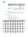
WL100-2Xxx
2x
Sensing range
(with reflector
PL80A)
Schaltab‐
stand (mit
Reflektor
PL80A)
Portée (avec
réflecteur
PL80A)
Distância de
comutação
(com refletor
PL80A)
Distanza di
commuta‐
zione (con rif‐
lettore
PL80A)
Distancia de
conmutación
(con reflector
PL80A)
开关距离
(带反射器
PL80A)
最大検出範
囲
0.01 ... 2.5 m
Sensing range
max. (with
reflector
PL80A)
Schaltab‐
stand max.
(mit Reflektor
PL80A)
Portée max.
(avec réflec‐
teur PL80A)
Distância de
comutação
máx. (com
refletor
PL80A)
Distanza
max. di com‐
mutazione
(con riflettore
PL80A)
Distancia de
conmutación
máx. (con
reflector
PL80A)
最大开关距
离(带反射
器 PL80A)
最大検出範
囲(リフレ
クタを用い
た場合
PL80A)
0.01 ... 3.0 m
Light spot dia‐
meter/
distance
Lichtfleck‐
durchmes‐
ser/Entfer‐
nung
Diamètre
spot / dis‐
tance
Diâmetro do
ponto de luz/
distância
Diametro
punto lumi‐
noso/
distanza
Diámetro del
punto lumi‐
noso/distan‐
cia
光斑直径/距
离
光点のスポ
ット径/距離
140 mm / 2
m
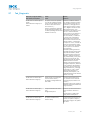
Supply voltage
U
v
Versorgungs‐
spannung U
V
Tension d'ali‐
mentation U
V
Tensão de ali‐
mentação U
V
Tensione di
alimenta‐
zione U
V
Tensión de
alimentación
U
V
供电电压 U
V
供給電圧 U
v
DC 10 ... 30
V
1)
Output current
I
max.
Ausgangs‐
strom I
max.
Courant de
sortie I
max.
Corrente de
saída I
max.
Corrente di
uscita I
max.
Intensidad de
salida I
max.
输出电流
I
max.
出力電流
I
max.
100 mA
Max. switching
frequency
Schaltfolge
max.
Commutation
max.
Sequência
máx. de
comutação
Sequenza di
commuta‐
zione max.
Secuencia de
conmutación
máx.
最大开关操
作顺序
最大スイッ
チング周波
数
1.000 Hz
2)
Демонтаж и утилизация
43
8017526 | SICK

WL100-2Xxx
2x
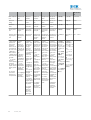
Max. response
time
Ansprechzeit
max.
Temps de
réponse
Tempo de
resposta
Tempo di rea‐
zione
Tiempo de
respuesta
响应时间 応答時間 ≤ 0.5 ms
3)
Enclosure
rating
Schutzart Indice de pro‐
tection
Tipo de prote‐
ção
Tipo di prote‐
zione
Tipo de pro‐
tección
防护类型 保護等級 IP 67
Protection
class
Schutzklasse Classe de
protection
Classe de
proteção
Classe di pro‐
tezione
Clase de pro‐
tección
防护等级 保護クラス III
Circuit protec‐
tion
Schutzschal‐
tungen
Protections
électriques
Circuitos de
proteção
Commutazi‐
oni di prote‐
zione
Circuitos de
protección
保护电路 回路保護 A,B,D
4)
Ambient opera‐
ting tempera‐
ture
Betriebsum‐
gebungstem‐
peratur
Température
de service
Temperatura
ambiente de
funciona‐
mento
Temperatura
ambientale di
funziona‐
mento
Temperatura
ambiente de
servicio
工作环境温
度
周辺温度 (作
動中)
-25 ... +55°C
1)
Limit value:
operation in
short-circuit
protection
mains max. 8
A; residual rip‐
ple max. 5 Vss
2)
With light /
dark ratio 1:1
3)
Signal transit
time with resis‐
tive load
4)
A = UV-con‐
nections
reverse polarity
protected
B = inputs and
output reverse-
polarity protec‐
ted
D = outputs
overcurrent
and short-cir‐
cuit protected
1)
Grenz‐
werte:
Betrieb im
kurzschluss‐
geschützten
Netz max. 8
A; Restwellig‐
keit max. 5
Vss
2)
Mit Hell- /
Dunkelver‐
hältnis 1:1
3)
Signallauf‐
zeit bei ohm‐
scher Last
4)
A = UV-
Anschlüsse
verpolsicher
B = Ein- und
Ausgänge
verpolsicher
D = Ausgänge
überstrom-
und kurz‐
schlussfest
1)
Valeurs
limites : fonc‐
tionnement
sur réseau
protégé
contre les
courts-cir‐
cuits max. 8
A ; ondulation
résiduelle
max. 5 Vcc
2)
Pour un
rapport clair/
sombre de
1:1
3)
Temps de
propagation
du signal sur
charge ohmi‐
que
4)
A = raccor‐
dements UV
protégés
contre les
inversions de
polarité
B = entrées
et sorties pro‐
tégées contre
les inversions
de polarité
D = sorties
protégées
contre les
courts-cir‐
cuits et les
surcharges
1)
Valores
limite: funcio‐
namento com
rede à prova
de curto-cir‐
cuito máx. 8
A; ondulação
residual máx.
5 Vss
2)
Com pro‐
porção
sombra/luz
1:1
3)
Tempo de
funciona‐
mento do
sinal com
carga ôhmica
4)
A = cone‐
xões protegi‐
das contra
inversão de
pólos UV
B = Entradas
e saídas pro‐
tegidas
contra polari‐
dade inversa
D = Saídas
protegidas
contra sobre‐
corrente e
curto-circuito
1)
Valori
limite: funzio‐
namento in
rete protetta
da cortocir‐
cuito max. 8
A; ondula‐
zione residua
max. 5 Vss
2)
Con rap‐
porto chiaro /
scuro 1:1
3)
Durata seg‐
nale con
carico ohmico
4)
A = UV-
Allacciamenti
protetti dall‐
'inversione di
polarità
B = entrate e
uscite pro‐
tette da pola‐
rità inversa
D = uscite
protette da
sovracorrente
e da cortocir‐
cuito.
1)
Valores
límite: funcio‐
namiento en
red protegida
contra corto‐
circuitos máx.
8 A; ondula‐
ción residual
máx. 5 Vss
2)
Con una
relación
claro/oscuro
de 1:1
3)
Duración
de la señal
con carga
óhmica
4)
Conexiones
A = UV prote‐
gidas contra
polarización
inversa
B = Entradas
y salidas pro‐
tegidas
contra polari‐
zación incor‐
recta
D=Salidas a
prueba de
sobrecorri‐
ente y corto‐
circuitos.
1)
极限值:
在防短路电
网中运行,
最大 8 A;最
大余波 5 Vss
2)
明暗比为
1:1
3)
信号传输
时间(电阻
负载时)
4)
A = UV 接
口(已采取
反极性保护
措施)
B = 具有反极
性保护的输
入端和输出
端
D = 抗过载电
流和抗短路
输出端
1)
限界値:
短絡保護の
操作は最大 8
A;残留リッ
プルは最大 5
Vss
2)
ライト/ダ
ークの比率
1:1
3)
A = UV 接
続は逆接保
護
B = 入力およ
び出力は逆
接保護
D = 出力過電
流および短
絡保護
44
8017526 | SICK
-
 1
1
-
 2
2
-
 3
3
-
 4
4
-
 5
5
-
 6
6
-
 7
7
-
 8
8
-
 9
9
-
 10
10
-
 11
11
-
 12
12
-
 13
13
-
 14
14
-
 15
15
-
 16
16
-
 17
17
-
 18
18
-
 19
19
-
 20
20
-
 21
21
-
 22
22
-
 23
23
-
 24
24
-
 25
25
-
 26
26
-
 27
27
-
 28
28
-
 29
29
-
 30
30
-
 31
31
-
 32
32
-
 33
33
-
 34
34
-
 35
35
-
 36
36
-
 37
37
-
 38
38
-
 39
39
-
 40
40
-
 41
41
-
 42
42
-
 43
43
-
 44
44
-
 45
45


SICK WL100-2 for transparent objects Instrucciones de operación
- Tipo
- Instrucciones de operación
en otros idiomas
- français: SICK WL100-2 for transparent objects Mode d'emploi
- italiano: SICK WL100-2 for transparent objects Istruzioni per l'uso
- English: SICK WL100-2 for transparent objects Operating instructions
- português: SICK WL100-2 for transparent objects Instruções de operação
- 日本語: SICK WL100-2 for transparent objects 取扱説明書
Artículos relacionados
-
SICK GRL18 Instrucciones de operación
-
-
-
-
-
-
-
-
-