
#@@79:=5C6?*@D?#R>6C@56?:P@D81CD1
":?*D6/@?6
H
/@?256FD@>O?:>2
H
(6E:>
,H
!H:>6?D:@?6D56=;F68@
45
1>38?H45<1B7?H451<D?
DEF:=5:?8):>68B):6>A@562C>25@6DE:>25@
8?B1C
(G9>7Q#Q(<945Q1B25BBIB9F5Q1>5CF9<<5,9C3?>C9>
+9C9D?EBG52C9D51D GGGCG9>7>C<9453?= ?B31<<EC1D
+9C9D5>E5CDB?C9D9?G525>GGGCG9>7>C<9453?=?<<K=5>?C1<
(("!.#()'*)$#(
#()'*$#(#("!
)@C68:DE6CJ@FCAC@5F4EG:D:E
%2C2C68:DEC2CDFAC@5F4E@G:D:E6
9EEAHHHDH:?8?D=:564@>
$D85B25>569DC9>3<E459>6?B=1D9?>?>@B?4E3DG1BB1>D95C1CC5=2<I@<1>E@41D5C:?9>9>7?EB=19<9>7<9CD6?B>5G
@B?4E3DC1>4@B?=?D9?>CB5359F9>7?EB>5GC<5DD5B1>4@B?F949>76554213;?>@B?4E3DC
(59>3<EI5>?DB?C25>56939?C3?=?9>6?B=139O>C?2B5<1C71B1>DM1C45<@B?4E3D?13DE1<9J139?>5C45<@<1>455>C1=2<1:5E>9BC51
>E5CDB1<9CD1453?BB5?@1B1>E5F?C@B?4E3D?CI@B?=?39?>5CB53929B>E5CDB?2?<5DM>45>?D9391CI@B?@?B39?>1B3?=5>D1B9?CC?2B5
<?C@B?4E3D?C
"%$')#)
S"%$')#)
%!('$'###(("!-
T!#)($"#.'!#("!
%<51C5=1;5CEB51<<<E=25B81B4G1B51>41335CC?BI@1BDC1B5133?E>D546?B6I?E1B5=9CC9>71>ID89>7@<51C5
$
#$)')*'#
D?D85CD?B5G85B5@EB381C54%<51C531<<?EBECD?=5B(5BF9355@1BD=5>D1DD85>E=25B25<?G
C57PB5C545AE5D?41C<1C@95J1C45=145B1<?C85BB1:5CI<?C1335C?B9?C5CDL>9>3<E94?C(961<D11<7?
#$
+*!+! )
1<1D95>414?>45<?3?=@BO!<1=51>E5CDB?5@1BD1=5>D?45(5BF939?1<<95>D51<>P=5B?AE5
1@1B535121:?
Minimum Use Zone
Zona de uso mínima
%
(!#-!*"'($!(%')!.
#$)*#)(#$)$"%!),)$*)
(!#()!!(($,#
!)$$W#.!(%/("'T-T
(+##%$'(%'$
#$)!2F?:525?@6DEM4@>A=6E2D:?%$()+
:?DE2=25@4@>@D6>F6DEC2

Installation Safety – Have You:
Consulted the assembly instructions supplied with your particular model?
Noted this accessory is to be used only on Swing•N•Slide approved designs? (Do not alter its design or add/remove components.)
Made sure all hardware is tightened securely? (Supplied bolt covers must also be fastened securely.)
Using a hacksaw, cut off all protruding threaded ends of bolts and other fasteners and remove any sharp edges with
a metal file as needed, and coated fastener ends with lead free paint?
Placed the equipment on level ground, not less than six feet (1.8 meters) from any structure or obstruction such as a fence, garage,
house, overhanging branches, laundry lines, or electrical wires?
Made sure home playground equipment is not installed over concrete, asphalt, packed earth or any other hard surface? (A fall onto
a hard surface can result in serious injury to the equipment user.)
Verified that suspended climbing ropes, chain,or cable are securely anchored at both ends and cannot be looped back unpon itself?
Consulted in assembly instructions of your particular model for minimum use zones?
Used a water sealant on your play set to protect the wood and prevent cracking and warping?
Followed all anchoring and shock absorbing surfacing requirements on the back of this sheet as they apply?
Made sure not to allow children to use equipment until it is properly installed?
Made sure to adjust all swings so there is a minimum 8'' clearance between the swing and the ground surface?
Operating Safety – Have You:
Determined that on-site adult supervision is provided for children of all ages?
Warned children the following before allowing them to use the equipment?
Not to walk close to, in front of, behind or between moving items.
Not to twist swing or any other accessory chains or ropes or loop them over the top support bar since this will reduce the
strength of chain or rope.
Not to swing empty seats or other accessories.
Not to slide down swing chains.
Be sure to sit in the center of the swing seat and other accessories with full weight on the seat.
Not to attach items to the playground equipment that are not specifically designed for use with the equipment such as but not
limited to, jump ropes, clotheslines, pet leashes, cables and chain. They may cause a strangulation hazard.
Not to climb or walk on the top of swing beams, railings or roof.
Not to use equipment in a manner other than intended.
Not to get off equipment while it is in motion.
Not to climb on the equipment when it is wet.
Be sure to go down slides feet first.
Determined that only one child per planned occupant seat should be allowed on this set at one time.
Determined children must be dressed appropriately for play. Avoid hooded jackets, bicycle or other sports helmets, clothing with
draw strings and loose fitting clothes which could become entangled or snagged on equipment.
Determined that suspended climbing ropes, chain, or cable are securely anchored at both ends and cannot be looped back upon
itself.
Made certain the slide is placed so that is is not in direct sunlight.
Safety Maintenance – Follow these preventive maintenance instructions at the intervals required:
To prevent the deterioration of materials, remove plastic swing seats and other plastic accessories when outdoors temp dips down to
or below 32° F and take indoors. Reinstall these plastic elements at the beginning of each play season.
At the beginning of each play season check metal parts for rust. If found, sand and repaint using a non lead-based paint meeting the
requirements of 16 CFR 1303 or SOR/2005-109.
At the beginning of each play season and once a month during each play season, check all moving parts for wear, rust or other
deterioration. Replace as needed. If any of these conditions exist, call 1-800-888-1232 to order replacement accessories.
At the beginning of each play season and once a month during each play season lubricate metallic moving parts.
At the beginning of each play season and twice a month during each play season, check all protective coverings on bolts, pipes,
edges, and corners. Replace if they are loose, cracked, or missing.
At the beginning of each play season and twice a month during each play season, rake and check depth of loose fill protective
surfacing material to prevent compaction and maintain appropriate depth. Replace as necessary.
At the beginning of each play season and twice a month during each play season tighten all hardware.
At the beginning of each play season and twice a month during each play season, check all wood members for deterioration and
splinters. Sand down splinters and replace deteriorating wood members.
Disposal Instructions
When the equipment is taken out of service, it must be disassembled and disposed of in such a way that no unreasonable hazards will exist at
the time the set is discarded.
Important!
Additional Safety Instructions for all Swing-N-Slide Playground Equipment.
Save this instruction sheet in the event the manufacturer needs to be contacted.
Observing the following statements and warnings reduces the likelihood of serious or fatal injury
Safety Checklist for Swing-N-Slide Play Sets and Accessories

This product is intended for single family home/residential use only and not intended for use in any public setting.
Placement in any public setting constitutes a misuse of this product.
IMPORTANT!
ADDITIONAL REQUIRED SAFETY INSTALLATION INSTRUCTIONS
According to ASTM requirements, all kits must be anchored to the ground and, if the unit has a climbing rope, the rope end must be anchored to the ground. If soil conditions
permit stakes to be pulled out easily, cementing into ground is necessary.
• To anchor the unit to the ground, Follow the instructions included in this plan for applying Anchor-It devices to your unit, or use 2" x 4" x 18" (45mm x 95mm x 457mm) pressure-
treated stakes. Pound stakes into ground at least 12" (305mm) at all inside corners of the posts (including A-frame legs and climbing unit posts). Attach with four (4) 16D (3-1/2")
galvanized nails per stake into each tower and/or A-frame upright.
• If the unit has a climbing rope, securely anchor the rope at both ends.
• Once the unit is completely assembled and before children are allowed to play on it, proper shock-absorbing surfacing material must be installed. This may be accomplished by
using loose-fill materials at a sufficient depth. The Consumer Product Safety Commission “Handbook for Public Playground Safety” lists the following materials and required
depths that are sufficient for home/residential application. Supplemental information may be found in ASTM F1292. For fall height protection up to 9 ft. (2.742m) [recommended
for Swing•N•Slide kits]:
LOOSE FILL MATERIAL REQUIRED (UNCOMPRESSED) DEPTH
1
in. (mm)
Wood Mulch 9" (229mm)
Double Shredded Bark Mulch 9" (229mm)
Uniform Wood Chips 12" (305mm)
These depths were derived from the CPSC Handbook. Swing•N•Slide has not done independent tests to determine these required depths.
When properly installed, shock absorbing material will completely cover the horizontal baseboards on climbing units. This protective surfacing must extend a minimum of 6 ft.
(1.828m) in all directions from the perimeter of the equipment or from the outermost edges of any component. For example, a slide extending beyond the platform must have
protective surfacing at least 6 ft. (1.828mm) out from both sides as well as the end. For swings, the protective surface must extend at least 14 ft. (6m)
out from both the back and
front of the swing when the swing is in its rest position.
Swing-N-Slide® MANUFACTURERS LIMITED WARRANTY
Swing-N-Slide® takes great pride in the quality and durability of our products. Our Manufacturer’s Limited Warranty provides confidence and demonstrates our commitment
to providing quality residential playground products.
MANUFACTURER’S LIFETIME LIMITED WARRANTY
Swing-N-Slide® warrants its thermoformed slides and climbing mountains to be free from defects in workmanship and materials, under normal use and conditions, for the
lifetime of the product.
MANUFACTURER’S 5 YEAR LIMITED WARRANTY
Swing-N-Slide® warrants its Custom Ready-to-Build Play Set kits and accessories to be free from defects in workmanship and materials, under normal use and conditions,
for a period of 5 years.
MANUFACTURER’S 5 YEAR LIMITED WARRANTY
Swing-N-Slide® warrants its No-Cut and Wood Complete Ready-to-Assemble Play Set kits against wood rot and termite damage, and to be free from defects in
workmanship and materials, under normal use and conditions, for a period of 5 years for structural wood components.
Cosmetic defects that do not affect the structural integrity of the product, or natural defects of wood such as warping, splitting, checking, twisting, shrinkage, swelling or
any other physical properties of wood that do not present a safety hazard, are not covered by this warranty.
MANUFACTURER’S ONE YEAR WARRANTY
Swing-N-Slide® warrants its canopy roofs and/or tarps, and Timber GLOVE lumber wrap to be free from defects in workmanship and materials, under normal use and
conditions, for a period of one year.
Swing-N-Slide® will repair, or at its discretion, replace any part within the stated warranty period which is defective in workmanship or materials. This decision is subject
to verification of the defect upon delivery of the defective part to Swing-N-Slide® at 1212 Barberry Drive, Janesville, Wisconsin, 53545. Any part(s) returned to Swing-N-
Slide® must have prior approved Return Authorization Number and proof of purchase, including the date of purchase. This warranty is valid only if the product is used for
the purpose for which it was designed and installed at a residential, single family dwelling. This warranty is void if the product is put to commercial or institutional use. This
warranty does not cover (a) products which have been damaged by acts of Nature, negligence, misuse, or accident, or which have been modified or repaired by
unauthorized persons; (b) the cost of labor; or the cost of shipping the product, any part, or any replacement product or part.
Swing-N-Slide® DISCLAIMS ALL OTHER REPRESENTATIONS AND WARRANTIES OF ANY KIND, EXPRESS, IMPLIED, STATUTORY OR OTHERWISE, INCLUDING THE
IMPLIED WARRANTIES OF MERCHANTIBILITY AND FITNESS FOR A PARTICULAR PURPOSE. Swing-N-Slide® WILL NOT BE LIABLE FOR ANY INCIDENTAL OR
CONSEQUENTIAL DAMAGES. This warranty is non-transferable and does not extend to the owners of the product subsequent to the original purchaser. Some states do not
allow limitations on implied warranties or exclusion of incidental or consequential damages, so these restrictions may not be applicable to you. This warranty gives you
specific legal rights. You may also have other rights, which vary from state to state.
This warranty also does not apply to:
• Structures not erected, maintained or inspected in conformance with Swing-N-Slide® installation plans
• Structures that have had parts added or substituted not in conformance with Swing-N-Slide® installation plans
• Parts that have been modified, altered or misused
• Parts that have not been used as designed or intended
• Damage due to acts of Nature, vandalism, abnormal use or abuse as determined by Swing-N-Slide®
@C7FCE96C:?7@C>2E:@?@?A=2J8C@F?5D276EJ
D85?>CE=5B%B?4E3D(165DI?==9CC9?>
%(@E2<9C85CD85$ED4??B?=5%<1I7B?E>4(165DI1>42??;G893831>254?G><?14546?B6B55
6B?=HHH4AD48@G>1449D9?>1<B5C?EB359CD85=5B931>(?395DI?6)5CD9>71>4"1D5B91<C()"
(D1>41B4?>CE=5B(165DI%5B6?B=1>35(@5396931D9?>6?B?=5%<1I7B?E>4AE9@=5>D()"
G893831>25@EB381C541>44?G><?14546B?=HHH2DE>@C8

Assembly
Seguridad durante la instalación – Usted:
¿Ha consultado las instrucciones de ensamblaje suministradas con su modelo en particular?
¿Ha notado que este accesorio se debe usar solamente con diseños aprobados por Swing•N•Slide? (No altere su diseño ni añada/retire componentes).
¿Se ha asegurado de que todos los accesorios hayan sido ajustados firmemente? (Las cubiertas de los pernos suministradas también se deben
asegurar firmemente).
¿Se ha asegurado de cortar con una sierra de mano todos los extremos roscados sobresalientes de los pernos y demás sujetadores, así como de haber eliminado
cualquier borde filoso usando una lima para metales, según haya sido necesario, y recubierto los extremos de los sujetadores con pintura sin plomo?
¿Ha colocado el equipo a nivel del piso, a no menos de seis pies (1.8 metros) de cualquier estructura u obstrucción tal como una cerca, garaje, casa,
ramas colgantes, sogas para tender la ropa o cables eléctricos?
¿Se ha asegurado de que el equipo de juego no haya sido instalado sobre concreto, asfalto, tierra prensada o cualquier otra superficie dura?
(Una caída sobre una superficie dura puede provocar una lesión grave al usuario del equipo).
¿Ha verificado que las cuerdas para escalar, la cadena o el cable suspendidos estén sujetados en ambos extremos?
¿Ha consultado las zonas mínimas de uso en las instrucciones de ensamblaje de su modelo en particular?
¿Ha usado un sellador de agua en su conjunto de juego para proteger la madera y prevenir que se agriete y se tuerza?
¿Ha seguido todos los requisitos que se encuentran en el reverso de esta página relacionados con el anclaje y el recubrimiento amortiguador de golpes,
según corresponda?
¿Se ha asegurado de no permitir que los niños usen los equipos hasta que éstos queden correctamente instalados?
¿Se ha asegurado de ajustar todos los columpios de manera que haya un espacio mínimo de 8'' entre el columpio y la superficie del suelo?
Seguridad durante la operación – Usted:
¿Se ha asegurado de que en el sitio de juegos haya supervisión por parte de un adulto para los niños de todas las edades?
Antes de permitirles usar los equipos, ¿les ha enseñado a los niños lo siguiente? No caminar cerca, enfrente, por detrás o entre objetos móviles.
No retorcer el columpio ni cualquiera de las cadenas o cuerdas accesorias ni enrollarlas sobre la barra de soporte superior, ya que esto reduciría la
fuerza de la cadena o la cuerda.
No columpiar los asientos vacíos u otros accesorios.
No deslizarse hacia abajo por las cadenas de los columpios.
Asegurarse de sentarse en el centro del columpio y en los otros accesorios, con todo el peso sobre el asiento.
No unir accesorios al equipo de juego que no estén diseñados específicamente para el mismo, como los siguientes, entre otros: cuerdas para saltar,
sogas para tender la ropa, correas para mascotas, cables y cadenas. Éstos pueden provocar peligro de estrangulamiento.
No trepar ni caminar sobre la parte superior de las vigas de los columpios, los pasamanos o el techo.
No usar los equipos de manera diferente a aquella para la cual fueron diseñados.
No saltar de los equipos cuando están en movimiento.
No subirse a los equipos cuando estén mojados.
Asegurarse de bajar por los toboganes con los pies por delante.
¿Ha determinado que sólo se puede permitir un niño por asiento en un mismo momento?
¿Has determinado que los niños deben estar vestidos en forma adecuada para el juego? Evita chaquetas con capucha, cascos para bicicletas u otros
deportes, ropa con cordones y suelta que podría hacer que se enreden o se enganchen en el equipo.
¿Has determinado que las sogas, cadenas o cables para escalar están anclados firmemente en ambos extremos y no pueden entrelazarse?
¿Se ha asegurado de que el tobogán se ubique de manera que no esté bajo la luz directa del sol?
Mantenimiento de Seguridad–Sigue estas instrucciones preventivas de mantenimiento en los intervalos
requeridos:
Para evitar el deterioro de los materiales, retira los asientos de plástico de los columpios y otros accesorios de plástico cuando la temperatura exterior
baje a 32° F o menos y llévalos a un lugar bajo techado. Reinstala estos elementos plásticos al inicio de cada temporada de juego.
Al inicio de cada temporada de juego verifica que las piezas de metal no se hayan oxidado. Si se encuentran indicios de corrosión, lija y vuelve a pintar
usando una pintura que no sea a base de plomo y que cumpla con los requisitos 16 CFR 1303 o SOR/2005-109.
Al inicio de cada temporada de juego y una vez al mes durante la misma, verifica que las piezas movibles no se hayan desgastado, oxidado o
deteriorado de otra manera. Reemplázala si es necesario. Si existe alguna de estas condiciones, llama al 1-800-888-1232 para ordenar los accesorios de
repuesto.
Al inicio de cada temporada de juego y una vez al mes durante la misma, lubrica las piezas de metal en movimiento.
Al inicio de cada temporada de juego y dos veces al mes durante la misma, revisa todas las cubiertas protectores de pernos, tubos, bordes y esquinas.
Reemplázalas si están sueltas, rotas o si faltan.
Al inicio de cada temporada de juego y dos veces al mes durante la misma, rastrilla y verifica la profundidad del material protector de relleno de superficies
para que no esté flojo, evitar la compactación y mantener la profundidad adecuada. Reemplaza según sea necesario.
Al inicio de cada temporada de juego y dos veces al mes durante la misma, ajusta todos los herrajes.
Al inicio de cada temporada de juego y una vez al mes durante misma, verifica que las piezas de madera no estén deterioradas y astilladas. Lija las
astilladuras y reemplaza las partes de madera deterioradas.
Instrucciones de desecho
Cuando el equipo sea retirado de servicio, se debe desarmar y desechar de tal manera que no presente peligros no razonables al momento de desecharlo.
¡Importante!
Instrucciones de seguridad adicionales para todos los equipos de juego Swing-N-Slide.
Guardar esta hoja de instrucciones en caso de que se requiera contactar al fabricante.
Atender los siguientes enunciados y advertencias reduce la posibilidad de lesiones graves o fatales.
Lista de control de seguridad para los juegos y accesorios Swing-N-Slide

Este producto ha sido ideado para su uso en una residencia u hogar de una sola familia y no para usarse en lugares públicos.
Su uso en lugares públicos constituye una mala utilización de este producto.
¡IMPORTANTE!
INSTRUCCIONES ADICIONALES DE SEGURIDAD PARA LA INSTALACIÓN
Según establece la Sociedad Americana de Pruebas y Materiales (American Society for Testing and Materials, ASTM), todos los equipos deben anclarse al suelo y, si la unidad tiene además una cuerda
para escalar, el extremo de la cuerda deberá anclarse al suelo. Si las condiciones del terreno permiten que las estacas se salgan con facilidad, será entonces necesario cementarlas al suelo.
• Para anclar la unidad al suelo, siga las instrucciones contenidas en el presente plan para aplicar los dispositivos de anclaje a su unidad, o utilice estacas tratadas a presión de 2" x 4" x
18"(45mm x 95mm x 457mm). Martille las estacas en el suelo a una profundidad de al menos 12" (305 mm) en todas las esquinas internas de los postes (incluidas las patas del marco en A y
los postes de la unidad para escalar). Fije con cuatro (4) clavos galvanizados de 16D (3-1/2") por estaca en cada poste de la torre y/o del marco en “A”.
• Si la unidad incluye una soga para escalar, ancla la soga en ambos extremos.
• Una vez que la unidad esté completamente armada y antes de que se le permita a los niños jugar en ella, se debe instalar una superficie de material adecuado para
amortiguar golpes. Esto se consigue usando materiales de relleno suelto a una profundidad adecuada. La “Guía para la seguridad en las zonas de recreo públicas” (Handbook for Public
Playground Safety) publicada por la Comisión de Seguridad para los Productos de Consumo (Consumer Product Safety Commission, CPSC) cita los siguientes materiales y las profundidades
requeridas que se consideran suficientes para uso en residencias y hogares. Información adicional puede encontrarse en ASTM F1292.Para protegerse de caídas de hasta 9 pies (2.742m) de
altura [recomendado para los equipos Swing•N•Slide]:
MATERIALES DE RELLENO SUELTO PROFUNDIDAD (SIN COMPRIMIR) REQUERIDA
1
pulgada (mm)
Mantillo de madera 9" (229 mm)
Mantillo de corteza de doble trituración 9" (229 mm)
Viruta de madera uniforme 12" (305 mm)
Estas profundidades se han extraído de la Guía de la CPSC. Swing•N•Slide no ha realizado estudios independientes para determinar estas profundidades recomendadas.
Cuando el material para amortiguar golpes se instala adecuadamente, éste cubre completamente todas las superficies horizontales de las unidades para escalar. Esta superficie protectora
deberá extenderse al menos 6 pies (1.828mm) en todas las direcciones, desde el perímetro del equipo o desde los bordes externos de cualquiera de los componentes. Por ejemplo, un
tobogán que se extiende por fuera de la plataforma deberá tener una superficie protectora de al menos 6 pies (1.828mm) a ambos lados y en el extremo. Para columpios, la superficie
protectora se debe extender por lo menos
14 pies (6 m) a partir de tanto la parte trasera
como
delantera del columpio cuando éste se encuentre en posición de reposo.
GARANTÍA LIMITADA DEL FABRICANTE DE Swing-N-Slide
®
Swing-N-Slide® se enorgullece de la calidad y la durabilidad de nuestros productos. Nuestra garantía limitada del fabricante ofrece confianza y demuestra
nuestro compromiso con la entrega de productos de calidad para zonas de recreo residenciales.
GARANTÍA LIMITADA DE POR VIDA DEL FABRICANTE
Swing-N-Slide® garantiza que sus toboganes termoformados y montañas para escalar estarán libres de defectos de mano de obra y materiales, bajo condiciones y
uso normales, durante la vida útil del producto.
GARANTÍA LIMITADA DE 5 AÑOS DEL FABRICANTE
Swing-N-Slide® garantiza que sus kits de conjunto de juegos personalizados listos para armar y sus accesorios permanecerán libres de defectos de mano de
obra y materiales, bajo condiciones y uso normales, durante un período de 5 años.
GARANTÍA LIMITADA DE 5 AÑOS DEL FABRICANTE
Swing-N-Slide® garantiza que sus kits de conjunto de juegos No-Cut and Wood Complete Ready-to-Assemble Play Set no experimentarán deterioro debido
a putrefacción de la madera o termitas, y que permanecerán libres de defectos de mano de obra y materiales, bajo condiciones y uso normales, durante un
período de 5 años en el caso de los componentes estructurales de madera.
Los defectos estéticos que no afecten la integridad estructural del producto o los defectos naturales de la madera como la torsión, la rajadura, la fisuración, el
pandeo, contracción, hinchamiento o cualquier otra propiedad física de la madera que no presente un riesgo de seguridad, no están cubiertos por esta garantía.
GARANTÍA DE UN AÑO DEL FABRICANTE
Swing-N-Slide® garantiza que sus techos y/o lonas impermeabilizadas de cubierta y envoltura para madera Timber-GLOVE permanecerán libres de defectos de
mano de obra y materiales, bajo condiciones y uso normales, durante un período de un año.
Swing-N-Slide® reparará, o según su criterio, reemplazará, dentro del período de garantía señalado, cualquier pieza que presente defectos de mano de obra o
materiales. Esta decisión está sujeta a verificación del defecto luego del envío de la pieza defectuosa a Swing-N-Slide® a 1212 Barberry Drive, Janesville,
Wisconsin, 53545. Toda pieza devuelta a Swing-N-Slide® primero debe tener un Número de autorización de devolución aprobado y una prueba de compra,
incluida la fecha de compra. Esta garantía es válida sólo si el producto se utiliza para el objetivo que se diseñó y se instala en una vivienda unifamiliar residencial.
Esta garantía queda nula si al producto se le da un uso comercial o institucional. Esta garantía no cubre (a) productos que hayan sido dañados por hechos de la
naturaleza, negligencia, uso indebido o accidente, o que hayan sido modificados o reparados por personas no autorizadas; (b) el costo de la mano de obra o el
costo de envío del producto, alguna pieza o un producto o pieza de reemplazo.
Swing-N-Slide® DESCONOCE TODAS LAS DEMÁS DECLARACIONES Y GARANTÍAS DE CUALQUIER TIPO, EXPRESAS, IMPLÍCITAS, ESTATUTARIAS U OTRAS,
INCLUIDAS LAS GARANTÍAS IMPLÍCITAS DE COMERCIABILIDAD Y APTITUD PARA UN FIN ESPECÍFICO. Swing-N-Slide® NO SERÁ RESPONSABLE DE NINGÚN DAÑO
FORTUITO O CONSECUENTE. Esta garantía no es transferible y no se extiende a los propietarios del producto posteriores al comprador original. Algunos estados
no permiten limitaciones en las garantías implícitas ni la exclusión de daños fortuitos o consecuentes, por tanto es posible que estas restricciones no se apliquen
en su caso. Esta garantía le otorga derechos legales específicos. Es posible que tenga otros derechos, que pueden variar de un estado a otro.
Esta garantía tampoco se aplica a:
• Estructuras no levantadas, mantenidas ni inspeccionadas en conformidad con los planos de instalación de Swing-N-Slide®
• Estructuras en las que se ha agregado o sustituido piezas que no están en conformidad con los planos de instalación de Swing-N-Slide®
• Piezas que se han modificado, alterado o usado indebidamente
• Piezas que no se han usado según su diseño u objetivo
• Daño debido a hechos de la naturaleza, vandalismo, uso anormal o abuso según lo determine Swing-N-Slide®
%2C2@3E6?6C:?7@C>24:Q?25:4:@?2=D@3C6D68FC:5256?=2DK@?2D56C64C6@
<1?=9C9O>45(57EB9414@1B1<?C%B?4E3D?C45
?>CE=??>CE=5B%B?4E3D(165DI?==9CC9?>%(@E2<9315<"1>E1<@1B1<1C57EB94145><1CJ?>1C45B53B5?4?=LCD931C1<19B5
<92B5$ED4??B?=5%<1I7B?E>4(165DI1>42??;AE5C5@E54545C31B71B5>6?B=17B1DE9D145HHH4AD48@G*>B53EBC?14939?>1<5C<1
C@539693139O>CDK>41B45'5>49=95>D?45<1(57EB941445<?>CE=94?B45<1(?39541445**45%BE521CI"1D5B91<5C()"
%1B1AE9@?C45%1D9?C45'53B5?5>5<?71B()"AE5C5@E54514AE9B9BI45C31B71B5>HHH2DE>@C8

TOOLS REQUIRED / HERRAMIENTAS REQUERIDAS
==C3B5GC
D?B>9<<?C45U==
6<1DG1C85BC
1B1>45<1C@<1>1C45U
6<1DG1C85BC
1B1>45<1C@<1>1C
45U
H 1BB9175?<DC
@5B>?C3?>3125J1458?>7?45UH
C3B5GC
D?B>9<<?C45U
H 1BB9175?<DC
@5B>?C3?>3125J1458?>7?45UH
!?3#EDC
DE5B31C45C57EB9414
,??4!?3,1C85BC
1B1>45<1C45C57EB9414@1B1
=145B1
!)''!!
)!'$!L)'$
""'
"')!!$
)%"(*'
#)"L)'
'%#)'((&*'
(*''%#)'$
TOOLS REQUIRED / HERRAMIENTAS REQUERIDAS
1-1/2’’ Hex Head Bolt
2’’ Hex Head Bolt
2-1/2’’ Hex Head Bolt
3-1/2’’ Hex Head Bolt
4-1/2’’ Hex Head Bolt
5-1/2’’ Hex Head Bolt
%!!%()
%*#)
()$'#!!$'%!!%(
($ ),'#
!!+.*$T
C:==:E
C@4256E2=25C@56T
*E:=:EJ ?:76
#2G2;2
<17C3B5G
D?B>9<<?C453?=@B5C9O>45U
!17(3B5G
D?B>9<<?C453?=@B5C9O>45U
C3B5GC
D?B>9<<?C45U
,??4(3B5G
D?B>9<<?C@1B1=145B145U
!?3,1C85
B1>45<145C57EB9414
,'#
!!+#!(
)1B@,1C85B
B1>45<1@<1>145
H 5H514?<D @5B>?C3?>3125J185H17?>1<45H
().!(((
*()"(
(%'$))$'(.
"W('#)%$!+$
(3B5GC#$)*(
)?B>9<<?C45#$(*)!.
@1>8514C3B5GC
D?B>9<<?C453125J1
B54?>411@<1>14145U
@1>8514C3B5GC
D?B>9<<?C453125J1B54?>41
1@<1>14145U
!17?<D
@5B>?C453?=@B5C9O>45U
)BECC(3B5G
D?B>9<<?C453125J1B54?>4145
%1>8514(3B5G
D?B>9<<?C453125J1B54?>41
1@<1>14145U

R
INTENDED FOR USE BY CHILDREN
FROM AGES 2-10 YEARS
FOR HOME / RESIDENTIAL USE
ONLY
DISEÑADO PARA SER USADO POR
NIÑOS ENTRE 2 Y 10 AÑOS DE
EDAD PARA USO EN EL
HOGAR/USO RESIDENCIAL
ÚNICAMENTE
RÉSERVÉ À L_UTILISATION PAR
DES ENFANTS DE 2 À 10 ANS
USAGE RÉSIDENTIEL/FAMILIAL
SEULEMENT
1212 Barberry Drive
Janesville, WI 53545
1-800-888-1232
www.swing-n-slide.com
#1=5%<1D5
@<13145945>D9693139O>
%<1>
@<1>?
.B1=5B13;5DC
12B1J145B1C45<15CDBE3DEB1.
PB 9240
Plan / Plano
PB 9240
)19<?BXC81<;
D9J145C1CDB5
(2) 4'' x 4'' Shelf-Loc
abrazaderas de estante de 4'' x 4''
(10) Wrap-Loc
abrazaderas de envoltura
(1) LH Split Beam bracket
abrazadera de viga dividida
izquierda
'!!)"9>
'$)!'$U=M>
(8) 2'' x 4'' Shelf-Loc
abrazaderas de estante de 2'' x 4''
"?>;5I1B'E>7C
@5<41N?C45<121BB1DB5@14?B145U
??=5B1>7B13;5D
12B1J145B1CD9@?V??=5B1>7W
(1) RH Split Beam bracket
abrazadera de viga dividida derecha
)1B@
)9=25B<?F5
)9=25B<?F545U
)9=25B<?F5
)9=25B<?F545U
'??6B13;5D
12B1J145B1C45D538?
))?BHR9D
2B?31))?BHR
))?BHR9D
2B?31))?BHR

Assembly Instructions / Instrucciones de ensamblaje
51FIEDI (G9>7(51D
H6:89E=:>:E <2C
1C95>D?C453?<E=@9?B5C9CD5>D5C
!O>:E656A6D@ U<2
(165DI1>4<5C
=1>9:1C45C57EB9414
<9=29>7'?3;C
@954B1C@1B15C31<1B
>38?BD
1>3<1:5C
>38?BD(DB1@C
3?BB51C451>3<1:5
HDB1EDI(G9>71>75BC
3?<7145B?C453?<E=@9?451<D1
B5C9CD5>391
?BE>
<2,5978D!9=9D
V?BE>W3?>1335C?B9?C
!M=9D545@5C?U<2
(D5@B13;5DC
!56D
12B1J145B1C45
@5<41N?
9JAE95B41C
(D5@B13;5DC
'978D
12B1J145B1C45
@5<41N?
45B5381C
!B13;5DC
12B1J145B1C5>V!W
&E93;!9>;C
C<12?>5CBK@94?C
?BE>(51D
C95>D?V?BE>W
?BE>1>4<5C
"1>9:1CV?BE>W
819>
145>1C9>B53E2B9=95>D?
45XX
?<D?F5BC
)1@1C45@5B>?
(G9>7
1>75BC
?<7145B?C45<
3?<E=@9?45
,5<4#ED
!?3,1C85B
B1>45<145C57EB9414
H5H514?<D
@5B>?C3?>3125J85H17?>1<45
==,1C85B
1B1>45<1C@<1>1C45U==
Washer 8mm
1/4 Washer
5/16 Washer
3/16 Washer
'51=B13;5D
(?@?BD5C'
!51=B13;5D
(?@?BD5C!
H5H514?<D
@5B>?C3?>3125J185H17?>1<45
#$)*(
#$(*)!.
H1BB9175?<DC
@5B>?C3?>3125J1458?>7?45U

#).#)%'$%'!*"'
#)Y#!"'*$
*D:?8E963@2C5=:DE2?5E967@==@H:?8:==FDEC2E:@?D:56?E:7JE963@2C5D7@CE96
2DD6>3=:6D:?J@FC<:E
*D@56=2=:DE256A=242DJ=2D:=FDEC24:@?6DD:8F:6?E6D:56?E:7:42C=2DE23=2D
A2C2=2D2D2>3=62D6?DF<:E
(@CEE963@2C5D3JD:K62?5DEJ=6
$C56?2C=2DE23=2DA@CE2>2P@J6DE:=@
7J@FD9@F=536>:DD:?82?J:E6>D4@?E24E4FDE@>6CD6CG:463JE96A9@?6
?F>36C@?E964@G6C@7E9:DA=2?
(:D672=E22=8R?2CEO4F=@AQ?82D66?4@?E24E@4@?6=D6CG:4:@2=4=:6?E6A@C6=
?R>6C@56E6=N7@?@6?=2A@CE252566DE6A=2?
$?46J@F92G62==@7J@FC<:E4@?E6?ED4@F?E652?52DD@CE65368:?2DD6>3=J
*?2G6KBF6E6?82E@5@D=@D4@?E6?:5@D56EF<:E4@?E25@JG2C:25@4@>6?K2C
6=>@?E2;6
SA 2893
PF 4312 1’’ x 5-3/8’’ x 36’’
PF 4345 5/4’’ x 6’’ x 40-1/4’’
PF 4356 5/4’’ x 6’’ x 43-13/16’’
PF 4315 5/4’’ x 6’’ x 43-13/16’’ SHINGLE
TEJAS
SA 2921
PF 4307 1’’ x 5-3/8’’ x 18-3/4’’ GABLE BOTTOM
GABLE INFERIOR
PF 4309 1’’ x 5-3/8’’ x 23-7/8’’
PF 4310 1’’ x 5-3/8’’ x 28’’
PF 4312 1’’ x 5-3/8’’ x 36’’
PF 4308 1’’ x 5-3/8’’ x 23’’ PICNIC TABLE
MESA DE PICNIC
PF 4313 1’’ x 5-3/8’’ x 40-1/4’’
PF 4325 5/4’’ x 6’’ x 45-1/4’’ BENCH SEAT
BANCO DEL ASIENTO
PF 4314 1’’ x 5-3/8’’ x 47-1/2’’ CENTER ARCH
CENTRO DE ARCO
PF 4327 5/4’’ x 6’’ x 47-1/2’’ A-FRAME SUPPORT
UN BASTIDOR DE SOPORTE
x5
x2
x4
x7
x2
x1
x4
x3
x3
x4
x1
x1
x2
Assembly Instructions / Instrucciones de ensamblaje
I
SA 2893
PF 4312 1’’ x 5-3/8’’ x 36’’
PF 4345 5/4’’ x 6’’ x 40-1/4’’
PF 4356 5/4’’ x 6’’ x 43-13/16’’
PF 4315 5/4’’ x 6’’ x 43-13/16’’ SHINGLE
TEJAS
SA 2921
PF 4307 1’’ x 5-3/8’’ x 18-3/4’’ GABLE BOTTOM
GABLE INFERIOR
PF 4309 1’’ x 5-3/8’’ x 23-7/8’’
PF 4310 1’’ x 5-3/8’’ x 28’’
PF 4312 1’’ x 5-3/8’’ x 36’’
PF 4308 1’’ x 5-3/8’’ x 23’’ PICNIC TABLE
MESA DE PICNIC
PF 4313 1’’ x 5-3/8’’ x 40-1/4’’
PF 4325 5/4’’ x 6’’ x 45-1/4’’ BENCH SEAT
BANCO DEL ASIENTO
PF 4314 1’’ x 5-3/8’’ x 47-1/2’’ CENTER ARCH
CENTRO DE ARCO
PF 4327 5/4’’ x 6’’ x 47-1/2’’ A-FRAME SUPPORT
UN BASTIDOR DE SOPORTE
x5
x2
x4
x7
x2
x1
x4
x3
x3
x4
x1
x1
x2

Assembly Instructions / Instrucciones de ensamblaje
SA 2893
PF 4312 1’’ x 5-3/8’’ x 36’’
PF 4345 5/4’’ x 6’’ x 40-1/4’’
PF 4356 5/4’’ x 6’’ x 43-13/16’’
PF 4315 5/4’’ x 6’’ x 43-13/16’’ SHINGLE
TEJAS
SA 2921
PF 4307 1’’ x 5-3/8’’ x 18-3/4’’ GABLE BOTTOM
GABLE INFERIOR
PF 4309 1’’ x 5-3/8’’ x 23-7/8’’
PF 4310 1’’ x 5-3/8’’ x 28’’
PF 4312 1’’ x 5-3/8’’ x 36’’
PF 4308 1’’ x 5-3/8’’ x 23’’ PICNIC TABLE
MESA DE PICNIC
PF 4313 1’’ x 5-3/8’’ x 40-1/4’’
PF 4325 5/4’’ x 6’’ x 45-1/4’’ BENCH SEAT
BANCO DEL ASIENTO
PF 4314 1’’ x 5-3/8’’ x 47-1/2’’ CENTER ARCH
CENTRO DE ARCO
PF 4327 5/4’’ x 6’’ x 47-1/2’’ A-FRAME SUPPORT
UN BASTIDOR DE SOPORTE
x5
x2
x4
x7
x2
x1
x4
x3
x3
x4
x1
x1
x2
SA 2922
SA 2923
PF 4309 1’’ x 5-3/8’’ x 23-7/8’’
PF 4310 1’’ x 5-3/8’’ x 28’’
PF 4324 5/4’’ x 6’’ x 30’’ CENTER ARCH
CENTRO DE ARCO
PF 4311 5/4’’ x 6’’ x 34-1/2’’ PICNIC TABLE
MESA DE PICNIC
PF 4312 1’’ x 5-3/8’’ x 36’’
PF 4313 1’’ x 5-3/8’’ x 40-1/4’’
PF 4356 5/4’’ x 6’’ x 43-13/16’’
PF 4348 5/4’’ x 6’’ x 47-1/2’’ OFFSET ARCH
COMPENSAR ARCO
PF 4326 5/4’’ x 6’’ x 47-1/2’’ CENTER ARCH
CENTRO DE ARCO
PF 4353 2’’ x 4’’ x 47-1/2’’
PF 4304 1’’ x 4’’ x 40-1/4’’
PF 4305 1’’ x 4’’ x 45-3/4’’
PF 4306 1’’ x 4’’ x 47-1/2’’
PF 4341 5/4’’ x 4’’ x 47-1/2’’
PF 4322 5/4’’ x 4’’ x 37-5/8’’
PF 4321 5/4’’ x 4’’ x 34-1/4’’
PF 4320 5/4’’ x 4’’ x 33-1/2’’ TARP ROOF A-FRAME
TOLDO DE TECHO A-FRAME
PF 4318 5/4’’ x 4’’ x 9’’
PF 4337 5/4’’ x 4’’ x 9’’ CHAMFER
CHAFLAN
x6
x3
x1
x1
x2
x4
x1
x1
x1
x3
x2
x1
x1
x1
x3
x1
x1
x1
x2

Assembly Instructions / Instrucciones de ensamblaje
SA 2924
SA 2925
PF 4309 1’’ x 5-3/8’’ x 23-7/8’’
PF 4330 2’’ x 4’’ x 30’’
PF 4317 1’’ x 2-1/2’’ x 26’’
PF 4303 1’’ x 4’’ x 28-1/4’’
PF 4339 5/4’’ x 4’’ x 20-3/4’’
PF 4328 1-1/2’’ x 1-1/2’’ x 22-3/4’’
PF 4338 1-1/2’’ x 1-1/2’’ x 17’’ SLIDE STAKE
DIAPOSITIVA JUEGO
PF 4337 5/4’’ x 4’’ x 9’’ CHAMFER
CHAFLAN
PF 4336 5/4’’ x 4’’ x 3-1/2’’ CHAMFER
CHAFLAN
PF 4282 2’’ x 4’’ x 20-3/8’’
PF 4355 2’’ x 4’’ x 20’’
PF 4329 2’’ x 4’’ x 22-3/4’’
PF 4319 5/4’’ x 4’’ x 30’’
PF 4302 1’’ x 4’’ x 28-1/8’’
PF 4303 1’’ x 4’’ x 28-1/4’’
PF 4320 5/4’’ x 4’’ x 33-1/2’’ TARP ROOF A-FRAME
TOLDO DE TECHO A-FRAME
x4
x3
x1
x1
x1
x1
x1
x1
x8
x3
x2
x1
x1
x2
x3
x1
SA 2922
SA 2923
PF 4309 1’’ x 5-3/8’’ x 23-7/8’’
PF 4310 1’’ x 5-3/8’’ x 28’’
PF 4324 5/4’’ x 6’’ x 30’’ CENTER ARCH
CENTRO DE ARCO
PF 4311 5/4’’ x 6’’ x 34-1/2’’ PICNIC TABLE
MESA DE PICNIC
PF 4312 1’’ x 5-3/8’’ x 36’’
PF 4313 1’’ x 5-3/8’’ x 40-1/4’’
PF 4356 5/4’’ x 6’’ x 43-13/16’’
PF 4348 5/4’’ x 6’’ x 47-1/2’’ OFFSET ARCH
COMPENSAR ARCO
PF 4326 5/4’’ x 6’’ x 47-1/2’’ CENTER ARCH
CENTRO DE ARCO
PF 4353 2’’ x 4’’ x 47-1/2’’
PF 4304 1’’ x 4’’ x 40-1/4’’
PF 4305 1’’ x 4’’ x 45-3/4’’
PF 4306 1’’ x 4’’ x 47-1/2’’
PF 4341 5/4’’ x 4’’ x 47-1/2’’
PF 4322 5/4’’ x 4’’ x 37-5/8’’
PF 4321 5/4’’ x 4’’ x 34-1/4’’
PF 4320 5/4’’ x 4’’ x 33-1/2’’ TARP ROOF A-FRAME
TOLDO DE TECHO A-FRAME
PF 4318 5/4’’ x 4’’ x 9’’
PF 4337 5/4’’ x 4’’ x 9’’ CHAMFER
CHAFLAN
x6
x3
x1
x1
x2
x4
x1
x1
x1
x3
x2
x1
x1
x1
x3
x1
x1
x1
x2
I
SA 2924
SA 2925
PF 4309 1’’ x 5-3/8’’ x 23-7/8’’
PF 4330 2’’ x 4’’ x 30’’
PF 4317 1’’ x 2-1/2’’ x 26’’
PF 4303 1’’ x 4’’ x 28-1/4’’
PF 4339 5/4’’ x 4’’ x 20-3/4’’
PF 4328 1-1/2’’ x 1-1/2’’ x 22-3/4’’
PF 4338 1-1/2’’ x 1-1/2’’ x 17’’ SLIDE STAKE
DIAPOSITIVA JUEGO
PF 4337 5/4’’ x 4’’ x 9’’ CHAMFER
CHAFLAN
PF 4336 5/4’’ x 4’’ x 3-1/2’’ CHAMFER
CHAFLAN
PF 4282 2’’ x 4’’ x 20-3/8’’
PF 4355 2’’ x 4’’ x 20’’
PF 4329 2’’ x 4’’ x 22-3/4’’
PF 4319 5/4’’ x 4’’ x 30’’
PF 4302 1’’ x 4’’ x 28-1/8’’
PF 4303 1’’ x 4’’ x 28-1/4’’
PF 4320 5/4’’ x 4’’ x 33-1/2’’ TARP ROOF A-FRAME
TOLDO DE TECHO A-FRAME
x4
x3
x1
x1
x1
x1
x1
x1
x8
x3
x2
x1
x1
x2
x3
x1

Assembly Instructions / Instrucciones de ensamblaje
SA 2924
SA 2925
PF 4309 1’’ x 5-3/8’’ x 23-7/8’’
PF 4330 2’’ x 4’’ x 30’’
PF 4317 1’’ x 2-1/2’’ x 26’’
PF 4303 1’’ x 4’’ x 28-1/4’’
PF 4339 5/4’’ x 4’’ x 20-3/4’’
PF 4328 1-1/2’’ x 1-1/2’’ x 22-3/4’’
PF 4338 1-1/2’’ x 1-1/2’’ x 17’’ SLIDE STAKE
DIAPOSITIVA JUEGO
PF 4337 5/4’’ x 4’’ x 9’’ CHAMFER
CHAFLAN
PF 4336 5/4’’ x 4’’ x 3-1/2’’ CHAMFER
CHAFLAN
PF 4282 2’’ x 4’’ x 20-3/8’’
PF 4355 2’’ x 4’’ x 20’’
PF 4329 2’’ x 4’’ x 22-3/4’’
PF 4319 5/4’’ x 4’’ x 30’’
PF 4302 1’’ x 4’’ x 28-1/8’’
PF 4303 1’’ x 4’’ x 28-1/4’’
PF 4320 5/4’’ x 4’’ x 33-1/2’’ TARP ROOF A-FRAME
TOLDO DE TECHO A-FRAME
x4
x3
x1
x1
x1
x1
x1
x1
x8
x3
x2
x1
x1
x2
x3
x1
PF 4316
SA 2926
PF 4309 1’’ x 5-3/8’’ x 23-7/8’’
PF 4305 1’’ x 4’’ x 45-3/4’’
PF 4304 1’’ x 4’’ x 40-1/4’’
PF 4301 1’’ x 4’’ x 22-3/4’’
PF 4341 5/4’’ x 4’’ x 47-1/2’’
PF 4320 5/4’’ x 4’’ x 33-1/2’’ TARP ROOF A-FRAME
TOLDO DE TECHO A-FRAME
PF 4300 1’’ x 4’’ x 20’’
PF 4329 2’’ x 4’’ x 22-3/4’’
PF 4354 4’’ x 4’’ x 47-1/2’’
PF 4351 1-1/2’’ x 1-1/2’’ x 40-1/4’’
PF 4316 1’’ x 1’’ x 35-3/4’’
x1
x1
x2
x1
x1
x3
x1
x1
x2
x2
x2
SA 2924
SA 2925
PF 4309 1’’ x 5-3/8’’ x 23-7/8’’
PF 4330 2’’ x 4’’ x 30’’
PF 4317 1’’ x 2-1/2’’ x 26’’
PF 4303 1’’ x 4’’ x 28-1/4’’
PF 4339 5/4’’ x 4’’ x 20-3/4’’
PF 4328 1-1/2’’ x 1-1/2’’ x 22-3/4’’
PF 4338 1-1/2’’ x 1-1/2’’ x 17’’ SLIDE STAKE
DIAPOSITIVA JUEGO
PF 4337 5/4’’ x 4’’ x 9’’ CHAMFER
CHAFLAN
PF 4336 5/4’’ x 4’’ x 3-1/2’’ CHAMFER
CHAFLAN
PF 4282 2’’ x 4’’ x 20-3/8’’
PF 4355 2’’ x 4’’ x 20’’
PF 4329 2’’ x 4’’ x 22-3/4’’
PF 4319 5/4’’ x 4’’ x 30’’
PF 4302 1’’ x 4’’ x 28-1/8’’
PF 4303 1’’ x 4’’ x 28-1/4’’
PF 4320 5/4’’ x 4’’ x 33-1/2’’ TARP ROOF A-FRAME
TOLDO DE TECHO A-FRAME
x4
x3
x1
x1
x1
x1
x1
x1
x8
x3
x2
x1
x1
x2
x3
x1

Assembly Instructions / Instrucciones de ensamblaje
(1) [PF 4354] 4’’ x 4’’ x 47-1/2’’
(6) [PF 4353] 2’’ x 4’’ x 47-1/2’’
(3) [PF 4330] 2’’ x 4’’ x 30’’
(3) [PF 4329] 2’’ x 4’’ x 22-3/4’’
(3) [PF 4282] 2’’ x 4’’ x 20-3/8’’
(2) [PF 4355] 2’’ x 4’’ x 20’’
(5) [PF 4341] 5/4’’ x 4’’ x 47-1/2’’
(2) [PF 4322] 5/4’’ x 4’’ x 37-5/8’’
(2) [PF 4321] 5/4’’ x 4’’ x 34-1/4’’
(4) [PF 4320] 5/4’’ x 4’’ x 33-1/2’’ TARP ROOF A-FRAME
TOLDO DE TECHO A-FRAME
(1) [PF 4319] 5/4’’ x 4’’ x 30’’
(1) [PF 4339] 5/4’’ x 4’’ x 20-3/4’’
(2) [PF 4318] 5/4’’ x 4’’ x 9’’
(4) [PF 4306] 1’’ x 4’’ x 47-1/2’’
(3) [PF 4305] 1’’ x 4’’ x 45-3/4’’
(7) [PF 4304] 1’’ x 4’’ x 40-1/4’’
(4) [PF 4303] 1’’ x 4’’ x 28-1/4’’
(2) [PF 4302] 1’’ x 4’’ x 28-1/8’’
(1) [PF 4301] 1’’ x 4’’ x 22-3/4’’
(1) [PF 4300] 1’’ x 4’’ x 20’’
(1) [PF 4327] 5/4’’ x 6’’ x 47-1/2’’ A-FRAME SUPPORT
UN BASTIDOR DE SOPORTE
(1) [PF 4325] 5/4’’ x 6’’ x 45-1/4’’ BENCH SEAT
BANCO DEL ASIENTO
(9) [PF 4356] 5/4’’ x 6’’ x 43-13/16’’
(1) [PF 4326] 5/4’’ x 6’’ x 47-1/2’’ CENTER ARCH
CENTRO DE ARCO
(1) [PF 4348] 5/4’’ x 6’’ x 47-1/2’’ OFFSET ARCH
COMPENSAR ARCO
(4) [PF 4345] 5/4’’ x 6’’ x 40-1/4’’
(1) [PF 4324] 5/4’’ x 6’’ x 30’’ CENTER ARCH
CENTRO DE ARCO
(14) [PF 4315] 1’’ x 5-3/8’’ x 47-1/2’’ SHINGLE
TEJAS
(2) [PF 4314] 1’’ x 5-3/8’’ x 47-1/2’’ CENTER ARCH
CENTRO DE ARCO
(8) [PF 4313] 1’’ x 5-3/8’’ x 40-1/4’’
(15) [PF 4312] 1’’ x 5-3/8’’ x 36’’
(6) [PF 4310] 1’’ x 5-3/8’’ x 28’’
(17) [PF 4309] 1’’ x 5-3/8’’ x 23-7/8’’
(1) [PF 4311] 1’’ x 5-3/8’’ x 34-1/2’’ PICNIC TABLE
MESA DE PICNIC
(1) [PF 4308] 1’’ x 5-3/8’’ x 23’’ PICNIC TABLE
MESA DE PICNIC
(2) [PF 4307] 1’’ x 5-3/8’’ x 18-3/4’’ GABLE BOTTOM
GABLE INFERIOR
(3) [PF 4337] 5/4’’ x 4’’ x 9’’ CHAMFER
CHAFLAN
(8) [PF 4336] 5/4’’ x 4’’ x 3-1/2’’ CHAMFER
CHAFLAN
(1) [PF 4317] 1’’ x 2-1/2’’ x 26’’
(2) [PF 4351] 1-3/8’’ x 1-3/8’’ x 40-1/4’’
(1) [PF 4328] 1-3/8’’ x 1-3/8’’ x 22-3/4’’
(1) [PF 4338] 1-1/2’’ x 1-1/2’’ x 17’’ SLIDE STAKE
DIAPOSITIVA JUEGO
(2) [PF 4316] 1’’ x 1’’ x 35-3/4’’
%@2C5!:DE!:DE256)23=2D%
(1) [PF 4354] 4’’ x 4’’ x 47-1/2’’
(6) [PF 4353] 2’’ x 4’’ x 47-1/2’’
(3) [PF 4330] 2’’ x 4’’ x 30’’
(3) [PF 4329] 2’’ x 4’’ x 22-3/4’’
(3) [PF 4282] 2’’ x 4’’ x 20-3/8’’
(2) [PF 4355] 2’’ x 4’’ x 20’’
(5) [PF 4341] 5/4’’ x 4’’ x 47-1/2’’
(2) [PF 4322] 5/4’’ x 4’’ x 37-5/8’’
(2) [PF 4321] 5/4’’ x 4’’ x 34-1/4’’
(4) [PF 4320] 5/4’’ x 4’’ x 33-1/2’’ TARP ROOF A-FRAME
TOLDO DE TECHO A-FRAME
(1) [PF 4319] 5/4’’ x 4’’ x 30’’
(1) [PF 4339] 5/4’’ x 4’’ x 20-3/4’’
(2) [PF 4318] 5/4’’ x 4’’ x 9’’
(4) [PF 4306] 1’’ x 4’’ x 47-1/2’’
(3) [PF 4305] 1’’ x 4’’ x 45-3/4’’
(7) [PF 4304] 1’’ x 4’’ x 40-1/4’’
(4) [PF 4303] 1’’ x 4’’ x 28-1/4’’
(2) [PF 4302] 1’’ x 4’’ x 28-1/8’’
(1) [PF 4301] 1’’ x 4’’ x 22-3/4’’
(1) [PF 4300] 1’’ x 4’’ x 20’’
(1) [PF 4327] 5/4’’ x 6’’ x 47-1/2’’ A-FRAME SUPPORT
UN BASTIDOR DE SOPORTE
(1) [PF 4325] 5/4’’ x 6’’ x 45-1/4’’ BENCH SEAT
BANCO DEL ASIENTO
(9) [PF 4356] 5/4’’ x 6’’ x 43-13/16’’
(1) [PF 4326] 5/4’’ x 6’’ x 47-1/2’’ CENTER ARCH
CENTRO DE ARCO
(1) [PF 4348] 5/4’’ x 6’’ x 47-1/2’’ OFFSET ARCH
COMPENSAR ARCO
(4) [PF 4345] 5/4’’ x 6’’ x 40-1/4’’
(1) [PF 4324] 5/4’’ x 6’’ x 30’’ CENTER ARCH
CENTRO DE ARCO
(14) [PF 4315] 1’’ x 5-3/8’’ x 47-1/2’’ SHINGLE
TEJAS
(2) [PF 4314] 1’’ x 5-3/8’’ x 47-1/2’’ CENTER ARCH
CENTRO DE ARCO
(8) [PF 4313] 1’’ x 5-3/8’’ x 40-1/4’’
(15) [PF 4312] 1’’ x 5-3/8’’ x 36’’
(6) [PF 4310] 1’’ x 5-3/8’’ x 28’’
(17) [PF 4309] 1’’ x 5-3/8’’ x 23-7/8’’
(1) [PF 4311] 1’’ x 5-3/8’’ x 34-1/2’’ PICNIC TABLE
MESA DE PICNIC
(1) [PF 4308] 1’’ x 5-3/8’’ x 23’’ PICNIC TABLE
MESA DE PICNIC
(2) [PF 4307] 1’’ x 5-3/8’’ x 18-3/4’’ GABLE BOTTOM
GABLE INFERIOR
(3) [PF 4337] 5/4’’ x 4’’ x 9’’ CHAMFER
CHAFLAN
(8) [PF 4336] 5/4’’ x 4’’ x 3-1/2’’ CHAMFER
CHAFLAN
(1) [PF 4317] 1’’ x 2-1/2’’ x 26’’
(2) [PF 4351] 1-3/8’’ x 1-3/8’’ x 40-1/4’’
(1) [PF 4328] 1-3/8’’ x 1-3/8’’ x 22-3/4’’
(1) [PF 4338] 1-1/2’’ x 1-1/2’’ x 17’’ SLIDE STAKE
DIAPOSITIVA JUEGO
(2) [PF 4316] 1’’ x 1’’ x 35-3/4’’
English(*) Metric(Cm) English(*) Metric(Cm)
1x4 2.5x7.6 3/4x3-1/2 1.9x9
1x6 2.5x15.3 3/4x5-1/2 1.9x14
5/4x4 3.2x10.2 1x3-1/2 2.5x9
5/4x6 3.2x15.3
1x5-1/2
2.5x14
2x2 5x5 1-1/2x1-1/2 3.8x3.8
2x3 5x7.6 1-1/2x2-1/2 3.8x6.4
2x4 5x10 1-1/2x3-1/2 3.8x9
2x6 5x15.3 1-1/2x5-1/2
3.8x14
3x3 7.6x7 .6 3 x3
4x4 10x10 3-1/2x3-1/2 9x9
(*) Estimated Sizing Due to Cutting Process
NOM INAL M ATER IAL SIZE
LISTED SIZE
TRUE SIZE
7.6x7.6
(6) 4’’ x 4’’ x 96’’
(5) 4’’ x 4’’ x 120’’
!F>36C%FC492D65(6A2C2E6=J
%:6K2D56>256C2BF6D64@>AC2?A@CD6A2C25@
#$)
(H:?8#(=:56
>2?F724EFC6D>F=E:A=6<:ED
7C@>246?EC2=H@@5A24<
F6E@E9:DJ@F>2JC646:G6
6IEC23@2C5DE92EE9:D
AC@;64E5@6D?@EC6BF:C6
'6E2:?E9:D=F>36C7@C
7FEFC6AC@;64ED
#$)
(H:?8#(=:56723C:42<:ED
>R=E:A=6D56F?5:D4@56
>256C246?EC2=63:5@2
6DE@6DA@D:3=6BF6C64:32
E2C;6E2D25:4:@?2=6DBF6
6DE6AC@J64E@?@?646D:E2
@?D6CG66DE2>256C2A2C2
7FEFC@DAC@J64E@D

Assembly Instructions / Instrucciones de ensamblaje
(3) 2-1/2'' screws / tornillos de 2-1/2"
Apply 2-1/2" screws to the 2"x4" boards when attaching
to 4"x4" uprights.
Use los tornillos de 2-1/2" para las tablas de 2" x 4" al fijarlas a los
postes de 4" x 4".
(2)
1-1/2'' screws / tornillos
de 1-1/2''
Use 1-1/2" screws when mounting 1" x 4''
boards to 5/4"x4" boards.
Use los tornillos de 1-1/2'' cuando fije las tablas
de 1'' x 4'' a las tablas de 5/4'' x 4''.
*C5D85C5@93D?B91<7E945CD?85<@C5<53DD853?BB53D61CD5>5BC6?BD85<E=25B1DD138=5>DI?E
1B5=1;9>71384917B1=G9<<8978<978DD853?BB53D>E=25B?661CD5>5BCD?EC51>4G85B5D?
1DD138D85=
*C55CD1C7EM1C9<ECDB141C@1B1C5<5339?>1B5<<?CCE:5D14?B5C1@B?@914?C@1B15<1335C?B9?45=145B1AE5
ECD545CDK81395>4?>31414917B1=1C5B5C1<D1BK5<>P=5B?3?BB53D?45CE:5D14?B5CAE54525EC1BC5I4O>45
69:1B<?C
5/4'' x 4'' to 4'' x 4''
1'' x 4'' to 5/4'' x 4''
?GD?C5<53DD853?BB53D61CD5>5BO=?C5<5339?>1B5<CE:5D14?B1@B?@914?
#@E6
(G9>7#(<94581C9>3<E4541<<81B4G1B5>535CC1BID?2E9<4=E<D9@<5F5BC9?>C
?6D89C@<1IC5DC1B5CE<DI?E=1I81F5<56D?F5B81B4G1B5?>35I?EB@B?:53D
9C3?=@<5D5<I1CC5=2<54%<51C549C31B41<<5H35CC9D5=C9>1C165=1>>5B
256?B5389<4B5>1B51<<?G54D?EC5D89C@<1IC5D
#@E2
(G9>7#(<945819>3<E94?D?41C<1C@95J1C
>535C1B91C@1B13?>CDBE9B3E1<AE95B145<?CDB5C49C5N?C455CD5:E57?%?B
5<<?@E545>C?2B1B<51<7E>1C@95J1CE>1F5JAE581I11B=14?
3?=@<5D1=5>D5CE@B?I53D?5C5385D?4?C<?C1BDM3E<?C5H3545>D5C5>6?B=1
C57EB11>D5C45AE5C5<5C@5B=9D11<?C>9N?CEC1B5<:E57?
#$)<<81B4G1B5D?254B9F5>E>D9<6<EC8G9D8CEB6135?6G??4?B>?455@5BD81>
#$))?41C<1C@95J1C4525>9>DB?4E39BC581CD1AE541B>9F5<141C3?><1CE@5B6939545
=145B1?1E>1@B?6E>49414AE5>?C51CE@5B9?B1

Assembly Instructions / Instrucciones de ensamblaje
*>45BCD1>49>78?GD85B13;5D(ICD5=,?B;C
O=?6E>39?>15<C9CD5=14512B1J145B1C
(85<6!?3
2B1J145B1455CD1>D5
)@A ?62B13;5D
%2CE6DFA6C:@C
,B1@!?3
)$%
$#$)*(!
(',('
*C5!17(3B5GC$><I,85B5
B13;5DCDD138
#$*)!)$'#!!$(
$"%'(Y#&*X
*D9<935D?B>9<<?C453?=@B5C9O>C?<?
4?>45C55>71>381><1C12B1J145B1C
@EE@> ?62B13;5D
%2CE6:?76C:@C
Example of a Shelf-Loc bracket connection.
Ejemplo de una conexión de abrazadera de estante.
,B1@!?3
2B1J145B1455>F?<DEB1
(85<6!?3B13;5D
2B1J145B1455CD1>D5
$'')
S$'')$
,'$#
S#$'')$
C24<6ED=:A)@86E96C
!2D23C2K256C2DD67:;2?6?EC6DO
3C24<6ED#$)
:?E6C=@4<65
S3C2K256C2D#$
6?EC6=2K252D
C24<6ED4=:AA65
3C2K256C2D7:;252D
Look for ''TOP'' stamp on
bracket for correct orientation.
FDBF6=2>2C42U)$%V6?=2
23C2K256C2A2C2F?2@C:6?E24:Q?
4@CC64E2
Introduction to the Bracket system
1. ALWAYS Use 1-1/4'' lag and 2'' lag screws on all brackets.
2. Brackets ''clip'' to each other. NEVER position in a non-interlocking
position.
NOTE: PLACE SCREWS IN BRACKETS ONLY WHERE INSTRUCTED.
DO NOT FILL EVERY HOLE IN BRACKET. THIS WILL LEAD TO
HARDWARE SHORTAGES.
Introducción al sistema de abrazaderas
1. SIEMPRE use tornillos de compresión de 1-1/4'' o 2'' en todas
las abrazaderas.
2. Las abrazaderas se “fijan” entre sí. NUNCA las coloque en una
posición que no sea entrelazada.
NOTA: UBIQUE LOS TORNILLOS DE LAS ABRAZADERAS SÓLO
DONDE SE INDIQUE. NO LLENAR TODOS LOS
AGUJEROS DE LAS ABRAZADERAS. ESTO PUEDE
OCASIONAR LA FALTA DE ACCESORIOS.
%
')*'

Assembly Instructions / Instrucciones de ensamblaje
)9=25B<?F5
)9=25B<?F5
)"'!$+%%!)$#
$!$Y#!(#+$!)*'()"'!$+
(E6A
%2D@
(E6A
%2D@
(E6A
%2D@
TimberGlove application Step Three
3. Start at beginning and pull Timber Glove tight over 4'' x 4'' from one end to the other.
Colocación de TimberGlove Paso tres
3. Comience por el principio y tire firme de la envoltura Timber Glove sobre la tabla de 4'' x 4'', desde un extremo hacia el otro. .
H
=5=2BEB545 == H ==@?H@?
(E6A
%2D@
TimberGlove application Step Four
4. Install (1) 30mm screw through the Hook and Loop seam every 12’’ along 4'' x 4''.
Note: Do not sink 30mm screw head through TimberGlove fabric. Doing so can cause TimberGlove to become loose over time. Make Screw Head flush with
surface of TimberGlove.
Colocación de TimberGlove Paso cuatro
4. Coloque un (1) tornillo de 30mm a través de la costura tipo velcro cada 12’’ a lo largo de la tabla de 4'' x 4''.
Nota: No pase la cabeza del tornillo de 30mm a través de la tela de la envoltura TimberGlove. Esto puede ocasionar que la envoltura TimberGlove se afloje
con el tiempo. Nivele la cabeza del tornillo con la superficie de la envoltura TimberGlove.
H
=5=2BEB545 == H ==@?H@?
TimberGlove application Step One
1. Layout your 4'' x 4'' on top of one rolled out and flattened TimberGlove.
Colocación de TimberGlove Paso uno
1. Disponga su tabla de 4'' x 4'' sobre una envoltura TIMBER-GLOVE desenrollada y extendida.
TimberGlove application Step Two
2. Pull Timber Glove snug around 4'' x 4'' starting at one end and continuing to the other.
Colocación de TimberGlove Paso dos
2. Ajuste la envoltura TIMBER-GLOVE alrededor de la tabla de 4'' x 4'' comenzando por un extremo y continuando hacia el otro.

Assembly Instructions / Instrucciones de ensamblaje
30mm screws
(1 every 12'')
Tornillos
de 30mm
(1 cada 12'')
APPLYING TIMBERGLOVE TO UPRIGHTS
1. Select four (4) 4'' x 4'' x 120'' and (4) 4'' x 4'' x
96'' boards to be used as uprights. Lay the 4'' x 4''
boards on the ground. Wrap all eight (8) boards with
the appropriate length TimberGlove sections as shown
in (Fig. A). Make certain that material is pulled as
snug as possible and is fully secured before
proceeding.
2. Secure each TimberGlove in place by placing one (1)
30mm screw every 12’’ along the seam of the material
as shown in (Fig. A).
3. When measuring for bracket locations, use the Tailor
Chalk (included) to mark the desired bracket locations
as shown in (Fig. B).
CÓMO COLOCAR LAS ENVOLTURAS
TIMBERGLOVE A LOS POSTES
1. Seleccione cuatro (4) tablas de 4" x 4" x 120" y
cuatro (4) tablas de 4" x 4" x 96" para ser usadas
como postes. Coloque las tablas de 4'' x 4'' sobre el
piso. Envuelva las ocho (8) tablas con la cantidad
necesaria de material TimberGlove, tal como se
muestra en la (Fig. A). Antes de continuar, asegúrese
de que el material esté lo más apretado posible y
completamente asegurado.
2. Para asegurar cada TimberGlove en su lugar, coloque
un (1) tornillo de 30mm cada 12" a lo largo de la
costura del material, tal como se muestra en la
(Fig. A).
3. Cuando mida las ubicaciones para las abrazaderas,
use la tiza de sastre (incluida) para marcar el lugar
donde se colocarán las abrazaderas, tal como se
muestra en la (Fig. B).
Introducing patent pending TIMBER-GLOVE™:
A unique and innovative lumber wrap providing padded, splinter free uprights for residential play sets. Offered exclusively in our premium stained NO-Cut play sets.
• 300 Denier Ballistic Polyester: UV protected exterior fabric covers cosmetic lumber imperfections and provides for splinter free uprights.
• TIMBER-GLOVE™ provides complimentary color for treated 4x4 lumber and enhances the appearance of completed premium stained lumber play set.
• 9 TIMBER-GLOVE™ lumber wraps are included in each premium NO-Cut kit, and feature easy to attach hook and loop fasteners allowing for fluctuating lumber
dimensions.
Please Note: The TIMBER-GLOVE™ lumber wraps are not a required element for the assembly of this play set. They are provided in this kit as an option, as they are
designed to provide aesthetic properties only.
WARNING: Failure to properly install and maintain screw attachment on TimberGlove lumber wraps could create a condition that might result in serious injury.
Presentación de TIMBER-GLOVE™, patente pendiente:
Una envoltura para madera única e innovadora que proporciona postes reforzados, sin astillas, para juegos de uso residencial. Se ofrece de manera exclusiva con los
juegos NO-Cut con teñido superior.
• Poliéster balístico de 300 denier: la tela exterior protegida contra los rayos UV cubre las imperfecciones estéticas de la madera y proporciona postes sin astillas.
• TIMBER-GLOVE™ proporciona pintura de cortesía para madera tratada de 4x4 y mejora la apariencia del juego con teñido superior una vez armado por completo.
• Se incluyen 9 envolturas para madera TIMBER-GLOVE™ en cada paquete NO-Cut, con sujetadores tipo velcro que se ajustan fácilmente a las dimensiones fluctuantes
de la madera.
Observación: Las envolturas para madera TIMBER-GLOVE™ no son elementos necesarios para el ensamblaje de este juego. Se ofrecen en el paquete como opción, ya
que solo tienen un fin estético.
ADVERTENCIA: Si se instalan y fijan los tornillos de las envolturas para madera TimberGlove de manera inapropiada, pueden crearse condiciones peligrosas que
resulten en lesiones graves para las personas.
)19<?BXC81<;
)9J145C1CDB5

Assembly Instructions / Instrucciones de ensamblaje
:8
Frame Construction
1. Measure and position brackets on (4) 4'' x 4'' x 120’’ as shown in (Fig.1) and
(Fig 2).
Construcción de la estructura
1. Mida y ubique las abrazaderas en las (4) piezas de 4'' x 4'' x 120", tal como se
muestra en la (Fig.1) y en la (Fig 2).
2'' Lag screw / Tornillo de compresión de2''
:8
)19<?BXC81<;
)9J145C1CDB5
Assembly Instructions / Instrucciones de ensamblaje
!#("(($,#
("(#)$,'($)'
!#!$()*'$"$("*()'
!($()*'(#()'#'#)(
$#$)*(!(',('
*C5!17(3B5GC$><I,85B5B13;5DCDD138
#$*()$'#!!$(
$"%'(Y#&*X
*C5D?B>9<<?C453?=@B5C9O>C?<?4?>45C5
69:1><1C12B1J145B1C
H H
H H
B1=5CDBE3DEB1
)"'!$+("
$()*'(!
#+$!)*')"'!$+
H H
<17C3B5GC
%5BH(85<6!?3
D?B>9<<?C453?=@B5C9O>45U
@?B314112B1J145B145
5CD1>D545UUHU
H H
B1=5CDBE3DEB1
<17C3B5GC
%5BH(85<6!?3
D?B>9<<?C453?=@B5C9O>
45U
@?B314112B1J145B1455CD1>D5
45UUHU
1-1/4'' Lag screw / Tornillo de compresión de1-1/4''
)"'!$+("
$()*'(!
#+$!)*')"'!$+

Assembly Instructions / Instrucciones de ensamblaje
:8
Frame Construction cont.
1. Assemble Frame 1 as shown in (Fig. 3).
Construcción de la estructura (cont.)
1. Ensamble la estructura 1 como se muestra en la (Fig. 3).
%(%$
B1=5CDBE3DEB1
Frame 1 Construction
Construcción de la
estructura 1
Use a 2’’ lag screw
to hold bracket in
place for later use.
Use un tornillo de
compresión de 2"
para fijar la abrazadera
en su lugar para su uso
posterior.
Look for ‘’TOP’’
stamp on brackets
while installing.
Busque la marca “TOP”
sobre las abrazaderas
cuando esté realizando
la instalación.
TOP
GAP on
this side
ESPACIO
en este
lado
•WARNING•
Avoid splitting your lumber by
offsetting your screws at least
3/4’’ from edge.
•ADVERTENCIA•
Para evitar rajar la madera, coloque
los tornillos a una distancia de, al
menos, 3/4" desde el borde.
2-1/2'' screw
Tornillo de2-1/2"
)19<?BXC81<;
)9J145C1CDB5
/%0HH
5>D5BB38
/%0HH
B3?45C35>DB14?
/%0HH
$66C5DB38
/%0HH
B3?45C35>DB14?
/%0HH
C3B5GC
D?B>9<<?C45U
C3B5GC
@5B:?9>D
D?B>9<<?C45U
@?B:E>D1
C3B5GC
@5B:?9>D
D?B>9<<?C45U
@?B:E>D1
C3B5GC
D?B>9<<?C45U
)"'!$+("
$()*'(!
#+$!)*')"'!$+
Assembly Instructions / Instrucciones de ensamblaje
%C6C:==
AC6E2=25C@
!%'"$+'
$'#-)()%
+$!)'"'$
"W(%'!
(*#))%

Assembly Instructions / Instrucciones de ensamblaje
Frame 2 Construction
Construcción de la estructura 2
Frame 2 Construction cont.
1. Assemble Frame 2 as shown in (Fig. 4).
Construcción de la estructura 2 (cont.)
1. Ensamble la estructura 2 como se muestra en la (Fig. 4).
:8
2-1/2'' screw
Tornillo de2-1/2"
)19<?BXC81<;
)9J145C1CDB5
/%0HH
C3B5GC
D?B>9<<?C45U
C3B5GC
D?B>9<<?C45U
C3B5GC
@5B:?9>D
D?B>9<<?C45U
@?B:E>D1
/%0HH
B1=5CDBE3DEB1
)"'!$+("
$()*'(!
#+$!)*')"'!$+
%(%$
%C6C:==
AC6E2=25C@
!%'"$+'
$'#-)()%
+$!)'"'$
"W(%'!
(*#))%

Assembly Instructions / Instrucciones de ensamblaje
Frame Construction cont.
1. Install Frame Support Boards as shown in (Fig. 5) and
(Fig. 5a).
Construcción de la estructura (cont.)
1. Instale las tablas de soporte de la estructura como se muestra
en la (Fig. 5) y en la (Fig. 5a).
:8
B1=5CDBE3DEB1
C3B5GC
D?B>9<<?C45U
2-1/2'' screw
Tornillo de2-1/2"
Double check to make sure structure is square
Verifique dos veces para asegurarse de que la estructura
esté a escuadra.
2'' Lag screw
Tornillo de compresión de2''
1-1/4'' Lag Screw
Tornillo de compresión de1-1/4''
#$)*@@5BC3B5GC1B5!17(3B5GC
!?G5BC3B5GC1B5!17(3B5GC
#$)!?CD?B>9<<?CCE@5B9?B5CC?>D?B>9<<?C453?=@B5C9O>
45U<?CD?B>9<<?C9>65B9?B5CC?>D?B>9<<?C453?=@B5C9O>
45U
:82
!17
D?B>9<<?C45
3?=@B5C9O>
45U
!17
D?B>9<<?C45
3?=@B5C9O>45U
@@B?H
@B?H
)9@<5H2B13;5DCD?=1;5
9>CD1<<1D9?>?6H51C95B
?>C5:??2<5<1C12B1J145B1C
@1B16139<9D1B<19>CD1<139O>45<1
@95J145UUHU
<17C3B5GC
D?B>9<<?C45
3?=@B5C9O>
45U
<17C3B5GC
%5BB13;5D
D?B>9<<?C453?=@B5C9O>45U@?B12B1J145B1
<17C3B5GC
%5BB13;5D
D?B>9<<?C453?=@B5C9O>45U@?B
12B1J145B1
/%0HH
/%0HH
/%0HH
/%0HH
%C6C:==
AC6E2=25C@

Assembly Instructions / Instrucciones de ensamblaje
#$)*@@5BC3B5GC1B5!17(3B5GC
!?G5BC3B5GC1B5!17(3B5GC
#$)!?CD?B>9<<?CCE@5B9?B5CC?>D?B>9<<?C453?=@B5C9O>
45U<?CD?B>9<<?C9>65B9?B5CC?>D?B>9<<?C453?=@B5C9O>
45U
!17
D?B>9<<?C45
3?=@B5C9O>
45U
!17
D?B>9<<?C45
3?=@B5C9O>45U
2'' Lag screw
Tornillo de compresión de 2''
Frame Construction cont.
1. Attach Frame 1 to Frame 2 as shown in (Fig. 6) and
(Fig. 6a).
Construcción de la estructura (cont.)
1. Fije la estructura 1 a la estructura 2 como se muestra en la
(Fig. 6) y en la (Fig. 6a).
:8
B1=5
CDBE3DEB1
B1=5
CDBE3DEB1
C3B5GC@5B:?9>D
D?B>9<<?C45U@?B:E>D1
2-1/2'' screw
Tornillo de2-1/2"
Double check to make sure structure is square
Verifique dos veces para asegurarse de que la
estructura esté a escuadra.
@@B?H
@B?H
)9@<5H2B13;5DCD?=1;5
9>CD1<<1D9?>?6H51C95B
?>C5:??2<5<1C12B1J145B1C
@1B16139<9D1B<19>CD1<139O>45<1
@95J145UUHU
1-1/4'' Lag Screw
Tornillo de compresión de1-1/4''
<17C3B5GC
D?B>9<<?C453?=@B5C9O>
45U
<17C3B5GC
%5BB13;5D
D?B>9<<?C453?=@B5C9O>45U
@?B12B1J145B1
<17C3B5GC
%5BB13;5D
D?B>9<<?C453?=@B5C9O>
45U@?B12B1J145B1
:82

Assembly Instructions / Instrucciones de ensamblaje
Frame Construction (cont.)
1. Install Deck Boards and Support Board as shown in (Fig. 7).
Note: The holes at the ends of the Deck Boards should line up with the holes in the tops of
the 2'' x 4'' Shelf Brackets.
Construcción de la estructura (cont.)
1. Instale las tablas de la plataforma y la tabla de soporte como se muestra en la (Fig. 7).
Nota: Los orificios ubicados en los extremos de las tablas de la plataforma deben estar
alineados con los orificios de la parte superior de las abrazaderas de estante de 2" x 4".
:8
2-1/2'' screw
Tornillo de2-1/2"
/%0HH
/%0HH
C3B5GC
@5B:?9>D
D?B>9<<?C45U@?B:E>D1
C3B5GC@5B
:?9>D
D?B>9<<?C45U
@?B:E>D1
/%0HH
2'' screw
Tornillo de2''
%C6C:==
AC6E2=25C@

Assembly Instructions / Instrucciones de ensamblaje
Install Deck Boards
1. Attach Deck Support Board as shown in (Fig. 8).
2. Attach Deck Boards as shown in (Fig. 8a).
Note: Screws at center will attach to center support.
Instale las tablas de la plataforma
1. Fije la tabla de soporte de la plataforma como se muestra en la (Fig. 8).
2. Fije las tablas de la plataforma como se muestra en la (Fig. 8a).
Nota: Los tornillos del centro se fijarán en el soporte central.
2-1/2'' screw / Tornillo de2-1/2"
C3B5GC
@5B:?9>D
D?B>9<<?C45U
@?B:E>D1
:8
Assembly Instructions / Instrucciones de ensamblaje
:82
/%0 HH
C3B5GC
@5B:?9>D
D?B>9<<?C45U
@?B:E>D1
C3B5GC@5B
:?9>D
D?B>9<<?C45U
@?B:E>D1
2'' screw/ Tornillo de2''
%C6C:==
AC6E2=25C@
#$)(@1352?1B4C5F5><I1@9C
9451<
#$))12<5B?C5C@139?E>96?B=5=5>D5*>
1@5C9451<
/%0 HH
!*()$)$%$H
#**!#$H
/%0 HH
!*()$)$%$H
#**!#$H
!*(!#$

Assembly Instructions / Instrucciones de ensamblaje
Install Barrier Support Boards
1. Install Barrier Support Boards as shown in (Fig. 9) and (Fig. 9a).
Instale las tablas de soporte de la barrera
1. Instale las tablas de soporte de la barrera como se muestra en la (Fig. 9) y en la (Fig. 9a).
2-1/2'' screw
Tornillo de2-1/2"
:8
Assembly Instructions / Instrucciones de ensamblaje
/%0HH
C3B5GC
@5B:?9>D
D?B>9<<?C45U
@?B:E>D1
/%0HH
/%0HH
/%0HH
C3B5GC
@5B:?9>D
D?B>9<<?C45U
@?B:E>D1
C3B5GC
D?B>9<<?C45U
:82
!*(!#$
!*(
!#$
!*(
!#$
C3B5GC
@5B:?9>D
D?B>9<<?C45U
@?B:E>D1

Assembly Instructions / Instrucciones de ensamblaje
45-1/8''
48-3/8''
62-5/8''
65-7/8''
78''
83-1/2''
97-1/8''
100-3/8''
114-5/8''
117-7/8''
3-1/4''
3-1/4''
3-1/4''
3-1/4''
14-1/4''
12-1/8''
5-1/2''
13-5/8''
14-1/4''
120''
Cantilever
Voladizo
3/8" drill location
Ubicación de la perforación de 3/8"
Measure from Here
Medir desde aquí
playset
estación de juego
:8
'"
))('
!()'*)*'#
UV(*()&*X
Swing Beam Drill Locations
1. Drill holes in 4'' x 4'' x 10' Swing Beam using a 3/8'' Drill Bit at each location
indicated in (Fig. 10).
2. Once all of the holes are drilled, lay the 4'' x 4'' on the ground.
3. Lay the TIMBER-GLOVE wrap around the Swing Beam so that each side overhangs
the 4'' x 4'' evenly, as shown in (Fig. 10a). Make certain that the TIMBER-
GLOVE wrap covers the 4'' x 4'' completely and evenly (from both ends).
4. Using your fingers, feel along the Swing Beam to locate the previously drilled
holes under the TIMBER-GLOVE wrap. Using a utility knife, make a 1'' cut through
the wrap at each of the previously drilled hole locations. You should have 10 cuts
in all, as shown in (Fig. 10b).
5. Unwrap and set TIMBER-GLOVE aside for next step.
Ubicación de las perforaciones de la viga del columpio
1. Perfore orificios en la viga del columpio de 4'' x 4'' x 10' con una broca
de 3/8'' en cada una de las ubicaciones que se indican en la (Fig. 10).
2. Una vez realizadas todas las perforaciones, coloque la viga de 4'' x 4'' en el
suelo.
3. Extienda la envoltura TIMBER-GLOVE alrededor de la viga del columpio de manera
que cada lado sobresalga uniformemente sobre la pieza de 4'' x 4'', tal como se
muestra en la (Fig. 10a). Asegúrese de que la envoltura TIMBER-GLOVE cubra
completa y uniformemente la pieza de 4'' x 4'' (en ambos extremos).
4. Con los dedos, ubique las perforaciones realizadas previamente en la viga del
columpio, debajo de la envoltura TIMBER-GLOVE. Con una navaja, realice un
corte de 1'' a través de la envoltura en cada una de las ubicaciones de las
perforaciones realizadas previamente. En total, debe realizar 10 cortes, tal como
se muestra en la (Fig. 10b).
5. Desenvuelva y deje a un lado la envoltura TIMBER-GLOVE para el próximo paso.
:82
:83
(G9>751=)9=25B<?F5
>F?<DEB1)9=25B<?F5@1B1<1F97145<
3?<E=@9?
H(G9>751=+97145<3?<E=@9?45UUHU

Assembly Instructions / Instrucciones de ensamblaje
Swing Beam Hardware
1. Flip 4'' x 4'' Swing Beam over so that the opposite side of your drilled holes are facing upwards.
2. Place one (1) Wood Loc Washer on each Carriage Bolt with tangs facing downward.
3. With a hammer tap bolts through drill holes in Swing Beam until tangs sink fully into the wood as shown in (Fig. 11).
4. Flip the 4’’ x 4’’ Swing Beam over so that bolt tips are facing upwards. Apply TIMBER-GLOVE to 4'' x 4'' using the bolt tips as a guide as shown in (Fig.
11a). Tigthly wrap TIMBER-GLOVE around 4’’ x 4’’ Swing Beam and using the hook and loop strips secure TIMBER-GLOVE in place.
5. Install (1) 30mm screw through the Hook and Loop seam every 12’’ along 4'' x 4''.
Note: Do not sink 30mm screw head through TIMBER-GLOVE fabric. Doing so can cause TIMBER-GLOVE to become loose over time. Make the screw heads
flush with the surface of the TIMBER-GLOVE.
Accesorios para la viga del columpio
1. Dé vuelta la viga del columpio de 4'' x 4'' de manera que el lado opuesto a donde hizo las perforaciones quede hacia arriba.
2. Coloque una (1) arandela de seguridad para madera en cada perno con cabeza de hongo con las espigas hacia abajo.
3. Con un martillo, pase los pernos a través de las perforaciones de la viga del columpio hasta que las espigas entren completamente en la madera, tal como se
muestra en la (Fig. 11).
4. Dé vuelta nuevamente la viga del columpio de 4" x 4" de manera que las puntas de los pernos queden hacia arriba. Coloque la envoltura TIMBER-GLOVE a
la pieza de 4'' x 4'' usando las puntas de los pernos como guía, tal como se muestra en la (Fig. 11a). Envuelva firmemente con TIMBER-GLOVE la viga del
columpio de 4" x 4" y use las tiras tipo velcro para fijar las envolturas TIMBER-GLOVE en su lugar.
5. Coloque un (1) tornillo de 30mm a través de la costura tipo velcro cada 12" a lo largo de la pieza de 4'' x 4''.
Nota: No pase la cabeza del tornillo de 30mm a través de la tela de la envoltura TIMBER-GLOVE. Esto puede ocasionar que la envoltura TIMBER-GLOVE se
afloje con el tiempo. Nivele la cabeza del tornillo con la superficie de la envoltura TIMBER-GLOVE.
,$$!$,('
'#!(*'
%'"'
:8
''$!)(
$''"
%'#$($#.
$#$U%'!
()'*)*'#VW
''$!)(
$'(,##'(
%'#$($#.
$#$U%'!$(
$!'$($!*"%$

Assembly Instructions / Instrucciones de ensamblaje
Swing Beam Drill Locations
1. Flip 4'' x 4'' Swing Beam so Carriage Bolts point downward as shown in (Fig. 12) Swing Hangers must be installed on the same face of the Swing Beam
where holes were first measured.
2. Install the swing hanger onto the beam by sliding over two carriage bolts (refer to (Fig. 11) for placement) and apply two washers and two loc-nuts per Swing
Hanger. Make certain to orient swing hanger as shown in (Fig. 12).
Note: When attaching Quick Link, make certain threads are pointing up. This will help keep the Quick Link from loosening over time.
3. Repeat for all four hangers.
Ubicación de las perforaciones de la viga del columpio
1. Dé vuelta la viga del columpio de 4'' x 4'' de manera que los pernos con cabeza de hongo queden hacia abajo, tal como se muestra en la (Fig. 12). Los
colgaderos de columpio se deben instalar sobre la misma cara de la viga del columpio donde se midieron primero los orificios.
2. Para instalar el colgadero de columpio en la viga, deslícelo sobre dos pernos con cabeza de hongo (vea la (Fig. 11) para la colocación) y coloque dos
arandelas y dos tuercas de seguridad por cada colgadero de columpio. Asegúrese de orientar el colgadero de columpio como se muestra en la (Fig. 12).
Nota: Cuando fije el eslabón rápido, asegúrese de que las vueltas de rosca queden orientadas hacia arriba. Esto evitará que el eslabón rápido se afloje con
el tiempo.
3. Repita esta inspección para los cuatro colgaderos.
,('
'#!
!$#*)
)*'(*'
:8
,('
'#!
!$#*)
)*'
(*'
):>36C=@G6(62>
@DEFC256=26?G@=EFC2
):>36C=@G6

Assembly Instructions / Instrucciones de ensamblaje
14-1/2''
2''
14''
2''
32-1/2''
30-1/2''
16-1/2''
14-1/2''
120''
OUTRIGGER SWING
MOUNTS HERE
SE INSTALA AQUÍ
NO HOOK AND LOOP HERE
NO HOOK AND LOOP HERE
Cantilever
Voladizo
Measure from Here
Medir desde aquí
playset
estación de juego
I
(G9>71>75B
?<7145B?453?<E=@9?
45U
,1C85BB1>45<1
!?3#ED
)E5B3145C57EB9414
:84
'"))('
!()'*)*'#UV(
*()&*X
*(#*)!). #*)$*)
)"','%$#)$%$(,#
"$#!.
$#*##+'!*#$')($'!
#+$!)*')"'Z#"#)#!%')
(*%'$'!+$!*"%$
*(#*)!). #*)$*)
)"','%$#)$%$(,#
"$#!.
$#*##+'!*#$')($'!
#+$!)*')"'Z#"#)#!%')
(*%'$'!+$!*"%$
Two Child Swing Supports:
1. Drill two 2" x 4" x 20" supports as indicated in (Fig. 13). Attach four swing
hangers to the supports using washers and loc nuts (Fig. 13a). Check hanger to
ensure it does not spin.
2. Place bolt covers over the top of the swing hangers and loc nuts. Secure to the
supports using two 2-1/2'' screws per bolt cover (see Fig. 13b).
3. Locate four beam brackets (right and left) in position on beam making certain the
outside of the braces are 18" apart and the nailing edge of the bracket is flush
with the top of the beam (Fig. 13c) & (Fig. 13d).
4. Center supports across beam, mark and drill 5/16" holes. Attach using two
carriage bolts, washers and loc nuts per bracket (Fig. 13d).
Soportes del columpio para dos niños:
1. Perfore dos soportes de 2" x 4" x 20" según se indica en la (Fig. 13). Conecte
cuatro colgadores de columpio a los soportes usando arandelas y tuercas
opresoras (Fig. 13a). Revise el colgadero para asegurarse de que no gire.
2. Coloque las tapas de pernos opresores sobre la parte superior de los colgadores
del columpio y tuercas opresoras. Sujételas a los apoyos usando dos vis de 2-
1/2'' (57mm) po par capuchon de boulon (Fig. 13b).
3. Coloque cuatro ménsulas de viga (derecha e izquierda) en posición sobre la
viga, cerciorándose que la parte exterior de las riostras quede con una
separación de 18" y el borde para clavar de la ménsula quede al ras de la
parte superior de la viga (Fig. 13c) & (Fig. 13d).
4. Centralice los soportes en transversal a la viga, marcando y haciendo
perforaciones. Conéctelos usando dos pernos opresores, de arandelas y tuercas
opresoras por cada ménsula (Fig. 13d).
)G?89<4(G9>7
<3?<E=@9?@1B14?C>9N?C
:82
1BB9175?<D
%5B>?3?>
3125J145
8?>7?45
,1C85B
B1>45<1
?<D?F5B
E295BD145@5B>?
==C3B5GC
)?B>9<<?C45==
/%0HH
HH
:85
B9<<?<5C
%5B6?B5E>?B96939?45
D:56G:6H+:DE2=2E6C2=
E@AG:6H+:DE2DFA6C:@C
:83
:8
C3B5GC
@5B2B13;5D
+9C45
U@?@1B
CE@@?BD
!?3#ED
)E5B3145
C57EB9414

Assembly Instructions / Instrucciones de ensamblaje
EZ Frame Bracket
Abrazadera de la estructura EZ
4" x 4" x 96''
4" x 4" x 96''
C3B5GC
D?B>9<<?C45U
C3B5GC
D?B>9<<?C45U
("$#
#($
'"
$()*'(#
!#)'$'
!
()'*)*'
#UV
/%0HH
'"(*%%$')
50-1/8"
50-1/8"
!*(
!*(
<97>D855475C?6D85H<57C
G9D8D855475C?6.B1=5B13;5D
<9>55<?C2?B45C45<1C@1D1C45UUHU3?>
<?C2?B45C45<112B1J145B145<15CDBE3DEB1.
:8
XX(3B5GC
D?B>9<<?C45U
2-1/2'' screw
Tornillo de2-1/2"
A-Frame Assembly
1. Layout 4'' x 4’’s and 5/4'' x 6'' as shown in (Fig. 14a).
2. Make certain to align 4'' x 4''s with the TimberGlove seams on
the inside of the A-Frame (facing towards each other).
3. Align EZ Frame Bracket with face of 4'' x 4''s as
shown in (Fig. 14).
4. Secure EZ Frame Bracket with (8) 2-1/2'' screws to 4'' x 4''s
making sure they are flush with each other as
shown in (Fig. 14).
5. Secure 5/4'' x 6'' to 4'' x 4''s as shown in (Fig. 14a).
6. Flip over and add 2nd bracket. Repeat steps 2 through 4.
Ensamblaje de la estructura en “A”
1. Disponga las piezas de 4'' x 4" y de 5/4'' x 6'' como se
muestra en la (Fig. 14a).
2. Asegúrese de alinear las piezas de 4'' x 4'' con las costuras de
la envoltura TimberGlove en la parte interior de la estructura en
“A” (enfrentadas).
3. Alinee la abrazadera de la estructura EZ con la cara de las
piezas de 4'' x 4'', tal como se muestra en la (Fig. 14).
4. Sujete la abrazadera de la estructura EZ con (8) tornillos de
2-1/2'' a las piezas de 4'' x 4'' asegurándose de que queden
niveladas entre sí, tal como se muestra en la (Fig. 14).
5. Asegure la pieza de 5/4'' x 6'' a la de 4'' x 4'' como se
muestra en la (Fig. 14a).
6. Dé vuelta y agregue una segunda abrazadera. Repita los
pasos del 2 al 4.
:82
#$)
%!)"'!$+($
("('##,'
)$,'($)'
#$)
$!$&*!#+$!)*')"'
!$+"#'&*!(
$()*'(&*##'#)(
!#)'$'
30mm screws
(1 every 12'')
Tornillos de 30mm
(1 cada 12'')
30mm screw
Tornillo de30mm

Assembly Instructions / Instrucciones de ensamblaje
Cantilever beam / Viga en voladizo
2-1/2'' screws
Tornillos de*2-1/2"
Loc-Nut
Tuerca de seguridad
Washer
Arandela
A-Frame Assembly cont.
1. Align EZ-Frame Bracket with carriage bolts on Swing Beam in the location shown in (Fig. 15).
2. Attach A-Frame beam to Swing Beam using (1) washers and (1) Loc-Nuts and (2) screws as shown in (Fig. 15).
3. Repeat on other bracket. Tighten both Loc-Nuts.
Ensamblaje de la estructura en “A” (cont.)
1. Alinee la abrazadera de la estructura EZ con los pernos con cabeza de hongo sobre la viga del columpio en la ubicación que se muestra en la (Fig. 15).
2. Fije la viga de la estructura en “A” a la viga del columpio con (1) arandela, (1) tuerca de seguridad y (2) tornillos, tal como se muestra en la (Fig. 15).
3. Repita lo mismo con la otra abrazadera. Ajuste las dos tuercas de seguridad.
2-1/2'' screw
Tornillo de2-1/2"
):>36C=@G6(62>
@DEFC2D56=26?G@=EFC2):>36C=@G6
:8

Assembly Instructions / Instrucciones de ensamblaje
:82
A-Frame Assembly cont.
1. Position Split Beam Brackets on 4'' x 4'' x 47-1/2''
(Fig 16).
2. With the help of others, lift A-Frame and
Swing Beam Assembly and center onto unit as
shown in (Fig. 16).
3. Secure as shown in (Fig 16a).
Montaje de la viga del columpio
1. Ubique las abrazaderas divididas en la pieza de
4'' x 4'' x 47 y 1/2'' (Fig. 16).
2. Con ayuda de otras personas, levante el marco en “A” y el
conjunto de la viga del columpio y céntrelos en la unidad como
se muestra en la
(Fig. 16).
3. Asegúrelo como se muestra en la (Fig. 16a).
:8
(G9>751=
+97145<3?<E=@9?
(G9>751=
+97145<3?<E=@9?
+95G6B?=53;
+9CD145C45<1
@<1D16?B=1
Tornillo de compresión de 2''
x 8 (por abrazadera)
2'' Lag Screw
x 8 (each bracket)

Assembly Instructions / Instrucciones de ensamblaje
2-1/2'' screw
Tornillo de2-1/2"
Barrier Boards
1. Install Barrier Boards as shown in (Fig. 17) and (Fig. 17a).
Tablas de la barrera
1. Instale las tablas de la barrera como se muestra en la (Fig. 17) y
en la (Fig. 17a).
:82
==453;C3B5GC
@5B:?9>D
D?B>9<<?C45@<1D16?B=1
45U==@?B:E>D1
:8
==C3B5GC
@5B:?9>D
D?B>9<<?C45U==
@?B:E>D1
/%0HH
30 mm screw
Tornillo de30 mm
Use 2-1/2'' screws to secure
1'' x 4'' to 4'' x 4''
Use los tornillos de 2-1/2" para
asegurar las piezas de 1'' x 4''
a las de 4'' x 4''
/%0HH
%C6C:==
AC6E2=25C@
#$)(@1352?1B4C5F5><I1@9C
9451<
#$))12<5B?C5C@139?E>96?B=5=5>D5*>
1@5C9451<

Assembly Instructions / Instrucciones de ensamblaje
Barrier Boards cont.
1. Install Barrier Boards as shown in (Fig. 18).
Tablas de la barrera (cont.)
1. Instale las tablas de la barrera como se muestra en la (Fig. 18).
/%0HH
==C3B5GC
@5B:?9>D
D?B>9<<?C45U==
@?B:E>D1
:8
30mm screw
Tornillo de30mm
%C6C:==
AC6E2=25C@
#$)(@1352?1B4C5F5><I1@9C
9451<
#$))12<5B?C5C@139?E>96?B=5=5>D5*>
1@5C9451<

Assembly Instructions / Instrucciones de ensamblaje
Frame 3 Construction
1. Attach Brackets to uprights as shown in (Fig. 19).
2. Assemble Frame 3 as shown in (Fig. 19a).
Construcción de la estructura 3
1. Fije las abrazaderas en los postes como se muestra en la (Fig. 19).
2. Ensamble la estructura 3 como se muestra en la (Fig. 19a).
:8
2-1/2'' screw
Tornillo de2-1/2"
)19<?BXC81<;
)9J145C1CDB5
1-1/4'' Lag screw
Tornillo de compresión de1-1/4''
C3B5GC
@5B:?9>D
D?B>9<<?C45U
@?B:E>D1
<17C3B5GC
%5BB13;5D
D?B>9<<?C453?=@B5C9O>45U
@?B12B1J145B1
HH
/%0HH
B1=5
CDBE3DEB1
:82
)"'!$+("
$()*'!
#+$!)*')"'!$+
/%0HH
5>D5BB38B3?35>DB14?
/%0HH
5>D5BB38B3?35>DB14?
/%0HH
I
)"'!$+
("
$()*'!
#+$!)*'
)"'!$+
%C6C:==
AC6E2=25C@

Assembly Instructions / Instrucciones de ensamblaje
#$)*@@5BC3B5GC1B5!17(3B5GC
!?G5BC3B5GC1B5!17(3B5GC
#$)!?CD?B>9<<?CCE@5B9?B5CC?>D?B>9<<?C453?=@B5C9O>
45U<?CD?B>9<<?C9>65B9?B5CC?>D?B>9<<?C453?=@B5C9O>
45U
!17
D?B>9<<?C45
3?=@B5C9O>
45U
!17
D?B>9<<?C45
3?=@B5C9O>45U
2-1/2'' screw
Tornillo de2-1/2"
:8
Double check to make sure boards are square
Verifique dos veces para asegurarse de que las tablas
estén a escuadra.
:83
2'' Lag screw
Tornillo de compresión de2''
1-1/4'' Lag Screw
Tornillo de compresión de1-1/4''
:82
<17C3B5GC
%5BB13;5D
D?B>9<<?C453?=@B5C9O>45U
@?B12B1J145B1
<17C3B5GC
%5BB13;5D
D?B>9<<?C453?=@B5C9O>
45U@?B12B1J145B1
C3B5GC@5B:?9>D
D?B>9<<?C45U@?B:E>D1
/%0
HH
/%0
HH
C3B5GC
@5B:?9>D
D?B>9<<?C45U
@?B:E>D1
C3B5GC
@5B:?9>D
D?B>9<<?C45U
@?B:E>D1
B1=5
CDBE3DEB1
B1=5
CDBE3DEB1
!*(
!#$
%C6C:==
AC6E2=25C@
/%0
HH
/%0
HH
/%0
HH
/%0
HH
5>D5BB38
B3?35>DB14?
Frame 3 Attachment
1. Attach Frame Support Boards as shown in (Fig. 20) and (Fig. 20a).
2. Attach Frame 3 to unit as shown in (Fig. 20a) and (Fig. 20b).
Fijación de la estructura 3
1. Fije las tablas de soporte de la estructura como se muestra en la (Fig. 20) y en la
(Fig. 20a).
2. Fije la estructura 3 a la unidad como se muestra en la (Fig. 20a) y en la
(Fig. 20b).

Assembly Instructions / Instrucciones de ensamblaje
Lower Deck Supports
1. Attach Deck support Boards as shown in (Fig. 21).
2. Attach (2) Deck Boards and (1) Support Board as shown in (Fig. 21a).
Note: Holes at ends of boards will line up with holes on top of brackets.
Soportes de la plataforma inferior
1. Fije las tablas de soporte de la plataforma como se muestra en la (Fig. 21).
2. Fije (2) tablas de la plataforma y (1) tabla de soporte como se muestra en la
(Fig. 21a).
Nota: Los orificios ubicados en los extremos de las tablas se alinearán con los orificios
de la parte superior de las abrazaderas.
2-1/2'' screw
Tornillo de2-1/2"
C3B5GC
@5B:?9>D
D?B>9<<?C45U
@?B:E>D1
/%0HH
/%0HH
C3B5GC
@5B:?9>D
D?B>9<<?C45U
@?B:E>D1
:8
:82
/%0HH
/%0HH
/%0
HH
C3B5GC
@5B:?9>D
D?B>9<<?C45U
@?B:E>D1
C3B5GC@5B
:?9>D
D?B>9<<?C45U
@?B:E>D1
2'' screw/ Tornillo de2''
%C6C:==
AC6E2=25C@

Assembly Instructions / Instrucciones de ensamblaje
Lower Deck cont.
1. Install Barrier Support Board as shown in (Fig. 22).
2. Install Lower Deck Boards as shown in (Fig. 22a).
Note: Screws at center will attach to center support.
Plataforma inferior (cont.)
1. Instale la tabla de soporte de la barrera como se muestra en la (Fig. 22).
2. Instale las tablas de la plataforma inferior como se muestra en la (Fig. 22a).
Nota: Los tornillos del centro se fijarán en el soporte central.
:8
2-1/2'' screw
Tornillo de2-1/2"
C3B5GC
@5B:?9>D
D?B>9<<?C45U
@?B:E>D1
C3B5GC
@5B:?9>D
D?B>9<<?C45U
@?B:E>D1
/%0HH
/%0HH
:82
C3B5GC@5B
:?9>D
D?B>9<<?C45U
@?B:E>D1
2'' screw/ Tornillo de2''
%C6C:==
AC6E2=25C@
!*(
!#$
#$)(@1352?1B4C5F5><I1@9C
9451<
#$))12<5B?C5C@139?E>96?B=5=5>D5*>
1@5C9451<

Assembly Instructions / Instrucciones de ensamblaje
Lower Deck cont.
1. Install Barrier Boards as shown in (Fig. 23) and (Fig. 23a).
Plataforma inferior (cont.)
1. Instale las tablas de la barrera como se muestra en la (Fig. 23) y en la
(Fig. 23a).
==C3B5GC
@5B:?9>D
D?B>9<<?C45U==
@?B:E>D1
/%0HH
:8
30mm' screw
Tornillo de30mm
:82
/%0HH
==C3B5GC
@5B:?9>D
D?B>9<<?C45U==
@?B:E>D1
%
(%$T
%C6C:==
AC6E2=25C@
#$)(@1352?1B4C5F5><I1@9C
9451<
#$))12<5B?C5C@139?E>96?B=5=5>D5*>
1@5C9451<

Assembly Instructions / Instrucciones de ensamblaje
Picnic Area Railing and Barrier
1. Install Picnic Barrier Rails as shown in (Fig. 24).
2. Install Picnic Area Barrier as shown in (Fig. 24a).
Barrera y rieles para el área de picnic
1. Instale los rieles de barrera para el área de picnic como se muestra en la
(Fig. 24).
2. Instale la barrera para el área de picnic como se muestra en la (Fig. 24a).
30mm screw
Tornillo de30mm
C3B5GC
D?B>9<<?C45U
/%0HH
/%0HH
/%0HH
C3B5GC
D?B>9<<?C45U
/%0HH
:8
:82
2-1/2'' screw
Tornillo de2-1/2"
==C3B5GC@5B:?9>D
D?B>9<<?C45U==@?B:E>D1
C3B5GC
@5B:?9>D
D?B>9<<?C45U
@?B:E>D1
C3B5GC
@5B:?9>D
D?B>9<<?C45U
@?B:E>D1
!*(
!#$
%C6C:==
AC6E2=25C@
#$)(@1352?1B4C5F5><I1@9C
9451<
#$))12<5B?C5C@139?E>96?B=5=5>D5*>
1@5C9451<

Assembly Instructions / Instrucciones de ensamblaje
Picnic Area Barrier and Bench Supports
1. Install Picnic Area Barriers as shown in (Fig. 25).
2. Install Picnic Bench Supports as shown in (Fig. 25a).
Soportes de la banca y barrera para el área de picnic
1. Instale las barreras para el área de picnic como se muestra en la
(Fig. 25).
2. Instale los soportes de la banca para picnic como se muestra en la
(Fig. 25a).
:8
/%0HH
30mm screw
Tornillo de30mm
1-1/2'' screw
Tornillo de1-1/2"
==C3B5GC
@5B:?9>D
D?B>9<<?C45U==
@?B:E>D1
:82
/%0HH
C3B5GC
@5B2?1B4
D?B>9<<?C45U
@?BD12<1
#$)H2?1B4C=ECD25C53EB546B?=?EDC945D8521BB95BC
#$) !1CD12<1C45UUHU4525>1C57EB1BC545C45<1@1BD55HD5B>145<1C21BB5B1C
==C3B5GC
@5B:?9>D
D?B>9<<?C45U==
@?B:E>D1
%C6C:==
AC6E2=25C@
#$)(@1352?1B4C5F5><I1@9C
9451<
#$))12<5B?C5C@139?E>96?B=5=5>D5*>
1@5C9451<

Assembly Instructions / Instrucciones de ensamblaje
:8
Picnic Area table and Bench
1. Install Picnic Table and Bench Boards as shown in (Fig. 26).
Banca y mesa de picnic
1. Instale las tablas de la banca y la mesa de picnic como se muestra en la
(Fig. 26).
C3B5GC
@5B:?9>D
D?B>9<<?C45U
@?B:E>D1
/%0HH
/%0HH
/%0HH
1-1/2'' screw
Tornillo de1-1/2"
C3B5GC@5B:?9>D
D?B>9<<?C45U@?B:E>D1
2'' screw
Tornillo de2''
$G6C9625+:6H
+:DE256D562CC:32
/%0HH
/%0HH
/%0HH
!*(
!#$
!*(
!#$

Assembly Instructions / Instrucciones de ensamblaje
2-1/2'' screw
Tornillo de2-1/2"
/%0HH
:8
:82
C3B5GC
@5B2B13;5D
D?B>9<<?C45U
@?B12B1J145B1
==C3B5GC
@5B2B13;5D
D?B>9<<?C45U==
@?B12B1J145B1
30mm screw
Tornillo de30mm
:83
/%0HH
C3B5GC
@5B2B13;5D
D?B>9<<?C45U
@?B12B1J145B1
*?56C64<+:6H+:DE2A@C5632;@56=2A=2E27@C>2
)!$
()%' )
"62DFC6C@>
CC@HD
%C6C:==
AC6E2=25C@
(D5@B13;5DC
'978D
12B1J145B1C45
@5<41N?
45B5381C
(D5@B13;5DC
!56D
12B1J145B1C45
@5<41N?
9JAE95B41C
Ladder Assembly
1. Attach (3) Right and (3) Left Step Brackets as shown in (Fig. 27).
2. Install Ladder Step Boards as shown in (Fig. 27a).
3. Install ladder spacer board as shown in (Fig. 27b).
Escalera Asamblea
1. Coloque (3) Derecho y (3) soportes izquierdo paso como se muestra en la (Fig. 27).
2. Instale los estribos escalera como se muestra en la (Fig. 27a).
3. Instale escalera bordo espaciador como se muestra en la (Fig. 27b).
2'' screw
Tornillo de2''

Assembly Instructions / Instrucciones de ensamblaje
?<5C
$B96939?C45U
)>EDC
DE5B31C5>V)W
?<4B?3;
(?CDL>@954B1
5H514?<DC
@5B>?C453125J1
85H17?>1<
45U
!?3,1C85B@5B2?<D1B1>45<145C57EB9414@?B@5B>?
<1D,1C85B@5B2?<D1B1>45<1@<1>1@?B@5B>?
Rock Wall Assembly.
1. Assemble Rock Wall as shown in (Fig. 28).
2. Attach Rocks to Rock Wall as shown in (Fig. 28a).
3. Attach Rock Wall to Tower as shown in (Fig. 28b) and (Fig. 28c).
Note: Two rock locations will be left open once all rocks are placed. This is to allow multiple configurations for your Rock Wall activity.
Ensamblaje de la pared de piedra
1. Ensamble la pared de piedra como se muestra en la (Fig. 28).
2. Fije las piedras a la pared de piedra como se muestra en la (Fig. 28a).
3. Fije la pared de piedra a la torre como se muestra en la (Fig. 28b) y en la (Fig. 28c).
Nota: Deben dejarse abiertas dos ubicaciones de piedras, una vez que se hayan colocado todas las piedras. Esto permite varias configuraciones para su actividad
en la pared de piedra.
2-1/2'' screw
Tornillo de2-1/2"
C3B5GC@5B:?9>D
D?B>9<<?C45U
@?B:E>D1
/%0HH
453;C3B5GC
@5B:?9>D
D?B>9<<?C45@<1D16?B=1
45U@?B:E>D1
:8
:84
*?56C64<+:6H+:DE2A@C5632;@56=2A=2E27@C>2
/%0HH
/%0HH
:82
:83
/%0HH
/%0HH
1-1/2'' screw
Tornillo de1-1/2"
%C6C:==
AC6E2=25C@
453;C3B5GC
@5B:?9>D
D?B>9<<?C45@<1D16?B=1
45U@?B:E>D1

Assembly Instructions / Instrucciones de ensamblaje
G1C85B
1B1>45<1
%1>8514C3B5G)?B>9<<?3?>
3125J1B54?>411@<1>141
45I
%1>8514C3B5G
)?B>9<<?3?>3125J1
B54?>411@<1>141
45I
Safety Handles.
1. Mount Safety Handles in the Rock Wall and Ladder Rung opening approximately 11'' above the deck surface as
shown in (Fig. 29).
2. See (Fig. 29a) for proper placement of Safety Handles.
Manijas de seguridad.
1. Monte la manija de seguridad en la abertura del trepador, aproximadamente a 11" de distancia sobre la superficie
de la plataforma (Fig. 29).
2. Remitirse a la (Fig. 29a) para el montaje del trepador.
:8
64<(FC7246
(FA6C7:4:656=2A=2E27@C>2
:82

Assembly Instructions / Instrucciones de ensamblaje
Monkeybar Assembly:
1. Measure and place Monkey Bar Step Brackets and Boomerang Bracket on upright as shown in (Fig. 30).
2. Reverse dimensions for the brackets on the opposite leg and repeat step 2.
Ensamblaje de la barra trepadora:
1. Mida y coloque las abrazaderas de peldaño de la barra trepadora y la abrazadera tipo “Boomerang” en el poste, tal como se muestra en la (Fig. 30).
3. Invierta las dimensiones para las abrazaderas en la pata opuesta y repita el paso 2.
:8
30mm Wood Screw / Tornillo para madera de30mm
==C3B5GC
@5B2B13;5D
D?B>9<<?C45U==
@?B12B1J145B1
!17C3B5GC
@5B2B13;5D
D?B>9<<?C45
3?=@B5C9O>
45U@?B
12B1J145B1
1-1/4'' Lag Screw / Tornillo de compresión de1-1/4''
!*(
!#$
HH
)!$
()%' )
"62DFC6C@>
CC@HD

Assembly Instructions / Instrucciones de ensamblaje
/%0HH
==C3B5GC
@5B2B13;5D
D?B>9<<?C45U==
@?B12B1J145B1
:8
:82
:83
Monkeybar Assembly:
1. Attach (3) Monkey Bar Steps as shown in (Fig. 31).
2. Attach (4) Monkey Bar Rungs as shown in (Fig. 31a).
3. Attach (2) 'L' Brackets as shown in (Fig. 31b).
Pre-Drill Note: To prevent wood from splitting, pre-drill all holes for the Monkey Bar Rungs and ‘L’ Brackets. Use a 1/8'' drill bit & drill to a maximum depth of the
length of the Lag Screw used.
Ensamblaje de la barra trepadora:
1. Fije los (3) peldaños de la escalera de la barra trepadora como se muestra en la (Fig. 31).
2. Fije los (4) peldaños de la barra trepadora como se muestra en la (Fig. 31a).
3. Fije las (2) abrazaderas en “L” como se muestra en la (Fig. 31b).
Nota sobre perforaciones previas: Para evitar que la madera se raje, perfore previamente todos los orificios de los peldaños de la barra trepadora y las
abrazaderas en “L”. Con una broca de 1/8", perfore hasta la profundidad máxima del largo del tornillo de compresión usado.
!17C3B5GC
@5B2B13;5D
D?B>9<<?C453?=@B5C9O>45U
@?B12B1J145B1
!17C3B5GC
@5B2B13;5D
D?B>9<<?C453?=@B5C9O>45U@?B
12B1J145B1
30mm Wood Screw
Tornillo para madera de30mm
"?>;5I1B
'E>7C
@5<41N?C45<121BB1DB5@14?B1
45U
!B13;5DC
12B1J145B1C5>V!W
2'' Lag screw / Tornillo de compresión de2''
%C6C:==
%6C7@C24:@?6DAC6G:2D
0%1
HH
1-1/4'' Lag Screw
Tornillo de compresión de1-1/4''

Assembly Instructions / Instrucciones de ensamblaje
:8
(3)
1-1/4'' Lag Screws per bracket
Tornillo de compresión
de 1-1/4''
:82
Monkey Bar Assembly Cont.
1. Attach the Monkey Bar Frame to the Monkey Bar Ladder as shown in (Fig. 32).
2. Dig (2) 8'' diameter holes, 16'' deep, at the locations shown in (Fig. 32b).
3. Attach the Monkey Bar Ladder to the unit as shown in (Fig. 32a) and (Fig. 32b).
Pre-Drill Note: To prevent wood from splitting, pre-drill the (6) holes for the 1-1/4'' Lag Screws. Use a 1/8'' drill bit & drill to a maximum depth of 1-1/4''.
4. Level the assembly, fill in holes and compact earth around posts.
Ensamblaje de la barra trepadora (cont.)
1. Fije la estructura de la barra trepadora a la escalera de la barra trepadora, tal como se muestra en la (Fig. 32).
2. Haga (2) huecos de 8" de diámetro y 16'' de profundidad en las ubicaciones, tal como se muestra en la (Fig. 32b).
3. Fije la escalera de la barra trepadora a la unidad como se muestra en la (Fig. 32a) y en la (Fig. 32b).
Nota sobre perforaciones previas: Para evitar que la madera se raje, perfore previamente los (6) orificios para los tornillos de compresión de 1-1/4". Con
una broca de 1/8", perfore hasta una profundidad máxima de 1-1/4".
4. Nivele el ensamblaje, rellene los huecos y compacte la tierra alrededor de los postes.
:83
(3)
1-1/4'' Lag screws
per bracket
(3)
1-1/4'' Lag Screws
per bracket
tornillos de compresión
de 1-1/4'' por abrazadera
1-1/4'' Lag screw
Tornillo de compresión de 1-1/4"
91=5D5B
9K=5DB?45U
FLUSH
ALINEADO
%C6C:==
%6C7@C24:@?6DAC6G:2D

Assembly Instructions / Instrucciones de ensamblaje
Small Roof Assembly:
1. Assemble Roof A-Frame as shown in (Fig. 33).
2. Attach (3) Roof Supports as shown in (Fig. 33a).
3. Assemble Small Roof frame as shown in (Fig. 33b).
Asamblea pequeño techo:
1. Montar Techo Bastidor en A como se muestra en (Fig. 33).
2. Coloque (3) soportes de techo como se muestra en (Fig. 33a).
3. Ensamble marco pequeño techo como se muestra en (Fig. 33b).
30mm Wood Screw / Tornillo para madera de30mm
:8
I
==C3B5GC@5B6B1=5
D?B>9<<?C45U==@?B12B1J145B1
C3B5GC
D?B>9<<?C45U
/%0HH
/%0HH
/%0HH
:82
:83
C3B5GC
D?B>9<<?C45U
/%0HH
2'' screw/ Tornillo de2''
/%0HH)'%'$$'"
)?<4?45D538?'"
/%0HH)'%'$$'"
)?<4?45D538?'"
/%0HH
!$))$"
!#'$'

Assembly Instructions / Instrucciones de ensamblaje
,1C85B
1B1>45<1
%5B(945
@?B<14?
(3B5G
)?B>9<<?
:84
Small Roof Assembly:
1. Attach Tarp to Small Roof frame as shown in (Fig. 33c).
2. Attach Small Roof Frame to unit as shown in (Fig. 33d).
3. Install Spacer Board as shown in (Fig. 34e).
Asamblea pequeño techo:
1. Adjuntar a la estructura del techo Lona pequeña como se muestra en (Fig. 33c).
2. Fije el marco del techo pequeño a la unidad como se muestra en (Fig. 33d).
3. Instalar Junta Spacer como se muestra en (Fig. 34e).
:85
:86
2-1/2'' screw
Tornillo de2-1/2"
C3B5GC
@5B2?1B4
D?B>9<<?C45U@?BD12<1
==C3B5GC
D?B>9<<?C45U==@?BD12<1
/%0HH
30mm Wood Screw
Tornillo para madera de30mm

Assembly Instructions / Instrucciones de ensamblaje
Large Roof Assembly:
1. Assemble Roof A-Frame as shown in (Fig. 34).
2. Attach (4) Roof Slats as shown in (Fig. 34a).
3. Attach (2) Roof Slat Supports as shown in (Fig. 34b).
4. Install (8) Roof Slats as shown in (Fig. 34c).
Ensamblaje del techo grande:
1. Ensamble la estructura en “A” del techo como se muestra en la (Fig. 34).
2. Fije las (4) tablas para techo como se muestra en la (Fig. 34a).
3. Fije los (2) soportes de las tablas para techo como se muestra en la (Fig. 34b).
4. Instale las (8) tablas para techo como se muestra en la (Fig. 34c).
30mm Wood Screw / Tornillo para madera de30mm
:8
I
:82
/%0HH
:83
:84
/%0HH
/%0HH
(#!)(
$F5B81>7
(1<95>D545U
/%0
HH
==C3B5GC
D?B>9<<?C45U==
==C3B5GC
@5B2?1B4
D?B>9<<?C45U==
@?BD12<1
==C3B5GC
@5B2?1B4
D?B>9<<?45U==
@?BD12<1
$F5B81>7
(1<95>D545U
/%0HH
(#!)(
==C3B5GC
@5B2?1B4
D?B>9<<?C45U==
@?BD12<1
/%0
HH

Assembly Instructions / Instrucciones de ensamblaje
Large Roof Assemby Cont.
1. Install Roof on Tower as shown in (Fig. 35).
Ensamblaje del techo grande (cont.)
1. Instale el techo en la torre como se muestra en la
(Fig. 35).
:8
2-1/2'' screw
Tornillo de2-1/2"
C3B5GC
@5B2?1B4
D?B>9<<?C45U@?BD12<1
C3B5GC
@5B2?1B4
D?B>9<<?C45U@?BD12<1
#(+,
+()#)'$'
I

Assembly Instructions / Instrucciones de ensamblaje
Decorative Assemblies
1. Install Window Sill Boards as shown in (Fig. 36).
2. Place the Name Tag in a visible area on one of the
uprights using (2) 1/2'' Pan Head Screws as shown in
(Fig. 36).
3. Install Window Chamfer Boards as shown in (Fig. 37).
Ensamblajes decorativos
1. Instale las tablas del antepecho de ventana como se
muestra en la (Fig. 36).
2. Coloque la placa de identificación en un área visible en
uno de los postes, con (2) tornillos de cabeza redonda
aplanada de 1/2", tal como se muestra en la (Fig. 36).
3. Instale las tablas biseladas de la ventana como se muestra
en la (Fig. 37).
2'' screw
Tornillo de2''
/%0HH
C3B5GC
D?B>9<<?C45U
/%0HH
/%0HH
C3B5GC
D?B>9<<?C45U
C3B5GC
D?B>9<<?C45U
/%0HH
C3B5GC
@5B2?1B4
D?B>9<<?C45U@?BD12<1
:8
1-1/2'' screw
Tornillo de1-1/2"
1/2'' Pan Head screw
Tornillo de cabeza redonda
aplanada de1/2''
R
INTENDED FOR USE BY CHILDREN
FROM AGES 2-10 YEARS
FOR HOME / RESIDENTIAL USE
ONLY
DISEÑADO PARA SER USADO POR
NIÑOS ENTRE 2 Y 10 AÑOS DE
EDAD PARA USO EN EL
HOGAR/USO RESIDENCIAL
ÚNICAMENTE
RÉSERVÉ À L_UTILISATION PAR
DES ENFANTS DE 2 À 10 ANS
USAGE RÉSIDENTIEL/FAMILIAL
SEULEMENT
1212 Barberry Drive
Janesville, WI 53545
1-800-888-1232
www.swing-n-slide.com
:8
6?E6C
46?EC@
%C6C:==
AC6E2=25C@
6?E6C
46?EC@
6?E6C
46?EC@
6?E6C
46?EC@

Assembly Instructions / Instrucciones de ensamblaje
2'' screw
Tornillo de2''
Decorative Assemblies Cont.
1. Install Chamfer Boards as shown in (Fig. 38) and (Fig. 38a).
Ensamblajes decorativos (cont.)
1. Instale las tablas biseladas como se muestra en la (Fig. 38) y en la (Fig. 38a).
/%0HH
"'!Y#
C3B5GC
@5B2?1B4
D?B>9<<?C45U
@?BD12<1
/%0HH
"'!Y#
C3B5GC
@5B2?1B4
D?B>9<<?C45U
@?BD12<1
:8
:82

Assembly Instructions / Instrucciones de ensamblaje
(EB6139>7
"1D5B91<
"1D5B91<45
B53E2B9=95>D?
5<?G
B145
@?B4521:?45<
>9F5<45<D5BB5>?
2?F5B145
@?B5>39=145<
>9F5<45<D5BB5>?
(!()
()!
)$$Y#
*#'(+,
+()#'$'
/%0HH
1-1/2'' screw
Tornillo de1-1/2"
==C3B5GC
D?B>9<<?C45U==
/%0HH
(!()
30mm screw
Tornillo de30mm
Slide Install.
1. Install Slide Support Board under Front Opening as shown in (Fig. 39)
.
2. Install Slide centered in the provided opening as shown in (Fig. 39a).
3. Prepare a level area of ground where the bottom of the slide rests 2" below grade (Fig. 39b).
4. Mark where the slide’s bottom meets the ground and drive a 2" x 4" x 17-1/4" stake until its top is 2'' above the grade prepared in Step 3. For reference, see
(Fig. 39b).
5. Attach Slide to Stake using (2) 30mm screws as shown in (Fig. 39a).
Instalación del tobogán
1. Instale la tabla de soporte del tobogán por debajo de la abertura frontal, tal como se muestra en la (Fig. 39).
2. Instale el tobogán centrado en la abertura provista como se muestra en la (Fig. 39a).
3. Prepare una superficie nivelada, a 2" por debajo del nivel del terreno, sobre la cual vaya a reposar la parte inferior del tobogán (Fig. 39b).
4. Marque el lugar donde la parte inferior del tobogán llega al suelo y clave una estaca de 2" x 4" x 17-1/4" hasta que el extremo superior quede 2'' por encima del
nivel del terreno preparado en el paso 3. Como referencia, consulte la (Fig. 39b).
5. Fije el tobogán a la estaca con (2) tornillos de 30mm, tal como se muestra en la (Fig. 39a).
:82
:8
:83
(4)
1'' Truss screws
tornillos de cabeza
segmentada de 1''
1'' Truss screw
Tornillo de cabeza
segmentada de1''
C3B5GC
D?B>9<<?C45U
#$)
6I?EB5359F541(E==9D(<945G9D8I?EB;9D
@<51C56?<<?GD85C<9459>CD1<<1D9?>9>CDBE3D9?>C
9>3<E454G9D8I?EBC<945
#@E2
(9ECD54B53929OE>(E==9D(<945
3?>CE:E57?@?B61F?BC971<1C9>CDBE339?>5C45
9>CD1<139O>45491@?C9D9F1C9>3<E941C3?>CE
491@?C9D9F1

Assembly Instructions / Instrucciones de ensamblaje
Hex Bolt
Perno hexagonal
5/16 x 6-1/4"
5/16" Flat Washer
Arandela plana de 5/16"
5/16" Flat Washer
Arandela plana de 5/16"
5/16'' Loc Nut
Tuerca de seguridad de 5/16''
•WARNING•
Do NOT Put Chain Here
Chain goes
through here
La cadena se coloca
por aquí
•ADVERTENCIA•
NO coloque la cadena aquí
2 for FUN
Glider Seat
Asiento de la
mecedora del
“2 for FUN”
5/16" Loc Washer
Arandela de seguridad
de 5/16"
:82
:8
2 FOR FUN SWING.
1. Thread chains through 2 for Fun handles as shown in (Fig. 40).
2. Attach handle assembly to seat using (1) 6 1/4" hex head bolts, (1) 5/16" loc washer, (2) 5/16" washers, and (1) 5/16" loc nut as shown in (Fig. 40).
Repeat this for the other side.
NOTE: Do not overtighten bolts. The bolt threads should not extend beyond the end of loc nut.Overtightening can damage the 2 For Fun Glider assembly and
cause injury. Check this connection frequently to see if the loc nut stays in position. If there is any problem keeping the loc nut in position, replace it
immediately.
3. Attach 2 for Fun Glider to set. Crimp all swing hangers and clamps tightly as shown in (Fig. 40a).
COLUMPIO DEL “2 FOR FUN”
1. Pase las cadenas por las manijas del “2 For Fun” como se muestra en la (Fig. 40).
2. Fije el ensamblaje de la manija al asiento con (1) perno de cabeza hexagonal de 6-1/4", (1) arandela de seguridad de 5/16", (2) arandelas de 5/16" y (1)
tuerca de seguridad de 5/16", tal como se muestra en la (Fig. 40). Repita este paso para el otro lado.
NOTA: No ajuste demasiado los pernos. Los extremos roscados de los pernos no deben sobresalir de la tuerca de seguridad. Ajustar excesivamente puede
dañar el ensamblaje de la mecedora del “2 For Fun” y causar lesiones. Revise esta conexión con frecuencia para confirmar que la tuerca de seguridad
continúa en su posición. Si existiera un problema en mantener la tuerca de seguridad en su posición, reemplácela de inmediato.
3. Fije la mecedora del “2 for Fun” a la unidad. Ajuste firmemente todos los colgaderos y las abrazaderas de columpio, tal como se muestra en la (Fig. 40a).

Assembly Instructions / Instrucciones de ensamblaje
Anchor-It Installation.
Instructions for Anchoring Swing•N•Slide Activity Centers
1. Determinethefinallocationofyouractivitycenter.
2. PlacetheAnchor-Itstakesadjacenttothebaseandnearthecornersofyouractivitycenter(at
thebottomofthelegsonswingsets)andtwisttheauger-stylestakesintothegrounduntilonly
theloopisexposed.
3. PlacethemetalstrapthroughtheloopoftheAnchor-Itstakeandsecureittotheunitwitha
lagscrewandwasherasillustratedtotheright.Note:Attachthestraptotheunitwithaslittle
playaspossibleusingwhateverholesinthestrapthatworkbest.
Instalación del anclaje
Instrucciones para anclar los centros de actividades Swing-N-Slide
1. Determinelaubicaciónfinaldesucentrodeactividades.
2. Coloquelasestacasdeanclajeadyacentesalabaseycercadelasesquinasdesucentrode
actividades(enlaparteinferiordelaspatasdelconjuntodecolumpios)ygirelasestacas
comountaladroenelsuelohastaquesoloseveaelbucle.
3. Coloquelacorreametálicaatravésdelbucledelaestacadeanclajeyasegúrelaalaunidad
conuntornillodecompresiónyunaarandela,talcomoseilustraaladerecha.Nota:Fijela
correaalaunidadconlamenorholguraposibleusandolosorificiosdelacorreaquemejor
funcionen.
>38?BD>3<1:5
:8
<172?<D
%5B>?45
3?=@B5C9O>
45U
=5D1<CDB1@
3?BB51=5DK<931
>38?BD
>3<1:5
<1D,1C85B
B1>45<1@<1>1

Assembly Instructions / Instrucciones de ensamblaje
(G9>7(51DCC95>D?C45<3?<E=@9?
Swing Seats
DD138819>D?(G9>71>75B1CC8?G>9>:8
)978D5>&E93;!9>;D?C53EB53819>CD?(G9>71>75BC1CC8?G>9>:8
#$)$>359>CD1<<54D85B5=ECD251=9>9=E=3<51B1>3525DG55>D852?DD?=?6D85CG9>7C
1>4D85CEB6139>7
Asientos del columpio
9:5<13145>11<?C3?<7145B?C453?<E=@9?3?=?C5=E5CDB15><1:8
:ECD55<5C<12O>BK@94?@1B11C57EB1B<1C3145>1C1<?C3?<7145B?C453?<E=@9?D1<3?=?C5
=E5CDB15><1:8
#@E2*>1F5J9>CD1<14?C45258125BE>5C@139?=M>9=?453=5>DB5<1@1BD5CE@5B9?B45<?C
3?<E=@9?CI<1CE@5B69395
:8

Assembly Instructions / Instrucciones de ensamblaje

S%<1I?B5>3 %B9>D54>*(=@B5C?5><?CU** !
Questions???...
Call our Customer Service Department
at 1-800-888-1232
¿Alguna pregunta?
Llame a nuestro Departamento de Servicio al Cliente
al 1-800-888-1232
-
 1
1
-
 2
2
-
 3
3
-
 4
4
-
 5
5
-
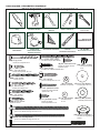 6
6
-
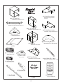 7
7
-
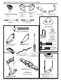 8
8
-
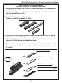 9
9
-
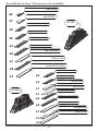 10
10
-
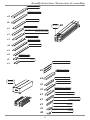 11
11
-
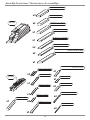 12
12
-
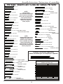 13
13
-
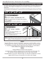 14
14
-
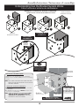 15
15
-
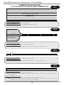 16
16
-
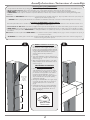 17
17
-
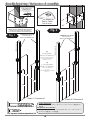 18
18
-
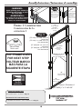 19
19
-
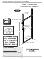 20
20
-
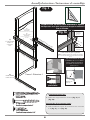 21
21
-
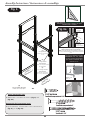 22
22
-
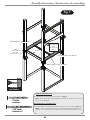 23
23
-
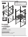 24
24
-
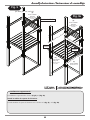 25
25
-
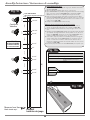 26
26
-
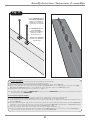 27
27
-
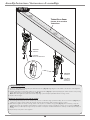 28
28
-
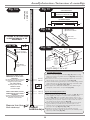 29
29
-
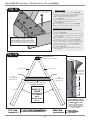 30
30
-
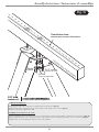 31
31
-
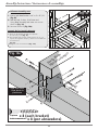 32
32
-
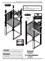 33
33
-
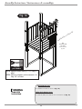 34
34
-
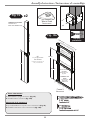 35
35
-
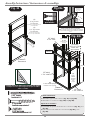 36
36
-
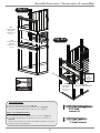 37
37
-
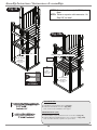 38
38
-
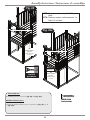 39
39
-
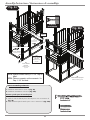 40
40
-
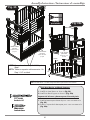 41
41
-
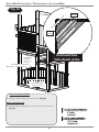 42
42
-
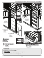 43
43
-
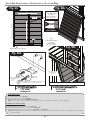 44
44
-
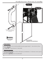 45
45
-
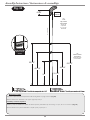 46
46
-
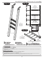 47
47
-
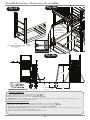 48
48
-
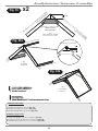 49
49
-
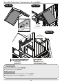 50
50
-
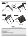 51
51
-
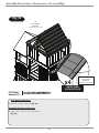 52
52
-
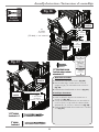 53
53
-
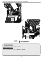 54
54
-
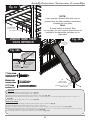 55
55
-
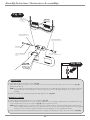 56
56
-
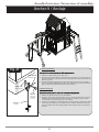 57
57
-
 58
58
-
 59
59
-
 60
60


Swing-N-Slide Playsets PB 9240S Instrucciones de operación
- Tipo
- Instrucciones de operación
- Este manual también es adecuado para
en otros idiomas
Artículos relacionados
-
Swing-N-Slide NE 4610 Manual de usuario
-
Swing-N-Slide Playsets 6039 Instrucciones de operación
-
Swing-N-Slide Playsets WS 5007 Instrucciones de operación
-
-
-
-
-
-
-
Otros documentos
-
Swing-N-Slide WS 4403 Guía de instalación
-
-
-
Yamaha ELS-02C El manual del propietario
-
 Closet Maid Freestanding Bike Rack 3552 Manual de usuario
-
Freedom 73004316 Guía de instalación
-
Allen + Roth TPPER9117 Guía de instalación
-
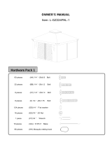 Sunjoy L-GZ224PAL-1 Guía de instalación
-
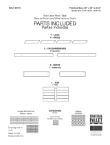 Houseworks, Ltd. 94751 Instrucciones de operación
-
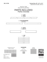 Houseworks, Ltd. 94751 Guía de instalación


