Lutron Electronics Architrave QSWA-KP5-DN Guía de instalación
- Categoría
- Juguetes
- Tipo
- Guía de instalación

Installation Guide
Please Read
SELV / PELV / NEC® Class 2
24–36 V 30 mA
®
QS Wallstations
Contents
Overview ............................................. 2
Power Group Wiring Example.............................. 3
Wiring/Installation ...................................... 4
Mounting............................................. 7
Troubleshooting........................................ 8
Wallstation circuits are classified as SELV / PELV / NEC® Class 2 circuits. As Class
2 circuits, they comply with the requirements of NFPA
® 70, National Electrical
Code
® (NEC®). As SELV / PELV circuits, they comply with the requirements of IEC
60364-4-41, VDE 0100 Part 410, BS7671:1992, and other equivalent standards.
When installing and wiring to these wallstations, follow all applicable national and/
or local wiring regulations. External circuits connected to input, output, and other
communication terminals of wallstations must be supplied from a listed Class 2
source or comply with the requirements for SELV / PELV circuits, as applicable in
your country.
For Programming, see the QS Wallstation Programming
Guide (P/N 0301639) at www.lutron.com/qs
English
Español
Français
Português中文
Deutsch Italiano 日本語

2Installation Instructions Occupant Copy
seeTouch®
Keypads
QSWS2-1B
QSWS2-2B
QSWS2-3B
QSWS2-5B
QSWS2-7B
QSWS2-2BRL
QSWS2-3BRL
QSWS2-5BRL
QSWS2-2BRLIR
QSWS2-3BRLIR
QSWS2-5BRLIR
QSWS2-1RLD
QSWS2-2RLD
QSWS2-3BD
Signature Series
TM
Keypads
QSWAS-1B
QSWAS-2B
QSWAS-3B
QSWAS-5B
QSWAS-7B
QSWAS-2BRL
QSWAS-3BRL
QSWAS-5BRL
QSWAS-1RLD
QSWAS-2RLD
QSWAS-3BD
QS Wallstation Models
seeTouch®
International Keypads
QSWE-2B
QSWE-3B
QSWE-4B
QSWE-5BRL
QSWE-5BRLIR
QSWE-6BRL
QSWE-7BRL
QSWE-8BRL
QSWE-8BRLIR
QSWE-10BRL
Architrave
TM
Keypads
QSWA-KP5-DN
QSWA-KP5-DW
QSWA-KP7-DN
QSWA-KP7-DW
Notes
•
Read all instructions carefully before starting
installation.
• Lutron recommends that wallstations be installed
by a qualified electrician.
• Use only a cloth with warm water and mild soap to
clean faceplates (no chemical cleaners).
Overview
• QS wallstations can be programmed to control
lights, shades, or lights and shades.
• Unprogrammed (out-of-box) QS wallstations,
Sivoia® QS shades, GRAFIK Eye® QS control
units, and Energi Savr NodeTM units will all work
together until they are programmed otherwise.
• Contact closure inputs allow operation with
occupancy/vacancy sensors, partitioning, and
more.
QS Link Limits
• The QS wired communication link is limited to
100 devices and 100 zones. Each QS wallstation
counts as 1 device and 0 zones.
• QS wallstations use 1 power draw unit (PDU) on
the QS link. Refer to the QS Link Power Draw
Units specification submittal (Lutron P/N 369405)
and the diagram on the opposite page for more
information concerning Power Draw Units.
Compatible Components
The following devices are compatible with the QS
link. For more information on each, refer to
www.lutron.com/qs
• GRAFIK Eye
® QS control units
• QS wallstations
• Sivoia® QS shades
• QS Interfaces (contact closure, Ethernet/RS232)
• Quantum® system
• Energi Savr NodeTM units
• QS Sensor Module
• QS Keyswitch

3Occupant Copy Installation Instructions
Power Group Wiring Example
On the QS link, there are devices that supply power and devices that consume power. Each device has a
specific number of Power Draw Units (PDUs) it either supplies or consumes. A Power Group consists of one
device that supplies power and one or more devices that consume power; each Power Group may have
only one power-supplying device. Refer to the QS Link Power Draw Units specification submittal
(Lutron P/N 369405) for more information concerning PDUs.
Within Power Groups on the QS link, connect all 4 terminals (1, 2, 3, and 4), shown by the letter A in the
diagram. Between devices on the QS link that supply power, connect only terminals 1, 3, and 4 (NOT
terminal 2), shown by the letter B on the diagram.
Wiring can be T-tapped or daisy-chained.
LUTRON
LUTRON LUTRON
LUTRON
LUTRON
LUTRON
Connect all 4
terminals within a
power group:
1: Common
2: V+
3 and 4: Data
Connect only 3
terminals between
power groups:
1: Common
3 and 4: Data
Do not connect
Terminal 2: V+
A
A
A
A
B
B
B
B
GRAFIK Eye® QS
control unit
Supplies PDUs
QS Power Supply
Supplies PDUs
Quantum
® Panel
Supplies PDUs
Energi Savr Node
TM
unit
Supplies PDUs
(Do not connect
Terminal 2: V+)
(Do not connect
Terminal 2: V+)
(Do not connect
Terminal 2: V+)
Control Interfaces
Consume PDUs
Wallstations
Consume PDUs
QS Sensor Module with Occupancy
Sensor
Consume PDUs
Power Group 1
Power Group 2
Power Group 3

4Installation Instructions Occupant Copy
Allowable Wiring Configurations
Wiring/Installation
• Refer to the system installation guide and Lutron job
drawings for power cable and data cable (control
link) wiring restrictions and limitations.
• Connect the wallstation to the control link inside the
wallstation’s wallbox or in a junction box (provided
by others).
• Use the wire connector required by local code.
• Control link wiring must not be run in the same
raceway as line voltage.
• The drain/shield wire must be maintained throughout
the control link. Do not connect the shield to earth/
ground or allow contact with the grounded wallbox.
• Do not connect high-voltage power to low-
voltage ter mi nals. Improper wiring can result in
personal injury or damage to the control or to other
equipment.
LUTRON
LUTRON
LUTRON
LUTRONLUTRON
LUTRON
LUTRON
LUTRON
LUTRON
LUTRON
LUTRON LUTRON LUTRON
LUTRON
Daisy chain
LUTRON
LUTRON
LUTRON
LUTRONLUTRON
LUTRON
LUTRON
LUTRON
LUTRON
LUTRON
LUTRON LUTRON LUTRON
LUTRON
T-Tap
Warning! Shock hazard. May result
in serious injury or death. Always turn
OFF the circuit breaker/MCB or remove
the main fuse from the power line before
doing any work.
1. Turn Power OFF. Turn
power OFF at circuit
breaker/MCB (or remove
fuse).
2. Mount Wallbox. Ensure correct size. See
“Mounting” for details.
3. Prepare Wallstations. Remove the faceplate and
set aside.
4. Prepare wires. Strip insulation from wires so that
4 in (10 mm) of bare wire is exposed.
ON
OFF
ON
OFF
ON
OFF
4 in (10 mm)
Wire Sizes (check compatibility in your area)
QS Link Wiring Length Wire Gauge Lutron Cable P/N
Less than 153 m (500 ft) Power (terminals 1 and 2)
1 pair 1.0 mm
2
(18 AWG) GRX-CBL-346S (non-plenum)
GRX-PCBL-346S (plenum)
Data (terminals 3 and 4)
1 twisted, shielded pair 0.5 mm
2
(22 AWG)
153 to 610 m
(500 to 2000 ft)
Power (terminals 1 and 2)
1 pair 4.0 mm
2
(12 AWG) GRX-CBL-46L (non-plenum)
GRX-PCBL-46L (plenum)
Data (terminals 3 and 4)
1 twisted, shielded pair 0.5 mm
2
(22 AWG)
Wire Strip length

5Occupant Copy Installation Instructions
Wiring the QS Link
Connect two 22 AWG (0.5 mm
2
) shielded, twisted
pair wires to terminals 3 and 4 of the wallstation’s
control link connector. Shielding (drain) of the
twisted pair wires must be connected together as
shown, but do not connect the shielding to earth/
ground or the wallstation and do not allow it to
contact the grounded wallbox.
SELV / PELV / NEC® Class 2 control
wiring
(2) 18 AWG (1.0 mm
2
)
1: Common
2: V+
500 to 2000 ft/153 to 610 m
seeTouch®, seeTouch® International
4
3
2
1
Data link: (1) twisted, shielded
pair
22 AWG (0.5 mm
2
)
3: MUX
4: MUX
(2) 12 AWG
(4.0 mm
2
)
(2) 12 AWG
(4.0 mm
2
)
Signature Series
TM, ArchitraveTM
1
2
3
4
Data link: (1) twisted, shielded
pair
22 AWG (0.5 mm
2
)
3: MUX
4: MUX
(2) 12 AWG
(4.0 mm
2
)
(2) 12 AWG
(4.0 mm
2
)
4 3 2 1
C B A
seeTouch® International
SELV / PELV / NEC
®
Class 2 control
wiring
Drain
Data
link
Drain
Drain
1
2
3
4
Drain
Data link
Signature SeriesTM, ArchitraveTM
SELV / PELV / NEC® Class 2
control wiring
4
3
2
1
C
B
A
Drain
Data link
seeTouch®
SELV / PELV / NEC®
Class 2 control
wiring
<500 ft/153 m
Connect the appropriate size wires to terminals 1
and 2 for power, according to your link length (see
table opposite).
SELV / PELV / NEC® Class 2
control wiring
(2) 18 AWG (1.0 mm
2
)
1: Common
2: V+
Data link: (1) twisted, shielded
pair
22 AWG (0.5 mm
2
)
3: MUX
4: MUX
SELV / PELV / NEC® Class 2 control
wiring
(2) 18 AWG (1.0 mm
2
)
1: Common
2: V+
1 2 3 4
MUX
MUX
V+
COM

4 3 2 1
C B A
Installation Instructions Occupant Copy6
Wiring the Contact Closure Input (CCI)
The contact closure inputs must be dry contact
closure, solid state, open collector, or active-low
(NPN)/active-high (PNP) output.
• Open collector NPN or active-low on-state voltage
must be less than 2 V and sink 3.0 mA.
• Open collector PNP or active-high on-state voltage
must be greater than 12 V and source 3.0 mA.
• The outputs must stay in the closed or open states
for at least 60 msec in order to be recognized by
the wallstation.
If there is any question as to whether the third-party
device generating these outputs is compatible with
these specifications, contact the manufacturer.
seeTouch® seeTouch® International
Input 2
Input 2
Common
Common
(3) 18 AWG
(1.0 mm
2
)
(3) 18 AWG
(1.0 mm
2
)
Input 1
Input 1
CO OPERSBURG , PA 18036 USA
:
30 mA
Note: If a wallstation has devices connected
to it through contact closure inputs,
CCI1 “presses” the top button and CCI2
“presses” the bottom button. To change
this behavior, refer to Application Note 428
(seeTouch
® Advanced Programming Mode)
at www.lutron.com.
Exception: On a 2-button wallstation
configured for partitioning, panic, or
sequencing functionality, CCI1 closure
action follows the top button and opening
action follows the bottom button.
ArchitraveTM
(3) 18 AWG
(1.0 mm
2
)
Signature SeriesTM
Input 2
Input 1
(3) 18 AWG
(1.0 mm
2
)
A
B
C
A
B
C
Input 2
Input 1
Common
Common

Occupant Copy Installation Instructions7
Mounting
Carefully mount and align the wallstation as
shown. Screw top and bottom screw into the
control and wallbox. Replace adapter (for insert
versions; screw to control), button assembly, and
faceplate in the order shown.
Power Up
Turn ON control breaker, or replace main fuse.
Installation is Complete
For Programming functions, see the
QS Wallstation Programming Guide at
www.lutron.com/qs.
seeTouch®
Wallbox
Control
Buttons
Adapter
Faceplate
Adapter
screws
Mounting screws
Signature SeriesTM
Wallbox
Control
Buttons
Adapter
Faceplate
Adapter
screws
Mounting
screws
Wallbox
Control
Mounting screws
Adapter
Buttons
Faceplate
Adapter screws
seeTouch® International
Wallbox
Control
Mounting screws
Faceplate
ArchitraveTM
Wallstation Type
Wallbox Size
(high x wide x deep)
Lutron P/N
seeTouch
®
3.75 x 2.25 x 2.75 in
(95 x 55 x 70 mm)
241519
seeTouch
®
International
3 x 3 x 1.5 in
(75 x 75 x 35 mm)
241683
Signature Series
TM
4.5 x 1.5 x 2.75 in
(113 x 39 x 71 mm)
WBOX-SA1-Q1
Architrave
TM
4.5 x 1.25 x 2.75 in
(112 x 32 x 70 mm)
241399

8Installation Instructions Occupant Copy
Troubleshooting: LED Functionality
LED Behavior Meaning and Remedy
All Keypad Types
“Reverse Waterfall”
LEDs light beginning at the bottom, continuing to light
until all are on; then LEDs go off beginning at the bottom,
continuing until all are off. Cycle then repeats.
Unable to communicate on QS link, or alone on QS link. Check link
wiring.
No LED feedback at all, even when a button is pushed. No power to wallstation. Check power wiring.
Another device on QS link is in programming or assignment mode.
Take that device out of programming mode, or put this keypad into
programming mode and then exit programming mode, which turns
off programming mode on all devices.
All LEDs are flashing rapidly. Wallstation is in advanced programming mode. Press and hold the
top and bottom buttons for 3 seconds to exit advanced programming
mode.
Shade Keypads
Top and bottom LEDs are flashing together. Keypad is in assignment mode. Press and hold the top and bottom
buttons for 3 seconds to exit assignment mode.
All LEDs flash 3 times, pause, then repeat. Keypad is in assignment or limit set mode and cannot find or
communicate with any shades assigned to the QS link. Check the
shade wiring.
Wait 60 seconds, and the keypad will automatically return to normal
mode (without any user intervention). Or, press and hold the top and
bottom buttons for 3 seconds to immediately exit the mode.
Top and bottom LEDs light in an alternating pattern (top LED
lights, then goes off, then bottom LED lights, then goes off;
cycle repeats).
Keypad is in limit set mode, or another device on the link is in limit
set mode. Press and hold the top and raise buttons for 3 seconds to
exit limit set mode.
Top and bottom LEDs blink slowly, and one other LED blinks
rapidly.
Keypad is in preset adjust mode. Press and hold the top and bottom
buttons to exit preset adjust mode.
Other Keypads
A single LED is flashing. Keypad is configured for either zone toggle, partitioning, or shade
toggle and is in programming mode. Press and hold the top and
bottom buttons to exit programming mode.
“Forward Waterfall”
LEDs light and go off in sequence from top to bottom.
Keypad is configured for scene, panic, sequence, fine tune, or
scene/zone lockout, and is in programming mode. Press and hold
the top and bottom buttons to exit programming mode.

9Occupant Copy Installation Instructions
Troubleshooting: Shade Functions
Symptom Possible Causes Remedy
EDU (electronic drive unit of the
shade) will not move.
EDU is not powered Check EDU power
Shade fabric is caught on something Check and unbind shade fabric
EDU is not assigned to a keypad Assign the EDU to a keypad
EDU (electronic drive unit of the
shade) does not fully open or
fully close.
Presets have been set incorrectly Try using raise/lower buttons on keypad
Limits have been set incorrectly Set limits correctly
Shade fabric is caught on something Check and unbind shade fabric
Shade moves in the opposite
direction when raise/lower
buttons are pushed.
Open and close limits have been reversed Set limits correctly
Keypad LEDs are off and keypad
will not control any shade.
No power is going to keypad Check and wire power to keypad
Keypad LEDs are on but keypad
will not control any shade.
All presets are set to the same height Try using raise/lower buttons on keypad
Communications link is not wired to the EDU Check and wire the EDU link
EDU has been unassigned from keypad Reassign the EDU to the keypad
Open and close limits are the same Set limits correctly
Keypad does not operate all the
shades it is assigned to.
EDU has been unassigned from keypad Reassign the EDU to the keypad
All presets are set to the same height Try using raise/lower buttons on keypad
EDU is not wired correctly Check and rewire EDU
Keypad is not wired correctly Check and rewire keypad
Shades in a room move on their
own.
EDUs are assigned to a keypad in another
room
Reassign the EDU to the correct keypad

®
Lutron Electronics Co., Inc.
P/N 0301783 Rev. A 6/2015
Internet: www.lutron.com
E-mail: product@lutron.com
WORLD HEADQUARTERS
USA
Lutron Electronics Co., Inc.
7200 Suter Road
Coopersburg, PA
18036-1299
TEL +1.610.282.3800
FAX +1.610.282.1243
Toll-Free 1.888.LUTRON1
Technical Support 1.800.523.9466
North and South America
Technical Hotlines
USA, Canada, Caribbean: 1.800.523.9466
Mexico: +1.888.235.2910
Central/South America: +1.610.282.6701
EUROPEAN HEADQUARTERS
United Kingdom
Lutron EA Ltd.
6 Sovereign Close
London
E1W 3JF United Kingdom
TEL +44.(0)20.7702.0657
FAX +44.(0)20.7480.6899
FREEPHONE (UK) 0800.282.107
Technical support +44.(0)20.7680.4481
ASIAN HEADQUARTERS
Singapore
Lutron GL Ltd.
15 Hoe Chiang Road
#07-03 Euro Asia Centre
Singapore 089316
TEL +65.6220.4666
FAX +65.6220.4333
Asia Technical Hotlines
Northern China: 10.800.712.1536
Southern China: 10.800.120.1536
Hong Kong: 800.901.849
Indonesia: 001.803.011.3994
Japan: +81.3.5575.8411
Macau: 0800.401
Singapore: 800.120.4491
Taiwan: 00.801.137.737
Thailand: 001.800.120.665853
Other countries: +65.6220.4666
Warranty: www.lutron.com/TechnicalDocumentLibrary/Warranty_CommercialSystems.pdf
National Electric Code, NEC, and NFPA are registered trademarks of the National Fire Protection
Association, Inc., Quincy, Massachusetts.
®
Lutron, Lutron, Sivoia, seeTouch, Quantum, and GRAFIK Eye are registered trademarks, and Energi
Savr Node, Signature Series and Architrave are trademarks of Lutron Electron ics Co., Inc.
© 2012–2015 Lutron Electronics Co., Inc.
Troubleshooting
Symptom Possible Causes
No communication with GRAFIK Eye
® control unit or Energi Savr
NodeTM unit.
Miswire or loose connection at the control link data lines 3
and 4.
Wallstation has not been programmed or has been programmed
incorrectly.
Wallstation buttons do not work; LEDs do not track; wallstation
buttons do not function as intended.
Wallstation is miswired.
Wallstation is not powered.
Wallstation is not programmed to the correct device.
Wallstation has not been programmed or has been programmed
incorrectly.
LEDs do not light. Miswire or loose connection at wallstation(s) or processor on the
control link common and power connections 1 and 2.
Wallstation has been programmed incorrectly.
Contact closure inputs or sensor input do not produce the
desired result in the system.
Miswire or loose connection at wallstation sensor/CCI connector.
Wallstation has not been programmed or has been programmed
incorrectly.

Guía de instalación
Lea con atención
SELV / PELV / NEC® Class 2
24–36 V 30 mA
®
Contenido
Descripción general ......................................................................... 2
Ejemplo de cableado del grupo de alimentación ............................... 3
Cableado/Instalación ........................................................................ 4
Montaje ........................................................................................... 7
Resolución de problemas ................................................................. 8
Los circuitos de las botoneras de pared se clasifican como SELV / PELV / NEC®
Class 2. Como circuitos de Class 2, cumplen con los requisitos de NFPA
® 70,
National Electrical Code
® (NEC®). Como circuitos SELV / PELV, cumplen con los
requisitos de IEC 60364-4-41, VDE 0100 Parte 410, BS7671:1992 y otras normas
equivalentes. Al instalar y conectar el cableado a estas botoneras de pared,
siga todas las normas de cableado nacionales y/o locales aplicables. Los circuitos
externos conectados a los terminales de entrada, salida y otros terminales
de comunicación de las botoneras de pared deben provenir de una fuente
listado como Class 2 o cumplir los requisitos de los circuitos SELV / PELV, según
corresponda en su país.
Para la programación, consulte la Guía de programación
de botonera de pared QS (P/N 0301639)
en www.lutron.com/qs
Teclados de pared QS
Español

2Instrucciones de instalación Copia para el ocupante
Botoneras de pared
seeTouch®
QSWS2-1B
QSWS2-2B
QSWS2-3B
QSWS2-5B
QSWS2-7B
QSWS2-2BRL
QSWS2-3BRL
QSWS2-5BRL
QSWS2-2BRLIR
QSWS2-3BRLIR
QSWS2-5BRLIR
QSWS2-1RLD
QSWS2-2RLD
QSWS2-3BD
Botoneras de pared
Signature Series
TM
QSWAS-1B
QSWAS-2B
QSWAS-3B
QSWAS-5B
QSWAS-7B
QSWAS-2BRL
QSWAS-3BRL
QSWAS-5BRL
QSWAS-1RLD
QSWAS-2RLD
QSWAS-3BD
Modelos de botoneras de pared QS
Botoneras de pared
seeTouch® Internacional
QSWE-2B
QSWE-3B
QSWE-4B
QSWE-5BRL
QSWE-5BRLIR
QSWE-6BRL
QSWE-7BRL
QSWE-8BRL
QSWE-8BRLIR
QSWE-10BRL
Botoneras de pared
Architrave
TM
QSWA-KP5-DN
QSWA-KP5-DW
QSWA-KP7-DN
QSWA-KP7-DW
Notas
• Lea detenidamente todas las instrucciones antes
de comenzar con la instalación.
• Lutron recomienda que las botoneras de pared
sean instaladas por un electricista competente.
• Utilice únicamente un paño con agua tibia
y jabón suave para limpiar las placas frontales
(no utilice limpiadores químicos).
Descripción general
• Las botoneras de pared QS se pueden programar
para controlar luces, cortinas, o luces
y cortinas.
• Las botoneras de pared QS, cortinas Sivoia® QS,
unidades de control GRAFIK Eye® y unidades
Energi Savr NodeTM no programadas (como vienen
de fábrica) funcionarán en conjunto, a menos que
se los programe de otra manera.
• Las entradas de contacto seco permitirán
el funcionamiento con sensores de presencia/
vacancia, partición y mucho más.
Límites del enlace QS
• El enlace de comunicación cableado QS
puede tener hasta 100 dispositivos y 100 zonas.
Cada botonera de pared QS cuenta
como 1 dispositivo y 0 zonas.
• Las botoneras de pared QS utilizan 1 unidad
de consumo de energía (PDU) en el enlace QS.
Para obtener más información sobre las unidades
de consumo de energía, consulte el documento
de especificaciones “Unidades de consumo de
energía del enlace QS” (Lutron P/N 369405) y el
diagrama de la página opuesta.
Componentes compatibles
Los siguientes dispositivos son compatibles
con el enlace QS. Para obtener más información
sobre cada dispositivo, visite www.lutron.com/qs
• Unidades de control GRAFIK Eye
® QS
• Botoneras de pared QS
• Cortinas Sivoia® QS
• Interfases QS (contacto seco, Ethernet/RS232)
• Sistema Quantum®
• Unidades Energi Savr NodeTM
• Módulo de sensor QS
• Interruptor QS

3Copia para el ocupante Instrucciones de instalación
Ejemplo de cableado del grupo de alimentación
En el enlace QS, hay dispositivos que proporcionan alimentación y otros que la consumen. Cada dispositivo
tiene un número específico de las unidades de consumo de energía (PDU) que suministra o consume.
Un grupo de alimentación consta de un dispositivo que alimenta y uno o más dispositivos que consumen
energía; cada grupo de alimentación solo puede tener un dispositivo de alimentación. Consulte el documento
de especificaciones “Unidades de consumo de energía en el enlace QS” (Lutron P/N 369405) para obtener
más información sobre las unidades de consumo de energía (PDU).
En los grupos de alimentación del enlace QS, conecte los cuatro terminales (1, 2, 3 y 4) según se muestra
en la letra A del diagrama. Entre los dispositivos del enlace QS que suministran alimentación, conecte solo
los terminales 1, 3 y 4 (NO conecte el terminal 2) según se indica en la letra B del diagrama.
El cableado puede conectarse en cadena o en derivación en T.
LUTRON
LUTRON LUTRON
LUTRON
LUTRON
LUTRON
Conecte los
4 terminales dentro
de un grupo
de alimentación:
1: Común
2: V+
3 y 4: Datos
Conecte solo
3 terminales
entre los grupos
de alimentación:
1: Común
3 y 4: Datos
No conecte
el terminal
2: V+
A
A
A
A
B
B
B
B
Unidad de control
GRAFIK Eye® QS
Suministra PDU
Fuente de
alimentación QS
Suministra PDU
Panel Quantum
®
Suministra PDU
Unidad
Energi Savr Node
TM
Suministra PDU
(No conecte
el terminal 2: V+)
(No conecte
el terminal 2: V+)
(No conecte
el terminal 2: V+)
Interfases de
control
Consume PDU
Botoneras de
pared
Consume PDU
Módulo de sensor QS con sensor de presencia
Consume PDU
Grupo de alimentación 1
Grupo de alimentación 2
Grupo de alimentación 3

4Instrucciones de instalación Copia para el ocupante
Configuraciones de cableado permitidas
Cableado/Instalación
• Consulte la guía de instalación del sistema y los diagramas
de trabajo de Lutron para conocer las restricciones
y limitaciones del cable de alimentación y el cableado
de datos (enlace del control).
•
Conecte la botonera de pared al enlace del control
dentro de la caja de empotrar de la botonera de pared
o en una caja de conexiones (de otro proveedor).
•
Utilice el conector de cable exigido por los códigos locales.
• El cableado del enlace del control no debe correr
en el mismo conducto que la tensión de línea.
•
El cable de descarga/blindaje debe ser continuo a lo largo
del enlace de control. No conecte el blindaje a tierra/masa
ni permita que entre en contacto con la caja de empotrar
conectada a tierra.
•
No conecte la alimentación de alto voltaje a terminales
de bajo voltaje. Un cableado incorrecto puede causar
lesiones personales o daños al control o a otros equipos.
LUTRON
LUTRON
LUTRON
LUTRONLUTRON
LUTRON
LUTRON
LUTRON
LUTRON
LUTRON
LUTRON LUTRON LUTRON
LUTRON
En serie
LUTRON
LUTRON
LUTRON
LUTRONLUTRON
LUTRON
LUTRON
LUTRON
LUTRON
LUTRON
LUTRON LUTRON LUTRON
LUTRON
Derivación
en T
¡Advertencia! Riesgo de descarga
eléctrica. Puede ocasionar lesiones
graves o la muerte. APAGUE siempre
el cortacircuitos/microcortacircuitos o retire
el fusible principal de la línea de alimentación antes
de realizar cualquier trabajo.
1. Desconecte
la alimentación.
Desconecte la alimentación
en el cortacircuitos/
microcortacircuitos
(o retire el fusible).
2. Monte la caja de empotrar. Asegurar el tamaño
correcto. Vea “Montaje” para más detalles.
3. Prepare las botoneras de pared. Retire la placa
frontal y apártela.
4. Prepare los cables. Pele el aislamiento de los
cables de modo que queden expuestos 10mm
(0.375 pulg) del cable.
ON
OFF
ON
OFF
ON
OFF
10 mm (0.375 pulg)
Tamaños de cable (verifique la compatibilidad en su área)
Longitud del cableado
del enlace QS
Calibre del cable Cable Lutron P/N
Menos de 153m
(500pi)
Alimentación (terminales 1 y 2)
1 par de 1,0 mm
2
(18 AWG) GRX-CBL-346S (sin plenum)
GRX-PCBL-346S (con plenum)
Datos (terminales 3 y 4)
1 par trenzado, blindado de 0,5 mm
2
(22 AWG)
153 a 610m
(500 a 2 000pi)
Alimentación (terminales 1 y 2)
1 par de 4,0mm
2
(12 AWG) GRX-CBL-46L (sin plenum)
GRX-PCBL-46L (con plenum)
Datos (terminales 3 y 4)
1 par trenzado, blindado de 0,5 mm
2
(22 AWG)
Longitud de la sección pelada del cable

5Copia para el ocupante Instrucciones de instalación
Cableado del enlace QS
Conecte dos cables de par trenzado y blindado de
0,5mm
2
(22 AWG) a los terminales 3 y 4 del conector
de enlace del control de la botonera de pared. Los
blindajes (la descarga) de los cables de par trenzado
se deben conectar juntos como se muestra en la
ilustración, pero no conecte el blindaje a tierra/masa ni
a la botonera de pared, ni permita que haga contacto
con la caja de empotrar conectada a tierra.
Cableado de control
SELV / PELV / NEC® Class 2
(2) 1,0 mm
2
(18 AWG)
1: Común
2: V+
153 a 610 m/500 a 2 000 pi
seeTouch®, seeTouch® Internacional
4
3
2
1
Enlace de datos: (1) par trenzado y
blindado
0,5 mm
2
(22 AWG)
3: MUX
4: MUX
(2) 4,0 mm
2
(12 AWG)
(2) 4,0 mm
2
(12 AWG)
Signature Series
TM, ArchitraveTM
1
2
3
4
Enlace de datos:
(1) par trenzado y blindado
0,5 mm
2
(22 AWG)
3: MUX
4: MUX
(2) 4,0 mm
2
(12 AWG)
(2) 4,0 mm
2
(12 AWG)
Descarga
Descarga
Cableado de control
SELV / PELV / NEC® Class 2
(2) 1,0 mm
2
(18 AWG)
1: Común
2: V+
4
3
2
1
C
B
A
1
2
3
4
Descarga
Descarga
Cableado de control SELV / PELV / NEC®
Class 2 (2) 1,0 mm
2
(18 AWG)
1: Común
2: V+
Enlace de
datos
Enlace de datos
Enlace de datos: (1) par
trenzado y blindado 0,5 mm
2
(22 AWG)
3: MUX
4: MUX
seeTouch®
Signature SeriesTM, ArchitraveTM
4 3 2 1
C B A
seeTouch® Internacional
Cableado
de control
SELV / PELV / NEC
®
Class 2
Descarga
Enlace de datos
Cableado
de control
SELV / PELV /
NEC
® Class 2
Cableado de control
SELV / PELV / NEC
® Class 2
< 153 m/500 pi
Conecte los cables del tamaño apropiado a las
terminales 1 y 2 para la alimentación, de acuerdo
con la longitud del enlace (consulte la tabla en la
página opuesta).
1 2 3 4
MUX
MUX
V+
COM

4 3 2 1
C B A
Instrucciones de instalación Copia para el ocupante6
Cableado de la entrada de contacto seco (CCI)
Las entradas deben ser de cierre por contacto
seco, de estado sólido, de colector abierto,
o salida de activo bajo (NPN)/activo alto (PNP).
• El voltaje del colector abierto NPN o bajo en activo
en estado encendido debe ser inferior a 2V
y con una capacidad de corriente de sumidero
de 3,0mA.
• El voltaje del colector abierto PNP activo en alto
en estado encendido debe ser mayor a 12V
y fuente de 3,0mA.
• Las salidas tienen que permanecer al menos
60 milisegundos en estado cerrado o abierto
para ser reconocidas por la botonera de pared.
Si hay alguna pregunta sobre si el dispositivo
de un tercero que genera estas salidas
es compatible con estas especificaciones,
comuníquese con el fabricante.
seeTouch® seeTouch® Internacional
Entrada 2
Entrada 2
Común
Común
(3) 1,0 mm
2
(18 AWG)
1,0 mm
2
(18 AWG)
Entrada 1
Entrada 1
CO OPERSBURG , PA 18036 USA
:
30 mA
Nota: Si una botonera de pared tiene dispositivos
conectados a ella a través de entradas
de contacto seco, CCI1 “presiona” el botón
superior y CCI2 “presiona” el botón inferior.
Para cambiar este comportamiento,
consulte la Nota de aplicación 428 (Modo
de programación avanzada de seeTouch® )
en www.lutron.com.
Excepción: En una botonera de pared de
dos botones configurada para las funciones
de partición, pánico o secuenciación,
la acción de cierre CCI1 sigue al botón
superior y la acción de abertura sigue
al botón inferior.
ArchitraveTM
(3) 1,0 mm
2
(18 AWG)
Signature SeriesTM
Entrada 2
Común Común
(3) 1,0 mm
2
(18 AWG)
Entrada 1 Entrada 1
A
B
C
A
B
C
Entrada 2

Copia para el ocupante Instrucciones de instalación7
Montaje
Monte y alinee cuidadosamente la botonera de
pared como se muestra. Ajuste los tornillos superior
e inferior en el control y la caja de empotrar. Vuelva
a colocar el adaptador (para versiones de inserción;
atornille al control) el montaje de botones y la placa
frontal en el orden que se muestra.
Encendido
Conecte el cortacircuitos o vuelva a colocar
el fusible principal.
La instalación está terminada
Para programar las funciones, consulte la Guía
de programación de botonera de pared QS en
www.lutron.com/qs.
Caja de
empotrar
Control
Botones
Adaptador
Placa frontal
Tornillos
del
adaptador
Tornillos de
montaje
Caja de
empotrar
Control
Tornillos de montaje
Adaptador
Botones
Placa frontal
Tornillos del
adaptador
Signature SeriesTM
Caja de
empotrar
Control
Botones
Adaptador
Placa frontal
Tornillos del
adaptador
Caja de
empotrar
Control
Tornillos de montaje
Placa frontal
ArchitraveTM
Tipo de
botonera de
pared
Tamaño de la Caja de
Empotrar
(altura x ancho x
profundidad)
Lutron P/N
seeTouch
®
95 x 55 x 70 mm
(3,75 x 2,25 x 2,75 pulg)
241519
seeTouch
®
Internacional
75 x 75 x 35 mm
(3 x 3 x 1,5 pulg)
241683
Signature
Series
TM
113 x 39.x 71 mm
(4,5 x 1,5 x 2,75 pulg)
WBOX-SA1-Q1
Architrave
TM
112 x 32 x 70 mm
(4,5 x 1,25 x 2,75 pulg)
241399
seeTouch
®
seeTouch® Internacional
Tornillos
de
montaje

8Instrucciones de instalación Copia para el ocupante
Resolución de problemas: Funciones de los indicadores LED
Comportamiento de los indicadores LED Significado y solución
Todos los tipos de botoneras
“Cascada invertida”
Los indicadores LED comienzan a encenderse desde abajo
hasta que todos quedan encendidos; luego se apagan desde
abajo hasta que todos quedan apagados. Luego se repite
el ciclo.
No hay comunicación en el enlace QS o solo en el enlace QS.
Verifique el cableado del enlace.
No hay respuesta de los indicadores LED,
ni siquiera al presionar un botón.
No llega energía a la botonera de pared. Verifique el cableado de la alimentación.
Otro dispositivo en el enlace QS está en el modo de programación o asignación.
Quite ese dispositivo del modo de programación o coloque esta botonera en el
modo de programación y luego salga del modo de programación; esto apagará
el modo de programación en todos los dispositivos.
Todos los indicadores LED parpadean rápidamente. La botonera de pared está en modo de programación avanzada. Mantenga
presionados los botones superior e inferior durante 3 segundos para salir del
modo de programación avanzado
.
Botoneras de cortinas
Los indicadores LED superior e inferior parpadean juntos. La botonera está en el modo de asignación. Mantenga presionados los botones
superior e inferior durante 3 segundos para salir del modo de asignación.
Todos los indicadores LED parpadean 3 veces,
hacen una pausa y luego repiten.
La botonera está en modo de asignación o ajuste de límites y no puede
encontrar ni comunicarse con cortinas asignadas al enlace QS.
Verifique el cableado de las cortinas.
Espere 60 segundos y la botonera volverá al modo normal automáticamente
(sin la intervención del usuario). O bien, mantenga presionados los botones
superior e inferior durante 3 segundos para salir del modo de inmediato.
Los indicadores LED superior e inferior se encienden
de manera alternada (el indicador LED superior se enciende,
luego se apaga, luego se enciende el indicador LED inferior,
luego se apaga; el ciclo se repite).
La botonera está en el modo de ajuste de límites; o bien, otro dispositivo
en elenlace está en el modo de ajuste de límites. Mantenga presionados
los botones superior y aumentar durante 3 segundos para salir del modo
de ajuste de límites.
Los indicadores LED superior e inferior parpadean lentamente,
y otro indicador LED parpadea rápidamente.
La botonera está en el modo de ajuste de niveles predefinidos. Mantenga
presionados los botones superior e inferior para salir del modo de ajuste de
niveles predefinidos.
Otras botoneras
Un solo indicador LED parpadea. La botonera está configurada para conmutación de zona, partición o
conmutación de cortinas y está en el modo de programación. Mantenga
presionados los botones superior e inferior para salir del modo de
programación.
“Cascada frontal”
Los indicadores LED se encienden y se apagan
en una secuencia de arriba hacia abajo.
La botonera está configurada para escena, pánico, secuencia, ajuste fino
o bloqueo de escena/zona, y está en modo de programación. Mantenga
presionados los botones superior e inferior para salir del modo de
programación.

9Copia para el ocupante Instrucciones de instalación
Resolución de problemas: Funciones de las cortinas
Síntomas Posibles causas Solución
La EDU (unidad de drive electrónico
de la cortina) no se mueve.
La EDU no está conectada a la alimentación Verifique la alimentación de la EDU
La tela de la cortina está atrapada en algo Verifique y destrabe la tela de la cortina
La EDU no está asignada a una botonera Asigne la EDU a una botonera
La EDU (unidad de drive electrónico
de la cortina) no se abre ni se cierra
totalmente.
Los niveles predefinidos han sido configurados
de forma incorrecta
Intente usar los botones de aumentar/disminuir
en la botonera
Los límites están configurados de forma incorrecta Configure los límites correctamente
La tela de la cortina está atrapada en algo Verifique y destrabe la tela de la cortina
La cortina se mueve en la dirección
opuesta cuando se presionan los
botones aumentar/disminuir.
Los límites de abierta y cerrada están invertidos Configure los límites correctamente
Los indicadores LED de la botonera
están apagados y la botonera no
controla ninguna cortina.
No llega la alimentación a la botonera Verifique la alimentación del cable a la botonera
Los indicadores LED de la botonera
están encendidos pero la botonera
no controla ninguna cortina.
Todos los niveles predefinidos están configurados
a la misma altura
Intente usar los botones de aumentar/disminuir
en la botonera
El enlace de comunicaciones no está cableado
a la EDU
Verifique y cablee el enlace de la EDU
La EDU ha sido desasignada desde la botonera Reasigne la EDU a la botonera
Los límites de abierta y cerrada son los mismos Configure los límites correctamente
El teclado no opera todas las cortinas
a las que está asignado.
La EDU ha sido desasignada desde la botonera Reasigne la EDU a la botonera
Todos los niveles predefinidos están configurados
a la misma altura
Intente usar los botones de aumentar/disminuir
en la botonera
La EDU no está cableada correctamente Verifique y vuelva a cablear la EDU
La botonera no está cableada correctamente Verifique y vuelva a cablear la botonera
Las cortinas de una habitación
se mueven solas.
Las EDU están asignadas a una botonera
de otra habitación
Reasigne la EDU a la botonera correcta

®
Lutron Electronics Co., Inc.
P/N 0301783 Rev. A 6/2015
Internet: www.lutron.com
Correo electrónico: [email protected]
SEDE CENTRAL MUNDIAL
E.U.A
Lutron Electronics Co., Inc.
7200 Suter Road
Coopersburg, PA
18036-1299
TEL +1.610.282.3800
FAX +1.610.282.1243
Número gratuito 1.888.LUTRON1
Soporte Técnico 1.800.523.9466
América del Norte y América del Sur
Líneas de Asistencia Técnica
E.U.A, Canadá y el Caribe: 1.800.523.9466
México: +1.888.235.2910
América Central/América del Sur: +1.610.282.6701
SEDE CENTRAL EROPEA
Reino Unido
Lutron EA Ltd.
6 Sovereign Close
Londres
E1W 3JF Reino Unido
TEL +44.(0)20.7702.0657
FAX +44.(0)20.7480.6899
LLAMADA GRATUITA (Reino Unido): 0800.282.107
Soporte Técnico: +44.(0)20.7680.4481
SEDE CENTRAL ASIÁTICA
Singapur
Lutron GL Ltd.
15 Hoe Chiang Road
07-03 Euro Asia Centre
Singapur 089316
TEL +65.6220.4666
FAX +65.6220.4333
Líneas de Asistencia Técnica en Asia
Norte de China: 10.800.712.1536
Sur de China: 10.800.120.1536
Hong Kong: 800.901.849
Indonesia: 001.803.011.3994
Japón: +81.3.5575.8411
Macao: 0800.401
Singapur: 800.120.4491
Taiwán: 00.801.137.737
Tailandia: 001.800.120.665853
Otros países: +65.6220.4666
Garantía: www.lutron.com/TechnicalDocumentLibrary/Warranty_CommercialSystems.pdf
National Electric Code, NEC y NFPA son marcas comerciales registradas de la National Fire Protection
Association, Inc., Quincy, Massachusetts.
®
Lutron, Lutron, Sivoia, seeTouch, Quantum, y GRAFIK Eye son marcas registradas y Energi Savr Node,
Architrave, y Signature Series son marcas de Lutron Electronics Co., Inc.
© 2012–2015 Lutron Electronics Co., Inc.
Resolución de problemas
Síntomas Posibles causas
No hay comunicación con la unidad de control GRAFIK Eye®
ni la unidad Energi Savr NodeTM.
Error de cableado o mala conexión en las líneas de datos 3 y 4 del enlace
de control.
No se ha programado la botonera de pared o se programó de manera
incorrecta.
Los botones de la botonera de pared no funcionan, los indicadores
LED no realizan ningún seguimiento; los botones de la botonera
de pared no funcionan de la manera prevista.
La botonera de pared está cableada erróneamente.
La botonera de pared no está conectada a la alimentación.
La botonera de pared no está programada con el dispositivo correcto.
No se ha programado la botonera de pared o se programó de manera
incorrecta.
Los indicadores LED no se encienden. Error de cableado o mala conexión en la(s) botonera(s) o en el procesador
en las conexiones 1 y 2 de la alimentación y el común del enlace de
control.
La botonera de pared se programó de forma incorrecta.
Las entradas de contacto seco o del sensor no producen
los resultados deseados en el sistema.
Error de cableado o mala conexión en el conector de CCI/sensor
de la botonera de pared.
No se ha programado la botonera de pared o se programó de
manera incorrecta.

Installationsanleitung
Bitte lesen
SELV / PELV / NEC® Class 2
24–36 V 30 mA
®
QS Bedienstellen
Inhalt
Übersicht ......................................................................................... 2
Beispiel zur Gruppierung der Stromversorgungen ............................ 3
Anschluss/Installation ...................................................................... 4
Montage .......................................................................................... 7
Fehlersuche ..................................................................................... 8
Die Kreise, in denen sich Bedienstellen befinden, werden als
SELV / PELV
/
NEC® Class 2 eingestuft. Als Kreise der Kategorie 2 genügen
sie den Anforderungen
NFPA® 70, National Electrical Code® (NEC®). Als
Schutzkleinspannungskreise mit Schutzerdung (SELV / PELV) genügen sie
den Anforderungen IEC 60364-4-41, VDE 0100 Teil 410, BS7671:1992 und
anderen gleichwertigen Normen und Standards. Während der Installation und
Verdrahtung der Zusatzgeräte befolgen Sie alle im
jeweiligen Land geltenden und/
oder örtlichen Verdrahtungsvorschriften. Externe Kreise,
die an Eingang, Ausgang
oder andere Schnittstellen der Zusatzgeräte angeschlossen werden, müssen der
Kategorie 2 entsprechen oder allen in Ihrem Land geltenden Anforderungen an
Schutzkleinspannungskreise mit Schutzerdung entsprechen.
Zur Programmierung siehe die Programmieranleitung
für QS Bedienstellen (Bestell-Nr. 0301639)
auf www.lutron.com/qs
Deutsch

2Installationsanweisungen Benutzerexemplar
seeTouch®
Bedienstellen
QSWS2-1B
QSWS2-2B
QSWS2-3B
QSWS2-5B
QSWS2-7B
QSWS2-2BRL
QSWS2-3BRL
QSWS2-5BRL
QSWS2-2BRLIR
QSWS2-3BRLIR
QSWS2-5BRLIR
QSWS2-1RLD
QSWS2-2RLD
QSWS2-3BD
Signature Series
TM
Bedienstellen
QSWAS-1B
QSWAS-2B
QSWAS-3B
QSWAS-5B
QSWAS-7B
QSWAS-2BRL
QSWAS-3BRL
QSWAS-5BRL
QSWAS-1RLD
QSWAS-2RLD
QSWAS-3BD
QS Bedienstellen-Modelle
seeTouch®
Internationale
Bedienstellen
QSWE-2B
QSWE-3B
QSWE-4B
QSWE-5BRL
QSWE-5BRLIR
QSWE-6BRL
QSWE-7BRL
QSWE-8BRL
QSWE-8BRLIR
QSWE-10BRL
Architrave
TM
Bedienstellen
QSWA-KP5-DN
QSWA-KP5-DW
QSWA-KP7-DN
QSWA-KP7-DW
Hinweise
• Lesen Sie alle Anweisungen sorgfältig durch,
bevor Sie mit der Installation beginnen.
• Lutron empfiehlt, dass die Bedienstellen
nur von Fachpersonal installiert werden.
• Nehmen Sie zur Reinigung der Abdeckungen
ausschließlich einen Lappen mit warmem
Wasser und mit Seifenlauge
(keine chemischen Reinigungsmittel).
Übersicht
• QS Bedienstellen können zur Steuerung von
Beleuchtung, Rollos oder von Beleuchtung und
Rollos programmiert werden.
• Unprogrammierte QS Bedienstellen, Sivoia® QS
Rollos, GRAFIK Eye® QS Steuergeräte und
Energi Savr NodeTM Geräte arbeiten alle
zusammen, solange sie nicht anderweitig
programmiert werden.
• Potentialfreie Eingänge ermöglichen Betrieb
mit Präsenzmeldern, Trennwänden u.a.
QS-Bus-Beschränkungen
• Der verdrahtete QS-Kommunikationsbus ist auf
100 Geräte und 100 Zonen begrenzt. Jede QS
Bedienstelle zählt als 1 Gerät und 0 Zonen.
• QS Bedienstellen verbrauchen 1
Stromversorgungseinheit am QS-Bus. Weitere
Informationen zu Stromversorgungseinheiten
finden Sie im Datenblatt zu QS-Bus-
Stromversorgungseinheiten
(Lutron-Bestell-Nr. 369405) und auf der Darstellung
auf der gegenüberliegenden Seite.
Kompatible Komponenten
Die folgenden Geräte sind mit dem QS-Bus
kompatibel. Weitere Informationen finden
Sie auf www.lutron.com/qs
• GRAFIK Eye® QS Steuergeräte
• QS Bedienstellen
• Sivoia® QS Rollos
• QS-Schnittstellen (potentialfreie Kontakte,
Ethernet/RS232)
• Quantum® System
• Energi Savr NodeTM Gerät
• QS-Sensormodul
• QS-Schlüsselschalter

3Benutzerexemplar Installationsanweisungen
Beispiel zur Gruppierung der Stromversorgungen
Am QS-Bus befinden sich Geräte, die Strom liefern, und Geräte, die Strom verbrauchen. Jedes Gerät hat
eine bestimmte Anzahl von Stromeinheiten, die es entweder liefert oder verbraucht. Eine Gruppe besteht
aus einem Gerät, das Strom liefert, und einem oder mehreren Geräten, die Strom verbrauchen. Jede
Leistungsgruppe darf nur ein stromlieferndes Gerät haben. Weitere Informationen zu Stromversorgungseinheiten
finden Sie im Datenblatt zu QS-Bus-Stromversorgungseinheiten (Lutron-Bestell-Nr. 369405).
Verbinden Sie innerhalb der Gruppen am QS-Bus alle 4 Klemmen (1, 2, 3 und 4), die in der Zeichnung mit
dem Buchstaben A gekennzeichnet sind. Verbinden Sie zwischen stromliefernden Geräten am QS-Bus nur
die Klemmen 1, 3 und 4 (NICHT Klemme 2), die in der Zeichnung mit dem Buchstaben B gekennzeichnet sind.
Der Anschluss kann sternförmig oder in Reihe vorgenommen werden.
LUTRON
LUTRON LUTRON
LUTRON
LUTRON
LUTRON
Alle 4 Klemmen
innerhalb einer
Gruppe
anschließen:
1: Masse
2: V+
3 und 4: Daten
Nur 3 Klemmen
zwischen Gruppen
anschließen:
1: Masse
3 und 4: Daten
Klemme 2 nicht
anschließen:
V+
A
A
A
A
B
B
B
B
GRAFIK Eye® QS
Steuergerät
Liefert
Stromver-
sorgungseinheiten
QS-Stromver-
sorgungsgerät
Liefert Stromver-
sorgungseinheiten
Quantum
® Schaltschrank liefert
Stromversorgungseinheiten
Energi Savr Node
TM
Gerät
Liefert Stromversorgungs-
einheiten
(Klemme 2 nicht
anschließen: V+)
(Klemme 2 nicht
anschließen: V+)
(Klemme 2 nicht
anschließen: V+)
Steuer-Schnittstellen
Verbrauchen
Stromversorgungs-
einheiten
Bedienstellen
Verbrauchen
Stromversorgungs-
einheiten
QS-Sensormodul mit Präsenzmelder
Verbrauchen
Stromversorgungseinheiten
Gruppe 1
Gruppe 2
Gruppe 3

4Installationsanweisungen Benutzerexemplar
Mögliche Anschlusskonfigurationen
Anschluss/Installation
• Die Systeminstallationsanleitung und Lutrons
Schaltpläne zur Verkabelung der Starkstrom-
und Datenleitungen (Bus-Leitung) enthalten die
für die Verkabelung geltenden Grenzen und
Beschränkungen.
• Die Bedienstelle muss innerhalb der UP-Dose der
Bedienstelle oder in einer Verteilerdose (bauseits) an
die Busleitung angeschlossen werden.
• Verwenden Sie Klemmen, die gesetzlich
vorgeschrieben sind.
•
Die Busleitungen dürfen nicht zusammen mit
Netzleitungen
verlegt werden.
•
Die Schirmleitung muss entlang der gesamten Busleitung
geführt werden. Verbinden Sie die Schirmleitung nicht
mit Erde/Masse, und achten Sie darauf, dass sie die
geerdete Unterputzdose nicht berührt.
• Schließen Sie Netzspannungsleitungen nie an
Niederspannungsklemmen an. Falsche Verdrahtung
kann zu Verletzungen von Personen führen und
Beschädigungen der Steuerstelle oder anderer
Einrichtungen zur Folge haben.
LUTRON
LUTRON
LUTRON
LUTRONLUTRON
LUTRON
LUTRON
LUTRON
LUTRON
LUTRON
LUTRON LUTRON LUTRON
LUTRON
In Reihe
LUTRON
LUTRON
LUTRON
LUTRONLUTRON
LUTRON
LUTRON
LUTRON
LUTRON
LUTRON
LUTRON LUTRON LUTRON
LUTRON
Abzweig
Achtung! Stromschlaggefahr. Gefahr
schwerer oder tödlicher Verletzungen.
Vor allen Arbeiten muss immer der
Sicherungsautomat ausgeschaltet bzw.
die Hauptsicherung entfernt werden.
1. Schalten Sie den Strom
AUS. Schalten Sie die
Sicherungsautomaten aus
oder entfernen Sie die
Sicherungen.
2. Installation der UP-Dose. Stellen Sie sicher die
richtige Größe. Siehe “Montage” für Einzelheiten.
3. Vorbereitung der Bedienstellen. Nehmen Sie
die Frontplatte ab und legen Sie sie zur Seite.
4. Vorbereitung der Leitungen. Entfernen Sie
von den Drähten 10 mm der Isolierung.
ON
OFF
ON
OFF
ON
OFF
10 mm
Leitungsquerschnitte (überprüfen Sie die Kompatibilität in Ihrer Region)
Länge der QS-Bus-Verdrahtung Drahtquerschnitt Lutron-Kabel Bestell-Nr.
< 153 m Stromversorgung (Klemmen 1 und 2)
1 1,0 mm
2
-Leitungspaar (18 AWG) GRX-CBL-346S (nicht zur Verwendung
in abgehängten Decken)
GRX-PCBL-346S (zur Verwendung
in abgehängten Decken)
Daten (Klemmen 3 und 4)
1 abgeschirmtes verdrilltes 0,5 mm
2
-
Leitungspaar (22 AWG)
153 bis 610 m
Stromversorgung (Klemmen 1 und 2)
1 4,0 mm
2
-Leitungspaar (12 AWG) GRX-CBL-46L (nicht zur Verwendung
in abgehängten Decken)
GRX-PCBL-46L (zur Verwendung
in abgehängten Decken)
Daten (Klemmen 3 und 4)
1 abgeschirmtes verdrilltes 0,5 mm
2
-
Leitungspaar (22 AWG)
Abisolierte
Drahtlänge

5Benutzerexemplar Installationsanweisungen
Verdrahtung des QS-Busses
Schließen Sie zwei abgeschirmte verdrillte 0,5-mm
2
-
Leitungspaare (22 AWG) an die Klemmen 3 und
4 des Busleitungsanschlusses an. Verbinden Sie
die Schirmleitungen der verdrillten Leitungspaare
wie gezeigt miteinander, aber verbinden Sie die
Schirmleitungen nicht mit Erde/Masse oder der
Bedienstelle und lassen Sie sie nicht die geerdete
Unterputzdose berühren.
SELV / PELV/NEC® Class 2-
Steuerleitungen
(2) 1,0 mm
2
(18 AWG)
1: Masse
2: V+
SELV / PELV / NEC
® Class 2-
Steuerleitungen
(2) 1,0 mm
2
(18 AWG)
1: Masse
2: V+
153 bis 610 m
seeTouch®, seeTouch® Internationale
4
3
2
1
Datenverbindung:
(1) abgeschirmtes
verdrilltes
Leitungspaar
0,5 mm
2
(22 AWG)
3: MUX
4: MUX
Signature SeriesTM, ArchitraveTM
1
2
3
4
(2) 4.0 mm
2
(12 AWG)
(2) 4.0 mm
2
(12 AWG)
Abschirmung
Abschirmung
(2) 4,0 mm
2
(12 AWG)
(2) 4,0 mm
2
(12 AWG)
4
3
2
1
C
B
A
1
2
3
4
Abschirmung
Abschirmung
SELV / PELV / NEC
® Class 2-
Steuerleitungen
(2) 1,0 mm
2
(18 AWG)
1: Masse
2: V+
Datenverbindung
Datenverbindung
Datenverbindung: (1)
abgeschirmtes verdrilltes
Leitungspaar
0,5 mm
2
(22 AWG)
3: MUX
4: MUX
seeTouch®
Signature SeriesTM, ArchitraveTM
4 3 2 1
C B A
seeTouch® Internationale
SELV / PELV /
NEC
® Class 2-
Steuerleitungen
Abschirmung
Datenverbindung
SELV / PELV / NEC®
Class
2
-Steuerleitungen
SELV / PELV / NEC
®
Class 2
-Steuerleitungen
<153 m
Datenverbindung:
(1) abgeschirmtes
verdrilltes
Leitungspaar
0,5 mm
2
(22 AWG)
3: MUX
4: MUX
Schließen Sie für die Stromversorgung an Klemme
1 und 2 Leitungen an, die den richtigen Querschnitt
für die Länge der Verbindung haben
(siehe gegenüberliegende Tabelle).
1 2 3 4
MUX
MUX
V+
COM

Installationsanweisungen Benutzerexemplar6
Verdrahtung des potentialfreien Eingangs (CCI)
Die potentialfreien Eingängen können die folgenden
Signale verarbeiten: potentialfreie Kontakte, offener
Kollektor oder active-low (NPN)/active-high (PNP).
• Bei offenem npn-Kollektor oder active-low muss
die Spannung im Durchlasszustand unter 2 V liegen
und 3,0 mA ziehen.
• Bei offenem pnp-Kollektor oder active-high muss
die Spannung im Durchlasszustand über 12 V liegen
und 3,0 mA liefern.
• Die Ausgänge müssen mindestens 60 ms im
geschlossenen oder offenen Zustand bleiben, damit
die Bedienstelle den entsprechenden Zustand erkennt.
Falls Sie Zweifel haben, ob eine Komponente eines
anderen Herstellers mit diesen Spezifikationen
kompatibel ist, wenden Sie sich bitte an den Hersteller.
Hinweis: Falls an einer Bedienstelle Geräte über
potentialfreie Eingänge angeschlossen sind, “bedient”
CCI1 die obere Taste und CCI2 “bedient” die
untere Taste. Um dieses Verhalten zu ändern, siehe
Anwendungshinweis 428 (erweiterter seeTouch
®-
Programmiermodus) auf www.lutron.com.
Ausnahme: An einer 2-Tasten-Bedienstelle, die
für Trennwände, Panik oder Sequenzsteuerung
konfiguriert ist, folgt der Schließvorgang von Eingang
CCI1 auf Druck der oberen Taste
und der Öffnungsvorgang auf Druck
der unteren Taste.
4 3 2 1
C B A
seeTouch® seeTouch® Internationale
Eingang 2
Input 2
Masse
Masse
(3) 1,0 mm
2
(18 AWG)
(3) 1,0 mm
2
(18 AWG)
Eingang 1
Input 1
CO OPERSBURG , PA 18036 USA
:
30 mA
ArchitraveTM
(3) 1,0 mm
2
(18 AWG)
Signature SeriesTM
(3) 1,0 mm
2
(18 AWG)
Eingang 2 Eingang 2
Masse Masse
Eingang 1 Eingang 1
A
B
C
A
B
C

Benutzerexemplar Installationsanweisungen7
Montage
Bringen Sie die Bedienstelle wie abgebildet an
und richten Sie sie sorgfältig aus. Schrauben Sie die
obere und untere Montageschraube in Bedienstelle
und Unterputzdose. Ersetzen Sie denAdapter
(US Ausführungen mit Einsatz – mittels separater
Schrauben), bringen Sie das Tastenkit sowie
die Frontplatte in der gezeigten Reihenfolge an.
Einschalten
Schalten Sie den Sicherungsautomaten ein oder
setzen Sie die Hauptsicherung wieder ein.
Die Installation ist damit abgeschlossen
Zu Programmierfunktionen siehe die Programmieranleitung
für QS Bedienstellen auf www.lutron.com/qs.
seeTouch®
UP-Dose
Steuerstelle
Tastenkit
Adapter
Frontplatte
Montageschrauben
Signature SeriesTM
UP-Dose
Steuerstelle
Tastenkit
Adapter
Frontplatte
Adapter-
schrauben
Montage-
schrauben
UP-Dose
Steuerstelle
Montageschrauben
Adapter
Tastenkit
Frontplatte
Adapterschrauben
seeTouch® Internationale
UP-Dose
Steuerstelle
Montageschrauben
Frontplatte
ArchitraveTM
Bedienstellentyps
UP-Dose größe
(hoch x breit
x tief)
Lutron Bestell-Nr.
seeTouch
® 95 x 55 x 70 mm 241519
seeTouch
®
Internationale
75 x 75 x 35 mm 241683
Signature
TM Series 113 x 39.x 71 mm WBOX-SA1-Q1
Architrave
TM 112 x 32 x 70 mm 241399
Adapterschrauben

8Installationsanweisungen Benutzerexemplar
Fehlersuche: LED-Funktionalität
Verhalten der LEDs Bedeutung und Abhilfe
Alle Bedienstellentypen
Rückwärtslaufend
Die LEDs leuchten nacheinander von unten nach oben auf, bis
alle an sind. Dann gehen sie nacheinander von unten nach oben
aus, bis alle aus sind. Der Vorgang wird dann wiederholt.
Kommunikation am QS-Bus nicht möglich, oder allein am QS-Bus.
Bus-Verdrahtung überprüfen.
Überhaupt keine LED-Rückmeldungen, auch nicht bei
Tastendruck.
Die Bedienstelle erhält keinen Strom. Netzverkabelung überprüfen.
Ein anderes Gerät am QS-Bus ist in Programmier- oder Zuordnungs-
Modus.
Das betreffende Gerät aus dem Programmier-Modus nehmen oder
diese Bedienstelle
in den Programmier-Modus versetzen und dann den
Programmier-Modus verlassen, wodurch der Programmier-Modus an allen
Geräten abgeschaltet wird.
Alle LEDs blinken schnell. Die Bedienstelle befindet sich im erweiterten Programmier-Modus. Zum
Beenden des erweiterten Programmier-Modus die obere und untere Taste
3 Sekunden lang gedrückt halten.
Rollo-Bedienstellen
Obere und untere LED blinken zusammen.
Die Bedienstelle ist im Zuordnungs-Modus. Zum Beenden des Zuordnungs-
Modus die obere und untere Taste 3 Sekunden lang gedrückt halten.
Alle LEDs blinken 3-mal, setzen aus, blinken erneut. Die Bedienstelle befindet sich im Zuordnungs-Modus oder im Modus zum
Einstellen der Endlagen und kann keine Rollos finden, die dem QS-Bus
zugeordnet sind, bzw. mit ihnen kommunizieren. Die Rolloverdrahtung
kontrollieren.
60 Sekunden warten, und die Bedienstelle kehrt automatisch zum normalen
Modus zurück (ohne Benutzereingriff). Oder die obere und untere Taste 3
Sekunden lang gedrückt halten, um den Modus sofort zu verlassen.
Obere und untere LED leuchten abwechselnd auf (obere LED
leuchtet, geht dann aus, untere LED leuchtet, geht dann aus,
dann wird der Vorgang wiederholt).
Die Bedienstelle befindet sich im Modus zum Einstellen der Endlagen
oder ein anderes Gerät amBus befindet sich im Modus zum Einstellen
der Endlagen. Die obere und die Heller-Taste 3 Sekunden lang gedrückt
halten, um den Modus zum Einstellen der Endlagen zu verlassen.
Obere und untere LED blinken langsam, und eine andere LED blinkt
schnell.
Die Bedienstelle befindet sich im Voreinstellungs-Modus. Obere und untere
Taste gedrückt halten, um den Voreinstellungs-Modus zu verlassen.
Andere Bedienstellen
Eine einzige LED blinkt. Die Bedienstelle ist entweder für Zonenumschaltung, Trennwände oder
Rolloumschaltung konfiguriert und befindet sich im Programmier-Modus.
Die obere und untere Taste gedrückt halten, um den Programmier-Modus
zu verlassen.
Vorwärtslaufend
Die LEDs gehen nacheinander von oben nach unten an und aus.
Die Bedienstelle ist für Szene, Panik, Sequenz, Feinabstimmung
oder Szenen/Zonen-Verriegelung konfiguriert und befindet sich im
Programmier-Modus. Die obere und untere Taste gedrückt halten, um den
Programmier-Modus zu verlassen.

9Benutzerexemplar Installationsanweisungen
Fehlersuche: Rollofunktionen
Anzeichen Mögliche Ursachen Abhilfe
Die EDU (elektronische
Antriebseinheit des Rollos) bewegt
sich nicht.
Die EDU wird nicht mit Strom versorgt Die Stromversorgung der EDU kontrollieren
Der Stoff des Rollos hängt irgendwo fest Den Stoff überprüfen und ggf. lösen
Die EDU ist keiner Bedienstelle zugeordnet Die EDU einer Bedienstelle zuordnen
Die EDU (elektronische
Antriebseinheit des Rollos) öffnet
oder schließt nicht vollständig.
Die Voreinstellungen sind falsch eingestellt Die Heller/Dunkler-Tasten an der Bedienstelle
ausprobieren
Die Endlagen wurden falsch eingestellt Die Endlagen richtig einstellen
Der Stoff des Rollos hängt irgendwo fest Den Stoff überprüfen und ggf. lösen
Das Rollo bewegt sich in die
entgegengesetzte Richtung,
wenn die Heller/Dunkler-Tasten
gedrückt werden.
Die Endlagen beim Öffnen und Schließen wurden
vertauscht
Die Endlagen richtig einstellen
Die LEDs der Bedienstelle sind aus
und die Bedienstelle kann kein Rollo
steuern.
Die Bedienstelle erhält keinen Strom Die Stromversorgung zur Bedienstelle
kontrollieren und herstellen
Die LEDs der Bedienstelle leuchten,
aber die Bedienstelle kann kein Rollo
steuern.
Alle Voreinstellungen befinden sich in der gleichen
Höhe
Die Heller/Dunkler-Tasten an der Bedienstelle
ausprobieren
Der Kommunikationslink ist nicht an der EDU
angeschlossen
Den EDU-Link kontrollieren und herstellen
Die Zuordnung der EDU zur Bedienstelle wurde
aufgehoben
Die EDU der Bedienstelle neu zuordnen
Die Endlagen beim Öffnen und Schließen sind
gleich
Die Endlagen richtig einstellen
Die Bedienstelle steuert nicht alle
zugeordneten Rollos.
Die Zuordnung der EDU zur Bedienstelle wurde
aufgehoben
Die EDU der Bedienstelle neu zuordnen
Alle Voreinstellungen befinden sich in der gleichen
Höhe
Die Heller/Dunkler-Tasten an der Bedienstelle
ausprobieren
Die EDU ist nicht richtig verkabelt Die EDU kontrollieren und neu verdrahten
Die Bedienstelle ist nicht richtig verkabelt Die Bedienstelle kontrollieren und neu verdrahten
Die Rollos in einem Raum bewegen
sich von selbst.
Die EDUs wurden einer Bedienstelle in einem
anderen Raum zugeordnet
Die EDU der richtigen Bedienstelle zuordnen

®
Lutron Electronics Co., Inc.
Bestell-Nr. 0301783 Rev. A 6/2015
Internet: www.lutron.com
E-Mail: [email protected]
WELTWEITE ZENTRALE
USA
Lutron Electronics Co., Inc.
7200 Suter Road
Coopersburg, PA
18036-1299
TEL. +1.610.282.3800
FAX +1.610.282.1243
Gebührenfrei 1.888.LUTRON1
Technische Unterstützung 1.800.523.9466
Nord- und Südamerika
Technische Hotlines
USA, Kanada, Karibik: 1.800.523.9466
Mexiko: +1.888.235.2910
Mittel-/Südamerika: +1.610.282.6701
EUROPA-ZENTRALE
Großbritannien
Lutron EA Ltd.
6 Sovereign Close
London
E1W 3JF United Kingdom
TEL. +44.(0)20.7702.0657
FAX +44.(0)20.7480.6899
GEBÜHRENFREI (Deutschland) 0800.1815.134
Technische Unterstützung +44.(0)20.7680.4481
ASIEN-ZENTRALE
Singapur
Lutron GL Ltd.
15 Hoe Chiang Road
#07-03 Euro Asia Centre
Singapur 089316
TEL. +65.6220.4666
FAX +65.6220.4333
Asien, technische Hotlines
Nord-China: 10.800.712.1536
Süd-China: 10.800.120.1536
Hongkong: 800.901.849
Indonesien: 001.803.011.3994
Japan: +81.3.5575.8411
Macau: 0800.401
Singapur: 800.120.4491
Taiwan: 00.801.137.737
Thailand: 001.800.120.665853
Andere Länder: +65.6220.4666
Garantie: www.lutron.com/TechnicalDocumentLibrary/Warranty_CommercialSystems.pdf
National Electric Code, NEC und NFPA sind eingetragene Warenzeichen der National Fire Protection
Association, Inc., Quincy, Massachusetts.
®
Lutron, Lutron, Sivoia, seeTouch, Quantum und GRAFIK Eye sind eingetragene Warenzeichen und Energi
Savr Node, Architrave und Signature Series sind Warenzeichen von Lutron Electronics Co., Inc.
© 2012–2015 Lutron Electronics Co., Inc.
Fehlersuche
Anzeichen Mögliche Ursachen
Keine Kommunikation mit dem GRAFIK Eye
®-Steuergerät oder dem
Energi Savr Node
TM-Gerät.
Fehlerhafte Verdrahtung oder lose Verbindung der Datenleitungen
3 und 4 der Busleitung.
Die Bedienstelle wurde nicht programmiert oder falsch programmiert.
Bedienstellentasten funktionieren nicht; LEDs reagieren nicht;
Bedienstellentasten funktionieren nicht wie vorgesehen.
Die Bedienstelle ist falsch angeschlossen.
Die Bedienstelle wird nicht mit Strom versorgt.
Die Bedienstelle ist nicht für die richtige Komponente programmiert.
Die Bedienstelle wurde nicht programmiert oder falsch programmiert.
Die LEDs leuchten nicht. Fehlerhafte Verdrahtung oder lose Verbindung an den Bedienstellen
oder
am Prozessor in der Netz- oder Masseleitung der Busleitung (1 und
2).
Die Bedienstelle wurde falsch programmiert.
Eingänge mit potentialfreien Kontakten oder Sensoreneingänge führen
nicht zum gewünschten Ergebnis im System.
Fehlerhafte Verdrahtung oder lose Verbindung am Sensoren-/CCI-
Anschluss der Bedienstelle.
Die Bedienstelle wurde nicht programmiert oder falsch programmiert.

Guide d’installation
Veuillez lire attentivement
SELV / PELV / NEC® Class 2
24–36 V 30 mA
®
Stations murales QS
Contenu
Exposé général ................................................................................ 2
Exemple de câblage de groupe de puissance .................................. 3
Câblage/Installation ......................................................................... 4
Montage .......................................................................................... 7
Dépistage de défauts ....................................................................... 8
Les circuits de station murale sont classifiés SELV / PELV / NEC® circuits Class 2.
Les circuits Class 2 sont conformes aux règlements du NFPA
® 70, National Electrical
Code
® (NEC®). Les circuits SELV / PELV sont conformes aux règlements du IEC 60364-4-
41, VDE 0100 Partie 410, BS7671:1992 et à d’autres standards équivalents. Lors
de l’installation et du câblage de ces stations murales, vous devez suivre tous les
règlements de câblage des codes nationaux et/ou locaux applicables. Les circuits
externes connectés aux entrées, aux sorties et autres terminaux de communication de
stations murales, doivent être fournis à partir de la source listée Class 2 ou être conforme
aux conditions pour les circuits SELV / PELV tel qu’appliqué dans notre pays.
Pour la programmation, consulter le guide de programmation
de station murale QS (P/N 0301639) au www.lutron.com/qs
Français

2Directives d’installation Copie de l’occupant
Claviers
seeTouch
®
QSWS2-1B
QSWS2-2B
QSWS2-3B
QSWS2-5B
QSWS2-7B
QSWS2-2BRL
QSWS2-3BRL
QSWS2-5BRL
QSWS2-2BRLIR
QSWS2-3BRLIR
QSWS2-5BRLIR
QSWS2-1RLD
QSWS2-2RLD
QSWS2-3BD
Claviers
Signature Series
TM
QSWAS-1B
QSWAS-2B
QSWAS-3B
QSWAS-5B
QSWAS-7B
QSWAS-2BRL
QSWAS-3BRL
QSWAS-5BRL
QSWAS-1RLD
QSWAS-2RLD
QSWAS-3BD
Modèles de stations murales QS
Claviers seeTouch®
Internationale
QSWE-2B
QSWE-3B
QSWE-4B
QSWE-5BRL
QSWE-5BRLIR
QSWE-6BRL
QSWE-7BRL
QSWE-8BRL
QSWE-8BRLIR
QSWE-10BRL
Claviers
Architrave
TM
QSWA-KP5-DN
QSWA-KP5-DW
QSWA-KP7-DN
QSWA-KP7-DW
Remarques
•
Veuillez lire attentivement toutes les directives
avant de procéder à l’installation.
• Lutron recommande que les stations murales
soient installées par un électricien qualifié.
• Pour nettoyer les faces avants, utiliser uniquement
un linge avec de l’eau tiède et un savon doux
(aucun nettoyant chimique).
Exposé général
• Les stations murales QS peuvent être
programmées pour contrôler l’éclairage, les stores
ou l’éclairage et les stores.
• Les stations murales (hors de la boîte) QS non
programmées, les stores Sivoia
® QS, les unités
de contrôle GRAFIK Eye
® QS, les unités Energi
Savr Node
TM fonctionnent tous ensemble sauf si
programmés autrement.
• Les entrées à contact sec permettent
le fonctionnement des détecteurs de présence
et d’absence, de cloisonnement et plus encore.
Limites de la liaison QS
• La liaison de communication câblée QS est limitée
à 100 dispositifs et à 100 zones. Chaque station
murale seeTouch
® compte comme 1 dispositif
et 0 zone.
• Les stations murales QS utilisent 1 unité de
puissance absorbée (PDU) sur la liaison QS.
Pour plus d’information concernant les unités de
puissance absorbée, se référer aux spécifications
soumises pour les unités de puissance absorbée
de liaison QS (Lutron P/N 369405) et au schéma à
la page opposée.
Composantes compatibles
Les dispositifs suivants sont compatibles avec
la liaison QS. Pour plus d’information sur chacun,
se référer au www.lutron.com/qs
• Unités de contrôle GRAFIK Eye
® QS
• Stations murales QS
• Stores Sivoia
® QS
• Interfaces QS (contact sec, Ethernet/RS232)
• Système Quantum
®
• Unités Energi Savr NodeTM
• Module de détection QS
• Interrupteur à clé QS

3Copie de l’occupant Directives d’installation
Exemple de câblage de groupe de puissance
Sur la liaison QS, il y a des dispositifs qui consomment de l’énergie et des dispositifs qui en fournissent.
Chaque dispositif possède un nombre spécifique d’unités de puissance absorbée (PDU). Il fourni ou
consomme. Un groupe de puissance comprend un dispositif d’alimentation et un ou plusieurs dispositifs
de consommation; chaque groupe de puissance peut avoir qu’un seul dispositif d’alimentation. Se référer
aux spécifications soumises des unités de puissance absorbée de liaison QS (Lutron P/N 369405) pour plus
d’information concernant les PDU.
Pour chaque groupe de puissance de liaison QS, connecter les 4 bornes de raccordement (bornes 1, 2,
3 et 4) identifiées par la lettre A sur le schéma. Pour les dispositifs qui servent d’alimentation de liaison QS,
ne raccorder que les bornes 1, 3 et 4 (ne PAS raccorder la borne 2) module indiqué par la lettre B
sur le schéma.
Le câblage peut être sous forme de branchement en T ou en cascade.
LUTRON
LUTRON LUTRON
LUTRON
LUTRON
LUTRON
Connecter les
4 bornes de
raccordement
à l’intérieur
d’un groupe
de puissance :
1: Commun
2 : V+
3 et 4 : Données
Connecter
seulement
3 bornes de
raccordement
entre les groupes
de puissance :
1: Commun
3 et 4 : Données
Ne pas faire de
connexion à la
borne2: V+
A
A
A
A
B
B
B
B
GRAFIK Eye® QS
unité de contrôle
Fournitures
des PDU
Bloc d’alimentation QS
Fournitures des PDU
Panneau Quantum
®
Fournitures des PDU
Appareil
Energi Savr Node
TM
Fournitures des PDU
(Ne pas faire de connexion
à la borne2: V+))
(Ne pas faire de connexion
à la borne2: V+)
(Ne pas faire de connexion
à la borne2: V+)
Interfaces de contrôle
PDU consommés
Stations murales
PDU consommés
Module détecteur QS avec détecteur
de présence
PDU consommés
Groupe de puissance 1
Groupe de puissance 2
Groupe de puissance 3

4Directives d’installation Copie de l’occupant
Configurations de câblage admissibles
Câblage/Installation
• Pour connaître les limites et restrictions d’installation
des câbles d’alimentation et de données (barre de
communication), se référer au guide d’installation
du système et aux schémas de travail de Lutron.
•
Connecter la station murale à la barre de communication
à l’intérieur de la boîte murale de la station murale
ou dans une boîte de jonction (fournie par des tiers).
•
Utiliser un capuchon de connexion tel que requis
par le code local.
• Le câblage de la barre de communication ne doit pas
être tiré dans la même canalisation que celle du câble
d’alimentation secteur.
•
Le fil de blindage ou de drain doit être continu sur toute
la longueur de la barre de communication. Ne pas
connecter le blindage à la mise à la terre ou permettre
tout contact avec un boîtier mis à la terre.
•
Ne pas connecter l’alimentation haute tension à des bornes
de raccordement de basse tension. Un câblage inadéquat
peut résulter à des blessures corporelles ou des dommages
au contrôle ou à d’autres équipements.
LUTRON
LUTRON
LUTRON
LUTRONLUTRON
LUTRON
LUTRON
LUTRON
LUTRON
LUTRON
LUTRON LUTRON LUTRON
LUTRON
Guirlande
LUTRON
LUTRON
LUTRON
LUTRONLUTRON
LUTRON
LUTRON
LUTRON
LUTRON
LUTRON
LUTRON LUTRON LUTRON
LUTRON
Prise en T
Avertissement! Choc électrique
pouvant causer des blessures
graves, voire la mort. Toujours mettre
le disjoncteur/MCB (disjoncteur principal)
hors circuit ou enlever le fusible principal
de la ligne secteur avant d’effecteur tout travail.
1. Couper l’alimentation
OFF. Couper le courant
au disjoncteur principal/
MCB (ou enlever le fusible).
2. Monter la boîte murale.
Assurez-vous que la dimension soit exacte. Voir
“Montage” pour les détails.
3. Préparer les stations murales. Retirer la plaque
murale et mettre de côté.
4. Préparer les fils. Dénuder l’isolation des fils de
sorte que 10 mm (0.375 po) de fil nu soit exposé.
ON
OFF
ON
OFF
ON
OFF
10 mm (0,375 po)
Grosseur de fil (vérifier la compatibilité dans votre région)
Longueur de câble de
liaison QS
Calibre des fils Câble Lutron P/N
Moins de 153 m (500 pi) Puissance (bornes 1 et 2)
1 paire 1,0 mm
2
(18 AWG) Câble GRX-CBL-346S (non-plenum)
Câble GRX-PCBL-346S (plenum)
Données (bornes 3 et 4)
1 paire torsadée et blindée 0,5 mm
2
(22 AWG)
153 à 610 m
(500 à 2 000 pi)
Puissance (bornes 1 et 2)
1 paire 4,0 mm
2
(12 AWG) GRX-CBL-46L (non-plenum)
GRX-PCBL-46L (plenum)
Données (bornes 3 et 4)
1 paire torsadée et blindée 0,5 mm
2
(22 AWG)
Longueur de dénudage

5Copie de l’occupant Directives d’installation
Câblage de la liaison QS
Connecter deux paires de fils torsadés blindés de
0,5 mm
2
(22 AWG) aux bornes 3 et 4 du connecteur
de la barre de communication de la station murale.
Le blindage (drain) des câbles de paire torsadée doit
être connecté ensemble tel que démontré mais ne
pas connecter le blindage à la mise à la terre ou la
station murale et ne permettez pas de contact avec
la mise à la terre de la boîte murale.
Câblage de contrôle
SELV / PELV / NEC® Class 2, (2) 1,0
mm
2
(18 AWG)
1: Commun
2 : V+
Câblage de contrôle SELV / PELV / NEC®
Class 2, (2) 1,0 mm
2
(18 AWG)
1: Commun
2 : V+
153 à 610 m/500 à 2 000 pi
seeTouch®, seeTouch® Internationale
4
3
2
1
Liaison de données: (1) paire
torsadée, blindée 0,5 mm
2
(22 AWG)
3 : MUX
4 : MUX
(2) 4,0 mm
2
(12 AWG)
(2) 4,0 mm
2
(12 AWG)
Signature Series
TM, ArchitraveTM
1
2
3
4
Liaison de données: (1) paire
torsadée, blindée 0,5 mm
2
(22 AWG)
3 : MUX
4 : MUX
(2) 4,0 mm
2
(12 AWG)
(2) 4,0 mm
2
(12 AWG)
Drain
Drain
4
3
2
1
C
B
A
1
2
3
4
Drain
Drain
Câblage de contrôle
SELV / PELV /
NEC® Class 2
(2) 1,0 mm
2
(18 AWG)
1: Commun
2 : V+
Liaison de
données
Liaison de
données
Liaison de données: (1) paire
torsadée, blindée
0,5 mm
2
(22 AWG)
3 : MUX
4 : MUX
seeTouch®
Signature SeriesTM, ArchitraveTM
4 3 2 1
C B A
seeTouch® Internationale
Câblage de contrôle
SELV / PELV /
NEC®
Class 2
Liaison de
données
Câblage
de contrôle
SELV / PELV /
NEC®
Class 2
Câblage de contrôle
SELV / PELV /
NEC® Class 2
<153 m/500 pi
Drain
Connecter la grosseur de fil approprié aux bornes
1 et 2 pour l’alimentation, selon votre longueur de
liaison (voir tableau ci-contre).
1 2 3 4
MUX
MUX
V+
COM

4 3 2 1
C B A
Directives d’installation Copie de l’occupant6
Câblage d’entrée à contacts secs (CCI)
Les entrées à contacts secs doivent être à contacts
secs, semi-conducteur, collecteur ouvert, ou sortie
active à l’ état bas (NPN)/ à l’ état haut (PNP).
• La tension d’entrée du collecteur ouvert NPN ou
de l’entrée active à l’ état bas doit être inférieure
à 2 V et baisser de 3,0 mA.
• La tension d’entrée du collecteur ouvert PNP
ou de l’entrée active à l’état haut doit être supérieur
à 12 V et doit générer 3,0 mA.
• Les sorties doivent demeurer à l’état fermé
ou ouvert pendant au moins 60 msec afin d’être
reconnues par la station murale.
S’il y a des questions à savoir si le dispositif
d’un tiers qui génère ces sorties est compatible
avec les spécifications, communiquer avec
le fabricant.
seeTouch®
seeTouch® Internationale
Entrée 2
Entrée 2
Commun
Commun
(3) 1,0 mm
2
(18 AWG)
(3) 1,0 mm
2
(18 AWG)
Entrée 1
Entrée 1
CO OPERSBURG , PA 18036 USA
:
30 mA
Remarque : Si une station murale a des
dispositifs qui lui sont reliés via des
entrées à contacts secs, CCI1
“appuie” sur le bouton du haut et
CCI2 “appuie” sur le bouton du bas.
Pour changer ce comportement, se
référer à la Note d’Application 428
(seeTouch® Mode de Programmation
Advanced) au www.lutron.com.
Exception : Pour une station murale
à 2 boutons configurée pour les
fonctionnalités de cloisonnement,
panique ou de séquencement,
l’action de fermeture CCI1 suit
le bouton du haut et l’action
d’ouverture suit le bouton du bas.
ArchitraveTM
(3) 1,0 mm
2
(18 AWG)
Signature SeriesTM
Entrée 2 Entrée 2
Commun
(3) 1,0 mm
2
(18 AWG)
Entrée 1 Entrée 1
A
B
C
A
B
C
Commun

Copie de l’occupant Directives d’installation7
seeTouch® Internationale
Montage
Monter soigneusement et aligner la station murale
tel que démontrée. Vissez la vis du haut et du bas
dans le contrôle de la boîte murale. Remplacer
l’adaptateur (pour versions ancrage; visser
au contrôle), assemblage de bouton et la face
avant dans l’ordre démontré.
Mettre sous tension
Activer le disjoncteur de contrôle, ou remettre
le fusible principal en place.
Installation est complétée
Pour les fonctions de programmation, se référer
au Guide de programmation de station murale QS
à www.lutron.com/qs
Boîte murale
Contrôle
Boutons
Adaptateur
Face avant
Vis adaptatrices
Vis de montage
Boîte
murale
Contrôle
Vis de montage
Adaptateur
Boutons
Face avant
Vis adaptatrices
seeTouch®
Signature SeriesTM
Boîte murale
Contrôle
Boutons
Adaptateur
Face avant
Vis
adaptatrices
Vis de
montage
Boîte
murale
Contrôle
Vis de montage
Face avant
ArchitraveTM
Type de
poste mural
Dimension de
boîte murale
(haut x large x profond)
Lutron P/N
seeTouch
®
95 x 55 x 70 mm
(3,75 x 2,25 x 2,75 po)
241519
seeTouch
®
Internationale
75 x 75 x 35 mm
(3 x 3 x 1,5 po)
241683
Signature Series
TM
113 x 39.x 71 mm
(4,5 x 1,5 x 2,75 po)
WBOX-SA1-Q1
Architrave
TM
112 x 32 x 70 mm
(4,5 x 1,25 x 2,75 po)
241399

8Directives d’installation Copie de l’occupant
Dépistage de défauts : Fonctionnalité DEL
Comportement de la DEL Problème et solution
Tout type de clavier
“Séquencement inversé”
Les DEL s’illuminent à partir du bas, en continuation jusqu’à
ce qu’elles soient toutes allumées; ensuite les DEL s’éteignent
en commençant par le bas, en continuation jusqu’à ce qu’elles
soient toutes éteintes. Ensuite, le cycle se répète.
Incapable de communiquer avec la liaison QS, ou seul sur la liaison QS.
Vérifier le câble de liaison.
Aucune rétroaction DEL du tout, même en appuyant sur le bouton. Aucune puissance à la station murale. Vérifier le câblage de puissance.
Un autre dispositif sur la liaison QS est en mode de programmation
ou d’assignation. Sortir ce dispositif du mode de programmation,
ou mettre ce clavier en mode de programmation et ensuite sortir
du mode de programmation, ce qui fera sortir du mode de programmation
tous les dispositifs.
Toutes les DEL clignotent rapidement. La station murale est en mode de programmation advanced. Appuyer
et maintenir enfoncés les boutons haut et bas pendant 3 secondes afin de
sortir du mode de programmation advanced.
Claviers de store
Les DEL du haut et du bas clignotent ensemble. Le clavier est en mode d’assignation. Pour sortir du mode d’assignation,
appuyer et maintenir enfoncés les boutons haut et bas pendant 3 secondes.
Toutes les DEL clignotent 3 fois, pausent, ensuite le cycle se
répète.
Le clavier est réglé en mode d’assignation ou de limite et ne peut trouver ou
communiquer avec aucun store assigné à la liaison QS. Vérifier le câblage
du store.
Attendre 60 secondes, et le clavier retournera automatiquement en mode
normal (sans l’intervention de l’utilisateur). Ou, appuyer et maintenir
enfoncés les boutons haut et bas pendant 3 secondes pour sortir
immédiatement de ce mode.
Les DEL du haut et du bas éclairent en alternance (DEL du haut
s’allume, ensuite s’éteint, ensuite la DEL du bas s’allume, ensuite
s’éteint; le cycle se répète).
Le clavier est réglé en mode limite, ou un autre dispositif sur la liaison est
réglé en mode limite. Appuyer et maintenir enfoncés le bouton du haut et
le bouton hausser pendant 3 secondes afin de sortir du mode de réglage
limite.
Les DEL haut et bas clignotent lentement, et une autre DEL
clignote rapidement.
Le clavier est en mode ajustement de préréglage. Appuyer et maintenir
enfoncés les boutons haut et bas pour sortir du mode ajustement de
préréglage.
Autres claviers
Une seule DEL clignote. Le clavier est configuré en mode de bascule pour zone, cloisonnement
ou bascule pour store et est en mode de programmation. Appuyer
et maintenir enfoncés les boutons haut et bas pour sortir du mode
de programmation.
“Escalade séquentielle”
Les DEL s’allument et s’éteignent en escalade de séquence
de haut en bas.
Le clavier est configuré pour scène, panique, séquence, précision,
ou verrouillage de scène/zone, et est en mode de programmation.
Appuyer et maintenir enfoncés les boutons haut et bas pour sortir
du mode de programmation.

9Copie de l’occupant Directives d’installation
Dépistage de défauts : Fonctions stores
Symptôme Causes possibles Solution
L’unité EDU (unité de conduite
électronique du store) ne bouge pas.
L’unité EDU n’est pas alimentée Vérifier l’alimentation de l’unité EDU
Le tissu du store est retenu par quelque chose Vérifier et dégager le tissu du store
L’unité EDU n’est pas assignée à un clavier Assigner l’unité EDU à un clavier
L’unité EDU (unité de conduite
électronique du store) ne peut
ni s’ouvrir, ni se fermer
complètement.
Les préréglages ont été réglés incorrectement Essayer d’utiliser les boutons hausser/baisser
sur le clavier
Les limites ont été réglées incorrectement Régler les limites correctement
Le tissu du store est retenu par quelque chose Vérifier et dégager le tissu du store
Le store se déplace dans la direction
opposée lorsque les boutons
hausser/baisser sont appuyés.
Les limites d’ouverture et de fermeture ont été
inversées
Régler les limites correctement
Les DEL du clavier sont éteintes off
et le clavier ne contrôle aucun store.
Aucune puissance ne se rend au clavier Vérifier et effectuer le câblage d’alimentation
au clavier
Les DEL du clavier sont allumées
(on) mais le clavier ne contrôle
aucun store.
Tous les préréglages sont réglés à la même
hauteur
Essayer d’utiliser les boutons hausser/baisser
sur le clavier
La liaison des communications n’est pas câblée
à l’unité EDU
Vérifier et effectuer le câblage de la liaison
de l’unité EDU
L’unité EDU a été non assignée au clavier Réaffectation de l’unité EDU au clavier
Les limites ouvert et fermé sont identiques Régler les limites correctement
Le clavier ne contrôle pas tous
les stores qui lui sont assignés.
L’unité EDU a été non assignée au clavier Réaffectation de l’unité EDU au clavier
Tous les préréglages sont réglés à la même
hauteur
Essayer d’utiliser les boutons hausser/baisser
sur le clavier
L’unité EDU n’est pas câblée correctement Vérifier et refaire le câblage de l’unité EDU
Le câblage au clavier est incorrect Vérifier et refaire le câblage du clavier
Les stores dans la pièce se
déplacent par eux-mêmes.
Les unités EDU sont assignées à un clavier
d’une autre pièce
Réaffecter l’unité EDU au bon clavier

®
Lutron Electronics Co., Inc.
P/N 0301783 Rev. A 6/2015
Site Internet: www.lutron.com
Courriel: [email protected]
SIÈGE SOCIAL MONDIAL
États-Unis
Lutron Electronics Co., Inc.
7200 Suter Road
Coopersburg, PA
18036-1299
TÉL +1.610.282.3800
TÉLÉC. : +1.610.282.1243
Sans frais 1-888-LUTRON1
Assistance technique 1.800.523.9466
Amérique du nord et du sud
Lignes de support technique
États-Unis, Canada, Caraïbe: 1.800.523.9466
Mexique : +1.888.235.2910
Amérique Centrale/du Sud : +1.610.282.6701
SIÈGE EUROPÉEN
Royaume-Uni
Lutron EA Ltd.
6 Sovereign Close
Londres
E1W 3JF United Kingdom
TÉL +44.(0)20.7702.0657
TÉLÉC +44-(0)20-7480-6899
SANS FRAIS (U.K.) 0800-282-107
Support technique +44-(0)20-7680-4481
SIÈGE ASIATIQUE
Singapour
Lutron GL Ltd.
15 Hoe Chiang Road
#07-03 Euro Asia Centre
Singapour 089316
TÉL : +65.6220.4666
TÉLÉC. : +65.6220.4333
Asie, Lignes de support technique
Chine du Nord : 10.800.712.1536
Chine du Sud : 10.800.120.1536
Hong Kong : 800.901.849
Indonésie : 001.803.011.3994
Japon: +81.3.5575.8411
Macau : 0800.401
Singapour : 800.120.4491
Taiwan : 00.801.137.737
Thaïlande : 001.800.120.665853
Autres pays: +65.6220.4666
Garantie : www.lutron.com/TechnicalDocumentLibrary/Warranty_CommercialSystems.pdf
National Electric Code NEC et NFPA sont des marques déposées enregistrées du National Fire Protection
Association, Inc., à Quincy, Massachusetts.
®
Lutron, Lutron, Sivoia, seeTouch, Quantum, et GRAFIK Eye sont des marques de commerce déposées et
enregistrées et Energi Savr Node, Architrave et Signature Series sont des marques de commerce déposées de
Lutron Electronics Co., Inc.
© 2012–2015 Lutron Electronics Co., Inc.
Dépistage de défauts
Symptôme Causes possibles
Aucune communication avec l’unité de contrôle GRAFIK Eye® ou unité
Energi Savr NodeTM.
Mauvais raccordement ou connexion desserrée à la barre
de communication des données des lignes 3 et 4.
La station murale n’a pas été programmée ou a été programmée
incorrectement.
Les boutons de la station murale ne fonctionnent pas; les DEL ne
traquent pas; les boutons de la station murale ne fonctionnent pas tel
que prévu.
Défaut de câblage à la station murale.
Station murale n’est pas alimentée.
Station murale n’est pas programmée au bon dispositif.
La station murale n’a pas été programmée ou a été programmée
incorrectement.
DEL ne s’allument pas. Mauvais raccordement ou connexion desserrée à la station(s) murale(s)
ou le neutre du processeur de liaison de la barre de communication
et connexions d’alimentation 1 et 2.
Station murale n’est pas bien programmée.
Les entrées à contacts secs ou détecteurs d’entrée ne produisent
pas le résultat désiré du système.
Mauvais raccordement ou connexion desserrée au connecteur
du détecteur/CCI de la station murale.
La station murale n’a pas été programmée ou a été programmée
incorrectement.

安装指南
请阅读
SELV / PELV / NEC® Class 2
24–36 V 30 mA
QS墙控站
目录
概述..............................................2
电源组接线实例....................................3
接线/安装.........................................4
安装..............................................7
疑难排解..........................................8
墙控站回路分类为SELV / PELV / NEC®2级回路。2级回路符合 NFPA® 70,
美国 National Electrical Code
® (NEC®)的要求。SELV / PELV 回路符合欧洲
IEC 60364-4-41,德国 VDE 0100 Part 410,英国 BS7671:1992 的要求和
其它同等的标准。当安装和接线到这些墙控器时,必须符合相应国家和/或
当地的所有接线规定。连接到墙控器的输入、输出和其它通信端口的外接回路,
必须由名列在2级回路来源的供货商供货或符合该国家对
SELV / PELV 回路的
要求。
如需了解设置信息,请参阅www.lutron.com/qs
上的QS 墙控站设置指南(P/N 0301639)
®
中文

2安装说明 用户手册
seeTouch® 键控器
QSWS2-1B
QSWS2-2B
QSWS2-3B
QSWS2-5B
QSWS2-7B
QSWS2-2BRL
QSWS2-3BRL
QSWS2-5BRL
QSWS2-2BRLIR
QSWS2-3BRLIR
QSWS2-5BRLIR
QSWS2-1RLD
QSWS2-2RLD
QSWS2-3BD
Signature Series
TM
键控器
QSWAS-1B
QSWAS-2B
QSWAS-3B
QSWAS-5B
QSWAS-7B
QSWAS-2BRL
QSWAS-3BRL
QSWAS-5BRL
QSWAS-1RLD
QSWAS-2RLD
QSWAS-3BD
QS墙控站型号
seeTouch®
国际的键控器
QSWE-2B
QSWE-3B
QSWE-4B
QSWE-5BRL
QSWE-5BRLIR
QSWE-6BRL
QSWE-7BRL
QSWE-8BRL
QSWE-8BRLIR
QSWE-10BRL
Architrave
TM
键控器
QSWA-KP5-DN
QSWA-KP5-DW
QSWA-KP7-DN
QSWA-KP7-DW
注释
•
开始安装前要仔细阅读所有的说明。
• 路创公司建议,墙控站应由合资格的电工来安装。
• 只能用蘸有温水和温性肥皂的布清洁面板
(勿使用化学清洁剂)。
概述
• QS 墙控站可以进行设置,控制灯光、
窗帘或灯光和窗帘。
• 未设置的(出厂设置) QS墙控站、Sivoia
® QS
窗帘、GRAFIK Eye® QS控制器和Energi Savr
Node
TM控制器可全部一起工作,直到有其他设
置。
• 触点闭合输入允许与占用/空置传感器、分区和
更多传感器一起操作。
QS 链路限制
• QS接线通信链路限制为100个设备和100个光
区。每个QS 墙控站计数为1个设备和
0个光区。
• QS墙控站使用QS链路上的1个用电单元
(PDU)。关于用电单元的更多信息,请参考背
页上的QS链路用电单元规格提交文件
(路创P/N 369405)。
兼容组件
以下设备与QS链路兼容。更多信息,请参考
www.lutron.com/qs
• GRAFIK Eye
® QS控制器
• QS 墙控站
• Sivoia
® QS窗帘
• QS接口(触点闭合,以太网/RS232)
• Quantum®系统
• Energi Savr Node
TM控制器
• QS 传感器模块
• QS 键开关

3用户手册 安装说明
电源组接线实例
在QS链路上,有供电设备,也有耗电设备。每个设备都有指定的用电单元(PDU)数。它们或是供电或是用
电。 电源组包含一个供电设备或一个或多个用电设备;每个电源组可能都只有一个供电设备。 有关PDU 的
更多信息,请参阅QS链路用电单元规格提交文件(路创P/N 369405)。
在QS链路的电源组内,连接如示意图中的字母A所示的所有4个端子(1, 2, 3 和 4)。在 QS 链路上供应电力
的设备之间,仅连接如示意图中的字母B所示的端子1, 3 和 4(不连接端子2)。
接线可以采用菊链式或T形抽头式连接。
LUTRON
LUTRON LUTRON
LUTRON
LUTRON
LUTRON
将所有4个端子连
接到一个电源组中
1:共 享
2:V+
3和4:数据
电源组间仅连接3
个端子:
1:共 享
3和4:数据
不要连接
端子2: V+
A
A
A
A
B
B
B
B
GRAFIKEye® QS
控制器
提供 PDU
QS电源
提供 PDU
Quantum
® 面板向
PDU供电
Energi Savr Node
TM
控制器。
提供 PDU
(不要连接端子2:
V+)
(不要连接端子2:
V+)
(不要连接端子2:
V+)
控制接口
消耗PDU
墙控站
消耗PDU
带占用传感器的 QS 传感器模块
消耗PDU
电源组1
电源组2
电源组3

4安装说明 用户手册
接线/安装
• 有关电源电缆和数据电缆(控制器链路)的接线
限制,请参阅系统安装指南及路创的工作图。
• 墙控器与控制器链路之间的连接应在墙控器的墙
盒内或在接线盒(由其它厂家提供)中进行。
• 使用当地法规规定的导线连接器。
• 控制器链路的走线 不得 与线电压的走线共用同
一电缆管道。
• 所有控制器链路的漏极/屏蔽接线必须连接在一
起。不要将屏蔽接线连接到地线上或允许与接地
墙盒接触。
• 不要将高压电源连接到低压端子上。不正确的接
线会对人身构成伤害或造成控制器或其它设备的
损坏。
允许的接线配置
LUTRON
LUTRON
LUTRON
LUTRONLUTRON
LUTRON
LUTRON
LUTRON
LUTRON
LUTRON
LUTRON LUTRON LUTRON
LUTRON
菊链式
LUTRON
LUTRON
LUTRON
LUTRONLUTRON
LUTRON
LUTRON
LUTRON
LUTRON
LUTRON
LUTRON LUTRON LUTRON
LUTRON
T型抽头
警告!触电危险。可能导致严重的受
伤或死亡。 进入任何工作前,总是关
闭断路器/MCB或从电源线上取下主保
险丝。
1. 切断电源。切断断路器
(MCB)的电源(或取下
保险丝)。
2. 安装墙盒。确保尺寸正确。详细说明请参阅
“安装”。
3. 准备墙控站。卸下面板并放在一边。
4. 准备导线。 剥去导线的绝缘层使 10 mm
长的裸线露出。
ON
OFF
ON
OFF
ON
OFF
10 mm
接线尺寸(检查与您所在区域的兼容性)
QS 链路接线长度 线规 路创线缆部件号
不到 153 m 电源(端子1和2)
1 根1.0 mm
2
(18 AWG) GRX-CBL-346S(非阻燃型)
GRX-PCBL-346S(阻燃型)
数据(端子 3 和 4)
1根屏蔽双绞线,0.5 mm
2
(22 AWG)
153至610 m 电源(端子1和2)
1 根4.0 mm
2
(12 AWG) GRX-CBL-46L(非阻燃型)
GRX-PCBL-46L(阻燃型)
数据(端子 3 和 4)
1根屏蔽双绞线,0.5 mm
2
(22 AWG)
剥线长度

5用户手册 安装说明
接线QS 链路
连接两根0.5 mm
2
(22 AWG)屏蔽双绞线到墙控站
的控制器链路连接器的接线端子 3 和 4 上。
必须如图所示将双绞线的屏蔽(漏极)连接在一
起,但不要连接到地线或墙控站上,不允许与接
地墙盒接触。
SELV / PELV / NEC® Class 2 接线
(2) 1.0 mm
2
(18 AWG)
1: 共享
2: V+
SELV / PELV / NEC
® Class 2 接线
(2) 1.0 mm
2
(18 AWG)
1: 共享
2: V+
153 至 610 m
seeTouch®, seeTouch® 国际的
4
3
2
1
数据链路 (1 根)屏蔽双绞线
0.5 mm
2
(22 AWG)
3: MUX
4: MUX
(2) 4.0 mm
2
(12 AWG)
(2) 4.0 mm
2
(12 AWG)
Signature Series
TM, ArchitraveTM
1
2
3
4
数据链路 (1 根)屏蔽双绞线
0.5 mm
2
(22 AWG)
3: MUX
4: MUX
(2) 4.0 mm
2
(12 AWG)
(2) 4.0 mm
2
(12 AWG)
漏极
漏极
4
3
2
1
C
B
A
1
2
3
4
漏极
漏极
SELV / PELV / NEC
® Class 2 接
线(2) 1.0 mm
2
(18 AWG)
1: 共享
2: V+
数据链路
数据链路
数据链路(1 根)屏蔽双绞线
0.5 mm
2
(22 AWG)
3: MUX
4: MUX
seeTouch®
Signature SeriesTM, ArchitraveTM
4 3 2 1
C B A
seeTouch® 国际的
SELV / PELV / NEC®
Class 2 接线
漏极
数据
链路
SELV / PELV / NEC
®
Class 2 接线
SELV / PELV / NEC
®
Class 2 接线
<153 m
根据链路长度,将相应规格的接线与端子1
和2相连供电(参见背面的表格)。
1 2 3 4
MUX
MUX
V+
COM

4 3 2 1
C B A
安装说明 用户手册6
接线触点闭合输入(CCI)
触点闭合输入必须是干接触点闭合、固态、开
路集电极或低态有效(NPN)/高态有效(PNP)输
出。
• 开路集电极NPN或低态有效的通态电压必须小于
2 V 和 3.0 mA 灌入电流。
• 开路集电极 PNP 或高态有效的通态电压必须大
于12 V 和 3.0 mA 源电流。
• 输出必须能保持在闭合状态或断开状态至少60毫
秒,以便墙控站识别。
如果对第三方设备产生的这些输出是否与这些规
格兼容有疑问,请与制造商联系。
seeTouch®
seeTouch® 国际的
输入 2
输入 2
共线
共线
(3) 1.0 mm
2
(18 AWG)
(3) 1.0 mm
2
(18 AWG)
输入 1
输入 1
CO OPERSBURG , PA 18036 USA
:
30 mA
注: 如果墙控站有同触点闭合输入与之相连
的设备,CCI1“按下”顶部按键,CCI2
“按下”底部按键。如要更改此行为,
请参考www.lutron.com上的应用说明428
(seeTouch
® 高级设置模式)。
例外:在配置用于分区、间隔空间、
应急模式或场景循环功能功能的2按
键墙控站上,CCI1闭合动作受顶部
按键控制,打开动作受底部按键控制。
ArchitraveTM
(3) 1.0 mm
2
(18 AWG)
Signature SeriesTM
(3) 1.0 mm
2
(18 AWG)
输入 2 输入 2
共线 共线
输入 1 输入 1
A
B
C
A
B
C

用户手册 安装说明7
安装
如图所示,小心地装上墙控站并对齐。将顶部和
底部螺钉拧入控制器和墙盒。按以下顺序更换
转接板(若嵌入式;装上控制器螺钉)、按键组
件和 面板。
通电
接通控制断路器的电源,或重新装上主保险丝。
安装完成
有关设置功能信息,请参见www.lutron.com/qs
上的QS墙控站设置指南。
墙盒
控制器
按键
面板接口
面板
面板接
口螺钉
安装螺钉
墙盒
控制器
安装螺钉
面板接口
按键
面板
面板接口螺钉
seeTouch®
seeTouch® 国际的
墙控站类型
底箱尺寸
(高 x 宽 x 深)
路创线缆部件号
seeTouch® 95 x 55 x 70 mm 241519
seeTouch
® 国
际的
75 x 75 x 35 mm
241683
Signature Series
TM 113 x 39.x 71 mm WBOX-SA1-Q1
Architrave
TM
112 x 32 x 70 mm
241399
Signature Series
TM
墙盒
控制器
按键
面板接口
面板
面板接口
螺钉
安装螺
钉
墙盒
控制器
安装螺钉
面板
ArchitraveTM

8安装说明 用户手册
疑难排解:LED功能
LED状态 含义和解决办法
全部墙控器类型
“逆转瀑布”
LED从底部开始亮起,持续亮起,直至所有LED亮
起,然后LED从底部开始熄灭,继续熄灭,直至所
有LED熄灭,重复。
无法与QS链路通信,或单独位于QS链路上。检查链路
接线。
根本没有LED反馈,即使按键按下时。 墙控站没有供电,检查电源接线。
QS链路上的其他设备处于设置或分配模式中。将该设备
退出设置模式或让墙控器进入设置模式,然后退出设置
模式,这将关闭所有设备上的设置模式。
所有LED灯快速闪烁。 墙控站在高级设置模式中,按住顶部和底部按钮3秒钟退出
高级设置模式。
窗帘墙控器
LED的顶部和底部一起闪烁。 墙控器在分配模式中。按住顶部和底部按钮3秒钟,
退出分配模式。
所有LED闪烁3次,暂停然后重复。 墙控器处于分配或限制设置模式中,无法找到任何分配给
QS链路的窗帘或与其通信。检查窗帘接线。
等待60秒,墙控器将自动回到普通模式(无用户干预)。
或按住顶部和底部按钮3秒钟,立即退出该模式。
顶部和底部LED交替亮起(顶部LED亮起,熄灭,
然后底部LED亮起,熄灭,循环重复)。
墙控器在限制设置模式或链路上的其他设备处于限制设置
模式。按住顶部和上升按钮3秒钟,退出限制设置模式。
顶部和底部LED慢慢闪烁,另外一个LED快速闪
烁。
墙控器在预设调节模式中,按住顶部和底部按钮退出预设
调节模式。
其他墙控器
单个LED闪烁。 墙控器被配置用于区域切换、分区或窗帘切换,并处于设
置模式。按住顶部和底部按钮退出设置模式。
“前进瀑布”
LED从顶部到底部依次亮起和熄灭。
墙控器被配置用于场景、应急、循环、微调或场景/光区
锁定,并处于设置模式。按住顶部和底部按钮退出设置
模式。

9用户手册 安装说明
疑难排解:窗帘功能
表征 可能原因 解决办法
EDU(窗帘的电子驱动单
元)不移动。
EDU未通电 检查 EDU 的电源
窗帘帘布被某个东西卡住 检查并解开窗帘帘布
EDU未指定给墙控器 将此EDU指定给墙控器
EDU(窗帘的电子驱动单
元)不能完全开启或完全
关闭。
预设值的设置不正确 尝试使用墙控器的升/降按键
极限的设置不正确 正确设置极限
窗帘帘布被某个东西卡住 检查并解开窗帘帘布
按下升/降按键时窗帘在相反
的方向上移动。
开启极限与关闭极限设反了 正确设置极限
墙控器的LED指示灯熄灭
并且墙控器无法控制任何
窗帘。
墙控器无供电 检查并给墙控器接上电源
墙控器的LED指示灯亮,但
墙控器无法控制任何窗帘。
所有预设值都设在同一高度 尝试使用墙控器的升/降按键
通讯链路未连接至EDU 检查并连接EDU链路
EDU被从墙控器取消指定 重新将此EDU指定给墙控器
打开和关闭限制是相同的。 正确设置极限
墙控器不能控制所有指定给
它的窗帘。
EDU被从墙控器取消指定 重新将此EDU指定给墙控器
所有预设值都设在同一高度 尝试使用墙控器的升/降按键
EDU未正确接线 检查并重新给EDU接线
控器未正确通电 检查并重新给墙控器接线
一个房间内的窗帘自行移
动。
EDU被指定给了另一房间内的某个
墙控器
重新将此EDU指定给正确的墙控器

®
Lutron Electronics Co., Inc.
P/N 0301783 Rev. A 6/2015
网址:www.lutron.com/asia
电子信箱:[email protected]
环球总部
美国
Lutron Electronics Co., Inc.
7200 Suter Road
Coopersburg, PA
18036-1299
电话:+1.610.282.3800
传真:+1.610.282.1243
免费电话:1.888.LUTRON1
技术支援:1.800.523.9466
南美洲和北美洲
技术支持热线
美国、加拿大、加勒比:1.800.523.9466
墨西哥:+1.888.235.2910
中美洲/南美洲:+1.610.282.6701
欧洲总部
英国
Lutron EA Ltd.
6 Sovereign Close
伦敦
E1W 3JF United Kingdom
电话:+44.(0)20.7702.0657
传真:+44.(0)20.7480.6899
免费电话(英国):0800.282.107
技术支援:+44.(0)20.7680.4481
亚洲总部
新加坡
Lutron GL Ltd.
15 Hoe Chiang Road
#07-03 Tower Fifteen
Singapore 089316
电话:+65.6220.4666
传真:+65.6220.4333
亚洲技术支援热线
华北:10.800.712.1536
华南:10.800.120.1536
香港:800.901.849
印尼:001.803.011.3994
日本:+81.3.5575.8411
澳门:0800.401
新加坡:800.120.4491
台湾:00.801.137.737
泰国:001.800.120.665853
其它国家请拨打:+65.6220.4666
保修
www.lutron.com/TechnicalDocumentLibrary/Warranty_CommercialSystems.pdf
National Electric Code, NEC
和
NFPA
是美国国家防火协会
(National Fire Protection
Association, Inc., Quincy, Massachusetts)
的注册商标。
®
Lutron
、
Lutron
、
Sivoia
、
seeTouch
、Quantum和
GRAFIK
Eye
是路创电子公司的注册
商标; Energi Savr Node, Architrave 和 Signature Series 是路创电子公司的商标。
© 2012–2015 Lutron Electronics Co., Inc.
疑难排解
表征 可能原因
没有与GRAFIK Eye
® 控制器或Energi Savr NodeTM控
制器通信。
控制链路的数据线 3 和 4 发生接线错误或连线松脱。
墙控站未设置,或被错误地设置。
墙控站按钮不工作;LED没有跟踪;墙控站没有按要
求工作。
墙控站接线有错。
墙控未通电。
墙控站未设置到正确的设备。
墙控站未设置,或被错误地设置。
LED 指示灯不亮。 在墙控站或处理器上,控制器链路的共用和电源接线
(1 和 2)发生接线错误或连线松脱。
墙控站设置不正确。
触点闭合输入或传感器输入未在系统中产生所期
望的结果。
墙控站的传感器/CCI 连接器发生接线错误或连
线松脱。
墙控站未设置,或被错误地设置。

Guia de instalação
Leia com atenção
SELV / PELV / NEC® Class 2
24–36 V 30 mA
Acessórios de parede QS
Conteúdo
Visão geral ....................................................................................... 2
Exemplo de ação do grupo de alimentação .................................... 3
Fiação/Instalação ............................................................................. 4
Montagem ....................................................................................... 7
Solução de problemas ..................................................................... 8
Os circuitos dos acessórios de parede são classificados como circuitos
SELV / PELV / NEC
® Class 2. Como circuitos Class 2, eles devem atender aos
requisitos da NFPA
® 70, Código Nacional de Eletricidade - National Electrical Code®
(NEC
®). Como circuitos SELV / PELV, eles devem atender aos requisitos da IEC
60364-4-41, VDE 0100 Parte 410, BS7671:1992 e outras normas equivalentes.
Ao instalar e conectar os acessórios de parede, siga todas as normas de fiação
nacionais e/ou locais aplicáveis. Circuitos externos conectados à entrada de
fechamento de contato, saída e a outros terminais de comunicação do acessório
de parede devem ser fornecidos por um fabricante de produtos Class 2 ou devem
atender aos requisitos dos circuitos SELV / PELV, conforme seu país.
Para programação, consulte o Guia de programação
de acessórios de parede QS (P/N 0301639)
em www.lutron.com/qs
Português
®

2Instruções de instalação Cópia do usuário
Modelos de acessórios de parede QS
Teclados
seeTouch
® Internacional
QSWE-2B
QSWE-3B
QSWE-4B
QSWE-5BRL
QSWE-5BRLIR
QSWE-6BRL
QSWE-7BRL
QSWE-8BRL
QSWE-8BRLIR
QSWE-10BRL
Teclados
Architrave
TM
QSWA-KP5-DN
QSWA-KP5-DW
QSWA-KP7-DN
QSWA-KP7-DW
Notas
•
Leia todas as instruções de instalação atentamente
antes de iniciar a instalação.
• A Lutron recomenda que os acessórios de parede
sejam instalados por um eletricista qualificado.
• Use apenas um pano úmido com água
morna e sabão neutro para limpar as frentes
(sem produtos químicos).
Visão geral
• Os acessórios de parede QS podem ser
programados para controlar luzes, cortinas ou os
dois simultaneamente.
• Acessórios de parede QS não programados
(original), cortinas Sivoia
® QS, unidades de
controle GRAFIK Eye
® QS e unidades Energi
Savr Node
TM trabalharão juntos até que sejam
programados de outra forma.
• As entradas de fechamento de contato permitem
a operação com sensores de ocupação/vazio,
divisão e outros mais.
Limites da linha QS
• A linha de comunicação QS conectada pode ter
até 100 dispositivos e 100 zonas. Cada acessório
de parede seeTouch
® é considerado como
1 dispositivo e 0 zona.
• Os acessórios de parede QS usam 1 unidade
de distribuição de energia (PDU) na linha QS.
Consulte a apresentação da especificação das
Unidades de distribuição de energia da linha
QS (Lutron PN 369405) e o diagrama no verso
da página para obter mais informações sobre as
unidades de distribuição de energia.
Componentes compatíveis
Os seguintes dispositivos são compatíveis com
a linha QS. Para obter mais informações sobre
cada um deles, acesse www.lutron.com/qs
• Unidades de controle GRAFIK Eye
® QS
• Acessórios de parede QS
• Cortinas Sivoia
® QS
• Interfaces QS (fechamento de contato,
Ethernet/RS232)
• Sistema Quantum
®
• Unidades Energi Savr NodeTM
• Módulo do sensor QS
• Chave seletora QS
Teclados
seeTouch®
QSWS2-1B
QSWS2-2B
QSWS2-3B
QSWS2-5B
QSWS2-7B
QSWS2-2BRL
QSWS2-3BRL
QSWS2-5BRL
QSWS2-2BRLIR
QSWS2-3BRLIR
QSWS2-5BRLIR
QSWS2-1RLD
QSWS2-2RLD
QSWS2-3BD
Teclados
Signature Series
TM
QSWAS-1B
QSWAS-2B
QSWAS-3B
QSWAS-5B
QSWAS-7B
QSWAS-2BRL
QSWAS-3BRL
QSWAS-5BRL
QSWAS-1RLD
QSWAS-2RLD
QSWAS-3BD

3Cópia do usuário Instruções de instalação
Exemplo de fiação do grupo de alimentação
Na linha QS, existem dispositivos que fornecem energia e dispositivos que consomem energia.
Cada dispositivo possui um número específico de unidades de distribuição de energia (PDUs)
que ele fornece ou consome. Um grupo de alimentação consiste em um dispositivo que fornece
energia e um ou mais dispositivos que consomem energia; cada grupo de alimentação pode
ter somente um dispositivo de fornecimento de energia. Consulte a especificação das Unidades
de distribuição de energia da linha QS (Lutron P/N 369405) para mais informações relacionadas às PDUs.
Dentro dos grupos de alimentação na linha QS, conecte todos os 4 terminais (1, 2, 3 e 4), mostrados pela
letra A no diagrama. Entre os grupos de alimentação na linha QS que fornecem energia, conecte apenas
os terminais 1, 3 e 4 (NÃO o terminal 2), mostrados pela letra B no diagrama.
A fiação pode ser em série ou em T.
LUTRON
LUTRON LUTRON
LUTRON
LUTRON
LUTRON
Conecte todos os
4 terminais dentro
de um grupo
de alimentação:
1: Co mum
2: V+
3 e 4: Dados
Conecte apenas
3 terminais
entre os grupos
de alimentação:
1: Co mum
3 e 4: Dados
Não conecte
o terminal
2: V+
A
A
A
A
B
B
B
B
Unidade de
controle GRAFIK
Eye® QS
Fornece PDUs
Fonte de
alimentação QS
Fornece PDUs
O painel Quantum
®
fornece PDUs
Unidade Energi
Savr Node
TM
Fornece PDUs
(Não conecte
o terminal 2: V+)
(Não conecte
o terminal 2: V+)
(Não conecte
o terminal 2: V+)
Interfaces de
controle
Consomem PDUs
Acessórios de parede
Consomem PDUs
Módulo do sensor QS com sensor de
ocupação
Consomem PDUs
Grupo de Alimentação 1
Grupo de Alimentação 2
Grupo de Alimentação 3

4Instruções de instalação Cópia do usuário
Configuração de fiação permitida
Fiação/Instalação
• Consulte o guia de instalação do sistema e os desenhos
Lutron para conhecer as limitações e restrições de fiação
do cabo de alimentação de energia e cabo de dados
(linha de controle).
•
Conecte o acessório de parede à linha de controle dentro
da caixa de embutir do acessório de parede ou em uma
caixa de derivação (fornecida por outro fabricante).
•
Use o conector especificado pelas normas locais.
• A fiação da linha de controle não deve passar pelos
mesmos conduítes em que passa a alimentação da rede.
•
O fio blindado/dreno deve ser mantido através de toda
a linha de controle. Não conecte o blindado ao terra
ou permita o contato com a caixa de embutir aterrada.
•
Não conecte a alimentação de alta voltagem aos terminais
de baixa voltagem. A instalação inadequada pode causar
ferimentos pessoais ou danos ao dispositivo ou a outros
equipamentos.
LUTRON
LUTRON
LUTRON
LUTRONLUTRON
LUTRON
LUTRON
LUTRON
LUTRON
LUTRON
LUTRON LUTRON LUTRON
LUTRON
Em série
LUTRON
LUTRON
LUTRON
LUTRONLUTRON
LUTRON
LUTRON
LUTRON
LUTRON
LUTRON
LUTRON LUTRON LUTRON
LUTRON
Em T
Aviso! Risco de choque. Risco de
ferimentos graves ou morte. Sempre
desligue a alimentação no disjuntor/MCB
ou remova o fusível principal da linha
de alimentação antes de fazer qualquer trabalho.
1. Desligue a alimentação
de energia. Desligue
a alimentação de energia
no quadro do disjuntor/
MCB (ou retire o fusível).
2. Instale caixas de embutir. Certifique-se do
tamanho correto. Consulte a “Montagem” para
obter mais detalhes.
3. Prepare os acessórios de parede.
Remova o espelho frontal e deixe separado.
4. Prepare os fios. Remova o isolante dos fios
deixando uma ponta de 10 mm (0.375 pol)
descascada.
ON
OFF
ON
OFF
ON
OFF
10 mm (0,375 pol)
Tamanhos dos fios (verifique a compatibilidade em sua área)
Comprimento da fiação
da linha QS
Bitola do fio P/N do cabo Lutron
Inferior a 153 m
(500 pés)
Alimentação (terminais 1 e 2)
1 par de 1,0 mm
2
(18 AWG) GRX-CBL-346S (não plenum)
GRX-PCBL-346S (plenum)
Dados (terminais 3 e 4)
1 par de 0,5 mm
2
(22 AWG), torcido e blindado
153 a 610 m
(500 a 2 000 pés)
Alimentação (terminais 1 e 2)
1 par de 4,0 mm
2
(12 AWG) GRX-CBL-46L (não plenum)
GRX-PCBL-46L (plenum)
Dados (terminais 3 e 4)
1 par de 0,5 mm
2
(22 AWG), torcido e blindado
Comprimento da ponta descascada

5Cópia do usuário Instruções de instalação
Fiação da linha QS
Conecte pares de fios de 0,5 mm
2
(22 AWG),
torcidos e blindados aos terminais 3 e 4
do conector de linha de controle do acessório
de parede. A blindagem (dreno) do par de fios
torcidos deve ser conectada junto conforme
exibido, mas não conecte a blindagem ao terra ou
ao acessório de parede e não permita que
ela contate a caixa aterrada.
4
3
2
1
C
B
A
1
2
3
4
Dreno
Dreno
Fiação do controle SELV / PELV /
NEC
® Class 2: (2) 1,0 mm
2
(18 AWG)
1: Comum
2: V+
Linha de
dados
Linha de dados
Linha de dados: (1) par
torcido e blindado, 0,5 mm
2
(22 AWG)
3: MUX
4: MUX
seeTouch®
Signature SeriesTM, ArchitraveTM
Fiação do controle SELV / PELV /
NEC® Class 2: (2) 1,0 mm
2
(18
AWG)
1: Comum
2: V+
Fiação do controle SELV / PELV /
NEC
® Class 2: (2) 1,0 mm
2
(18 AWG)
1: Comum
2: V+
153 a 610 m/500 a 2 000 pés
seeTouch®, seeTouch® Internacionale
4
3
2
1
Linha de dados: (1) par torcido
e blindado, 0,5 mm
2
(22 AWG)
3: MUX
4: MUX
(2) 4,0 mm
2
(12 AWG)
(2) 4,0 mm
2
(12 AWG)
Signature Series
TM, ArchitraveTM
1
2
3
4
Linha de dados: (1) par torcido
e blindado, 0,5 mm
2
(22 AWG)
3: MUX
4: MUX
(2) 4,0 mm
2
(12 AWG)
(2) 4,0 mm
2
(12 AWG)
4 3 2 1
C B A
seeTouch® Internacional
Fiação do controle
SELV / PELV /
NEC
® Class 2
Dreno
Linha de dados
Dreno
Dreno
Fiação do
controle
SELV / PELV /
NEC® Class 2
Fiação do controle
SELV / PELV / NEC
® Class 2
< 153 m/500 pés
Conecte os fios de tamanho apropriado aos
terminais 1 e 2 para alimentação, de acôrdo
com o tamanho de sua linha (consulte tabela no
verso).
1 2 3 4
MUX
MUX
V+
COM

4 3 2 1
C B A
Instruções de instalação Cópia do usuário6
Conectando a entrada do fechamento
de contato (CCI)
As entradas do fechamento de contato devem ser
de fechamento de contato seco, no estado sólido,
coletor aberto, ou uma saída ativa baixa (NPN)/
ativa alta (PNP).
• O coletor aberto NPN ou a voltagem ativa baixa no
estado deve ter menos de 2 V e dissipar 3,0 mA.
• O coletor aberto PNP ou a voltagem ativa alta no
estado deve ser maior que 12 V e originar 3,0 mA.
• As saídas devem ficar nos estados fechado
ou aberto por no mínimo 60 mseg para que
sejam reconhecidas pelo acessório de parede.
Se houver alguma dúvida quanto à compatibilidade
do dispositivo de terceiros que está gerando
essas saídas em relação a estas especificações,
contate o fabricante.
seeTouch® seeTouch® Internacional
(3) 1,0 mm
2
(18 AWG)
(3) 1,0 mm
2
(18 AWG)
CO OPERSBURG , PA 18036 USA
:
30 mA
Nota: Se um acessório de parede possuir
dispositivos conectados a ele através
de entradas do fechamento de contato,
a CCI1 “pressionará” o botão superior
e a CCI2 “pressionará” o botão inferior.
Para alterar este comportamento,
consulte a Nota de aplicação 428
(Modo de programação avançada
seeTouch® ) em www.lutron.com.
Exceção: Em um acessório de parede
2-botões configurado para a funcionalidade
divisão, pânico ou sequenciamento,
a ação do fechamento CCI1 seguirá
o botão superior e ação de abertura
seguirá o botão inferior.
ArchitraveTMSignature SeriesTM
(3) 1,0 mm
2
(18 AWG)
(3) 1,0 mm
2
(18 AWG)
Entrada 2
Comum
Entrada 1
Entrada 2 Entrada 2
Comum Comum
Entrada 1 Entrada 1
Entrada 2
Comum
Entrada 1
A
B
C
A
B
C

Cópia do usuário Instruções de instalação7
Montagem
Monte e alinhe cuidadosamente o acessório
de parede, conforme exibido. Fixe os parafusos
superior e inferior dentro do controle e da caixa
de embutir. Recoloque o adaptador (nas versões
embutidas; parafuse no controle), conjunto
de botões e espelho frontal na ordem exibida.
Alimentação
LIGUE o disjuntor do controle ou recoloque
o fusível.
A instalação está concluída
Para as funções de programação, consulte
o Guia de programação de acessórios de parede
QS em www.lutron.com/qs.
Caixa
de embutir
Controle
Botões
Adaptador
Espelho frontal
Parafusos
do adaptador
Parafusos
de instalação
Caixa
de embutir
Controle
Parafusos de instalação
Adaptador
Botões
Espelho frontal
Parafusos do
adaptador
seeTouch®
seeTouch® Internacional
Signature Series
TM
Caixa
de embutir
Controle
Botões
Adaptador
Espelho
frontal
Parafusos
do
adaptador
Parafusos
de
instalação
Caixa
de embutir
Controle
Parafusos de instalação
Espelho
frontal
ArchitraveTM
Tipo de
acessório de
parede
Tamanho da caixa de
embutir
(altura x largura x profundidade)
Lutron P/N
seeTouch
®
95 x 55 x 70 mm
3,7 x 2,2 x 2,75 pol
241519
seeTouch
®
Internacional
75 x 75 x 35 mm
3 x 3 x 1,4 pol
241683
Signature
Series
TM
113 x 39.x 71 mm
4,4 x 1,5 x 2,8 pol
WBOX-
SA1-Q1
Architrave
TM
112 x 32 x 70 mm
4,4 x 1,25 x 2,75 pol
241399

8Instruções de instalação Cópia do usuário
Solução de problemas: Funcionalidade do LED
Comportamento do LED Significado e Solução
Todos os tipos de teclado
“Cascata reversa”
Os LEDs começam a acender da parte inferior e continuam até
que todos estejam acesos; então os LEDs apagam começando
da parte inferior até que todos estejam apagados. O ciclo então
se repete.
Não é possível a comunicação com a linha QS, ou sozinho na linha QS.
Verifique a fiação da linha.
Não há resposta (feedback) do LED, mesmo quando um botão
é pressionado.
Não há energia no acessório de parede. Verifique a fiação de alimentação.
Outro dispositivo na linha Q está em modo de programação ou atribuição.
Retire este dispositivo do modo de programação ou, no teclado, entre
e depois saia do modo de programação. Isto desativará o modo de
programação de todos os dispositivos.
Todos os LEDs estão piscando rapidamente. O acessório de parede está no modo de programação avançado. Pressione
e segure os botões superior e inferior por 3 segundos para sair.
Teclados da cortina
LEDs superior e inferior estão piscando juntos. O teclado está no modo de atribuição. Pressione e segure os botões
superior e inferior por 3 segundos para sair.
Todos os LEDs piscam 3 vezes, pausam, e depois repetem a ação. O teclado está no modo de atribuição ou de definição de limite e não pode
encontrar ou se comunicar com qualquer cortina atribuída à linha QS.
Verifique a fiação da cortina.
Aguarde 60 segundos, e o teclado voltará ao modo normal automaticamente
(sem intervenção do usuário). Ou, pressione e segure os botões superior e
inferior por 3 segundos para sair do modo imediatamente.
Os LEDs superior e inferior se acendem em padrões alternados
(o LED superior acende, depois apaga, então o inferior acende,
depois apaga, e o ciclo se repete).
O teclado ou outro dispositivo na linha está no modo de definição de
limite. Pressione e segure os botões superior e inferior por 3 segundos
para sair.
Os LEDs superior e inferior piscam lentamente, e um outro LED
pisca rapidamente.
O teclado está no modo de ajuste de pré-programação. Pressione e
segure os botões superior e inferior para sair.
Outros teclados
Um único LED está piscando. O teclado está configurado para alternância de zona, divisão, ou
alternância de cortina e está no modo de programação. Pressione e
segure os botões superior e inferior para sair.
“Cascata”
Os LEDs acendem e apagam em sequência da parte superior
para a parte inferior.
O teclado está configurado para cena, pânico, sequência, sintonia fina, ou
travamento de cena/zona, e está no modo de programação. Pressione e
segure os botões superior e inferior para sair.

9Cópia do usuário Instruções de instalação
Solução de problemas: Funções da cortina
Sintoma Causas possíveis Solução
A EDU (Electronic Drive Unit -
unidade de acionamento eletrônico
da cortina) não se move.
A EDU não está alimentada Verifique a alimentação da EDU
O tecido da cortina está preso em algo Verifique e solte o tecido da cortina
A EDU não está atribuída a um teclado Atribua a EDU a um teclado
A EDU (unidade de acionamento
eletrônico da cortina) não abre
ou fecha totalmente.
As pré-programações não foram definidas
corretamente
Tente usando os botões aumentar/diminuir
no teclado
Os limites não foram definidos corretamente Defina os limites corretamente
O tecido da cortina está preso em algo Verifique e solte o tecido da cortina
As cortinas se movem para direções
opostas quando os botões aumentar/
diminuir são pressionados.
Os limites de abertura e fechamento foram
invertidos
Defina os limites corretamente
Os LEDs do teclado estão
desligados e o teclado
não controla nenhuma cortina.
O teclado está sem alimentação de energia Verifique e conecte a alimentação ao teclado
Os LEDs do teclado estão ligados,
mas o teclado não controla
nenhuma cortina.
Todas as pré-programações estão definidas
na mesma altura
Tente usando os botões aumentar/diminuir
no teclado
A linha de comunicação não está conectada
à EDU
Verifique e conecte a fiação da EDU
A EDU teve a atribuição removida do teclado Reatribua a EDU ao teclado
Os limites de abertura e fechamento são os
mesmos
Defina os limites corretamente
O teclado não opera todas as
cortinas às quais está atribuído.
A EDU teve a atribuição removida do teclado Reatribua a EDU ao teclado
Todas as pré-programações estão definidas
na mesma altura
Tente usando os botões aumentar/diminuir
no teclado
A EDU não está conectada corretamente Verifique e reconecte a EDU
O teclado não está conectado corretamente Verifique e conecte o teclado novamente
As cortinas em uma sala
se movimentam sozinhas.
As EDUs estão atribuídas a um teclado
em outro ambiente
Atribua a EDU ao teclado correto

®
Lutron Electronics Co., Inc.
P/N 0301783 Rev. A 6/2015
Internet: www.lutron.com
E-mail: [email protected]
SEDES INTERNACIONAIS
EUA
Lutron Electronics Co., Inc.
7200 Suter Road
Coopersburg, PA
18036-1299
TEL +1.610.282.3800
FAX +1.610.282.1243
Ligue grátis 1.888.LUTRON1
Suporte técnico 1.800.523.9466
América do Norte e do Sul
Linhas de assistência técnica
EUA, Canadá, Caribe: 1.800.523.9466
México: +1.888.235.2910
América Central / do Sul +1.610.282.6701
SEDES EUROPÉIAS
Reino Unido
Lutron EA Ltd.
6 Sovereign Close
Londres
E1W 3JF Reino Unido
TEL +44.(0)20.7702.0657
FAX +44.(0)20.7480.6899
LIGUE GRÁTIS (UK) 0800.282.107
Suporte técnico +44.(0)20.7680.4481
SEDES ASIÁTICAS
Cingapura
Lutron GL Ltd.
15 Hoe Chiang Road
07-03 Euro Asia Centre
Cingapura 089316
TEL +65.6220.4666
FAX +65.6220.4333
Linhas de Assistência Técnica na Ásia
Norte da China: 10.800.712.1536
Sul da China: 10.800.120.1536
Hong Kong: 800.901.849
Indonésia: 001.803.011.3994
Japão: +81.3.5575.8411
Macau: 0800.401
Cingapura: 800.120.4491
Taiwan: 00.801.137.737
Tailândia: 001.800.120.665853
Outros países: +65.6220.4666
Garantia: www.lutron.com/TechnicalDocumentLibrary/Warranty_CommercialSystems.pdf
National Electrical Code, NEC e NFPA são marcas comerciais registradas da National Fire Protection
Association, Inc., Quincy, Massachusetts.
®
Lutron, Lutron, Sivoia, seeTouch, Quantum, e GRAFIK Eye são marcas comerciais registradas e Energi
Savr Node, Architrave, e Signature Series são marcas comerciais da Lutron Electronics Co., Inc.
© 2012–2015 Lutron Electronics Co., Inc.
Solução de problemas
Sintoma Causas possíveis
Não há comunicação com a unidade de controle GRAFIK Eye®
ou com a unidade Energi Savr Node
TM.
Fiação errada ou conexão frouxa na linhas de dados 3 e 4 da linha de
controle.
O acessório de parede não foi programado ou foi programado
incorretamente.
Os botões do acessório de parede não funcionam;
os LEDs não rastreiam; botões do acessório de parede
não funcionam como desejado.
O acessório de parede está conectado de forma incorreta.
O acessório de parede não está alimentado.
O acessório de parede não está programado para o dispositivo correto.
O acessório de parede não foi programado ou foi programado
incorretamente.
Os LEDs não acendem. Fiação errada ou conexão frouxa no(s) acessório(s) de parede ou
processador nalinha de controle comum e conexões de alimentação 1 e 2.
O acessório de parede foi programado incorretamente.
As entradas de fechamento de contato ou a entrada do sensor
não produz o resultado desejado no sistema.
Fiação errada ou conexão frouxa no sensor do acessório de parede/
conector CCI.
O acessório de parede não foi programado ou foi programado incorretamente.

Guida di installazione
Leggere con attenzione
SELV / PELV / NEC® Class 2
24–36 V 30 mA
®
Tastierini QS
Indice
Informazioni generali ....................................................................... 2
Esempio di collegamento dell’alimentazione .................................... 3
Cablaggio/Installazione .................................................................... 4
Montaggio ....................................................................................... 7
Individuazione ed eliminazione dei guasti ......................................... 8
I circuiti elettrici dei tastierini sono classificati come SELV / PELV / NEC® Class 2.
I circuiti Classe 2 sono conformi alla norma NFPA® 70, National Electrical Code® (NEC®).
I circuiti SELV / PELV sono conformi ai requisiti della normativa IEC 60364-4-41,
VDE 0100 Parte 410, BS7671:1992 e altri standard equivalenti. Per l’installazione di
questo tipo di tastierini, occorre osservare le normative vigenti nazionali o locali sul
cablaggio.
I circuiti esterni collegati a ingressi, uscite, e altri terminali di comunicazione
dei tastierini,
devono essere alimentati da sistemi compatibili con i requisiti Classe 2 o
SELV / PELV, secondo quanto previsto dalla normativa in vigore nel proprio paese.
Per la programmazione, vedere la Guida di programmazione
del tastierino QS (codice 0301639) disponibile presso il
sito www.lutron.com/qs
Italiano

2Istruzioni per l’installazione Copia per l’utilizzatore
Tastierini
seeTouch®
QSWS2-1B
QSWS2-2B
QSWS2-3B
QSWS2-5B
QSWS2-7B
QSWS2-2BRL
QSWS2-3BRL
QSWS2-5BRL
QSWS2-2BRLIR
QSWS2-3BRLIR
QSWS2-5BRLIR
QSWS2-1RLD
QSWS2-2RLD
QSWS2-3BD
Tastierini
Signature Series
TM
QSWAS-1B
QSWAS-2B
QSWAS-3B
QSWAS-5B
QSWAS-7B
QSWAS-2BRL
QSWAS-3BRL
QSWAS-5BRL
QSWAS-1RLD
QSWAS-2RLD
QSWAS-3BD
Modelli di tastierini QS
Tastierini seeTouch®
Internazionale
QSWE-2B
QSWE-3B
QSWE-4B
QSWE-5BRL
QSWE-5BRLIR
QSWE-6BRL
QSWE-7BRL
QSWE-8BRL
QSWE-8BRLIR
QSWE-10BRL
Tastierini
Architrave
TM
QSWA-KP5-DN
QSWA-KP5-DW
QSWA-KP7-DN
QSWA-KP7-DW
Note
• Leggere attentamente le istruzioni prima di effettuare
l’installazione.
• Lutron raccomanda che l’installazione dei tastierini sia
effettuata da un tecnico qualificato.
•
Per pulire il coperchio frontale utilizzare unicamente acqua
calda e sapone delicato (non applicare prodotti chimici).
Informazioni generali
• I tastierini QS possono essere programmati per
controllare luci, tende o entrambe.
• Non programmati (con impostazioni di fabbrica)
tastierini QS, tende Sivoia® QS, centraline
GRAFIK Eye® QS e unità Energi Savr NodeTM
comunicano tutti uno con l’altro finché non
programmati diversamente.
• I contatti di ingresso consentono di operare con
sensori di presenza, partizionamenti e molto altro.
Limiti del link QS
• Il link di comunicazione cablato QS è limitato a
100 dispositivi e 100 zone. Ai fini di questo limite,
ogni tastierino QS vale come 1 dispositivo e 0
zone.
• Ogni tastierino QS utilizza 1 unità di alimentazione
(PDU) sul link QS. Per maggiori informazioni sulle
capacità di alimentazione del link QS, consultare
la scheda tecnica (codice Lutron 369405) e lo
schema alla pagina a fianco.
Componenti compatibili
I seguenti dispositivi sono compatibili con il link QS.
Per ulteriori informazioni su di essi, consultare il sito
www.lutron.com/qs
• Centraline GRAFIK Eye® QS
• Tastierini QS
• Tende motorizzate Sivoia® QS
• Interfacce QS (a contatti, Ethernet/RS232)
• Sistema Quantum®
• Unità Energi Savr NodeTM
• Modulo sensore QS
• Interruttore a chiave QS

3Copia per l’utilizzatore Istruzioni per l’installazione
Esempio di collegamento dell’alimentazione
Il link QS comprende dispositivi in grado di alimentarne altri e dispositivi che assorbono energia. Ogni dispositivo
può essere descritto facendo riferimento a un numero specifico di PDU (unità alimentate direttamente) a cui fornisce
alimentazione elettrica o la “consuma”. Un gruppo di alimentazione è costituito da un dispositivo che fornisce
alimentazione e uno o più dispositivi che assorbono energia per funzionare; in ogni gruppo di alimentazione,
l’alimentazione può essere fornita da un solo dispositivo. Per maggiori informazioni sulle unità alimentate direttamente
(PDU), consultare la scheda tecnica QS Link Power Draw Units (codice Lutron 369405).
All’interno dei gruppi di alimentazione sul link QS, collegare i 4 morsetti (1, 2, 3 e 4) indicati dalla lettera A nello schema.
Tra i dispositivi sul link QS che erogano tensione, collegare solo i morsetti 1, 3 e 4 (NON il morsetto 2), indicati dalla
lettera B nello schema.
Il cablaggio puó essere realizzato in serie (daisy-chain) o in serie-parallelo.
LUTRON
LUTRON LUTRON
LUTRON
LUTRON
LUTRON
Collegare tutti e 4
i morsetti all’interno
di un gruppo di
alimentazione:
1: Comune
2: V+
3 e 4: Dati
Collegare solo 3
morsetti tra gruppi
di alimentazione:
1: Comune
3 e 4: Dati
Non collegare
il morsetto
2: V+
A
A
A
A
B
B
B
B
Centralina GRAFIK
Eye® QS
Alimenta le PDU
Alimentatore QS
Alimenta le PDU
Il quadro Quantum
®
alimenta le PDU
Unità Energi Savr
NodeTM
Alimenta le PDU
(Non collegare il morsetto
2: V+)
(Non collegare il morsetto
2: V+)
(Non collegare il morsetto
2: V+)
Interfacce
di controllo
Consuma PDU
Tastierini
Consuma PDU
Modulo sensore QS e sensore di
presenza
Consuma PDU
Gruppo di alimentazione 1
Gruppo di alimentazione 2
Gruppo di alimentazione 3

4Istruzioni per l’installazione Copia per l’utilizzatore
Configurazioni di cablaggio consentite
Cablaggio/Installazione
• Per quanto concerne le restrizioni e le limitazioni relative
al cavo di alimentazione e al cablaggio delle linee dati
(Control Link), consultare la guida all’installazione
del sistema e i disegni applicativi Lutron.
• Collegare il tastierino al link di comando all’interno
della scatola a muro del tastierino o in una scatola
di derivazione (non fornita).
• Utilizzare il morsetto a cappuccio richiesto dalla
normativa locale.
• Il cablaggio del circuito di controllo non deve essere
inserito nella stessa canalina contenente cavi a tensione
di linea.
• Il filo di massa deve essere presente lungo tutto il link di
comando. Non collegare il filo di massa a terra e non
consentire il contatto con la scatola a muro di messa a
terra.
• Non collegare alimentazione ad alta tensione nei
morsetti a bassa tensione. Un cablaggio scorretto può
provocare danni alle persone, ai dispositivi e ad altri
dispositivi.
LUTRON
LUTRON
LUTRON
LUTRONLUTRON
LUTRON
LUTRON
LUTRON
LUTRON
LUTRON
LUTRON LUTRON LUTRON
LUTRON
Collegamento in serie (daisy-chain)
LUTRON
LUTRON
LUTRON
LUTRONLUTRON
LUTRON
LUTRON
LUTRON
LUTRON
LUTRON
LUTRON LUTRON LUTRON
LUTRON
Collegamento
in serie-
parallelo
Avvertenza! Pericolo di folgorazione.
Può causare gravi lesioni o morte.
Prima di effettuare qualsiasi intervento,
portare sempre l’interruttore automatico su
OFF o togliere il fusibile principale dalla linea
di alimentazione.
1. Togliere tensione. Togliere
tensione all’interruttore
automatico/MCB (o togliere
il fusibile).
2. Montare la scatola a muro. Assicurarsi che il
formato corretto. Per i dettagli consultare “Montaggio”.
3. Preparare i tastierini. Togliere la placca e riporla
da parte.
4. Preparare i fili. Togliere il rivestimento isolante
in modo da mettere a nudo 10 mm di filo.
ON
OFF
ON
OFF
ON
OFF
10 mm
Dimensione dei cavi (verificare la compatibilità nella vostra area)
Lunghezza max. link QS Sezione del filo Codice per il cavo Lutron
< 153 m Alimentazione (morsetti 1 e 2)
1 coppia da 1,0 mm
2
(18 AWG)
GRX-CBL-346S (non plenum)
GRX-PCBL-346S (plenum)
Dati (morsetti 3 e 4)
1 coppia intrecciata e schermata da 0,5 mm
2
(22 AWG)
153 m a 610 m Alimentazione (morsetti 1 e 2)
1 coppia da 4,0 mm
2
(12 AWG) GRX-CBL-46L (non plenum)
GRX-PCBL-46L (plenum)
Dati (morsetti 3 e 4)
1 coppia intrecciata e schermata da 0,5 mm
2.
(22 AWG)
Lunghezza di filo
messo a nudo

5Copia per l’utilizzatore Istruzioni per l’installazione
Cablaggio del link QS
Collegare due fili intrecciati e schermati con sezione
0,5 mm
2
(22 AWG) ai morsetti 3 e 4 del connettore
del link di comando del tastierino. La massa dei
fili intrecciati deve essere collegata insieme, come
mostrato. Tuttavia, non è consentito il collegamento
della massa alla messa a terra o al tastierino, né il
contatto con la scatola a muro di messa a terra.
Cablaggio di comando
SELV / PELV / NEC® Class 2
(2) 1,0 mm
2
(18 AWG)
1: Comune
2: V+
Cablaggio di comando
SELV / PELV / NEC
® Class 2
(2) 1,0 mm
2
(18 AWG)
1: Comune
2: V+
153 a 610 m
seeTouch®, seeTouch® Internazionale
4
3
2
1
Link dati: (1) coppia di fili
intrecciata, schermata
0,5 mm
2
(22 AWG)
3: MUX
4: MUX
(2) 4,0 mm
2
(12 AWG)
(2) 4,0 mm
2
(12 AWG)
Signature Series
TM, ArchitraveTM
1
2
3
4
Link dati: (1) coppia di fili
intrecciata, schermata
0,5 mm
2
(22 AWG)
3: MUX
4: MUX
(2) 4,0 mm
2
(12 AWG)
(2) 4,0 mm
2
(12 AWG)
Massa
Massa
4
3
2
1
C
B
A
1
2
3
4
Massa
Massa
Cablaggio di comando
SELV / PELV / NEC
® Class 2 (2)
1,0 mm
2
(18 AWG)
1: Comune
2: V+
Link dati
Link dati
Link dati: (1) coppia di fili
intrecciata, schermata
0,5 mm
2
(22 AWG)
3: MUX
4: MUX
seeTouch®
Signature SeriesTM, ArchitraveTM
4 3 2 1
C B A
seeTouch® Internazionale
Cablaggio
di comando
SELV / PELV / NEC
®
Class 2
Link
dati
Cablaggio di
comando
SELV / PELV /
NEC
® Class 2
Cablaggio di comando
SELV / PELV / NEC
® Class 2
<153 m
Massa
Collegare fili di dimensioni adeguate ai morsetti 1 e 2
per l’alimentazione, in base alla lunghezza del proprio
link (vedere la tabella nella pagina a fianco).
1 2 3 4
MUX
MUX
V+
COM

4 3 2 1
C B A
Istruzioni per l’installazione Copia per l’utilizzatore6
Cablaggio dell’ingresso a contatti (CCI)
Gli ingressi a contatti devono essere a contatti puliti,
a stato solido, a collettore aperto o uscite attivo basso
(NPN)/attivo alto (PNP).
• Nel caso di collettore aperto NPN o collegamento attivo
basso, la tensione allo stato di conduzione deve essere
inferiore a 2 V (con un assorbimento di 3,0 mA).
• Nel caso di collettore aperto PNP o attivo alto,
la tensione allo stato di conduzione deve essere
superiore a 12 V (con un’erogazione di 3,0 mA).
• Le uscite devono rimanere chiuse o aperte per almeno
60 msec affinché il segnale sia riconosciuto
dal tastierino.
In caso di domande relative alla compatibilità
di dispositivi prodotti da terzi, con il tipo di uscita
richiesto, contattare il produttore.
seeTouch
® seeTouch® Internazionale
Ingresso 2
Ingresso 2
Comune
Comune
(3) 1,0 mm
2
(18 AWG)
(3) 1,0 mm
2
(18 AWG)
Ingresso 1
Ingresso 1
CO OPERSBURG , PA 18036 USA
:
30 mA
Nota: Se un tastierino ha dispositivi collegati,
un segnale sull’ingresso CCI1 equivale
alla pressione del pulsante superiore mentre
un segnale sull’ingresso CCI2 alla pressione
del pulsante inferiore. Per cambiare questo
comportamento, consultare la nota applicativa
428 (Modalità programmazione avanzata
del tastierino seeTouch
® ), disponibile presso
il sito www.lutron.com.
Eccezione: sul tastierino a 2 pulsanti configurato
per funzionalità di partizionamenti, antipanico
o sequenza di scene, l’azione di chiusura
dell’ingresso CCI1 equivale alla pressione
del pulsante superiore mentre l’apertura alla
pressione del pulsante inferiore.
ArchitraveTM
(3) 1,0 mm
2
(18 AWG)
Signature SeriesTM
Ingresso 2 Ingresso 2
Comune Comune
(3) 1,0 mm
2
(18 AWG)
Ingresso 1 Ingresso 1
A
B
C
A
B
C

Copia per l’utilizzatore istruzioni d’installazione7
seeTouch®
seeTouch® Internazionale
Montaggio
Montare con attenzione e allineare il tastierino come
mostrato. Avvitare la vite inferiore e superiore nel
dispositivo e nella scatola. Rimettere in posizione
l’adattatore (per le versioni con inserto, avvitare
al dispositivo), il gruppo pulsanti e la placca,
nell’ordine mostrato.
Accensione
Portare l’interruttore automatico in posizione ON
o rimettere in posizione il fusibile principale.
Installazione completata
Per la programmazione, vedere la Guida alla
programmazione del tastierino QS disponibile presso il
sito www.lutron.com/qs.
Scatola
a muro
Dispositivo
Pulsanti
Adattatore
Placca
Viti dell’adattatore
Viti di fissaggio
Scatola
a muro
Dispositivo
Viti di fissaggio
Adattatore
Pulsanti
Placca
Viti dell’adattatore
Signature SeriesTM
Scatola
a muro
Dispositivo
Pulsanti
Adattatore
Placca
Viti
dell’adattatore
Viti di
fissaggio
Scatola
a muro
Dispositivo
Viti di fissaggio
Placca
ArchitraveTM
Tipo di
tastierino
Dim. Scatola
(altezza x larghezza x
profondità)
Codice Lutron
seeTouch
® 95 x 55 x 70 mm 241519
seeTouch
®
Internazionale
75 x 75 x 35 mm 241683
Signature
Series
TM
113 x 39.x 71 mm
WBOX-SA1-Q1
Architrave
TM 112 x 32 x 70 mm 241399

8Istruzioni per l’installazione Copia per l’utilizzatore
Individuazione ed eliminazione dei guasti: Funzione LED
Comportamento del LED Significato e misura correttiva
Tutti i tipi di tastierini
“Cascata inversa”
I LED si accendono a partire dal basso, finché tutti non sono
accesi, quindi si spengono, a partire dal basso, finché tutti
non sono spenti. Quindi il ciclo si ripete.
Impossibile comunicare sul link QS; o nessun altro dispositivo è presente
sul link QS. Controllare il cablaggio del link.
I LED non mostrano alcuna reazione, anche quando si preme
un pulsante.
Tastierino non alimentato. Controllare il cablaggio di alimentazione.
Un altro dispositivo sul link QS è in modalità programmazione
o assegnazione.
Fare uscire questo dispositivo dalla modalità
programmazione o portare il tastierino in modalità programmazione e
quindi uscire da tale modalità: questa azione determinerà l’uscita di tutti i
dispositivi dalla modalità programmazione.
Tutti i LED lampeggiano rapidamente. Il tastierino si trova in modalità programmazione avanzata. Tenere
premuto i pulsanti superiore e inferiore per 3 secondi per uscire dalla
modalità programmazione avanzata.
Tastierini per tende motorizzate
I LED superiore e inferiore lampeggeranno contemporaneamente. Il tastierino si trova in modalità assegnazione. Tenere premuto i pulsanti
superiore e inferiore per 3 secondi per uscire dalla modalità assegnazione.
Tutti i LED lampeggiano 3 volte seguite da una pausa,
quindi la sequenza si ripete.
Il tastierino è in modalità assegnazione o impostazione limiti e non riesce
a rilevare o a comunicare con le tende motorizzate assegnate al link QS.
Controllare il cablaggio delle tende motorizzate.
Attendere 60 secondi e il tastierino tornerà automaticamente alla modalità
normale (senza intervento dell’utente). In alternativa, premere i pulsanti
superiore
e inferiore per 3 secondi per uscire immediatamente da tale
modalità.
I LED superiore e inferiore si accendo secondo uno schema
alternato (prima si accende e si spegne il LED superiore, poi
si accende e si spegne quello inferiore, quindi il ciclo si ripete).
Il tastierino è in modalità impostazione limiti o un altro dispositivo sul
link è in tale modalità. Tenere premuto i pulsanti superiore e alza per 3
secondi per uscire dalla modalità impostazione limiti.
I LED superiore e inferiore lampeggiano lentamente e un altro
LED lampeggia rapidamente.
Il tastierino si trova in modalità regolazione delle posizioni preimpostate.
Tenere premuto i pulsanti superiore e inferiore per tre secondi per uscire
da tale modalità.
Altri tastierini
Un LED singolo lampeggia. Il tastierino è configurato per il controllo zone, il controllo partizionamenti
o il controllo tende motorizzate e si trova in modalità programmazione.
Tenere premuto i pulsanti superiore e inferiore per uscire da tale modalità.
“Cascata diretta”
I LED si accendono e si spengono in sequenza dall’alto al basso.
Il tastierino è configurato per il controllo scene, modalità antipanico,
sequenza scene, regolazione fine o esclusione scena/zona e si trova
in modalità programmazione. Tenere premuto i pulsanti superiore
e inferiore per uscire da tale modalità.

9Copia per l’utilizzatore Istruzioni per l’installazione
Individuazione ed eliminazione dei guasti: Funzioni per tende
Problema Possibili cause Azione
L’EDU (unità di azionamento
elettronica del sistema di
oscuramento finestre) non si sposta.
L’EDU non è alimentata. Verificare l’alimentazione dell’EDU
Il telo della tenda è rimasto intrappolato in
qualche ostacolo
Controllare e liberare il telo della tenda
dall’ostacolo
L’EDU non è assegnata ad un tastierino Assegnare l’EDU a un tastierino
L’EDU non apre o chiude
completamente.
I livelli predefiniti non sono stati impostati
correttamente
Provare ad usare i pulsanti alza e abbassa
del tastierino
I limiti non sono stati impostati correttamente Impostare correttamente i limiti
Il telo della tenda è rimasto intrappolato in
qualche ostacolo
Controllare e liberare il telo della tenda
dall’ostacolo
La tenda si sposta nella direzione
opposta quando si premono i
pulsanti alza/abbassa.
I limiti di apertura e chiusura sono stati invertiti Impostare correttamente i limiti
I LED dei tastierini sono spenti, ma
il tastierino non comanda nessuna
tenda.
Il tastierino non è alimentato Verificare e collegare l’alimentazione al tastierino
I LED del tastierino sono accesi,
ma il tastierino non comanda
nessuna tenda.
Tutti i livelli predefiniti sono stati impostati alla
stessa altezza
Provare ad usare i pulsanti alza e abbassa
del tastierino
Il link di comunicazione non è collegato all’EDU
Verificare e collegare il link EDU
L’assegnazione dell’EDU al tastierino è stata
annullata
Riassegnare l’EDU al tastierino
I limiti di apertura e chiusura sono gli stessi Impostare correttamente i limiti
Il tastierino non comanda tutte le
tende assegnate.
L’assegnazione dell’EDU al tastierino è stata
annullata
Riassegnare l’EDU al tastierino
Tutti i livelli predefiniti sono stati impostati
alla stessa altezza
Provare ad usare i pulsanti alza e abbassa
del tastierino
L’EDU non è collegata correttamente Verificare i collegamenti e ricollegare l’EDU
Il tastierino non è collegato correttamente Verificare i collegamenti e ricollegare il tastierino
Le tende del locale si muovono
senza controllo.
Le EDU sono assegnate a un tastierino in un
altro ambiente
Riassegnare l’EDU al tastierino corretto

®
Lutron Electronics Co., Inc.
Cod. 0301783 Rev. A 6/2015
Sito Internet: www.lutron.com
E-mail: [email protected]
SEDE PRINCIPALE
USA
Lutron Electronics Co., Inc.
7200 Suter Road
Coopersburg, PA
18036-1299
TEL +1.610.282.3800
FAX +1.610.282.1243
Numero verde 1.888.LUTRON1
Assistenza tecnica 1.800.523.9466
America settentrionale e meridionale
Numero verde Assistenza Tecnica e Informazioni
U.S.A., Canada, zona caraibica: 1.800.523.9466
Messico: +1.888.235.2910
America centrale/meridionale: +1.610.282.6701
SEDE IN EUROPA
Regno Unito
Lutron EA Ltd.
6 Sovereign Close
Londra
E1W 3JF Regno Unito
TEL +44.(0)20.7702.0657
FAX +44.(0)20.7480.6899
NUMERO VERDE (UK) 0800.282.107
Assistenza tecnica +44.(0)20.7680.4481
SEDE IN ASIA
Singapore
Lutron GL Ltd.
15 Hoe Chiang Road
#07-03 Euro Asia Centre
Singapore 089316
TEL +65.6220.4666
FAX +65.6220.4333
Assistenza Tecnica - Asia
Cina settentrionale: 10.800.712.1536
Cina meridionale: 10.800.120.1536
Hong Kong: 800.901.849
Indonesia: 001.803.011.3994
Giappone: +81.3.5575.8411
Macao: 0800.401
Singapore: 800.120.4491
Taiwan: 00.801.137.737
Tailandia: 001.800.120.665853
Per gli altri paesi: +65.6220.4666
Garanzia: www.lutron.com/TechnicalDocumentLibrary/Warranty_CommercialSystems.pdf
National Electric Code, NEC, e NFPA sono marchi registrati di National Fire Protection Association, Inc.,
Quincy, Massachusetts.
®
Lutron, Lutron, Sivoia, seeTouch, Quantum, e GRAFIK Eye sono marchi registrati e Energi Savr Node,
Architrave, e Signature Series sono marchi di Lutron Electronics Co., Inc.
© 2012–2015 Lutron Electronics Co., Inc.
Individuazione ed eliminazione dei guasti
Problema Possibili cause
Nessuna comunicazione con la centralina GRAFIK Eye®
o con l’unità Energi Savr Node
TM.
Cablaggio errato o collegamento lento sulle linee dati 3 e 4 del link
di comando.
Il tastierino non è stato programmato oppure è stato configurato
in modo errato.
I pulsanti dei tastierini non funzionano; i LED non riflettono
i comandi; i pulsanti dei tastierini non funzionano come
previsto.
Il collegamento elettrico del tastierino non è corretto.
Il tastierino non è alimentato.
Il tastierino non è assegnato al dispositivo corretto.
Il tastierino non è stato programmato oppure è stato configurato
in modo errato.
I LED non si accendono. Errore di cablaggio o collegamento lento del tastierino o del processore sulla
linea di alimentazione o sul comune 1 e 2 del circuito di comando.
Il tastierino non è stato programmato correttamente.
Gli ingressi a contatti o l’ingresso del sensore non
producono il risultato desiderato nel sistema.
Errore di cablaggio o collegamento lento del connettore dell’ingresso a
contatti/sensore.
Il tastierino non è stato programmato oppure è stato configurato
in modo errato.

取付説明書
必ずお読みください
SELV / PELV / NEC® Class 2
24–36 V 30 mA
QS補助コントロール
目次
概要 ..................................................................................2
電源配線例 ........................................................................3
配線/取り付け ...................................................................4
取付方法 ...........................................................................7
トラブルシューティング ..................................................8
補助コントロールは、低電圧機器SELV / PELV / NEC®として分類されます。これ
らは NFPA
® 70、米国国家電気規制® (NEC®) に準拠しています。また、これら
は IEC 60364-4-41, VDE 0100 パート 410, BS7671:1992, およびその他の同等
な標準に準拠しています。これらの補助コントロールに取り付けおよび配線を
実施する際には、すべての適用可能な国内および地域の配線法規に準ずる必要
があります。補助コントロールの無電圧接点入力、出力、その他の通信端
子に接続される外部回路は、ご使用の国および地域で適用可能な低電圧電源、
または低電圧機器向けに準拠する電源から供給する必要があります。
プログラム方法については、QS 補助コントロール プ
ログラミング ガイド をご参照くださいP/N 0301639,
www.lutron.com/qs。
®
日本語

2取付説明書 お客様保管用
seeTouch®
キーパッド
QSWS2-1B
QSWS2-2B
QSWS2-3B
QSWS2-5B
QSWS2-7B
QSWS2-2BRL
QSWS2-3BRL
QSWS2-5BRL
QSWS2-2BRLIR
QSWS2-3BRLIR
QSWS2-5BRLIR
QSWS2-1RLD
QSWS2-2RLD
QSWS2-3BD
Signature Series
TM
キーパッド
QSWAS-1B
QSWAS-2B
QSWAS-3B
QSWAS-5B
QSWAS-7B
QSWAS-2BRL
QSWAS-3BRL
QSWAS-5BRL
QSWAS-1RLD
QSWAS-2RLD
QSWAS-3BD
QS補助コントロール モデル
seeTouch® 国際
キーパッド
QSWE-2B
QSWE-3B
QSWE-4B
QSWE-5BRL
QSWE-5BRLIR
QSWE-6BRL
QSWE-7BRL
QSWE-8BRL
QSWE-8BRLIR
QSWE-10BRL
Architrave
TM
キーパッド
QSWA-KP5-DN
QSWA-KP5-DW
QSWA-KP7-DN
QSWA-KP7-DW
注意
•
本説明書をよくお読みいただき、正しく設置し
てください。
• 補助コントロールの取り付けは、各国の関連法
規にしたがい設置ください。
• フェースプレートを拭く場合は、必ず低刺激性
の石鹸水 (ぬるま湯) を使用します。(化学洗浄剤
は使用しないでください)。
概要
• QS 補助コントロールは、照明・シェードを個
別、または同時に制御するためにプログラムす
ることができます。
• プログラムされていないQS 補助コントロール
は、Sivoia® QS シェード、GRAFIK Eye® QS コ
ントロールユニット、Energi Savr NodeTM ユニ
ット等の接続されている機器をプログラムされ
るまで一括で制御します。
• 無電圧接点入力は、人感センサー、パーティシ
ョン等のプログラムが可能です。
QS リンクの上限
• QSリンクは 100 個のデバイスもしくは 100
個のゾーンが上限となります。QS 補助コント
ロールは、1 個のデバイスおよび 0 個のゾーン
として計算します。
• QS 補助コントロールは、QS リンク上で 1 電
源ユニット (PDU) を使用します。
電源ユニットに関する詳細については、QS
リンク電源ユニット仕様書と次ページ配線図
を参照ください。
互換性のある機器
次の機器は QS リンクと互換性があります。
• GRAFIK Eye
® QS コントロールユニット
• QS 補助コントロール
• Sivoia® QS シェード
• QS インターフェース (接点、Ethernet/RS232)
• Quantum® システム
• Energi Savr NodeTM ユニット
• QS センサー モジュール
• QS キースイッチ

3お客様保管用 取付説明書
電源配線例
QS リンク上に、電力を供給する機器及び電力を消費する機器があります。それぞれの機器は、消費電力に応
じ予め 設 定 され た 電 源 ユ ニット (PDU) があります。1つの電源グループは電源を供給する 1 台の機器および
電力を消費する 1 台以上の機器から構成されており、それぞれの電源グループには、 1台のみの電源供給機
器 が 設 置してあります。QS リンク上の電源グループ内では、配線図内の文字 A で示されている、すべて
の 4 端子 (1、2、3、4) を接続します。電源を供給する QS リンク上の各機器間では、配線図内で文字
B で示されている、端子 1、3、4 (端子 2 は未接続) のみを接続します。
配線は T タップ また は一 筆 書 き配 線にしてください。
LUTRON
LUTRON LUTRON
LUTRON
LUTRON
LUTRON
すべての 4 個の端
子を 1 個の電源グ
ループ内で接 続し
ます:
1: コモン
2: V+
3 および 4: データ
3 個の端子のみを
電 源クループ間で
接続します:
1: コモン
3 および 4: データ
端子2 (V+)
は接 続しません。
A
A
A
A
B
B
B
B
GRAFIK Eye®
シリーズ コント
ロールユニット•
電源(PDU)
を
供給します
QS リンク電源
電源(PDU)
を供給します
Quantum
® パネル
は 電源(PDU)を供
給します。
Energi Savr NodeTM
ユニット
電源(PDU)を供
給します
(端子2 (V+)を接続し
ないこと)
(端子2 (V+)を接続しな
いこと)
(端子2 (V+)を接続しな
いこと)
コントロールインタ
ーフェース
電源(PDU)を消費
します
補助コントロール
電源(PDU)を消費します
QS センサー モジュール+人感センサ
電源(PDU)を消費します
電源グループ 1
電源グループ 2
電源グループ 3

4取付説明書 お客様保管用
配線例
配線/取り付け
• 電源ケーブルおよびデータケーブル (コントロー
ルリンク) 配線上の注意点や制限については、コ
ントロールユニット取扱説明書および仕様書を
参照して下さい。
• 補助コントロールと信号線の接続には、スイッ
チボックス等をご使用ください。
• 使用地域で定められた規格にて、信号線を接続
してください。
• コントロールリンクは、電源と同じ配管内には
絶対に設置しないでください。誤動作の原因と
なります。
• ドレイン/シールド線はコントロールリンクに沿
って敷設されます。この線をアース/接地側に絶
対に接続しないでください。
• 高電圧側電源配線を低電圧用端子に接続しない
でください。不適切な配線は、人身事故や、コ
ントロールユニットをはじめとする各機器への
損傷につながる恐れがあります。
LUTRON
LUTRON
LUTRON
LUTRONLUTRON
LUTRON
LUTRON
LUTRON
LUTRON
LUTRON
LUTRON LUTRON LUTRON
LUTRON
筆書き配線(送り配線)
LUTRON
LUTRON
LUTRON
LUTRONLUTRON
LUTRON
LUTRON
LUTRON
LUTRON
LUTRON
LUTRON LUTRON LUTRON
LUTRON
Tタップ
警告! 深刻な人身事故につながる可能性
がありますので、取り付けのさいは必
ずブレーカーをオフにしてください。
1. 電源をオフにする。
ブレーカーをオフに
します。
2. スイッチボックスを取付ける。 正しいサイズを
確認してください。詳細は “取付方法”を参照。
3. 補助コントロールを準備する。フェースプ
レートを取り外し、取付準備をしておきます。
4. 電線を準備する。 被覆を 10 mm むき、裸線を
露出させます。
ON
OFF
ON
OFF
ON
OFF
10 mm
電線サイズ (ご使用地域における互換性をご確認ください)
QS リンクの配線の長さ 電線径 ルートロン ケーブル部品番号
153 m以下 電源(端子1および2)
1.0 mm
2
(18 AWG) x 2本 GRX-CBL-346S
データ線 (端子 3 および 4)
ツイストペアシールド線 0.5 mm
2
(22 AWG)
153 m 以上~ 610 m以下 電源(端子1および2)
4.0 mm
2
(12 AWG) x 2本 GRX-CBL-46L
データ線 (端子 3 および 4)
ツイストペアシールド線 0.5 mm
2
(22 AWG)
被覆を剥く長さ

5お客様保管用 取付説明書
1
2
3
4
QS リンクの配線
ツイストペアシールド線0.5 mm
2
(22 AWG) を、
補助コントロールのコネクター端子 3 および 4
に接続します。シールド線(ドレイン線)は図
示されるように一緒に接続されている必要があ
りますが、このシールド線(ドレイン線)をア
ース/接地側に、または補助コントロールに接
続したり、または接地されたスイッチボックス
に接続することを、絶対に行なわないでくださ
い。
低電圧電源配線 1.0 mm
2
(18 AWG)
1: コモン
2: V+
低電圧電源配線 1.0 mm
2
1: コモン
2: V+
153 – 610 m
seeTouch®, seeTouch® 国際
4
3
2
1
データ リンク:
(1) ツイスト
ペアシールド線
0.5 mm
2
(22 AWG)
3: MUX
4: MUX
(2) 4.0 mm
2
(12 AWG)
(2) 4.0 mm
2
(12 AWG)
Signature Series
TM, ArchitraveTM
ドレイン
ドレイン
データ リンク:
(1) ツイスト
ペアシールド線
0.5 mm
2
(22 AWG)
3: MUX
4: MUX
(2) 4.0 mm
2
(12 AWG)
(2) 4.0 mm
2
(12 AWG)
4
3
2
1
C
B
A
1
2
3
4
ドレイン
ドレイン
低電圧電源配線
1.0 mm
2
(18 AWG)
1: コモン
2: V+
データ
リンク
データ リンク
データ リンク:
(1) ツイスト
ペアシールド線
0.5 mm
2
(22 AWG)
3: MUX
4: MUX
seeTouch®
Signature SeriesTM, ArchitraveTM
4 3 2 1
C B A
seeTouch® 国際
低電圧電源
配線
ドレイン
データ
リンク
低電圧電源
配線
低電圧電源配線
<153 m
ご使用になる信号線の長さに応じ(前ページの表
を参照)、電源用の端子 1 および 2 へ適切な径
の電線を接続してください。
1 2 3 4
MUX
MUX
V+
COM

4 3 2 1
C B A
取付説明書 お客様保管用6
無電圧接点入力 (CCI) の配線
入力は、無電圧接点、ソリッドステート、オー
プンコレクター、アクティブ・ロー (NPN)/アク
ティブ・ハイ (PNP) によるものに限ります。
• - NPN オープンコレクター またはアクティブ・
ローのオン状態電圧は 2 V 以下、シンク電流は
3.0 mA 以下。
• - PNP オープンコレクターまたはアクティブ・
ハイのオン状態電圧は 12 V 以上、ソース電流
は 3.0 mA 以上。
• 各出力は、補助コントロールにより認識され
るために、最低 60 ミリ秒間クローズまたは
オープン状態を保持する必要があります。
他社製機器の出力と上記の仕様内容との互換性
に関するご質問については、その製造元にお問
い合わせください。
seeTouch®
seeTouch® 国際
入力 2
入力 2
コモン
コモン
(3) 1.0 mm
2
(18 AWG)
(3) 1.0 mm
2
(18 AWG)
入力 1
入力 1
CO OPERSBURG , PA 18036 USA
:
30 mA
メモ: 補助コントロールの接点入力に機器が接
続されている場合、CCI1 が表面の一番上
のボタンを「押す」、および CCI2 が表
面の一番下のボタンを「押す」となり
ます。この動作を変更するには、アプリ
ケーション ノート 428 (seeTouch
®
アドバンスド プログラミング モード)
を www.lutron.com にてご参照ください。
パーティション、非常時、またはシーケ
ンス機能向けに構成された、2ボタンコ
ントロールの場合、CCI1 の閉動作が上
のボタンに従い、開動作が下のボタンに
従います。
ArchitraveTM
(3) 1.0 mm
2
(18 AWG)
Signature SeriesTM
(3) 1.0 mm
2
(18 AWG)
入力 2 入力 2
コモン コモン
入力 1 入力 1
A
B
C
A
B
C

お客様保管用 取付説明書7
seeTouch®
取付方法
補助コントロールを下図のように取り付けます。
コントロール本体をスイッチボックスを上下の
ネジでとめ、ボタン部、フェースプレート取付
板、フェースプレートを取り付けます。
電源投入
ブレーカーをオンにします。
取り付け完了
プログラミング機能については、QS
補助コン
トロール プログラミング ガイドを参照くださ
い。
スイッチ
ボックス
コント
ロール
ボタン部
取付板
取付板
用ネジ
取り付けネジ
スイッ
チボッ
クス
コント
ロール
取り付けネジ
取付板
ボタン部
フェース
プレート
取付板用ネジ
seeTouch® 国際
補助コントロ
ールタイプ
スイッチボックスの
サイズ
(高さ x 幅 x 奥行き)
ルートロン
ケーブル部
品番号
seeTouch® 95 x 55 x 70 mm 241519
seeTouch
® 国際
75 x 75 x 35 mm 241683
Signature
Series
TM
113 x 39 x 71 mm WBOX-SA1-Q1
Architrave
TM 112 x 32 x 70 mm 241399
フェースプ
レート
Signature Series
TM
スイッチ
ボックス
コント
ロール
ボタン
部
取付板
フェース
プレート
取付板
用ネジ
スイッチ
ボックス
コント
ロール
取り付けネジ
フェース
プレート
ArchitraveTM
取り付
けネジ

8取付説明書 お客様保管用
トラブルシューティング: LED 機能
LED 動作 エラー識別および対処方法
すべてのキーパッド タイプ
「LED が上方向への循環点滅を繰り返す」
すべての LED がオンになるまで、下から点灯し始めて
から、すべての LEDが オフになるまで下からが消灯し
ていきます。一巡してから反復します。
QS リンクと通信できない、または QS リンク上で孤立している。
リンク配線を確認します。
ボタンが押された場合でも、LED の応答が全くない。 補助コントロールに電源が供給されていない。電源配線を確
認します。
QS リンク上の別の機器がプログラミングモードまたは割り当
てモードになっています。その機器をプログラミング モード
から解除させるか、またはこの機器をプログラミングモードに
入れることによって、他のすべての機器をプログラミング モ
ードから解除することが出来ます。
すべての LED が早く点滅している。
補助コントロールがアドバンスト プログラミング モードになっ
ています。上と下のボタンを押してそのまま 3 秒間押したまま
にして、アドバンスト プログラミング モードを終了します。
シェードキーパッドタイプ
上と下の LED が同時に点滅している。 キーパッドが割り当てモードになっています。上と下のボタン
を押し、 3 秒間保持し、割り当てモードを終了します。
すべての LED が 3 回点滅し、一時停止してから、
これを繰り返す。
キーパッドが割り当てモードか、または上下限設定モードにな
っているか、または QS リンクに割り当てられた任意のシェー
ドと通信しています。
60 秒間待機し、キーパッドが自動的に通常モードに復帰する
ようになります (操作は不要です)。または、上と下のボタンを
押し、3 秒間保持し、プログラミングモードを終了します。
上と下の LED が交互のパターンで点灯している(上の
LED が点灯し消灯してから、下の LED が点灯しこれが
消灯する、これを繰り返します)。
キーパッドが上下限設定モードになっているか、またはこのリ
ンク上の別のデバイスが上下限設定モードになっています。
上と下のボタンを押し、3 秒間保持し、上下限設定モードを
終了します。
上と下の LED がゆっくり点滅し、その他の 1 個の LED
早く点滅している。
キーパッドがプリセット調整モードになっています。上と下
のボタンを押し、3秒間保持し、プリセット調整モードを終
了します。
その他のキーパッドタイプ
1 個の LED が点滅している。 キーパッドは、ゾーン トグル、パーティション、またシェー
ド トグル用に構成されており、プログラミング モードになっ
ています。上と下のボタンを押し、3秒間保持し、プログラミ
ング モードを終了します。
「LED が下方向への循環点滅を繰り返す」
LED が上から下まで順番に点灯し消灯します。
キーパッドは、シーン、非常時、シーケンス、ゾーンの微調
整、またはシーン/ゾーン ロック等に構成されており、プログ
ラミング モードになっています。上と下のボタンを押し、3秒
間保持し、プログラミング モードを終了します。.

9お客様保管用 取付説明書
トラブルシューティング: シェード機能
問題 考えられる原因 対処方法
接続されたシェードが動作し
ない。
シェードに電源が供給されていない。 電源を確認します。
シェード素材が何かに引っかかっている。 引っかかっているシ
ェード素材をほどきます。
シェードがキーパッドに割り当てられてい
ない。
任意のシェードをキーパッドに割り当
てます。
シェードが完全に開かないか、
または完全に閉じない。
プリセットが正しく設定されていない。 キーパッド上の上昇/下降ボタンを試し
てみます。
上下限が正しく設定されていない。 上下限を正しく設定します。
シェード素材が何かに引っかかっている。 引っかかっているシェード素材をほど
きます。
上昇/下降ボタンが押される
と、シェードがそれとは逆の方
向に動く。
オープンとクローズの上下限が逆になっ
ています。
上下限を正しく設定します。
キーパッドのLEDが消灯状態
で接続されたシェードが動か
ない。
電源がキーパッドに供給されていない。
キーパッドへの電源線を確認します。
キーパッド LED はオンで
すが、キーパッドがどのシ
ェードをもコントロールで
きない。
すべてのプリセット値が同じ高さに設定
されている。
キーパッド上の上昇/下降ボタンを試し
てみます。
データ線がシェードに配線されていない。
シェードにデータ線を接続します。
シェードが任意のキーパッドに割り当て
られていない。
シェードを任意のキーパッドに再度割り
当てします。
上下限が同じになっている。 上下限を正しく設定します。
キーパッドが、それに割り当て
られているすべてのシェードを
操作できない。
シェードがキーパッドから割り当てを解
除されている。
その シェード を任意のキーパッドに再度
割り当てます。
すべてのプリセット値が同じ高さに設定
されている。
キーパッド上の上昇/下降ボタンを試し
てみます。
シェードが正しく配線されていない。 シェードを再度配線します
キーパッドが正しく配線されていない。
キーパッドを再度配線します。
部屋のシェードが勝手に動く。
シェードが別の部屋にあるキーパッドに
割り当てられている。
その シェードを正しいキーパッドに再度
割り当てます。

®
Lutron Electronics Co., Inc.
P/N 0301783 改定 A 6/2015
インターネット: www.lutron.com/japan
電子メール: asuka@lutron.com
国際本社
米国
Lutron Electronics Co., Inc.
7200 Suter Road
Coopersburg, PA 18036-1299
TEL: +1-610-282-3800 (米国電話番号)
FAX: +1-610-282-1243 (米国電話番号)
米国フリーダイヤル 1-888-LUTRON1
(米国内のみ)
テクニカル サポート: 1-800-523-9466
(米国内限定)
南北アメリカ
テクニカル ホットライン
米国、カナダ、カリブ諸国: +1-800-523-9466
(現地電話番号)
メキシコ: +1-888-235-2910 (現地電話番号)
中米/南米: +1-610-282-6701 (現地電話番号)
欧州本社
英国
Lutron EA Ltd.
6 Sovereign Close
ロンドン
E1W 3JF United Kingdom
TEL: +44-(0)20-7702-0657 (現地電話番号)
FAX: +44-(0)20-7480-6899 (現地電話番号)
英国フリーダイヤル (UK): 0800-282-107
(英国限定)
テクニカル サポート: +44-(0)20-7680-4481
(英国電話番号)
アジア本社
シンガポール
Lutron GL Ltd.
15 Hoe Chiang Road
#07-03 Euro Asia Centre
シンガポール 089316
TEL: +65-6220-4666 (現地電話番号)
FAX: +65-6220-4333 (現地電話番号)
アジア テクニカル ホットライン
華北地域: 10-800-712-1536 (中国電話番号)
華南地域: 10-800-120-1536 (中国電話番号)
香港 SAR: 800-901-849 (現地電話番号)
インドネシア: 001-803-011-3994 (現地電話番号)
日本: 0120-083-417
マカオ SAR: 0800-401 (現地電話番号)
シンガポール: 800-120-4491 (現地電話番号)
台湾: 00-801-137-737 (現地電話番号)
タイ: 001-800-120-665853 (現地電話番号)
その他の国・地域: +65-6220-4666
(シンガポール電話番号)
保証情報: www.lutron.com/TechnicalDocumentLibrary/Warranty_CommercialSystems.pdf
米国電気記号体系、NEC および NFPA はNational Fire Protection Association, Inc., Quincy, Massachusetts
の商標です。
®
Lutron、 Lutron、Sivoia、GRAFIK Eye, Quantum は Lutron Electronics Co., Inc. の登録商標です;
Energi Savr Node, ArchitraveとSignature Seriesはの登録商標です。
© 2012–2015 Lutron Electronics Co., Inc.
トラブルシューティング
問題 考えられる原因
GRAFIK Eye
® コントロール ユニット、または
Energi Savr NodeTM ユニットが全く通信しない。
コントロールリンクのデータ線 3 および 4 が誤配線か、
または接続不良。
補助コントロールがプログラムされていない、
または正しくプログラミングされていない。
補助コントロールのボタンが動作しない。LED が応答
しない。補助コントロールのボタンがに機能しない。
補助コントロールが誤配線されている。
補助コントロールに電源が供給されていない。
補助コントロールが正しいコントロールユニットに対して
プログラミングされていない。
補助コントロールがプログラムされていない、または正し
くプログラミングされていない。
LEDが点灯しない。 補助コントロール (複数)か、プロセッサーにて、電源接続
端子 1もしくは 2の、誤配線かまたは接続不良。
補助コントロールが正しくプログラムされていない。
接点入力が正しい動作をしない。 補助コントロールの接点入力コネクター の誤配線かまた
は接続不良。
補助コントロールがプログラムされていない、または正し
くプログラミングされていない。
Transcripción de documentos
Español Please Read Deutsch SELV / PELV / NEC® Class 2 30 mA 24–36 V English QS Wallstations Installation Guide Contents Français Overview . . . . . . . . . . . . . . . . . . . . . . . . . . . . . . . . . . . . . . . . . . . . . 2 Power Group Wiring Example . . . . . . . . . . . . . . . . . . . . . . . . . . . . . . 3 Wiring/Installation . . . . . . . . . . . . . . . . . . . . . . . . . . . . . . . . . . . . . . 4 Mounting . . . . . . . . . . . . . . . . . . . . . . . . . . . . . . . . . . . . . . . . . . . . . 7 Troubleshooting . . . . . . . . . . . . . . . . . . . . . . . . . . . . . . . . . . . . . . . . 8 中文 Português 日本語 ® Wallstation circuits are classified as SELV / PELV / NEC® Class 2 circuits. As Class 2 circuits, they comply with the requirements of NFPA® 70, National Electrical Code® (NEC®). As SELV / PELV circuits, they comply with the requirements of IEC 60364-4-41, VDE 0100 Part 410, BS7671:1992, and other equivalent standards. When installing and wiring to these wallstations, follow all applicable national and/ or local wiring regulations. External circuits connected to input, output, and other communication terminals of wallstations must be supplied from a listed Class 2 source or comply with the requirements for SELV / PELV circuits, as applicable in your country. Italiano For Programming, see the QS Wallstation Programming Guide (P/N 0301639) at www.lutron.com/qs Overview • • • QS Wallstation Models • seeTouch® seeTouch® International Keypads Keypads QSWE-2B QSWS2-1B QSWE-3B QSWS2-2B QSWE-4B QSWS2-3B QSWE-5BRL QSWS2-5B QSWE-5BRLIR QSWS2-7B QSWE-6BRL QSWS2-2BRL QSWE-7BRL QSWS2-3BRL QSWE-8BRL QSWS2-5BRL QSWE-8BRLIR QSWS2-2BRLIR QSWE-10BRL QSWS2-3BRLIR QSWS2-5BRLIR QSWS2-1RLD QSWS2-2RLD QSWS2-3BD ArchitraveTM Signature SeriesTM Keypads Keypads QSWA-KP5-DN QSWAS-1B QSWA-KP5-DW QSWAS-2B QSWA-KP7-DN QSWAS-3B QSWA-KP7-DW QSWAS-5B QSWAS-7B QSWAS-2BRL QSWAS-3BRL QSWAS-5BRL QSWAS-1RLD QSWAS-2RLD QSWAS-3BD Notes Read all instructions carefully before starting installation. Lutron recommends that wallstations be installed by a qualified electrician. Use only a cloth with warm water and mild soap to clean faceplates (no chemical cleaners). Installation Instructions QS wallstations can be programmed to control lights, shades, or lights and shades. Unprogrammed (out-of-box) QS wallstations, Sivoia® QS shades, GRAFIK Eye® QS control units, and Energi Savr NodeTM units will all work together until they are programmed otherwise. Contact closure inputs allow operation with occupancy/vacancy sensors, partitioning, and more. • • QS Link Limits The QS wired communication link is limited to 100 devices and 100 zones. Each QS wallstation counts as 1 device and 0 zones. QS wallstations use 1 power draw unit (PDU) on the QS link. Refer to the QS Link Power Draw Units specification submittal (Lutron P/N 369405) and the diagram on the opposite page for more information concerning Power Draw Units. • • • • • • • • • • 2 Compatible Components The following devices are compatible with the QS link. For more information on each, refer to www.lutron.com/qs GRAFIK Eye® QS control units QS wallstations Sivoia® QS shades QS Interfaces (contact closure, Ethernet/RS232) Quantum® system Energi Savr NodeTM units QS Sensor Module QS Keyswitch Occupant Copy Power Group Wiring Example On the QS link, there are devices that supply power and devices that consume power. Each device has a specific number of Power Draw Units (PDUs) it either supplies or consumes. A Power Group consists of one device that supplies power and one or more devices that consume power; each Power Group may have only one power-supplying device. Refer to the QS Link Power Draw Units specification submittal (Lutron P/N 369405) for more information concerning PDUs. Within Power Groups on the QS link, connect all 4 terminals (1, 2, 3, and 4), shown by the letter A in the diagram. Between devices on the QS link that supply power, connect only terminals 1, 3, and 4 (NOT terminal 2), shown by the letter B on the diagram. Wiring can be T-tapped or daisy-chained. A Power Group 1 LUTRON GRAFIK Eye® QS control unit Supplies PDUs A LUTRON B Control Interfaces Consume PDUs (Do not connect Terminal 2: V+) Wallstations Consume PDUs 1: Common 2: V+ 3 and 4: Data Power Group 2 A B LUTRON LUTRON LUTRON B Energi Savr NodeTM unit Supplies PDUs Connect all 4 terminals within a power group: Connect only 3 terminals between power groups: 1: Common 3 and 4: Data (Do not connect Terminal 2: V+) Power Group 3 Do not connect Terminal 2: V+ A QS Power Supply Supplies PDUs LUTRON QS Sensor Module with Occupancy Sensor Consume PDUs B (Do not connect Terminal 2: V+) Occupant Copy Quantum® Panel Supplies PDUs 3 Installation Instructions Wiring/Installation • • • • Refer to the system installation guide and Lutron job • drawings for power cable and data cable (control link) wiring restrictions and limitations. Connect the wallstation to the control link inside the • wallstation’s wallbox or in a junction box (provided by others). Use the wire connector required by local code. Allowable Wiring Configurations LUTRON LUTRON Daisy chain LUTRON LUTRON LUTRON LUTRON LUTRON LUTRON LUTRON OFF OFF OFF ON ON 1. Turn Power OFF. Turn power OFF at circuit breaker/MCB (or remove fuse). ON Warning! Shock hazard. May result in serious injury or death. Always turn OFF the circuit breaker/MCB or remove the main fuse from the power line before doing any work. Control link wiring must not be run in the same raceway as line voltage. The drain/shield wire must be maintained throughout the control link. Do not connect the shield to earth/ ground or allow contact with the grounded wallbox. Do not connect high-voltage power to lowvoltage terminals. Improper wiring can result in personal injury or damage to the control or to other equipment. LUTRON LUTRON LUTRON LUTRON LUTRON T-Tap LUTRON LUTRON 2. Mount Wallbox. Ensure correct size. See “Mounting” for details. 3. Prepare Wallstations. Remove the faceplate and set aside. 4. Prepare wires. Strip insulation from wires so that 4 in (10 mm) of bare wire is exposed. LUTRON LUTRON LUTRON LUTRON LUTRON LUTRON LUTRON LUTRON LUTRON LUTRON Wire Strip length LUTRON LUTRON 4 in (10 mm) Wire Sizes (check compatibility in your area) QS Link Wiring Length Wire Gauge Less than 153 m (500 ft) Power (terminals 1 and 2) 2 1 pair 1.0 mm (18 AWG) Lutron Cable P/N Data (terminals 3 and 4) 2 1 twisted, shielded pair 0.5 mm (22 AWG) 153 to 610 m (500 to 2000 ft) Power (terminals 1 and 2) 2 1 pair 4.0 mm (12 AWG) Data (terminals 3 and 4) 2 1 twisted, shielded pair 0.5 mm (22 AWG) Installation Instructions 4 GRX-CBL-346S (non-plenum) GRX-PCBL-346S (plenum) GRX-CBL-46L (non-plenum) GRX-PCBL-46L (plenum) Occupant Copy Wiring the QS Link Connect two 22 AWG (0.5 mm2) shielded, twisted pair wires to terminals 3 and 4 of the wallstation’s control link connector. Shielding (drain) of the twisted pair wires must be connected together as shown, but do not connect the shielding to earth/ ground or the wallstation and do not allow it to contact the grounded wallbox. Connect the appropriate size wires to terminals 1 and 2 for power, according to your link length (see table opposite). <500 ft/153 m seeTouch® 500 to 2000 ft/153 to 610 m Data link seeTouch®, seeTouch® International Data link: (1) twisted, shielded pair 22 AWG (0 .5 mm2) 3: MUX Drain 4: MUX 4 Drain 3 MUX 2 V+ 1 COM SELV / PELV / NEC® Class 2 control wiring 3 (2) 12 AWG (4 .0 mm2) 1 2 3 4 4 MUX 2 C 1 B seeTouch® International A A 2 3 B Data link C SELV / PELV / NEC® Class 2 control wiring (2) 18 AWG (1 .0 mm2) 1: Common 2: V+ 4 (2) 12 AWG (4 .0 mm2) 1 SELV / PELV / NEC® Class 2 control wiring Drain Signature SeriesTM, ArchitraveTM SELV / PELV / NEC® Class 2 control wiring (2) 12 AWG (2) 18 AWG (1 .0 mm2) (4 .0 mm2) 1: Common (2) 12 AWG 2: V+ 1 (4 .0 mm2) Occupant Copy SELV / PELV / NEC® Class 2 control wiring Data link 2 1 3 3 2 4 4 Drain Signature SeriesTM, ArchitraveTM Data link: (1) twisted, shielded pair 22 AWG (0 .5 mm2) 3: MUX 4: MUX 5 Data link: (1) twisted, shielded pair 22 AWG (0 .5 mm2) 3: MUX 4: MUX Drain SELV / PELV / NEC® Class 2 control wiring (2) 18 AWG (1 .0 mm2) 1: Common 2: V+ Installation Instructions seeTouch® seeTouch® International 30 mA Installation Instructions 2 3 A ArchitraveTM (3) 18 AWG (1 .0 mm2) A B C B Signature SeriesTM C Common Input 2 Input 1 Common Input 2 Input 1 1 (3) 18 AWG (1 .0 mm2) (3) 18 AWG (1 .0 mm2) 4 • : • Note: If a wallstation has devices connected to it through contact closure inputs, CCI1 “presses” the top button and CCI2 “presses” the bottom button. To change this behavior, refer to Application Note 428 (seeTouch® Advanced Programming Mode) at www.lutron.com. Exception: On a 2-button wallstation configured for partitioning, panic, or sequencing functionality, CCI1 closure action follows the top button and opening action follows the bottom button. CO O P E R S BURG , P A 18036 US A • Wiring the Contact Closure Input (CCI) The contact closure inputs must be dry contact closure, solid state, open collector, or active-low (NPN)/active-high (PNP) output. Open collector NPN or active-low on-state voltage must be less than 2 V and sink 3.0 mA. Open collector PNP or active-high on-state voltage must be greater than 12 V and source 3.0 mA. The outputs must stay in the closed or open states for at least 60 msec in order to be recognized by the wallstation. If there is any question as to whether the third-party device generating these outputs is compatible with these specifications, contact the manufacturer. (3) 18 AWG (1 .0 mm2) Input 1 Input 2 Common A B C 6 Input 1 Input 2 Common Occupant Copy Mounting Carefully mount and align the wallstation as shown. Screw top and bottom screw into the control and wallbox. Replace adapter (for insert versions; screw to control), button assembly, and faceplate in the order shown. Signature SeriesTM Adapter screws Mounting screws seeTouch® Mounting screws Adapter screws Wallbox Wallbox Control Control Buttons Adapter Faceplate Buttons ArchitraveTM Adapter Mounting screws Faceplate seeTouch® International Mounting screws Adapter screws Wallbox Wallbox Control Faceplate Control Adapter Buttons Faceplate Wallstation Type Wallbox Size (high x wide x deep) Lutron P/N seeTouch® 3 .75 x 2 .25 x 2 .75 in (95 x 55 x 70 mm) 3 x 3 x 1 .5 in (75 x 75 x 35 mm) 4 .5 x 1 .5 x 2 .75 in (113 x 39 x 71 mm) 4 .5 x 1 .25 x 2 .75 in (112 x 32 x 70 mm) 241519 seeTouch® International Signature SeriesTM ArchitraveTM Occupant Copy Power Up Turn ON control breaker, or replace main fuse. Installation is Complete For Programming functions, see the QS Wallstation Programming Guide at www.lutron.com/qs. 241683 WBOX-SA1-Q1 241399 7 Installation Instructions Troubleshooting: LED Functionality LED Behavior Meaning and Remedy All Keypad Types “Reverse Waterfall” LEDs light beginning at the bottom, continuing to light until all are on; then LEDs go off beginning at the bottom, continuing until all are off . Cycle then repeats . Unable to communicate on QS link, or alone on QS link . Check link wiring . No LED feedback at all, even when a button is pushed . No power to wallstation . Check power wiring . Another device on QS link is in programming or assignment mode . Take that device out of programming mode, or put this keypad into programming mode and then exit programming mode, which turns off programming mode on all devices . All LEDs are flashing rapidly . Wallstation is in advanced programming mode . Press and hold the top and bottom buttons for 3 seconds to exit advanced programming mode . Shade Keypads Top and bottom LEDs are flashing together . Keypad is in assignment mode . Press and hold the top and bottom buttons for 3 seconds to exit assignment mode . All LEDs flash 3 times, pause, then repeat . Keypad is in assignment or limit set mode and cannot find or communicate with any shades assigned to the QS link . Check the shade wiring . Wait 60 seconds, and the keypad will automatically return to normal mode (without any user intervention) . Or, press and hold the top and bottom buttons for 3 seconds to immediately exit the mode . Top and bottom LEDs light in an alternating pattern (top LED lights, then goes off, then bottom LED lights, then goes off; cycle repeats) . Keypad is in limit set mode, or another device on the link is in limit set mode . Press and hold the top and raise buttons for 3 seconds to exit limit set mode . Top and bottom LEDs blink slowly, and one other LED blinks rapidly . Keypad is in preset adjust mode . Press and hold the top and bottom buttons to exit preset adjust mode . Other Keypads A single LED is flashing . Keypad is configured for either zone toggle, partitioning, or shade toggle and is in programming mode . Press and hold the top and bottom buttons to exit programming mode . “Forward Waterfall” LEDs light and go off in sequence from top to bottom . Keypad is configured for scene, panic, sequence, fine tune, or scene/zone lockout, and is in programming mode . Press and hold the top and bottom buttons to exit programming mode . Installation Instructions 8 Occupant Copy Troubleshooting: Shade Functions Symptom Possible Causes Remedy EDU (electronic drive unit of the shade) will not move . EDU is not powered Check EDU power EDU (electronic drive unit of the shade) does not fully open or fully close . Shade fabric is caught on something Check and unbind shade fabric EDU is not assigned to a keypad Assign the EDU to a keypad Presets have been set incorrectly Try using raise/lower buttons on keypad Limits have been set incorrectly Set limits correctly Shade fabric is caught on something Check and unbind shade fabric Shade moves in the opposite direction when raise/lower buttons are pushed . Open and close limits have been reversed Set limits correctly Keypad LEDs are off and keypad will not control any shade . No power is going to keypad Check and wire power to keypad Keypad LEDs are on but keypad will not control any shade . All presets are set to the same height Try using raise/lower buttons on keypad Communications link is not wired to the EDU Check and wire the EDU link Keypad does not operate all the shades it is assigned to . Shades in a room move on their own . Occupant Copy EDU has been unassigned from keypad Reassign the EDU to the keypad Open and close limits are the same Set limits correctly EDU has been unassigned from keypad Reassign the EDU to the keypad All presets are set to the same height Try using raise/lower buttons on keypad EDU is not wired correctly Check and rewire EDU Keypad is not wired correctly Check and rewire keypad EDUs are assigned to a keypad in another room Reassign the EDU to the correct keypad 9 Installation Instructions Troubleshooting Symptom Possible Causes No communication with GRAFIK Eye® control unit or Energi Savr NodeTM unit . Miswire or loose connection at the control link data lines 3 and 4 . Wallstation has not been programmed or has been programmed incorrectly . Wallstation buttons do not work; LEDs do not track; wallstation buttons do not function as intended . Wallstation is miswired . Wallstation is not powered . Wallstation is not programmed to the correct device . Wallstation has not been programmed or has been programmed incorrectly . LEDs do not light . Miswire or loose connection at wallstation(s) or processor on the control link common and power connections 1 and 2 . Wallstation has been programmed incorrectly . Contact closure inputs or sensor input do not produce the desired result in the system . Miswire or loose connection at wallstation sensor/CCI connector . Wallstation has not been programmed or has been programmed incorrectly . Internet: www .lutron .com E-mail: product@lutron .com WORLD HEADQUARTERS EUROPEAN HEADQUARTERS USA United Kingdom Lutron Electronics Co ., Inc . Lutron EA Ltd . 7200 Suter Road 6 Sovereign Close Coopersburg, PA London 18036-1299 E1W 3JF United Kingdom TEL +1 .610 .282 .3800 TEL +44 .(0)20 .7702 .0657 FAX +1 .610 .282 .1243 FAX +44 .(0)20 .7480 .6899 Toll-Free 1 .888 .LUTRON1 FREEPHONE (UK) 0800 .282 .107 Technical Support 1 .800 .523 .9466 Technical support +44 .(0)20 .7680 .4481 North and South America Technical Hotlines USA, Canada, Caribbean: 1 .800 .523 .9466 Mexico: +1 .888 .235 .2910 Central/South America: +1 .610 .282 .6701 Warranty: www .lutron .com/TechnicalDocumentLibrary/Warranty_CommercialSystems .pdf National Electric Code, NEC, and NFPA are registered trademarks of the National Fire Protection Association, Inc ., Quincy, Massachusetts . Lutron, Lutron, Sivoia, seeTouch, Quantum, and GRAFIK Eye are registered trademarks, and Energi Savr Node, Signature Series and Architrave are trademarks of Lutron Electronics Co ., Inc . © 2012–2015 Lutron Electronics Co ., Inc . ® ® ASIAN HEADQUARTERS Singapore Lutron GL Ltd . 15 Hoe Chiang Road #07-03 Euro Asia Centre Singapore 089316 TEL +65 .6220 .4666 FAX +65 .6220 .4333 Asia Technical Hotlines Northern China: 10 .800 .712 .1536 Southern China: 10 .800 .120 .1536 Hong Kong: 800 .901 .849 Indonesia: 001 .803 .011 .3994 Japan: +81 .3 .5575 .8411 Macau: 0800 .401 Singapore: 800 .120 .4491 Taiwan: 00 .801 .137 .737 Thailand: 001 .800 .120 .665853 Other countries: +65 .6220 .4666 Lutron Electronics Co., Inc. P/N 0301783 Rev. A 6/2015 Lea con atención SELV / PELV / NEC® Class 2 24–36 V 30 mA Contenido Descripción general ......................................................................... 2 Ejemplo de cableado del grupo de alimentación............................... 3 Cableado/Instalación........................................................................ 4 Montaje ........................................................................................... 7 Resolución de problemas ................................................................. 8 Para la programación, consulte la Guía de programación de botonera de pared QS (P/N 0301639) en www.lutron.com/qs ® Los circuitos de las botoneras de pared se clasifican como SELV / PELV / NEC® Class 2. Como circuitos de Class 2, cumplen con los requisitos de NFPA® 70, National Electrical Code® (NEC®). Como circuitos SELV / PELV, cumplen con los requisitos de IEC 60364-4-41, VDE 0100 Parte 410, BS7671:1992 y otras normas equivalentes. Al instalar y conectar el cableado a estas botoneras de pared, siga todas las normas de cableado nacionales y/o locales aplicables. Los circuitos externos conectados a los terminales de entrada, salida y otros terminales de comunicación de las botoneras de pared deben provenir de una fuente listado como Class 2 o cumplir los requisitos de los circuitos SELV / PELV, según corresponda en su país. Español Teclados de pared QS Guía de instalación Descripción general Modelos de botoneras de pared QS • • • Botoneras de pared seeTouch® QSWS2-1B QSWS2-2B QSWS2-3B QSWS2-5B QSWS2-7B QSWS2-2BRL QSWS2-3BRL QSWS2-5BRL QSWS2-2BRLIR QSWS2-3BRLIR QSWS2-5BRLIR QSWS2-1RLD QSWS2-2RLD QSWS2-3BD Botoneras de pared Signature SeriesTM QSWAS-1B QSWAS-2B QSWAS-3B QSWAS-5B QSWAS-7B QSWAS-2BRL QSWAS-3BRL QSWAS-5BRL QSWAS-1RLD QSWAS-2RLD QSWAS-3BD • Botoneras de pared seeTouch® Internacional QSWE-2B • QSWE-3B QSWE-4B QSWE-5BRL QSWE-5BRLIR QSWE-6BRL • QSWE-7BRL QSWE-8BRL QSWE-8BRLIR QSWE-10BRL • Límites del enlace QS El enlace de comunicación cableado QS puede tener hasta 100 dispositivos y 100 zonas. Cada botonera de pared QS cuenta como 1 dispositivo y 0 zonas. Las botoneras de pared QS utilizan 1 unidad de consumo de energía (PDU) en el enlace QS. Para obtener más información sobre las unidades de consumo de energía, consulte el documento de especificaciones “Unidades de consumo de energía del enlace QS” (Lutron P/N 369405) y el diagrama de la página opuesta. • Botoneras de pared ArchitraveTM QSWA-KP5-DN QSWA-KP5-DW QSWA-KP7-DN QSWA-KP7-DW • • • Notas Lea detenidamente todas las instrucciones antes de comenzar con la instalación. Lutron recomienda que las botoneras de pared sean instaladas por un electricista competente. Utilice únicamente un paño con agua tibia y jabón suave para limpiar las placas frontales (no utilice limpiadores químicos). Instrucciones de instalación Las botoneras de pared QS se pueden programar para controlar luces, cortinas, o luces y cortinas. Las botoneras de pared QS, cortinas Sivoia® QS, unidades de control GRAFIK Eye® y unidades Energi Savr NodeTM no programadas (como vienen de fábrica) funcionarán en conjunto, a menos que se los programe de otra manera. Las entradas de contacto seco permitirán el funcionamiento con sensores de presencia/ vacancia, partición y mucho más. • • • • • 2 Componentes compatibles Los siguientes dispositivos son compatibles con el enlace QS. Para obtener más información sobre cada dispositivo, visite www.lutron.com/qs Unidades de control GRAFIK Eye® QS Botoneras de pared QS Cortinas Sivoia® QS Interfases QS (contacto seco, Ethernet/RS232) Sistema Quantum® Unidades Energi Savr NodeTM Módulo de sensor QS Interruptor QS Copia para el ocupante Ejemplo de cableado del grupo de alimentación En el enlace QS, hay dispositivos que proporcionan alimentación y otros que la consumen. Cada dispositivo tiene un número específico de las unidades de consumo de energía (PDU) que suministra o consume. Un grupo de alimentación consta de un dispositivo que alimenta y uno o más dispositivos que consumen energía; cada grupo de alimentación solo puede tener un dispositivo de alimentación. Consulte el documento de especificaciones “Unidades de consumo de energía en el enlace QS” (Lutron P/N 369405) para obtener más información sobre las unidades de consumo de energía (PDU). En los grupos de alimentación del enlace QS, conecte los cuatro terminales (1, 2, 3 y 4) según se muestra en la letra A del diagrama. Entre los dispositivos del enlace QS que suministran alimentación, conecte solo los terminales 1, 3 y 4 (NO conecte el terminal 2) según se indica en la letra B del diagrama. El cableado puede conectarse en cadena o en derivación en T. A Grupo de alimentación 1 LUTRON Unidad de control GRAFIK Eye® QS Suministra PDU A LUTRON B Interfases de control Consume PDU (No conecte el terminal 2: V+) Botoneras de pared Consume PDU LUTRON LUTRON LUTRON B Unidad Energi Savr NodeTM Suministra PDU (No conecte el terminal 2: V+) Grupo de alimentación 3 A Fuente de alimentación QS Suministra PDU B Conecte solo 3 terminales entre los grupos de alimentación: 1: Común 3 y 4: Datos No conecte el terminal 2: V+ LUTRON Módulo de sensor QS con sensor de presencia Consume PDU B (No conecte el terminal 2: V+) Copia para el ocupante 1: Común 2: V+ 3 y 4: Datos Grupo de alimentación 2 A Conecte los 4 terminales dentro de un grupo de alimentación: Panel Quantum® Suministra PDU 3 Instrucciones de instalación Cableado/Instalación • ON ON 1. ¡Advertencia! Riesgo de descarga eléctrica. Puede ocasionar lesiones graves o la muerte. APAGUE siempre el cortacircuitos/microcortacircuitos o retire el fusible principal de la línea de alimentación antes de realizar cualquier trabajo. Desconecte la alimentación. Desconecte la alimentación en el cortacircuitos/ microcortacircuitos (o retire el fusible). Monte la caja de empotrar. Asegurar el tamaño correcto. Vea “Montaje” para más detalles. Prepare las botoneras de pared. Retire la placa frontal y apártela. Prepare los cables. Pele el aislamiento de los cables de modo que queden expuestos 10 mm (0.375 pulg) del cable. 2. 3. 4. • • El cableado del enlace del control no debe correr en el mismo conducto que la tensión de línea. El cable de descarga/blindaje debe ser continuo a lo largo del enlace de control. No conecte el blindaje a tierra/masa ni permita que entre en contacto con la caja de empotrar conectada a tierra. No conecte la alimentación de alto voltaje a terminales de bajo voltaje. Un cableado incorrecto puede causar lesiones personales o daños al control o a otros equipos. Configuraciones de cableado permitidas LUTRON LUTRON En serie LUTRON LUTRON LUTRON LUTRON LUTRON LUTRON LUTRON LUTRON LUTRON LUTRON LUTRON LUTRON Derivación en T OFF OFF OFF • • Consulte la guía de instalación del sistema y los diagramas de trabajo de Lutron para conocer las restricciones y limitaciones del cable de alimentación y el cableado de datos (enlace del control). Conecte la botonera de pared al enlace del control dentro de la caja de empotrar de la botonera de pared o en una caja de conexiones (de otro proveedor). Utilice el conector de cable exigido por los códigos locales. ON • LUTRON LUTRON LUTRON LUTRON LUTRON LUTRON LUTRON LUTRON LUTRON LUTRON LUTRON LUTRON Longitud de la sección pelada del cable LUTRON LUTRON 10 mm (0.375 pulg) Tamaños de cable (verifique la compatibilidad en su área) Longitud del cableado del enlace QS Calibre del cable Cable Lutron P/N Menos de 153 m (500 pi) Alimentación (terminales 1 y 2) 2 1 par de 1,0 mm (18 AWG) Datos (terminales 3 y 4) 2 1 par trenzado, blindado de 0,5 mm (22 AWG) 153 a 610 m (500 a 2 000 pi) Alimentación (terminales 1 y 2) 2 1 par de 4,0 mm (12 AWG) Datos (terminales 3 y 4) 2 1 par trenzado, blindado de 0,5 mm (22 AWG) Instrucciones de instalación 4 GRX-CBL-346S (sin plenum) GRX-PCBL-346S (con plenum) GRX-CBL-46L (sin plenum) GRX-PCBL-46L (con plenum) Copia para el ocupante Cableado del enlace QS Conecte dos cables de par trenzado y blindado de 0,5 mm2 (22 AWG) a los terminales 3 y 4 del conector de enlace del control de la botonera de pared. Los blindajes (la descarga) de los cables de par trenzado se deben conectar juntos como se muestra en la ilustración, pero no conecte el blindaje a tierra/masa ni a la botonera de pared, ni permita que haga contacto con la caja de empotrar conectada a tierra. Conecte los cables del tamaño apropiado a las terminales 1 y 2 para la alimentación, de acuerdo con la longitud del enlace (consulte la tabla en la página opuesta). < 153 m/500 pi seeTouch® 153 a 610 m/500 a 2 000 pi seeTouch®, seeTouch® Internacional Enlace de datos: (1) par trenzado y blindado 0,5 mm2 (22 AWG) 3: MUX Descarga 4: MUX 4 Enlace de datos Descarga 3 MUX 2 1 1 COM C B seeTouch® Internacional Cableado de control SELV / PELV / NEC® Class 2 Enlace de datos 1 B 4 A Descarga Signature SeriesTM, ArchitraveTM (2) 4,0 mm2 (12 AWG) 1 C Cableado de control SELV / PELV / NEC® Class 2 (2) 1,0 mm2 (18 AWG) 1: Común 2: V+ A 2 (2) 4,0 (12 AWG) 3 mm2 Signature SeriesTM, ArchitraveTM Cableado de control SELV / PELV / NEC® Class 2 (2) 1,0 mm2 (18 AWG) 1: Común 2: V+ 2 V+ Cableado de control SELV / PELV / NEC® Class 2 3 (2) 4,0 mm2 (12 AWG) 1 2 3 4 4 MUX (2) 4,0 mm2 (12 AWG) Enlace de datos 1 2 3 2 4 3 Cableado de control SELV / PELV / NEC® Class 2 Descarga 4 Descarga Copia para el ocupante Enlace de datos: (1) par trenzado y blindado 0,5 mm2 (22 AWG) 3: MUX 4: MUX Enlace de datos: (1) par trenzado y blindado 0,5 mm2 (22 AWG) 3: MUX 4: MUX 5 Cableado de control SELV / PELV / NEC® Class 2 (2) 1,0 mm2 (18 AWG) 1: Común 2: V+ Instrucciones de instalación 30 mA seeTouch® seeTouch® Internacional Instrucciones de instalación 2 3 A ArchitraveTM (3) 1,0 mm2 (18 AWG) A B C B Signature SeriesTM C Común Entrada 2 Entrada 1 Común Entrada 2 Entrada 1 1 1,0 mm2 (18 AWG) (3) 1,0 mm2 (18 AWG) 4 • : • Nota: Si una botonera de pared tiene dispositivos conectados a ella a través de entradas de contacto seco, CCI1 “presiona” el botón superior y CCI2 “presiona” el botón inferior. Para cambiar este comportamiento, consulte la Nota de aplicación 428 (Modo de programación avanzada de seeTouch® ) en www.lutron.com. Excepción: En una botonera de pared de dos botones configurada para las funciones de partición, pánico o secuenciación, la acción de cierre CCI1 sigue al botón superior y la acción de abertura sigue al botón inferior. CO O P E R S BURG , P A 18036 US A • Cableado de la entrada de contacto seco (CCI) Las entradas deben ser de cierre por contacto seco, de estado sólido, de colector abierto, o salida de activo bajo (NPN)/activo alto (PNP). El voltaje del colector abierto NPN o bajo en activo en estado encendido debe ser inferior a 2 V y con una capacidad de corriente de sumidero de 3,0 mA. El voltaje del colector abierto PNP activo en alto en estado encendido debe ser mayor a 12 V y fuente de 3,0 mA. Las salidas tienen que permanecer al menos 60 milisegundos en estado cerrado o abierto para ser reconocidas por la botonera de pared. Si hay alguna pregunta sobre si el dispositivo de un tercero que genera estas salidas es compatible con estas especificaciones, comuníquese con el fabricante. (3) 1,0 mm2 (18 AWG) Entrada 1 Entrada 2 Común A B C 6 Entrada 1 Entrada 2 Común Copia para el ocupante Montaje Monte y alinee cuidadosamente la botonera de pared como se muestra. Ajuste los tornillos superior e inferior en el control y la caja de empotrar. Vuelva a colocar el adaptador (para versiones de inserción; atornille al control) el montaje de botones y la placa frontal en el orden que se muestra. seeTouch® Signature SeriesTM Tornillos del Tornillos adaptador de montaje Tornillos del adaptador Tornillos de montaje Caja de empotrar Caja de empotrar Control Botones Adaptador Placa frontal Control Botones ArchitraveTM Adaptador Tornillos de montaje Placa frontal seeTouch® Internacional Tornillos de montaje Tornillos del adaptador Caja de empotrar Caja de empotrar Control Adaptador Control Placa frontal Botones Placa frontal Tipo de botonera de pared Tamaño de la Caja de Empotrar (altura x ancho x profundidad) seeTouch® 95 x 55 x 70 mm (3,75 x 2,25 x 2,75 pulg) 75 x 75 x 35 mm (3 x 3 x 1,5 pulg) 113 x 39.x 71 mm (4,5 x 1,5 x 2,75 pulg) 112 x 32 x 70 mm (4,5 x 1,25 x 2,75 pulg) seeTouch® Internacional Signature SeriesTM ArchitraveTM Copia para el ocupante Lutron P/N 241519 241683 WBOX-SA1-Q1 241399 7 Encendido Conecte el cortacircuitos o vuelva a colocar el fusible principal. La instalación está terminada Para programar las funciones, consulte la Guía de programación de botonera de pared QS en www.lutron.com/qs. Instrucciones de instalación Resolución de problemas: Funciones de los indicadores LED Comportamiento de los indicadores LED Significado y solución Todos los tipos de botoneras “Cascada invertida” Los indicadores LED comienzan a encenderse desde abajo hasta que todos quedan encendidos; luego se apagan desde abajo hasta que todos quedan apagados. Luego se repite el ciclo. No hay comunicación en el enlace QS o solo en el enlace QS. Verifique el cableado del enlace. No hay respuesta de los indicadores LED, ni siquiera al presionar un botón. No llega energía a la botonera de pared. Verifique el cableado de la alimentación. Todos los indicadores LED parpadean rápidamente. La botonera de pared está en modo de programación avanzada. Mantenga presionados los botones superior e inferior durante 3 segundos para salir del modo de programación avanzado. Otro dispositivo en el enlace QS está en el modo de programación o asignación. Quite ese dispositivo del modo de programación o coloque esta botonera en el modo de programación y luego salga del modo de programación; esto apagará el modo de programación en todos los dispositivos. Botoneras de cortinas Los indicadores LED superior e inferior parpadean juntos. La botonera está en el modo de asignación. Mantenga presionados los botones superior e inferior durante 3 segundos para salir del modo de asignación. Todos los indicadores LED parpadean 3 veces, hacen una pausa y luego repiten. La botonera está en modo de asignación o ajuste de límites y no puede encontrar ni comunicarse con cortinas asignadas al enlace QS. Verifique el cableado de las cortinas. Espere 60 segundos y la botonera volverá al modo normal automáticamente (sin la intervención del usuario). O bien, mantenga presionados los botones superior e inferior durante 3 segundos para salir del modo de inmediato. Los indicadores LED superior e inferior se encienden de manera alternada (el indicador LED superior se enciende, luego se apaga, luego se enciende el indicador LED inferior, luego se apaga; el ciclo se repite). La botonera está en el modo de ajuste de límites; o bien, otro dispositivo en elenlace está en el modo de ajuste de límites. Mantenga presionados los botones superior y aumentar durante 3 segundos para salir del modo de ajuste de límites. Los indicadores LED superior e inferior parpadean lentamente, y otro indicador LED parpadea rápidamente. La botonera está en el modo de ajuste de niveles predefinidos. Mantenga presionados los botones superior e inferior para salir del modo de ajuste de niveles predefinidos. Otras botoneras Un solo indicador LED parpadea. La botonera está configurada para conmutación de zona, partición o conmutación de cortinas y está en el modo de programación. Mantenga presionados los botones superior e inferior para salir del modo de programación. “Cascada frontal” Los indicadores LED se encienden y se apagan en una secuencia de arriba hacia abajo. La botonera está configurada para escena, pánico, secuencia, ajuste fino o bloqueo de escena/zona, y está en modo de programación. Mantenga presionados los botones superior e inferior para salir del modo de programación. Instrucciones de instalación 8 Copia para el ocupante Resolución de problemas: Funciones de las cortinas Síntomas Posibles causas Solución La EDU (unidad de drive electrónico de la cortina) no se mueve. La EDU no está conectada a la alimentación Verifique la alimentación de la EDU La EDU (unidad de drive electrónico de la cortina) no se abre ni se cierra totalmente. La tela de la cortina está atrapada en algo Verifique y destrabe la tela de la cortina La EDU no está asignada a una botonera Asigne la EDU a una botonera Los niveles predefinidos han sido configurados de forma incorrecta Intente usar los botones de aumentar/disminuir en la botonera Los límites están configurados de forma incorrecta Configure los límites correctamente La tela de la cortina está atrapada en algo Verifique y destrabe la tela de la cortina La cortina se mueve en la dirección opuesta cuando se presionan los botones aumentar/disminuir. Los límites de abierta y cerrada están invertidos Configure los límites correctamente Los indicadores LED de la botonera están apagados y la botonera no controla ninguna cortina. No llega la alimentación a la botonera Verifique la alimentación del cable a la botonera Los indicadores LED de la botonera están encendidos pero la botonera no controla ninguna cortina. Todos los niveles predefinidos están configurados a la misma altura Intente usar los botones de aumentar/disminuir en la botonera El enlace de comunicaciones no está cableado a la EDU Verifique y cablee el enlace de la EDU La EDU ha sido desasignada desde la botonera Reasigne la EDU a la botonera El teclado no opera todas las cortinas a las que está asignado. Las cortinas de una habitación se mueven solas. Copia para el ocupante Los límites de abierta y cerrada son los mismos Configure los límites correctamente La EDU ha sido desasignada desde la botonera Reasigne la EDU a la botonera Todos los niveles predefinidos están configurados a la misma altura Intente usar los botones de aumentar/disminuir en la botonera La EDU no está cableada correctamente Verifique y vuelva a cablear la EDU La botonera no está cableada correctamente Verifique y vuelva a cablear la botonera Las EDU están asignadas a una botonera de otra habitación Reasigne la EDU a la botonera correcta 9 Instrucciones de instalación Resolución de problemas Síntomas Posibles causas No hay comunicación con la unidad de control GRAFIK Eye® ni la unidad Energi Savr NodeTM. Error de cableado o mala conexión en las líneas de datos 3 y 4 del enlace de control. No se ha programado la botonera de pared o se programó de manera incorrecta. Los botones de la botonera de pared no funcionan, los indicadores LED no realizan ningún seguimiento; los botones de la botonera de pared no funcionan de la manera prevista. La botonera de pared está cableada erróneamente. La botonera de pared no está conectada a la alimentación. La botonera de pared no está programada con el dispositivo correcto. No se ha programado la botonera de pared o se programó de manera incorrecta. Los indicadores LED no se encienden. Error de cableado o mala conexión en la(s) botonera(s) o en el procesador en las conexiones 1 y 2 de la alimentación y el común del enlace de control. La botonera de pared se programó de forma incorrecta. Las entradas de contacto seco o del sensor no producen los resultados deseados en el sistema. Error de cableado o mala conexión en el conector de CCI/sensor de la botonera de pared. No se ha programado la botonera de pared o se programó de manera incorrecta. Internet: www.lutron.com Correo electrónico: [email protected] SEDE CENTRAL MUNDIAL E.U.A Lutron Electronics Co., Inc. 7200 Suter Road Coopersburg, PA 18036-1299 TEL +1.610.282.3800 FAX +1.610.282.1243 Número gratuito 1.888.LUTRON1 Soporte Técnico 1.800.523.9466 América del Norte y América del Sur Líneas de Asistencia Técnica E.U.A, Canadá y el Caribe: 1.800.523.9466 México: +1.888.235.2910 América Central/América del Sur: +1.610.282.6701 SEDE CENTRAL EROPEA Reino Unido Lutron EA Ltd. 6 Sovereign Close Londres E1W 3JF Reino Unido TEL +44.(0)20.7702.0657 FAX +44.(0)20.7480.6899 LLAMADA GRATUITA (Reino Unido): 0800.282.107 Soporte Técnico: +44.(0)20.7680.4481 Garantía: www.lutron.com/TechnicalDocumentLibrary/Warranty_CommercialSystems.pdf National Electric Code, NEC y NFPA son marcas comerciales registradas de la National Fire Protection Association, Inc., Quincy, Massachusetts. Lutron, Lutron, Sivoia, seeTouch, Quantum, y GRAFIK Eye son marcas registradas y Energi Savr Node, Architrave, y Signature Series son marcas de Lutron Electronics Co., Inc. © 2012–2015 Lutron Electronics Co., Inc. SEDE CENTRAL ASIÁTICA Singapur Lutron GL Ltd. 15 Hoe Chiang Road 07-03 Euro Asia Centre Singapur 089316 TEL +65.6220.4666 FAX +65.6220.4333 Líneas de Asistencia Técnica en Asia Norte de China: 10.800.712.1536 Sur de China: 10.800.120.1536 Hong Kong: 800.901.849 Indonesia: 001.803.011.3994 Japón: +81.3.5575.8411 Macao: 0800.401 Singapur: 800.120.4491 Taiwán: 00.801.137.737 Tailandia: 001.800.120.665853 Otros países: +65.6220.4666 ® ® Lutron Electronics Co., Inc. P/N 0301783 Rev. A 6/2015 QS Bedienstellen Installationsanleitung Bitte lesen Inhalt Übersicht ......................................................................................... 2 Beispiel zur Gruppierung der Stromversorgungen ............................ 3 Anschluss/Installation ...................................................................... 4 Montage .......................................................................................... 7 Fehlersuche ..................................................................................... 8 Zur Programmierung siehe die Programmieranleitung für QS Bedienstellen (Bestell-Nr. 0301639) auf www.lutron.com/qs ® Die Kreise, in denen sich Bedienstellen befinden, werden als SELV / PELV / NEC® Class 2 eingestuft. Als Kreise der Kategorie 2 genügen sie den Anforderungen NFPA® 70, National Electrical Code® (NEC®). Als Schutzkleinspannungskreise mit Schutzerdung (SELV / PELV) genügen sie den Anforderungen IEC 60364-4-41, VDE 0100 Teil 410, BS7671:1992 und anderen gleichwertigen Normen und Standards. Während der Installation und Verdrahtung der Zusatzgeräte befolgen Sie alle im jeweiligen Land geltenden und/ oder örtlichen Verdrahtungsvorschriften. Externe Kreise, die an Eingang, Ausgang oder andere Schnittstellen der Zusatzgeräte angeschlossen werden, müssen der Kategorie 2 entsprechen oder allen in Ihrem Land geltenden Anforderungen an Schutzkleinspannungskreise mit Schutzerdung entsprechen. Deutsch SELV / PELV / NEC® Class 2 30 mA 24–36 V Übersicht QS Bedienstellen-Modelle • • • seeTouch® Bedienstellen QSWS2-1B QSWS2-2B QSWS2-3B QSWS2-5B QSWS2-7B QSWS2-2BRL QSWS2-3BRL QSWS2-5BRL QSWS2-2BRLIR QSWS2-3BRLIR QSWS2-5BRLIR QSWS2-1RLD QSWS2-2RLD QSWS2-3BD Signature SeriesTM Bedienstellen QSWAS-1B QSWAS-2B QSWAS-3B QSWAS-5B QSWAS-7B QSWAS-2BRL QSWAS-3BRL QSWAS-5BRL QSWAS-1RLD QSWAS-2RLD QSWAS-3BD • • QS-Bus-Beschränkungen Der verdrahtete QS-Kommunikationsbus ist auf 100 Geräte und 100 Zonen begrenzt. Jede QS Bedienstelle zählt als 1 Gerät und 0 Zonen. QS Bedienstellen verbrauchen 1 Stromversorgungseinheit am QS-Bus. Weitere Informationen zu Stromversorgungseinheiten finden Sie im Datenblatt zu QS-BusStromversorgungseinheiten (Lutron-Bestell-Nr. 369405) und auf der Darstellung auf der gegenüberliegenden Seite. • • ArchitraveTM Bedienstellen QSWA-KP5-DN QSWA-KP5-DW QSWA-KP7-DN QSWA-KP7-DW • • • • Hinweise Lesen Sie alle Anweisungen sorgfältig durch, bevor Sie mit der Installation beginnen. Lutron empfiehlt, dass die Bedienstellen nur von Fachpersonal installiert werden. Nehmen Sie zur Reinigung der Abdeckungen ausschließlich einen Lappen mit warmem Wasser und mit Seifenlauge (keine chemischen Reinigungsmittel). Installationsanweisungen QS Bedienstellen können zur Steuerung von Beleuchtung, Rollos oder von Beleuchtung und Rollos programmiert werden. Unprogrammierte QS Bedienstellen, Sivoia® QS Rollos, GRAFIK Eye® QS Steuergeräte und Energi Savr NodeTM Geräte arbeiten alle zusammen, solange sie nicht anderweitig programmiert werden. Potentialfreie Eingänge ermöglichen Betrieb mit Präsenzmeldern, Trennwänden u.a. • seeTouch® Internationale Bedienstellen QSWE-2B QSWE-3B QSWE-4B QSWE-5BRL QSWE-5BRLIR QSWE-6BRL QSWE-7BRL QSWE-8BRL QSWE-8BRLIR QSWE-10BRL • • • • 2 Kompatible Komponenten Die folgenden Geräte sind mit dem QS-Bus kompatibel. Weitere Informationen finden Sie auf www.lutron.com/qs GRAFIK Eye® QS Steuergeräte QS Bedienstellen Sivoia® QS Rollos QS-Schnittstellen (potentialfreie Kontakte, Ethernet/RS232) Quantum® System Energi Savr NodeTM Gerät QS-Sensormodul QS-Schlüsselschalter Benutzerexemplar Beispiel zur Gruppierung der Stromversorgungen Am QS-Bus befinden sich Geräte, die Strom liefern, und Geräte, die Strom verbrauchen. Jedes Gerät hat eine bestimmte Anzahl von Stromeinheiten, die es entweder liefert oder verbraucht. Eine Gruppe besteht aus einem Gerät, das Strom liefert, und einem oder mehreren Geräten, die Strom verbrauchen. Jede Leistungsgruppe darf nur ein stromlieferndes Gerät haben. Weitere Informationen zu Stromversorgungseinheiten finden Sie im Datenblatt zu QS-Bus-Stromversorgungseinheiten (Lutron-Bestell-Nr. 369405). Verbinden Sie innerhalb der Gruppen am QS-Bus alle 4 Klemmen (1, 2, 3 und 4), die in der Zeichnung mit dem Buchstaben A gekennzeichnet sind. Verbinden Sie zwischen stromliefernden Geräten am QS-Bus nur die Klemmen 1, 3 und 4 (NICHT Klemme 2), die in der Zeichnung mit dem Buchstaben B gekennzeichnet sind. Der Anschluss kann sternförmig oder in Reihe vorgenommen werden. A Gruppe 1 LUTRON GRAFIK Eye® QS Steuergerät Liefert StromverB sorgungseinheiten (Klemme 2 nicht anschließen: V+) A LUTRON Steuer-Schnittstellen Verbrauchen Stromversorgungseinheiten Bedienstellen Verbrauchen Stromversorgungseinheiten 1: Masse 2: V+ 3 und 4: Daten Gruppe 2 A B LUTRON Energi Savr NodeTM Gerät Liefert Stromversorgungseinheiten LUTRON LUTRON B Gruppe 3 Klemme 2 nicht anschließen: V+ LUTRON B (Klemme 2 nicht anschließen: V+) Benutzerexemplar Nur 3 Klemmen zwischen Gruppen anschließen: 1: Masse 3 und 4: Daten (Klemme 2 nicht anschließen: V+) A QS-Stromversorgungsgerät Liefert Stromversorgungseinheiten Alle 4 Klemmen innerhalb einer Gruppe anschließen: QS-Sensormodul mit Präsenzmelder Verbrauchen Stromversorgungseinheiten Quantum® Schaltschrank liefert Stromversorgungseinheiten 3 Installationsanweisungen Anschluss/Installation • • • • • Mögliche Anschlusskonfigurationen LUTRON LUTRON LUTRON In Reihe LUTRON LUTRON LUTRON LUTRON LUTRON LUTRON LUTRON LUTRON LUTRON LUTRON Abzweig OFF OFF OFF ON ON ON LUTRON 1. Schalten Sie den Strom AUS. Schalten Sie die Sicherungsautomaten aus oder entfernen Sie die Sicherungen. Die Busleitungen dürfen nicht zusammen mit Netzleitungen verlegt werden. Die Schirmleitung muss entlang der gesamten Busleitung geführt werden. Verbinden Sie die Schirmleitung nicht mit Erde/Masse, und achten Sie darauf, dass sie die geerdete Unterputzdose nicht berührt. Schließen Sie Netzspannungsleitungen nie an Niederspannungsklemmen an. Falsche Verdrahtung kann zu Verletzungen von Personen führen und Beschädigungen der Steuerstelle oder anderer Einrichtungen zur Folge haben. • Die Systeminstallationsanleitung und Lutrons Schaltpläne zur Verkabelung der Starkstromund Datenleitungen (Bus-Leitung) enthalten die für die Verkabelung geltenden Grenzen und Beschränkungen. Die Bedienstelle muss innerhalb der UP-Dose der Bedienstelle oder in einer Verteilerdose (bauseits) an die Busleitung angeschlossen werden. Verwenden Sie Klemmen, die gesetzlich vorgeschrieben sind. Achtung! Stromschlaggefahr. Gefahr schwerer oder tödlicher Verletzungen. Vor allen Arbeiten muss immer der Sicherungsautomat ausgeschaltet bzw. die Hauptsicherung entfernt werden. LUTRON LUTRON 2. Installation der UP-Dose. Stellen Sie sicher die richtige Größe. Siehe “Montage” für Einzelheiten. 3. Vorbereitung der Bedienstellen. Nehmen Sie die Frontplatte ab und legen Sie sie zur Seite. LUTRON LUTRON LUTRON LUTRON LUTRON LUTRON LUTRON LUTRON LUTRON LUTRON 4. Vorbereitung der Leitungen. Entfernen Sie von den Drähten 10 mm der Isolierung. Abisolierte Drahtlänge LUTRON LUTRON 10 mm Leitungsquerschnitte (überprüfen Sie die Kompatibilität in Ihrer Region) Länge der QS-Bus-Verdrahtung Drahtquerschnitt < 153 m Stromversorgung (Klemmen 1 und 2) 2 1 1,0 mm -Leitungspaar (18 AWG) Lutron-Kabel Bestell-Nr. Daten (Klemmen 3 und 4) 2 1 abgeschirmtes verdrilltes 0,5 mm Leitungspaar (22 AWG) 153 bis 610 m Stromversorgung (Klemmen 1 und 2) 2 1 4,0 mm -Leitungspaar (12 AWG) Daten (Klemmen 3 und 4) 2 1 abgeschirmtes verdrilltes 0,5 mm Leitungspaar (22 AWG) Installationsanweisungen 4 GRX-CBL-346S (nicht zur Verwendung in abgehängten Decken) GRX-PCBL-346S (zur Verwendung in abgehängten Decken) GRX-CBL-46L (nicht zur Verwendung in abgehängten Decken) GRX-PCBL-46L (zur Verwendung in abgehängten Decken) Benutzerexemplar Verdrahtung des QS-Busses Schließen Sie zwei abgeschirmte verdrillte 0,5-mm2Leitungspaare (22 AWG) an die Klemmen 3 und 4 des Busleitungsanschlusses an. Verbinden Sie die Schirmleitungen der verdrillten Leitungspaare wie gezeigt miteinander, aber verbinden Sie die Schirmleitungen nicht mit Erde/Masse oder der Bedienstelle und lassen Sie sie nicht die geerdete Unterputzdose berühren. Schließen Sie für die Stromversorgung an Klemme 1 und 2 Leitungen an, die den richtigen Querschnitt für die Länge der Verbindung haben (siehe gegenüberliegende Tabelle). <153 m seeTouch® 153 bis 610 m Datenverbindung seeTouch®, seeTouch® Internationale Datenverbindung: (1) abgeschirmtes verdrilltes Leitungspaar 0,5 mm2 (22 AWG) 3: MUX Abschirmung 4: MUX 4 1 2 3 4 4 MUX 3 MUX SELV / PELV / NEC® 2 V+ 1 COM Class 2-Steuerleitungen 3 (2) 4,0 mm2 (12 AWG) C 2 B seeTouch® Internationale SELV / PELV / NEC® Class 2Steuerleitungen 1 A 1 Datenverbindung 2 4 A 3 B SELV / PELV/NEC® Class 2Steuerleitungen (2) 1,0 mm2 (18 AWG) 1: Masse 2: V+ C (2) 4,0 mm2 (12 AWG) Abschirmung Abschirmung Signature SeriesTM, ArchitraveTM SELV / PELV / NEC® Class 2Steuerleitungen (2) 4.0 mm2 (2) 1,0 mm2 (18 AWG) (12 AWG) 1: Masse 2: V+ (2) 4.0 mm2 1 (12 AWG) 2 Signature SeriesTM, ArchitraveTM SELV / PELV / NEC® Class 2-Steuerleitungen Datenverbindung 1 2 3 4 Abschirmung 3 4 Abschirmung Benutzerexemplar Datenverbindung: (1) abgeschirmtes verdrilltes Leitungspaar 0,5 mm2 (22 AWG) 3: MUX 4: MUX 5 Datenverbindung: (1) abgeschirmtes verdrilltes Leitungspaar 0,5 mm2 (22 AWG) 3: MUX 4: MUX SELV / PELV / NEC® Class 2Steuerleitungen (2) 1,0 mm2 (18 AWG) 1: Masse 2: V+ Installationsanweisungen seeTouch® seeTouch® Internationale 30 mA Installationsanweisungen A 2 ArchitraveTM (3) 1,0 mm2 (18 AWG) A B C B Signature SeriesTM C Masse Input 2 Input 1 Masse Eingang 2 Eingang 1 3 (3) 1,0 (18 AWG) 1 (3) 1,0 mm2 (18 AWG) mm2 4 • : • Hinweis: Falls an einer Bedienstelle Geräte über potentialfreie Eingänge angeschlossen sind, “bedient” CCI1 die obere Taste und CCI2 “bedient” die untere Taste. Um dieses Verhalten zu ändern, siehe Anwendungshinweis 428 (erweiterter seeTouch®Programmiermodus) auf www.lutron.com. Ausnahme: An einer 2-Tasten-Bedienstelle, die für Trennwände, Panik oder Sequenzsteuerung konfiguriert ist, folgt der Schließvorgang von Eingang CCI1 auf Druck der oberen Taste und der Öffnungsvorgang auf Druck der unteren Taste. CO O P E R S BURG , P A 18036 US A • Verdrahtung des potentialfreien Eingangs (CCI) Die potentialfreien Eingängen können die folgenden Signale verarbeiten: potentialfreie Kontakte, offener Kollektor oder active-low (NPN)/active-high (PNP). Bei offenem npn-Kollektor oder active-low muss die Spannung im Durchlasszustand unter 2 V liegen und 3,0 mA ziehen. Bei offenem pnp-Kollektor oder active-high muss die Spannung im Durchlasszustand über 12 V liegen und 3,0 mA liefern. Die Ausgänge müssen mindestens 60 ms im geschlossenen oder offenen Zustand bleiben, damit die Bedienstelle den entsprechenden Zustand erkennt. Falls Sie Zweifel haben, ob eine Komponente eines anderen Herstellers mit diesen Spezifikationen kompatibel ist, wenden Sie sich bitte an den Hersteller. (3) 1,0 mm2 (18 AWG) Eingang 1 Eingang 2 Masse A B C 6 Eingang 1 Eingang 2 Masse Benutzerexemplar Montage Bringen Sie die Bedienstelle wie abgebildet an und richten Sie sie sorgfältig aus. Schrauben Sie die obere und untere Montageschraube in Bedienstelle und Unterputzdose. Ersetzen Sie denAdapter (US Ausführungen mit Einsatz – mittels separater Schrauben), bringen Sie das Tastenkit sowie die Frontplatte in der gezeigten Reihenfolge an. Signature SeriesTM Adapterschrauben seeTouch® Montageschrauben Adapterschrauben UP-Dose UP-Dose Montageschrauben Steuerstelle Tastenkit Adapter Steuerstelle Tastenkit Frontplatte Adapter Frontplatte ArchitraveTM seeTouch® Internationale Montageschrauben Montageschrauben Adapterschrauben UP-Dose UP-Dose Steuerstelle Adapter Steuerstelle Tastenkit Frontplatte Frontplatte Bedienstellentyps seeTouch® seeTouch® Internationale SignatureTM Series ArchitraveTM Benutzerexemplar UP-Dose größe (hoch x breit x tief) Lutron Bestell-Nr. 95 x 55 x 70 mm 241519 75 x 75 x 35 mm 241683 113 x 39.x 71 mm 112 x 32 x 70 mm WBOX-SA1-Q1 241399 Einschalten Schalten Sie den Sicherungsautomaten ein oder setzen Sie die Hauptsicherung wieder ein. Die Installation ist damit abgeschlossen Zu Programmierfunktionen siehe die Programmieranleitung für QS Bedienstellen auf www.lutron.com/qs. 7 Installationsanweisungen Fehlersuche: LED-Funktionalität Verhalten der LEDs Bedeutung und Abhilfe Alle Bedienstellentypen Rückwärtslaufend Die LEDs leuchten nacheinander von unten nach oben auf, bis alle an sind. Dann gehen sie nacheinander von unten nach oben aus, bis alle aus sind. Der Vorgang wird dann wiederholt. Kommunikation am QS-Bus nicht möglich, oder allein am QS-Bus. Bus-Verdrahtung überprüfen. Überhaupt keine LED-Rückmeldungen, auch nicht bei Tastendruck. Die Bedienstelle erhält keinen Strom. Netzverkabelung überprüfen. Alle LEDs blinken schnell. Ein anderes Gerät am QS-Bus ist in Programmier- oder ZuordnungsModus. Das betreffende Gerät aus dem Programmier-Modus nehmen oder diese Bedienstelle in den Programmier-Modus versetzen und dann den Programmier-Modus verlassen, wodurch der Programmier-Modus an allen Geräten abgeschaltet wird. Die Bedienstelle befindet sich im erweiterten Programmier-Modus. Zum Beenden des erweiterten Programmier-Modus die obere und untere Taste 3 Sekunden lang gedrückt halten. Rollo-Bedienstellen Obere und untere LED blinken zusammen. Die Bedienstelle ist im Zuordnungs-Modus. Zum Beenden des ZuordnungsModus die obere und untere Taste 3 Sekunden lang gedrückt halten. Alle LEDs blinken 3-mal, setzen aus, blinken erneut. Die Bedienstelle befindet sich im Zuordnungs-Modus oder im Modus zum Einstellen der Endlagen und kann keine Rollos finden, die dem QS-Bus zugeordnet sind, bzw. mit ihnen kommunizieren. Die Rolloverdrahtung kontrollieren. 60 Sekunden warten, und die Bedienstelle kehrt automatisch zum normalen Modus zurück (ohne Benutzereingriff). Oder die obere und untere Taste 3 Sekunden lang gedrückt halten, um den Modus sofort zu verlassen. Obere und untere LED leuchten abwechselnd auf (obere LED leuchtet, geht dann aus, untere LED leuchtet, geht dann aus, dann wird der Vorgang wiederholt). Die Bedienstelle befindet sich im Modus zum Einstellen der Endlagen oder ein anderes Gerät amBus befindet sich im Modus zum Einstellen der Endlagen. Die obere und die Heller-Taste 3 Sekunden lang gedrückt halten, um den Modus zum Einstellen der Endlagen zu verlassen. Obere und untere LED blinken langsam, und eine andere LED blinkt schnell. Die Bedienstelle befindet sich im Voreinstellungs-Modus. Obere und untere Taste gedrückt halten, um den Voreinstellungs-Modus zu verlassen. Andere Bedienstellen Eine einzige LED blinkt. Die Bedienstelle ist entweder für Zonenumschaltung, Trennwände oder Rolloumschaltung konfiguriert und befindet sich im Programmier-Modus. Die obere und untere Taste gedrückt halten, um den Programmier-Modus zu verlassen. Vorwärtslaufend Die LEDs gehen nacheinander von oben nach unten an und aus. Die Bedienstelle ist für Szene, Panik, Sequenz, Feinabstimmung oder Szenen/Zonen-Verriegelung konfiguriert und befindet sich im Programmier-Modus. Die obere und untere Taste gedrückt halten, um den Programmier-Modus zu verlassen. Installationsanweisungen 8 Benutzerexemplar Fehlersuche: Rollofunktionen Anzeichen Mögliche Ursachen Abhilfe Die EDU (elektronische Antriebseinheit des Rollos) bewegt sich nicht. Die EDU wird nicht mit Strom versorgt Die Stromversorgung der EDU kontrollieren Die EDU (elektronische Antriebseinheit des Rollos) öffnet oder schließt nicht vollständig. Der Stoff des Rollos hängt irgendwo fest Den Stoff überprüfen und ggf. lösen Die EDU ist keiner Bedienstelle zugeordnet Die EDU einer Bedienstelle zuordnen Die Voreinstellungen sind falsch eingestellt Die Heller/Dunkler-Tasten an der Bedienstelle ausprobieren Die Endlagen wurden falsch eingestellt Die Endlagen richtig einstellen Der Stoff des Rollos hängt irgendwo fest Den Stoff überprüfen und ggf. lösen Das Rollo bewegt sich in die entgegengesetzte Richtung, wenn die Heller/Dunkler-Tasten gedrückt werden. Die Endlagen beim Öffnen und Schließen wurden vertauscht Die Endlagen richtig einstellen Die LEDs der Bedienstelle sind aus und die Bedienstelle kann kein Rollo steuern. Die Bedienstelle erhält keinen Strom Die Stromversorgung zur Bedienstelle kontrollieren und herstellen Die LEDs der Bedienstelle leuchten, aber die Bedienstelle kann kein Rollo steuern. Alle Voreinstellungen befinden sich in der gleichen Höhe Die Heller/Dunkler-Tasten an der Bedienstelle ausprobieren Der Kommunikationslink ist nicht an der EDU angeschlossen Den EDU-Link kontrollieren und herstellen Die Zuordnung der EDU zur Bedienstelle wurde aufgehoben Die EDU der Bedienstelle neu zuordnen Die Endlagen beim Öffnen und Schließen sind gleich Die Endlagen richtig einstellen Die Zuordnung der EDU zur Bedienstelle wurde aufgehoben Die EDU der Bedienstelle neu zuordnen Alle Voreinstellungen befinden sich in der gleichen Höhe Die Heller/Dunkler-Tasten an der Bedienstelle ausprobieren Die Bedienstelle steuert nicht alle zugeordneten Rollos. Die Rollos in einem Raum bewegen sich von selbst. Benutzerexemplar Die EDU ist nicht richtig verkabelt Die EDU kontrollieren und neu verdrahten Die Bedienstelle ist nicht richtig verkabelt Die Bedienstelle kontrollieren und neu verdrahten Die EDUs wurden einer Bedienstelle in einem anderen Raum zugeordnet Die EDU der richtigen Bedienstelle zuordnen 9 Installationsanweisungen Fehlersuche Anzeichen Mögliche Ursachen Keine Kommunikation mit dem GRAFIK Eye®-Steuergerät oder dem Energi Savr NodeTM-Gerät. Fehlerhafte Verdrahtung oder lose Verbindung der Datenleitungen 3 und 4 der Busleitung. Die Bedienstelle wurde nicht programmiert oder falsch programmiert. Bedienstellentasten funktionieren nicht; LEDs reagieren nicht; Bedienstellentasten funktionieren nicht wie vorgesehen. Die Bedienstelle ist falsch angeschlossen. Die Bedienstelle wird nicht mit Strom versorgt. Die Bedienstelle ist nicht für die richtige Komponente programmiert. Die Bedienstelle wurde nicht programmiert oder falsch programmiert. Die LEDs leuchten nicht. Fehlerhafte Verdrahtung oder lose Verbindung an den Bedienstellen oder am Prozessor in der Netz- oder Masseleitung der Busleitung (1 und 2). Die Bedienstelle wurde falsch programmiert. Eingänge mit potentialfreien Kontakten oder Sensoreneingänge führen nicht zum gewünschten Ergebnis im System. Fehlerhafte Verdrahtung oder lose Verbindung am Sensoren-/CCIAnschluss der Bedienstelle. Die Bedienstelle wurde nicht programmiert oder falsch programmiert. Internet: www.lutron.com E-Mail: [email protected] WELTWEITE ZENTRALE USA Lutron Electronics Co., Inc. 7200 Suter Road Coopersburg, PA 18036-1299 TEL. +1.610.282.3800 FAX +1.610.282.1243 Gebührenfrei 1.888.LUTRON1 Technische Unterstützung 1.800.523.9466 Nord- und Südamerika Technische Hotlines USA, Kanada, Karibik: 1.800.523.9466 Mexiko: +1.888.235.2910 Mittel-/Südamerika: +1.610.282.6701 EUROPA-ZENTRALE Großbritannien Lutron EA Ltd. 6 Sovereign Close London E1W 3JF United Kingdom TEL. +44.(0)20.7702.0657 FAX +44.(0)20.7480.6899 GEBÜHRENFREI (Deutschland) 0800.1815.134 Technische Unterstützung +44.(0)20.7680.4481 Garantie: www.lutron.com/TechnicalDocumentLibrary/Warranty_CommercialSystems.pdf National Electric Code, NEC und NFPA sind eingetragene Warenzeichen der National Fire Protection Association, Inc., Quincy, Massachusetts. Lutron, Lutron, Sivoia, seeTouch, Quantum und GRAFIK Eye sind eingetragene Warenzeichen und Energi Savr Node, Architrave und Signature Series sind Warenzeichen von Lutron Electronics Co., Inc. © 2012–2015 Lutron Electronics Co., Inc. ASIEN-ZENTRALE Singapur Lutron GL Ltd. 15 Hoe Chiang Road #07-03 Euro Asia Centre Singapur 089316 TEL. +65.6220.4666 FAX +65.6220.4333 Asien, technische Hotlines Nord-China: 10.800.712.1536 Süd-China: 10.800.120.1536 Hongkong: 800.901.849 Indonesien: 001.803.011.3994 Japan: +81.3.5575.8411 Macau: 0800.401 Singapur: 800.120.4491 Taiwan: 00.801.137.737 Thailand: 001.800.120.665853 Andere Länder: +65.6220.4666 ® ® Lutron Electronics Co., Inc. Bestell-Nr. 0301783 Rev. A 6/2015 Stations murales QS Guide d’installation SELV / PELV / NEC® Class 2 24–36 V 30 mA Veuillez lire attentivement Exposé général ................................................................................ 2 Exemple de câblage de groupe de puissance .................................. 3 Câblage/Installation ......................................................................... 4 Montage .......................................................................................... 7 Dépistage de défauts ....................................................................... 8 Pour la programmation, consulter le guide de programmation de station murale QS (P/N 0301639) au www.lutron.com/qs ® Les circuits de station murale sont classifiés SELV / PELV / NEC® circuits Class 2. Les circuits Class 2 sont conformes aux règlements du NFPA® 70, National Electrical Code® (NEC®). Les circuits SELV / PELV sont conformes aux règlements du IEC 60364-441, VDE 0100 Partie 410, BS7671:1992 et à d’autres standards équivalents. Lors de l’installation et du câblage de ces stations murales, vous devez suivre tous les règlements de câblage des codes nationaux et/ou locaux applicables. Les circuits externes connectés aux entrées, aux sorties et autres terminaux de communication de stations murales, doivent être fournis à partir de la source listée Class 2 ou être conforme aux conditions pour les circuits SELV / PELV tel qu’appliqué dans notre pays. Français Contenu Exposé général Modèles de stations murales QS • • • Claviers seeTouch® QSWS2-1B QSWS2-2B QSWS2-3B QSWS2-5B QSWS2-7B QSWS2-2BRL QSWS2-3BRL QSWS2-5BRL QSWS2-2BRLIR QSWS2-3BRLIR QSWS2-5BRLIR QSWS2-1RLD QSWS2-2RLD QSWS2-3BD Claviers Signature SeriesTM QSWAS-1B QSWAS-2B QSWAS-3B QSWAS-5B QSWAS-7B QSWAS-2BRL QSWAS-3BRL QSWAS-5BRL QSWAS-1RLD QSWAS-2RLD QSWAS-3BD Claviers seeTouch® Internationale QSWE-2B QSWE-3B QSWE-4B QSWE-5BRL QSWE-5BRLIR QSWE-6BRL QSWE-7BRL QSWE-8BRL QSWE-8BRLIR QSWE-10BRL • • • • • Claviers ArchitraveTM QSWA-KP5-DN QSWA-KP5-DW QSWA-KP7-DN QSWA-KP7-DW • • • • • Remarques Veuillez lire attentivement toutes les directives avant de procéder à l’installation. Lutron recommande que les stations murales soient installées par un électricien qualifié. Pour nettoyer les faces avants, utiliser uniquement un linge avec de l’eau tiède et un savon doux (aucun nettoyant chimique). Directives d’installation Les stations murales QS peuvent être programmées pour contrôler l’éclairage, les stores ou l’éclairage et les stores. Les stations murales (hors de la boîte) QS non programmées, les stores Sivoia® QS, les unités de contrôle GRAFIK Eye® QS, les unités Energi Savr NodeTM fonctionnent tous ensemble sauf si programmés autrement. Les entrées à contact sec permettent le fonctionnement des détecteurs de présence et d’absence, de cloisonnement et plus encore. • • • 2 Limites de la liaison QS La liaison de communication câblée QS est limitée à 100 dispositifs et à 100 zones. Chaque station murale seeTouch® compte comme 1 dispositif et 0 zone. Les stations murales QS utilisent 1 unité de puissance absorbée (PDU) sur la liaison QS. Pour plus d’information concernant les unités de puissance absorbée, se référer aux spécifications soumises pour les unités de puissance absorbée de liaison QS (Lutron P/N 369405) et au schéma à la page opposée. Composantes compatibles Les dispositifs suivants sont compatibles avec la liaison QS. Pour plus d’information sur chacun, se référer au www.lutron.com/qs Unités de contrôle GRAFIK Eye® QS Stations murales QS Stores Sivoia® QS Interfaces QS (contact sec, Ethernet/RS232) Système Quantum® Unités Energi Savr NodeTM Module de détection QS Interrupteur à clé QS Copie de l’occupant Exemple de câblage de groupe de puissance Sur la liaison QS, il y a des dispositifs qui consomment de l’énergie et des dispositifs qui en fournissent. Chaque dispositif possède un nombre spécifique d’unités de puissance absorbée (PDU). Il fourni ou consomme. Un groupe de puissance comprend un dispositif d’alimentation et un ou plusieurs dispositifs de consommation; chaque groupe de puissance peut avoir qu’un seul dispositif d’alimentation. Se référer aux spécifications soumises des unités de puissance absorbée de liaison QS (Lutron P/N 369405) pour plus d’information concernant les PDU. Pour chaque groupe de puissance de liaison QS, connecter les 4 bornes de raccordement (bornes 1, 2, 3 et 4) identifiées par la lettre A sur le schéma. Pour les dispositifs qui servent d’alimentation de liaison QS, ne raccorder que les bornes 1, 3 et 4 (ne PAS raccorder la borne 2) module indiqué par la lettre B sur le schéma. Le câblage peut être sous forme de branchement en T ou en cascade. A Groupe de puissance 1 LUTRON GRAFIK Eye® QS unité de contrôle Fournitures B des PDU (Ne pas faire de connexion à la borne 2 : V+)) A LUTRON Interfaces de contrôle Stations murales PDU consommés PDU consommés Groupe de puissance 2 A 1 : Commun 2 : V+ 3 et 4 : Données LUTRON LUTRON LUTRON B Appareil B Energi Savr NodeTM Fournitures des PDU (Ne pas faire de connexion à la borne 2 : V+) Groupe de puissance 3 A Bloc d’alimentation QS Fournitures des PDU Copie de l’occupant Connecter seulement 3 bornes de raccordement entre les groupes de puissance : 1 : Commun 3 et 4 : Données LUTRON Module détecteur QS avec détecteur de présence PDU consommés B (Ne pas faire de connexion à la borne 2 : V+) Connecter les 4 bornes de raccordement à l’intérieur d’un groupe de puissance : Ne pas faire de connexion à la borne 2 : V+ Panneau Quantum® Fournitures des PDU 3 Directives d’installation Câblage/Installation • • • • Pour connaître les limites et restrictions d’installation des câbles d’alimentation et de données (barre de communication), se référer au guide d’installation du système et aux schémas de travail de Lutron. Connecter la station murale à la barre de communication à l’intérieur de la boîte murale de la station murale ou dans une boîte de jonction (fournie par des tiers). Utiliser un capuchon de connexion tel que requis par le code local. Avertissement! Choc électrique pouvant causer des blessures graves, voire la mort. Toujours mettre le disjoncteur/MCB (disjoncteur principal) hors circuit ou enlever le fusible principal de la ligne secteur avant d’effecteur tout travail. • • Configurations de câblage admissibles LUTRON LUTRON LUTRON LUTRON LUTRON LUTRON LUTRON LUTRON LUTRON LUTRON LUTRON LUTRON Prise en T OFF OFF OFF ON ON LUTRON Guirlande LUTRON 1. Couper l’alimentation OFF. Couper le courant au disjoncteur principal/ MCB (ou enlever le fusible). 2. Monter la boîte murale. Assurez-vous que la dimension soit exacte. Voir “Montage” pour les détails. 3. Préparer les stations murales. Retirer la plaque murale et mettre de côté. 4. Préparer les fils. Dénuder l’isolation des fils de sorte que 10 mm (0.375 po) de fil nu soit exposé. ON Le câblage de la barre de communication ne doit pas être tiré dans la même canalisation que celle du câble d’alimentation secteur. Le fil de blindage ou de drain doit être continu sur toute la longueur de la barre de communication. Ne pas connecter le blindage à la mise à la terre ou permettre tout contact avec un boîtier mis à la terre. Ne pas connecter l’alimentation haute tension à des bornes de raccordement de basse tension. Un câblage inadéquat peut résulter à des blessures corporelles ou des dommages au contrôle ou à d’autres équipements. LUTRON LUTRON LUTRON LUTRON LUTRON LUTRON LUTRON LUTRON LUTRON LUTRON LUTRON LUTRON Longueur de dénudage LUTRON LUTRON 10 mm (0,375 po) Grosseur de fil (vérifier la compatibilité dans votre région) Longueur de câble de liaison QS Calibre des fils Moins de 153 m (500 pi) Puissance (bornes 1 et 2) 2 1 paire 1,0 mm (18 AWG) 153 à 610 m (500 à 2 000 pi) Données (bornes 3 et 4) 2 1 paire torsadée et blindée 0,5 mm (22 AWG) Puissance (bornes 1 et 2) 2 1 paire 4,0 mm (12 AWG) Données (bornes 3 et 4) 2 1 paire torsadée et blindée 0,5 mm (22 AWG) Directives d’installation Câble Lutron P/N 4 Câble GRX-CBL-346S (non-plenum) Câble GRX-PCBL-346S (plenum) GRX-CBL-46L (non-plenum) GRX-PCBL-46L (plenum) Copie de l’occupant Câblage de la liaison QS Connecter deux paires de fils torsadés blindés de 0,5 mm2 (22 AWG) aux bornes 3 et 4 du connecteur de la barre de communication de la station murale. Le blindage (drain) des câbles de paire torsadée doit être connecté ensemble tel que démontré mais ne pas connecter le blindage à la mise à la terre ou la station murale et ne permettez pas de contact avec la mise à la terre de la boîte murale. Connecter la grosseur de fil approprié aux bornes 1 et 2 pour l’alimentation, selon votre longueur de liaison (voir tableau ci-contre). <153 m/500 pi seeTouch® Liaison de données 153 à 610 m/500 à 2 000 pi Drain seeTouch®, seeTouch® Internationale Liaison de données : (1) paire torsadée, blindée 0,5 mm2 (22 AWG) 3 : MUX Drain 4 : MUX 4 1 2 3 4 4 MUX 3 MUX 2 V+ 3 2 B A 1 Drain Câblage de contrôle SELV / PELV / NEC® (2) 4,0 mm2 Class 2, (2) 1,0 mm2 (18 AWG) (12 AWG) 1 : Commun (2) 4,0 mm2 2 : V+ 1 (12 AWG) Copie de l’occupant C Liaison de données Câblage de contrôle SELV / PELV / NEC® Class 2, (2) 1,0 mm2 (18 AWG) 1 : Commun 2 : V+ Signature SeriesTM, ArchitraveTM Signature SeriesTM, ArchitraveTM 2 1 3 3 4 4 Liaison de données : (1) paire torsadée, blindée 0,5 mm2 (22 AWG) 3 : MUX 4 : MUX A 2 1 (2) 4,0 mm2 (12 AWG) Drain B seeTouch® Internationale Câblage de contrôle SELV / PELV / NEC® Class 2 3 (2) 4,0 (12 AWG) C 4 mm2 1 COM Câblage de contrôle SELV / PELV / NEC® Class 2 Câblage de contrôle SELV / PELV / NEC® Class 2 Liaison de données 2 5 Liaison de données : (1) paire torsadée, blindée 0,5 mm2 (22 AWG) 3 : MUX 4 : MUX Drain Câblage de contrôle SELV / PELV / NEC® Class 2 (2) 1,0 mm2 (18 AWG) 1 : Commun 2 : V+ Directives d’installation 30 mA seeTouch® seeTouch® Internationale Directives d’installation 2 3 A ArchitraveTM (3) 1,0 mm2 (18 AWG) A B C B Signature SeriesTM C Commun Entrée 2 Entrée 1 Commun Entrée 2 Entrée 1 1 (3) 1,0 mm2 (18 AWG) (3) 1,0 mm2 (18 AWG) 4 • : • Remarque : Si une station murale a des dispositifs qui lui sont reliés via des entrées à contacts secs, CCI1 “appuie” sur le bouton du haut et CCI2 “appuie” sur le bouton du bas. Pour changer ce comportement, se référer à la Note d’Application 428 (seeTouch® Mode de Programmation Advanced) au www.lutron.com. Exception : Pour une station murale à 2 boutons configurée pour les fonctionnalités de cloisonnement, panique ou de séquencement, l’action de fermeture CCI1 suit le bouton du haut et l’action d’ouverture suit le bouton du bas. CO O P E R S BURG , P A 18036 US A • Câblage d’entrée à contacts secs (CCI) Les entrées à contacts secs doivent être à contacts secs, semi-conducteur, collecteur ouvert, ou sortie active à l’ état bas (NPN)/ à l’ état haut (PNP). La tension d’entrée du collecteur ouvert NPN ou de l’entrée active à l’ état bas doit être inférieure à 2 V et baisser de 3,0 mA. La tension d’entrée du collecteur ouvert PNP ou de l’entrée active à l’état haut doit être supérieur à 12 V et doit générer 3,0 mA. Les sorties doivent demeurer à l’état fermé ou ouvert pendant au moins 60 msec afin d’être reconnues par la station murale. S’il y a des questions à savoir si le dispositif d’un tiers qui génère ces sorties est compatible avec les spécifications, communiquer avec le fabricant. (3) 1,0 mm2 (18 AWG) Entrée 1 Entrée 2 Commun A B C 6 Entrée 1 Entrée 2 Commun Copie de l’occupant Montage Monter soigneusement et aligner la station murale tel que démontrée. Vissez la vis du haut et du bas dans le contrôle de la boîte murale. Remplacer l’adaptateur (pour versions ancrage; visser au contrôle), assemblage de bouton et la face avant dans l’ordre démontré. Signature SeriesTM Vis adaptatrices Vis de montage seeTouch® Vis de montage Vis adaptatrices Boîte murale Contrôle Boutons Adaptateur Face avant Boîte murale Contrôle Boutons ArchitraveTM Adaptateur Vis de montage Face avant seeTouch® Internationale Vis de montage Vis adaptatrices Boîte murale Boîte murale Contrôle Face avant Contrôle Adaptateur Boutons Face avant Type de poste mural Dimension de boîte murale (haut x large x profond) seeTouch® 95 x 55 x 70 mm (3,75 x 2,25 x 2,75 po) 75 x 75 x 35 mm (3 x 3 x 1,5 po) 113 x 39.x 71 mm (4,5 x 1,5 x 2,75 po) 112 x 32 x 70 mm (4,5 x 1,25 x 2,75 po) seeTouch® Internationale Signature SeriesTM ArchitraveTM Copie de l’occupant Lutron P/N 241519 241683 WBOX-SA1-Q1 241399 7 Mettre sous tension Activer le disjoncteur de contrôle, ou remettre le fusible principal en place. Installation est complétée Pour les fonctions de programmation, se référer au Guide de programmation de station murale QS à www.lutron.com/qs Directives d’installation Dépistage de défauts : Fonctionnalité DEL Comportement de la DEL Problème et solution Tout type de clavier “Séquencement inversé” Les DEL s’illuminent à partir du bas, en continuation jusqu’à ce qu’elles soient toutes allumées; ensuite les DEL s’éteignent en commençant par le bas, en continuation jusqu’à ce qu’elles soient toutes éteintes. Ensuite, le cycle se répète. Aucune rétroaction DEL du tout, même en appuyant sur le bouton. Toutes les DEL clignotent rapidement. Incapable de communiquer avec la liaison QS, ou seul sur la liaison QS. Vérifier le câble de liaison. Aucune puissance à la station murale. Vérifier le câblage de puissance. Un autre dispositif sur la liaison QS est en mode de programmation ou d’assignation. Sortir ce dispositif du mode de programmation, ou mettre ce clavier en mode de programmation et ensuite sortir du mode de programmation, ce qui fera sortir du mode de programmation tous les dispositifs. La station murale est en mode de programmation advanced. Appuyer et maintenir enfoncés les boutons haut et bas pendant 3 secondes afin de sortir du mode de programmation advanced. Claviers de store Les DEL du haut et du bas clignotent ensemble. Toutes les DEL clignotent 3 fois, pausent, ensuite le cycle se répète. Les DEL du haut et du bas éclairent en alternance (DEL du haut s’allume, ensuite s’éteint, ensuite la DEL du bas s’allume, ensuite s’éteint; le cycle se répète). Les DEL haut et bas clignotent lentement, et une autre DEL clignote rapidement. Le clavier est en mode d’assignation. Pour sortir du mode d’assignation, appuyer et maintenir enfoncés les boutons haut et bas pendant 3 secondes. Le clavier est réglé en mode d’assignation ou de limite et ne peut trouver ou communiquer avec aucun store assigné à la liaison QS. Vérifier le câblage du store. Attendre 60 secondes, et le clavier retournera automatiquement en mode normal (sans l’intervention de l’utilisateur). Ou, appuyer et maintenir enfoncés les boutons haut et bas pendant 3 secondes pour sortir immédiatement de ce mode. Le clavier est réglé en mode limite, ou un autre dispositif sur la liaison est réglé en mode limite. Appuyer et maintenir enfoncés le bouton du haut et le bouton hausser pendant 3 secondes afin de sortir du mode de réglage limite. Le clavier est en mode ajustement de préréglage. Appuyer et maintenir enfoncés les boutons haut et bas pour sortir du mode ajustement de préréglage. Autres claviers Une seule DEL clignote. “Escalade séquentielle” Les DEL s’allument et s’éteignent en escalade de séquence de haut en bas. Directives d’installation Le clavier est configuré en mode de bascule pour zone, cloisonnement ou bascule pour store et est en mode de programmation. Appuyer et maintenir enfoncés les boutons haut et bas pour sortir du mode de programmation. Le clavier est configuré pour scène, panique, séquence, précision, ou verrouillage de scène/zone, et est en mode de programmation. Appuyer et maintenir enfoncés les boutons haut et bas pour sortir du mode de programmation. 8 Copie de l’occupant Dépistage de défauts : Fonctions stores Symptôme Causes possibles L’unité EDU (unité de conduite électronique du store) ne bouge pas. L’unité EDU n’est pas alimentée Solution Vérifier l’alimentation de l’unité EDU Le tissu du store est retenu par quelque chose Vérifier et dégager le tissu du store L’unité EDU n’est pas assignée à un clavier Assigner l’unité EDU à un clavier Les préréglages ont été réglés incorrectement Essayer d’utiliser les boutons hausser/baisser sur le clavier Les limites ont été réglées incorrectement Régler les limites correctement Le tissu du store est retenu par quelque chose Vérifier et dégager le tissu du store Le store se déplace dans la direction opposée lorsque les boutons hausser/baisser sont appuyés. Les limites d’ouverture et de fermeture ont été inversées Régler les limites correctement Les DEL du clavier sont éteintes off et le clavier ne contrôle aucun store. Aucune puissance ne se rend au clavier Vérifier et effectuer le câblage d’alimentation au clavier Les DEL du clavier sont allumées (on) mais le clavier ne contrôle aucun store. Tous les préréglages sont réglés à la même hauteur Essayer d’utiliser les boutons hausser/baisser sur le clavier La liaison des communications n’est pas câblée à l’unité EDU Vérifier et effectuer le câblage de la liaison de l’unité EDU L’unité EDU (unité de conduite électronique du store) ne peut ni s’ouvrir, ni se fermer complètement. Le clavier ne contrôle pas tous les stores qui lui sont assignés. Les stores dans la pièce se déplacent par eux-mêmes. Copie de l’occupant L’unité EDU a été non assignée au clavier Réaffectation de l’unité EDU au clavier Les limites ouvert et fermé sont identiques Régler les limites correctement L’unité EDU a été non assignée au clavier Réaffectation de l’unité EDU au clavier Tous les préréglages sont réglés à la même hauteur Essayer d’utiliser les boutons hausser/baisser sur le clavier L’unité EDU n’est pas câblée correctement Vérifier et refaire le câblage de l’unité EDU Le câblage au clavier est incorrect Vérifier et refaire le câblage du clavier Les unités EDU sont assignées à un clavier d’une autre pièce Réaffecter l’unité EDU au bon clavier 9 Directives d’installation Dépistage de défauts Symptôme Causes possibles Aucune communication avec l’unité de contrôle GRAFIK Eye® ou unité Energi Savr NodeTM. Mauvais raccordement ou connexion desserrée à la barre de communication des données des lignes 3 et 4. La station murale n’a pas été programmée ou a été programmée incorrectement. Défaut de câblage à la station murale. Les boutons de la station murale ne fonctionnent pas; les DEL ne traquent pas; les boutons de la station murale ne fonctionnent pas tel que prévu. Station murale n’est pas alimentée. Station murale n’est pas programmée au bon dispositif. La station murale n’a pas été programmée ou a été programmée incorrectement. DEL ne s’allument pas. Les entrées à contacts secs ou détecteurs d’entrée ne produisent pas le résultat désiré du système. Mauvais raccordement ou connexion desserrée à la station(s) murale(s) ou le neutre du processeur de liaison de la barre de communication et connexions d’alimentation 1 et 2. Station murale n’est pas bien programmée. Mauvais raccordement ou connexion desserrée au connecteur du détecteur/CCI de la station murale. La station murale n’a pas été programmée ou a été programmée incorrectement. Site Internet : www.lutron.com Courriel : [email protected] SIÈGE SOCIAL MONDIAL États-Unis Lutron Electronics Co., Inc. 7200 Suter Road Coopersburg, PA 18036-1299 TÉL +1.610.282.3800 TÉLÉC. : +1.610.282.1243 Sans frais 1-888-LUTRON1 Assistance technique 1.800.523.9466 Amérique du nord et du sud Lignes de support technique États-Unis, Canada, Caraïbe : 1.800.523.9466 Mexique : +1.888.235.2910 Amérique Centrale/du Sud : +1.610.282.6701 SIÈGE EUROPÉEN Royaume-Uni Lutron EA Ltd. 6 Sovereign Close Londres E1W 3JF United Kingdom TÉL +44.(0)20.7702.0657 TÉLÉC +44-(0)20-7480-6899 SANS FRAIS (U.K.) 0800-282-107 Support technique +44-(0)20-7680-4481 Garantie : www.lutron.com/TechnicalDocumentLibrary/Warranty_CommercialSystems.pdf National Electric Code NEC et NFPA sont des marques déposées enregistrées du National Fire Protection Association, Inc., à Quincy, Massachusetts. Lutron, Lutron, Sivoia, seeTouch, Quantum, et GRAFIK Eye sont des marques de commerce déposées et enregistrées et Energi Savr Node, Architrave et Signature Series sont des marques de commerce déposées de Lutron Electronics Co., Inc. © 2012–2015 Lutron Electronics Co., Inc. SIÈGE ASIATIQUE Singapour Lutron GL Ltd. 15 Hoe Chiang Road #07-03 Euro Asia Centre Singapour 089316 TÉL : +65.6220.4666 TÉLÉC. : +65.6220.4333 Asie, Lignes de support technique Chine du Nord : 10.800.712.1536 Chine du Sud : 10.800.120.1536 Hong Kong : 800.901.849 Indonésie : 001.803.011.3994 Japon : +81.3.5575.8411 Macau : 0800.401 Singapour : 800.120.4491 Taiwan : 00.801.137.737 Thaïlande : 001.800.120.665853 Autres pays : +65.6220.4666 ® ® Lutron Electronics Co., Inc. P/N 0301783 Rev. A 6/2015 QS墙控站 安装指南 SELV / PELV / NEC® Class 2 30 mA 24–36 V 请阅读 目录 概述..............................................2 电源组接线实例....................................3 接线/安装.........................................4 安装..............................................7 疑难排解..........................................8 中文 如需了解设置信息,请参阅www.lutron.com/qs 上的QS 墙控站设置指南(P/N 0301639) 墙控站回路分类为SELV / PELV / NEC®2级回路。2级回路符合 NFPA® 70, 美国 National Electrical Code® (NEC®)的要求。SELV / PELV 回路符合欧洲 IEC 60364-4-41,德国 VDE 0100 Part 410,英国 BS7671:1992 的要求和 其它同等的标准。当安装和接线到这些墙控器时,必须符合相应国家和/或 当地的所有接线规定。连接到墙控器的输入、输出和其它通信端口的外接回路, 必须由名列在2级回路来源的供货商供货或符合该国家对 SELV / PELV 回路的 要求。 ® QS墙控站型号 • • • seeTouch® 键控器 QSWS2-1B QSWS2-2B QSWS2-3B QSWS2-5B QSWS2-7B QSWS2-2BRL QSWS2-3BRL QSWS2-5BRL QSWS2-2BRLIR QSWS2-3BRLIR QSWS2-5BRLIR QSWS2-1RLD QSWS2-2RLD QSWS2-3BD Signature SeriesTM 键控器 QSWAS-1B QSWAS-2B QSWAS-3B QSWAS-5B QSWAS-7B QSWAS-2BRL QSWAS-3BRL QSWAS-5BRL QSWAS-1RLD QSWAS-2RLD QSWAS-3BD 概述 QS 墙控站可以进行设置,控制灯光、 窗帘或灯光和窗帘。 未设置的(出厂设置) QS墙控站、Sivoia® QS 窗帘、GRAFIK Eye® QS控制器和Energi Savr NodeTM控制器可全部一起工作,直到有其他设 置。 触点闭合输入允许与占用/空置传感器、分区和 更多传感器一起操作。 • seeTouch® 国际的键控器 QSWE-2B QSWE-3B QSWE-4B QSWE-5BRL QSWE-5BRLIR QSWE-6BRL QSWE-7BRL QSWE-8BRL QSWE-8BRLIR QSWE-10BRL • • QS 链路限制 QS接线通信链路限制为100个设备和100个光 区。每个QS 墙控站计数为1个设备和 0个光区。 QS墙控站使用QS链路上的1个用电单元 (PDU)。关于用电单元的更多信息,请参考背 页上的QS链路用电单元规格提交文件 (路创P/N 369405)。 • • ArchitraveTM 键控器 QSWA-KP5-DN QSWA-KP5-DW QSWA-KP7-DN QSWA-KP7-DW • • • • • • • • 兼容组件 以下设备与QS链路兼容。更多信息,请参考 www.lutron.com/qs GRAFIK Eye® QS控制器 QS 墙控站 Sivoia® QS窗帘 QS接口(触点闭合,以太网/RS232) Quantum®系统 Energi Savr NodeTM控制器 QS 传感器模块 QS 键开关 注释 开始安装前要仔细阅读所有的说明。 路创公司建议,墙控站应由合资格的电工来安装。 只能用蘸有温水和温性肥皂的布清洁面板 (勿使用化学清洁剂)。 安装说明 2 用户手册 电源组接线实例 在QS链路上,有供电设备,也有耗电设备。每个设备都有指定的用电单元(PDU)数。它们或是供电或是用 电。 电源组包含一个供电设备或一个或多个用电设备;每个电源组可能都只有一个供电设备。 有关PDU 的 更多信息,请参阅QS链路用电单元规格提交文件(路创P/N 369405)。 在QS链路的电源组内,连接如示意图中的字母A所示的所有4个端子(1, 2, 3 和 4)。在 QS 链路上供应电力 的设备之间,仅连接如示意图中的字母B所示的端子1, 3 和 4(不连接端子2)。 接线可以采用菊链式或T形抽头式连接。 A 电源组1 LUTRON GRAFIKEye® QS 控制器 提供 PDU A LUTRON B 控制接口 消耗PDU (不要连接端子2: V+) 墙控站 消耗PDU 1:共享 2:V+ 3和4:数据 电源组2 A B LUTRON LUTRON 电源组间仅连接3 个端子: 1:共享 3和4:数据 LUTRON B Energi Savr NodeTM 控制器。 提供 PDU 将所有4个端子连 接到一个电源组中 不要连接 端子2: V+ (不要连接端子2: V+) 电源组3 A QS电源 提供 PDU LUTRON 带占用传感器的 QS 传感器模块 消耗PDU B (不要连接端子2: V+) 用户手册 Quantum® 面板向 PDU供电 3 安装说明 • • • 接线/安装 • 有关电源电缆和数据电缆(控制器链路)的接线 限制,请参阅系统安装指南及路创的工作图。 墙控器与控制器链路之间的连接应在墙控器的墙 盒内或在接线盒(由其它厂家提供)中进行。 使用当地法规规定的导线连接器。 • ON ON 1. 切断电源。切断断路器 (MCB)的电源(或取下 保险丝)。 允许的接线配置 LUTRON LUTRON 菊链式 LUTRON LUTRON OFF OFF OFF ON 警告!触电危险。可能导致严重的受 伤或死亡。 进入任何工作前,总是关 闭断路器/MCB或从电源线上取下主保 险丝。 • 控制器链路的走线 不得 与线电压的走线共用同 一电缆管道。 所有控制器链路的漏极/屏蔽接线必须连接在一 起。不要将屏蔽接线连接到地线上或允许与接地 墙盒接触。 不要将高压电源连接到低压端子上。不正确的接 线会对人身构成伤害或造成控制器或其它设备的 损坏。 LUTRON LUTRON LUTRON LUTRON LUTRON LUTRON LUTRON LUTRON LUTRON LUTRON T型抽头 LUTRON 2. 安装墙盒。确保尺寸正确。详细说明请参阅 “安装”。 3. 准备墙控站。卸下面板并放在一边。 4. 准备导线。 剥去导线的绝缘层使 10 mm 长的裸线露出。 LUTRON LUTRON LUTRON LUTRON LUTRON LUTRON LUTRON LUTRON LUTRON LUTRON LUTRON 剥线长度 LUTRON LUTRON 10 mm 接线尺寸(检查与您所在区域的兼容性) QS 链路接线长度 线规 不到 153 m 电源(端子1和2) 1 根1.0 mm2 (18 AWG) 路创线缆部件号 数据(端子 3 和 4) 1根屏蔽双绞线,0.5 mm2 (22 AWG) 153至610 m 电源(端子1和2) 1 根4.0 mm2 (12 AWG) 数据(端子 3 和 4) 1根屏蔽双绞线,0.5 mm2 (22 AWG) 安装说明 4 GRX-CBL-346S(非阻燃型) GRX-PCBL-346S(阻燃型) GRX-CBL-46L(非阻燃型) GRX-PCBL-46L(阻燃型) 用户手册 接线QS 链路 连接两根0.5 mm2 (22 AWG)屏蔽双绞线到墙控站 的控制器链路连接器的接线端子 3 和 4 上。 必须如图所示将双绞线的屏蔽(漏极)连接在一 起,但不要连接到地线或墙控站上,不允许与接 地墙盒接触。 根据链路长度,将相应规格的接线与端子1 和2相连供电(参见背面的表格)。 153 至 610 m <153 m seeTouch®, seeTouch® 国际的 数据链路 (1 根)屏蔽双绞线 0.5 mm2 (22 AWG) 3: MUX 4: MUX 漏极 seeTouch® 数据链路 漏极 4 1 2 3 4 4 MUX 3 (2) 4.0 mm2 (12 AWG) 3 MUX 2 V+ 2 1 COM SELV / PELV / NEC® Class 2 接线 1 C (2) 4.0 mm2 (12 AWG) seeTouch® 国际的 SELV / PELV / NEC® Class 2 接线 1 2 3 A 4 B 数据 链路 A C SELV / PELV / NEC® Class 2 接线 (2) 1.0 mm2 (18 AWG) 1: 共享 2: V+ B Signature SeriesTM, ArchitraveTM SELV / PELV / NEC® Class 2 接线 (2) 4.0 mm2 (2) 1.0 mm2 (18 AWG) (12 AWG) 1: 共享 2: V+ (2) 4.0 mm2 1 (12 AWG) 漏极 Signature SeriesTM, ArchitraveTM 2 SELV / PELV / NEC® Class 2 接线 3 数据链路 4 1 2 3 4 漏极 数据链路 (1 根)屏蔽双绞线 0.5 mm2 (22 AWG) 3: MUX 4: MUX 用户手册 5 数据链路(1 根)屏蔽双绞线 0.5 mm2 (22 AWG) 3: MUX 4: MUX 漏极 SELV / PELV / NEC® Class 2 接 线(2) 1.0 mm2 (18 AWG) 1: 共享 2: V+ 安装说明 seeTouch® seeTouch® 国际的 Signature SeriesTM 安装说明 1 2 ArchitraveTM (3) 1.0 mm2 (18 AWG) A B C 3 共线 输入 2 输入 1 A 共线 输入 2 输入 1 B (3) 1.0 mm2 (18 AWG) C (3) 1.0 mm2 (18 AWG) 4 30 mA • : • 注:如果墙控站有同触点闭合输入与之相连 的设备,CCI1“按下”顶部按键,CCI2 “按下”底部按键。如要更改此行为, 请参考www.lutron.com上的应用说明428 (seeTouch® 高级设置模式)。 例外:在配置用于分区、间隔空间、 应急模式或场景循环功能功能的2按 键墙控站上,CCI1闭合动作受顶部 按键控制,打开动作受底部按键控制。 CO O P E R S BURG , P A 18036 US A • 接线触点闭合输入(CCI) 触点闭合输入必须是干接触点闭合、固态、开 路集电极或低态有效(NPN)/高态有效(PNP)输 出。 开路集电极NPN或低态有效的通态电压必须小于 2 V 和 3.0 mA 灌入电流。 开路集电极 PNP 或高态有效的通态电压必须大 于12 V 和 3.0 mA 源电流。 输出必须能保持在闭合状态或断开状态至少60毫 秒,以便墙控站识别。 如果对第三方设备产生的这些输出是否与这些规 格兼容有疑问,请与制造商联系。 (3) 1.0 mm2 (18 AWG) 输入 1 输入 2 共线 A B C 6 输入 1 输入 2 共线 用户手册 安装 如图所示,小心地装上墙控站并对齐。将顶部和 底部螺钉拧入控制器和墙盒。按以下顺序更换 转接板(若嵌入式;装上控制器螺钉)、按键组 件和 面板。 Signature SeriesTM 面板接口 安装螺 螺钉 钉 seeTouch® 面板接 口螺钉 安装螺钉 墙盒 控制器 按键 面板接口 墙盒 面板 控制器 按键 ArchitraveTM 面板接口 安装螺钉 面板 seeTouch® 国际的 安装螺钉 面板接口螺钉 墙盒 控制器 面板 墙盒 控制器 面板接口 按键 面板 墙控站类型 底箱尺寸 (高 x 宽 x 深) seeTouch® seeTouch® 国 际的 Signature SeriesTM 95 x 55 x 70 mm 75 x 75 x 35 mm 241519 113 x 39.x 71 mm 112 x 32 x 70 mm WBOX-SA1-Q1 ArchitraveTM 用户手册 路创线缆部件号 通电 接通控制断路器的电源,或重新装上主保险丝。 安装完成 有关设置功能信息,请参见www.lutron.com/qs 上的QS墙控站设置指南。 241683 241399 7 安装说明 疑难排解:LED功能 LED状态 含义和解决办法 全部墙控器类型 “逆转瀑布” LED从底部开始亮起,持续亮起,直至所有LED亮 起,然后LED从底部开始熄灭,继续熄灭,直至所 有LED熄灭,重复。 无法与QS链路通信,或单独位于QS链路上。检查链路 接线。 根本没有LED反馈,即使按键按下时。 墙控站没有供电,检查电源接线。 QS链路上的其他设备处于设置或分配模式中。将该设备 退出设置模式或让墙控器进入设置模式,然后退出设置 模式,这将关闭所有设备上的设置模式。 所有LED灯快速闪烁。 墙控站在高级设置模式中,按住顶部和底部按钮3秒钟退出 高级设置模式。 窗帘墙控器 LED的顶部和底部一起闪烁。 墙控器在分配模式中。按住顶部和底部按钮3秒钟, 退出分配模式。 所有LED闪烁3次,暂停然后重复。 墙控器处于分配或限制设置模式中,无法找到任何分配给 QS链路的窗帘或与其通信。检查窗帘接线。 等待60秒,墙控器将自动回到普通模式(无用户干预)。 或按住顶部和底部按钮3秒钟,立即退出该模式。 顶部和底部LED交替亮起(顶部LED亮起,熄灭, 然后底部LED亮起,熄灭,循环重复)。 墙控器在限制设置模式或链路上的其他设备处于限制设置 模式。按住顶部和上升按钮3秒钟,退出限制设置模式。 顶部和底部LED慢慢闪烁,另外一个LED快速闪 烁。 墙控器在预设调节模式中,按住顶部和底部按钮退出预设 调节模式。 其他墙控器 单个LED闪烁。 墙控器被配置用于区域切换、分区或窗帘切换,并处于设 置模式。按住顶部和底部按钮退出设置模式。 “前进瀑布” LED从顶部到底部依次亮起和熄灭。 墙控器被配置用于场景、应急、循环、微调或场景/光区 锁定,并处于设置模式。按住顶部和底部按钮退出设置 模式。 安装说明 8 用户手册 疑难排解:窗帘功能 表征 可能原因 解决办法 EDU(窗帘的电子驱动单 元)不移动。 EDU未通电 检查 EDU 的电源 窗帘帘布被某个东西卡住 检查并解开窗帘帘布 EDU未指定给墙控器 将此EDU指定给墙控器 预设值的设置不正确 尝试使用墙控器的升/降按键 极限的设置不正确 正确设置极限 窗帘帘布被某个东西卡住 检查并解开窗帘帘布 按下升/降按键时窗帘在相反 的方向上移动。 开启极限与关闭极限设反了 正确设置极限 墙控器的LED指示灯熄灭 并且墙控器无法控制任何 窗帘。 墙控器无供电 检查并给墙控器接上电源 墙控器的LED指示灯亮,但 墙控器无法控制任何窗帘。 所有预设值都设在同一高度 尝试使用墙控器的升/降按键 通讯链路未连接至EDU 检查并连接EDU链路 EDU被从墙控器取消指定 重新将此EDU指定给墙控器 打开和关闭限制是相同的。 正确设置极限 EDU被从墙控器取消指定 重新将此EDU指定给墙控器 所有预设值都设在同一高度 尝试使用墙控器的升/降按键 EDU未正确接线 检查并重新给EDU接线 控器未正确通电 检查并重新给墙控器接线 EDU被指定给了另一房间内的某个 墙控器 重新将此EDU指定给正确的墙控器 EDU(窗帘的电子驱动单 元)不能完全开启或完全 关闭。 墙控器不能控制所有指定给 它的窗帘。 一个房间内的窗帘自行移 动。 用户手册 9 安装说明 疑难排解 表征 可能原因 没有与GRAFIK Eye® 控制器或Energi Savr NodeTM控 制器通信。 控制链路的数据线 3 和 4 发生接线错误或连线松脱。 墙控站按钮不工作;LED没有跟踪;墙控站没有按要 求工作。 墙控站接线有错。 墙控站未设置,或被错误地设置。 墙控未通电。 墙控站未设置到正确的设备。 墙控站未设置,或被错误地设置。 LED 指示灯不亮。 在墙控站或处理器上,控制器链路的共用和电源接线 (1 和 2)发生接线错误或连线松脱。 墙控站设置不正确。 触点闭合输入或传感器输入未在系统中产生所期 望的结果。 墙控站的传感器/CCI 连接器发生接线错误或连 线松脱。 墙控站未设置,或被错误地设置。 网址:www.lutron.com/asia 电子信箱:[email protected] 环球总部 美国 Lutron Electronics Co., Inc. 7200 Suter Road Coopersburg, PA 18036-1299 电话:+1.610.282.3800 传真:+1.610.282.1243 免费电话:1.888.LUTRON1 技术支援:1.800.523.9466 南美洲和北美洲 技术支持热线 美国、加拿大、加勒比:1.800.523.9466 墨西哥:+1.888.235.2910 中美洲/南美洲:+1.610.282.6701 欧洲总部 英国 Lutron EA Ltd. 6 Sovereign Close 伦敦 E1W 3JF United Kingdom 电话:+44.(0)20.7702.0657 传真:+44.(0)20.7480.6899 免费电话(英国):0800.282.107 技术支援:+44.(0)20.7680.4481 保修www.lutron.com/TechnicalDocumentLibrary/Warranty_CommercialSystems.pdf National Electric Code, NEC 和 NFPA 是美国国家防火协会 (National Fire Protection Association, Inc., Quincy, Massachusetts) 的注册商标。 Lutron、 Lutron、 Sivoia、seeTouch 、Quantum和GRAFIK Eye是路创电子公司的注册 商标; Energi Savr Node, Architrave 和 Signature Series 是路创电子公司的商标。 © 2012–2015 Lutron Electronics Co., Inc. 亚洲总部 新加坡 Lutron GL Ltd. 15 Hoe Chiang Road #07-03 Tower Fifteen Singapore 089316 电话:+65.6220.4666 传真:+65.6220.4333 亚洲技术支援热线 华北:10.800.712.1536 华南:10.800.120.1536 香港:800.901.849 印尼:001.803.011.3994 日本:+81.3.5575.8411 澳门:0800.401 新加坡:800.120.4491 台湾:00.801.137.737 泰国:001.800.120.665853 其它国家请拨打:+65.6220.4666 ® ® Lutron Electronics Co., Inc. P/N 0301783 Rev. A 6/2015 Acessórios de parede QS Guia de instalação SELV / PELV / NEC® Class 2 30 mA 24–36 V Leia com atenção Conteúdo Visão geral....................................................................................... 2 Exemplo de fiação do grupo de alimentação .................................... 3 Fiação/Instalação ............................................................................. 4 Montagem ....................................................................................... 7 Solução de problemas ..................................................................... 8 Português Para programação, consulte o Guia de programação de acessórios de parede QS (P/N 0301639) em www.lutron.com/qs ® Os circuitos dos acessórios de parede são classificados como circuitos SELV / PELV / NEC® Class 2. Como circuitos Class 2, eles devem atender aos requisitos da NFPA® 70, Código Nacional de Eletricidade - National Electrical Code® (NEC®). Como circuitos SELV / PELV, eles devem atender aos requisitos da IEC 60364-4-41, VDE 0100 Parte 410, BS7671:1992 e outras normas equivalentes. Ao instalar e conectar os acessórios de parede, siga todas as normas de fiação nacionais e/ou locais aplicáveis. Circuitos externos conectados à entrada de fechamento de contato, saída e a outros terminais de comunicação do acessório de parede devem ser fornecidos por um fabricante de produtos Class 2 ou devem atender aos requisitos dos circuitos SELV / PELV, conforme seu país. Modelos de acessórios de parede QS Visão geral Teclados seeTouch® QSWS2-1B QSWS2-2B QSWS2-3B QSWS2-5B QSWS2-7B QSWS2-2BRL QSWS2-3BRL QSWS2-5BRL QSWS2-2BRLIR QSWS2-3BRLIR QSWS2-5BRLIR QSWS2-1RLD QSWS2-2RLD QSWS2-3BD Teclados Signature SeriesTM QSWAS-1B QSWAS-2B QSWAS-3B QSWAS-5B QSWAS-7B QSWAS-2BRL QSWAS-3BRL QSWAS-5BRL QSWAS-1RLD QSWAS-2RLD QSWAS-3BD • • • Teclados seeTouch® Internacional QSWE-2B QSWE-3B QSWE-4B QSWE-5BRL QSWE-5BRLIR QSWE-6BRL QSWE-7BRL QSWE-8BRL QSWE-8BRLIR QSWE-10BRL Os acessórios de parede QS podem ser programados para controlar luzes, cortinas ou os dois simultaneamente. Acessórios de parede QS não programados (original), cortinas Sivoia® QS, unidades de controle GRAFIK Eye® QS e unidades Energi Savr NodeTM trabalharão juntos até que sejam programados de outra forma. As entradas de fechamento de contato permitem a operação com sensores de ocupação/vazio, divisão e outros mais. • • Limites da linha QS A linha de comunicação QS conectada pode ter até 100 dispositivos e 100 zonas. Cada acessório de parede seeTouch® é considerado como 1 dispositivo e 0 zona. Os acessórios de parede QS usam 1 unidade de distribuição de energia (PDU) na linha QS. Consulte a apresentação da especificação das Unidades de distribuição de energia da linha QS (Lutron PN 369405) e o diagrama no verso da página para obter mais informações sobre as unidades de distribuição de energia. • • Teclados ArchitraveTM QSWA-KP5-DN QSWA-KP5-DW QSWA-KP7-DN QSWA-KP7-DW • • • • Notas Leia todas as instruções de instalação atentamente antes de iniciar a instalação. A Lutron recomenda que os acessórios de parede sejam instalados por um eletricista qualificado. Use apenas um pano úmido com água morna e sabão neutro para limpar as frentes (sem produtos químicos). Instruções de instalação • • • • • 2 Componentes compatíveis Os seguintes dispositivos são compatíveis com a linha QS. Para obter mais informações sobre cada um deles, acesse www.lutron.com/qs Unidades de controle GRAFIK Eye® QS Acessórios de parede QS Cortinas Sivoia® QS Interfaces QS (fechamento de contato, Ethernet/RS232) Sistema Quantum® Unidades Energi Savr NodeTM Módulo do sensor QS Chave seletora QS Cópia do usuário Exemplo de fiação do grupo de alimentação Na linha QS, existem dispositivos que fornecem energia e dispositivos que consomem energia. Cada dispositivo possui um número específico de unidades de distribuição de energia (PDUs) que ele fornece ou consome. Um grupo de alimentação consiste em um dispositivo que fornece energia e um ou mais dispositivos que consomem energia; cada grupo de alimentação pode ter somente um dispositivo de fornecimento de energia. Consulte a especificação das Unidades de distribuição de energia da linha QS (Lutron P/N 369405) para mais informações relacionadas às PDUs. Dentro dos grupos de alimentação na linha QS, conecte todos os 4 terminais (1, 2, 3 e 4), mostrados pela letra A no diagrama. Entre os grupos de alimentação na linha QS que fornecem energia, conecte apenas os terminais 1, 3 e 4 (NÃO o terminal 2), mostrados pela letra B no diagrama. A fiação pode ser em série ou em T. A Grupo de Alimentação 1 LUTRON Unidade de controle GRAFIK Eye® QS B Fornece PDUs (Não conecte o terminal 2: V+) A LUTRON Interfaces de controle Consomem PDUs Acessórios de parede Consomem PDUs LUTRON LUTRON LUTRON B Unidade Energi Savr NodeTM Fornece PDUs 1: Comum 2: V+ 3 e 4: Dados Grupo de Alimentação 2 A (Não conecte o terminal 2: V+) Grupo de Alimentação 3 A Conecte todos os 4 terminais dentro de um grupo de alimentação: B Conecte apenas 3 terminais entre os grupos de alimentação: 1: Comum 3 e 4: Dados Não conecte o terminal 2: V+ LUTRON Fonte de alimentação QS Fornece PDUs (Não conecte o terminal 2: V+) Cópia do usuário Módulo do sensor QS com sensor de ocupação Consomem PDUs B O painel Quantum® fornece PDUs 3 Instruções de instalação Fiação/Instalação • • • • Consulte o guia de instalação do sistema e os desenhos Lutron para conhecer as limitações e restrições de fiação do cabo de alimentação de energia e cabo de dados (linha de controle). Conecte o acessório de parede à linha de controle dentro da caixa de embutir do acessório de parede ou em uma caixa de derivação (fornecida por outro fabricante). Use o conector especificado pelas normas locais. Aviso! Risco de choque. Risco de ferimentos graves ou morte. Sempre desligue a alimentação no disjuntor/MCB ou remova o fusível principal da linha de alimentação antes de fazer qualquer trabalho. • • Configuração de fiação permitida LUTRON LUTRON LUTRON LUTRON LUTRON LUTRON LUTRON OFF OFF OFF ON ON LUTRON Em série LUTRON 1. Desligue a alimentação de energia. Desligue a alimentação de energia no quadro do disjuntor/ MCB (ou retire o fusível). 2. Instale caixas de embutir. Certifique-se do tamanho correto. Consulte a “Montagem” para obter mais detalhes. 3. Prepare os acessórios de parede. Remova o espelho frontal e deixe separado. 4. Prepare os fios. Remova o isolante dos fios deixando uma ponta de 10 mm (0.375 pol) descascada. ON A fiação da linha de controle não deve passar pelos mesmos conduítes em que passa a alimentação da rede. O fio blindado/dreno deve ser mantido através de toda a linha de controle. Não conecte o blindado ao terra ou permita o contato com a caixa de embutir aterrada. Não conecte a alimentação de alta voltagem aos terminais de baixa voltagem. A instalação inadequada pode causar ferimentos pessoais ou danos ao dispositivo ou a outros equipamentos. LUTRON LUTRON LUTRON LUTRON LUTRON Em T LUTRON LUTRON LUTRON LUTRON LUTRON LUTRON LUTRON LUTRON LUTRON LUTRON LUTRON LUTRON Comprimento da ponta descascada LUTRON LUTRON 10 mm (0,375 pol) Tamanhos dos fios (verifique a compatibilidade em sua área) Comprimento da fiação da linha QS Bitola do fio Inferior a 153 m (500 pés) Alimentação (terminais 1 e 2) 2 1 par de 1,0 mm (18 AWG) P/N do cabo Lutron Dados (terminais 23 e 4) 1 par de 0,5 mm (22 AWG), torcido e blindado 153 a 610 m (500 a 2 000 pés) Alimentação (terminais 1 e 2) 2 1 par de 4,0 mm (12 AWG) Dados (terminais 23 e 4) 1 par de 0,5 mm (22 AWG), torcido e blindado Instruções de instalação 4 GRX-CBL-346S (não plenum) GRX-PCBL-346S (plenum) GRX-CBL-46L (não plenum) GRX-PCBL-46L (plenum) Cópia do usuário Fiação da linha QS Conecte pares de fios de 0,5 mm2 (22 AWG), torcidos e blindados aos terminais 3 e 4 do conector de linha de controle do acessório de parede. A blindagem (dreno) do par de fios torcidos deve ser conectada junto conforme exibido, mas não conecte a blindagem ao terra ou ao acessório de parede e não permita que ela contate a caixa aterrada. Conecte os fios de tamanho apropriado aos terminais 1 e 2 para alimentação, de acôrdo com o tamanho de sua linha (consulte tabela no verso). < 153 m/500 pés seeTouch® Linha de dados 153 a 610 m/500 a 2 000 pés Dreno seeTouch®, seeTouch® Internacionale Linha de dados: (1) par torcido e blindado, 0,5 mm2 (22 AWG) 3: MUX 4: MUX Dreno 1 2 3 4 4 MUX 3 MUX 2 V+ Fiação do controle SELV / PELV / NEC® Class 2 4 1 COM C 3 mm2 (2) 4,0 (12 AWG) B 2 seeTouch® Internacional Fiação do controle SELV / PELV / NEC® Class 2 1 1 2 3 4 A 2 B Linha de dados Fiação do controle SELV / PELV / NEC® Class 2: (2) 1,0 mm2 (18 AWG) 1: Comum 2: V+ Signature SeriesTM, ArchitraveTM Fiação do controle SELV / PELV / (2) 4,0 mm2 NEC® Class 2: (2) 1,0 mm2 (12 AWG) (18 AWG) 1: Comum (2) 4,0 mm2 2: V+ 1 (12 AWG) C (2) 4,0 mm2 (12 AWG) A Dreno Signature SeriesTM, ArchitraveTM Fiação do controle SELV / PELV / NEC® Class 2 Linha de dados 1 2 3 4 Dreno 3 4 Dreno Cópia do usuário Linha de dados: (1) par torcido e blindado, 0,5 mm2 (22 AWG) 3: MUX 4: MUX Linha de dados: (1) par torcido e blindado, 0,5 mm2 (22 AWG) 3: MUX 4: MUX 5 Fiação do controle SELV / PELV / NEC® Class 2: (2) 1,0 mm2 (18 AWG) 1: Comum 2: V+ Instruções de instalação seeTouch® seeTouch® Internacional 30 mA Instruções de instalação 2 3 A ArchitraveTM (3) 1,0 mm2 (18 AWG) A B C B Signature SeriesTM C Comum Entrada 2 Entrada 1 Comum Entrada 2 Entrada 1 1 (3) 1,0 mm2 (18 AWG) (3) 1,0 mm2 (18 AWG) 4 • : • Nota: Se um acessório de parede possuir dispositivos conectados a ele através de entradas do fechamento de contato, a CCI1 “pressionará” o botão superior e a CCI2 “pressionará” o botão inferior. Para alterar este comportamento, consulte a Nota de aplicação 428 (Modo de programação avançada seeTouch® ) em www.lutron.com. Exceção: Em um acessório de parede 2-botões configurado para a funcionalidade divisão, pânico ou sequenciamento, a ação do fechamento CCI1 seguirá o botão superior e ação de abertura seguirá o botão inferior. CO O P E R S BURG , P A 18036 US A • Conectando a entrada do fechamento de contato (CCI) As entradas do fechamento de contato devem ser de fechamento de contato seco, no estado sólido, coletor aberto, ou uma saída ativa baixa (NPN)/ ativa alta (PNP). O coletor aberto NPN ou a voltagem ativa baixa no estado deve ter menos de 2 V e dissipar 3,0 mA. O coletor aberto PNP ou a voltagem ativa alta no estado deve ser maior que 12 V e originar 3,0 mA. As saídas devem ficar nos estados fechado ou aberto por no mínimo 60 mseg para que sejam reconhecidas pelo acessório de parede. Se houver alguma dúvida quanto à compatibilidade do dispositivo de terceiros que está gerando essas saídas em relação a estas especificações, contate o fabricante. Entrada 1 Entrada 2 Comum A B C 6 (3) 1,0 mm2 (18 AWG) Entrada 1 Entrada 2 Comum Cópia do usuário Montagem Monte e alinhe cuidadosamente o acessório de parede, conforme exibido. Fixe os parafusos superior e inferior dentro do controle e da caixa de embutir. Recoloque o adaptador (nas versões embutidas; parafuse no controle), conjunto de botões e espelho frontal na ordem exibida. seeTouch® Caixa de embutir Parafusos de instalação Signature SeriesTM Parafusos do adaptador Parafusos do adaptador Caixa de embutir Controle Parafusos de instalação Botões Adaptador Espelho frontal ArchitraveTM Controle Botões Parafusos de instalação Adaptador Espelho frontal seeTouch® Internacional Parafusos de instalação Parafusos do adaptador Caixa de embutir Controle Caixa de embutir Controle Espelho frontal Adaptador Botões Espelho frontal Tipo de acessório de parede Tamanho da caixa de embutir (altura x largura x profundidade) seeTouch® 95 x 55 x 70 mm 3,7 x 2,2 x 2,75 pol 75 x 75 x 35 mm 3 x 3 x 1,4 pol 113 x 39.x 71 mm 4,4 x 1,5 x 2,8 pol 112 x 32 x 70 mm 4,4 x 1,25 x 2,75 pol seeTouch® Internacional Signature SeriesTM ArchitraveTM Cópia do usuário Lutron P/N Alimentação LIGUE o disjuntor do controle ou recoloque o fusível. A instalação está concluída Para as funções de programação, consulte o Guia de programação de acessórios de parede QS em www.lutron.com/qs. 241519 241683 WBOXSA1-Q1 241399 7 Instruções de instalação Solução de problemas: Funcionalidade do LED Comportamento do LED Significado e Solução Todos os tipos de teclado “Cascata reversa” Os LEDs começam a acender da parte inferior e continuam até que todos estejam acesos; então os LEDs apagam começando da parte inferior até que todos estejam apagados. O ciclo então se repete. Não é possível a comunicação com a linha QS, ou sozinho na linha QS. Verifique a fiação da linha. Não há resposta (feedback) do LED, mesmo quando um botão é pressionado. Não há energia no acessório de parede. Verifique a fiação de alimentação. Todos os LEDs estão piscando rapidamente. O acessório de parede está no modo de programação avançado. Pressione e segure os botões superior e inferior por 3 segundos para sair. Outro dispositivo na linha Q está em modo de programação ou atribuição. Retire este dispositivo do modo de programação ou, no teclado, entre e depois saia do modo de programação. Isto desativará o modo de programação de todos os dispositivos. Teclados da cortina LEDs superior e inferior estão piscando juntos. O teclado está no modo de atribuição. Pressione e segure os botões superior e inferior por 3 segundos para sair. Todos os LEDs piscam 3 vezes, pausam, e depois repetem a ação. O teclado está no modo de atribuição ou de definição de limite e não pode encontrar ou se comunicar com qualquer cortina atribuída à linha QS. Verifique a fiação da cortina. Aguarde 60 segundos, e o teclado voltará ao modo normal automaticamente (sem intervenção do usuário). Ou, pressione e segure os botões superior e inferior por 3 segundos para sair do modo imediatamente. Os LEDs superior e inferior se acendem em padrões alternados (o LED superior acende, depois apaga, então o inferior acende, depois apaga, e o ciclo se repete). O teclado ou outro dispositivo na linha está no modo de definição de limite. Pressione e segure os botões superior e inferior por 3 segundos para sair. Os LEDs superior e inferior piscam lentamente, e um outro LED pisca rapidamente. O teclado está no modo de ajuste de pré-programação. Pressione e segure os botões superior e inferior para sair. Outros teclados Um único LED está piscando. O teclado está configurado para alternância de zona, divisão, ou alternância de cortina e está no modo de programação. Pressione e segure os botões superior e inferior para sair. “Cascata” Os LEDs acendem e apagam em sequência da parte superior para a parte inferior. O teclado está configurado para cena, pânico, sequência, sintonia fina, ou travamento de cena/zona, e está no modo de programação. Pressione e segure os botões superior e inferior para sair. Instruções de instalação 8 Cópia do usuário Solução de problemas: Funções da cortina Sintoma Causas possíveis Solução A EDU (Electronic Drive Unit unidade de acionamento eletrônico da cortina) não se move. A EDU não está alimentada Verifique a alimentação da EDU O tecido da cortina está preso em algo Verifique e solte o tecido da cortina A EDU não está atribuída a um teclado Atribua a EDU a um teclado As pré-programações não foram definidas corretamente Tente usando os botões aumentar/diminuir no teclado Os limites não foram definidos corretamente Defina os limites corretamente O tecido da cortina está preso em algo Verifique e solte o tecido da cortina As cortinas se movem para direções opostas quando os botões aumentar/ diminuir são pressionados. Os limites de abertura e fechamento foram invertidos Defina os limites corretamente Os LEDs do teclado estão desligados e o teclado não controla nenhuma cortina. O teclado está sem alimentação de energia Verifique e conecte a alimentação ao teclado Os LEDs do teclado estão ligados, mas o teclado não controla nenhuma cortina. Todas as pré-programações estão definidas na mesma altura Tente usando os botões aumentar/diminuir no teclado A linha de comunicação não está conectada à EDU Verifique e conecte a fiação da EDU A EDU teve a atribuição removida do teclado Reatribua a EDU ao teclado Os limites de abertura e fechamento são os mesmos Defina os limites corretamente A EDU teve a atribuição removida do teclado Reatribua a EDU ao teclado Todas as pré-programações estão definidas na mesma altura Tente usando os botões aumentar/diminuir no teclado A EDU (unidade de acionamento eletrônico da cortina) não abre ou fecha totalmente. O teclado não opera todas as cortinas às quais está atribuído. As cortinas em uma sala se movimentam sozinhas. Cópia do usuário A EDU não está conectada corretamente Verifique e reconecte a EDU O teclado não está conectado corretamente Verifique e conecte o teclado novamente As EDUs estão atribuídas a um teclado em outro ambiente Atribua a EDU ao teclado correto 9 Instruções de instalação Solução de problemas Sintoma Causas possíveis Não há comunicação com a unidade de controle GRAFIK Eye® ou com a unidade Energi Savr NodeTM. Fiação errada ou conexão frouxa na linhas de dados 3 e 4 da linha de controle. O acessório de parede não foi programado ou foi programado incorretamente. Os botões do acessório de parede não funcionam; os LEDs não rastreiam; botões do acessório de parede não funcionam como desejado. O acessório de parede está conectado de forma incorreta. O acessório de parede não está alimentado. O acessório de parede não está programado para o dispositivo correto. O acessório de parede não foi programado ou foi programado incorretamente. Os LEDs não acendem. Fiação errada ou conexão frouxa no(s) acessório(s) de parede ou processador nalinha de controle comum e conexões de alimentação 1 e 2. O acessório de parede foi programado incorretamente. As entradas de fechamento de contato ou a entrada do sensor não produz o resultado desejado no sistema. Fiação errada ou conexão frouxa no sensor do acessório de parede/ conector CCI. O acessório de parede não foi programado ou foi programado incorretamente. Internet: www.lutron.com E-mail: [email protected] SEDES INTERNACIONAIS EUA Lutron Electronics Co., Inc. 7200 Suter Road Coopersburg, PA 18036-1299 TEL +1.610.282.3800 FAX +1.610.282.1243 Ligue grátis 1.888.LUTRON1 Suporte técnico 1.800.523.9466 América do Norte e do Sul Linhas de assistência técnica EUA, Canadá, Caribe: 1.800.523.9466 México: +1.888.235.2910 América Central / do Sul +1.610.282.6701 SEDES EUROPÉIAS Reino Unido Lutron EA Ltd. 6 Sovereign Close Londres E1W 3JF Reino Unido TEL +44.(0)20.7702.0657 FAX +44.(0)20.7480.6899 LIGUE GRÁTIS (UK) 0800.282.107 Suporte técnico +44.(0)20.7680.4481 Garantia: www.lutron.com/TechnicalDocumentLibrary/Warranty_CommercialSystems.pdf National Electrical Code, NEC e NFPA são marcas comerciais registradas da National Fire Protection Association, Inc., Quincy, Massachusetts. Lutron, Lutron, Sivoia, seeTouch, Quantum, e GRAFIK Eye são marcas comerciais registradas e Energi Savr Node, Architrave, e Signature Series são marcas comerciais da Lutron Electronics Co., Inc. © 2012–2015 Lutron Electronics Co., Inc. SEDES ASIÁTICAS Cingapura Lutron GL Ltd. 15 Hoe Chiang Road 07-03 Euro Asia Centre Cingapura 089316 TEL +65.6220.4666 FAX +65.6220.4333 Linhas de Assistência Técnica na Ásia Norte da China: 10.800.712.1536 Sul da China: 10.800.120.1536 Hong Kong: 800.901.849 Indonésia: 001.803.011.3994 Japão: +81.3.5575.8411 Macau: 0800.401 Cingapura: 800.120.4491 Taiwan: 00.801.137.737 Tailândia: 001.800.120.665853 Outros países: +65.6220.4666 ® ® Lutron Electronics Co., Inc. P/N 0301783 Rev. A 6/2015 Tastierini QS Guida di installazione SELV / PELV / NEC® Class 2 30 mA 24–36 V Leggere con attenzione Indice Informazioni generali ....................................................................... 2 Esempio di collegamento dell’alimentazione .................................... 3 Cablaggio/Installazione .................................................................... 4 Montaggio ....................................................................................... 7 Individuazione ed eliminazione dei guasti......................................... 8 ® I circuiti elettrici dei tastierini sono classificati come SELV / PELV / NEC® Class 2. I circuiti Classe 2 sono conformi alla norma NFPA® 70, National Electrical Code® (NEC®). I circuiti SELV / PELV sono conformi ai requisiti della normativa IEC 60364-4-41, VDE 0100 Parte 410, BS7671:1992 e altri standard equivalenti. Per l’installazione di questo tipo di tastierini, occorre osservare le normative vigenti nazionali o locali sul cablaggio. I circuiti esterni collegati a ingressi, uscite, e altri terminali di comunicazione dei tastierini, devono essere alimentati da sistemi compatibili con i requisiti Classe 2 o SELV / PELV, secondo quanto previsto dalla normativa in vigore nel proprio paese. Italiano Per la programmazione, vedere la Guida di programmazione del tastierino QS (codice 0301639) disponibile presso il sito www.lutron.com/qs Informazioni generali Modelli di tastierini QS • • • Tastierini seeTouch® QSWS2-1B QSWS2-2B QSWS2-3B QSWS2-5B QSWS2-7B QSWS2-2BRL QSWS2-3BRL QSWS2-5BRL QSWS2-2BRLIR QSWS2-3BRLIR QSWS2-5BRLIR QSWS2-1RLD QSWS2-2RLD QSWS2-3BD Tastierini Signature SeriesTM QSWAS-1B QSWAS-2B QSWAS-3B QSWAS-5B QSWAS-7B QSWAS-2BRL QSWAS-3BRL QSWAS-5BRL QSWAS-1RLD QSWAS-2RLD QSWAS-3BD Tastierini seeTouch® Internazionale QSWE-2B QSWE-3B QSWE-4B QSWE-5BRL QSWE-5BRLIR QSWE-6BRL QSWE-7BRL QSWE-8BRL QSWE-8BRLIR QSWE-10BRL • • • Limiti del link QS Il link di comunicazione cablato QS è limitato a 100 dispositivi e 100 zone. Ai fini di questo limite, ogni tastierino QS vale come 1 dispositivo e 0 zone. Ogni tastierino QS utilizza 1 unità di alimentazione (PDU) sul link QS. Per maggiori informazioni sulle capacità di alimentazione del link QS, consultare la scheda tecnica (codice Lutron 369405) e lo schema alla pagina a fianco. • • Tastierini ArchitraveTM QSWA-KP5-DN QSWA-KP5-DW QSWA-KP7-DN QSWA-KP7-DW • • • • • • • • Note Leggere attentamente le istruzioni prima di effettuare l’installazione. Lutron raccomanda che l’installazione dei tastierini sia effettuata da un tecnico qualificato. Per pulire il coperchio frontale utilizzare unicamente acqua calda e sapone delicato (non applicare prodotti chimici). Istruzioni per l’installazione I tastierini QS possono essere programmati per controllare luci, tende o entrambe. Non programmati (con impostazioni di fabbrica) tastierini QS, tende Sivoia® QS, centraline GRAFIK Eye® QS e unità Energi Savr NodeTM comunicano tutti uno con l’altro finché non programmati diversamente. I contatti di ingresso consentono di operare con sensori di presenza, partizionamenti e molto altro. 2 Componenti compatibili I seguenti dispositivi sono compatibili con il link QS. Per ulteriori informazioni su di essi, consultare il sito www.lutron.com/qs Centraline GRAFIK Eye® QS Tastierini QS Tende motorizzate Sivoia® QS Interfacce QS (a contatti, Ethernet/RS232) Sistema Quantum® Unità Energi Savr NodeTM Modulo sensore QS Interruttore a chiave QS Copia per l’utilizzatore Esempio di collegamento dell’alimentazione Il link QS comprende dispositivi in grado di alimentarne altri e dispositivi che assorbono energia. Ogni dispositivo può essere descritto facendo riferimento a un numero specifico di PDU (unità alimentate direttamente) a cui fornisce alimentazione elettrica o la “consuma”. Un gruppo di alimentazione è costituito da un dispositivo che fornisce alimentazione e uno o più dispositivi che assorbono energia per funzionare; in ogni gruppo di alimentazione, l’alimentazione può essere fornita da un solo dispositivo. Per maggiori informazioni sulle unità alimentate direttamente (PDU), consultare la scheda tecnica QS Link Power Draw Units (codice Lutron 369405). All’interno dei gruppi di alimentazione sul link QS, collegare i 4 morsetti (1, 2, 3 e 4) indicati dalla lettera A nello schema. Tra i dispositivi sul link QS che erogano tensione, collegare solo i morsetti 1, 3 e 4 (NON il morsetto 2), indicati dalla lettera B nello schema. Il cablaggio puó essere realizzato in serie (daisy-chain) o in serie-parallelo. A Gruppo di alimentazione 1 LUTRON Centralina GRAFIK Eye® QS Alimenta le PDU A LUTRON B Interfacce di controllo Consuma PDU (Non collegare il morsetto 2: V+) Tastierini Consuma PDU 1: Comune 2: V+ 3 e 4: Dati Gruppo di alimentazione 2 A B LUTRON LUTRON LUTRON B Unità Energi Savr NodeTM Alimenta le PDU Collegare tutti e 4 i morsetti all’interno di un gruppo di alimentazione: Collegare solo 3 morsetti tra gruppi di alimentazione: 1: Comune 3 e 4: Dati (Non collegare il morsetto 2: V+) Gruppo di alimentazione 3 A Non collegare il morsetto 2: V+ LUTRON Alimentatore QS Alimenta le PDU Modulo sensore QS e sensore di presenza Consuma PDU B (Non collegare il morsetto 2: V+) Copia per l’utilizzatore Il quadro Quantum® alimenta le PDU 3 Istruzioni per l’installazione Cablaggio/Installazione • • • • Per quanto concerne le restrizioni e le limitazioni relative al cavo di alimentazione e al cablaggio delle linee dati (Control Link), consultare la guida all’installazione del sistema e i disegni applicativi Lutron. Collegare il tastierino al link di comando all’interno della scatola a muro del tastierino o in una scatola di derivazione (non fornita). Utilizzare il morsetto a cappuccio richiesto dalla normativa locale. • Configurazioni di cablaggio consentite LUTRON LUTRON LUTRON LUTRON Collegamento in serie (daisy-chain) LUTRON LUTRON LUTRON LUTRON LUTRON OFF OFF OFF ON ON 1. Togliere tensione. Togliere tensione all’interruttore automatico/MCB (o togliere il fusibile). ON Avvertenza! Pericolo di folgorazione. Può causare gravi lesioni o morte. Prima di effettuare qualsiasi intervento, portare sempre l’interruttore automatico su OFF o togliere il fusibile principale dalla linea di alimentazione. • Il cablaggio del circuito di controllo non deve essere inserito nella stessa canalina contenente cavi a tensione di linea. Il filo di massa deve essere presente lungo tutto il link di comando. Non collegare il filo di massa a terra e non consentire il contatto con la scatola a muro di messa a terra. Non collegare alimentazione ad alta tensione nei morsetti a bassa tensione. Un cablaggio scorretto può provocare danni alle persone, ai dispositivi e ad altri dispositivi. LUTRON LUTRON Collegamento in serieparallelo LUTRON LUTRON LUTRON 2. Montare la scatola a muro. Assicurarsi che il formato corretto. Per i dettagli consultare “Montaggio”. 3. Preparare i tastierini. Togliere la placca e riporla da parte. LUTRON LUTRON LUTRON LUTRON LUTRON LUTRON LUTRON LUTRON LUTRON LUTRON LUTRON LUTRON 4. Preparare i fili. Togliere il rivestimento isolante in modo da mettere a nudo 10 mm di filo. Lunghezza di filo messo a nudo LUTRON LUTRON 10 mm Dimensione dei cavi (verificare la compatibilità nella vostra area) Lunghezza max. link QS Sezione del filo < 153 m Alimentazione (morsetti 1 e 2) 2 1 coppia da 1,0 mm (18 AWG) Codice per il cavo Lutron Dati (morsetti 3 e 4) 2 1 coppia intrecciata e schermata da 0,5 mm (22 AWG) 153 m a 610 m Alimentazione (morsetti 1 e 2) 2 1 coppia da 4,0 mm (12 AWG) Dati (morsetti 3 e 4) 2. 1 coppia intrecciata e schermata da 0,5 mm (22 AWG) Istruzioni per l’installazione 4 GRX-CBL-346S (non plenum) GRX-PCBL-346S (plenum) GRX-CBL-46L (non plenum) GRX-PCBL-46L (plenum) Copia per l’utilizzatore Cablaggio del link QS Collegare due fili intrecciati e schermati con sezione 0,5 mm2 (22 AWG) ai morsetti 3 e 4 del connettore del link di comando del tastierino. La massa dei fili intrecciati deve essere collegata insieme, come mostrato. Tuttavia, non è consentito il collegamento della massa alla messa a terra o al tastierino, né il contatto con la scatola a muro di messa a terra. Collegare fili di dimensioni adeguate ai morsetti 1 e 2 per l’alimentazione, in base alla lunghezza del proprio link (vedere la tabella nella pagina a fianco). <153 m seeTouch® 153 a 610 m Link dati seeTouch®, seeTouch® Internazionale Link dati: (1) coppia di fili intrecciata, schermata 0,5 mm2 (22 AWG) 3: MUX Massa 4: MUX 4 Massa 3 MUX 2 V+ Cablaggio di comando SELV / PELV / NEC® Class 2 3 (2) 4,0 mm2 (12 AWG) 1 2 3 4 4 MUX 2 1 COM C 1 B seeTouch® Internazionale Cablaggio di comando SELV / PELV / NEC® Class 2 (2) 1,0 mm2 (18 AWG) (2) 4,0 mm2 1: Comune (12 AWG) 2: V+ 2 3 1 2 3 A Massa Signature SeriesTM, ArchitraveTM 1 B Cablaggio di comando SELV / PELV / NEC® Class 2 (2) 1,0 mm2 (18 AWG) 1: Comune 2: V+ 4 (2) 4,0 mm2 (12 AWG) A C Cablaggio di comando SELV / PELV / NEC® Class 2 Link dati (2) 4,0 mm2 (12 AWG) Signature SeriesTM, ArchitraveTM Cablaggio di comando SELV / PELV / NEC® Class 2 Link dati 1 2 3 4 Massa 4 Massa Copia per l’utilizzatore Link dati: (1) coppia di fili intrecciata, schermata 0,5 mm2 (22 AWG) 3: MUX 4: MUX Link dati: (1) coppia di fili intrecciata, schermata 0,5 mm2 (22 AWG) 3: MUX 4: MUX 5 Cablaggio di comando SELV / PELV / NEC® Class 2 (2) 1,0 mm2 (18 AWG) 1: Comune 2: V+ Istruzioni per l’installazione seeTouch® seeTouch® Internazionale 30 mA Istruzioni per l’installazione 2 A ArchitraveTM (3) 1,0 mm2 (18 AWG) A B C B Signature SeriesTM C Comune Ingresso 2 Ingresso 1 Comune Ingresso 2 Ingresso 1 3 (3) 1,0 (18 AWG) 1 (3) 1,0 mm2 (18 AWG) mm2 4 • : • Nota: Se un tastierino ha dispositivi collegati, un segnale sull’ingresso CCI1 equivale alla pressione del pulsante superiore mentre un segnale sull’ingresso CCI2 alla pressione del pulsante inferiore. Per cambiare questo comportamento, consultare la nota applicativa 428 (Modalità programmazione avanzata del tastierino seeTouch® ), disponibile presso il sito www.lutron.com. Eccezione: sul tastierino a 2 pulsanti configurato per funzionalità di partizionamenti, antipanico o sequenza di scene, l’azione di chiusura dell’ingresso CCI1 equivale alla pressione del pulsante superiore mentre l’apertura alla pressione del pulsante inferiore. CO O P E R S BURG , P A 18036 US A • Cablaggio dell’ingresso a contatti (CCI) Gli ingressi a contatti devono essere a contatti puliti, a stato solido, a collettore aperto o uscite attivo basso (NPN)/attivo alto (PNP). Nel caso di collettore aperto NPN o collegamento attivo basso, la tensione allo stato di conduzione deve essere inferiore a 2 V (con un assorbimento di 3,0 mA). Nel caso di collettore aperto PNP o attivo alto, la tensione allo stato di conduzione deve essere superiore a 12 V (con un’erogazione di 3,0 mA). Le uscite devono rimanere chiuse o aperte per almeno 60 msec affinché il segnale sia riconosciuto dal tastierino. In caso di domande relative alla compatibilità di dispositivi prodotti da terzi, con il tipo di uscita richiesto, contattare il produttore. (3) 1,0 mm2 (18 AWG) Ingresso 1 Ingresso 2 Comune A B C 6 Ingresso 1 Ingresso 2 Comune Copia per l’utilizzatore Montaggio Montare con attenzione e allineare il tastierino come mostrato. Avvitare la vite inferiore e superiore nel dispositivo e nella scatola. Rimettere in posizione l’adattatore (per le versioni con inserto, avvitare al dispositivo), il gruppo pulsanti e la placca, nell’ordine mostrato. seeTouch® Viti di fissaggio Signature SeriesTM Viti dell’adattatore Viti di fissaggio Viti dell’adattatore Scatola a muro Scatola a muro Dispositivo Pulsanti Adattatore Placca Dispositivo Pulsanti ArchitraveTM Adattatore Viti di fissaggio Placca seeTouch® Internazionale Viti di fissaggio Viti dell’adattatore Scatola a muro Scatola a muro Dispositivo Dispositivo Placca Adattatore Pulsanti Placca Tipo di tastierino Dim. Scatola (altezza x larghezza x profondità) Codice Lutron seeTouch® seeTouch® Internazionale Signature SeriesTM ArchitraveTM 95 x 55 x 70 mm 241519 Copia per l’utilizzatore Accensione Portare l’interruttore automatico in posizione ON o rimettere in posizione il fusibile principale. 75 x 75 x 35 mm 241683 113 x 39.x 71 mm WBOX-SA1-Q1 112 x 32 x 70 mm 241399 7 Installazione completata Per la programmazione, vedere la Guida alla programmazione del tastierino QS disponibile presso il sito www.lutron.com/qs. istruzioni d’installazione Individuazione ed eliminazione dei guasti: Funzione LED Comportamento del LED Significato e misura correttiva Tutti i tipi di tastierini “Cascata inversa” I LED si accendono a partire dal basso, finché tutti non sono accesi, quindi si spengono, a partire dal basso, finché tutti non sono spenti. Quindi il ciclo si ripete. I LED non mostrano alcuna reazione, anche quando si preme un pulsante. Tutti i LED lampeggiano rapidamente. Impossibile comunicare sul link QS; o nessun altro dispositivo è presente sul link QS. Controllare il cablaggio del link. Tastierino non alimentato. Controllare il cablaggio di alimentazione. Un altro dispositivo sul link QS è in modalità programmazione o assegnazione. Fare uscire questo dispositivo dalla modalità programmazione o portare il tastierino in modalità programmazione e quindi uscire da tale modalità: questa azione determinerà l’uscita di tutti i dispositivi dalla modalità programmazione. Il tastierino si trova in modalità programmazione avanzata. Tenere premuto i pulsanti superiore e inferiore per 3 secondi per uscire dalla modalità programmazione avanzata. Tastierini per tende motorizzate I LED superiore e inferiore lampeggeranno contemporaneamente. Il tastierino si trova in modalità assegnazione. Tenere premuto i pulsanti superiore e inferiore per 3 secondi per uscire dalla modalità assegnazione. Tutti i LED lampeggiano 3 volte seguite da una pausa, quindi la sequenza si ripete. Il tastierino è in modalità assegnazione o impostazione limiti e non riesce a rilevare o a comunicare con le tende motorizzate assegnate al link QS. Controllare il cablaggio delle tende motorizzate. Attendere 60 secondi e il tastierino tornerà automaticamente alla modalità normale (senza intervento dell’utente). In alternativa, premere i pulsanti superiore e inferiore per 3 secondi per uscire immediatamente da tale modalità. I LED superiore e inferiore si accendo secondo uno schema alternato (prima si accende e si spegne il LED superiore, poi si accende e si spegne quello inferiore, quindi il ciclo si ripete). Il tastierino è in modalità impostazione limiti o un altro dispositivo sul link è in tale modalità. Tenere premuto i pulsanti superiore e alza per 3 secondi per uscire dalla modalità impostazione limiti. I LED superiore e inferiore lampeggiano lentamente e un altro LED lampeggia rapidamente. Il tastierino si trova in modalità regolazione delle posizioni preimpostate. Tenere premuto i pulsanti superiore e inferiore per tre secondi per uscire da tale modalità. Altri tastierini Un LED singolo lampeggia. Il tastierino è configurato per il controllo zone, il controllo partizionamenti o il controllo tende motorizzate e si trova in modalità programmazione. Tenere premuto i pulsanti superiore e inferiore per uscire da tale modalità. “Cascata diretta” I LED si accendono e si spengono in sequenza dall’alto al basso. Il tastierino è configurato per il controllo scene, modalità antipanico, sequenza scene, regolazione fine o esclusione scena/zona e si trova in modalità programmazione. Tenere premuto i pulsanti superiore e inferiore per uscire da tale modalità. Istruzioni per l’installazione 8 Copia per l’utilizzatore Individuazione ed eliminazione dei guasti: Funzioni per tende Problema Possibili cause Azione L’EDU (unità di azionamento elettronica del sistema di oscuramento finestre) non si sposta. L’EDU non è alimentata. Verificare l’alimentazione dell’EDU Il telo della tenda è rimasto intrappolato in qualche ostacolo Controllare e liberare il telo della tenda dall’ostacolo L’EDU non è assegnata ad un tastierino Assegnare l’EDU a un tastierino I livelli predefiniti non sono stati impostati correttamente Provare ad usare i pulsanti alza e abbassa del tastierino I limiti non sono stati impostati correttamente Impostare correttamente i limiti Il telo della tenda è rimasto intrappolato in qualche ostacolo Controllare e liberare il telo della tenda dall’ostacolo La tenda si sposta nella direzione opposta quando si premono i pulsanti alza/abbassa. I limiti di apertura e chiusura sono stati invertiti Impostare correttamente i limiti I LED dei tastierini sono spenti, ma il tastierino non comanda nessuna tenda. Il tastierino non è alimentato Verificare e collegare l’alimentazione al tastierino I LED del tastierino sono accesi, ma il tastierino non comanda nessuna tenda. Tutti i livelli predefiniti sono stati impostati alla stessa altezza Provare ad usare i pulsanti alza e abbassa del tastierino Il link di comunicazione non è collegato all’EDU Verificare e collegare il link EDU L’assegnazione dell’EDU al tastierino è stata annullata Riassegnare l’EDU al tastierino L’EDU non apre o chiude completamente. Il tastierino non comanda tutte le tende assegnate. Le tende del locale si muovono senza controllo. Copia per l’utilizzatore I limiti di apertura e chiusura sono gli stessi Impostare correttamente i limiti L’assegnazione dell’EDU al tastierino è stata annullata Riassegnare l’EDU al tastierino Tutti i livelli predefiniti sono stati impostati alla stessa altezza Provare ad usare i pulsanti alza e abbassa del tastierino L’EDU non è collegata correttamente Verificare i collegamenti e ricollegare l’EDU Il tastierino non è collegato correttamente Verificare i collegamenti e ricollegare il tastierino Le EDU sono assegnate a un tastierino in un altro ambiente Riassegnare l’EDU al tastierino corretto 9 Istruzioni per l’installazione Individuazione ed eliminazione dei guasti Problema Possibili cause Nessuna comunicazione con la centralina GRAFIK Eye® o con l’unità Energi Savr NodeTM. Cablaggio errato o collegamento lento sulle linee dati 3 e 4 del link di comando. Il tastierino non è stato programmato oppure è stato configurato in modo errato. I pulsanti dei tastierini non funzionano; i LED non riflettono i comandi; i pulsanti dei tastierini non funzionano come previsto. Il collegamento elettrico del tastierino non è corretto. Il tastierino non è alimentato. Il tastierino non è assegnato al dispositivo corretto. Il tastierino non è stato programmato oppure è stato configurato in modo errato. I LED non si accendono. Errore di cablaggio o collegamento lento del tastierino o del processore sulla linea di alimentazione o sul comune 1 e 2 del circuito di comando. Il tastierino non è stato programmato correttamente. Gli ingressi a contatti o l’ingresso del sensore non producono il risultato desiderato nel sistema. Errore di cablaggio o collegamento lento del connettore dell’ingresso a contatti/sensore. Il tastierino non è stato programmato oppure è stato configurato in modo errato. Sito Internet: www.lutron.com E-mail: [email protected] SEDE PRINCIPALE USA Lutron Electronics Co., Inc. 7200 Suter Road Coopersburg, PA 18036-1299 TEL +1.610.282.3800 FAX +1.610.282.1243 Numero verde 1.888.LUTRON1 Assistenza tecnica 1.800.523.9466 America settentrionale e meridionale Numero verde Assistenza Tecnica e Informazioni U.S.A., Canada, zona caraibica: 1.800.523.9466 Messico: +1.888.235.2910 America centrale/meridionale: +1.610.282.6701 SEDE IN EUROPA Regno Unito Lutron EA Ltd. 6 Sovereign Close Londra E1W 3JF Regno Unito TEL +44.(0)20.7702.0657 FAX +44.(0)20.7480.6899 NUMERO VERDE (UK) 0800.282.107 Assistenza tecnica +44.(0)20.7680.4481 Garanzia: www.lutron.com/TechnicalDocumentLibrary/Warranty_CommercialSystems.pdf National Electric Code, NEC, e NFPA sono marchi registrati di National Fire Protection Association, Inc., Quincy, Massachusetts. Lutron, Lutron, Sivoia, seeTouch, Quantum, e GRAFIK Eye sono marchi registrati e Energi Savr Node, Architrave, e Signature Series sono marchi di Lutron Electronics Co., Inc. © 2012–2015 Lutron Electronics Co., Inc. SEDE IN ASIA Singapore Lutron GL Ltd. 15 Hoe Chiang Road #07-03 Euro Asia Centre Singapore 089316 TEL +65.6220.4666 FAX +65.6220.4333 Assistenza Tecnica - Asia Cina settentrionale: 10.800.712.1536 Cina meridionale: 10.800.120.1536 Hong Kong: 800.901.849 Indonesia: 001.803.011.3994 Giappone: +81.3.5575.8411 Macao: 0800.401 Singapore: 800.120.4491 Taiwan: 00.801.137.737 Tailandia: 001.800.120.665853 Per gli altri paesi: +65.6220.4666 ® ® Lutron Electronics Co., Inc. Cod. 0301783 Rev. A 6/2015 QS補助コントロール 取付説明書 SELV / PELV / NEC® Class 2 30 mA 24–36 V 必ずお読みください 目次 概要 ..................................................................................2 電源配線例........................................................................3 配線/取り付け ...................................................................4 取付方法 ...........................................................................7 トラブルシューティング ..................................................8 プログラム方法については、QS 補助コントロール プ ログラミング ガイド をご参照くださいP/N 0301639, www.lutron.com/qs。 日本語 ® 補助コントロールは、低電圧機器SELV / PELV / NEC®として分類されます。これ らは NFPA® 70、米国国家電気規制® (NEC®) に準拠しています。また、これら は IEC 60364-4-41, VDE 0100 パート 410, BS7671:1992, およびその他の同等 な標準に準拠しています。これらの補助コントロールに取り付けおよび配線を 実施する際には、すべての適用可能な国内および地域の配線法規に準ずる必要 があります。補助コントロールの無電圧接点入力、出力、その他の通信端 子に接続される外部回路は、ご使用の国および地域で適用可能な低電圧電源、 または低電圧機器向けに準拠する電源から供給する必要があります。 概要 QS補助コントロール モデル • • • seeTouch® キーパッド QSWS2-1B QSWS2-2B QSWS2-3B QSWS2-5B QSWS2-7B QSWS2-2BRL QSWS2-3BRL QSWS2-5BRL QSWS2-2BRLIR QSWS2-3BRLIR QSWS2-5BRLIR QSWS2-1RLD QSWS2-2RLD QSWS2-3BD Signature SeriesTM キーパッド QSWAS-1B QSWAS-2B QSWAS-3B QSWAS-5B QSWAS-7B QSWAS-2BRL QSWAS-3BRL QSWAS-5BRL QSWAS-1RLD QSWAS-2RLD QSWAS-3BD • seeTouch® 国際 キーパッド QSWE-2B QSWE-3B QSWE-4B QSWE-5BRL QSWE-5BRLIR QSWE-6BRL QSWE-7BRL QSWE-8BRL QSWE-8BRLIR QSWE-10BRL • • • • ArchitraveTM キーパッド QSWA-KP5-DN QSWA-KP5-DW QSWA-KP7-DN QSWA-KP7-DW • • • • 注意 本説明書をよくお読みいただき、正しく設置し てください。 補助コントロールの取り付けは、各国の関連法 規にしたがい設置ください。 フェースプレートを拭く場合は、必ず低刺激性 の石鹸水 (ぬるま湯) を使用します。(化学洗浄剤 は使用しないでください)。 取付説明書 QS 補助コントロールは、照明・シェードを個 別、または同時に制御するためにプログラムす ることができます。 プログラムされていないQS 補助コントロール は、Sivoia® QS シェード、GRAFIK Eye® QS コ ントロールユニット、Energi Savr NodeTM ユニ ット等の接続されている機器をプログラムされ るまで一括で制御します。 無電圧接点入力は、人感センサー、パーティシ ョン等のプログラムが可能です。 2 • • • • QS リンクの上限 QSリンクは 100 個のデバイスもしくは 100 個のゾーンが上限となります。QS 補助コント ロールは、1 個のデバイスおよび 0 個のゾーン として計算します。 QS 補助コントロールは、QS リンク上で 1 電 源ユニット (PDU) を使用します。 電源ユニットに関する詳細については、QS リンク電源ユニット仕様書と次ページ配線図 を参照ください。 互換性のある機器 次の機器は QS リンクと互換性があります。 GRAFIK Eye® QS コントロールユニット QS 補助コントロール Sivoia® QS シェード QS インターフェース (接点、Ethernet/RS232) Quantum® システム Energi Savr NodeTM ユニット QS センサー モジュール QS キースイッチ お客様保管用 電源配線例 QS リンク上に、電力を供給する機器及び電力を消費する機器があります。それぞれの機器は、消費電力に応 じ予め設定された電源ユニット (PDU) があります。1つの電源グループは電源を供給する 1 台の機器および 電力を消費する 1 台以上の機器から構成されており、それぞれの電源グループには、 1台のみの電源供給機 器が設置してあります。QS リンク上の電源グループ内では、配線図内の文字 A で示されている、すべて の 4 端子 (1、2、3、4) を接続します。電源を供給する QS リンク上の各機器間では、配線図内で文字 B で示されている、端子 1、3、4 (端子 2 は未接続) のみを接続します。 配線は T タップまたは一筆書き配線にしてください。 A 電源グループ 1 LUTRON GRAFIK Eye® シリーズ コント ロールユニット• 電源(PDU) B を供給します (端子2 (V+)を接続し ないこと) A LUTRON コントロールインタ 補助コントロール ーフェース 電源(PDU)を消費します 電源(PDU)を消費 します 1: コモン 2: V+ 3 および 4: データ 電源グループ 2 A B LUTRON LUTRON LUTRON B Energi Savr NodeTM ユニット 電源(PDU)を供 給します 3 個の端子のみを 電源クループ間で 接続します: 1: コモン 3 および 4: データ (端子2 (V+)を接続しな いこと) 電源グループ 3 A QS リンク電源 電源(PDU) を供給します すべての 4 個の端 子を 1 個の電源グ ループ内で接続し ます: 端子2 (V+) は接続しません。 LUTRON QS センサー モジュール+人感センサ 電源(PDU)を消費します B (端子2 (V+)を接続しな いこと) お客様保管用 Quantum® パネル は 電源(PDU)を供 給します。 3 取付説明書 配線/取り付け • • • • 電源ケーブルおよびデータケーブル (コントロー ルリンク) 配線上の注意点や制限については、コ ントロールユニット取扱説明書および仕様書を 参照して下さい。 補助コントロールと信号線の接続には、スイッ チボックス等をご使用ください。 使用地域で定められた規格にて、信号線を接続 してください。 警告! 深刻な人身事故につながる可能性 がありますので、取り付けのさいは必 ずブレーカーをオフにしてください。 • • コントロールリンクは、電源と同じ配管内には 絶対に設置しないでください。誤動作の原因と なります。 ドレイン/シールド線はコントロールリンクに沿 って敷設されます。この線をアース/接地側に絶 対に接続しないでください。 高電圧側電源配線を低電圧用端子に接続しない でください。不適切な配線は、人身事故や、コ ントロールユニットをはじめとする各機器への 損傷につながる恐れがあります。 配線例 筆書き配線(送り配線) LUTRON LUTRON LUTRON LUTRON LUTRON LUTRON LUTRON LUTRON OFF OFF OFF ON ON ON LUTRON 1. 電源をオフにする。 ブレーカーをオフに します。 LUTRON LUTRON LUTRON LUTRON LUTRON Tタップ LUTRON 2. スイッチボックスを取付ける。 正しいサイズを 確認してください。詳細は “取付方法”を参照。 3. 補助コントロールを準備する。フェースプ レートを取り外し、取付準備をしておきます。 4. 電線を準備する。 被覆を 10 mm むき、裸線を 露出させます。 LUTRON LUTRON LUTRON LUTRON LUTRON LUTRON LUTRON LUTRON LUTRON LUTRON LUTRON 被覆を剥く長さ 電線サイズ (ご使用地域における互換性をご確認ください) LUTRON LUTRON 10 mm QS リンクの配線の長さ 電線径 ルートロン ケーブル部品番号 153 m以下 電源(端子1および2) 2 1.0 mm (18 AWG) x 2本 GRX-CBL-346S データ線 (端子 3 および 4) 2 ツイストペアシールド線 0.5 mm (22 AWG) 153 m 以上~ 610 m以下 電源(端子1および2) 2 4.0 mm (12 AWG) x 2本 GRX-CBL-46L データ線 (端子 3 および 4) 2 ツイストペアシールド線 0.5 mm (22 AWG) 取付説明書 4 お客様保管用 QS リンクの配線 ツイストペアシールド線0.5 mm2 (22 AWG) を、 補助コントロールのコネクター端子 3 および 4 に接続します。シールド線(ドレイン線)は図 示されるように一緒に接続されている必要があ りますが、このシールド線(ドレイン線)をア ース/接地側に、または補助コントロールに接 続したり、または接地されたスイッチボックス に接続することを、絶対に行なわないでくださ い。 ご使用になる信号線の長さに応じ(前ページの表 を参照)、電源用の端子 1 および 2 へ適切な径 の電線を接続してください。 <153 m seeTouch® データ リンク ドレイン 153 – 610 m 3 MUX 2 V+ C B seeTouch® 国際 2 A C B 4 A データ リンク (2) 4.0 mm2 (12 AWG) 2 1 1 低電圧電源 配線 3 (2) 4.0 (12 AWG) 1 COM 低電圧電源 配線 3 mm2 1 2 3 4 4 MUX seeTouch®, seeTouch® 国際 データ リンク: (1) ツイスト ペアシールド線 0.5 mm2 (22 AWG) 3: MUX ドレイン 4: MUX 4 低電圧電源配線 (18 AWG) ドレイン 1.0 mm2 1: コモン 2: V+ Signature SeriesTM, ArchitraveTM Signature SeriesTM, ArchitraveTM 低電圧電源配線 1: コモン 1.0 mm2 2: V+ (2) 4.0 mm2 (12 AWG) 1 1 2 mm2 (2) 4.0 (12 AWG) 低電圧電源配線 データ リンク 2 3 4 ドレイン 3 4 ドレイン お客様保管用 データ リンク: (1) ツイスト ペアシールド線 0.5 mm2 (22 AWG) 3: MUX 4: MUX データ リンク: (1) ツイスト ペアシールド線 0.5 mm2 (22 AWG) 3: MUX 4: MUX 5 低電圧電源配線 1.0 mm2 (18 AWG) 1: コモン 2: V+ 取付説明書 seeTouch® seeTouch® 国際 30 mA (3) 1.0 mm2 (18 AWG) 取付説明書 2 3 A ArchitraveTM (3) 1.0 mm2 (18 AWG) A B C B Signature SeriesTM C コモン 入力 2 入力 1 コモン 入力 2 入力 1 1 (3) 1.0 mm2 (18 AWG) 4 • : • メモ: 補助コントロールの接点入力に機器が接 続されている場合、CCI1 が表面の一番上 のボタンを「押す」、および CCI2 が表 面の一番下のボタンを「押す」となり ます。この動作を変更するには、アプリ ケーション ノート 428 (seeTouch® アドバンスド プログラミング モード) を www.lutron.com にてご参照ください。 パーティション、非常時、またはシーケ ンス機能向けに構成された、2ボタンコ ントロールの場合、CCI1 の閉動作が上 のボタンに従い、開動作が下のボタンに 従います。 CO O P E R S BURG , P A 18036 US A • 無電圧接点入力 (CCI) の配線 入力は、無電圧接点、ソリッドステート、オー プンコレクター、アクティブ・ロー (NPN)/アク ティブ・ハイ (PNP) によるものに限ります。 - NPN オープンコレクター またはアクティブ・ ローのオン状態電圧は 2 V 以下、シンク電流は 3.0 mA 以下。 - PNP オープンコレクターまたはアクティブ・ ハイのオン状態電圧は 12 V 以上、ソース電流 は 3.0 mA 以上。 各出力は、補助コントロールにより認識され るために、最低 60 ミリ秒間クローズまたは オープン状態を保持する必要があります。 他社製機器の出力と上記の仕様内容との互換性 に関するご質問については、その製造元にお問 い合わせください。 (3) 1.0 mm2 (18 AWG) 入力 1 入力 2 コモン A B C 6 入力 1 入力 2 コモン お客様保管用 取付方法 補助コントロールを下図のように取り付けます。 コントロール本体をスイッチボックスを上下の ネジでとめ、ボタン部、フェースプレート取付 板、フェースプレートを取り付けます。 Signature SeriesTM 取付板 用ネジ seeTouch® 取付板 用ネジ 取り付けネジ スイッチ ボックス スイッチ ボックス コント ロール 取り付 けネジ ボタン部 取付板 seeTouch® 国際 コント ロール ボタン 部 取付板 フェース プレート ArchitraveTM 取り付けネジ フェースプ レート 取り付けネジ 取付板用ネジ スイッチ ボックス スイッ チボッ クス コント ロール 取付板 ボタン部 フェース プレート フェース プレート 補助コントロ ールタイプ スイッチボックスの サイズ (高さ x 幅 x 奥行き) ルートロン ケーブル部 品番号 seeTouch® seeTouch® 国際 Signature SeriesTM ArchitraveTM 95 x 55 x 70 mm 75 x 75 x 35 mm 241519 241683 113 x 39 x 71 mm WBOX-SA1-Q1 112 x 32 x 70 mm 241399 お客様保管用 コント ロール 7 電源投入 ブレーカーをオンにします。 取り付け完了 プログラミング機能については、QS 補助コン トロール プログラミング ガイドを参照くださ い。 取付説明書 トラブルシューティング: LED 機能 LED 動作 エラー識別および対処方法 すべてのキーパッド タイプ 「LED が上方向への循環点滅を繰り返す」 すべての LED がオンになるまで、下から点灯し始めて から、すべての LEDが オフになるまで下からが消灯し ていきます。一巡してから反復します。 QS リンクと通信できない、または QS リンク上で孤立している。 リンク配線を確認します。 ボタンが押された場合でも、LED の応答が全くない。 補助コントロールに電源が供給されていない。電源配線を確 認します。 QS リンク上の別の機器がプログラミングモードまたは割り当 てモードになっています。その機器をプログラミング モード から解除させるか、またはこの機器をプログラミングモードに 入れることによって、他のすべての機器をプログラミング モ ードから解除することが出来ます。 すべての LED が早く点滅している。 補助コントロールがアドバンスト プログラミング モードになっ ています。上と下のボタンを押してそのまま 3 秒間押したまま にして、アドバンスト プログラミング モードを終了します。 シェードキーパッドタイプ 上と下の LED が同時に点滅している。 キーパッドが割り当てモードになっています。上と下のボタン を押し、 3 秒間保持し、割り当てモードを終了します。 すべての LED が 3 回点滅し、一時停止してから、 これを繰り返す。 キーパッドが割り当てモードか、または上下限設定モードにな っているか、または QS リンクに割り当てられた任意のシェー ドと通信しています。 60 秒間待機し、キーパッドが自動的に通常モードに復帰する ようになります (操作は不要です)。または、上と下のボタンを 押し、3 秒間保持し、プログラミングモードを終了します。 上と下の LED が交互のパターンで点灯している(上の LED が点灯し消灯してから、下の LED が点灯しこれが 消灯する、これを繰り返します)。 キーパッドが上下限設定モードになっているか、またはこのリ ンク上の別のデバイスが上下限設定モードになっています。 上と下のボタンを押し、3 秒間保持し、上下限設定モードを 終了します。 上と下の LED がゆっくり点滅し、その他の 1 個の LED 早く点滅している。 キーパッドがプリセット調整モードになっています。上と下 のボタンを押し、3秒間保持し、プリセット調整モードを終 了します。 その他のキーパッドタイプ 1 個の LED が点滅している。 キーパッドは、ゾーン トグル、パーティション、またシェー ド トグル用に構成されており、プログラミング モードになっ ています。上と下のボタンを押し、3秒間保持し、プログラミ ング モードを終了します。 「LED が下方向への循環点滅を繰り返す」 LED が上から下まで順番に点灯し消灯します。 キーパッドは、シーン、非常時、シーケンス、ゾーンの微調 整、またはシーン/ゾーン ロック等に構成されており、プログ ラミング モードになっています。上と下のボタンを押し、3秒 間保持し、プログラミング モードを終了します。. 取付説明書 8 お客様保管用 トラブルシューティング: シェード機能 問題 考えられる原因 対処方法 接続されたシェードが動作し ない。 シェードに電源が供給されていない。 電源を確認します。 シェード素材が何かに引っかかっている。 引っかかっているシ ェード素材をほどきます。 シェードがキーパッドに割り当てられてい ない。 任意のシェードをキーパッドに割り当 てます。 プリセットが正しく設定されていない。 キーパッド上の上昇/下降ボタンを試し てみます。 シェードが完全に開かないか、 または完全に閉じない。 上下限が正しく設定されていない。 上下限を正しく設定します。 シェード素材が何かに引っかかっている。 引っかかっているシェード素材をほど きます。 上昇/下降ボタンが押される と、シェードがそれとは逆の方 向に動く。 オープンとクローズの上下限が逆になっ ています。 上下限を正しく設定します。 キーパッドのLEDが消灯状態 で接続されたシェードが動か ない。 電源がキーパッドに供給されていない。 キーパッドへの電源線を確認します。 キーパッド LED はオンで すが、キーパッドがどのシ ェードをもコントロールで きない。 すべてのプリセット値が同じ高さに設定 されている。 キーパッド上の上昇/下降ボタンを試し てみます。 データ線がシェードに配線されていない。 シェードにデータ線を接続します。 シェードが任意のキーパッドに割り当て られていない。 シェードを任意のキーパッドに再度割り 当てします。 キーパッドが、それに割り当て られているすべてのシェードを 操作できない。 部屋のシェードが勝手に動く。 お客様保管用 上下限が同じになっている。 上下限を正しく設定します。 シェードがキーパッドから割り当てを解 除されている。 その シェード を任意のキーパッドに再度 割り当てます。 すべてのプリセット値が同じ高さに設定 されている。 キーパッド上の上昇/下降ボタンを試し てみます。 シェードが正しく配線されていない。 シェードを再度配線します キーパッドが正しく配線されていない。 キーパッドを再度配線します。 シェードが別の部屋にあるキーパッドに 割り当てられている。 その シェードを正しいキーパッドに再度 割り当てます。 9 取付説明書 トラブルシューティング 問題 考えられる原因 GRAFIK Eye® コントロール ユニット、または Energi Savr NodeTM ユニットが全く通信しない。 コントロールリンクのデータ線 3 および 4 が誤配線か、 または接続不良。 補助コントロールがプログラムされていない、 または正しくプログラミングされていない。 補助コントロールのボタンが動作しない。LED が応答 しない。補助コントロールのボタンがに機能しない。 補助コントロールが誤配線されている。 補助コントロールに電源が供給されていない。 補助コントロールが正しいコントロールユニットに対して プログラミングされていない。 補助コントロールがプログラムされていない、または正し くプログラミングされていない。 LEDが点灯しない。 補助コントロール (複数)か、プロセッサーにて、電源接続 端子 1もしくは 2の、誤配線かまたは接続不良。 補助コントロールが正しくプログラムされていない。 接点入力が正しい動作をしない。 補助コントロールの接点入力コネクター の誤配線かまた は接続不良。 補助コントロールがプログラムされていない、または正し くプログラミングされていない。 インターネット: www.lutron.com/japan 電子メール: [email protected] 国際本社 米国 Lutron Electronics Co., Inc. 7200 Suter Road Coopersburg, PA 18036-1299 TEL: +1-610-282-3800 (米国電話番号) FAX: +1-610-282-1243 (米国電話番号) 米国フリーダイヤル 1-888-LUTRON1 (米国内のみ) テクニカル サポート: 1-800-523-9466 (米国内限定) 欧州本社英国 Lutron EA Ltd. 6 Sovereign Close ロンドン E1W 3JF United Kingdom TEL: +44-(0)20-7702-0657 (現地電話番号) FAX: +44-(0)20-7480-6899 (現地電話番号) 英国フリーダイヤル (UK): 0800-282-107 (英国限定) テクニカル サポート: +44-(0)20-7680-4481 (英国電話番号) 南北アメリカ テクニカル ホットライン 米国、カナダ、カリブ諸国: +1-800-523-9466 (現地電話番号) メキシコ: +1-888-235-2910 (現地電話番号) 中米/南米: +1-610-282-6701 (現地電話番号) 保証情報: www.lutron.com/TechnicalDocumentLibrary/Warranty_CommercialSystems.pdf 米国電気記号体系、NEC および NFPA はNational Fire Protection Association, Inc., Quincy, Massachusetts の商標です。 Lutron、 Lutron、Sivoia、GRAFIK Eye, Quantum は Lutron Electronics Co., Inc. の登録商標です; Energi Savr Node, ArchitraveとSignature Seriesはの登録商標です。 © 2012–2015 Lutron Electronics Co., Inc. アジア本社 シンガポール Lutron GL Ltd. 15 Hoe Chiang Road #07-03 Euro Asia Centre シンガポール 089316 TEL: +65-6220-4666 (現地電話番号) FAX: +65-6220-4333 (現地電話番号) アジア テクニカル ホットライン 華北地域: 10-800-712-1536 (中国電話番号) 華南地域: 10-800-120-1536 (中国電話番号) 香港 SAR: 800-901-849 (現地電話番号) インドネシア: 001-803-011-3994 (現地電話番号) 日本: 0120-083-417 マカオ SAR: 0800-401 (現地電話番号) シンガポール: 800-120-4491 (現地電話番号) 台湾: 00-801-137-737 (現地電話番号) タイ: 001-800-120-665853 (現地電話番号) その他の国・地域: +65-6220-4666 (シンガポール電話番号) ® ® Lutron Electronics Co., Inc. P/N 0301783 改定 A 6/2015-
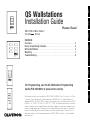 1
1
-
 2
2
-
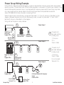 3
3
-
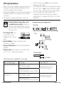 4
4
-
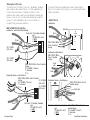 5
5
-
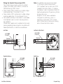 6
6
-
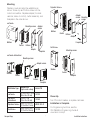 7
7
-
 8
8
-
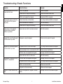 9
9
-
 10
10
-
 11
11
-
 12
12
-
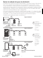 13
13
-
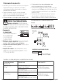 14
14
-
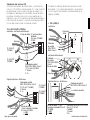 15
15
-
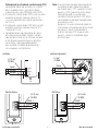 16
16
-
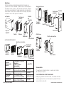 17
17
-
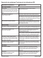 18
18
-
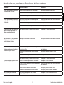 19
19
-
 20
20
-
 21
21
-
 22
22
-
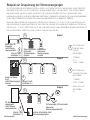 23
23
-
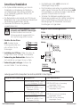 24
24
-
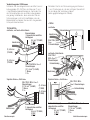 25
25
-
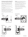 26
26
-
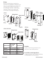 27
27
-
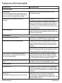 28
28
-
 29
29
-
 30
30
-
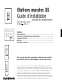 31
31
-
 32
32
-
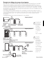 33
33
-
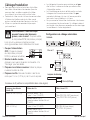 34
34
-
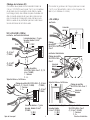 35
35
-
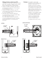 36
36
-
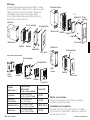 37
37
-
 38
38
-
 39
39
-
 40
40
-
 41
41
-
 42
42
-
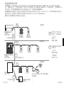 43
43
-
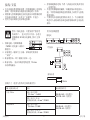 44
44
-
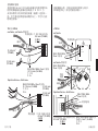 45
45
-
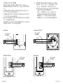 46
46
-
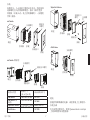 47
47
-
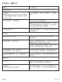 48
48
-
 49
49
-
 50
50
-
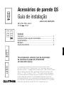 51
51
-
 52
52
-
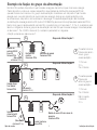 53
53
-
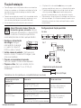 54
54
-
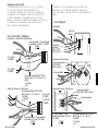 55
55
-
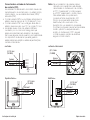 56
56
-
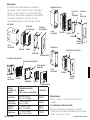 57
57
-
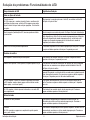 58
58
-
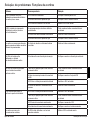 59
59
-
 60
60
-
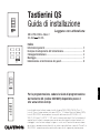 61
61
-
 62
62
-
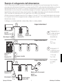 63
63
-
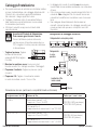 64
64
-
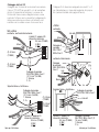 65
65
-
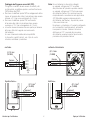 66
66
-
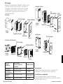 67
67
-
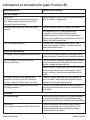 68
68
-
 69
69
-
 70
70
-
 71
71
-
 72
72
-
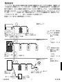 73
73
-
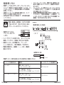 74
74
-
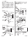 75
75
-
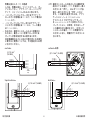 76
76
-
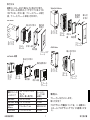 77
77
-
 78
78
-
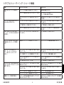 79
79
-
 80
80


Lutron Electronics Architrave QSWA-KP5-DN Guía de instalación
- Categoría
- Juguetes
- Tipo
- Guía de instalación
en otros idiomas
- français: Lutron Electronics Architrave QSWA-KP5-DN Guide d'installation
- italiano: Lutron Electronics Architrave QSWA-KP5-DN Guida d'installazione
- English: Lutron Electronics Architrave QSWA-KP5-DN Installation guide
- Deutsch: Lutron Electronics Architrave QSWA-KP5-DN Installationsanleitung
- português: Lutron Electronics Architrave QSWA-KP5-DN Guia de instalação
- 日本語: Lutron Electronics Architrave QSWA-KP5-DN インストールガイド
Artículos relacionados
-
Lutron Electronics QSGR-8D Quick Installation And Operation Manual
-
 Lutron Electronics QS Timeclock Quick Installation And Operation Manual
-
 Lutron Electronics GRAFIK Eye QS Quick Installation And Operation Manual
-
 Lutron Electronics SO-2B Guía de instalación
-
 Lutron Electronics HOMEWORKS H4P5-HRL-120 Installation Instructions Manual
-
 Lutron Electronics LR-TEMP-FLSH Guía de instalación
-
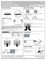 Lutron Electronics EcoSystem 5-Series Guía de instalación
-
Lutron GRX-CESO Installation And Setup Instructions
-
Lutron Electronics GRAFIK 6000 Installation Instructions Manual
-
 Lutron Electronics CS-YJ-4GC-WH Setup Manual


Otros documentos
-
Lutron QSN-2ECO-120-D Guía de instalación
-
Lutron QSFC-EDU-BP-C Wire-Free Roller Shade Electronic Drive Unit Manual de usuario
-
Lutron Roller 100 Manual de usuario
-
Lutron Q-POE-8 PoE Switch Manual de usuario
-
AMX CCD-W6BRL Guía de instalación
-
Wallbox Commander 2S CMX2-0-2-4-8-S02 Charging Station Instrucciones de operación
-
EUCHNER Botoneras HBA/HBM Instrucciones de operación
-
Cooper Lighting WWBZIG WaveLinx Wireless Wallstation Battery Powered Guía de instalación
-
-
WEG SRW01 Guía del usuario