Craftsman 139536481DM El manual del propietario
- Categoría
- Abridor de puerta de garage
- Tipo
- El manual del propietario

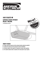
Owner's Manual/ManualDel Propietario
CRRFTSMRN °
1/2 HP
315 MHZGARAGEDOOROPENER
ABRIDORDEPUERTADECOCHERADE315 MHZ
ForResidentialUse0nly/S61oparausoresidencial
Model/Modelo• 139.536481DM
I"I'I
I""
Oo
I"t"l
Oo
"10
Z_
I""
Readandfollowall safetyrulesand
operatinginstructionsbeforefirstuseof
thisproduct.
Fastenthe manualnearthegaragedoor
after installation.
Leery seguirtodaslas reglasdeseguridad
y lasinstruccionesdeoperaci6n antesde
usaresteproductoporprimeravez.
Guardarestemanualcercade la puerta de
la cochera.
Periodic checksof theopener arerequ
to ensuresafeoperation.
ired
Sedebenrealizarrevisionesperi6dicas
delabridordepuertas paraasegurarsu
operaci6n segura.
oQ°s
Sears, Roebuck and Co., Hoffman Estates, IL 60179 U.S.A
www.sears.com/craftsman

TABLE OF CONTENTS
Introduction 2-5
Safetysymbol and signal word review ..................... 2
Preparingyour garagedoor ............................. 3
Tools needed......................................... 3
Planning .......................................... 4-5
Carton inventory ...................................... 6
Hardware inventory.................................... 7
Assembly 8-11
Assemblethe rail and attachthe pulleybracket .............. 8
Install the trolley ...................................... 9
Attachthe rail to the motor unit .......................... 9
Install the chain/cableand the sprocket cover .............. 10
Tighten the chainand cable ............................ 11
Installation 11-26
Installation safety instructions .......................... 11
Determinethe headerbracket location .................... 12
Install the header bracket .............................. 13
Attachthe rail to the headerbracket ...................... 14
Position theopener................................... 15
Hangthe opener ..................................... 16
Install the door control ................................ 17
Install the light ...................................... 18
Attachthe emergency releaseropeand handle.............. 18
Electricalrequirements ................................ 19
Install the ProtectorSystem-_........................ 20-22
Fastenthe door bracket............................. 23-24
Connectthedoor arm to the trolley ................... 25-26
Adjustment 27-29
Adjust thetravel limits ................................ 27
Adjust theforce...................................... 28
Testthe safety reversal system.......................... 29
Testthe ProtectorSystem®............................. 29
Operation 30-34
Operationsafety instructions ........................... 30
Usingyour garagedoor opener ......................... 30
Usingthe wall-mounted door control ..................... 31
To open thedoor manually............................. 31
Careofyour garagedoor opener ........................ 32
Havinga problem? ................................... 33
Diagnosticchart ..................................... 34
Programming 35-36
To add or reprogram a hand-held remotecontrol............ 35
To eraseall codes.................................... 35
3-function remotes................................... 35
To add, reprogram or changea KeylessEntry PIN ........... 36
Repair Parts 37-38
Railassembly parts................................... 37
Installation parts ..................................... 37
Motor unit assembly parts ............................. 38
Accessories 39
Warranty
RepairPartsandService
39
Back Cover
INTRODUCTION
SafetySymbolandSignal WordReview
This garagedoor opener has beendesignedand testedto offer safe service providedit is installed, operated,maintained and testedin
strict accordancewith the instructions and warnings contained in this manual.
Mechanical
Electrical
Whenyou seetheseSafetySymbols and Signal Words on the
following pages,they will alertyou to the possibility of serious
injury or deathif you do not comply with the warnings that
accompanythem. The hazardmay come from something
mechanicalor from electric shock. Readthe warnings carefully.
Whenyou seethis Signal Word on the following pages,it will alert
you to the possibility of damageto your garagedoor and/orthe
garagedoor opener ifyou do not comply with the cautionary
statementsthat accompany it. Readthem carefully.

Preparing your garage door
Beforeyou begin:
• Disablelocks.
• Removeany ropesconnectedto garage door.
• Completethe followingtest to make sureyour garagedoor is
balancedand is not sticking or binding:
1. Lift the door about halfwayas shown. Releasethe door. If
balanced, it should stay in place,supported entirely by its
springs.
2. Raiseand lowerthe door to seeif there is any binding or
sticking.
If your door binds, sticks, or is out of balance,call a trained door
systems technician.
To prevent possible SERIOUSINJUREor DEATH:
• ALWAYScalla trained door systems technician if garage
door binds, sticks, or is out of balance.An unbalanced
garage door may NOTreversewhen required.
• NEVERtry to loosen, move or adjust garagedoor, door
springs, cables,pulleys, bracketsor their hardware,ALL of
which are under EXTREMEtension.
• DisableALL locks and remove ALL ropes connectedto
garage door BEFOREinstalling and operating garagedoor
opener to avoid entanglement.
To prevent damageto garagedoor and opener:
• ALWAYSdisablelocks before installing and operating the
opener.
• ONLYoperategaragedoor openerat 120V, 60 Hzto avoid
malfunction and damage.
SectionalDoor
One-Piece Door
Tools needed
Duringassembly, installation and adjustment of the opener,
instructions will call for handtools as illustrated below.
Stepladder
Level (optional)
Tape Measure
Drill 3/16", 5/16"
i_ and 5/32"
0
[_1_ Sockets and Wrench
--U 1/2", 5/8", 7/16", 9/16"
and 1/4"
Pencil
Wire Cutters
Screwdriver
Hack Saw
Adjustable End Wrench

P_nnmg
Identify the type and height of your garagedoor. Surveyyour
garageareato seeif any of the conditions below applyto your
installation. Additional materials may be required.You may find it
helpfulto refer backto this pageand the accompanying
illustrations asyou proceedwith the installation ofyour opener.
Dependingon your requirements, thereare several installation
steps which may call for materials or hardwarenot included in the
carton.
• Installation Step 1- Lookat the wall or ceiling abovethe garage
door. The headerbracketmust besecurely fastenedto structural
supports.
• Installation Step5 - Doyou havea finished ceiling in your
garage? If so, a support bracketand additional fastening
hardwaremay be required.
• Installation Step 10- Dependingupon garage construction,
extension bracketsor wood blocks may be neededto install
sensors.
• Installation Step 10- Alternate floor mounting of the safety
reversingsensor will require hardwarenot provided.
Doyou havean accessdoor in addition to the garagedoor? If
not, Model53702 OutsideQuick Releaseis required.See
Accessories page.
Look atthe garagedoor where it meetsthe floor. Any gap
betweenthefloor and the bottom of the door must not exceed
1/4" (6mm). Otherwise,the safety reversalsystem may not
work properly. SeeAdjustment Step3. Flooror door should be
repaired.
SECTIONALDOORINSTALLATIONS
• Doyou havea steel,aluminum, fiberglass or glass paneldoor?
If so, horizontal and vertical reinforcement is required
(Installation Step11).
• The openershould be installed abovethe center of the door. If
there is a torsion spring or center bearing platein theway of the
headerbracket, it may be installedwithin 4 feet (1.2 m) to the
left or right of the door center.See Installation Steps 1 and 11.
• If your door is more than 7 feet (2.1 m) high, see rail extension
kits listed on Accessoriespage.
SECTIONALDOORINSTALLATION
Horizontal and vertical reinforcement
is neededfor lightweight garage doors
(fiberglass, steel, aluminum, door with
glass panels, etc.). Seepage 23 for details.
Header Wall
Slack in chain tension
is normal when
garage door is closed.
Extension Spring
OR
Torsion Spring
FINISHEDCEILING
Support bracket &
fastening hardware
is required.
See page 16.
Motor unit
Vertical
Centerline
ofGarage
Door
Wall-
mounted
Door
Control
4
ty Reversing Sensor
Gap between floor
and bottom of door
must not exceed 1/4" (6 mm).
Safety Reversing
Sensor
Access Door
0
_ Header CLOSED POSITION
Bracket
/ Trolley
.......r.......
Garage /
_/._ _ G_age // Chain
_ r-',-_-/ Spring_o/
_////._1/////A /j/Y-_tr_irght --B_]eera%nCy
//_/ Arm Rope&Handle
He_der __Curved d'm
Wall _"N_I \ Door
L\N I Door Arm
Garage__l Bracket
Door

Planning (Continued)
ONE-PIECEDOORINSTALLATIONS
• Generally,a one-piecedoor doesnot require reinforcement. If
your door is lightweight, referto the information relating to
sectional doors in Installation Step11.
• Dependingon your door's construction, you may need
additional mounting hardwarefor the door bracket(Step 11).
Without a properlyworking safety reversalsystem, persons
(particularly small children) could be SERIOUSLYINJUREDor
KILLEDby a closing garage door.
• The gap betweenthe bottom of the garagedoor and the
floor MUSTNOTexceed1/4" (6 mm). Otherwise,the safety
reversalsystem may NOTwork properly.
• Thefloor orthe garagedoor MUSTbe repairedto eliminate
the gap.
ONE-PIECEDOORWITHOUTTRACK
Header
Wall
Slack in chain tension
is normal when
garage door is closed.
__ Wall-
mounted
}oor
;ontr
I
_afeb _-
ReversingSensor
andbottomof
Safety doormustnotexceed1/4"(6mm)
ReversingSensor
FINISHEDCEILING
Support bracket
& fastening
hardware is required.
See page 16.
Access
Door
0
Motor Unit
CLOSEDPOSITION
Cable
Pulley Bracket
Trolley
Door j j
I I Emergency
. Release
_ed RR_lDeeaS_Hand,e
_nr-- Hope_ uanole
,_ Arm Arm
Garage
Door
ONE-PIECEDOORWITHTRACK
_. _ _ Slack in chain tension is normal when _
Header
Fo eeo wa,,
IlI II !lira I I I Garage--
__ Door
andbottomofdoor Sensor
----"- Safety must not
/
Reversing Sensor exceed 1/4" (6 mm) /
d
5
CLOSEDPOSITION
Cable Cable Trolley Chain
Pulley Bracket I I_
.
"X'_ Header Curved _ R!il
Bracket Door Arm "_-/ I ....
Y////i:J Door Straight ,..J...
N i c,otooor
"//A Arm
EmergencyRelease
Rope & Handle

CartonInventory
Your garage door opener is packagedin two cartonswhich contain
the motor unit and all parts illustrated below. Accessorieswill
dependon the model purchased.If anything is missing, carefully
checkthe packing material. Parts may be stuck in the foam.
Hardwarefor assembly and installation is shown on the next page.
Savethe carton and packing material until installation and
adjustment iscomplete.
SECURITY÷_
3-Function Remote Control
with Visor Clip (2)
Door Control Button
Door Bracket Plate
Mounting Bracket and
With Square Holes (2) The Protector System® Literature
(2) Safety Reversing Sensors Straight Door
(1 Sending Eyeand 1 Receiving Eye)
with 2-Conductor White & White/Black Arm Section
Bell Wire attached

HardwareInventory
Separateall hardwareand group as shown below for theassembly and installation procedures.
ASSEMBLYHARDWARE
Washered Bolt Hex Bolt Nut
5/16"-18xl/2" (2) 5/16"-18x7/8" (3) 5/16"-18 (5)
(mounted in motor unit)
Threaded
Trolley Shaft (1)
Carriage Bolts
1/4"-20xl/2" (4)
@
Lock Washer
5/16" (4)
i
Master Link (2)
@
Lock Nut
1/4"-20x7/16" (4)
5/16"-9xl -5/8" (2)
INSTALLATIONHARDWARE
Hex Bolt
5/16"-18x7/8" (4) Nut 5/16"-18 (6) Lock Washer 5/16" (6)
0
Ring
Fastener (3)
Self-Threading Screw
1/4"-14x5/8" (2)
Clevis Pin
5/16"x2-3/4" (1)
1/4 x1-1/2" (4)
IIIIIIIIIIIIIIIIIID
Hex Bolt
1/4-20x1-1/2" (2)
CarriageBolt
5/16"-18x2-1/2"(2)
Carriage Bolts
1/4"-20xl/2" (4)
Screw
#10-32x3/8" (4)
Clevis Pin
5/16"x1-1/4"(1)
©
Lock Nut
1/#'-20 (4)
@
Lock Nut
#10x32 (4)
oB
Handle
I//11/f
Drywall Anchors (2) Rope
°D
Clevis Pin
5/16"x1" (1)
Wing Nut
1/4x20 (2)
Insulated Staples
(Not shown)

ASSEMBLY STEP 1
Assemble the Rail and
Attach the Cable Pulley Bracket
To avoidinstallationdifficulties,do notrunthegaragedoor
openeruntil instructedto doso.
1. Align the three rail sections on a flat surfaceexactly asshown.
Front and back sections are interchangeablefor easeof
assembly.
2. Insert the carriagebolts so thesquare bolt
necksseat in the squareholes in the rail
U
sections and pass through the round holes in
thecenter section rail. Make sure holtnecks
areseatedin the squareholesandrails are
alignedbeforeyoutightenlocknuts.
Improper assembly cancausejerky trolley
operation, noise and/or nuisancedoor
reversals.
3. Assemblelock nuts, ensurealignment and
tighten.
NOTE:If rail is not assembled exactlyasshown, trolley will not
travel smoothly along length of rail or it will hit against nuts.
4. Position the cable pulleybracketon thefront end of the rail as
shown. Fastensecurelywith the hardwareshown.
NOTE:Whentightening thebolts, be sure to keepbracket
parallel to the rail. Otherwise, therail may bow whenthe opener
is operated.
HARDWARESHOWNACTUALSIZE
Q
Lock Nut
1/4"- 20 x 7/16"
,1111111111D
Hex Screw
5/16"- 18 x 7/8"
Carriage Bolts
1/4"- 20x 1/2"
Nut
5/16"- 18
RAILBACK
(TOOPENER)
Rail
(CenterSection)
1/4" Lock Nut
\
\
Brace
Rail
(End Section)
Rail
(End Section)
Cable pulley bracket
attaches to FRONT
ENDof Rail
RAILFRONT
(TODOOR)
Brace
Square Carriage
Bolt Holes
Lock Washer
5/16"

ASSEMBLY STEP 2
Install the Trolley
Attachthe trolley threadedshaftto thetrolley with the lock
washer and nuts as shown.
Lock Inner Nut
Asa temporary stop, insert a screwdriver into the hole in the Washer5/16"
front end of the rail. 5/16"
Slidethe trolley assembly along the rail to the Outer Nut _ Trolley __
screwdriver stop. 5/16" _j Thh_ded _""_'_ T_lle
NOTE:If trofleyhits against any nuts on the rail, the _ _ _ /.2_"'" _ Y
bolts and nuts wereattachedfrom the wrongside Trolley ,_ _ /_/ /
and must be reposifioned.ReviewAssembly Step ( _-/_ _ __/ P
'
/_ Nut
St°O 5/16-18
Lock Washer
5/16"
ASSEMBLY STEP 3
Attachthe Rail totheMotorUnit
Toavoid installation difficulties, do not run the garagedoor opener
until instructed to do so.
• Placethe opener on packing materialto protect the cover. For
convenience,put a support under the cablepulley bracket.
• Removethe two washered bolts mounted in top of motor unit.
• Align the holesin the backsection of the rail with the holesin
the motor unit.
• Fastenthe rail with the two washered bolts previously removed.
Tighten securely.
Use onlythesebolts! Useof anyotherbolts will causeserious
damageto dooropener.
• Inserta 5/16"-18x7/8" hex bolt into the cover protection bolt
hole in the rail as shown. Tighten securelywith a 5/16" lock
washer and nut.
NOTE:Thisbolt prevents trolley over-traveLKeepa 2" (5 mm)
minimum betweenthe trolley and this bolt whenadjusting travel
limits (seepage27).
HARDWARESHOWNACTUALSIZE
Hex Bolt Nut
5/16"-18x7/8" 5/16"-18
Lock Washer
5/16"
To avoid serious damageto opener,ONLYusebolts/fasteners
mounted in top of motor unit.

ASSEMBLY STEP 4
Install the Chain/CableandAttachthe SprocketCover
INSTALLINGTHECHAIN/CABLE
1. Pullthe cable loop from the carton andfasten it to thetrolley
with a master link from the hardwarebag (Figure1).
• Push pins of master link LeaveChain&
bar through cableloop and
hole in front end of trolley.
• Push masterlink capover
pins and past pin notches.
• Slide clip-on spring over
capand onto pin notches
until both pins are securely
locked in place.
Cable Inside
Dispensing
Cartonto
king
KeepChain and Cable
Taut When Dispensing
2. With the trolley against the screwdriver, dispensethe cable
around the pulley.
3. Continue along the rail and aroundthe motor unit sprocket
(Figure2). The sprocket teeth must engagethe chain. Continue
forward to the trolley threadedshaft.
4. Usethe second master link to connect the chainto the flat end
of the shaft (Figure1). Checkto makesurethe chainis not
twisted.
5. Removethe screwdriver.
ATTACHINGTHESPROCKETCOVER
Insert the backtab in the slot on the back of the mounting plate.
Squeezethe cover slightly and insert the front tab (Figure3).
To avoid possible SERIOUSINJURYto fingers from moving
garagedoor opener:
• ALWAYSkeephandclear of sprocket while operatingopener.
• Securelyattachsprocket cover BEFOREoperating.
FigureI MasterLink
Clip-On Spring,
Master"_
Master Link Flat end Link Cap i _ -
Clip-On Spring , of Trolley _ yf
Master _ _ Threaded Shaft.x¢_.,, y._..
_boLi:k Cap[_, _'_ _,i" _Rt! Chain
f -¢--_._ d:Y'<"-Master
INSTALLCHAIN& CABLE
INTHIS DIRECTION
Figure3
Sprocket
Cover
Figure2 MotorUnit
Sprocket
10

ASSEMBLY STEP 5
Tightenthe Chainand Cable
• Spin the inner nut and lock washerdown the threadedshaft,
awayfrom thetrolley.
• Totighten the chain, turn outer nut in the direction shown. As
youturnthe nut,keepthe chainfromtwisting.
• Whenthe chain is approximately 1/2" (13 mm) abovethe base
of the rail at its midpoint, re-tighten the inner nutto securethe
adjustment.
Sprocket noisecanresultif chainis eithertoo looseor tootight.
Wheninstallation is complete,you may notice some chain droop
with the door closed.This is normal. If the chain returns to the
position shown whenthe door is open, do not re-adjust thechain.
NOTE:During future maintenance,ALWAYSpuff the emergency
releasehandle to disconnect trolley beforeadjusting chain.
Youhavenowfinishedassemblingyourgaragedooropener.
Pleaseread thefollowingwarningsbeforeproceedingtothe
installationsection.
Lock
OuterNut Washer InnerNut
To Tighten Outer Nut _ ._l._,J __
rL_ ...............'__"",_'_"'T o T,'g'ht'e'n....
oj Inner Nut
Chain
----1/2" (13 mm)
Base!f Rail
INSTALLATION
IMPORTANTINSTALLATIONINSTRUCTIONS
ToreducetheriskofSEVEREINJURYorDEATH:
1. READAND FOLLOWALL INSTALLATIONWARNINGSAND
INSTRUCTIONS.
2. Install garagedoor opener ONLYon properly balancedand
lubricated garagedoor. An improperly balanceddoor may
NOTreversewhen required and could result in SEVERE
INJURYor DEATH.
3. ALL repairsto cables,spring assembliesand other
hardware MUSTbe madeby a trained door systems
technician BEFOREinstalling opener.
4. DisableALL locks and removeALL ropes connectedto
garagedoor BEFOREinstalling openerto avoid
entanglement.
5. Install garagedoor opener 7 feet (2.13 m) or more above
floor.
6. Mount emergency releasewithin reach, but at least 6 feet
(1.8 m) abovethe floor and avoiding contactwith vehicles
to avoidaccidental release.
7. NEVERconnectgarage door opener to powersource until
instructed to do so.
8. NEVERwearwatches, rings or loose clothing while
installing or servicing opener.They could be caught in
garage door or opener mechanisms.
9. Install wall-mounted garagedoor control:
• within sight of the garage door.
• out of reachof children at minimum height of 5 feet
(1.5 m).
• awayfrom ALL moving parts of the door.
10. Placeentrapment warning labelon wall next to garage
door control.
11. Placemanual release/safetyreversetest label in plain
view on inside of garage door.
12. Uponcompletion of installation, test safety reversal
system. Door MUST reverseon contact with a 1-1/2"
(3.8 cm) high object (or a 2x4 laid flat) on the floor.
11

INSTALLATION STEP 1
Determinethe HeaderBracketLocation
To prevent possible SERIOUSINJURYor DEATH:
• HeaderbracketMUSTbe rigidly fastenedto structural
support on headerwall or ceiling, otherwise garagedoor
might NOTreversewhen required. DONOTinstall header
bracketover drywall.
• Concreteanchors MUSTbe used if mounting headerbracket
or 2x4 into masonry.
• NEVERtry to loosen, move or adjust garagedoor, springs,
cables,pulleys, brackets,or their hardware,ALL of which are
under EXTREMEtension.
• ALWAYScall atrained door systems technician if garage
door binds, sticks, or is out of balance.An unbalanced
garagedoor might NOTreversewhen required.
nstallation proceduresvary according to garagedoor types.
Follow the instructions which applyto your door.
1. Closethe door and mark the insidevertical centerline of the
garagedoor.
2. Extendthe line onto the headerwall abovethe door.
Youcanfastenthe headerbracketwithin4 feet (1.22 m) of
theleft or rightofthe doorcenter onlyif a torsionspringor
centerbearingplate isin the way;or youcanattachittothe
ceiling(see page 13) when clearanceisminimal. (It may be
mountedonthewall upsidedownif necessary,to gain
approximately1/2"(13 ram).
If you needto install the headerbracketon a 2x4 (on wall or
ceiling), uselag screws (not provided) to securely fastenthe
2x4to structural supports asshown hereand on page 13.
3. Openyour door to the highest point of travel as shown. Draw an
intersecting horizontal line on the headerwall abovethe high
point:
• 2"(5 cm) abovethe high point for sectionaldoor and one-
piecedoor with track.
• 8"(20 cm) abovethe high point for one-piecedoor without
track.
This height will providetravel clearancefor the top edgeofthe
door.
NOTE:If thetotal number of inches exceedstheheight availablein
your garage,use themaximum height possible, or referto page 13
for ceiling installation.
Unfinished
Ceiling
Header Wall
VerticalCenterline
ofGarageDoor
HeaderWall
HighestPoint
of Travel
Sectional doorwith curved track
L_Wall
:_ )
Highest
Point
ofTravel
Hardware
One-piecedoorwithouttrack:
jambhardware
OPTIONAL
CEILING
MOUNT
FOR
HEADER
BRACKET
2x4
Structural
Supports
H
HeaderWall Track
t
ofTravel
One-piece door with horizontal track
HeaderWall
',- 8" (20cm)
L____:=.;_,
Door
:l
Pivot
One-piece door without track:
pivot hardware
', Highest
,, Point
" of Travel
12

INSTALLATION STEP 2
Install theHeaderBracket
You canattachthe headerbracketeitherto thewall abovethe
garagedoor, or to the ceiling. Followthe instructions which will
work best for your particular requirements. Donot install the
headerbracketover drywall. If installingintomasonry,use
concreteanchors(notprovided).
WALLHEADERBRACKETINSTALLATION
• Centerthe bracketon the vertical centerlinewith the bottom
edgeof the bracket on the horizontal line asshown (with the
arrow pointing toward the ceiling).
• Mark the vertical set of bracket holes(do not usethe holes
designatedfor ceiling mount). Drill 3/16" pilot holesand fasten
the bracketsecurelyto a structural support with the hardware
provided.
HARDWARESHOWNACTUALSIZE
LagScrew
5/16"x9x1-5/8"
CEILINGHEADERBRACKETINSTALLATION
• Extendthevertical centerline onto the ceiling as shown.
• Centerthe bracketon the vertical mark, no more than 6"(15 cm)
from the wall. Makesurethe arrow is pointing toward the wall.
Thebracketcan be mounted flush againstthe ceiling when
clearanceis minimal.
• Mark the side holes. Drill 3/16" pilot holesand fasten bracket
securelyto a structural support with the hardwareprovided.
Ceiling Mounting Holes
CEILI MOiM'_UN NLY
o@o
Wall Mounting Holes
G MOUNT ONLY
Optional_
Wail MountingHoles
Header
-- Wall
2x4
Structural
Support
Horizontal
Line _ /
/
/
/
/
.. 1/
HighestPoint of
Garage DoorTravel
Vertical
Centerline
of Garage Door
LagScrews
5/16"-9xl-5/8"
Door Spring
Garage
- Door -
Vertical
Centerline
ofGarageDoor
* _" __ __ _* _ _ //_ - FinishedverticaiCeiling-
_ _ _/_ Header Centerline
Bracket of Garage Door
6" (15 cm) Maximur
Door
Spring
LagScrews
5/16"-9xl -5/8"
HeaderWall
\ of Garage Door
13

Header Wall
Bracket
Cable
Pulley
Bracket
INSTALLATION STEP 3
Attachthe Rail to the HeaderBracket
• Position the opener on the garagefloor below the header
bracket. Usepacking material as a protective base. NOTE:If the
door spring is in the wayyou'll needhelp. Havesomeone hold
the openersecurely on a temporary support toaflow the raftto
clear thespring.
• Position the rail bracketagainst the headerbracket.
• Align the bracketholes and join with a clevis pin as shown.
• Insert a ring fastenerto secure.
-- Rail
Clevis Pin
5/16"x2-3/4"
Ring Fastener
Header _.
Bracket 0
i
Cable
Pulley
Bracket
Rail
__ Garage
Door
-- Openercartonor
TemporarySupport
HARDWARESHOWNACTUALSIZE
Clevis Pin
5/16"x2-3/4"
0
Ring Fastener
14

INSTALLATION STEP 4
Positionthe Opener
Follow instructions which applyto your door type as illustrated.
SECTIONALDOORORONE-PIECEDOORWITH TRACK
A 2x4 laid flat is convenientfor setting an ideal door-to-rail
distance.
• Removefoam packaging.
• Raisethe openeronto a stepladder.You will needhelp at this
point if the ladder is not tall enough.
• Openthedoor all the way and placea 2x4 laidflat on thetop
section beneaththe rail.
• If the top section or panelhits thetrolley when you raise
thedoor, pull down on the trolley releasearm to disconnect
inner and outer sections. Slide the outertrolley toward the
motor unit. Thetrolley can remaindisconnected until
Installation Step12 iscompleted.
Trolley
v " _ ' -- ReleaseArm --
ENGAGED RELEASED
To prevent damageto garagedoor, rest garagedoor opener rail
on 2x4 placedon top section of door.
Rail
2x4 is used to determine
the correct mounting height
from ceiling.
ONE-PIECEDOORWITHOUTTRACK
A 2x4 on its side is convenientfor setting an ideal door-to-rail
distance.
• Removefoam packaging.
• Raisethe openeronto a stepladder.You will needhelp at this
point if the ladder is not tall enough.
• Openthe door all the way and placea 2x4 on its side on the top
section of the door beneaththe rail.
• Thetop of the door should be levelwith the top of the motor
unit. Do not position the opener morethan 4" (10 cm) abovethis
point.
i
Header
2x4 is used to determine
the correct mounting height
from ceiling.
15

INSTALLATION STEP 5
HangtheOpener
Three representativeinstallations are shown. Yours may be
different. Hangingbrackets should be angled (Figure1) to provide
rigid support. Onfinished ceilings (Figure2 and Figure3), attach a
sturdy metal bracketto structural supports beforeinstalling the
opener.This bracket andfastening hardwareare not provided.
1. Measurethe distancefrom eachside of the motor unit to the
structural support.
2. Cut both piecesof the hanging bracketto required lengths.
3. Drill 3/16" pilot holes in the structural supports.
4. Attachone end of eachbracketto a support with
5/16"-18xl -7/8" lagscrews.
5. Fastenthe openerto the hanging bracketswith 5/16"-18x7/8"
hexbolts, lock washersand nuts.
6. Checkto makesurethe rail is centered overthe door (or in
line with the headerbracket if the bracketis notcentered above
thedoor).
7. Removethe 2x4. Operatethe door manually. If thedoor hits the
rail, raisethe headerbracket.
NOTE:DONOTconnectpower to openerat this time.
HARDWARESHOWNACTUALSIZE
,lllllllllID@
Hex Bolt
5/16"-18x7/8" Nut 5/16"-18 LockWasher 5/16"
To avoid possible SERIOUSINJURYfrom a falling garagedoor
opener,fasten it SECURELYto structural supports of the
garage.Concreteanchors MUSTbe usedif installing ANY
brackets into masonry.
Figure I ructural
Supports
Measure _
Distance
Lag Screws
5/16"-18xl -7/8"
Bolt 5/16"-18x7/8"
Lock Washer 5/16"
Nut 5/16"-18
Bolt 5/16"-18x7/8 _-"
Lock Washer 5/16"
Nut 5/16"-18
FINISHEDCEILING
Provided)
Lock Washer 5/16"
Nut 5/16"-18
gScrews
FINISHEDCEILING
Bolt 5/16"-18x7/8"
Lock Washer 5/16"
Nut 5/16"-18
, (Not Provided)
Bolt 5/16"-18x7/8"
Lock Washer 5/16"
16

INSTALLATION STEP 6
Install theDoorControl
Locatedoor control within sight of door, at a minimum heightof 5
feet (1.5 m) where small children cannot reach,awayfrom moving
parts of door and door hardware. If installing into drywall, drill
5/32" holesand usethe anchors provided.
1. Strip 1/4" (6 mm) of insulationfrom one endof bell wire and
connectto the two terminal screws on back of door control by
color: white to 2 and white/red to 1.
2. DoorControlButton:Fastensecurelywith screws 6ABx1-1/2".
3. (Forstandardinstallationonly)Runbell wire upwall and
acrossceiling to motor unit. Useinsulated staplesto secure
wire in severalplaces.Do not piercewire with a staple, creating
a short or opencircuit.
4. Connectthe bell wire to theterminal screws on the motor unit
panel:white to 2;white/red to 1.
5. Position the antennawire asshown.
To prevent possible SERIOUSINJURYor DEATHfrom
electrocution:
• Besure power is NOTconnectedBEFOREinstalling door
control.
• ConnectONLYto 24 VOLTlow voltage wires.
To prevent possible SERIOUSINJURYor DEATHfrom a closing
garagedoor:
• Install door control within sight of garagedoor, out of reach
of children at a minimum height of 5 feet (1.5 m), and away
from ALL moving parts of door.
• NEVERpermit children to operateor playwith door control
push buttons or remote control transmitters.
• Activate door ONLYwhen it can be seenclearly,is properly
adjusted,and thereare no obstructions to door travel.
• ALWAYSkeepgaragedoor in sight until completely closed.
NEVERpermit anyoneto cross path of closing garagedoor.
HARDWARESHOWNACTUALSIZE
Drywall Anchors
(drywall installation)
Insulated Staples
(Not shown)
Terminal
Screws
(BACKVIEW)
DOORCONTROLBUTTON
2-Conductor
Bell Wire
Opener
Terminal Screws
Back Panel
of Opener
Antenna
17

INSTALLATION STEP 7
Install theLight
• Install a 75 watt maximum light bulb in thesocket. Lightsize is
A19,standard neck only Thelight will turn ONand remain lit for
approximately 4-1/2 minuteswhen power is connected. Then
the light will turn OFF.
• Apply slight pressureon the sides of the lensand slide the tabs
into the slots in the end panel (Seeillustration).
• To remove,reversethe procedure. Usecareto avoidsnapping
off lenstabs.
• UseA19, standard neck garagedoor opener bulbs for
replacement.
NOTE:Useonly a standard light bulb. Theuse ofa short neck or
speciafitylight bulb may overheatthe endpanelor light socket.
To prevent possible OVERHEATINGof the endpanelor light
socket:
• DONOTuseshort neckor specialty light bulbs.
• DONOTuse halogenbulbs. UseONLYincandescent.
To prevent damageto the opener:
• DONOTuse bulbs larger than 75W.
• ONLYuseA19 size bulbs.
LensGuide
Light
Lens Slot
LensTab
75Watt Max.
Light Bulb
INSTALLATION STEP 8
Attachthe EmergencyRe/easeRopeand Hand/e
• Threadone end of the rope through the holein thetop of the
redhandle so "NOTICE"readsright sideup asshown. Secure
with an overhandknot at least 1" (25 mm) from the end of the
ropeto preventslipping.
• Threadthe other endof the ropethrough the hole in the release
arm of the outer trolley.
• Adjust rope length sothe handleis 6 feet (1.8 m) abovethe
floor. Securewith an overhandknot.
NOTE:If it is necessaryto cut therope, heatsealthe cut end with
a match or lighter to prevent unraveling.
To prevent possible SERIOUSINJURYor DEATHfrom a falling
garagedoor:
• If possible, useemergencyreleasehandleto disengage
trolley ONLYwhengarage door is CLOSED.Weakor broken
springs or unbalanceddoor could result in an open door
falling rapidly and/or unexpectedly.
• NEVERuseemergency releasehandleunless garage
doorway is clear of persons and obstructions.
• NEVERuse handleto pull door open or closed. If rope knot
becomesuntied, you could fall.
Tro,,e %h° nd
Rope -- ReleaseArm
N_ _ Emergency
Overhand _ ReleaseHandle
not
18

INSTALLATION STEP 9
ElectricalRequirements
To avoid installation difficulties, do not run the opener atthis time.
To reducethe risk of electric shock, your garagedoor opener hasa
grounding type plug with athird grounding pin. This plug will only
fit into agroundingtype outlet. If the plug doesn't fit into the outlet
you have,contact a qualified electricianto installthe proper outlet.
RIGHT @ WRONG
If permanent wiring isrequiredby yourlocal code,refer tothe
following procedure.
To make a permanent connectionthrough the 7/8" holein the top
of the motor unit:
• Removethe motor unit cover screws and set the cover aside.
• Removethe attached3-prong cord.
• Connectthe black (line) wire to the screw on the brassterminal;
thewhite (neutral) wire to the screw on the silver terminal; and
theground wire to the green ground screw. The opener must
be grounded.
• Reinstallthe cover.
To avoidinstallationdifficulties,do notruntheopenerat this
time.
To prevent possible SERIOUSINJURYor DEATHfrom
electrocution or fire:
• Besure power is NOTconnectedto the opener,and
disconnect power to circuit BEFOREremoving coverto
establishpermanent wiring connection.
• Garagedoor installation and wiring MUSTbe in compliance
with ALL local electricaland building codes.
• NEVERusean extension cord, 2-wire adapter,or change
plug in ANYway to makeit fit outlet. Besure the opener is
grounded.
PERMANENTWIRING
CONNECTION
GroundTab
Green
GroundScrew
GroundWire Wire
White Wire BlackWire
19

INSTALLATION STEP 10
Install TheProtectorSysterr
The safetyreversingsensormustbeconnectedand aligned
correctlybeforethegaragedooropenerwill movein the down
direction.
IMPORTANTINFORMATIONABOUTTHESAFETYREVERSING
SENSOR
When properly connectedand aligned,the sensor will detectan
obstacle in the path of its electronic beam.Thesending eye(with
an green indicator light) transmits an invisiblelight beamto the
receivingeye(with a green indicator light). If an obstruction breaks
the light beamwhile the door is closing, the door will stop and
reverseto full open position, and the opener lights will flash
10 times.
The units must be installed insidethe garage sothat the sending
and receivingeyesface eachother acrossthe door, no more than
6" (15 cm) abovethe floor. Eithercan be installed on the left or
right of the door as long asthe sun nevershines directly into the
receivingeyelens.
The mounting bracketsare designedto clip onto thetrack of
sectional garagedoors without additional hardware.
Besure poweris NOTconnectedto the garagedoor opener
BEFOREinstalling the safety reversing sensor.
To prevent SERIOUSINJURYor DEATHfrom a closing garage
door:
• Correctly connect and align the safety reversing sensor.This
requiredsafety device MUSTNOTbedisabled.
• Installthe safety reversingsensor so beam is NOHIGHER
than 6"(15 cm) abovegaragefloor.
If it is necessaryto mount the units on thewall, the brackets must
be securelyfastenedto a solid surface such asthe wall framing.
Extensionbrackets (seeaccessories)are availableif needed.If
installing in masonryconstruction, add a pieceof wood at each
location to avoiddrilling extra holes in masonry if repositioning is
necessary.
Theinvisible light beam pathmust be unobstructed. No partof the
garagedoor (or door tracks, springs, hinges, rollers or other
hardware)may interrupt the beamwhile the door isclosing.
Safety Reversing Sensor
6" (15cm) max. above floor
Invisible Light Beam
Protection Area
Safety Reversing Sensor
6" (15 cm) max. above floor
Facingthe doorfrom insidethe garage
2O

Insta//ing the Brackets
Figure1,2 and 3 show recommendedassembly of bracket(s) and
"C" wrap basedon the wallinstallation of the sensorson eachside
of the garagedoor asshown on page 20, or on the garagedoor
tracks themselves.
Figure4 and 5 arevariations which may fit your installation
requirements better. Makesurethewrapsand bracketsare
alignedsothesensorswill face eachotheracrossthegarage
door.
Garage Wallor Door TrackInstallation
1. Fastenthe "C" wraps to the mounting brackets havingsquare
holes, using the hardwareshown in Figure1.
Garage WallInstallation
2. Connecteachassembly to a slotted bracket,using the hardware
show on Figure2. Notealignment ofbracketsfor left and right
sidesofdoor.
3. Fingertighten the lock nuts.
4. Use bracketmounting holesas a templateto locateand drill (2)
3/16" diameterpilot holes on both sides of the garagedoor,
4"-6"abovethe floor butnot exceeding6"(seewarning on
page20).
5. Attachbracket assemblywith 1/4"x1-1/2"lag screws asshown
in Figure2.
6. Adjust right and left bracketassembliesto thesame distance
out from mounting surface. Makesure all door hardware
obstructions arecleared.Tighten the nuts securely.
GarageDoorTrackInstallation
Discardslotted bracket. Drill 3/8" holesin eachtrack andfasten
securelywith hardwareas shown in Figure3.
Figure1 GarageWALLor DOORTrackInstallation
Mounting Bracket
X_\ With Square Holes "C"Wrap
_lo_i3N2uts_ :'__#10-32x3/8''
Figure2 GarageWALLInstallation
1/4x1-1/2" 1/4-20xl/2" Carriage Bolts
Lag _rews (With square shoulder)
i:l--
1/4"-20
Lock Nuts
Figure3
Garage
DoorTrack
Drill 3/8"
Holes
S
1/4-20xl/2"
Carriage Bolts
/
"C" Wrap
Mounting Bracket
with Square Holes
GarageDOORTrack Installation
1/4"-20 Lock Nuts
Mounting Bracket
with Square Holes
_"C" Shaped
Wrap
Figure4
AlternateWallMount
Mounting Bracket
with Slot
Bracket
with Square Holes
Wrap
Sensor
with wire
Indicator Light
Garage -
Floor
Figure5
Floor
AlternateFloorMount
Sensor with wire
Indicator Light
Mounting Bracket
with Square Holes
Mounting Bracket
with Slot
Attach with
concrete
provided)
Screw
#10-32x3/8"
©
Lock Nut
#10x32
HARDWARESHOWNACTUALSIZE
Insulated Staples
(Not shown)
Lag Screw 1/4x1-1/2" Carriage Bolts
1/4"-20xl/2"
©
Lock Nut
1/4"-20
21

Mounting and Wiring the Safety Reversing Sensors
• Slide a 1/4"-20xl/2" carriagebolt headinto the slot on each
sensor. Usewing nuts to fastensensorsto brackets,with lenses
pointing toward eachother acrossthe door. Besurethe lens is
notobstructed bya bracket extension(Figure6).
• Fingertighten thewing nuts.
• Runthewires from both sensorsto the opener.Useinsulated
staplesto securewire to wall andceiling.
• Strip 1/4" (6 mm) of insulation from eachset of wires. Separate
white and white/blackwires sufficiently to connectto the
terminal screws: white to 2 and white/black to 3 (Figure7).
ALIGNINGTHESAFETYREVERSINGSENSORS
• Plug in the opener.Theindicator lights in both the sending and
receiving eyeswill glow steadily ifwiring connectionsand
alignment arecorrect.
The sendingeyegreenindicator light will glow regardlessof
alignment or obstruction. If the green indicator light inthe
receiving eyeis off, dim, or flickering (andthe invisible light beam
pathis not obstructed), alignment is required.
• Loosenthe sending eyewing nut and readjust,aiming directly at
the receiving eye. Lock in place.
• Loosenthe receiving eyewing nut and adjust sensor until it
receivesthe sender's beam.Whenthe green indicator light
glows steadily, tighten thewing nut.
Figure6
"C"Wrap _j Wing I
Indicato
Hex Bolt _. _ _
1/4-20 x 1-1/2_
TROUBLESHOOTINGTHE SAFETYREVERSINGSENSORS
1. If the sending eyeindicator light doesnot glow steadilyafter
installation, checkfor:
• Electricpower to the opener.
• A short in the white or white/black wires. Thesecanoccur at
staples, or at opener connections.
• Incorrect wiring betweensensors and opener.
• A brokenwire.
2. If the sending eyeindicator light glows steadilybut the receiving
eyeindicator light doesn't:
• Checkalignment.
• Checkfor an openwire to the receiving eye.
3. If the receiving eyeindicator light is dim, realigneither sensor.
NOTE:Whentheinvisible beampath is obstructed or misaligned
whilethe door is closing, the door will reverse.If thedoor is
alreadyopen,it will not close. Theopenerlights will blink 10times.
(If bulbs are not installed, 10 clicks canbe heard.) Seepage20.
Figure7
Finished
Bell Wire Ceiling
Connect Wire to
Terminal Screws
BellWire
Door Control
Connections
(dotted line)
Sensor
Connections
J
OPENERTERMINAL SCREWS
Safety Reversing Sensor
Invisible Light Beam
Protection Area
Safety Reversing Sensor
22

INSTALLATION STEP 11
FastentheDoorBracket
Follow instructions which apply to your door type asillustrated
belowor on the following page.
A horizontal reinforcementbrace shouldbe longenoughto be
securedtotwoverticalsupports.A verticalreinforcementbrace
shouldcovertheheight of thetop panel.
The illustration shows one pieceof angleiron as the horizontal
brace.Forthe vertical brace,two piecesof angle iron are usedto
create a U-shapedsupport (Figure1). The best solution is to check
with your garagedoor manufacturer for anopener installation door
reinforcement kit.
NOTE:Many verticalbraceinstallations provide for direct
attachment of the clevispin and door arm. In this caseyou will not
needthe door bracket, proceed to Installation Step 12.
SECTIONALDOORS
• Centerthe door bracketon the previously markedvertical
centerline usedfor the headerbracket installation. Note correct
UPplacement,asstamped insidethe bracket (Figure2).
• Position the bracketon the face of the door within the following
limits:
A)The top edgeof the bracket2"-4"(5-10 cm) below the top
edge of the door.
B)Thetop edgeof the bracketdirectly belowany structural
support across the top of the door.
Fiberglass,aluminum or lightweight steel garagedoors WILL
REQUIREreinforcement BEFOREinstallation of door bracket.
Contactyour door manufacturerfor reinforcementkit.
HARDWARESHOWN ACTUALSIZE
Nut 5/16"-18 LockWasher 5/16"
Carriage Bolt
5/16"-18x2-1/2"
• Mark and drill 5/16" leftand right fastening holes. Securethe
bracketas shown in Figure1 if there isvertical reinforcement.
If your installation doesn't require vertical reinforcement but does
needtop and bottom fastening holesfor the door bracket,fasten
asshown in Figure2.
Door
Bracket --
Location
Header
Bracket
Vertical
Centerline
of Garage
Door
Horizontaland vertical reinforcement
is neededfor lightweight garage doors
(fiberglass,aluminum, steel,
doorswith glass panel,etc).
Vertical
Reinforcement
Carriage Bolt
5/16"-18x2-1/2"
Vertical
Centerline
of Garage
door
of Door or
Reinforcement
Door
Bracket ',
Lock Washer
5/16"
Nut
5/16"-18
FigureI
Door
Door Bracket
Plate Figure2
23

ONE-PIECEDOORS
Pleasereadand comply with the warnings and reinforcement
instructions on the previous page.Theyapply to one-piecedoors
also.
• Centerthe door bracketon the top of the door, in line with the
headerbracketasshown. Mark eitherthe left and right, or the
top and bottom holes.
• Drill 5/16" pilot holesand fastenthe bracketwith hardware
supplied.
If the door has no exposedframing, drill 3/16" pilot holesand
fastenthe bracketwith 5/16"x1-1/2" lag screws (not provided) to
the top of the door.
NOTE:Thedoor bracketmay be installed on the top edge of the
door if required for your installation. (Refer to the dotted line
optionalplacement drawing.) Drill 3/16" pilot holesand substitute
5/16"x1-1/2"lag screws (not provided) to fasten thebracket
to the door.
HARDWARESHOWNACTUALSIZE
Nut 5/16"-18 LockWasher 5/16"
Carriage Bolt
5/16"-18x2-1/2"
HeaderWall
2x4 Supper
-- Finished Ceiling --
Header
Bracket
Optional
Placement
of Door
Bracket
Door
Bracket
Vertical
Centerline of
GarageDoor
Horizontaland vertical
reinforcementis neededfor
lightweight garage doors
(fiberglass,aluminum, steel,
doorwith glasspanel, etc.).
(NotProvided)
For a door with no exposed framing,
or for the optional installation, use
5/16"x1-1/2" lag screws (Not Provided)
to fasten door bracket.
Nut--e¢
5/16,,-18÷' LoekWasher
i 5/16"
Door , ! Top of Door
Bracket __de Garage)
"__.P_. J_l_TOp Edge
ofDeer
",_,_// J Optional
', Placement
Carriage Bolt i i
5/16"-18x2-1/2"
24

INSTALLATION STEP 12
ConnectDoorArmto Trolley
Follow instructions which applyto your door type as illustrated
below andon the following page.
SECTIONALDOORSONLY
• Makesure garagedoor is fully closed. Pull the emergency
releasehandleto disconnect the outer trolley from the inner
trolley. Slide the outer trolley back (awayfrom the door) about
2"(5cm) asshown in Figures1, 2 and 3.
• Figure 1:
- Fastenstraight door arm section to outer trolley with the
5/16"x1"clevis pin. Securethe connectionwith a ring
fastener.
- Fastencurved sectionto the door bracketin the same way,
using the 5/16"x1-1/4"clevis pin.
IMPORTANT."Thegroove on thestraight door arm MUSTface
away from the curved door arm (Figure4).
• Figure2:
- Bring arm sections together. Findtwo pairsof holesthat line
up and join sections. Selectholes asfar apart aspossible to
increasedoor arm rigidity.
• Figure3, Hole alignmentalternative:
- If holes in curved arm are aboveholes in straight arm,
disconnect straight arm. Cut about 6" (15cm) from the solid
end. Reconnectto trolley with cut end down asshown.
- Bring arm sections together.
- Findtwo pairs of holes that line up and join with bolts, lock
washersand nuts.
• Proceedto Adjustment Step 1, page27. Trolley will re-engage
automaticallywhen opener is operated.
HARDWARESHOWNACTUALSIZE
Nut5/16"-18 Lock Washer 5/16" Ring Fastener
Clevis Pin Clevis Pin
5/16"x1" (Trolley) 5/16"x1-1/4" (Door Bracket)
Hex Bolt
5/16"-18x7/8"
Figure1
Ring
Fastener
/
Door
Bracket
Clevis Pin
5/16"x1-1/4"
Curved
Door Arm
Figure2
Was!ers /2/ .-.IL
.q/J
Nuts "(_ "_1J-,_7 ,_1
5/16"-18 /o_ ''"_ Emergency
_'_ L / _ Release
"_''//o/ _ Handle
_oL--'----J f-,_. _ Bolts
_"_ _ _" 5/16"-18X7/8'
I Door Bracket
Figure3
Lock /0/ I
Washers /o/ I
.? /oy I
Nuts M
q % /o7" ),
Bolts
" CutThis End
Figure4
CORRECT INCORRECT
25

ALLONE-PIECEDOORS
1.Assemblethedoorarm, Figure5:
IMPORTANT:Thegroove on the straight door arm MUSTface
away from the curved door arm.
• Fastenthe straight andcurved door arm sections together to
the longest possible length (with a 2 or 3 hole overlap).
• With the door closed,connect the straight door arm section
to the door bracketwith the 5/16"x1-1/4" clevis pin.
• Securewith a ring fastener.
2. Adjustmentprocedures,Figure6:
• On one-piecedoors, beforeconnectingthe door arm to the
trolley, the travel limits must be adjusted. Limit adjust-ment
screws are locatedon the left side panelas shown on page
27. Followadjustment procedures below.
° Open dooradjustment:decrease UPtravel limit
- Turn the UPlimit adjustment screw counter-clockwise
4 turns.
Pressthe Door Control push button. Thetrolley will travel to
the fully open position.
Manually raisethe door to the open position (parallel to the
floor), and lift the door arm to the trolley. Thearm should
touch thetrolley just in backof the door arm connector hole.
Referto the fully open trolley/door arm positions in the
illustration. If the arm does notextend far enough,adjust the
limit further. Onefull turn equals2" (5 cm) of trolley travel.
* Closeddooradjustment:decreaseDOWNtravel limit
Turn the DOWNlimit adjustment screw clockwise
4 completeturns.
Pressthe Door Control push button. Thetrolley will travel to
the fully closed position.
Figure6
Inner Trolley
CORRECT INCORRECT
Door Bracket
ing Fastener
Lock Nuts
Washers 5/16"-18 t'_
, \ I_fl
Clevis Pin \ III
5116"x1-1/4' ,_ -_..._ _e '_)/ /!
oots
5/16"-18x7/8" Arm
Manually close the door and lift the door arm to the trolley.
Thearm should touch the trolley just aheadof thedoor arm
connector hole. Referto the fully closedtrolley/door arm
positions in the illustration. If the arm is behind the
connector hole, adjust the limit further. Onefull turn equals
2" (5 cm) of trolley travel.
3. Connectthedoorarm tothetrolley:
• Closethe door and join the curved armto the connector hole
in thetrolley with the remainingclevis pin. It may be
necessaryto lift the door slightly to makethe connection.
• Securewith a ring fastener.
• Runtheopener through a completetravel cycle. If the door
has a slight "backward" slant in full open position asshown
in the illustration, decreasethe UPlimit until the door is
parallel to the floor.
NOTE:Whensetting theup limit on the following page,the door
should not havea "backward" slant whenfully open asillustrated
below. A slight backwardslant will causeunnecessarybucking
and/or jerking operationas the door is beingopenedor closed
from the fully openposition.
Inner Trolley
/
Open Door
26
_-Door with
Backward Slant (Incorrect)
L"_"'.,

ADJUSTMENT STEP 1
Adjustthe UPandDOWNTravelLimits
Limit adjustment settings regulatethe points atwhich the door will
stop when moving up or down.
To operatethe opener, pressthe Door Control push bar. Runthe
opener through a completetravel cycle.
• Doesthe door open and close completely?
• Doesthe door stay closed and not reverseunintentionally when
fully closed?
If your door passesboth of these tests, no limit adjustments are
necessaryunlessthe reversing test fails (Adjustment Step3,
page29).
Adjustment procedures areoutlined below. Readthe procedures
carefully before proceedingto Adjustment Step2. Usea
screwdriver to make limit adjustments. Runthe openerthrougha
completetravel cycleaftereachadjustment.
NOTE:Repeatedoperation of the opener duringadjustment
procedures may causethe motor to overheatand shut off. Simply
wait 15 minutes and try again.
NOTE:If anything interferes with thedoor's upward travel,it will
stop. If anything interferes with the door's downward travel
(including binding or unbalanceddoors), it will reverse.
HOWANDWHENTOADJUSTTHELIMITS
• If thedoordoesnotopencompletelybutopensat least
fivefeet (1.5 m):
Increaseup travel. Turn the UPlimit adjustment screw
clockwise. Oneturn equals2"(5 cm) of travel.
Note: Toprevent the trofley from hitting the coverprotection
bolt, keepa minimum distanceof 2-4" (5-10 cm) betweenthe
trolley and thebolt.
• If doordoesnot openat least 5 feet (1.5 m):
Adjust the UP(open) force asexplainedin Adjustment Step2.
• If thedoordoesnotclosecompletely:
Increasedown travel. Turnthe down limit adjustment screw
counterclockwise. Oneturn equals2"(5 cm) of travel.
If door still won't close completely and the trolley bumps into
the pulley bracket(page 4), try lengthening the door arm
(page25) and decreasingthe down limit.
• If theopenerreversesin fully closedposition:
Decreasedown travel.Turn the down limit adjustment screw
clockwise. Oneturn equals2"(5 cm) of travel.
Without a properly installed safety reversalsystem, persons
(particularly small children) could be SERIOUSLYINJUREDor
KILLEDby a closing garage door.
• Incorrect adjustment of garagedoor travel limits will interfere
with proper operation of safety reversalsystem.
• If one control (force or travel limits) isadjusted,the other
control may also needadjustment.
• After ANYadjustments are made,the safety reversalsystem
MUSTbetested. Door MUSTreverseon contact with 1-1/2"
(3.8 cm) high object (or 2x4 laidflat) on floor.
To prevent damageto vehicles, be surefully open door
provides adequateclearance.
,,...
Cover
/ Protection Limit
/ Bolt Adjustment
/ , _ Screws
"'." '_---_','," o o o o'S _ n
(,-z \ // /
2-4" (5-10 cm) / / /
Left Side Panel
Adjustment Label
• Ifthe doorreverseswhenclosingand thereis no visible
interferenceto travel cycle:
If the opener lights areflashing, the Safety ReversingSensors
are either not installed, misaligned,or obstructed. See
Troubleshooting, page22.
Testthe door for binding: Pull the emergencyreleasehandle.
Manuallyopen and close the door. If the door is binding or
unbalanced,call for atrained door systems technician. If the
door is balancedand not binding, adjust the DOWN(close)
force. SeeAdjustment Step2.
27

ADJUSTMENT STEP 2
Adjustthe Force
Forceadjustment controls are locatedon the backpanel of the
motor unit. Forceadjustment settings regulatethe amount of
power requiredto open and closethe door.
If the forces are set too light, door travel may be interrupted by
nuisancereversalsin the down direction and stops in the up
direction. Weather conditions canaffect the door movement,so
occasionaladjustment may be needed.
The maximumforce adjustmentrangeis about3/4 of a complete
turn, Do notforcecontrolsbeyondthatpoint, Turnforce
adjustment controls with a screwdriver.
NOTE:If anything interferes with thedoor's upward travel,it will
stop. If anything interferes with the door's downward travel
(including binding or unbalanceddoors), it will reverse.
Without a properly installed safety reversalsystem, persons
(particularly small children) could be SERIOUSLYINJUREDor
KILLEDby a closing garage door.
• Too much force on garagedoor will interferewith proper
operationof safety reversalsystem.
• NEVERincreaseforce beyondminimum amount required to
close garagedoor.
• NEVERuseforce adjustmentsto compensatefor a binding or
sticking garagedoor.
• If one control (force or travel limits) isadjusted,the other
control may also needadjustment.
• After ANYadjustments are made,the safety reversalsystem
MUSTbetested. Door MUSTreverseon contact with 1-1/2"
(3.8 cm) high object (or 2x4 laidflat) on floor.
HOWANDWHENTOADJUSTTHEFORCES
1. Testthe DOWN(c/ose)force
• Graspthe door bottom when the door is about halfway
through DOWN(close) travel.Thedoor should reverse.
Reversalhalfway through down travel doesnot guarantee
reversalon a 1-1/2"(3.8 cm) obstruction. SeeAdjustment
Step3, page29.
Ifthe doorishard tohold ordoesn'treverse,decreasethe
DOWN(close) force byturning the control counterclockwise.
Makesmall adjustments until the door reversesnormally.
After eachadjustment, run the openerthrough a complete
cycle.
• Ifthe door reversesduring the down (close) cycleand the
openerlightsaren't flashing, INCREASEDOWN(close) force
byturning the control clockwise. Makesmall adjustments
until the door completes a close cycle.After eachadjustment,
run the openerthrough a completetravel cycle. Do not
increasethe force beyond theminimum amount required to
close the door.
2. Testthe UP (open)force
• Graspthe door bottom when the door is about halfway
through UP(open) travel. Thedoor should stop. If the door is
hardtohold or doesn'tstop,DECREASEUP(open) force by
turning the control counterclockwise. Makesmall
adjustments until the door stops easily and opensfully. After
eachadjustment, run theopener through a completetravel
cycle.
• Ifthe doordoesn'topenat least5 feet (1.5 m), INCREASE
UP(open) force byturning the control clockwise. Makesmall
adjustments until door openscompletely. Readjustthe UP
limit if necessary.After eachadjustment, runthe opener
through a completetravel cycle.
ForceAdjustment
Controls
ADJUSTMENTLABEL
Open Force Close Force
28

ADJUSTMENT STEP 3
TesttheSafetyReversa/System
TEST
• With the door fully open,placea 1-1/2" (3.8 cm) board (or a
2x4 laid flat) on the floor, centered under thegarage door.
• Operatethe door in the down direction. Thedoor must reverse
on striking theobstruction.
ADJUST
• If the door stops on the obstruction, it is not traveling far
enough in the down direction. Increasethe DOWNlimit by
turning the DOWNlimit adjustment screw counterclockwise
1/4turn.
NOTE:Ona sectionaldoor, make sure limit adjustments do not
force the door arm beyonda straight upanddown position.
Seetheillustration on page25.
• Repeatthe test.
• Whenthe door reverseson the 1-1/2" (3.8 cm) board, remove
the obstruction and run the opener through 3 or 4 complete
travel cycles to test adjustment.
IMPORTANTSAFETYCHECK:
RepeatAdjustment Steps 1,2 and 3 after:
• Eachadjustment of door arm length, limits, or force controls.
• Any repair to or adjustment of thegarage door (including
springs and hardware).
• Any repair to or buckling of the garagefloor.
• Any repair to or adjustment of theopener.
Without a properly installed safety reversalsystem, persons
(particularly small children) could be SERIOUSLYINJUREDor
KILLEDby a closing garage door.
• Safetyreversalsystem MUSTbe testedevery month.
• If one control (force or travel limits) isadjusted,the other
control may also needadjustment.
• After ANYadjustments are made,the safety reversalsystem
MUSTbetested. Door MUSTreverseon contact with 1-1/2"
(3.8 cm) high object (or 2x4 laidflat) on the floor.
[
ADJUSTMENT STEP 4
TesttheProtectorSyster_
• Pressthe remote control push button to open the door.
• Placethe openercarton in the path of the door.
• Pressthe remote control push button to close the door. The
door will not move morethan an inch, and theopener lights will
flash.
Thegaragedoor opener will not close from a remote if the
indicator light in eithersensor is off (alertingyou to the fact that
the sensor is misaligned or obstructed).
Ifthe openerclosesthedoorwhenthesafety reversingsensoris
obstructed(andthesensorsare nomore than6" (15 cm) above
thefloor), call for a trained doorsystemstechnician.
(or a 2x4 laid flat
Without a properly installed safety reversing sensor, persons
(particularly small children) could be SERIOUSLYINJUREDor
KILLEDby a closing garage door.
Safety Reversing Sensor
Safety Reversing Sensor
29

OPERATION
IMPORTANTSAFETYINSTRUCTIONS
To reducethe riskof SEVEREINJURYor DEATH:
1. READANDFOLLOWALL WARNINGSAND INSTRUCTIONS. 9. If one control (force or travel limits) is adjusted,the other
2. ALWAYSkeepremote controls out of reachof children.
NEVERpermit children to operateor play with garagedoor
control push buttons or remote controls.
3. ONLYactivategarage door when it canbe seenclearly,it is
properly adjusted,and there are no obstructions to door travel.
4. ALWAYSkeepgaragedoor in sight and away from people and
objects until completely closed.NOONESHOULDCROSSTHE
PATHOFTHEMOVINGDOOR.
5. NOONESHOULDGOUNDERA STOPPED,PARTIALLYOPEN
DOOR.
6. If possible, useemergencyreleasehandleto disengagetrolley
ONLYwhen garagedoor is CLOSED.Usecaution when using
this releasewith the door open.Weakor broken springs or
unbalanceddoor could result in an open door falling rapidly
and/or unexpectedlyand increasing the risk of SEVERE
INJURYor DEATH.
7. NEVERuseemergency releasehandleunless garagedoorway
is clearof persons and obstructions.
8. NEVERuse handleto pull garagedoor open or closed. If rope
knot becomesuntied,you could fall.
control may also needadjustment.
10.After ANYadjustments aremade, the safety reversalsystem
MUSTbetested.
11. Safetyreversalsystem MUSTbe testedevery month. Garage
door MUSTreverseon contact with 1-1/2" high (3.8 cm)
object (or a 2x4 laid flat) on thefloor. Failureto adjust the
garagedoor opener properly increasesthe risk of SEVERE
INJURYor DEATH.
12.ALWAYSKEEPGARAGEDOORPROPERLYBALANCED(see
page3). An improperly balanceddoor may NOTreversewhen
required and could result in SEVEREINJURYor DEATH.
13.ALL repairsto cables,spring assembliesand other hardware,
ALL of which are under EXTREMEtension, MUSTbe madeby
atrained door systems technician.
14.ALWAYSdisconnect electric powerto garagedoor opener
BEFOREmaking ANY repairsor removing covers.
15SAVETHESEINSTRUCTIONS.
Using YourGarage Door Opener
Your Security.I-e opener and hand-held remote control havebeen
factory-set to a matching codewhich changeswith eachuse,
randomly accessingover 100 billion newcodes.Your openerwill
operatewith up to eight Security.I-e remote controls and one
Security.I-e KeylessEntrySystem. Ifyou purchase a new remote,
or if you wish to deactivateany remote,follow the instructions in
the Programming section.
Activateyouropenerwithany ofthefollowing:
• Thehand-held RemoteControl: Holdthe largepush button
down until the door starts to move.
• Thewall-mounted Door Control: Holdthe push button or bar
down until the door starts to move.
• TheKeylessEntry (SeeAccessories): If providedwith your
garagedoor opener,it must be programmed before use.See
Programming.
Whenthe openeris activated(with thesafetyreversing
sensorcorrectlyinstalledand aligned)
1. If open,the door will close. If closed, it will open.
2. If closing, the door will reverse.
3. If opening,the door will stop.
4. If the door hasbeenstopped in a partially open position, it will
close.
5. If obstructed while closing, the door will reverse.If the
obstruction interrupts the sensor beam,the opener lights will
blink for five seconds.
6. If obstructed while opening,the door will stop.
7. If fully open,the door will not closewhen the beamis broken.
Thesensor has no effect in the opening cycle.
If the sensor is not installed,or is misaligned, the door won't close
from a hand-held remote.However,you can close the door with
the Door Control or KeylessEntry,if you activate them until down
travel is complete. If you releasethem too soon, the door will
reverse.
Theopenerlightswill turn on under thefollowing conditions:
whenthe opener is initially plugged in; when power is restored
after interruption; when the opener is activated.They will turn off
automatically after 4-1/2 minutes. Bulb sizeis A19. Bulb power is
75 watts maximum.
3O

Using the Wall-Mounted Door Control
DOORCONTROLBUTTON
Pressthe push bar to open or close the
door.
Pressagain to reversethe door during the
closing cycle or to stop the door while it's
opening.
Lighted
Push Button
ToOpentheDoorManually
To prevent possible SERIOUSINJURYor DEATHfrom afalling
garagedoor:
• If possible, useemergency releasehandleto disengage
trolley ONLYwhen garagedoor is CLOSED.Weak or broken
springs or unbalanceddoor could result in an open door
falling rapidly and/or unexpectedly.
• NEVERuseemergencyreleasehandle unless garage
doorway is clearof personsand obstructions.
• NEVERusehandleto pull door open or closed. If rope knot
becomesuntied, you could fall.
Thedoor should befully closed
if possible. Pull down on the
emergencyreleasehandleand
lift the door manually.To
reconnectthe door to the
opener,press the door control
push bar.
Thelockout feature prevents
thetrolley from reconnecting
automatically. Pull the
emergencyreleasehandle
down and back (toward the
opener).Thedoor canthen be
raisedand lowered manually as
often as necessary.To
disengagethe lockout feature,
pull the handlestraight down.
Thetrolley will reconnecton
the next UPor DOWN
operation.
O_ Trolley
Emer_encv .L _ " Release
_n]eEgency_ _ Arm
Release_ _L
Handle
(PullDown)
MANUALDISCONNECTPOSITION
__ Troley
[ O/'-_ @D'T"_[_ • Release
Arm
Emergency _'_&
Release Handle '_'_
(Pull Down & Back
Towards Opener)
LOCKOUTPOSITION
31

CARE OF YOUR OPENER
Limitandforceadjustments:
Weather conditions may cause some
minor changes in door operation
requiring some re-adjustments,
particularly during the first year of
operation.
Pages27 and 28 referto the limit and
force adjustments. Onlya screwdriver
is required.Follow the instructions
carefully.
Repeatthe safetyreversetest
(AdjustmentStep3, page29) after
anyadjustmentof limitsor force.
FORCECONTROLS
LiMiT CONTROLS
TheRemoteContro/Battery
To prevent possible SERIOUSINJURYor DEATH:
• NEVERallow small children near batteries.
• If battery is swallowed, immediately notify doctor.
To reducerisk of fire, explosion or chemicalburn:
• ReplaceONLYwith 3V2032 coin batteries.
• DONOTrecharge,disassemble,heatabove212° F(100° C)
or incinerate.
The lithium battery should
producepower for up to 5 years.
To replacebattery, usethe visor
clip or screwdriver bladeto pry
open the caseas shown. Insert
batterypositive side up (+).
Disposeof old battery properly.
Open this end_
first to avoidJ___,(.._ j-_
cracking _ (:__J
housl_
Replacethe batterywith only 3V2032 coin cell batteries.
Maintenance Schedu/e
Oncea Month
• Manuallyoperatedoor. If it is unbalancedor binding, call a
trained door systems technician.
• Checkto be suredoor opens & closesfully. Adjust limits and/or
force if necessary.(Seepages27 and 28.)
• Repeatthe safety reversetest. Make any necessary
adjustments. (SeeAdjustment Step 3.)
Twicea Year
• Checkchaintension. Disconnecttrolley first. Adjust if necessary
(Seepage11).
Oncea Year
• Oildoor rollers, bearingsand hinges.Theopener does not
require additional lubrication. Do not greasethe door tracks.
EveryThreetoFour Years
• Usea rag to wipe awaythe existing greasefrom the garage
door opener rail. Reapplya small layerof white lithium grease
to the rail.
NOTICE:To comply with FCCand or Industry Canadarules (IC), adjustment or modifications
of this receiver and/or transmitter are prohibited, except for changing the code setting or
replacing the battery. THEREARENOOTHER USERSERVICEABLEPARTS.
Tested to Comply with FCCStandards for Home or office use. Operation is subject to the
following two conditions: (1) this device may not cause harmful interference, and (2) this
device must accept any interference received, including interference that may cause
undesired operation.
32

HAVING A PROBLEM?
1. My doorwill notcloseand the lightbulbsblinkon my motor
unit:Thesafety reversing sensor must beconnectedand
aligned correctly beforethe garagedoor openerwill move in the
down direction.
• Verify the safety sensorsare properly installed,aligned and
freeof anyobstructions. Referto Installation Step 10:Install
TheProtector System®.
• Checkdiagnostic LEDfor flashes on the motor unit then refer
to the Diagnostic Charton the following page.
2. My remoteswill notactivatethedoor:
• Reprogram remotes following the programming instructions.
Referto Programming.
• If remotewill still not activateyour door, checkdiagnostic
LEDfor flashes on motor unit then referto Diagnostic Chart
on the following page.
3. My doorreversesfor noapparentreason:Repeatsafety
reversetest after adjustments to force or travel limits. Theneed
for occasionaladjustment for the force and limit settings is
normal. Weather conditions in particular canaffect door travel.
• Manually checkdoor for balanceor any binding problems.
• Referto Adjustment Step2, Adjust theforce.
4. My doorreversesfor noapparentreasonafterfully closing
andtouchingthefloor:Repeatsafety reversetest after
adjustmentsto force or travel limits. The needfor occasional
adjustment for theforce and limit settings is normal. Weather
conditions in particular can affect door travel.
• Referto Adjustment Step 1,Adjust the UPand DOWNTravel
Limits. Decreasedown travel byturning down limit
adjustment screw clockwise.
BellWire
Safety Reversing Sensor
Sending Eye Safety Sensor Receiving Eye Safety Sensor
(Green Indicator Light) (Green Indicator Light)
5. My motorunithumsbriefly:
• Firstverify that the trolley is against the stop bolt.
• Releasethe door from the opener by pulling the Emergency
ReleaseRope.
• Manually bring the door to a closed position.
• Loosenthe chain by adjusting the outernut4 to 5 turns. This
relievesthe tension.
• Runthe motor unit from the remote control or door control.
Thetrolley should travel towards the door and stop. If the
trolley re-engageswith the door, pull the EmergencyRelease
Ropeto disengage.
• Decreasethe up travel by turning the UPTravel adjustment
screw 2 full turns awayfrom the arrow.
• Re-tightenthe outer nut sothe chain is a 1/2" (13 mm) above
the baseof the rail. (Whenthe door is reconnectedand
closed,the chain will sag.This is normal.)
• If thetrolley doesnot move awayfrom the bolt, repeatthe
steps above.
33

Bell Wire
I 1
Safety Reversing Sensor
DiagnosticChart
Safetyreversingsensorswire
open(brokenor disconnected).
OR
Safetyreversingsensorswire
shortedor black/whitewire
reversed.
Doorcontrolorwire shorted.
Safetyreversingsensorsslightly
misaligned(dim or flashingLED).
Motoroverheatedor possible
RPMsensorfailure. Unplugto
reset.
Motorcircuitfailure.
Replacereceiver logicboard.
Yourgaragedoor opener isprogrammed with self-diagnostic capabilities.
The"Learn"button/diagnostic LEDwill flash a number of times thenpause
signifying it has founda potential issue. ConsultDiagnostic Chart below.
•0 Symptom:OneorbothoftheIndicatorfightson thesafetysensorsdo notglowsteady.
• Inspect sensorwires for a short (staple in wire), correct wiring polarity (black/white
wires reversed),broken or disconnected wires, replace/attachasneeded.
• Disconnectall wires from back of motor unit.
• Removesensorsfrom brackets and shorten sensor wires to 1-2 ft (30-60 cm) from
back eachof sensor.
• Reattachsending eyeto motor unit using shortenedwires. If sendingeyeindicator
light glows steadily, attachthe receiving eye.
• Align sensors, if the indicator lights glow replacethe wires for the sensors. If the
sensor indicator lights do not light, replacethe safety sensors.
•Q Symptom:LEDisnot lit ondoorcontrol.
• Inspect door control/wires for a short (staple in wire), replaceasneeded.
• Disconnectwires at door control, touch wires together. If motor unit activates,replace
door control.
• If motor unit does not activate,disconnect door control wires from motor unit.
Momentarily short across red and white terminals with jumper wire. If motor unit
activates, replacedoor control wires.
•Q Symptom:Sendingindicatorlight glowssteadily, receivingindicatorlight is dim or
flashing.
• Realignreceiving eyesensor,clean lensand secure brackets.
• Verify door track is firmly securedto wall and doesnot move.
•Q Symptom:Motorhas overheated;themotorunitdoesnotoperateor trolleyis stuckon
stopbolt= Motorunithumsbriefly;RPM Sensor= Shorttravel 6-8" (15-20 cm).
• Unplugunit to reset.Try to operatemotor unit, checkdiagnostic code.
• If it is still flashing 5 times and motor unit moves6-8" (15-20 cm), replace
RPMsensor.
• If motor unit doesn't operate,motor unit is overheated.Wait 30 minutes and retry. If
motor unit still will not operatereplacelogic board.
•0 Symptom:Motorunit doesn'toperate.
• Replacelogic board becausemotor rarelyfails.
34

PROGRAMMING
NOTICE:If this Security+ ®garage door opener is operatedwith a non-rolling codetransmitter, thetechnical measurein the receiverof
the garagedoor opener, which provides security against code-theft devices, will becircumvented. Theowner of the copyright in the
garage door opener doesnot authorize thepurchaser or supplier of the non-rolling codetransmitter to circumvent that technical
measure.
Your garage door opener hasalready beenprogrammed at thefactory to operatewith your hand-held remotecontrol. Thedoor will open
and close whenyou pressthe large pushbutton.
Beloware instructions for programming your opener to operatewith additionalSecurity+ ®315 MHz remotecontrols.
ToAddorReprograma Hand-heldRemoteControl
USINGTHE"LEARN" BUTTON
1. Press and releasethe "learn" button on the
motor unit. Thelearn indicator light will
glow steadilyfor 30 seconds.
3. Releasethe button whenthe motor unit
lights blink. It haslearnedthe code. If light
bulbs arenot installed,two clicks will be
heard.
\1/
2. Within 30 seconds, press andhold the
button on the hand-held remote* that you
wish to operateyour garagedoor.
ToErase All Codes From Motor Unit Memory
To deactivateanyunwanted remote,first
eraseall codes:
Pressand hold the "learn" button on motor
unit until the learn indicator light goesout
(approximately 6 seconds). All previous
codes are now erased.Reprogram eachremote or keylessentry
you wish to use.
*3-Function Remotes (315 MHz)
If providedwith your garagedoor opener,the large button is
factory programmed to operateit. Additional buttons on any
Security.I.®3-Function remote _ _
or compact remote canbe
programmed to operateother
Security+ ®garagedoor
openers.
35

ToAdd, Reprogram or Change a Key/ess Entry PIN
NOTE:Yournew KeylessEntry must be programmed to operateyour garage door opener.
USINGTHE"LEARN" BUTTON
1. Pressand releasethe "learn" button on
motor unit. Thelearn indicator light will
glow steadilyfor 30 seconds.
3. Releasethe button when the motor unit
lights blink. It haslearnedthe code. If light
bulbs are not installed,two clicks will be
heard.
\1/
2. Within 30 seconds, entera four digit
personalidentification number (PIN) of
your choice on the keypad.Thenpress
and hold the enterbutton.
Tochangeanexisting,knownPIN
If the existing PIN is known, it may be changedbyone person
without using a ladder.
1. Pressthefour buttons for the present PIN,then press and hold
the# button.
Theopener light will blink twice. Releasethe# button.
2. Pressthe new4-digit PIN you havechosen,then press Enter.
Themotor unit lights will blink oncewhen the PIN has been
learned.
Testby pressing the new PIN,then press Enter.The door should
move.
Toset a temporaryPIN
You may authorize accessby visitors or service peoplewith a
temporary 4-digit PIN.After a programmed numberof hours or
number of accesses,this temporary PIN expires andwill no longer
open the door. It can be usedto close the door evenafter it has
expired. Toset a temporary PIN:
1. Pressthefour buttons for your personalentry PIN(not the last
temporary PIN),then press and hold the _, button.
Theopener light will blink three times. Releasethe button.
2. Pressthetemporary 4-digit PINyou havechosen,then press
Enter.
Theopener light will blink four times.
3. To setthe numberof hoursthistemporary PIN will work, press
the number of hours (up to 255), then press_,.
OR
3. To setthe numberof timesthis temporary PINwill work, press
the number of times (up to 255), then press#.
Theopener light will blink oncewhenthe temporary PINhas
been learned.
Testby pressing the four buttons for thetemporary PIN,then
press Enter.The door should move. If the temporary PINwas set
to a certain numberof openings, remember that the test has used
up one opening.Toclearthe temporary password, repeatsteps
1-3, setting the number of hours or times to 0 in step 3.
OneButtonC/ose:Openercan beclosed by pressing only the ENTERbutton if the one button closefeature hasbeenactivated.This
feature hasbeenactivated atthe factory. To activate or deactivatethis feature press and hold buttons 1 and 9 for 10 seconds. Thekeypad
will blink twice when the one button close is active.The keypadwill blink four times when one button close is deactivated.
36

REPAIR PARTS
Installation Parts
3
4
16
KEY
NO.
1
2
3
4
5
6
7
PART
NO.
4A1008
41A3489
1B3117
183Bl10
83A11-2
41A3473
41B2616
41A2848
DESCRIPTION
Masterlink kit
Completetrolley assembly
Railcenter section
Rail- end sections (each)
RailGrease
Chain& cablein dispensing carton
Cablepulley bracketassembly
NOTSHOWN
Railassembly hardwarekit
(seepage7).
KEY
NO.
1
2
3
4
5
6
7
8
9
PART
NO.
41A4166
41A6140-1
10A20
29B137
41A2828
41A4353
41B4494-1
178B35
41A4373A
DESCRIPTION
Door control button
3-function remotecontrol housing
(no circuit board)
10 12B374
11 12B380
12 12B483
13 12B484
14 12B485
15 12B776
16 178B34
41A3475-16
114A4278
• I
37
4
3V2032 Lithium battery
Transmitter visor clip
Emergencyreleaserope & handle assembly
Headerbracketw/clevis pin & fastener
2-conductor bell wire - white & white/red
Curveddoor arm section
Safety reversingsensor kit (receiving and
sendingeyes) with 3' (.9 m) 2-conductor bell
wire attached
Door bracket
Door bracketplate
"C" wrap bracket
Squarehole bracket
Slotted bracket
Hangingbracket
Straight door arm section
NOTSHOWN
Installation hardwarebag (seepage7).
Owner's manual

Motor Unit Assembly Parts
KEY
-- NO.
1
2
3
4
5
6
7
8
9
10
11
I
19 3
18 17
I
(Down) LIMITSW,TC. 14
Brown Contact ASSEMBLY
Wire\
Drive ......
Gear _f!!!!!_'/!ffLl_
Center Limit (Up) _ Yellow
contact contact wire
12
7
PART KEY PART
NO. DESCRIPTION NO. NO. DESCRIPTION
31D380
41C4220A
41A2817
41B4245
41A4352
4A1344
108D58-2
30B532
12A373
41B3878-1
41D3058
Sprocketcover
Gearand sprocket assembly
Completewith: Spring washer,thrust
washer, retainingring, bearing plate, roll
pins (2), drivegear and worm gear,
helicalgear w/retainer and grease
Drive/worm gear kit w/grease,
roll pins (2)
Line cord
End panelw/all labels
Light socket
Lens
Capacitor- 1/2 HP
Capacitorbracket
Terminal block w/screws
Universalreplacementmotor
& bracketassembly
Completewith: Motor, worm, bracket,
bearing assembly,RPM sensor
12 41D0328-4
13 41A2818
14 41D3452
15 41C4398A
16 41C4246
17 41A2826
18 41A2822A
19 41A5021-3M-315
20 41A3691
41A2825
Cover
Limit switch drive & retainer
Limit switch assembly
RPMsensor assembly
Wire harness assemblyw/plug
Shaft bearingkit
Interrupter cup assembly
Receiverlogic board assembly.
Completewith: Logic board,end
panel w/all labels
End panelw/all labels
NOTSHOWN
Openerassembly hardwarekit
(includes screws not designated by
a number in illustration)
38

ACCESSORIES
139.53702
/
EmergencyKeyRelease:
Requiredfor a garagewith NOaccessdoor.
Enableshomeowner to open garagedoor
manually from outside by disengagingtrolley.
139.30498
Remote Control:
Works with all Craftsmanopeners
1993-Present. Includesvisor clip.
139.53678 Premium ControlConsole:
Providesa lock feature to preventoperation of
garagedoor from portable remotes.A light
feature controls the opener lights. Canbe used
to programthe opener to acceptadditional
remotes.
139.30499
139.3050
139.53704 8 Foot(2.4 m) Rail Extension
To allow an 8 foot (2.4 m) door to open fully.
KeychainRemoteControl:
Works with all Craftsman openers
1993-Present.With key ring.
Wireless Keypad:
Foruseoutside of the hometo enableaccess
to the garageusing a 4-digit PIN.Works with
ALL Craftsmanopeners 1993-Present.
139.53705
10 Foot(3 m) Rail Extension:
To allow a 10 foot (3 m) door to openfully.
139.53749
139.53709
139.53589 SupportBrackets:
e':'_ e-:-_
Forfinished ceilings or where additional _/_#/__ _¢//
_ upport is required,basedon garageconstruction.
Includesbrackets andfastening hardware.
Plug-In LightControl:
Enableshomeownerto turn on a lamp,
television or other appliancefrom car, bedside,
or anywhere in the homewith a remote.
DoorClearanceBrackets:
(ForSectional Doors Only)
Replacestop brackets and rollerson door to
reduceheight of door travel. Forusewhen
installing opener in garagewith low headroom
clearance.
CRAFTSMANGARAGEDOOROPENERLIMITEDWARRANTY
90-DAY IN-HOME FULLWARRANTYON PRODUCT
For 90 days from the date of purchase, this product will be repaired, free of charge, if defective in material or workmanship.
ADDITIONALLIMITED WARRANTY ONPARTS
Fromthe 91st dayup to 1 year from the date of purchase, replacement parts for any defective parts on this product will be furnished, free of charge. You pay for labor.
ADDITIONALLIMITED WARRANTYON MOTOR
From the 91st day andthrough 5 years, if the motor on this product is defective, a replacement motor will be furnished free of charge. You pay for labor.
WARRANTYRESTRICTION
This Craftsman GarageDoor Opener Limited Warranty does not cover light bulbs or repair parts necessary because of operator abuse or negligence, including the failure to install,
adjust and operate this garage door opener according to instructions contained in the owner's manual. This limited warranty also does not cover any problems caused by interference.
LIMITATION ONLIABILITY
Seller will not be liablefor loss or damage to property or any incidental or consequential loss or expense from property damage duedirectly or indirectly to the use of this product.
Some states do not allow the exclusion or limitation of incidental or consequential damages, so the above limitation or exclusion may not apply to you.
DISCLAIMER OFIMPLIED WARRANTIES
Except for the motor, all implied warranties for this product, including but not limited to any implied warranties of merchantability and fitness for a particular purpose, are limited in
duration to the 91st daythrough 1-year limited warranty period set forth above. All implied warranties with respectto the motor are limited in duration to the 91st day through 5-year
limited warranty period set forth above. No implied warranties will exist or apply after such periods. Some States do not allow limitations on how long an implied warranty lasts, so the
above limitations may not apply to you.
WARRANTYSERVICEIS AVAILABLEBY CALLING1-800-4-MY-HOME®.
This warranty applies only while this product is in usein the United States.
This warranty gives you specific legal rights, andyou may also have other rights which vary from state to state.
Sears, Roebuck and Co., Dept. 817WA, Bellman Estates, IL 60179
39

CONTENIDO
Introducci6n 2-7
Revisi6n de los simbolos y t_rminos de seguridad................. 2
Preparaci6n de la puerta desu cochera ......................... 3
Herramientas necesarias..................................... 3
Planificaci6n ............................................ 4-5
Inventario de la cajade cart6n ................................ 6
Inventario de piezas ........................................ 7
Montaje 8-11
Ensambleel riel en y sujetar la m_nsula......................... 8
Instalar el carro sobre elriel .................................. 9
Fijar rielal abridor .......................................... 9
Instalela cadenay cabley conecteel cubiertade
ruedadentada............................................ 10
Apriete la cadenay cable.................................... 11
Instalaci6n 11-26
Instrucciones de seguridad parala instalaci6n ................... 11
Determine d6ndevaa instalar
la m_nsula delcabezal ..................................... 12
Instalela m_nsula del cabezal................................ 13
Coloqueel riel en la m_nsula del cabezal ....................... 14
Coloqueel abridor en posici6n ............................... 15
Cuelgueel abridor ......................................... 16
Instalela unidad de control de la puerta........................ 17
Instalela luz ............................................. 18
Instalela manija y la cuerda deemergencia ..................... 18
Requisitos para la instalaci6n el_ctrica ......................... 19
Instalela Sistema de Protecci6n®.......................... 20-22
Fije lam_nsula de lapuerta............................... 23-24
Conecteel brazo de la puertaal trole ....................... 25-26
Ajustes 27-29
Ajuste el limite del recorrido ................................. 27
Ajuste lafuerza ........................................... 28
Pruebeel sistemade retroceso deseguridad .................... 29
Pruebe la Sistemade Protecci6nC_............................. 29
Operaci6n 30-34
Instrucciones de seguridad para laoperaci6n.................... 30
C6mo usarsu abridor de puertade cochera..................... 30
C6mo usarla unidad decontrol de pared....................... 31
C6moabrir la puerta manualmente............................ 31
Mantenimiento de su abridor de puertade cochera ............... 32
Si tienealg_n problema .................................... 33
Tablade diagndstico....................................... 34
C6mo Programar el Abridor 35-36
C6moagregar o reprogramar un control
remoto manual ........................................... 35
C6mo borrartodos los c6digos .............................. 35
Controles remotos detres funciones .......................... 35
C6moagregar, reprogramar ocambiar un c6digo de
entrada sin Ilave .......................................... 36
Accesorios 37
Garantia 37
N#merosdeServicio
Contratapa
INTRODUCCION
Revisi6nde losSimbolosy T_rminosde Seguridad
Esteabridor de puertade cochera hasido diseSadoy probado para unfuncionamiento seguro, siemprey cuando se instale, sepruebe, seoperey sele
d_ mantenimiento como se indica eneste manual, cumpliendo al pie dela letracon todas las advertenciaseinstrucciones generalesaqui contenidas.
IVlec_nica
El_ctrica
Estasadvertenciasy/o simbolos deseguridad que aparecenen este
manual le alertar_.ndeque existe el riesgo de unalesi#n seria o de
muertesi no se siguen las instrucciones correspondientes. El peligro
puedeser el_ctrico (electrocuci6n) o mec_.nico.Lea lasinstrucciones con
mucho cuidado.
Cuandoveaesta palabray/o simbolo de seguridaden este manual, le
alertar_,dequeexiste el riesgo dedaSar lapuerta de la cocheray/o el
abridor si no sesiguen las instrucciones correspondientes. Lea las
instrucciones con mucho cuidado.

Preparaci6ndela Puertadesu Cochera
Antes de comenzar:
• Quite losseguros.
• Retire cualquier cuerdao cable que est_conectado
a lapuerta.
• Hagala siguiente pruebacon su puertapara verificar queest_
balanceaday queno se atore ni sepandee:
1. Levantela puerta hastala mitadde su recorrido como se muestra.
Suelte la puerta.Si est,. balanceada,deber_,mantenerseenesa
posici6n con s61oel soporte de los resortes.
2. Subay baje lapuerta;observe si seatora con algo o si se pandea.
Si su puerta se atora o sepandea,o no est,. balanceadaIlamea un
t_cnico especializadoen sistemasde puertas.
Paraevitar unaLESIONGRAVEo INCLUSOLA MUERTE:
• SIEMPREIlamea unt_cnico profesional para quele d_ servicio asu
puerta decochera si _staseatora, se pandea,o est,. desbalanceada.
Unapuerta decochera queno est_ bien balanceadapuede no
retroceder como serequiere.
• NUNCAintente aflojar, mover ni ajustar lapuerta de sucochera,
los resortes de lapuerta, los cables, las poleas,las m_nsulas
ni latornilleria, pues todos estos elementos est_.nbajotensi6n
EXTREMA.
• QuiteTODOSlos segurosy retire TODASlas cuerdasconectadas
ala puertade cocheraANTESde instalar y operar elabridor de la
puerta decochera paraevitar que seenreden.
Paraevitar daffosa lapuertay al abridor:
• SIEMPREquite los segurosANTESde instalary/o de operar el
abridor.
• SOLAMENTEopere el abridor de puertade cocheracon corriente
de 120V,60Hz con objeto de evitar su malfuncionamiento y queel
abridor se daffe.
Puertaseccional
Puertadeunasolapieza
HerramientasNecesarias
Duranteel montaje, instalaci6n y ajustedel abridor, las instrucciones le
indicar_.nusar las herramientas queaparecenen la siguiente ilustraci6n.
Escalera
Cintade medir
L_piz
Cortadora de alambre
Taladro Brocas de 3/16, 5/16
y 5/32 de pulgada
UO 7/16, 9/16 y 1/4 dep'ulgada Destornillador
Sierra de mano
Llave inglesa

Planificacibn
Identifique la altura y eltipo desu puerta decochera. Reviseel _.reade su
cocheray observe si alguna de las siguientes instalacionescorresponden
ala suya.A veces se requierenmaterialesadicionales, asi quetal vezsea
convenientetener esta hoja y las ilustraciones correspondientes a la mano
cuando inicie la instalaci6nde su abridor.
Dependiendodesus necesidadesindividuales, es posible queen algunos
casos vayaa necesitar materialeso herramientas que no se incluyencon
este producto.
• Instalaci6n Paso 1- Mire la paredoel techo encima de lapuerta de
garaje.El par_ntesisde encabezamientodebe ser abrochado
seguramenteaapoyos estructurales.
• Instalaci6n Paso 5- Si el plaf6n ocielo raso de su cocheratiene
acabado,esposible que necesite una m_nsula de soporte y/o m_.s
pernosy tornilleria para lainstalaci6n.
• Instalaci6n Paso 10- Dependiendodeltipo deconstrucci6n desu
cochera,es posibleque necesitem_nsulas de extensi6no bloques de
madera para instalar lossensores.
• Instalaci6n Paso 10- Elmontaje en elpiso del sensor queactiva el
sistema de retroceso de seguridad podria requerir piezasque no se
incluyen.
_,Hayotra puerta que d_acceso a la cochera? Si no esasi, ser_.
necesariocontar con el sistema de Ilavedeemergencia Modelo 53702
Vea la p_.ginadeAccesorios.
Observe el punto donde la puerta hace contactocon el piso. Elespacio
entre la basede la puertay el piso no debeexceder6 mm (1/4 de
pulgada).Si no esasi, secorre el riesgo deque el sistema deretroceso
de emergencia nofuncione correctamente. VeaAjustes, Paso3. Ser_.
necesariorepararyasea elpiso o la puerta.
INSTALACIONCONUNA PUERTASECCIONAL
• Si tiene unapuerta deacero, aluminio, fibra devidrio, o con panelesde
vidrio, necesitar_,refuerzos verticales y horizontales enla puerta.
(Instalacidn, Paso11).
• Elabridor se debe instalararriba del centro de la puerta, pero si existe
alg_n resorte de tensi6n o placa deapoyo en el pasode la m_nsula del
cabezal,se puede instalar hastaa 1.2 m (4 pies) a la derecha oa la
izquierdadelcentro de la puerta. Vea Instalaci6n,Pasos 1a111.
• Si su puertaesde m_.sde 2.1 m (7 pies)de altura, vea Extensionesde
riel en la secci6n deAccesorios.
INSTALACIONCONUNAPUERTASECCIONAL
CIELORASOCONACABADO
Los refuerzosverticalesy horizontalesson _._..
necesariospara laspuertasde cocherade
1
materialesmas livianos(fibrade vidrio,acero, La holguraen la tensbn
aluminio,o puertascon panelesdevidrio), de lacadenaes normal
Vea la pagina23,donde encontraramasdetalles, cuando lapuertase
encuentracerrada
Resortede extensbn
Resortede torsi6n !
IIII FLinea central Ier _ I .... L/i//._/
II II I II I II verticaldela / U l F////;
II _h,L___J L___U / I
_ Sensor"'ede _
Sensorde seguridadde reversa exceder6 mm(1/4 de''_-_'''-'X-'_ la puertay el pisono d_lg.d)e d!llalnlt:ra
de la --
cochera
Se requieremensulade
soporteytornillos o
sujetadores.Yeala pagina16.
Unidaddelmotor
EN POSICIONCERRADA
Mensula
delcabezal
. Trole
_ de la / /
pue_tarde// Cadena
Idl Brazo
/o_._ rectode Cuerday manija
/_/ la puerta -- delsistemade
_ " liberaci6n
/_/ Brazo de emergencia
-..N,]_6T..._._.J._--- ourvode _ _,
_ _--_--_-J lapuerta _"
XNI I Me'nsula

Planificaci6n(contin#a)
INSTALACIONCONPUERTASDE UNASOLAPIEZA
• Generalmenteuna puertade unasola piezano requiere
refuerzosadicionales. Si ustedtiene una puertade material
liviano y quiere reforzarla, consulte lainformacidn respectoa
puertas seccionales,contenida en Instalacidn, Paso11.
• Dependiendodeldise_o de su puerta,tal veznecesite piezasde
montaje adicionales para lam_nsula de la puerta (Paso11).
Sin un sistemade retroceso de seguridad quefuncione debidamente,
al cerrar la puertade la cochera se corre el riesgo de quelas personas
(y en particular los ni_os peque_os) sufran LESIONESGRAVESo
INCLUSOLAMUERTE.
• El espacioentre labase de la puerta de lacocheray el piso NO
DEBEexceder 6 mm (1/4 de pulgada).De no ser asi, el sistema de
retrocesode seguridad nova afuncionar debidamente.
• El piso o lapuertade la cochera seDEBEreparar paraeliminar este
espacio.
PUERTADE UNASOLAPIEZASIN CARRIL CIELORASOCONACABADO
Se requieremensuladesoporte " \_
ytornilios osujetadores. _ /_
Pareddelantera
Ve
]J lJJ_"J_"_ __6n _delmotor
11 i II I ]i I _ _ de lacadena es normal
11 _ l i I _ &3 I II Jl[ In_ _ euandolapuertase
II _l_ _1 Illll -Jr enouentracerrada
II IDI e II _ I I _ddaa aeeCn°lantr°ldelapuerta,
ii H, H llilV II I I PernodeparoENPOSICIONCERRADA
o °°ldeepar°Cable Trole
In Ik_I In
II _I II Cuerdaymaniia
IT Sensordesegoridaddereversa
El espacioentrela base ....
U_ ....... _.____/.__zo E_razo --liberaciOn de
- \ la puena y el plsonoaeDeae r/.///, "\\_ recto' de' _.... emergencla^......... '_
Sensorde seguridadde reversa exceder6 mm(1/4de pulg.) "T-- __ culvo _m_lg_Hula
Pared ,_ la puer_a de la.
delantera __,, Puerta de puena_
"\\_ _ iacochera
PUERTADE UNAPIEZACONCARRIL
La holgura en la tension de la cadenaes normal_
_ B eepacio entre la base de
la puertay el piso no debe
Sensor de seguridad de reversaexceder6 mm (1/4 de pulg.)
EN POSICIONCERRADA
Perno de paro Cable Trole Cadena
del trole
_)_'1 ' , _'- J_'_'_---'_'_l
' \ Brazo o
M_nsela - _ I
de, cabezal ,CaUp%°erlea-_-)L / I Rie,
Mdnsulade ' C d "
Y////_ _. . Brazo recto de J_ _- Cu.erda y ma.n,la
////;I la puena n n_ ..... _ del slstema oe
////1 _ . . '-" liberaci6_'_ "' "n
_////J_ i_Uce_tcah_rea de emergencia

Inventariode/a Caja de Cart6n
Suabridor viene empacadoen dos cajasde cart6n quecontiene el motor
y las piezasquesemuestran en la siguiente ilustraci6n. Tome nota deque
los accesorios depender_.ndel modelo que hayacomprado. Sifalta alguna
pieza,revise con cuidado el materialde empaqueya queen ocasiones las
piezasseatoran en el material de empaque.Toda latornilleria y las piezas
necesariasparael montajee instalaci6n de su puertase ilustran en la
siguiente p_.gina.Conserve lacajay los materiales deempaque hastaque
la instalaci6n y el ajustese hayanterminado.
D
BotOnde control de la puerta
SECURITY÷® !
Controles remoto de 3 funciones
con clip parael visor (2)
Polea de la cadena Cubierta de la M6nsulas para oolgar
Suporte de la puerta Placa para
sostdn de puerta
Mordaza (2)
83S
Mdnsula para los sensores
del sistema de retroceso de
seguridad (2)
Mdnsula del cabezal
Mdnsula de montaje de
sensor se seguridad de
inversion, con agujero
extendido (2)
Dos cables conductores ,/_
de campana. Blanco y blanco_
SecciOncurva del
brazo de la puerta
Protector System®
(2) Sensor del sistema de retroceso
de seguridad (1 ojo emisor y 1 ojo receptor)
conectados a un cable de campana de dos conductores.
Blancoy blanco/negro
Etiquetas de
seguridady
literatura
SecciOnrecta del
brazode la puerta

Inventario de Piezas
Antes de la instalaci6n, organice todas las piezasen grupos como semuestra en lasiguiente ilustraci6n.
TORNILLERIAY PIEZASPARAELMONTAJE
Perno con arandela Perno hexagonal Tuerca de
5/16-18xl/2 pulg. (2) de 5/16-18x7/8 pulg. (3) 5/16 -18 pulg. (5)
(montado en el abridor)
Flecha roscada del trole (1)
Pernode coche
de 1/4-20xl/2 pulg. (4)
Arandela de
5/16 pulg. (4)
Enlace maestro (2)
Q
Tuerca de
1/4-20X7/16 pulg. (4)
TORNILLERIAY PIEZASPARALAINSTALACION
1111111111
Tornillo de cabezacuadrada
de 5/16-9xl-5/8 de pulg. (2)
D
Perno hexagonal Tuerca de
de 5/16-18x7/8 pulg. (4) 5/16-18 pulg. (6) Arandela de5/16 pulg. (6)
]111111111111
Tornillo de cabezacuadrada
de 5/16-18xl-7/8 pulg. (2)
_to roscante
1/4"-14x5/8" (2)
lllllllllllllllllMllllll]>
Tornillo 6AB por 1-1/4 pulg. (2)
11
0
Anillo sujetador (3)
Manija
Tornillo 6-32 por 1 pulg. (2)
Perno de coche de 5/16-18x2-1/2 pulg. (2)
j
Taquete paramuro falso (2) Cuerda
Pasador de chaveta
de 5/16x2-3/4 pulg. (1)
o]
Perno de coche
de 1/4-20xl/2 pulg. (4)
Tornillo de cabeza cuadrada
de 1/4x1-1/2 pulg. (4)
IIIIIIIIIIIIIIIIIID
Perno hexagonal
de 1/4-20x1-1/2" (2)
Tornillo #10-32X3/8 pulg. (4)
°B
Pasador de chaveta
de 5/16x1-1/4 pulg. (1)
©
Tuerca de
1/4-20 pulg. (4)
©
Tuerca de
#10X32 (4)
°D
Pasador de chaveta
de 5/16xl pulg. (1)
Tuerca de mariposa
1/4-20 pulg. (2)
Grapa con aislamiento
(No mostrado)

MONTAJE, PASO 1
Ensamb/eel Rie/ y Sujetarla M_nsu/a
No enciendani useel abridorhastaque Ilegue al pasode la
instalaci6n correspondiente,de otra manera correel riesgode
complicarel proceso de instalaci6n.
1. Extenderlas tres secci6nesdel riel en una superficie plana.Lasecci6n
frontal y posterior son intercambiables para facilidad delensamble.
2. Insertelos pernos con cabezaredonday cuello cuadradoparaque los
cuellos de los pernos cuadrados se asientenen loshoyos cuadrados
de lasseccionesdel riel y pasenatrav_s de los hoyos redondos en los
tierantes del riel. Asegtireseque los cuellosde los
pernosest_nasentadosen losorificios
rectangularesy que losrieles se encuentren
alineados, antesde apretar las contratuercasde
seguridad.Elensamblado incorrectopuede
ocasionar la operaci6n brusca delcarro y tambi_n
movimientos de reversade la puerta ruidosos o
molestos.
3. Ensamblelas tuercasde seguridad,alineey apriete.
NOTA:Si el riel no se ensambleexactamentecomo
se muestra, el carro no semover_ suavementeaIo
largo del riel ogolpear_ contra lospemos.
4. Situar la m_nsulafrente al final del riel con se muestra. Fijarfirmement
con lostornillos indicados.
NOTA:AI apretar lospernos, asegurar quela mbnsula semantenga
paralelaal rieL De otra manerael riel puede doblarsecuando estb
abriendo.
ESTASPIEZASSE MUESTRANENSUTAMA_IOREAL
Q
Tuerca de Perno de coche
1/4-20X7/16 pulg. de 1/4-20xl/2 pulg.
Perno hexagonal Tuerca de Arandela de
de 5/16-18x7/8 pulg. 5/16 -18 pulg. 5/16 pulg.
Riel
(Secci0n final)
Mdnsula de polea de la cable
fijada FRENTEAL
FINALdel riel
Brazosen
Riel
Escuadra del carro
perforaci0n para
la flecha
:RENTEDERIEL
(HACIALAPUERTA)
RIELTRASER0
(HACIAABRE-PUERTAS)
Riel
Tuerca de (Secci0n final)
sequridad 1/4 de pulg.
\
Brazosen ",.
Riel
, Pernode coche
\---_1/4 -20xl/2 de pulg.
Riel
(Secci0n centro)
Perno Hexagonal
5/16 -18x7/8 de pulg. /J
M6nsuladepolea / // _
de la cable J_,_T //_
Arandela _ Tuerca
5/16 de pulg.l . 5/16 de pulg.

MONTAJE, PASO 2
Instalarel CarroSobreel Rie/
• Unir laespiga roscadacon el carro con rondanay tornillo como se
muestra.
• Como untope temporal, inserte un destornillador dentro del hoyo en
la parte frontal alfinal del riel.
• Deslizarel carro ensambladoa Io largo del riel hastatopar con el
destornillador.
NOTA:Si el carrosegolpea contra alguna tuercaen el riel, flechay
gufay tuerca dondese unenpot el lado opuesto y deben ser puestas
nuevamenteen posiciSn correcta. Revisar Montaje Paso 1.
ESTASPIEZASSEMUESTRAN ENSU
TAMANOREAL
Tope temporal
con destornitlador
Arandela de Tuerca de
5/16 pulg. 5/16 -18 pulg.
MONI"A,IIE, PASO 3
Fijar Riel al Abridor
No encienda ni use elabridor hastaque Ilegueal paso de lainstalacien
correspondiente, de otra manera corre el riesgo de complicar el proceso
de instalacidn.
• Colocarel abre abridor en elempaque del material paraproteger la
cubierta. Por conveniencia,colocar un soporte abajode la m_nsula.
• Quitar los dos pernos conarandela montados en la parte superior del
motor.
• Alinear losorificios de la seccidn posterior del riel con los orificios en
el motor.
• Fijarel riel con los dos pernos previamentecolocado y ajustado
firmemente.
iS61ose debenutilizar estospernos! Cualquierotro perno pueda
ocasionar seriosdanosal abridor.
• Insertar elperno hexagonal5/16-18x7/8 de pulg.en el orificio de la
cubierta protectora en el rieltal como semuestra. Apretarfuertement
con una rondana5/16 de pulg.y una tuerca de5/16 depulg.
flOTA: Esteperno evitar queel carro se desplacedemasiado. Mantener
una distanciade un mfiTimode5 mm (2pulg.) entre el carroy este
perno alajustar los Ifmites de desplazamiento(ver p#gina 27).
ESTASPIEZASSEMUESTRANSUTAMANO REAL
D@
Perno hexagonal Tuerca de Arandela de
de 5/16-18x7/8 pulg. 5/16-18 pulg. 5/16 pulg.
Paraevitar da_os SERIOSalabridor, SOLOutilizar pernos montados
en laparte superior del motor.
Pernoconarandela
5/16-18xl/2pulg. - 7_,,o,,o ,,A,,,',,_,,_A,,'_
Pernohexagonal _ / _'_AMA_O _
de 5/16-18x7/8 pulg.\ _".. / BE P_
Orificiodeltornillo_ _ _ I I I I I I
de proteociOnde !I _ _ _ /
la cubierta __ \ -"[_- /
Riel _-_-_.t-_ ; _ _ /
(SecciOn _f// _ J _ _ /
posterior) / : _ !,.,, _
Arandelade5/__
Tuercade _ ', ,___=-_/_ _
5/1618 pulg__ _

MONTAJE, PASO 4
Instalarla Cadenay Cabley Conecteel CubiertadeRueda
Dentada
INSTALACIONDE LACADENA/CABLE
1. Sacarel cablede la cajay sujetarlo al carro con un enlacemaestro de
lacaja de los accesorios (Figura1).
• Empujar los pernosde la barradel enlacemaestro atrav_s del cable
y delorificio en laparte delanteradel carro.
• Empuje latapadel enlacemaestro sobre los pernos y las ranuras de
los pernos.
• Deslice elresorte declip sobre latapay sobre las ranuras de los
pernos hastaque los dos pernosest_n bien colocados y seguros en
su lugar.
2. Con el carrocontra el destornillador, alimentar el cablealrededor de la
polea.
3. ContinUea Io reil y dirigirlo hacia adelantede la ruedadentadadel
motor (Figura2). Los dientesde la ruedadentada necessiteconectar
con la cadena.Continue ael pernoroscado del carro.
4. Utilizarel segundo eslab6n maestro para conectar la cadenaal extremo
pianodel ejecon rosca (Figura 1). Comprobary asegurarse que la
cadenanoest_torcida.
5. Quite eldestornillador
CUBIERTADELRUEDADENTADA
Insertar lalengueta posterior en la ranura en laparte posterior de la placa
de montaje. Oprimir la cubierta ligeramentey insertar la lengueta
delantera(Figura 3).
Figura3 Cubierta de la rueda
dentada del motor
Ranura de la
Ranura de la ' f/_J
pestaha delantera Placa de //...._
montajef
Paraevitar posibles LESIONESGRAVESen los dedos causadaspor
las partes m6viles delabridor de puertade cochera:
• SIEMPREmantenga las manos lejosde la rueda dentada
est_funcionando elabridor
• Ponga lacubiertade la poleaANTESde hacerfuncionar el abridor.
CartOn paraalimentar
_/ Dejelacadenay
I< evetd er OedseetCu e' z nn
Mantengatensoeelcable
y lacadenamientraelosalimente.
Figura1
Resortede clip
del enlace maestro
Tapa del
enlace maestro
Lazada
del
Polea de cable
INSTALELACADENAYCABLE
ENESTADIRECCION
Resorte de clip
del enlace maestro
Extremo piano
del perno roscado
Trole
Barra del
enlace maestro
Tapa del
enlace maestro
Riel
IndentaciOn
del perno
Barra del
enlace maestro
Figura2
Rueda dentada
del motor
10

MONTAJE, PASO 5
Aprietela Cadenay cab/e
• Gire latuerca interna y ajuste la arandela;baje ambas por el eje
roscado deltrole, alej_.ndolasdeltrole.
• Paraaligerar la cadena,girar latuerca externaen la direcci6n
mostrada.A la medida que gire la tuerca, mantenga la cadena
derecha.
• Unavezque la cadenaest_aproximadamente 13 mm (1/2 pulg.) arriba
de labase del riel ensu punto medio, vuelva aapretar latuerca interna
para asegurarel ajuste.
Si la cadenaqueda demasiadofloja la ruedadentadapuedehacer
ruido.
AI terminar la instalaci6n, es posible que noteque la cadenaest_ caida
cuando la puertaest,. cerrada.Esto esnormal. Si lacadenaregrese ala
posici6n mostrada alabrir la puerta, novuelva aajustar la cadena.
NOTA:En el futuro, cuando led# mantenimiento SIEMPREtire de la
manija de emergenciapara desconectarel trole antes deajustar la
cadena.
Tuerca
externaArandelaTuercainterna
Para apretar \ \ /
' '_ ,,,-'q _ Para apretar
Ij p _J la tuerca interna
Cadena
Ig. (13 ram)
J.
I
Base del riel
Yatermin5 de armar snabridor de pnerta de cochera.Lea les
siguientesadvertenciasantesde continuara la secciSndeinsta/aciSn.
INSTALACION
INSTRUCIONESIMPORTANTESPARALA INSTALACION
Parareducirel riesgodeunaLESIONGRAVEoLAMUERTE:
1. LEAY SIGAAL PIE DELA LETRATODASLAS INSTRUCCIONES
PARALA INSTALACION.
2. Instale elabridor de puerta de cochera SOLOsi la puertade la
cocheraest,. debidamentebalanceaday lubricada. Si la puerta no
est,. debidamentebalanceadaes posible que NOretroceda cuando se
requiera, Ioque podria ocasionar una LESIONGRAVEo INCLUSOLA
MUERTE.
3. TODASlas reparaciones de los cables, resortesy otras piezaslas
DEBEIlevara caboun t_cnico especializadoen sistemas de puertas,
ANTESde instalar el abridor.
4. QuiteTODOS los seguros y retire TODASlas cuerdasconectadas a la
puerta de la cochera ANTESde instalar elabridor parade evitar que
seenreden.
5. Instale elabridor de la puerta decochera a una distancia de 2.13 m
(7 pies) del piso.
6. Monte la manija de liberaci6n de emergenciadentro alcance,pero
unaaltura minima de 1.8 m (6 pies) sobre ely evitar contacto con
los vehiculos para evitar liberaci6n accidente.
7. NUNCAconecteel abridor de lapuertade cocheraa unafuente de
energiael_ctricahastaqueasi se indique.
8. NUNCAIleve puestos relojes, anillos ni ropa muy floja mientras est_
instalando o dando servicio al abridor, pues podrian atorarse en la
puerta de la cocherao en los mecanismos delabridor.
9. Instaleel control de paredde la puerta de cochera:
• de manera que quedea la vista desde la puertade la cochera.
• fuera del alcancede los ni_os y a unaaltura minima de
5 pies (1.5 m).
• lejos de TODASlas partesm6viles de la puerta.
10. Coloquelacalcomaniaqueadviertesobreel riesgodeatraparsecercadel
control dela puertade lacochera,en la pared.
11. Coloque lacalcomania quecontiene la prueba de retroceso de
seguridad y liberaci6n de emergenciaa plenavista en la parte
interior de la puerta de lacochera.
12. AI concluir la instalaci6n, pruebe el sistema de retroceso de
seguridad. La puerta DEBEretroceder al entrar en contacto con un
objeto de3.8 cm (1-1/2 de pulg.) o bien con un pedazode madera
de 5x10 cm (2x4 pulg.) puesto piano sobre el piso.
11

INSTALACION, PASO 1
Determine d6nde va a instalar /a M_nsu/a de/Cabeza/
Paraevitar una posible LESIONGRAVEo INOLUSOLAMUERTE:
• Lam_nsula del cabezalDEBEquedar RJGIDAMENTEsujetaal
soporte estructural en la pared delantera o enel cieloraso, de no
ser asi esposible que la puertade la cocheraNO retrocedacuando
se requiera.NO instalela m_nsuladel cabezalen muros falsos.
• Se DEBENusar sujetadores para concreto si el montaje de la
m_nsula delcabezalo del pedazode madera de 5x10cm (2x4 pulg.)
se haceen mamposteria.
• NUNCAtrate de aflojar, mover ni ajustar la puertade la cochera, los
resortes, loscables, las poleas,las m_nsulas ni latornilleria, pues
TODASestas piezasest_.nbajo unatensi6n EXTREMA.
• SIEMPREIlameaun t_cnico especializadoen sistemas de puertas
si la puertade cocherase pandea,seatora o si est,. desbalanceada.
Unapuertade cocheraque no est_ balanceadapuedeNOretroceder
cuando se requiera.
El proceso de instalaci6nvaria dependiendo de los diferentes tipos de
puerta de cochera.Siga lasinstrucciones que correspondan a su puerta.
1. Cierre la puertay marque lalinea central vertical del interior de la
puerta.
2. ContinUemarcando esta linea haciaarriba hastaIlegar ala pared
delantera, porencima de la puerta.
Esposibleinstalar la m_nsula delcabezal hastaunadistancia
m_xima de 1.22 m (4 pies) a cadalado del centrode la puerta, pero
_nicamente si un resortedetorsi6n o unplaca central de apoyose
encuentraen el recorrido.Tambi_n cuandoel espacioes reducido,
se puede instalarla m_nsulaen el cielo rasoo plaf6n de la cochera
(yea la p_gina 13). (Asimismo, se puede instalarinvertidasobre la
pared si es necesario,esto le dar_ aproximadamente1 cm
(1/2 pulg.) de espacio).
Si necesitainstalar la m_nsula delcabezalenun pedazode maderade
5x10 cm (2x4 pulg.) (ya seaen la paredo en eltecho), usetornillos de
cabezacuadrada o pijas (no se incluyen) para sujetar elpedazode
maderaa los soportes estructurales, como seindica aqui yen la
p_.gina13.
3. Abra lapuerta hastael punto m_.salto desu recorrido como se
muestra. Marque una lineahorizontal que intersecteen la pared
delanteray adel punto m_.salto delrecorrido:
• 5 cm (2 pulg.) por encima del punto m_.salto en elcaso de puertas
seccionalesy puertasde una sola piezacon riel.
• 20 cm (8 pulg.) por encimadel punto m_.salto en elcaso de puertas
de unasola piezasin riel.
A estaaltura, el extremo superior de la puertatendr_,suficiente espacio
parasu recorrido.
flOTA: Si eln_mero total de centfmetros excedela altura disponible en
sucochera, usela altura m#xima posible o consulte la p#gina 13para
la InstalaciSn enel cielo raso oplafSn.
INSTALACI(_NOPCIONALDE
LAMI_NSULADELCABEZAL
ENEL CIELORASO
Cielo raso
sin acabado
Pared
delantera
vertical de la
puerta de garaje Pedazo demadera
de 5x10 cm (2x4 pulg)
Soportes de
la estructura
Pared delantera
(2 pulg.) Carril
Puntom_salto
delrecorrido
Pnerta sectional concarril cnrvo
Pareddelantera
cm (2 pulg.)
Carril
del recorrido
r
Puerta de nna sola pieza con
carril horizontal
1antera
(8]pulg.)
Puerta _to mAsalto
del recorrido
del I1_
montante
Puerta de nna sola pieza sin carrih
tornilleria del montante
Pareddelantera
Pivote
Pnerta de nna piezasin ¢arrih
tornilleria del pivote
12

INSTALACION, PASO 2 Montajeenlapared
Instale la M_nsula de/Cabezal
La m6nsuladel cabezalse puedefijar a la paredjusto perencima de la
puerta de la cochera o enel cielo raso.Siga las instrucciones quesean
m_.sadecuadaspara sucochera. No instale la m6nsuladel cabezal en
unmute false. Siva a fijar la m6nsuladel cabezal a ladrillo o
mamposteria, aseo_resede utilizar sujetadoresde cemento(nose
incluyen).
INSTALACII_NDELAMENSULADELCABEZALENLAPARED
DELANTERA
• Coloquela m6nsula sobre la lineacentral vertical con el bordeinferior
sobre la lineahorizontal, come se muestra en la ilustraci6n (con la
flechade la m6nsulaapuntando haciael techo).
• Marque los orificios de lam6nsula quevan en lineavertical. No use los
orificios designados parala instalaci6n en el cielo raso.Taladrelos
orificios con una broca de3/16 de pulgaday sujete la m6nsula al
soporte de la estructura con latornilleria queseincluye.
ESTASPIEZASSEMUESTRANEN SU
TAMANO REAL
Tornillos decabeza cuadrada
de 5/16 per 9xl-5/8 pulgadas
Orificios opcionales
para la instalaci6n
Pared
i
delantera
Pedazo de
madera de
(2x4 pulg.)
Linea
horizontales t t
t
1
J
t
/1 /
puntom_saltodel
recorridodelapuerta
de la cochera
Linea central
vertical de la
puerta de garaje
Tornillos de cabeza
cuadrada de
5116x9x1-5/8 pulgada._
la puerta
- Puerta de la cochera-
Linea central
vertical de la
puerta de garaje
INSTALACII_NDELAMENSULADELCABEZALEN ELCIELORASO
• Extiendala lineacentral vertical sobre el cielo raso come se muestra
en lailustraci6n.
• Coloquela m6nsula enel centre de lalinea ano m_.sde 15 cm
(6 pulg.) de la pared.Cerci6resedeque la flechade la m6nsulaapunte
haciael lade opuesto de la pared.La m6nsula puede serinstalada
pegadaal cielo rasocuando el espacioesmuy reducido.
• Marque d6ndevaataladrar los orificios laterales.Taladre los orificios
con unabroca de3/16 de pulgaday fije la m6nsulafirmemente al
soporte de la estructura con latornilleria que seincluye.
Orificios para la instalaci6n
en el cielo raso
t _ _/ - Ciele raso con acabado -
t / _ _ /_ _/ __ __ Linea central
__ vertical de la puerta de garaje
Mensula del /
cabezal
M_ximo de 15 cm (6 pulg.)
Resorte
la puerta
de cabeza
cuadrada de
5/16x9x1-5/8 pulgadas
-- Pared delantera-
vertical de la
puerta de garaje
13

Polea Ioca
INSTALACION, PASO 3
Co/oque e/Rie/en la Nl_nsula de/Cabeza/
• Coloqueel abridor sobre el piso de la cochera debajo de lam_nsula
del cabezal Useel hule espumadel empaquecomo base para
protegerlo
NOTA:Si elresorte de lapuerta est# obstruyendo, vaa necesitar
ayuda Otrapersona tendr# que sostener elabridor firn;emente sobre
un soporte temporal para ayudarlea queel rid pueda librar el resorte
• Ooloque la m_nsuladel riel junto a la m_nsuladel cabezal
• Alinee los orificios de las m_nsulasy j_ntelas con un pasador de
chaveta como semuestra en la ilustracidn
• Suj_telosconunanillosujetador
-- Riel
Mensula Anillo
del b
cabezal
I
Pasador de Chaveta
5/16"x2-3/4"
Mensula
polea de
la cable
Riel /
__ Puerta de
la cochera
Caja del abridor
o soporte temporal
ESTASPIEZASSEIvlUESTRANENSU TAIvlANOREAL
Pasad0rdechaveta
de5/16x2-3/4pulg.
0
Anillo sujetador
14

INSTALACION, PASO 4
Coloqueel Abridoren Posici6n
Siga las instrucciones correspondientesal tipo de puertade su cochera,
como semuestra en lailustraci6n.
PUERTASECCIONAL0 PUERTADEUNASOLAPIEZACONCARRIL
Un pedazode maderade 5x10 cm (2x4 pulg.) le ser_.deayuda al
determinar la distancia ideal entrela puertay el riel.
• Retirela espumade embalaje.
• Pongael abridor sobre laescalera;si la escalerano esIo
suficientemente alta,vaa necesitarayuda.
• Abra completamente la puerta y coloque el pedazode maderade 5x10
cm (2x4 pulg.) en la secci6n superior, de maneraque quede debajodel
riel.
• Si el panelsuperior golpea eltrole al levantarla puerta,tire haciaabajo
el brazode liberaci6n deltrole para desconectarlas secciones internay
externa del mismo. Desliceel trole externo haciael motor. Eltrole
puedepermanecerdesconectado hastael final del Paso 12 de la
secci6n de Instalaci6n.
Paraevitar quela puertade cocherasufra dafios, apoyeel riel del
abridor de la puertade cocherasobre un pedazode maderade
5x10cm (2x4 pulg.) colocado en lasecci6n superior de lapuerta.
Riel
Puerta
El pedazo de madera de
5 x 10 cm (2 x 4 pulg.) se utiliza para determinar
la distancia correcta de instalaci6n desde el techo.
Brazo de
liberaciOn --
del trole
CONECTADO SUELTO
PUERTADEUNASOLAPIEZASIN CARRIL
Coloque un pedazode maderade 5x10 cm (2x4 pulg.) sobre su lado de
ayudaal determinar la distancia idealentre la puertay el riel.
• Retirela espumade embalaje.
• Pongael abridor sobre la escalera;si laescalera no esIo
suficientemente alta,va anecesitar ayuda.
• Abra completamente la puerta y coloque un pedazode maderade 5x10
cm (2x4 pulg.) sobre su lado en la secci6n superior, de manera que
quede debajo del riel.
• Laparte superior de lapuerta debeestar alineadacon la parte superior
de la unidaddel motor. Noinstale elabridor am_.sde 10 cm (4 pulg.)
porencima de este punto.
I I Mdnsula
"_"_hlI _"} :! _ :d:iii i ! m:ditr_: i'_esUt_i'_ZciaPnadaesde_erlt ienc_r°•
15

INSTALACION, PASO 5
Cue/gueelAbridor
Aqui semuestran tres ejemplos distintos para la instalaci6n; sin
embargo, esposible quesu cocherano concuerde con ninguno de ellos.
Las m_nsulasdesoporte debenestar en
_.ngulo(Figura1), para queproporcionen un soporte rigido. Encasode
tener un cielo rasoacabado (Figura 2y Figura3), instale una m_nsula de
metal resistenteen algOnsoporte de la estrucuraantes de instalar el
abridor. No seincluye esta m_nsula nila tornilleria.
1. Mida la distanciadesde cada lado de la unidad del motor hastael
soporte de la estructura.
2. Cortelas dos partes de lasm_nsulas colgantes a la medidaadecuada.
3. Taladrelos orificios de3/16 de pulgadaen los soportes de la
estructura.
4. Fijeun extremo de cadam_nsula al soporte contornillos de cabeza
cuadradade5/16 -18xl-7/8 pulg.
5. Fijeel abridor alas m_nsulas colgantescon pernos hexagonalesde
5/16 -18x7/8 pulg., y sustuercas y arandelascorrespondientes.
6. Verifiqueque el abridor est_ centrado sobre la puerta (o alineadocon
la m_nsula del cabezal,si la m_nsulano est,.centrada sobre la puerta).
7. Quiteel pedazode madera de5x10 cm (2x4 pulg.). Hagafuncionar la
puerta manualmente.Si la puertagolpea el riel, subala m_nsuladel
cabezal.
NOTA:NO conecteel abridor ala fuente de energfael#ctrica eneste
momento.
ESTASPIEZASSEIVIUESTRANENSU
TAIVIA_IOREAL
IIIIIIIIIIIIL p
Tornillo de cabeza cuadrada
de 5/16-18xl-7/8 pulg.
r
Perno hexagonal Tuerca de
de 5/16-18x7/8 pulg. 5/16-18 pulg. Arandela de 5/16 pulg.
Paraevitar laposibilidad de unaLESIONGRAVEsi se caeel abridor
de lapuertade cochera, suj_telo FIRMEMENTEa lossoportes
estructurales de lacochera. SeDEBENusar sujetadores para concreto
si alguna de lasm_nsulas sevaa instalar en mamposteria.
Figura_
)ortes de
" Tornillos de cabeza
cuadrada de
5/16-18xl-7/8 pulg.
Mida la ',
distanci_
Pernos de 5/16-18x7/8 pulg.
Tuercas de 5/16 pulg.
Figura2 Arandelas de 5/16-18 pulg.
Cielo raso conacabado
Tornillos de cabeza cuadrada
Je5/16-18xl-7/8 pul
Pernos de 5/16-18x7/8 pulg.
Tuercas de 5/16 pulg.
Arandelas de 5/16-18 pulg.
(no se incluyen)
, Pernos de
5/16-18x7/8 pulg.
Tuercas de5/16 pulg.
Arandelas de 5/16-18 pulg.
16

INSTALACION, PASO 6
Instalela UnidaddeControldela Puerta
Ubiqueel control de la puerta quequedea la vista desdela puerta y a una
altura minima de 1.5 m (5 pies)donde los nifios pequefios no Io puedan
alcanzary lejosde laspartes m6viles de la puerta y de latornilleria. Si se
vaa instalar en un muro falso, taladre dos orificios de5/32 de pulg.y use
los sujetadores que se incluyen.
1. Pele6mm (1/4 de pulg.)del extremodelcabledecampanay con_cteloa
lasterminalesdetornillo correspondientesal color delcableenla parte
posterior dela puerta de launidad de control; blancoa2 y blancoy
rojo a 1.
2. Bot6nde controlde la puerta:Conundesarmadorabra latapapor el
costado.Sujetecon untornillo autorroscantede6ABpor 1-1/2 pulgadas.
3. (I)nicamente para lasinstalaciones est_ndar) Corrael cablede
campanaal motor a Iolargo de la paredy eltecho, usegrapascon
aislamientoenvarios puntos a Iolargo delcableparasujetarlo.Tenga
cuidadode no perforarel cableal engraparlo,creandoasi un corto
circuito oun circuitoabierto.
4. Conecteelcablealas terminalesdeconexi6n r_.pidadeacuerdoa su
color, comosigue: blancoa 2y blancoy rojo a1.
5. Coloqueel cablede la antena como se indica.
Paraevitar laposibilidad de unaLESIONGRAVEo INCLUSOLA
MUERTEpor electrocuci6n:
• ANTESde instalarel control de la puerta, cerci6rese deque la
energiael_ctrica NOest_ conectada.
• Conecteel control SOLOa cables de bajovoltaje de 24 VOLTIOS.
Paraevitar laposibilidad de unaLESIONGRAVEe INCLUSO
LA MUERTEcuando la puerta de lacochera seest,. cerrando:
• Instale el control de la puerta de maneraque quedea lavista desde
la puerta de la cochera,fuera delalcancede los nifios a una altura
minima de 1.5 m (5 pies),y alejadode las partes m6viles de la
puerta.
• NUNOApermita quelos nifios haganfuncionar ojueguen con los
botones decontrol de lapuertani con los transmisores decontrol
remoto.
• Hagafuncionar la puerta SOLOsi la puedever claramente,si
la puerta est,. debidamenteajustada, y si no no hay ninguna
obstrucci6n en su recorrido.
• SIEMPREtengaa la vista la puerta de lacocherahasta queest_
completamente cerrada. NUNCApermita quealguien seatravieseen
el recorrido de lapuerta de lacochera cuando se est,. cerrando.
ESTASPIEZASSEiVIUESTRANENSU TA[VIA_IOREAL
_Jlll/lll J
Tomilloparalaconsolade controlde Taquetepara Grapaconaislamiento
6ABpor1-1/4pul0.(instalaci6nest_ndar) murofalso (Nomostrado)
Tornillos _ campana
terminales
(VISTA POSTERIOR)
BOTONDECONTROLDELA PUERTA
Cabledecampana
dedosconductores
delabridor
Panelposterio
del abridor
Antena
17

INSTALACION, PASO 7
Instale la luz
• Instaleun bombillo de 75 vatios (m_imo) en socket del abridor. Los
bombillos debenser deA19 cuello standard, solo. Si _steseencuentra
conectado, laluces permanecer_.nencendidaspor aproximadamente 4
minutos y medio,y se apagar_.npor si solas.
• Aplique cierta presidna los lados decada lente y deslicelas leng_Jetas
en los paneleslaterales.
(Vea lailustracidn).
• Paraquitarlas, inviertael procedimiento. Tengacuidado de no
desprender lasleng_Jetasinferiores dela lente.
• Para reemplazouso los bombillos para el abridor de puertasde
cocherede A19, estandar.
flOTA: $51outilice bombiflos est#ndar.El uso de bombillos de cuello
corto o especialespuedesobrecalentarel panelo la portal#mpara.
Paraevitar un posible SOBRECALENTAMIENTOdel portabombillas:
• NOutilice bombillas de cuello corto ni de tipo especial.
• NOutilice bombillas haldgenas. Utilice SOLObombillas
incandescentes.
Paraevitar da_oal abridor:
• NOutilice bombillas m_.sgrande que75W.
• %1o utilice bombillas detama_o A19.
Guia de
Lente par la luz
Ranura de
la lente
Leng_Jetas
de la lente
Bombillo est_ndar
de 75 vatios (m_ximo)
INSTALACION, PASO 8
Coloquela Cuerday laManijadeEmergencia
• Paseun extremo de lacuerdaatrav_s del orificio que seencuentraen
la parte superior de la manijaroja de maneraque la palabra"NOTICE"
(aviso) sea legible,como se indica en la ilustracidn. Aseg_rela con un
nudo por Io menosa 25 mm (1 pulg.) del extremo de lacuerda para
evitar que se resbale.
• Paseel otro extremo de la cuerdaatrav_s del orificio del brazo de
liberacidn deltrole exterior.
• Ajuste el largo de la cuerda de tal maneraque la
manijaquede aseis pies(1.83 m) del piso y hagaun nudo para
asegurarla.
NOTA:Si esnecesario cortar la cuerda, quemecon un cerillo o un
encendedor el extremo quecort5 para sellarlay evitar quese desenrede.
Paraevitar laposibilidad de unaLESIONGRAVEo INCLUSOLA
MUERTEsi la puerta de lacocherasecae:
• Deser posible, use lamanija deemergencia parasoltar el trole
SOLOcuando la puerta de lacocheraest_ CERRADA.Si los resortes
est,.d_biles o rotos, o bien si la puerta est,.desbalanceada,la
puertaabierta podriacaerse r_.piday/o inesperadamente.
• NUNCAuse la manijade emergenciaa menos quela entrada a la
cocheraest_ libre de obstrucciones y no hayaninguna persona
presente.
• NUNCAuse la manijapara halar lapuerta paraabrirla o cerrarla. Si
el nudo de la cuerda se suelta, ustedpodria caerse.
Nudo
Cuerda--
Nudo
liberaci6n
_--- Manija de
emergencia
18

INSTALACION, PASO 9
RequisitosparalaInstalaci6nElbctrica
Paraevitar dificultades con la instalaci6n, no enciendani use elabridor
eneste momento.
Parareducir el riesgo dechoque el_ctrico, su abridor para puertade
cocheraviene con unaclavija deconexi6n atierra de tres patas. Esta
clavija s61ose puedeconectar auna toma decorriente puesta atierra y
con tres entradas.Si laclavija no entra en latoma de corriente que usted
tiene, dirijase a un electricista profesional paraque le instale la toma de
corriente correcta.
Paraevitar laposibilidad de unaLESIONGRAVEo INCLUSOLA
MUERTEpor electrocucidn o incendio:
• Cercidresede queel abridor NOest_conectado a la energia
el_ctrica,y desconectela alimentacidn el_ctricaal circuito ANTES
dequitar la cubierta para establecer laconexidn delcableado
permanente.
• Tanto la instalacidncomo el cableado de la puertade cochera
DEBENcumplir con todos los cddigos locales deconstruccidn y
el_ctricos.
• NUNCAuse unaextensidn ni un adaptador dedos hilos, tampoco
modifique la clavija para poder enchufarla.AsegQresede que el
abridor est_ puestoatierra.
CONEXIONPERMANENTE
Si la reglamentaci6nlocal exigeque su abridortengacableado
permanente, siga lossiguientespasos.
Paraconectar el abridor a la corriente el_ctrica deforma permanentea
trav_s del orificio de 7/8 pulg. Iocalizadoen la parte superior del motor:
• Quite lostornillos dela cubiertade launidad del motor y deje la
cubiertaa un lado.
• Quiteel cablede tres entradas.
• Conecteel cable negro(linea) al tornillo de la terminal decobre, el
cable blanco(neutral) al tornillo de laterminal color plata,y el cable
verde (tierra) al tornillo verdede la puestaa tierra. El abridor debe de
estarpuestoa tierra.
• Vuelvaa porter lacubiertaen su lugar y atornillela.
Para evitardilicultadesconla instalaci6n,noenciendani useel
abridoren este momento.
Terminalde
puestaatierra
Tornilloverde
depuestaatierra_
Cablede
puestaatiem
Cable
Cable
negro
19

INSTALACION, PASO 10
Insta/e /a Sistemade Protecci6n®
Elsensordel sistema de retrocesode seguridaddebeestar instaladoy
alineadocorrectamente, antesde que el abridorde la puerta de
cocheramuevala puerta hacia abajo.
INFORMACIONIMPORTANTECONRESPECTOAL SENSORDE
SEGURIDADDEREVERSA
Si se instala y sealinea correctamente,el sensor del sistemade retroceso
de seguridad detectar_,cualquier obst_.culoquese cruceen el recorrido
del rayoelectr6nico. El ojo emisor (el quetiene la luz indicadora de color
verde) envia un rayoelectr6nico invisible alojo receptor (el quetiene la
luz indicadora decolor verde).
Si alg_n objeto obstruyera este rayoinvisible mientras la puertase est,.
cerrando, la puerta sedetendr_,autom_.ticamente,retroceder_,hasta
abrirse por completo, y la luzdel abridor parpadear_,diezveces.
Estos sensoressedeben instalar en elinterior de lacocherade manera
queel ojo emisor y el ojo receptor est_nuno frenteal otro a ambos lados
de lapuertay a una distancia m_ima de15 cm (6 pulg.) del piso. Ambos
sensoresse puedeninstalar en cualquierade los dos lados de la puerta,
yaseael derecho oel izquierdo,siempre y cuando nunca led_el sol
directamente a la lentedel ojo receptor.
Cerci6resedeque la energiael@trica no est_ conectadaal abridor
de lapuertade la cocheraANTESde instalarel sensor del sistemade
retrocesode seguridad.
Paraevitar unaLESIONGRAVEo INCLUSOLA MUERTEcuandola
puertade la cochera seest,. cerrando:
• Conectey alineecorrectamente el sensor del sistema de retroceso
deseguridad. Estedispositivo de seguridad es necesarioy NOSE
DEBEdesactivar.
• Instale el sensor del sistemade retroceso de seguridad de manera
queel rayo NOESTI_a m_.sde 15cm (6 pulg.) del piso.
Las m_nsulaspara lainstalaci6n han sido disefiadas para quese sujeten
directamente al carril de la puerta,sin la necesidaddetornilleria ni piezas
adicionales.
Si esnecesario instalar las unidadessobre la pared,asegQresede que
todas las m_nsulasest_nsujetasa unasuperficie s61ida,porejemplo,
uno de lossoportes de la pared. Las m_nsulasdeextensi6n est_.n
disponibles, si se necesitan(veala secci6n deAccesorios). Si vaa
instalar los sensoressobre ladrillo o mamposteria,use un pedazode
madera paraevitar hacer orificios innecesariossobre la mamposteriaen
casoque necesitecambiarlos de lugar.
Eltrayecto del rayo elecr6nico invisible debeestar libre decualquier
obstrucci6n. Ningunade las partesde lapuerta (los carriles, resortes,
bisagras, rodillos, u otras piezaso tornilleria) debeinterrumpir el rayo
cuando la puerta seest_ cerrando.
Sensor de seguridad
de reversauna
distancia maxima
de 15 cm (6 pulg.)
del piso
]÷1
]÷1
]÷1
I
Sensor de seguridad
de reversa una
distancia maxima
de 15 cm (6 pulg.)
del piso
Area de protecci6n del
rayo electr6nico invisible
Vistadela puertadesdeelinterior dela cochera
2O

INSTALACIONDELASMENSULAS
Enlas Figuras1, 2 y 3 se muestra el montajerecomendado de las
m_nsulas y la mordazaparala instalaci6n de sensoresen laparedacada
lado de lapuerta (tal como se muestra en la p_.gina20) o en las mismas
gufas dela puerta.
Enlas Figuras4y 5se muestranalternativas que podrianadaptarse mejor
asu tipo de instalaci6n. Paraasegurarsede que lossensoresqueden
bienenfrentados,verifique que las mordazasy las m_nsulasest_n
correctamentealineadas.
/nsta/aci6n en /a pared o/as guiasde/a puerta de/garaje
1. Con los accesoriosque semuestran en la Figura1,fije las mordazasa
las m_nsulas de montajeque tienen agujeros cuadrados.
/nstalaci6n en la pared de/garaje
2. Con los accesoriosque semuestran en la Figura2,acople cada
conjunto a unam_nsula con agujeros extendidos. Tenga en cuenta el
lado derechoe izquierdo para determinar qu_ m_nsulainstalar_ de
cada lado.
3. Ajuste a mano lastuercas de seguridad.
4. Usando los agujeros de lam_nsula como plantilla, marquey hagados
agujeros pilotos de3/16 de pulg. deambos lados de lapuerta del
garaje,auna distanciade 4 de pulg.a 6de pulg. del piso (no m_s de
6 depulg.) (v_aselaadvertenciaen la p_.gina20).
5. Fijela m_nsula completa contirafondos de 1/4 depulg. x 1-1/2
de pulg.,tal como se muestra enla Figura2.
6. Verifique que lasm_nsulas de la izquierda y de laderechaqueden
separadasla misma distanciade la superficie de montaje. Compruebe
queno hayanquedadoaccesorios fuera de lugar quepuedanobstruir
el desplazamiento dela puerta.Ajuste firmemente todas las tuercas.
Instalaci6n en las guias de la puerta
La m_nsulacon agujeros extendidos no seusar& Haga losagujeros
necesariosde 3/8 de pulg.en cadaguia y fijelas firmemente con los
pernos correspondientes,tal como semuestra en la Figura3.
Figura1 Instalaci6nenla PAREDo la PUERTAdelgaraje
Mdnsula de montaje
con agujeros cuadrados
Mordaza
Tuerca de
seguridad #10-32
#10-32x3/8 de pulg
Figura2 Instalaci6n en la PAREDdel garaje
Perno de coche
Tornillo tirafondo 1/4-20xl/2 de pulg.
1/4x1-1/2 de pulg. (Conagujeros cuadrados)
, w
Tuerca de seguridad
1/4-20 de pulg.
Mordaza
Mensula de montaje
con agujeros cuadrados
Figura3 Instalaci6nenel rieldela PUERTA
Guia de la
puerta del garaje
Taladre
orificios de
3/8 de pulg.
S
Perno de coche
1/4-20xl/2 de pulg.
Tuerca de seguridad
1/4-20 de pulg.
M6nsula de
montajecon
Figura4 Montajeopcionalenpared
Figura5 Montajeoptional enelpiso
Sensor con cable
Luz
M6nsula de montaje
on agujeros cuadrados
Mdnsula con
lujero extendido
Usesujetadores
o pernos para
concreto
(No se incluyen)
-- garaje--
J
©
Tornillo Tuerca de seguridad
#10-32x3/8 de pulg. #10x32
ESTASPIEZASSE MUESTRANENSU TAMA_IOREAL
Grapa con aislamiento
(No mostrado)
Tornillo tirafondo 1/4x1-1/2 de pulg.
21
Perno de coche
1/4-20xl/2 de pulg.
@
Tuerca de seguridad
1/4-20 de pulg.

Montajey Cab/eadode/os Sensoresde/
SistemadeRetrocesodeSeguridad
• Deslice lacabezade un perno de coche de 1/4-20xl/2 de pulgada
dentro de la ranura de los sensores. Usetuercas de mariposa para
sujetar los sensoresalas m_nsulas,con las lentesde cadasensor
frente afrentea ambos ladosde la puerta.Cerci6resede que la
extensi6n de la m_nsula no obstruya las lentes
(Figura6).
• Aprietelas tuercas de mariposa amano.
• Lleve loscables de los dos sensoresal abridor. Utilice grapascon
aislamiento para sujetar elcablea la pared y al cielo raso.
• Pele6 mm (1/4 pulg.) delaislamiento en cadajuego de cables.Separe
los cables blancoy blancoy negroIo suficiente para poder conectarlos
a lostornillos terminales delabridor: el blancoal 2y el blancoy negro
al 3 (Figura 7).
COMOALINEARLOSSENSORESDERETROCESODESEGURIDAD
• Conecteel abridor; las luces del sensor emisory del sensor receptor
sedeben de encenderypermanecer encendidassi todas las
conexionesdel cableadoy la alineaci6n sehan hechocorrectamente.
La luzverde del sensor queemite el rayo seencender#aunque est_
obstruido ofuera de alineaci6n, pero si la luzverde del sensor receptor
del rayoest,. apagada,parpadeao sevebaja,(y no hay ninguna
obstrucci6n en el recorrido del rayode luz invisible), ser_.necesario
alinearlos.
• Afloje latuerca de mariposa del sensor emisory reajusteel sensor.
Apuntedirectamente al otro sensory apriete la tuerca de mariposa.
• Afloje latuerca de mariposa del sensor receptordel rayo, y reajuste
hastaque recibael rayodel sensoremisor. Unavezque la luzverde
brille continuamente, apriete la tuerca de mariposa.
Figura6
Luz
Mordaza
Perno hexagonal
1/4-20x1-1/2 de pulg.
DIAGNOSTICODEFALLASCONRESPECTOA LOSSENSORESDEL
SISTEIVIADERETROCESODESEGURIDAD
1. Si la luzverde del sensor queemite el rayo no permaneceencendida
despu_s de la instalaci6n, verifique Io siguiente:
• El suministro de corriente el_ctricaal abridor.
• Que hayaun corto circuito enalguno de loscables, ya seael
blanco, o el blanco/negro.Esto ocurre frecuentementedonde hay
alguna grapa.
• AIg0n error en laconexi6n de loscables de los sensoresal abridor.
• AIg0n cable roto.
2. Si la luzindicadora del sensor que emiteel rayoenciendey permanece
encendida, pero laluz del otro sensor no enciende:
• Verifique que est_ncorrectamente alineados.
• Verifique que no haya unalambre roto en el cable del sensor
receptor.
3. Si la luzindicadora del sensor receptor esta d_bil o baja,verifique la
alineaci6n de lossensores.
NOTA:Si latrayectoria del rayoinvisible seve obstruida o est# fuerade
alineaci6n, al tratar de cerrar lapuerta #sta seabrir#autom#ticamente. Si
la puerta est#abierta, simplemente no sepodr# cerrar,y las luces de
abridor parpadear#ndiez veces. Veala p#gina 20.
Figura7
Cable de campana -- Cielo raso con acabado--
I _ _ Cable decampana
, -,-J
n It IJI/ F::::::___ JJJ}
i Ill-IllI___ _ 3
'_ II_1-1 I __.,_!_,_ _ Sensordereversa
I_ _- _ J,rea de protecciOn del de seguridad
_ rayoelectrOnico invisible
------ _ Sensor de reversa de seguridad
22
Conecte el cable a las
terminales del abridor
Conexiones del control
de la puerta (Ifnea punteada) Conexiones delsensor
TORNILLOS TERMINALES DELABRIDOR

INSTALACION, PASO 11
Fije la IVl_nsulade la Puerta
Siga lasinstrucciones quecorrespondan al tipo de puerta decochera que
ustedtenga, como semuestra en la ilustraci6n oen la pD.ginasiguiente.
Si usaunpuntal horizontal,_ste deheser Io suficientementelargo
para sujetarloa dossoportesverticales Si usaun puntal vertical, _ste
debeser de laaltura del panel superior
La ilustraci6n muestra una piezade hierro enD.ngulocomo puntal
horizontal. Parael puntal vertical sedeben usar dos piezasde hierro en
D.ngulocon objeto de crear un soporte en "U" (Figura1). La mejor
soluci6n es ponerseen contacto con lacompaSiafabricante de la puerta
de su cochera e informarse acerca de losjuegos de refuerzos de puertas
para lainstalaci6n de un abridor.
NOTA:Muchas delas instalaciones con soporte o puntal vertical toman
en cuenta lainstalaciSndirecta de lospasadores dechavetay el brazo de
la puerta. En este caso,no necesitar#instalar la m#nsula parala puerta;
proceda al Paso 12.
PUERTASSECCIONALES
• Coloquela m_nsula para la puertasobre la linea central vertical que
habiamarcado previamentepara la instalaci6nde la m_nsula del
cabezal.Aseg0rese deque la leyenda"UP"(arriba) est_ en la posici6n
correcta, como estD.indicado en laparte interior de la m_nsula
(Figura2).
• Coloquela m_nsula sobre la partefrontal de la puerta, dentro de los
limites siguientes:
A) Elborde superior de la m_nsula 5-10 cm (2-4 pulg.) debajo del
borde superior de la puerta.
B) La orilla superior de la m_nsula debe estar directamentedebajode
alg0n soporte de la estructura a Iolargo de la parte superior de la
puerta.
Enel caso de puertasde fibra devidrio, aluminio o acero ligero,
ESNEOESARIOcolocar un refuerzoANTESde instalar el marcode
la puerta. P6ngaseencontacto con el fabricante de su puertapara
obtener un kit de refuerzo.
ESTASPIEZASSEMUESTRANENSU TAMA_IOREAL
de pulgada Arandela de 5/16 de pulgada
Perno de coche de
5/16-18 por 2-1/2 pulgada
• Marque y taladredos orificios de5/16 pulg. para lossujetadores a la
derechay a la izquierda.Sujete la m_nsula al refuerzovertical (si _ste
existe), como se muestraen la Figura1.
Si eltipo de instalaci6n de su cochera no requiere refuerzosverticales,
pero si necesitalos orificios para los sujetadores de la m_nsula, taladre y
fijelos como se muestra en la Figura2.
M6nsula del cabezal
Si sopuerta es de metal, aluminio,
fibra de vidrio o vidrio, siempre son
gecesarios retuerzosverticales
y horizontales (no se incluyen)
Refuerzo vertical
UbicaciOn de
de la puerta
Lfnea
,/
Pernodecoche
de5/16-18por
2-1/2pulg.
M6nsula de la puerta :
J
Tuerca de 5/16 -18 pulg.
de
refuerzo de madera
Arandela de
M6nsula de
puerta Figura1
Placa para m6nsula
de la puerta
Figura2
23

PUERTASDE UNASOLAPIEZA
Leay respetetodas las advertencias e instrucciones respectoa los
refuerzos,contenidas en la p_.ginaanterior, Instalaci6n de puertas
seccionales,ya que todos los refuerzos para su puertade una solapieza
son los mismos.
• Coloquela m_nsula de la puertaen el centro de laparte superior de la
misma, alineada con la m_nsuladel cabezal,seg_nse indica en la
ilustraci6n. Marque yasea los orificios derechoe izquierdo osuperior
y inferior.
• Taladrelos orificios piloto de 5/16 pulg. y sujete lam_nsula con la
tornilleria que seincluye.
Si la puertano tiene un marco exterior expuesto,taladre dos orificios de
3/16 pulg. y sujete lam_nsula a la partesuperior de la puertacon
tornillos de cabezacuadradade 5/16x1-1/2 pulg. (no se incluyen).
NOTA:La m_nsulapara lapuerta puede ser instalada sobre la orilla
superior de la puerta si es necesariopara su instalaci6n enparticular.
(Yeala ilustraci6n de colocaci6n opcional, sefialada con la ffnea
punteada). Taladredos orificios de 3/16 de pulg. y sujete la m#nsulaa la
parte superior de lapuerta con tomillos decabezacuadradade
5/16xl-1/2 pulgadas (no se incluyen).
ESTASPIEZAS SEMUESTRANEN SU TAMA_IOREAL
Tuerca de 5/16-18
de pulgada Arandela de 5/16 de pulgada
Perno de coche de
5/16-18 por 2-1/2 pulgada
Pareddelantera
Maderade5x10cm
(2x4pulg.)
-- Cielo raso con acabado
Mdnsula del cabezal
Colocaci6n
opcional, para
la m6nsula
de la puerta
Si supuerta es de metal, aluminio,
libra de vidrio o con paneles de
M6nsula de vidrio, siempre son necesarios
la puerta relueros verticales y horizontales
(No se incluyen).
Linea central
vertical de la / de 5/16-18,@, _ _"_'/_ X
puerta de garaje
Si su puerta notiene un marco exterior
expuesto, o encaso de que tenga que _ _ /
recurrir a la instalaciOn opcional, use _
tornillos de cabeza cuadrada de 5/16x1-1/2 de....pulg_ __° '_ '_.
para sujetar la mdnsula de la puerta (Estos
tornillos no se incluyen.)
24

INSTALACION, PASO 12
Conecte e/Brazo de/a Puerta a/Tro/e
Siga lasinstrucciones quecorrespondan al tipo de puerta de cocheraque
usted tenga, como se muestraa continuaci6n yen la p_.ginasiguiente. Figura1
SOLOPARAPUERTASSECCIONALES
• Cerci6resede quela puerta de lacocheraest_ completamente cerrada.
Halela manija de emergenciapara desconectarel trole exterior del trole
interior. Desliceel trole exterior haciaatr_.s(en direcci6n opuesta a la
polea) por Io menos 20 cm (8 pulg.) como se indica en las
Figuras1,2 y 3.
• Figura1:
- Fije la secci6n recta del brazode la puerta al trole exterior usando un
pasador de chavetade 5/16xl pulg. Asegure la conexi6n con el
anillo sujetador.
- Fije la secci6n curva del brazoa la m_nsulade la puerta de la misma
manera,con un pasadorde chaveta de5/16 por 1-1/4 pulg.
IMPORTANTE:El ranuraen el brazo recto de lapuerta DEBEvolt#esedel
brazo curvado de la puerta (Figura 4).
• Figura2:
- Junte lasdos seccionesdel brazo, Iocalizandodos paresde orificios
que sepuedanalinear. Seleccionedos orificios que est_ntan
separadoscomo sea posiblepara aumentar larigidez del brazode la
puerta. Figura2
• Figura3, Opcionespara alinear los orificios:
- Encaso de que losorificios del brazocurvo no sepuedanalinear
con los orificios del brazo recto, desconecteel brazorecto y corte
aproximadamente 15 cm (6 pulg.) del extremo que notiene
orificios. Vuelvaaconectarlo altrole, con el extremo cortado hacia
abajo, como se muestra.
- Junte lasdos seccionesde los brazos.
- Localice dos pares deorificios deambas seccionesque se puedan
alinear y _naloscon pernos,arandelasy tuercas.
• Procedaa la secci6n de Ajustes, Paso1, en la p_.gina27. Eltrole
volver_,aestar listo autom_.ticamente,cuando seopereel abridor.
Trole
interior
/ II Y<:_-H"- Pasad°rdechaveta
@e 5/16xl pulg.
'_1 _ Mdnsula de IOl
= la puerta Brazo
rc tZ°
rM_ dech rtlz°cu °
de 5/16x1-1/4 pulg.
Manija de
emergencia
M6nsula de la puerta
5/16-18x7/8
de pulgada
ESTASPIEZAS SEMUESTRANENSU TAMA_IOREAL
0 00'
Tueroa de Arandela de Anillo sujetador
5/16-18 de pulgada 5/16 de pulgada
o,
Pasador de chaveta de Pasador de chaveta de
5/16xl pulg. (para el trole) 5/16x1-1/4 de pulg. (para
la mdnsula de la puerta)
Figura3
Perno
hexagonal de
5/16-18x7/8
de pulgada
Figura4
recto
voltdese
a fuera
Pernos de
5/16-18x7/8
de pulgada
CoReeste extremo
CORRECTO INCORRECTO
25

TODASLASPUERTASDEUNASOLAPIEZA
1. Arme el brazo delapuerta, Figura5:
IMPORTANTE:El ranura enel brazo recto de lapuerta DEBEvolt#esedel
brazo curvado de lapuerta.
• Fije las dos seccionesde los brazosde la puerta (recto y curvo) a la
mayor distancia posible,de (manera quedos o tres de los orificios
sesobrepongan uno al otro).
• Cierrela puertay fije la secci6n rectadel brazo ala m_nsula de la
puerta con el pasador de chavetade 5/16x1-1/4 de pulgada.
• Aseg_relos con un anillo sujetador.
Figura5
CORRECTO INCORRECTO
2. Procedimientode ajuste, Figura 6:
• Si tiene unapuerta de unasola pieza, deber_,ajustar los limites del
recorrido antes de conectarel brazode la puerta. Lostornillos de
ajustedel limite de recorrido seencuentran en elpaneldel lado
izquierdo, como se muestra en lailustraci6n que apareceen la
p_.gina27.Siga elprocedimiento de ajuste queaparecea
continuaci6n.
• Ajuste de la puertaal abrirla: disminuyael limite del recorrido
haciaarriba
- Ajuste eltornillo paraajustar el limite del recorrido hacia arriba,
d_.ndole4 vueltas haciala izquierda.
- Oprima el bot6n de control de la puerta. Eltrole deber_,ir hastala
posici6n completamente abierta.
- Abra la puerta manualmentede maneraque est_ paralelacon el
piso y suba el brazo de la puertaal trole. El brazo de la puerta
deber_,tocar eltrole justo en laparte posterior del orificio
conector. Consultela ilustraci6n correspondiente al brazo de la
puertay al trole en su posici6n completamente abierta.Si el brazo
no se extiende Iosuficiente, ajuste el limite del recorrido de la
puerta; cadavueltacompleta deltornillo equivalea 5 cm (2 pulg.)
del recorrido deltrole.
• Ajuste de la puerta al cerrarla: disminuyael limite delrecorrido
haciaabajo
-Ajuste el tornillo paraajustar el limite del recorrido haciaabajo,
d_.ndole4 vueltascompletas hacia la derecha.
- Oprima el bot6n de control de la puerta, el trole deber_,ir hastala
posici6n completamente cerrada.
Figura6
Trole interno
Mdnsula de la puerta
Tuerca de
Anillo
sujetador
(_""Fq_€:___--------------<:_ 5/16-18
_!___._ Arandela de pulgadas
PasadordeBrazorecto 1/ /I
chavetade _"_ - _/, //
5/16X1-1/4 _ , _ _ __'/ \//
d Pernos de
e pulgada _/elr_&ax_/8 _'_._
de pulgada Brazo curvo
- Cierre la puertamanualmente y suba elbrazo de la puertaal trole.
El brazo de la puertadeber_,tocar eltrole justo delante delorificio
conector del brazo de lapuerta. Consultela ilustraci6n
correspondiente al brazo de lapuertay altrole en su posici6n
completamente cerrada. Si elbrazo quedadetr_.sdel orificio
conector, ajuste el limite del recorrido de la puerta;cadavuelta
completa deltornillo equivalea5 cm (2 pulg.) de recorrido del
trole.
3. Conecteel brazode la puerta al trole:
• Cierrela puertay sujete el brazo curvo al orificio conector del trole
con el Qltimopasador de chaveta.Esposible que necesite levantar
un poco la puertamanualmente para poder hacer estaconexi6n.
• Asegure con un anillo sujetador.
• Opereel abridor durante un ciclo completo del recorrido. Si la
puerta pareceestaren cierto _.ngulo(haciaatr_.s)cuando est,.
completamente abierta,como se muestra en la siguiente ilustraci6n,
disminuya el limite del recorrido haciaarriba hastaque la puerta
quede paralelaal piso.
NOTA:A/estab/ecer e/Ifmite hacia arribacomo seindica en /ap#gina
siguiente, /apuerta no debe tener unainc/inaciSn "haciaatr#s" cuando
est# tota/mente abierta,como sei/ustra abajo. Una/igera inc/flTaciSnhacia
atr#s ocasionar# que/apuerta sepandeeinnecesariamentey/o que /a
_le enla posiciOncompletamentecerrada operaciSnno seauniforme al abrir o la desdela posiciSn
totalmente abierta, cerrar puerta
brazode la puerta-----_ I
Manija de emergencia
-_ Puerta Trole interno
I cerrada /
Angulo de la puerta
Puerta abierta (No es deseable)
26
I
c'-"'.,

AJUSTES, PASO 1
Ajuste e/Limite de/Recorrido HACIA ARRIBA y HACIA
ABAJO
AI ajustar el limite del recorrido de lapuerta, seregula hastaqu_ punto
_sta sedetendr_,al abrir y al cerrar.
Paraponer en marchael abridor, oprima el bot6n de control de la puerta.
Hagafuncionar el abridor durante un ciclo competo delrecorrido.
• 4,Lapuerta se abrey se cierra completamente?
• 4,Lapuerta se mantiene cerrada y no retrocede
indebidamentecuando est,. completamente cerrada?
Si su puerta pasa estasdos pruebas, no necesitar_,hacer m_.sajustes al
limite del recorrido. Perosi no pasala pruebade la retroceso,tendr_,que
ajustar el limite del recorrido. (VeaAjustes, Paso3, en la p_.gina29).
El procedimiento deajuste seexplica acontinuaci6n. Leael
procedimiento con cuidado antes de continuar con el Paso 2de la secci6n
deAjustes. Use un destornillador parahacer losajustes al limite del
recorrido. Despu_sde Ilevara cabo un ajuste, hagafuncionar el abridor
durante un ciclo completo delrecorrido.
NOTA:El abrir y cerrar lapuerta variasvecesdurante elprocedimiento de
ajustepuede causar queel abridor se sobrecalientey al sobrecalentarse
seapagar#.$61oesperequince minutos y continE/econ los ajustes
necesarios.
NOTA:Si algo interfiere con elrecorrido de lapuerta ensu trayectoria
hacia arriba, #sta sedetendr#.Pero si algo la obstruye en su trayectoria
hacia abajo (incluyendo un posible desnivel o desbalanceo),la puerta
retroceder#.
COMOY CUANDOAJUSTARLOSLIMITES
• Si/a puertanose abre comp/etamente,pero abrepor/o menos
1.5 m (5pies):
Aumente ellimite del recorrido hacia arriba. D_ vueltaal tornillo de
ajustedel limite haciaarriba, gir_.ndolohacia laderecha. Cadavuelta
deltornillo equivalea 5cm (2 pulg.) del recorrido.
NOTA:Para evitar que el trole golpee elperno de lacubierta de
protecci6n, mantenga unadistanciamfnima de 5a 10cm (2 a4 pulg.)
entre el troley el pemo.
• Silapuerta no abreporlo menos1.5m (5pies):
Ajuste lafuerza del movimiento haciaarriba de la puerta (abierta),
como se indica en elPaso2 de lasecci6n de Ajustes.
• Si la puertano cierracompletamente:
Aumente ellimite del recorrido hacia abajo. D_vuelta altornillo de
ajustedel limite del recorrido hacia la izquierda, (direcci6n opuestaa
las manecillasdel reloj); cadavuelta deltornillo equivalea5 cm
(2 pulg.) del recorrido.
Si a_n despu_sde este ajustey del trole contra m_nsula de la poleadel
cable (page4), la puerta continua sin cerrar completamente,alargue el
brazo de lapuerta (p_.gina25) y disminuya el limite del recorrido
haciaabajo.
Si elsistema de retrocesode seguridad no seha instalado
debidamente,las personas (y los ni_os peque_osen particular)
podrian sufrir LESIONESGRAVESo INCLUSOLA MUERTEcuando se
cierra lapuerta de la cochera.
• Elajuste incorrecto de los limites del recorrido de la puertade
la cochera interferir_,con la operaci6n adecuadadel sistema de
retrocesode seguridad.
• Si seajusta uno de los controles (limites de lafuerza o del
recorrido), es posible que seanecesarioajustar tambi_n el otro
control.
• Despu_sde Ilevara cabo cualquier ajuste, seDEBEprobar el
sistemade retroceso deseguridad. La puerta DEBEretroceder al
entrar encontacto con un objeto de3.8 cm (1-1/2 pulg.) dealtura,
o bien un pedazode madera de5 x 10 cm (2 x 4) acostado enel
piso.
Paraevitar que los vehiculos sufran da_os, cerci6resede quecuando
la puertaest_ completamenteabierta hayaespaciosuficiente.
Perno de la cubierta de protecciOn Tornillos parael ajuste
del limite del recorrido
.............. :ioo.oo ,
///
5alOcm I \ / /
(2 a 4pulg.I \ / /
\ Panel dell doizquierdo
,...-....,
Calcomania de ajustes
Sila puerta retrocede cuandoest_en la posici6n completamente
cerrada:
Disminuya el limite del recorrido haciaabajo. D_vuelta al tornillo de
ajuste dellimite del recorrido haciala derecha (direcci6n de las
manecillas del reloj); cadavuelta deltornillo equivalea 5 cm (2 pulg.)
del recorrido.
Sila puerta retrocedeal cerraryno hayningunainterferencia
visib/e en e/cic/o de/recorrido:
Si la lucesdel abridor parpadean,esto significa que los sensores del
sistema de retroceso de seguridad no est_.ninstalados, no est_.n
alineados correctamente, o hay alguna obstrucci6n. Vea la secci6nde
Diagn6stico de fallas en lap_.gina22.
Pruebe la puerta paraverificar que no se doble ni se pandee.Halela
manija de liberaci6n de emergencia,y abray cierre la puerta
manualmente. Si lapuerta sepandea,Ilamea un t_cnico especializado
en sistemas de puertas.Si la puerta no pareceestardesbalanceadani
se pandea,continue con elajuste de lafuerza del movimiento hacia
abajode la puerta (cerrada),como se indica en elPaso 2de de la
secci6n deAjustes.
27

AJUSTES, PASO 2
Ajustela Fuerza
Los controles parael ajuste dela fuerza del abridor seencuentran enel
paneldel lado derecho de launidad del motor. Estosajustes controlarD.n
la fuerza queserD.necesariapara abrir y cerrar la puerta.
Si lafuerza es muy d_bil, es posibleque la puerta hagaesos molestos
retrocesosal cerrarla (movimiento hacia abajo)y que se detengaal
abrirla (movimiento haciaarriba). Elclima puedeafectar el movimiento
de lapuerta, asi que es posible quetenga que haceralgunos ajustes
ocasionalmente.
Elmximo margende ajuste dela fuerzaes 3/4 de unavuelta, notrate
de forzarel controlrn_sall_ de estepunto. Use un destornillador para
hacer losajustes.
NOTA:Si algo interfiere con el recorrido dela puerta en su trayectoria
hacia arriba, #stase detendr#.Pero si algo la obstruye en su trayectoria
hacia abajo(incluyendo unposible desnivel o desbalanceo),esto acfivar#
la retroceso y la puerta retroceder#.
COMOY CUANDOAJUSTARLAFUERZADELABRIDOR
1. Pruebe/a fuerzade/recorrido HACIAABAJO(cerrar)
• Sujetela puertamanualmente agarrD.ndolapor la parteinferior y
det_ngalamD.so menos a la mitad del recorrido HACIAABAJO
(cerrar); la puertadeberD,retroceder. Si lapuerta retrocedea la
mitad del recorrido, esto no garantiza quela puerta retroceder#al
toparse con unaobstrucci6n de 3.8 cm (1-1/2 pulg.). Dirfjase al
Paso 3 dela secci6n deAjustes, en la p_gina29.
Sies dificil sostenerla puerta,o biensi la puertanoretrocede,
DISMINUYAlafuerza del movimiento HACIAABAJO(cerrar), con el
control de ajustedD.ndolevuelta haciala izquierda.Hagapequeios
ajustes hastaque la puerta retrocedacorrectamente. Despu_sde
Ilevara cabo unajuste, hagafuncionar el abridor durante un ciclo
completo del recorrido.
• Si la puertaretrocedeautomticamente en la trayectoriahacia
abajo(cerrar), y la luces del abridorno est_nparpadeando,
AUMENTElafuerza de latrayectoria HACIAABAJO(cerrar) con el
control de ajustedD.ndolevuelta haciala derecha.Hagapequeios
ajustes hastaque la puertacomplete un ciclo de cerrado. Despu_s
de Ilevaracabo el ajuste, hagafuncionar el abridor durante un ciclo
completo del recorrido. No aumente la fuerzam_s del mfiTimo
necesariopara cerrar la puerta.
Si el sistema de retroceso de seguridad no se ha instalado
debidamente, las personas (y los niios pequeios en particular)
podrian sufrir LESIONES GRAVES o INCLUSO LA MUERTE
cuando se cierra la puerta de la cochera.
• Si el limite de la fuerza de la puerta de la cochera es excesivo
interferir£ con la operaci6n adecuada del sistema de
retroceso de seguridad.
• NUNCA aumente la fuerza m£s all£ de la cantidad minima
que se requiera para cerrar la puerta de la cochera.
• NUNCA use los ajustes de la fuerza para compensar si la
puerta de la cochera se pandea o se atora.
• Si se ajusta uno de los controles (limites de la fuerza o del
recorrido), es posible que sea necesario ajustar tambi6n el
otro control.
• Despu6s de Ilevar a cabo cualquier ajuste, se DEBE probar
el sistema de retroceso de seguridad. La puerta DEBE
retroceder al entrar en contacto con un objeto de 3.8 cm
(1-1/2 pulg.) de altura (o bien un pedazo de madera de
5 x 10 cm (2x4) acostado en el piso.
Controles parael ajuste
de la fuerza de lapuerta
Paneldel lado derecho
\,
------_,\
Calcomanfa de ajustes
2. Pruebela fuerza de/recorrido hacia arriba (abrir):
• Sujetela puertamanualmente agarrD.ndolapor la parteinferior y
det_ngalamD.so menos a lamitad del recorrido HACIAARRIBA
(abrir); la puerta deberD,detenerse.Si la puertanose detieneo es
dificil sostenerla, DISMINUYAlafuerza de la puerta HACIAARRIBA
con elcontrol deajuste, dD.ndolevuelta hacialaizquierda.Haga
pequeios ajustes hastaque la puertaparefD.cilmentey abra
completamente. Despu_sde Ilevara cabocadaajuste, haga
funcionar el abridor durante un ciclo completo del recorrido.
• Si la puertanoabre porIo menos1.5 m (5 pies), AUMENTEla
fuerza del RECORRIDOHACIAARRIBA (abrir) con el control de
ajuste, d&ndolevuelta hacia la derecha.Haga pequeios ajustes
hastaque la puertaabra completamente. Reajusteel limite del
recorrido HACIAARRIBAsi esnecesario. Despu_sde Ilevaracabo
cadaajuste, hagafuncionar el abridor durante un ciclo completo del
recorrido.
Open Force
Close Force
28

AJUSTES, PASO 3
Pruebee/SistemadeRetrocesodeSeguridad
PRUEBA
• Abra completamente la puerta, coloque un pedazo demadera de3.8
cm (1 pulg. (o un pedazode madera de5x10 cm (2x4 pulg.) acostado
sobre el piso) enel centro de la puertade la cochera.
• Opere lapuertaen la direcci6n haciaabajo. La puerta deber_
retrocederautom_.ticamenteal hacer contacto con laobstrucci6n.
AJUSTE
• Si la puertasedetiene altoparse con la obstrucci6n, esto significa que
el recorrido haciaabajo (cerrar) noes suficiente. Aumente ellimite del
recorrido HACIAABAJO,con eltornillo correspondiente, haci_ndolo
girar 1/4 de vuelta haciala izquierda.
NOTA:Si supuerta esseccional, aseg_resede quelos ajustes alIfmite
no hagan queel brazode la puerta se mueva m#s all# de unaposicidn
recta haciaarriba y haciaabajo. VealaihstraciSn enla p#gina 25.
• Repita laprueba.
• Si la puerta retrocedeautom_.ticamenteal hacercontacto con el pedazo
de maderade 3.8 cm (1-1/2 pulg.), quite laobstrucci6n y abra y cierre
la puerta completamente por Io menos cuatro ocinco vecespara
verificar queel ajuste seaadecuado.
VERIFICACIONIMPORTANTEDESEGURIDAD:
Repita los pasosdeAjustes 1, 2y 3 cada vezque:
• Se haganajustes al largo del brazode la puerta,los limites del
recorrido, o los controles de lafuerza.
• Se haganreparaciones oajustes a la puerta de lacochera(incluyendo
los resortes y la tornilleria).
• Se haganreparacionesal piso de la cochera porque est_desnivelado,
etc.
• Se haganreparaciones oajustes al abridor.
AJUSTES, PASO 4
Pruebade/ProtectorSystem®
• Abra la puertacon el control remoto.
• Coloqueen el piso la caja en la quevino embalado el abre-puertas,
adondeinterfiera con el recorrido de lapuerta.
• Comandeel cierre de lapuerta con el control remoto. Lapuerta no se
mover_,m_.sde2.5 cm (1 pulgada) y la luzdelabre-puertas comenzar_.
adestellar.
Elabre-puertas no ejecutar_,el cierre con comando remoto si la luz
indicadora de cualquiera delos sensoresde seguridad estuviera apagada
(adviertiendo al usuario que los sensores est_.ndesalineadoso hay una
obstrucci6n).
Si el abre-puertascomandael cierre de la puertaconuna obstrucci6n
presente(y lossensoresde seguridadnoest_ninstaladosa m_s de
15 cm(6 pulgadas)de alturasobre el piso), Ilame aunt_cnico
especializadoparareparar esteproblema.
Si elsistema de retroceso deseguridad no seha instalado
debidamente,las personas (y los ni_os peque_osen particular)
podrian sufrir LESIONESGRAVESo INCLUSOLA MUERTEcuando se
cierra lapuerta de la cochera.
• El sistemade retroceso deseguridad SEDEBEprobar cada mes.
• Si seajusta uno de los controles (limites de lafuerza odel
recorrido), esposible que seanecesarioajustar tambi_n el otro
control.
• Despu_sde Ilevara cabo cualquierajuste, SEDEBEprobar el
sistemade retroceso de seguridad.La puerta DEBEretroceder al
entrar en contacto con un objeto de 3.8 cm (1-1/2 pulg.) de altura
(o bien un pedazode madera de 5x10cm (2 x 4) acostadoen el
piso.
]
__ulg. 3.8c ,
( unpedazodemaderade5xl0_m m)
(2x4 pulg.) acostado sobre el piso)
Si elsensor de retroceso de seguridad no se hainstalado
debidamente,las personas (y los ni_os peque_osen particular)
podrian sufrir LESIONESGRAVESo INCLUSOLA MUERTEcuando se
cierra lapuerta de la cochera.
Sensor de seguridad de reversa
Sensor de seguridad de reversa
29

OPERACION
INSTRUCCIONESDESEGURIDADIMPORTANTES
.
2.
Parareducirel riesgode LESIONESGRAVESo de MUERTE:
LEAY RESPETETODASLASADVERTENCIASEINSTRUCCIONES. 9. Cuandoseajustaunodeloscontroles(limitesdefuerzao de
SIEMPREconserve los controles remotos lejos del alcancede los
nifios. NUNCApermita que los nifios operen ojueguen con los
botones del control del abre-puertasde garaje ni con los controles
remotos.
3. SOLOactive el abre-puertasde garaje SIEMPREy cuando est_ a
plenavista, correctamente calibradoy no haya ninguna
obstrucci6n en el recorrido de la puerta.
4. SIEMPREmantenga la puerta del garaje a la vista y alejadade las
personasy objetos hastaque est_ completamentecerrada. NADIE
DEBEATRAVESAREL RECORRIDODE LA PUERTACUANDOESTA
ENMOVIMIENTO.
5. NODEJAR PASARA NADIEPOR DEBAJODEUNA PUERTADE
GARAJEDETENIDA,NI PARCIALMENTEABIERTA.
6. Deser p.osible,useel desenganchede emergenciapara soltar el
carro SOLOcuando la puerta delgaraje est_ CERRADA.Tenga
precauci6n cuando utilice este desenganchecon la puerta abierta.
Los resortes d_biles o rotos o la puertadesequilibrada pueden
ocasionar que una puertaabierta caiga r_.piday/o inesperadamente
y aumentan el riesgo de LESIONESGRAVESo la MUERTE.
7. NUNCAuse lamanija del desenganchede emergenciaa menos
quela entradaal garaje est_ libre de obstrucciones y no haya
ninguna persona en elcamino.
8. NUNCAuse lamanija para abrir o cerrar la puerta. Si el nudo de la
cuerdase desatara,usted podria caerse.
recorrido), es posible que sea necesarioajustar tambi_n el otro
control.
10. Despu_sde Ilevara cabocualquier ajuste, se DEBEprobar el
sistema de reversade seguridad.
11. El sistema de reversade seguridad SEDEBEprobar cada mes. La
puerta del garaje DEBEretroceder al entrar encontacto con un
objeto de 1-1/2 de pulg. (3.8 cm) de altura (o de 2x 4 acostado
en el piso). Si no seajusta el abre-puertas de garajedebidamente,
aumentar_,el riesgo de sufrir LESIONESGRAVESo la MUERTE.
12. MANTENGASIEMPRELA PUERTADELGARAJEDEBIDAMENTE
BALANCEADA(v_asela p_.gina3). Si la puerta no est,.
debidamente balanceadaesposible que NOretroceda cuando asi
serequiera y podria ocasionar una LESIONACCIDENTALGRAVE
o INCLUSOLA MUERTE.
13. TODASlas reparaciones necesariasde cables, resortes y otras
piezas lasDEBEIlevara caboun t_cnico especializadoen
sistemas de puertas, puesTODASestas piezasest_.nbajo una
tensi6n EXTREMA.
14. SIEMPREdesconecte la alimentaci6n de energiael_ctrica al
abrepuertasde garaje ANTESde Ilevara cabocualquier
reparaci6n o de quitar las tapas.
CONSERVEESTAS
INSTRUCCIONES.
C6mousarsuabridordepuertadecochera
Suabridor Security÷ C°y el control remoto manual hansido programados
en laf_.bricacon un c6digo coincidente quecambia cadavez que se usa,
accesandoal azar m_.sde 100,000 millones de c6digos nuevos. Su
abridor funcionar_,hastacon 8 controles remotos Security,¥ _y un
sistemade entrada sin IlaveSecurity,i ,C_.Si compra un control remoto
nuevo, o si deseadesactivaralg_n control remoto, siga las instrucciones
queaparecenen lasecci6n sobre CSmoprogramar el abridor.
Activesu abridorde algunade/as siguientes maneras:
• El Control remoto manual:Mantengaoprimido elbot6n grandehasta
quela puertase empiece amover.
• El Control depared de la puerta: Mantengaoprimido el bot6n hasta que
la puerta seempiecea mover.
• La Entradasin flare (veaAccesorios): Si suabridor de puerta de
cocheraviene con este accesorio,deber_,estar programado antesde
usarlo. VeaCSmoprogramar el abridor.
Una vezactivadoel abridor(conel sensorde seguridad deretroceso
correctamenteinsta/adoy a/ineado)
1. Si la puertaest,. abiertase va a cerrar. Si la puerta est,.cerrada sevaa
abrir.
2. Si la puertaseest,. cerrandova a retroceder.
3. Si la puertase est,. abriendo se va a detener.
4. Si la puertase ha detenido en un punto parcialmenteabierta, se vaa
cerrar.
5. Sial cerrarse la puertasetop6 con alguna obstruccidn, vaa retroceder.
Si laobstruccidn interrumpe el rayo delsensor, las luces del abridor
vana parpadeardurante cinco segundos.
6. Sial abrirse lapuerta se top6 con algunaobstruccidn, se va a detener.
7. Si la puertaest,. completamenteabierta, no vaa cerrar si el rayoest,.
interrumpido. El sensor no tiene ningQnefecto en elciclo deapertura.
Si elsensor no seha instalado o est,.desalineado,la puerta no cerrar_.
con elcontrol remoto manual. Sin embargo, la puertase puede cerrar con
el Control de la puerta, el Interruptor de Ilaveexterno, o la Entradasin
Ilave,siemprey cuando los active hasta que elrecorrido haciaabajo haya
tenninado. Si suelta demasiado pronto, la puertava a retroceder&
Las luces del aflridor se encender_.nen lossiguientes casos: siempre
queconecte elabridor inicialmente; cuando se restaurael suministro de
energiadespu_s de unainterrupci6n; cuando el abridor se activa.
Las lucesse apaganautom_.ticamentedespu_sde cuatro minutos y
medio. Los bombillos debenser deA19. El poderde la bombilla es 75
maximo de vatios.
30

C6mousar/a unidadde contro/depared
LACONSOLADECONTROLPREMIUM
Oprima el bot6n iluminado paraabrir o cerrar la
puerta. Oprimade nuevo paraque la puerta retroceda
en elciclo decierre o paradetener lapuerta cuando
seest,. abriendo.
BotOn
Ilumminado
C6moabrir /apuerta manualmente
Paraevitar laposibilidad de unaLESIONGRAVEo INCLUSOLA
MUERTEsi la puerta de lacocherasecae:
• Deser posible, use lamanija deliberaci6n de emergencia
parasoltar eltrole SOLOcuando la puertade la cocheraest_
CERRADA.Si los resortesest_.nd_biles o rotos, o bien si la puerta
est,.desbalanceada,la puerta abiertapodria caerser_.piday/o
inesperadamente.
• NUNCAuse la manijade liberaci6n deemergenciaa menos que la
entradaa la cochera est_ libre deobstrucciones y no hayaninguna
persona presente.
• NUNCAuse la manijapara halar lapuerta paraabrirla o cerrarla. Si
el nudo de la cuerda se suelta, ustedpodria caerse.
Si esposible, la puertasedebe cerrar
completamente. Jalela manija del
desenganchede emergenciay levante
la puerta manualmente.Paravolver a
conectar la puertaal abre-puertas,
oprima labarra pulsadora de control
de lapuerta.
o_ Brazo de
Manija de • _ "liberaci6n
liberaciOn.de • _ deltrole
emergencia
(por debajo)_
POSICIONDEDESENGANCNE
MANUAL
El disposifivo de cbrre evita queel
carro sevuelva a conectar
autom_.ticamente.Tire de la manija de
emergenciahacia abajoy hacia atr_.s.
(haciael abre-puertas de garaje). La
puertase puedesubir y bajar
manualmentesiempre quesea
necesario.Paradesengancharla
funci6n decierre, tire la manija
directamente hacia abajo.El carro se
volver_,a conectar la pr6xima vezque
accione haciaARRIBA o hacia
ABAJO.
O_.OJ'_ O,1_-_['_ liberaci0n
del trole
Manija de _1_
I_bmer_g;Onncidae_
(por debajo y por detrAs)
POSICIONDE CIERRE
31

MANTENIMIENTO DE SU ABRIDOR DE
PUERTA DE COCHERA
Ajustes de Limite y Fuerza:
Las condicionesclimatol6gicas
CONTROLESDEFUERZA
puedenocasionar cambios menores
en laoperaci6n de la puerta,los
cualesvan a requerir
algunos reajustes, en particular
durante el primer afrode operaci6n.
Enlas p_.ginas27 y 28 seencuentra
la informaci6n sobre los ajustes de
limite y defuerza. Lo _nico que
necesitaes un destornillador. Siga
las instrucciones con cuidado.
Repita lapruebade retrocesode
seguridad(AjustesPaso 3,
p_gina 29) despu_sde hacer ajustes a loslimites o la fuerza.
CONTROLESDELIMITE
Calendariode Mantenimiento
Una veza/ mes
• Hagafuncionar la puerta manualmente.Si est,. desbalanceadao se
pandea,Ilamea unt@nico especializadoen sistemasde puertas.
• Revisepara cerciorarsede que lapuertaseabra y se cierre
completamente. Ajuste los limites y/o la fuerzade ser necesario. (Vea
las p_.ginas27 y 28.)
• Repita laprueba de laretroceso deseguridad. Hagalos ajustes
necesarios. (YeaAjustes, Paso3.)
Dos veces al afio
• Verifique la tensi6n de la cadena.Primero desconecteel trole y
aj_stelo si es necesario.(Consulte la p_.gina11).
Una vezal afio
• Ponga aceiteen los rodillos, los cojinetesy las bisagrasde la puerta.
El abridor no necesitalubricaci6n adicional. No lubrique los carriles de
la puerta.
Una vezcada tres ocuatro afios
• Limpie con un trapo la grasa enel riel guia del abre-puertas.Aplique
unafina capade grasa blancade litio en el riel guia.
La Bateriadel ControlRemoto
Paraevitar laposibilidad de LESIONESGRAVESo incluso LA
MUERTE:
• NUNCApermita que los nifrospequefrosest_ncercade las baterias.
• Si alguien setraga una bateria, Ilameal m_dico de inmediato.
Parareducir el riesgo de incendio, explosi6n o combusti6n quimica:
• ReemplaceONICAMENTEcon bateriasplanas3V2032.
• NOrecargue,desarme, caliente por encimade 212° F(100° C) o
incinere.
La bateriade litio puede durar hasta
5afros.
Paracambiar la bateria, use el brochedel
viserao un destornillador paraabrir la
tapa,tal como se indica en la ilustraci6n.
Coloquela bateriacon el lado positivo
haciaarriba (+).
Abra este extremo
primero para
evitar que _ (_
la cajase _/ _..._/-"'--_.__./,.,J
agrle_
Elimine las bateriasusadasenforma adecuada.
Reemplacelas pilas solamente por pilas de bot6n 3V2032.
AVISO: Para cumplir con las reglas de laFCC y/o de Canada (IC), ajustes o modificaciones de este receptor
y/o emisor estan prohibidos, excepto pot el cambio de la graduaci6n del c6digo o el reemplazo de la pila. NO
HAY OTRAS PIEZAS REPARABLES DEL USUARIO.
Se ha probado para cumplir con las normas de la FCC para USO DEL HOGAR O DE LA OFICINA. La
operaci6n esta sujeta alas dos condiciones siguientes:(1) este dispositivo no puede causar interferencia
perjudicial, y (2) este dispositivo debe aceptar cualquier interferencia recibida, incluyendo la interferencia que
puede causar una operac 6n no deseab e.
32

SI TIENE ALGUN PROBLEMA
1. La puertanocierra y las lucesde la unidaddel motorparpadean:El
sensor del sistema de retrocesode seguridad debeestar instalado y
alineado correctamente para queel sistema deapertura dela puertade
la cochera se muevaen sentido descendente.
• Aseg_rese de quelos sensoresde seguridad est_n instaladosy
alineados correctamente, y que est_nlibres deobstrucciones.
Consultela secci6n Instalaci6n, Paso 10:Instale La Sistemade
Protecci6n®.
• Compruebe los LEDdediagn6stico de la unidad del motor paraver
si parpadean.Luego consulte la tablade diagnSsticoen la siguiente
p_.gina.
2 Elcontrolremotono activala puerta:
• Vuelvaaprogramar el control remoto seg_n las instrucciones
Consultela secci6n sobre su programaci6n
• Si elcontrol remoto sigue sinactivar la puerta compruebe el LED
de diagn6stico de la unidad del motor paraver si parpadea;luego
consulte/a tab/ade diagnSsticoen lasiguiente p_gina
3 La puerta invierte el movimientosinninguna raz6naparente: ajuste
la fuerza o los limites del recorrido y repita la pruebade retroceso de
seguridad Esnormal tener queajustar lafuerza y los limites del
recorrido peri6dicamente Las condicionesatmosf@icas pueden
afectaral recorrido de la puerta
• Compruebe manualmentesi la puertatiene problemas de
equilibrado o si quedaatascada
• Consulteel apartado Ajustes, Paso2: Ajuste/a fuerza
4. La puertase cierra completamente,toca el sueloy sevuelve a
abrir, sinning_n motivo aparente:ajuste lafuerza o los limitesdel
recorrido y repita la pruebade retroceso deseguridad. Esnormaltener
queajustar lafuerza y los limites del recorrido peri6dicamente. Las
condiciones atmosf@icas puedenafectar al recorrido de la puerta.
• Consulteel apartado Ajustes,Paso 1:Ajuste los ffmites del
recorrido haciaARRIBAy haciaABAJO.Reduzcael recorrido hacia
abajo,girando el tornillo de ajuste en sentido horario.
Cable de campan
Sensor de seguridad de reversa
Sensor de seguridad sensor receptor
Sensor de seguridad sensor emisor (Luz indicadora verde)
(Luz indicadora verde)
5. La unidaddel motoremite un brevezumbido:
• En primer lugar, compruebe si eltrole est,.atascadoen el perno de
tope.
• Libere la puertadel abridor tirando de lacuerdade emergencia.
• Cierre la puerta manualmente.
• Afloje la cadenahaciendogirar la tuerca exterior4 6 5 vueltas.Se
aliviar_,latensi6n.
• Hagafuncionar la unidad del motor con el control remoto ocon el
conmutador de pared. Eltrole debedesplazarsehacia lapuerta,y
detenerse.Si se engranacon la puerta, tire de lacuerdade
liberaci6n de emergenciapara desengranarlo.
• Reduzcael recorrido haciaarriba, girando el tornillo del recorrido
haciaARRIBA dos vueltascompletas, en direcci6n opuestaala
flecha.
• Vuelvaaapretar latuerca exterior hastaque la cadenaest_ a13 mm
(1/2 pulg.) por encima de labasedel riel (cuando vuelvaa conectar
la puertay la cierre,la cadenaaparecer_,un pocofloja; esnormal).
• Repita estos pasos si el trole no se liberadel perno
detope.
33

Cablede cam
Sensor de seguridad de reversa
Tab/a de Diagn6stico
Elcircuitodelossensoresde
retrocesodeseguridadest_
abierto(cablerotoo
desconectado).
0 BIEN
Hayuncortocircuitoenelcable
delossensoresderetrocesode
seguridad,oloscablesblancoy
negroest_ninvertidos.
Elcontroldelapuertao elcable
tienenuncortocircuito.
Lossensoresderetrocesode
seguridadest_nligeramentemal
alineados(LEDd_bilo
parpadeante).
Elmotorsecalientao hayun
posiblefallodeRPM.
Descon_cteloparareiniciarlo.
Fallael circuitoimpresodel
motor.Cambieelcircuito
impresodelreceptor.
"0
I
El sistemade apertura de lapuerta cuenta con una funci6n de
autodiagn6stico. El bot6n "Aprender"/LED de diagn6stico parpadear_
varias vecesantes dedetenerse,indicando que ha encontrado un posible
problem& Consultela tabla dediagn6stico a continuaci6n.
Sintoma: Unao ambas /ucesindicadorasde lossensores deseguridad nopermanecenencendidas.
• Inspeccione los cables de los sensores paradeterminar si presentanun cortocircuito (grapa en el
cable), corrija la polaridad de los cables (cablesblancoy negro invertidos), cables rotos o
desconectados,sustituir/conectar segQnproceda.
• Desconectetodos los cables enel dorso de la unidad del motor.
• Quite lossensoresde sus soportes y acorte sus cablesa30-60 cm (1-2 pies)desdela parte posterior
de cadasensor.
• Vuelva a conectar la c61ulatransmisora con la unidad del motor, utilizando los cablescortos. Si la luz
indicadora de lac61ulatransmisora permaneceencendida,conecte lac61ulareceptora.
• Alinee los sensores. Si las lucesindicadoras seencienden, sustituya los cables de lossensores. Si las
luces delos sensoresno se encienden,sustituya los sensoresde seguridad.
Sintoma:El LEDde/control de la puertanose enciende.
• Inspeccione la unidad de control de la puertdcable paraver si tienen un cortocircuito (grapa clavada
en elcable)y sustituya Io queproceda.
• Desconectelos cables dela unidad de control de la puertay hagapuente con los cables. Si la unidad
del motor seactiva, sustituya la unidad de control.
• Si elmotor no seactiva, desconectedel motor los cables de control de la puerta. Conun cable,haga
puenteentre los terminales rojo y blanco. Si el motor se activa, cambie los cablesde control dela
puerta.
Sintoma:La/uzindicadorade/a c#/u/atransmisorapermaneceencendida;/a/uzde/a c#/u/a
receptoraesd_bfloparpadea.
• Vuelvaa alinearlac_luladelsensordelreceptor,limpielalenteyasegureelsoporte.
• AsegQresedequeelriel dela puertaest6fijadofirmementea laparedyquenosemueva.
Sintoma:El motorest_ muyca/iente; El motornofunciona correctamenteoel tro/e est_atascadoen
e/ perno detope. = El motoremite un breve zumbido;Sensorde RPM= Recorridocorto15-20 cm
(6-Spu/g.).
• Desconectela unidad parareiniciarla. Intentehacerfuncionar el motor, compruebe el c6digo de
diagn6stico.
• Si sigue parpadeando5 vecesy el motor semueve 15-20 cm (6-8 pulg.), cambieel sensor de RPM.
• Si elmotor no funciona, significa queest,. muy caliente.Deje pasar30 minutos y vuelva a intentarlo. Si
el motor sigue sinfuncionar, cambieel circuito impreso.
Sintoma:El motorno funciona.
• Cambieel circuito impresoya quees raro que falle el motor.
34

COMO PROGRAMAR EL ABRIDOR
AVISO:Si utiliza este abrepuertas degaraje Security,F_con un transmisor no dotado de un sistemade cSdigosde salto (cSdigoaleatorio), se ver_n
circunvenidas las medidast#cnicas incorporadas en el receptor del abridor para proteger contra los aparatos decaptura de cSdigos.El propietario de
los derechos propiedad intelectual del abridor no autoriza ni al comprador ni al proveedor de un transmisor no dotado de un sistema de cSdigosde
salto (cSdigo aleatofio) a circunvenir dichas medidast#cnicas.
Suabridor depuerta de cocheraya viene programado def_.bricaparaoperar con su control remoto manual.La puertase abrir_,y secerrar_,cuando
oprima el bot6n grande.
A continuaci6n seproveen lasinstrucciones para programar su abridor para queoperecon controles remotos Security.I.Ce(315 MHz)adicionales.
C6moAgregaroReprogramarun Contro/RemotoManua/
COMOUSARELBOTONLEARN(APRENDER)
1. Oprima y suelte el bot6n "Aprender" de la
unidad del motor. La luz indicadora de este
bot6n estar_,encendidapor 30 segundos.
3. Suelteel bot6n cuando las luces de la unidad
del motor empiecenaparpadear.Yaaprendi6
el c6digo. Si no se han puesto bombillos, se
escuchar_.ndos chasquidos.
\1/
2. En los 30 segundos, oprima y mantenga
oprimido el bot6n del control remoto manual*
quedeseeusar parasu puertade cochera.
ParaBorrarTodos/osC6digosde/a Memoria de/a
Unidadde/Motor
Paradesactivarcualquiercontrol remotoqueno
deseeusar,antesquenadaborretodoslos c6digos:
Oprimay mantengaoprimidoel bot6n"Aprender"
dela unidaddelmotor, hastaquelaluz del
indicadordeAprenderseapague
(aproximadamente6segundos).Yaestar_.n
borradostodoslos c6digosanteriores.Vuelvaa programarcadaunodelos
controlesremotoso la entradasinIlaveque deseeusar.
*Contro/es Remotos de 3 Funciones (315 MHz)
Si esprovisto consuabridordepuertadela cochera,el bot6ngrandeha
sido programadoenlaf_.bricaparaoperaci6ndesu abridor. Losbotones
adicionalesdecualquiercontrol
remotodefuncionesm_ltiples
Security+®ode unminicontrol
remoto puedenprogramarse
paraoperarotrosabridoresde
puertadecocheraSecurity,I,®.
35

C6moAgregar, ReprogramaroCambiarunC6digode EntradasinL/ave
NOTA:Su tTuevaEntradasin Ilavedebeprogramarse para que opereel abridor dela puerta de su cochera.
COMOUSAREL BOTONLEARN(APRENDER)
1. Oprima y suelte el bot6n "Aprender" de la
unidad del motor. Laluz indicadora de este
bot6n estar_,encendidapor 30 segundos.
2. Enlos 30 segundos, introduzca un nQmero
de identificaci6n personal(PIN) quehaya
elegido, usandoel teclado. Luego oprima y
mantengaoprimido el bot6n ENTER.
3. Suelteel bot6n cuando las luces de la unidad
del motor empiecenaparpadear.Yaaprendi6
el c6digo. Si no hainstalado bombillos, se
escuchar_.ndos chasquidos.
\1/
Para cambiar unPIN existente
Si elPIN existenteyaes conocido, unapersona Io puedecambiar sin
usar una escalera.
1. Oprima los cuatro botonesque correspondan al PINactual, luego
oprima y mantenga oprimido el bot6n #.
La luzdelabridor parpadear_,dos veces. Suelteel bot6n #.
2. Oprima elnuevo PINde cuatro digitos y luegooptima Enter.
Las lucesde la unidad del motor parpadear_.nuna vezcuando el PIN
sehayaaprendido.
Pruebeoprimiendo el nuevo PIN,luego oprima Enter. La puerta debe
moverse.
Para porterun PIN temporal
Usted puedeautorizar el accesoa susvisitas o apersonal de servicio con
un PINtemporal de cuatro digitos. Despu_sde un determinado n_mero
de horas programadas,o n_mero deaccesos,este PINtemporal expira y
no vuelvea abrir la puerta. Sepuede usar para cerrarla puertaa_n
despu_sde que hayaexpirado. HagaIosiguiente paraponer un PIN
temporal:
1. Oprima los cuatro botones correspondientes a su PIN deentrada
personal (no el _ltimo PINtemporal); luegooprima y mantenga
oprimido el bot6n =P.
La luzdel abridor va aparpadeartres veces. Suelteel bot6n.
2. Oprima los cuatro digitos del PIN temporal quehaya elegido, luego
oprima Enter.
La luzdel abridor va aparpadear_,cuatro veces.
3. Parafijar el n_mero de horasque elPIN temporal debefuncionar,
oprima el n_mero dehoras (hasta 255), luegooprima =P.
0
3. Parafijar el n_mero de vecesque el PINtemporal debefuncionar,
oprima el n_mero deveces (hasta 255), luegooprima #.
La luzdel abridor parpadear_,unavezcuando el PINtemporal haya
sido aprendido.
Pruebe oprimiendo los cuatro botonescorrespondientes al PINtemporal,
luego oprima Enter. La puerta debemoverse. Si el PINtemporal se ha
fijado para abrir la puerta un determinado n_mero de veces, recuerdeque
la pruebaconstituye una vez.Para borrar lacontrase5atemporal, repita
los pasos del 1 al 3;fijando el n_mero de horas o deveces en O,enel
paso3.
Cierre conunbot6n:El abridor sepuede cerrar presionando s61oel bot6n ENTERsi est,. activada lafunci6n de cierre con un bot6n. Estafunci6n viene
activada def_.brica.Paraactivarla o desactivarla, presioney mantengapresionados losbotones 1y 9 durante 10 segundos. Elteclado parpadear_,dos
veces cuandoseactive la funci6n de cierre con un bot6n, y parpadear_,cuatro veces cuando sela desactive.
36

ACCESORIOS
139.53702
f
Liberadorde la Ilave de emergencia:
Serequiere enlas cocheras que NOtienen puerta
deacceso. Permiteal due_o de la casaabrir la
puerta de la cochera manualmente desdeel exterior,
desconectando eltrole.
139.30498 Control remoto:
Compatiblecon todos los modelos Craftsman
desde1993 hastael presente. Conbroche para
visera.
139.53687
Consola de controlPremium:
Cuentacon una funci6n de seguro paraevitar quela
puerta de la cocherafuncione desdecontroles
remotos port_.tiles.Cuentatambi_n con una funci6n
de luzque controla las lucesdel abridor. Se puede
usar para programar elabridor para aceptar
controles remotos adicionales.
139.53704
Extensi6ndel riel de 2.4 m (8 pies):
Permite que unapuerta de 2.4 m (8 pies) se abra
completamente.
139.53705 Extensi6ndelriel de 3 m (10 pies):
_ ermite queuna puerta de3 m (10 pies) seabra
completamente.
139.30499
139.3050
139.53749
139.53709
139.53589 M_nsulasdesoporte:
_ Paracielos rasos sin acabadoso en loscasos en f_ _/_/_ _/_
quese necesitesoporte adicional, basado en la
construcci6n de la cochera. Incluye las m_nsulasy
los sujetadores.
Control remotode Ilavero:
Compatiblecon todos los modelos Craftsman
desde1993 hastael presente. ConIlavero.
Teclado inal_mbrico:
Utilizadodel lado de afuera parafacilitar el ingreso
al garaje con un c6digo de 4 digitos. Compatible
con TODOSlos modelos Craftsman desde 1993
hastael presente.
Control de luz enchufable:
Permiteal due_o de lacasaencender unaI_.mpara,
latelevisi6n, u otro aparato dom_stico con el
control remoto desde el coche,la cama,o
dondequieraque seencuentreen la casa.
M_nsulaspara la altura de la puerta: ($61opara
puertas seccionales)
Sustituyen alas m_nsulas superioresy los rodillos
de la puertapara reducir la altura del recorrido de
la puerta. Parausarse cuando se instala elabridor
en unacochera con pocatolerancia (altura).
GARANTJA
GARANTJALIMITADADEABRIDORDEPUERTADECOCHERACRAFTSMAN
ELABRIDORDE PUERTADECOCHERATIENE UNA GARANTJACOMPLETADE90 DIAS
Durante 90 dfas a partir de la fechade compra, las reparaciones de su abridor de puerta de cochera ser4nsin costo parausted si el abridor tiene defectos en materiales o mano de obra.
GARANTJALIMITADA
Desde el dia 91 hasta 1 a_o, a partir de lafecha de compra, partes derepuestos ser4n proveidas si el abridor tiene defectos en materiales, sin costo.
Usted paga la mano de obra.
GARANTJALIMITADA DELMOTOR
Desde el dfa 91 hasta 5 afios, si el motor del abridor de puerta de cochera est_ defectuoso, se le proporcionar4 un motor de repuesto, sin costo alguno.
Usted paga la mano de obra.
RESTRICCIONDELAGARANTJA
Estagarantia no cubre focos ni piezas de repuesto necesarias cuando este producto se ha tratado indebidamente o con negligencia, incluyendo no Ilevar a cabo la instalaci6n, ajustey
operaci6n de este abridor de puerta de cochera de acuerdo alas instrucciones contenidas en el instructivo del propietario. Estagarantia no cubre problemas de interferencia alguna
El vendedor no ser_ responsable por las pdrdidas o da_os quesufra la propiedad, ni por p6rdidas o gastos incidentales o consecuentes derivados de da_os a la propiedad que pudieran
directa o indirectamente ser elresultado del usar este producto. Enalgunos estados no est_ permitido la exclusi6n o Ifmite de los da_os incidentales o consecuentes, de manera queel
Ifmite o exclusi6n arriba citado puede no aplicar en su caso.
DENEGACIONDEGARANTJASIMPLJCITOS
Excepto el motor, todas las garantias implicadas para este producto, incluyendo pero no limitando a las garantias implicadas de mercadeo y propiedad paratodos los efectos, son limitados
a una duraci6n de el dia 91 hasta 1 a_ode garantia limitada mencionada arriba. Todas las garantfas implicadas para el motor son limitadas a una duraci6n de el dfa91 hasta 5 a_os de
garantia limitada mencionada arriba. Ninguna garantia implicada ser_ valida @spuds de dichos periodos. Algunos estados no permiten la limitaci6n de duraci0n de garantias de manera que
el limite o exclusion arriba citado puede no aplicar en su caso.
SERVICIODE GARANTJAES DISPONIBLELLAMANDO1-O00-4-MY-HOME®
Esta garantia aplica solamente mientras este producto seest6 usando en los Estados Unidos.
Estagarantia le otorga derechos legales especificos, y usted podria tener otros derechos que pueden ser diferentes en cada estado.
Sears, Roebuckand Co., Dept. 817WA, Hollman Estates, IL 60179
37

Your Home
For troubleshooting, product manuals and expert advice:
managemylife
www.managemylife.com
For repair - in your home - of all major brand appliances,
lawn and garden equipment, or heating and cooling systems,
no matter who made it, no matter who sold it!
For the replacement parts, accessories and
owner's manuals that you need to do-it-yourself.
For Sears professional installation of home appliances
and items like garage door openers and water heaters.
1-800-4-MY-HOME ® (1-800-469-4663)
Call anytime, day or night (U.S.A. and Canada)
www.sears.corn www.sears.ca
Our Home
For repair of carry-in items like vacuums, lawn equipment,
and electronics, call anytime for the location of your nearest
Sears Parts & Repair Service Center
1-800-488-1222 (U.S.A.) 1-800-469-4663 (Canada)
www.sears.com www.sears.ca
To purchase a protection agreement on a product serviced by Sears:
1-800-827-6655 (U.S.A.) 1-800-361-6665 (Canada)
Para pedir servicio de reparacion
a domicilio, y para ordenar piezas:
1-888-SU-HOGAR ®
(1-888-784-6427)
www.sears.com
Au Canada pour service en fran£_ais:
1-800-LE-FOYER Mc
(1-800-533-6937)
www.sears.ca
il_iii!iliiliil_lllllllllllllllllllllllllllllllllllllllllllllli
114A4278C
TM
® RegisteredTrademark / Trademark of KCD IP, LLCin the United States, or Sears Brands, LLC in other countries
TM
® Marca Registrada / Mama deF_brica de KCDIP, LLCen Estados Unidos, o Sears Brands, LLCin otros paises
MoMarque de commerce / MDMarque d@osde deSears Brands, LLC
@2013 KCDIP, LLC
-
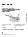 1
1
-
 2
2
-
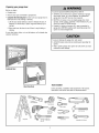 3
3
-
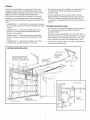 4
4
-
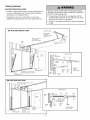 5
5
-
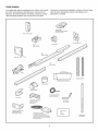 6
6
-
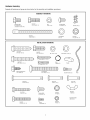 7
7
-
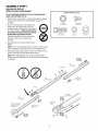 8
8
-
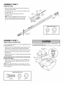 9
9
-
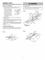 10
10
-
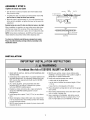 11
11
-
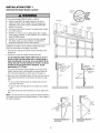 12
12
-
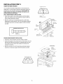 13
13
-
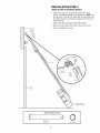 14
14
-
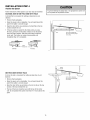 15
15
-
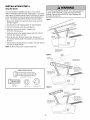 16
16
-
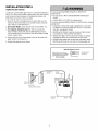 17
17
-
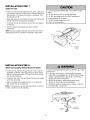 18
18
-
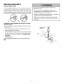 19
19
-
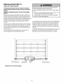 20
20
-
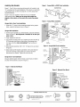 21
21
-
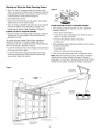 22
22
-
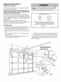 23
23
-
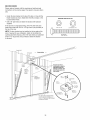 24
24
-
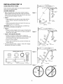 25
25
-
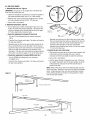 26
26
-
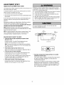 27
27
-
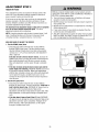 28
28
-
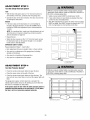 29
29
-
 30
30
-
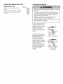 31
31
-
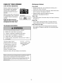 32
32
-
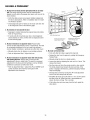 33
33
-
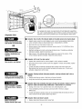 34
34
-
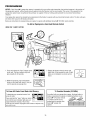 35
35
-
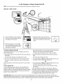 36
36
-
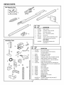 37
37
-
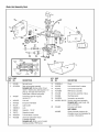 38
38
-
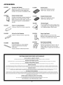 39
39
-
 40
40
-
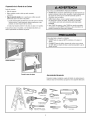 41
41
-
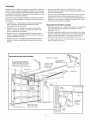 42
42
-
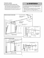 43
43
-
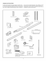 44
44
-
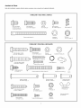 45
45
-
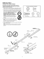 46
46
-
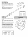 47
47
-
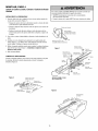 48
48
-
 49
49
-
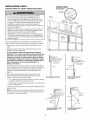 50
50
-
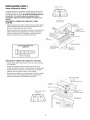 51
51
-
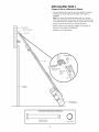 52
52
-
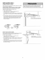 53
53
-
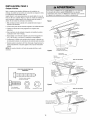 54
54
-
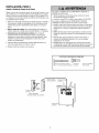 55
55
-
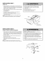 56
56
-
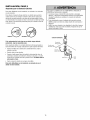 57
57
-
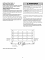 58
58
-
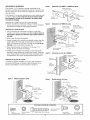 59
59
-
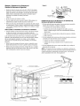 60
60
-
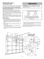 61
61
-
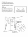 62
62
-
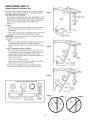 63
63
-
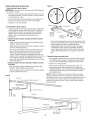 64
64
-
 65
65
-
 66
66
-
 67
67
-
 68
68
-
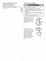 69
69
-
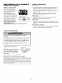 70
70
-
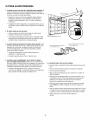 71
71
-
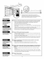 72
72
-
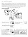 73
73
-
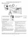 74
74
-
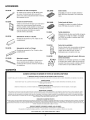 75
75
-
 76
76


Craftsman 139536481DM El manual del propietario
- Categoría
- Abridor de puerta de garage
- Tipo
- El manual del propietario
en otros idiomas
- English: Craftsman 139536481DM Owner's manual
Artículos relacionados
-
Craftsman 13953648D El manual del propietario
-
-
-
-
-
Craftsman 13953915D El manual del propietario
-
-
-
-