Merik 790LMK El manual del propietario
- Categoría
- Abridor de puerta de garage
- Tipo
- El manual del propietario

GARAGE DOOR OPENER
Model 790LMK
For Residential Use Only
OWNER’S MANUAL
■ Please read this manual and the enclosed safety materials carefully!
■ Fasten the manual near the garage door after installation.
■ Periodic checks of the opener are required to ensure safe operation.
■ The model number label is located on the front panel of your opener.
®
New!
Optional Accessory
Available
See Page 39 for the New
Battery Backup
System

2
Introduction 2-8
Safety symbol and signal word review . . . . . . . . . . . . . . . . . . . . 2
Preparing your garage door . . . . . . . . . . . . . . . . . . . . . . . . . . . . 3
Tools needed. . . . . . . . . . . . . . . . . . . . . . . . . . . . . . . . . . . . . . . . 3
Planning . . . . . . . . . . . . . . . . . . . . . . . . . . . . . . . . . . . . . . . . . .4-6
Carton inventory . . . . . . . . . . . . . . . . . . . . . . . . . . . . . . . . . . . . . 7
Hardware inventory. . . . . . . . . . . . . . . . . . . . . . . . . . . . . . . . . . . 8
Assembly 9-15
Assemble rail & attach the pulley bracket . . . . . . . . . . . . . . . .9-10
Install the trolley . . . . . . . . . . . . . . . . . . . . . . . . . . . . . . . . . . . . 11
Fasten the rail to the motor unit . . . . . . . . . . . . . . . . . . . . . . . . 12
Install the chain and sprocket cover . . . . . . . . . . . . . . . . . . .13-14
Tighten the chain . . . . . . . . . . . . . . . . . . . . . . . . . . . . . . . . . . . 15
Installation 15-28
Installation safety instructions . . . . . . . . . . . . . . . . . . . . . . . . . 15
Determine the header bracket location . . . . . . . . . . . . . . . . .16-17
Install the header bracket . . . . . . . . . . . . . . . . . . . . . . . . . . . . . 18
Attach the rail to the header bracket . . . . . . . . . . . . . . . . . . . . . 19
Position the opener. . . . . . . . . . . . . . . . . . . . . . . . . . . . . . . . . . 20
Hang the opener . . . . . . . . . . . . . . . . . . . . . . . . . . . . . . . . . . . . 21
Install the door control . . . . . . . . . . . . . . . . . . . . . . . . . . . . . . . 22
Install the lights . . . . . . . . . . . . . . . . . . . . . . . . . . . . . . . . . . . . 23
Attach the emergency release rope and handle. . . . . . . . . . . . . 23
Electrical requirements . . . . . . . . . . . . . . . . . . . . . . . . . . . . . . . 24
Fasten the door bracket. . . . . . . . . . . . . . . . . . . . . . . . . . . . .25-26
Connect the door arm to the trolley . . . . . . . . . . . . . . . . . . .27-28
Adjustment 29-31
Program the travel limits. . . . . . . . . . . . . . . . . . . . . . . . . . . . . . 29
Set the force . . . . . . . . . . . . . . . . . . . . . . . . . . . . . . . . . . . . . . . 30
Test the safety reversal system. . . . . . . . . . . . . . . . . . . . . . . . . 31
Operation 32-35
Operation safety instructions . . . . . . . . . . . . . . . . . . . . . . . . . . 32
Using your garage door opener . . . . . . . . . . . . . . . . . . . . . . . . 32
Using the wall-mounted door control . . . . . . . . . . . . . . . . . . . . 33
To open the door manually . . . . . . . . . . . . . . . . . . . . . . . . . . . . 33
Care of your garage door opener . . . . . . . . . . . . . . . . . . . . . . . 34
Having a problem? . . . . . . . . . . . . . . . . . . . . . . . . . . . . . . . .34-35
Programming 36-37
To add or reprogram a hand-held remote control. . . . . . . . . . . 36
To erase all codes . . . . . . . . . . . . . . . . . . . . . . . . . . . . . . . . . . . 36
3-button remote controls . . . . . . . . . . . . . . . . . . . . . . . . . . . . . 36
To add, reprogram or change a Keyless Entry PIN . . . . . . . . . . 37
Repair Parts 38
Accessories 39
Service Numbers 40
Warranty 40
TABLE OF CONTENTS
When you see these Safety Symbols and Signal Words on the
following pages, they will alert you to the possibility of
serious injury or death if you do not comply with the warnings
that accompany them. The hazard may come from something
mechanical or from electric shock. Read the warnings carefully.
When you see this Signal Word on the following pages, it will
alert you to the possibility of damage to your garage door and/or
the garage door opener if you do not comply with the cautionary
statements that accompany it. Read them carefully.
Mechanical
Electrical
INTRODUCTION
Safety Symbol and Signal Word Review
This garage door opener has been designed and tested to offer safe service provided it is installed, operated, maintained and tested in
strict accordance with the instructions and warnings contained in this manual.

3
Pliers
Wire Cutters
Claw Hammer
Hack Saw
Screwdriver
Adjustable End Wrench
1/2" and 7/16" Sockets
and Wrench
Drill
Tape Measure
2
1
Stepladder
Pencil
3/16", 5/16" and
5/32" Drill Bits
Carpenter’s
Level (Optional)
Preparing your garage door
Before you begin:
• Disable locks.
• Remove any ropes connected to garage door.
• Complete the following test to make sure your garage door is
balanced and is not sticking or binding:
1. Lift the door about halfway as shown. Release the door. If
balanced, it should stay in place, supported entirely by its
springs.
2. Raise and lower the door to see if there is any binding or
sticking.
If your door binds, sticks, or is out of balance, call a trained door
systems technician.
Tools needed
During assembly, installation and adjustment of the opener,
instructions will call for hand tools as illustrated below.
To prevent damage to garage door and opener:
• ALWAYS disable locks BEFORE installing and operating the
opener.
• ONLY operate garage door opener at 120V, 60 Hz to avoid
malfunction and damage.
To prevent possible SERIOUS INJURY or DEATH:
• ALWAYS call a trained door systems technician if garage
door binds, sticks, or is out of balance. An unbalanced
garage door may NOT reverse when required.
• NEVER try to loosen, move or adjust garage door, door
springs, cables, pulleys, brackets or their hardware, ALL of
which are under EXTREME tension.
• Disable ALL locks and remove ALL ropes connected to
garage door BEFORE installing and operating garage door
opener to avoid entanglement.
Sectional Door
One-Piece Door

4
Safety Reversing Sensor
(Optional Accessory)
Support bracket &
fastening hardware
is required.
See page 21.
— — — — — — — —
Header Wall
FINISHED CEILING
Torsion
Spring
Extension
Spring
OR
Safety Reversing Sensor
(Optional Accessory)
Gap between floor
and bottom of door
must not exceed 6 mm.
Access
Door
Wall-mounted
Door Control
Horizontal and vertical reinforcement
is needed for lightweight garage doors
(fiberglass, steel, aluminum, door with
glass panels, etc.). See page 25 for details.
Motor unit
Slack in chain tension
is normal when
garage door is closed
Vertical
Centerline of
Garage Door
SECTIONAL DOOR INSTALLATION
Planning
Identify the type and height of your garage door. Survey your
garage area to see if any of the conditions below apply to your
installation. Additional materials may be required. You may
fi nd it helpful to refer back to this page and the accompanying
illustrations as you proceed with the installation of your opener.
Depending on your requirements, there are several installation
steps which may call for materials or hardware not included in the
carton.
• Installation Step 1 – Look at the wall or ceiling above the
garage door. The header bracket must be securely fastened to
structural supports.
• Installation Step 5 – Do you have a fi nished ceiling in your
garage? If so, a support bracket and additional fastening
hardware may be required.
• Do you have an access door in addition to the garage door?
If not, Model 1702E Outside Quick Release is required. See
Accessories page.
• Look at the garage door where it meets the fl oor. Any gap
between the fl oor and the bottom of the door must not exceed
6 mm. Otherwise, the safety reversal system may not work
properly. See Adjustment Step 3. Floor or door should be
repaired.
SECTIONAL DOOR INSTALLATIONS
• Do you have a steel, aluminum, fi berglass or glass panel
door? If so, horizontal and vertical reinforce ment is required
(Installation Step 10).
• The opener should be installed above the center of the door. If
there is a torsion spring or center bearing plate in the way of
the header bracket, it may be installed within 1.2 m to the left or
right of the door center. See Installation Steps 1 and 10.
Cable Pulley
Bracket
Header
Bracket
Trolley
Straight
Door
Arm
Emergency
Release
Rope & Handle
Door Bracket
Garage
Door
Curved
Door
Arm
Garage
Door
Spring
Header
Wall
CLOSED POSITION
T-rail
Chain
Chain Sprocket
Bracket
CLOSED POSITION
Header
Bracket
Trolley
T-rail
Chain
Emergency Release
Rope & Handle
Straight
Door
Arm
Curved
Door
Arm
Door Bracket
Header
Wall
Garage
Door
Spring
Garage
Door

5
Planning (Continued)
ONE-PIECE DOOR INSTALLATIONS
• Generally, a one-piece door does not require reinforcement.
If your door is lightweight, refer to the information relating to
sectional doors in Installation, Step 10.
• Depending on your door’s construction, you may need
additional mounting hardware for the door bracket (Step 10).
Without a properly working safety reversal system, persons
(particularly small children) could be SERIOUSLY INJURED or
KILLED by a closing garage door.
• The gap between the bottom of the garage door and the fl oor
MUST NOT exceed 6 mm. Otherwise, the safety reversal
system may NOT work properly.
• The fl oor or the garage door must be repaired to eliminate
the gap.
Safety
Reversing Sensor
(Optional accessory)
FINISHED CEILING
Support bracket
& fastening
hardware is required.
See page 21.
Slack in chain tension
is normal when
garage door is closed
Safety
Reversing Sensor
(Optional accessory)
Header
Wall
Access
Door
Gap between floor and bottom
of door must not exceed 6 mm.
Motor Unit
Wall-mounted
Door Control
ONE-PIECE DOOR WITHOUT TRACK
CLOSED POSITION
Cable
Pulley Bracket
Header
Bracket
Trolley
Straight
Door
Arm
Emergency
Release
Rope & Handle
Door
Bracket
Curved
Door
Arm
Header
Wall
Rail
Garage
Door
Chain Sprocket
Bracket
Access
Door
Trolley
Header
Bracket
Door
Bracket
Header
Wall
Garage
Door
Straight
Door
Arm
Curved
Door
Arm
Emergency
Release
Rope & Handle
T-Rail
CLOSED POSITION
CLOSED POSITION
Access
Door
Gap between floor
and bottom of door
must not exceed 6 mm.
Safety Reversing
Sensor
Wall-
Mounted
Door
Control
Cable
Pulley Bracket
Door
Bracket
Straight
Door
Arm
Trolley
Header
Wall
Rail
Garage
Door
Emergency Release
Rope & Handle
Chain
Header
Bracket
Curved
Door Arm
Safety Reversing
Sensor
(Optional Accessory)
(Optional Accessory)
ONE-PIECE DOOR WITH TRACK
Trolley
Emergency Release Rope
& Handle
Chain
T-rail
Header
Bracket
Door
Bracket
Header
Wall
Access
Door
Wall-
Mounted
Door
Control
Garage
Door
Straight
Door
Arm
Curved
Door Arm
Chain Sprocket
Bracket
Gap between floor and
bottom of door must not
exceed 6 mm.
Safety
Reversing Sensor
(Optional Accessory)
Safety Reversing
Sensor
(Optional Accessory)
CLOSED POSITION

6
The Chamberlain Group, Inc.
Sliding Gate Opener
Completed Installation
9/19/92 - 9/30/92
Safety Reversing Sensor
(Optional accessory)
Safety Reversing Sensor
(Optional accessory)
Header Wall
Safety Reversing Sensor
(Optional accessory)
Safety Reversing Sensor
(Optional accessory)
SLIDING GATE INSTALLATION
SWINGING GATE INSTALLATION
Planning (Continued)
GATE INSTALLATIONS
• It is recommended that you attach fi ne mesh or screening
across the inside of swinging or sliding gates in order to
prevent intruders from reaching through the bars and releasing
the trolley from the door arm or pressing the door control
button.
• The opener must be protected from rain and/or moisture.
Without a properly working safety reversal system, persons
(particularly small children) could be SERIOUSLY INJURED or
KILLED by a closing gate.
• Activate gate ONLY when the gate is in full view and free
from any obstructions.
• ALWAYS keep gate in sight until completely closed. NEVER
permit anyone to cross the path of the moving gate.
• ALWAYS keep gate in good repair and make sure it moves
freely. An improperly maintained gate may NOT reverse when
required and could result in SEVERE PERSONAL INJURY or
DEATH.
Safety Reversing Sensor
(Optional accessory)
Safety Reversing Sensor
(Optional accessory)
Safety Reversing Sensor
(Optional accessory)
Header Wall
Safety Reversing Sensor
(Optional accessory)

7
41A2780
Cable Sprocket Bracket
41B4494-1
2-Conductor Bell Wire
White & White/Red
41A3489
Trolley
41A4353-1
Header Bracket
41A3611-2
Chain Dispensing Carton
178B35
Curved Door
Arm Section
178B34
Straight Door
Arm Section
Safety Labels
and
Literature
12B776
Hanging Brackets
UP
CEILING MOUNT ONLY
41A5047-1
Door Bracket
41A5273-21
Multi-Function
Door Control Panel
LOCK
LIGHT
1B3117
Rail Center Section
TO GARAGE DOOR
183B110
Rail End Section (each)
SECURITY
®
Multi-Function Remote Control (2)
Motor Unit and Light Lens
(Light Lens Part Number: 108D78)
41A4371-2
Sprocket Cover
29B137
Remote Control
Transmitter Visor Clip
83A11-2
Rail Grease
Your garage door opener is packaged in two cartons which
contains the motor unit and the parts illustrated below. Note that
accessories will depend on the model purchased. If anything is
missing, carefully check the packing material.
Parts may be stuck in the foam. Hardware for assembly and
installation is shown on the next page. Save the carton and
packing material until installation and adjustment is complete.
Carton Inventory
Chain Pulley
Bracket
41A2780
41A2780
Chain Sprocket Bracket
41A273-21LMK
Multi-Function
Door Control Panel
973LMK
SECURITY✚
®
Multi-Function Remote Control (2)

8
Hardware Inventory
Separate all hardware and group as shown below for the assembly and installation procedures.
Hex Bolt
5/16"-18x7/8" (4)
Screw
6-32x1" (2)
Screw
6ABx1-1/4" (2)
Lock Washer
5/16" (4)
Nut
5/16"-18 (4)
Clevis Pin
5/16"x2-3/4" (1)
NOTICE
Handle
Insulated
Staples (10)
Drywall Anchors (2)
Clevis Pin
5/16"x1" (1)
Rope
Lock Nut
1/4"-20x7/16" (4)
Nut
5/16"-18 (5)
Washered Screw
5/16"-18x1/2" (2)
(mounted in opener)
Carriage Bolt
1/4"-20x1/2" (4)
Hex Bolt
5/16"-18x7/8" (3)
Master Link (2)
Ring Fastener (3)
Trolley
Threaded Shaft (1)
Lock Washer
5/16" (4)
Clevis Pin
5/16"x1-1/4" (1)
Lag Screw
5/16"-9x1-5/8" (2)
Lag Screw
5/16"-9x1-7/8" (2)
Self-Threading Screw
1/4"-14x5/8" (2)
Installation Hardware 41A3475-30
Assembly Hardware

9
ASSEMBLY STEP 1
For Sectional and One-Piece Doors ONLY
Assemble the T-Rail and Attach the Chain
Sprocket Bracket
To avoid installation difficulties, do not run the garage door
opener until instructed to do so.
1. Place the 3 T-rail sections on a fl at surface for assembly.
The end sections are identical. The center section must
be positioned with the braces against the
end sections as shown. Make sure the
“directional arrow” on the center section is
pointing toward the front (to door). Study the
illustration carefully.
2. Bolt rail sections together with the hardware
illustrated and from the direction indicated.
(When assembled, T-rail has a front-to-back
position as shown.)
NOTE: If T-rail is not assembled exactly as
shown, trolley will not travel smoothly along
length of rail or it will hit against nuts.
3. Position the chain sprocket bracket on the front end of the
T-rail as shown. Fasten securely with the hardware provided.
NOTE: When tightening the bolts be sure to keep bracket
parallel to the rail. Otherwise, the rail may bow when the
opener is operated.
HARDWARE
SHOWN ACTUAL SIZE
11 mm Socket Wrench
13 mm Socket Wrench
Lock Nut
1/4"-20
Carriage Bolts
1/4"-20x1/2"
Hex Bolt
5/16"-18x7/8"
Nut
5/16"-18
Lock Washer
5/16"
Hex Bolts
5/16"-18x7/8"
Rail Bracket & Rail Must Be
Aligned
Lock Washer
5/16"
Nut
5/16"
Chain Pulley
Bracket
Chain Sprocket
Bracket
Lock Washer
5/16"
Nut
5/16"
Rail Bracket & Rail Must Be Aligned
Hex Bolts
5/16"-18x7/8"
Rail
(Center Section)
1/4'' Lock Nut
RAIL FRONT
(TO DOOR)
Cable pulley bracket
attaches to FRONT
END of Rail
Rail
(End Section)
RAIL BACK
(TO OPENER)
Rail
(End Section)
Carriage Bolt
1/4"-20x1/2"
Brace
Brace
Square Carriage
Bolt Holes
OT G
RAGA D E OOR
Hex Bolts
5/16"-18x7/8"
dengilA eB tsuM lia
& tekcarB liaR
Lock Washer
5/16"
Nut
5/16"
Cable Pulley
Bracket
R
Chain Sprocket Bracket
attaches to FRONT END
of Rail
RAIL BACK
(TO OPENER)
Rail
(End Section)
1/4" Lock Nut
Carriage Bolt
1/4"-20x1/2"
Rail
(Center Section)
Brace
RAIL FRONT
(TO DOOR)
Rail
(End Section)
Brace
Square Carriage
Bolt Holes

10
ASSEMBLY STEP 1
For Sliding and Swinging Gates ONLY Assemble the
T-Rail and Attach the Chain Sprocket Bracket
To avoid installation difficulties, do not run the garage door
opener until instructed to do so.
1. Place the 3 T-rail sections on a fl at surface
for assembly. The end sections are identical.
Make sure the “arrow label” on the center
section is pointing in the direction shown in the
illustration.
2. Connect the center section and the 1/4" lock
nuts to the end sections from the same side, as
shown.
NOTE: If T-rail is not assembled exactly as
shown, trolley will not travel smoothly along
length of rail or it will hit against nuts.
3. Insert the carriage bolts from the opposite side of the end
sections. Tighten the nuts. When assembled, T-rail has a
front-to-back position as shown.
4. Position the chain sprocket bracket on the front end of the
T-rail as shown. Fasten securely with the hardware provided.
NOTE: When tightening the bolts be sure to keep bracket
parallel to the rail. Otherwise, the rail may bow when the
opener is operated.
Rail
(Center Section)
1/4'' Lock Nut
Cable pulley bracket
attaches to this
end of rail.
Rail
(End Section)
Carriage Bolt
1/4"-20x1/2"
Brace
Square Carriage
Bolt Holes
ROOD EGARAG OT
AWAY FROM
OPENER
Brace
Rail
(End Section)
Rail connects to
opener at this end.
Tuerca de 1/4"
Riel en "T"
(Sección Extrema)
El sostén de la polea
del cable se fija a este
extremo del riel en "T".
Hex Bolts
5/16"-18x7/8"
Cable Pulley
Bracket
dengilA eB tsuM lia
& tekcarB liaR
Lock Washer
5/16"
Nut
5/16"
R
Chain sprocket bracket
attaches to this end
of Rail
AWAY FROM
OPENER
Rail connects to
opener at this end.
Carriage Bolt
1/4"-20x1/2"
Rail
(End Section)
Rail
(End Section)
Rail
(Center Section)
Square Carriage
Bolt Holes
1/4" Lock Nut
Brace
Brace
13 mm Socket Wrench
11 mm Socket Wrench
Lock Nut
1/4"-20
Carriage Bolts
1/4"-20x1/2"
Hex Bolt
5/16"-18x7/8"
Nut
5/16"-18
Lock Washer
5/16"
HARDWARE
SHOWN ACTUAL SIZE
Carriage Bolts
1/4"-20x1/2"
Lock Washer
5/16"
Hex Bolt
5/16"-18x7/8"
Lock Nut
1/4"-20
Nut
5/16"-18
Hex Bolts
5/16"-18x7/8"
Chain Pulley
Bracket
Rail Bracket &
Rail Must Be A
ligne
d
Lock Washer
5/16"
Nut
5/16"
Chain Sprocket
Bracket
Lock Washer
5/16"
Nut
5/16"
Rail Bracket & Rail Must Be Aligned
Hex Bolts
5/16"-18x7/8"

11
ASSEMBLY STEP 2
For Sectional and One-Piece Doors Only Install the
Trolley
• Attach the trolley threaded shaft to the trolley with the lock
washer and nuts as shown.
• As a temporary stop, insert a screwdriver into the hole in the
front end of the T-rail.
• Slide the trolley assembly along the rail to the screwdriver stop.
NOTE: If trolley hits against any nuts on the rail, the bolts
and nuts were attached from the wrong side and must be
repositioned. Review Assembly Step 1.
ASSEMBLY STEP 2
For Sliding and Swinging Gates Only
Install the Trolley
• Attach the trolley threaded shaft to the trolley with the lock
washer and nuts as shown.
• Insert a hex bolt into the hole in the front end of the T-rail.
• Slide the trolley assembly along the rail until it rests against the
hex bolt (trolley stop).
NOTE: If trolley hits against any nuts on the rail, the bolts
and nuts were attached from the wrong side and must be
repositioned. Review Assembly Step 1.
Trolley
Threaded
Shaft
Lock Washer
5/16"
Outer Nut
5/16"
Inner Nut
5/16"
Trolley
Temporary Stop
Screwdriver
TO G
A
RA
GED
OOR
Outer Nut
5/16"-18
Inner Nut
5/16"-18
Trolley
Threaded
Shaft
Temporary Stop
Screwdriver
Trolley
Lock Washer
5/16"
Lock Washer
5/16"
Nut
5/16"-18
HARDWARE SHOWN ACTUAL SIZE
Nut
5/16"-18
Lock Washer
5/16"
Nut
5/16"-18
Lockwasher
5/16"
Hex Bolt
5/16"-18x7/8"
HARDWARE SHOWN ACTUAL SIZE
Hex Bolt
5/16"-18x7/8"
Nut 5/16"-18
Lock Washer
5/16"
Outer Nut
5/16"
Trolley
Threaded
Shaft
Lock Washer
5/16"
Inner Nut
5/16"
ROODE
GAR
A
G
O
T
Hex Bolt
Trolley Stop
Hex Bolt
5/16"-18x7/8"
Nut
5/16"-18
Lock Washer
5/16"
Chain Pulley
Bracket
Chain Sprocket
Bracket
Trolley
Threaded
Shaft
Hex Bolt
5/16"-18x7/8"
Hex Bolt
Trolley Stop
Lock Washer
5/16"
Lock Washer
5/16"
Lock Washer
5/16"
Inner Nut
5/16"-18
Inner Nut
5/16"-18
Outer Nut
5/16"-18

12
ASSEMBLY STEP 3
Fasten the Rail to the Motor Unit
• Place the opener on packing material to protect the cover. For
convenience, put a support under the cable pulley bracket.
• Remove the two 5/16"-18x1/2" washered bolts mounted in the
top of the motor unit.
• Align the holes in the back section of the T-rail with the holes in
the motor unit.
• Fasten the rail with the two washered bolts previously removed.
Tighten securely. Remember to use only these bolts! Any
other bolts will cause serious damage to the opener.
• Insert a 5/16"-18x7/8" hex bolt into the cover protection bolt
hole in the rail as shown. Tighten securely with a 5/16" lock
washer and nut.
NOTE: This bolt prevents trolley over-travel. Keep a 25 mm
minimum between the trolley and this bolt when adjusting travel
limits (see page 29).
Washered Bolt
5/16"-18x1/2"
Rail
(Back
Section)
Cover
Protection
Bolt Hole
Nut
5/16"-18
Hex Bolt
5/16"-18x7/8"
Lock Washer
5/16"
USE ONLY THIS
TYPE AND SIZE BOLT
To avoid SERIOUS damage to garage door opener, use ONLY
those bolts/fasteners mounted in the top of the opener.
Nut
5/16"-18
Lock Washer
5/16"
Hex Bolt
5/16"-18x7/8"
HARDWARE SHOWN ACTUAL SIZE
Hex Bolt
5/16"-18x7/8"
Nut
5/16"-18
Lock Washer
5/16"

13
ASSEMBLY STEP 4
For Sectional and One-Piece Doors Only
Install the Chain
1. Dispense a few inches of chain
from carton and fasten to
trolley with a master link from
the hardware bag (Figure 1).
• Push pins of master link bar
through chain link and hole
in front end of trolley.
• Push master link cap over
pins and past pin notches.
• Slide clip-on spring over cap and onto pin notches until both
pins are securely locked in place.
2. With the trolley against the screwdriver, dispense the chain
around the chain sprocket bracket.
3. Continue along the rail and around the motor unit sprocket
(Figure 2). Proceed back around the correct groove in the chain
spreader (Figure 3). The sprocket teeth must engage the chain.
4. Use the second master link to connect the chain to the fl at end
of the shaft (Figure 1). Check to make sure the chain is not
twisted.
5. Remove the screwdriver.
ATTACHING THE SPROCKET COVER
Position the sprocket cover over the motor unit sprocket so the
three holes in cover align with the three holes in mounting plate.
Attach with #8x3/8" hex screws provided (Figure 3).
To avoid possible SERIOUS INJURY to fi ngers from moving
garage door opener:
• ALWAYS keep hand clear of sprocket while operating opener.
• Securely attach sprocket cover BEFORE operating.
Motor Unit
Sprocket
Install Chain
In This Direction
Figure 2
Mounting
Plate
Sprocket
Hex Screws
#8x3/8"
Figure 3
Mantenga la cadena
tensa al sacarla
No saque la
cadena de la
caja para evitar
que se tuerce
Leave Chain
Inside Carton
to Prevent
Kinking
Keep Chain Taut
When Dispensing
Master
Link Bar
Flat End
of Trolley
Trolley
Pin
Pin Notch
Flat End of
Threaded Shaft
Master Link
Clip-On Spring
Master
Link Cap
Install Chain
In This Direction
Chain
Pulley
Bracket
Figure 1
Master
Link Bar
Flat End
of Trolley
Pin
Pin Notch
Flat End of Trolley
Threaded Shaft
Chain
Sprocket
Bracket
Install Chain
In This Direction
Trolley
Master Link
Clip-On Spring
Hex Screws
#8x3/8"
Motor Unit
Sprocket
Install the Chain in
This Direction
Sprocket
Mounting
Plate
Master
Link Cap

14
To avoid possible SERIOUS INJURY to fi ngers from moving
opener:
• ALWAYS keep hand clear of sprocket while operating opener.
• Securely attach sprocket cover BEFORE operating.
Mounting
Plate
Chain Link
Master
Link
Pin
Master Link
Clip-On Spring
Flat End
of Trolley
Trolley
Pin Notch
Flat End of
Threaded Shaft
Master
Link Cap
Master Link
Clip-On Spring
Master
Link Cap
Chain Link
5-15 cm
Master
Link
Pin
Pin Notch
Rail
Chain
Sprocket
Install Chain
in this Direction.
ATTACHING THE SPROCKET COVER
Position the sprocket cover over the motor unit sprocket so the
three holes in cover align with the three holes in mounting plate.
Attach with #8x3/8" hex screws provided.
Figure 1
ASSEMBLY STEP 4
For Sliding and Swinging Gates Only Install the Chain
1. Dispense a few inches of chain
from carton and fasten to trolley
with a master link from the
hardware bag. (Figure 1).
• Push pins of master link bar
through chain link and hole in
front end of trolley.
• Push master link cap over pins
and past pin notches.
• Slide clip-on spring over cap and onto pin notches until both
pins are securely locked in place.
2. To prevent the trolley from jamming against the opener during
operation, position trolley 5 to 15 cm from the stop hole as
shown. Then dispense the chain around the opener sprocket
(Figure 1). Make sure the sprocket teeth engage the chain.
• Proceed around to the chain sprocket bracket and forward to
the threaded trolley shaft.
3. Use the second master link to connect the chain to the flat end
of the shaft (Figure 1). Check to make sure the chain is not
twisted.
Mantenga la cadena
tensa al sacarla
No saque la
cadena de la
caja para evitar
que se tuerce
Leave Chain
Inside Carton to
Prevent Kinking
Keep Chain Taut
When Dispensing

15
ASSEMBLY STEP 5
Tighten the Chain
• Spin the inner nut and lock washer down the trolley threaded
shaft, away from the trolley.
• To tighten the chain, turn outer nut in the direction shown.
AS YOU TURN THE NUT, KEEP THE CHAIN FROM TWISTING.
• When the chain is approximately 13 mm above the base of
the rail at its midpoint, re-tighten the inner nut to secure the
adjustment.
Sprocket noise can result if chain is either too loose or too
tight.
NOTE: When installation is complete, you may notice some chain
droop with the door closed. This is normal. If the chain returns to
the position shown when the door is open, do not re-adjust the
chain.
NOTE: During future maintenance, ALWAYS pull the emergency
release handle to disconnect trolley before adjusting chain.
You have now finished assembling your garage door opener.
Please read the following warnings before proceeding to the
installation section.
INSTALLATION
Lock
Washer
To Tighten Outer Nut
Inner Nut
Chain
Base of Rail
13 mm
To Tighten
Inner Nut
Outer Nut
Outer Nut
Chain
13 mm
Base of Rail
To Tighten Outer Nut
To Tighten
Inner Nut
Inner Nut
Lock
Washer
15
IMPORTANT INSTALLATION INSTRUCTIONS
To reduce the risk of SEVERE INJURY or DEATH:
WARNING
WARNING
WARNING WARNING
1. READ AND FOLLOW ALL INSTALLATION WARNINGS AND
INSTRUCTIONS.
2. Install garage door opener ONLY on properly balanced and
lubricated garage door. An improperly balanced door may
NOT reverse when required and could result in SEVERE
INJURY or DEATH.
3. ALL repairs to cables, spring assemblies and other hardware
MUST be made by a trained door systems technician BEFORE
installing opener.
4. Disable ALL locks and remove ALL ropes connected to garage
door BEFORE installing opener to avoid entanglement.
5. Install garage door opener 7 feet (2.13 m) or more above
fl oor.
6. Mount the emergency release within reach, but at least 6 feet
(1.8 m) above the fl oor and avoiding contact with vehicles to
avoid accidental release.
7. NEVER connect garage door opener to power source until
instructed to do so.
8. NEVER wear watches, rings or loose clothing while installing
or servicing opener. They could be caught in garage door or
opener mechanisms.
9. Install wall-mounted garage door control:
• within sight of the garage door.
• out of reach of children at minimum height of
5 feet (1.5 m).
• away from ALL moving parts of the door.
10. Place entrapment warning label on wall next to garage door
control.
11. Place manual release/safety reverse test label in plain view
on inside of garage door.
12. Upon completion of installation, test safety reversal system.
Door MUST reverse on contact with a 1-1/2" (3.8 cm) high
object (or a 2x4 laid fl at) on the fl oor.

16
Unfinished
Ceiling
38 mm
OPTIONAL
CEILING
MOUNT
FOR
HEADER
BRACKET
Header Wall
38 mm
Structural
Supports
Vertical Centerline
of Garage Door
Level
(optional)
INSTALLATION STEP 1
Determine the Header Bracket Location
Installation procedures vary according to garage door types.
Follow the instructions which apply to your door.
If your door is a canopy or dual-track style garage door, a
door arm conversion kit is REQUIRED. Follow the installation
instructions included with the replacement door arm sectional.
SECTIONAL DOOR AND ONE-PIECE DOOR WITH TRACK
1. Close the door and mark the inside vertical centerline of the
garage door.
2. Extend the line onto the header wall above the door.
You can fasten the header bracket within 1.2 m of the left
or right of the door center only if a torsion spring or center
bearing plate is in the way; or you can attach it to the
ceiling (see page 18) when clearance is minimal. (It may
be mounted on the wall upside down if necessary, to gain
approximately 1 cm.)
If you need to install the header bracket on a 38 mm board
(on wall or ceiling), use lag screws (not provided) to securely
fasten the 38 mm board to structural supports as shown here
and on page 17.
3. Open your door to the highest point of travel as shown. Draw
an inter secting horizontal line on the header wall 5 cm above
the high point. This height will provide travel clearance for the
top edge of the door.
Proceed to Step 2, page 18.
To prevent possible SERIOUS INJURY or DEATH:
• Header bracket MUST be RIGIDLY fastened to structural
support on header wall or ceiling, otherwise garage door
might NOT reverse when required. DO NOT install header
bracket over drywall.
• Concrete anchors MUST be used if mounting header bracket
or 38 mm board into masonry.
• NEVER try to loosen, move or adjust garage door, springs,
cables, pulleys, brackets, or their hardware, ALL of which are
under extreme tension.
• ALWAYS call a trained door systems technician if garage
door binds, sticks, or is out of balance. An unbalanced
garage door might NOT reverse when required.
Header
Wall
Ceiling
SECTIONAL DOOR
WITH CURVED TRACK
Track
Highest Point
of Travel
Door
Header
Wall
Door
Track
Jamb
Hardware
Highest Point
of Travel
ONE-PIECE DOOR
WITH HORIZONTAL
TRACK & JAMB
HARDWARE
Highest Point
of Travel
Door
Track
Garage
Exterior
Track
Header
Wall
Highest Point
of Travel
Door
Track
CANOPY ONE-PIECE
DOOR WITH
VERTICAL TRACK
Header
Wall
ONE-PIECE DOOR
WITH HORIZONTAL &
VERTICAL TRACK
Ceiling
Header
Wall
Header
Wall
Header
Wall
Header
Wall
Highest Point
of Travel
Highest Point
of Travel
Garage
Exterior
Highest Point
of Travel
Highest Point
of Travel
Track
Track
Track
Track
Track
Door
Door
Door
Door
SECTIONAL DOOR
WITH CURVED TRACK
CANOPY ONE-PIECE
DOOR WITH
VERTICAL TRACK
ONE-PIECE DOOR
WITH HORIZONTAL
TRACK & JAMB
HARDWARE
ONE-PIECE DOOR
WITH HORIZONTAL &
VERTICAL TRACK
Jamb
Hardware

17
EXAMPLE
Distance from top of door
(at highest point of travel) to floor ..................................... 234 cm
Actual height of door .........................................................-224 cm
Remainder ........................................................................... 10 cm
Add .................................................................................... +20 cm
Bracket height on header wall ............................................ =30 cm
(Measure UP from top of CLOSED door.
)
Proceed to Step 2, page 18.
ONE-PIECE DOOR WITHOUT TRACK
1. Close the door and mark the inside vertical centerline of your
garage door. Extend the line onto the header wall above door,
as shown.
If headroom clearance is minimal, you can install the header
bracket on the ceiling. See page 18.
If you need to install the header bracket on a 38 mm board
(on wall or ceiling), use lag screws (not provided) to securely
fasten the 38 mm board to structural supports as shown.
2. Open your door to the highest point of travel as shown.
Measure the distance from the top of the door to the fl oor.
Subtract the actual height of the door. Add 20 cm to the
remainder. (See Example.)
3. Close the door and draw an intersecting horizontal line on the
header wall at the determined height.
NOTE: If the total number of centimeters exceeds the height
available in your garage, use the maximum height possible, or
refer to page 18 for ceiling installation.
One-piece door without track:
pivot hardware
One-piece door without track: jamb hardware
Header Wall
Vertical
Centerline
of Garage
Door
2x4
Unfinished
Ceiling
2x4
OPTIONAL
CEILING MOUNT
FOR
HEADER BRACKET
Structural
Supports
Vertical
Centerline
of Garage
Door
Header Wall
Structural
Supports
38 mm
Board
Unfinished
Ceiling
OPTIONAL CEILING
MOUNT FOR
HEADER BRACKET
38 mm Board
Header Wall
Highest Point
of Travel
Door
Floor
Distance
Jamb
Hardware
Highest Point
of Travel
Floor
Door
Jamb
Hardware
Distance
Header Wall
Door
Highest Point
of Travel
Header Wall
Pivot
Distance
Floor
Highest Point
of Travel
Pivot
Floor
Door
Distance
Header Wall

18
INSTALLATION STEP 2
Install the Header Bracket
You can attach the header bracket either to the wall above the
garage door, or to the ceiling. Follow the instructions which will
work best for your particular requirements. Do not install the
header bracket over drywall. If installing into masonry, use
concrete anchors (not provided).
WALL HEADER BRACKET INSTALLATION
• Center the bracket on the vertical centerline with the bottom
edge of the bracket on the horizontal line as shown (with the
arrow pointing toward the ceiling).
• Mark the vertical set of bracket holes (do not use the holes
designated for ceiling mount). Drill 5 mm pilot holes and fasten
the bracket securely to a structural support with the hardware
provided.
HARDWARE SHOWN ACTUAL SIZE
CEILING HEADER BRACKET INSTALLATION
• Extend the vertical centerline onto the ceiling as shown.
• Center the bracket on the vertical mark, no more than 15 cm
from the wall. Make sure the arrow is pointing toward the wall.
The bracket can be mounted fl ush against the ceiling when
clearance is minimal.
• Mark the side holes. Drill 5 mm pilot holes and fasten bracket
securely to a structural support with the hardware provided.
Lag Screws
5/16"x9x1-5/8"
Lag Screws
5/16"-9x1-5/8"
Highest Point of
Garage Door Travel
Vertical
Centerline of
Garage Door
Wall Mounting Holes
Optional
Wall Mounting Holes
Door Spring
Header
Bracket
38 mm
Board
Vertical Centerline
of Garage Door
Ceiling Mounting Holes
Lag Screws
5/16"-9x1-5/8"
Garage Door
Vertical Centerline
of Garage Door
Header Wall
Header
Bracket
15 cm Maximum
Vertical
Centerline of
Garage Door
Door
Spring
Finished Ceiling

19
HARDWARE SHOWN ACTUAL SIZE
Header
Bracket
Header Wall
Garage
Door
T-Rail
Temporary
Support
Chain
Sprocket
Bracket
Clevis Pin
5/16"x2-3/4"
Ring Fastener
Header Bracket
Chain
Sprocket
Bracket
T-rail
INSTALLATION STEP 3
Attach the Rail to the Header Bracket
• Position the opener on the garage fl oor below the header
bracket. Use packing material as a protective base.
NOTE: If the door spring is in the way you’ll need help. Have
someone hold the opener securely on a temporary support to
allow the rail to clear the spring.
• Position the rail bracket against the header bracket.
• Align the bracket holes and join with a clevis pin as shown.
• Insert a ring fastener to secure.
Clevis Pin
5/16"x2-3/4"
Ring Fastener

20
ONE-PIECE DOOR WITHOUT TRACK
• With the door fully open and parallel to the fl oor, measure the
distance from the fl oor to the top of the door.
• Using a stepladder as a support, raise the top of the opener to
this height.
• The top of the door should be level with the top of the motor
unit. Do not position the opener more than 5 cm above this
point.
INSTALLATION STEP 4
Position the Opener
Follow instructions which apply to your door type as illustrated.
SECTIONAL DOOR OR ONE-PIECE DOOR WITH TRACK
A 38 mm board is convenient for setting an ideal
door-to-rail distance.
• Raise the opener onto a stepladder. You will need help at this
point if the ladder is not tall enough.
• Open the door all the way and place a 38 mm board on the top
section beneath the rail.
• If the top section or panel hits the trolley when you raise
the door, pull down on the trolley release arm to disconnect
inner and outer sections. Slide the outer trolley toward
the motor unit. The trolley can remain disconnected until
Installation Step 11 is completed.
Rail
38 mm is used to determine
the correct mounting height
from ceiling.
Door
To prevent damage to garage door, rest garage door opener rail
on 38 mm board placed on top section of door.
Header
Bracket
Top of Door
38 mm is used to determine
the correct mounting height
from ceiling.
Rail
Door
38 mm is used to determine the
correct mounting height from ceiling.
Trolley
Release Arm
ENGAGED
RELEASED
Trolley
Release Arm
RELEASED
ENGAGED
Header
Bracket
Top of Door
38 mm is used to determine the
correct mounting height from ceiling.

21
INSTALLATION STEP 5
Hang the Opener
Three representative installations are shown. Yours may be
different. Hanging brackets should be angled (Figure 1) to provide
rigid support. On fi nished ceilings (Figure 2), attach a sturdy
metal bracket to structural supports before installing the opener.
This bracket and fastening hardware are not provided.
Existing brackets from a previous installation may be fastened
to the sides of the motor unit as in Figures 1 and 2, or to the
mounting tabs as shown in Figure 3. Then continue with step 5
below.
1. Remove from packaging. Measure the distance from each side
of the motor unit to the structural support.
2. Cut both pieces of the hanging bracket to required lengths.
3. Drill 5 mm pilot holes in the structural supports.
4. Attach one end of each bracket to a support with
5/16"-18x1-7/8" lag screws.
5. Fasten the opener to the hanging brackets with
5/16"-18x7/8" hex bolts, lock washers and nuts.
6. Check to make sure the T-rail is centered over the door (or in
line with the header bracket if the bracket is not centered above
the door).
7. Remove the 38 mm board. Operate the door manually. If the
door hits the rail, raise the header bracket.
Measure
Distance
Lag Screws
5/16"- 18x1-7/8"
5/16"-18x7/8"
Hex Bolts
5/16" Lock Washers
5/16"-18 Nuts
Structural
Supports
Bracket
(Not Provided)
Lag Screws
5/16"-18x1-7/8"
(Not Provided)
5/16"-18x7/8" Bolt
5/16" Lock Washer
5/16"-18 Nut
Hidden
Support
5/16"-18x7/8" Bolt
5/16" Lock Washer
5/16"-18 Nut
Existing Brackets
Bracket
(Provided)
Figure 1
Figure 2
Figure 3
To avoid possible SERIOUS INJURY from a falling garage door
opener, fasten it securely to structural supports of the garage.
Concrete anchors MUST be used if installing ANY brackets into
masonry.
13 mm Socket Wrench
Hex Bolt
5/16"-18x7/8"
Nut 5/16"-18
Lock Washer 5/16"
Lag Screw
5/16"-18x1-7/8"
HARDWARE SHOWN ACTUAL SIZE
Lag Screw
5/16"-18x1-7/8"
Hex Bolt
5/16"-18x1-7/8"
Nut 5/16"-18
Lock Washer 5/16"
Preferred range of
bracket placement
Preferred range of
bracket placement
Utilizing existing top mount installation
FINISHED CEILING

22
LOCK
LIG
HT
Slot
REMOVE COVER
INSTALLATION STEP 6
Install the Door Control
Locate door control within sight of the door at a minimum height
of 1.5 m where small children cannot reach, and away from
moving parts of the door and door hardware. The installation
surface must be smooth and fl at. If installing into drywall
(Figure 1), drill 4 mm holes and use anchors provided. For
pre-wired installations (as in new home construction), it may be
mounted to a single gang box (Figure 2).
NOTE: After installation, a green indicator light behind the cover
will indicate proper connection. If not lit, the Lock and Light
features will not function (reverse wires to correct).
1. Strip 11 mm of insulation from one end of bell wire and connect
to the two screw terminals on back of door control by color:
white wire to 2 and white/red wire to the 1 (Figure 3).
2. Remove white cover by gently prying at slot in top of the cover
with a small fl at head screwdriver (Figure 4). Fasten with
6ABx1-1/4"self-tapping screws (drywall installation) or 6-32x1"
machine screws (into gang box) as follows:
• Drill and install bottom screw, allowing 3 mm to protrude
above wall surface.
• Position bottom of door control on screw head and slide
down to secure. Adjust screw for snug fi t.
• Install top screw with care to avoid cracking plastic housing.
Do not overtighten.
• Insert bottom tabs and snap on cover. (To remove cover after
mounting, gently pry at top with paper clip or small fl at head
screwdriver.)
NOTE: The push bar may stick if the door control is not mounted
on a smooth surface. If a click is not heard when pressing the
push bar, loosen the two mounting screws or relocate the door
control to a smoother surface.
3. (Standard installation only) Run bell wire up wall and across
ceiling to motor unit. Use insulated staples to secure wire in
several places. Do not pierce wire with a staple, creating a short
or open circuit.
4. Strip 11 mm of insulation from end of bell wire. Connect bell
wire to the quick-connect terminals as follows: white to white
and white/red to red (Figure 5).
5. Use tacks or staples to permanently attach entrapment warning
label to wall near door control, and manual release/safety
reverse test label in a prominent location on inside of garage
door.
WIRING INSTRUCTIONS FOR ACCESSORIES
The Protector System
®
: To opener terminals: White to White and
Black to Black.
Outside Keylock Accessory connections: To opener terminals:
Red/white to Red and White to White.
Bell Wire
Terminal
Screws
Bottom Mounting Hole
Top Mounting Hole
Drywall Anchors
Insulated
Staples
Screw 6ABx1-1/4"
(standard installation)
Screw 6-32x1"
(pre-wired)
HARDWARE SHOWN ACTUAL SIZE
To Replace
Insert Bottom Tabs First
PRE-WIRED
INSTALLATION
24 Volt
Bell Wire
LOCK
LIGHT
LOCK
LIGHT
To Replace
Insert Bottom Tabs First
STANDARD
INSTALLATION
Single
Gang Box
DOOR CONTROL (BACK)
Figure 5
Figure 3
Figure 1
Figure 2
Figure 4
Red
Black
White
To release or insert wire,
push in tab with
screwdriver tip
Door Control
Connections
11 mm
7/16"
Strip wire 11 mm (7/16")
To prevent possible SERIOUS INJURY or DEATH from
electrocution:
• Be sure power is NOT connected BEFORE installing door
control.
• Connect ONLY to 24 VOLT low voltage wires.
To prevent possible SERIOUS INJURY or DEATH from a closing
garage door:
• Install door control within sight of garage door, out of reach
of children at a minimum height of 1.5 m, and away from ALL
moving parts of door.
• NEVER permit children to operate or play with door control
push buttons or remote control transmitters.
• Activate door ONLY when it can be seen clearly, is properly
adjusted, and there are no obstructions to door travel.
• ALWAYS keep garage door in sight until completely closed.
NEVER permit anyone to cross path of closing garage door.
Slot

23
INSTALLATION STEP 7
Install the Lights
• Press the release tabs on both sides of lens. Gently rotate lens
back and downward until the lens hinge is in the fully open
position. Do not remove the lens.
• Install a 100 watt maximum light bulb in the socket. Light bulb
size should be A19, standard neck only. The light will turn ON
and remain lit for approximately 4-1/2 minutes when power is
connected. Then the light will turn OFF.
• Reverse the procedure to close the lens.
• Use A19, standard neck garage door opener bulb for
replacement.
NOTE: Use only standard light bulbs. The use of short neck or
speciality light bulbs may overheat the endpanel or light socket.
INSTALLATION STEP 8
Attach the Emergency Release Rope and Handle
• Thread one end of the rope through the hole in the top of the
red handle so “NOTICE” reads right side up as shown. Secure
with an overhand knot at least 38 mm from the end of the rope
to prevent slipping.
• Thread the other end of the rope through the hole in the release
arm of the outer trolley.
• Adjust rope length so the handle is 1.8 m above the fl oor.
Secure with an overhand knot.
NOTE: If it is necessary to cut the rope, heat seal the cut end with
a match or lighter to prevent unraveling.
Lens Hinge Slots
Release Tab
Lens Hinge
Lens
Release
Tab Slot
Release Tab
Release
Tab Slot
100 Watt (Max)
Standard Light Bulb
To prevent possible SERIOUS INJURY or DEATH from a falling
garage door:
• If possible, use emergency release handle to disengage trolley
ONLY when garage door is closed. Weak or broken springs or
unbalanced door could result in an open door falling rapidly
and/or unexpectedly.
• NEVER use emergency release handle unless garage doorway
is clear of persons and obstructions.
• NEVER use handle to pull door open or closed. If rope knot
becomes untied, you could fall.
To prevent possible OVERHEATING of the endpanel or light
socket:
• DO NOT use short neck or specialty light bulbs.
• DO NOT use halogen bulbs. Use ONLY incandescent.
To prevent damage to the opener:
• DO NOT use bulbs larger than 100W.
• ONLY use A19 size bulbs.
Trolley
NOTICE
Overhand
Knot
Emergency
Release Handle
Rope
Trolley
Release Arm
Overhand
Knot
Trolley
Release Arm
Trolley
Emergency
Release Handle
Rope

24
INSTALLATION STEP 9
Electrical Requirements
To avoid installation difficulties, do not run the opener at
this time.
To reduce the risk of electric shock, your garage door opener has
a grounding type plug with a third grounding pin. This plug will
only fi t into a grounding type outlet. If the plug doesn't fi t into the
outlet you have, contact a qualifi ed electrician to install the proper
outlet.
If permanent wiring is required by your local code, refer to the
following procedure.
To make a permanent connection through the 22 mm diameter
hole in the top of the motor unit:
• Remove the motor unit cover screws and set the cover aside.
• Remove the attached 3-prong cord.
• Connect the black (line) wire to the screw on the brass terminal;
the white (neutral) wire to the screw on the silver terminal; and
the ground wire to the green ground screw. The opener must
be grounded.
• Reinstall the cover.
To avoid installation difficulties, do not run the opener at this
time.
RIGHT
WRONG
To prevent possible SERIOUS INJURY or DEATH from
electrocution or fi re:
• Be sure power is NOT connected to the opener, and
disconnect power to circuit BEFORE removing cover to
establish permanent wiring connection.
• Garage door installation and wiring MUST be in compliance
with ALL local electrical and building codes.
• NEVER use an extension cord, 2-wire adapter, or change
plug in ANY way to make it fi t outlet. Be sure the opener is
grounded.
WRONGRIGHT
Ground Tab
Green
Ground Screw
Ground Wire
Black Wire
PERMANENT WIRING
CONNECTION
White Wire
Black
Wire
White Wire
Black Wire
Black
Wire
Ground Wire
Ground Tab
PERMANENT WIRING
CONNECTION
Green
Ground Screw

25
INSTALLATION STEP 10
Fasten the Door Bracket
Follow instructions which apply to your door type as illustrated
below or on the following page.
A horizontal reinforcement brace should be long enough to be
secured to two or three vertical supports. A vertical
reinforcement brace should cover the height of the top panel.
Figure 1 shows one piece of angle iron as the horizontal brace.
For the vertical brace, 2 pieces of angle iron are used to create a
U-shaped support. The best solution is to check with your garage
door manufacturer for an opener installation door reinforcement
kit.
NOTE: Many door reinforcement kits provide for direct
attachment of the clevis pin and door arm. In this case you will
not need the door bracket; proceed to Step 12.
SECTIONAL DOORS
1. Center the door bracket on the previously marked vertical
centerline used for the header bracket installation. Note correct
UP placement, as stamped inside the bracket.
2. Position the top edge of the bracket 2"-4" (5-10 cm) below the
top edge of the door, OR directly below any structural support
across the top of the door.
3. Mark, drill holes and install as follows, depending on your
door’s construction:
Metal or light weight doors using a vertical angle iron brace
between the door panel support and the door bracket:
• Drill 3/16" fastening holes. Secure the door bracket using the
two 1/4"-14x5/8" self-threading screws. (Figure 2A)
• Alternately, use two 5/16" bolts, lock washers and nuts
(not provided). (Figure 2B)
Metal, insulated or light weight factory reinforced doors:
• Drill 3/16" fastening holes. Secure the door bracket using the
self-threading screws (Figure 3).
Wood Doors:
• Use top and bottom or side to side door bracket holes. Drill
5/16" holes through the door and secure bracket with 5/16"x2"
carriage bolts, lock washers and nuts (not provided). (Figure 4)
NOTE: The 1/4"-14x5/8" self-threading screws are not intended for
use on wood doors.
Fiberglass, aluminum or lightweight steel garage doors WILL
REQUIRE reinforcement BEFORE installation of door bracket.
Contact your door manufacturer for reinforcement kit.
Vertical
Centerline
of Garage
Door
Door
Bracket
Location
Header
Bracket
HORIZONTAL AND VERTICAL
REINFORCEMENT IS NEEDED FOR
LIGHTWEIGHT GARAGE DOORS
(FIBERGLASS, ALUMINUM, STEEL,
DOORS WITH GLASS PANEL, ETC.).
(NOT PROVIDED)
UP
Self-Threading
Screw
1/4"-14x5/8"
Vertical
Centerline
of Garage Door
UP
Inside Edge
of Door or
Reinforcement Board
Bolt
5/16"x2"
(Not Provided)
Vertical
Centerline
of Garage
Door
Figure 1
Self-Threading
Screw 1/4"-14x5/8"
Vertical
Reinforcement
(Not Provided)
Door Bracket
Door Bracket
Nut 5/16"-18
Lock Washer 5/16"
Vertical Centerline of
Garage Door
Vertical Centerline of
Garage Door
UP
UP
Figure 2A
Figure 2B
Figure 3
Figure 4
Self-Threading
Screw
1/4"-14x5/8"
HARDWARE SHOWN
ACTUAL SIZE

26
Header Wall
Vertical
Centerline of
Garage Door
Finished Ceiling
Optional
Placement
of Door
Bracket
Header
Bracket
Door
Bracket
2x4 Support
For a door with no exposed framing,
or for the optional installation, use
lag screws 5/16"x1-1/2" (Not Provided)
to fasten door bracket.
METAL DOOR
Top of Door
(Inside Garage)
Door
Bracket
Optional
Placement
Top Edge
of Door
Self-Threading
Screw
1/4"-14x5/8"
Door
Bracket
Top of Door
(Inside Garage)
Carriage Bolt
5/16"x2"
(Not Provided)
Optional
Placement
Lock
Washer
5/16"
Nut
5/16"-18
Top Edge
of Door
WOOD DOOR
HORIZONTAL AND VERTICAL
REINFORCEMENT IS NEEDED
FOR LIGHTWEIGHT GARAGE
DOORS (FIBERGLASS, ALUMINUM,
STEEL, DOORS WITH GLASS
PANEL, ETC.). (NOT PROVIDED)
ONE-PIECE DOORS
Please read and comply with the warnings and reinforcement
instructions on the previous page. They apply to one-piece
doors also.
• Center the door bracket on the top of the door, in line with
the header bracket as shown. Mark either the left and right, or
the top and bottom holes.
• Metal Doors: Drill 3/16" pilot holes and fasten the bracket
with the 1/4"-14x5/8" self-threading screws provided.
• Wood Doors: Drill 5/16" holes and use 5/16"x2" carriage
bolts, lock washers and nuts (not provided) or 5/16"x1-1/2"
lag screws (not provided) depending on your installation
needs.
NOTE: The door bracket may be installed on the top edge of the
door if required for your installation. (Refer to the dotted line
optional placement drawing.)
Self-Threading Screw
1/4"-14x5/8"
HARDWARE SHOWN
ACTUAL SIZE
38 mm Support

27
Ring
Fastener
Door
Bracket
Clevis Pin
5/16"x1-1/4"
Curved
Door Arm
Straight
Door Arm
Clevis Pin
5/16"x1"
Inner Trolley
Outer Trolley
Lock
Washers
5/16"
Nuts
5/16"-18
Door Bracket
Bolts
5/16"-18x7/8"
Emergency
Release
Handle
Lock
Washers
5/16"
Nuts
5/16"-18
Bolts
5/16"-18x7/8"
Cut This End
Figure 1
Figure 2
Figure 3
INSTALLATION STEP 11
Connect Door Arm to Trolley
Follow instructions which apply to your door type as illustrated
below and on the following page.
SECTIONAL DOORS ONLY
• Make sure garage door is fully closed. Pull the emergency
release handle to disconnect the outer trolley from the inner
trolley. Slide the outer trolley back (away from the door) about
20 cm as shown in Figures 1, 2 and 3.
• Figure 1:
– Fasten straight door arm section to outer trolley with the
5/16"x1" clevis pin. Secure the connection with a ring
fastener.
– Fasten curved section to the door bracket in the same way,
using the 5/16"x1-1/4" clevis pin.
IMPORTANT: The groove on the straight door arm MUST face
away from the curved door arm (Figure 4).
• Figure 2:
– Bring arm sections together. Find two pairs of holes that line
up and join sections. Select holes as far apart as possible to
increase door arm rigidity.
• Figure 3, Hole alignment alternative:
– If holes in curved arm are above holes in straight arm,
disconnect straight arm. Cut about 15 cm from the solid end.
Reconnect to trolley with cut end down as shown.
– Bring arm sections together.
– Find two pairs of holes that line up and join with bolts, lock
washers and nuts.
• Proceed to Adjustment Step 1, page 29. Trolley will re-engage
automatically when opener is operated.
Lock Washer 5/16"
Nut 5/16"-18
Ring Fastener
Hex Bolt
5/16"-18x7/8"
Clevis Pin
5/16"x1" (Trolley)
Clevis Pin
5/16"x1-1/4"
(Door Bracket)
HARDWARE SHOWN ACTUAL SIZE
Clevis Pin
5/16"x1-1/4"
(Door Bracket)
Clevis Pin
5/16"x1" (Trolley)
Nut 5/16"-18
Lock Washer 5/16"
Ring Fastener
Hex Bolt
5/16"-18x7/8"
Figure 4
Straight
Door Arm
Curved
Door Arm
(Groove
facing out)
Straight
Door Arm
Curved
Door
Arm
CORRECT
INCORRECT

28
ALL ONE-PIECE DOORS
Assemble the Door Arm:
IMPORTANT: The groove on the straight door arm MUST face
away from the curved door arm (Figure 5).
• Fasten the straight and curved door arm sections together to
the longest possible length (with a 2 or 3 hole overlap).
• Make sure the garage door is fully closed. Connect the straight
door arm section to the door bracket with the 5/16"x1-1/4"
clevis pin.
• Secure with a ring fastener.
• Pull the emergency release handle, disconnecting the outer
trolley from the inner trolley by pulling straight down on the
emergency release handle and sliding the outer trolley back
toward the motor unit.
• Connect the curved door arm section to the trolley using the
5/16"x1-1/4" clevis pin and ring fastener.
NOTE: Adjusting the limits on the following page:
• The trolley will automatically connect. If not, review the trolley
lockout feature on page 33.
• When setting the up limit on the following page, the
door should not have a "backward" slant when fully open
as illustrated below. A slight backward slant will cause
unnecessary bucking and/or jerking operation as the door is
being opened or closed from the fully open position.
Nuts
5/16"-18
Lock
Washers
5/16"
Ring
Fastener
Straight
Arm
Bolts
5/16"-18x7/8
Door
Bracket
Clevis Pin
5/16"x1-1/4"
Curved
Door Arm
Door
Bracket
Clevis Pin
5/16"x1-1/4"
Lock
Washers
5/16"
Bolts
5/16"-18x7/8"
Nuts
5/16"-18
Straight
Arm
Curved
Door Arm
Ring
Fastener
Door Arm
Door Arm
Connector Hole
Closed
Door
Outer Trolley
Emergency Release Handle
Inner Trolley
Outer Trolley
Open Door
Door Arm
Correct Angle
Door with
Backward Slant (Incorrect)
Inner Trolley
Straight
Door Arm
Curved
Door Arm
(Groove
facing out)
Straight
Door Arm
Curved
Door
Arm
CORRECT INCORRECT
Figure 5

29
ADJUSTMENT STEP 1
Program the Travel Limits
Travel limits regulate the points at which the door will stop
when moving up or down.
Adjust the position of the door by using the black and orange
buttons. Black moves the door UP (open) and orange moves the
door DOWN (close).
Setting the UP position:
1. Press and hold the black button until the LED starts fl ashing
slowly, then release (Figure 2).
2. Push and hold the black button until the door reaches the
desired UP (open) position.
NOTE: Make sure the door opens high enough for your vehicle.
3. Push the door control or programmed remote control. This sets
the UP (open) limit and begins closing the door (Figure 3).
4. Immediately when the door begins to close, press and release
either the black or orange button. This will stop the door.
Setting the DOWN position:
5. Push and hold the orange button until the door reaches the
desired DOWN (closed) position.
6. Once the door is closed, if there appears to be too much
pressure on the door, you may toggle the door back and forth
using the black and orange buttons to reach the desired closed
position.
7. Push the door control or programmed remote control. This sets
the DOWN (close) limit and the door should open.
Proceed to Set the Force.
Without a properly installed safety reversal system, persons
(particularly small children) could be SERIOUSLY INJURED or
KILLED by a closing garage door.
• Incorrect adjustment of garage door travel limits will interfere
with proper operation of safety reversal system.
• NEVER use force adjustments to compensate for a binding or
sticking garage door.
• If one control (force or travel limits) is adjusted, the other
control may also need adjustment.
• After ANY adjustments are made, the safety reversal system
MUST be tested. Door MUST reverse on contact with 38 mm
high object on fl oor.
To prevent damage to vehicles, be sure fully open door
provides adequate clearance.
BLACK
ORANGE
Push and hold
until the door
is at desired UP
position
BLACK
ORANGE
Push either
button to stop
door at desired
DOWN position
Figure 2
Black
Button
Orange
Button
Antenna
Indicator
Light
Figure 1
Figure 4
Figure 3
or
LOCK
LIGHT

30
Black
Button
Antenna
Orange
Button
Indicator
Light
BLACK
ORANGE
Push Orange button
twice to enter
unit into
Figure 3
Figure 1
Antenna
Orange Button
Indicator Light
Black Button
LOCK
LIGHT
Without a properly installed safety reversal system, persons
(particularly small children) could be SERIOUSLY INJURED or
KILLED by a closing garage door.
• Too much force on garage door will interfere with proper
operation of safety reversal system.
• NEVER increase force beyond minimum amount required to
close garage door.
• NEVER use force adjustments to compensate for a binding or
sticking garage door.
• If one control (force or travel limits) is adjusted, the other
control may also need adjustment.
• After ANY adjustments are made, the safety reversal system
MUST be tested. Door must reverse on contact with a
38 mm high object on fl oor.
or
Figure 2
ADJUSTMENT STEP 2
Set the Force
The force setting measures the amount of force required to
open and close the door.
1. Push the orange button twice to enter into the Force Adjustment
Mode. The LED will fl ash quickly.
2. Push the door control or programmed remote control. The door
will close (DOWN).
3. Push the door control or programmed remote control again.
The door will open (UP).
4. Push the door control or programmed remote control a third
time to close the door (DOWN).
The LED will stop fl ashing when the force has been programmed.
The door must travel through a complete cycle, up and down, in
order for the force to be set properly. If the garage door opener
cannot open and close the door fully, inspect the door to ensure
that it is balanced properly and is not sticking or binding.
If the door is not stopping exactly where you would like it, repeat
Program the Travel Limits.
Push Orange button
twice to enter unit into
Force Adjustment
Mode

31
ADJUSTMENT STEP 3
Test the Safety Reversal System
Garage Door Installation
TEST
• With the door fully open, place a 38 mm obstacle on the fl oor,
centered under the garage door.
• Operate the door in the down direction. The door must reverse
on striking the obstruction. Upon successful safety reversal test
proceed to Adjustment Step 4.
ADJUST
• If the door stops on the obstruction, it is not traveling far
enough in the down direction. Complete Adjustment Step 1 and
2 Programming the Limits and Forces.
NOTE: On a sectional door, make sure limit adjustments do not
force the door arm beyond a straight up and down position.
See Figure 3 on page 27.
• Repeat the test.
• When the door reverses on the 38 mm obstacle, remove the
obstruction and run the opener through 3 or 4 complete travel
cycles to test adjustment.
• If the unit continues to fail the Safety Reverse Test, call for a
trained door systems technician.
IMPORTANT SAFETY CHECK:
Test the Safety Reverse System after:
• Each adjustment of door arm length, limits, or force controls.
• Any repair to or adjustment of the garage door
(including springs and hardware).
• Any repair to or buckling of the garage fl oor.
• Any repair to or adjustment of the opener.
Gate Installation
TEST
The opener must reverse if the gate comes in contact with an
obstruction. A closing gate should reverse with little effort, and
open completely. See Adjustment Step 2.
• Use 38 mm board laid fl at against the wall or gate edge.
• SLIDING GATE DOOR, place a 38 mm board between the door
and wall of a closing gate. Gate must reverse on the board and
open completely. Repeat at opposite wall if two openers are
installed.
• SWING OUT GATE, insert a 38 mm board between the closing
gate sections. Gate sections must reverse and swing open
completely.
ADJUST
• If the gate stops on the obstruction, it is not traveling far
enough in the closing direction. See adjustment step 1 Program
the Travel Limits. Repeat Test.
• When the gate reverses on a 38 mm board, remove the
obstruction and run the opener through complete travel cycle to
test adjustment.
If the gate will not reverse after repeated adjustment attempts,
call for professional gate service.
38 mm Obstacle
SWINGING GATE
SLIDING GATE
38 mm
Obstacle
Without a properly installed safety reversal system, persons
(particularly small children) could be SERIOUSLY INJURED or
KILLED by a closing garage door.
• Incorrect adjustment of garage door travel limits will interfere
with proper operation of safety reversal system.
• NEVER use force adjustments to compensate for a binding or
sticking garage door.
• If one control (force or travel limits) is adjusted, the other
control may also need adjustment.
• After ANY adjustments are made, the safety reversal system
MUST be tested. Door MUST reverse on contact with a
38 mm obstacle on the fl oor.
ONE-PIECE DOOR
SECTIONAL DOOR
38 mm Obstacle
38 mm Obstacle
SECTIONAL DOOR ONE-PIECE DOOR
38 mm Obstacle
38 mm Obstacle
SLIDING GATE
SWINGING GATE
38 mm
Obstacle
38 mm Obstacle

32
OPERATION
Using Your Garage Door Opener
Your Security✚
®
opener and hand-held remote control have been
factory-set to a matching code which changes with each use,
randomly accessing over 100 billion new codes. Your opener
will operate with up to 64 Security✚
®
remote controls and one
Security✚
®
Keyless Entry System. If you purchase a new remote,
or if you wish to deactivate any remote, follow the instructions in
the Programming section.
Activate your opener with any of the following:
• The hand-held Remote Control: Hold the push button down
until the door starts to move.
• The wall-mounted Door Control: Hold the push button or bar
down until the door starts to move.
• The Keyless Entry (See Accessories): If provided with your
garage door opener, it must be programmed before use. See
Programming.
When the opener is activated
1. If open, the door will close. If closed, it will open.
2. If closing, the door will reverse.
3. If opening, the door will stop.
4. If the door has been stopped in a partially open position, it will
close.
5. If obstructed while closing, the door will reverse.
6. If obstructed while opening, the door will stop.
7. The optional Protector System
®
uses an invisible beam, which,
when broken by an obstruction, causes a closing door to open
and prevents an open door from closing. It is STRONGLY
RECOMMENDED for homeowners with young children.
The opener lights will turn on under the following conditions:
when the opener is initially plugged in; when power is restored
after interruption; when the opener is activated.
They will turn off automatically after 4-1/2 minutes or provide
constant light when the Light feature on the
Multi-Function Door Control is activated. Bulb size is A19. Bulb
power is 100 watts maximum.
Timer-to-Close feature (ONLY available when optional
Protector System
®
is installed): The door can be programmed
to close the door automatically in 10 seconds, 45 seconds, 2
minutes or, 3 minutes.
The Timer-to-Close feature is preset to the off position from the
factory. To activate this feature, press and hold the Lock button
on the Multi-Function Door Control until the opener light blinks
once (about 10 seconds). A single blink indicates that the timer
is reset to 10 seconds. Repeat the procedure and the light will
blink twice, resetting the timer to 45 seconds. Repeat again for
a 2 minute interval, etc., up to a maximum of four blinks and 3
minutes.
To deactivate, set the timer to 3 minutes. Press and hold the
Lock button on the Multi-Function Door Control again for 10
seconds. The opener light will blink 5 times. This feature is now
deactivated.
IMPORTANT SAFETY INSTRUCTIONS
To reduce the risk of SEVERE INJURY or DEATH:
WARNING
WARNING
WARNING WARNING
1. READ AND FOLLOW ALL WARNINGS AND INSTRUCTIONS.
2. ALWAYS keep remote controls out of reach of children.
NEVER permit children to operate or play with garage door
control push buttons or remote controls.
3. ONLY activate garage door when it can be seen clearly, it
is properly adjusted, and there are no obstructions to door
travel.
4. ALWAYS keep garage door in sight and away from people
and objects until completely closed. NO ONE SHOULD
CROSS THE PATH OF THE MOVING DOOR.
5. NO ONE SHOULD GO UNDER A STOPPED, PARTIALLY
OPEN DOOR.
6. If possible, use emergency release handle to disengage
trolley ONLY when garage door is CLOSED. Use caution
when using this release with the door open. Weak or broken
springs or unbalanced door could result in an open door
falling rapidly and/or unexpectedly and increasing the risk of
SEVERE INJURY or DEATH.
7. NEVER use emergency release handle unless garage
doorway is clear of persons and obstructions.
8. NEVER use handle to pull garage door open or closed.
If rope knot becomes untied, you could fall.
9. If one control (force or travel limits) is adjusted, the other
control may also need adjustment.
10. After ANY adjustments are made, the safety reversal
system MUST be tested.
11. Safety reversal system MUST be tested every month.
Garage door MUST reverse on contact with 1-1/2" high
(3.8 cm) object (or a 2x4 laid fl at) on the fl oor. Failure to
adjust the garage door opener properly increases the risk
of SEVERE INJURY or DEATH.
12. ALWAYS KEEP GARAGE DOOR PROPERLY BALANCED
(see page 3). An improperly balanced door may NOT
reverse when required and could result in SEVERE INJURY
or DEATH.
13. ALL repairs to cables, spring assemblies and other
hardware, ALL of which are under EXTREME tension,
MUST be made by a trained door systems technician.
14. ALWAYS disconnect electric power to garage door opener
BEFORE making ANY repairs or removing covers.
15.
SAVE THESE INSTRUCTIONS.

33
Using the Wall-Mounted Door Control
THE MULTI-FUNCTION DOOR CONTROL
Press the push bar to open or close the door. Press again to
reverse the door during the closing cycle or
to stop the door while it's opening.
Light feature
Press the Light button to turn the opener
light on or off. It will not control the opener
lights when the door is in motion. If you turn
it on and then activate the opener, the light
will remain on for 4-1/2 minutes. Press again to turn it off sooner.
Lock feature
Designed to prevent operation of the door from hand-held remote
controls. However, the door will open and close from the Door
Control, the Outside Keylock and the Keyless Entry Accessories.
To activate, press and hold the Lock button for 2 seconds. The
push bar light will fl ash as long as the Lock feature is on.
To turn off, press and hold the Lock button again for 2 seconds.
The push bar light will stop fl ashing. The Lock feature will also
turn off whenever the “Learn” button on the motor unit panel is
activated.
Additional features when used with the 3-Button
hand-held remote
A) To control the opener lights:
In addition to operating the door, you may program the remote to
operate the lights.
1. With the door closed, press and hold a small remote button that
you want to control the light.
2. Press and hold the Light button on the door control.
3. While holding the Light button, press and hold the Lock button
on the door control.
4. After the opener lights fl ash, release all buttons.
B) To operate one door using all three buttons on the
hand-held remote:
You may program the remote to open the door with the large
button, close it with the middle button, and stop the door’s
movement with the third button.
NOTE: If remote is already programmed, you must fi rst erase all
codes. See Programming.
1. With the door closed, press and hold the large remote push
button.
2. Press and hold the Lock button on the door control for a
minimum of one second before proceeding to next step.
3. Press and hold the door control push bar.
4. After the opener lights fl ash, release all buttons.
LOCK
LIGHT
Lighted
Push Button
Lock
Button
Light
Button
To Open the Door Manually
The door should be fully closed if
possible. Pull down on the emergency
release handle and lift the door
manually. To reconnect the door to the
opener, press the door control button.
The lockout feature prevents the trolley
from reconnecting automatically, Pull
the emergency release handle down
and back (toward the opener). The
door can then be raised and lowered
manually as often as necessary. To
disengage the lockout feature, pull the
handle straight down. The trolley will
reconnect on the next UP or DOWN
operation.
To prevent possible SERIOUS INJURY or DEATH from a falling
garage door:
• If possible, use emergency release handle to disengage
trolley ONLY when garage door is closed. Weak or broken
springs or unbalanced door could result in an open door
falling rapidly and/or unexpectedly.
• NEVER use emergency release handle unless garage doorway
is clear of persons and obstructions.
• NEVER use handle to pull door open or closed. If rope knot
becomes untied, you could fall.
Trolley
Release
Arm
NOTICE
Emergency
Release
Handle
(Pull Down)
Trolley
Release
Arm
NOTICE
Emergency
Release Handle
(Pull Down & Back
Towards Opener)
MANUAL DISCONNECT POSITION
LOCKOUT POSITION
Trolley
Release
Arm
Trolley
Release
Arm
Emergency
Release
Handle
(Pull Down)
Emergency
Release Handle
(Pull Down & Back
Towards Opener)

34
Care of Your Garage Door Opener
MAINTENANCE SCHEDULE
Every Month
• Manually operate door. If it is unbalanced or binding, call a
trained door systems technician.
• Check to be sure door opens & closes fully. Adjust limits and/or
force if necessary. (See pages 29 and 30.)
• Repeat the safety reverse test. Make any necessary
adjustments. (See page 31.)
Two Times a Year
• Check chain tension. Disconnect trolley fi rst. Adjust if
necessary. (See page 15.)
Every Year
• Oil door rollers, bearings and hinges. The opener does not
require additional lubrication. Do not grease the door tracks.
Every Three to Four Years
• Use a rag to wipe away the existing grease from the garage
door opener rail. Reapply a small layer of white lithium grease
to the rail
.
THE REMOTE CONTROL BATTERY
The lithium battery should produce
power for up to 5 years.
To replace battery, use the visor clip
or screwdriver blade to pry open the
case as shown. Insert battery positive
side up (+).
Dispose of old battery properly.
Replace the battery with only 3V2032 coin cell batteries.
NOTICE: To comply with FCC and/or Industry Canada (IC) rules, adjustment or modifications
of this receiver and/or transmitter are prohibited, except for changing the code setting or
replacing the battery. THERE ARE NO OTHER USER SERVICEABLE PARTS.
Tested to Comply with FCC Standards FOR HOME OR OFFICE USE. Operation is subject to
the following two conditions: (1) this device may not cause harmful interference, and (2) this
device must accept any interference received, including interference that may cause undesired
operation.
Having a Problem?
1. The opener doesn’t operate from either the Door Control or
the remote control:
• Does the opener have electric power? Plug a lamp into the
outlet. If it doesn’t light, check the fuse box or the circuit
breaker. (Some outlets are controlled by a wall switch.)
• Have you disabled all door locks? Review installation
instruction warnings on page 15.
• Is there a build-up of ice or snow under the door? The door
may be frozen to the ground. Remove any restriction.
• The garage door spring may be broken. Have it replaced.
• Repeated operation may have tripped the overload protector
in the motor. Wait 15 minutes and try again.
2. Opener operates from the remote, but not from the
Door Control:
• Is the door control lit? If not, reverse the wires. If the opener
runs, check for a faulty wire connection at the door control, a
short under the staples, or a broken wire.
• Are the wiring connections correct? Review Installation
Step 6.
3. The door operates from the Door Control, but not from the
remote control:
• Is the door push bar fl ashing? If your model has the Lock
feature, make sure it is off.
• Program the opener to match the remote control code.
(Refer to instructions on the motor unit panel.) Repeat with
all remotes.
4. The remote control has short range:
• Change the location of the remote control in your car.
• Check to be sure the antenna on the side or back panel of
motor unit extends fully downward.
• Some installations may have shorter range due to a metal
door, foil backed insulation, or metal garage siding.
5. Opener noise is disturbing in living quarters of home:
• If operational noise is a problem because of proximity of the
opener to the living quarters, the Vibration Isolator Kit 89LM
can be installed. This kit was designed to minimize vibration
to the house and is easy to install.
Battery
positive
side up (+)
To prevent possible SERIOUS INJURY or DEATH:
• NEVER allow small children near batteries.
• If battery is swallowed, immediately notify doctor.
To reduce risk of fi re, explosion or chemical burn:
• Replace ONLY with 3V2032 coin batteries.
• DO NOT recharge, disassemble, heat above 212°F (100°C)
or incinerate.

35
Having a Problem? (Continued)
6. The garage door opens and closes by itself:
• Be sure that all remote control push buttons are off.
• Remove the bell wire from the door control terminals and
operate from the remote only. If this solves the problem, the
door control is faulty (replace), or there is an intermittent
short on the wire between the door control and the motor
unit.
• Clear memory and re-program all remote controls.
7. The door doesn’t open completely:
• Is something obstructing the door? Is it out of balance, or
are the springs broken? Remove the obstruction or repair the
door.
8. The door opens but won’t close:
• If the opener lights blink, check the safety reversing sensor.
See Installation Step 10.
• If the opener lights don’t blink and it is a new installation.
See Adjustment Step 2. For an existing installation, see below.
Repeat the safety reverse test after the adjustment is complete.
9. The door reverses for no apparent reason and opener lights
don’t blink:
• Is something obstructing the door? Pull the emergency
release handle. Operate the door manually. If it is unbalanced
or binding, call a trained door systems technician.
• Clear any ice or snow from the garage fl oor area where the
door closes.
• Review Adjustment Step 2.
Repeat safety reverse test after adjustments.
10. The door reverses for no apparent reason and opener lights
blink for 5 seconds after reversing:
• Check the safety reversing sensor. Remove any obstruction
or align the receiving eye. See Installation Step 10.
11. The opener lights don't turn on:
• Replace the light bulbs (100 watts maximum). Use a standard
neck garage door opener bulb if regular bulb burns out.
12. The opener lights don't turn off:
• Is the Light feature on? Turn it off.
13. The opener strains to operate door:
• The door may be out of balance or the springs may be
broken. Close the door and use the emergency release
handle to disconnect the trolley. Open and close the door
manually. A properly balanced door will stay in any point of
travel while being supported entirely by its springs. If it does
not, disconnect the opener and call a trained door systems
technician.
14. The opener motor hums briefl y, then won’t work:
• The garage door springs may be broken. See above.
• If the problem occurs on the fi rst operation of the opener,
door may be locked. Disable the door lock.
15. The opener won’t operate due to power failure:
• Use the emergency release handle to disconnect the trolley.
The door can be opened and closed manually. When power
is restored, press the Door Control push bar and trolley will
automatically reconnect (unless trolley is in lockout position).
See page 33.
• The Outside Quick Release accessory (for use on garages
with no service door) disconnects the trolley from outside the
garage in case of power failure.
16. The chain droops or sags:
• It is normal for the chain to droop slightly in the closed
door position. Use the emergency release rope and handle
to disconnect the trolley. If the chain returns to the normal
height when the trolley is disengaged, and the door reverses
on a 38 mm obstruction, no adjustments are needed. See
page 15.

36
PROGRAMMING
Your garage door opener has already been programmed at the factory to operate with your hand-held remote control. The door will
open and close when you press the large push button.
Below are instructions for programming your opener to operate with additional 315 MHz Security✚
®
remote controls.
LOCK
LIGHT
*3-Button Remote Controls (315 MHz)
If provided with your garage door opener, the large button is
factory programmed to operate
it. Additional buttons on any
Security✚
®
multi-function
remote or mini-remote can
be programmed to operate
other Security✚
®
garage door
openers.
To Erase All Codes From Motor Unit Memory
To deactivate any unwanted remote, fi rst erase all codes:
Press and hold the “learn” button on motor
unit until the learn indicator light goes out
(approximately 6 seconds). All previous
codes are now erased. Reprogram each
remote or keyless entry you wish to use.
1. Press and hold the button on the
hand-held remote* that you wish to operate
your garage door.
2. While holding the remote button, press and
hold the light button on the door control.
3. Continue holding both buttons while you
press the push bar on the door control
(all three buttons are held).
4. Release buttons when the motor unit lights
blink. It has learned the code. If light bulbs
are not installed, two clicks will be heard.
"A"
Button
"B"
Button
To Add or Reprogram a Hand-held Remote Control
USING THE LIGHTED DOOR CONTROL USING THE DOOR CONTROL
"A"
Button
"B"
Button
LOCK
LIGHT
LOCK
LIGHT
1. Remove the cover from the Lighted Door
Control.
2. Press and hold the button on the hand-held
remote* that you wish to operate your
garage door.
3. While holding the remote button, press and
hold the “A” button on the Lighted Door
Control.
4. Continue holding both buttons while you
press the “B” button on the Lighted Door
Control (all three buttons are held).
5. Release buttons when the motor unit lights
blink. It has learned the code. If light bulbs
are not installed, two clicks will be heard.
NOTICE:
If this Security
✚
®
garage door opener is operated with a non-rolling code transmitter, the technical measure in the receiver
of the garage door opener, which provides security against code-theft devices, will be circumvented. The owner of the copyright in
the garage door opener does not authorize the purchaser or supplier of the non-rolling code transmitter to circumvent that technical
measure.
"A"
Button
"A"
Button
"B"
Button
"B"
Button

37
1. Enter a four digit personal identifi cation
number (PIN) of your choice on the keypad.
Then press and hold ENTER.
2. While holding the ENTER button, press and
hold the LIGHT button on the door control.
3. Continue holding the ENTER and LIGHT
buttons while you press the push bar on the
door control (all three buttons are held).
4. Release buttons when the motor unit lights
blink. It has learned the code. If light bulbs
are not installed, two clicks will be heard.
To Add, Reprogram or Change a Keyless Entry PIN
NOTE: Your new Keyless Entry must be programmed to operate your garage door opener.
USING THE LIGHTED DOOR CONTROL USING THE DOOR CONTROL
NOTE: These methods requires two people if the Keyless Entry is
already mounted outside the garage.
LOCK
LIGHT
LOCK
LIGHT
To change an existing, known PIN
If the existing PIN is known, it may be changed by one person
without using a ladder.
1. Press the four buttons for the present PIN, then press and hold
the # button.
The opener light will blink twice. Release the # button.
2. Press the new 4-digit PIN you have chosen, then press ENTER.
The motor unit lights will blink once when the PIN has been
learned.
Test by pressing the new PIN, then press ENTER. The door should
move.
To set a temporary PIN
You may authorize access by visitors or service people with a
temporary 4-digit PIN. After a programmed number of hours or
number of accesses, this temporary PIN expires and will no longer
open the door. It can be used to close the door even after it has
expired. To set a temporary PIN:
1. Press the four buttons for your personal entry PIN
(not the last temporary PIN), then press and hold the
✽ button.
The opener light will blink three times. Release the button.
2. Press the temporary 4-digit PIN you have chosen, then press
ENTER.
The opener light will blink four times.
3. To set the number of
hours
this temporary PIN will work, press
the number of hours (up to 255), then press ✽.
OR
3. To set the number of
times
this temporary PIN will work, press
the number of times (up to 255), then press #.
The opener light will blink once when the temporary PIN has been
learned.
Test by pressing the four buttons for the temporary PIN, then
press ENTER. The door should move. If the temporary PIN was set
to a certain number of openings, remember that the test has used
up one opening.To clear the temporary password, repeat steps
1-3, setting the number of hours or times to 0 in step 3.
1. Remove the cover from the Lighted Door
Control.
2. Enter a four digit personal identifi cation
number (PIN) of your choice on the
keypad. Then press and hold ENTER.
3. While holding the ENTER button, press
and hold the “A” button on the Lighted
Door Control.
4. Continue holding the ENTER and “A”
buttons while you press the “B” button
on the Lighted Door Control (all three
buttons are held).
5. Release buttons when the motor unit
lights blink. It has learned the code. If
light bulbs are not installed, two clicks
will be heard.
"A"
Button
"B"
Button
“A”
Button
“B”
Button

38
Motor Unit Assembly Parts
2
3
4
5
6
7
8
9
10
11
12
13
1
KEY PART
NO. NO. DESCRIPTION
1 41A4371-2 Sprocket cover
2 41B4245-1 Line cord
3 41B4375-3 Terminal block w/screws
4 41B5348 Sprocket
5 41C5317-1 Wire harness - Logic
(End Panel)
41C5839 Wire harness - High voltage
(Term blk)
41B5806-1 Wire harness - Motor adapter
41C5418 Wire harness - Light socket
6 41D605-1 Motor 80kg/100kg
7 41A5507-12C Receiver logic board assembly
with end panel
41D182-1 End panel only
8 41A5351-7 Power supply
KEY PART
NO. NO. DESCRIPTION
9 41C168 Transformer
10 41D630-2 Bracket: light socket, limit switch
11 41A5490-11 Cover
12 175C147 Light socket
13 108D78 Light lens
NOT SHOWN
41A5536-3 Multi-function remote control,
housing only (No circuit board)
10A20 3V2032 Lithium battery
29B137 Transmitter visor clip
41A2828 Manual release rope & handle
assembly
114A3752 Owner’s Manual

39
LOCK
LIGHT
ACCESSORIES
SECURITY✚
®
Multi-Function Mini
Remote Control :
With key ring.
SECURITY✚
®
Keyless Entry :
Enables homeowner to operate garage
door opener from outside by entering
a password on a specially designed
keyboard. Also can add a temporary
password for visitors or service persons.
This temporary password can be limited
to a programmable number of hours or
entries.
760E
41A5281
98LM
7702E
970LG Outside Quick Release:
Required for a garage with NO access door.
Extension Brackets:
(Optional) For safety sensor installation onto
the wall or fl oor.
To order call: 1-520-792-0511.
630-516-8423 (USA)
5333-9974 (In Mexico City)
01-800-500-9300 (Toll Free in Mexico)
Motion Detecting Control Panel:
Multi-function door control with motion
sensor that automatically turns opener
lights on for 5 minutes when it detects a
person entering the garage. Sensor can be
easily deactivated when desired.
SECURITY✚
®
Single Function
Remote Control :
Includes visor clip.
971LM
SECURITY✚
®
Multi-Function
Remote Control :
Includes visor clip.
973LMK
976LM
770E
Outdoor Key Switch:
Opens the garage door automatically
from outside with the turn of a key when
transmitter is not handy.
The Protector System
®
:
Provides auxiliary support to the safety
features built into your opener. The
system’s invisible beam, when broken by an
obstruction, causes a closing door to open
and prevents an open door from closing.
475LMK
Battery Backup System:
Provides backup power to the model 790LMK
garage door opener.

40
MERIK GARAGE DOOR OPENER ONE-YEAR LIMITED WARRANTY
Merik (“Seller”) warrants to the first retail purchaser of this product that it is free from defect in materials and/or workmanship for a period of one year from the
date of purchase. The proper operation of this product is dependent on your compliance with the Owner’s Manual instructions regarding installation,
operation, maintenance and testing. Failure to comply strictly with those instructions will void this warranty in its entirety. Please note that the safety
reverse system, in order to operate properly with your garage door, must be adjusted and periodically tested in accordance with the Owner’s Manual.
If, during the limited warranty period, it appears as though this product contains a defect which is covered by this limited warranty, call our service number or
the servicing distributor in your area, before dismantling this product. Then send this product, pre-paid and insured, to the designated service center for
warranty repair. You will be advised of shipping instructions when you call the service number. Please include a brief description of the problem and a dated
proof-of-purchase receipt with any product that is returned for warranty repair.
Products returned to Seller for warranty repair, which upon receipt by Seller are confirmed to be defective and covered by this limited warranty, will be repaired
or replaced (at Seller’s sole option) at no cost to you and returned pre-paid. Defective parts will be repaired or replaced with new or factory-rebuilt parts at Seller’s
sole option.
THIS LIMITED WARRANTY IS IN LIEU OF ANY OTHER WARRANTIES, EXPRESS OR IMPLIED, INCLUDING ANY IMPLIED WARRANTY OF MERCHANTABILITY
OR FITNESS FOR A PARTICULAR PURPOSE, OR OTHERWISE, AND OF ANY OTHER OBLIGATIONS OR LIABILITY ON SELLER’S PART. THIS LIMITED
WARRANTY DOES NOT COVER NON-DEFECT DAMAGE, DAMAGE CAUSED BY IMPROPER INSTALLATION, OPERATION OR CARE (INCLUDING, BUT NOT
LIMITED TO ABUSE, MISUSE, FAILURE TO PROVIDE REASONABLE AND NECESSARY MAINTENANCE, OR ANY ALTERATIONS TO THIS PRODUCT), LABOR
CHARGES FOR DISMANTLING OR REINSTALLING A REPAIRED OR REPLACED UNIT, OR REPLACEMENT BATTERIES.
UNDER NO CIRCUMSTANCES SHALL SELLER BE LIABLE FOR CONSEQUENTIAL, INCIDENTAL OR SPECIAL DAMAGES ARISING IN CONNECTION WITH THE
USE, OR INABILITY TO USE, THIS PRODUCT. IN NO EVENT SHALL SELLER’S LIABILITY FOR BREACH OF WARRANTY, BREACH OF CONTRACT, NEGLIGENCE
OR STRICT LIABILITY EXCEED THE COST OF THE PRODUCT COVERED HEREBY. NO PERSON IS AUTHORIZED TO ASSUME FOR US ANY OTHER LIABILITY IN
CONNECTION WITH THE SALE OF THIS PRODUCT.
Some states do not allow the exclusion or limitation of consequential, incidental or special damages, so the above limitation or exclusion may not apply to you.
This limited warranty gives you specific legal rights, and you may also have other rights which vary from state to state.
LIMITED WARRANTY ON MOTOR
The motor is warranted to be free from any defect in materials and/or workmanship for a period of 72 months (6 years) from the date of purchase.
HOW TO ORDER REPAIR PARTS
WHEN ORDERING REPAIR PARTS, ALWAYS GIVE THE FOLLOWING INFORMATION:
1. PART NUMBER
2. PART NAME
3. MODEL NUMBER
SEND YOUR ORDER TO:
Merik, S.A. De C.V.
Poniente 152 #929
Col. Industrial Vallejo, 02300 Mexico, D.F.
or call us at 5333-9974 in Mexico, D.F.
and at 01-800-500-9300 from outside of Mexico City.

ABRE-PUERTAS DE GARAJE
Modelo 790LMK
Sólo para uso residencial
®
Manual del propietario
■ Favor de leer cuidadosamente este manual y los materiales de seguridad anexos!
■ Guarde este manual cerca de la puerta del garaje.
■ Se deben realizar revisiones periódicas del abre-puertas para asegurar su operación segura.
■ La etiqueta con el número de modelo de su abre puertas de garaje está en el panel delantero.
¡Nuevo!
Accesorio opcional
disponible
Vea la página 39 para lo nuevo
Sistema de respaldo
de bateria

2
CONTENIDO
INTRODUCCIÓN
Revisión de los símbolos y términos de seguridad
Mecánica
PRECAUCIÓN
ADVERTENCIA
ADVERTENCIA ADVERTENCIA ADVERTENCIA
ADVERTENCIA
PRECAUCIÓN
ADVERTENCIA
ADVERTENCIA ADVERTENCIA ADVERTENCIA
ADVERTENCIA
PRECAUCIÓN PRECAUCIÓN
ADVERTENCIA
ADVERTENCIA ADVERTENCIA
ADVERTENCIA
Eléctrica
Estas advertencias y/o símbolos de seguridad que aparecen a lo largo de
este manual le alertarán de la existencia de riesgo de una lesión seria o
de muerte si no se siguen las instrucciones correspondientes. El peligro
puede ser eléctrico (electrocución) o mecánico. Lea las instrucciones con
mucho cuidado.
Cuando vea esta palabra y/o símbolo de seguridad a lo largo de este
manual le alertará de que existe el riesgo de dañar la puerta del garaje y/o
el abre-puertas si no se siguen las instrucciones correspondientes. Lea
las instrucciones con mucho cuidado.
Este abre-puertas de garaje ha sido diseñado para un funcionamiento seguro, siempre y cuando se instale, se pruebe, se opere y se le dé mantenimiento
como se indica a lo largo de este manual, cumpliendo al pie de la letra con todas las advertencias e instrucciones generales aquí contenidas.
Introducción 2-8
Revisión de los símbolos y términos de seguridad. . . . . . . . . . . . . . . . . 2
Preparación de la puerta de su garaje. . . . . . . . . . . . . . . . . . . . . . . . . . . 3
Herramientas necesarias. . . . . . . . . . . . . . . . . . . . . . . . . . . . . . . . . . . . . 3
Planifi cación . . . . . . . . . . . . . . . . . . . . . . . . . . . . . . . . . . . . . . . . . . . . 4-6
Inventario de las cajas de cartón. . . . . . . . . . . . . . . . . . . . . . . . . . . . . . . 7
Inventario de piezas . . . . . . . . . . . . . . . . . . . . . . . . . . . . . . . . . . . . . . . . 8
Ensamblado 9-15
Ensamblar el riel y sujetar la ménsula. . . . . . . . . . . . . . . . . . . . . . . . 9-10
Instalar el carro. . . . . . . . . . . . . . . . . . . . . . . . . . . . . . . . . . . . . . . . . . . 11
Fijar riel a abre-puertas . . . . . . . . . . . . . . . . . . . . . . . . . . . . . . . . . . . . . 12
Instalela cadena y coloque la cubierta de la polea. . . . . . . . . . . . . . 13-14
Apretar la cadena . . . . . . . . . . . . . . . . . . . . . . . . . . . . . . . . . . . . . . . . . 15
Instalación 15-28
Instrucciones de seguridad para la instalación . . . . . . . . . . . . . . . . . . . 15
Determine dónde va a instalar la ménsula del cabezal . . . . . . . . . . 16-17
Instale la ménsula del cabezal. . . . . . . . . . . . . . . . . . . . . . . . . . . . . . . . 18
Coloque el riel la ménsula del cabezal. . . . . . . . . . . . . . . . . . . . . . . . . . 19
Coloque el abre-puertas . . . . . . . . . . . . . . . . . . . . . . . . . . . . . . . . . . . . 20
Cuelgue el abre-puertas . . . . . . . . . . . . . . . . . . . . . . . . . . . . . . . . . . . . 21
Instale el control de la puerta . . . . . . . . . . . . . . . . . . . . . . . . . . . . . . . . 22
Instale las luces . . . . . . . . . . . . . . . . . . . . . . . . . . . . . . . . . . . . . . . . . . 23
Instale la manija y la cuerda de emergencia . . . . . . . . . . . . . . . . . . . . . 23
Requisitos para la instalación eléctrica . . . . . . . . . . . . . . . . . . . . . . . . . 24
Sujete la ménsula de la puerta . . . . . . . . . . . . . . . . . . . . . . . . . . . . 25-26
Conecte el brazo de la puerta al carro . . . . . . . . . . . . . . . . . . . . . . . 27-28
Ajustes 29-31
Ajuste el limite del recorrido . . . . . . . . . . . . . . . . . . . . . . . . . . . . . . . . . 29
Ajustar la fuerza . . . . . . . . . . . . . . . . . . . . . . . . . . . . . . . . . . . . . . . . . . 30
Pruebe el sistema de reversa de seguridad. . . . . . . . . . . . . . . . . . . . . . 31
Operación 32-35
Instrucciónes de seguridad para la operación. . . . . . . . . . . . . . . . . . . . 32
Cómo usar el abre-puertas de garaje . . . . . . . . . . . . . . . . . . . . . . . . . . 32
Cómo usar la unidad de control de pared . . . . . . . . . . . . . . . . . . . . . . . 33
Cómo abrir la puerta manualmente. . . . . . . . . . . . . . . . . . . . . . . . . . . . 33
Mantenimiento de su abre-puertas de garaje . . . . . . . . . . . . . . . . . . . . 34
Si tiene algún problema . . . . . . . . . . . . . . . . . . . . . . . . . . . . . . . . . 34-35
Programación 36-37
Cómo agregar o reprogramar un control remoto . . . . . . . . . . . . . . . . . 36
Cómo borrar todos los códigos . . . . . . . . . . . . . . . . . . . . . . . . . . . . . . 36
Controles remotos de tres botones. . . . . . . . . . . . . . . . . . . . . . . . . . . . 36
Cómo agregar, reprogramar o cambiar un
código de entrada sin llave . . . . . . . . . . . . . . . . . . . . . . . . . . . . . . . . . . 37
Piezas que se pueden reparar 38
Accesorios 39
Números de Servicio 40
Garantía 40

3
Pinzas
Cortadora de alambre
Martillo
Sierra de mano
Desarmador, destornillador
Llaves de tuercas
1/2, 7/16 de pulgada
Taladro
Cinta de medir
Escalera
Lápiz
Brocas de 3/16, 5/16,
5/32 de pulgada
Nivel de
carpintería (opcional)
Llave de extremo ajustable
2
1
Preparación de la puerta del garaje
Antes de comenzar:
• Desarme las cerraduras.
• Retire cualquier cuerda o cable que esté conectado a la puerta.
• Haga la siguiente prueba con su puerta para verifi car que esté
equilibrada y que no se atore ni se atasque:
1. Levante la puerta hasta la mitad de su recorrido como se muestra.
Suelte la puerta, éste deberá mantenerse en esa posición con sólo
el soporte de los resortes.
2. Suba y baje la puerta; observe si se atora con algo o si se atasca.
Si su puerta se atora o se atasca, llame a un técnico profesional para que
la repare.
Herramientas necesarias
Durante el montaje, instalación y ajuste del abre-puertas, las
instrucciones e indicarán usar las herramientas que aparecen en la
siguiente illustración.
Para evitar daños a la puerta y al abre-puertas:
• SIEMPRE desarme las cerraduras ANTES de instalar y/o de operar el
abre-puertas.
• SOLAMENTE opere el abre-puertas de garaje con corriente de 120V
60 Hz con objeto de evitar su mal funcionamiento y que el
abre-puertas se dañe.
Para evitar una LESIÓN GRAVE o incluso LA MUERTE:
• SIEMPRE llame a un técnico profesional para que arregle la puerta
del garaje si éste se atora, se atasca, o está desequilibrada. Es
posible que una puerta de garaje que no esté bien equilibrado NO
retroceda cuando se requiera.
• NUNCA intente afl ojar, mover ni ajustar la puerta de su garaje,
los resortes la puerta, los cables, las poleas, las ménsulas ni
los tornillos, pues TODOS estos elementos están bajo tensión
EXTREMA.
• Quitar TODOS los seguros y retirar TODAS las cuerdas conectadas
a la puerta del garaje ANTES de instalar y operar el abre-puertas de
garaje para evitar que se enreden.
PRECAUCIÓN
ADVERTENCIA
ADVERTENCIA
ADVERTENCIAADVERTENCIA
ADVERTENCIA
PRECAUCIÓNPRECAUCIÓN
ADVERTENCIA
ADVERTENCIA
ADVERTENCIA
ADVERTENCIA
Puerta seccional
Puerta de una sola pieza

4
— — — — — — — —
O
El espacio entre la base de la
puerta y el piso no debe
superar los 6 mm.
Unidad de
control de
la puerta,
instalada
en la pared
Unidad del motor
Detector de seguridad de reversa
(Accesorio opcional)
Se necesita un refuerzo horizontal y
vertical para puertas ligeras de garaje
(fibra de vidrio, acero, aluminio,
puertas con paneles de vidrio, etc.)
Para mayores detalles consultar la página 25.
TECHO TERMINADO
Se requiere de un sostén
de soporte y tornillos de
sujeción. Consultar la página 21.
La holgura en la tensión
de la cadena es normal
cuando la puerta se encuentra cerrada
Linea central
vertical de
la puerta del
garaje
Pared de cabecera
Detector de
seguridad de reversa
(Accesorio opcional)
Resorte de
extensión
Puerta
de acceso
Resorte
de torsión
Ménsula
Soporte de
cabecera
Carro
Cadena
Riel “T”
Brazo
recto
Puerta
del garaje
Brazo
curvo
Los
resortes
Pared de
cabecera
Cuerda y manija
del sistema de
liberación
de emergencia
EN POSICIÓN CERRADA
Soporte
de la puerta
Planificación
Identifi que la altura y el tipo de puerta de garaje que tiene. Revise el
área de su garaje y observe si alguna de las siguientes instalaciones
corresponden a la suya. A veces se requieren materiales adicionales,
así que tal vez sea conveniente tener esta hoja y las ilustraciones
correspondientes a la mano cuando inicie la instalación de su
abre-puertas.
Dependiendo de sus necesidades individuales, es posible que en algunos
casos vayan a necesitar materiales o herramientas que no se incluyen con
este producto.
• Instalación Paso 1 – Observe la pared o el cielo raso justo arriba de
la puerta del garaje. La ménsula del cabezal debe de estar fi rmemente
sujeta a los soportes de la estructura.
• Instalación Paso 5 – Si el plafón o cielo raso de su garaje tiene
acabados, es posible que necesite una ménsula de soporte y/o más
pernos y perneria para la instalación.
• ¿Hay otra puerta que dé acceso al garaje? Si no es así, será necesario
contar con el Desenganchador exterior rápido, Modelo 1702E. Vea la
página de Accesorios.
• Observe el punto donde la puerta hace contacto con el piso. El espacio
entre la base de la puerta y el piso no debe exceder 6 mm. Si no es
así, se corre el riesgo de que el sistema de reversa de emergencia
no funcione correctamente. Vea Ajustes, Paso 3. Va a ser necesario
reparar ya sea el piso o la puerta.
INSTALACIÓN CON UNA PUERTA SECCIONAL
• Si tiene una puerta de aluminio, fi bra de vidrio, o con paneles de
vidrio, va a necesitar refuerzos verticales y horizontales de la puerta
(Instalación, Paso 10).
• El abre-puertas se debe instalar arriba del centro de la puerta, pero
si existe algún resorte de tensión o placa de apoyo en el paso de la
ménsula del cabezal, se puede instalar hasta a 1.2 m a la derecha o a la
izquierda del centro de la puerta. Vea Instalación, Pasos 1 al 10.
INSTALACIÓN EN UNA PUERTA SECCIONAL

5
Detector de seguridad
de reversa
(Accesorio opcional)
TECHO TERMINADO
Se requiere de un sostén
de soporte y tornillería de
sujeción. Consultar
la página 21.
La holgura en la tensión
de la cadena es normal
cuando la puerta
se encuentra cerrada.
Pared de cabecera
Puerta
de acceso
Detector de
seguridad de reversa
(Accesorio opcional)
Unidad de
control
de la puerta,
instalada
en la pared
Unidad del motor
El espacio entre la base de
la puerta y el piso no debede
exceder 6 mm.
POSICIÓN CERRADA
Ménsula
Soporte de
cabecera
Carro
Brazo
recto
Cuerda y
manija del
sistema de
liberación
de emergencia
Soporte de
la puerta
Brazo
curvo
Pared de
cabecera
Cadena
Riel “T”
Puerta del
garaje
Planificación (continuación)
INSTALACIÓN EN PUERTAS DE UNA SOLA PIEZA
• Generalmente una puerta de una sola pieza no requiere de refuerzos
adicionales. Si usted tiene una puerta de material liviano y quiere
reforzarla, consulte la información respecto a puertas seccionales,
contenida en Instalación, Paso 10.
• Dependiendo del diseño de su puerta, tal vez necesite piezas o
sujetadores adicionales para la ménsula de la puerta (Paso 10).
Sin un sistema de reversa de seguridad que funcione debidamente, al
cerrar la puerta del garaje se corre el riesgo de que las personas
(y en particular los niños pequeños) sufran LESIONES GRAVES o
incluso LA MUERTE.
• El espacio entre la base de la puerta del garaje y el piso NO DEBE
exceder 6 mm. De no ser así, el sistema de reversa de seguridad NO
va a funcionar debidamente.
• El piso o la puerta del garaje se DEBE reparar para eliminar este
espacio.
PRECAUCIÓN
ADVERTENCIA
ADVERTENCIA
ADVERTENCIAADVERTENCIA
ADVERTENCIA
PUERTA DE UNA SOLA
PIEZA SIN CARRIL
Puerta
de acceso
Detector de
seguridad
de reversa
(Accesorio opcional)
Detector de
seguridad
de reversa
(Accesorio opcional)
POSICIÓN CERRADA
Soporte de
cabecera
Ménsula
Soporte de
la puerta
Brazo
recto
Brazo
curvo
Carro
Cadena
Cuerda y
manija del
sistema de
liberación
de emergencia
Riel
Puerta del
garaje
Pared
cabecera
El espacio entre la base de
la puerta y el piso no debe
exceder 6 mm.
PUERTA DE UNA PIEZA CON CARRIL

6
Detector de
seguridad de reversa
(Accesorio opcional)
Detector de
seguridad de reversa
(Accesorio opcional)
Pared de cabecera
Detector de
seguridad de reversa
(Accesorio opcional)
Detector de
seguridad de reversa
(Accesorio opcional)
Planificación (continuación)
INSTALACIÓN DEL ABRE-PUERTAS
• Se recomienda colocar una malla fi na a través de la puerta corrediza o
batiente, con el objeto de evitar que cualquier intruso alcance el botón
de control o el brazo que desengancha el carrito.
• El chasis del abre-puertas estar protegido contra la lluvia y/o la
humedad.
Sin un sistema de retroceso que funcione de manera segura, las
personas (en especial los niños pequeños) podrían resultar
GRAVEMENTE HERIDAS o MORIR al cerrar la puerta.
• Active la puerta SÓLO cuando la vea bien y no presente
obstrucciones.
• Vigile SIEMPRE la puerta hasta que esté completamente cerrada.
NUNCA permita que alguien cruce el trayecto de la puerta que se
encuentra en movimiento.
• Mantenga SIEMPRE la puerta en buenas condiciones y asegúrese de
que se mueve libremente. Es posible que una puerta que no se ha
mantenido en forma apropiada NO retroceda cuando se necesite y
pueda provocar HERIDAS GRAVES o LA MUERTE.
PRECAUCIÓN
ADVERTENCIA
ADVERTENCIA
ADVERTENCIAADVERTENCIA
ADVERTENCIA
INSTALACIÓN EN UNA PUERTA CORREDIZA
INSTALACIÓN EN UNA PUERTA BATIENTE

7
41B2616
Ménsula
UP
CEILING MOUNT ONLY
LOCK
LIGHT
TO GARAGE DOOR
SECURITY
®
Controle remotos de funcione
múltiple (2)
29B137
Broche del visor del transmisor
de control remoto
41A3489
Carro
41A3611-2
Cadena
41A4353-1
Soporte de
cabecera
178B35
Sección curva
del brazo de la
puerta
178B34
Sección recta
del brazo
de la puerta
Etiquetas de
seguridad y
documentación
41A4371-2
Cubierta del
portacadena
12B776
Soportes Colgados
41A5047-1
Soporte de la puerta
41A5273-21
Panel de control
de puerta multifuncional
183B110
Riel
Sección final
(cada uno)
41B4494-1
Alambre de timbre
de 2 conductores
Blanco y blanco con rojo
1B3117
Riel
Sección centro
Unidad de motor y mica
(Numero de parte para la mica:108D78)
83A11-2
Grasa para riel
Su abre-puertas viene empacado en dos cajas de cartón que contienen el
motor y las piezas que se muestran en la siguiente ilustración. Tome nota
de que los accesorios van a depender del modelo que haya comprado. Si
falta alguna pieza, revise con cuidado el material de empaque ya que en
ocasiones las piezas se atoran en el hule espuma.
Toda la pernería y las piezas necesarias para el montaje e instalación de
su abre-puertas se ilustran en la siguiente página. Conserve la caja y los
materiales de empaque (hule espuma) hasta que la instalación y el ajuste
se hayan terminado.
Inventario de las cajas
41A2780
Ménsula
41A2780
Ménsula
41A5273-21LMK
Panel de control
de puerta multifuncional
973LMK
SECURITY✚
®
Controle remotos de funcione
múltiple (2)

8
Tornillo
6ABx1-1/4 pulg. (2)
Tuerca
5/16 de pulg.-18 (4)
NOTICE
Pernería de Ensamble
Pernería de Instalacion 41A3475-30
Seguro de aro (3)
Arandela
5/16 de pulg. (4)
Tuerca
5/16 de pulg.-18 (5)
Arandela
5/16 de pulg. (4)
Juego de enlace
maestro (2)
Perno roscado
del carro (1)
Tuerca de seguridad
1/4 de pulg.-20x7/16 de pulg. (4)
Pasador de chaveta
5/16 de pulg.x2-3/4 pulg. (1)
Cuerda
Manija
Pasador de chaveta
5/16 de pulg.x1 pulg. (1)
Grapa (10)
Taquete (2)
Perno hexagonal
5/16 de pulg.-18x7/8 de pulg. (4)
Perno con arandela
5/16 de pulg.-18x1/2 de pulg. (2)
(en el cabezal)
Perno de coche
1/4 de pulg.-20x1/2
de pulg. (4)
Perno hexagonal
5/16 de pulg.-18x7/8 de pulg. (3)
Pasador de chaveta
5/16 de pulg.x1 1/4 pulg. (1)
Tornillo tirafondo
5/16 de pulg.-9x1-5/8 de pulg. (2)
Tornillo tirafondo
5/16 de pulg.-9x1-7/8 de pulg. (2)
Tornillo autorroscante
de 1/4-14x5/8 de pulg. (2)
Tornillo de
6-32x1 pulg. (2)
Inventario de piezas
Antes de la instalación, organice todas las piezas en grupos como se muestra en la siguiente ilustración.

9
ENSAMBLADO PASO 1
SOLO para puertas seccionales y de una sola pieza
Ensamble de riel con soporte de catarina
No encienda ni use el abre-puertas hasta que llegue al paso de la
instalación correspondiente, de otra manera corre el riesgo de
complicar el proceso de instalación.
1. Coloque las 3 secciones del riel “T” en un plano para su ensamble.
Las secciones extremas son idénticas. Los refuerzos de la sección
central deben colocarse contra las secciones extremas
tal como se muestra. Asegúrese de que la "fl echa
indicadora" apunte hacia el frente o sea hacia la puerta.
Estudie la ilustración cuidadosamente.
2. Una las secciones del riel con la perneria indicada y en
la dirección que se muestra. (Una vez ensamblado, el
riel “T” muestra una posición de frente a atrás.)
NOTA: Si el riel “T” no se ensambla exactamente como
se muestra, el carro no se moverá suavemente a lo
largo del riel o golpeará contra los pernos.
3. Situar la ménsula frente al fi nal del riel “T” con se
muestra. Fijar fi rmement con los pernos indicados.
NOTA: Al apretar los pernos, asegúrese de que la ménsula se
mantenga paralela al riel. De otra manera el riel puede doblarse
cuando esté abriendo la puerta.
TO GARAGE DOOR
Riel
(Sección centro)
Tuerca de
sequridad 1/4 de pulg.
FRENTE DE RIEL
(HACIA LA PUERTA)
Ménsula fijada
FRENTE AL
FINAL del riel
Riel
(Sección final)
RIEL TRASERO
(HACIA ABRE-PUERTAS)
Riel
(Sección final)
Perno de coche
1/4 de pulg. - 20x1/2 de pulg.
Brazos en
Riel
Brazos en
Riel
Escuadra del carro
perforación para
la flecha
Perno hexagonal
5/16"-18x7/8"
El soporte y riel deben estar paralelos
Arandela
5/16"
Tuerca
5/16"
Soporte de
catarina
Llaves de caja de 11 mm
Llaves de caja de 13 mm
Ménsula
Perno Hexagonal
5/16 de pulg.-18x7/8 de pulg.
Tuerca
5/16 de pulg.
Arandela
5/16 de pulg.
El soporte y riel deben estar paralelos
Tuerca de
sequridad 1/4 de pulg.
Brazos en
Riel
Brazos en
Riel
Riel
(Sección centro)
Perno de coche
1/4 de pulg. - 20x1/2 de pulg.
Escuadra del carro
perforación para
la flecha
Riel
(Sección final)
Ménsula fijada
FRENTE AL
FINAL del riel
RIEL TRASERO
(HACIA ABRE-PUERTAS)
Riel
(Sección final)
FRENTE DE RIEL
(HACIA LA PUERTA)
Tuerca de sequridad
1/4 pulg.-20x7/16 de pulg.
Perno de coche
1/4 pulg.-20x1/2 de pulg.
Perno Hexagonal
5/16 de pulg.-18x7/8 de pulg.
Tuerca
5/16 de pulg.-18
Arandela
5/16 de pulg.
ESTAS PIEZAS
SE MUESTRAN
EN SU TAMAÑO
REAL

10
Tuerca de sequridad
1/4 pulg.-20x7/16 de pulg.
Perno de coche
1/4 pulg.-20x1/2 de pulg.
Perno Hexagonal
5/16 de pulg.-18x7/8 de pulg.
Tuerca
5/16 de pulg.-18
Arandela
5/16 de pulg.
ESTAS PIEZAS SE
MUESTRAN EN SU
TAMAÑO REAL
ROOD EGARAG OT
Tuerca de 1/4"
Riel en "T"
(Sección Extrema)
El sostén de la polea
del cable se fija a este
extremo del riel en "T".
El sostén de la polea
del cable se fija a este
extremo del riel
Riel
(sección final)
Tuerca de
sequridad 1/4"
EN DIRECCIÓN
OPUESTA AL
ABRE-PUERTA
Perno de coche
1/4"-20x1/2"
Brazos
en riel
Riel
(Sección centro)
Brazos en
riel
Escuadra del carro
perforación para
la flecha
Riel
(sección final)
El riel se conecta
al abre-puertas
mediante este extremo.
Perno Hexagonal
5/16"-18x7/8"
Tuerca
5/16"-18
Arandela
5/16"
Ménsula
El soporte y riel deben estar paralelos
Llaves de caja de 13 mm
Llaves de caja de 11 mm
Perno Hexagonal
5/16"-18x7/8"
El soporte y riel deben estar paralelos
Arandela
5/16"
Tuerca
5/16"-18
Ménsula
Riel
(sección final)
Riel
(sección final)
Perno de coche
1/4 de pulg.-20x1/2 de pulg.
Ménsula
Arandela
5/16 de pulg.
Perno Hexagonal
5/16 de pulg.-18x7/8 de pulg.
Tuerca
5/16 de pulg.-18
Tuerca de sequridad
1/4 de pulg.
Brazos
en riel
Brazos en
riel
Escuadra del carro
perforación para
la flecha
Riel
(Sección centro)
El sostén de la
ménsula se fija a este
extremo del riel
EN DIRECCIÓN
OPUESTA AL
ABRE-PUERTA
El riel se conecta
al abre-puertas
mediante este extremo.
El soporte y riel deben estar paralelos
ENSAMBLADO PASO 1
SOLO para puertas corredizas y batientes
Ensamble de riel “T” y sujetar la ménsula
No encienda ni use el abre-puertas hasta que llegue al paso de la
instalación correspondiente, de otra manera corre el riesgo de
complicar el proceso de instalación.
1. Coloque las tres secciones del riel en “T”, sobre
una superfi cie plana para el armado. Las secciones
extremas son idénticas. Asegúrese que la “marca
de la fl echa” en la sección central apunte en la
dirección mostrada en la ilustración.
2. Conecte la sección y las contratuercas de 1/4 de
pulg. a las secciones extremas del mismo lado
como se ilustra en la fi gura correspondiente.
NOTA: Si el riel “T” no se ensamble exactamente
como se muestra, el carro no se moverá
suavemente a lo largo del riel o golpeará contra los
pernos.
3. Inserte los pernos con cabeza redonda y cuello
cuadrado en el lado opuesto a las secciones extremas. Apriete las
tuercas. Una vez ensamblado, el riel “T” muestra una posición de
frente.
4. Situar la ménsula frente al fi nal del riel “T” con se muestra. Fijar
fi rmement con los pernos indicados.
NOTA: Al apretar los pernos, asegúrese de que la ménsula se
mantenga paralela al riel. De otra manera el riel puede doblarse
cuando esté abriendo la puerta.

11
TO GARAGE DOOR
Tope temporal
con destornillador
Espiga
roscada
Arandela
5/16 de pulg.
Tuerca exterior
5/16 de pulg.
Tuerca interior
5/16 de pulg.
Carro
Carro
ENSAMBLADO PASO 2
Solamente para puertas seccionales y de una sola pieza con
rieles Instalar el carro sobre el riel en “T”
• Unir la espiga roscada con el carro con arandela y tornillo como se
muestra.
• Como un tope temporal, inserte un destornillador dentro del orifi cio
ubicado en la parte frontal del riel.
• Deslizar el carro ensamblado a lo largo del riel hasta topar con el
destornillador.
NOTA: Si el carro golpea contra alguna tuerca en el riel , esto signifi ca
que tanto los pernos como las tuercas fueron colocados desde el lado
opuesto y deben ser colocados en su posición correcta.
Revisar Paso 1.
Arandela
5/16"
Tuerca
5/16"-18
ESTAS PIEZAS SE MUESTRAN
EN SU TAMAÑO REAL
Arandela
5/16 de pulg.
Tuerca
5/16 de pulg.-18
ENSAMBLADO PASO 2
Sólamente para puertas corredizas y batientes
Instalar el carro sobre el riel en “T”
• Unir la espiga roscada con el carro con arandela y tuerca como se
muestra.
• Inserte un perno hexagonal en el orifi cio ubicado en el extremo frontal
del riel T.
• Deslice la parte del carro a lo largo del riel hasta que se apoye contra el
perno hexagonal (paro del carro).
NOTA: Si el carro se golpea contra alguna tuerca en el riel “T”, fl echa
y/o guía y tuerca donde se unen por el lado opuesto y deben ser
puestas nuevamente en su posición correcta. Revisar Paso 1.
ROO
D
E
GARAGOT
Perno hexagonal
para del carro
Perno hexagonal
5/16"-18x7/8"
Espiga
roscada
Arandela 5/16"
Tuerca exterior
5/16"
Tuerca interior
5/16"
Arandela
5/16"
Tuerca interior
5/16"
Soporte de
catarina
Tuerca interior
5/16 de pulg.
Tuerca exterior
5/16 de pulg.
Arandela
5/16 de pulg.
Arandela
5/16 de pulg.
Tuerca interior
5/16 de pulg.
Ménsula
Espiga
roscada
Perno hexagonal
5/16 de pulg.-18x7/8 de pulg.
Perno hexagonal
para del carro
Tuerca
5/16"-18
Arandela
5/16"
Perno hexagonal
5/16"-18x7/8"
ESTAS PIEZAS SE MUESTRAN EN SU TAMAÑO REAL
Perno hexagonal
5/16 de pulg.-18x7/8 de pulg.
Tuerca
5/16 de pulg.-18
Arandela
5/16 de pulg.

12
USAR UNICAMENTE
ESTE TIPO Y
TAMAÑO DE PERNO
Riel
(sección posterior)
Orificio del tornillo
de protección de
la cubierta
Tuerca
5/16 de pulg. - 18
Arandela
5/16 de pulg.
Perno con arandela
5/16 de pulg. -18x1/2 de pulg.
Perno hexagonal
5/16 de pulg. - 18x7/8 de pulg.
ENSAMBLADO PASO 3
Fijar riel al abre-puertas de garaje
• Colocar el abre-puertas de garaje material de empaque para proteger la
cubierta. Por conveniencia, colocar un soporte abajo de la ménsula.
• Quitar los dos pernos con arandela 5/16 pulg. -18x1/2 pulg. montados
en la parte superior del motor.
• Alinear los orifi cios de la sección posterior del riel T con los orifi cios
del cabezal del abre-puertas.
• Fijar el riel con los dos (2) tornillos previamente colocados y ajustados
fi rmemente. ¡Sólo se debe utilizar estos pernos! Cualquier otro perno
le causarán serios daños al abre-puertas.
• Insertar el perno hexagonal 5/16 pulg. - 18x7/8 pulg. en el orifi cio
de la cubierta protectora en el riel T tal como se muestra. Apretar
fuertemente con una arandela 5/16 pulg. y una tuerca de 5/16 pulg.
NOTA: Este perno evita que el carro se desplace demasiado. Mantener
una distancia de un mínimo de 25 mm entre el carro y este perno al
ajustar los límites de carrera (ver página 29).
Use SÓLO el perno y la tuerca que vienen montados en la parte
superior del abridor para evitar que el abridor de la puerta de cochera
se dañe SERIAMENTE.
PRECAUCIÓNPRECAUCIÓN
ADVERTENCIA
ADVERTENCIA
ADVERTENCIA
ADVERTENCIA
Tuerca
5/16"-18
Arandela
5/16"
Perno hexagonal
5/16"-18x7/8"
ESTAS PIEZAS SE MUESTRAN EN SU TAMAÑO REAL
Arandela
5/16 de pulg.
Tuerca
5/16 de pulg.-18
Perno hexagonal
5/16 de pulg.-18x7/8 de pulg.

13
CUBIERTA DEL PORTACADENA
Colocar el posición la cubierta del piñón sobre el piñón de la unidad del
motor de manera que los tres orifi cios en la cubierta se alineen con los
tres orifi cios en la placa de montaje. Fijar con los tornillos hexagonales de
8x3/8 pulg. provistos (Figura 3).
Catalina
Instale la cadena
en esta dirección
Figura 2
Montaje
Portacadena
Tornillo hexagonal #8x3/8 pulg.
Figura 3
Para evitar posibles LESIONES GRAVES en los dedos causadas por
las partes móviles del abre-puertas de garaje:
• SIEMPRE tenga las manos lejos de la polea mientras esté
funcionando el abre-puertas.
• Ponga la cubierta de la polea ANTES de hacer funcionar el
abre-puertas.
PRECAUCIÓN
ADVERTENCIA
ADVERTENCIA ADVERTENCIA ADVERTENCIA
ADVERTENCIA
Eslabón maestro
perno
Eslabón maestro
perno
Ranura del perno
Extremo plano
del perno roscado
Eslabón maestro
Resorte de clip
Instale La Cadena
En Esta Dirección
Extremo plano
(del carro)
Carro
Soporte
de catarina
Tapa del eslabón
de empalme
Figura 1
Eslabón maestro
Resorte de clip
Extremo plano
del perno roscado
Ranura del perno
Eslabón maestro
perno
Carro
Extremo plano
(del carro)
Eslabón maestro
perno
Soporte
de catarina
Instale La Cadena
En Esta Dirección
Tapa del eslabón
de empalme
ENSAMBLADO PASO 4
Solamente para puertas seccionales y de una sola
pieza con rieles
INSTALAR LA CADENA
1. Saque unos cuantos centímetros
de cadena de la caja de cartón y
sujétela al carro mediante el eslabón
maestro que se encuentra en la
bolsa con la pernería (Figura 1).
• Empujar los pasadores de la barra
del enlace maestro a través del
ojal de la cadena y del orifi cio en la
parte del extremo frontal del carro.
• Empuje la tapa del enlace maestro sobre los pernos y las ranuras de
los pernos.
• Deslice el resorte de clip sobre la tapa y sobre las ranuras de los
pernos hasta que los dos pernos estén bien colocados y seguros en
su lugar.
2. Con el carro contra el destornillador, alimentar la cadena alrededor de
la polea.
3. Continue hasta el reil y dirigirlo hacia adelante de la catarina del motor
(Figura 2). Continue hacia atrás y alrededor de la ranura apropiada en
el extendedor de la cadena como se indica en la (Figura 3). Los dientes
de la catarina del abre-puertas de garaje deben engranar en la cadena.
4. Utilizar el segundo eslabón maestro para conectar la cadena al extremo
plano del eje con rosca (Figura 1). Comprobar y asegurarse que la
cadena no esté torcida.
5. Quite el destornillador.
Mantenga la cadena
tensa al sacarla
No saque la
cadena de la
caja para evitar
que se tuerce

14
5-15 cm
Extremo plano
del perno roscado
Instale la cadena
en esta dirección
Riel
Cadena
Ranura del perno
Portacadena
Placa de montaje
Ranura del perno
Carro
Eslabón maestro
perno
Eslabón maestro
perno
Extremo plano (del carro)
Eslabón maestro
Resorte de clip
Tapa del eslabón
de empalme
Eslabón maestro
Resorte de clip
Tapa del eslabón
de empalme
Eslabón de cadena
Cable
Bucle de cable
FIJACION DE LA CUBIERTA DEL PIÑON
Colocar el posición la cubierta del piñón sobre el piñón de la unidad del
motor de manera que los tres orifi cios en la cubierta se alineen con los
tres orifi cios en la placa de montaje. Fijar con los tornillos hexagonales de
8x3/8 pulg. provistos.
Para evitar posibles LESIONES GRAVES en los dedos causadas por las
partes móviles del abre-puertas de garaje:
• SIEMPRE tenga las manos lejos de la polea mientras esté
funcionando el abre-puertas.
• Ponga la cubierta de la polea ANTES de hacer funcionar el
abre-puertas.
PRECAUCIÓN
ADVERTENCIA
ADVERTENCIA ADVERTENCIA ADVERTENCIA
ADVERTENCIA
Figura 1
ENSAMBLADO PASO 4
Solamente puertas corredizas y batientes
Instalar la cadena
1. Saque unos cuantos centimetros de
cadena de la caja de cartón y sujétela
al carro mediante el eslabón maestro
que se encuentra en la bolsa con la
tornillería. (Figura 1).
• Empujar los pasadores de la barra
del enlace maestro a través del
ojal de la cadena y del orifi cio en la
parte del extremo frontal del carro.
• Empuje la tapa del enlace maestro sobre los pernos y las ranuras de
los pernos.
• Deslice el resorte de clip sobre la tapa y sobre las ranuras de los
pernos hasta que los dos pernos estén bien colocados y seguros en
su lugar.
2. Para evitar que el carro quede atascado contra el abre-puertas durante
su funcionamiento, coloque el carro 5 a 15 cm del orifi cio de detención
como aparece en la ilustración. Luego alimente la cadena alrededor de
la catarina del abre-puertas (Figura 1). Asegúrese de que los dientes de
la catarina engranen la cadena.
• Continue alrededor de la ménsula de la polea y hasta el perno
roscado del carro.
3. Utilizar el segundo eslabón para conectar la cadena al extremo plano
del perno roscado (Figura 1). Comprobar y asegurarse que la cadena
no esté torcida.
Mantenga la cadena
tensa al sacarla
No saque la
cadena de la
caja para evitar
que se tuerce

15
ENSAMBLADO PASO 5
Apretar la Cadena
• Girar la tuerca y la arandela de cierre en la dirección del perno roscado y
alejado del carro.
• Para aligerar la cadena, girar la tuerca externa en la dirección mostrada.
A LA MEDIDA QUE GIRE LA TUERCA, MANTENGA LA CADENA
DERECHA.
• Cuando la cadena esté aproximadamente 13 mm sobre la base del riel
en su punto medio, volver a apretar la tuerca interna para asegurar el
ajuste.
El engranaje de cadena se hará ruidoso si la tensión de la cadena
queda fl oja o muy apretada.
NOTA: Al terminar la instalación, es posible que note que la cadena esté
caída cuando la puerta está cerrada. Esto es normal. Si la cadena regrese
a la posición mostrada al abrir la puerta, no vuelva a ajustar la cadena.
NOTA: Durante el mantenimiento futuro, SIEMPRE tirar la manija de
emergencia para desconectar el carro antes de ajustar la cadena.
Ha fi nalizado el ensamblado de su abre-puertas de garaje. Leer
las advertencias siguientes antes de proceder con la sección de
instalación.
INSTALACIÓN
13 mm
Arandela
Para apretar la tuerca externa
Tuerca
interna
Cadena
Base del riel
Para apretar
la tuerca interna
Tuerca
externa
INSTRUCCIONES DE INSTALACIÓN IMPORTANTES
Para reducir el riesgo de LESIONES GRAVES o ACCIDENTES
FATALES:
ADVERTENCIA
ADVERTENCIA
ADVERTENCIAADVERTENCIA
1. LEA Y SIGA TODAS LAS INSTRUCCIONES DE INSTALACIÓN Y LAS
ADVERTENCIAS RELACIONADAS.
2. Instale el abre-puertas de garaje SOLAMENTE en puertas de garaje
que estén bien equilibradas y lubricadas. Si la puerta no está
debidamente equilibrada es posible que NO retroceda cuando así
se requiera y podría ocasionar una LESIÓN ACCIDENTAL GRAVE o
INCLUSO LA MUERTE.
3. TODAS las reparaciones de los cables, resortes y otras partes las
DEBE llevar a cabo un técnico especializado en sistemas de puertas,
ANTES de instalar el abre-puertas.
4. Desarme TODOS los seguros y retire TODAS las cuerdas conectadas
a la puerta del garaje ANTES de instalar el abre-puertas, para evitar
que estas se enreden.
5. Instale el abre-puertas de garaje a 2.13 m (7 pies) o más sobre el
nivel del piso.
6. Monte la manija de liberación de emergencia dentro alcance, pero
una altura mínima de 1.83 m (6 pies) sobre el y evitar contacto con
los vehículos para evitar liberación accidente.
7. NO conecte el abre-puertas de garaje a la alimentación eléctrica hasta
que se le indiquen las instrucciones.
8. NUNCA lleve puestos relojes, anillos o prendas sueltas durante
la instalación o funcionamiento del abre-puertas, pues podrían
atorarse en la puerta del garaje o en los mecanismos del
abre-puertas.
9. Instale el control del abre-puertas de garaje para paredes:
• Adonde se pueda ver la puerta del garaje.
• Fuera del alcance de los niños, a una altura mínima de
1.5 m (5 pies).
• Alejado de TODAS las partes móviles de la puerta.
10. Coloque la calcomanía de advertencia de riesgo de quedar atrapado,
sobre la pared cerca del control de la puerta del garaje.
11. Coloque la etiqueta de prueba de reversa de seguridad y apertura
manual a plena vista en la parte interior de la puerta del garaje.
12. Al terminar la instalación, pruebe el funcionamiento de reversa de
seguridad. La puerta DEBE invertir su dirección al entrar en contacto
con un objeto de 3.8 cm (1-1/2 de pulg.) de altura (o un tablón de
madera de 2x4 pulg.) apoyado sobre el piso.

16
Nivel
(opcional)
Pared
delantera
38 mm
Soportes de
la estrucura
38 mm
Línea central
vertical de la
puerta de la cochera
Cielo raso sin
acabado
INSTALACIÓN
OPCIONAL DE
LA MÉNSULA
DEL CABEZAL
EN EL CIELO
RASO
Pared del
cabezal
Cielo raso
PUERTA SECCIÓNAL
CON RIEL EN CURVA
Riel
Puerta
Puerta
Riel
Herrajes de
retención
PUERTA DE UNA SOLA PIEZA
CON RIEL HORIZONTAL Y
PERNERÍA DE RETENCIÓN
Punto más alto
del recorrido
Punto más alto
del recorrido
Pared del
cabezal
Puerta
Riel
Puerta
Riel
Exterior
Riel
PUERTA DE UNA
SOLA PIEZA CON
RIEL HORIZONTAL
Y VERTICAL
Punto más alto
del recorrido
Punto más alto
del recorrido
Pared del
cabezal
Pared del
cabezal
PUERTA ESTILO
PABELLÓN DE UNA
SOLA PIEZA CON
RIEL VERTICAL
INSTALACIÓN PASO 1
Determinar la localización de soporte de cabecera
Los procedimientos de instalación varían según el tipo de puerta de
garaje. Siga las instrucciones que se aplican a su puerta.
Si su puerta de garaje es del estilo pabellón o de rieles verticales y
horizontales NECESITARÁ un kit de conversión de brazo de puerta. Siga
las instrucciones adjunto con el brazo de puerta de repuesto.
PUERTA SECCIONAL Y PUERTA DE UNA SOLA PIEZA CON RIELES
1. Con la puerta cerrada, localizar y marcar el centro vertical de la puerta
del garaje.
2 Extender la línea de centro hasta la pared del cabezal que se ubica
sobre la puerta.
Se puede sujetar el soporte del cabezal dentro de una distancia
de 1.2 m a la izquierda o a la derecha del centro de la puerta
solamente si estorba un resorte de torsión o placa de cojinete
central. También se puede sujetar al cielo raso (ver página 18)
si el espacio libre es mínimo. (Asimismo, se puede instalar en
forma invertida sobre la pared si fuese necesario. Esto le otorgará
aproximadamente 1 cm de espacio.)
Si necesita instalar la ménsula del cabezal en un pedazo de madera de
38 mm (ya sea en la pared o en el cielo raso), use tornillos de cabeza
cuadrada o pijas (no se incluyen) para sujetar dicho pedazo de madera
a los soportes estructurales, como se indica aquí y en la página 17.
3. Abra la puerta hasta el punto más alto de su recorrido como se indica.
Marque una línea horizontal que intersecte la pared delantera a 5 cm
del punto más alto del recorrido. A esta altura, el extremo superior de
la puerta tendrá sufi ciente espacio para su recorrido.
Proceeder al Paso 2, Página 18
Para evitar una posible LESIÓN GRAVE o incluso LA MUERTE:
• La ménsula del cabezal DEBE quedar RÍGIDAMENTE sujeta al
soporte estructural en la pared delantera o en el cielo raso, de no
ser así es posible que la puerta del garaje no retroceda cuando se
requiera. NO instale la ménsula del cabezal en muros falsos.
• Se DEBEN usar sujetadores para concreto si el montaje de la
ménsula del cabezal o del pedazo de madera de 38 mm se hace
en mampostería.
• NUNCA trate de afl ojar, mover, ni ajustar la puerta del garaje, los
resortes, los cables, las poleas, las ménsulas ni la pernería, pues
TODAS estas piezas están bajo una tensión EXTREMA.
• SIEMPRE llame a un técnico especializado en sistemas de puertas
si la puerta del garaje se atasca, atora o si está desequilibrada.
Una puerta de garaje que no esté equilibrada puede NO retroceder
cuando se requiera.
PRECAUCIÓN
ADVERTENCIA
ADVERTENCIA
ADVERTENCIAADVERTENCIA
ADVERTENCIA

17
EJEMPLO
Distancia entre la parte superior de la puerta
(en su punto más alto de desplazamiento) y el piso ......................234 cm
Altura real de la puerta ................................................................. -224 cm
Resultado ....................................................................................... 10 cm
Sume ............................................................................................+ 20 cm
Altura a la que se debe sujetar la ménsula en la pared delantera .= 30 cm
(Medir hacia ARRIBA desde la parte superior de la puerta CERRADA)
Proceder al Paso 2, Página 18.
Pared
delantera
Línea
central
vertical
Cielo raso sin
acabados
Pedazo de madera
de 38 mm
INSTALACIÓN
OPCIONAL DE
LA MÉNSULA DEL
CABEZAL EN EL
CIELO RASO
Soportes de
la estructura
Pedazo
de madera
de 38 mm
Línea central
vertical de la
puerta del
garaje
PUERTA DE UNA SOLA PIEZA SIN RIEL
1. Con la puerta cerrada, buscar y marcar el centro vertical de la puerta
del garaje. Extender la línea del centro hasta la pared de cabecera
arriba de la puerta, como se muestra en la ilustración.
Si el espacio libre para el cabezal es mínimo, se puede instalar el
soporte del cabezal en el cielo raso (Ver página 18).
Si necesita instalar el soporte del cabezal sobre un pedazo de madera
de 38 mm (en la pared o en el cielo raso) utilice tornillos tirafondo
(no proporcionados) para sujetar fi rmemente el pedazo de madera a
los soportes estructurales en el modo indicado.
2. Abra la puerta hasta el punto más alto de su recorrido. Medir la
distancia entre la parte superior de la puerta y el piso. Restar la altura
real de la puerta. Sumar 20 cm al resultado. (Ver el ejemplo que se da
abajo.)
3. Cerrar la puerta y trazar una línea horizontal de intersección sobre la
pared del cabezal a la altura determinada.
NOTA: Si el número total de centímetros excede la altura de su garaje,
usar la altura máxima posible o consultar la página 18 para obtener
información sobre la instalación en el cielo raso.
Pivote
Distancia
Piso
Pared delantera
Punto más alto
del recorrido
Puerta
Puerta de una sola pieza sin riel:
pernería de pivote
Pared delantera
Punto más alto
del recorrido
Piso
Distancia
Puerta
Pernería
de retención
Puerta de una sola pieza sin riel y con:
pernería de retención

18
INSTALACIÓN, PASO 2
Instale la ménsula del cabezal
La ménsula del cabezal se puede sujetar a la pared sobre la puerta de
el garaje o en el cielo raso. Siga las instrucciones quesean las más
adecuadas para las necesidades de su garaje. No instale la ménsula del
cabezal en un muro falso. Si va a sujetar la ménsula del cabezal a
ladrillo o mampostería, asegúrese de utilizar sujetadores de cemento
(no se incluyen).
INSTALACIÓN DE LA MÉNSULA DEL CABEZAL EN LA PARED
DELANTERA
• Coloque la ménsula sobre la línea central vertical con el borde inferior
sobre la línea horizontal como se muestra en la ilustración (con la
fl echa de la ménsula apuntando hacia el cielo raso).
• Marque los orifi cios de la ménsula que van en línea vertical (no use los
orifi cios designados para la instalación en el cielo raso). Taladre los
orifi cios con una broca de 5 mm y sujete la ménsula al soporte de la
estructura con la pernería que se indica.
Tirafondos de
5/16 de pulg.-9x1-5/8 de pulg.
ESTAS PIEZAS SE MUESTRAN EN SU TAMAÑO REAL
Tornillios tirafondo de
5/16 de pulg.-9x1-5/8 de pulg.
Punto más alto del
recorrido de la puerta
del garaje
Linea central
vertical de la
puerta del garaje
Pared
delantera
La puerta del
garaje
Orificios para la instalación de pared
Orificios opcionales
para la instalación en la pared
Resorte de la puerta
Ménsula
del cabezal
Pedazo
de madera
de 38 mm
Linea central
vertical de la
puerta del garaje
Linea
horizontal
Orificios para la instalación
en el cielo raso
Tornillos tirafondo de
5/16 de pulg.x9x1-5/8 pulgadas
Pared delantera
– Cielo raso terminado –
Ménsula del
cabezal
Máximo de 15 cm
Línea
central vertical
de la puerta de
garaje
Línea
central vertical
de la puerta de
garaje
Resorte
de la
puerta
Puerta
del garaje
INSTALACIÓN DE LA MÉNSULA DEL CABEZAL EN EL CIELO RASO
• Extienda la línea central vertical sobre el cielo raso como se muestra en
la ilustración.
• Coloque la ménsula al centro de la línea a no más de 15 cm de la
pared. Cerciórese de que la fl echa de la ménsula apunte hacia la pared.
La ménsula puede ser instalada pegada al cielo raso cuando el espacio
es muy reducido.
• Marque donde va a taladrar los orifi cios laterales. Taladre los orifi cios
con una broca de 5 mm y sujete la ménsula fi rmemente al soporte de
la estructura con la pernería que se incluye.

19
Soporte
temporal
Soporte del cabezal
Ménsula
Pared del cabezal
Puerta de garaje
Riel “T”
Pasador de chaveta
5/16 de pulg.x2- 3/4 pulg.
Seguro de aro
Riel
Soporte del cabezal
Ménsula
Pasador chaveta de
5/16 de pulg.x2-3/4 pulg.
Seguro de anillo
ESTAS PIEZAS SE MUESTRAN EN SU TAMAÑO REAL
INSTALACIÓN PASO 3
Coloque el riel en la ménsula del cabezal
• Coloque el abre-puertas sobre el piso del garaje debajo de la ménsula
del cabezal. Use el hule espuma del empaque como base para
protegerlo.
NOTA: Si el resorte de la puerta está obstruido, va a necesitar ayuda.
Otra persona tendrá que sostener el abre-puertas fi rmemente sobre
un soporte temporal para ayudarle a que el riel pueda separarse del
resorte.
• Coloque la ménsula del riel junto a la ménsula del cabezal.
• Alinee los orifi cios de las ménsulas y júntelas con un pasador de
chaveta como se muestra en la ilustración.
• Sujételos con un anillo sujetador.

20
Riel
Puerta
El pedazo de madera de
38 mm se utiliza para
determinar la distancia
correcta de instalación
desde el techo
Orilla de la puerta
Soporte del
cabezal
El pedazo de madera de
38 mm se utiliza para
determinar la distancia
correcta de instalación
desde el techo
PUERTA DE UNA SOLA PIEZA SIN RIEL
• Abra completamente la puerta de manera que quede paralela al piso,
mida la distancia entre el piso y la parte superior de la puerta.
• Coloque el abre-puertas a esta altura, utilizando una escalera como
apoyo.
• La parte superior de la puerta debe estar alineada con la parte superior
de la unidad del motor. No instale el abre-puertas a más de 5 cm arriba
de este punto.
INSTALACIÓN PASO 4
Coloque el abre-puertas
Siga las instrucciones correspondientes al tipo de puerta de su garaje,
como se muestra en la ilustración.
PUERTA SECCIONAL O PUERTA DE UNA SOLA PIEZA CON RIEL
Un pedazo de madera de 38 mm le será de ayuda al determinar la
distancia ideal entre la puerta y el riel.
• Ponga el abre-puertas sobre la escalera. Si la escalera no es lo
sufi cientemente alta, va a necesitar ayuda.
• Abra completamente la puerta y coloque el pedazo de madera de
38 mm en la sección superior, de manera que quede debajo del riel.
• Si el panel superior golpea el carro al levantar la puerta, jale hacia
abajo el brazo de desenganche del carro para desconectar las
secciones internas y externas del mismo. Deslice el carro externo hacia
el motor. El carro puede permanecer desconectado hasta el fi nal del
Paso 11.
Para evitar que la puerta del garaje sufra daños, apoye el riel del
abre-puertas de garaje sobre un pedazo de madera de 38 mm
colocado en la sección superior de la puerta.
PRECAUCIÓN PRECAUCIÓN
ADVERTENCIA
ADVERTENCIA ADVERTENCIA
ADVERTENCIA
CONTECTADO
SUELTO
Brazo
de liberación
del carro

21
INSTALACIÓN PASO 5
Cuelgue el abre-puertas
Se muestran tres instalaciones representativas. Quizá su instalación sea
diferente. Las soportes colgantes se deben colocar en ángulo (Figura 1)
para lograr un soporte rígido. En los techos acabados (Figura 2), colocar
un soporte metá lico robusto sobre los soportes estructurales antes de
instalar el abre-puertas. Este soporte y los accesorios no se incluyen con
el abre-puertas.
Los soportes existentes de una instalación previa pueden fi jarse a los
lados de la unidad del motor como en las Figuras 1 y 2, o a las aletas de
montaje según se muestra en la Figura 3. A continuación continuar con el
paso 5 de abajo.
1. Extraer de la caja. Mida la distancia entre cada lado de la unidad del
motor y el soporte de la estructura.
2. Corte las dos partes de los soportes colgantes a la medida adecuada.
3. Taladre los orifi cios de 3/16 pulgadas en los soportes de la estructura.
4. Sujete un extremo de cada soporte colgante al soporte principal con
tornillos tirafondo de 5/16 -18x1-7/8 pulgadas.
5. Sujete el abre-puertas a los soportes colgantes con pernos
hexagonales de 5/16 -18x7/8 pulgadas, y sus tuercas y roldanas
corespondientes.
6. Verifi que que el abre-puertas esté centrado sobre la puerta (o alineado
con la ménsula del cabezal, si la ménsula no está centrada sobre la
puerta).
7. Quite el pedazo de madera de 38 mm. Haga funcionar la puerta
manualmente. Si la puerta golpea el riel, suba la ménsula del cabezal.
Rango preferido para colocar el soporte
Rango preferido para colocar el soporte
Soportes existentes
Soporte
(provisto)
— TECHO TERMINADO —
Mida la
distancia
Tornillos tirafondo de
5/16 de pulg.-18 x 1-7/8 pulg.
Vigas del
techo
Perno 5/16 de pulg.
- 18x7/8 de pulg.
Arandela 5/16 de pulg.
Tuerca 5/16 de pulg.-18
Perno 5/16 de pulg.
- 18x7/8 de pulg.
Arandela 5/16 de pulg.
Tuerca 5/16 de pulg.-18
Soporte
(No incluido)
(No incluido)
Perno 5/16 de pulg.
- 18x7/8 de pulg.
Arandela 5/16 de pulg.
Tuerca 5/16 de pulg.-18
Soporte
oculto
Utilización de la instalación existente de montaje superior
Tornillos tirafondo de
5/16 de pulg.-18 x 1-7/8 pulg.
Llaves de caja de 13 mm
Figura 1
Figura 2
Figura 3
PRECAUCIÓN
ADVERTENCIA
ADVERTENCIA
ADVERTENCIAADVERTENCIA
ADVERTENCIA
Para evitar la posibilidad de una LESIÓN GRAVE si se cae el
abre-puertas de garaje, sujételo fi rmemente a los soportes
estructurales del garaje. Se DEBEN usar sujetadores para concreto si
alguno de los soportes se va a instalar en mampostería.
Tirafondos de 5/16 de pulg.-18x1-7/8 pulg.
Tuerca de
5/16 de pulg.-18
Arandela de
presión de 5/16 de pulg.
Perno hexagonal de
5/16-18x7/8 de pulg.
ESTAS PIEZAS SE MUESTRAN EN SU TAMAÑO REAL

22
Tarugos para panel de pared
Grapas con
aislamiento
Tornillo 6ABx1-1/4 de pulg.
(instalación estandar)
Tornillo de 6-32x1 pulg.
(instalación pre-cableada)
INSTALACIÓN PASO 6
Instalar el control de la puerta
Ubique el control de la puerta de manera que quede a la vista desde la
puerta y a una altura mínima de 1.5 m donde los niños pequeños no
lo puedan alcanzar y lejos de las partes móviles de la puerta y de la
pernería. La superfi cie para la instalación debe ser uniforme y lisa. Si se
va a instalar en un muro falso, (Figura 1) taladre dos orifi cios de 4 mm y
utilice los sujetadores que se incluyen. Para una instalación pre-cableada,
(por ejemplo, en una casa en construcción) los modelos de consola se
pueden instalar en una caja múltiple estándar (Figura 2).
NOTA: Después de la instalación, la luz verde del indicador señalará que
la conexión está correcta; este indicador se encuentra detrás de la tapa.
Si la luz no se enciende, las características de Seguro y Luz (Lock y Light)
no van a funcionar (coloque los alambres a la inversa para corregir el
problema).
1. Pele 11 mm del extremo del cable de campana y conéctelo a los
terminales de tornillo correspondientes al color del cable en la parte
posterior de la puerta de la unidad de control; blanco a 2 y blanco y
rojo a 1 (Figura 3).
2. Con un desarmador, abra la tapa por el costado (Figura 4). Sujete
con un tornillo autorroscante de 6AB por 1-1/4 pulgadas (instalación
estándar) o con un tornillo para metales de 6 -32 por 1 pulgada
(dentro de la caja múltiple) como se indica a continuación:
• Instale el tornillo de la parte inferior de manera que sobresalga por lo
menos 3 mm de la pared.
• Coloque la parte inferior de la unidad de control de la puerta sobre la
cabeza del tornillo y deslícelo para sujetarlo, apriete el tornillo.
• Taladre y coloque el tornillo de la parte superior con la precaución de
no romper la cubierta plástica de la unidad. No apriete en exceso.
• Inserte las lengüetas superiores y cierre la cubierta. (Para quitar
la tapa después de la instalación, use un clip para papeles o un
destornillador pequexo para levantar le tapa).
NOTA: La barra que se oprime podría atorarse si el control de la puerta
no está montado en una superfi cie lisa. Si no se escucha un chasquido al
oprimir la barra, afl oje los dos tornillos de montaje o instale el control de
la puerta en una superfi cie más lisa.
3. (Únicamente para las instalaciones estándares) Corra el cable de
campana al motor a lo largo de la pared yel techo, use grapas con
aislamiento en varios puntos a lo largo del cable para sujetarlo. Tenga
cuidado de no perforar el cable al engraparlo, creando así un corto
circuito o un circuito abierto.
4. Retire más o menos 11 mm del aislamiento en un extremo del cable
de campana. Conecte el cable a los terminales de conexión rápida de
acuerdo a su color, como sigue: el blanco al blanco y el blanco y rojo
al rojo (Figura 5).
5. Use tachuelas o grapas para sujetar permanentemente la calcomanía
de advertencia sobre el riesgo de quedar atrapado; esta calcomanía
debe estar en la pared y cerca del control de la puerta.
INSTRUCCIONES DEL ALAMBRADO PARA LOS ACCESORIOS
Protector System
®
: para los tornillos de terminales: blanco a blanco y
negro a negro.
Conexiones del accesorio de cerradura exterior: Terminales de conexión
rápida al abridor: blanco a blanco; blanco y rojo a rojo.
PANEL DE CONTROL DE FUNCIONES
MÚLTIPLES DE LA PUERTA
Cable de campana
Tornillos terminales
Orificio inferior
de montaje
Orificio superior
de montaje
Figura 5
11 mm
Pele el cable 11 mm
Negro
Rojo
Blanco
Conexiones del control
de la puerta
Para introducir o soltar el cable,
empuje la lengüeta hacia dentro
con la punta de un
destornillador
QUITAR LA TAPA
LOCK
LIGHT
Ranura
Para evitar la posibilidad de una LESIÓN GRAVE o incluso LA MUERTE
por electrocución:
• ANTES de instalar el control de la puerta, asegúrese de que la energía
eléctrica NO esté conectada.
• Conecte el control SÓLO a cables de bajo voltaje de 24 VOLTIOS.
Para evitar la posibilidad de una LESIÓN GRAVE o incluso LA MUERTE
cuando la puerta del garaje se esté cerrando:
• Instale el control de la puerta de manera que quede a la vista desde la
puerta del garaje, fuera del alcance de los niños a una altura mínima
de 1.5 m y lejos de TODAS las partes móviles de la puerta.
• NUNCA permita que los niños hagan funcionar o jueguen con los
botones de control de la puerta ni con los transmisores del controles
remotos.
• Haga funcionar la puerta SÓLO si lo puede ver claramente, si la
puerta está debidamente ajustada, y si no hay ninguna obstrucción
en su recorrido.
• SIEMPRE tenga a la vista la puerta del garaje hasta que esté
completamente cerrada. NUNCA permita que alguien se atraviese en
el recorrido de la puerta del garaje cuando se está cerrando.
PRECAUCIÓN
ADVERTENCIAADVERTENCIA
ADVERTENCIA
ADVERTENCIA
ADVERTENCIA
ESTAS PIEZAS SE MUESTRAN EN SU TAMAÑO REAL
Cable de 2
de campana
de 24 voltios
Para reemplazar,
colocar primero
Para reemplazar,
colocar primero
la lengüeta inferior
Figura 2
INSTALACIÓN
PRECABLEADA
LOCK
LIGHT
LOCK
LIGHT
Figura 1
INSTALACIÓN ESTANDAR
EN LA PARED
Figura 4
Dentro de
la caja

23
Ranuras de la bisagra del lente
Lengüeta
de desenganche
Bisagra
de la lente
Mica
Ranura de la
aleta para
desenganchar
Lengüeta
de desenganche
Ranura de la aleta
para desenganchar
Bombillas estàndares de
100 vatios máximo
Carro
Nudo
Sobremano
Manija de
emergencia
Cuerda
Brazo de
liberación
del carro
NOTICE
INSTALACIÓN PASO 7
Instalación las luces
• Presione las pestañas de cierre de ambos lados de la mica. Rote la
mica suavemente hacia atrás y hacia abajo hasta que la bisagra quede
en la posición totalmente abierta. No quite la mica.
• Puede colocar un foco de hasta 100 Vatios. Los bombillos deben ser
de A19 cuello standard sólo. En cuanto se conecte la electricidad,
las luces se ENCENDERÁN y permanecerán encendidas por
aproximadamente cuatro minutos y medio antes de apagarse.
• Cerrar la mica siguiendo los pasos en orden inverso.
• Para reemplazo uso los bombillos para el abridor de puerta de cochera
de A19, estandar.
NOTA: Utilice sólo foco comunes. El uso de focos de rosca corta o
especiales puede sobrecalentar el panel o el portalámpara.
INSTALACIÓN PASO 8
Montaje de la manija y la cuerda de emergencia
• Inserte un extremo del cordón en la manija, de modo que la palabra
"NOTICE" se lea correctamente como se muestra. Asegúrelo con un
nudo sencillo por lo menos a 38 mm del extremo del cordón para
evitar que se suelte.
• Inserte el otro extremo del cordón en el orifi cio del brazo liberador del
carro.
• Ajuste el largo del cordón para que la manija quede a 1.8 m del piso.
Haga un nudo igual en ese extremo.
NOTA: Si es necesario cortar el cordón, queme el extremo cortado con un
fósforo o encendedor para evitar que el cordón se destuerza.
Para evitar la posibilidad de una LESIÓN GRAVE o incluso LA MUERTE
si la puerta del garaje se cae:
• De ser posible, use la manija de emergencia para soltar el carro
SÓLO cuando la puerta del garaje esté cerrada. Si los resortes están
débiles o rotos, o bien si la puerta está desequilibrada, la puerta
podría caerse rápida y/o inesperadamente mientras se encuentra
abierta.
• NUNCA use la manija de emergencia a menos que la entrada del
garaje esté libre de obstrucciones y no haya ninguna persona
presente.
• NUNCA use la manija para abrir o cerrar la puerta. Si el nudo de la
cuerda se suelta, usted podría caerse.
PRECAUCIÓN
ADVERTENCIA
ADVERTENCIA
ADVERTENCIAADVERTENCIA
ADVERTENCIA
Para evitar que el panel o el portalámpara se SOBRECALIENTE,
• NO utilice focos de cuello corto o especiales.
• NO utilice focos halógenas. Utilice SÓLO focos incandescentes.
Para evitar daño al abridor:
• NO utilice bombillas más grande que 100W.
• SÓLO utilice bombillas de tamaño A19.
PRECAUCIÓN
PRECAUCIÓN
ADVERTENCIA
ADVERTENCIA
ADVERTENCIA

24
INSTALACIÓN PASO 9
Requisitos para la instalación eléctrica
Para evitar problemas con la instalación, no opere el abre-puertas de
garaje ahora.
Para reducir el riesgo de choque eléctrico, su abre-puertas de garaje
viene con una clavija de conexión a tierra de tres patas. Esta clavija sólo
se puede conectar a una toma de corriente puesta a tierra y con tres
entradas. Si la clavija no entra en la toma de corriente que usted tiene,
diríjase a un electricista profesional para que instale la toma de corriente
correcta.
Si la reglamentación local exige que su abre-puertas tenga cableado
permanente, siga los siguientes pasos.
Para conectar el abre-puertas a la corriente eléctrica de forma permanente
a través del orifi cio de 22 mm localizado en la parte superior del motor:
• Quite los tornillos de la tapa del abre-puertas y deje la cubierta hacia un
lado.
• Quite el cable de tres entradas.
• Conecte el cable (línea) negro al tornillo del terminal de cobre, el cable
blanco (neutral) al tornillo del terminal color plata, y el cable a tierra
al tornillo verde de la puesta a tierra. El abre-puertas debe de estar
puesto a tierra.
• Vuelva a poner la tapa.
Para evitar problemas con la instalación, no opere el abre-puertas de
garaje ahora.
CORRECTO
INCORRECTO
Terminal de
puesta a tierra
Tornillo verde
de puesta a tierra
Cable de
puesta a tierra
Cable
negro
CONEXIÓN PERMANENTE
Cable blanco
Cable
negro
Para evitar la posibilidad de una LESIÓN GRAVE o incluso LA MUERTE
por electrocución o incendio:
• Asegúrese de que el abre-puertas esté conectado a la energía
eléctrica y desconecte la alimentación eléctrica al circuito ANTES
de quitar la cubierta para establecer la conexión del cableado
permanente.
• Tanto la instalación como el cableado de la puerta de garaje
DEBEN cumplir con TODOS los códigos locales eléctricos y de
construcción.
• NUNCA use una extensión ni un adaptador de dos hilos, tampoco
modifi que la clavija para poder enchufarla. Asegúrese de que el
abre-puertas esté puesto a tierra.
PRECAUCIÓN
ADVERTENCIA
ADVERTENCIAADVERTENCIA
ADVERTENCIA
ADVERTENCIA

25
En puertas de garaje de fibra de vidrio, aluminio o acero liviano ES
NECESARIO colocar los refuerzos ANTES de instalar la ménsula de la
puerta. Consulte con el fabricante de la puerta sobre juegos
prefabricados de refuerzo.
PRECAUCIÓNPRECAUCIÓN
ADVERTENCIA
ADVERTENCIA
ADVERTENCIA
INSTALACIÓN PASO 10
Fije la ménsula de la puerta
Siga las instrucciones que correspondan al tipo de puerta que usted
tenga, según las ilustraciones siguientes o de la próxima página.
Si usa un refuerzo horizontal, debe ser lo suficientemente largo para
poder fijarlo a dos o tres soportes verticales. Si usa un refuerzo
vertical, debe cubrir la altura del panel superior de la puerta.
En la Figura 1 se muestra un tramo de hierro en ángulo como refuerzo
horizontal. Como refuerzo vertical, se usan dos hierros en ángulo para
formar un perfil en U. La mejor alternativa sería consultar con el
fabricante de la puerta para comprar directamente un juego de refuerzo
estructural para instalación del mecanismo de apertura.
NOTA: Hay juegos prefabricados de refuerzo que permiten la conexión
directa de la chaveta y del brazo de la puerta. En este caso, no necesitará
instalar la ménsula de la puerta; continúe con el Paso 12.
PUERTAS SECCIONALES
1. Centre la ménsula de la puerta en la línea vertical de centro marcada
anteriormente para la instalación de la ménsula de cabecera.
Asegúrese de que el lado marcado con la inscripción "UP" en el
interior de la ménsula quede hacia arriba (Figura 2).
2. El borde superior de la ménsula debe quedar a una distancia de 5 a 10
cm (2 a 4 pulgadas) por debajo del borde superior de la puerta, o
directamente bajo un soporte transversal en la parte superior de la
puerta.
3. Haga los agujeros y proceda con las siguientes instrucciones de
instalación, según el tipo de puerta:
Puertas metálicas o livianas con refuerzo vertical de hierro en ángulo
entre la nervadura de soporte del panel de la puerta y la ménsula de
la puerta:
• Haga los agujeros de 3/16 de pulg. para fijar la ménsula. Fije la
ménsula de la puerta con dos tornillos autorroscantes de 1/4-14x5/8
de pulg. (Figura 2A)
• Como alternativa puede usar dos pernos de 5/16 de pulg. con
arandelas de presión y tuercas (no incluidos). (Figura 2B)
Puertas metálicas, con aislación o livianas, reforzadas de fábrica:
• Haga los agujeros de 3/16 de pulg. para fijar la ménsula. Fije la
ménsula de la puerta con tornillos autorroscantes (Figura 3).
Puertas de madera:
• Puede usar los agujeros laterales o superior e inferior de la ménsula.
Haga los agujeros correspondientes de 5/16 de pulg. en la puerta y
fije la ménsula con tornillos de 5/16x2 de pulg., arandelas de presión
y tuercas (no incluidos).(Figura 4)
NOTA: Los tornillos autorroscantes de 1/4-14x5/8 de pulg. no son aptos
para puertas de madera.
Línea vertical
del centro
de la puerta
Ubicación de
la ménsula
de puerta
Ménsula del
cabezal
PARA PUERTAS LIVIANAS DE
GARAJE (DE FIBRA DE VIDRIO,
ACERO FINO, ALUMINIO, PUERTAS
CON PANELES DE VIDRIO, ETC.), ES
NECESARIO INSTALAR UN
REFUERZO HORIZONTAL Y UNO
VERTICAL (NO INCLUIDOS).
Ménsula
de la puerta
Línea vertical
del centro
de la puerta
UP
(ARRIBA)
Refuerzo
vertical
Tornillo autorroscante
de 1/4-14x5/8 de pulg.
Tornillo autorroscante de
1/4-14x5/8 de pulg.
Ménsula
de la puerta
Tuerca de
5/16 de pulg.-18
Perno de
5/16-18x2
de pulg.
Arandela de
presión de
5/16 de pulg.
UP
(ARRIBA)
Refuerzo vertical
(No incluidos)
Línea vertical
del centro
de la puerta
Tornillo
autorroscante de
1/4-14x5/8 de pulg.
Línea
vertical
del centro
de la puerta
UP
(ARRIBA)
UP
(ARRIBA)
Borde interno
de la puerta o
panel de refuezo
Perno de
5/16x2
de pulg.
(No
incluidos)
Línea vertical
del centro
de la puerta
Figura 1
Figura 2A
Figura 3
Figura 4
Figura 2B
ESTAS PIEZAS
SE MUESTRAN
EN SU TAMAÑO
REAL

26
Techo terminado
Soporte de 38 mm
PUERTA DE MADERA
Pared de cabecera
Línea vertical
del centro
de la puerta
Ubicación
opcional del
a ménsula
de la puerta
Ménsula
del
cabezal
Ménsula
de la puerta
Ubicación
opcional
Borde
superior
de la puerta
Parte superior
de la puerta
(lado interno)
Ménsula
de la puerta
Tornillos autorroscantes
de 1/4-14x5/8 de pulg.
PUERTA METÁLICA
Ubicación
opcional
Borde superior
de la puerta
Parte superior
de la puerta
(lado interno)
Arandela de
presión de
5/16 de pulg.
Ménsula
de la puerta
Tuerca de
5/16 de pulg.-18
PARA PUERTAS LIVIANAS DE
GARAJE (DE FIBRA DE VIDRIO,
ACERO FINO, ALUMINIO, PUERTAS
CON PANELES DE VIDRIO, ETC.),
ES NECESARIO INSTALAR UN
REFUERZO HORIZONTAL Y UNO
VERTICAL. (NO INCLUIDOS)
Perno de
5/16x2 de pulg.
(No incluidos)
En puertas sin marco expuesto o en la instalacíon
opcional, utilice tirafondos de 5/16x1-1/2 de pulg.
(No incluidos) para fijar la ménsula de la puerta.
PUERTAS DE UNA SOLA PIEZA:
Lea y respete todas las advertencias e instrucciones respecto a los
refuerzos contenidas en la página anterior, ya que son válidas también
para puertas de una sola pieza.
• Centre la ménsula en la parte superior de la puerta, alineada con la
ménsula del cabezal, tal se muestra en la ilustración. Marque ya sea
los orificios derecho e izquierdo o superior e inferior.
• Puertas metálicas: Haga agujeros guía de 3/16 de pulg. y fije la
ménsula con los tornillos autorroscantes de 1/4-14x5/8 de pulg.
(incluidos).
• Puertas de madera: Haga los agujeros de 5/16 de pulgada y fije la
ménsula con tornillos de 5/16x2 de pulg., tuercas y arandelas de
presión (no incluidos), o con tirafondos de 5/16x1-1/2 de pulg. (no
incluidos), según las condiciones particulares de instalación.
NOTA: La ménsula para la puerta puede ser instalada sobre el borde
superior de la puerta si es necesario para su instalación en particular.
(Vea la ilustración de colocación opcional, señalada con la línea
punteada.)
Tornillo autorroscante de
1/4-14x5/8 de pulg.
ESTAS PIEZAS SE
MUESTRAN EN SU
TAMAÑO REAL

27
Arandela de presión de
5/16 de pulg.
Tuerca de
5/16 de pulg.-18
Anillo de seguro
Perno hexagonal de
5/16-18x7/8 de pulg.
Pasador chaveta de
5/16x1 de pulg.
(carro)
Pasador chaveta de
5/16x1-1/4 de pulg.
(ménsula de puerta)
Figura 1
Figura 2
Figura 3
ESTAS PIEZAS SE MUESTRAN EN SU TAMAÑO REAL
INSTALACIÓN PASO 11
Conectar el brazo de la puerta al carro
Siga las instrucciones que correspondan al tipo de puerta de garaje
que usted tenga, como se muestra a continuación y en las dos páginas
siguientes.
SÓLO PARA PUERTA SECCIONAL
• Asegúrese de que la puerta del garaje esté bien cerrada.
Jale la manija de emergencia para desconectar el carro exterior al carro
interior. Deslizar el carro exterior hacia atrás (lejos de la puerta) unos 5
cm como muestran las fi guras 1, 2 y 3.
• Figura 1:
– Fije el brazo recto al carro exterior por medio del pasador de chaveta
5/16 pulg. x1 pulg. Asegure la conexión con un seguro de aro.
– Fije la sección curva de la misma forma a la ménsula de la puerta,
utilizando el pasador de chaveta 5/16 pulg. x 1-1/4 pulg.
IMPORTANTE: El ranura en el brazo recto de la puerta DEBE voltéese del
brazo curvado de la puerta (Figura 4).
• Figura 2:
– Junte los dos brazos hasta poder alinear dos orifi cios para unir las
secciones, procurando que los orifi cios estén tan separados como
sea posible para aumentar la rigidez en el brazo de la puerta.
• Figura 3, alineación alternativa del orifi cio:
– Si los orifi cios del brazo curvo están arriba de los del brazo recto,
desconecte el brazo recto y corte 15 cm de la punta de salida.
Reconéctelo al carro con la punta cortada hacia abajo como se
muestra.
– Junte los dos brazos.
– Busque dos pares de orifi cios alineados y únalos con pernos,
arandelas, y tuercas.
• Continue con el paso 1, Página 29. El carro se reconectará
automáticamente cuando se accione el abre-puertas de garaje.
Anillo de
seguro
Ménsula de
la puerta
Pasador chaveta de
Brazo curvo de la puerta
Brazo recto
de la puerta
Pasador chaveta de
5/16x1 de pulg.
Carro interno
Carro
extremo
Arandelas de
presión de
5/16 de pulg.
Tuercas de
5/16 de pulg.-18
Ménsula de la puerta
Pernos de
5/16-18x7/8 de pulg.
Manija de
emergencia
Arandelas de
presión de
5/16 de pulg.
Tuercas de
5/16 de pulg.-18
Pernos de
5/16-18x7/8 de pulg.
Corte este extremo
Figura 4
INCORRECTO
CORRECTO
Brazo
curvo
Brazo
curvo
Brazo
recto
Brazo
recto
(Ranura
voltéese a
fuera)

28
TODAS LAS PUERTAS DE UNA SOLA PIEZA
Arme el brazo de la puerta:
IMPORTANTE: El ranura en el brazo recto de la puerta DEBE voltéese del
brazo curvado de la puerta (Figura 5).
• Sujete las dos secciones de los brazos de la puerta (recta y curva) a la
mayor distancia posible, (de manera que dos o tres de los orifi cios se
sobrepongan uno al otro).
• Asegúrese que la puerta del garaje esté completamente cerrada.
Conecte la sección recta del brazo a la ménsula de la puerta con la
clavija horquilla de 5/16 plug. x1-1/4 pulg.
• Asegure con un sujetador anular.
• Tire hacia abajo de la manija de separación de emergencia,
desconectando el trole externo del trole interno y deslice el trole
externo hacia la unidad del motor.
• Conecte la sección curvada del brazo de la puerta a la puerta usando la
clavija horquilla de 5/16 pulg. x 1-1/4 pulg. y sujetador anular.
NOTA: Ajuste los límites en la página siguiente:
• El trole se conecta automáticamente. Si no, consultar la característica
de traba del trole en la página 33.
• Al establecer el límite hacia arriba como aparece en la página siguiente,
la puerta no debe tener una inclinación “hacia atrás” cuando esté
totalmente abierta, como se ilustra abajo. Una ligera inclinación
hacia atrás hará que la puerta se atasque innecesariamente y/o que la
operación no sea uniforme al abrir o cerrar la puerta desde la posición
de totalmente abierta.
Orificio conector del
brazo de la puerta
Puerta abierta
Brazo de la puerta
Ángulo correcto
Ángulo de la puerta
(incorrecto)
Carro exterior
Carro interior
Brazo de la puerta
Puerta
cerrada
Carro exterior
Manija de emergencia
Carro interior
Tuerca de
5/16-18
de pulg.
Arandela de
5/16 de pulg.
Anillo sujetador
Brazo recto
Pernos de
5/16-18x7/8
de pulg.
Ménsula de la puerta
Pasador de
chaveta de
5/16x1-1/4
de pulg.
Brazo curvo
INCORRECTO
CORRECTO
Brazo
curvo
Brazo
curvo
Brazo
recto
Brazo
recto
(Ranura
voltéese a
fuera)
Figura 5

29
AJUSTES, PASO 1
Programación de los límites del recorrido
Los límites del recorrido regulan los puntos en los que la puerta se
detendrá al abrirse y cerrarse.
Ajuste la posición de la puerta utilizando el botón negro y el
naranja. El botón negro mueve la puerta hacia ARRIBA (abierta) y
el naranja mueve la puerta hacia ABAJO (cerrada).
AJUSTE DE LA POSICIÓN ARRIBA:
1. Oprima y mantenga oprimido el botón negro hasta que la DEL (luz
indicadora) amarilla comience a parpadear lentamente, luego suéltelo
(Figure 2).
2. Oprima y mantenga oprimido el botón negro hasta que la puerta
alcance la posición ARRIBA (abierta) deseada.
NOTA: Verifi que que la puerta se abra lo sufi ciente para que pase
su vehículo.
3. Oprima el estación de un solo botón. Esto fi ja el límite ARRIBA
(abierta) y comienza a cerrar la puerta (Figure 3).
4. Inmediatamente después de que la puerta comience a moverse hacia
abajo, oprima y suelte el botón negro o el naranja. Esto detendrá la
puerta.
AJUSTE DE LA POSICIÓN ABAJO:
5. Oprima y mantenga oprimido el botón púrpura hasta que la puerta
alcance la posición ABAJO (cerrada) deseada (Figura 4).
6. Si la puerta tiene presión exceso, puede mover la puerta hacia adelente
y hacia atras utilizando el boton negro y naranja para alcanzar la
posición deseada.
7. Oprima el estación de un solo botón (Figura 3). Esto fi ja el límite
ABAJO (cerrada) y debe mover la puerta hacia la posición abierta.
Proceda al Ajuste la fuerza.
Para evitar que los vehículos sufran daños, asegúrese de que cuando
la puerta esté completamente abierta quede sufi ciente espacio.
PRECAUCIÓNPRECAUCIÓN
ADVERTENCIA
ADVERTENCIA
ADVERTENCIA
ADVERTENCIA
Si el sistema de reversa de seguridad no se ha instalado debidamente,
las personas (y los niños pequeños en particular) podrían sufrir
LESIONES GRAVES o incluso LA MUERTE cuando se cierre la puerta
del garaje.
• Si el límite de la fuerza del abre-puertas de garaje es excesivo habrá
de interferir con la operación adecuada del sistema de auto-reversa
de seguridad.
• NUNCA use los ajustes de la fuerza para compensar si la puerta del
garaje se atasca o se atora.
• Si se ajusta uno de los controles (límites de la fuerza o del
recorrido), es posible que sea necesario ajustar también el otro
control.
• Después de llevar a cabo cualquier ajuste, se DEBE probar el
sistema de auto-reversa de seguridad. La puerta DEBE retroceder al
entrar en contacto con un objeto de 38 mm de altura acostado en el
piso.
PRECAUCIÓN
ADVERTENCIA
ADVERTENCIA
ADVERTENCIAADVERTENCIA
ADVERTENCIA
Antena
Botón
naranja
Botón negro
Luz del indicador
Figura 1
NEGRO
NARANJA
Oprima y mantenga
oprimido hasta que
la puerta esté en la
posición hacia
ARRIBA deseada
Oprima cualquiera de los
dos botones para detener
la puerta. Oprima y
mantenga oprimido el
botón mor ado para
establecer la posición de
ABAJO que usted desea
NEGRO
NARANJA
Figura 2
Figura 4
Figure 3
o
LOCK
LIGHT

30
Si el sistema de reversa de seguridad no se ha instalado debidamente,
las personas (y los niños pequeños en particular) podrían sufrir
LESIONES GRAVES o incluso LA MUERTE cuando se cierre la puerta
del garaje.
• Si el límite de la fuerza del abre-puertas de garaje es excesivo habrá
de interferir con la operación adecuada del sistema de auto-reversa
de seguridad.
• NUNCA aumente la fuerza más allá de la cantidad mínima que se
requiera para cerrar la puerta del garaje.
• NUNCA use los ajustes de la fuerza para compensar si la puerta del
garaje se atasca o se atora.
• Si se ajusta uno de los controles (límites de la fuerza o del
recorrido), es posible que sea necesario ajustar también el otro
control.
• Después de llevar a cabo cualquier ajuste, se DEBE probar el
sistema de auto-reversa de seguridad. La puerta DEBE retroceder al
entrar en contacto con un objeto de 38 mm de altura acostado en
el piso.
PRECAUCIÓN
ADVERTENCIA
ADVERTENCIA ADVERTENCIA ADVERTENCIA
ADVERTENCIA
Antena
Botón
naranja
Botón
negro
Luz del indicador
NEGRO
NARANJA
Oprima el botón naranja
dos veces para que la
unidad entre en el modo
Ajuste de la fuerza
Figura 3
Figura 2
Figura 1
LOCK
LIGHT
o
AJUSTES, PASO 2
Ajuste la fuerza
El ajuste de la fuerza mide la cantidad de fuerza necesaria para abrir
y cerrar la puerta.
1. Oprima el botón naranja dos veces para que la consola ingrese
al Modo de Ajuste de Fuerza (Figura 2). La DEL (luz indicadora)
parpadeará rápidamente.
2. Oprima la control de la puerta o control remoto programado. La puerta
se moverá hasta la posición ABAJO (cerrada).
3. Oprima la control de la puerta o control remoto programado
nuevamente y la puerta se moverá asta la posición ARRIBA (abierta).
4. Oprima la control de la puerta o control remoto programado un
solo botón por tercera vez para enviar la puerta a la posición ABAJO
(cerrada).
La DEL (luz indicadora) dejará de parpadear cuando la fuerza se haya
programado.
La puerta debe recorrer un ciclo completo, arriba y abajo, para que la
fuerza se ajuste adecuadamente. Si la consola no puede abrir ni cerrar su
puerta completamente, inspeccione su puerta para asegurarse de que
esté bien equilibrada y no esté atascada ni atorada.
Si la puerta no se de tiene exactamente donde usted quiere, repita
Programación de los limites del recorrido.

31
PUERTA DE UNA SOLA PIEZA
PUERTA SECCIONAL
38 mm Obstáculo
38 mm Obstáculo
PUERTA CORREDIZA
38 mm
Obstáculo
UNA PUERTA BATIENTE
Obstáculo de 38 mm
AJUSTES, PASO 3
Pruebe el sistema de reversa de seguridad
Instalación del abre-puertas de garaje
PRUEBA
• Abra completamente la puerta, coloque un pedazo de madera de
38 mm acostado sobre el piso al centro de la puerta del garaje.
• Opere la puerta en la dirección hacia abajo. La puerta deberá entrar en
reversa automáticamente al hacer contacto con la obstrucción. Cuando
logre ejecutar la prueba del sistema de reversa con éxito, siga con
Ajustes paso 4.
AJUSTE
• Si la puerta se detiene al toparse con la obstrucción, esto signifi ca que
el recorrido HACIA ABAJO (cerrar) no es sufi ciente. Termine los pasos
de progresión 1 y 2 del ajuste que programan los límites y las fuerzas.
NOTA: Si su puerta es seccional, asegúrese de que los ajustes al límite
no hagan que el brazo de la puerta se mueva más allá de una posición
recta hacia arriba y hacia abajo. Vea Figura 3, de la página 27.
• Repita la prueba.
• Si la puerta retrocede automáticamente al hacer contacto con el pedazo
de madera de 38 mm, quite la obstrucción y abra y cierre la puerta
completamente por lo menos cuatro o cinco veces para verifi car que el
ajuste sea adecuado.
• Si la unidad aún no pasa la prueba del sistema de reversa, llame a un
técnico especializado en sistemas de apertura de puertas.
VERIFICACIÓN IMPORTANTE DE SEGURIDAD:
Pruebe del sistema de reversa de seguridad después de que:
• Se hagan ajustes al largo del brazo de la puerta, los límites del
recorrido, o los controles de la fuerza.
• Se hagan reparaciones o ajustes a la puerta del garaje (incluyendo los
resortes y la pernería).
• Se hagan reparaciones al piso del garaje porque está desnivelado, etc.
• Se hagan reparaciones o ajustes al abre-puertas.
Instalación del abre-puertas de garaje
PRUEBA
El abre-puertas debe dar marcha atrás al entrar en contacto con una
obstrucción. Una puerta que está cerrándose debe dar marcha atrás con
muy poco esfuerzo y abrir completamente. Vea Ajustes, Paso 2.
• Usar una tabla de 38 mm colocada sobre la pared o en la orilla de la
puerta.
• EN UNA PUERTA CORREDIZA, colocar una tabla de 38 mm entre la
puerta y la pared cuando la puerta se esté cerrando. La puerta debe
dar marcha atrás sobre la tabla y abrirse completamente. Repetir en la
pared opuesta si se han instalado dos abre-puertas.
• EN UNA PUERTA BATIENTE QUE ABRA HACIA FUERA, insertar
una tabla de 38 mm entre las secciones de la puerta que se están
cerrando. Las secciones de la puerta deben dar marcha atrás y abrirse
completamente.
AJUSTE
• Si la puerta se detiene ante la obstrucción, el recorrido no es sufi ciente
en la dirección de cerrado. Ver Ajustes paso 1, Programar los límites.
Repita la prueba.
• Cuando la puerta dé marcha atrás al toparse con la tabla de 38 mm,
retirar la obstrucción y hacer funcionar el abre-puertas un ciclo
completo de su recorrido para probar el ajuste.
Si la puerta no da marcha atrás después de realizar varios ajustes,
solicite servicio profesional.
Si el sistema de reversa de seguridad no se ha instalado debidamente,
las personas (y los niños pequeños en particular) podrían sufrir
LESIONES GRAVES o incluso LA MUERTE cuando se cierre la puerta
del garaje.
• Si el límite de la fuerza del abre-puertas de garaje es excesivo habrá
de interferir con la operación adecuada del sistema de auto-reversa
de seguridad.
• NUNCA use los ajustes de la fuerza para compensar si la puerta del
garaje se atasca o se atora.
• Si se ajusta uno de los controles (límites de la fuerza o del
recorrido), es posible que sea necesario ajustar también el otro
control.
• Después de llevar a cabo cualquier ajuste, se DEBE probar el
sistema de reversa de seguridad. La puerta DEBE retroceder al
entrar en contacto con un objeto de 38 mm acostado en el piso.
PRECAUCIÓN
ADVERTENCIA
ADVERTENCIA ADVERTENCIA ADVERTENCIA
ADVERTENCIA

32
OPERACIÓN
Cómo usar su abre-puertas de garaje
Su abre-puertas Security✚
®
y el control remoto han sido programados
en la fábrica con un código coincidente que cambia cada vez que se usa,
accesando al azar más de 100000 millones de códigos nuevos. Su abre-
puertas funcionará con varios controles remotos Security✚
®
, utilizando
hasta 64 funciones y un Sistema de llave digital de Security✚
®
. Si compra
un control remoto nuevo, o si desea desactivar algún control remoto, siga
las instrucciones que aparecen en la sección sobre Cómo programar el
abre-puertas.
Active su abre-puertas de alguna de las siguientes maneras:
• El Control remoto: Mantenga oprimido el botón grande hasta que la
puerta se empiece a mover.
• El Control de pared de la puerta: Mantenga oprimido el botón o barra
hasta que la puerta se empiece a mover.
• La llave digital (Vea Accesorios): Si se incluye con su abre-puertas de
garaje, deberá estar programado antes de usarlo. Vea Cómo programar
el abre-puertas.
Una vez activado el abre puertas
1. Si la puerta está abierta se va a cerrar. Si la puerta está cerrada se va a
abrir.
2. Si la puerta se está cerrando va a retroceder.
3. Si la puerta se está abriendo, se va a detener.
4. Si la puerta se ha detenido en un posición parcialmente abierta, se va a
cerrar.
5. Si al cerrarse la puerta se topó con alguna obstrucción, va a
retroceder.
6. Si al abrirse la puerta se topó con alguna obstrucción, se va a detener.
7. Protector System
®
opcional usa un rayo invisible que cuando es
interrumpido al momento en que la puerta se está cerrando hace que
la puerta regrese y si estaba abierta no se cerrará mientras se obstruya
el paso del rayo. Este Sistema es MUY RECOMENDABLE si tiene niños.
Las luces del abre-puertas
se van a encender en los siguientes casos:
siempre que conecte el abre-puertas inicialmente; cuando se restaura el
suministro de energía después de una interrupción; cuando el abre-
puertas se activa.
Las luces también se encenderán si alguien camina por la puerta del
garaje cuando esté abierta. Las luces se apagan automáticamente
después de cuatro minutos y medio. Los bombillos deben ser de A19. El
poder de la bombilla es 100 máximo de vatios.
Característica de sincronizador para cerrar (SÓLO disponible cuando
el Protector System
®
es instalada):
La puerta puede programarse para
cerrar automáticamente en 10 segundos, 45 segundos, 2 minutos ó 3
minutos.
La característica del sincronizador para cerrar está pregraduada de
fábrica a la posición inactiva. Para activar esta característica oprima y
mantenga oprimido el botón del seguro en el control multifuncional de
la puerta hasta que la luz del abridor centellee una vez (10 segundos
aproximadamente). Un solo centelleo indica que el sincronizador se ha
regraduado a 10 segundos. Repita el procedimiento y la luz centellea
dos veces lo que signifi ca que el sincronizador se ha regraduado a 45
segundos. Repita nuevamente para un intervalo de 2 minutos, etc., hasta
un máximo de 4 centelleos y 3 minutos.
Para desactivar, gradúe el sincronizador a 3 minutos. Oprima y mantenga
oprimido nuevamente el botón Lock en el control multifuncional de
la puerta por 10 segundos y la luz del abridor centellea 5 veces. La
característica está ahora desactivada.
INSTRUCCIONES IMPORTANTES DE SEGURIDAD
Para reducir el riesgo de LESIONES GRAVES o LA MUERTE:
ADVERTENCIA
ADVERTENCIA
ADVERTENCIAADVERTENCIA
1. LEA Y RESPETE TODAS LAS ADVERTENCIAS E INSTRUCCIONES.
2. SIEMPRE conserve los controles remotos lejos del alcance de los
niños. NUNCA permita que los niños operen o jueguen con los
botones del control del abre-puertas de garaje ni con los controles
remotos.
3. SÓLO active el abre-puertas de garaje SIEMPRE y cuando esté a
plena vista, correctamente calibrado y no haya ninguna obstrucción
en el recorrido de la puerta.
4. SIEMPRE mantenga la puerta del garaje a la vista y alejada de las
personas y objetos hasta que esté completamente cerrada. NADIE
DEBE ATRAVESAR EL RECORRIDO DE LA PUERTA CUANDO ESTÁ
EN MOVIMIENTO.
5. NO DEJAR PASAR A NADIE POR DEBAJO DE UNA PUERTA DE
GARAJE DETENIDA, NI PARCIALMENTE ABIERTA.
6. De ser posible, use el desenganche de emergencia para soltar el
carro SÓLO cuando la puerta del garaje esté CERRADA. Tenga
precaución cuando utilice este desenganche con la puerta abierta.
Los resortes débiles o rotos o la puerta desequilibrada pueden
ocasionar que una puerta abierta caiga rápida y/o inesperadamente
y aumentan el riesgo de LESIONES GRAVES o la MUERTE.
7. NUNCA use la manija del desenganche de emergencia a menos que
la entrada al garaje esté libre de obstrucciones y no haya ninguna
persona en el camino.
8. NUNCA use la manija para abrir o cerrar la puerta. Si el nudo de la
cuerda se desatara, usted podría caerse.
9. Cuando se ajusta uno de los controles (límites de fuerza o de
recorrido), es posible que sea necesario ajustar también el otro
control.
10. Después de llevar a cabo cualquier ajuste, se DEBE probar el
sistema de reversa de seguridad.
11. El sistema de reversa de seguridad SE DEBE probar cada mes. La
puerta del garaje DEBE retroceder al entrar en contacto con un
objeto de 1-1/2 de pulg. (3.8 cm) de altura (o de 2 x 4 acostado
en el piso). Si no se ajusta el abre-puertas de garaje debidamente,
aumentará el riesgo de sufrir LESIONES GRAVES o la MUERTE.
12. MANTENGA SIEMPRE LA PUERTA DEL GARAJE DEBIDAMENTE
BALANCEADA (véase la página 3). Si la puerta no está
debidamente balanceada es posible que NO retroceda cuando así
se requiera y podría ocasionar una LESIÓN ACCIDENTAL GRAVE o
INCLUSO LA MUERTE.
13. TODAS las reparaciones necesarias de cables, resortes y otras
piezas las DEBE llevar a cabo un técnico especializado en sistemas
de puertas, pues TODAS estas piezas están bajo una tensión
EXTREMA.
14. SIEMPRE desconecte la alimentación de energía eléctrica al
abrepuertas de garaje ANTES de llevar a cabo cualquier reparación
o de quitar las tapas.
15.
CONSERVE ESTAS INSTRUCCIONES.

33
Para abrir la puerta manualmente
Si es posible, la puerta se debe cerrar
completamente. Jale la manija del
desenganche de emergencia y levante la
puerta manualmente. Para volver a conectar
la puerta al abre-puertas, oprima la barra
pulsadora de control de la puerta.
El dispositivo de cierre evita que el carro se
vuelva a conectar automáticamente. Tire
de la manija de emergencia hacia abajo
y hacia atrás. (hacia el abre-puertas de
garaje). La puerta se puede subir y bajar
manualmente siempre que sea necesario.
Para desenganchar la función de cierre, tire
la manija directamente hacia abajo. El carro
se volverá a conectar la próxima vez que
accione hacia ARRIBA o hacia ABAJO.
Cómo usar la unidad de control de pared
EL PANEL DE CONTROL DE FUNCIONES MÚLTIPLES
Oprima la barra pulsadora para abrir o cerrar la puerta. Oprima de nuevo
para que la puerta retroceda en el ciclo de cierre o
para detenerlo cuando se esté abriendo.
Luz
Oprima el botón de luz para encender o apagar la
luz del abre-puertas. Este botón no controla las
luces del abre-puertas cuando la puerta está en
movimiento. Si usted enciende la luz y luego activa
el abre-puertas, la luz permanecerá encendida durante cuatro minutos y
medio. Oprima el botón nuevamente para que la luz se apague antes.
Seguro
Esta función está diseñada para evitar la operación de la puerta con los
controles remotos. No obstante, la puerta se puede abrir y cerrar con los
siguientes accesorios: el control del abre-puertas, la cerradura con llave
exterior, y la unidad de entrada digital.
Para activar esta función oprima y mantenga oprimido el botón del seguro
(Lock) por dos segundos. La luz del botón va a parpadear mientras esté
activado el seguro.
Para desactivar la función, mantenga oprimido el botón del seguro por
dos segundos. La luz del botón dejará de parpadear. La función del
seguro también se apaga siempre que el botón “Learn” (aprender) del
panel del motor esté activado.
Funciones adicionales cuando se utiliza con el control remoto
manual de 3 botónes
A) Para controlar las luces del abre-puertas:
Además de operar la puerta, puede programar el control remoto para
controlar las luces.
1. Con la puerta cerrada, oprima y mantenga oprimido el botón pequeño
del control remoto con el cual desea controlar la luz.
2. Oprima y mantenga oprimido el botón de luz del control de funciones
múltiples de la puerta.
3. Mientras sigue oprimiendo el botón de luz, oprima y mantenga
oprimido el botón del seguro (Lock) del control de la puerta.
4. Una vez que las luces del abre-puertas parpadeen, suelte todos los
botones.
B) Para controlar las funciones de una puerta con los tres botones del
control remoto manual:
Puede programar el control remoto para abrir la puerta con el botón
grande, cerrarla con el botón del medio y detener el movimiento de la
puerta con el tercer botón.
NOTA: Si el control remoto ya está programado, deberá borrar primero
todos los códigos. Ver Programar.
1. Con la puerta cerrada, oprima y mantenga oprimido el botón grande del
control remoto.
2. Oprima y mantenga oprimido el botón del seguro (Lock) del control de
la puerta por al menos un segundo antes de pasar al próximo paso.
3. Oprima y mantenga oprimida la barra del control de la puerta.
4. Una vez que las luces del abre-puertas parpadeen, suelte todos los
botones.
NOTICE
Manija de
emergencia
(jalar hacia
abajo y atrás en
la dirección del
Brazo
liberador
del carro
Brazo
liberador
del carro
NOTICE
Manija de
emergencia
(jalar hacia abajo)
LO
CK
LIGHT
Botón
pulsadora
Botón
del seguro
Botón
de luz
Para evitar la posibilidad de una LESIÓN GRAVE o incluso LA MUERTE
si la puerta del garaje se cae:
• De ser posible, use la manija del desenganche de emergencia para
soltar el carro SÓLO cuando la puerta de el garaje esté CERRADA.
Si los resortes están débiles o rotos, o bien si la puerta está
desequilibrada y se abre podría caerse rápida y/o inesperadamente.
• NUNCA use la manija de desenganche de emergencia a menos que
la entrada del garaje esté libre de obstrucciones y no haya ninguna
persona presente.
• NUNCA use la manija para abrir o cerrar la puerta. Si el nudo de la
cuerda se suelta, usted podría caerse.
PRECAUCIÓN
ADVERTENCIA
ADVERTENCIA ADVERTENCIA ADVERTENCIA
ADVERTENCIA
POSICIÓN DE
DESENGANCHE MANUAL
POSICIÓN DE CERRADO

34
Mantenimiento de su abre-puertas de garage
CALENDARIO DE MANTENIMIENTO
Una vez al mes
• Haga funcionar la puerta manualmente. Si está desequilibrada o se
atasca, llame a un técnico especializado en sistemas de puertas.
• Verifi que que la puerta se abre y se cierra completamente. Si es
necesario, ajuste los límites y/o la fuerza. (Vea las páginas 29 y 30.)
• Repita la prueba de seguridad de reversa. Haga los ajustes necesarios.
(Vea la página 31.)
Dos veces al año
• Revisar la tensión de la cadena. Desconectar primero el carro. Ajustar
si es necesario. (Vea la página 15.)
Una vez al año
• Ponga aceite en los rodillos, los cojinetes y las bisagras de la puerta.
El abre-puertas no necesita lubricación adicional. No lubrique los rieles
de la puerta.
Una vez cada tres o cuatro años
• Limpie con un trapo la grasa en el riel guía del abre-puertas. Aplique
una fi na capa de grasa blanca de litio en el riel guía.
LA BATERÍA DEL CONTROL REMOTO
La batería de litio puede durar hasta 5
años. Para cambiar la batería, use el
broche del visera o un destornillador
para abrir la tapa, tal como se indica en la
ilustración. Coloque la batería con el lado
positivo hacia arriba (+).
Elimine las baterías usadas en forma
adecuada.
Reemplace las pilas solamente por pilas
de botón 3V2032.
¿Si tiene algún problema?
1. El abre-puertas no funciona con la botonera de pared ni con el
control remoto:
• ¿Está el abre-puertas conectado a la electricidad? Conecte una
lámpara a la toma de corriente. Si no se enciende, revise la caja de
fusibles o el interruptor automático. (Algunas tomas de corriente se
controlan con un interruptor de pared).
• ¿Ha desactivado todos los seguros de la puerta? Revise las
advertencias de las instrucciones de instalación que aparecen en la
página 15.
• ¿Hay nieve o hielo acumulado debajo de la puerta? La puerta puede
congelarse y quedarse pegada al piso. Elimine esta restricción.
• El resorte de la puerta del garaje puede estar roto. Haga que lo
cambien.
• Es posible que las repetidas operaciones hayan disparado el
protector de sobrecarga del motor. Espere 15 minutos y vuelva a
intentar.
2. El abre-puertas opera con el control remoto, pero no funciona con
la botonera de pared:
• ¿Está iluminado el control? Si no lo está, invierta los cables. Si el
abridor funciona, revise que los alambres estén bien conectados en
el control de la puerta, vea si hay algún corto debajo de las grapas o
algún alambre roto.
• ¿Las conexiones del cableado son correctas? Revise el paso 6 de la
sección de Instalación.
3. La puerta funciona con el control de la puerta, pero no funciona
con el control remoto:
• ¿Está parpadeando el botón de la puerta? Si el modelo de su abridor
tiene la función de seguro (Lock), cerciórese de que esté apagada.
• Programe el abridor para que coincida con el código del control
remoto (consulte las instrucciones que se encuentran en el panel
del motor). Repita esto con todos los controles remotos.
4. El control remoto tiene corto alcance:
• Cambie la ubicación del control remoto en su coche.
• Revise y cerciórese de que la antena que se encuentra a un lado o
en el panel posterior de la unidad del motor se extienda hacia abajo
completamente.
• Algunas instalaciones pueden tener menor alcance si la puerta es de
metal, tiene aislamiento, o si el recubrimiento externo de el garaje es
de metal.
5. El ruido que hace el abridor molesta en las habitaciones
de la casa:
• Si el ruido de la operación del abridor es un problema porque las
habitaciones de la casa están muy cerca, se puede instalar un
Aislador de la vibración 89LM. Este accesorio está diseñado para
minimizar la vibración en la casa y es fácil de instalar.
Coloque la
batería con el
lado positivo
hacia arriba (+)
Para evitar la posibilidad de LESIONES GRAVES o incluso
LA MUERTE:
• NUNCA permita que los niños pequeños estén cerca de las baterías.
• Si alguien se traga una batería, llame al médico de inmediato.
Para reducir el riesgo de incendio, explosión o combustión química:
• Reemplace ÚNICAMENTE con baterías planas 3V2032.
• NO recargue, desarme, caliente por encima de 212 °F (100 °C)
o incinere.
PRECAUCIÓN
ADVERTENCIA
ADVERTENCIA
ADVERTENCIA
ADVERTENCIA
AVISO: Para cumplir con las reglas de la FCC y/o de Canadá (IC), ajustes o modificaciones de este
receptor y/o transmisor están prohibidos, excepto por el cambio de la graduación del código o el reemplazo
de la pila. NO HAY OTRAS PIEZAS REPARABLES DEL USUARIO.
Se ha probado para cumplir con las normas de la FCC para USO DEL HOGAR O DE LA OFICINA. La
operación está sujeta a las dos condiciones siguientes:(1) este dispositivo no puede causar interferencia
perjudicial, y (2) este dispositivo debe aceptar cualquier interferencia recibida, incluyendo la interferencia
que puede causar una operación no deseable.

35
Si tiene algún problema (continuación)
6. La puerta del garaje se abre y se cierra por sí misma:
• Asegúrese que todos los botones del control remoto estén
apagados.
• Quite el alambre del timbre de las terminales del control de la puerta
y haga funcionar la puerta solamente con el control remoto. Si
esto resuelve el problema, el control de la puerta tiene alguna falla
(cámbielo), o hay algún corto intermitente en el alambre entre el
control de la puerta y la unidad del motor.
• Limpie la memoria y vuelva a programar todos los controles
remotos.
7. La puerta no abre completamente:
• ¿Hay algo que esté obstruyendo la puerta? ¿Está desequilibrada, o
los resortes están rotos? Elimine la obstrucción o repare la puerta.
8. La puerta se abre pero no se cierra:
• Si las luces del abre-puertas parpadean, revise el sensor del sistema
de auto-reversa de seguridad. Ver Instalación paso 10.
• Si las luces del abre-puertas no parpadean y se trata de una nueva
instalación, ver Ajuste paso 2. Para una instalación existente, ver
abajo.
Repita la prueba de seguridad de reversa después de terminar el ajuste.
9. La puerta retrocede sin ninguna razón en particular y las luces del
abre-puertas no parpadean:
• ¿Hay algo que esté obstruyendo la puerta? Jale la manija del
desenganche de emergencia. Opere la puerta manualmente. Si
está desequilibrada o se atasca, llame a un profesional que arregle
puertas de garaje.
• Limpie el piso del garaje si tiene hielo o nieve en el punto donde la
puerta se cierra.
• Revise Ajustes, Paso 2.
Repita la prueba de seguridad de reversa después de realizar los ajustes.
10. La puerta retrocede sin motivo aparente y las luces del
abre-puertas parpadean por 5 segundos después de que
la puerta retroceda:
• Revise el sensor del sistema de auto-reversa de seguridad. Quite
cualquier obstrucción o alinee el sensor receptor.
11. Las luces del abre-puertas no se encienden:
• Cambie las bombillas (de 100 vatios máximo). Si la bombilla se
quema, use una bombilla estándar para puerta de garaje.
12. Las luces del abre-puertas no se apagan:
• ¿Está activada la función de luz? Si es así, apáguela.
13. El abre-puertas necesita la máxima fuerza para operar la puerta:
• La puerta podría estar desequilibrada, o los resortes podrían
estar rotos. Ciérrela y use la manija del desenganche de emergencia
para desconectar el carro. Abra y cierre la puerta manualmente. Si
está bien equilibrada se sostendrá en cualquier punto del recorrido
con sólo el soporte de sus resortes. Si esto no ocurre, desconecte
el abre-puertas y llame a un técnico especializado en sistemas de
puertas.
14. El motor hace un ruido breve pero luego no funciona:
• Los resortes de la puerta del garaje podrían estar rotos. Vea los
párrafos anteriores.
• Si el problema se presenta la primera vez que acciona el
abre-puertas, puede ser que la puerta esté con seguro. Quítele el
seguro.
15. El abre-puertas no funciona debido a una falla en el suministro
de energía
:
• Use la manija de desenganche de emergencia para desconectar el
carro. La puerta se puede abrir y cerrar manualmente. Cuando se
restaure el suministro de energía, oprima la barra pulsadora del
control de la puerta y el carro se vuelve a conectar automáticamente
(a menos que esté con seguro). Vea la página 33.
• El desenganche exterior rápido (que se usa solamente en los garajes
que tienen una puerta de de servicio) desconecta el carro desde
afuera del garaje en caso de una falla en el suministro de energía.
16. La cadena se comba o afl oja:
• Es normal que la cadena muestre una curva ligera cuando la puerta
está cerrada. Utilice la cuerda y la manija de emergencia para
desconectar el carro. Si la cadena regresa a la altura normal cuando
se libera el carro, y la puerta retrocede al entrar en contacto con
una pieza plana de madera de 38 mm, no hay necesidad de realizar
ajustes. Ver la página 15.

36
L
O
C
K
L
IG
H
T
*Controles remotos de tres botones (315MHz)
Si es proporcionado con su abre-puertas de garaje, el botón grande ha
sido programado en la fabricá
para operación de su abre-
puertas. Los botones adicionales
de cualquier control remoto de
funciones múltiples Security✚
®
,
o de un mini control remoto
pueden programarse para operar
otros abre-puertas de garaje
Security✚
®
.
Botón
“A”
Botón
“B”
1. Oprima y mantenga oprimido el botón del
control remoto que desee usar para la puerta de
su garaje.
2. Mientras mantiene oprimido el botón del control
remoto, oprima y mantenga oprimido el botón
LUZ (LIGHT) del control de la puerta.
3. Continúe oprimiendo los dos botones mientras
oprime también la barra del control de la puerta
(con los tres botones oprimidos).
4. Suelte los botones cuando las luces de la
unidad del motor empiecen a parpadear.
Ya aprendió el código. Si no se han puesto
bombillas, se escucharán dos chasquidos.
Su abre-puertas de garaje ya viene programado de fábrica para operar con su control remoto. La puerta se abrirá y se cerrará cuando oprima el botón
grande.
A continuación aparecen las instrucciones para programar su abre-puertas para que opere con controles remotos Security✚
®
315 MHz adicionales.
Cómo Agregar o Reprogramar un Control Remoto
USO DEL CONTROL DE PUERTA ILUMINADA CÓMO USAR EL CONTROL DE LA PUERTA
PROGRAMACIÓN
Para borrar todos los códigos de la memoria de la
unidad del motor
Para desactivar cualquier control remoto que
no desee usar, antes que nada borre todos los
códigos:
Oprima y mantenga oprimido el botón
“aprender” (learn) de la unidad del motor, hasta
que la luz del indicador de “aprender” (learn)
se apague (aproximadamente 6 segundos). Ya
estarán borrados todos los códigos anteriores. Vuelva a programar
cada uno de los controles remotos o la llave digital que desee usar.
Botón
“A”
Botón
“B”
1. Extraiga la cubierta del Control de Puerta
Iluminada.
2. Oprima y mantenga oprimido el botón del control
remoto que desee usar para la puerta de su garaje.
3. Mientras mantiene oprimido el botón del control
remoto, oprima y mantenga oprimido el botón “A”
en el Control de Puerta Iluminada.
4. Continúe oprimiendo los dos botones mientras
oprime también el boton “B” en el Control
de Puerta Ilumindada (con los tres botones
oprimidos).
5. Suelte el botón del control remoto. as luces de
la unidad del motor empiecena parpadear. Ya
aprendió el código. Si no se han puesto bombillas,
se escucharán dos chasquidos.
LOCK
LIGHT
LOCK
LIGHT
AVISO:
Si utiliza este abre puertas de garaje Security
✚
®
con un transmisor no dotado de un sistema de códigos de salto (código aleatorio), se verán
circunvenidas las medidas técnicas incorporadas en el receptor del abridor para proteger contra los aparatos de captura de códigos. El propietario de
los derechos propiedad intelectual del abridor no autoriza ni al comprador ni al proveedor de un transmisor no dotado de un sistema de códigos de
salto (código aleatorio) a circunvenir dichas medidas técnicas.

37
1. Extraiga la cubierta del Control de Puerta
Iluminada.
2. Ingrese un número de identifi cación personal
(PIN) que haya elegido, usando el teclado. Luego
oprima y mantenga oprimido el botón ENTER.
3. Mientras mantiene oprimido el botón ENTER,
oprima y mantenga oprimido el botón “A” de
Control de Puerta Iluminada.
4. Continúe oprimiendo los dos botones, ENTER
y botón “A”, mientras oprime también el botón
“B” de Control de Puerta Iluminada (con los tres
botones oprimidos).
5. Suelte los botones cuando las luces de la unidad
del motor empiecen a parpadear. Ya aprendió
el código. Si no se han puesto bombillas, se
escucharán dos chasquidos.
Cómo Agregar, Reprogramar o Cambiar un Código de Entrada sin Llave
NOTA: Su nueva llave digital debe programarse para que accione el abre-puertas de garaje.
USO DEL CONTROL DE PUERTA ILUMINADA CÓMO USAR EL CONTROL DE LA PUERTA
NOTA: Estos métodos requiere dos personas si la Llave Digital ya está
montada afuera del garaje.
Para cambiar un PIN existente
Si el PIN existente ya es conocido, una persona lo puede cambiar sin usar
una escalera.
1. Oprima los cuatro botones que correspondan al PIN actual, luego
oprima y mantenga oprimido el botón #.
La luz del abre-puertas parpadeará dos veces. Suelte el botón #.
2. Oprima el nuevo PIN de cuatro dígitos y luego oprima ENTER.
Las luces de la unidad del motor van a parpadear una vez cuando el PIN
se haya aprendido.
Pruebe oprimiendo el nuevo PIN, luego oprima Enter. La puerta debe
moverse.
Para poner un PIN temporal
Usted puede autorizar el acceso a sus visitas o a personal de servicio
con un PIN temporal de cuatro dígitos. Después de un determinado
número de horas programadas, o número de accesos, este PIN temporal
expira y no vuelve a abrir la puerta. Se puede usar para cerrar la puerta
aún después de que haya expirado. Haga lo siguiente para poner un PIN
temporal:
1. Oprima los cuatro botones correspondientes a su PIN de entrada
personal (no el último PIN temporal); luego oprima y mantenga
oprimido el botón ✽.
La luz del abre-puertas va a parpadear tres veces. Suelte el botón.
2. Oprima los cuatro dígitos del PIN temporal que haya elegido, luego
oprima ENTER.
La luz del abre-puertas va a parpadear cuatro veces.
3. Para fi jar el número de horas que el PIN temporal debe funcionar,
oprima el número de horas (hasta 255), luego oprima ✽.
O
3. Para fi jar el número de veces que el PIN temporal debe funcionar,
oprima el número de
veces
(hasta 255), luego oprima #.
La luz del abre-puertas va a parpadear una vez cuando se haya aprendido
el PIN temporal.
Pruebe oprimiendo los cuatro botones correspondientes al PIN temporal,
luego oprima ENTER. La puerta debe moverse. Si el PIN temporal se ha
fi jado para abrir la puerta un determinado número de veces, recuerde que
la prueba constituye una vez. Para borrar la contraseña temporal, repita
los pasos 1 al 3; fi jando el número de horas o de veces en 0, en el paso 3.
1. Ingrese un número de identifi cación personal
(PIN) que haya elegido, usando el teclado.
Luego oprima y mantenga oprimido el botón
ENTER.
2. Mientras mantiene oprimido el botón ENTER,
oprima y mantenga oprimido el botón de la luz
(LIGHT) del control de la puerta.
3. Continúe oprimiendo los dos botones, ENTER
y LIGHT, mientras oprime también la barra
del control de la puerta (con los tres botones
oprimidos).
4. Suelte los botones cuando las luces de la
unidad del motor empiecen a parpadear.
Ya aprendió el código. Si no se han puesto
bombillas, se escucharán dos chasquidos.
Botón
“A”
Botón
“B”
LOCK
LIGHT
LOCK
LIGHT

38
2
3
4
5
6
7
8
9
10
11
12
13
1
CLAVE PARTE
NO. NO. DESCRIPCIÓN
1 41A4371-2 Cubierta del portacadena
2 41B4245-1 Cordón eléctrico
3 41B4375-3 Bloque terminal con tornillos
4 41B5348 Portacadena
5 41C5317-1 Arnés de alambrado - Tablero
Lógico (Panel trasero)
41C5839 Arnés de alambrado - Alto Voltaje
(Bloque de terminales)
41C5806-1 Arnés de alambrado -Adaptador
de motor
41C5418 Arnés de alambrado - Roseta para
foco
6 41D605-1 Motor 80kg/100kg
7 41A5507-12C Conjunto del circuito impreso
lógico del receptor con panel
terminal
41D182-1 Panel terminal solamente
CLAVE PARTE
NO. NO. DESCRIPCIÓN
8 41A5351-7 Suministro eléctrico
9 41C168 Transformador
10 41D630-2 Soporte: receptáculo de lámpara,
conmutador limitador
11 41A5490-11 Cubierta
12 175C147 Receptáculo de foco
13 108D78 Mica
NO MOSTRADO
41A5536-3 Control remoto de función
múltiple y tornillo (no se incluye el
tablero de circuitos)
10A20 Batería de litio de 3V2032
29B137 Broche de la visera
41A2828 Manija y el cordón liberador
del carro
114A3752 Manual del propietario
Piezas de la unidad del motor

39
LOCK
LIGHT
760E
41A5281
98LM
7702E
970LG
971LM
973LMK
976LM
770E
ACCESORIOS
Interruptor de Ilave externo:
Abre la puerta automáticamente desde afuera
cuando el control remoto no está a la mano.
Protector System
®
:
Un sistema opcional para aumentar la seguridad
de su abre-puertas de garaje. Si el rayo invisible
del sensor se interrumpe, la puerta dará reversa en
bajada y no cerrará si está abierta.
Control remoto de una sola función
SECURITY✚
®
:
Incluye broche del visor.
Control remoto de funciones múltiples
SECURITY✚
®
:
Incluye broche del visor.
Minicontrol remoto multifuncional
SECURITY
✚
®
:
Con anillo llavero y tira sujetadora de velcro.
Panel de control con la capacidad de detectar
movimiento:
La unidad de control de funciones múltiples de la
puerta está equipada con sensores de movimiento
que mantendrán la luz encendida durante cinco
minutos cada vez que alguien entre al garaje. Es
posible desactivar el sensor se así lo desea.
Llave digital SECURITY✚
®
:
Permite al usuario abrir la puerta del garaje desde
afuera al ingresar una contraseña en un teclado
diseñado especialmente. También se puede
agregar una contraseña temporal para visitantes o
proveedores de servicios. Esta contraseña temporal
se puede limitar a un número programable de horas
o entradas.
Extensiones de ménsula:
(Opcionales). Para la instalación del sensor de
seguridad en la pared o en el piso.
Para hacer un pedido, llamar al:
630-516-8423 (USA)
5333-9974 (México D F)
01-800-500-9300 (México General)
Desenganche exterior rápido:
Se necesita en un garaje SIN puerta peatonal.
475LMK
Sistema de respaldo de batería:
Proporciona energía de respaldo al dispositivo para
abrir una puerta de garaje modelo 790LMK.

© 2012, The Chamberlain Group, Inc.
All Rights Reserved
114A3752F Todos los Derechos Reservados
COMO ORDENAR PIEZAS DE REPUESTO
CUANDO ORDENE PIEZAS DE REPUESTO, ENTREGUE LOS SIGUIENTES DATOS:
1. NÚMERO DE PIEZA
2. DESCRIPCIÓN
3. NÚMERO DE MODELO DE ABRE-PUERTAS DE GARAJE
ENVIE SU ORDEN A:
Merik, S. A. de C. V.
Poniente 152 #929
Col. Industrial Vallejo, 02300 Mexico, D. F.
o Llame al 5333-9974 en Mexico, D. F.
y al 01-800-500-9300 sin costo desde el interior de la Republica Mexicana
GARANTIA LIMITADA DE UN AÑO DEL ABRIDOR MERIK DE PUERTA DE GARAJE
Merik (“Vendedor”), garantiza al primer comprador minorista de éste producto, que éste mismo está libre de defectos de materiales y de mano de obra por un período de
un año a partir de la fecha de compra. La operación correcta de éste producto depende del cumplimiento de las Instrucciones del Manual del Propietario, referentes
a la instalación, operación, mantenimiento y prueba. No obedecer estrictamente a estas restricciones, anulará por completo esta garantía. Por favor considere que
el sistema de reversa de seguridad, para que opere correctamente con su puerta de garaje, debe ajustarse y probarse periódicamente de acuerdo con lo
establecido en el Manual del Propietario.
Si durante el período de garantía limitada, este producto presenta algún defecto cubierto por esta garantía limitada, antes de desarmarlo, llame a uno de los números
telefónicos de servicio arriba indicados. A continuación, envíe este producto, pagando el flete y seguro al centro de servicio designado con el fin de realizar la reparación
cubierta por la garantía. Al llamar al número de teléfono de servicio, se le darán las instrucciones de envío apropiadas. Por favor, incluya una descripción breve del
problema y un recibo con fecha como prueba de compra, con cualquier producto que sea devuelto por concepto de reparación cubierta por la garantía.
Los productos devueltos al Vendedor para la reparación cubierta por la garantía, que una vez recibidos por el Vendedor, se confirme que presentan defectos y que estén
cubiertos por esta garantía limitada, serán reparados o reemplazados (a opción única
del Vendedor) sin costo para usted y serán devueltos con el porte pagado. Los componentes defectuosos serán reparados o reemplazados a opción única del Vendedor
con componentes nuevos o reconstruidos de fábrica.
ESTA GARANTÍA LIMITADA SUSTITUYE A OTRAS GARANTÍAS EXPRESAS O IMPLÍCITAS, INCLUIDA CUALQUIER GARANTÍA IMPLÍCATA DE COMERCIABILIDAD O DE
ADECUACIÓN PARA UN PROPÓSITO PARTICULAR, O DE CUALQUIER OTRA ÍNDOLE, ADEMÁS DE CUALQUIER OTRA OBLIGACIÓN O RESPONSABILIDAD DE PARTE
DEL VENDEDOR. ESTA GARANTÍA LIMITADA NO CUBRE DAÑO ALGUNO QUE SURJA COMO CONSECUENCIA NO RELACIONADA CON DEFECTOS DEL PRODUCTO, NI
TAMPOCO CUBRE EL DAÑO CAUSADO POR LA INCORRECTA INSTALACIÓN, OPERACIÓN O CUIDADO (LO QUE INCLUYE PERO NO SE LIMITA AL ABUSO, MALTRATO,
FALTA DE PROPORCIONAR EL MANTENIMIENTO RAZONABLE Y NECESARIO, O CUALQUIER ALTERACIÓN DE ESTE PRODUCTO), NI LOS CARGOS DE MANO DE OBRA
PARA DESMANTELAR O VOLVER A INSTALAR UNA UNIDAD REPARADA O REEMPLAZADA, NI TAMPOCO EL REEMPLAZO DE LAS BATERÍAS.
BAJO NINGUNA CIRCUNSTANCIA EL VENDEDOR SERA RESPONSABLE DE DAÑOS CONTINGENTES O EMERGENTES O ESPECIALES QUE SURJAN EN RELACIÓN CON EL
USO O INCAPACIDAD DE USO DE ESTE PRODUCTO. LA RESPONSABILIDAD DEL VENDEDOR POR VIOLACIÓN DE LA GARANTÍA, POR VIOLACIÓN DEL CONTRATO,
NEGLIGENCIA O RESPONSABILIDAD ESTRICTA, EN NINGUN CASO DEBERÁ EXCEDER AL COSTO DEL PRODUCTO CUBIERTO POR LA PRESENTE. NINGUNA PERSONA
ESTÁ AUTORIZADA A ASUMIR POR NOSOTROS NINGUNA RESPONSABILIDAD POR LA VENTA DE ESTE PRODUCTO.
Algunos estados no permiten la exclusión o limitación de daños contingentes, emergentes o especiales, de manera que posible que la limitación o exclusión anterior no
se aplique a usted. Esta garantía limitada le proporciona derechos legales específicos y usted puede también Puede tener otros derechos que varían de un estado a otro.
GARANTÍA LIMITADA DEL MOTOR
Se garantiza que el motor está libre de cualquier defecto de mantenimiento y mano de obra por un período de 72 meses completos (6 años) a partir de la fecha de
compra.
-
 1
1
-
 2
2
-
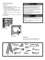 3
3
-
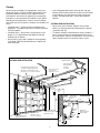 4
4
-
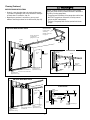 5
5
-
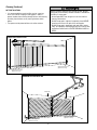 6
6
-
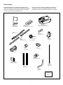 7
7
-
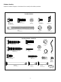 8
8
-
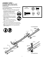 9
9
-
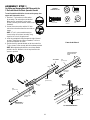 10
10
-
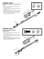 11
11
-
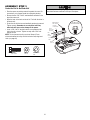 12
12
-
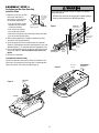 13
13
-
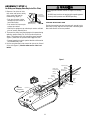 14
14
-
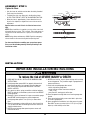 15
15
-
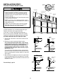 16
16
-
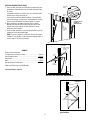 17
17
-
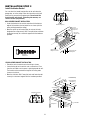 18
18
-
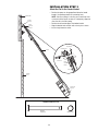 19
19
-
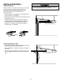 20
20
-
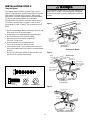 21
21
-
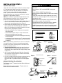 22
22
-
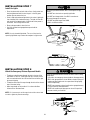 23
23
-
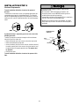 24
24
-
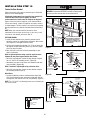 25
25
-
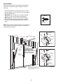 26
26
-
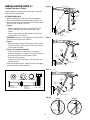 27
27
-
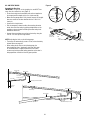 28
28
-
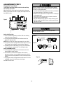 29
29
-
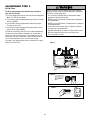 30
30
-
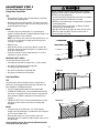 31
31
-
 32
32
-
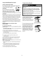 33
33
-
 34
34
-
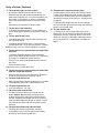 35
35
-
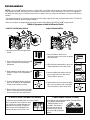 36
36
-
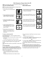 37
37
-
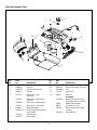 38
38
-
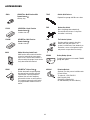 39
39
-
 40
40
-
 41
41
-
 42
42
-
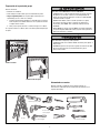 43
43
-
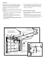 44
44
-
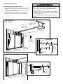 45
45
-
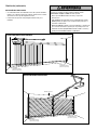 46
46
-
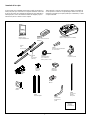 47
47
-
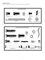 48
48
-
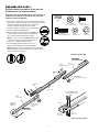 49
49
-
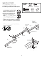 50
50
-
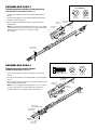 51
51
-
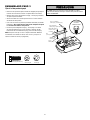 52
52
-
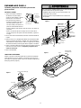 53
53
-
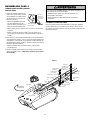 54
54
-
 55
55
-
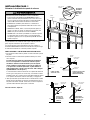 56
56
-
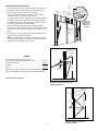 57
57
-
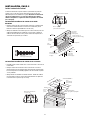 58
58
-
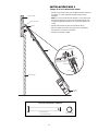 59
59
-
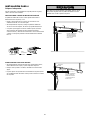 60
60
-
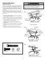 61
61
-
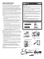 62
62
-
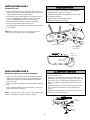 63
63
-
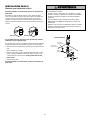 64
64
-
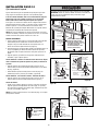 65
65
-
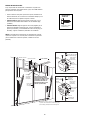 66
66
-
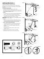 67
67
-
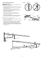 68
68
-
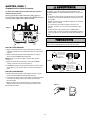 69
69
-
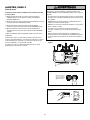 70
70
-
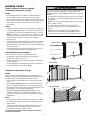 71
71
-
 72
72
-
 73
73
-
 74
74
-
 75
75
-
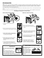 76
76
-
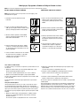 77
77
-
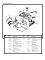 78
78
-
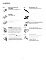 79
79
-
 80
80


Merik 790LMK El manual del propietario
- Categoría
- Abridor de puerta de garage
- Tipo
- El manual del propietario
en otros idiomas
- English: Merik 790LMK Owner's manual
Artículos relacionados


Otros documentos
-
 PortaSeal G9x7 Guía de instalación
-
Craftsman 139.53993DM El manual del propietario
-
-
Chamberlain Security+ 1210E FS2 Manual de usuario
-
Chamberlain 1215E FS2 Manual de usuario
-
-
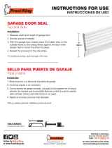 Frost King Dual Vinyl Garage Door side and Top Weatherseal Guía de instalación
-
-
-

