Merik M500 Installation and User Manual
- Categoría
- Abridor de puerta
- Tipo
- Installation and User Manual


7
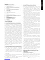
ESPAÑOL
MERIK ®Copyright 2015 - All rights reserved
ÍNDICE
1 ADVERTENCIAS GENERALES
1.1 Advertencias para la seguridad
1.2 Advertencias para la instalación
1.3 Advertencias para el uso
2 MODELOS Y DESCRIPCIÓN DE LOS PRODUCTOS
2.1 Descripción
2.2 Instalación típica
3 CARACTERÍSTICAS TÉCNICAS DEL PRODUCTO
4 INSTALACIÓN
4.1 Controles preliminares
4.2 Límites de utilización
4.3 Trabajos preparativos para la instalación
4.4 Instalación del motorreductor mod. M
4.4.1 Instalación
4.4.2 Instalación de los nales de carrera
4.4.3 Desbloqueo manual del motorreductor
5 PREPARATIVOS PARA LAS CONEXIONES ELÉCTRICAS
6 ENSAYO
7 MANTENIMIENTO DEL PRODUCTO
8 PIEZAS DE REPUESTO
9 ELIMINACIÓN DEL PRODUCTO
10 GARANTÍA
1 ADVERTENCIAS
1.1 ADVERTENCIAS PARA LA SEGURIDAD
El presente manual de instalación está dirigido
exclusivamente al personal profesionalmente
capacitado. Antes de proceder con la instalación
es necesario leer todas las instrucciones. Todo lo
que no esté especicado en estas instrucciones
no está permitido; los usos no previstos podrían ser
una fuente de daño para el producto y ser peligroso
para las personas y bienes. El fabricante declina
toda responsabilidad por la falta de aplicación
de la buena ejecución en la construcción de las
puertas y de las deformaciones que pudieran
producirse durante su uso. Conserve este manual
para futuras consultas. El diseño, la fabricación
de los dispositivos que componen M220, M300,
M500 y el presente manual respetan por completo
la normativa vigente. Teniendo en cuenta las
situaciones de riesgo que pueden producirse
durante la instalación y el uso de M220, M300,
M500, es necesario que también la instalación
se lleve a cabo respetando las leyes, normas y
reglamentos; a saber:
1.2 ADVERTENCIAS PARA LA INSTALACIÓN
• Antes de iniciar la instalación, compruebe
la necesidad de dispositivos y materiales
adicionales que pudieran ser necesarios para
completar la automatización con M220, M300,
M500 de acuerdo con las situación específica
de empleo.
• El automatismo no debe utilizarse antes de haber
realizado la puesta en servicio.
• El material de embalaje debe eliminarse
respetando la normativa local vigente.
1.3 ADVERTENCIAS PARA EL USO
• No realice modicaciones en ninguna pieza
si no estuviera previsto en este manual. Las
operaciones de este tipo pueden provocar
fallos de funcionamiento. El fabricante declina
toda responsabilidad por daños causados por
productos modicados.
• Evite que las piezas del automatismo puedan
quedar sumergidas en agua o en otros líquidos.
Evite que los líquidos puedan penetrar en el interior
del cuadro de control y de otros dispositivos
abiertos incluso durante la instalación.
• Si penetrara líquido en el interior de los dispositivos
del automatismo, desconecte inmediatamente
la alimentación eléctrica y póngase en contacto
con el servicio de asistencia; el uso de M220,
M300, M500 en tales situaciones puede
provocar situaciones peligrosas.
• No conserve ningún componente de M220,
M300, M500 cerca de fuentes de calor ni los
exponga a las llamas porque se podrían dañar
y provocar fallos de funcionamiento, incendio o
situaciones peligrosas.
• En el caso de períodos prolongados de
inactividad, para evitar el riesgo de fugas de
sustancias nocivas de la batería opcional, es
preferible extraerla y guardarla en un lugar seco.
• Conecte el cuadro de control únicamente a una
línea de alimentación eléctrica con puesta a tierra
de seguridad.
• Todas las operaciones que requieren la apertura
de las cubiertas de M220, M300, M500 deben
hacerse con el cuadro de control desconectado
de la alimentación eléctrica; si el dispositivo de
desconexión no estuviera a la vista, aplique
el siguiente cartel: “CUIDADO REALIZANDO
TAREAS DE MANTENIMIENTO”.
• Si los interruptores automáticos o los fusibles
se desconectaran, antes de restablecerlos es
necesario identicar y solucionar el fallo.
• Si no fuera posible solucionar el fallo utilizando
las informaciones indicadas en este manual,
contacte con el servicio de asistencia.
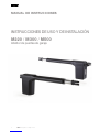
2 DESCRIPCIÓN DEL PRODUCTO Y USO
PREVISTO
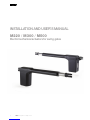
2.1 DESCRIPCIÓN DEL PRODUCTO
Actuador electromecánico telescópico ambidiestro para puertas
residenciales. La estructura robusta de aluminio fundido a presión permite
alojar tanto los motores de escobillas como los motores monofásicos,
poniendo a disposición la versión de 24 V y la versión de110 V.
La carcasa de aluminio con pintura en polvo es resistente a los agentes
atmosféricos.

8
MERIK ®Copyright 2015 - All rights reserved
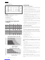
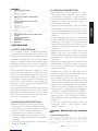
2.2 INSTALACIÓN TÍPICA
E G
CC
F F
F
BB A A
D
LEYENDA
A MOTORREDUCTOR CON CENTRALITA INTERIOR
B FOTOCÉLULAS DE APERTURA
C FOTOCÉLULAS DE CIERRE
D LUZ INTERMITENTE
E SELECTOR DE LLAVE
F TOPE DE FINAL DE CARRERA
G CUADRO DE CONTROL EXTERIOR
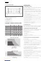
3 CARACTERÍSTICAS TÉCNICAS DEL
PRODUCTO
M 220 M 300 M 500
Alimentación motor 24Vcc 24Vcc
110 ~ 50Hz
24Vcc
110 ~ 50Hz
Potencia absorbida 70 W 110 W 280W 110 W 280W
Absorción 3 A 5 A 1,2 A 5 A 1,2 A
Fuerza máx. 1500 N 2000 N 1800 N 1800 N 2000 N
Empuje Nominal 500 N 600 N 700 N 600 N 700 N
Intermitencia de funcio-
namiento
30% Intensivo 40% Intensivo 30%
Grado de protección IP 24 D
Clase de aislamiento II II 1 (de tierra) II 1 (de tierra)
Temp. de funcionamiento de -20°C a + 50°C
Peso máx. de la puerta VER GRÁFICA
Velocidad 15mm/s 22 mm/s 15mm/s 22mm/s 15mm/s
Peso 7 Kg 7,8 Kg 8,3 Kg 8,8 Kg 9,3 Kg
4 INSTALACIÓN
4.1 CONTROLES PRELIMINARES
Antes de proceder con la instalación es necesario comprobar la integridad
de los componentes del producto, que el modelo sea adecuado y que el
entorno destinado a la instalación sea idóneo:
• Compruebe que todo el material que debe utilizar esté en perfectas
condiciones y sea adecuado para el uso previsto.
• Compruebe que la estructura mecánica de la puerta sea adecuada
para ser automatizada. Este producto no puede automatizar una
puerta que no sea eciente y segura; además, no puede resolver
defectos causados por una instalación incorrecta de la puerta o por un
mantenimiento incorrecto.
• Compruebe que las condiciones de funcionamiento de los dispositivos
sean compatibles con los límites de empleo declarados.
• Mueva manualmente las hojas de la puerta en ambas direcciones y
compruebe que el esfuerzo sea constante.
• Coloque manualmente las hojas de la puerta en cualquier posición;
posteriormente déjelas detenidas y compruebe que no se muevan.
• Compruebe que la zona de jación del motorreductor sea compatible
con el tamaño de este último y compruebe que haya espacio suciente
para la rotación completa de su brazo.
• Asegúrese de que en las cercanías del motorreductor haya espacio
suciente para efectuar la maniobra manual de desbloqueo del mismo
motorreductor.
• Asegúrese de que las supercies elegidas para instalar los distintos
dispositivos sean rmes y garanticen una jación estable.
• Asegúrese de que cada dispositivo que deba instalar esté colocado en
una posición protegida contra los golpes accidentes.
4.2 LÍMITES DE UTILIZACIÓN
Antes de realizar la instalación, compruebe que el tamaño del motor
sea adecuado para el peso y la longitud de las hojas de la puerta y esté
dentro de los valores indicados en el capítulo “Características técnicas del
producto”.
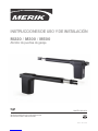
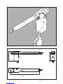
4.3 TRABAJOS PREPARATIVOS PARA LA INSTALACIÓN
Tomando como referencia las FIG. 1A y FIG. 1B, establezca la posición
aproximada de instalación de cada componente previsto en el sistema y el
esquema de conexión más adecuado. A continuación se indica una lista
de los componentes necesarios:
• Motorreductores electromecánicos.
• Par de fotocélulas.
• Par de topes de apertura y topes de cierre.
• Columnas para fotocélulas.
• Luz intermitente.
• Selector de llave o botonera digital.
• Electrocerradura vertical (aconsejada para cerMientos de más de 3 m).
• Cuadro de control.
4.4 INSTALACIÓN DEL MOTORREDUCTOR M220, M300,
M500
4.4.1 INSTALACIÓN
• Realice el desbloqueo manual como se describe en el capítulo 4.4.3.
• Establezca la posición del automatismo en correspondencia de un
travesaño rme.
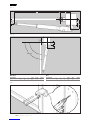
• Fije temporariamente la placa trasera al pilar, que debe tener una
anchura mínima de 100 mm (FIG. 2).
• Con la puerta completamente cerrada, je la placa delantera a la hoja
(FIG. 3).
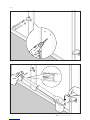
• Una el motor a la placa trasera con el tornillo y la tuerca suministrados
(FIG. 4). El actuador no puede instalarse con la tapa hacia arriba.
• Fije el pistón a la placa delantera utilizando el tornillo y la tuerca
suministrados (FIG. 4).
4.4.2 INSTALACIÓN DE LOS FINALES DE CARRERA
El actuador M220, M300, M500 no incorpora nales de carrera
electrónicos y, por lo tanto, es indispensable instalar en la puerta que se
debe automatizar los topes mecánicos de cierre y apertura.
4.4.3 DESBLOQUEO MANUAL DEL MOTOR
El desbloqueo manual se activa cuando hay que abrir manualmente
la puerta. La activación del sistema de desbloqueo podría provocar
movimientos incontrolados de la puerta en el caso de desajustes o fallos
mecánicos.

9
ESPAÑOL
MERIK ®Copyright 2015 - All rights reserved
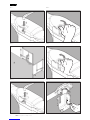
Para desbloquear el motor, siga estos pasos:
• Abra la cubierta de plástico e introduzca la manilla de desbloqueo (FIG.
5).
• Gire la manilla en el sentido horario (FIG. 6).
• De esta manera el engranaje queda libre y es posible abrir manualmente
la puerta (FIG. 7).
• Para restablecer el mando motorizado, coloque la manilla en la posición
original (FIG. 8).
• Quite la manilla y guárdela en un lugar seguro (FIG. 9).
5 PREPARATIVOS PARA LAS CONEXIONES
ELÉCTRICAS
¡ATENCIÓN! Para conectarse a la red, utilice un cable multipolar con la
reglamentación por la unidad del libro.
• Realice el desbloqueo manual como ilustrado en el apartado 4.4.3.
• Quite la pieza de plástico como ilustrado en la FIG. 10.
• Aoje el prensaestopas “G” colocado en la parte inferior del motor FIG.
10.
• Introduzca el cable de alimentación FIG. 11.
• Conecte los cables a la bornera tal como indicado en la etiqueta.
• Conecte la puesta a tierra al terminal con taladro cerca de la bornera FIG.
11. (Para los modelos de la clase I).
• Bloquee el cable apretando el prensaestopas.
6 ENSAYO
Cada elemento del automatismo, por ejemplo bandas sensibles, fotocélulas,
dispositivo de parada de emergencia, etc., requiere una fase de ensayo
especíca; para dichos dispositivos se deberán realizar los procedimientos
indicados en los respectivos manuales de instrucción. Para el ensayo de
M220, M300, M500 realice la siguiente secuencia de operaciones:
• Compruebe que se haya respetado estrictamente todo lo previsto en
este manual y, en particular, en el capítulo “1 Advertencias”.
• Utilizando los dispositivos de mando o de parada previstos
(selector de llave, pulsadores de mando o transmisores), realice
las pruebas de apertura, cierre y parada de la puerta y compruebe
que el comportamiento corresponda con cuanto previsto.
• Compruebe uno por uno el funcionamiento correcto de todos los
dispositivos de seguridad montados en el sistema (fotocélulas,
bandas sensibles, dispositivos de parada de emergencia, etc.).
• Si las situaciones peligrosas provocadas por el movimiento
de la hoja han sido eliminadas por la limitación de la fuerza de
impacto, habrá que medir la fuerza según la Norma EN 12445.
7 MANTENIMIENTO DEL PRODUCTO
Lubricar el vástago cuando sea necesario.
El mantenimiento debe ser realizado regularmente por personal calicado de
acuerdo con las leyes y normativas vigentes. M220, M300, M500 necesita
un mantenimiento progMado al máximo dentro de 6 meses o 10.000
movimientos a partir del mantenimiento anterior.
• Desconecte todas las fuentes de alimentación del motor.
• Compruebe y sustituya todas las piezas móviles desgastadas.
• Compruebe el desgaste de todas las piezas del automatismo.
8 PIEZAS DE REPUESTO
Las piezas de repuesto pueden solicitarse contactando con el servicio de
asistencia técnica.
9 ELIMINACIÓN
Al nal de la vida útil del automatismo, asegúrese de que el desguace sea
realizado por personal calicado y que los materiales sean reciclados o
eliminados según las normas locales vigentes.
10 GARANTÍA
Merik S.A. de C.V garantiza, con sujeción al cumplimiento de las
especicaciones de rendimiento que guran en los manuales de instrucciones
de los productos, el buen funcionamiento de los actuadores durante 24
meses desde la fecha de fabricacion. Merik S.A. de C.V garantiza en
exclusiva, y por lo tanto la exclusion de las reclamaciones por daños y
perjuicios equivalente, a la reparación o reemplazo de piezas defectuosas
que serán reconocidas como tales, de acuerdo a la discreción del personal
técnico de Merik S.A. de C.V. El material en garantia deben enviarse a
la sede de Merik S.A. de C.V en porte pagado y sera devuelto a portes
debido. El material considerado defectuoso y enviado a Merik S.A. de C.V
seguirá siendo propiedad de dicha empresa
El costo de la mano de obra necesaria para las reparaciones y
sustituciones realizadas es sólo del comprador. No tiene derecho a ninguna
compensación por el período de tiempo de inactividad de la instalacion. La
intervención no extende el plazo de duración de la garantía.
Bajo pena de caducidad, el comprador debe informar de cualquier fallo o
defecto de los productos, dentro de los 8 (ocho) días para ser calculados,
respectivamente, desde la fecha del descubrimiento de los defectos o la
fecha de entrega del material. El informe deberá realizarse únicamente por
escrito La garantia no incluye:
Avérias o daños causados por el transporte; avérias o daños causados por
vicios de la instalacion eléctrico presente en el comprador y / o descuido,
negligencia, uso inadecuado, anormal de esta installacion; avéria o daño
debido a la manipulación por parte de personal no autorizado o que
resulten del uso / instalación inadecuados (en este sentido, se recomienda
un mantenimiento del sistema por lo menos cada seis meses) o al empleo
de piezas de repuesto no originales; los defectos causados por agentes
químicos o fenómenos atmosféricos. La garantia no cubre el costo del
material de consumo ni por supuestos defectos o las vericaciones a su
comodidad.
Caracteristicas de los productos Los productos fabricados por Merik S.A.
de C.V están sujetos a continuas mejoras e innovaciones, por lo que las
características constructivas y la imagen de los mismos, pueden sufrir
variaciones incluso sin aviso previo Tribunal competente Ya que el contrato
es perfeccionado mediante
Conrmación de Pedido
en acorde a las instancias legales correspondientes en el país local.


11
ENGLISH
MERIK ®Copyright 2015 - All rights reserved
CONTENTS
1 GENERAL PRESCRIPTIONS
1.1 Safety prescriptions
1.2 Installation prescriptions
1.3 Operating prescriptions
2 MODELS AND PRODUCTS DESCRIPTION
2.1 Description
2.2 Typical installation
3 PRODUCT TECHNICAL SPECIFICATIONS
4 INSTALLATION
4.1 Preliminary checks
4.2 Operating limits
4.3 Preparatory work for installation
4.4 Installing the M operator
4.4.1 Installation
4.4.2 Installation of limit stops and switches
4.4.3 Operator manual release
5 PREPARATION FOR ELECTRICAL CONNECTIONS
6 TESTING
7 PRODUCT MAINTENANCE
8 SPARE PARTS
9 DISPOSAL OF THE PRODUCT
10 WARRANTY
1 PRESCRIPTIONS
1.1 SAFETY PRESCRIPTIONS
This installation manual is addressed exclusively
to professionally skilled personnel. Read all the
instructions carefully before starting the installation
procedures. Any operations that are not expressly
set down in these instructions are to be considered
prohibited; improper use may result in damage to
the product and place persons and property at
risk.
The manufacturer declines all liability for failure
to observe best practices in gate construction
and for any possible deformation that may occur
during use of the product. Store this manual in a
safe place for future reference. The design and
construction of the devices of which model M is
composed and this manual are in full compliance
with statutory legislation.
In consideration of potential hazards that may arise
during the installation and use of M220, M300,
M500, the installation procedures must be carried
out in full compliance with the applicable laws,
standards and regulations; namely:
1.2 INSTALLATION PRESCRIPTIONS
• Before starting the installation procedures
make sure you have any additional devices
and materials that may be required to complete
the M220, M300, M500 gate opener in
consideration of the specic application.
• The gate opener must not be used until the
system has been commissioned as specied
in heading:
• Dispose of packaging materials in compliance
with local regulations.
1.3 OPERATING PRESCRIPTIONS
• No modications can be made to any part of
the product unless specied in this manual.
Unauthorized modication of the product is
likely to lead to malfunctions. The manufacturer
declines all liability for damage caused by
unauthorized modications.
• The parts of the automation system must never
be immersed in water or other liquids. During
the installation procedures ensure that no liquids
penetrate inside the control unit or other open
devices.
• If liquids penetrate any parts of the automation
system disconnect the electrical power supply
immediately and consult Comunello technical
service; the use of M220, M300, M500 in such
conditions may give rise to potentially hazardous
situations.
• Keep all parts of the M220, M300, M500 gate
opener away from heat sources and open
ames; exposure to heat or ames may damage
the devices and cause faults, re, or hazardous
situations.
• When the equipment remains unused for a long
time, remove the optional battery and store it
in a dry place to avoid the risk of leakage of
harmful substances.
• Connect the control unit exclusively to an
electrical power supply line equipped with an
efcient protective earth conductor.
• Any operations that require the housing of
M220, M300, M500 to be opened must be
performed with the control unit and the electrical
power supply disconnected; if the disconnect
device is not clearly visible from where you are
working, attach a warning notice to the effect:
“WARNING - MAINTENANCE IN PROGRESS”.
• In the case of tripping of circuit breakers or
blowing of fuses, nd the fault and remedy it
before resetting the circuit breaker or changing
the fuse.
• If the fault cannot be remedied using the
information given in this manual, consult
technical service.
2 PRODUCT DESCRIPTION AND INTENDED
USE
2.1 PRODUCT DESCRIPTION
Reversible electromechanical operator with telescopic rod for residential
gates. The rugged die cast aluminium structure can accommodate brush
motors or single phase motors, so the operator can be supplied in either a
24V version or a 110V version. Aluminium housing with weather resistant
powder coating.

12
MERIK ®Copyright 2015 - All rights reserved
2.2 TYPICAL INSTALLATION
E G
CC
F F
F
BB A A
D
KEY
A OPERATOR WITH BUILT-IN CONTROL UNIT
B OPENING PHOTOCELLS
C CLOSING PHOTOCELLS
D FLASHING LIGHT
E KEY SELECTOR SWITCH
F LIMIT STOP
G EXTERNAL CONTROL UNIT
3 PRODUCT TECHNICAL SPECIFICATIONS
M220 M300 M500
Operator power supply 24Vcc 24Vcc
110 ~ 50Hz
24Vcc
100 ~ 50Hz
Power consumption 70 W 110 W 280W 110 W 280 W
Current input 3 A 5 A 1,2 A 5 A 1,2 A
Maximum thrust 1500 N 2000 N 1800 N 1800 N 2000 N
Nominal thrust 500 N 600 N 700 N 600 N 700 N
Duty cycle 30% Intensive 40% Intensive 30%
Protection rating IP 24 D
Insulation class 1 (earthing) II II 1
(earthing)
II 1
(earthing)
Working temperature from from -20°C to + 50°C
Max weight of gate leaf SEE THE CHART
Speed 15mm/s 22 mm/s 15mm/s 22mm/s 15mm/s
Weight 7 Kg 7,8 Kg 8,3 Kg 8,8 Kg 9,3 Kg
4 INSTALLATION
4.1 PRELIMINARY CHECKS
Before starting the installation work, check the condition of the product
components, the suitability of the chosen gate opener model and the
suitability of the intended installation environment:
• Ensure that all material used is in perfect condition and t for purpose.
• Make sure that the mechanical structure of the gate is suitable for
automation. This product cannot be used to automate a gate unless the
gate is already in good working order and safe; furthermore, it cannot
remedy defects caused by incorrect installation or lack of maintenance
of the gate.
• Check that the operating conditions of the devices are compatible with
the stated operating limits.
• Move the gate leaves manually in both directions to ensure the force
required is constant throughout the full range of movement.
• Move the gate leaves manually to any position then release them to
check that they remain stationary.
• Check that the area in which the operator is to be mounted is compatible
with the size of the unit and make sure there is sufcient clearance for
the full movement of the arm.
• Ensure that there is sufcient space around the operator to perform the
manual release procedure.
• Ensure that the surfaces on which the devices are to be mounted are
solid and able to provide a secure anchorage.
• Ensure that all devices to be installed are in a protected location such
that minimizes the risk of accidental impact.
4.2 OPERATING LIMITS
Before starting the installation work make sure the operator is correctly sized
in relation to the dimensions and length of the gate leaves and within the
limits of the values given in the chapter “Product technical specications”.
4.3 PREPARATORY WORK FOR INSTALLATION
With reference to FIG. 1A e a FIG. 1B, choose the approximate position
in which each component of the system is to be installed and choose the
most appropriate connection layout. List of components required:
• Electromechanical operators.
• Pair of photocells.
• Pair of opening limit stops and closing stop.
• Posts for photocells.
• Flashing light.
• Key selector switch or digital keypad.
• Vertical electric lock (recommended for gate leaves of more than 3 m).
• Control unit.
4.4 INSTALLING THE M220, M300, M500 OPERATOR
4.4.1 INSTALLATION
Perform the manual release as described in heading 4.4.3
• Choose the position for the gate opener in correspondence with a
sturdy cross member on the gate.
• Temporarily secure the rear plate to the pillar, which must be at least 100
mm in width (FIG. 2).
• With the gate fully closed, x the front plate to the gate leaf (FIG. 3).
• Couple the operator to the rear bracket using the supplied nut and bolt
(FIG. 4). The operator cannot be installed with the cover upward.
• Fix the rod to the front plate with the supplied nut and bolt (FIG. 4).
4.4.2 INSTALLATION OF LIMIT STOPS AND SWITCHES
The M220, M300, M500 operator is not equipped with electronic limit
switches and it is therefore essential to ensure that the gate to be automated
is equipped with mechanical opening and closing limit stops.
4.4.3 OPERATOR MANUAL RELEASE
Perform the manual release procedure when the gate is to be opened
manually. Activation of the release system may result in uncontrolled
movements of the gate in the presence of imbalance or mechanical faults.
To release the operator, proceed as follows:
• Open the plastic hatch and insert the release handle (FIG. 5).
• Turn the handle clockwise (FIG. 6).
• This action serves to disengage the gear thereby allowing the gate to be
opened manually (FIG. 7).
• To resume automatic control of the gate, return the key to its initial
position (FIG.8)
• Remove the release handle and stow it in a safe place (FIG. 9).

13
ENGLISH
MERIK ®Copyright 2015 - All rights reserved
5 PREPARATION FOR ELECTRICAL
CONNECTIONS
WARNING! To connect to the network, use a multipolar cable provided by
regulations by the book’s unit.
• Perform the manual release as illustrated in heading 4.4.3.
• Remove the plastic cover as shown in FIG. 10.
• Loosen cable gland “G” located on the lower side of the operator FIG.
10.
• Insert the power cable FIG. 11.
• Connect the wires to the terminal board as shown on the adjacent label.
• Connect the earth wire to the terminal eye next to the terminal board
FIG. 11. (for models of class I).
• Secure the cable by tightening the cable gland.
6 TESTING
Each part of the automation system, e.g. safety edges, photocells,
emergency stop, etc. must be tested; follow the procedures shown in
the instruction manuals supplied with the devices in question. Perform the
following sequence of operations for testing of M220, M300, M500:
• Check that all the prescriptions in this manual have been followed
scrupulously, with special attention to the matters set down in chapter 1
“Prescriptions”.
• Using the supplied control or stopping devices (key selector switch,
control buttons or radio trasmitters), perform gate opening, closing and
stopping tests and make sure the gate responds correctly to the various
commands.
• Check operation of all the system’s safety devices (photocells, safety
edges, emergency stop, etc.) one by one.
• If potentially hazardous situations caused by movement of the gate leaf
have been eliminated by limitation of impact force, the associated force
must be measured as prescribed in standard EN 12445.
7 PRODUCT MAINTENANCE
Lubricate the spindle when needed.
Maintenance must be carried out at regular intervals by qualied personnel in
compliance with the provisions of statutory legislation and the regulations in
force. M220, M300, M500 must be serviced at least once every 6 months
or after 10.000 operating cycles since the last service.
• Disconnect the operator from all power supplies
• Check all the moving parts and replace any worn parts.
• Check all parts of the automation system for signs of deterioration.
8 SPARE PARTS
Spare parts can be purchased by contacting technical service.
9 DISPOSAL
At the end of its useful life the automation system must be dismantled by
qualied personnel and the materials must be recycled or disposed of in
compliance with the local legislation in force.
10 WARRANTY
Merik S.A. de C.V. provides a warranty for 24 months for the correct
functioning of the actuators from the date of manufacture, provided that the
performance specications indicated in the product instruction manuals are
respected. Free of charge repair and replacement of components that are
found to be faulty according to the indisputable judgment of the company’s
technical staff shall be guaranteed at the sole discretion of Merik S.A. de
C.V., and so excluding any claim for damages made by others. Warranty
material shall be returned to Merik S.A. de C.V. headquarters carriage paid
and will then be shipped to the customer carriage unpaid. The material
found to be faulty and returned to Merik S.A. de C.V. shall remain property
of the Seller. Any cost resulting from any work needed to repair the defect or
to replace the material shall be charged to the Buyer. No compensation shall
be allowed for the period of device inactivity. Work under warranty does not
prolong the warranty period. The defect of the product shall be reported by
the Buyer within 8 (eight) days from its discovery or from the date of delivery
of the goods, under penalty of invalidation of the warranty. Such claim shall
be notied in writing.
Warranty does not cover:
Any product defect or damage that may have been incurred during
transport; any defect or damage arising from any fault and/or from neglect,
inadequacy and misuse of the electrical wiring in the Buyer’s property; any
defect or damage caused by any repairs carried out by non authorised
personnel or by incorrect use/installation (with reference to this, system
maintenance is recommended every 6 months) or if not original spare parts
are used; any defect caused by chemicals or atmospheric conditions. The
warranty does not cover any cost neither for consumable materials nor for
alleged defects or convenient surveys.
Product Features Merik S.A. de C.V. products are subjected to continue
changes and improvements; their technical features and image may
therefore change without previous notice.
Competent court
Since the contract of sale is conrmed by an Order Conrmation, any such
dispute shall be settled as established by the legal agreement of the related
country.

14 MERIK ®Copyright 2015 - All rights reserved
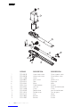
CÓDIGO DESCRIPTION DESCRIPCIÓN
1 RG20861B Upper motor cover Carter superior motor
2 RG20860B Lower motor cover Carter inferior motor
3 RG21206B Cover Tapa
4 RG30983X Worm screw Tornillo sin n
5 RG30522X Gear Engranaje
6 RG20506X Motor Motor
7 RG30102X Cable tightener Pasteca
8 RG20975Z Lock pin Pernio de desbloqueo
9 RG21045B O-ring O-ring
10 RG20815S Release lever Leva de desbloqueo
11 RG21050X Rubber cover Tapa en goma
12 RG20310Z Pivot Pernio
13 RG20489Z Bracket Estribo
14 RG20438Z Bracket Estribo
3
7
2
5
8
9
14
13
4
1
12 11
10
6

15
MERIK ®Copyright 2015 - All rights reserved
7
6
2
8
14
13
4
1
12
11
10
5
9
15
3
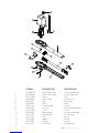
CÓDIGO DESCRIPTION DESCRIPCIÓN
1 RG20861B Upper motor cover Carter superior motor
2 RG20860B Lower motor cover Carter inferior motor
3 RG21206B Cover Tapa
4 RG30983X Worm screw Tornillo sin n
5 RG30522X Gear Engranaje
6 RG30536X Motor Motor
7 RG30102X Cable tightener Pasteca
8 RG20975Z Lock pin Pernio de desbloqueo
9 RG21045B O-ring O-ring
10 RG20815S Release lever Leva de desbloqueo
11 RG21050X Rubber cover Tapa en goma
12 RG20310Z Pivot Pernio
13 RG20489Z Bracket Estribo
14 RG20438Z Bracket Estribo
15 RG20222X Condenser Condensador

-
 1
1
-
 2
2
-
 3
3
-
 4
4
-
 5
5
-
 6
6
-
 7
7
-
 8
8
-
 9
9
-
 10
10
-
 11
11
-
 12
12
-
 13
13
-
 14
14
-
 15
15
-
 16
16


Merik M500 Installation and User Manual
- Categoría
- Abridor de puerta
- Tipo
- Installation and User Manual
en otros idiomas
- English: Merik M500
Artículos relacionados

Otros documentos
-
Alpine MRD-M300 Manual de usuario
-
-
-
SAER SAER SELF-PRIMING JET M 60 Manual de usuario
-
Shimano RD-M200-C Service Instructions
-
Gigaset DL780 Plus Guía del usuario
-
Samsung SNC-M300 Manual de usuario
-
Genius INDUSTRIAL SLIDER Instrucciones de operación