Master Forge 3218LTM El manual del propietario
- Categoría
- Barbacoas
- Tipo
- El manual del propietario

1
Lowes.com/masterfor
g
e
ATTACH YOUR RECEIPT HERE
Serial Number Purchase Date
Questions, problems, missing parts? Before returning to your retailer, call our
customer service department at 1-800-963-0211, 8:00 a.m. to 6:00 p.m., EST,
Monday-Thursday, 8:00 a.m. to 5:00 p.m., EST, Friday.
5
-B
U
RNER
G
A
S
G
RILL
ITEM #0006554
MODEL #3218LTN
Español p. 53
Master Forge & M Design
®
is a registered
trademark of LF, LLC. All rights reserved.
WARNING
1. Do not store or use gasoline or
other flammable vapors and
liquids in the vicinity of this or
any other appliance.
2. An LP tank not connected for
use should not be stored in the
vicinity of this or any other
appliance.
DANGER
If you smell gas:
1. Shut off gas to the appliance.
2. Extinguish any open flames.
3. Open the lid.
4. If the odor continues, keep
away from the appliance and
immediately call your gas
supplier or fire department.
WARNING
For Outdoor Use Only
WARNING
Improper installation,
adjustment, alteration, service
or maintenance can cause
injury or property damage.
Read this instruction manual
thoroughly before installing or
servicing this equipment.
AB13567
○
R
Downloaded from www.Manualslib.com manuals search engine

TABLE OF CONTENTS
2
Lowes.com/masterfor
g
e
Safety Information ................................................................................................................3
Safety Tips……………………………………………………………………………………………5
Package Contents .................................................................................................................6
Hardware Contents ...............................................................................................................8
Preparation ............................................................................................................................8
Assembly Instructions ..........................................................................................................9
Cooking with Gas ................................................................................................................24
Operating Instructions ........................................................................................................31
Care and Maintenance .........................................................................................................38
Troubleshooting ..................................................................................................................46
Warranty ...............................................................................................................................49
Replacement Parts List .......................................................................................................50
Downloaded from www.Manualslib.com manuals search engine

SAFETY INFORMATION
3
Lowes.com/masterfor
g
e
12.2 in.
18 in.
8 in.
13.9 in.
Please read and understand this entire manual before attempting to assemble, operate
or install the product. If you have any questions regarding the product, please call
customer service at 1-800-963-0211, 8:00 am to 6:00 pm, EST, Monday- Thursday, 8:00
a.m. to 5:00 p.m., EST, Friday.
1 The installation of this appliance must conform with local codes or, in the absence of local
codes, with either the National Fuel Gas Code, ANSI Z223.1/NFPA 54, or Natural Gas and
Propane Installation Code, CSA/CGA-B149.1.
2 This grill is intended for use outdoors and should not be used in a building, garage or any
other enclosed or covered area.
3 This outdoor grill is not intended for installation in or on recreation vehicles and/or boats.
4 A minimum clearance of 36 inches from combustible constructions to the sides of the grill
and 36 inches from the back of the grill to combustible constructions must be maintained.
This outdoor cooking gas appliance must not be placed under overhead combustible
construction.
5 The use of an electrical source requires that when installed, the grill must be electrically
grounded in accordance with local codes or, in the absence of local codes, with
ANSI/NFPA 70, or the Canadian Electrical Code, CSA C22.1. Keep electrical supply cords
and the fuel supply hose away from heated surfaces.
6 Inspect the hoses before each use for excessive abrasion or wear, or cuts that may affect
safe operation of the grill. If there is evidence of excessive abrasion or wear, or the hose is
cut, it must be replaced prior to the grill being put into operation. The replacement hose
assembly must be those specified by the manufacturer.
7 Keep your grill in an area clear and free from combustible materials, gasoline and other
flammable vapors and liquids.
8 DO NOT obstruct the flow of combustion and ventilation air to this appliance.
9 Keep the ventilation openings of the tank enclosure free and clear from debris.
10 Check all gas connections for leaks with a soapy water solution and brush. Never use an
open flame to check for leaks.
11 Never use charcoal in the grill.
12 Never use the grill in windy areas.
13 Only a 20 lb. LP-gas cylinder is allowed. The cylinder must be
constructed and marked in accordance with the Specifications for
LP Gas Cylinders of the U.S. Department of Transportation (D.O.T.)
or the National Standard of Canada, CAN/CSA-B339, Cylinders,
Spheres and Tubes for Transportation of Dangerous Goods; and
Commission. A 20 lb LP-Gas cylinder dimensions are:
14 Never use the grill without the drip tray installed and pushed completely into the back of
the grill. Without the drip tray, hot grease and debris could leak downward and produce a
fire hazard.
Downloaded from www.Manualslib.com manuals search engine

SAFETY INFORMATION
4
Lowes.com/masterfor
g
e
15 The pressure regulator for LP-gas grill is set for 11-in. water column (WC). Natural gas grill
provides a hose assembly which includes a quick-disconnect device. But no pressure
regulator. The LP pressure regulator or the Natural gas hose assembly must be used.
Replacement pressure regulators and hose assemblies must be those specified in the
part list.
16 The cylinder used must include a collar to protect the cylinder valve.
17 Do not store a spare LP-gas cylinder under or near this appliance.
18 Never fill the cylinder beyond 80 percent full.
19 If the information in “17” and “18” is not followed exactly, a fire
causing death or serious injury may occur.
20 The natural gas grill and its individual shutoff valve must be disconnected from the gas
supply piping system during any pressure testing of that system at test pressures in
excess of 0.5 psi (3.5 kPa).
21 The outdoor cooking gas appliance must be isolated from the gas supply piping system by
closing its individual manual shutoff valve during any pressure testing of the gas supply
system at test pressures equal to or less than 1/2 psi (3.5kPa).
22 CALIFORNIA PROPOSITION 65 WARNING: The burning of gas cooking fuel generates
some byproducts which are on the list of substances known by the State of California to
cause cancer, reproductive harm, or other birth defects. To reduce exposure to these
substances, always operate this unit according to the use and care manual, ensuring you
provide good ventilation when cooking with gas.
IMPORTANT: We urge you to read this manual carefully and follow the recommendations
enclosed. This will ensure you receive the most enjoyable and trouble-free operation of your
new gas grill. We also advise you retain this manual for future reference.
WARNING: Your grill has been designed to operate using only the gas specified by the
manufacturer on the rating plate. Do not attempt to operate your grill on other gases. Failure
to follow this warning could lead to a fire hazard and bodily harm and will void your warranty.
WARNING: Make certain your LP (propane) tank is filled by a reputable propane dealer. An
incorrectly filled or an overfilled LP tank can be dangerous. The overfilled condition combined
with the warming of the LP tank (a hot summer day, tank left in the sun, etc.) can cause LP
gas to be released by the pressure relief valve on the tank since the temperature increase
causes the propane to expand. LP gas released from the tank is flammable and can be
explosive. Refer to your Owner’s Manual for more information concerning filling your LP tank.
This unit contains one or more patent pending:
61/163,753
61/215,319
11/495,104
11/268,051
Downloaded from www.Manualslib.com manuals search engine

SAFETY TIPS
5
Lowes.com/masterfor
g
e
Never pull your grill. Always push it.
Never move your grill while it is in operation or still hot.
Always use a protected hand when cleaning the grid surface after the post-heating period
and when closing the propane tank valve.
Use a covered hand during the grilling period.
Wait until the burner box has completely cooled before reaching under to turn off the gas.
Using an uncovered hand to turn off the LP tank valve without allowing the grill to cool
down could result in severe burns.
Never operate your grill under overhangs, awnings or any covered or enclosed area.
Never spray liquid on the grid area to control flare ups.
To guard against possible grease fires getting out of control, never leave a grill
unattended. Grease fires can be severe and cause grill damage, property damage and
bodily harm.
Always turn off the control knob first, and then the propane gas supply tank.
Never cover your grill while it is still warm.
Position your portable grill away from direct wind.
Do not store or use gasoline or other flammable substances in the vicinity of your gas grill.
Never store a propane tank (whether full or empty) inside your home or living area.
Before storing your tank, make sure that it has been turned to the “OFF” position.
Should you store your grill indoors, be sure to close the tank valve, disconnect the hose
from the tank, remove the tank from the grill and store the tank outdoors.
Make sure the grill hood is completely open before lighting your grill.
When connecting or replacing any gas fittings, all joints must be sealed with an approved,
leak-proof sealing compound.
Never use an open flame to test for gas leaks.
When your grill is not in use, it is recommended that for child safety, you remove the
control knobs and store them indoors.
Keep children away from the grill at all times.
Never drill out any orifice or make any field alterations to your grill without receiving
approval from the manufacturer.
Do not store flammable materials in any of the cabinets beneath the grill burner box or in
the vicinity of your grill.
Be careful while handling any parts during assembly. It is strongly recommended that you
protect your hands with a pair of work gloves.
At high temperatures some stainless grids may discolor over time. When the grill is cool,
wiping with a towel and vegetable oil may remove and treat some of this effect. Some
discoloration is normal.
Downloaded from www.Manualslib.com manuals search engine


PACKAGE CONTENTS
7
Lowes.com/masterfor
g
e
Part Description Quantity Part Description Quantity
A Burner Box 1 Q Locking Caster 2
B Heat Tent 5 R Transformer 1
C Main Grid 3 S Main Bottom Panel 1
D Warming Rack 1 T Caster 2
E Sear Burner Grid 1 U Right Door 1
F
Sear Burner
Drip Tray
1 V Right Skirt 1
G Grill Handle 1 W Main Beam 1
H Battery 5 X Center Door 1
I Left Rear Panel 1 Y Left Door 1
J Right Rear Panel 1 Z Left Skirt 1
K Center Panel 1 AB Left Panel 1
L Door Magnet 2 AC
Patented Safety Tank
Ring
1
M Bracket, Tank Ring 1 AD Buffet Table 1
N Shelf board 1 AE Drip Tray Support 1
O Tank Support 1 AF Main Burner Drip Tray 1
P Right Panel 1 AG Battery Box 1
Downloaded from www.Manualslib.com manuals search engine

HARDWARE CONTENTS
8
Lowes.com/masterfor
g
e
PREPARATION
Before beginning assembly of product, make sure all parts are present. Compare parts
with package contents list and diagram above. If any part is missing or damaged, do not
attempt to assemble the product. Contact customer service for replacement parts.
Estimated Assembly Time: 50 minutes by 2 people
Tools Required for Assembly: Phillips screwdriver (sold separately)
AA BB DD EE CC
1/4-20 x 5/8 in.
Screw
Qty. 57
5/32-32 x 3/8 in.
Screw
Qty. 6
Flat Head 5/32-32
x 1/2 in. Screw
Qty. 8
3/16-24 x 1/2 in.
Screw
Qty. 4
Nut
Qty. 2
FF
Wrench
Qty. 1
Downloaded from www.Manualslib.com manuals search engine

ASSEMBLY INSTRUCTIONS
9
Lowes.com/masterfor
g
e
WARNING: The grill should be assembled and placed on a flat level surface.
Compare the parts and hardware with the list and diagrams. Do not attempt assembly if
any part is missing or damaged.
1. Align the casters (Q and T) with the holes
of the main bottom panel (S).
Use the wrench (FF) to tighten. When this
process is completed, turn the bottom panel
over.
The two locking casters (Q) should be at
the back of the grill. (Fig. 1)
2. Attach the tank support (O) to the main
bottom panel (S) with six screws (BB).
(Fig. 2)
Hardware Used
1/4-20 x 5/8 in.
Screw
X 6
BB
2
BB
O
S
S
1
T
Q
Downloaded from www.Manualslib.com manuals search engine

ASSEMBLY INSTRUCTIONS
10
Lowes.com/masterfor
g
e
3. Align the holes in the left rear panel (I)
with the holes in the main bottom panel (S) and
insert the screws (BB) into the aligned holes.
(Fig. 3)
Note: Do not tighten the screws completely.
Leave at least one full turn on each.
After all the screws have been installed,
go back and tighten them fully.
4. For left panel (AB), there are six
screws (BB) to connect to the left rear panel (I)
and main bottom panel (S), three in the rear
and three inside the cabinet. Insert the screws
into the aligned holes and tighten them. The
three screws inside the cabinet should be
engaged first. (Fig. 4)
Hardware Used
1/4-20 x 5/8 in.
Screw
X 4
BB
Hardware Used
1/4-20 x 5/8 in.
Screw
X 6
BB
3
I
S
BB
4
AB
I
BB
S
Downloaded from www.Manualslib.com manuals search engine

ASSEMBLY INSTRUCTIONS
11
Lowes.com/masterfor
g
e
5. Align the holes in the Center Panel (K)
with the holes in the main bottom panel (S)
and insert the screws (BB) into the
aligned holes and tighten them. (Fig. 5)
Note: Do not tighten the screws completely.
Leave at least one full turn on each.
6. For right rear panel (J), there are four
screws (BB) to connect to the left rear panel (I)
and main bottom panel (S), three in the rear
and one inside the cabinet. Insert the screws
into the aligned holes. After all the screws
have been installed, tighten the three screws
installed during step 5 and the one inside the
cabinet first, and then tighten the three in the
rear. (Fig. 6)
Hardware Used
1/4-20 x 5/8 in.
Screw
X 3
BB
Hardware Used
1/4-20 x 5/8 in.
Screw
X 4
BB
5
K
S BB
6
J
BB
I
S
Downloaded from www.Manualslib.com manuals search engine

ASSEMBLY INSTRUCTIONS
12
Lowes.com/masterfor
g
e
7. Slide the tank ring bracket (M) to the end
of the patented safety tank ring (AC) as shown.
Then align the holes in the ring bracket with
left rear panel (I), insert screws (BB)
into the holes from outside of grill, and then
tighten completely.
(Fig. 7)
8. For the door magnet (L), there are four
screws (CC) to connect to the center panel (K).
Insert the screws into the aligned holes and
tighten them. (Fig. 8)
Hardware Used
1/4-20 x 5/8 in.
Screw
X 2
BB
7
BB
M
AC
I
8
CC
L
K
CC
Hardware Used
5/32-32 x 3/8 in.
Screw
X 4
Downloaded from www.Manualslib.com manuals search engine

ASSEMBLY INSTRUCTIONS
13
Lowes.com/masterfor
g
e
9. For right panel (P), there are six screws
(BB) to connect to the right rear panel (J) and
the main bottom panel (S), three in the rear and
three inside the cabinet. Insert the screws into
the aligned holes and tighten them. The three
screws inside the cabinet should be engaged
first. (Fig. 9)
10. For shelf board (N), there are four screws
(BB) to connect to the center panel (K) and
the right panel (P).
Insert the screws into the aligned holes and
tighten them. (Fig. 10)
Hardware Used
1/4-20 x 5/8 in.
Screw
X 6
BB
Hardware Used
1/4-20 x 5/8 in.
Screw
X 4
BB
10
K
P
BB
N
9
J
P
BB
S
Downloaded from www.Manualslib.com manuals search engine

ASSEMBLY INSTRUCTIONS
14
Lowes.com/masterfor
g
e
11. For left skirt (Z), there are four screws (BB)
to connect to the left panel (AB) and main bottom
panel (S), two in the left panel and two inside
the cabinet. Make sure the tab A is locked in place.
Insert the screws into the aligned holes and tighten
them. The two screws inside the cabinet should be
engaged first. (Fig. 11)
12. Insert the “Tab A” in right skirt (V) into
the square hole in the Center Panel (K) and
push down. Make sure the tab is locked in
place. For this skirt, there are four screws
(BB) to connect to the center panel (K) and
main bottom panel (S), two in the middle
panel and two inside the cabinet. Insert the
screws into the aligned holes and tighten them.
The two screws inside the cabinet should be
engaged first. (Fig. 12)
Hardware Used
1/4-20 x 5/8 in.
Screw
X 4
BB
Tab A
12
BB
V
K
S
11
BB
Z
AB
S
Tab A
Hardware Used
1/4-20 x 5/8 in.
Screw
X 4
BB
Downloaded from www.Manualslib.com manuals search engine

ASSEMBLY INSTRUCTIONS
15
Lowes.com/masterfor
g
e
13. Align the holes in the hinges of the two
doors (X and Y) with the two skirts (V and Z),
insert flat head screws (DD) into the holes,
and then tighten. (Fig. 13)
14. Align the holes in the main beam (W)
with side panels (P and AB) and two skirts
(V and Z), insert screws (BB) into the holes,
and then tighten.
There are four screws to connect the side
panels and two screws to connect the skirts.
(Fig. 14)
Hardware Used
1/4-20 x 5/8 in.
Screw
X 6
BB
Hardware Used
Flat Head 5/32-32
x 1/2 in. Screw
X 8
DD
Y
X
DD
13
V
Z
P
W
14
V
Z
BB
AB
Downloaded from www.Manualslib.com manuals search engine

ASSEMBLY INSTRUCTIONS
16
Lowes.com/masterfor
g
e
15. For right door (U), insert bottom hinge
pin into hole in the main bottom panel (S).
Push down on top hinge pin to insert into
hole on the main beam (W). Loosen the
screws holding the magnets to center
panel (K). Adjust magnets to contact the
right door, then tighten the screws again.
(Fig. 15)
16. Align the holes in the drip tray support
(AE) with the holes in the main beam (W)
and in the left rear panel (I). Insert screws (BB)
into the holes and tighten them.
Note the orientation of the drip tray support
as shown. (Fig. 16)
Hardware Used
1/4-20 x 5/8 in.
Screw
X 4
BB
16
BB
AE
W
I
U
W
15
K
S
Downloaded from www.Manualslib.com manuals search engine

ASSEMBLY INSTRUCTIONS
17
Lowes.com/masterfor
g
e
17. Slide the main burner drip tray (AF)
between the drip tray support (AE) from
the back of grill. (Fig. 17)
18. Attach the battery box (AG) to the left
panel (AB) with screws (CC) and nuts (AA).
(Fig. 18)
17
AF
AE
CC
AA
AG
AB
18
Nut
CC
5/32-32 x 3/8 in.
Screw
X 2
Hardware Used
AA
X 2
Downloaded from www.Manualslib.com manuals search engine

ASSEMBLY INSTRUCTIONS
18
Lowes.com/masterfor
g
e
19. Take the pressure regulator out from under
the burner box (A). Then lift the burner box (A)
onto the cabinet, making sure that the gas
pressure regulator is in the cabinet, then position
burner box on the cabinet by aligning the four
tabs on top of the cabinet with the holes in the
burner box. Fasten the burner box to the
cabinet with 4 screws (BB). (Fig. 19)
20. Route the light wire from the burner box (A)
through the bottom of the burner box into the
cabinet. Then pull the wire through the
opening in the left rear panel (I).
(Fig. 20)
Hardware Used
1/4-20 x 5/8 in.
Screw
X 4
BB
I
light wire
20
BB
19
A
Tab
Pressure
regulator
Downloaded from www.Manualslib.com manuals search engine

ASSEMBLY INSTRUCTIONS
19
Lowes.com/masterfor
g
e
21. Connect the connector which is on the end
of the light wire from step 20 to the transformer (R).
Push the connector to mate firmly with the
transformer. Then, screw and tighten the cap on
the connector. (Fig. 21)
22. On the NG model, pass the natural
gas hose through the hole in the left rear
panel (I) to your gas supply system.
(Fig. 22)
23. Move the covers away the bases of the
grill handle (G), align the holes in the
bases with the holes of the burner box (A).
Insert screws (EE) into the aligned holes
and then tighten them. After tightening the
screws, move the covers onto the bases.
(Fig. 23)
22
NG hose
I
EE
23
G
A
I
R
21
connector
Hardware Used
3/16-24 x1/2 in.
Screw
X 4
EE
Downloaded from www.Manualslib.com manuals search engine

ASSEMBLY INSTRUCTIONS
20
Lowes.com/masterfor
g
e
24. Loosen the eight screws in the side
panel of burner box and the bottom panel
three turns. This will allow for quick assembly
of the buffet table. (Fig. 24)
25. Align the holes of the hinges in the
buffet table (AD) with the holes in the burner
box and the main bottom panel.
Tighten the eight screws loosened during
step 24. (Fig. 25)
24
25
AD
Downloaded from www.Manualslib.com manuals search engine

ASSEMBLY INSTRUCTIONS
21
Lowes.com/masterfor
g
e
26. Slide the sear burner drip tray (F) from
the back of burner box (A) to the sear burner
bracket. (Fig. 26)
27. Put a battery (H) into the electronic
ignition with correct pole direction.
(Please refer to the battery mark on the
side of the cap). Push and turn the knobs to
check if there are sparks produced between
the ignition pin and the main burner.
If not, please refer to the troubleshooting
section to solve the problem.
(Fig. 27)
26
F
A
Sear burner bracket
27
H
Downloaded from www.Manualslib.com manuals search engine

ASSEMBLY INSTRUCTIONS
22
Lowes.com/masterfor
g
e
28. Connect the joint of the battery box (AG)
with the joint of the LED light wire.
(Fig. 28)
Note: 4 batteries included in the package
must be put into the battery box.
29. Position the sear burner grid (E),
5 heat tents (B), 3 main grids (C),
and 1 warming rack (D) into place.
(Fig. 29)
29
D
C
B
E
28
Joint
AG
AB
Downloaded from www.Manualslib.com manuals search engine

ASSEMBLY INSTRUCTIONS
23
Lowes.com/masterfor
g
e
IMPORTANT
CHECK SPARKS
After you complete your grill assembly, test your ignition system with the GAS OFF.
Check for continuous sparks when pushing in the knob ignition system.
For the side burner, sparks can be seen directly. For main burners, the ignition system
is positioned next to each burner inside the burner box. A reflection of sparks or sparks
can be seen at the front of the inside of the burner box. Or you can place a mirror on the
left of each main burner and see the sparks and hear the click of the igniters. Be sure the
GAS IS OFF when you push in the control knobs. This will help assure a trouble-free
ignition when you turn on the gas.
ASSEMBLED GRILL DIMENSION (INCHES):
48.5 (HEIGHT) x 81.9 (WIDTH) x 24.8 (DEPTH) (TABLE FOLDED OUT)
48.5 (HEIGHT) x 52.5 (WIDTH) x 24.8 (DEPTH) (TABLE FOLDED DOWN)
WARMING RACK AREA (SQUARE INCHES): 211
THE UL LABEL IS ON THE BACK OF THE DOOR, SHOWN AS PICTURED BELOW
.
Downloaded from www.Manualslib.com manuals search engine

COOKING WITH GAS
24
Lowes.com/masterfor
g
e
For Portable LP-Gas Connection
The cabinet has an opening in the bottom panel that allows a 20 lb. gas tank bottom flange to
drop into place (tank sold separately). This will help to lock the tank in place. Before installing
your gas tank, lift up the patented safety tank ring (as shown in Fig. 29a). After positioning the
tank in the opening, lower the patented safety tank ring to lock the tank. Use only 20 lb. gas
tank (see LP Gas Safety Requirements for Additional Information). As shown in Fig. 29b, it
is unsafe to operate the grill if the gas tank is not vertical.
Fig. 29a Fig. 29b
Fig. 30
The propane tank valve connection supplied with this grill incorporates the four important safe
guards: Hand Assembly, Hand Disassembly, Excess Flow Control and Temperature-Activated
Shut-Off.
WARNING: The Type I connective coupling (see Fig. 30) supplied with your grill must
not be replaced with a different type of grill/tank connection system. Removal will
result in loss of warranty, gas leakage, fire and severe bodily harm.
HAND WHEEL
TYPE I VALVE
EXTERNAL
THREAD
THERMALLY
SENSITIVE NUT
PROPANE
REGULATOR
LP Tank
Downloaded from www.Manualslib.com manuals search engine

COOKING WITH GAS
25
Lowes.com/masterfor
g
e
a. Hand Assembly:
1. Make certain the tank valve and all the appliance valves are in the “OFF” positions.
2. When connecting the regulator/burner valve assembly to the tank valve, turn the large
plastic nut clockwise until it stops.
3. Gas will not flow unless the plastic nut is completely connected.
4. HAND TIGHTEN ONLY.
b. Hand Disassembly:
1. Make certain the tank valve and all the appliance valves are in the “OFF” positions.
2. Turn the large plastic nut counter-clockwise until it is disassembled.
3. HAND LOOSEN ONLY.
c. Excess Flow Control and Low Heat
The propane regulator assembly incorporates an excess flow device designed to supply the
grill with sufficient gas flow under normal conditions yet control excess gas flow.
Rapid changes in pressure can trigger the excess flow device providing a low flame and low
temperature. If the tank valve is turned open to allow gas flow while a burner valve is open,
the surge of pressure will cause the device to activate. The device will remain closed until the
pressure is equalized. This should occur within 5 seconds.
To ensure this does not cause difficulty in lighting the grill, follow these instructions:
1. Make sure all burner valves are “OFF”.
2. Open the tank valve and wait 5 seconds.
3. Light the burners one at a time following the lighting instructions.
d. Temperature-Activated Shut-Off
The large plastic nut on the regulator assembly is designed in coordination with a check valve
in the tank valve to shut off the flow of gas when exposed to temperatures between
240-300° F.
In the event of a fire or hose break, one of the safeguards will function to control or stop the
flow of gas from the propane tank. Never attempt to use damaged equipment.
Important: Before the use of a fresh tank of gas, please check leakage around the
connections according to section ‘Checking Gas Leaks’ , and make sure there is no
leakage or vapor accumulation in the cabinet. Make sure all openings around side
walls are not blocked.
Important: Place dust cap on cylinder valve outlet whenever the cylinder is not in use.
Only install the type of dust cap on the cylinder valve outlet that is provided with the
cylinder valve. Other types of caps or plugs may result in leakage of propane.
Downloaded from www.Manualslib.com manuals search engine

COOKING WITH GAS
26
Lowes.com/masterfor
g
e
For Natural Gas Connection
Preparing:
1. Turn off gas supply, and then remove cap on gas supply side.
2. Recommended: Install a shut-off valve on gas supply side before installing the socket.
3. Socket should be installed by an authorized technician in accordance with the national
fuel gas code (NFPA 54/ANSI223.1).
4. Before inserting plug, turn on gas supply and leak test all connections including the stem
of the shut-off valve and the opening of the socket. For best results, use an
ammonia-free soap and water solution.
Operating Instructions:
1. To connect, push back socket sleeve (Fig. 31).
2. Insert plug and release sleeve (Fig. 32).
3. Push plug until sleeve snaps forward (Fig. 33).
(Gas will flow automatically. Failure to connect
plug properly to socket will inhibit gas flow to
the appliance.)
Fig. 33
4. Test connection with ammonia-free soap and water solution.
To disconnect
1. Pull sleeve back. Pull plug out of socket. (Gas is automatically shut off.)
2. Close shut-off valve and replace dust caps on socket and plug.
Gas Requirements
The 3218LTN grill is set and tested at the factory for the type of gas supply to be used.
Identify the type of gas, either natural gas or LP gas, and make sure the marking on the rating
plate matches the gas supply. The rating plate is located on the inside panel of the left door.
Sleeve
Socket
Plug
Socket
Sleeve
Fig. 31
Sleeve
Socket
Fig. 32
Downloaded from www.Manualslib.com manuals search engine

COOKING WITH GAS
27
Lowes.com/masterfor
g
e
LP Gas
If your grill is for LP Gas, the regulator supplied is set for an 11-in. water column (WC) and is
for use with LP gas only. The factory-supplied regulator and hose must be used with a 20-lb.
LP gas tank.
Natural Gas
Your grill 3218LTN is natural gas convertible. NG kit sold separately (Item #0050772). Please
follow the manual to convert your grill to natural gas.
If your grill is for Natural Gas, it is set for a 7-in. water column (WC) and is for use with Natural
Gas only. Gas pressure is affected by gas line size and the length of gas line run from the
house gas line. Follow the recommendations in the chart below.
From House to Grill
Distance Tubing Size
Up to 25 ft. 3/8 in. DIA
26-50 ft. 1/2 in. DIA
51-100 ft.
2/3 in. of run 3/4 in.
1/3 in. of run 1/2 in.
Over 101 ft. 3/4 in. DIA
LP GAS System
Contact your gas supplier for a special regulator for bulk gas that fuels other
appliances.
Gas Consumption
Total gas consumption of this grill with the burner(s) on “HIGH”: Table 1 below.
Table 1
Burner Type BTU/HR
Main Burners 12000 x 5
Sear Burner 12000 x 1
Rotisserie Burner 13000 x 1
LP Gas Safety Requirement
For LP gas grills, the LP gas supply tank to be used must be:
(a) Constructed and marked in accordance with the Specifications for LP Gas Tanks of the
U.S. Department of Transportation (DOT) or the National Standard of Canada,
CAN/CSA-B339 Cylinders, Spheres and Tubes for Transportation of Dangerous Goods;
and Commission, as applicable.
(b) Provided with a listed Overfill Prevention Device (OPD).
Downloaded from www.Manualslib.com manuals search engine

COOKING WITH GAS
28
Lowes.com/masterfor
g
e
(c) Provided with a tank connection device compatible with the connection for outdoor
cooking appliances.
The tank should be 12 inches in diameter and 18-1/2 inches tall and be equipped with a
Type-1 fitting.
The tank supply system must be arranged for vapor withdrawal.
The tank used must include a collar to protect the cylinder valve.
Do not operate the gas grill indoors or in any enclosed area. If the gas grill is not in use, the
gas must be turned off at the supply tank. If the grill is to be stored indoors, disconnect the
gas supply tank and store the tank in an upright position in a cool, well-ventilated outdoor
location away from your grill or any other heat source.
When checking for gas leaks, do not use an open flame. Use a soapy water solution and
apply it to the pipe joints and fittings with a brush and check for bubbles. Check flexible hoses
for cuts and wear that may affect the safe operation of the grill. Only the factory supplied hose
and regulator must be used. Use only replacement regulator and hose assemblies specified
by manufacturer.
Checking Gas Leaks
Before operating your grill, after refueling, check carefully to be certain that all connections
are tight and there are no gas leaks.
1. Make 2-3 ounces of leak solution by mixing liquid dishwashing soap with water.
2. Make certain all control knobs are in the “OFF” position.
3. Brush small amounts of the leak solution on all the fittings and turn the gas on.
4. If bubbles appear, there is a leak. Proceed to step 5.
5. Turn the gas off and tighten all connections.
6. Go back to step 1 to retest the fittings.
7. If bubbles continue to appear, turn the gas off. Contact customer service.
WARNING: Never use a match or open flame for leak detection. Use of an open flame
could result in a fire, explosion and bodily harm.
IMPORTANT: When connecting or replacing any gas pipe or fittings, all joints must be
sealed with approved leak-proof sealing compound or plumber’s tape.
Handling the Liquid Propane Tank Safely
Remember to handle your portable liquid propane tank carefully when you take it to your
dealer for a refill. Avoid dropping it or bumping it against sharp objects. Liquid propane tanks
are sturdily constructed, but a series of hard jolts could damage the container.
Downloaded from www.Manualslib.com manuals search engine

COOKING WITH GAS
29
Lowes.com/masterfor
g
e
When transporting the tank to your local propane gas dealer, make sure the valve is closed
tightly and the protective cover is in place. Position the tank securely in an upright position so
it will not roll around your vehicle.
If you plan to make stops for shopping or errands, have your liquid propane tank filled at the
last stop before going home. Again, make certain the refilled tank is secure and in an upright
position. When you return home, remove the refilled tank from your vehicle. Never leave a
portable liquid propane tank inside a vehicle that may become overheated by the sun.
Your local liquid propane gas dealer will gladly offer you additional safety tips.
Storing the Liquid Propane Tank Safely
Whether you are between cross-country treks in your recreational vehicle or looking for a
place to keep the liquid propane tank to provide fuel for your outdoor grill, keep in mind some
basic safety rules about storing portable liquid propane tanks:
Do not store the tanks (whether full or empty) inside your home, the living area of an R.V., a
garage, basement or workshop. It is unlikely that liquid propane will leak from the tanks. If it
should leak, the fuel could be exposed to sparks from automobiles, power tools or other
appliances. When storing or transporting your LP tank, it must remain in an upright position.
Never lay your LP tank down on its side whether it is full or empty. Never store a spare tank
under or near your grill.
CAUTION: Never transport or move your grill or grill tank without first closing the
manual valve on your liquid propane gas tank.
The best place to store a liquid propane tank is in a shady or protected spot outdoors, behind
your home or garage, or on a screened porch but where it is out of reach of children. Liquid
propane will not evaporate. It is in a strong, closed container. It will not lose any of its
clean-burning heat content, even if left outside year-round.
WARNING: When not connected to your grill, the LP gas tank must be stored in an
upright position in a cool, shady, well-ventilated, outdoor location away from your grill
or any other heat source. Failure to follow this warning could lead to tank valve
damage, fire hazard and personal injury.
Refilling a Propane Tank
It is extremely important that your LP tank be filled properly when you take it to be refilled. Be
sure to use a reputable LP dealer and observe how the tank is filled and at what capacity. An
overfilled LP tank can be dangerous.
Downloaded from www.Manualslib.com manuals search engine

COOKING WITH GAS
30
Lowes.com/masterfor
g
e
The proper way to fill a tank is by weight. The empty tank should be placed on a scale. The
scale weights should be readjusted to a weight that would allow up to 80% of the total weight.
The filling operation must end once the tank is filled to 80% of its total capacity. If the tank is
not completely empty, the scale readjustment must be changed to consider the propane (LP)
already in the tank.
WARNING: An LP (propane) tank is overfilled if it contains more than 80% of its total
capacity of propane (LP).
An incorrectly filled or an overfilled LP (propane) tank can be dangerous. If a tank is overfilled
and the weather causes the warming of the LP tank, (a hot day, tank left in sun or stored
indoors) internal pressure is created due to expansion of the propane which in turn may
cause the LP gas to be released through the pressure relief valve on the tank. The pressure
relief valve is a safety device required on 20 lb. propane tanks by the Department of
Transportation to prevent a catastrophic tank failure due to excessive pressure. LP gas
released from the tank is flammable and can be explosive.
IMPORTANT: When connecting or replacing gas pipe or fittings, all joints must be
sealed with approved leak-proof sealing compound or plumber’s tape. After making
connections, check all joints for leaks using a soapy water solution and a brush.
WARNING: Never use an open flame to test for gas leaks. Use of an open flame could
result in a fire, explosion and bodily harm.
Locating the Grill
This gas appliance is designed and certified for outdoor use only. Do not operate the grill
inside a building, garage, recreation vehicle, screened porch or any enclosed area. Keep the
grill away from windy areas, but keep the grill in a well-ventilated area. Do not obstruct the
flow of combustion and ventilation air around the grill.
Warning: Do not place the grill under overhead, unprotected combustible surfaces.
Clearance to Combustible Construction
A minimum clearance of 36 in. from the sides of the grill, and a minimum clearance of 36 in.
from the back of the grill to adjacent vertical combustible constructions must be maintained.
However, the manufacturer strongly suggests a 6 ft. clearance of the grill to combustible
constructions.
Clearance to Noncombustible Construction
A minimum clearance of 36 in. from the back of the grill above the cooking surface to
noncombustible constructions is required to allow the grill hood to open completely. A
minimum of 36 in. clearance to the sides of the grill above the cooking surface to
noncombustible constructions is recommended. The grill can be installed directly next to
noncombustible construction below the cooking surface.
Downloaded from www.Manualslib.com manuals search engine

OPERATING INSTRUCTIONS
31
Lowes.com/masterfor
g
e
Orifice stud inside the air shutter
Grill Lighting Instructions
Checking orifices' alignment with burners
Orifices may shift during assembly and movement; therefore, check the orifices' alignment
with the burners according to the following illustrations before lighting.
Fig. 34 Main Burner and Orifice Relationship
Fig. 35 Sear Burner and Orifice Relationship
Lighting Instructions
1. Read instructions before lighting your grill.
2. Open lid during lighting.
3. Fully open cylinder valve.
4. Push the control knob in and turn the knob
to the left to “HIGH” position. Keep pressing the
knob until the burner is lit.
5. If ignition does not occur in 5 seconds,
turn the burner control off, wait 5 minutes,
and repeat the lighting procedure.
Fig. 36
Downloaded from www.Manualslib.com manuals search engine

OPERATING INSTRUCTIONS
32
Lowes.com/masterfor
g
e
WARNING:
1. Make sure the hood is completely open each time you attempt to light the grill.
Failure to open the hood could lead to delayed ignition resulting in bodily harm.
For the side sear burner, do not use ANYTIME with lid in the down position.
2. This grill is equipped with a flame-observation hole in side panel. Wear protective
mitts before using the flame watch.
CAUTION: It is important to inspect the full length of the gas line hose. If it is evident
there is excessive abrasion or wear, or the hose is cut, the hose must be replaced prior
to the appliance being used.
If required, check your parts list for the proper replacement hose assembly. It will be
necessary to open the bottom door to fully inspect the hose.
Match Lighting Instructions
Important: The hood must be open when match lighting any burner.
1. Turn on gas supply.
a. If portable, at the LP cylinder valve.
b. If permanent gas supply, at the manual gas shutoff valve.
2. Locate the flame observation holes on each side.
3. Open the right door to access the match clip with chain.
4. Attach either the match or paper to the clip shown in Fig. 37, light the match and insert it
close to the ports of the burner, push and turn the depressed knob to the left to “HIGH”
position.
5. The center burner (if needed) can be lit from center grid by inserting the match clip into
the front side of flavor step tent. Light this burner before igniting both outside burners.
6. Depress burner valve for that burner and turn to high.
7. Observe that the burner has ignited. Remove the match and extinguish.
8. Repeat Steps 2-6 for the next burner.
Match
Paper
Downloaded from www.Manualslib.com manuals search engine

OPERATING INSTRUCTIONS
33
Lowes.com/masterfor
g
e
Fig. 37 Match/Paper Lighting Illustration
Breaking in Your Grill
When firing your grill for the first time, it is advisable to run the main burner(s) on “HIGH” for
20 minutes with the hood down and then turn the main burners off. This tempers the grill.
For the side sear burner, do not use ANYTIME with lid in the down position.
Preheating Grill
It is extremely important that your grill be up to temperature before you begin using it. After
lighting, close the hood and preheat the grill on “HIGH” for 15 minutes. This preheating will
ensure that the cooking grid and grate are hot enough for proper grilling.
CAUTION: Do not cover the grids during the preheating period.
WARNING: Never leave a grill unattended to guard against possible grease fires
getting out of control. Grease fires can be severe and cause grill damage, property
damage and bodily harm.
Open or closed hood for grilling
Cooking with the lid open or closed is a matter of personal preference. Cooking with the lid
closed is recommended if you enjoy cooking at maximum “searing” temperatures. This
method will also produce more “flare up”, speed the cooking procedure and will give you a
more robust, smoky, outdoor flavor. If you prefer cooking slower with less flare up, we suggest
the lid-open method.
Downloaded from www.Manualslib.com manuals search engine

OPERATING INSTRUCTIONS
34
Lowes.com/masterfor
g
e
We recommend always cooking with the lid CLOSED if you are in a windy area or colder
climate. Your 3218LTN Grill has been designed and constructed to give you maximum
flexibility and cooking performance. Be creative. Try different cooking methods on your grill to
determine which suits your needs best. There is no right or wrong way to cook, just different
cooking styles. Get creative and enjoy!
WARNING: Please remember this is an outdoor gas grill. Many areas of the grill
generate extreme heat. We have taken every precaution to protect you from the contact
areas. However, it is impossible to isolate all high-temperature areas. Therefore, use
good judgment and a certain degree of caution when grilling on this product. We
suggest a covered, protected hand during operation of grill. Do not move your grill
when it is in operation or hot to the touch. Wait until your unit is turned off and
properly cooled down before moving it. Failure to follow this warning could result in
personal injury.
Post Heating
To keep the grates free of charred food remains, run the grill on “HIGH” for 15 minutes after
cooking is complete and food has been removed.
CAUTION: Do not cover the grill during the post heating period.
After post heating your grill, turn the control knobs to the “OFF” position.
Propane Tank Shut-Off
After the burner box cools down, the propane tank valve should also be closed. If you do not
want to wait for the burner box to cool, use a covered hand to turn off the propane tank valve.
WARNING: Do not attempt to turn off the LP tank valve without first covering your hand
with a protective mitt or allowing the grill to cool down. Failure to follow this warning
could result in a severe burn.
Downloaded from www.Manualslib.com manuals search engine

OPERATING INSTRUCTIONS
35
Lowes.com/masterfor
g
e
FOLD OUT BUFFET TABLE INSTRUCTION
The grill has a patented fold out buffet table which
can be retracted when not in use.
(Fig. 38)
To fold out the buffet table, follow the steps below:
1. Pull the bottom of the table and bring it out.
(Fig. 39)
2. Hold the table top while lifting up the table.
During this process, pay attention to hold the
table top to prevent it from dropping down.
(Fig. 40)
40
39
Buffet table
38
Downloaded from www.Manualslib.com manuals search engine

OPERATING INSTRUCTIONS
36
Lowes.com/masterfor
g
e
3. The table will be locked where the table supports
are nearly in line. You can hear a sound click
when they are fixed. (Fig. 41)
To fold down the buffet table, follow the steps below:
4. Pull the handle under the table. (Fig. 42)
42
Handle
41
Downloaded from www.Manualslib.com manuals search engine


CARE AND MAINTENANCE
38
Lowes.com/masterfor
g
e
Transformer Connection Instruction
For your safety the 3218LTN grill comes equipped with a UL approved transformer for outdoor
use that provides low voltage to power a 10-watt grill light featured with this model.
Fig. 45
All wiring is factory connected except the easy connection you must make: connect the
factory wire to the transformer with a provided screw-on plastic connector.
Pull the factory wire through the opening in the rear panel, push the wire into the transformer
connector firmly, screw the connector in place and plug the transformer in any household
outlet. (See Fig. 46)
Fig. 46
Replacing Battery for LED Panel Light
1. Open the LED Battery Box on the left panel in the cabinet.
2. Open the Battery Box and replace the battery.
3. When installing new batteries, ensure they are installed
with the proper polarity.
4. Close the cover of the Battery Box.
R
Connector
Light Wire
I
light wire
Downloaded from www.Manualslib.com manuals search engine

CARE AND MAINTENANCE
39
Lowes.com/masterfor
g
e
Light Operation Instruction
1. Make sure light’s power switch on the control panel is in the “OFF” position.
2. Connect power plug to properly grounded outlet.
3. Turn the light’s power switch to “ON”.
WARNING
Keep any electrical supply cord away from any heated surface.
Do not turn on the lights when the hood is closed.
Bulb Replacement
INSTRUCTIONS PERTAINING TO A RISK OF FIRE, ELECTRIC SHOCK, EXPOSURE TO
EXCESSIVE UV RADIATION, OR INJURY TO PERSONS
IMPORTANT SAFETY INSTRUCTIONS
Lighted lamp is HOT:
WARNING -TO REDUCE THE RISK OF FIRE, ELECTRIC SHOCK, EXPOSURE TO
EXCESSIVE UV RADIATION, OR INJURY TO PERSONS:
1. Turn off/unplug and allow to cool before replacing bulb (lamp).
2. Bulb (lamp) gets HOT quickly! Only contact switch/plug when turning on.
3. Do not touch hot lens, guard, or enclosure. (+)
4. Do not remain in light if skin feels warm.
5. Do not look directly at lighted lamp.
6. Keep lamp away from materials that may burn.
7. Use only with a 10-watt or smaller bulb (lamp).
8. Do not touch the bulb (lamp) at any time. Use a soft cloth. Oil from skin may damage
bulb (lamp).
9. Do not operate the portable luminaries with a missing or damaged guard, lamp
containment barrier, or UV filter. (+)
Remarks:
(+) Guard – Guard is a portion of portable luminaries unit that prevents inadvertent contact
with the bulb. It may be integral with the UV filter or lamp containment barrier or as part of
enclosure or shade.
(+) Lamp containment barrier – lamp containment barrier is a portion of a portable luminaries
unit that encloses the bulb.
(+) UV filter – UV filter is a portion of a portable luminaries unit that limits ultraviolet (UV)
emissions.
1. Make sure the light’s power switch on
the control panel is in the “OFF” position
and power plug is disconnected from outlet.
2. Use a screwdriver to loosen the screw
which is securing the burner box rear panel.
During this process, hold the lamp screen;
otherwise, it will fall and break, potentially
causing bodily harm. (Fig. 47)
Screw Here
47
Lamp screen
Downloaded from www.Manualslib.com manuals search engine

CARE AND MAINTENANCE
40
Lowes.com/masterfor
g
e
3. Remove the lamp screen. (Fig. 48)
4. Pull out the light bulb and
replace with a new bulb. (Fig. 49)
5. Reverse the instruction from “steps” 4-1
for installation.
Cleaning Method
Follow Steps 1-3 above for glass cover removal. Use a damp towel to clean the surface of
glass cover. Make sure the glass cover is completely dry before re-installing.
WARNING
Make sure the light switch is on “OFF” position and power plug is disconnected from
power outlet prior to cleaning the glass cover.
WARNING
The light glass cover should not be in contact with water or any other liquid when it’s
warm. Sudden change of temperature may cause cracks on glass cover.
WARNING
To ensure continued protection against electric shock:
1. Connect to properly grounded outlets only.
2. Do not expose to rain.
3. Keep extension cord connections dry and off the ground.
Lamp screen
48
49
Bulb
Downloaded from www.Manualslib.com manuals search engine

CARE AND MAINTENANCE
41
Lowes.com/masterfor
g
e
Bulb specification
Bulb Type: Halogen
Wattage: 10 watts per bulb
Voltage: 12 volts
Please contact customer service at 1-800-963-0211 for assistance on bulb replacement
information.
Checking the Flame
Refer to Fig. 50 below (side view of grill). Check the flame after the grill is lit. Make sure you
have a stable mostly blue flame.
Air Shutter Adjustment
The main burner shutters are adjusted at the factory for your convenience. The settings are:
(1) Full open for LP gas.
(2) Half open for NG gas.
If you desire to fine tune your shutter adjustment (or if your flame is more yellow rather than
blue), please follow this procedure.
WARNING: Do not touch burner after adjustments. The burner is hot.
a. Loosen the air shutter. The shutters are located on the end of the gas burners
underneath the control box. See Fig. 51
b. Loosen the air shutter screw.
c. Light the burner to be adjusted.
d. With a protected gloved hand, fine tune the air shutter until a stable, mostly
blue flame is observed through the flame observation hole and slots on each
side of the burner box. Acceptable flames are shown in Fig. 52
e. Tighten the air shutter locking screw enough to hole the shutter in place.
f. Repeat procedure on other burners.
Flame Observation Hole and Slots
Fig. 50
Downloaded from www.Manualslib.com manuals search engine

CARE AND MAINTENANCE
42
Lowes.com/masterfor
g
e
Fig. 51 Air Shutter Fig. 52 Acceptable Flame (only a)
CAUTION: If the natural gas conversion kit is used, remember to adjust the air shutter
of main burner (for details, please read the manual of NG conversion).
Replacing the Battery
1. Unscrew the cap on the battery compartment
and remove the old battery.
2. Replace with a new battery and re-install the cap.
Note: The negative (-) side of the battery goes in first.
Please refer to the mark on the side of the cap.
Stainless Steel
3218LTN Stainless Gas Grill is mainly made of stainless steel. Stainless steel is non-rusting in
certain conditions; therefore, a cover and stainless steel cleaner should be used when the grill
is not in use.
Wipe with a stainless steel cleaner on all non-cooking surfaces once a month.
Never clean the stainless steel when it is hot.
After initial grilling, certain areas of the grill (i.e., the vents, hood and burner box) may discolor.
This is a normal discoloration caused by the intense heat from the burners.
Specks of grease can gather on the surface of the stainless steel and get baked on. These
can usually be removed with warm soapy water or a stainless steel cleaner. As a last resort a
mild abrasive pad could be used with a stainless cleaner. Use light pressure on the pad and
always scrub in the direction of the grain.
Do not use steel wool to clean the grill.
Air Shutter
Fig. 53
H
(a)
(b)
(c)
Downloaded from www.Manualslib.com manuals search engine

CARE AND MAINTENANCE
43
Lowes.com/masterfor
g
e
Do not use abrasive cleaners on the polished surface. Use caution when cleaning. Metal
polish or a mild chrome cleaner can be used to bring back luster and highlights. Rust remover
can be used to remove rust stains that occur from outside sources. Follow the rust removal
instructions carefully.
To touch up minor scratches in the stainless steel, sand the affected surface lightly with 160
dry grit emery sand paper in the direction of the grain.
Burners
Burners are made of stainless steel and can be soaked in water and cleaned with a brass
wire brush or a stiff bristle brush. Check every port hole for clogs. Use a wire pin (smaller than
the port) to clean clogged ports. Do not enlarge any ports. Make sure the burners are dry
before installing them back to the grill. See Fig. 54
Fig. 54
Spiders and insects can nest inside the burners of this or any other grill and cause the gas to
flow from the front of the burner. This could cause a fire to occur behind the valve panel,
thereby damaging the grill and making it unsafe to operate. Inspect the burners at least once
a year or immediately after any of the following conditions occur:
1. The smell of gas in conjunction with the burner flames appearing yellow.
2. The grill does not reach temperature.
3. The grill heats unevenly.
4. The burners make popping noises.
Drip Tray
The drip tray collects excessive grease runoff and fallen food particles.
Allow the tray and its contents to cool before cleaning. Slide the tray out and wipe it clean.
Make sure the tray is installed before using the grill.
It is highly recommended that you check the tray regularly to avoid any possibility of a grease
fire, however, most of the drippings will vaporize back into the cooked item giving you an
outdoor grilled flavor.
Air Shutter
Downloaded from www.Manualslib.com manuals search engine

CARE AND MAINTENANCE
44
Lowes.com/masterfor
g
e
Helpful Care and Maintenance Hints
Before grilling, pre-heat grill for 15 minutes on "HIGH" with hood down. To avoid uncontrolled
flare-ups or grease fires, grill meats with hood open. Close hood if meats are thick or weather
is cold, or if you are using a rotisserie or indirect cooking.
For the side sear burner, do not use ANYTIME with lid in the down position.
Always protect your hand with a pot holder or cooking glove when coming into contact with a
hot surface.
Hood up when grilling meats, especially chicken. Hood down when indirect or rotisserie
cooking.
NEVER leave your grill unattended while cooking.
After use, close hood, turn burners to HIGH for 15 min. for self-cleaning, grease burn off.
Care and Maintenance Time Table Chart
Grill Item Frequency Based on Normal Use Cleaning Method
Painted surface Twice yearly Car wax
Stainless surface Twice yearly Stainless cleaner
All grates After each use Burn off and wipe
Stainless grates 15 days Wire brush/Dishwasher safe
Porcelain grates 15 days
Scrub pad soapy water
/Dishwasher safe
Burner heat tents 30 days Wire brush
Burners 90 days Wire brush
Burner box interior 120 days Interior grill cleaning products
Gauging amount of LPG fuel
To gauge the amount of propane fuel in your gas tank the grill must be in operation. Place
your hand at the top of the tank and slowly move down the side until the tank feels cool to the
touch. This will indicate the approximate amount of propane gas in your tank; if 3/4 empty,
refill.
Do not use charcoal briquettes or any flammable material with your grill. Use of such
material will void your warranty and may lead to a fire, explosion and/or bodily harm.
Downloaded from www.Manualslib.com manuals search engine

CARE AND MAINTENANCE
45
Lowes.com/masterfor
g
e
WARNING:
1. To protect against electric shock, do not immerse cord or plugs in water or other liquid;
2. Unplug from the outlet when not in use and before cleaning. Allow to cool before putting on
or taking off parts;
3. Do not operate any outdoor cooking gas appliance with a damaged cord, plug, or after the
appliance malfunctions or has been damaged in any manner. Contact the manufacturer for
repair;
4. Do not let the cord hang over the edge of a table or touch hot surfaces;
5. Do not use an outdoor cooking gas appliance for purposes other than intended;
6. When connecting, first connect plug to the outdoor cooking gas appliance then plug
appliance into the outlet;
7. Use only a Ground Fault Interrupter (GFI) protected circuit with this outdoor cooking gas
appliance;
8. Never remove the grounding plug or use with an adaptor of 2 prongs;
9. Use only extension cords with a 3 prong grounding plug, rated for the power of the
equipment, and approved for outdoor use with a W-A marking.
Natural Gas Conversion
Should you decide to convert your gas grill item #0006554 Model 3218LTN from liquid
propane gas to natural gas, use NG Conversion Kit item #0050772.
The #0050772 kit contains orifices for various grill models. Please select the orifices as listed
below and discard the rest. Follow the conversion instruction provided with the kit.
CAUTION:
If low flames or burner problems are witnessed after converting from LPG to NG, the natural
gas lines may not be large enough. Refer to the "From House to Grill" chart on page 27 for
natural gas supply line specifications. Please contact a plumber to assure proper pressure at
7 in. water column.
Model Item
number
Main burner
Φ1.37
Sear burner
Φ1.37
Rotisserie burner
Φ1.40
3218LTN 0006554 5 1 1
Downloaded from www.Manualslib.com manuals search engine

TROUBLESHOOTING
46
Lowes.com/masterfor
g
e
Problem Possible Cause Corrective Action
Grill or side cooker
will not light.
1. The ignition wire came off
the electrical igniter.
2. The distance between the
ignition pin and the burner
is greater than 0.1-0.2
inch (side burner).
3. The ignition wire is
broken.
4. The battery has died.
5. The battery is in the
wrong polarity.
6. The electrode tip does not
produce sparks at the
burner port.
7. No gas supplied.
8. Air shutter opening is too
big.
1. Reconnect the ignition wire to the
electrical igniter.
2. Loosen the ignition pin and adjust the
distance, then fasten it again.
3. Call customer service for a
replacement ignition wire.
4. Install a new AA battery.
5. Change the battery polarity.
6. Reinstall the electrode.
7. Turn on the regulator valve.
8. Loosen the air shutter and adjust the
opening to a smaller size.
Burner flame is
yellow and gas
odor can be
smelled.
1. The air shutter opening is
not properly set.
2. Spiders or insects block
the air shutter.
3. Gas leaks.
1. Loosen the air shutter and adjust the
opening to have blue flames.
1/4 in. opening for LPG.
1/8 in. or less opening for NG.
2. Clean blockages.
3. Check for the source of gas leaks.
Excessive flare-up.
1. Grilling fatty meats while
knobs on “HIGH”.
2. Spray water on gas
flames.
3. Hood closed when
grilling.
1. Grill fatty meats when the grids are
cold while the knobs are on the “LOW”
setting. Move the meats to the
warming rack if flare up continues
until flame settles down.
2. Never spray water on gas flames.
3. Hood up when grilling.
Burner blows out.
1. LP tank is empty.
2. Burner is not aligned with
the control valve.
3. Gas supply is not
sufficient.
1. Refill the LP tank.
2. Install the burner correctly.
3. Check the gas supply hose and make
sure there are no leaks and no knots.
Downloaded from www.Manualslib.com manuals search engine

TROUBLESHOOTING
47
Lowes.com/masterfor
g
e
Problem Possible Cause Corrective Action
Low heat, natural
gas.
Gas pressure is significantly
affected by gas line and
length of gas line from
house gas line.
Check your gas line and make
corrections by following the chart below.
From House to Grill
Distance Tubing Size
Up to 25 ft.
3/8 in. diameter
26 -50 ft.
1/2 in. diameter
51 -100 ft.
1/3 in. of run 1/2 in.
2/3 in. of run 3/4 in.
Low heat,
LP gas.
The propane regulator
assembly incorporates an
excess flow device designed
to supply the grill with
sufficient gas flow. Rapid
changes in pressure can
trigger the excess flow
device, providing a low
flame and low temperature.
Please follow these instructions:
1. Make sure all burners are “OFF”.
2. Open the tank valve and wait 5
minutes.
3. Light the burner one at a time
following the lighting instructions
listed on the door liner.
Low heat
generated with
knob in “HIGH”
position.
1. Low heat is found in
natural gas models.
2. Ports are blocked.
3. LP tank has run out.
1. This model is set for 7 in. natural
gas usage. Please check your
natural gas supply system to
have correct gas pressure.
Regulator is not needed for NG
model. Check the orifice if you
installed NG nozzles.
2. Clear ports of any obstructions.
3. Refill the LP tank.
Downloaded from www.Manualslib.com manuals search engine

TROUBLESHOOTING
48
Lowes.com/masterfor
g
e
Sudden drop in
gas flow or low
flame.
1. Out of gas.
2. Excess flow valve
tripped.
3. Vapor lock at coupling
nut/LP cylinder
connection.
1. Check for gas in LP cylinder.
2. Turn off knobs, wait 30 seconds and
light grill. If flames are still low, turn
off knobs and LP cylinder valve.
Disconnect regulator. Reconnect
regulator and leak test. Turn on LP
cylinder valve, wait 30 seconds and
then light grill.
3. Turn off knobs and LP cylinder valve.
Disconnect coupling nut from
cylinder. Reconnect and retry.
Cooking light will
not turn on.
1. No power supply.
2. Defective Halogen bulb.
3. Internal wiring issue.
1. Check power supply and make sure
transformer is properly plugged in.
2. Replace the bulb.
3. Check the wiring connections under
the fire box. All wire connections must
be tight. If any wires are damaged they
should be replaced.
LED control panel
lights do not light
up.
1. No power supply.
2. Damaged wiring or loose
connection.
3. Wiring not attached to
control panel switch.
4. Defective switch.
5. Defective LED’s.
1. Install AA batteries in the LED battery
box.
2. Check all wiring connections between
the battery box and the LED light. Also
check the connections between the
LED’s on the control panel.
3. Check the connection between the
LED light and the LED light switch.
4. Replace the switch.
5. Replace the LED lights.
Downloaded from www.Manualslib.com manuals search engine

WARRANTY
49
Lowes.com/masterfor
g
e
Proof of purchase is required to access this warranty program, which is in effect from the date
of purchase. Customers will be subject to parts, shipping, and handling fees if unable to provide
proof of purchase or after the warranty has expired.
Before returning to your retailer, call our customer service department at 1-800-963-0211, 8:00
a.m. to 6:00 p.m., EST, Monday-Thursday, 8:00 a.m. to 5:00 p.m., EST, Friday.
Limited Warranty
5-Year Warranty on stainless steel burners.
1-Year Warranty on all parts affecting the operation of the gas grill due to damage.
Warranty Provisions:
This warranty is non-transferable and does not cover failures due to misuse or improper
installation or maintenance.
This warranty is for replacement of defective parts only. We are not responsible for incidental or
consequential damages or labor costs.
This warranty does not cover corrosion or discoloration after the grill is used, or lack of
maintenance, hostile environment, accidents, alterations, abuse or neglect.
This warranty does not cover damage caused by heat, abrasive and chemical cleaners, or any
damage to other components used in the installation or operation of the gas grill.
Some states do not allow the limitation or exclusion of incidental or consequential
damages, so the above limitations or exclusions may not apply to you. This warranty
gives you specific legal rights, and you may also have other rights that vary from state to
state.
Downloaded from www.Manualslib.com manuals search engine


REPLACEMENT PARTS LIST
51
Lowes.com/masterfor
g
e
Part Description
Part
#
Part Description
Part
#
1 HEAT TENT L3218-00-2001 39 MAIN BURNER KNOB E3518-00-3001
2 COOKING GRID 3218LT-00-2010 40 SWITCH E3520-00-8015
3 WARMING RACK L3218-00-2020 41 PANEL LIGHT WIRE 3218LT-00-8013
4 HOOD HANDLE 3218LT-00-4300 42 BATTERY BOX 3218LT-00-8014
5 HOOD HANDLE BASE 3218LT-00-4005 43 REAR BURNER KNOB L3218-00-3001
6 TEMPERATURE GAUGE 2518-3-8012 44 REAR BURNER KNOB BEZEL L3218-00-3002
7 TEMPERATURE GAUGE BEZEL 2518-3-6005 45 TABLE SUPPORT 3218LTN-00-5200
8 TEMPERATURE GAUGE SLEEVE 3218LT-00-4009 46 TOWEL HANGER 3218LT-00-5104
9 HOOD 3218LTN-00-4100 47 BUFFET TABLE 3218LTN-00-5000
10 RUBBER PLUG 3219B-8082 48 COVER HANDLE 3218LT-00-2804
11 BURNER BOX 3218LTN-00-2000 49 SIDE BURNER ORIFICE P3018-00-8008-A
12 REAR BURNER HOOD L3218-00-2420 50 LEFT REAR PANEL L3218-00-1201
13 REAR BURNER L3218-00-8009 51 PATENTED SAFETY TANK RING P3018-00-1203
14 BULB L3218-00-8021 52 TANK RING BRACKET E3518-00-1202
15 SEAR BURNER SHAFT 3218LTN-00-2802 53 CENTER PANEL 3218LTN-00-1321
16 SEAR BURNER COVER 3218LT-00-2802 54 SHELF BOARD 3218LTN-00-1340
17 SEAR BURNER GRID 3218LT-00-2840 55 RIGHT REAR PANEL 3218LT-00-1220
18 GRILL HANDLE 3218LT-00-2250 56 RIGHT PANEL 3218LTN-00-1310
19 SEAR BURNER DRIP TRAY P3018-00-6010 57 LOCKING CASTER 3218LTN-00-8013
20 SEAR BURNER P3018-00-8008 58 MAGNET L3018S-00-1310
21 SEAR BURNER HOSE 3218LT-00-8012 59 CASTER 3218LTN-00-8012
22 IGNITION PIN ( SEAR BURNER ) 3218LT-00-8002 60 RIGHT DOOR 3218LTN-00-1800
23 IGNITION PIN ( MAIN BURNER ) P3018-00-8004 61 DOOR HANDLE L3018S-00-1410
24 IGNITION PIN ( MAIN BURNER ) P3018-00-8005 62 RIGHT SKIRT 3218LTN-00-1020
25 IGNITION PIN ( MAIN BURNER ) P3018-00-8006 63 CENTER DOOR 3218LTN-00-1600
26 IGNITION PIN ( MAIN BURNER ) L3218-00-8007 64 MATCH HOLDER 3019L-1710
27 IGNITION PIN ( MAIN BURNER ) 3218LT-00-8003 65 LEFT DOOR 3218LTN-00-1400
28 MAIN BURNER SH3118B-2004 66 LEFT SKIRT 3218LTN-00-1010
29 REAR BURNER HOSE P3018-00-8015 67 MAIN BEAM 3218LTN-00-1500
30 HOOD BUSHING E3518-00-0001 68 DOOR STOPPER L3218-00-1112
31 LAMP GLASS E3520-00-8017 69 DOOR HINGE P3018-00-8009
32 IGNITION PIN ( REAR BURNER ) 3218LT-00-8008 70 TANK SUPPORT L3218-00-1120
33 CONTROL BOX 3218LTN-00-3101 71 LEFT PANEL 3218LTN-00-1700
34 IGNITION WIRE ( MAIN BURNER ) 3218LT-00-8001 72 MAIN BURNER DRIP TRAY P3018-00-1002
35 LPG REGULATOR L3218-00-8006 73 DRIP TRAY SUPPORT P3018-00-1900
36 MANIFOLD 3218LT-00-3200 74 BOTTOM PANEL 3218LTN-00-1100
37 MAIN BURNER KNOB BEZEL E3518-00-3002 75 TRANSFORMER E3520-00-8016
38 ELECTRICAL IGNITOR L3218-00-8002 76 LAMP SCREEN CLIP E3520-00-2442
Downloaded from www.Manualslib.com manuals search engine

REPLACEMENT PARTS LIST
52
Lowes.com/masterfor
g
e
Part Description
Part #
Part Description
Part #
S1 PIN SHAFT GB 882 6×35 S7 SELF-TAPPING SCREW ST3.5×9.5
S2 SCREW 1/4-20 × 5/8" S8 R PIN R PIN
S3 SCREW 3/16-24 x 1/2" S9 SCREW AND NUT 5/16-18UNC x 1"
S4 SCREW 5/32-32 x 3/8" S10 SCREW 1/4-20 × 7/8"
S5 SCREW M4 × 8 S11 PIN GB/T 91 1.6×10
S6 FLAT HEAD SCREW 5/32-32 x 1/2"
Printed in China
Master Forge & M Design
®
is a registered
trademark of LF, LLC. All rights reserved.
Downloaded from www.Manualslib.com manuals search engine

53
Lowes.com/masterfor
g
e
ADJUNTE SU RECIBO AQUÍ
Número de serie Fecha de compra
Preguntas, problemas, piezas faltantes? Antes de volver a la tienda, llame a
nuestro Departamento de Servicio al Cliente al 1-800-963-0211, de lunes a jueves de
8:00 a.m. a 6:00 p.m., y los viernes de 8:00 a.m. a 5:00 p.m., hora estándar del Este.
PARRILLA A GAS DE
5
Q
UEMADORES
ARTÍCULO #0006554
MODEL #3218LTN
Master Forge & M Design
®
es una marca registrada
de LF, LLC. Todos los derechos reservados.
ADVERTENCIA
La instalación, ajuste, alteración,
reparación o mantenimiento
inadecuados pueden ocasionar
lesiones o daños a la propiedad.
Lea detenidamente este manual
de instrucciones antes de instalar
o reparar este equipo.
ADVERTENCIA
1. No almacene ni utilice
gasolina u otros vapores o
líquidos inflamables cerca de
éste u otro electrodoméstico.
2. No se deben almacenar
tanques de PL que no estén
conectados y en uso cerca
de éste u otro
electrodoméstico.
PELIGRO
Si percibe olor a gas:
1. Cierre el suministro de gas
hacia el electrodoméstico.
2. Apague cualquier llama
directa.
3.
Abra la tapa.
4.
Si el olor persiste,
manténgase alejado del
electrodoméstico y llame de
inmediato a su proveedor de
gas o al departamento de
bomberos.
ADVERTENCIA
Sólo para uso en exteriores
○
R
Downloaded from www.Manualslib.com manuals search engine

TABLA DE CONTENIDO
54
Lowes.com/masterfor
g
e
Información de seguridad ...................................................................................................55
Consejos de seguridad .……….……………………………………...………………………….57
Contenido del paquete ........................................................................................................68
Aditamentos .........................................................................................................................60
Preparación ..........................................................................................................................60
Instrucciones de ensamblaje ..............................................................................................61
Cocinar con gas ...................................................................................................................76
Instrucciones de funcionamiento ......................................................................................83
Limpieza y mantenimiento ..................................................................................................90
Solución de problemas .......................................................................................................98
Garantía ..............................................................................................................................101
Lista de piezas de repuesto ..............................................................................................102
Downloaded from www.Manualslib.com manuals search engine

INFORMACIÓN DE SEGURIDAD
55
Lowes.com/masterfor
g
e
Lea y comprenda completamente este manual antes de intentar ensamblar, usar o instalar el
producto. Si tiene preguntas relacionadas con el producto, llame a nuestro Departamento de
Servicio al Cliente al 1-800-963-0211, de lunes a jueves de 8:00 a.m. a 6:00 p.m., y los viernes de
8:00 a.m. a 5:00 p.m., hora estándar del Este.
1 La instalación de este electrodoméstico debe cumplir con los códigos locales o, en su defecto, con el
Código nacional de gas combustible, ANSI Z223.1/NFPA 54, o el Código de instalación de gas
propano y gas natural, CSA/CGA-B149.1.
2 Esta parrilla está diseñada sólo para uso en exteriores y no se debe usar en edificios, garajes u otras
áreas cerradas o cubiertas.
3 Esta parrilla para exteriores no está diseñada para instalarse en vehículos de recreación y/o botes.
4 Se debe mantener una distancia mínima de 91,44 cm desde los lados de la parrilla hasta las
construcciones combustibles, y de 91,44 cm desde la parte posterior de la parrilla hasta las
construcciones combustibles. Este electrodoméstico para cocinar a gas para exteriores no debe
colocarse debajo de una construcción de material combustible.
5 El uso de una fuente de energía eléctrica requiere que, una vez instalada, la parrilla posea una
conexión a tierra que cumpla con los códigos locales o, en su defecto, con el código ANSI/NFPA 70 o el
Código de electricidad de Canadá, CSA C22.1. Mantenga los cables de suministro de electricidad y la
manguera de suministro de combustible alejados de superficies calientes.
6 Inspeccione las mangueras antes de cada uso para verificar que no haya abrasión o desgaste
excesivos, o cortes que puedan afectar el funcionamiento seguro de la parrilla. Si hay evidencia de
abrasión o desgaste excesivos, o la manguera está cortada, ésta deberá ser reemplazada antes de
poner la parrilla en funcionamiento. El ensamble de la manguera de repuesto debe ser el especificado
por el fabricante.
7 Mantenga la parrilla en una zona libre de materiales combustibles, gasolina, y otros vapores y líquidos
inflamables.
8 NO obstruya el flujo de aire de combustión y ventilación hacia el electrodoméstico.
9 Mantenga las aberturas de ventilación del compartimiento del tanque despejadas y limpias.
10 Compruebe que no haya fugas en las conexiones de gas con una solución de agua jabonosa y un
cepillo. Nunca utilice una llama directa para detectar fugas.
11 Nunca utilice carbón en la parrilla.
12 Nunca utilice la parrilla en áreas ventosas.
13 Nunca utilice la parrilla si no tiene la bandeja de goteo instalada y colocada completamente contra la
parte posterior de la parrilla. Sin la bandeja de goteo, la grasa caliente y la suciedad podrían gotear y
ocasionar riesgo de incendio.
14 El regulador de presión de la parrilla a gas PL está configurado en 279,4 mm de columna de agua (mm.
c.a.). Las parrillas a gas natural presentan un ensamble de manguera que tiene un dispositivo de
desconexión rápida. Pero no presentan un regulador de presión. Se
debe usar el regulador de presión de gas PL o el ensamble de la
manguera de gas natural. Los reguladores de presión y los ensambles
de la manguera de repuesto deben ser los especificados en la lista de
piezas.
15 Sólo se puede usar un cilindro de gas PL de 9,07 kg. El cilindro debe
estar fabricado y marcado según las Especificaciones para cilindros
de gas PL del Departamento de Transporte de EE.UU. (DOT, por sus
siglas en inglés), o la Ley nacional de Canadá CAN/CSA-B339,
cilindros, esferas y tubos para el transporte de mercancías peligrosas,
y la Comisión. Las dimensiones del cilindro de gas PL de 9,07 kg son:
45,72cm
30,98cm
20,32cm
35,30cm
Downloaded from www.Manualslib.com manuals search engine

INFORMACIÓN DE SEGURIDAD
56
Lowes.com/masterfor
g
e
16 El cilindro usado debe incluir un anillo para proteger su válvula.
17 No almacene un cilindro de gas PL de reserva debajo o cerca
de este electrodoméstico.
18 Nunca llene el cilindro a más del 80% de su capacidad.
19 Si no se sigue con precisión la información detallada en los puntos “17” y “18”, se podría producir un
incendio que podría ocasionar lesiones graves o la muerte.
20 La parrilla a gas natural y su válvula de cierre individual deben desconectarse del sistema de tuberías
de suministro de gas durante cualquier prueba de presión de dicho sistema que se realice a una
presión superior a 0,5 psi (3,5 kPa).
21 La parrilla de cocción a gas para exteriores debe desconectarse del sistema de tuberías de suministro
de gas cerrando manualmente la válvula de cierre individual durante cualquier prueba de presión de
dicho sistema que se realice a una presión inferior o equivalente a 0,5 psi (3,5 kPa).
22 ADVERTENCIA DE LA PROPUESTA 65 DE CALIFORNIA: La combustión de gas combustible para
cocción genera ciertos productos derivados que forman parte de la lista de sustancias reconocidas por
el estado de California como causantes de cáncer, daños en el aparato reproductivo u otros defectos
congénitos. Para reducir la exposición a estas sustancias, opere siempre esta unidad según el manual
de uso y cuidado, y asegúrese de proporcionar una buena ventilación cuando cocine con gas.
IMPORTANTE: Le recomendamos encarecidamente que lea este manual detenidamente y que siga las
recomendaciones adjuntas. De esta manera, se asegurará de que su nueva parrilla a gas funcione sin
problemas y agradablemente. También le recomendamos que conserve este manual para referencias
futuras.
ADVERTENCIA: Su parrilla ha sido diseñada para funcionar sólo con el gas especificado por el fabricante
en la placa de clasificación. No intente hacer funcionar la parrilla con otro tipo de gas. El incumplimiento de
esta advertencia podría ocasionar riesgo de incendio y lesiones corporales, lo que anulará la garantía.
ADVERTENCIA: Asegúrese de que un distribuidor de gas propano confiable llene su tanque de PL
(propano). Un tanque de PL desbordado o incorrectamente llenado puede ser peligroso. El
desbordamiento del tanque de PL combinado con su calentamiento (debido a un caluroso día de verano, a
que se dejó el tanque al sol, etc.) puede ocasionar que la válvula de descarga de presión del tanque libere
gas PL debido a que el propano se expande cuando se incrementa su temperatura. El gas PL liberado del
tanque es inflamable y puede explotar. Consulte el Manual del propietario para obtener más información
acerca de cómo llenar el tanque de PL.
Esta unidad contiene una o más patentes en trámite:
61/163,753
61/215,319
11/495,104
11/268,051
Downloaded from www.Manualslib.com manuals search engine

CONSEJOS DE SEGURIDAD
57
Lowes.com/masterfor
g
e
Nunca arrastre la parrilla. Empújela.
Nunca mueva la parrilla mientras está en funcionamiento o si aún está caliente.
Use siempre guantes de protección cuando limpie la superficie de la rejilla después del período de
post calentamiento y cuando cierre la válvula del tanque de propano.
Use protección en las manos durante el asado de alimentos.
Espere hasta que la caja del quemador se haya enfriado completamente antes de cerrar el paso del
gas.
Cerrar la válvula del tanque de PL sin permitir que la parrilla se enfríe y sin cubrir sus manos podría
resultar en quemaduras graves.
Nunca opere la parrilla debajo de salientes, toldos ni ningún área cubierta o cerrada.
Nunca rocíe líquidos en el área de la rejilla para controlar las llamaradas.
Nunca deje la parrilla sin supervisión a fin de evitar que posibles incendios provocados por grasa se
salgan de control. Los incendios provocados por grasa pueden ser graves y provocar daños en la
parrilla, a la propiedad y causar lesiones corporales.
Siempre apague la perilla de control primero, y luego el tanque de suministro de gas propano.
Nunca cubra la parrilla mientras aún esté caliente.
Coloque su parrilla portátil alejada del viento directo.
No almacene ni utilice gasolina u otras sustancias inflamables cerca de la parrilla a gas.
Nunca almacene un tanque de propano (ya sea lleno o vacío) dentro de su hogar o área residencial.
Antes de almacenar el tanque, asegúrese de que esté en la posición “OFF” (“CERRADO”).
Si almacena la parrilla en el interior, asegúrese de cerrar la válvula del tanque, desconectar la
manguera del tanque, retirar el tanque de la parrilla y almacenar el tanque en el exterior.
Asegúrese de que la cubierta de la parrilla esté completamente abierta antes de encenderla.
Cuando conecte o reemplace las conexiones de gas, todas las uniones deben estar selladas con un
compuesto sellador a prueba de fugas aprobado..
Nunca utilice una llama directa para detectar fugas de gas.
Cuando la parrilla no esté en uso, se recomienda que, por la seguridad de los niños, retire las perillas
de control y las almacene en el interior.
Mantenga a los niños alejados de la parrilla en todo momento.
Nunca taladre ningún orificio ni haga ninguna alteración a la parrilla sin recibir la aprobación del
fabricante.
No almacene materiales inflamables en ninguno de los gabinetes debajo de la caja del quemador de
la parrilla o en las cercanías de ésta.
Tenga cuidado al manipular las piezas durante el ensamblaje. Se recomienda encarecidamente que
proteja sus manos conun par de mitones de trabajo.
A altas temperaturas, algunas parrillas inoxidables se pueden decolorar con el tiempo. Para evitar que
esto suceda y eliminar la suciedad, limpie la parrilla con una toalla y aceite vegetal cuando esté fría.
Algo de decoloración es normal.
Downloaded from www.Manualslib.com manuals search engine


CONTENIDO DEL PAQUETE
59
Lowes.com/masterfor
g
e
Pieza Descripción Cantidad Pieza Descripción Cantidad
A Caja del quemador 1 Q Rueda con seguro 2
B Cámara de calor 5 R Transformador 1
C Parrilla principal 3 S Panel inferior principal 1
D Parrilla para calentar 1 T Rueda 2
E
Parrilla del quemador
para asar
1 U Puerta derecha 1
F
Quemador para asar
Bandeja para líquidos
1 V Faldón derecho 1
G Manija de la parrilla 1 W Viga principal 1
H Batería 5 X Puerta central 1
I
Panel posterior
izquierdo
1 Y Puerta izquierda 1
J
Panel posterior
derecho
1 Z Faldón izquierdo 1
K Panel central 1 AB Panel izquierdo 1
L Imán para puerta 2 AC
Anillo de seguridad del
tanque patentado
1
M
Abrazadera del anillo
del tanque
1 AD Mesa para aparador 1
N Tabla de estante 1 AE
Soporte de la bandeja
para líquidos
1
O Soporte del tanque 1 AF
Bandeja de goteo del
quemador principal
1
P Panel derecho 1 AG Caja de baterías 1
Downloaded from www.Manualslib.com manuals search engine

ADITAMENTOS
60
Lowes.com/masterfor
g
e
PREPARACIÓN
Antes de comenzar a ensamblar el producto, asegúrese de tener todas las piezas.
Compare las piezas con la lista del contenido del paquete y el diagrama anterior. No
intente ensamblar el producto si falta alguna pieza o si éstas están dañadas. Póngase en
contacto con el Servicio al Cliente para obtener piezas de repuesto.
Tiempo estimado de ensamblaje: 50 minutos por dos personas
Herramientas necesarias para el ensamblaje: Destornillador Phillips (se vende por
separado)
AA BB DD EE CC
FF
Tornillo 1/4-20 x
5/8”
Cant. 57
Tornillo 5/32-32 x
3/8”
Cant. 6
Tornillo de cabeza
plana
5/32-32 x 1/2”
Cant. 8
Tornillo 3/16-24 x
1/2”
Cant. 4
Tuerca
Cant. 2
Llave
Cant. 1
Downloaded from www.Manualslib.com manuals search engine

INSTRUCCIONES DE ENSAMBLAJE
61
Lowes.com/masterfor
g
e
ADVERTENCIA: La parrilla debe ser ensamblada y colocada sobre una superficie
plana y nivelada. Compare las piezas y los aditamentos con la lista y diagramas. No
intente ensamblar el producto si faltan piezas o si éstas están dañadas.
1. Alinee las ruedas (Q y T) con los orificios
en el panel inferior principal (S). Use la llave de
tuercas (FF) para apretar. Una vez completado
dicho proceso, dé vuelta el panel inferior.
Las dos ruedas con seguro (Q) deben estar
en la parte posterior de la parrilla. (Fig. 1)
2. Fije el soporte del tanque (O) al panel
inferior principal (S) con seis tornillos (BB).
(Fig. 2)
Aditamentos utilizados
Tornillo 1/4-20 x
5/8"
X 6
BB
S
1
T
Q
2
BB
O
S
Downloaded from www.Manualslib.com manuals search engine

INSTRUCCIONES DE ENSAMBLAJE
62
Lowes.com/masterfor
g
e
3. Alinee los orificios en el panel posterior
izquierdo (I) con los orificios en el panel
inferior principal (S) e inserte los tornillos
(BB) en los orificios alineados. (Fig. 3)
Nota: No ajuste los tornillos por completo.
Deje al menos una vuelta completa en
cada uno. Una vez instalados todos los
tornillos, ajústelos completamente.
4. Hay seis tornillos (BB) para conectar el
panel izquierdo (AB) al panel posterior
izquierdo (I) y el panel inferior principal (S):
tres en la parte posterior y tres dentro del
gabinete. Inserte los tornillos en los orificios
alineados y apriételos. Primero debe colocar
los tres tornillos dentro del gabinete.
(Fig. 4)
Aditamentos utilizados
Tornillo 1/4-20 x
5/8"
X 4
BB
Aditamentos utilizados
Tornillo 1/4-20 x
5/8"
X 6
BB
3
I
S
BB
4
AB
I
BB
S
Downloaded from www.Manualslib.com manuals search engine

INSTRUCCIONES DE ENSAMBLAJE
63
Lowes.com/masterfor
g
e
5. Alinee los orificios en el panel central (K)
con los orificios en el panel inferior
principal (S) e inserte los tornillos (BB) en
los orificios alineados y apriételos.
(Fig. 5)
Nota: No apriete completamente los
tornillos. Deje al menos una vuelta
completa en cada uno.
6. Hay cuatro tornillos (BB) para conectar
el panel posterior derecho (J) al panel
posterior izquierdo (I) y el panel inferior
principal (S): tres en la parte posterior y uno
dentro del gabinete. Inserte los tornillos en
los orificios alineados. Una vez instalados
todos los tornillos, apriete los tres tornillos
instalados en el paso 5 y el que está dentro
del gabinete primero. Luego, apriete los tres
tornillos en la parte posterior. (Fig. 6)
Aditamentos utilizados
Tornillo 1/4-20 x
5/8”
X 3
BB
Aditamentos utilizados
Tornillo 1/4-20 x
5/8”
X 4
BB
5
K
S BB
6
J
BB
I
S
Downloaded from www.Manualslib.com manuals search engine

INSTRUCCIONES DE ENSAMBLAJE
64
Lowes.com/masterfor
g
e
7. Deslice la abrazadera del anillo del tanque
(M) hacia el extremo del anillo de seguridad
patentado del tanque (AC) como se muestra.
Luego, alinee los orificios en la abrazadera
del anillo con el panel posterior izquierdo (I),
inserte los tornillos (BB) en los orificios desde
la parte exterior de la parrilla y apriételos
completamente. (Fig. 7)
8. En el imán de la puerta (L), hay cuatro
tornillos (CC) para conectarlo al panel
central (K).
Inserte los tornillos en los orificios alineados
y apriételos. (Fig. 8)
Aditamentos utilizados
Tornillo 1/4-20 x
5/8”
X 2
BB
7
BB
M
AC
I
8
CC
L
K
Aditamentos utilizados
Tornillo 5/32-32 x
3/8”
X 4
CC
Downloaded from www.Manualslib.com manuals search engine

INSTRUCCIONES DE ENSAMBLAJE
65
Lowes.com/masterfor
g
e
9. Hay seis tornillos (BB) para conectar el
panel derecho (P) al panel posterior
derecho (J) y el panel inferior principal (S):
tres en la parte posterior y tres dentro del
gabinete. Inserte los tornillos en los orificios
alineados y apriételos. Primero debe
colocar los tres tornillos dentro del gabinete.
(Fig. 9)
10. Hay cuatro tornillos (BB) para conectar
la tabla de estante (N) al panel central (K) y
el panel derecho (P). Inserte los tornillos
en los orificios alineados y apriételos.
(Fig. 10)
Aditamentos utilizados
Tornillo 1/4-20 x
5/8”
X 4
BB
9
J
P
BB
S
Aditamentos utilizados
Tornillo1/4-20 x
5/8”
X 6
BB
10
K
P
BB
N
Downloaded from www.Manualslib.com manuals search engine

INSTRUCCIONES DE ENSAMBLAJE
66
Lowes.com/masterfor
g
e
11. Hay cuatro tornillos (BB) para conectar
el faldón izquierdo (Z) al panel izquierdo (AB)
y el panel inferior principal (S): dos en el
panel izquierdo y dos dentro del gabinete.
Asegúrese de que la lengüeta A esté bien
segura en su lugar. Inserte los tornillos en
los orificios alineados y apriételos. Primero
debe colocar los dos tornillos dentro del
gabinete. (Fig. 11)
12. Inserte la “Lengüeta A” del faldón derecho
(V) en el orificio cuadrado del panel central (K)
y presione hacia abajo. Asegúrese de que la
lengüeta esté bien segura en su lugar. Hay
cuatro tornillos (BB) para conectar este
faldón al panel central (K) y el panel inferior
principal (S): dos en el panel del medio y dos
dentro del gabinete. Inserte los tornillos en
los orificios alineados y apriételos. Primero
debe colocar los dos tornillos dentro del
gabinete. (Fig. 12)
Aditamentos utilizados
Tornillo 1/4-20 x
5/8”
X 4
BB
Aditamentos utilizados
Tornillo 1/4-20 x
5/8”
X 4
BB
11
BB
Z
AB
S
Lengüeta A
Lengüeta A
12
BB
V
K
S
Downloaded from www.Manualslib.com manuals search engine

INSTRUCCIONES DE ENSAMBLAJE
67
Lowes.com/masterfor
g
e
13. Alinee los orificios en las bisagras de
las dos puertas (X e Y) con los dos faldones
(V y Z), inserte los tornillos de cabeza
plana (DD) en los orificios y apriételos.
(Fig. 13)
14. Alinee los orificios de la viga principal
(W) con los paneles laterales (P y AB) y los
dos faldones (V y Z), inserte los tornillos
(BB) en los orificios y apriételos. Hay
cuatro tornillos para conectar los paneles
laterales y dos tornillos para conectar los
faldones.
(Fig. 14)
Y
X
DD
13
V
Z
Aditamentos utilizados
Tornillo de cabeza plana
5/32-32 x 1/2”
X 8
DD
P
W
14
V
Z
BB
AB
Aditamentos utilizados
Tornillo 1/4-20 x
5/8”
X 6
BB
Downloaded from www.Manualslib.com manuals search engine

INSTRUCCIONES DE ENSAMBLAJE
68
Lowes.com/masterfor
g
e
15. En la puerta derecha (U), inserte el
pasador de la bisagra inferior en el orificio
del panel inferior principal (S). Presione el
pasador de bisagra superior para insertarlo
en el orificio de la viga principal (W). Afloje
los tornillos que sostienen los imanes en el
panel central (K). Ajuste los imanes para
que entren en contacto con la puerta
derecha, luego apriete los tornillos de
nuevo. (Fig. 15)
16. Alinee los orificios del soporte de la
bandeja de goteo (AE) con los orificios en
la viga principal (W) y en el panel posterior
izquierdo (I). Inserte los tornillos (BB) en
los orificios y apriételos. Tenga presente
la orientación del soporte de la bandeja
de goteo, como se muestra. (Fig. 16)
Aditamentos utilizados
Tornillo 1/4-20 x
5/8”
X 4
BB
U
W
15
K
S
16
BB
AE
W
I
Downloaded from www.Manualslib.com manuals search engine

INSTRUCCIONES DE ENSAMBLAJE
69
Lowes.com/masterfor
g
e
17. Deslice la bandeja de goteo del
quemador principal (AF) entre el soporte
de la bandeja de goteo (AE) desde la
parte posterior de la parrilla. (Fig. 17)
18. Fije la caja de baterías (AG) al panel
izquierdo (AB) con tornillos (CC) y tuercas
(AA). (Fig. 18)
17
AF
AE
CC
AA
AG
AB
18
Tuerca
CC
Tornillo 5/32-32 x
3/8”
X 2
Aditamentos utilizados
AA
X 2
Downloaded from www.Manualslib.com manuals search engine

INSTRUCCIONES DE ENSAMBLAJE
70
Lowes.com/masterfor
g
e
19. Retire el regulador de presión ubicado
debajo de la caja del quemador (A). Luego,
levante la caja del quemador (A) y colóquela
sobre el gabinete, asegurándose de que el
regulador de presión de gas se encuentre en
el gabinete, luego, coloque la caja del
quemador sobre el gabinete alineando las
cuatro lengüetas de la parte superior del
gabinete con los orificios en la caja del
quemador. Fije la caja del quemador al
gabinete con 4 tornillos (BB). (Fig. 19)
20. Guíe el cable de la lámpara desde la parte
inferior de la caja del quemador (A) hasta
el gabinete. Luego jale el cable a través de la
abertura en el panel posterior izquierdo (I).
(Fig. 20)
BB
19
A
Lengüet
Regulador
de presión
Aditamentos utilizados
Tornillo 1/4-20 x
5/8”
X 4
BB
I
Cable de la luz
20
Downloaded from www.Manualslib.com manuals search engine

INSTRUCCIONES DE ENSAMBLAJE
71
Lowes.com/masterfor
g
e
21. Conecte el conector ubicado en el extremo
del cable de la lámpara del paso 20 al
transformador (R). Presione el conector para
conectarlo firmemente al transformador. Luego,
atornille y apriete la tapa del conector. (Fig. 21)
22. En el modelo para gas natural, pase la
manguera de gas natural a través del orificio
en el panel posterior izquierdo (I) hacia el
sistema de suministro de gas. (Fig. 22)
23. Aleje las cubiertas de las bases de la
manija de la parrilla (G) y alinee los orificios
en las bases con los orificios en la caja del
quemador (A). Inserte los tornillos (EE) en
los orificios alineados y apriételos. Después
de apretar los tornillos, mueva las cubiertas
hasta las bases. (Fig. 23)
I
R
21
conector
22
La manguera de gas natural
I
EE
23
G
A
Aditamentos utilizados
Tornillo
3/16-24 x1/2”
X 4
EE
Downloaded from www.Manualslib.com manuals search engine

INSTRUCCIONES DE ENSAMBLAJE
72
Lowes.com/masterfor
g
e
24. Afloje los ocho tornillos fijados en el panel
lateral de la caja del quemador y en el panel
posterior 3 vueltas. Esto permitirá ensamblar
rápidamente la mesa para aparador.
(Fig. 24)
25. Alinee los orificios de las bisagras en la
mesa para aparador (AD) con los orificios en
la caja del quemador y el panel inferior principal.
Apriete los ocho tornillos que aflojó en el paso 24.
(Fig. 25)
24
25
AD
Downloaded from www.Manualslib.com manuals search engine

INSTRUCCIONES DE ENSAMBLAJE
73
Lowes.com/masterfor
g
e
26. Deslice la bandeja de goteo del quemador
para asar (F) desde la parte posterior de la
caja del quemador (A) hasta la abrazadera del
quemador para asar. (Fig. 26)
27. Coloque una batería (H) en el encendido
electrónico con sus polos en la dirección correcta.
(Consulte las indicaciones de la batería en el
costado de la tapa). Presione y gire la perilla
para verificar si produce chispas en el pasador
de encendido y el quemador principal. Si esto
no sucede, consulte la sección Solución de
problemas para resolver el problema.
(Fig. 27)
26
F
A
Soporte de la hornilla para dorar
27
H
Downloaded from www.Manualslib.com manuals search engine

INSTRUCCIONES DE ENSAMBLAJE
74
Lowes.com/masterfor
g
e
28. Conecte la unión de la caja de baterías
(AG) con la unión del cable de la lámpara
LED. (Fig. 28)
Nota: Inserte las 4 baterías que se
incluyen en el paquete en la caja de
baterías.
29. Coloque la parrilla del quemador para
asar (E), 5 cámaras de calor (B), 3 parrillas
principales (C) y 1 rejilla para calentar (D)
en su lugar. (Fig. 29)
28
Unión
AG
AB
29
D
C
B
E
Downloaded from www.Manualslib.com manuals search engine

INSTRUCCIONES DE ENSAMBLAJE
75
Lowes.com/masterfor
g
e
IMPORTANTE
VERIFIQUE SI PRODUCE CHISPAS
Una vez ensamblada la parrilla, pruebe el sistema de encendido con el GAS CERRADO
(OFF). Verifique si produce chispas cuando presiona en el sistema de encendido de la
perilla. En los quemadores laterales, las chispas pueden verse directamente. En los
quemadores principales, el sistema de encendido está ubicado junto a cada quemador
dentro de la caja del quemador. Se puede ver un reflejo de la chispas en la parte frontal
del interior de la caja del quemador. También puede colocar un espejo a la izquierda de
cada quemador principal para ver las chispas y oír el clic de los encendedores.
Asegúrese de que el GAS ESTÉ CERRADO cuando presione las perillas de control. Esto
ayudará a garantizar un encendido sin problemas cuando abra el paso de gas.
DIMENSION GRILL ENSAMBLADO (PULGADAS):
48.5 (ALTURA) X 81.9 (ANCHO) X 24.8 (PROFUNDIDAD) (TABLA DESPLEGADA)
48.5 (ALTURA) X 52.5 (ANCHO) X 24.8 (PROFUNDIDAD) (TABLA
DOBLADO ABAJO)
AREA REJILLA PARA CALENTAR (PULGADAS CUADRADAS): 211
LA ETIQUETA UL ESTÁ EN LA PARTE POSTERIOR DE LA PUERTA, COMO MUESTRA LA IMAGEN
ABAJO.
Downloaded from www.Manualslib.com manuals search engine

COCINAR CON GAS
76
Lowes.com/masterfor
g
e
Para la conexión de gas PL portátil
El gabinete tiene una abertura en el panel inferior que permite colocar en el lugar una brida
inferior para el tanque de gas de 9,07 kg (no se incluye el tanque). Esto ayudará a asegurar
el tanque en su lugar. Antes de instalar el tanque de gas, levante el anillo de seguridad
patentado del tanque (como se muestra en la Fig. 29a). Una vez colocado en tanque en la
abertura, baje el anillo de seguridad patentado del tanque para asegurar el tanque. Use sólo
tanques de gas de 9,07 kg (consulte los Requisitos de seguridad del tanque de gas PL para
obtener información adicional). Como se muestra en la Fig. 29b, no es seguro operar la
parrilla si el tanque de gas no se encuentra en posición vertical.
Fig. 29a Fig. 29b
Fig. 30
La conexión a la válvula del tanque de propano provista con esta parrilla incorpora cuatro
medidas de seguridad importantes: ensamblaje manual, desensamblaje manual, control de
flujo excesivo y cierre activado por temperatura.
ADVERTENCIA: No se debe reemplazar el acoplamiento de conexión Tipo I (consulte
la Fig. 36) provisto con su parrilla por un sistema de conexión para tanque/parrilla
diferente. Su reemplazo podría ocasionar la pérdida de la garantía, fugas de gas,
incendios y lesiones corporales graves.
MANIVELA
VÁLVULA TIPO 1
ROSCA
EXTERNA
TUERCA DE
SENSIBILIDAD
TÉRMICA
REGULADOR DE
PROPANO
Tanque de
gas LP
Downloaded from www.Manualslib.com manuals search engine

COCINAR CON GAS
77
Lowes.com/masterfor
g
e
a. Ensamblaje manual:
1. Asegúrese de que la válvula del tanque y todas las válvulas del electrodoméstico estén
en la posición “OFF”.
2. Cuando conecte el ensamble de la válvula del quemador/regulador a la válvula del
tanque, gire la tuerca de plástico grande en dirección de las manecillas del reloj hasta
que se detenga.
3. El gas no fluirá a menos que la tuerca de plástico esté conectada completamente.
4. APRIETE A MANO SOLAMENTE.
b. Desensamblaje manual:
1. Asegúrese de que la válvula del tanque y todas las válvulas del electrodoméstico estén
en la posición “OFF”.
2. Gire la tuerca de plástico grande en dirección contraria a las manecillas del reloj hasta
desensamblarla.
3. FUNCIONAMIENTO MANUAL SOLAMENTE.
c. Control de flujo excesivo y poco calor
El ensamble del regulador de propano incorpora un dispositivo de control de flujo excesivo
diseñado para suministrar suficiente flujo de gas a la parrilla en condiciones normales y, al
mismo tiempo, controlar el flujo de gas excesivo.
Los cambios bruscos en la presión pueden activar el dispositivo de control de flujo excesivo y
producir una llama y temperatura bajas. Si la válvula del tanque se abre para permitir el flujo
de gas mientras la válvula de un quemador está abierta, el aumento de presión activará el
dispositivo. El dispositivo permanecerá cerrado hasta que la presión se regule. Esto debería
ocurrir dentro de 5 segundos.
Para asegurarse de que esto no cause dificultad para encender la parrilla, siga estas
instrucciones:
1. Asegúrese de que todas las válvulas estén cerradas.
2. Abra la válvula del tanque y espere 5 segundos.
3. Encienda los quemadores de uno a la vez después de la iluminación de las instrucciones.
d. Cierre activado por temperatura
La tuerca de plástico grande del ensamble del regulador está diseñada junto con la válvula
de control de la válvula del tanque para cerrar el flujo de gas cuando se expone a
temperaturas entre 115,6 °C y 148,9 °C.
En caso de incendio o rotura de una manguera, una de las medidas de seguridad comenzará
a funcionar a fin de controlar o detener el flujo de gas desde el tanque de propano. Nunca
intente utilizar un equipo dañado.
Downloaded from www.Manualslib.com manuals search engine

COCINAR CON GAS
78
Lowes.com/masterfor
g
e
Importante: Antes de la utilización de un tanque de gas fresco, por favor, compruebe
las fugas alrededor de las conexiones de acuerdo a la sección "Comprobación de
Fugas de Gas, y asegúrese de que no haya fugas de vapor o la acumulación en el
gabinete. Asegúrese de que todas las aberturas alrededor de las paredes laterales no
están bloqueadas.
Importante: Coloque la tapa para polvo en la salida de la válvula del cilindro cuando no
esté en uso. Sólo instale el tipo de tapa para polvo que se proporciona con la válvula
del cilindro en la salida de la válvula del cilindro. Otros tipos de tapas o tapones
pueden causar la fuga del propano.
Para la conexión de gas natural
Preparación
:
1. Cierre el suministro de gas y luego retire la tapa en el lado del suministro de gas.
2. Recomendado: Instale una válvula de cierre en el lado del suministro de gas antes de
instalar el socket.
3. El socket debe ser instalado por un técnico autorizado, de acuerdo con el código
nacional de gas combustible (NFPA 54/ANSI223.1).
4. Antes de insertar el tapón, abra el suministro de gas y verifique si las conexiones tienen
fugas, incluyendo el vástago de la válvula de cierre y la apertura del socket. Para
obtener mejores resultados, utilice una solución de jabón sin amoníaco y agua.
Instrucciones de funcionamiento:
1. Para conectar, presione hacia atrás el manguito del socket (Fig. 31).
2. Inserte el tapón y libere el manguito (Fig. 32).
3. Presione el tapón hasta que el manguito
encaje adelante (Fig. 33). (El gas fluirá
automáticamente. No conectar el tapón al
socket de forma adecuada podría impedir
que el gas fluya hacia el electrodoméstico).
4. Revise la conexión con una solución de jabón
sin amoníaco y agua.
Sleeve
Socket
Manguito
Fig. 33
Plug
Socket
Sleeve
Fig. 31
Manguito
Tapón
Sleeve
Socket
Fig. 32
Manguito
Downloaded from www.Manualslib.com manuals search engine

COCINAR CON GAS
79
Lowes.com/masterfor
g
e
Para desconectar
1. Jale el manguito hacia atrás. Saque el tapón del socket. (El gas se corta
automáticamente).
2. Cierre la válvula de cierre y reemplace las tapas para polvo en el socket y el tapón.
Requisitos de gas
La parrilla 3218LTN está establecida y revisada de fábrica para el tipo de suministro de gas a
utilizarse. Identifique el tipo de gas, ya sea gas natural o gas PL, y asegúrese de que el
etiquetado en la placa de clasificación concuerde con el suministro de gas indicado. La placa
de clasificación está ubicada en el panel interior de la puerta izquierda.
Gas PL
Si su parrilla funciona a gas PL, el regulador provisto está configurado en 279,4 mm de
columna de agua (mm.c.a.) y sólo se debe usar con gas PL. La manguera y el regulador
provistos de fábrica se deben usar únicamente con un tanque de gas PL de 9,07 kg.
Gas natural
La parrilla 3218LTN puede convertirse a gas natural. El kit de GN #0050772 se vende por
separado. Puede encontrar el kit de conversión en su tienda Lowe’s local o puede llamar al
Departamento de Servicio al Cliente al 1-800-963-0211. Siga el manual para convertir la
parrilla a gas natural.
Si la parrilla es para gas natural, está configurada en 177,8 mm de columna de agua
(mm.c.a.) y es sólo para uso con gas natural. La presión de gas se ve afectada por el tamaño
y el largo de la línea de gas proveniente de la casa. Siga las recomendaciones del siguiente
cuadro.
Desde la casa hasta la parrilla
Distancia
Tamaño de la tubería
Hasta 7,62 m
3/8" de DIÁMETRO
De 7,92 a 15,24 m
1/2” de DIÁMETRO
15,54 a 30,48 m
2/3” a 3/4”
1/3” a 1/2”
Más de 30,78 m 3/4" de DIÁMETRO
Sistema de gas PL
Póngase en contacto con su proveedor de gas para obtener un regulador especial de
volumen de gas que alimente otros electrodomésticos.
Consumo de gas
Consumo total de gas de esta parrilla con los quemadores establecidos en "HIGH" (“ALTO”):
Tabla 1 a continuación.
Downloaded from www.Manualslib.com manuals search engine

COCINAR CON GAS
80
Lowes.com/masterfor
g
e
Tabla 1
Tipo de quemador
BTU/HR
Quemadores principales
12000 x 5
Quemador lateral
12000 x 1
Quemador para rostizar
13000 x 1
Requisitos de seguridad del tanque de gas PL
Para las parrillas a gas PL, el tanque de suministro de gas PL debe estar:
(a) Fabricado y etiquetado según las especificaciones para tanques de gas PL del Departamento de
Transporte de EE.UU. (DOT) o la Ley nacional de Canadá, CAN/CSA-B339, cilindros, esferas y tubos
para el transporte de mercancías peligrosas y la Comisión, según corresponda, y
(b) equipado con un dispositivo de prevención de sobrellenado (OPD, por sus siglas en inglés)
homologado.
(c) Equipado con un dispositivo de conexión para el tanque compatible con la conexión para
electrodomésticos para exteriores.
El tanque debe tener 30,48 cm de diámetro y 46,99 cm de alto, y estar equipado con un conector Tipo I.
Se debe adaptar el sistema de suministro del tanque para la extracción de vapores.
El tanque utilizado debe incluir un anillo para proteger la válvula del cilindro.
No opere la parrilla a gas en interiores ni en ningún área cerrada. Si la parrilla a gas no está en uso, se
debe cerrar el paso de gas desde el tanque de suministro. Si va a guardar la parrilla en el interior,
desconecte el tanque de suministro de gas y almacénelo en posición vertical en algún lugar exterior frío y
bien ventilado, lejos de la parrilla o cualquier fuente de calor.
Cuando verifique si hay fugas de gas, no use una llama directa. Utilice una solución de agua jabonosa y
aplíquela en las conexiones y uniones de la tubería con un cepillo y verifique si hace burbujas. Compruebe
que no haya cortes ni desgaste en las mangueras flexibles que puedan afectar el funcionamiento seguro
de la parrilla. Sólo se debe utilizar el regulador y la manguera provistos de fábrica. Use sólo los
reguladores y ensambles de manguera de repuesto especificados por el fabricante.
Búsqueda de fugas de gas
Antes de operar la parrilla y después de volver a colocar combustible, revísela cuidadosamente para
asegurarse de que todas las conexiones estén apretadas y que no haya fugas de gas.
1. Prepare de 59,15 ml a 88,72 ml de solución para fugas mezclando detergente líquido para platos con
agua.
2. Asegúrese de que todas las perillas de control estén en la posición “OFF".
3. Coloque pequeñas cantidades de solución para fugas con el cepillo en todas las conexiones y abra el
paso de gas.
4. Si se forman burbujas, hay una fuga. Continúe con el paso 5.
5. Cierre el paso de gas y apriete todas las conexiones.
6. Vuelva al Paso 1 para volver a verificar las conexiones.
7. Si se siguen formando burbujas, cierre el paso de gas. Póngase en contacto con el Servicio al Cliente.
ADVERTENCIA: Nunca utilice un fósforo o una llama directa para detectar fugas. El uso de una
llama directa puede ocasionar un incendio, una explosión y lesiones corporales.
IMPORTANTE: Cuando conecte o reemplace cualquier conexión o tubería de gas, todas las
uniones deben estar selladas con compuesto sellador a prueba de fugas o cinta de plomero
aprobada.
Downloaded from www.Manualslib.com manuals search engine

COCINAR CON GAS
81
Lowes.com/masterfor
g
e
Manipulación segura del tanque de propano líquido
Recuerde manipular su tanque de propano líquido portátil con cuidado cuando lo lleve a su proveedor para
que lo vuelva a llenar. Evite dejarlo caer o golpearlo contra objetos filosos. Los tanques de propano líquido
están sólidamente fabricados, pero cualquier serie de sacudidas podría dañar el contenedor.
Cuando traslade el tanque a su proveedor de gas propano local, asegúrese de que la válvula esté bien
cerrada y la cubierta protectora esté en su lugar. Coloque el tanque de forma segura en posición vertical
para que no ruede por el vehículo.
Si planea hacer alguna parada para realizar compras o alguna diligencia, llene el tanque de propano
líquido en la última parada antes de regresar a su hogar. Nuevamente, vuelva a asegurarse de que el
tanque recién llenado esté seguro y en posición vertical. Al regresar al hogar, retire el tanque lleno del
vehículo. No deje nunca un tanque de propano líquido portátil dentro del vehículo, ya que puede
recalentarse con el sol.
Su proveedor de gas propano líquido local gustosamente le brindará consejos de seguridad adicionales.
Almacenaje seguro del tanque de propano líquido
Ya sea que esté de viaje por el campo en un vehículo de recreación o buscando un lugar donde colocar el
tanque de propano líquido para abastecer su parrilla para exteriores, tenga en cuenta algunas normas de
seguridad básicas acerca de cómo almacenar tanques de propano líquido:
No almacene los tanques (llenos o vacíos) dentro del hogar, en áreas residenciales de vehículos de
recreación, garajes, sótanos o talleres. Es poco probable que el propano líquido se fugue del tanque. Si
llegara a fugarse, el combustible podría quedar expuesto a chispas de automóviles, herramientas
eléctricas u otros electrodomésticos. Cuando almacene o traslade el tanque de PL, éste debe permanecer
en posición vertical. Nunca coloque el tanque de PL de lado, esté lleno o vacío. Nunca almacene un
tanque de repuesto debajo o cerca de la parrilla.
PRECAUCIÓN: Nunca mueva o traslade la parrilla o el tanque de la parrilla sin primero cerrar la
válvula manual del tanque de gas propano líquido.
El mejor sitio para almacenar un tanque de propano líquido es un lugar sombreado o protegido en el
exterior, detrás del hogar o el garaje, o un porche con malla, siempre y cuando esté fuera del alcance de
los niños. El propano líquido no se evapora. El contenedor es sólido y cerrado. No perderá su contenido
termodinámico de combustión limpia, aunque lo deje en el exterior durante todo el año.
ADVERTENCIA: Cuando no esté conectado a la parrilla, debe almacenar el tanque de gas PL en
posición vertical en un lugar frío, sombreado y bien ventilado del exterior, lejos de la parrilla o
cualquier fuente de calor. El incumplimiento de esta advertencia podría dañar la válvula del tanque,
ocasionar riesgo de incendio y lesiones personales.
Relleno del tanque de propano
Es extremadamente importante que se llene correctamente el tanque de PL cuando lo lleve a rellenar.
Asegúrese de llevarlo a un proveedor de PL confiable y de observar cómo se rellena el tanque y hasta qué
capacidad. Un tanque de PL desbordado puede ser peligroso.
Downloaded from www.Manualslib.com manuals search engine

COCINAR CON GAS
82
Lowes.com/masterfor
g
e
La forma correcta de llenar un tanque es según su peso. Se debe colocar el tanque vacío en una balanza.
Se debe adaptar el peso de la balanza a un peso que permita llenar hasta el 80% del peso total. La
operación de llenado debe finalizar una vez completado el 80% de la capacidad del tanque. Si el tanque
no está completamente vacío, se debe cambiar la regulación de la balanza a fin de considerar el propano
(PL) que se encuentra dentro del tanque.
ADVERTENCIA: Un tanque de PL (propano) se considera desbordado si contiene más del 80% de
su capacidad total de propano (PL).
Un tanque de PL (propano) desbordado o incorrectamente llenado puede ser peligroso. Si el tanque está
desbordado y el clima calienta el tanque de PL (debido a un día caluroso, a que se dejó el tanque al sol o
que se almacenó en el interior), se generará presión interna debido a la expansión del propano, lo que a
su vez puede ocasionar que la válvula de descarga de presión del tanque libere gas PL. La válvula de
descarga de presión es un dispositivo de seguridad de los tanques de propano de 9,07 kg exigido por el
Departamento de Transporte de EE.UU., que evita que el tanque presente fallas graves debido a un
exceso de presión. El gas PL liberado del tanque es inflamable y puede explotar.
IMPORTANTE: Cuando conecte o reemplace las conexiones o tubería de gas, todas las uniones
deben estar selladas con compuesto sellador a prueba de fugas o cinta de plomero aprobada. Una
vez realizadas las conexiones, compruebe que no haya fugas en las uniones con una solución de
agua jabonosa y un cepillo.
ADVERTENCIA: Nunca utilice una llama directa para detectar fugas de gas. El uso de una llama
directa puede ocasionar un incendio, una explosión y lesiones corporales.
Ubicación de la parrilla
Este electrodoméstico a gas está diseñado y certificado sólo para uso en exteriores. No opere la parrilla
dentro de un edificio, garaje, vehículo de recreación, porches con malla o cualquier área cerrada.
Mantenga la parrilla alejada de zonas ventosas, pero en un área bien ventilada. No obstruya el flujo de aire
de combustión y ventilación alrededor de la parrilla.
Advertencia: No coloque la parrilla debajo de superficies combustibles desprotegidas.
Distancia respecto de las construcciones combustibles
Se debe mantener una distancia mínima de 91,44 cm desde los lados de la parrilla y de 91,44 cm desde la
parte posterior de la parrilla hasta las construcciones combustibles verticales adyacentes. No obstante, el
fabricante recomienda encarecidamente una distancia de 1,83 m desde la parrilla hasta las construcciones
combustibles.
Distancia respecto de las construcciones no combustibles
Es necesario mantener una distancia mínima de 91,44 cm desde la parte posterior de la parrilla por
encima de la superficie de cocción, hasta las construcciones no combustibles para que la cubierta de la
parrilla se abra por completo. Se recomienda mantener una distancia mínima de 91,44 cm desde los
costados de la parrilla por encima de la superficie de cocción, hasta las construcciones no combustibles.
Puede instalar la parrilla directamente junto a una construcción no combustible por debajo de la superficie
de cocción.
Downloaded from www.Manualslib.com manuals search engine

INSTRUCCIONES DE FUNCIONAMIENTO
83
Lowes.com/masterfor
g
e
Instrucciones de encendido de la parrilla
Verificación de la alineación de los orificios con los quemadores
Los orificios pueden moverse durante el ensamblaje y el traslado; por lo tanto, verifique la
alineación de los orificios con los quemadores según las siguientes ilustraciones antes de
encenderlos.
Fig. 34 Relación de los orificios con el quemador principal
Fig. 35 Relación de los orificios con el quemador lateral
Instrucciones de encendido
1. Lea las instrucciones antes de encender la
parrilla.
2. Abra la tapa durante el encendido.
3. Abra completamente la válvula del cilindro.
4. Presione la perilla de control y gírela hacia la
izquierda hasta la posición "HIGH" (“ALTO”).
Mantenga la perilla de control presionada
hasta que el quemador se encienda.
5. Si el quemador no se enciende después
de 5 segundos, apague el control del
quemador, espere 5 minutos y repita el
procedimiento de encendido.
Fig. 36
PARRILLA OFF
(
APAGADO
)
Montante del orificio dentro del
obturador de aire
Downloaded from www.Manualslib.com manuals search engine

INSTRUCCIONES DE FUNCIONAMIENTO
84
Lowes.com/masterfor
g
e
ADVERTENCIA:
1. Asegúrese de que la cubierta esté abierta por completo cada vez que intente
encender la parrilla. Si no abre la cubierta, podría retardar el encendido y ocasionar
daños corporales.
2. Esta parrilla cuenta con un orificio por el que se pueden observar las llamas en el
panel lateral. Utilice mitones de protección antes de usar la mira para las llamas.
PRECAUCIÓN: Es importante inspeccionar el largo total de la manguera de la línea de
gas. Si es evidente que hay abrasión o desgaste excesivos, o si la manguera está
cortada, debe reemplazarla antes de comenzar a usar el electrodoméstico.
Si es necesario, consulte la lista de piezas para averiguar cuál es el ensamble de la
manguera de repuesto correcto. Deberá abrir la puerta inferior para inspeccionar la
manguera por completo.
Instrucciones de encendido con fósforos
Importante: Cuando encienda cualquier quemador con fósforos, la cubierta debe estar
abierta.
1. Abra el suministro de gas.
a. Si es portátil, desde la válvula del cilindro de gas PL.
b. Si el suministro de gas es permanente, desde la válvula de cierre de gas manual.
2. Ubique los orificios de observación de llamas en ambos lados.
3. Abra la puerta derecha para acceder al sujetador de fósforos con cadena.
4. Coloque el fósforo o papel en el sujetador como se muestra en la Fig. 37, encienda el
fósforo y acérquelo a los puertos del quemador, presione y gire la perilla hacia la
izquierda, hacia la posición “HIGH”.
5. El quemador central (de ser necesario) puede encenderse desde la rejilla central
insertando el sujetador de fósforos en la parte frontal de la cámara. Encienda este
quemador antes de encender ambos quemadores externos.
6. Presione la válvula del quemador de dicho quemador y gírela hacia la posición Alto
(High).
7. Verifique que el quemador haya encendido. Retire el fósforo y apáguelo.
8. Repita los pasos 2 a 6 para el siguiente quemador.
fósforo
papel
Downloaded from www.Manualslib.com manuals search engine

INSTRUCCIONES DE FUNCIONAMIENTO
85
Lowes.com/masterfor
g
e
Fig. 37 Ilustración del encendido con fósforo/papel
Encendido inicial de la parrilla
Cuando encienda la parrilla por primera vez, se recomienda que coloque los quemadores
principales en “HIGH” durante 20 minutos con la cubierta abajo y que luego los apague. Esto
atempera la parrilla.
Precalentamiento de la parrilla
Es muy importante que su parrilla tome temperatura antes de que comience a usarla.
Después de encenderla, cierre la cubierta y precaliente la parrilla en la posición “HIGH”
durante 15 minutos. Este precalentamiento garantizará que la parrilla y la rejilla de cocción
estén lo suficientemente calientes como para asar correctamente.
PRECAUCIÓN: No cubra las rejillas durante el período de precalentamiento.
ADVERTENCIA: Nunca deje la parrilla sin supervisión a fin de evitar que posibles
incendios ocasionados por la grasa se salgan de control. Los incendios provocados
por grasa pueden ser graves y provocar daños en la parrilla, a la propiedad y causar
lesiones corporales.
Apertura o cierre de la cubierta para asar
Cocinar con la tapa abierta o cerrada es una cuestión de gusto personal. Cocinar con la tapa
cerrada es recomendable si disfruta cocinar a altas temperaturas “para tostar”. Este método
además producirá “llamaradas”, acelerará el procedimiento de cocción y le brindará sabores
más fuertes, ahumados y característicos de la cocción al aire libre. Si prefiere cocinar más
lentamente, con menos llamaradas, le sugerimos el método a tapa cerrada.
Downloaded from www.Manualslib.com manuals search engine

INSTRUCCIONES DE FUNCIONAMIENTO
86
Lowes.com/masterfor
g
e
Recomendamos que siempre cocine con la tapa CERRADA si se encuentra en una zona
ventosa o de clima frío. La parrilla 3218LTN ha sido diseñada y fabricada para brindarle
máxima flexibilidad y rendimiento de cocción. Sea creativo. Pruebe los diferentes métodos de
cocción en su parrilla para determinar cuál satisface mejor sus necesidades. No existe una
forma correcta o incorrecta de cocinar, simplemente diferentes estilos de cocción. ¡Sea
creativo y disfrute!
ADVERTENCIA: Recuerde que ésta es una parrilla a gas para exteriores. Muchas áreas
de la parrilla generan calor extremo. Hemos tomado todas las precauciones a fin de
protegerlo de las áreas de contacto. Sin embargo, es imposible aislar todas las áreas
de alta temperatura. Por lo tanto, use el sentido común y tenga cierto grado de
precaución cuando ase en este producto. Sugerimos que se cubra y proteja las manos
cuando opere la parrilla. No mueva la parrilla mientras está en uso o caliente al tacto.
Espere a que la unidad se apague y se enfríe antes de moverla. El incumplimiento de
esta advertencia podría provocar lesiones personales.
Post calentamiento
Para mantener las rejillas libres de restos de comida carbonizada, coloque la parrilla en la
posición “HIGH” durante 15 minutos una vez finalizada la cocción y retirados los alimentos.
PRECAUCIÓN: No cubra la parrilla durante el período de post calentamiento.
Después de post calentar la parrilla, gire las perillas de control a la posición “OFF”.
Cierre del tanque de propano
Una vez enfriada la caja del quemador, la válvula del tanque de propano también debe
cerrarse. Si no desea esperar hasta que la caja del quemador se enfríe, cúbrase la mano
para cerrar la válvula del tanque de propano.
ADVERTENCIA: No intente cerrar la válvula del tanque de PL sin primero cubrir sus
manos con mitones de protección o permitir que la parrilla se enfríe. El incumplimiento
de esta advertencia podría provocar quemaduras graves.
Downloaded from www.Manualslib.com manuals search engine

INSTRUCCIONES DE FUNCIONAMIENTO
87
Lowes.com/masterfor
g
e
INSTRUCCIONES PARA EXTENDER LA MESA PARA APARADOR
La parrilla cuenta con una mesa para aparador
extensible patentada, la que se puede plegar
cuando no se usa. (Fig. 38)
Para extender la mesa para aparador, siga los
siguientes pasos:
1. Jale la parte inferior de la mesa hacia afuera.
(Fig. 39)
2. Sostenga la cubierta de la mesa mientras
levanta la mesa. Durante este proceso
preocúpese de sostener la cubierta de la
mesa para evitar que se caiga. (Fig. 40)
40
39
Mesa de buffet
38
Downloaded from www.Manualslib.com manuals search engine

INSTRUCCIONES DE FUNCIONAMIENTO
88
Lowes.com/masterfor
g
e
3. La mesa quedará fija en la posición donde los
soportes de la mesa casi estén en línea.
Escuchará un clic cuando estén fijos. (Fig. 41)
Para plegar la mesa para aparador, siga los
siguientes pasos:
4. Jale la manija bajo la mesa. (Fig. 42)
42
Manejar
41
Downloaded from www.Manualslib.com manuals search engine


LIMPIEZA Y MANTENIMIENTO
90
Lowes.com/masterfor
g
e
Instrucciones para la conexión del transformador
Para su seguridad, la parrilla 3218LTN está equipada con un transformador aprobado por UL
para uso en exteriores, que brinda bajo voltaje para alimentar la lámpara de 10 vatios de la
parrilla que se proporciona con este modelo.
Fig. 45
Todo el cableado está conectado de fábrica, a excepción de esta fácil conexión que debe
realizar usted: Conecte el cable de fábrica al transformador con el tornillo provisto en el
conector de plástico.
Jale el cable de fábrica a través de la apertura en el panel posterior; presione el cable hacia
el conector del transformador con firmeza, atornille el conector en su lugar y enchufe el
transformador en cualquier tomacorriente de la casa. (Consulte la Fig. 46)
Fig. 46
Remplace la batería del panel de luz LED
1. Abra la caja de baterías LED en el panel izquierdo del
gabinete.
2. Abra la caja de baterías y remplace la batería.
3. Tenga cuidado al escoger la polaridad de la batería cuando
instale baterías nuevas.
4. Cierre la tapa de la caja de baterías.
Connector
R
Conector
Cable de la
lám
p
ara
I
Cable de
la lámpara
Downloaded from www.Manualslib.com manuals search engine

LIMPIEZA Y MANTENIMIENTO
91
Lowes.com/masterfor
g
e
Instrucciones de funcionamiento de la lámpara
1. Asegúrese de que el interruptor de alimentación de la lámpara que está en el panel de
control se encuentre en la posición “OFF” (APAGADO).
2. Conecte el enchufe a un tomacorriente con la debida puesta a tierra.
3. Lleve el interruptor de alimentación de la luz a la posición “ON” (ENCENDIDO).
ADVERTENCIA
Mantenga todos los cables de suministro de electricidad alejados de cualquier
superficie caliente.
No encienda las luces cuando la cubierta esté cerrada.
Reemplazo de la bombilla
INSTRUCCIONES RELATIVAS A RIESGO DE INCENDIO, DESCRAGAS ELÉCTRICAS,
EXPOSICIÓN A RADIACIÓN UV EXCESIVA O LESIONES A LAS PERSONAS
INSTRUCCIONES IMPORTANTES DE SEGURIDAD
La lámpara encendida está CALIENTE:
ADVERTENCIA: PARA REDUCIR EL RIESGO DE INCENDIO, DESCARGAS
ELÉCTRICAS, EXPOSICIÓN A RADIACIÓN EXCESIVA POR RAYOS UV O LESIONES A
LAS PERSONAS:
1. Apague/desenchufe y permita que la bombilla (lámpara) se enfríe antes de
reemplazarla.
2. La bombilla (lámpara) se CALIENTA rápidamente. Al encenderla, toque sólo el
interruptor o el enchufe.
3. No toque las micas calientes, la protección o el compartimiento. (+)
4. No continúe expuesto a la luz si siente la piel caliente.
5. No mire directamente a la lámpara encendida.
6. Mantenga la lámpara lejos de materiales que puedan prenderse.
7. Use sólo con bombillas (lámparas) de 10 vatios o menos.
8. No toque la bombilla (lámpara) en ningún momento. Utilice un paño suave. Los aceites
de la piel puede dañar la bombilla (lámpara).
9. No opere luminarias portátiles que tengan la protección, el compartimiento o el filtro UV
dañados o faltantes. (+)
Observaciones:
(+) Protección: La protección es una porción de la unidad de luminaria portátil que previene el
contacto inadvertido con la bombilla. Puede estar integrada con el filtro UV o ser parte del
compartimiento o pantalla.
(+) Barrera de contención de la lámpara: La barrera de contención de la lámpara es una
porción de la unidad de luminaria portátil que envuelve la bombilla.
(+) Filtro UV: El filtro UV es una porción de la unidad de luminaria portátil que limita las
emisiones de rayos ultravioleta (UV).
1. Asegúrese de que el interruptor de de
la lámpara en panel de control esté en la
posición “OFF” y que el enchufe esté
desconectado del tomacorriente.
Downloaded from www.Manualslib.com manuals search engine

LIMPIEZA Y MANTENIMIENTO
92
Lowes.com/masterfor
g
e
2. Utilice un destornillador para aflojar el
tornillo que sujeta el panel posterior de
la caja del quemador. Sostenga la pantalla
de la lámpara durante este proceso; de lo
contrario, puede caerse, romperse y producir
lesiones personales. (Fig. 47)
3. Retire la pantalla de la lámpara. (Fig. 48)
4. Retire la bombilla y reemplácela por una
nueva. (Fig. 49)
5. Realice las instrucciones de forma inversa
del paso 4 al 1 para la instalación.
Método de limpieza
Siga los pasos 1 a 3 mencionados anteriormente para retirar la cubierta de vidrio. Utilice una
toalla húmeda para limpiar la superficie de la cubierta de vidrio. Asegúrese de que ésta esté
completamente seca antes de volver a instalarla.
ADVERTENCIA
Antes de limpiar la cubierta de vidrio, asegúrese de que el interruptor de la lámpara
esté en la posición “OFF” y que el enchufe esté desconectado del tomacorriente.
Lámpara de cristal
48
49
Bombilla
Atornille aquí
47
Lámpara de cristal
Downloaded from www.Manualslib.com manuals search engine

LIMPIEZA Y MANTENIMIENTO
93
Lowes.com/masterfor
g
e
ADVERTENCIA
La cubierta de vidrio de la lámpara no debe estar en contacto con el agua ni con otros
líquidos cuando esté caliente. Un cambio brusco de temperatura puede ocasionar
grietas en la cubierta de vidrio.
ADVERTENCIA
Para garantizar una protección continua contra descargas eléctricas:
1. Conecte sólo a tomacorrientes con la debida puesta a tierra.
2. No lo exponga a la lluvia.
3. Mantenga las conexiones de la extensión eléctrica secas y separadas del suelo.
Especificaciones de la bombilla
Tipo de bombilla: Halógena
Vataje: 10 vatios por bombilla
Voltaje: 12 voltios
Póngase en contacto con el Servicio al cliente al 1-800-963-0211
para obtener ayuda sobre
el reemplazo de bombillas.
Verificación de la llama
Consulte la Fig. 50 a continuación (vista lateral de la parrilla). Verifique la llama una vez
encendida la parrilla. Asegúrese de tener una llama estable, principalmente azul.
Ajuste del obturador de aire
Los obturadores de aire del quemador principal vienen ajustados de fábrica para su
comodidad. Las configuraciones son:
(1) Completamente abierto para gas PL.
(2) Medianamente abierto para gas natural.
Si desea regular de forma más precisa la configuración del obturador (o si su llama es más
bien amarilla que azul), siga este procedimiento.
Orificios y ranuras para observar las llamas
Fig. 50
Downloaded from www.Manualslib.com manuals search engine

LIMPIEZA Y MANTENIMIENTO
94
Lowes.com/masterfor
g
e
ADVERTENCIA: No toque el quemador tras regularlo. El quemador está caliente.
a. Afloje el obturador de aire. Los obturadores se encuentran al extremo de los
quemadores de gas, debajo de la caja de control. Consulte la Fig. 51
b. Afloje el tornillo del obturador de aire.
c. Encienda el quemador que desea regular.
d. Con la mano protegida por un guante, regule el obturador de aire hasta que observe
una llama estable, principalmente azul, a través de las ranuras y los orificios de
observación a cada lado de la caja del quemador. Las llamas aceptables se muestran
en la Fig. 52.
e. Apriete el tornillo de fijación del obturador de aire lo suficiente como para sostener el
obturador en su lugar.
f. Repita el procedimiento en los otros quemadores.
Fig. 51 Obturador de aire Fig. 52 Llama aceptable: sólo (a)
PRECAUCIÓN: Si utiliza el kit de conversión a gas natural, recuerde ajustar el
obturador de aire del quemador principal (para obtener más detalles, lea el manual de
conversión a gas natural).
Reemplazo de la batería
1. Desatornille la tapa en el compartimiento para
la batería y retire la batería antigua.
2. Cámbiela por una batería nueva y vuelva a
instalar la tapa.
Nota: Se debe insertar primero el lado negativo (-)
de la batería. Consulte la marca al costado de la tapa.
Acero inoxidable
La parrilla a gas 3218LTN inoxidable está fabricada principalmente de acero inoxidable. El
acero inoxidable no se oxida en ciertas condiciones; por lo tanto, debe usar una cubierta y un
limpiador de acero inoxidable cuando no utilice la parrilla.
Obturador
de aire
Fig. 53
H
(a)
(b)
(c)
Downloaded from www.Manualslib.com manuals search engine

LIMPIEZA Y MANTENIMIENTO
95
Lowes.com/masterfor
g
e
Limpie todas las superficies no aptas para cocción con limpiador de acero inoxidable una vez
al mes.
Nunca limpie el acero inoxidable si está caliente.
Después de asar por primera vez, algunas áreas de la parrilla (como los orificios de
ventilación, la cubierta y la caja del quemador) pueden decolorarse. Se trata de una
decoloración normal ocasionada por el intenso calor de los quemadores.
Se pueden acumular y adherir motas de grasa en las superficies de acero inoxidable.
Generalmente, éstas pueden eliminarse con agua jabonosa tibia o limpiador de acero
inoxidable. Como último recurso, puede usar una almohadilla ligeramente abrasiva con
limpiador de acero inoxidable. Presione suavemente la almohadilla y friegue en dirección de
la veta.
No use lana de acero para limpiar la parrilla.
No utilice limpiadores abrasivos sobre las superficies pulidas. Sea cuidadoso al limpiar.
Puede usar pulidor de metal o limpiador de cromo suave para restablecer el lustre y los
reflejos. Puede usar limpiador de óxido para eliminar las manchas de óxido ocasionadas por
fuentes externas. Siga las instrucciones del limpiador de óxido cuidadosamente.
Para retocar pequeños rayones perceptibles en el acero inoxidable, lije suavemente la
superficie afectada con papel de lija con esmeril de grano 160 seco en la dirección de la veta.
Quemadores
Los quemadores están hechos de acero inoxidable y pueden sumergirse en agua para
limpiarse con un cepillo de alambre de latón o un cepillo de cerdas rígidas. Compruebe que
no haya obstrucciones en los orificios del puerto. Use un pasador de alambre (más pequeño
que el puerto) para limpiar los puertos obstruidos. No agrande los puertos. Asegúrese de que
los quemadores estén secos antes de volver a colocarlos en la parrilla. Fig. 54
Obturador de aire
Fig. 54
Downloaded from www.Manualslib.com manuals search engine

LIMPIEZA Y MANTENIMIENTO
96
Lowes.com/masterfor
g
e
Arañas e insectos pueden anidar dentro de los quemadores de ésta o cualquier otra parrilla y
ocasionar que el gas fluya desde la parte frontal del quemador. Esto podría ocasionar un
incendio detrás del panel de la válvula que dañaría la parrilla y haría que su funcionamiento
fuese inseguro. Inspeccione los quemadores al menos una vez al año o inmediatamente
después de que ocurran las siguientes condiciones:
1. Se percibe olor a gas y las llamas del quemador son amarillas.
2. La parrilla no levanta temperatura.
3. La parrilla no calienta de forma uniforme.
4. Los quemadores producen estallidos.
Bandeja de goteo
La bandeja de goteo recoge el exceso de grasa que se escurre y las partículas de alimentos
que puedan caer.
Permita que la bandeja de goteo y su contenido se enfríen antes de limpiarla. Deslice la
bandeja hacia fuera y límpiela. Asegúrese de que la bandeja esté instalada antes de usar la
parrilla.
Se recomienda que revise la bandeja periódicamente para evitar cualquier posibilidad de
incendios provocados por la grasa; de todos modos, la mayor parte de la grasa que chorrea
se vaporizará en el artículo cocinado, brindándole el sabor de un asado al exterior.
Consejos útiles de cuidado y mantenimiento
Antes de asar, precaliente la parrilla por 15 minutos en la posición “HIGH” (“ALTA”) con la
cubierta abajo. Para evitar llamaradas o llamas producidas por grasa descontroladas, ase la
carne con la cubierta abierta. Cierre la cubierta si la carne es gruesa, el clima es frío o usa un
rostizador o el método de cocción indirecta.
Para el quemador para asar lateral, no lo utilice NUNCA cuando la tapa esté abajo.
Siempre protéjase la mano con un guante tomaollas o para cocinar al entrar en contacto con
una superficie caliente.
Suba la cubierta al asar carnes, especialmente pollo. Baje la cubierta al usar el método de
cocción indirecta o un rostizador.
NUNCA deje la parrilla sin supervisión durante la cocción.
Después de usar, cierre la cubierta, ponga los quemadores en la posición HI durante 15
minutos para realizar una autolimpieza quemando la grasa.
Downloaded from www.Manualslib.com manuals search engine

LIMPIEZA Y MANTENIMIENTO
97
Lowes.com/masterfor
g
e
Cuadro de tiempo de cuidado y mantenimiento
Artículo de parrilla Frecuencia según el uso normal Método de limpieza
Superficie pintada Dos veces al año Cera para automóviles
Superficie de acero
inoxidable
Dos veces al año
Limpiador para acero
inoxidable
Todas las rejillas Después de cada uso Queme y limpie
Rejillas de acero
inoxidable
15 días
Apto para cepillo de
alambre/lavaplatos
Rejillas de
porcelana
15 días
Apto para frotar con agua
jabonosa/lavaplatos
Cámaras de calor
de quemadores
30 días Cepillo de alambre
Quemadores 90 días Cepillo de alambre
Interior de la caja del
quemador
120 días
Se vende en Productos de
limpieza para el interior de
parrillas de Lowe's
Medición de la cantidad de GPL combustible
Para medir la cantidad de propano combustible del tanque de gas, la parrilla debe estar en
funcionamiento. Coloque la mano en la parte superior del tanque y lentamente muévala
hacia abajo por el costado hasta que sienta el tanque frío al contacto. Esto le indicará la
cantidad aproximada de gas propano de su tanque; si está 3/4 vacío, vuelva a llenarlo.
No use briquetas de carbón ni ningún otro material inflamable en la parrilla. El uso de
dichos materiales podría anular su garantía y ocasionar incendios, explosiones y/o
lesiones corporales.
Conversión a gas natural
Si decide convertir la parrilla a gas, artículo 0006554 Modelo 3218LTN, de gas propano
líquido a gas natural, use el kit de conversión a gas natural, artículo 0050772.
El kit 0050772 incluye orificios para varios modelos de parrilla. Seleccione los orificios según
la lista que aparece a continuación y deseche el resto. Siga las instrucciones de conversión
incluidas con el kit.
PRECAUCIÓN: Si se presentan problemas con los quemadores o con flamas de baja
intensidad luego de haber convertido el gas propano líquido en gas natural, es posible que
las tuberías de gas natural no sean lo suficientemente grandes. Vea el cuadro "De la casa
hasta la parrilla” en la página 79 para conocer las especificaciones para la tubería de gas
natural. Póngase en contacto con un plomero para asegurar que exista la presión adecuada
en la columna de agua de 17,78 cm.
Modelo Número
de
artículo
Quemador
principal Φ1.37
Quemador
lateral Φ1.37
Quemador para
rostizar Φ1.40
3218LTN 0006554 5 1 1
Downloaded from www.Manualslib.com manuals search engine

SOLUCIÓN DE PROBLEMAS
98
Lowes.com/masterfor
g
e
Problema Causa posible Acción correctiva
La parrilla o la
cocina lateral no
encienden
1. El cable de encendido se
desconectó del
encendedor eléctrico.
2. La distancia entre el
pasador de encendido y
el quemador es superior
a 2,60 mm-5,10 mm
(quemador lateral).
3. El cable de encendido
está roto.
4. La batería se ha
agotado.
5. Los polos de la batería
están mal colocados.
6. La punta del electrodo
no produce chispas en el
puerto del quemador.
7. No hay suministro de
gas.
8. La abertura del
obturador de aire es
demasiado grande.
1. Vuelva a conectar el cable de
encendido al encendedor eléctrico.
2. Afloje el pasador y ajuste la distancia,
luego vuelva a apretarlo.
3. Póngase en contacto con el
Departamento de Servicio al Cliente
para obtener un cable de encendido
de repuesto.
4. Instale una nueva batería AA.
5. Cambie la ubicación de los polos de la
batería..
6. Vuelva a instalar el electrodo.
7. Abra la válvula del regulador.
8. Afloje el obturador de aire y ajuste la
abertura a un tamaño menor.
La llama del
quemador es
amarilla y se
percibe olor a gas
1. La abertura del
obturador de aire no está
bien ajustada.
2. Arañas o insectos
bloquean el obturador de
aire.
3. Hay fugas de gas.
1. Afloje el obturador de aire y ajuste la
abertura hasta obtener llamas azules.
Abertura de 0,6 cm para GPL.
Abertura de 0,32 cm para gas natural.
2. Despeje las obstrucciones.
3. Busque el origen de la fuga de gas.
Llamas excesivas
1. Se están asando carnes
grasosas mientras las
perillas se encuentran en
“HIGH” (alto).
2. Roció agua sobre las
llamas de gas.
3. La cubierta está cerrada
mientras asa.
1. Ase las carnes grasosas con las
parrillas frías y las perillas en la
posición “LOW” (BAJO). Si las llamas
excesivas continúan, coloque la carne
en la rejilla para calentar hasta que las
llamas se asienten.
2. Nunca rocíe agua sobre las llamas de
gas.
3. Mantenga la cubierta abierta mientras
usa la parrilla.
Downloaded from www.Manualslib.com manuals search engine

SOLUCIÓN DE PROBLEMAS
99
Lowes.com/masterfor
g
e
Problema Causa posible Acción correctiva
El quemador se
apaga
1. El tanque de PL está
vacío.
2. El quemador no está
alineado con la válvula
de control.
3. El suministro de gas no
es suficiente.
1. Vuelva a llenar el tanque de PL.
2. Instale el quemador correctamente.
3. Verifique la manguera de suministro
de gas y asegúrese de que no haya
fugas ni nudos.
Se produce poco
calor, gas natural
La presión del gas se ve
considerablemente afectada
por la línea de gas y el largo
de la línea de gas
proveniente de la casa.
Verifique la línea de gas y realice las
correcciones necesarias según la
siguiente tabla.
Desde la casa hasta la parrilla
Distancia Tamaño de la
tubería
Hasta 7,62 m
3/8” de diámetro
De 7,92 m a
15,24 m
1/2” de diámetro
De 15,54 m a
30,48 m
1/3” a 1/2”
2/3” a 3/4”
La parrilla genera
poco calor con la
perilla en la
posición “HIGH”
(ALTO)
1. Los modelos a gas
natural generan poco
calor.
2. Los puertos están
bloqueados.
3. El tanque de PL se ha
agotado.
1. Este modelo está configurado para
utilizar 177,80 mm de gas natural.
Verifique su sistema de suministro de
gas natural para determinar si tiene
una presión de gas correcta. Los
modelos a gas natural no requieren
regulador. Verifique los orificios si
instaló boquillas para GN.
2. Limpie las obstrucciones de los
puertos.
3. Vuelva a llenar el tanque de PL.
Downloaded from www.Manualslib.com manuals search engine

SOLUCIÓN DE PROBLEMAS
100
Lowes.com/masterfor
g
e
Problema Causa posible Acción correctiva
Poco calor, gas PL
El ensamble del regulador
de propano cuenta con un
dispositivo de control de
flujo excesivo diseñado para
suministrar suficiente flujo
de gas a la parrilla. Los
cambios bruscos en la
presión pueden activar el
dispositivo de control de
flujo excesivo y producir una
llama y temperatura bajas.
Siga estas instrucciones:
1. Asegúrese de que todos los
quemadores estén en la posición
“OFF” (APAGADO).
2. Abra la válvula del tanque y espere
5 minutos.
3. Encienda de a un quemador por vez
según las instrucciones de encendido
enumeradas en el revestimiento de la
puerta.
Disminución
repentina del flujo
de gas o llama
baja
1. Se agotó el gas.
2. Se activó la válvula de
exceso de flujo.
3. Hay un bloqueo de
vapores en la tuerca de
acoplamiento/conexión
del cilindro de gas PL.
1. Verifique el nivel de gas en el cilindro
de PL.
2. Apague las perillas, espere 30
segundos y encienda la parrilla. Si las
llamas siguen bajas, apague las
perillas y la válvula del cilindro de PL.
Desconecte el regulador. Vuelva a
conectar el regulador y compruebe
que no haya fugas. Encienda la
válvula del cilindro PL, espere 30
segundos y encienda la parrilla.
3. Coloque las perillas en la posición de
apagado y cierre la válvula del
cilindro de PL. Desconecte la tuerca
de acoplamiento del cilindro. Vuelva
a conectar e intente nuevamente.
La luz de cocción
no se enciende.
1. No hay suministro de
electricidad.
2. Bombilla halógena
defectuosa.
3. Problema de los cables
internos.
1. Revise el suministro de electricidad y
asegúrese de que el transformador
esté enchufado adecuadamente.
2. Reemplace la bombilla.
3. Revise las conexiones del cable
debajo del revestimiento de ladrillos.
Todas las conexiones de los cables
deben estar bien apretadas. Si algún
cable está dañado, debe remplazarse.
Las luces del panel
de control LED no
iluminan.
1. No hay energía.
2. Cableado dañado o
conexión suelta.
3. Los cables no están
unidos al interruptor del
panel de control.
4. El interruptor está
defectuoso.
5. LED defectuoso.
1. Instale pilas AA en la caja de la batería
del LED.
2. Revise todas las conexiones de los
cables entre la caja de baterías y la luz
LED. También verifique las conexiones
entre los LEDs en el panel de control.
3. Revise la conexión entre la luz LED y
el interruptor de luz.
4. Reemplace el interruptor.
5. Reemplace las luces LED.
Downloaded from www.Manualslib.com manuals search engine

GARANTÍA
101
Lowes.com/masterfor
g
e
Se requiere un comprobante de compra para acceder a este programa de garantía, el cual
entra en vigencia a contar de la fecha de compra. Si no se proporciona un comprobante de
compra o una vez de que la garantía ha expirado, los clientes deberán pagar los cargos por
piezas, envío y manipulación.
Antes de volver a la tienda, llame a nuestro Departamento de Servicio al Cliente al
1-800-963-0211 de lunes a jueves de 8:00 a.m. a 6:00 p.m., y los viernes de 8:00 a.m. a 5:00
p.m., hora estándar del Este.
Garantía limitada
5 años de garantía para los quemadores de acero inoxidable.
1 año de garantía para todas las piezas que afectan el funcionamiento de la parrilla a gas
debido a daños.
Provisiones de la garantía:
Esta garantía no es transferible y no cubre fallas causadas por mal uso o instalación y
mantenimiento inadecuados.
Esta garantía se limita sólo al reemplazo de piezas defectuosas. No somos responsables de
daños accidentales o resultantes ni de costos de mano de obra.
Esta garantía no cubre la corrosión ni la decoloración una vez utilizada la parrilla, la falta de
mantenimiento, los entornos adversos, los accidentes, las alteraciones, abusos ni negligencias.
Esta garantía no cubre ningún daño causado por el calor, limpiadores abrasivos y químicos ni
ningún daño en otros componentes utilizados en la instalación u operación de la parrilla a gas.
Algunos estados no permiten la exclusión o limitación de los daños accidentales o
resultantes, de modo que las exclusiones o limitaciones anteriores pueden no aplicarse
en su caso. Esta garantía le otorga derechos legales específicos, pero podría tener
también otros derechos que varían según el estado.
Downloaded from www.Manualslib.com manuals search engine

LISTA DE PIEZAS DE REPUESTO
102
Lowes.com/masterfor
g
e
Para obtener piezas de repuesto, llame a nuestro Departamento de Servicio al Cliente al
1-800-963-0211, de lunes a jueves de 8:00 a.m. a 6:00 p.m., y los viernes de 8:00 a.m. a 5:00
p.m., hora estándar del Este.
Downloaded from www.Manualslib.com manuals search engine

LISTA DE PIEZAS DE REPUESTO
103
Lowes.com/masterfor
g
e
Pieza Descripción Pieza # Pieza Descripción Pieza #
1 CÁMARA DE CALOR L3218-00-2001 39
PERILLA DEL QUEMADOR
PRINCIPAL
E3518-00-3001
2 REJILLA DE COCCIÓN 3218LTN-00-2010 40
INTERRUPTOR
E3520-00-8015
3
REJILLA PARA CALENTAR
L3218-00-2020 41
CABLE DEL PANEL DE
ILUMINACIÓN
3218LTN-00-8013
4
MANIJA DE LA CUBIERTA
3218LTN-00-4300 42
CAJA DE BATERÍAS
3218LTN-00-8014
5
BASE DE LA MANIJA DE LA
CUBIERTA
3218LTN-00-4005 43
PERILLA DE QUEMADOR
POSTERIOR
L3218-00-3001
6
INDICADOR DE TEMPERATURA
2518-3-8012 44
BISEL DE LA PERILLA DEL
QUEMADOR POSTERIOR
L3218-00-3002
7
BISEL DEL INDICADOR DE
TEMPERATURA
2518-3-6005 45
PATA DE LA MESA POSTERIOR
3218LTN-00-5001
8
MANGUITO DEL INDICADOR DE
TEMPERATURA
3218LTN-00-4009 46
COLGADOR PARA TOALLAS
3218LTN-00-8020
9
CUBIERTA
3218LTN-00-4100 47
MESA PARA APARADOR
3218LTN-00-5104
10
TAPÓN DE GOMA
3219B-8081 48
MANIJA DE LA CUBIERTA
3218LT-00-2804
11
CAJA DEL QUEMADOR
3218LTN-00-2000 49 SIDE ORIFICIOS DEL QUEMADOR P3018-00-8008-A
12
CUBIERTA DEL QUEMADOR
POSTERIOR
L3218-00-2420 50
PANEL POSTERIOR IZQUIERDO
3218LTN-00-1201
13
QUEMADOR POSTERIOR
L3218-00-8009 51
ANILLO DE SEGURIDAD
PATENTADO DEL TANQUE
P3018-00-1203
14
BOMBILLA
L3218-00-8021 52
ABRAZADERA DEL ANILLO DEL
TANQUE
E3518-00-1202
15
EJE DEL QUEMADOR PARA ASAR
E3518-00-6002 53
PANEL CENTRAL
3218LTN-00-1321
16
CUBIERTA DEL QUEMADOR PARA
ASAR
3218LTN-00-2802 54
TABLA DE ESTANTE
3218LTN-00-1340
17
PARRILLA DEL QUEMADOR PARA
ASAR
3218LTN-00-2840 55
PANEL POSTERIOR DERECHO
3218LTN-00-1220
18
MANIJA DE LA PARRILLA
3218LTN-00-2250 56
PANEL DERECHO
3218LTN-00-1310
19
BANDEJA PARA LÍQUIDOS DEL
QUEMADOR PARA ASAR
P3018-00-6010 57
RUEDA CON SEGURO
3218LTN-00-8013
20
QUEMADOR PARA ASAR
P3018-00-8008 58
IMÁN
L3018S-00-1310
21
MANGUERA DEL QUEMADOR PARA
ASAR
3218LTN-00-8012 59
RUEDA
3218LTN-00-8012
22
PASADOR DE ENCENDIDO
(QUEMADOR PARA ASAR)
3218LTN-00-8002 60
PUERTA DERECHA
3218LTN-00-1500
23
PASADOR DE ENCENDIDO
(QUEMADOR PRINCIPAL)
P3018-00-8004 61
MANIJA DE LA PUERTA
L3018S-00-1410
24
PASADOR DE ENCENDIDO
(QUEMADOR PRINCIPAL)
P3018-00-8005 62
FALDÓN DERECHO
3218LTN-00-1020
25
PASADOR DE ENCENDIDO
(QUEMADOR PRINCIPAL)
P3018-00-8006 63
PUERTA CENTRAL
3218LTN-00-1600
26
PASADOR DE ENCENDIDO
(QUEMADOR PRINCIPAL)
L3218-00-8007 64
CONTENEDOR DE FÓSFOROS
3019L-1710
27
PASADOR DE ENCENDIDO
(QUEMADOR PRINCIPAL)
3218LTN-00-8003 65
PUERTA IZQUIERDA
3218LTN-00-1400
28
QUEMADOR PRINCIPAL
SH3118B-2004 66
FALDÓN IZQUIERDO
3218LTN-00-1010
29
MANGUERA DEL QUEMADOR
POSTERIOR
P3018-00-8015 67
VIGA PRINCIPAL
3218LTN-00-1700
30
CONECTOR PARA CUBIERTA
E3518-00-0001 68
TOPE DE PUERTA
L3218-00-1112
31
VIDRIO PARA LÁMPARA
E3520-00-8017 69
ABRAZADERA DE MESA
P3018-00-8009
32
PASADOR DE ENCENDIDO
(QUEMADOR POSTERIOR)
3218LTN-00-8008 70
SOPORTE DEL TANQUE
L3218-00-1120
33
CAJA DE CONTROL
3218LTN-00-3101 71
PANEL IZQUIERDO
3218LTN-00-1700
34
CABLE DE ENCENDIDO
(QUEMADOR PRINCIPAL)
3218LTN-00-8001 72
BANDEJA PARA LÍQUIDOS DEL
QUEMADOR PRINCIPAL
P3018-00-1002
35
REGULADOR DE GAS PROPANO
LÍQUIDO
L3218-00-8006 73
BANDEJA PARA LÍQUIDOS DEL
QUEMADOR PRINCIPAL
P3018-00-1900
36
TUBO COLECTOR
3218LTN-00-3200 74
SOPORTE DE LA BANDEJA PARA
LÍQUIDOS
3218LTN-00-1100
37
BISEL DE LA PERILLA DEL
QUEMADOR PRINCIPAL
E3518-00-3002 75
TRANSFORMADOR
E3520-00-8016
38
ENCENDEDOR ELÉCTRICO
L3218-00-8002 76 LÁMPARA PANTALLA CLIP E3520-00-2442
Downloaded from www.Manualslib.com manuals search engine

LISTA DE PIEZAS DE REPUESTO
104
Lowes.com/masterfor
g
e
Pieza Descripción Pieza # Pieza Descripción Pieza #
S1 EJE DEL PASADOR GB 882 6×35 S7 TORNILLO TALADRO ST3.5×9.5
S2 TORNILLO 1/4-20 × 5/8" S8 PASADOR EN FORMA DE R
PASADOR EN
FORMA DE R
S3 TORNILLO Y TUERCA 3/16-24 x 1/2" S9 TORNILLO Y TUERCA 5/16-18UNC x 1"
S4
TORNILLO
5/32-32 x 3/8" S10 TORNILLO 1/4-20 × 7/8"
S5
TORNILLO
M4 × 8 S11 PASADOR EN FORMA GB/T 91 1.6×10
S6 TORNILLO DE CABEZA PLANA 5/32-32 x 1/2"
Impreso en China
○
美
Master Forge & M Design
®
es una marca registrada
de LF, LLC. Todos los derechos reservados.
Downloaded from www.Manualslib.com manuals search engine
-
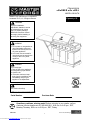 1
1
-
 2
2
-
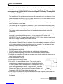 3
3
-
 4
4
-
 5
5
-
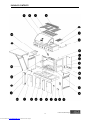 6
6
-
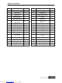 7
7
-
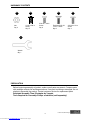 8
8
-
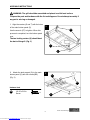 9
9
-
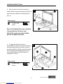 10
10
-
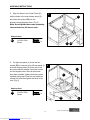 11
11
-
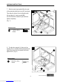 12
12
-
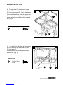 13
13
-
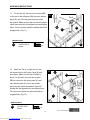 14
14
-
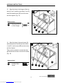 15
15
-
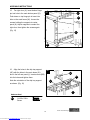 16
16
-
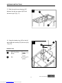 17
17
-
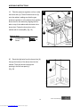 18
18
-
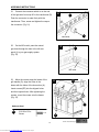 19
19
-
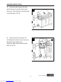 20
20
-
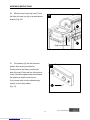 21
21
-
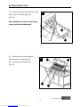 22
22
-
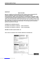 23
23
-
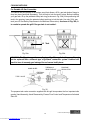 24
24
-
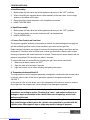 25
25
-
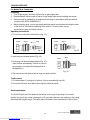 26
26
-
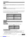 27
27
-
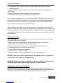 28
28
-
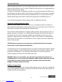 29
29
-
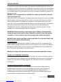 30
30
-
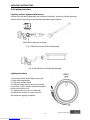 31
31
-
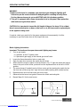 32
32
-
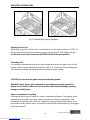 33
33
-
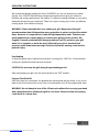 34
34
-
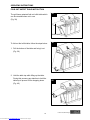 35
35
-
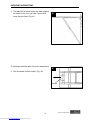 36
36
-
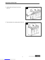 37
37
-
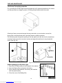 38
38
-
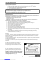 39
39
-
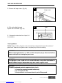 40
40
-
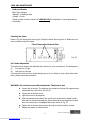 41
41
-
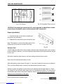 42
42
-
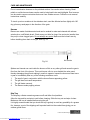 43
43
-
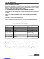 44
44
-
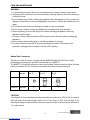 45
45
-
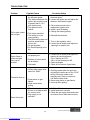 46
46
-
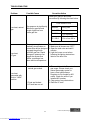 47
47
-
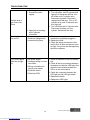 48
48
-
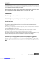 49
49
-
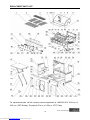 50
50
-
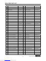 51
51
-
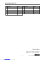 52
52
-
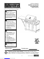 53
53
-
 54
54
-
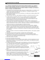 55
55
-
 56
56
-
 57
57
-
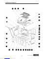 58
58
-
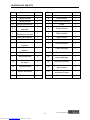 59
59
-
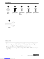 60
60
-
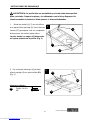 61
61
-
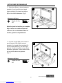 62
62
-
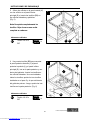 63
63
-
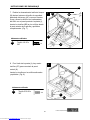 64
64
-
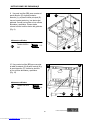 65
65
-
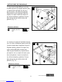 66
66
-
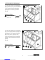 67
67
-
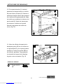 68
68
-
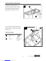 69
69
-
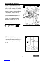 70
70
-
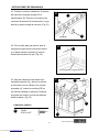 71
71
-
 72
72
-
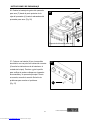 73
73
-
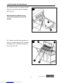 74
74
-
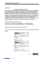 75
75
-
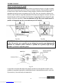 76
76
-
 77
77
-
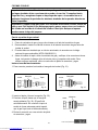 78
78
-
 79
79
-
 80
80
-
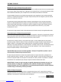 81
81
-
 82
82
-
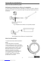 83
83
-
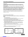 84
84
-
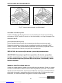 85
85
-
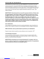 86
86
-
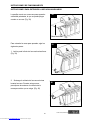 87
87
-
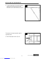 88
88
-
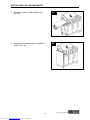 89
89
-
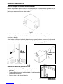 90
90
-
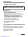 91
91
-
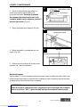 92
92
-
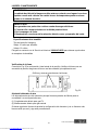 93
93
-
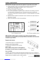 94
94
-
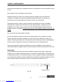 95
95
-
 96
96
-
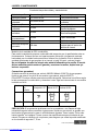 97
97
-
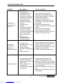 98
98
-
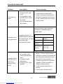 99
99
-
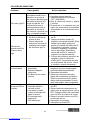 100
100
-
 101
101
-
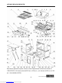 102
102
-
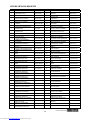 103
103
-
 104
104


Master Forge 3218LTM El manual del propietario
- Categoría
- Barbacoas
- Tipo
- El manual del propietario
En otros idiomas
- English: Master Forge 3218LTM Owner's manual
Documentos relacionados
-
Master Forge 820-0033 El manual del propietario
-
-
-
-
-
-
-
-
-
Otros documentos
-
Browning BR4GRILL El manual del propietario
-
Brinkmann 810-6340-S El manual del propietario
-
-
-
Masterbuilt MB20020413 El manual del propietario
-
KitchenAid 720-0864 El manual del propietario
-
Home Decorators Collection 1305700960 Guía de instalación
-
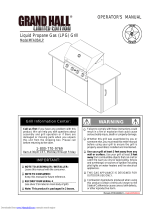 Grand Hall MFA05ALP El manual del propietario
