Master Forge RT2417S El manual del propietario
- Categoría
- Barbacoas
- Tipo
- El manual del propietario

1
Master Forge & M Design
®
is a registered
trademark of LF, LLC. All rights reserved.
Lowes.com/masterforge
ATTACH YOUR RECEIPT HERE
Serial Number _________________________ Purchase Date _________________________
Questions, problems, missing parts? Before returning to your retailer, call our
customer service department at 1-800-963-0211, 8 a.m. - 6 p.m., EST,
Monday - Thursday, 8 a.m. - 5 p.m., EST, Friday.
ITEM #0503231
3-BURNER STAINLESS STEEL GRILL
MODEL #RT2417S
Español p. 39
AB13577
WARNING
Improper installation,
adjustment, alteration, service
or maintenance can cause
injury or property damage.
Read this instruction manual
thoroughly before installing or
servicing this equipment.
WARNING
1. Do not store or use gasoline or
other ammable vapors and
liquids in the vicinity of this or
any other appliance.
2. An LP tank not connected for
use should not be stored in the
vicinity of this or any other
appliance.
DANGER
If you smell gas:
1. Shut off gas to the appliance.
2. Extinguish any open ames.
3. Open the lid.
4. If the odor continues, keep
away from the appliance and
immediately call your gas
supplier or re department.
WARNING
For Outdoor Use Only
GAS-FIRED
C US
MH 10297
Downloaded from www.Manualslib.com manuals search engine

2
Lowes.com/masterforge
TABLE OF CONTENTS
Safety Information . . . . . . . . . . . . . . . . . . . . . . . . . . . . . . . . . . . . . . . . . . 3
Safety Tips . . . . . . . . . . . . . . . . . . . . . . . . . . . . . . . . . . . . . . . . . . . . . . 5
Package Contents . . . . . . . . . . . . . . . . . . . . . . . . . . . . . . . . . . . . . . . . . . 6
Hardware Contents . . . . . . . . . . . . . . . . . . . . . . . . . . . . . . . . . . . . . . . . . . 7
Preparation . . . . . . . . . . . . . . . . . . . . . . . . . . . . . . . . . . . . . . . . . . . . . . 8
Assembly Instructions . . . . . . . . . . . . . . . . . . . . . . . . . . . . . . . . . . . . . . . . 9
Natural Gas Conversion Instructions . . . . . . . . . . . . . . . . . . . . . . . . . . . . . . . 17
Cooking with Gas . . . . . . . . . . . . . . . . . . . . . . . . . . . . . . . . . . . . . . . . . . 19
Operating Instructions . . . . . . . . . . . . . . . . . . . . . . . . . . . . . . . . . . . . . . . 26
Care and Maintenance . . . . . . . . . . . . . . . . . . . . . . . . . . . . . . . . . . . . . . . 30
Troubleshooting . . . . . . . . . . . . . . . . . . . . . . . . . . . . . . . . . . . . . . . . . . 34
Warranty . . . . . . . . . . . . . . . . . . . . . . . . . . . . . . . . . . . . . . . . . . . . . . . 36
Replacement Parts List. . . . . . . . . . . . . . . . . . . . . . . . . . . . . . . . . . . . . . . 37
Downloaded from www.Manualslib.com manuals search engine

3
Lowes.com/masterforge
SAFETY INFORMATION
Please read and understand this entire manual before attempting to assemble, operate
or install the product. If you have any questions regarding the product, please call
customer service at 1-800-963-0211, 8:00 am to 6:00 pm, EST, Monday- Thursday, 8:00
a.m. to 5:00 p.m., EST, Friday.
1. The installation of this appliance must conform with local codes or, in the absence of local
codes, with either the National Fuel Gas Code, ANSI Z223.1/NFPA 54, or Natural Gas
and Propane Installation Code, CSA/CGA-B149.1.
2. This grill is intended for use outdoors and should not be used in a building, garage or any
other enclosed or covered area.
3. This outdoor grill is not intended for installation in or on recreational vehicles and/or boats.
4. A minimum clearance of 36 in. from combustible constructions to the sides of the grill and
36 in. from the back of the grill to combustible constructions must be maintained. This
outdoor cooking gas appliance must not be placed under overhead combustible
construction.
5. The use of an electrical source requires that when installed, the grill must be electrically
grounded in accordance with local codes or, in the absence of local codes, with
ANSI/NFPA 70, or the Canadian Electrical Code, CSA C22.1. Keep electrical supply cords
and the fuel supply hose away from heated surfaces.
6. Inspect the hoses before each use for excessive abrasion or wear, or cuts that may affect
safe operation of the grill. If there is evidence of excessive abrasion or wear, or the hose is
cut, it must be replaced prior to the grill being put into operation. The replacement hose
assembly must be those specied by the manufacturer.
7. Keep your grill in an area clear and free from combustible materials, gasoline and other
ammable vapors and liquids.
8. DO NOT obstruct the ow of combustion and ventilation air to this appliance.
9. Keep the ventilation openings of the tank enclosure free and clear from debris.
10. Check all gas connections for leaks with a soapy water solution and brush. Never use an
open ame to check for leaks.
11. Never use charcoal in the grill.
12. Never use the grill in windy areas.
13. Only a 20 lb. LP-gas cylinder is allowed. The cylinder must be
constructed and marked in accordance with the Specications for
LP Gas Cylinders of the U.S. Department of Transportation (D.O.T.)
or the National Standard of Canada, CAN/CSA-B339, Cylinders,
Spheres and Tubes for Transportation of Dangerous Goods; and
Commission. A 20 lb LP-Gas cylinder’s dimensions are:
14. Never use the grill without the drip tray installed and pushed completely into the back of
the grill. Without the drip tray, hot grease and debris could leak downward and produce a
re hazard.
18 in
13.9 in
8 in
12.2 in
Downloaded from www.Manualslib.com manuals search engine

4
Lowes.com/masterforge
SAFETY INFORMATION
15. The pressure regulator for LP-gas grill is set for 11-in. water column (WC). Natural gas
grill provides a hose assembly which includes a quick-disconnect device, but no pressure
regulator. The LP pressure regulator or the natural gas hose assembly must be used.
Replacement pressure regulators and hose assemblies must be those specied in the
parts list.
16. The cylinder used must include a collar to protect the cylinder valve.
17. Do not store a spare LP-gas cylinder under or near this appliance.
18. Never ll the cylinder beyond 80 percent full.
19. If the information in “17” and “18” is not followed exactly, a re
causing death or serious injury may occur.
20. The natural gas grill and its individual shutoff valve must be disconnected from the gas
supply piping system during any pressure testing of that system at test pressures in
excess of 0.5 PSI (3.5 kPa).
21. The outdoor cooking gas appliance must be isolated from the gas supply piping system
by closing its individual manual shutoff valve during any pressure testing of the gas supply
system at test pressures equal to or less than 1/2 PSI (3.5 kPa).
22. CALIFORNIA PROPOSITION 65 WARNING: The burning of gas cooking fuel generates
some byproducts which are on the list of substances known by the state of California to
cause cancer, reproductive harm, or other birth defects. To reduce exposure to these
substances, always operate this unit according to the use and care manual, ensuring you
provide good ventilation when cooking with gas.
IMPORTANT: We urge you to read this manual carefully and follow the recommendations
enclosed. This will ensure you receive the most enjoyable and trouble-free operation of your
new gas grill. We also advise you retain this manual for future reference.
WARNING: Your grill has been designed to operate using only the gas specied by the
manufacturer on the rating plate. Do not attempt to operate your grill with other gases. Failure
to follow this warning could lead to a re hazard and bodily harm and will void your warranty.
WARNING: Make certain your LP (propane) tank is lled by a reputable propane dealer. An
incorrectly lled or an overlled LP tank can be dangerous. The overlled condition combined
with the warming of the LP tank (a hot summer day, tank left in the sun, etc.) can cause LP
gas to be released by the pressure relief valve on the tank since the temperature increase
causes the propane to expand. LP gas released from the tank is ammable and can be
explosive. Refer to your Owner’s Manual for more information concerning lling your LP tank.
This unit contains one or more patents pending:
61/163,753
61/215,319
11/495,104
11/268,051
Downloaded from www.Manualslib.com manuals search engine

5
Lowes.com/masterforge
SAFETY TIPS
● Never pull your grill. Always push it.
● Never move your grill while it is in operation or still hot.
● Always use a protected hand when cleaning the grid surface after the post-heating period an
when closing the propane tank valve.
● Use a covered hand during the grilling period.
● Wait until the burner box has completely cooled before reaching under to turn off the gas
● Using an uncovered hand to turn off the LP tank valve without allowing the grill to cool down
could result in severe burns.
● Never operate your grill under overhangs, awnings or any covered or enclosed area.
● Never spray liquid on the grid area to control are ups.
● To guard against possible grease res getting out of control, never leave a grill unattended.
● Grease res can be severe and cause grill damage, property damage and bodily harm.
● Always turn off the control knob rst, then the propane gas supply tank.
● Never cover your grill while it is still warm.
● Position your portable grill away from direct wind.
● Do not store or use gasoline or other ammable substances in the vicinity of your gas grill.
● Never store a propane tank (whether full or empty) inside your home or living area.
● Before storing your tank, make sure that it has been turned to the “OFF” position.
● Should you store your grill indoors, be sure to close the tank valve, disconnect the hose from
the tank, remove the tank from the grill and store the tank outdoors.
● Make sure the grill hood is completely open before lighting your grill.
● When connecting or replacing any gas ttings, all joints must be sealed with an approved,
leak-proof sealing compound.
● Never use an open ame to test for gas leaks.
● When your grill is not in use, it is recommended that for child safety, you remove the control
knobs and store them indoors.
● Keep children away from the grill at all times.
● Never drill out any orice or make any eld alterations to your grill without receiving approval
from the manufacturer.
● Do not store ammable materials in any of the cabinets beneath the grill burner box or in the
vicinity of your grill.
● Be careful while handling any parts during assembly. It is strongly recommended that you
protect your hands with a pair of work gloves.
● At high temperatures, some stainless grids may discolor over time. When the grill is cool,
wiping with a towel and vegetable oil may remove and treat some of this effect. Some
discoloration is normal.
Downloaded from www.Manualslib.com manuals search engine


7
Lowes.com/masterforge
PACKAGE CONTENTS
PART DESCRIPTION QUANTITY
A Burner Box 1
B Heat Tent 3
C Main Grid 2
D Warming Rack 1
E
Right Side Shelf
Bracket
2
F Right Side Shelf 1
G Left Side Shelf 1
H
Left Side Shelf
Bracket
2
I Drip Tray Support 1
J Safety Tank Ring 1
K Tank Ring Bracket 1
PART DESCRIPTION QUANTITY
L Rear Panel 1
M Igniter 1
N Right Panel 1
O Drip Tray 1
P Bottom Panel 1
Q Locking Caster 2
R Caster 2
S Door 1
T Left Panel 1
U Front Beam 1
Downloaded from www.Manualslib.com manuals search engine

8
Lowes.com/masterforge
HARDWARE CONTENTS
AA
BB
CC
3/16-24 x 1/2 in.
Screw
qty. 49
1/4-20 x 5/8 in.
Screw
qty. 2
AA Battery
qty. 1
PREPARATION
Before beginning assembly of product, make sure all parts are present. Compare parts
with package contents list and hardware contents list. If any part is missing or damaged,
do not attempt to assemble the product.
Estimated Assembly Time: 30 minutes by 2 people
Tools Required for Assembly: Phillips screwdriver (sold separately)
Downloaded from www.Manualslib.com manuals search engine

9
Lowes.com/masterforge
ASSEMBLY INSTRUCTIONS
WARNING: The grill should be assembled and placed on a at, level suface.
Compare the parts and hardware with the list and diagrams. Do not attempt assembly if
any part is missing or damaged.
1. Attach the locking casters (Q) and the
casters (R) to the bottom panel (P)
using 12 screws (AA). When this process
is completed, turn the bottom panel over.
The two locking casters (Q) should be
at the back of the grill.
2. Align the holes in the rear panel (L)
with the holes in the bottom panel (P)
and insert screws (AA) into the aligned
holes.
Note: Do not tighten the screws
completely. Leave at least one full turn
on each. After all the screws have been
installed, go back and tighten them fully.
Hardware Used
Hardware Used
AA
3/16-24 x 1/2 in.
Screw
x 12
AA
AA
3/16-24 x 1/2 in.
Screw
x 3
1
AA
Q
P
R
2
P
L
Downloaded from www.Manualslib.com manuals search engine

10
Lowes.com/masterforge
ASSEMBLY INSTRUCTIONS
3. Attach the left panel (T) and right panel (N) to
the bottom panel (P). For both the left and
right panels, there are three screws for the
rear panel (L) and four for the bottom panel.
Insert the four bottom panel screws rst.
Hardware Used
AA
3/16-24 x 1/2 in.
Screw
x 14
4. Attach the front beam (U) to the left panel (T)
and the right panel (N) with 2 screws (AA)
on each side as shown.
Hardware Used
AA
3/16-24 x 1/2 in.
Screw
x 4
3
AA
L
N
P
T
AA
U
4
Downloaded from www.Manualslib.com manuals search engine

11
Lowes.com/masterforge
ASSEMBLY INSTRUCTIONS
5. Slide the tank ring bracket (K) onto the end
of the safety tank ring (J) as shown. Attach
the tank ring bracket to the rear panel (L)
with 2 screws (BB) as shown.
6. Attach the drip tray support (I) to the front
beam (U) and rear panel (L) with 4 screws
(AA) as shown.
7. Remove the cap and the nut from the igniter
(M). Secure the igniter to the right panel (N)
with the nut. Then, reassemble the cap to
the igniter.
Hardware Used
AA
3/16-24 x 1/2 in.
Screw
x 4
Hardware Used
1/4 - 20x 5/8 in.
Screw
x 2
5
BB
BB
K
J
6
AA
U
I
7
Nut Cap
M
Downloaded from www.Manualslib.com manuals search engine

12
Lowes.com/masterforge
ASSEMBLY INSTRUCTIONS
8. For the door (S), insert bottom hinge pin into
hole on bottom panel (P). Push top hinge
pin in the corner of the door to insert into
hole in top corner of the right panel (N).
Then, put the drip tray (O) onto the drip tray
support (I).
9. Take the pressure regulator out from under
the burner box (A). Lift the burner box (A)
onto the cabinet, making sure that the gas
pressure regulator is in the cabinet, then
position burner box on the cabinet by
aligning the four tabs on top of the cabinet
with the holes in the burner box. Fasten the
burner box to the cabinet with 4 screws (AA).
Hardware Used
AA
3/16-24 x 1/2 in.
Screw
x 4
8
9
S
N
I
O
AA
Tab
Pressure
regulator
A
Downloaded from www.Manualslib.com manuals search engine

13
Lowes.com/masterforge
ASSEMBLY INSTRUCTIONS
10. Attach the left side shelf bracket (H) to the
left of the burner box (A) and the right side
shelf bracket (E) to the right of the burner
box with 2 screws (AA) on each bracket.
Hardware Used
AA
AA
3/16-24 x 1/2 in.
Screw
x 8
Complete Steps 11 - 13 to complete assembly
of the left side shelf (G) and right side shelf (F).
11. Move the side shelves from front to back,
making sure the screw on the side shelf
brackets t inside the holes on the side
shelves.
10
H
H
E
E
11
G
F
Side shelf
bracket
Side shelf
Downloaded from www.Manualslib.com manuals search engine

14
Lowes.com/masterforge
ASSEMBLY INSTRUCTIONS
12. Hang the side shelves on the brackets
and slowly rotate the side shelves.
13. Adjust the side shelves until they are
aligned with the control box.
14. Plug the main burner igniter wires into
the sockets in the igniter.
12
13
14
G
G
F
F
Control box
Igniter wires
Downloaded from www.Manualslib.com manuals search engine

15
Lowes.com/masterforge
ASSEMBLY INSTRUCTIONS
15. Place the heat tents (B), main grids
(C) and warming rack (D) into the
burner box (A). Remove the battery
cap on the igniter (M) and insert a AA
battery (CC) with the positive end
facing outward. Replace the cap.
B
C
D
Insert
AA battery
15
Downloaded from www.Manualslib.com manuals search engine

16
Lowes.com/masterforge
ASSEMBLY INSTRUCTIONS
IMPORTANT
CHECK SPARKS
After you complete your grill assembly, test your ignition system with the GAS OFF.
Check for continuous sparks when pushing in the knob ignition system.
For the side burner, sparks can be seen directly. For main burners, the ignition system
is positioned next to each burner inside the burner box. A reection of sparks or sparks
can be seen at the front of the inside of the burner box, or you can place a mirror on the
left of each main burner and see the sparks and hear the click of the igniters. Be sure the
GAS IS OFF when you push in the control knobs. This will help assure a trouble-free
ignition when you turn on the gas.
ASSEMBLED GRILL DIMENSION (INCHES):
46 (HEIGHT) x 51.2 (WIDTH) x 22.3 (DEPTH) (SIDE SHELF FOLDED OUT)
46 (HEIGHT) x 32 (WIDTH) x 22.3 (DEPTH) (SIDE SHELF FOLDED DOWN)
WARMING RACK AREA (SQUARE INCHES): 142
THE UL LABEL IS ON THE BACK OF THE DOOR, SHOWN AS PICTURED BELOW.
31EV
MH10297
31EV
MH10297
(a) Do not store a spare LP-Gas cylinder under or near this appliance.
(b) Never fill the cylinder beyond 80 percent full.
(c) If the information in “(a)” and “(b)” is not followed exactly, a fire causing death or serious injury may occur.
MADE IN CHINA
CON CERTIFICACIÓN ANS Z21.58a-CSA 1.6a-
2008. ELECTRODOMÉSTICOS DE COCINA A
GAS PARA EXTERIORES.
PARA USO EN EXTERIORES SOLAMENTE. SI
GUARDA LA UNIDAD EN EL INTERIOR,
RETIRE EL TANQUE Y DÉJELO EN EL
EXTERIOR.
L G Sourcing Inc.
P.O.Box 1535 North Wilkesboro,
NC, 28659 USA
Modelo No. RT2417S
Tipo de gas: propano (Convertible a
Gas Natural)
Entrada: Quemador principal:
3x12,000 BTU/h
Debe haber un espacio de separación mínimo de 91,44 cm desde los lados
y la parte posterior de la unidad hasta construcciones de material
combustible.
No use este electrodoméstico debajo de superficies combustibles.
Este electrodoméstico de cocina a gas para exteriores no está diseñado
para instalarse en vehículos recreativos ni en botes.
(a) No almacene un tanque de gas propano de reserva debajo o cerca de este aparato.
(b) Nunca llene el tanque a más del 80% de su capacidad.
(c) Si no sigue con precisión la información en “(a)” y “(b)”, puede provocar un incendio que produzca lesiones
graves o la muerte. HECHO EN CHINA
Date de fabrication : XX N° de série : RT000001
L G Sourcing Inc.
P.O.Box 1535 North Wilkesboro,
NC, 28659 USA
Model No.: RT2417S
Type of Gas:Propane(Convertable to
Natural Gas)
Input: Main Burner: 3x12,000 BTU/Hr
Minimum clearance from sides and back of unit to combustible construction,
36 inches from sides and 36 inches from back.
Do not use this appliance under overhead combustible surfaces.
This outdoor cooking gas appliance is not intended to be installed in or on
recreational vehicles and / or boats.
Manufacturing Date: XX Serial No.: RT000001
CERTIFIED UNDER ANS Z21.58a-CSA 1.6a-
2008. OUTDOOR COOKING GAS APPLIANCES.
FOR OUTDOOR USE ONLY. IF STORED
INDOORS, DETACH AND LEAVE CYLINDER
OUTDOORS.
GAS-FIRED
C US
GAS-FIRED
C US
Downloaded from www.Manualslib.com manuals search engine

17
Lowes.com/masterforge
NATURAL GAS CONVERSION INSTRUCTIONS
Should you decide to convert your gas grill
from liquid propane gas to natural gas,
use NG Conversion Kit Item #0050772.
The #0050772 kit contains orices for various grill
models. Please select the orices as listed and
discard the rest. Follow the conversion instruction
provided with the kit.
Main Burner Conversion
16. Pull off the R-pins and take the main
burners out. Adjust main burners’ air shutters
by loosening the air shutter screws.
17. The settings are:
1/4 in. open for LP gas.
1/16 in. - 1/8 in. open for NG gas.
You need to adjust the openings before you
put the burners back in the burner box.
Model Item number Main burner
Φ1.37
RT2417S 0503231 3
R-pin Main burner
16
17
Air shutter
Downloaded from www.Manualslib.com manuals search engine

18
Lowes.com/masterforge
18. Remove the LP orices rst with the orice
removal tool, then install the NG orice. Make
sure you are using the correct orice, marked
“1.37”.
When this step completed, install the main
burners back to the rebox and secure to the
bracket with the R-pins.
Make sure the orices are aligned with the
burners and the ignition pins are installed
in their original positions. Check the sparks
before operating the grill.
Change to 10 ft. NG hose
19. Take the regulator off from the manifold and
replace it with 10-ft. natural gas hose. Please
make sure the hose is securely fastened.
Adjust valve control screw
20. Pull all the knobs off from valve stems. Adjust
the screw in the valve hole using the athead
screwdriver. Turn screws two complete turns
counterclockwise.
21. To complete conversion, re-install all knobs,
return heat diffusers to rebox, followed by the
grates and warming rack.
NATURAL GAS CONVERSION INSTRUCTIONS
18
1.37
19
20
Valve hole
Downloaded from www.Manualslib.com manuals search engine

19
Lowes.com/masterforge
COOKING WITH GAS
For Portable LP-Gas Connection
The cabinet has an opening in the bottom panel that allows a 20 lb. gas tank bottom ange to
drop into place (tank sold separately). This will help to lock the tank in place. Before installing
your gas tank, lift up the safety tank ring (as shown in Fig. 21a). After positioning the tank in
the opening, lower the safety tank ring to lock the tank in place. Use only a 20 lb. gas tank
(see LP Gas Safety Requirements for Additional Information). As shown in Fig. 21b, it is
unsafe to operate the grill if the gas tank is not vertical.
LP Tank
Fig. 21a Fig. 21b
WARNING: The Type I connective coupling (see Fig. 22) supplied with your grill must
not be replaced with a different type of grill/tank connection system. Removal will
result in loss of warranty, gas leakage, re and severe bodily harm.
HAND WHEEL
TYPE I VALVE
EXTERNAL
THREAD
THERMALLY
SENSITIVE NUT
PROPANE
REGULATOR
The propane tank valve connection supplied with this grill incorporates four important safe guards:
Hand Assembly, Hand Disassembly, Excess Flow Control and Temperature-Activated Shut-Off.
Fig. 22
Downloaded from www.Manualslib.com manuals search engine

20
Lowes.com/masterforge
COOKING WITH GAS
a. Hand Assembly:
1. Make certain the tank valve and all the appliance valves are in the “OFF” position.
2. When connecting the regulator/burner valve assembly to the tank valve, turn the large plastic
nut clockwise until it stops.
3. Gas will not ow unless the plastic nut is completely connected.
4. HAND TIGHTEN ONLY.
b. Hand Disassembly:
1. Make certain the tank valve and all the appliance valves are in the “OFF” position.
2. Turn the large plastic nut counterclockwise until it is disassembled.
3. HAND LOOSEN ONLY.
c. Excess Flow Control and Low Heat:
The propane regulator assembly incorporates an excess ow device designed to supply the
grill with sufcient gas ow under normal conditions yet control excess gas ow.
Rapid changes in pressure can trigger the excess ow device providing a low ame and low
temperature. If the tank valve is turned open to allow gas ow while a burner valve is open,
the surge of pressure will cause the device to activate. The device will remain closed until the
pressure is equalized. This should occur within 5 seconds.
To ensure this does not cause difculty in lighting the grill, follow these instructions:
1. Make sure all burner valves are “OFF”.
2. Open the tank valve and wait 5 seconds.
3. Light the burners one at a time following the lighting instructions.
d. Temperature-Activated Shut-Off:
The large plastic nut on the regulator assembly is designed in coordination with a check valve
in the tank valve to shut off the ow of gas when exposed to temperatures between
240-300° F.
In the event of a re or hose break, one of the safeguards will function to control or stop the
ow of gas from the propane tank. Never attempt to use damaged equipment.
Important: Before the use of a fresh tank of gas, please check leakage around the
connections according to section ‘Checking Gas Leaks’ and make sure there is no
leakage or vapor accumulation in the cabinet. Make sure all openings around side
walls are not blocked.
Important: Place dust cap on cylinder valve outlet whenever the cylinder is not in use.
Only install the type of dust cap on the cylinder valve outlet that is provided with the
cylinder valve. Other types of caps or plugs may result in leakage of propane.
Downloaded from www.Manualslib.com manuals search engine

21
Lowes.com/masterforge
COOKING WITH GAS
For Natural Gas Connection
Preparing:
1. Turn off gas supply and then remove cap on gas supply side.
2. Recommended: Install a shut-off valve on gas supply side before installing the socket.
3. Socket should be installed by an authorized technician in accordance with the national fuel gas
code (NFPA 54/ANSI223.1).
4. Before inserting plug, turn on gas supply and leak test all connections including the stem of the
shut-off valve and the opening of the socket. For best results, use an ammonia-free soap and
water solution.
Operating Instructions:
1. To connect, push back socket sleeve (Fig. 23).
2. Insert plug and release sleeve (Fig. 24).
3. Push plug until sleeve snaps forward (Fig. 25).
(Gas will ow automatically. Failure to connect
plug properly to socket will inhibit gas ow to
the appliance.)
4. Test connection with ammonia-free soap and water solution.
To disconnect:
1. Pull sleeve back. Pull plug out of socket. (Gas is automatically shut off.)
2. Close shut-off valve and replace dust caps on socket and plug.
Gas Requirements:
The RT2417S grill is set and tested at the factory for the type of gas supply to be used.
Identify the type of gas, either natural gas or LP gas, and make sure the marking on the rating
plate matches the gas supply. The rating plate is located on the inside panel of the door.
Socket
Sleeve
Plug
Fig. 23 Fig. 24
SleeveSocket
Sleeve
Socket
Fig. 25
Downloaded from www.Manualslib.com manuals search engine

22
Lowes.com/masterforge
COOKING WITH GAS
LP Gas
If your grill is for LP gas, the regulator supplied is set for an 11-in. water column (WC) and is
for use with LP gas only. The factory-supplied regulator and hose must be used with a 20-lb.
LP gas tank.
Natural Gas
Your grill is natural gas convertible. NG kit sold separately (Item #0050772). Please follow the
manual to convert your grill to natural gas.
If your grill is for natural gas, it is set for a 7-in. water column (WC) and is for use with natural
gas only. Gas pressure is affected by gas line size and the length of gas line run from the
house gas line. Follow the recommendations in the chart below.
From House to Grill
Distance Tubing Size
Up to 25 ft. 3/8 in. DIA
26-50 ft. 1/2 in. DIA
51-100 ft.
2/3 in. of run - 3./4 in.
1/3 in. of run - 1/2 in
More than 101 ft. 3/4 in. DIA
LP GAS System
Contact your gas supplier for a special regulator for bulk gas that fuels other
appliances.
Gas Consumption
Total gas consumption of this grill with the burner(s) on “HIGH”: Table 1 below.
Table 1
Burner Type BTU/HR
Main Burners 12,000 x 3
LP Gas Safety Requirement
For LP gas grills, the LP gas supply tank to be used must be:
(a) Constructed and marked in accordance with the Specications for LP Gas Tanks of the
U.S. Department of Transportation (DOT) or the National Standard of Canada,
CAN/CSA-B339 Cylinders, Spheres and Tubes for Transportation of Dangerous Goods;
and Commission, as applicable.
(b) Provided with a listed Overll Prevention Device (OPD).
Downloaded from www.Manualslib.com manuals search engine

23
Lowes.com/masterforge
COOKING WITH GAS
(c) Provided with a tank connection device compatible with the connection for outdoor
cooking appliances.
The tank should be 12 in. in diameter and 18-1/2 in. tall and be equipped with a Type-1 tting.
The tank supply system must be arranged for vapor withdrawal.
The tank used must include a collar to protect the cylinder valve.
Do not operate the gas grill indoors or in any enclosed area. If the gas grill is not in use, the
gas must be turned off at the supply tank. If the grill is to be stored indoors, disconnect the
gas supply tank and store the tank in an upright position in a cool, well-ventilated outdoor
location away from your grill or any other heat source.
When checking for gas leaks, do not use an open ame. Use a soapy water solution and
apply it to the pipe joints and ttings with a brush and check for bubbles. Check exible hoses
for cuts and wear that may affect the safe operation of the grill. Only the factory supplied hose
and regulator must be used. Use only replacement regulator and hose assemblies specied
by manufacturer.
Checking Gas Leaks
Before operating your grill, after refueling, check carefully to be certain that all connections
are tight and there are no gas leaks.
1. Make 2-3 ounces of leak solution by mixing liquid dishwashing soap with water.
2. Make certain all control knobs are in the “OFF” position.
3. Brush small amounts of the leak solution on all the ttings and turn the gas on.
4. If bubbles appear, there is a leak. Proceed to step 5.
5. Turn the gas off and tighten all connections.
6. Go back to step 1 to retest the ttings.
7. If bubbles continue to appear, turn the gas off. Contact customer service.
WARNING: Never use a match or open ame for leak detection. Use of an open ame
could result in a re, explosion and bodily harm.
IMPORTANT: When connecting or replacing any gas pipe or ttings, all joints must be
sealed with approved leak-proof sealing compound or plumber’s tape.
Handling the Liquid Propane Tank Safely
Remember to handle your portable liquid propane tank carefully when you take it to your
dealer for a rell. Avoid dropping it or bumping it against sharp objects. Liquid propane tanks
are sturdily constructed, but a series of hard jolts could damage the container.
Downloaded from www.Manualslib.com manuals search engine

24
Lowes.com/masterforge
COOKING WITH GAS
When transporting the tank to your local propane gas dealer, make sure the valve is closed
tightly and the protective cover is in place. Position the tank securely in an upright position so
it will not roll around your vehicle.
If you plan to make stops for shopping or errands, have your liquid propane tank lled at the
last stop before going home. Again, make certain the relled tank is secure and in an upright
position. When you return home, remove the relled tank from your vehicle. Never leave a
portable liquid propane tank inside a vehicle that may become overheated by the sun.
Your local liquid propane gas dealer will gladly offer you additional safety tips.
Storing the Liquid Propane Tank Safely
Whether you are between cross-country treks in your recreational vehicle or looking for a
place to keep the liquid propane tank to provide fuel for your outdoor grill, keep in mind some
basic safety rules about storing portable liquid propane tanks:
Do not store the tanks (whether full or empty) inside your home, the living area of an R.V., a
garage, basement or workshop. It is unlikely that liquid propane will leak from the tanks. If it
should leak, the fuel could be exposed to sparks from automobiles, power tools or other
appliances. When storing or transporting your LP tank, it must remain in an upright position.
Never lay your LP tank down on its side whether it is full or empty. Never store a spare tank
under or near your grill.
CAUTION: Never transport or move your grill or grill tank without rst closing the
manual valve on your liquid propane gas tank.
The best place to store a liquid propane tank is in a shady or protected spot outdoors, behind
your home or garage, or on a screened porch but where it is out of reach of children. Liquid
propane will not evaporate. It is in a strong, closed container. It will not lose any of its
clean-burning heat content, even if left outside year-round.
WARNING: When not connected to your grill, the LP gas tank must be stored in an
upright position in a cool, shady, well-ventilated, outdoor location away from your grill
or any other heat source. Failure to follow this warning could lead to tank valve
damage, re hazard and personal injury.
Relling a Propane Tank
It is extremely important that your LP tank be lled properly when you take it to be relled. Be
sure to use a reputable LP dealer and observe how the tank is lled and at what capacity. An
overlled LP tank can be dangerous.
Downloaded from www.Manualslib.com manuals search engine

25
Lowes.com/masterforge
COOKING WITH GAS
The proper way to ll a tank is by weight. The empty tank should be placed on a scale. The
scale weights should be readjusted to a weight that would allow up to 80% of the total weight.
The lling operation must end once the tank is lled to 80% of its total capacity. If the tank is
not completely empty, the scale readjustment must be changed to consider the propane (LP)
already in the tank.
WARNING: An LP (propane) tank is overlled if it contains more than 80% of its total
capacity of propane (LP).
An incorrectly lled or an overlled LP (propane) tank can be dangerous. If a tank is overlled
and the weather causes the warming of the LP tank, (a hot day, tank left in sun or stored
indoors) internal pressure is created due to expansion of the propane which in turn may
cause the LP gas to be released through the pressure relief valve on the tank. The pressure
relief valve is a safety device required on 20 lb. propane tanks by the Department of
Transportation to prevent a catastrophic tank failure due to excessive pressure. LP gas
released from the tank is ammable and can be explosive.
IMPORTANT: When connecting or replacing gas pipe or ttings, all joints must be
sealed with approved leak-proof sealing compound or plumber’s tape. After making
connections, check all joints for leaks using a soapy water solution and a brush.
WARNING: Never use an open ame to test for gas leaks. Use of an open ame could
result in a re, explosion and bodily harm.
Locating the Grill
This gas appliance is designed and certied for outdoor use only. Do not operate the grill
inside a building, garage, recreation vehicle, screened porch or any enclosed area. Keep the
grill away from windy areas, but keep the grill in a well-ventilated area. Do not obstruct the
ow of combustion and ventilation air around the grill.
Warning: Do not place the grill under overhead, unprotected combustible surfaces.
Clearance to Combustible Construction
A minimum clearance of 36 in. from the sides of the grill and a minimum clearance of 36 in.
from the back of the grill to adjacent vertical combustible constructions must be maintained.
However, the manufacturer strongly suggests a 6 ft. clearance of the grill to combustible
constructions.
Clearance to Noncombustible Construction
A minimum clearance of 36 in. from the back of the grill above the cooking surface to
noncombustible constructions is required to allow the grill hood to open completely. A
minimum of 36 in. clearance to the sides of the grill above the cooking surface to
noncombustible constructions is recommended. The grill can be installed directly next to
noncombustible construction below the cooking surface.
Downloaded from www.Manualslib.com manuals search engine

26
Lowes.com/masterforge
COOKING WITH GAS
Grill Lighting Instructions
Checking orices’ alignment with burners
Orices may shift during assembly and movement; therefore, check the orices’ alignment
with the burners according to the following illustrations before lighting.
Orice stud inside the air shutter
Fig. 26 Main Burner and Orice Relationship
Lighting Instructions
1. Read instructions before lighting your grill.
2. Open lid during lighting.
3. Fully open cylinder valve.
4. Push the control knob in and turn the knob to
the left to “HIGH” position. Keep pressing the
knob until the burner is lit.
5. If ignition does not occur in 5 seconds, turn
the burner control off, wait 5 minutes, and
repeat the lighting procedure.
Fig. 27
GRILL
OFF
LOW
HIGH
Downloaded from www.Manualslib.com manuals search engine

27
Lowes.com/masterforge
OPPERATING INSTRUCTIONS
WARNING:
1. Make sure the hood is completely open each time you attempt to light the grill.
Failure to open the hood could lead to delayed ignition resulting in bodily harm.
2. This grill is equipped with a ame-observation hole in the side panel. Wear
protective mitts before using the ame watch.
CAUTION: It is important to inspect the full length of the gas line hose. If it is evident
there is excessive abrasion or wear, or the hose is cut, the hose must be replaced prior
to the appliance being used.
If required, check your parts list for the proper replacement hose assembly. It will be
necessary to open the bottom door to fully inspect the hose.
Match Lighting Instructions
Important: The hood must be open when match lighting any burner.
1. Turn on gas supply.
a. If portable, at the LP cylinder valve.
b. If permanent gas supply, at the manual gas shutoff valve.
2. Locate the ame observation holes on each side.
3. Open the right door to access the match clip with chain.
4. Attach either the match or paper to the clip shown in Fig. 28, light the match and insert it
close to the ports of the burner, push and turn the depressed knob to the left to “HIGH”
position.
5. The center burner (if needed) can be lit from center grid by inserting the match clip into
the front side of avor step tent. Light this burner before igniting both outside burners.
6. Depress burner valve for that burner and turn to high.
7. Observe that the burner has ignited. Remove the match and extinguish.
8. Repeat Steps 2-6 for the next burner.
Match
Paper
Downloaded from www.Manualslib.com manuals search engine

28
Lowes.com/masterforge
OPPERATING INSTRUCTIONS
Fig. 28 Match/Paper Lighting Illustration
Breaking in Your Grill
When ring your grill for the rst time, it is advisable to run the main burner(s) on “HIGH” for
20 minutes with the hood down and then turn the main burners off. This tempers the grill.
Preheating Grill
It is extremely important that your grill be up to temperature before you begin using it. After
lighting, close the hood and preheat the grill on “HIGH” for 15 minutes. This preheating will
ensure that the cooking grid and grate are hot enough for proper grilling.
CAUTION: Do not cover the grids during the preheating period.
WARNING: Never leave a grill unattended to guard against possible grease res
getting out of control. Grease res can be severe and cause grill damage, property
damage and bodily harm.
Open or closed hood for grilling
Cooking with the lid open or closed is a matter of personal preference. Cooking with the lid
closed is recommended if you enjoy cooking at maximum “searing” temperatures. This
method will also produce more “are up”, speed the cooking procedure and will give you a
more robust, smoky, outdoor avor. If you prefer cooking slower with less are up, we suggest
the lid-open method.
Downloaded from www.Manualslib.com manuals search engine

29
Lowes.com/masterforge
OPPERATING INSTRUCTIONS
We recommend always cooking with the lid CLOSED if you are in a windy area or colder
climate. Your grill has been designed and constructed to give you maximum exibility and
cooking performance. Be creative. Try different cooking methods on your grill to determine
which suits your needs best. There is no right or wrong way to cook, just different cooking
styles. Get creative and enjoy!
WARNING: Please remember this is an outdoor gas grill. Many areas of the grill
generate extreme heat. We have taken every precaution to protect you from the contact
areas. However, it is impossible to isolate all high-temperature areas. Therefore, use
good judgment and a certain degree of caution when grilling on this product. We
suggest a covered, protected hand during operation of grill. Do not move your grill
when it is in operation or hot to the touch. Wait until your unit is turned off and
properly cooled down before moving it. Failure to follow this warning could result in
personal injury.
Post Heating
To keep the grates free of charred food remains, run the grill on “HIGH” for 15 minutes after
cooking is complete and food has been removed.
CAUTION: Do not cover the grill during the post heating period.
After post heating your grill, turn the control knobs to the “OFF” position.
Propane Tank Shut-Off
After the burner box cools down, the propane tank valve should also be closed. If you do not
want to wait for the burner box to cool, use a covered hand to turn off the propane tank valve.
WARNING: Do not attempt to turn off the LP tank valve without rst covering your hand
with a protective mitt or allowing the grill to cool down. Failure to follow this warning
could result in a severe burn.
Downloaded from www.Manualslib.com manuals search engine

30
Lowes.com/masterforge
CARE AND MAINTENANCE
Checking the Flame
Refer to Fig. 29 below (side view of grill). Check the ame after the grill is lit. Make sure you
have a stable, mostly blue ame.
Flame Observation Hole
Fig. 29
Air Shutter Adjustment
The main burner shutters are adjusted at the factory for your convenience. The settings are:
(1) Full open for LP gas.
(2) Half open for NG gas.
If you desire to ne tune your shutter adjustment (or if your ame is more yellow rather than
blue), please follow this procedure.
WARNING: Do not touch burner after adjustments. The burner is hot.
a. Loosen the air shutter. The shutters are located on the end of the gas burners underneath the
control box. See Fig. 30
b. Loosen the air shutter screw.
c. Light the burner to be adjusted.
d. With a protected gloved hand, ne tune the air shutter until a stable, mostly blue ame is observed
through the ame observation hole and slots on each side of the burner box. Acceptable ames
are shown in Fig. 31
e. Tighten the air shutter locking screw enough to hole the shutter in place.
f. Repeat procedure on other burners.
(a)
(b)
(c)
Fig. 30 Air Shutter Fig. 31 Acceptable Flame (only a)
Air Shutter
√
×
×
Downloaded from www.Manualslib.com manuals search engine

31
Lowes.com/masterforge
CARE AND MAINTENANCE
CAUTION: If the natural gas conversion kit is used, remember to adjust the air shutter
of main burner (for details, please read the NG conversion kit manual).
Replacing the Battery
1. Unscrew the cap on the battery compartment
and remove the old battery.
2. Replace with a new battery and re-install the cap.
Note: The negative (-) side of the battery goes in rst.
Please refer to the mark on the side of the cap.
Stainless Steel
This grill is mainly made of stainless steel. Stainless steel is non-rusting in certain conditions;
therefore, a cover and stainless steel cleaner should be used when the grill is not in use.
Wipe with a stainless steel cleaner on all non-cooking surfaces once a month.
Never clean the stainless steel when it is hot.
After initial grilling, certain areas of the grill (i.e., the vents, hood and burner box) may discolor.
This is a normal discoloration caused by the intense heat from the burners.
Specks of grease can gather on the surface of the stainless steel and get baked on. These
can usually be removed with warm soapy water or a stainless steel cleaner. As a last resort, a
mild abrasive pad could be used with a stainless cleaner. Use light pressure on the pad and
always scrub in the direction of the grain.
Do not use steel wool to clean the grill.
Do not use abrasive cleaners on the polished surface. Use caution when cleaning. Metal
polish or a mild chrome cleaner can be used to bring back luster and highlights. Rust remover
can be used to remove rust stains that occur from outside sources. Follow the rust removal
instructions carefully.
To touch up minor scratches in the stainless steel, sand the affected surface lightly with 160
dry grit emery sand paper in the direction of the grain.
Burners
Burners are made of stainless steel and can be soaked in water and cleaned with a brass
wire brush or a stiff bristle brush. Check every porthole for clogs. Use a wire pin (smaller than
Fig. 32
Battery
Downloaded from www.Manualslib.com manuals search engine

32
Lowes.com/masterforge
CARE AND MAINTENANCE
the port) to clean clogged ports. Do not enlarge any ports. Make sure the burners are dry
before installing them back to the grill. See Fig. 33.
Fig. 33
Air Shutter
Spiders and insects can nest inside the burners of this or any other grill and cause the gas to
ow from the front of the burner. This could cause a re to occur behind the valve panel,
thereby damaging the grill and making it unsafe to operate. Inspect the burners at least once
a year or immediately after any of the following conditions occur:
1. The smell of gas in conjunction with the burner ames appearing yellow.
2. The grill does not reach temperature.
3. The grill heats unevenly.
4. The burners make popping noises.
Drip Tray
The drip tray collects excessive grease runoff and fallen food particles.
Allow the tray and its contents to cool before cleaning. Slide the tray out and wipe it clean.
Make sure the tray is installed before using the grill.
It is highly recommended that you check the tray regularly to avoid any possibility of a grease
re; however, most of the drippings will vaporize back into the cooked item, giving you an
outdoor grilled avor.
Helpful Care and Maintenance Hints
Before grilling, pre-heat grill for 15 minutes on “HIGH” with hood down. To avoid uncontrolled
are-ups or grease res, grill meats with hood open. Close hood if meats are thick or weather
is cold, or if you are using a rotisserie or indirect cooking.
Always protect your hand with a pot holder or cooking glove when coming into contact with a
hot surface.
Hood up when grilling meats, especially chicken. Hood down when indirect or rotisserie
cooking.
NEVER leave your grill unattended while cooking.
Downloaded from www.Manualslib.com manuals search engine

33
Lowes.com/masterforge
CARE AND MAINTENANCE
After use, close hood and turn burners to HIGH for 15 min. for self-cleaning, grease burn off.
Care and Maintenance Time Table Chart
Grill Item Frequency Based on Normal Use Cleaning Method
Painted surface Twice yearly Car wax
Stainless surface Twice yearly Stainless cleaner
All grates After each use Burn off and wipe
Stainless grates 15 days Wire brush/Dishwasher safe
Porcelain grates 15 days Scrub pad soapy water
/Dishwasher safe
Burner heat tents 30 days Wire brush
Burners 90 days Wire brush
Burner box interior 120 days Interior grill cleaning products
Gauging amount of LPG fuel
To gauge the amount of propane fuel in your gas tank the grill must be in operation. Place
your hand at the top of the tank and slowly move down the side until the tank feels cool to the
touch. This will indicate the approximate amount of propane gas in your tank; if 3/4 empty,
rell.
Do not use charcoal briquettes or any ammable material with your grill. Use of such
material will void your warranty and may lead to a re, explosion and/or bodily harm.
CAUTION:
If low ames or burner problems are witnessed after converting from LPG to NG, the natural
gas lines may not be large enough. Refer to the “From House to Grill” chart on page 20 for
natural gas supply line specications. Please contact a plumber to assure proper pressure at
7 in. water column.
Downloaded from www.Manualslib.com manuals search engine

34
Lowes.com/masterforge
TROUBLESHOOTING
Grill or side cooker
will not light.
1. The ignition wire came off
the electrical igniter.
2. The distance between the
ignition pin and the burner
is greater than 0.1-0.2
inch (side burner).
3. The ignition wire is
broken.
4. The battery has died.
5. The battery is in the
wrong polarity.
6. The electrode tip does not
produce sparks at the
burner port.
7. No gas supplied.
8. Air shutter opening is too
big.
1. Reconnect the ignition wire to the
electrical igniter.
2. Loosen the ignition pin and adjust the
distance, then fasten it again.
3. Call customer service for a
replacement ignition wire.
4. Install a new AA battery.
5. Change the battery polarity.
6. Reinstall the electrode.
7. Turn on the regulator valve.
8. Loosen the air shutter and adjust the
opening to a smaller size.
Burner ame is
yellow and gas
odor can be
smelled.
1. The air shutter opening is
not properly set.
2. Spiders or insects block
the air shutter.
3. Gas leaks.
1. Loosen the air shutter and adjust the
opening to have blue ames.
1/4 in. opening for LPG.
1/8 in. or less opening for NG.
2. Clean blockages.
3. Check for the source of gas leaks.
Excessive are-up. 1. Grilling fatty meats while
knobs on “HIGH”.
2. Spray water on gas
ames.
3. Hood closed when
grilling.
1. Grill fatty meats when the grids are
cold while the knobs are on the “LOW”
setting. Move the meats to the
warming rack if are up continues
until ame settles down.
2. Never spray water on gas ames.
3. Hood up when grilling.
Burner blows out. 1. LP tank is empty.
2. Burner is not aligned with
the control valve.
3. Gas supply is not
sufcient.
1. Rell the LP tank.
2. Install the burner correctly.
3. Check the gas supply hose and make
sure there are no leaks and no knots.
Problem Possible Cause Corrective Action
Downloaded from www.Manualslib.com manuals search engine

35
Lowes.com/masterforge
TROUBLESHOOTING
Low heat, natural
gas.
Gas pressure is signicantly
affected by gas line and
length of gas line from
house gas line.
Check your gas line and make corrections by
followong the chart below.
From House to Grill
Distance Tubing Size
Up to 25 ft. 3/8 in. diameter
26 - 50 ft. 1/2 in. diameter
51 - 100 ft.
1/3 in. of run 1/2 in.
2/3 in. of run 3/4 in.
Low heat,
LP gas.
The propane regulator
assembly incorporates an
excess ow device designed
to supply the grill with
sufcient gas ow. Rapid
changes in pressure can
trigger the excess ow
device, providing a low
ame and low temperature.
Please follow these instructions:
1. Make sure all burners are “OFF”.
2. Open the tank valve and wait 5 minutes.
3. Light the burner one at a time following the
lighting instructions listed on the door liner.
Low heat
generated with
knob in “HIGH”
position.
1. Low heat is found in
natural gas models.
2. Ports are blocked.
3. LP tank has run out.
1. This model is set for 7 in. natural gas usage.
Please check your natural gas supply system
to have correct gas pressure. Regulator is
not needed for NG model. Check the orice if
you installed NG nozzles.
2. Clear ports of any obstructions.
3. Rell the LP tank.
Sudden drop in
gas ow or low
ame.
1. Out of gas.
2. Excess ow valve tripped.
3. Vapor lock at coupling nut/
LP cylinder connection.
1. Check for gas in LP cylinder.
2. Turn off knobs, wait 30 seconds and light
grill. If ames are still low, turn off knobs
and LP cylinder valve. Disconnect regulator.
Reconnect regulator and leak test. Turn on
LP cylinder valve, wait 30 seconds and then
light grill.
3. Turn off knobs and LP cylinder valve.
Disconnect coupling nut from cylinder.
Reconnect and retry.
Problem Possible Cause Corrective Action
Downloaded from www.Manualslib.com manuals search engine

36
Lowes.com/masterforge
WARRANTY
Proof of purchase is required to access this warranty program, which is in effect from the date
of purchase. Customers will be subject to parts, shipping, and handling fees if unable to provide
proof of purchase or after the warranty has expired.
Before returning to your retailer, call our customer service department at 1-800-963-0211, 8:00
a.m. to 6:00 p.m., EST, Monday-Thursday, 8:00 a.m. to 5:00 p.m., EST, Friday.
Limited Warranty
5-Year Warranty on stainless steel burners.
1-Year Warranty on all parts affecting the operation of the gas grill due to damage.
Warranty Provisions:
This warranty is non-transferable and does not cover failures due to misuse or improper
installation or maintenance.
This warranty is for replacement of defective parts only. We are not responsible for incidental or
consequential damages or labor costs.
This warranty does not cover corrosion or discoloration after the grill is used, or lack of
maintenance, hostile environment, accidents, alterations, abuse or neglect.
This warranty does not cover damage caused by heat, abrasive and chemical cleaners, or any
damage to other components used in the installation or operation of the gas grill.
Some states do not allow the limitation or exclusion of incidental or consequential damages,
so the above limitations or exclusions may not apply to you. This warranty gives you specic
legal rights, and you may also have other rights that vary from state to state.
Downloaded from www.Manualslib.com manuals search engine

37
Lowes.com/masterforge
REPLACEMENT PARTS LIST
For replacement parts, call our customer service department at 1-800-963-0211, 8:00 a.m. to
6:00 p.m., EST, Monday- Thursday, 8:00 a.m. to 5:00 p.m., EST, Friday.
1
2
3
4
5
6
7
8
S1
9
10
11
S2
12
S3
13
14
15
22
2324
S7
25
S4
20
19
18
17
16
26
S1
29 31
30
28
27
38
39
40 S5
32
33
34
35
36
37
S5
21
S6
Downloaded from www.Manualslib.com manuals search engine

38
Lowes.com/masterforge
Printed in China
Master Forge & M Design
®
is a registered
trademark of LF, LLC. All rights reserved.
REPLACEMENT PARTS LIST
Part Description Part #
1 HEAT TENT 2518SL-2003-N
2 COOKING GRID RT2417S-00-2010
3 WARMING RACK RT2417S-00-2020
4 TEMPERATURE GAUGE 2518-3-8012
5 TEMPERATURE GAUGE BEZEL 3218LTN-00-4001
6 TEMPERATURE GAUGE SLEEVE 3218LT-00-4009
7 HOOD RT2417S-00-4000
8 RUBBER PLUG 3219B-8083
9 HOOD HANDLE RT2417S-00-4300
10 SIDE SHELF (LEFT) RT2417S-00-6000
11 SIDE SHELF BRACKET (LEFT) RT2417S-00-2050
12 HOOD SLEEVE 2818-2T-0001
13 BURNER BOX RT2417S-00-2000
14 SIDE SHELF BRACKET (LEFT) RT2417S-00-2040
15 SIDE SHELF (RIGHT) RT2417S-00-5000
16 IGNITION WIRE RT2417S-00-8001
17 LPG REGULATOR L3218-00-8006
18 CONTROL BOX RT2417S-00-3101
19 KNOB BEZEL RT2417S-00-3321
20 KNOB RT2417S-00-3301
21 MAIN BURNER RT2417S-00-8020
22 IGNITION PIN (MAIN BURNER) RT2417S-00-8007
23 IGNITION PIN (MAIN BURNER) RT2417S-00-8008
24 IGNITION PIN (MAIN BURNER) RT2417S-00-8009
Part Description Part #
25 MANIFOLD RT2417S-00-3200
26 LEFT PANEL RT2417S-00-1700
27 SAFETY TANK RING RT2417S-00-1203
28 TANK RING BRACKET 2518SL-1203
29 REAR PANEL RT2417S-00-1200
30 IGNITER RT2417S-00-8004
31 RIGHT PANEL RT2417S-00-1800
32 BOTTOM PANEL RT2417S-00-1100
33 LOCKING CASTER RT2417S-00-8005
34 CASTER RT2417S-00-8006
35 MATCH HOLDER 3019L-1710
36 DOOR RT2417S-00-1600
37 DOOR HANDLE RT2417S-00-1610
38 BEAM RT2417S-00-1500
39 DRIP TRAY SUPPORT RT2417S-00-1900
40 DRIP TRAY RT2417S-00-1002
S1 SCREW 1/4-20 x 5/8"
S2 SCREW 5/16-18UNC x 3/4"
S3 NUT 5/16-18UNC
S4 SCREW M4 × 8
S5 SCREW 3/16-24UNC x 1/2"
S6 SCREW 5/32-32UNC x 3/8"
S7 R PIN R PIN
Downloaded from www.Manualslib.com manuals search engine

39
Master Forge & M Design
®
is a registered
trademark of LF, LLC. All rights reserved.
Lowes.com/masterforge
ADJUNTE SU RECIBO AQUI
Número de serie _________________________Fecha de compra _______________________
¿Tiene preguntas, problemas, piezas faltantes? Antes de regresar a la tienda, llame
a nuestro departamento de servicio al cliente al 1-800-963-0211, de 8:00 a.m. a 6:00
p.m., hora del este, de lunes a jueves o de 8:00 a.m. a 5:00 p.m., hora del este, los
viernes.
ARTÍCULO #0503231
PARRILLA DE ACERO
INOXIDABLE DE 3 QUEMADORES
MODELO #RT2417S
ADVERTENCIA
La instalación, el ajuste, la
alteración, el servicio o el
mantenimiento inadecuados
pueden causar lesiones o daños
materiales. Lea este manual de
instrucciones detenidamente antes
de instalar o dar servicio a este
equipo.
ADVERTENCIA
1. No almacene ni use gasolina o
cualquier otro material
gaseoso o líquido inamable
cerca de éste o cualquier otro
electrodoméstico.
2. Un tanque de propano líquido
que no esté conectado para
ser usado no debe guardarse
cerca de éste o de cualquier
otro electrodoméstico.
PELIGRO
Si siente olor a gas:
1. Cierre la válvula de suministro
de gas al equipo.
2. Apague las llamas.
3. Abra la tapa.
4. Si el olor continúa, manténgase
alejado del equipo y llame
inmediatamente a la compañía
de suministro de gas o al
departamento de bomberos.
ADVERTENCIA
Para uso en exteriores solamente
Master Forge & M Design® es una marca registrada
de LF, LLC. Todos los derechos reservados.
GAS-FIRED
C US
MH 10297
Downloaded from www.Manualslib.com manuals search engine

40
Lowes.com/masterforge
CONTENIDO
Información de seguridad . . . . . . . . . . . . . . . . . . . . . . . . . . . . . . . . . . . . . 41
Consejos de seguridad . . . . . . . . . . . . . . . . . . . . . . . . . . . . . . . . . . . . . . 43
Contenido del paquete . . . . . . . . . . . . . . . . . . . . . . . . . . . . . . . . . . . . . . . 44
Aditamentos . . . . . . . . . . . . . . . . . . . . . . . . . . . . . . . . . . . . . . . . . . . . 45
Preparación . . . . . . . . . . . . . . . . . . . . . . . . . . . . . . . . . . . . . . . . . . . . . 45
Instrucciones de ensamblaje . . . . . . . . . . . . . . . . . . . . . . . . . . . . . . . . . . . 47
instrucciones de conversión de gas natural . . . . . . . . . . . . . . . . . . . . . . . . . . . 55
Cocción con gas . . . . . . . . . . . . . . . . . . . . . . . . . . . . . . . . . . . . . . . . . . 57
Instrucciones de uso . . . . . . . . . . . . . . . . . . . . . . . . . . . . . . . . . . . . . . . . 65
Cuidado y mantenimiento . . . . . . . . . . . . . . . . . . . . . . . . . . . . . . . . . . . . . 68
Detección de problemas . . . . . . . . . . . . . . . . . . . . . . . . . . . . . . . . . . . . . . 72
Garantía . . . . . . . . . . . . . . . . . . . . . . . . . . . . . . . . . . . . . . . . . . . . . . . 74
Lista de piezas de repuesto . . . . . . . . . . . . . . . . . . . . . . . . . . . . . . . . . . . . 75
Downloaded from www.Manualslib.com manuals search engine

41
Lowes.com/masterforge
INFORMACIÓN DE SEGURIDAD
Por favor, lea detenidmente este manual completo antes de tratar de ensamblar, usar o instalar el
producto. Si tiene preguntas sobre el producto, llame por favor al servicio al cliente al 1-800-963-
0211, de 8:00 am a 6:00 pm (hora del este) de lunes a jueves o de 8:00 a.m. a 5:00 p.m. (hora del
este) los viernes.
1. La instalación de este electrodoméstico debe cumplir con los códigos locales, o en ausencia
de códigos locales, con el Código Nacional de Gas Combustible, ANSI Z223.1/NFPA 54, o el
Código de Instalación de Gas Natural y Propano, CSA/CGA-B149.1.
2. Esta parrilla está diseñada para el uso en exteriores y no se debe usar en ninguna edicación,
garaje o ningún espacio cerrado o cubierto.
3. Esta parrilla para exteriores no está concebida para la instalación en vehículos recreativos ni
embarcaciones.
4. Se debe mantener una distancia mínima de 91,45 cm entre las construcciones combustibles
y los lados de la parrilla y de 91,45 cm entre las construcciones combustibles y la parte trasera
de la parrilla. Este aparato para coccinar a gas para exteriores no se debe colocar debajo de
ninguna construcción combustible.
5. El uso de una fuente eléctrica exige que, al instalarse, la parrilla debe tener una conexión
eléctrica a tierra según los códigos locales, o en ausencia de códigos locales, según la
ANSI/NFPA 70, o el Código Eléctrico de Canadá, CSA C22.1. Aleje los cables eléctricos y la
manguera de suministro de combustible de las fuentes de calor.
6. Inspeccione las mangueras antes de usarla cada vez para detectar el desgaste excesivo
o cortes que pueden afectar el funcionamiento seguro de la parrilla. Si se observa alguna
evidencia de desgaste excesivo o la manguera está cortada, esta debe reemplazarse antes
de poner la parrilla en funcionamiento. La manguera de repuesto debe ser la que especica el
fabricante.
7. Mantenga la parrilla en un área despejada y libre de materiales combustibles, gasolina o
cualquier otro líquido o vapor inamable.
8. NO obstruya el ujo de combustión y ventilación de aire de este aparato.
9. Mantenga las aberturas de ventilación del espacio del tanque limpias y despejadas.
10. Revise todas las conexiones de gas para detectar fugas usando una solución de agua
jabonosa y una brocha. No use nunca una llama abierta para detectar fugas.
11. No use nunca carbón en esta parrilla.
12. No use la parrilla en áreas de mucho viento.
13. Use solo un cilindro de gas propano líquido de 20 libras. El cilindro
debe estar fabricado y marcado según las especicaciones para
cilindros de gas propano líquido del Departamento de Transporte (D.O.T.)
de Estados Unidos o la Norma Nacional de Canadá, CAN/CSA-B339,
Cilindros, Esferas y Tubos para el Transporte de Materiales Peligrosos.
Las dimensiones de un cilindro de gas propano líquido de 20 libras son:
14. No use nunca la parrilla sin la bandeja para goteo instalada y empujada
completamente hacia la parte trasera de la parrilla. Sin la bandeja para goteo,
la grasa y los residuos calientes pudieran caer y crear un peligro de incendio.
45,72cm
35,3cm
20,32 cm
30,98cm
Downloaded from www.Manualslib.com manuals search engine

42
Lowes.com/masterforge
INFORMACIÓN DE SEGURIDAD
15. El regulador de presión para la parrilla a gas de propano líquido está regulado para una
columna de agua de 27,94 cm. La parrilla a gas natural cuenta con una manguera que incluye
un dispositivo de desconexión rápida pero no tiene regulador de presión. Se debe usar un
regulador de presión de propano líquido o una manguera de gas natural. Los reguladores de
presión y las mangueras de repuesto deben ser los especicados en la lista de piezas.
16. El cilindro empleado debe incluir un collarín para proteger la válvula del cilindro.
17. No guarde el cilindro de gas propano líquido debajo ni cerca de este aparato.
18. No rellene jamás el cilindro a más del 80% de su capacidad.
19. Si la información de las instrucciones “17” y “18” no se sigue exactamente, pudiera producirse
un incendio que puede ocasionar lesiones graves o la muerte.
20. La parrilla a gas natural y su válvula de cierre individual deben desconectarse del sistema
de tuberías de suministro del gas durante las pruebas de presión del sistema con presiones de
prueba superiores a 0,5 PSI (3,5 kPa).
21. El aparato para cocinar a gas para exteriores debe quedar aislado del sistema de tuberías de
suministro del gas mediante el cierre de su válvula de cierre manual individual durante
cualquier prueba de presión del sistema de suministro del gas con presiones de prueba iguales
o inferiores a 1/2 PSI (3,5 kPa).
22. ADVERTENCIA DE LA PROPOSICIÓN 65 DE CALIFORNIA: La combustión del
combustible de gas para cocinar genera algunos subproductos que aparecen en la lista \
de sustancias reconocidas en el estado de California como causantes de cáncer, daños \
reproductivos y otros defectos de nacimiento. Para reducir la exposición a estas sustancias,
use siempre esta unidad según lo indicado en el manual de uso y cuidado, asegurándose que
haya una ventilación apropiada cuando cocine con gas.
IMPORTANTE: Le instamos a leer este manual detenidamente y a seguir las recomendaciones
mencionadas. Esto garantizará que reciba el funcionamiento más conveniente y libre de problemas
por parte de su nueva parrilla a gas. También le aconsejamos que conserve este manual para su
referencia en un futuro.
ADVERTENCIA: Su parrilla a gas está diseñada para funcionar solo con el gas especicado
por el fabricante en la placa de calicación. No intente usar su parrilla con otro tipo de gas. El
incumplimiento de esta advertencia podría conducir a un peligro de incendio y lesiones físicas,
además anulará la garantía.
ADVERTENCIA: Asegúrese de que su tanque de propano sea llenado por un distribuidor de pro-
pano reconocido. Un tanque de propano lleno incorrectamente o excesivamente pueder ser pelig-
roso. La condición de llenado excesivo combinada con el calentamiento del tanque de propano (el
calor de un día de verano, la exposición al sol, etc.) pueden hacer que el gas propano sea liberado
por la válvula de alivio de presión del tanque ya que el aumento de temperatura hace que el propa-
no se expanda. El gas propano liberado del tanque es inamable y puede ser explosivo. Reérase
al manual de propietario para ver más información sobre el llenado del tanque de propano.
Esta unidad contiene una o más patentes pendientes:
61/163,753
61/215,319
11/495,104
11/268,051
Downloaded from www.Manualslib.com manuals search engine

43
Lowes.com/masterforge
● Nunca hale su parrilla para moverla, empújela siempre.
● Nunca mueva su parrilla cuando esté en uso o caliente.
● Use siempre protección para las manos cuando limpie la supercie de la parrilla después de
calentarse y cuando cierre la válvula del tanque de propano.
● Use protección para las manos durante el uso de la parrilla.
● Espere hasta que el quemador se haya enfriado completamente antes de maniobrar debajo del
mismo para cerrar el gas.
● Si no usa protección para las manos para cerrar la válvula del tanque de propano antes de que la
parrilla se enfríe, pudiera sufrir quemaduras graves.
● No use nunca la parrilla debajo de aleros, toldos ni ningún otro espacio cerrado o cubierto.
● No rocíe líquidos sobre el área de la parrilla para controlar una llamarada.
● Para evitar que la grasa se incendie de manera incontrolable, no deje nunca la parrilla desatendida.
Las llamas causadas por la grasa son severas y pueden dañar la parrilla, causar daños a la
propiedad y lesiones físicas.
● Apague siempre el botón de control primero y luego el tanque de suministro de gas propano.
● No cubra nunca la parrilla cuando aún esté caliente.
● No coloque su parrilla portátil expuesta al viento directo.
● No guarde ni use gasolina ni otras sustancias inamables cerca de la parrilla a gas.
● Nunca guarde un tanque de propano (ni lleno ni vacío) en el interior de su hogar o ninguna
habitación donde vivan personas.
● Antes de guardar el tanque, asegúrese de que la válvula esté en la posición de apagado (“OFF”).
● Si guardara su parrilla en interiores, asegúrese de que la válvula del tanque esté cerrada,
desconecte la manguera del tanque, retire el tanque de la parrilla y guarde el tanque en exteriores.
● Asegúrese de que la tapa de la parrilla esté totalmente abierta antes de encender la parrilla.
● Cuando conecte o reemplace cualquier conector de gas, todas las uniones deben quedar selladas
con un compuesto a prueba de fugas aprobado.
● Nunca use una llama abierta para detectar fugas de gas.
● Para la seguridad de los niños, se recomienda retirar los botones de control y guardarlos en el
interior cuando la parrilla no esté en uso.
● Mantenga a los niños lejos de la parrilla en todo momento.
● Nunca taladre ningún oricio ni realice ninguna alteración a su parrilla sin recibir la aprobación del
fabricante.
● No guarde materiales inamables en los gabinetes debajo del quemador de la parrilla ni cerca de la
parrilla.
● Tenga cuidado al manipular las piezas durante el ensamblaje. Se recomienda estrictamente que se
proteja las manos con un par de guantes.
● A altas temperaturas, algunas parrillas de acero inoxidable pueden descolorarse con el tiempo. Este
efecto se puede remediar y tratar pasando una toalla con aceite vegetal cuando la parrilla se enfríe.
Pero aún así es normal que se descolore un poco.
CONSEJOS DE SEGURIDAD
Downloaded from www.Manualslib.com manuals search engine


45
Lowes.com/masterforge
CONTENIDO DEL PAQUETE
PIEZA DESCRIPCIÓN CANTIDAD
A
Cámara de
quemadores
1
B Placa de calor 3
C Parrilla principal 2
D Parrilla para calentar 1
E
Soporte del estante
lateral derecho
2
F
Estante lateral
derecho
1
G
Estante lateral
izquierdo
1
H
Soporte del estante
lateral izquierdo
2
I
Soporte de la bandeja
para goteo
1
J
Aro de seguridad del
tanque
1
K
Soporte del aro del
tanque
1
PIEZA DESCRIPCIÓN CANTIDAD
L Panel posterior 1
M Encendedor 1
N Panel derecho 1
O Bandeja para goteo 1
P Panel inferior 1
Q Rueda con cierre 2
R Rueda 2
S Puerta 1
T Panel izquierdo 1
U Barra frontal 1
Downloaded from www.Manualslib.com manuals search engine

46
Lowes.com/masterforge
ADITAMENTOS
AA
BB
CC
Tornillo de
3/16-24 x
1/2 pulg.
Cant. 49
Tornillo de
1/4-20 x
5/8 pulg.
Cant. 2
Batería AA
Cant. 1
PREPARACIÓN
Antes de comenzar a ensamblar el producto, asegúrese de tener todas las piezas. Compare las
piezas con la lista del contenido del paquete y la lista de aditamentos. Si hubiera alguna pieza
faltante o dañada, no ensamble el producto.
Tiempo aproximado para el ensamblaje: 30 minutos por 2 personas
Herramientas necesarias para el ensamblaje: Destornillador Phillips (se vende por
separado)
Downloaded from www.Manualslib.com manuals search engine

47
Lowes.com/masterforge
INSTRUCCIONES DE ENSAMBLAJE
ADVERTENCIA: La parrilla debe ser ensamblada y colocada sobre una supercie
plana y nivelada. Compare las piezas y los aditamentos con la lista y los diagramas. No
trate de ensamblar la parrilla si hubiera alguna pieza faltante o dañada.
1. Acople las ruedas con cierre (Q) y las
ruedas (R) al panel inferior (P) usando
12 tornillos (AA). Cuando complete este
proceso, dele vuelta al panel inferior.
Las dos ruedas con cierre (Q) deben
quedar hacia la parte posterior de la
parrilla.
2. Alinee los oricios del panel posterior
(L) con los oricios del panel inferior (P)
e inserte los tornillos (AA) en los oricios
alineados.
Nota: No apriete los tornillos
completamente. Deje por lo menos una
vuelta de rosca en cada uno. Después
que todos los tornillos hayan sido
colocados, apriételos por completo.
Aditamento
Aditamento
AA
Tornillos de
3/16-24 x 1/2 pulg.
x 12
AA
Tornillos de
3/16-24 x 1/2 pulg.
x 3
1
AA
Q
P
R
AA
2
P
L
Downloaded from www.Manualslib.com manuals search engine

48
Lowes.com/masterforge
INSTRUCCIONES DE ENSAMBLAJE
3. Acople el panel izquierdo (T) y el panel
derecho (N) al panel inferior (P). Ambos
paneles, el izquierdo y el derecho, llevan tres
tornillos para el panel posterior (L) y cuatro
para el panel inferior. Introduzca los cuatro
tornillos del panel inferior primero.
Aditamento
AA
Tornillos de
3/16-24 x 1/2 pulg.
x 14
4. Acople la barra frontal (U) al panel izquierdo (T)
y al panel derecho (N) con 2 tornillos (AA) a
cada lado como se muestra.
Aditamento
AA
Tornillos de
3/16-24 x 1/2 pulg.
x 4
3
AA
L
N
P
T
AA
U
4
Downloaded from www.Manualslib.com manuals search engine

49
Lowes.com/masterforge
INSTRUCCIONES DE ENSAMBLAJE
5. Deslice el soporte del aro del tanque (K) hacia
el nal del aro de seguridad del tanque (J),
como se muestra. Fije el soporte del aro del
tanque al panel posterior (L) con 2 tornillos
(BB), como se muestra.
6. Acople el soporte de la bandeja de goteo (I) a
la barra frontal (U) y al panel posterior (L) con 4
tornillos (AA) como se muestra.
7. Retire la tapa y la tuerca del encendedor (M).
Fije el encendedor con la tuerca al panel
derecho (N). Luego, vuelva a montar la tapa
del encendedor.
Aditamento
AA
Tornillos de
3/16-24 X 1/2 pulg.
x 4
Aditamento
Tornillos de 1/4-20
x 5/8 pulg.
x 2
BB
5
BB
K
J
6
AA
U
I
7
Tuerca Tapa
M
Downloaded from www.Manualslib.com manuals search engine

50
Lowes.com/masterforge
INSTRUCCIONES DE ENSAMBLAJE
8. Para montar la puerta (S), introduzca el
pasador de la bisagra inferior en el oricio del
panel inferior (P). Empuje el pasador de la
bisagra superior en la esquina de la puerta
para introducirlo en el oricio que está en
la esquina superior del panel derecho (N).
Después, coloque la bandeja de goteo (O)
sobre el soporte para la bandeja (I).
9. Tome el regulador de presión de debajo de
la cámara de los quemadores (A). Levante la
cámara de los quemadores (A) y móntela
sobre el gabinete, asegurándose de que el
regulador de presión de gas quede dentro
del gabinete, coloque luego la cámara de
los quemadores en el gabinete alineando
las cuatro lengüetas de la parte superior
del gabinete con los oricios de la cámara
de los quemadores. Fije la cámara de los
quemadores al gabinete con 4 tornillos (AA).
Aditamento
AA
Tornillos de
3/16-24 x 1/2 pulg.
x 4
Regulator de
presión
8
S
N
I
O
9
AA
Tab
A
Downloaded from www.Manualslib.com manuals search engine

51
Lowes.com/masterforge
INSTRUCCIONES DE ENSAMBLAJE
10. Acople el soporte del estante lateral izquierdo
(H) a la parte izquierda de la cámara de los
quemadores (A) y el soporte del estante
lateral derecho (E) a la parte derecha de la
cámara de los quemadores con 2 tornillos
(AA) en cada soporte.
Aditamento
AA
Tornillos de
3/16-24 x 1/2 pulg.
x 8
Complete los pasos 11 al 13 para terminar de
ensamblar el estante lateral izquierdo (G) y el
estante lateral derecho (F).
11.Monte los estantes laterales del frente hacia la
parte trasera, asegurándose de que los
tornillos de los soportes de los estantes
encajen en los oricios de los estantes
laterales.
Soporte del
estante lateral
Estante lateral
AA
10
H
H
E
E
11
G
F
Downloaded from www.Manualslib.com manuals search engine

52
Lowes.com/masterforge
INSTRUCCIONES DE ENSAMBLAJE
12. Cuelgue los estantes laterales en los soportes
y rote lentamente los estantes laterales.
13. Ajuste los estantes laterales hasta que
queden alineados con la caja de control.
14. Enchufe los alambres de encendido
del quemador principal en las tomas del
encendedor.
Caja de control
Alambres del
encendedor
12
G
F
13
G
F
14
Downloaded from www.Manualslib.com manuals search engine

53
Lowes.com/masterforge
INSTRUCCIONES DE ENSAMBLAJE
15. Coloque las placas de calor (B), las
parrillas principales (C) y la parrilla
para calentar (D) en la cámara de los
quemadores (A). Retire la tapa del
encendedor (M) e inserte una batería AA
(CC) con el polo positivo hacia afuera.
Coloque la tapa de nuevo.
Inserte una
batería AA
B
C
D
15
Downloaded from www.Manualslib.com manuals search engine

54
Lowes.com/masterforge
INSTRUCCIONES DE ENSAMBLAJE
IMPORTANTE
REVISE LAS CHISPAS
Después de terminar de ensamblar la parrilla, pruebe el sistema de encendido con el GAS
APAGADO. Fíjese si hay chispas continuas cuando presione el botón de encendido. Para el
quemador lateral, las chispas se pueden ver directamente. Para los quemadores principales,
el sistema de encendido está colocado al lado de cada quemador en la cámara de los
quemadores. El reejo de chispas o las chispas propiamente se pueden ver en el frente de
la parte interior de la cámara de los quemadores, o puede colocar un espejo a la izquierda
de cada quemador principal para ver las chispas y oir el chasquido de los encendedores.
Asegúrese de que el GAS ESTÉ APAGADO cuando presione los botones de control. Eso
ayudará a garantizar un encendido sin problemas cuando encienda el gas.
DIMENSIONES DE LA PARRILLA ENSAMBLADA (CM):
116,84 (ALTO) X 129,54 (ANCHO) X 56,64 (PROFUNDIDAD) (CON EL ESTANTE LATERAL EXTENDIDO)
116,84 (ALTO) x 81,28 (ANCHO) x 56,64 (PROFUNDIDAD) (CON EL ESTANTE LATERAL PLEGADO)
ÁREA DE LA PARRILLA PARA CALENTAR (CM CUADRADOS): 916,12
LA ETIQUETA DE UL QUE SE MUESTRA ABAJO ESTÁ EN LA PARTE TRASERA DE LA
PUERTA.
31EV
MH10297
31EV
MH10297
(a) Do not store a spare LP-Gas cylinder under or near this appliance.
(b) Never fill the cylinder beyond 80 percent full.
(c) If the information in “(a)” and “(b)” is not followed exactly, a fire causing death or serious injury may occur.
MADE IN CHINA
CON CERTIFICACIÓN ANS Z21.58a-CSA 1.6a-
2008. ELECTRODOMÉSTICOS DE COCINA A
GAS PARA EXTERIORES.
PARA USO EN EXTERIORES SOLAMENTE. SI
GUARDA LA UNIDAD EN EL INTERIOR,
RETIRE EL TANQUE Y DÉJELO EN EL
EXTERIOR.
L G Sourcing Inc.
P.O.Box 1535 North Wilkesboro,
NC, 28659 USA
Modelo No. RT2417S
Tipo de gas: propano (Convertible a
Gas Natural)
Entrada: Quemador principal:
3x12,000 BTU/h
Debe haber un espacio de separación mínimo de 91,44 cm desde los lados
y la parte posterior de la unidad hasta construcciones de material
combustible.
No use este electrodoméstico debajo de superficies combustibles.
Este electrodoméstico de cocina a gas para exteriores no está diseñado
para instalarse en vehículos recreativos ni en botes.
(a) No almacene un tanque de gas propano de reserva debajo o cerca de este aparato.
(b) Nunca llene el tanque a más del 80% de su capacidad.
(c) Si no sigue con precisión la información en “(a)” y “(b)”, puede provocar un incendio que produzca lesiones
graves o la muerte. HECHO EN CHINA
Date de fabrication : XX N° de série : RT000001
L G Sourcing Inc.
P.O.Box 1535 North Wilkesboro,
NC, 28659 USA
Model No.: RT2417S
Type of Gas:Propane(Convertable to
Natural Gas)
Input: Main Burner: 3x12,000 BTU/Hr
Minimum clearance from sides and back of unit to combustible construction,
36 inches from sides and 36 inches from back.
Do not use this appliance under overhead combustible surfaces.
This outdoor cooking gas appliance is not intended to be installed in or on
recreational vehicles and / or boats.
Manufacturing Date: XX Serial No.: RT000001
CERTIFIED UNDER ANS Z21.58a-CSA 1.6a-
2008. OUTDOOR COOKING GAS APPLIANCES.
FOR OUTDOOR USE ONLY. IF STORED
INDOORS, DETACH AND LEAVE CYLINDER
OUTDOORS.
GAS-FIRED
C US
GAS-FIRED
C US
Downloaded from www.Manualslib.com manuals search engine

55
Lowes.com/masterforge
INSTRUCCIONES DE CONVERSIÓN DE GAS NATURAL
Si decide convertir su parrilla a gas de propano
líquido a gas natural, use el kit de conversión a
GN Artículo # 0050772.
El kit #0050772 contiene oricios para diferentes
modelos de parrilla. Por favor, elija los oricios
que se enumeran a continuación e ignore el resto.
Siga las instrucciones para la conversión que se
incluyen en el kit.
Conversión del quemador principal
16. Jale los pasadores en forma de R para
retirarlos y extraiga los quemadores
principales. Ajuste los obturadores de aire del
quemador principal aojando los tornillos del
obturador de aire.
17. Las conguraciones son:
0,64 cm de abertura para gas PL.
0,16 cm a 0,32 cm de abertura para gas
natural. Necesitará ajustar las aberturas
antes de volver a colocar los quemadores en
la caja del quemador.
Modelo Número del
artículo
Quemador
principal
Φ1.37
RT2417S 0503231 3
Pasador en
forma de R
Quemador
16
17
Obturador de aire
Downloaded from www.Manualslib.com manuals search engine

56
Lowes.com/masterforge
18. Quite los oricios de LP primero con la
herramienta de eliminación de oricios, a
continuación, instalar el oricio NG. Asegúrese
de que está utilizando el oricio correcto,
marcó 1.37.
Cuando este paso, instale los quemadores
principales de nuevo a la cámara de
combustión y asegurar al soporte con
las R-PIN. Asegúrese de que los oricios
están alineados con los quemadores y los
pasadores de ignición están instalados en sus
posiciones originales. Compruebe las chispas
antes de usar la parrilla.
Cambie a la manguera para gas natural
19. Retire el regulador del tubo colector y
reemplácelo con la manguera para gas natural
de 3,05 m. Please make sure the hose is
securely fastened.
Ajuste el tornillo en cada oricio de la válvula
20. Jale todas las perillas para retirarlas de los
vástagos de las válvulas. Ajuste el tornillo
del oricio de la válvula con el destornillador
de cabeza plana. Tornillos de seis vueltas
completas hacia la izquierda.
21. Para completar la conversión, volver a instalar
todas las perillas, vuelva difusores de calor
a la cámara de combustión, seguida de las
rejillas y rejilla para calentar.
INSTRUCCIONES DE CONVERSIÓN DE GAS NATURAL
18
1.37
19
20
Oricio de la válvula
Downloaded from www.Manualslib.com manuals search engine

57
Lowes.com/masterforge
COCCIÓN CON GAS
Para la conexión del gas propano en parrillas portátiles
El gabinete tiene una abertura en el panel inferior que permite que el reborde del fondo de un
tanque de gas de 20 lb. caiga en su sitio (el tanque se vende por separado). Esto ayuda a asegurar
el tanque en su lugar. Antes de instalar el tanque de gas, levante el aro de seguridad del tanque
(como se muestra en la Fig. 21a). Después de colocar el tanque en la abertura, baje el aro de
seguridad del tanque para trabarlo en su sitio. Use solamente un tanque de gas de 20 lb. (vea la
información adicional en la sección de requisitos de seguridad para el gas propano líquido). Como
se muestra en la Fig. 21b, es peligroso poner a funcionar la parrilla si el tanque de gas no está en
posición vertical.
Tanque de
propano líquido
Fig. 21a Fig. 21b
ADVERTENCIA: El acoplador de conexión del Tipo I (vea la Fig. 22) que se incluye con la parrilla
no puede reemplazarse con un sistema de conexión parrilla/tanque de otro tipo. De hacerlo,
puede ocasionar la pérdida de la garantía, una fuga de gas, un incendio y graves lesiones físicas.
LLAVE MANUAL
VÁLVULA TIPO I
ROSCA
EXTERNA
TUERCA SENSIBLE
AL CALOR
REGULADOR DE
PROPANO
La conexión de la válvula del tanque de propano que viene con esta parrilla incorpora cuatro
importantes dispositivos de seguridad: montaje manual, desmontaje manual, control de ujo
excesivo y apagado activado por la temperatura.
Fig. 22
Downloaded from www.Manualslib.com manuals search engine

58
Lowes.com/masterforge
COCCIÓN CON GAS
a. Montaje manual:
1. Cerciórese de que la válvula del tanque y todas las demás válvulas del equipo estén en la
posición OFF (apagado).
2. Al conectar la válvula del regulador/quemador a la válvula del tanque, gire la tuerca grande
plástica en la dirección del reloj hasta que se detenga.
3. El gas no va a salir a menos que la tuerca plástica esté totalmente conectada.
4. APRIÉTELA SOLO CON LA MANO.
b. Desmontaje manual.
1. Cerciórese de que la válvula del tanque y todas las válvulas del equipo estén en la posición OFF
(apagado).
2. Gire la tuerca plástica grande en la dirección contraria al reloj hasta que se desacople.
3. AFLÓJELA SOLO CON LA MANO.
c. Control de ujo excesivo y llamas bajas:
El regulador de propano cuenta con un disositivo para regular la salida excesiva de gas diseñado
para suministrar a la parrilla un ujo suciente en condiciones normales y, a la vez, controlar la
salida excesiva de gas. Los cambios rápidos de presión pueden hacer que se dispare el dispositivo
que controla el ujo excesivo produciendo poca llama y baja temperatura. Si se abre la válvula del
tanque para que salga gas mientras la válvula de un quemador está abierta, la subida de presión
activará el dispositivo. El dispositivo permanecerá cerrado hasta que la presión se estabilice, lo
que debe ocurrir en unos 5 segundos.
Para garantizar que esto no ocasione problemas para encender la parrilla, siga estas instrucciones:
1. Asegúrese de que todas las válvulas de los quemadores estén cerradas.
2. Abra la válvula del tanque y espere 5 segundos.
3. Encienda los quemadores de uno en uno siguiendo las instrucciones para el encendido.
d. Cierre activado por la temperatura:
La tuerca plástica grande del regulador está diseñada en coordinación con una válvula de
vericación en la válvula del tanque para cerrar la salida de gas cuando está expuesta a
temperaturas entre 115ºC y 149ºC.
En caso de incendio o rotura en la manguera, uno de los dispositivos de seguridad funcionará para
controlar o detener la salida de gas del tanque de propano. Nunca trate de usar un equipo dañado.
Importante: Antes de empezar a usar un nuevo tanque de gas, por favor compruebe que
no haya fugas en las conexiones de acuerdo a la sección “Detección de fugas de gas” y
cerciórese de que no haya fugas ni acumulación de vapores dentro del gabinete. Asegúrese
de que las aberturas de las paredes laterales no estén bloqueadas.
Importante: Coloque la tapa guardapolvo sobre la válvula de salida del cilindro siempre que
no lo esté usando. Instale únicamente el tipo de tapa guardapolvo para la válvula de salida
del cilindro que se provee con la válvula del cilindro. Otros tipos de tapas o tapones pueden
ocasionar fugas de gas.
Downloaded from www.Manualslib.com manuals search engine

59
Lowes.com/masterforge
Para la conexión de gas natural
Preparación:
1. Cierre la llave del gas y después quite la tapa del lado de salida del gas.
2. Se recomienda: Instalar una válvula de cierre en el lado de salida del gas antes de instalar el
enchufe.
3. El enchufe debe ser instalado por un técnico autorizado de acuerdo al código nacional de
regulación del gas combustible (NFPA 54/ANSI223.1).
4. Antes de insertar el tapón, cierre la llave del gas y compruebe que no haya escapes de gas en
ninguna de las conexiones, incluyendo el vástago de la válvula de cierre y la abertura del enchufe.
Para obtener mejores resultados, use una solución de jabón sin amoniaco y agua.
Instrucciones para el funcionamiento:
1. Para conectar, empuje hacia atrás la funda del enchufe (Fig. 23).
2. Introduzca el tapón y suelte la funda (Fig. 24).
3. Hale el tapón hasta que la funda salte hacia
adelante (Fig. 25). (El gas empezará a salir
automáticamente. Si no conecta el tapón
correctamente al enchufe, impedirá que el
gas uya hacia el equipo).
4. Pruebe la conexión con una solución de jabón sin amoniaco y agua.
Para desconectar:
1. Hale la funda hacia atrás. Hale el tapón para sacarlo del enchufe. (El gas se apaga
automáticamente).
2. Cierre la válvula y coloque nuevamente la tapa guardapolvo sobre el enchufe y el tapón.
Requerimientos de gas
La parrilla RT2417S ha sido ajustada y probada en la fábrica para el tipo de gas para el que está
concebida. Identique el tipo de gas del suministro, ya sea natural o propano, y asegúrese de que
coincida con lo indicado en la placa de calicación. La placa de calicación está ubicada en el panel
interior de la puerta.
COCCIÓN CON GAS
FundaEnchufe
Tapón
Enchufe
Funda
Funda
Enchufe
Fig. 23
Fig. 24
Fig. 25
Downloaded from www.Manualslib.com manuals search engine

60
Lowes.com/masterforge
COCCIÓN CON GAS
Gas propano líquido
Si su parrila es de gas propano líquido, el regulador suministrado está ajustado para una columna
de agua (WC) de 27,94 cm y es para uso con gas propano líquido solamente. El regulador y la
manguera instalados de fábrica se deben usar con un tanque de propano líquido de 20 libras.
Gas Natural
Su parrilla se puede convertir para gas natural. El kit de conversión a gas natural se vende por
separado (artículo #0050772). Siga por favor las instrucciones del manual para convertir su parrilla a
gas natural.
Si su parrilla es para gas natural, el regulador está ajustado para una columna de agua (WC) de
17,78 cm y es para usar con gas natural solamente. La presión del gas es afectada por el tamaño y
el largo de la tubería de gas que parte de la tubería de gas de la casa. Siga las recomendaciones de
la tabla que aparece a continuación.
De la casa a la parrilla
Distancia Tamaño de tubería
hasta 7,62 m 0,95 cm de diámetro
de 7,92 m a 15,24 m 1,27 cm de diámetro
de 15,54 m a 30,48 m
2/3 del tramo: 1,90 cm
1/3 del tramo: 1,27 cm
más de 30,78 m 1,90 cm de diámetro
Sistema de gas propano líquido
Póngase en contacto con su compañía de gas para solicitar un regulador especial para mayor
suministro de gas a otros electrodomésticos.
Consumo de gas
Vea el consumo total de gas para esta parrilla con los quemadores en fuego “ALTO” en la tabla 1 que
aparece abajo.
Tabla 1
Tipo de quemador BTU/HR
Quemadores principales 12.000 x 3
Requerimiento de seguridad para gas propano líquido
Para las parrillas a gas propano líquido, el tanque de gas PL debe:
(a) Estar fabricado y marcado de acuerdo a las Especicaciones para Tanques de Gas Propano del
Departamento de Transporte (DOT) de EE.UU. o la Norma Nacional de Canadá, CAN/CSA-B339,
Cilindros, Esferas y Tuberías para el Transporte de Materiales Peligrosos, según corresponda.
(b) Tener un dispositivo de prevención contra el llenado excesivo (OPD).
Downloaded from www.Manualslib.com manuals search engine

61
Lowes.com/masterforge
COCCIÓN CON GAS
(c) Contar con un dispositivo de conexión del tanque compatible con la conexión para aparatos para
cocinar en exteriores.
El tanque debe medir 30,48 cm de diámetro y 46,99 cm de alto, y debe estar equipado con un
acoplador del tipo 1.
El sistema de suministro del tanque debe ser capaz de eliminar el vapor.
El tanque empleado debe tener un collarín para proteger la válvula del cilindro.
No use la parrilla a gas en interiores ni en áreas cerradas. Cuando la parrilla a gas no está en uso,
el gas debe cerrarse en el tanque de suministro. Para guardar la parrilla en interiores, desconecte
el tanque de gas y guarde el tanque en posición vertical en un lugar fresco y bien ventilado en
exteriores, lejos de la parrilla o cualquier otra fuente de calor.
Cuando revise para detectar fugas de gas, no use una llama abierta. Use una solución de agua
jabonosa y aplíquela a los conectores y uniones de la tubería con una brocha y verique si se
producen burbujas. Revise las mangueras exibles para detectar cortes y desgastes que puedan
afectar el funcionamiento seguro de la parrilla. Solo se deben usar la manguera y el regulador que
vienen instalados de fábrica. Use solo mangueras y reguladores de repuesto especicados por el
fabricante.
Detección de fugas de gas
Antes de usar su parrilla, después de rellenar el tanque, revise con cuidado para asegurarse de que
todas las conexiones estén apretadas y de que no haya fugas de gas.
1. Prepare 60 - 90 ml de solución para detectar fugas mezclando detergente líquido para platos y
agua.
2. Asegúrese de que todos los botones estén en la posición de apagado “OFF”.
3. Aplique con una brocha un poco de solución en todos los conectores y abra el ujo de gas.
4. Si se producen burbujas, hay una fuga. Proceda al paso 5.
5. Cierre el ujo de gas y apriete todas las conexiones.
6. Regrese al paso 1 para probar nuevamente las conexiones.
7. Si continúan las burbujas, cierre el gas y comuníquese con el servicio al cliente.
ADVERTENCIA: No use nunca una cerilla o llama abierta para detectar fugas. El uso de una
llama abierta podría ocasionar un incendio, una explosión y lesiones severas.
IMPORTANTE: Cuando conecte o reemplace cualquier tubería o conector de gas, se deben
sellar todas las uniones con un compuesto de sellado contra fugas aprobado o con cinta de
sellar para plomeros.
Manipulación segura del propano líquido
Recuerde manipular su tanque portátil de propano líquido con cuidado cuando lo lleve a rellenar
al distribuidor. Evite que se caiga o golpee contra objetos alados. Los tanques de propano líquido
están fabricados para lograr una gran resistencia, pero una serie de golpes duros pudiera dañar el
recipiente.
Downloaded from www.Manualslib.com manuals search engine

62
Lowes.com/masterforge
COCCIÓN CON GAS
Cuando transporte su tanque al distribuidor de gas, asegúrese de que la válvula esté bien cerrada y
que la cubierta protectora esté en su lugar. Coloque el tanque en un lugar seguro en posición vertical
para que no ruede en su vehículo.
Si va a parar varias veces para hacer compras o gestiones, trate de que llevar el tanque a rellenar
sea la última tarea antes de regresar a casa. Nuevamente, asegúrese de que el tanque lleno esté
rme y en posición vertical. Al regresar a casa, retire el tanque de su vehículo. No deje nunca un
tanque de propano líquido en el interior de un vehículo que pudiera sobrecalentarse por el sol.
Su distribuidor local de propano líquido se complacerá en darle consejos adicionales para la
seguridad.
Almacenaje seguro del tanque de propano líquido
Ya sea entre un paseo y otro en su casa móvil o buscando un lugar para guardar el tanque de
propano líquido para suministrar gas a su parrilla exterior, tenga presente algunas reglas de
seguridad básicas en cuanto al almacenaje de los tanques de propano líquido.
No guarde los tanques (ni vacíos ni llenos) en el interior de su hogar ni ninguna otra habitación de
una casa móvil, garaje, sótano o taller. Hay pocas posibilidades de que el gas se escape de los
tanques, pero si ello sucediera, pudiera quedar expuesto a chispas de automóviles, herramientas
eléctricas o otros electrodomésticos. Cuando guarde o transporte su tanque de PL, este debe
permanecer en posición vertical. Nunca acueste un tanque de PL, ni vacío ni lleno. Nunca guarde un
tanque de repuesto debajo ni cerca de su parrilla.
PRECAUCIÓN: Nunca transporte ni mueva su parrilla o el tanque de la parrilla sin haber
cerrado antes la válvula manual del tanque de propano líquido.
El mejor lugar para guardar un tanque de propano líquido es en un lugar exterior protegido o
sombreado, detrás de su hogar o garaje, o en un porche con malla pero lejos del alcance de los
niños. El propano líquido no se evapora, está en un recipiente fuerte y cerrado, por lo tanto, no
perderá ninguna de sus propiedades de combustión limpia ni siquiera si lo deja afuera todo el año.
ADVERTENCIA: Cuando no esté conectado a su parrilla, el tanque de PL debe permanecer
guardado en posición vertical en un lugar exterior fresco, sombreado y bien ventilado, lejos
de la parrilla o cualquier otra fuente de calor. El incumplimiento de esta advertencia pudiera
ocasionar daños a la válvula del tanque, un peligro de incendio y lesiones severas.
Relleno del tanque de propano
Es extremadamente importante que su tanque de PL sea rellenado correctamente cuando usted lo
lleve a rellenar. Asegúrese de acudir a un distribuir de PL reconocido y observe la manera en que se
rellena su tanque y hasta qué capacidad se llena. Un tanque de PL demasiado lleno puede ser muy
peligroso.
Downloaded from www.Manualslib.com manuals search engine

63
Lowes.com/masterforge
COCCIÓN CON GAS
La manera apropiada de rellenar el tanque es a partir del peso. El tanque vacío se debe colocar en
una balanza y los contrapesos de la balanza se deben reajustar a un peso que solo permita el 80%
del peso total. La operación de llenado debe cesar en cuanto el tanque se llene hasta el 80% de su
capacidad total. Si el tanque no está totalmente vacío, el reajuste de la balanza debe cambiarse para
considerar el propano que hay en el interior del tanque.
ADVERTENCIA: Un tanque de propano está demasiado lleno si contiene más del 80% de su
capacidad total de propano líquido.
Un tanque lleno incorrecta o excesivamente puede resultar peligroso. Si está demasiado lleno
y el clima hace que el tanque de PL se caliente (por un día caluroso, el tanque expuesto al sol
o guardado en interiores), la presión interna aumenta debido a la expansión del propano, lo que
conducirá a que el propano sea liberado a través de la válvula de liberación de presión del tanque. La
válvula de liberación de presión es un dispositivo de seguridad obligatorio para tanques de propano
de 20 lbs. según lo exige el Departamento de Transporte para evitar fallos catastrócos del tanque
debido al exceso de presión. Lógicamente, el gas propano liberado del tanque es inamable y puede
ser explosivo.
IMPORTANTE: Cuando conecte o reemplace cualquier tubería o conector de gas, se deben
sellar todas las uniones con un compuesto de sellado contra fugas aprobado o con cinta de
sellar para plomeros. Después de hacer todas las conexiones, revise las uniones con una
solución de agua jabonosa aplicada con una brocha para detectar fugas.
ADVERTENCIA: Nunca use una llama abierta para detectar fugas de gas. El uso de una llama
abierta podría ocasionar un incendio, una explosión y lesiones severas.
Ubicación de la parrilla
Esta parrilla a gas está diseñada y certicada para el uso en exteriores solamente. No use la parrilla
en el interior de edicaciones, garajes, casas móviles, porches con mallas ni ningún espacio cerrado.
Aleje la parrilla de las áreas con mucho viento, pero manténgala en un lugar bien ventilado. No
obstruya el ujo de combustión y ventilación de aire alrededor de la parrilla.
Advertencia: No coloque la parrilla debajo de aleros ni supercies combustibles sin
protección.
Distancia de las edicaciones combustibles
Se debe mantener una distancia mínima de 91,45 cm entre las construcciones combustibles y los
lados de la parrilla y de 91,45 cm entre las construcciones verticales combustibles adyacentes y la
parte trasera de la parrilla. Sin embargo, el fabricante recomienda fervientemente una distancia de
1,83 m entre la parrilla y las construcciones combustibles.
Distancia de las construcciones no combustibles
Se debe mantener una distancia mínima de 91,45 cm entre las construcciones no combustibles y
la parte trasera de la parrilla por encima de la supercie de cocción para permitir que la tapa abra
completamente. Se recomienda dejar una distancia mínima de 91,45 cm entre las construcciones
no combustibles y los lados de la parrilla. La parrilla se puede instalar directamente al lado de una
construcción no combustible por debajo de la supercie de cocción.
Downloaded from www.Manualslib.com manuals search engine

64
Lowes.com/masterforge
COCCIÓN CON GAS
Instrucciones para encender la parrilla
Revisión de la alineación de los oricios con los quemadores
Los oricios pueden haberse movido durante el ensamblaje y el traslado; por lo tanto, revise que
los oricios estén alineados con los quemadores siguiendo las ilustraciones siguientes antes de
encender la parrilla.
Vástago con oricio en el obturador de aire
Fig. 26 Relación entre el quemador principal y el oricio
Instrucciones de encendido
1. Lea las instrucciones antes de encender la
parrilla.
2. Abra la tapa durante el encendido.
3. Abra totalmente la válvula del cilindro.
4. Empuje en botón de control hacia adentro y
gírelo hacia la izquierda a la posición “HIGH”
(alto). Continúe presionando el botón hasta
que se encienda el quemador.
5. Si no se enciende en 5 segundos, apague
el control del quemador, espere 5 minutos y
repita el procedimiento.
Fig. 27
GRILL
OFF
LOW
HIGH
Downloaded from www.Manualslib.com manuals search engine

65
Lowes.com/masterforge
INSTRUCCIONES DE USO
ADVERTENCIA:
1. Asegúrese de abrir completamente la tapa cada vez que vaya a encender la parrilla.
Si no abre la tapa, pudiera producirse un encendido retardado, lo que pudiera ocasionar
lesiones.
2. Esta parrilla cuenta con un oricio en el panel lateral para observar la llama. Use guantes de
protección antes de usar este visor de llama.
PRECAUCIÓN: Es importante inspeccionar toda la manguera de gas. Si se aprecia un
desgaste excesivo o un corte, deberá reemplazar la manguera antes de usar el equipo.
Si fuera necesario, revise su lista de piezas para conocer el tipo apropiado de la manguera de
repuesto. Para inspeccionar toda la manguera es necesario abrir la puerta posterior.
Instrucciones para encenderla con una cerilla
Importante: Debe abrir la tapa cuando encienda un quemador con una cerilla.
1. Abra el suministro de gas.
a. Si es portátil, abra la válvula del cilindro de PL.
b. Si el suministro de gas es permanente, abra la válvula manual de cierre del gas.
2. Busque los oricios para observar las llamas a cada lado.
3. Abra la puerta derecha de acceso a la presilla con cadena para cerillas.
4. Fije la cerilla o el papel a la presilla como se muestra en la Fig. 28, encienda la cerilla e insértela
cerca de los puertos del quemador, presione y gire el botón hacia la izquierda hasta la posición
“HIGH”.
5. El quemador central (si es necesario) se puede encender desde la parrilla central insertando
la presilla para cerillas por el frente de la pieza. Encienda este quemador antes de encender los
quemadores laterales.
6. Presione la válvula del quemador especíco y gire hacia la posición de fuego alto.
7. Verique que el quemador haya encendido. Retire la cerilla y apáguela.
8. Repita los pasos 2-6 para el próximo quemador.
Cerilla
Papel
Downloaded from www.Manualslib.com manuals search engine

66
Lowes.com/masterforge
INSTRUCCIONES DE USO
Fig. 28 Ilustración del encendido con cerilla/papel
Primer uso de su parrilla
Cuando encienda su parrilla por primera vez, se recomienda usar los quemadores principales
a fuego alto (HIGH) durante 20 minutos con la tapa cerrada y apagar luego los quemadores
principales. Eso tiempla la parrilla.
Precalentamiento de la parrilla
Es tremendamente importante que su parrilla alcance la temperatura deseada antes de comenzar
a usarla. Después de encenderla, cierre la tapa y precaliente la parrilla a fuego alto (HIGH) por
15 minutos. Este precalentamiento asegura que la parrilla y la plancha de cocción se calienten lo
suciente para un asado correcto.
PRECAUCIÓN: No cubra las parrillas durante el período de precalentamiento.
ADVERTENCIA: Nunca deje una parrilla desatendida para no perder el control de las posibles
llamas de grasa. Las llamas de grasa pueden ser intensas y causar daños a la parrilla, daños
materiales y lesiones físicas.
Abra y cierre la tapa para asar
Cocinar con la tapa abierta o cerrada es una cuestión de preferencia personal. Se recomienda
cocinar con la tapa cerrada si usted preere cocinar a máximas temperaturas para “chamuscar”.
Este método también producirá más llamaradas, acelerará el proceso de cocción y le dará un sabor
exterior más robusto y ahumado a los alimentos. Si preere cocinar a fuego lento, con una llama más
baja, le sugerimos usar el método de la tapa abierta.
Downloaded from www.Manualslib.com manuals search engine

67
Lowes.com/masterforge
INSTRUCCIONES DE USO
Le recomendamos cocinar siempre con la tapa CERRADA si usted está un una zona de mucho
viento o clima más frío. Su parrilla ha sido diseñada y fabricada para brindarle una máxima
exibilidad y rendimiento de cocción. Despliegue su creatividad, pruebe diferentes métodos de
cocción en su parrilla para determinar lo que más le gusta. En realidad, no hay maneras correctas o
incorrectas, solo estilos diferentes. ¡Sea creativo y disfrute!
ADVERTENCIA: Por favor, recuerde que esta es una parrilla a gas para exteriores. Muchas
áreas de la parrilla generan un calor extremo. Hemos tomado todas las precauciones para
protegerle de las áreas de contacto. Sin embargo, es imposible aislar todas las áreas de alta
temperatura. Por lo tanto, use el sentido común y un cierto grado de precaución cuando use
este producto. Le sugerimos que cubra y proteja sus manos durante el uso de la parrilla.
No mueva la parrilla cuando esté funcionando o caliente al tacto. Espere a que la unidad
esté apagada y se haya enfríado adecuadamente antes de moverla. Si no lo hace, pudieran
producirse lesiones físicas.
Poscalentamiento
Para eliminar los residuos de comida quemada, deje la parrilla funcionando por 15 minutos a fuego
alto (HIGH) después de terminar de cocinar y retirar los alimentos.
PRECAUCIÓN: No cubra la parrilla durante el poscalentamiento.
Después de poscalentar su parrilla, lleve los botones de control a la posición de apagado (OFF).
Cierre del tanque de propano
Después que la cámara de quemadores se haya enfriado, debe cerrar también la válvula del tanque
de propano. Si no desea esperar a que se enfríe la cámara de quemadores, use un guante para
cerrar la válvula del tanque de propano.
ADVERTENCIA: No trate de cerrar la válvula del tanque de propano sin cubrirse la mano con
un guante o esperar a que e enfríe la parrilla. El incumplimiento de esta advertencia podría
ocasionar quemaduras severas.
Downloaded from www.Manualslib.com manuals search engine

68
Lowes.com/masterforge
CUIDADO Y MANTENIMIENTO
Revisión de la llama
Reérase a la Fig. 29 que aparece abajo (vista lateral de la parrilla). Revise la llama después de
encender la parrilla. Asegúrese de tener una llama estable y mayormente azul.
Oricio para observar la llama
Fig. 29
Ajuste del obturador de aire
Para su mayor conveniencia, los obturadores de aire de los quemadores principales están ajustados
de fábrica. Los ajustes son los siguientes:
(1) Abierto totalmente para gas propano.
(2) Medio abierto para gas natural.
Si usted desea regular el ajuste de sus obturadores (o si la llama es más amarilla que azul), siga por
favor los siguientes pasos.
ADVERTENCIA: No toque el quemador después del ajuste. El quemador está caliente.
a. Aoje el obturador de aire. Los obturadores están ubicados en el extremo de los quemadores,
debajo de la caja de control. Vea la Fig. 30.
b. Aoje el tornillo del obturador.
c. Encienda el quemador que va a ajustar.
d. Usando un guante, regule el obturador hasta que vea una llama estable y mayormente azul a
través del orcio para ver la llama y las ranuras a cada lado de la cámara de quemadores. En la
Fig. 31 se muestran las llamas aceptables.
e. Apriete el tornillo que traba el obturador de aire lo suciente para que no se mueva el obturador.
f. Repita el proceso para los otros quemadores.
(a)
(b)
(c)
Fig. 30 Obturador de aire
Fig. 31 Llama aceptable (solo la “a”)
Obturador de aire
√
×
×
Downloaded from www.Manualslib.com manuals search engine

69
Lowes.com/masterforge
CUIDADO Y MANTENIMIENTO
PRECAUCIÓN: Si usa el kit de conversión a gas natural, recuerde ajustar el obturador del
quemador principal (para más detalles, vea el manual del kit de conversión a GN).
Reemplazo de la batería
1. Desenrosque la tapa del compartimento de la
batería y retire la batería vieja.
2. Reemplácela con una batería nueva y coloque
nuevamente la tapa.
Nota: El polo negativo (-) de la batería se inserta
primero. Reérase por favor a la marca en el lado de la
tapa.
Acero inoxidable
La parrilla esté hecha principalmente de acero inoxidable. El acero inoxidable es resistente a la
corrosión bajo ciertas condiciones; por lo tanto, se debe usar una cubierta y un limpiador para
supercies de acero inoxidable cuando la parrilla no esté en uso.
Pase el limpiador para acero inoxidable una vez al mes en todas las supercies que no se usen para
cocinar.
Nunca limpie el acero inoxidable cuando esté caliente.
Después del asado inicial, algunas áreas de la parrilla (por ej. las aberturas de ventilación, la tapa
y la cámara de quemadores) se pueden descolorar. Esta descoloración es normal a causa del calor
intenso de los quemadores.
Las salpicaduras de grasa que caen en la supercie de acero inoxidable y se queman, se pueden
limpiar generalmente con agua jabonosa tibia o un limpiador para acero inoxidable. Y como última
opción, se puede usar un estropajo no muy abrasivo con el limpiador de acero inoxidable para
limpiarla, frotando siempre en la dirección de la veta de la supercie.
No use estropajos de metal para limpiar la parrilla.
No use limpiadores abrasivos sobre la supercie pulida. Tenga cuidado al limpiar. Puede usar
un pulimento para metales o un limpiador suave para supercies cromadas para darle brillo a la
supercie y resaltar las partes brillantes. Se puede usar un removedor de óxido para quitar manchas
de óxido que puedan surgir debido a causas externas. Siga con cuidado las instrucciones del
removedor de óxido.
Para retocar rayaduras pequeñas en el acero inoxidable, lije el área afectada ligeramente con una lija
de esmeril seca de grano 160 en la dirección de la veta.
Quemadores
Los quemadores están hechos de acero inoxidable y se pueden sumergir en agua y limpiar
con un cepillo de alambre o un cepillo de cerdas rígidas. Revise todos los oricios para eliminar
obstrucciones.
Fig. 32
Batería
Downloaded from www.Manualslib.com manuals search engine

70
Lowes.com/masterforge
CUIDADO Y MANTENIMIENTO
Use un aller (más pequeño que el oricio) para limpiar los oricios obstruidos. No agrande ningún
oricio. Asegúrese de que los quemadores estén secos antes de instalarlos nuevamente en la
parrilla. Vea la Fig. 33.
Fig. 33
Obturador de aire
Las arañas y los insectos pueden anidar adentro de los quemadores de esta o cualquier parrilla y
ocasionar que el gas uya de la parte frontal del quemador. Esto pudiera causar un incendio detrás
del panel de válvulas, dañando así la parrilla y haciendo que su uso sea inseguro. Inspeccione
los quemadores una vez al año o inmediatamente después de que se produzca cualquiera de las
siguientes condiciones:
1. Olor a gas conjuntamente con llamas amarillas.
2. La parrilla no alcanza la temperatura adecuada.
3. La parrilla no calienta uniformemente.
4. Los quemadores hacen ruidos.
Bandeja para goteo
La bandeja para goteo recoge el exceso de grasa que se desprende y las partículas de alimentos
que caen. Espere a que se enfríen la bandeja y su contenido antes de limpiarla. Deslice la bandeja
hacia afuera y límpiela. Asegúrese de instalarla nuevamente antes de usar la parrilla.
Se recomienda fervientemente que revise la parrilla con frecuencia para evitar que la grasa se
incendie; sin embargo, la mayoría del goteo se evaporará en los alimentos cocinados, lo que
favorece el sabor de la comida asada en exteriores.
Consejos útiles para el cuidado y mantenimento
Antes de asar a la parrilla, precaliéntela por 15 minutos a fuego alto (HIGH) con la tapa cerrada. Para
evitar llamaradas o que la grasa se incendie, ase las carnes con la tapa abierta. Cierre la tapa si la
carne es gruesa o si el clima es frío, o si está usando un rostizador o método de cocción indirecta.
Proteja siempre la mano con una agarradera de cocina o guante para cocinar cuando toque una
supercie caliente.
Suba la tapa cuando ase carnes, especialmente el pollo. Baje la tapa cuando cocine indirectamente
o use un rostizador.
NUNCA deje la parrilla desatendida cuando esté cocinando.
Downloaded from www.Manualslib.com manuals search engine

71
Lowes.com/masterforge
CUIDADO Y MANTENIMIENTO
Después de cada uso, cierre la tapa y deje los quemadores funcionando por 15 minutos a fuego alto
(HIGH) para la autolimpieza y quemar residuos de grasa.
Calendario de cuidado y mantenimiento
Pieza de la parrilla Frecuencia según el uso normal Método de limpieza
Supercie pintada 2 veces al año Cera para carro
Supercie inoxidable 2 veces al año Limpiador para acero inoxidable
Todas las parrillas Después de cada uso Dar calor y pasar un trapo
Parrillas inoxidables 15 días Cepillo de alambre/apta para
lavaplatos
Parrillas de porcelana 15 días Estropajo con agua jabonosa/apta
para lavaplatos
Placas de calor de los quemadores 30 días Cepillo de alambre
Quemadores 90 días Cepillo de alambre
Interior de la cámara de quemadores 120 días Limpiadores para interiores de
parrillas
Medición de la cantidad de combustible de gas propano líquido
Para medir la cantidad de combustible de propano en el tanque de gas, la parrilla debe estar
funcionando. Ponga su mano en la parte superior del tanque y muévala lentamente por el costado
hasta que el tanque se sienta frío al tacto. Esto indicará la cantidad aproximada de gas propano en el
tanque, si solo queda una tercera parte llena, vuélvalo a llenar.
No use trozos de carbón ni ningún otro material inamable en su parrilla. El uso de ese tipo de
materiales anulará la garantía y puede provocar un incendio, explosión y lesiones corporales.
PRECAUCIÓN:
Si observa llamas bajas o tiene problemas con los quemadores después de la conversión de gas pro-
pano líquido a gas natural, las mangueras de gas natural podrían no ser lo sucientemente grandes.
Consulte la sección “De la casa a la parrilla” en la página 56 para las especicaciones de la línea de
suministro de gas natural. Por favor, póngase en contacto con un plomero para asegurar la presión
adecuada para una columna de agua de 17,78 cm.
Downloaded from www.Manualslib.com manuals search engine

72
Lowes.com/masterforge
DETECCÍON DE PROBLEMAS
La parrilla o el quemador
lateral no enciende.
1. El cable de encendido se
desprendió del encendedor eléctrico
2. La distancia entre el pasador de
encendido y el quemador es más de
2,54 - 5,08mm pulg.(quemador
lateral).
3. El cable de encendido está roto.
4. La batería murió.
5. La batería está con la polaridad
incorrecta.
6. La punta del electrodo no produce
chispas en el puerto del quemador.
7. No entra el gas.
8. La abertura del obturador de aire es
demasiado grande.
1. Vuelva a conectar el cable de encendido al encendedor
eléctrico.
2. Aoje el pasador de encendido y ajuste la distancia, luego
apriételo de nuevo.
3. Llame al departamento de servicio al cliente para
emcargar un cable de encendido de repuesto.
4. Instale una nueva batería AA.
5. Cambie la polaridad de la batería.
6. Vuelva a instalar el electrodo.
7. Abra la válvula del regulador.
8. Aoje el obturador de aire y ajuste la apertura a un
tamaño menor.
La llama del quemador
es amarilla y hay olor a
gas.
1. La abertura del obturador de aire no
está ajustado correctamente.
2. Hay arañas o insectos bloqueando
el obturador de aire.
3. Escapes de gas.
1. Aoje el obturador de aire y ajuste la apertura para tener
llamas azules.
6,35mm de apertura para gas propano líquido.
3,17mm o menos de apertura para gas natural.
2. Limpie bloqueos.
3. Busque fuentes de escapes de gas.
Llamaradas excesivas. 1. Asado de carnes grasas a fuego alto
“HIGH”.
2. Rociado de agua sobre las llamas
de gas.
3. Tapa cerrada durante la cocción.
1. Ase carnes grasientas cuando las parillas estén frías,
mientras los botones estén a fuego lento en la posición
“LOW”. Mueva las carnes a la rejilla para calentar si las
llamaradas continúan y hasta que las llamas se controlen.
2. Nunca rocíe agua sobre las llamas de gas.
3. Abra la pata cuando ase.
Se apaga el quemador. 1. El tanque de propano líquido está
vacío.
2. El quemador no está alineado con la
válvula de control.
3. El suministro de gas no es
suciente.
1. Vuelva a llenar el tanque de propano líquido.
2. Instale el quemador correctamente.
3. Revise la manguera de suministro de gas y asegúrese de
que no haya escapes ni nudos.
Problema Causa Posible Solución
Downloaded from www.Manualslib.com manuals search engine

73
Lowes.com/masterforge
DETECCIÓN DE PROBLEMAS
Poco calor, gas natural. La presión del gas se ve afectada
signicativamente por la línea de gas y
la longitud de la línea de gas desde la
línea de gas de la casa.
Revise su línea de gas y haga las correcciones necesarias
siguiendo la tabla de abajo.
De la casa a la parrilla
Distancia Tamaño de tubería
hasta 7,62 m 0,95 cm de diámetro
de 7,92 m a 15,24 m 1,27 cm de diámetro
de 15,54 m a 30,48 m
2/3 del tramo: 1,90 cm
1/3 del tramo: 1,27 cm
Poco calor, gas propano
líquido.
El regulador de propano tiene un
dispositivo de exceso de ujo diseñado
para suministrarle a la parrilla
suciente ujo de gas. Los rápidos
cambios en la presión pueden disparar
el dispositivo de exceso de ujo
provocando una llama pequeña y baja
temperatura.
Por favor, siga estas instrucciones:
1. Asegúrese de que todos los quemadores estén apagados
(“OFF”).
2. Abra la válvula del tanque y espere 5 minutos.
3. Encienda los quemadores, uno a la vez, siguiendo las
instrucciones de encendido que aparecen en el interior de la
puerta.
Poco calor con el botón
en la posición “HIGH”.
1. Los modelos de gas natural suelen
presentar este problema de poco
calor.
2. Los puertos están bloqueados.
3. El tanque de propano líquido está
vacío.
1. Este modelo está regulado para el uso de gas natural de
17,78 cm. Por favor revise su sistema de suministro de gas
natural para tener la presión de gas correcta. No se necesita
regulador para el modelo de GN. Revise el oricio si ha
instalado inyectores de gas natural.
2. Limpie los puertos de cualquier obstrucción.
3. Vuelva a llenar el tanque de propano líquido.
Caída repentina del ujo
de gas o poca llama.
1. No hay gas.
2. Se disparó la válvula de ujo
excesivo.
3. Acumulación de vapor en la
conexión de la tuerca del acoplador
y el cilindro de PL.
1. Compruebe que haya gas en el tanque de propano líquido.
2. Cierre las perillas, espere 30 segundos y encienda la parrilla.
Si las llamas siguen bajas, cierre la perilla y la válvula del
tanque de propano líquido. Desconecte el regulador. Vuelva
a conectar el regulador y pruebe si hay escapes. Abra la
válvula del tanque de propano líquido, espere 30 segundos y
luego encienda la parrilla.
3. Cierre las perillas y la válvula del tanque de propano líquido.
Desconecte la tuerca de unión del tanque. Vuelva a conectar
e inténtelo de nuevo.
Problema Causa Posible Solución
Downloaded from www.Manualslib.com manuals search engine

74
Lowes.com/masterforge
GARANTÍA
Se requiere una prueba de la compra para acceder a este programa de garantía que entra en vigor
a partir de la fecha de compra. Los clientes serán responsables de pagar los costos de las piezas,
el envío y el manejo si no se presenta una prueba de compra, o después del vencimiento de la
garantía.
Antes de regresar a la tienda, llame a nuestro departamento de servicio al cliente al 1-800-963-0211,
de 8 a.m. a 6 p.m., hora del este, de lunes a jueves, y de 8 a.m. a 5 p.m., hora del este, los viernes.
Garantía limitada
5 años de garantía en los quemadores de acero inoxidable.
1 año de garantía en todas las piezas que afectan la el funcionamiento de la parrilla a gas debido a
daños.
Condiciones de la garantía:
Esta garantía no es transferible y no cubre fallas debido a mal uso o instalación o mantenimiento
incorrectos. Esta garantía cubre la sustitución de piezas defectuosas solamente. No nos hacemos
responsables de los daños incidentales o consecuentes o costos por mano de obra.
Esta garantía no cubre la corrosión o decoloración después de usar la parrilla, o la falta de
mantenimiento, medio ambiente hostil, accidentes, alteraciones, abuso o negligencia.
Esta garantía no cubre los daños causados por el calor, productos de limpieza abrasivos y químicos,
o cualquier daño a otros componentes utilizados en la instalación o funcionamiento de la parrilla a
gas.
Algunos estados no permiten la limitación o exclusión de daños incidentales o consecuentes,
de modo que las limitaciones o exclusiones anteriores pueden no aplicarse en su caso. Esta
garantía le otorga derechos legales especícos y usted también puede tener otros derechos
que varían de estado a estado.
Downloaded from www.Manualslib.com manuals search engine

75
Lowes.com/masterforge
LISTA DE PIEZAS DE REPUESTO
Para encargar piezas de repuesto, llame al departamento de servicio al cliente al 1-800-963-0211,
de 8:00 a.m. a 6:00 p.m., hora estándar del este, de lunes a jueves, y de 8:00 a.m. a 5:00 p.m., hora
estándar del este, los viernes.
1
2
3
4
5
6
7
8
S1
9
10
11
S2
12
S3
13
14
15
22
2324
S7
25
S4
20
19
18
17
16
26
S1
29 31
30
28
27
38
39
40 S5
32
33
34
35
36
37
S5
21
S6
Downloaded from www.Manualslib.com manuals search engine

76
Lowes.com/masterforge
Printed in China
Master Forge & M Design
®
is a registered
trademark of LF, LLC. All rights reserved.
LISTA DE PIEZAS DE REPUESTO
Pieza Descripción # de pieza
1 PLACA DE CALOR 2518SL-2003-N
2 PARRILLA PARA COCCIÓN RT2417S-00-2010
3 PARRILLA PARA CALENTAR RT2417S-00-2020
4 INDICADOR DE TEMPERATURA 2518-3-8012
5 MOLDURA DEL INDICADOR DE
TEMPERATURA
3218LTN-00-4001
6 FUNDA DEL INDICADOR DE
TEMPERATURA
3218LT-00-4009
7 TAPA RT2417S-00-4000
8 TAPÓN DE GOMA 3219B-8083
9 MANGO DE LA TAPA RT2417S-00-4300
10 ESTANTE LATERAL (IZQUIERDO) RT2417S-00-6000
11 SOPORTE DEL ESTANTE
LATERAL (IZQUIERDO)
RT2417S-00-2050
12 FUNDA DE LA TAPA 2818-2T-0001
13 CA´MARA DE QUEMADORES RT2417S-00-2000
14 SOPORTE DEL ESTANTE
LATERAL (DERECHO)
RT2417S-00-2040
15 ESTANTE LATERAL (DERECHO) RT2417S-00-5000
16 CABLE DE ENCENDIDO RT2417S-00-8001
17 REGULADOR DE GAS PROPANO
LÍQUIDO
L3218-00-8006
18 CAJA DE CONTROL RT2417S-00-3101
19 MOLDURA DE LA PERILLA DE
CONTROL
RT2417S-00-3321
20 PERILLA RT2417S-00-3301
21 QUEMADOR PRINCIPAL RT2417S-00-8020
22 PASADOR DE ENCENDIDO
(QUEMADOR PRINCIPAL)
RT2417S-00-8007
23 PASADOR DE ENCENDIDO
(QUEMADOR PRINCIPAL)
RT2417S-00-8008
24 PASADOR DE ENCENDIDO
(QUEMADOR PRINCIPAL)
RT2417S-00-8009
Pieza Descripción # de pieza
25 COLECTOR RT2417S-00-3200
26 PANEL IZQUIERDO RT2417S-00-1700
27 ARO DE SEGURIDAD
DEL TANQUE
RT2417S-00-1203
28 SOPORTE DEL ARO
DEL TANQUE
2518SL-1203
29 PANEL TRASERO RT2417S-00-1200
30 ENCENDEDOR RT2417S-00-8004
31 PANEL DERECHO RT2417S-00-1800
32 PANEL INFERIOR RT2417S-00-1100
33 RUEDA CON CIERRE RT2417S-00-8005
34 RUEDA RT2417S-00-8006
35 PORTACERILLAS 3019L-1710
36 PUERTA RT2417S-00-1600
37 MANIJA DE PUERTA RT2417S-00-1610
38 BARRA RT2417S-00-1500
39 SOPORTE DE LA
BANDEJA DE GOTEO
RT2417S-00-1900
40 BANDEJA DE GOTEO RT2417S-00-1002
S1 TORNILLO 1/4-20 x 5/8"
S2 TORNILLO 5/16-18UNC x 3/4"
S3 TUERCA 5/16-18UNC
S4 TORNILLO M4 × 8
S5 TORNILLO 3/16-24UNC x 1/2"
S6 TORNILLO 5/32-32UNC x 3/8"
S7 PASADOR EN R R PIN
Impreso en China.
Master Forge & M Design
®
es
una marca registrada de LF, LLC.
Todos los derechos reservados.
Downloaded from www.Manualslib.com manuals search engine
-
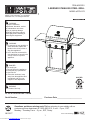 1
1
-
 2
2
-
 3
3
-
 4
4
-
 5
5
-
 6
6
-
 7
7
-
 8
8
-
 9
9
-
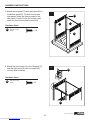 10
10
-
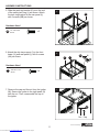 11
11
-
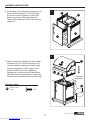 12
12
-
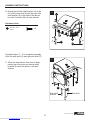 13
13
-
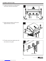 14
14
-
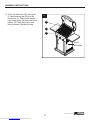 15
15
-
 16
16
-
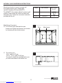 17
17
-
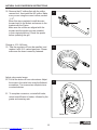 18
18
-
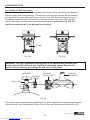 19
19
-
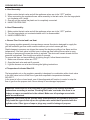 20
20
-
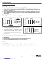 21
21
-
 22
22
-
 23
23
-
 24
24
-
 25
25
-
 26
26
-
 27
27
-
 28
28
-
 29
29
-
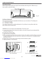 30
30
-
 31
31
-
 32
32
-
 33
33
-
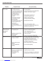 34
34
-
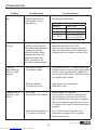 35
35
-
 36
36
-
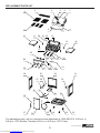 37
37
-
 38
38
-
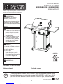 39
39
-
 40
40
-
 41
41
-
 42
42
-
 43
43
-
 44
44
-
 45
45
-
 46
46
-
 47
47
-
 48
48
-
 49
49
-
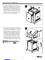 50
50
-
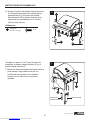 51
51
-
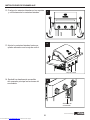 52
52
-
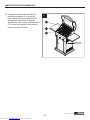 53
53
-
 54
54
-
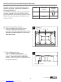 55
55
-
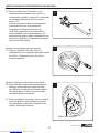 56
56
-
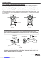 57
57
-
 58
58
-
 59
59
-
 60
60
-
 61
61
-
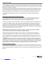 62
62
-
 63
63
-
 64
64
-
 65
65
-
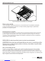 66
66
-
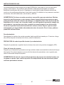 67
67
-
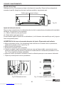 68
68
-
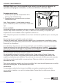 69
69
-
 70
70
-
 71
71
-
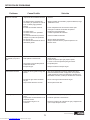 72
72
-
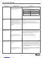 73
73
-
 74
74
-
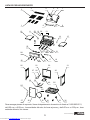 75
75
-
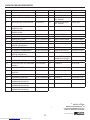 76
76


Master Forge RT2417S El manual del propietario
- Categoría
- Barbacoas
- Tipo
- El manual del propietario
en otros idiomas
- English: Master Forge RT2417S Owner's manual
Artículos relacionados
-
Master Forge 820-0033 El manual del propietario
-
-
-
-
-
-
-
-
-
Otros documentos
-
Browning BR4GRILL El manual del propietario
-
Brinkmann 810-6340-S El manual del propietario
-
-
-
Masterbuilt MB20020413 El manual del propietario
-
KitchenAid 720-0864 El manual del propietario
-
Smoke Hollow SH19032419 El manual del propietario
-
Kenmore 148.16656010 El manual del propietario
-