Nice Automation Pluto El manual del propietario
- Categoría
- Abridor de puerta
- Tipo
- El manual del propietario
La página se está cargando...

PLUTO
2
MODELLI E CARATTERISTICHE -
MODELS AND CHARACTERISTICS
- MODÈLES ET CARACTÉRISTIQUES
MODELLE UND EIGENSCHAFTEN
- MODELOS Y CARACTERÍSTICAS
DATI TECNICI -
TECHNICAL DATA
- DONNÉES TECHNIQUES -
TECHNISCHE DATEN
- DATOS TÉCNICOS
PL 4000
PL 4005
PL 4015
PL 4605
PL4615
PL5615
PL 5015
PL4024
PL5024
Irreversibile, con
sblocco, veloce.
Irreversibile, con
sblocco, veloce, con
fine corsa in apertura.
Irreversibile, con
sblocco, lento,con fine
corsa in apertura.
Reversibile, veloce, con
fine corsa
in apertura.
Reversibile, lento,
con fine corsa
in apertura.
Irreversibile, con
sblocco lento, con fine
corsa in apertura.
Motore irreversibile con
sblocco 24 Vdc, con
encoder ed
arresto meccanico
in apertura.
Irreversible, with
release, fast.
Irreversible, with
release, fast, with limit
stop on opening.
Irreversible, with
release, slow, with limit
stop on opening.
Reversible, fast,
with limit stop
on opening.
Reversible, slow,
with limit stop
on opening.
Irreversible, with
release, slow, with limit
stop on opening.
24 Vdc irreversible
motor with unlock,
en coder and
mechanical stop in
opening.
Irréversible, avec
déblocage, rapide.
Irréversible, avec dé-
blocage, rapide, avec fin
de course à l’ouverure.
Irréversible, avec dé-
blocage, lent, avec fin
de course à l’ouverture.
Réversible, rapide,
avec fin de course à
l’ouverture.
Réversible, lent,
avec fin de
course à l’ouverture
Irréversible, avec dé-
blocage, lent, avec fin
de course à l’ouverture.
Moteur irréversible avec
déblocage 24 Vdc,
encodeur et butée
mécanique en
ouverture.
Irreversibel, mit
Entblockung, schnell
Irreversibel, mit Entbloc-
kung, schnell, mit
Öffnungs Endschalter
Irreversibel, mit Entbloc-
kung, langsam, mit
Öffnungs-Endschalter
Reversibel,
schnell, mit
Öffnungs-Endschalter
Reversibel,
angsam, mit
Öffnungs-Endschalter
Irreversibel, mit Entbloc-
kung, langsam, mit
Öffnungs-Endschalter.
Reversibler 24 Vdc
Motor mit Entriegelung,
Encoder und
mechanischem
Endanschlag in Öffnung.
Irreversible, con
desbloqueo, veloz.
Irreversible, con
desbloqueo, veloz, con final
de carrera en apertura
.
Irreversible, con
desbloqueo, lento, con final
de carrera en apertura.
Reversible, veloz, con
final de carrera en
apertura.
Reversible, lento, con
final de carrera en
apertura.
Irreversible, con
desbloqueo, lento, con final
de carrera en apertura.
Motor irreversible con
desbloqueo 24 Vdc,
con codificador y
parada mecánica
durante la apertura.
I GB F D E
Unità di misura -
Unit of measure
Unité de mesure -
Maßeinheit
Unidad de medida
Alimentazione -
Power supply
Alimentation -
Speisung
Alimentación
Vac 50 Hz
Vdc
A
W
µF
m/s.
mm
N
°C (Min./Max.)
°C
%
kg
Potenza assorbita -
Absorbed power
Puissance absorbée -
Aufgenommene
Potencia Absorbida
Condensatore incorporato -
Condenser built-in
Condensateur incorporé -
Kondensator
eingebaut -
Condensator incorporado
Corrente -
Current -
Courant
Strom -
Intensidad
Velocità -
Speed
- Vitesse
Geschwindigkeit -
Velocidad
Spinta max. -
Maximum thrust
- Pousèe
maximum -
Max. Schub
- Empuje max.
Temperatura di esecizio -
Working
temperature -
Température de service
Betriebstemperatur
Temperatura de servicio
Ter moprotezione -
Thermal protection
Protection thermique -
Wärmeschutz
Ter moproteccion
Ciclo di lavoro -
Working cycle
Cycle de travail -
Arbeitszyklus
Ciclo de trabajo
Peso motore -
Motor weight
Poids moteur -
Motorgewicht
Peso del motor
PL 4000
PL 4005
PL 4015
PL 4605
PL 4615
PL 4024
PL 5024
PL 5015
PL 5615*
Corsa -
Travel
- Course -
Hub -
Carrera
230 230
1.3
24
5 1.3
300 120 300
10 -
-
10
0.016 0.013 0.021 0.017 0.014 0.013 0.017
370 320 470
1700 1800
1700 1800 1600 1800
150 - 150
30 100 30
8 8.5 8 8.5 9
-20° ÷ +70°

PLUTO
3
CHECKING
AND PRELIMINARY
PROCEDURES
CONTRÔLES
PRÉLIMINAIRES
PRÜFUNGEN
UND VORBEREITENDE
ARBEITEN
LIMITI DI IMPIEGO -
LIMITS OF USE
- LIMITES D' UTILISATION -
EINSATZGRENZEN
- LÍMITES DE EMPLEO
GB
I
F
D
E
QUADRO D' INSIEME -
OVERALL PICTURE
- CADRE GÉNÉRAL -
ÜBERSICHTZEICHNUNG
- ESQUEMA DE CONJUNTO
1) Column for photocell.
2) Pair of opening stops*.
3) 230 V line.
4) Control panel (or
electronic control unit).
5) Aerial.
6) Flashing light.
7) Photocell.
8) PLUTO actuator.
9) Vertical electric lock**
(PLA10).
10) Key selector or digital
keyboard.
* to be installed only on
models without limit switch.
** to be installed when
using the reversible models
PL 4605 - PL 4615, or when
each wing of the gates is
more than 3 mt long.
*** Mod. 4024 - 5024 cable
5x1,5
1) Säule für Photozelle
2) Paar Öffnungssperren
3) Linie 230 V
4) Schalttafel (oder elektro-
nisches Steuergerät)
5) Antenne
6) Blinklicht
7) Photozelle
8) PLUTO-Trieb
9)
Vertikales Elektroschloß**
(PLA10).
10) Schlüsselschalter oder
Digital-Tastatur
* nur für Modelle ohne
Endschalter
** für die reversiblen Mo-
delle PL 4605 und PL 4615,
oder wenn die einzelnen
Torflügel länger als 3 m sind.
*** Mod. 4024 - 5024 Kabel
5x1,5
1) Columna para foto-
célula.
2) Par de topes en apertura*
3) Línea 230 V~
4) Cuadro de mando (o
centralita electrónica)
5) Antena
6) Intermitente
7) Fotocélula
8) Actuator PLUTO
9) Electrocerradura
vertical **(PLA10).
10) Selector de llave o
teclado digital
* Sólo se tiene que
instalar en los modelos sin
finales de carrera.
** Se tiene que instalar si se
utilizan los modelos reversibles
PL 4605 y PL 4615 siempre que
cada hoja de las cancelas
supere los 3 m de longitud.
*** Mod. 4024 - 5024 Cable
5x1,5
2 x 1,5-
part 6
VERIFICHE E
PRELIMINARI
I
GB
F
D
E
CONTROLES Y
PRELIMINARES
A) Leer atentamente las
instrucciones.
B) Antes de efectuar la
instalación, comprobar que
la estructura de la cancela
sea robusta y adecuada.
C) Comprobar que la
cancela, durante todo su
movimiento, no presente
puntos de roce.
A) Lire attentivement les
instructions.
B) Avant de passer à
l’installation, s’assurer que
la structure de la grille soit
solide et appropriée.
C) S’assurer que la grille
n’ait pas de points de
frottement durant tout le
mouvement.
A) Read the instructions
carefully.
B) Before starting
installation, ensure that the
structure of the gate is sturdy
and appropriate.
C) Ensure that there is no
point of friction during the
entire movement of the gate.
A) Leggere attentamente
le istruzioni.
B) Prima di passare all'in-
stallazione, accertarsi che
la struttura del cancello sia
solida ed appropriata.
C) Accertarsi che il cancel-
lo, durante tutto il suo movi-
mento, non subisca punti di
attrito.
A) Lesen Sie die
Anleitungen aufmerksam
durch.
B) Vor der Installation
sicherstellen, daß die
Struktur Ihres Tors solide
und für die Montage
geeignet ist.
C) Sicherstellen, daß das
Tor während der gesamten
Bewegung auf keine
Reibpunkte trifft.
1) Petite colonne pour cel
lule photo-électrique
2) Couple de butées en
ouverture*
3) Ligne à 230V
4) Pupitre de commande
5) Antenne
6) Clignoteur
7) Cellule photo-électrique
8) Actionneur Pluto
9) Serrure électrique
verticale**(PLA10).
10) Sélecteur à clé ou
clavier numérique
*à installer uniquement sur
les modèles sans fin de course
** à installer si l’on utilise
les modèles réversibles PL
4605 et PL 4615, ou lorsque
la grille a plus de trois
mètres de longueur pour
chacune des portes.
*** Mod. 4024 - 5024 cable
5x1,5
*da installare solo nei mo-
delli privi di finecorsa
** da installare se si utilizzano
i modelli reversibili PL 4605 - e
PL 4615, o qualora il cancello
superi i mt. 3 di lunghezza per
ogni singola anta.
*** Mod. 4024 - 5024 cavo
5x1,5
1) Colonnina per
fotocellula.
2) Coppia di arresti in
apertura*.
3) Linea 230 V~
4) Quadro di comando (o
centralina elettronica)
5) Antenna.
6) Lampeggiatore.
7) Fotocellula.
8) Attuatore PLUTO.
9) Elettroserratura
verticale**(PLA10)
10) Selettore a chiave o
tastiera digitale
4
5
6
7
9
7
10
RG58 -
part. 5
7 7
3
3 x 1,5
4 x 1
4 x 1,5
1
2
8
2 x 1
4 x 1
2 x 1
3 x 1
2 x 1
1
2
8
4 x 1,5
***
2 2,5 3 3,5 4 4,5 5
5000
4000
800
700
600
500
400
300
200
Kg
m
Peso massimo anta
Maximum wing weight
Poids
Max Flügelgewicht
Peso màximo de la hoja
Lunghezza massima anta - Maximum wing lenht - Longuer maximum
Max Flügellänge - longitud màxima de la hoja

PLUTO
4
DIMENSIONI D' INGOMBRO -
DIMENSIONS
- DIMENSIONS D’ENCOMBREMENT -
RAUMBEDARF
- DIMENSIONES
Tabella apertura cancello -
Gate opening table
- Tableau ouverture portail -
Toröffnungstabelle
- Tabla apertura puerta
I
E
Misura la distanza “C” e traccia una
linea orizzontale.
Measure the “C” distance and trace
a horizontal line.
Mesurer la distance “C” et tracer
une ligne horizontale.
Messen Sie die Entfernung “C” und
zeichnen eine horinzontale Linie.
Medir la distancia “C” y trazar una
linea horizontal.
GB
F
D
D 720 (*870)
795 (*945)
370
45
110
109
(*470)
F D
E
GB
I
Scegli quanto aprire il cancello
(
)
Choose how far to open the gate
(
)
Choise l'ampleur d'ouverture du
portail (
)
Wählen Sie, wie weit Sie das Tor
öffnen möchten (
)
Elegir cuánto abrir la puerta
(
)
I
GB
F
D
E
Trova A
min. 110 max. 160
Find A
min. 110 max. 160
Trouver A
min. 110 max. 160
A finden A
min. 110 max. 160
Encontrar A
min. 110 max. 160
Esempio di utilizzo grafico, con spessore cancello di 50 mm.
Example of using a graph, with 50 mm thick gate.
Exemple d'utilisation graphique, avec portail de 50 mm d'epaisseur.
Beispiel für graphische Anwendungen, mit 50 mm Torstärke.
Ejemplo de uso gráfico, con espesor cancela de 50 mm.
( )
* PL 5015
PL 5615
PL 5024
E
Per valori di A e B piccoli si hanno velocità ALTE, per valori A e B grandi si hanno velocità BASSE.
For A and B small values we have HIGH speeds; for A and B large values we have LOW speeds.
Quand les valeurs A et B sont petites, les vitesses sont ÈLEVÈES, quand les valeurs A et B sont grandes, les vitesses sont BASSES.
Bei kleine A- und B Werten erzielt man SCHNELLE Geschwindigkeiten, bei grosse A- und B Werten erzielt man LANGSAME Geschwindigkeiten.
Con valores de A y B bajos se obtienen velocidades ALTAS; para valores de A y B altos se obtienen velocidades BAJAS.
D
F
GB
I

PLUTO
5
α
CB
E
A
C
B
D
A
APERTURA CANCELLO VERSO L'ESTERNO -
GATE OPENING TO THE EXTERNAL
- OUVERTURE DU PORTAIL A L'EXTERIEUR
TOR ÖFFNUNG NACH AUßEN
- APERTURA PUERTAS HACIA AFUERA
Per tutti i modelli
For all serie
Pour tous les models
Für alle modelle
Para todos
los modellos
I
GB
F
D
E
Esempio apertura a 90° per i modelli 4000 con staffa posteriore standard e con B≥90.
An example of opening at 90
°
for the models 4000 with standard rear bracket and with B
≥
90.
Exemple ouverture à 90° pour les modèles 4000 avec patte de fixation arrière standard et avec B≥90.
Beispiel der 90
°
Öffnung für die Modelle 4000 mit hinterem Standardbügel und mit B
≥
90.
Ejemplo de apertura a 90° para los modelos 4000 con estribo trasero estándar y con B≥90.
I
GB
F
D
E
Per i modelli 5000 utilizzare la staffa opzionale PLA 6, mantenendo B≥90.
For the models 5000 use the optional bracket PLA 6, maintaining B
≥
90.
Pour les modèles 5000 utiliser la patte de fixation en option PLA 6, en maintenant B≥90.
Für die Modelle 5000 den Sonderbügel PLA 6 benützen und B
≥
90 beibehalten.
Para los modelos 5000, utilice el estribo opcional PLA 6, manteniendo B≥90.
I
GB
F
D
E
A = 100
B = 90
E = 120

PLUTO
6
3
2
1
4
5
1 - Screw 10x40 UNI 5737
2 - Washer diam. 10 UNI
6592
3 - Self-locking nut M10 UNI
7473
4 - Washer 8x24 UNI 6593
5 - Screw 8x10 UNI 5739
IMPORTANT:
Fully tighten the self-
locking nuts, then
unscrew them both by
about 1/10 of a turn to
allow a certain amount of
clearance between the
parts.
1 - Tornillo 10x40 UNI 5737
2 - Arandela ø 10 UNI 6592
3 - Tuerca autoblocante M
10 UNI 7473
4 - Arandela 8x24 UNI 6593
5 - Tornillo 8x10 UNI 5739
IMPORTANTE:
Enroscar completamente
las tuercas autoblocantes
y, luego, desenroscarlas
1/10 de vuelta para
permitir un cierto juego
entre las piezas.
1- Vite 10x40 UNI 5737
2 - Rondella ø 10 UNI 6592
3 - Dado autobloccante
M 10 UNI 7473
4 - Rondella 8x24 UNI 6593
5 - Vite 8x10 UNI 5739
IMPORTANTE:
Avvitare completamente
il dado autobloccante e
quindi svitarlo di circa
1/10 di giro per permette-
re un certo gioco tra le
parti.
1 - Vis 10X 40 UNI 5737
2 - Rondelle ø10 UNI 6592
3 - Ecrou de sûreté M 10
UNI 7473
4 - Rondelle 8x24 UNI 6593
5 - Vis 8x10 UNI 5739
IMPORTANT:
Visser complètement les
écrous de sûreté et les
dévisser ensuite
d’environ 1/10 de tour
pour permettre d’avoir un
certain jeu entre les
différentes parties.
1 - Schraube 10x40 UNI
5737
2 - Unterlegscheibe Ø 10
UNI 6592
3 - Selbstsperrende Mutter
M10 UNI 7473
4 - Unterlegscheibe 8x24
UNI 6593
5 - Schraube 8x10 UNI 5739
WICHTIG:
Die beiden selbstsper-
renden Muttern ganz
festziehen und anschlie-
ßend um ungefähr 1/10
Umdre-hung lockern,
damit zwischen den
Teilen ein gewisses Spiel
ermöglicht wird.
D
E
F
I
GB
FISSAGGIO ANTERIORE
FRONT FASTENING
FIXAGE ANTÉRIEUR
VORDERE BEFESTIGUNG
FIJACIÓN ANTERIOR
FISSAGGIO POSTERIORE
REAR FASTENING
FIXAGE POSTÉRIEUR
HINTERE BEFESTIGUNG
FIJACIÓN POSTERIOR
F
F
I
GB
I
GB
D
E
D
E
INSTALLATION
1) Staffa posteriore
2) Staffa anteriore
3) Piastra di attacco
4) Linea orizzontale
1) Rear bracket
2) Front bracket
3) Connecting plate
4) Horizontal line
1) Etrier postérieur
2) Etrier antérieur
3) Plaque de fixation
4) Ligne horizontale
1) Hinterer Bügel
2) Vorderer Bügel
3) Anschlagplatte
4) Horizontale
5) Brida posterior
2) Brida anterior
3) Placa de fijación
4) Linea horizontal
I
F E
D
INSTALLAZIONE
INSTALLATION
INSTALLATION
INSTALACION
GB
I
GB
E
D
F

PLUTO
7
MANOVRA
MANUALE
MOD. PL 4000 / 4005 / 4015 / 4024 / 5015 / 5024
MANUAL
MANOEUVRE
MANŒUVRE
MANUELLE
MANUELLE
BEDIENUNG
MANIOBRA
MANUAL
I
GB
F D
E
1
I F D
E
A) Slide the lock cover (1)
back as indicated.
B) Insert the key and turn it
at a right angle in a
clockwise direction.
C) Lift the lever, pulling
first on the key itself, then on
the lever until it reaches
vertical position.
D) To restore automatic
function, lower the lever into
horizontal position, turn the
key at a right angle in an
anti-clockwise direction,
remove the key and slide
the lock cover closed until it
stops.
ATTENTION: La ma-
noeuvre manuelle permet
une course "libre" de
l'actionneur seulement
s'il est correctement
monté et avec les
accessoires originaux.
WARNING: The manual
operation allows a "free"
travel of the actuator only
if correctly mounted and
with the original
accessories.
ATTENZIONE : La mano-
vra manuale consente
una corsa "libera"
dell'attuatore solo se
montato correttamente e
con gli accessori origina-
li.
A) Abrir la tapa (1) de la
cerradura de la manera
ilustrada.
B) Poner la llave y girarla
90° en el sentido de las
manecillas del reloj.
C) Levantar tirando
inicialmente de la misma
llave y, luego, de la
palanca, hasta quedar en
vertical.
D) Para restablecer el
funcionamiento
automático, es suficiente
bajar la palanca en posición
horizontal, cerrar con la
llave girándola unos 90° en
el sentido de las manecillas
del reloj, quitarla y
desplazar la tapa de la
cerradura hasta el tope.
A) Die Schloßabde-
ckung (1) in Pfeilrichtung
verschieben.
B) Den Schlüssel
einstecken und um 90°
nach rechts drehen.
C) Zunächst mit dem
Schlüssel und dann mit dem
Hebel anheben, bbis die
vertikale Stellung erreicht
ist.
D) Für die Wiederher-
stellung der automatischen
Funktion den Hebel wieder
horizontal stellen, den
Schlüssel umdrehen und
abziehen und zuletzt die
Schloßabdeckung bis zum
Einrasten verschieben.
A) Faire glisser en arrière
le couvre-serrure (1) en
suivant les indications du
dessin.
B) Insérer la clé dans la
serrure e la faire tourner à
90° dans le sens des
aiguilles d’une montre.
C) Soulever en tirant tout
d’abord sur la clé puis sur le
levier afin d’arriver à la
position verticale.
D) Pour remettre en
fonctionnement auto-
matique, baisser le levier en
position horizontale, fermer
à clé et tourner celle-ci à 90°
dans le sens contraire des
aiguilles d’une montre et
faire glisser le couvre-
serrure jusqu’au bout.
A) Far scorrere all'indietro il
copriserratura (1) come in-
dicato.
B) Inserire la chiave e
ruotarla in senso orario di
90°.
C) Sollevare tirando inizial-
mente sulla chiave stessa,
poi sulla leva fino a raggiun-
gere la posizione verticale.
D) Per ripristinare in funzio-
namento automatico, sarà
sufficiente abbassare la
leva in posizione orizzonta-
le, chiudere a chiave,
ruotarla in senso antiorario
di 90°, toglierla e fare scor-
rere il copriserratura fino al
suo arresto.
GB
ACHTUNG: Das manuelle
Manöver gestattet nur
dann einen "freien" Hub
des Triebs, wenn er
korrekt und mit den
Originalzubehörteilen
montiert worden ist.
ATENCION: La maniobra
manual permite una
carrera "libre" del
accionador sólo si se
instala correctamente y
con los accessorios
originales.
I
A) SBLOCCARE L'ELETTROSERRATURA.
B) AGIRE MANUALMENTE SUL CANCELLO.
A) RELEASE THE ELECTRIC LOCK.
B) OPEN THE GATE BY HAND.
A) DÉBLOQUER LA SERRURE ÈLECTRIQUE.
B) AGIR SUR LE PORTAIL MANUELLEMENT.
GB
A) DEN ELEKTROVERSCHLUSS ABSTELLEN.
B) DAS TOR MANUELL BEDIENEN.
A) DESBLOQUEAR LA ELECTROCERRADURA.
B) ACCIONAR MANUALMENTE LA CANCELA.
F
D
E
MOD. 4605 / 4615 / 5615

8
PLUTO
INFORMAZIONI PER L’UTENTE
Ad installazione avvenuta, l’utente deve essere informato sulle prestazioni del PLUTO, e di tutti i rischi che possono derivare da
un uso improprio o scorretto.L’utente deve evitare di porsi in situazioni di pericolo, cioè stazionare nel raggio d’azione della porta
quando essa è in movimento, non opporsi al movimento della porta stessa, vietare ai bambini di giocare in prossimità della porta
e tenere fuori dalla loro portata i telecomandi.
Tutti gli interventi di manutenzione, riparazione o verifiche periodiche devono essere eseguiti da personale professionalmente
qualificato e documentati su apposito registro manutenzione custodito dall’utilizzatore.
• In caso di anomalia, l’utente deve astenersi da qualsiasi tentativo di intervento e chiamare l’installatore per la riparazione.
• L’utente può solo eseguire la mano
vra manuale
.
INFORMATION FOR THE USER
Once the gearmotor has been installed, the user must be informed about how it works and all the risks that can arise from an
improper use.The user must avoid placing himself in dangerous positions such as standing within the door’s range of action when
it is moving, opposing its movement.
Do not let children play near the door and keep the remote control out of their reach.
All servicing, repairs or checks must be carried out by professionally qualified personnel and noted on a maintenance register
kept by the user.
• In the case of malfunctioning the user must call the installer and not attempt to repair it himself.
• The user can only carry out the manual manoeuvre.
INFORMATIONS POUR L’UTILISATEUR
Une fois l’installation terminée, l’utilisateur doit Ítre informé sur les performances du PLUTO et sur tous les risques qui peuvent
dériver d’une utilisation impropre ou incorrecte. L’utilisateur doit éviter de se mettre en situation de danger, c’est-à-dire de
stationner dans le rayon d’action de la porte quand celle-ci est en mouvement; il ne doit pas non plus s’opposer au mouvement
de la porte.Il faut interdire aux enfants de jouer à proximité de la porte et il faut faire en sorte qu’ils ne puissent pas accéder aux
télécommandes.
Toutes les interventions d’entretien, réparation ou de contrÙle périodique doivent Ítre effectuées par du personnel
professionnellement qualifié et elles doivent Ítre documentées dans un registre d’entretien conservé par l’utilisateur.
• En cas d’anomalie, l’utilisateur doit s’abstenir de toute tentative d’intervention et faire appel à l’installateur pour la réparation.
•L’utilisateur peut seulement effectuer la manoeuvre man
uelle.
INFORMATIONEN FÜR DEN BENUTZER
Nach erfolgter Installation muss der Benutzer über die Leistungen des PLUTO and über alle Risikos informiert werden, die durch
einen unsachgemäßen oder unkorrekten Gebrauch verursacht werden können. Der Benutzer muss vermeiden, sich in
Gefahrensituationen zu begeben, d.h. er darf nicht im Aktionskreis der sich bewegenden Tür verweilen, sich nicht der Bewegung
der Tür widersetzen, er muss die Fernsteuerungen außer der Reichweite von Kindern halten und er muss diesen verbieten, in
der Nähe der Tür zu spielen.
Alle Wartungsarbeiten, Reparaturen oder regelmäßigen Überprüfungen dürfen nur von qualifiziertem Fachpersonal ausgeführt
werden und müssen im Wartungsbuch, das vom Benutzer aufbewahrt wird, eingetragen sein.
• Im Fall von Störungen muss sich der Benutzer Eingriffen enthalten und den Installateur mit der Reparatur beauftragen.
• Der Benutzer darf nur die manuelle Betätigung ausführen.
INFORMACIONES PARA EL USUARIO
Cuando haya finalizado la instalación, informe al usuario sobre los rendimientos de PLUTO y sobre todos los riesgos que puede
correr a causa de un uso impropio o incorrecto del mismo. El usuario tiene que evitar situaciones de peligro, es decir pararse en
el radio de acción de la puerta cuando la misma está en movimiento, oponerse al movimiento de la misma, también tiene que
prohibir a los niños jugar en proximidad de la puerta y mantener fuera del alcance de los mismos los controles remotos.
Todas las operaciones de mantenimiento, reparación, o controles periódicos tienen que ser efectuados por personal cualificado,
registradas en el registro de mantenimiento y conservadas por el usuario.
• En caso de anomalía, el usuario se tiene que abstener de efectuar cualquier reparación y llamar al instalador.
• El usuario puede efectuar sólo la maniobra manual.
I
GB
F
D
E
✃

PLUTO
9
CONNETTORE
CONNECTOR
CONNECTEUR
BUCHSE
CONECTOR
D
E
F
I
GB
1) Guarnizioni
2) Portacontatti
3) Vite serrafilo
4) Protezione
5) Pressacavo
6) Rondella
7) Serracavo
8) Vite fissaggio
N.B. Il connettore garanti-
sce una protezione IP65
DIN 40050 solo se monta-
to correttamente come
rappresentato in figura.
1) Garniture
2) Boîte des fils
électriques
3) Vis serre-fils
4) Protection
5) Presse-câble
6) Rondelle
7) Serre-câble
8) Vis de fixage
N.B. Le connecteur
assure une protection
IP65 DIN 40050
uniquement s’il est monté
correctement en suivant
les indications du dessin.
1) Junta
2) Portacontactos
3) Tornillo de apriete del
hilo.
4) Protección
5) Prensacable
6) Arandela
7) Tuerca de apriete del
cable
8) Tornillo de fijación
N.B.: El conector
garantiza una protección
IP65 DIN40050 sólo si está
montado correctamente
tal como se ilustra en la
figura.
D
E
F
I
GB
1) Dichtung
2) Kontakthalter
3) Klemmschraube
4) Sicherung
5) Kabelklemme
6) Unterlegscheibe
7) Kabelhalterung
8) Befestigungsschraube
N.B.: der Verbinder
sichert nur dann einen
Schutzgrad IP65 DIN
40050, wenn er korrekt
montiert ist, wie in der
Abbildung gezeigt.
1) Gasket
2) Contact holder
3) Wire clamping screw
4) Protection
5) Grommet
6) Washer
7) Cable clamp
8) Retaining screw
N.B. The connector
guarantees protection
according to IP65 DIN
40050 only if assembled
correctly as shown in the
figure.
1 = “Open” phase
2 = “Close” phase
3 = Common
= Earth
N.B. THE CONDENSER IS
ALREADY CONNECTED
INSIDE THE ACTUATOR.
1 = Phase d’ouverture
2 = Phase de fermeture
3 = Commun
= Terre
N.B. LE CONDENSA-
TEUR EST DÉJÀ
RACCORDÉ À L’INTÉ-
RIEUR DE L’ACTION-
NEUR.
1 = Fase "abre"
2 = Fase "cierre"
3 = Común
= Tierra
NB: EL CONDENSATOR
YA ESTÁ CONECTADO
POR EL INTERIOR CON
EL ACCIONADOR.
1 = Fase "apre"
2 = Fase "chiude"
3 = Comune
= Terra
N.B. IL CONDENSATORE
È GIÀ COLLEGATO
INTERNAMENTE
ALL'ATTUATORE.
1 =Phase “Öffnen”
2 =Phase “Schließen”
3 =Mittelleiter
=Erdung
N.B.: DER KONDEN-
SATOR IST BEREITS
INTERN MIT DEM TRIEB
VERBUNDEN.
D
E
F
I
GB
CONEXIONES
DEL MOTOR
MOTOR-
ANSCHLÜSSE
MOTOR
CONNECTIONS
COLLEGAMENTI
DEL MOTORE
BRANCHEMENTS
DU MOTEUR
8
3
2
4
5
6
7
1
PL 4000
PL 4005
PL 4015
PL 4605
PL 4615
PL 5015
PL 5615

PLUTO
10
1) Motore +
2) Motore -
3) Encoder +
4) Encoder -
1) Motor +
2) Motor -
3) Encoder +
4) Encoder -
1) Moteur +
2) Moteur -
3) Encoder +
4) Encoder -
1) Motor +
2) Motor -
3) Encoder +
4) Encoder -
1) Moteur +
2) Moteur -
3) Encoder +
4) Encoder -
4
D E
FI
GB
PL 4024
PL 5024
D
E
F
I
GB
CONEXIONES
DEL MOTOR
MOTOR-
ANSCHLÜSSE
MOTOR
CONNECTIONS
COLLEGAMENTI
DEL MOTORE
BRANCHEMENTS
DU MOTEUR
D E
F
I
GB
CONEXION AL
ACCIONADOR
KUPPLING ZUM
TRIEB
COUPLING TO
THE ACTUATOR
INNESTO
ALL'ATTUATORE
RACCORD Å
L'ACTIONNEUR
ATTENZIONE:
Si ricorda di collegare sem-
pre il cavo di terra come
previsto dalle normative vi-
genti.
(EN 60204 - CEI 64-1 - EN 60335).
WARNING:
Remember that the earth
wire must always be
connected as established
by current laws.
(EN 60204 - CEI 64-1 - EN 60335).
ATTENTION:
Nous rappelons que le
câble de mise à la terre doit
toujours être connecté en
respectant les normes en
vigueur.
(EN 60204 - CEI 64-1 - EN 60335).
ACHTUNG:
Immer das Erdkabel
anschließen, wie von den
gültigen Vorschriften
vorgesehen.
(EN 60204 - CEI 64-1 - EN 60335).
ATENCION:
Recuerde conectar siempre
el cable de tierra como
dispuesto por las normas en
vigor.
(EN 60204 - CEI 64-1 - EN 60335).
D E
FI
GB
'

PLUTO
11
Il fine corsa in apertura è un microinterruttore già collegato sulla fase "apre" dell'attuatore, questo permette di regolare la posizione di arresto in
apertura evitando così di dover usare i franchi di arresto e di fare sbattere il cancello sugli stessi.
The opening limit switch is a microswitch already connected to the “open” phase of the actuator; this allows regulation of
the stop position on opening, thus avoiding having to use the mechanical stops and letting the gate bang against them.
La fin de course en ouverture est un micro-interrupteur déjà relié à la phase “ouverture”
de l’actionneur; ceci permet de régler la position d’arrêt en ouverture, en évitant ainsi
d’utiliser les butées et de faire heurter la barrière sur ces-dernières.
Der Öffnungs-Endschalter ist ein bereits mit der Phase
“Öffnen” des Triebs verbundener Mikroschalter und ermöglicht
die Einstellung der maximalen Öffnungsposition, wodurch die
Verwendung von Stoppern und das Schlagen des Tors gegen
dieselben vermieden wird.
2
1
4
3
El final de carrera en apertura es un
microinterruptor ya conectado con la fase "abre" del
actuador. Permite regular la posición de detención en
apertura y evita tener que usar los elementos de tope
y que la cancela los golpee.
1) Vite di fissaggio.
2) Supporto inferiore microinterruttore.
3) Microinterruttore.
4) Supporto superiore microinterruttore.
A) Allentare la vite (1) con chiave a brugola
da mm 6.
B) Regolare quindi la posizione del blocco di
fine corsa fino a portarlo al punto desiderato
agendo sulla vite stessa.
C) Bloccare energicamente la vite (1).
I
1) Retaining screw
2) Bottom microswitch support
3) Microswitch
4) Top microswitch support
A) Slacken the screw (1) with a 6 mm Allen
wrench.
B) Then regulate the limit switch block, turning
the screw to bring the block into the desired
position.
C) Firmly tighten the screw (1).
1) Vis de fixage
2) Support inférieur du micro-interrupteur
3) Micro-interrupteur
4) Support supérieur du micro-interrupteur
A) Desserer la vis (1) avec une clé à vis pour six
pans creux 6mm.
B) Régler ensuite la position du bloc de fin de
course afin de le porter à l’endroit désiré en
tournant la vis.
C) Bloquer energiquement la vis (1).
D
I
F
D
E
REGOLAZIONE DEL FINE CORSA IN APERTURA
(ESCLUSO MOD. PL 4000)
REGULATING THE OPENING LIMIT SWITCH
(EXCEPT MOD. PL 4000)
RÉGLAGE DE FIN DE COURSE EN OUVERTURE
(SONT EXCLUS LES MODULES PL 4000)
EINSTELLUNG DES ÖFFNUNGS-ENDSCHALTERS
(AUSSCHLIESSLICH MOD. PL 4000)
REGULACIÓN DEL FINAL DE CARRERA EN APERTURA
(SALVO MODELOS PL 4000)
GB
GB
GB
F
I
F
D
E
1) Befestigungsschraube
2) Halterung unterer Mikroschalter
3) Mikroschalter
4) Halterung oberer Mikroschalter
A) Die Schraube (1) mit einem Inbusschlüssel
zu 6 mm lockern.
B) Die Halteposition des Endschalters durch
Einwirken auf die Schraube auf den
gewünschten Punkt einstellen.
C) Die zuvor gelockerte Schraube (1).
1) Tornillo de fijación
2) Soporte inferior del microinterruptor
3) Microinterruptor
4) Soporte superior del microinterruptor
A) Aflojar el tornillo (1) con una llave Allen
de 6 mm.
B) Regular la posición el bloque de final de
carrera hasta ponerlo en el punto deseado
actuando en el mismo tornillo.
C) Bloquear hasta el tope el tornillo (1).
E

PLUTO
12
5
3
2
1
5
7
I
MONTAGGIO
ELETTROSERRATURA
1) Elettroserratura.
2) Piastra di fissaggio elettroserratura.*
3) Aggancio chiavistello.*
4) Battuta per aggancio.
5) Chiavistello.
6) Barilotto passante.
7) Cancello.
* Specificare se orizzontale o verticale.
FITTING THE ELECTRIC LOCK
1) Electric lock.
2) Plate for fixing the electric lock.*
3) Latch connection.*
4) Connection rabbet.
5) Latch.
6) Through cylinder.
7) Gate.
* Specify whether horizontal or vertical.
MONTAGE DE LA SERRURE
ÉLECTRIQUE
1) Serrure électrique
2) Plaque de fixage de la serrure électrique*
3) Attache du verrou
4) Feuillure pour l’attache
5) Verrou
6) Baricaut passant
7) Grille
* Préciser si elle est horizontale ou verticale.
MONTAGE DES
ELEKTROSCHLOSSES
1) Elektroschloß
2) Anschlagplatte Elektroschloß *
3) Riegelanschlag *
4) Anschlag
5) Riegel
6) durchgehender Zylinder
7) Tor
* Angeben, ob horizontal oder vertikal
MONTAJE DE LA
ELECTROCERRADURA
1) Electrocerradura
2) Placa de fijación de la electrocerradura*
3) Enganche del pestillo*
4) Tope para enganche
5) Pestillo
6) Cilindro pasante
7) Cancela
* Indicar si horizontal o vertical
F
D
E
GB
7
2
4
3
1
6
• Fissaggio verticale (per due ante)
• Vertical fastening (for two wings)
• Fixage vertical (pour deux portes)
• Vertikale Befestigung (für zwei Flügel)
• Fijación vertical (para dos hojas)
F
E
D
GB
I
6
• Fissaggio orizzontale (per una sola anta)
• Horizontal fastening (for only one wing)
• Fixage horizontal (pour une seule porte)
• Horizontale Befestigung (für nur einen Flügel)
• Fijación horizontal (para una sola hoja)
F
E
D
I
GB
4

PLUTO
13
ACCESSORIES
ON REQUEST
- Staffa posteriore lunga mm 250.
- Rear bracket 250 mm long.
- Etrier postérieur longueur 250mm.
- Hinterer Bügel, Länge 250 mm
- Brida posterior de 250 mm de longitud.
- Staffa anteriore da avvitare.
- Screw-on front bracket.
- Etrier antérieur à visser.
- Vorderer Bügel zum Einschrauben
- Brida anterior para enroscar.
- Elettroserratura 12 Vca verticale.
- Vertical 12 Vac electric lock.
- Serrure électrique 12 V C A verticale
- vertikales Elektroschloß 12 V C A
- Electrocerradura 12 V C A vertical.
- Elettroserratura 12 Vca orizzontale.
- Horizontal 12 Vac electric lock.
- Serrure électrique 12 V C A horizontale
- Horizontales Elektroschloß 12 V C A
- Electrocerradura 12 V C A horizontal.
I
F
D
E
I
F
D
E
I
F
D
E
I
GB
GB
GB
F E
D
ACCESSORI A
RICHIESTA
ACCESSOIRES
SUR DEMANDE
AUF ANFRAGE
ERHÄLTLICHES
ZUBEHÖR
ACCESORIOS A
PEDIDO
GB
I
E
GB
F
D
PLA 6
PLA 7
PLA 10
PLA 11

PLUTO
14
CATALOGO RICAMBI
SPARE PARTS CATALOGUE
GB
I
CATALOGUE DES RECHANGES
ERSATZTEILKATALOG
CATÁLOGO DE RECAMBIOS
F
E
D

15
DescripciònBeschreibungDescriptionDescriptionDescrizione
PLUTO
1
2
3
4
5
6
7
8
9
10
11
12
13
14
15
16
17
18
19
20
21
22
23
24
25
26
27
28
29
30
31
32
33
34
35
36
37
38
39
40
41
42
43
44
45
46
47
48
49
50
51
52
*
Pos.
Cod.
Code
BPMS 4540
CM-B 1630
PMCU-1 4630
PEDS50 4650
GOR1 5501
PMPS 4610
PMCBR1 4630
MO-B 2640
PMCSE15 4630
PMDAP 4610
PMDSS 4610
PMD55 4630
PMDIC 4630
MMCT 2620
CGU5 5310
V6.3X19 5101
V2.9X9.5-A 5101
PMCBR 4630
V4.2X9.5 5101
V2.9X19 5101
PLA 10
PMDIC1 4610
PMCS4 4630
PMCU3 4630
PMCSE25 4630
PMPU 4610
V6X10 5101
V6.3X25 5101
PMDSMA 4610
R8 5120
V8X10 5102
10U450 0727
C4VFMPM 2065
C4VMPM 2063
BMFOR 4567
R10 5120
D10 5110
V10X40 5101
PMDSMP 4610
PMDPA 4610
CMPL 8003
PMDSMS 4610
PMCSMI 4610
RØ8 5120
V8X20 5102
Guscio superiore
*
Guscio inferiore
*
Sblocco motore
Chiave cil. Meroni
Cuscinetto 17x35x10
Albero motore
*
Statore
O-Ring
Perno di sblocco
Bronzina 12x16x12
Ingranaggio M=1.25 - Z= 22
*
Molla di sblocco
Anello seeger Ø 15
Albero condotto
Spina di sblocco 6x24
Chiavetta acciaio 5x5x10
Ingranaggio conico Z= 16
Occhiello isolato
Etichetta adesiva
Guaina PVC
Vite autofil. 6.3x19
Vite autofil. 2.9x9.5
Bronzina 12x16x6
Vite autofil. 4.2x9.5
Vite autofil. 2.9x19
Motore 24 Vdc
Ingranaggio conico con codolo
Spina cilindrica acciaio 4x25
Cuscinetto 25x47x12
Anello seeger Ø25 UNI 7435
Vite rullata
*
Chiocciola
*
Forcella per snodo anteriore
Vite 6x10 UNI 5739
Vite 6.3x25 UNI 5931
Staffa anteriore
Rondella Ø 8x24 UNI 6593
Vite 8x10 UNI 5739
Cond. polipropilene 10mF
Connettore femmina
Connettore maschio basetta
Forcella posteriore
Rondella Ø 10 UNI 6592
Dado M10 UNI 7473
Vite 10x40 UNI 5737
Staffa posteriore a 5 fori
Piastra a 4 fori
Cablaggio finecorsa
Supporto superiore
Supporto inferiore
Rondella Ø 8 UNI 6592
Vite 8x20 UNI 5931
Specificare sempre il
modello
Pluto top shell
*
Pluto bottom shell
*
Pluto motor release
Meroni cylinder key
Bearing 17x35x10
Pluto motor shaft
*
Pluto stator
O-Ring
Pluto end pin
Bush 12x16x12
Gear M= 1.25 – Z= 22
*
Pluto end spring
Seeger ring diam. 15
Pluto driven shaft 18x59
Pluto end dowel 6x22
Steel key 5x5x10
Bevel gear Z= 16
Insulated slot
Adhesive label
PVC sheath
6.3x19 screw
2.9x9.5 screw
Bush 12x16x6
4.2x9.5 screw
2.9x19 screw
24 V dc motor
Bevel gear with tang
Cylindrical steel pin 4x25
Bearing 25x47x12
Seeger ring diam. 25 UNI 7435
Pluto rolled screw
*
Female screw
*
Pluto fork for front articulation
Screw 6x10 UNI 5739
Screw 6.3x25 UNI 5931
Pluto front bracket
Washer diam. 8x24 UNI 6593
Screw 8x10 UNI 5739
Polypropylene condenser 10mF
Female connector
Base male connector
Pluto rear fork
Washer diam. 10 UNI 6592
Nut M10 UNI 7473
Screw 10x40 UNI 5737
Pluto rear bracket with 5 holes
Pluto rear plate with 4 holes
Limit switch wiring
Top microswitch support
Bottom microswitch support
Flat washer diam. 8 UNI 6592
8x20 screw UNI 5931
Always specify the model
Coque supérieure
*
Coque inférieure
*
Déblocage du moteur
Clé avec cylindre Méroni
Coussinet 17x35x10
Arbre moteur
*
Stator
O-Ring
Boulon d’écoulement
Coussinet 12x16x12
Engrenage M=1.25 - Z= 22
*
Ressort d’écoulement
Bague seeger Ø 15
Arbre conduit 18x59
Prise d’écoulement
Clavette en acier 5x5x10
Engrenage conique
Oeillet isolé
Etiquette adhésive
Gaine PVC
Vis 6.3x19
Vis 2.9x9.5
Boulon 12x16x6
Vis 4.2x9.5
Vis 2.9x19
Moteur 24 V.c.c
Engrenage conique avec queue
Prise cylindrique en acier 4x25
Coussinet 25x47x12
Bague seeger Ø25 UNI 7435
Vis roulée
*
Vis creuse
*
Fourche pour joint antérieur
Vis 6x10 UNI 5739
Vis 6.3x25 UNI 5931
Etrier antérieur
Joint Ø 8x24 UNI 6593
Vis 8x10 UNI 5739
Cond. en polypropylène 10mF
Connecteur femmelle
Connecteur mâle
Fourche postérieure
Joint Ø 10 UNI 6592
Ecrou M10 UNI 7473
Vis 10x40 UNI 5737
Etrier postéreurà 5 trous
Plaque postérieure à 4 trous
Cablage microint. f.c.
Support superieur
Support inférieur
Rondelle plate Ø 8 UNI 6592
Vis 8x20 UNI 5931
Préciser toujours le modéle
Oberes Gehäuse
*
Unteres Gehäuse
*
Entblockung Motor
Schlüssel mit Zylinder Meroni
Lager 19x35x10
Motorwelle
*
Stator
O-Ring
Mündungsbolzen
Bronzebuchse 12x16x12
Zahnrad M= 1.25 - Z= 22
*
Mündungsfeder
Seegerring Ø 15
Abtriebswelle 18x59
Mündungsstift 6x22
Stahlkheil 5x5x10
Keglrad Z =16
Schlitz
Aufkleber
PVC Mantel
Schraube 6.3x19
Schraube 2.9x9.5
Bronzebuchse 12x16x6
Schraube 4.2x9.5
Schraube 2.9x19
24 V GS Motor
Kegelrad mit Schaft
Stahlstift 4x25
Lager 25x47x12
Seegerring Ø25 UNI 7435
Gewaltze Schraube
*
Spiralgehäuse
*
Gabel für vorderes Gelenk
Schraube 6x10 UNI 5739
Schraube 6.3x25 UNI 5931
Vorderer bügel
Unterlegscheibe Ø8x24 UNI 6593
Schraube 8x10 UNI 5739
Polypropylenrohr 10mF
Buchse
Stecker
Hintere Gabel
Unterlegscheibe Ø 10 UNI 6592
Mutter M10 UNI 7473
Schraube 10x40 UNI 5737
Hinterer Bügel mit 5 Löchern
Hintere Anschlagplatte mit 4 Löchern
Endschalterkable
Halterung oberer Mikroschalter
Halterung unterer Mikroschalter
Flachscheibe Ø 8 UNI 6592
Schraube 8x20 UNI 5931
Immer das Modell von
angeben
Parte superior
*
Parte inferior
*
Desbloqueo motor
Llave con cilindro Meroni
Cojinete 19x35x10
Eje motor
*
Estator
Junta torica
Perno de desbloqueo
Buje 12x16x12
Engrenaje M= 1.25 - Z= 22
*
Muelle de desbloqueo
Anillo seeger
Eje condicido 18x69
Clavija de desbloqueo 6x22
Chaveta de acero 5x5x10
Engranaje cònico
Argolla aislada
Etiqueta adhesiva
Vaina de PVC
Tor nillo 6.3x19
Tor nillo 2.9x9.5
Buje 12x16x6
Tor nillo 4.2x9.5
Tor nillo 2.9x19
Motor 24 V CC
Engrenaje cònico con espiga
Clavija cilindricade acero
Cojinete
Anillo seeger
Tor nillo roscado piston
*
Tuerca
*
Horquilla para articulacion anterior
Tor nillo 6x10 UNI 5739
Tor nillo 6.3x25 UNI 5931
Brida anterior
Arandela Ø 8x24 UNI 6593
Tor nillo 8x10 UNI 5739
Cond. polipropileno
Conector hembra
Conector macho placa
Horchilla posterior
Arandela Ø 10 UNI 6592
Tuerca M10 UNI 7473
Tor nillo 10x40 UNI 5737
Brida posterior de 5 orificios
Placa posterior de 4 orificios
Cableado final de carrera
Soporte sup. microinterruptor
Soporte inf. microinterruptor
Arandela plana Ø 8 UNI 6592
Tor nillo 8x20 UNI 5931
Se reuge especificar
siempre el modelo
GB F D EI
La página se está cargando...
Transcripción de documentos
PLUTO MODELLI E CARATTERISTICHE MODELLE UND EIGENSCHAFTEN PL 4000 Irreversibile, con sblocco, veloce. PL 4005 Irreversibile, con sblocco, veloce, con fine corsa in apertura. PL 4015 D Irreversibel, mit Entblockung, schnell Irreversible, con desbloqueo, veloz. Irreversible, with release, fast, with limit stop on opening. Irréversible, avec déblocage, rapide, avec fin de course à l’ouverure. Irreversibel, mit Entblockung, schnell, mit Öffnungs Endschalter Irreversible, con desbloqueo, veloz, con final de carrera en apertura. Irreversibile, con sblocco, lento,con fine corsa in apertura. Irreversible, with release, slow, with limit stop on opening. Irreversibel, mit EntblocIrréversible, avec dékung, langsam, mit blocage, lent, avec fin de course à l’ouverture. Öffnungs-Endschalter Irreversible, con desbloqueo, lento, con final de carrera en apertura. PL 4605 Reversibile, veloce, con fine corsa in apertura. Reversible, fast, with limit stop on opening. Réversible, rapide, avec fin de course à l’ouverture. Reversibel, schnell, mit Öffnungs-Endschalter Reversible, veloz, con final de carrera en apertura. PL4615 PL5615 Reversibile, lento, con fine corsa in apertura. Reversible, slow, with limit stop on opening. Réversible, lent, avec fin de course à l’ouverture Reversibel, angsam, mit Öffnungs-Endschalter Reversible, lento, con final de carrera en apertura. PL 5015 Irreversibile, con sblocco lento, con fine corsa in apertura. Irreversible, with release, slow, with limit stop on opening. Irréversible, avec déIrreversibel, mit Entblocblocage, lent, avec fin kung, langsam, mit de course à l’ouverture. Öffnungs-Endschalter. PL4024 PL5024 Motore irreversibile con sblocco 24 Vdc, con encoder ed arresto meccanico in apertura. 24 Vdc irreversible motor with unlock, en coder and mechanical stop in opening. Moteur irréversible avec déblocage 24 Vdc, encodeur et butée mécanique en ouverture. Motor irreversible con desbloqueo 24 Vdc, con codificador y parada mecánica durante la apertura. 230 PL 5615* PL 5015 PL 5024 PL 4024 - DATOS TÉCNICOS PL 4615 PL 4605 Unità di misura - Unit of measure Unité de mesure - Maßeinheit Unidad de medida E Irreversible, con desbloqueo, lento, con final de carrera en apertura. Reversibler 24 Vdc Motor mit Entriegelung, Encoder und mechanischem Endanschlag in Öffnung. - TECHNISCHE DATEN - DONNÉES TECHNIQUES PL 4000 - TECHNICAL DATA Irréversible, avec déblocage, rapide. PL 4015 Irreversible, with release, fast. PL 4005 GB MODÈLES ET CARACTÉRISTIQUES F DATI TECNICI I MODELS AND CHARACTERISTICS MODELOS Y CARACTERÍSTICAS - 230 Alimentazione - Power supply Alimentation - Speisung Alimentación Vac 50 Hz Corrente - Current - Courant Strom - Intensidad A 1.3 5 1.3 Potenza assorbita - Absorbed power Puissance absorbée - Aufgenommene Potencia Absorbida W 300 120 300 Condensatore incorporato - Condenser built-in Condensateur incorporé - Kondensator eingebaut - Condensator incorporado µF 10 - 10 0.014 0.013 0.017 Velocità - Speed - Vitesse Geschwindigkeit - Velocidad m/s. Corsa - Travel - Course - Hub - Carrera mm Spinta max. - Maximum thrust - Pousèe maximum - Max. Schub - Empuje max. N Temperatura di esecizio - Working temperature - Température de service Betriebstemperatur Temperatura de servicio °C (Min./Max.) Termoprotezione - Thermal protection Protection thermique - Wärmeschutz Termoproteccion °C Ciclo di lavoro - Working cycle Cycle de travail - Arbeitszyklus Ciclo de trabajo % Peso motore - Motor weight Poids moteur - Motorgewicht Peso del motor kg 2 24 Vdc 0.016 0.013 0.021 0.017 370 320 1700 470 1800 1700 1800 1600 1800 150 - 150 30 100 30 -20° ÷ +70° 8 8.5 8 8.5 9 PLUTO - LIMITS OF USE - LIMITES D' UTILISATION - EINSATZGRENZEN - LÍMITES DE EMPLEO LIMITI DI IMPIEGO 5000 4000 Kg 800 700 Peso massimo anta Maximum wing weight Poids Max Flügelgewicht Peso màximo de la hoja 600 500 400 300 200 2 2,5 3 3,5 4 4,5 5 m Lunghezza massima anta - Maximum wing lenht - Longuer maximum Max Flügellänge - longitud màxima de la hoja VERIFICHE E PRELIMINARI CHECKING AND PRELIMINARY PROCEDURES PRÜFUNGEN E CONTROLES Y CONTRÔLES D PRÉLIMINAIRES UND VORBEREITENDE PRELIMINARES ARBEITEN A) Leggere attentamente le istruzioni. B) Prima di passare all'installazione, accertarsi che la struttura del cancello sia solida ed appropriata. C) Accertarsi che il cancello, durante tutto il suo movimento, non subisca punti di attrito. A) Read the instructions carefully. B) Before starting installation, ensure that the structure of the gate is sturdy and appropriate. C) Ensure that there is no point of friction during the entire movement of the gate. A) Lire attentivement les instructions. B) Avant de passer à l’installation, s’assurer que la structure de la grille soit solide et appropriée. C) S’assurer que la grille n’ait pas de points de frottement durant tout le mouvement. GB I F A) Lesen Sie die Anleitungen aufmerksam durch. B) Vor der Installation sicherstellen, daß die Struktur Ihres Tors solide und für die Montage geeignet ist. C) Sicherstellen, daß das Tor während der gesamten Bewegung auf keine Reibpunkte trifft. A) Leer atentamente las instrucciones. B) Antes de efectuar la instalación, comprobar que la estructura de la cancela sea robusta y adecuada. C) Comprobar que la cancela, durante todo su movimiento, no presente puntos de roce. QUADRO D' INSIEME - OVERALL PICTURE - CADRE GÉNÉRAL - ÜBERSICHTZEICHNUNG - ESQUEMA DE CONJUNTO 5 6 7 9 10 7 2 x 1,5-part 6 RG58 - part. 5 4 3x1 2x1 4x1 2x1 3 7 4 x 1,5 3 x 1,5 7 ***4 x 1,5 2x1 4x1 I 1 2 1) Colonnina per fotocellula. 2) Coppia di arresti in apertura*. 3) Linea 230 V~ 4) Quadro di comando (o centralina elettronica) 5) Antenna. 6) Lampeggiatore. 7) Fotocellula. 8) Attuatore PLUTO. 9) Elettroserratura verticale**(PLA10) 10) Selettore a chiave o tastiera digitale *da installare solo nei modelli privi di finecorsa ** da installare se si utilizzano i modelli reversibili PL 4605 - e PL 4615, o qualora il cancello superi i mt. 3 di lunghezza per ogni singola anta. *** Mod. 4024 - 5024 cavo 5x1,5 GB 1) 2) 3) 4) 5) 6) 7) 8) 9) 10) 8 Column for photocell. Pair of opening stops*. 230 V line. Control panel (or electronic control unit). Aerial. Flashing light. Photocell. PLUTO actuator. Vertical electric lock** (PLA10). Key selector or digital keyboard. * to be installed only on models without limit switch. ** to be installed when using the reversible models PL 4605 - PL 4615, or when each wing of the gates is more than 3 mt long. *** Mod. 4024 - 5024 cable 5x1,5 F 1) Petite colonne pour cel lule photo-électrique 2) Couple de butées en ouverture* 3) Ligne à 230V 4) Pupitre de commande 5) Antenne 6) Clignoteur 7) Cellule photo-électrique 8) Actionneur Pluto 9) Serrure électrique verticale**(PLA10). 10) Sélecteur à clé ou clavier numérique * à installer uniquement sur les modèles sans fin de course ** à installer si l’on utilise les modèles réversibles PL 4605 et PL 4615, ou lorsque la grille a plus de trois mètres de longueur pour chacune des portes. *** Mod. 4024 - 5024 cable 5x1,5 D 1) 2) 3) 4) 8 E 2 1 Säule für Photozelle Paar Öffnungssperren Linie 230 V Schalttafel (oder elektronisches Steuergerät) Antenne Blinklicht Photozelle PLUTO-Trieb Vertikales Elektroschloß** (PLA10). Schlüsselschalter oder Digital-Tastatur 1) Columna para fotocélula. 2) Par de topes en apertura* 3) Línea 230 V~ 4) Cuadro de mando (o centralita electrónica) 5) Antena 6) Intermitente 7) Fotocélula 8) Actuator PLUTO 9) Electrocerradura vertical **(PLA10). 10) Selector de llave o teclado digital * nur für Modelle ohne Endschalter ** für die reversiblen Modelle PL 4605 und PL 4615, oder wenn die einzelnen Torflügel länger als 3 m sind. *** Mod. 4024 - 5024 Kabel 5x1,5 * Sólo se tiene que instalar en los modelos sin finales de carrera. ** Se tiene que instalar si se utilizan los modelos reversibles PL 4605 y PL 4615 siempre que cada hoja de las cancelas supere los 3 m de longitud. *** Mod. 4024 - 5024 Cable 5x1,5 5) 6) 7) 8) 9) 10) 3 PLUTO DIMENSIONI D' INGOMBRO - DIMENSIONS - DIMENSIONS D’ENCOMBREMENT - RAUMBEDARF - DIMENSIONES * ( ) PL 5015 PL 5615 PL 5024 110 109 795 (*945) 370 (*470) D 720 (*870) I F GB 45 D E Tabella apertura cancello - Gate opening table - Tableau ouverture portail - Toröffnungstabelle - Tabla apertura puerta I GB Esempio di utilizzo grafico, con spessore cancello di 50 mm. Example of using a graph, with 50 mm thick gate. F Exemple d'utilisation graphique, avec portail de 50 mm d'epaisseur. D Beispiel für graphische Anwendungen, mit 50 mm Torstärke. E Ejemplo de uso gráfico, con espesor cancela de 50 mm. I Misura la distanza “C” e traccia una linea orizzontale. Scegli quanto aprire il cancello ( ) Trova A min. 110 max. 160 GB Measure the “C” distance and trace a horizontal line. Choose how far to open the gate ( ) Find A min. 110 max. 160 F Mesurer la distance “C” et tracer une ligne horizontale. Choise l'ampleur d'ouverture du portail ( ) Trouver A min. 110 max. 160 D Messen Sie die Entfernung “C” und zeichnen eine horinzontale Linie. Wählen Sie, wie weit Sie das Tor öffnen möchten ( ) A finden A min. 110 max. 160 E Medir la distancia “C” y trazar una linea horizontal. Elegir cuánto abrir la puerta ( ) Encontrar A min. 110 max. 160 I GB Per valori di A e B piccoli si hanno velocità ALTE, per valori A e B grandi si hanno velocità BASSE. For A and B small values we have HIGH speeds; for A and B large values we have LOW speeds. F Quand les valeurs A et B sont petites, les vitesses sont ÈLEVÈES, quand les valeurs A et B sont grandes, les vitesses sont BASSES. D Bei kleine A- und B Werten erzielt man SCHNELLE Geschwindigkeiten, bei grosse A- und B Werten erzielt man LANGSAME Geschwindigkeiten. E Con valores de A y B bajos se obtienen velocidades ALTAS; para valores de A y B altos se obtienen velocidades BAJAS. 4 PLUTO A B C D α APERTURA CANCELLO VERSO L'ESTERNO - GATE OPENING TO THE EXTERNAL - OUVERTURE DU PORTAIL A L'EXTERIEUR TOR ÖFFNUNG NACH AUßEN - APERTURA PUERTAS HACIA AFUERA I I Per tutti i modelli GB For all serie F Esempio apertura a 90° per i modelli 4000 con staffa posteriore standard e con B≥90. GB An example of opening at 90° for the models 4000 with standard rear bracket and with B≥90. F Pour tous les models Exemple ouverture à 90° pour les modèles 4000 avec patte de fixation arrière standard et avec B≥90. D Für alle modelle D Beispiel der 90° Öffnung für die Modelle 4000 mit hinterem Standardbügel und mit B≥90. E E A Para todos los modellos A = 100 B = 90 E = 120 Ejemplo de apertura a 90° para los modelos 4000 con estribo trasero estándar y con B≥90. I Per i modelli 5000 utilizzare la staffa opzionale PLA 6, mantenendo B≥90. GB For the models 5000 use the optional bracket PLA 6, maintaining B≥90. F C B E Pour les modèles 5000 utiliser la patte de fixation en option PLA 6, en maintenant B≥90. D Für die Modelle 5000 den Sonderbügel PLA 6 benützen und B≥90 beibehalten. E Para los modelos 5000, utilice el estribo opcional PLA 6, manteniendo B≥90. 5 PLUTO I I 1) 2) 3) 4) Staffa posteriore Staffa anteriore Piastra di attacco Linea orizzontale GB 1) 2) 3) 4) Rear bracket Front bracket Connecting plate Horizontal line F 1) 2) 3) 4) Etrier postérieur Etrier antérieur Plaque de fixation Ligne horizontale D 1) 2) 3) 4) Hinterer Bügel Vorderer Bügel Anschlagplatte Horizontale E 5) 2) 3) 4) Brida posterior Brida anterior Placa de fijación Linea horizontal I GB F GB INSTALLAZIONE INSTALLATION INSTALLATION E D INSTALLATION FISSAGGIO POSTERIORE I REAR FASTENING INSTALACION FISSAGGIO ANTERIORE GB FRONT FASTENING F FIXAGE POSTÉRIEUR F FIXAGE ANTÉRIEUR D HINTERE BEFESTIGUNG D VORDERE BEFESTIGUNG E FIJACIÓN POSTERIOR E FIJACIÓN ANTERIOR 1 4 2 3 I GB 5 F 1- Vite 10x40 UNI 5737 2 - Rondella ø 10 UNI 6592 3 - Dado autobloccante M 10 UNI 7473 4 - Rondella 8x24 UNI 6593 5 - Vite 8x10 UNI 5739 1 - Screw 10x40 UNI 5737 2 - Washer diam. 10 UNI 6592 3 - Self-locking nut M10 UNI 7473 4 - Washer 8x24 UNI 6593 5 - Screw 8x10 UNI 5739 1 - Vis 10X 40 UNI 5737 2 - Rondelle ø10 UNI 6592 3 - Ecrou de sûreté M 10 UNI 7473 4 - Rondelle 8x24 UNI 6593 5 - Vis 8x10 UNI 5739 IMPORTANTE: Avvitare completamente il dado autobloccante e quindi svitarlo di circa 1/10 di giro per permettere un certo gioco tra le parti. IMPORTANT: Fully tighten the selflocking nuts, then unscrew them both by about 1/10 of a turn to allow a certain amount of clearance between the parts. IMPORTANT: Visser complètement les écrous de sûreté et les dévisser ensuite d’environ 1/10 de tour pour permettre d’avoir un certain jeu entre les différentes parties. 6 D 1 - Schraube 10x40 UNI 5737 2 - Unterlegscheibe Ø 10 UNI 6592 3 - Selbstsperrende Mutter M10 UNI 7473 4 - Unterlegscheibe 8x24 UNI 6593 5 - Schraube 8x10 UNI 5739 WICHTIG: Die beiden selbstsperrenden Muttern ganz festziehen und anschließend um ungefähr 1/10 Umdre-hung lockern, damit zwischen den Teilen ein gewisses Spiel ermöglicht wird. E 1 - Tornillo 10x40 UNI 5737 2 - Arandela ø 10 UNI 6592 3 - Tuerca autoblocante M 10 UNI 7473 4 - Arandela 8x24 UNI 6593 5 - Tornillo 8x10 UNI 5739 IMPORTANTE: Enroscar completamente las tuercas autoblocantes y, luego, desenroscarlas 1/10 de vuelta para permitir un cierto juego entre las piezas. PLUTO I MANOVRA MANUALE GB MANUELLE M A N U A L F MANŒUVRE D BEDIENUNG MANOEUVRE MANUELLE E MANIOBRA MANUAL MOD. PL 4000 / 4005 / 4015 / 4024 / 5015 / 5024 1 I GB F D E A) Far scorrere all'indietro il copriserratura (1) come indicato. A) Slide the lock cover (1) back as indicated. A) Faire glisser en arrière le couvre-serrure (1) en suivant les indications du dessin. A) Die Schloßabdeckung (1) in Pfeilrichtung verschieben. A) Abrir la tapa (1) de la cerradura de la manera ilustrada. B) Inserire la chiave e ruotarla in senso orario di 90°. B) Insert the key and turn it at a right angle in a clockwise direction. B) Insérer la clé dans la serrure e la faire tourner à 90° dans le sens des aiguilles d’une montre. B) Den Schlüssel einstecken und um 90° nach rechts drehen. B) Poner la llave y girarla 90° en el sentido de las manecillas del reloj. C) Sollevare tirando inizialmente sulla chiave stessa, poi sulla leva fino a raggiungere la posizione verticale. C) Lift the lever, pulling first on the key itself, then on the lever until it reaches vertical position. C) Soulever en tirant tout d’abord sur la clé puis sur le levier afin d’arriver à la position verticale. C) Zunächst mit dem Schlüssel und dann mit dem Hebel anheben, bbis die vertikale Stellung erreicht ist. C) Levantar tirando inicialmente de la misma llave y, luego, de la palanca, hasta quedar en vertical. D) Per ripristinare in funzionamento automatico, sarà sufficiente abbassare la leva in posizione orizzontale, chiudere a chiave, ruotarla in senso antiorario di 90°, toglierla e fare scorrere il copriserratura fino al suo arresto. D) To restore automatic function, lower the lever into horizontal position, turn the key at a right angle in an anti-clockwise direction, remove the key and slide the lock cover closed until it stops. D) Pour remettre en fonctionnement automatique, baisser le levier en position horizontale, fermer à clé et tourner celle-ci à 90° dans le sens contraire des aiguilles d’une montre et faire glisser le couvreserrure jusqu’au bout. D) Für die Wiederherstellung der automatischen Funktion den Hebel wieder horizontal stellen, den Schlüssel umdrehen und abziehen und zuletzt die Schloßabdeckung bis zum Einrasten verschieben. D) Para restablecer el funcionamiento automático, es suficiente bajar la palanca en posición horizontal, cerrar con la llave girándola unos 90° en el sentido de las manecillas del reloj, quitarla y desplazar la tapa de la cerradura hasta el tope. ATTENZIONE : La manovra manuale consente una corsa "libera" dell'attuatore solo se montato correttamente e con gli accessori originali. WARNING: The manual operation allows a "free" travel of the actuator only if correctly mounted and with the original accessories. ATTENTION: La manoeuvre manuelle permet une course "libre" de l'actionneur seulement s'il est correctement monté et avec les accessoires originaux. ACHTUNG: Das manuelle Manöver gestattet nur dann einen "freien" Hub des Triebs, wenn er korrekt und mit den Originalzubehörteilen montiert worden ist. ATENCION: La maniobra manual permite una carrera "libre" del accionador sólo si se instala correctamente y con los accessorios originales. MOD. 4605 / 4615 / 5615 I GB F A) SBLOCCARE L'ELETTROSERRATURA. B) AGIRE MANUALMENTE SUL CANCELLO. D A) DEN ELEKTROVERSCHLUSS ABSTELLEN. B) DAS TOR MANUELL BEDIENEN. A) RELEASE THE ELECTRIC LOCK. B) OPEN THE GATE BY HAND. E A) DESBLOQUEAR LA ELECTROCERRADURA. B) ACCIONAR MANUALMENTE LA CANCELA. A) DÉBLOQUER LA SERRURE ÈLECTRIQUE. B) AGIR SUR LE PORTAIL MANUELLEMENT. 7 PLUTO I INFORMAZIONI PER L’UTENTE Ad installazione avvenuta, l’utente deve essere informato sulle prestazioni del PLUTO, e di tutti i rischi che possono derivare da un uso improprio o scorretto. L’utente deve evitare di porsi in situazioni di pericolo, cioè stazionare nel raggio d’azione della porta quando essa è in movimento, non opporsi al movimento della porta stessa, vietare ai bambini di giocare in prossimità della porta e tenere fuori dalla loro portata i telecomandi. Tutti gli interventi di manutenzione, riparazione o verifiche periodiche devono essere eseguiti da personale professionalmente qualificato e documentati su apposito registro manutenzione custodito dall’utilizzatore. • • In caso di anomalia, l’utente deve astenersi da qualsiasi tentativo di intervento e chiamare l’installatore per la riparazione. L’utente può solo eseguire la manovra manuale. GB INFORMATION FOR THE USER Once the gearmotor has been installed, the user must be informed about how it works and all the risks that can arise from an improper use. The user must avoid placing himself in dangerous positions such as standing within the door’s range of action when it is moving, opposing its movement. Do not let children play near the door and keep the remote control out of their reach. All servicing, repairs or checks must be carried out by professionally qualified personnel and noted on a maintenance register kept by the user. • • In the case of malfunctioning the user must call the installer and not attempt to repair it himself. The user can only carry out the manual manoeuvre. F INFORMATIONS POUR L’UTILISATEUR Une fois l’installation terminée, l’utilisateur doit Ítre informé sur les performances du PLUTO et sur tous les risques qui peuvent dériver d’une utilisation impropre ou incorrecte. L’utilisateur doit éviter de se mettre en situation de danger, c’est-à-dire de stationner dans le rayon d’action de la porte quand celle-ci est en mouvement; il ne doit pas non plus s’opposer au mouvement de la porte. Il faut interdire aux enfants de jouer à proximité de la porte et il faut faire en sorte qu’ils ne puissent pas accéder aux télécommandes. Toutes les interventions d’entretien, réparation ou de contrÙle périodique doivent Ítre effectuées par du personnel professionnellement qualifié et elles doivent Ítre documentées dans un registre d’entretien conservé par l’utilisateur. • • En cas d’anomalie, l’utilisateur doit s’abstenir de toute tentative d’intervention et faire appel à l’installateur pour la réparation. L’utilisateur peut seulement effectuer la manoeuvre manuelle. D INFORMATIONEN FÜR DEN BENUTZER Nach erfolgter Installation muss der Benutzer über die Leistungen des PLUTO and über alle Risikos informiert werden, die durch einen unsachgemäßen oder unkorrekten Gebrauch verursacht werden können. Der Benutzer muss vermeiden, sich in Gefahrensituationen zu begeben, d.h. er darf nicht im Aktionskreis der sich bewegenden Tür verweilen, sich nicht der Bewegung der Tür widersetzen, er muss die Fernsteuerungen außer der Reichweite von Kindern halten und er muss diesen verbieten, in der Nähe der Tür zu spielen. Alle Wartungsarbeiten, Reparaturen oder regelmäßigen Überprüfungen dürfen nur von qualifiziertem Fachpersonal ausgeführt werden und müssen im Wartungsbuch, das vom Benutzer aufbewahrt wird, eingetragen sein. • • Im Fall von Störungen muss sich der Benutzer Eingriffen enthalten und den Installateur mit der Reparatur beauftragen. Der Benutzer darf nur die manuelle Betätigung ausführen. E INFORMACIONES PARA EL USUARIO Cuando haya finalizado la instalación, informe al usuario sobre los rendimientos de PLUTO y sobre todos los riesgos que puede correr a causa de un uso impropio o incorrecto del mismo. El usuario tiene que evitar situaciones de peligro, es decir pararse en el radio de acción de la puerta cuando la misma está en movimiento, oponerse al movimiento de la misma, también tiene que prohibir a los niños jugar en proximidad de la puerta y mantener fuera del alcance de los mismos los controles remotos. Todas las operaciones de mantenimiento, reparación, o controles periódicos tienen que ser efectuados por personal cualificado, registradas en el registro de mantenimiento y conservadas por el usuario. 8 En caso de anomalía, el usuario se tiene que abstener de efectuar cualquier reparación y llamar al instalador. El usuario puede efectuar sólo la maniobra manual. ✃ • • PLUTO CONNETTORE I GB CONNECTOR F CONNECTEUR D BUCHSE E CONECTOR 8 4 5 3 2 6 1 7 GB I 1) 2) 3) 4) 5) 6) 7) 8) Guarnizioni Portacontatti Vite serrafilo Protezione Pressacavo Rondella Serracavo Vite fissaggio N.B. Il connettore garantisce una protezione IP65 DIN 40050 solo se montato correttamente come rappresentato in figura. I COLLEGAMENTI DEL MOTORE F D E 1) Gasket 2) Contact holder 3) Wire clamping screw 4) Protection 5) Grommet 6) Washer 7) Cable clamp 8) Retaining screw 1) Garniture 2) Boîte des fils électriques 3) Vis serre-fils 4) Protection 5) Presse-câble 6) Rondelle 7) Serre-câble 8) Vis de fixage 1) Dichtung 2) Kontakthalter 3) Klemmschraube 4) Sicherung 5) Kabelklemme 6) Unterlegscheibe 7) Kabelhalterung 8) Befestigungsschraube 1) Junta 2) Portacontactos 3) Tornillo de apriete del hilo. 4) Protección 5) Prensacable 6) Arandela 7) Tuerca de apriete del cable 8) Tornillo de fijación N.B. The connector guarantees protection according to IP65 DIN 40050 only if assembled correctly as shown in the figure. N.B. Le connecteur assure une protection IP65 DIN 40050 uniquement s’il est monté correctement en suivant les indications du dessin. N.B.: der Verbinder sichert nur dann einen Schutzgrad IP65 DIN 40050, wenn er korrekt montiert ist, wie in der Abbildung gezeigt. N.B.: El conector garantiza una protección IP65 DIN40050 sólo si está montado correctamente tal como se ilustra en la figura. BRANCHEMENTS DU MOTEUR D MOTORANSCHLÜSSE E CONEXIONES DEL MOTOR 1 = Phase d’ouverture 2 = Phase de fermeture 3 = Commun = Terre 1 =Phase “Öffnen” 2 =Phase “Schließen” 3 =Mittelleiter =Erdung 1 = Fase "abre" 2 = Fase "cierre" 3 = Común = Tierra N.B.: DER KONDENSATOR IST BEREITS INTERN MIT DEM TRIEB VERBUNDEN. NB: EL CONDENSATOR YA ESTÁ CONECTADO POR EL INTERIOR CON EL ACCIONADOR. GB MOTOR CONNECTIONS PL PL PL PL PL PL PL F 4000 4005 4015 4605 4615 5015 5615 1 = Fase "apre" 2 = Fase "chiude" 3 = Comune = Terra 1 = “Open” phase 2 = “Close” phase 3 = Common = Earth N.B. IL CONDENSATORE È GIÀ COLLEGATO INTERNAMENTE ALL'ATTUATORE. N.B. THE CONDENSER IS N.B. LE CONDENSAALREADY CONNECTED TEUR EST DÉJÀ INSIDE THE ACTUATOR. RACCORDÉ À L’INTÉRIEUR DE L’ACTIONNEUR. 9 PLUTO I COLLEGAMENTI DEL MOTORE GB MOTOR CONNECTIONS F BRANCHEMENTS DU MOTEUR D MOTORANSCHLÜSSE E CONEXIONES DEL MOTOR 4 PL 4024 PL 5024 GB I 1) 2) 3) 4) Motore + Motore Encoder + Encoder - 1) 2) 3) 4) F Motor + Motor Encoder + Encoder - 1) 2) 3) 4) D 1) 2) 3) 4) Moteur + Moteur Encoder + Encoder - INNESTO ALL'ATTUATORE COUPLING TO THE ACTUATOR F RACCORD L'ACTIONNEUR I ATTENZIONE: Si ricorda di collegare sempre il cavo di terra come previsto dalle normative vigenti. GB WARNING: Remember that the earth wire must always be connected as established by current laws. (EN 60204 - CEI 64-1 - EN 60335). (EN 60204 - CEI 64-1 - EN 60335). F ATTENTION: Nous rappelons que le câble de mise à la terre doit toujours être connecté en respectant les normes en vigueur. I GB Å (EN 60204 - CEI 64-1 - EN 60335). 10 E Motor + Motor Encoder + Encoder - 1) 2) 3) 4) Moteur + Moteur Encoder + Encoder - E CONEXION AL KUPPLING ZUM ACCIONADOR TRIEB D D ACHTUNG: Immer das Erdkabel anschließen, wie von den gültigen Vorschriften vorgesehen. ' E ATENCION: Recuerde conectar siempre el cable de tierra como dispuesto por las normas en vigor. (EN 60204 - CEI 64-1 - EN 60335). (EN 60204 - CEI 64-1 - EN 60335). PLUTO I REGOLAZIONE DEL FINE CORSA IN APERTURA (ESCLUSO MOD. PL 4000) GB REGULATING THE OPENING LIMIT SWITCH (EXCEPT MOD. PL 4000) F RÉGLAGE DE FIN DE COURSE EN OUVERTURE (SONT EXCLUS LES MODULES PL 4000) D EINSTELLUNG DES ÖFFNUNGS-ENDSCHALTERS (AUSSCHLIESSLICH MOD. PL 4000) E REGULACIÓN DEL FINAL DE CARRERA EN APERTURA (SALVO MODELOS PL 4000) I Il fine corsa in apertura è un microinterruttore già collegato sulla fase "apre" dell'attuatore, questo permette di regolare la posizione di arresto in apertura evitando così di dover usare i franchi di arresto e di fare sbattere il cancello sugli stessi. GB The opening limit switch is a microswitch already connected to the “open” phase of the actuator; this allows regulation of the stop position on opening, thus avoiding having to use the mechanical stops and letting the gate bang against them. F La fin de course en ouverture est un micro-interrupteur déjà relié à la phase “ouverture” de l’actionneur; ceci permet de régler la position d’arrêt en ouverture, en évitant ainsi d’utiliser les butées et de faire heurter la barrière sur ces-dernières. D Der Öffnungs-Endschalter ist ein bereits mit der Phase “Öffnen” des Triebs verbundener Mikroschalter und ermöglicht die Einstellung der maximalen Öffnungsposition, wodurch die Verwendung von Stoppern und das Schlagen des Tors gegen dieselben vermieden wird. E El final de carrera en apertura es un microinterruptor ya conectado con la fase "abre" del actuador. Permite regular la posición de detención en apertura y evita tener que usar los elementos de tope y que la cancela los golpee. I 1) 2) 3) 4) Vite di fissaggio. Supporto inferiore microinterruttore. Microinterruttore. Supporto superiore microinterruttore. A) Allentare la vite (1) con chiave a brugola da mm 6. B) Regolare quindi la posizione del blocco di fine corsa fino a portarlo al punto desiderato agendo sulla vite stessa. C) Bloccare energicamente la vite (1). 3 GB 1) 2) 3) 4) 4 Retaining screw Bottom microswitch support Microswitch Top microswitch support 2 A) Slacken the screw (1) with a 6 mm Allen wrench. B) Then regulate the limit switch block, turning the screw to bring the block into the desired position. C) Firmly tighten the screw (1). D F 1) 2) 3) 4) 1 Vis de fixage Support inférieur du micro-interrupteur Micro-interrupteur Support supérieur du micro-interrupteur A) Desserer la vis (1) avec une clé à vis pour six pans creux 6mm. B) Régler ensuite la position du bloc de fin de course afin de le porter à l’endroit désiré en tournant la vis. C) Bloquer energiquement la vis (1). 1) 2) 3) 4) E Befestigungsschraube Halterung unterer Mikroschalter Mikroschalter Halterung oberer Mikroschalter A) Die Schraube (1) mit einem Inbusschlüssel zu 6 mm lockern. B) Die Halteposition des Endschalters durch Einwirken auf die Schraube auf den gewünschten Punkt einstellen. C) Die zuvor gelockerte Schraube (1). 1) 2) 3) 4) Tornillo de fijación Soporte inferior del microinterruptor Microinterruptor Soporte superior del microinterruptor A) Aflojar el tornillo (1) con una llave Allen de 6 mm. B) Regular la posición el bloque de final de carrera hasta ponerlo en el punto deseado actuando en el mismo tornillo. C) Bloquear hasta el tope el tornillo (1). 11 PLUTO I MONTAGGIO ELETTROSERRATURA 1) 2) 3) 4) 5) 6) 7) Elettroserratura. Piastra di fissaggio elettroserratura.* Aggancio chiavistello.* Battuta per aggancio. Chiavistello. Barilotto passante. Cancello. * Specificare se orizzontale o verticale. 7 2 GB FITTING THE ELECTRIC LOCK 1) 2) 3) 4) 5) 6) 7) Electric lock. Plate for fixing the electric lock.* Latch connection.* Connection rabbet. Latch. Through cylinder. Gate. * Specify whether horizontal or vertical. F MONTAGE DE LA SERRURE ÉLECTRIQUE 1) 2) 3) 4) 5) 6) 7) Serrure électrique Plaque de fixage de la serrure électrique* Attache du verrou Feuillure pour l’attache Verrou Baricaut passant Grille 1 6 3 4 5 I • Fissaggio verticale (per due ante) GB • Vertical fastening (for two wings) F • Fixage vertical (pour deux portes) D • Vertikale Befestigung (für zwei Flügel) E • Fijación vertical (para dos hojas) * Préciser si elle est horizontale ou verticale. I 7 D MONTAGE DES ELEKTROSCHLOSSES 1) 2) 3) 4) 5) 6) 7) GB • Horizontal fastening (for only one wing) 3 2 Elektroschloß Anschlagplatte Elektroschloß * Riegelanschlag * Anschlag Riegel durchgehender Zylinder Tor • Fissaggio orizzontale (per una sola anta) F • Fixage horizontal (pour une seule porte) D • Horizontale Befestigung (für nur einen Flügel) E • Fijación horizontal (para una sola hoja) 6 * Angeben, ob horizontal oder vertikal 1 4 E MONTAJE DE LA ELECTROCERRADURA 1) 2) 3) 4) 5) 6) 7) Electrocerradura Placa de fijación de la electrocerradura* Enganche del pestillo* Tope para enganche Pestillo Cilindro pasante Cancela * Indicar si horizontal o vertical 12 5 PLUTO I ACCESSORI RICHIESTA A AUF ANFRAGE E ACCESSOIRES D ACCESSORIES F ACCESORIOS A E R H Ä L T L I C H E S PEDIDO SUR DEMANDE ON REQUEST ZUBEHÖR GB PLA 6 I - Staffa posteriore lunga mm 250. GB - Rear bracket 250 mm long. F - Etrier postérieur longueur 250mm. D - Hinterer Bügel, Länge 250 mm E - Brida posterior de 250 mm de longitud. PLA 7 I - Staffa anteriore da avvitare. GB - Screw-on front bracket. F - Etrier antérieur à visser. D - Vorderer Bügel zum Einschrauben E - Brida anterior para enroscar. PLA 10 I - Elettroserratura 12 Vca verticale. GB - Vertical 12 Vac electric lock. F - Serrure électrique 12 V C A verticale D - vertikales Elektroschloß 12 V C A E - Electrocerradura 12 V C A vertical. PLA 11 I GB - Elettroserratura 12 Vca orizzontale. - Horizontal 12 Vac electric lock. F - Serrure électrique 12 V C A horizontale D - Horizontales Elektroschloß 12 V C A E - Electrocerradura 12 V C A horizontal. 13 PLUTO I F 14 CATALOGO RICAMBI GB SPARE PARTS CATALOGUE CATALOGUE DES RECHANGES D ERSATZTEILKATALOG E CATÁLOGO DE RECAMBIOS PLUTO Pos. Cod. Code I GB Descrizione F Description 1 Guscio superiore Pluto top shell 2 Guscio inferiore Pluto bottom shell * * D Description Coque supérieure * Coque inférieure * E Beschreibung Oberes Gehäuse * Unteres Gehäuse * Descripciòn Parte superior * * Parte inferior * * 3 BPMS 4540 Sblocco motore Pluto motor release Déblocage du moteur Entblockung Motor 4 CM-B 1630 Chiave cil. Meroni Meroni cylinder key Clé avec cylindre Méroni Schlüssel mit Zylinder Meroni Llave con cilindro Meroni 5 PMCU-1 4630 Cuscinetto 17x35x10 Bearing 17x35x10 Coussinet 17x35x10 Lager 19x35x10 Cojinete 19x35x10 Albero motore Pluto motor shaft Arbre moteur Motorwelle Eje motor 6 * * * Desbloqueo motor * * 7 PEDS50 4650 Statore Pluto stator Stator Stator Estator 8 GOR1 5501 O-Ring O-Ring O-Ring O-Ring Junta torica 9 PMPS 4610 Perno di sblocco Pluto end pin Boulon d’écoulement Mündungsbolzen Perno de desbloqueo PMCBR1 4630 Bronzina 12x16x12 Bush 12x16x12 Coussinet 12x16x12 Bronzebuchse 12x16x12 Buje 12x16x12 Engrenage M=1.25 - Z= 22 Zahnrad M= 1.25 - Z= 22 10 11 Ingranaggio M=1.25 - Z= 22 Gear M= 1.25 – Z= 22 * * * * Engrenaje M= 1.25 - Z= 22 12 MO-B 2640 Molla di sblocco Pluto end spring Ressort d’écoulement Mündungsfeder Muelle de desbloqueo 13 PMCSE15 4630 Anello seeger Ø 15 Seeger ring diam. 15 Bague seeger Ø 15 Seegerring Ø 15 Anillo seeger 14 PMDAP 4610 Albero condotto Pluto driven shaft 18x59 Arbre conduit 18x59 Abtriebswelle 18x59 Eje condicido 18x69 15 PMDSS 4610 Spina di sblocco 6x24 Pluto end dowel 6x22 Prise d’écoulement Mündungsstift 6x22 Clavija de desbloqueo 6x22 16 PMD55 4630 Chiavetta acciaio 5x5x10 Steel key 5x5x10 Clavette en acier 5x5x10 Stahlkheil 5x5x10 Chaveta de acero 5x5x10 17 PMDIC 4630 Ingranaggio conico Z= 16 Bevel gear Z= 16 Engrenage conique Keglrad Z =16 Engranaje cònico 18 MMCT 2620 Occhiello isolato Insulated slot Oeillet isolé Schlitz Argolla aislada Etichetta adesiva Adhesive label Etiquette adhésive Aufkleber Etiqueta adhesiva 19 20 CGU5 5310 Guaina PVC PVC sheath Gaine PVC PVC Mantel Vaina de PVC 21 V6.3X19 5101 Vite autofil. 6.3x19 6.3x19 screw Vis 6.3x19 Schraube 6.3x19 Tornillo 6.3x19 22 V2.9X9.5-A 5101 Vite autofil. 2.9x9.5 2.9x9.5 screw Vis 2.9x9.5 Schraube 2.9x9.5 Tornillo 2.9x9.5 23 PMCBR 4630 Bronzina 12x16x6 Bush 12x16x6 Boulon 12x16x6 Bronzebuchse 12x16x6 Buje 12x16x6 24 V4.2X9.5 5101 Vite autofil. 4.2x9.5 4.2x9.5 screw Vis 4.2x9.5 Schraube 4.2x9.5 Tornillo 4.2x9.5 25 V2.9X19 5101 Vite autofil. 2.9x19 2.9x19 screw Vis 2.9x19 Schraube 2.9x19 Tornillo 2.9x19 26 PLA 10 Motore 24 Vdc 24 V dc motor Moteur 24 V.c.c 24 V GS Motor Motor 24 V CC 27 PMDIC1 4610 Ingranaggio conico con codolo Bevel gear with tang 28 PMCS4 4630 Spina cilindrica acciaio 4x25 Cylindrical steel pin 4x25 Prise cylindrique en acier 4x25 Stahlstift 4x25 29 PMCU3 4630 Cuscinetto 25x47x12 30 PMCSE25 4630 Anello seeger Ø25 UNI 7435 Seeger ring diam. 25 UNI 7435 Bague seeger Ø25 UNI 7435 Seegerring Ø25 UNI 7435 31 Vite rullata 32 Bearing 25x47x12 * Chiocciola * Pluto rolled screw Female screw * * Engrenage conique avec queue Kegelrad mit Schaft Coussinet 25x47x12 Vis roulée * Vis creuse * Engrenaje cònico con espiga Clavija cilindricade acero Lager 25x47x12 Gewaltze Schraube Spiralgehäuse * Cojinete * * Anillo seeger Tornillo roscado piston Tuerca * * 33 PMPU 4610 Forcella per snodo anteriore Pluto fork for front articulation Fourche pour joint antérieur Gabel für vorderes Gelenk Horquilla para articulacion anterior 34 V6X10 5101 Vite 6x10 UNI 5739 Screw 6x10 UNI 5739 Vis 6x10 UNI 5739 Schraube 6x10 UNI 5739 Tornillo 6x10 UNI 5739 35 V6.3X25 5101 Vite 6.3x25 UNI 5931 Screw 6.3x25 UNI 5931 Vis 6.3x25 UNI 5931 Schraube 6.3x25 UNI 5931 Tornillo 6.3x25 UNI 5931 36 PMDSMA 4610 Staffa anteriore Pluto front bracket Etrier antérieur Vorderer bügel Brida anterior 37 R8 5120 Rondella Ø 8x24 UNI 6593 Washer diam. 8x24 UNI 6593 Joint Ø 8x24 UNI 6593 Unterlegscheibe Ø8x24 UNI 6593 Arandela Ø 8x24 UNI 6593 38 V8X10 5102 Vite 8x10 UNI 5739 Screw 8x10 UNI 5739 Schraube 8x10 UNI 5739 39 10U450 0727 Cond. polipropilene 10mF Polypropylene condenser 10mF Cond. en polypropylène 10mF Polypropylenrohr 10mF 40 C4VFMPM 2065 Connettore femmina Connecteur femmelle Buchse Conector hembra 41 C4VMPM 2063 Connettore maschio basetta Base male connector Connecteur mâle Stecker Conector macho placa 42 BMFOR 4567 Forcella posteriore Pluto rear fork Fourche postérieure Hintere Gabel Horchilla posterior 43 R10 5120 Rondella Ø 10 UNI 6592 Washer diam. 10 UNI 6592 Joint Ø 10 UNI 6592 Unterlegscheibe Ø 10 UNI 6592 Arandela Ø 10 UNI 6592 44 D10 5110 Dado M10 UNI 7473 Nut M10 UNI 7473 Ecrou M10 UNI 7473 Mutter M10 UNI 7473 Tuerca M10 UNI 7473 45 V10X40 5101 Vite 10x40 UNI 5737 Screw 10x40 UNI 5737 Vis 10x40 UNI 5737 Schraube 10x40 UNI 5737 Tornillo 10x40 UNI 5737 46 PMDSMP 4610 Staffa posteriore a 5 fori Pluto rear bracket with 5 holes Etrier postéreurà 5 trous 47 PMDPA 4610 Piastra a 4 fori Pluto rear plate with 4 holes Plaque postérieure à 4 trous Hintere Anschlagplatte mit 4 Löchern Placa posterior de 4 orificios 48 CMPL 8003 Cablaggio finecorsa Limit switch wiring Cablage microint. f.c. Endschalterkable Cableado final de carrera 49 PMDSMS 4610 Supporto superiore Top microswitch support Support superieur Halterung oberer Mikroschalter Soporte sup. microinterruptor 50 PMCSMI 4610 Supporto inferiore Bottom microswitch support Support inférieur Halterung unterer Mikroschalter Soporte inf. microinterruptor 51 RØ8 5120 Rondella Ø 8 UNI 6592 Flat washer diam. 8 UNI 6592 Rondelle plate Ø 8 UNI 6592 Flachscheibe Ø 8 UNI 6592 Arandela plana Ø 8 UNI 6592 52 V8X20 5102 Vite 8x20 UNI 5931 8x20 screw UNI 5931 Tornillo 8x20 UNI 5931 Specificare sempre il modello Always specify the model Préciser toujours le modéle Immer das Modell von angeben * Female connector Vis 8x10 UNI 5739 Vis 8x20 UNI 5931 Tornillo 8x10 UNI 5739 Cond. polipropileno Hinterer Bügel mit 5 Löchern Brida posterior de 5 orificios Schraube 8x20 UNI 5931 Se reuge especificar siempre el modelo 15-
 1
1
-
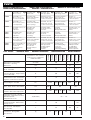 2
2
-
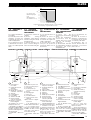 3
3
-
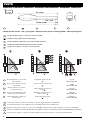 4
4
-
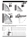 5
5
-
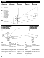 6
6
-
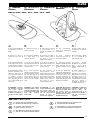 7
7
-
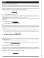 8
8
-
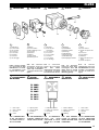 9
9
-
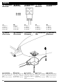 10
10
-
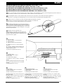 11
11
-
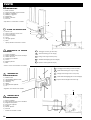 12
12
-
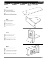 13
13
-
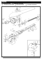 14
14
-
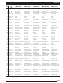 15
15
-
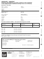 16
16


Nice Automation Pluto El manual del propietario
- Categoría
- Abridor de puerta
- Tipo
- El manual del propietario
en otros idiomas
Artículos relacionados
Otros documentos
-
Erreka EPEB Manual de usuario
-
Telcoma BLUES El manual del propietario
-
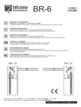 Telcoma Automations BR-6 El manual del propietario
-
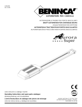 Beninca Aurora Super Guía del usuario
-
-
 RIB Prince 24V Plus Manual de usuario
-
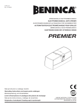 Beninca Premier El manual del propietario
-
-
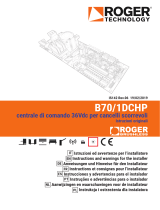 Roger Technology B70/1DCHP Manual de usuario
-
Beta 437K/33 Instrucciones de operación


