STIHL FS 300, 350, 380 El manual del propietario
- Categoría
- Podadoras de césped
- Tipo
- El manual del propietario

STIHL FS 300, 350, 380
Manual de instrucciones
Instruction Manual


Original de Instrucciones de
servicio
Impreso en papel blanqueado sin cloro.
Los colores de la impresión contienen aceites vegetales, por lo
que el papel es reciclable.
© ANDREAS STIHL AG & Co. KG, 2019
0458-579-8721-A. VA4.D19.
0000007358_006_E
FS 300, FS 350, FS 380
español
1
Este manual de instrucciones está protegido por derechos de autor. Nos reservamos todos los derechos, especialmente el
derecho a la reproducción, traducción y elaboración con sistemas electrónicos.
Índice
Distinguidos clientes:
Muchas gracias por haber depositado
su confianza en un producto de calidad
de la empresa STIHL.
Este producto se ha confeccionado con
modernos procedimientos de
fabricación y amplias medidas para
afianzar la calidad. Procuramos hacer
todo lo posible para que usted esté
satisfecho con este producto y pueda
trabajar con él sin problemas.
En el caso de que tenga usted alguna
pregunta sobre este producto, diríjase a
su distribuidor STIHL o directamente a
nuestra empresa de distribución.
Atentamente
Dr. Nikolas Stihl
Notas relativas a este manual de
instrucciones 2
Indicaciones relativas a la
seguridad y técnica de trabajo 2
Combinaciones permitidas de
herramienta de corte, protector,
tope y cinturón de porte 13
Montar la empuñadura doble 14
Ajustar el cable del acelerador 15
Acoplar los dispositivos de
protección 16
Montar la herramienta de corte 17
Combustible 22
Repostar combustible 23
Ponerse el cinturón de porte 24
Equilibrar la máquina 26
Arrancar / parar el motor 26
Transporte de la máquina 29
Indicaciones para el servicio 30
Filtro de aire 30
Ajustar el carburador 31
Bujía 32
Comportamiento de marcha del
motor 33
Lubricar el engranaje 33
Cambiar el cordón de arranque /
resorte de retracción 34
Guardar la máquina 36
Afilar herramientas de corte de
metal 36
Mantenimiento del cabezal de corte 37
Comprobación y mantenimiento por
el usuario 38
Comprobación y mantenimiento por
el distribuidor especializado 38
Instrucciones de mantenimiento y
conservación 39
Minimizar el desgaste y evitar
daños 41
Componentes importantes 42
Datos técnicos 43
Indicaciones para la reparación 45
Gestión de residuos 45
Declaración de conformidad UE 46

FS 300, FS 350, FS 380
español
2
Símbolos gráficos
Los símbolos gráficos existentes en la
máquina están explicados en este
manual de instrucciones.
En función de la máquina y el
equipamiento, pueden existir los
siguientes símbolos gráficos en la
máquina.
Marcación de párrafos de texto
ADVERTENCIA
Advertencia de peligro de accidente y
riesgo de lesiones para personas y de
daños materiales graves.
INDICACIÓN
Advertencia de daños de la máquina o
de diferentes componentes.
Perfeccionamiento técnico
STIHL trabaja permanentemente en el
perfeccionamiento de todas las
máquinas y dispositivos; por ello, nos
reservamos los derechos relativos a las
modificaciones del volumen de
suministro en la forma, técnica y
equipamiento.
De los datos e ilustraciones de este
manual de instrucciones no se pueden
deducir por lo tanto derechos a
reclamar.
Observar las normas de seguridad del
país, de p. ej. las Asociaciones
Profesionales del ramo, organismos
sociales y autoridades competentes
para asuntos de prevención de
accidentes en el trabajo y otras.
Al trabajar por primera vez con esta
máquina: dejar que el vendedor o un
experto le muestre cómo se maneja con
seguridad – o tomar parte en un cursillo
apropiado.
Los menores de edad no deberán
trabajar con esta máquina a motor – a
excepción de jóvenes de más de 16
años que estén aprendiendo bajo la
tutela de un instructor.
No dejar que se acerquen niños,
animales ni espectadores.
Notas relativas a este
manual de instrucciones
Depósito de combusti-
ble; mezcla de
combustible compuesta
por gasolina y aceite de
motor
Accionar la válvula de
descompresión
Bomba manual de
combustible
Accionar la bomba
manual de combustible
Tubo de grasa
Conducción del aire de
admisión: servicio de
verano
Conducción del aire de
admisión: servicio de
invierno
Calefacción de
empuñadura
Indicaciones relativas a la
seguridad y técnica de
trabajo
Será necesario observar
medidas de seguridad
especiales al trabajar con
esta máquina a motor
porque la herramienta de
corte trabaja a un número
de revoluciones muy
elevado.
Antes de ponerla en ser-
vicio por primera vez, leer
con atención todo el
manual de instrucciones
y guardarlo en un lugar
seguro para posteriores
consultas. La inobservan-
cia del manual de
instrucciones puede
tener consecuencias
mortales.

FS 300, FS 350, FS 380
español
3
Si la máquina no se utiliza, se deberá
colocar de forma que nadie corra
peligro. La máquina deberá ser
inaccesible para personas ajenas.
El usuario es el responsable de los
accidentes o peligros que afecten a
otras personas o sus propiedades.
Prestar o alquilar esta máquina
únicamente a personas que estén
familiarizadas con este modelo y su
manejo – entregarles siempre también
el manual de instrucciones.
El uso de máquinas a motor que emitan
ruidos puede estar limitado
temporalmente por disposiciones
nacionales o también comunales.
Para trabajar con esta máquina a motor,
se deberá estar descansado,
encontrarse bien y estar en buenas
condiciones.
Quien por motivos de salud no pueda
realizar esfuerzos, debería consultar
con su médico si puede trabajar con una
máquina a motor.
Sólo para implantados con marcapasos:
el sistema de encendido de esta
máquina genera un campo
electromagnético muy pequeño. No se
puede excluir por completo que influya
en algunos tipos de marcapasos. Para
evitar riesgos sanitarios,
STIHL recomienda que consulte a su
médico y al fabricante del marcapasos.
Tras la ingestión de bebidas alcohólicas,
medicamentos que disminuyan la
capacidad de reacción, o drogas, no se
debe trabajar con esta máquina a motor.
Emplear la máquina – en función de las
herramientas de corte asignadas –
únicamente para segar hierba así como
para cortar hierba silvestre, arbustos,
maleza, arbolitos o similares.
No se deberá utilizar la máquina para
otros fines – ¡peligro de accidente!
Acoplar únicamente herramientas de
corte o accesorios autorizados
por STIHL para esta máquina a motor o
piezas técnicamente equivalentes. Si
tiene preguntas al respecto, consulte a
un distribuidor especializado. Emplear
sólo herramientas o accesorios de gran
calidad. De no hacerlo, existe el riesgo
de que se produzcan accidentes o
daños en la máquina.
STIHL recomienda emplear
herramientas y accesorios
originales STIHL. Las propiedades de
éstos armonizan óptimamente con el
producto y las exigencias del usuario.
No realizar modificaciones en la
máquina – ello puede ir en perjuicio de la
seguridad. STIHL excluye cualquier
responsabilidad ante daños personales
y materiales que se produzcan al
emplear equipos de acople no
autorizados.
No emplear hidrolimpiadoras de alta
presión para limpiar la máquina. El
chorro de agua duro puede dañar piezas
de la máquina.
El protector de la máquina no puede
proteger al usuario contra todos los
objetos (piedras, cristal, alambre, etc.)
que pueda despedir la herramienta de
corte. Estos objetos pueden rebotar en
algún lugar y pegarle luego al usuario.
Ropa y equipo
Ponerse la ropa y el equipo
reglamentarios.
Sólo en el caso de utilizar cabezales de
corte, se admiten como alternativa
zapatos resistentes con suelas
adherentes a prueba de resbalamiento.
ADVERTENCIA
La ropa deberá ser apro-
piada y no estorbar.
Ponerse ropa ceñida –
traje combinado, no
abrigo de trabajo.
No ponerse ropa que se
pueda enganchar en la
madera, arbustos o pie-
zas de la máquina que
estén en movimiento.
Tampoco bufanda, cor-
bata ni artículos de
joyería. Recogerse el
pelo largo y sujetarlo (con
un pañuelo, gorra, casco,
etc.).
Ponerse botas protecto-
ras con suelas
adherentes y a prueba de
resbalamiento con cape-
ruza de acero.
Para reducir el peligro de
lesiones oculares,
ponerse unas gafas pro-
tectoras ceñidas según la
norma EN 166. Prestar
atención a que asienten
correctamente las gafas
protectoras.

FS 300, FS 350, FS 380
español
4
Ponerse un protector para la cara y
prestar atención a que asienten
correctamente. El protector de la cara
no es suficiente para proteger los ojos.
Ponerse un protector acústico
"personal" – p. ej. protectores de oídos.
Llevar casco protector al realizar
trabajos de aclareo forestal con maleza
alta y si hay peligro de que caigan
objetos.
STIHL ofrece una extensa gama de
equipamiento de protección personal.
Transporte de la máquina
Parar siempre el motor.
Llevar la máquina colgada del cinturón o
equilibrada por el vástago.
Asegurar la herramienta de corte de
metal contra el contacto con un
protector para el transporte, aunque se
trate de distancias cortas – véase
también "Transportar la máquina".
En vehículos: asegurar la máquina para
que no vuelque, no se dañe ni se
derrame combustible.
Repostaje
Parar el motor antes de repostar.
No repostar mientras el motor está aún
caliente – el combustible puede rebosar
– ¡peligro de incendio!
Abrir con cuidado el cierre del depósito
para que se reduzca lentamente la
presión y no despida combustible.
Repostar combustible sólo en lugares
bien ventilados. De haberse derramado
combustible, limpiar la máquina
inmediatamente – poner atención a que
la ropa no se moje con combustible; si
ello ocurriera, cambiársela
inmediatamente.
Así se reduce el riesgo de que se afloje
el cierre del depósito por las vibraciones
del motor y que salga combustible.
Fijarse en que no haya fugas – no
arrancar el motor si sale combustible –
¡peligro de muerte por quemaduras!
Antes de arrancar
Comprobar que el estado de la máquina
reúna condiciones de seguridad – tener
en cuenta los capítulos
correspondientes del manual de
instrucciones:
– Comprobar el sistema de
combustible en cuanto a
estanqueidad, especialmente las
piezas visibles como p. ej. el cierre
del depósito, las uniones de tubos
flexibles, la bomba manual de
combustible (sólo en caso de
máquinas equipadas con bomba
manual de combustible). En caso
de fugas o daños, no arrancar el
motor – ¡peligro de incendio! Antes
de poner en marcha la máquina,
llevarla a un distribuidor
especializado para su reparación
– La combinación de herramienta de
corte, protector, empuñadura y
cinturón de porte deberá estar
permitida y todas las piezas
deberán estar correctamente
montadas
Llevar guantes de trabajo
robustos de material
resistente (p. ej. de
cuero).
002BA079 KN
No tocar piezas calientes
de la máquina ni el
engranaje – ¡peligro de
quemaduras!
La gasolina se enciende
con muchísima facilidad
– guardar distancia res-
pecto de llamas – no
derramar combustible –
no fumar.
Después de repostar,
apretar el cierre roscado
del depósito lo más firme-
mente posible.

FS 300, FS 350, FS 380
español
5
– El cursor del mando
unificado/interruptor de parada se
pueden poner con facilidad
en STOP o bien 0
– El acelerador y el bloqueo del
mismo se deberán mover con
suavidad – el acelerador debe
volver automáticamente a la
posición de ralentí
– Comprobar que esté firme el
enchufe del cable de encendido – si
está flojo, pueden producirse
chispas que enciendan la mezcla
de combustible y aire que salga –
¡peligro de incendio!
– Herramienta de corte o herramienta
de acople: montaje correcto,
asiento firme y estado perfecto
– Comprobar los dispositivos de
protección (p. ej. el protector de la
herramienta de corte, plato de
rodadura) en cuanto a daños o bien
desgaste. Renovar las piezas que
estén dañadas. No utilizar la
máquina estando dañado el
protector o con el plato de rodadura
desgastado (si el rotulado y las
flechas ya no son visibles)
– No modificar los dispositivos de
mando ni los de seguridad
– Las empuñaduras tienen que estar
limpias y secas, libres de aceite y
suciedad – esto es importante para
manejar la máquina de forma
segura
– Ajustar el cinturón de porte y la(s)
empuñadura(s) con arreglo a la
estatura. Tener en cuenta los
capítulos "Ponerse el cinturón de
porte" – "Equilibrar la máquina"
La máquina sólo se deberá utilizar si
reúne condiciones de seguridad para el
trabajo – ¡peligro de accidente!
Para casos de emergencia al utilizar
cinturones de porte: practicar la
deposición rápida de la máquina. Al
practicar, no arrojar la máquina al suelo,
a fin de evitar que se dañe.
Arrancar el motor
Al menos a 3 m del lugar donde se ha
repostado – no hacerlo en lugares
cerrados.
Hacerlo sólo sobre terreno llano,
adoptar una postura estable y segura,
sujetar la máquina de forma segura – la
herramienta de corte no deberá tocar
objeto alguno ni el suelo, ya que puede
empezar a girar al arrancar.
El manejo de la máquina lo efectúa una
sola persona – no tolerar la presencia de
otras personas en un círculo de 15 m –
tampoco durante el arranque – ¡peligro
de lesiones! por objetos despedidos
Comprobar el ralentí: la herramienta de
corte debe estar parada en ralentí –
estando el acelerador en reposo.
Mantener apartados materiales
fácilmente inflamables (p. ej. virutas de
madera, cortezas de árbol, hierba seca,
combustible) de la corriente caliente de
gases de escape y de la superficie
caliente del silenciador – ¡peligro de
incendio!
Sujeción y manejo de la máquina
Sujetar siempre la máquina con ambas
manos por las empuñaduras.
Adoptar siempre una postura estable y
segura.
En ejecuciones de empuñadura doble
La mano derecha, en la empuñadura de
mando; la mano izquierda, en la
empuñadura del asidero tubular.
Evitar el contacto con la
herramienta de corte –
¡peligro de lesiones!
No arrancar el motor con
la máquina suspendida
de la mano – hacerlo tal
como se describe en el
manual de instrucciones.
Las cuchillas siguen fun-
cionando todavía un
momento tras soltar el
acelerador – ¡efecto de
inercia!
002BA055 KN

FS 300, FS 350, FS 380
español
6
En ejecuciones de asidero tubular
cerrado
En ejecuciones de asidero tubular
cerrado y asidero tubular cerrado con
estribo (limitador de paso), la mano
izquierda, en el asidero tubular cerrado;
la derecha, en la empuñadura de mando
– también al tratarse de zurdos.
Durante el trabajo
Adoptar siempre una postura estable y
segura.
En caso de peligro inminente, o bien de
emergencia, parar inmediatamente el
motor – poner el cursor del mando
unificado / el interruptor de parada
en STOP o 0.
En un amplio círculo en torno al lugar de
trabajo puede existir un peligro de
accidente originado por objetos
despedidos, por lo que no se deberá
permitir la presencia de otras personas
en un círculo de 15 m. Mantenerse a
esta distancia también respecto de
objetos (vehículos, ventanas) – ¡peligro
de daños materiales! También a una
distancia de más de 15 m no se puede
excluir que exista peligro.
Prestar atención a que el ralentí sea
perfecto, a fin de que deje de girar la
herramienta de corte al soltar el
acelerador.
Controlar o bien corregir periódicamente
el ajuste del ralentí. Si pese a ello se
mueve la herramienta de corte en
ralentí, encargar la reparación a un
distribuidor especializado. STIHL
recomienda un distribuidor
especializado STIHL.
Prestar atención en caso de que el suelo
esté congelado, mojado, nevado, en
pendientes y terrenos irregulares, etc. –
¡peligro de resbalar!
Prestar atención a los obstáculos:
tocones, raíces – ¡peligro de tropezar!
Trabajar sólo estando de pie en el suelo,
no hacerlo nunca en lugares inestables,
jamás sobre escaleras o desde una
plataforma elevadora.
Al llevar un protector para los oídos, hay
que prestar más atención y tener más
precaución – se perciben peor las
señales de aviso de peligro (gritos,
señales acústicas y similares).
Hacer siempre oportunamente pausas
en el trabajo para prevenir el cansancio
y el agotamiento – ¡peligro de accidente!
Trabajar con tranquilidad y prudencia –
sólo en buenas condiciones de luz y
visibilidad. Trabajar con precaución, no
poner en peligro a otras personas.
Al trabajar en zanjas, fosas o espacios
reducidos, se ha de procurar que haya
siempre suficiente ventilación – ¡peligro
de muerte por intoxicación!
En caso de malestar, dolores de
cabeza, dificultades de visión
(p. ej. reducción del campo visual),
problemas de audición, mareos y
pérdida de concentración, dejar de
trabajar inmediatamente – estos
síntomas se pueden producir, entre
otras causas, por una concentración de
gases de escape demasiado alta –
¡peligro de accidente!
Trabajar con la máquina tratando de
hacer poco ruido y acelerando poco – no
dejar innecesariamente el motor en
marcha, dar gas sólo para trabajar.
No fumar trabajando con la máquina ni
en el entorno inmediato de la misma –
¡peligro de incendio! Del sistema de
combustible pueden salir vapores de
gasolina inflamables.
El polvo, la neblina y el humo que se
generan al trabajar pueden ser nocivos
para la salud. Ponerse una mascarilla si
se produce mucho polvo o humo.
002BA080 KN
15m (50ft)
La máquina produce
gases de escape tóxicos
en cuanto el motor está
en marcha. Estos gases
puede que sean inodoros
e invisibles pero pueden
contener hidrocarburos y
benceno sin quemar. No
trabajar nunca con la
máquina en locales
cerrados o con poca ven-
tilación – tampoco con
máquinas equipadas con
catalizador.

FS 300, FS 350, FS 380
español
7
En el caso de que la máquina haya
sufrido percances para los que no está
prevista (p. ej., golpes o caídas), se ha
de comprobar sin falta que funcione de
forma segura antes de continuar el
trabajo – véase también "Antes de
arrancar".
Comprobar en especial la estanqueidad
del sistema de combustible y la
operatividad de los dispositivos de
seguridad. De ningún modo se deberá
seguir trabajando con máquinas que ya
no sean seguras. En caso de dudas,
consultar a un distribuidor
especializado.
No trabajar con gas de arranque – el
régimen del motor no se puede regular
estando el acelerador en esta posición.
Trabajar con especial precaución en
terrenos de poca visibilidad y con mucha
vegetación.
Al segar zarzales altos, por debajo de
matorrales y setos: la altura de trabajo
con la herramienta de corte deberá ser
al menos de 15 cm – no poner en peligro
los animales.
Parar el motor antes de ausentarse de la
máquina.
Comprobar la herramienta de corte, a
intervalos breves y hacerlo
inmediatamente si se percibe algún
cambio:
– Parar el motor, sujetar la máquina
de forma segura y dejar que se
detenga la herramienta de corte
– Revisar el estado y asiento firme,
prestar atención a las fisuras
– Fijarse en el estado de afilado
– Cambiar inmediatamente las
herramientas de corte dañadas o
embotadas, incluso en el caso de
fisuras capilares insignificantes
Limpiar regularmente el alojamiento de
la herramienta de corte de restos de
hierba y maleza – quitar las
obstrucciones de la zona de la
herramienta de corte o del protector.
Para cambiar la herramienta de corte,
parar el motor – ¡peligro de lesiones!
Utilización de cabezales de corte
Completar el protector de la herramienta
de corte con las piezas de acople
indicadas en el manual de instrucciones.
Emplear sólo un protector con la cuchilla
debidamente montada, a fin de que los
hilos de corte se limiten a la longitud
admisible.
Para reajustar el hilo en cabezales de
corte de reajuste manual, parar sin falta
el motor – ¡peligro de lesiones!
El uso indebido de la máquina con hilos
demasiado largos reduce el número de
revoluciones de trabajo del motor.
Debido al permanente resbalamiento
del embrague que ello origina, se
produce un calentamiento excesivo y la
avería de piezas importantes (como
p. ej., el embrague, piezas de la carcasa
de plástico) – ¡peligro de lesiones! por
ejemplo, por girar la herramienta de
corte en ralentí.
Empleo de herramientas de corte de
metal
STIHL recomienda emplear únicamente
herramientas de corte de metal
originales STIHL. Las propiedades de
éstas están armonizadas óptimamente
con la máquina y las exigencias del
usuario.
Las herramientas de corte de metal
giran con mucha rapidez. Al hacerlo, se
generan fuerzas que actúan sobre la
máquina, la herramienta misma y el
material objeto de corte.
No trabajar nunca
sin el protector
apropiado para la
máquina y la herra-
mienta de corte –
¡peligro de
lesiones!
Inspeccionar el terreno:
pueden salir despedidos
objetos sólidos – pie-
dras, piezas de metal o
similares – también por
encima de 15 m – ¡peli-
gro de lesiones! – y
pueden dañar la herra-
mienta de corte así como
otros objetos
(p. ej. vehículos aparca-
dos, cristales de
ventanas) (daños
materiales).
El engranaje se calienta
durante el trabajo. No
tocar el engranaje – ¡peli-
gro de quemaduras!

FS 300, FS 350, FS 380
español
8
Las herramientas de corte de metal se
han de afilar periódicamente según las
prescripciones.
Las herramientas de corte de metal
afiladas desigualmente provocan un
desequilibrio, que puede cargar
extremadamente la máquina – ¡peligro
de rotura!
Los filos romos o indebidamente
afilados pueden originar un alto
esfuerzo de la herramienta de corte de
metal – ¡peligro de lesiones! por las
piezas rajadas o rotas
Revisar la herramienta de corte de metal
cada vez que tope con objetos duros
(p. ej. piedras, rocas, piezas de metal)
(p. ej. en cuanto a fisuras y
deformaciones). Las rebabas y otros
recrecimientos de material visibles se
han de quitar (lo mejor es hacerlo con
una lima), dado que se pueden soltar en
el transcurso del trabajo y salir
despedidos – ¡peligro de lesiones!
Si una herramienta de corte de metal en
giro topa en una piedra u otro objeto
duro, pueden generarse chispas por lo
que, en determinadas circunstancias
pueden encenderse materiales que
sean fácilmente inflamables. También
las plantas y maleza en estado seco son
fácilmente inflamables, especialmente
en condiciones meteorológicas de
mucho calor y sequedad. Si existe
peligro de incendio, no emplear
herramientas de corte de metal cerca de
sustancias fácilmente inflamables,
plantas secas o maleza. Preguntar sin
falta a la autoridad forestal competente
si existe peligro de incendio.
No seguir utilizando herramientas de
corte que estén dañadas o agrietadas ni
repararlas – soldándolas o
enderezándolas – deformaciones
(desequilibrio).
Las partículas o piezas rotas pueden
soltarse y alcanzar a gran velocidad al
usuario u otras personas – ¡y originar las
más graves lesiones!
Para reducir los peligros mencionados
que se generan durante el
funcionamiento de una herramienta de
corte de metal, la herramienta empleada
no deberá tener de ningún modo un
diámetro demasiado grande ni deberá
pesar demasiado. Tiene que estar
fabricada con materiales de calidad
suficiente y tener una geometría
apropiada (forma, espesor).
Una herramienta de corte de metal que
no haya sido fabricada por STIHL no
deberá pesar más, ni ser más gruesa, ni
tener una conformación diferente ni un
diámetro superior al de la herramienta
de corte de metal STIHL más grande
permitida para esta máquina a motor –
¡peligro de lesiones!
Vibraciones
La utilización prolongada de la máquina
puede provocar trastornos circulatorios
en las manos ("enfermedad de los
dedos blancos") originados por las
vibraciones.
No se puede establecer una duración
general del uso, porque ésta depende
de varios factores que influyen en ello.
El tiempo de uso se prolonga:
– Protegiendo las manos (guantes
calientes)
– Haciendo pausas
El tiempo de uso se acorta por:
– La predisposición personal a una
mala circulación sanguínea
(síntomas: dedos fríos con
frecuencia, hormigueo)
– Bajas temperaturas
– Magnitud de la fuerza de sujeción
(la sujeción firme dificulta el riego
sanguíneo)
En el caso trabajar con regularidad y
durante mucho tiempo con la máquina y
manifestarse repetidamente tales
síntomas (p. ej. hormigueo en los
dedos), se recomienda someterse a un
examen médico.
Mantenimiento y reparaciones
Efectuar con regularidad los trabajos de
mantenimiento de la máquina. Efectuar
únicamente trabajos de mantenimiento
y reparaciones que estén descritos en el
manual de instrucciones. Encargar
todos los demás trabajos a un
distribuidor especializado.
STIHL recomienda encargar los
trabajos de mantenimiento y las
reparaciones siempre a un distribuidor
especializado STIHL. Los distribuidores
especializados STIHL siguen
periódicamente cursillos de instrucción
y tienen a su disposición las
informaciones técnicas.

FS 300, FS 350, FS 380
español
9
Emplear sólo repuestos de gran calidad.
De no hacerlo, existe el peligro de que
se produzcan accidentes o daños en la
máquina. Si tiene preguntas al respecto,
consulte a un distribuidor especializado.
STIHL recomienda emplear piezas de
repuesto originales STIHL. Las
propiedades de éstas están
armonizadas óptimamente con la
máquina y las exigencias del usuario.
Para la reparación, el mantenimiento y
la limpieza, parar siempre el motor -
¡peligro de lesiones! - Excepción: ajuste
del carburador y el ralentí.
Estando desacoplado el enchufe del
cable de encendido o con la bujía
desenroscada, poner en movimiento el
motor con el dispositivo de arranque
únicamente si el cursor del mando
unificado / interruptor de parada se
encuentra en STOP o bien 0 – peligro de
incendio por chispas de encendido fuera
del cilindro.
No realizar trabajos de mantenimiento
en la máquina ni guardar ésta cerca de
fuego abierto – peligro de incendio
debido al combustible.
Comprobar periódicamente la
estanqueidad del cierre del depósito.
Emplear únicamente bujías en perfecto
estado, autorizadas por STIHL – véase
"Datos técnicos".
Inspeccionar el cable de encendido
(aislamiento perfecto, conexión firme).
Comprobar con regularidad el
silenciador en cuanto a perfecto estado.
No trabajar estando dañado el
silenciador ni sin éste – ¡peligro de
incendio! – ¡daños en los oídos!
No tocar el silenciador si está caliente –
¡peligro de quemaduras!
El estado de los elementos
antivibradores influye en el
comportamiento de vibración – controlar
con regularidad dichos elementos.
Símbolos en los dispositivos de
protección
Una flecha en el protector para las
herramientas de corte indica el sentido
de giro de las mismas.
Cinturón de porte
El cinturón de porte está contenido en el
volumen de suministro o se puede
adquirir como accesorio especial.
N Usar el cinturón de porte
N Enganchar la máquina en el
cinturón de porte con el motor en
marcha
Los cabezales de corte y las cuchillas
cortamalezas se han de usar en
combinación con un cinturón sencillo o
un cinturón doble como cinturón de
porte
Las cuchillas trituradoras se han de usar
en combinación con un cinturón de porte
doble.
Las hojas de sierra circular se han de
usar en combinación con un cinturón
doble provisto de dispositivo de soltado
rápido.
Cabezal de corte con hilo de corte
Para un "corte" suave y blando – para
cortar nítidamente también bordes
resquebrajados en torno a árboles y
postes de vallas, etc. – se lesiona
menos la corteza del árbol.
Emplear el protec-
tor sólo en
combinación con
cabezales de corte
– no hacerlo con
herramientas de
corte de metal.
002BA364 KN
000BA015 KN

FS 300, FS 350, FS 380
español
10
En el volumen de suministro del cabezal
de corte existe una hoja de
instrucciones adjuntada. Poner el hilo en
el cabezal de corte sólo según las
indicaciones contenidas en la hoja de
instrucciones.
ADVERTENCIA
No sustituir el hilo de corte por alambres
o cuerdas – ¡peligro de lesiones!
Cabezal de corte con cuchillas de
plástico – STIHL PolyCut
Para segar bordes de prados silvestres
(sin postes, vallas, árboles ni obstáculos
similares).
¡Tener en cuenta las marcas de
desgaste!
Si se ha roto una de las marcas del
cabezal de corte PolyCut hacia abajo
(flecha): no volver a utilizar el cabezal de
corte y sustituirlo por uno nuevo.
¡Peligro de lesiones por piezas de la
herramienta despedidas!
Observar sin falta las indicaciones de
mantenimiento para el cabezal de corte
PolyCut.
En lugar de las cuchillas de plástico, se
puede poner también hilo en el cabezal
de corte PolyCut.
En el volumen de suministro del cabezal
de corte existen hojas de instrucciones
adjuntadas. Poner cuchillas de plástico
o hilo en el cabezal de corte sólo según
las indicaciones contenidas en las hojas
de instrucciones.
ADVERTENCIA
No poner alambres o cuerdas en lugar
del hilo de corte – ¡peligro de lesiones!
Peligro de rebote en el caso de
herramientas de corte de metal
ADVERTENCIA
Existe un riesgo de rebote aumentado
cuando la herramienta incide en un
obstáculo por el sector negro.
Cuchilla cortamalezas
Para cortar hierba enredada, aclarar
hierba silvestre y matorrales y para el
aclareo de arboleda joven con un
diámetro de tronco de máximo 2 cm – no
cortar madera más gruesa – ¡peligro de
accidente!
Al cortar hierba y aclarar arboleda joven,
guiar la máquina como una guadaña,
manteniendo la herramienta muy cerca
del suelo.
Para aclarar hierba silvestre y
matorrales, "sumergir" la cuchilla
cortamalezas desde arriba en las
plantas – con ello se tritura todo – al
hacerlo, no sostener la herramienta de
corte a una altura superior a las
caderas.
Con esta técnica de trabajo se requiere
máxima atención. Cuanto mayor es la
distancia de la herramienta de corte
002BA396 KN
Al trabajar con herra-
mientas de corte de
metal, existe el peligro de
rebote cuando la herra-
mienta incide en un
obstáculo sólido (el
tronco de un árbol, rama,
tocón, piedra o algo simi-
lar). La máquina es
lanzada entonces hacia
atrás – en sentido contra-
rio al del giro de la
herramienta.
002BA135 KN
002BA355 KN
002BA509 KN

FS 300, FS 350, FS 380
español
11
respecto del suelo, tanto mayor es el
riesgo de que se despidan partículas
hacia los lados – ¡peligro de lesiones!
Atención: El uso inapropiado puede
dañar la cuchilla cortamalezas – ¡peligro
de lesiones! por piezas despedidas
Para disminuir el riesgo de accidente,
tener en cuenta sin falta lo siguiente:
– Evitar el contacto con piedras,
cuerpos de metal o similares
– No cortar madera o matorrales de
un diámetro superior a 2 cm –
emplear una hoja de sierra circular
para diámetros más grandes
– Controlar periódicamente la cuchilla
cortamalezas en cuanto a daños –
no seguir utilizando la cuchilla
cortamalezas si está dañada
– Afilar periódicamente la cuchilla
cortamalezas, si se percibe su
embotamiento, según las
prescripciones y – de ser necesario
– equilibrarla (STIHL recomienda
acudir a un distribuidor
especializado STIHL)
Cuchilla trituradora
Para aclarar y recepar hierba resistente
y enredada, hierba silvestre y
matorrales.
Para aclarar y recepar hierba silvestre y
matorrales, "sumergir" la cuchilla
trituradora desde arriba en las plantas –
con ello se tritura todo – al hacerlo, no
sostener la herramienta de corte a una
altura superior a las caderas.
Con esta técnica de trabajo se requiere
máxima atención. Cuanto mayor es la
distancia de la herramienta de corte
respecto del suelo, tanto mayor es el
riesgo de que se despidan partículas
hacia los lados – ¡peligro de lesiones!
Atención: El uso inapropiado puede
dañar la cuchilla trituradora – ¡riesgo de
lesiones! por piezas despedidas
Para disminuir el riesgo de accidente,
tener en cuenta sin falta lo siguiente:
– Evitar el contacto con piedras,
cuerpos de metal o similares
– No cortar madera o matorrales de
un diámetro superior a 2 cm –
emplear una hoja de sierra circular
para diámetros más grandes
– Controlar periódicamente la cuchilla
trituradora en cuanto a daños – no
seguir utilizando la cuchilla
trituradora si está dañada
– Afilar periódicamente la cuchilla
trituradora, si se percibe su
embotamiento, según las
prescripciones y – de ser necesario
– equilibrarla (STIHL recomienda
acudir a un distribuidor
especializado STIHL)
Hoja de sierra circular
Para cortar matorrales y árboles de
hasta 7 cm de diámetro de tronco.
El mejor rendimiento de corte se obtiene
a pleno gas y con una presión de
avance uniforme.
Emplear las hojas de sierra circular sólo
con el tope apropiado para el diámetro
de la herramienta de corte.
ADVERTENCIA
Se deberá evitar sin falta el contacto de
la hoja de sierra circular con piedras y
tierra – existe el peligro de que se
formen grietas. Afilar la herramienta a
tiempo y según las prescripciones – los
dientes romos pueden provocar la
formación de grietas y, con ello, la rotura
de la hoja de sierra – ¡peligro de
accidente!
Al talar, mantener una distancia de al
menos dos veces la longitud del árbol
respecto del lugar de trabajo más
cercano.
002BA210 KN

FS 300, FS 350, FS 380
español
12
Peligro de rebote
El peligro de rebote es muy alto en el
sector negro: en este sector no se
deberá aplicar nunca la hoja para serrar
ni se deberá cortar nada.
En el sector gris existe también riesgo
de rebote: este sector lo pueden utilizar
únicamente personas con experiencia y
formación especial en técnicas de
trabajo especiales.
En el sector blanco se puede trabajar
con bajo nivel de rebote y con facilidad.
Aplicar la herramienta siempre en este
sector para cortar.
002BA449 KN

FS 300, FS 350, FS 380
español
13
Combinaciones permitidas de herramienta de corte, protector, tope y cinturón de porte
Herramienta de corte Protector, tope Cinturón de porte
11
0000-GXX-0378-A1
2
3
6
7
9
12
14
1
4
8
10
15
5
13
18
16 17

FS 300, FS 350, FS 380
español
14
Combinaciones permitidas
En función de la herramienta de corte,
seleccionar la combinación correcta de
la tabla.
ADVERTENCIA
Por motivos de seguridad, únicamente
se permite combinar entre sí las
herramientas de corte y protectores o
topes que se encuentren dentro de una
fila de la tabla. No se permiten otras
combinaciones: ¡peligro de accidente!
Herramientas de corte
Cabezales de corte
1 STIHL TrimCut 41-2
2 STIHL PolyCut 41-3
Herramientas de corte de metal
3 Cuchilla cortamalezas 305-
2 Spezial
(Ø 305 mm)
4 Cuchilla cortamalezas 300-3
(Ø 300 mm)
5 Cuchilla trituradora 270-2
(Ø 270 mm)
6 Hoja de sierra circular 200, dientes
en pico
(Ø 200 mm)
7 Hoja de sierra circular 200-22 diente
de cincel (4119), hoja de sierra
circular 200-22 HP diente de cincel
(4000)
8 Hoja de sierra circular 225, dientes
en cincel
(Ø 225 mm)
ADVERTENCIA
No se permiten cuchillas cortamalezas,
cuchillas trituradoras y hojas de sierra
circular de otros materiales que no sean
metal.
Protectores, topes
Protectores
9 Protector solo para cabezales de
corte
10 Protector con
11 Protector y cuchilla solo para
cabezales de corte
12 Protector sin faldón y cuchilla para
todas las herramientas de corte,
posiciones 3, 4
13 Protector para cuchillas para triturar
Topes
14 Tope para hojas de sierra circular
de 200 mm de diámetro
15 Tope para hojas de sierra circular
de 225 mm de diámetro
Cinturones de porte
16 Se tiene que emplear un cinturón
sencillo
17 Se puede emplear un cinturón
doble
18 Se tiene que emplear un cinturón
doble
N Sujetar la placa de apriete
inferior (1)
N Desenroscar el tornillo de
apriete (2) y quitarlo – las placas de
apriete quedan sueltas tras
desenroscar el tornillo
N Quitar la placa de sujeción
superior (3) de la placa inferior
Montar la empuñadura doble
3
1
2
256BA001 KN

FS 300, FS 350, FS 380
español
15
N Colocar el asidero tubular (4) en la
placa de apriete inferior (1), de
manera que la distancia (A) no sea
superior a 15 cm
N Colocar la placa de apriete superior
y oprimirla hacia abajo
N Enroscar el tornillo de apriete
N Ajustar el asidero tubular de forma
transversal respecto del vástago
N Apretar el tornillo de apriete
N Desenroscar el tornillo (5); al
hacerlo, la tuerca (6) permanece en
la empuñadura de mando (7)
N Montar la empuñadura de mando
en el extremo del asidero tubular (4)
con el acelerador (8) orientado
hacia el engranaje, hasta que
queden alineados los orificios (9)
N Enroscar el tornillo y apretarlo
N Proseguir con "Ajustar el cable del
acelerador"
Para ahorrar espacio en el transporte y
para el almacenamiento: aflojar el
tornillo de apriete, poner el asidero
tubular paralelo respecto del vástago y
girar las empuñaduras hacia abajo
Tras el montaje de la máquina o tras un
tiempo de funcionamiento largo de la
máquina, puede resultar necesario
corregir el ajuste del cable del
acelerador.
Ajustar el cable del acelerador sólo
estando montada la máquina completa.
N Poner el acelerador en la posición
de pleno gas
N Enroscar el tornillo en el acelerador
hasta percibir una resistencia,
procediendo en sentido de la flecha
Seguir enroscándolo luego media
vuelta más
A
4
1
256BA002 KN
9
5
7
8
4
9
002BA256 KN
6
7
Ajustar el cable del
acelerador
002BA655 KN

FS 300, FS 350, FS 380
español
16
Emplear el protector correcto
ADVERTENCIA
El protector (1) está autorizado sólo
para cabezales de corte, por lo que se
deberá montar el protector (1) antes de
montar un cabezal de corte.
ADVERTENCIA
El protector (2) sólo está autorizado
para cuchillas cortamalezas, por lo que
antes de montar una cuchilla
cortamalezas se deberá montar el
protector (2).
ADVERTENCIA
El protector (2) se permite también para
cabezales de corte si se montan el
faldón y la cuchilla; véase "Montar el
faldón y la cuchilla".
ADVERTENCIA
El protector (3) sólo está autorizado
para cuchillas trituradoras, por lo que se
deberá montar el protector (3) antes de
montar una cuchilla trituradora.
ADVERTENCIA
El tope (4) que sirve de protección sólo
está autorizado para hojas de sierra
circular, por lo que se deberá montar el
tope (4) y cambiar el anillo protector (5)
antes de montar una hoja de sierra
circular; véase "Montar la herramienta
de corte" / "Hojas de sierra circular".
Montar el protector
Los protectores (1 hasta 4) se fijan del
mismo modo al engranaje.
N Eliminar la suciedad de los puntos
de ensamblaje en el engranaje y en
el protector – no dejar que penetre
suciedad alguna en los orificios
roscados del engranaje
N Colocar el protector sobre el
engranaje (6),
N Enroscar los tornillos (7) y
apretarlos
Acoplar los dispositivos de
protección
002BA513 KN
1
002BA514 KN
2
002BA515 KN
2
002BA516 KN
3
002BA517 KN
4
5
002BA520 KN
6
7

FS 300, FS 350, FS 380
español
17
Montar el faldón
En caso de emplear cabezales de corte
En caso de montar cabezales de corte,
el protector para herramientas de segar
de metal (1) tiene que estar equipado
con el faldón (2).
N Calar la ranura de guía (3) inferior
del faldón (2) en la regleta del
protector (1) hasta que encastre
Montar la cuchilla
En caso de emplear cabezales de corte
de hilo
En caso de montar cabezales de corte
de hilo, el protector para herramientas
de segar de metal (1) tiene que estar
equipado con la cuchilla (4).
N Calar la cuchilla (4) en la ranura de
guía superior (5) del faldón (2) y
hacerla coincidir con el primer
orificio de fijación
N Enroscar el tornillo y apretarlo
Depositar la máquina
N Parar el motor
N Depositar la máquina, de manera
que el alojamiento para la
herramienta de corte esté orientado
hacia arriba
Piezas de fijación
En función de la herramienta de corte
suministrada en el equipamiento básico
de una máquina nueva, puede variar
también el volumen de suministro de
piezas de fijación.
Las piezas de fijación están montadas
en el engranaje para el transporte y se
han de desmontar antes de montar la
herramienta de corte.
2
1
3
2
002BA526 KN
1
4
002BA527 KN
5
1
4
1
2
Montar la herramienta de
corte
002BA406 KN

FS 300, FS 350, FS 380
español
18
Desmontar las piezas de fijación
N Bloquear el árbol
N Aflojar la tuerca (2) con la llave
universal (1) en el sentido horario y
quitarla
N Según el equipamiento, quitar el
plato de rodadura (3) y el disco de
presión (4)
Comprobar el plato de presión
El plato de presión es necesario para
fijar todas las herramientas de corte al
engranaje.
El plato de presión se compone del
cubo (1) y un disco protector (2)
montado encima de forma imperdible.
ADVERTENCIA
No emplear nunca el plato de presión
sin el disco protector. Los platos de
presión sin disco protector se han de
sustituir inmediatamente.
Montar el anillo protector
Según la herramienta de corte
empleada, se ha de utilizar el anillo
protector apropiado.
Los siguientes anillos protectores están
montados en el engranaje o se pueden
adquirir como accesorio especial:
Anillo protector para trabajos de siega
Para la protección óptima contra el
arrollamiento al trabajar con cuchillas
cortamalezas y cuchillas trituradoras
N Montar el anillo protector (1) para
trabajos de siega
N Colocar el plato de presión (2) y el
disco protector (3)
002BA295 KN
1
2
3
4
1
2
1
681BA196 KN
2
2
1
3
002BA524 KN

FS 300, FS 350, FS 380
español
19
Anillo protector para trabajos de
aserrado
Para trabajar con hojas de sierra circular
N Montar el anillo protector (1) para
trabajos de aserrado
N Colocar el plato de presión (2)
Limpiar el engranaje y las piezas de
fijación para la herramienta de corte
Comprobar periódicamente si hay
suciedad en el engranaje, en su
entorno, en la zona interior del protector
contra el arrollamiento y las distintas
piezas de fijación para la herramienta de
corte o, en caso de cambiar la
herramienta de corte y, si es necesario,
realizar una limpieza esmerada; para
ello:
N Retirar del engranaje todas las
piezas de fijación para la
herramienta de corte
Bloquear el árbol
N Aplicar hasta el tope el pasador (1)
al orificio (2) existente en el
engranaje – presionarlo ligeramente
N Girar el árbol hasta que encastre el
pasador
Montar la herramienta de corte
ADVERTENCIA
Emplear el protector apropiado para la
herramienta de corte – véase "Montar
los dispositivos de protección".
Montar el cabezal de corte con
empalme roscado
Guardar bien la documentación relativa
al cabezal de corte.
Transformar el cabezal de corte a una
conexión roscada cambiable
N Comprobar si hay montada en el
cabezal de corte una tuerca con
collar (1) con una rosca interior
M12
Si hay montada una tuerca con collar
con una rosca M 14:
N Desmontar una tuerca con collar
con una rosca M 14 y sustituirla por
una ejecución M 12 – véase
indicaciones para la transformación
en la documentación relativa al
cabezal de corte
2
1
002BA525 KN
1
2
002BA294 KN
M 14 M 12
681BA290 KN
PolyCut 41 - 3
1

FS 300, FS 350, FS 380
español
20
Montar el cabezal de corte
N Girar el cabezal de corte en sentido
antihorario en el árbol (2) hasta el
tope
N Bloquear el árbol
N Apretar el cabezal de corte
INDICACIÓN
Volver a quitar la herramienta de
bloquear el árbol.
Desmontar el cabezal de corte
N Bloquear el árbol
N Girar el cabezal de corte en sentido
horario
Montar y desmontar herramientas de
corte de metal
Guardar bien la hoja de instrucciones
adjuntada y el embalaje de la
herramienta de corte de metal.
ADVERTENCIA
Ponerse guantes protectores – peligro
de lesiones por filos de corte afilados
Montar siempre sólo una herramienta de
corte de metal
Cuchilla cortamalezas
Colocar correctamente la herramienta
de corte
Los filos de corte de la cuchilla
cortamalezas de 2 ó 3 hojas pueden
estar orientados en cualquier sentido.
Darle la vuelta regularmente a la
herramienta de corte a fin de evitar un
desgaste unilateral.
Montar la herramienta de corte
N Montar el anillo protector para
trabajos de corte
N Colocar la herramienta de corte (1)
ADVERTENCIA
El collar (a) tiene que penetrar en el
orificio (b) de la herramienta de corte.
Fijar la herramienta de corte
N Colocar el disco de presión (2) – el
abombado, hacia arriba
N Colocar el plato de rodadura (3)
para el trabajo de siega
N Bloquear el árbol
N Girar la tuerca (4) en sentido
antihorario en el árbol y apretarla
firmemente
ADVERTENCIA
Sustituir la tuerca si gira con demasiada
facilidad.
2
681BA292 KN
681BA123 KN
002BA521 KN
b
2
3
1
4
a

FS 300, FS 350, FS 380
español
21
INDICACIÓN
Retirar la herramienta de bloquear el
árbol.
Desmontar la herramienta de corte
N Bloquear el árbol
N Aflojar la tuerca en sentido horario
N Retirar del engranaje la herramienta
de corte y sus piezas de fijación
Cuchilla trituradora 270-2
Montar la herramienta de corte
N Montar el anillo protector para
trabajos de corte
N Colocar la cuchilla trituradora (1),
las aristas de corte tienen que estar
orientadas hacia arriba
ADVERTENCIA
El collar (a) tiene que penetrar en el
orificio (b) de la herramienta de corte.
Fijar la herramienta de corte
N Colocar el disco de presión (2) – el
abombado, hacia arriba
N Colocar el anillo protector (3)
N Bloquear el árbol
N Girar la tuerca (4) en sentido
antihorario en el árbol y apretarla
firmemente
ADVERTENCIA
Sustituir la tuerca si gira con demasiada
facilidad.
INDICACIÓN
Retirar la herramienta de bloquear el
árbol.
Desmontar la herramienta de corte
N Bloquear el árbol
N Aflojar la tuerca en sentido horario
N Retirar del engranaje la herramienta
de corte y sus piezas de fijación
Hojas de sierra circular 200 y 225
Colocar correctamente la herramienta
de corte
En las hojas cortahierbas (3), las aristas
de corte tienen que estar orientadas en
sentido horario.
Montar la herramienta de corte
N Montar el anillo protector para
trabajos de siega
N Colocar la herramienta de corte (1)
a
1
002BA522 KN
3
4
2
b
3
b
681BA165 KN
b
002BA300 KN
3
4
1
2
a

FS 300, FS 350, FS 380
español
22
ADVERTENCIA
El collar (a) tiene que penetrar en el
orificio (b) de la herramienta de corte.
Fijar la herramienta de corte
N Colocar el disco de presión (2) – el
abombado, hacia arriba
N Colocar el plato de rodadura (3)
para el trabajo de aserrado
N Bloquear el árbol
N Girar la tuerca (4) en sentido
antihorario en el árbol y apretarla
firmemente
ADVERTENCIA
Sustituir la tuerca si gira con demasiada
facilidad.
INDICACIÓN
Retirar la herramienta de bloquear el
árbol.
Desmontar la herramienta de corte
N Bloquear el árbol
N Aflojar la tuerca en sentido horario
N Retirar del engranaje la herramienta
de corte y sus piezas de fijación
El motor se ha de alimentar con una
mezcla compuesta por gasolina y aceite
de motor.
ADVERTENCIA
Evitar el contacto cutáneo con la
gasolina y la inhalación de vapores de la
misma.
STIHL MotoMix
STIHL recomienda emplear
STIHL MotoMix. Este combustible
mezclado ya está exento de benceno y
plomo, se distingue por un alto índice
octano y tiene siempre la proporción de
mezcla correcta.
El STIHL MotoMix está mezclado para
obtener la máxima durabilidad del motor
con el aceite de motor de dos tiempos
HP Ultra STIHL.
MotoMix no está disponible en todos los
mercados.
Mezclar combustible
INDICACIÓN
Si los productos de servicio no son
apropiados o la proporción de la mezcla
no corresponde a la norma se pueden
producir serios daños en el motor. La
gasolina o el aceite de motor de mala
calidad pueden dañar el motor, los
retenes, tuberías y el depósito de
combustible.
Gasolina
Emplear solo gasolina de marca con un
índice octano de 90 ROZ, como mínimo
– con o sin plomo.
La gasolina con una proporción de
alcohol superior al 10% puede provocar
anomalías de funcionamiento en
motores con ajuste manual del
carburador, por lo que no se deberá
emplear para alimentar estos motores.
Los motores equipados con M-Tronic
suministran plena potencia empleando
gasolina con una proporción de alcohol
de hasta 25% (E25).
Aceite de motor
Si mezcla el combustible uno mismo,
solo se puede usar un aceite de motor
de dos tiempos STIHL u otro aceite de
motor de alto rendimiento de las clases
JASO FB, JASO FC, JASO FD, ISO-L-
EGB, ISO-L-EGC o ISO-L-EGD.
STIHL prescribe el aceite de motor de
dos tiempos STIHL HP Ultra o un aceite
de motor de alto rendimiento similar
para poder garantizar los valores límite
de emisiones durante toda la vida útil de
la máquina.
Proporción de la mezcla
Con aceite de motor de dos tiempos
STIHL 1:50; 1:50 = 1 parte de
aceite + 50 partes de gasolina
Combustible

FS 300, FS 350, FS 380
español
23
Ejemplos
N En un bidón homologado para
combustible, echar primero aceite
de motor, luego gasolina, y
mezclarlos bien
Guardar la mezcla de combustible
Sólo en bidones homologados para
combustible, guardándolos en un lugar
seco, fresco y seguro, protegidos contra
la luz y el sol.
La mezcla de combustible envejece –
mezclar sólo la cantidad que se necesite
para algunas semanas. No guardar la
mezcla de combustible durante más de
30 días. El efecto de la luz, el sol, altas
o bajas temperaturas, pueden echar a
perder con mayor rapidez la mezcla de
combustible.
Sin embargo, la STIHL MotoMix se
puede almacenar 2 años sin problemas.
N Antes de repostar, agitar con fuerza
el bidón con la mezcla
ADVERTENCIA
En el bidón puede generarse presión –
abrirlo con cuidado.
N Limpiar de vez en cuando a fondo el
depósito de combustible y el bidón
Recoger el combustible residual y el
líquido utilizado para la limpieza y
llevarlos a los puntos limpios.
Preparar la máquina
N Antes de repostar combustible,
limpiar el cierre del depósito y sus
alrededores, a fin de que no penetre
suciedad en el depósito
N Posicionar la máquina, de manera
que el cierre del depósito esté
orientado hacia arriba
Cantidad de
gasolina
Aceite de dos tiempos
STIHL 1:50
Litros Litros (ml)
10,02(20)
5 0,10 (100)
10 0,20 (200)
15 0,30 (300)
20 0,40 (400)
25 0,50 (500)
Repostar combustible
256BA060 KN

FS 300, FS 350, FS 380
español
24
Repostar combustible
Al repostar, no derramar combustible ni
llenar el depósito hasta el borde. STIHL
recomienda utilizar el sistema de
llenado STIHL para combustible
(accesorio especial).
N Abrir el cierre del depósito
N Repostar combustible
N Cerrar el cierre del depósito
ADVERTENCIA
Tras el repostaje, apretar el cierre del
depósito lo más firmemente posible con
la mano.
Para el empleo del cinturón de porte –
véase el capítulo "Combinaciones
permitidas de herramienta de corte,
protector, empuñadura y cinturón de
porte".
Cinturón sencillo
Por su peso y por motivos ergonómicos
recomendamos emplear para esta
máquina un cinturón de porte doble.
Cinturón doble
Con un cinturón doble se suministra una
hoja de instrucciones adjuntada con un
esquema de aplicación.
Ponerse el cinturón de porte
N Ponerse el cinturón de porte (1)
N Ajustar la longitud del cinturón, de
manera que el mosquetón (2)
quede aplicado más o menos el
ancho de la mano por debajo de la
cadera derecha.
N Enganchar el mosquetón (2) en la
regleta perforada (3) de la máquina,
véase el próximo capítulo
"Enganchar la máquina al cinturón
de porte"
N Equilibrar la máquina, véase el
capítulo "Equilibrar la máquina"
Ponerse el cinturón de porte
2
3
256BA095 KN002BA627 KN
1
2
3
256BA095 KN002BA625 KN
1
4

FS 300, FS 350, FS 380
español
25
Tras el ajuste, se pueden acortar los
extremos de cinturón que sean
demasiado largos.
Enganchar la máquina en el cinturón de
porte
El tipo y el funcionamiento del
mosquetón pueden ser diferentes.
N Enganchar el mosquetón (1) en la
regleta perforada (2) en el vástago
Desenganchar la máquina del cinturón
de porte
N Oprimir la brida en el mosquetón (1)
y retirar del gancho la regleta
perforada (2)
Deposición rápida de la máquina
ADVERTENCIA
En el momento en que esté surgiendo
un peligro, se ha de arrojar rápidamente
la máquina. Practicar la deposición
rápida de la máquina. Al practicar, no
arrojar la máquina al suelo, a fin de
evitar que se dañe.
Si se emplea un cinturón sencillo:
practicar la forma de deslizarlo del
hombro la separación rápida de la
máquina del mosquetón.
Si se emplea un cinturón doble:
practicar en este cinturón la apertura
rápida de la placa de cierre (4) y la
forma de deslizarlo de los hombros.
2
1
002BA628 KN
1
1
2
2
2
2
2
1
002BA629 KN
1
1

FS 300, FS 350, FS 380
español
26
En función de la herramienta de corte
montada, la máquina se equilibra de
forma diferente.
N Dejar balancearse la máquina
enganchada en el cinturón de porte
– si es necesario, modificar el punto
de enganche
Herramientas de corte
Los cabezales de corte, las cuchillas
cortamalezas y las cuchillas trituradoras
deben tocar ligeramente el suelo.
Hojas de sierra circular
Las hojas de sierra circular deben
"flotar" unos 20 cm sobre el suelo.
Importante:
El ajuste correcto de la motoguadaña en
el cinturón de porte hace posible una
mejor ergonomía.
Elementos de mando
Empuñadura de mando en el tubo de
agarre
1 Bloqueo del acelerador
2 Acelerador
3 Cursor del mando unificado
Equilibrar la máquina
256BA016 KN
256BA017 KN
Arrancar / parar el motor
START
3
STOP
5 6
4
7
002BA668 KN
1
2

FS 300, FS 350, FS 380
español
27
Empuñadura de mando en el vástago
1 Bloqueo del acelerador
2 Acelerador
3 Cursor del mando unificado
Posiciones del cursor del mando
unificado
4STOP-0 – Motor descon. – el
encendido está desconectado
5 F – Funcionamiento – el motor está
en marcha o puede arrancar
6START – Arrancar – el encendido
está conectado – el motor se puede
poner en marcha
Símbolo en el cursor del mando
unificado
7 h – Señal de parada y flecha – para
desconectar el motor, empujar el
cursor del mando unificado en el
sentido de la flecha que hay en la
señal de parada (h) a STOP-0
Arrancar
N Oprimir sucesivamente el bloqueo
del acelerador y el acelerador
N Mantener ambos oprimidos
N Empujar el cursor del mando
unificado a START y sujetarlo
asimismo
N Soltar sucesivamente el acelerador,
el cursor del mando unificado y el
bloqueo del acelerador = posición
de gas de arranque
N Ajustar el botón giratorio (8) de la
mariposa de arranque a
N Pulsar el fuelle (9) de la bomba
manual de combustible 5 veces,
como mínimo – aun cuando el fuelle
esté lleno de combustible
Arrancar
N Poner la máquina en el suelo en
una posición estable: el apoyo del
motor y el protector para la
herramienta de corte constituyen el
apoyo.
N En caso de estar montado: quitar de
la herramienta de corte el protector
para el transporte
La herramienta de corte no deberá tocar
el suelo ni objeto alguno – ¡peligro de
accidente!
N Adoptar una postura segura –
posibilidades: de pie, agachado o
arrodillado
N Con la mano izquierda, presionar
firmemente la máquina contra el
suelo – al hacerlo, no tocar el
acelerador, el bloqueo del mismo ni
el cursor del mando unificado
3
STOP
2
5
6
4
7
002BA181 KN
START
STOP-
1
g Con el motor frío
e Con el motor caliente – aun cuando
el motor haya estado ya en mar-
cha, pero todavía esté frío
250BA018 KN
9
8
002BA038 KN
002BA040 KN

FS 300, FS 350, FS 380
español
28
INDICACIÓN
¡No poner el pie sobre el vástago ni
arrodillarse encima del mismo!
N Con la mano derecha, agarrar la
empuñadura de arranque
N Extraer lentamente la empuñadura
de arranque hasta percibir una
resistencia y tirar entonces con
rapidez y fuerza de aquélla
INDICACIÓN
No extraer el cordón hasta el extremo
del mismo – ¡peligro de rotura!
N No dejar retroceder bruscamente la
empuñadura de arranque – guiarla
hacia atrás en sentido contrario al
de extracción, para que el cordón se
enrolle correctamente
N Seguir arrancando
Tras el primer encendido
N Girar el botón de la mariposa de
arranque a e
N Seguir arrancando hasta que el
motor se ponga en marcha
Una vez que el motor esté en marcha
N Oprimir inmediata y brevemente el
acelerador; el cursor del mando
unificado salta a la posición de
funcionamiento F – el motor pasa a
ralentí
ADVERTENCIA
¡Estando correctamente ajustado el
carburador, no deberá moverse la
herramienta de corte en régimen de
ralentí!
La máquina está lista para el trabajo.
Parar el motor
N Empujar el cursor del mando
unificado en el sentido de la flecha
que hay en la señal de parada (h)
a STOP-0
Con temperaturas muy bajas
Tras ponerse en marcha el motor:
N Oprimir brevemente el acelerador =
se desencastra la posición de gas
de arranque – el cursor del mando
unificado salta a la posición de
funcionamiento F – el motor pasa a
ralentí
N Dar poco gas
N Dejar calentarse brevemente el
motor
Si no arranca el motor
Botón giratorio para la mariposa de
arranque
Si tras el primer encendido del motor no
se ha girado a tiempo el botón de la
mariposa de arranque a e, el motor
está ahogado.
N Girar el botón de la mariposa de
arranque a e
N Ajustar la posición de gas de
arranque
N Arrancar el motor – para ello, tirar
con fuerza del cordón de arranque –
pueden hacer falta entre 10 y
20 intentos
Si no arranca el motor pese a ello
N Empujar el cursor del mando
unificado en el sentido de la flecha
que hay en la señal de parada (h)
a STOP-0
N Desmontar la bujía – véase "Bujía"
N Secar la bujía
N Oprimir por completo el acelerador
N Tirar varias veces del cordón de
arranque – para ventilar la cámara
de combustión
N Volver a montar la bujía – véase
"Bujía"
N Empujar el cursor del mando
unificado a START
N Girar el botón de la mariposa de
arranque a e – también si el motor
está frío
N Arrancar el motor
002BA072 KN

FS 300, FS 350, FS 380
español
29
Ajuste del cable del acelerador
N Comprobar el ajuste del cable del
acelerador – véase "Ajustar el cable
del acelerador"
El depósito se ha vaciado por completo
con el motor en marcha
Recomendación: realizar los siguientes
pasos independientemente del estado
operativo del motor, antes de que se
haya vaciado el depósito.
N Tras el repostaje, pulsar 5 veces,
como mínimo, el fuelle de la bomba
manual de combustible – aun
cuando el fuelle esté lleno de
combustible
N Girar el botón de la mariposa de
arranque a g
N Proseguir con el capítulo "Arrancar"
y arrancar de nuevo el motor como
"Con el motor frío"
Emplear el protector para el transporte
El tipo de protector para el transporte
está en función del tipo de herramienta
de corte de metal adjuntado en el
volumen de suministro de la máquina.
Los protectores para el transporte se
pueden adquirir como accesorio
especial.
Hojas de sierra circular
N Desenganchar el estribo de
sujeción del protector para el
transporte
N Girar el estribo de sujeción hacia
fuera
N Aplicar desde abajo el protector
para el transporte a la herramienta
de corte; al hacerlo, prestar
atención a que el tope quede
centrado en el rebaje
N Girar el estribo de sujeción hacia
dentro
N Enganchar el estribo de sujeción
del protector para el transporte
Transporte de la máquina
681BA302 KN
681BA275 KN
1.
2.
681BA276 KN
681BA277 KN
2.

FS 300, FS 350, FS 380
español
30
Protector universal para el transporte
N Desenganchar el estribo de
sujeción del protector para el
transporte y girarlo hacia abajo
N Aplicar por abajo el protector para el
transporte a la herramienta de corte
como muestra la imagen
N Enganchar el estribo de sujeción en
el gancho del protector para el
transporte
Durante el primer tiempo de servicio
Siendo la máquina nueva de fábrica, no
se deberá hacer funcionar sin carga en
un margen elevado de revoluciones
hasta haber llenado por tercera vez el
depósito de combustible, a fin de que no
se produzcan esfuerzos adicionales
durante la fase de rodaje. Durante este
fase se tienen que adaptar las piezas
móviles entre sí – en el motor se da una
elevada resistencia de fricción. El motor
alcanza su potencia máxima tras un
tiempo de rodaje que corresponde a 5
hasta 15 cargas del depósito.
Durante el trabajo
Tras un cierto tiempo de servicio a plena
carga, dejar funcionando el motor en
ralentí todavía durante un breve tiempo
hasta que la corriente de aire de
refrigeración haya extraído el calor
excesivo, con el fin de que los
componentes del motor (sistema de
encendido, carburador) no queden
expuestos a una carga extrema
originada por la acumulación de calor.
Después del trabajo
En pausas de servicio breves: dejar
enfriarse el motor. Guardar la máquina
con el depósito de combustible lleno, en
un lugar seco que no esté cerca de
fuentes de ignición, hasta el siguiente
servicio. En pausas de servicio de cierta
duración – véase "Guardar la máquina".
Si disminuye perceptiblemente la
potencia del motor
N Poner el botón giratorio de la
mariposa de arranque en g
N Oprimir la brida (1) y retirar la tapa
del filtro (2)
N Eliminar la suciedad más destacada
del interior de la tapa del filtro y del
entorno del filtro (3)
N Quitar el filtro y examinarlo –
sustituirlo si está sucio o dañado
N Colocar el filtro en la tapa del mismo
N Montar la tapa del filtro
681BA293 KN
681BA294 KN
1.
2.
2.
681BA295 KN
Indicaciones para el servicio Filtro de aire
250BA071 KN

FS 300, FS 350, FS 380
español
31
Informaciones básicas
El carburador se ha ajustado en fábrica
a valores estándar.
Este ajuste del carburador está
armonizado, de manera que el motor
recibe una mezcla óptima de
combustible y aire en cualesquiera
estados operativos.
Preparar la máquina
N Parar el motor
N Montar la herramienta de corte
N Controlar el filtro de aire – limpiarlo
o sustituirlo si es necesario
N Comprobar el ajuste del cable del
acelerador – ajustarlo si lo requiere
su estado – véase „Ajustar el cable
del acelerador“
Realizar el ajuste estándar
– Tornillo regulador principal (H) =
11/2
– Tornillo de ajuste del ralentí (L) = 1
N Girar con sensibilidad el tornillo
regulador principal (H) en sentido
horario hasta el tope – girarlo luego
1 vuelta y media en sentido
antihorario
N Girar con sensibilidad el tornillo de
ajuste del ralentí (L) en sentido
horario hasta el tope – girarlo
luego 3/4 de vuelta en sentido
antihorario
Ajustar el ralentí
N Realizar el ajuste estándar
N Arrancar el motor y dejar que se
caliente
El motor se para en ralentí
N Girar el tornillo de tope del
ralentí (LA) en sentido horario hasta
que el motor funcione con
regularidad – no deberá moverse la
herramienta de corte
La herramienta de corte gira en ralentí
N Girar el tornillo de tope del
ralentí (LA) en sentido antihorario
hasta que se detenga la
herramienta de corte – seguir
girándolo luego aprox. de media
hasta 1 vuelta en el mismo sentido
ADVERTENCIA
Si la herramienta de corte no
permanece parada en ralentí tras
realizar el ajuste, encargar la reparación
de la máquina a un distribuidor
especializado.
Régimen de ralentí, irregular;
aceleración deficiente (pese a la
modificación del ajuste LA)
El ajuste del ralentí es demasiado
pobre.
N Girar el tornillo de ajuste del
ralentí (L) en sentido antihorario
hasta que el motor funcione con
regularidad y acelere bien – media
vuelta, como máximo
Régimen de ralentí, irregular
El ajuste del ralentí es demasiado rico.
N Girar el tornillo de ajuste del
ralentí (L) en sentido horario hasta
que el motor funcione con
regularidad y acelere bien – media
vuelta, como máximo
Tras cada corrección efectuada en el
tornillo de ajuste del ralentí (L), suele ser
necesario modificar también el ajuste
del tornillo de tope del ralentí (LA).
Ajustar el carburador
255BA006 KN
H
L
255BA007 KN
LA

FS 300, FS 350, FS 380
español
32
Corrección del ajuste del carburador
para servicios a gran altura
Si el motor no funciona
satisfactoriamente, podrá resultar
necesaria una pequeña corrección:
N Realizar el ajuste estándar
N Dejar calentarse el motor en
marcha
N Girar muy poco el tornillo regulador
principal (H) en sentido horario
(empobrecer la mezcla) – 3/4 de
vuelta, como máximo
INDICACIÓN
Tras bajar de gran altitud, se ha de
reposicionar de nuevo el ajuste del
carburador al ajuste estándar.
Si el ajuste es demasiado pobre, existe
el peligro de que se produzcan daños en
el motor por falta de lubricación y por
sobrecalentamiento.
N Si la potencia de motor es
insuficiente, el arranque es
deficiente o el ralentí es irregular,
comprobar primero la bujía
N Tras unas 100 horas de servicio,
sustituir la bujía – hacerlo antes ya
si los electrodos están muy
quemados – emplear sólo bujías
autorizadas por STIHL y que estén
desparasitadas – véase "Datos
técnicos"
Desmontar la bujía
N Parar el motor
N Retirar el enchufe de la bujía (1)
N Desenroscar la bujía
Examinar la bujía
N Limpiar la bujía si está sucia
N Comprobar la distancia entre
electrodos (A) y reajustarla si es
necesario – para el valor de la
distancia, véase "Datos técnicos"
N Subsanar las causas del
ensuciamiento de la bujía
Causas posibles:
– Exceso de aceite de motor en el
combustible
– Filtro de aire sucio
– Condiciones de servicio
desfavorables
ADVERTENCIA
En caso de no estar apretada la tuerca
de conexión (1) o si esta falta, pueden
producirse chispas. Si se trabaja en un
entorno fácilmente inflamable o
Bujía
250BA054 KN
000BA039 KN
A
1
000BA045 KN

FS 300, FS 350, FS 380
español
33
explosivo se pueden provocar incendios
o explosiones. Las personas pueden
sufrir lesiones graves o se pueden
producir daños materiales.
N Emplear bujías desparasitadas con
tuerca de conexión fija
Montar la bujía
N Enroscar la bujía (2) y presionar
firmemente el enchufe (1) de la
misma sobre la bujía (2)
Si el comportamiento de marcha del
motor no es satisfactorio pese a haber
limpiado el filtro de aire y estar
correctamente ajustados el carburador y
el cable del acelerador, la causa podrá
residir también en el silenciador.
Hacer que un distribuidor especializado
compruebe el silenciador en cuanto a
ensuciamiento (coquización).
STIHL recomienda encargar los
trabajos de mantenimiento y las
reparaciones siempre a un distribuidor
especializado STIHL.
Para lubricar emplear grasa de
engranajes STIHL (Accesorios
especiales).
N Controlar la carga de grasa
lubricante cada 100 horas de
servicio, aproximadamente
N Desenroscar el tornillo de cierre (1)
– si en su interior no se ve grasa,
enroscar el tubo de grasa (2)
N Introducir a presión unos 5 g de
grasa en el engranaje
INDICACIÓN
No llenar de grasa la caja del engranaje
por completo
N Volver a enroscar el tornillo de
cierre y apretarlo
2
002BA446 KN
1
Comportamiento de marcha
del motor
Lubricar el engranaje
1
2
256BA044 KN

FS 300, FS 350, FS 380
español
34
Desmontar la caja del ventilador
N Desenroscar los tornillos (1)
N Quitar la caja del ventilador
Cambiar el cordón de arranque
N Separar la abrazadera elástica (2)
presionando
N Extraer con cuidado el rodillo del
cordón con la arandela (3) y el
trinquete (4)
ADVERTENCIA
El resorte de retracción para el rodillo
del cordón puede saltar hacia fuera –
¡peligro de lesiones!
N Sacar la caperuza (5) de la
empuñadura apalancando
N Quitar los restos de cordón del
rodillo y la empuñadura de arranque
N Hacer un nudo sencillo en el nuevo
cordón de arranque y pasar éste
desde arriba por la empuñadura y el
casquillo del cordón (6)
N Volver a colocar la caperuza en la
empuñadura y apretarla
N Pasar el cordón de arranque por el
rodillo y asegurarlo en éste con un
nudo sencillo
N Humectar el orificio de apoyo del
rodillo del cordón con aceite exento
de resina
N Calar el rodillo del cordón en el eje
– girarlo un poco en vaivén hasta
que encastre el ojal del resorte de
retracción
N Colocar el trinquete (4)
N Colocar la arandela (3)
N Montar la abrazadera elástica (2)
presionando – ésta tiene que estar
orientada en sentido antihorario y
alojar el pivote del trinquete
Cambiar el cordón de
arranque / resorte de
retracción
1
1
1
1
256BA075 KN
3
2
4
256BA032 KN
6
5
256BA033 KN
256BA034 KN
3
2
4
256BA032 KN

FS 300, FS 350, FS 380
español
35
Tensar el resorte de retracción
N Formar un lazo con el cordón de
arranque desenrollado y girar el
rodillo seis vueltas con este lazo en
sentido antihorario
N Sujetar el rodillo del cordón
N Extraer el cordón retorcido y
ponerlo en orden
N Soltar el rodillo del cordón
N Dejar ir lentamente el cordón de
arranque para que se enrolle
correctamente en el rodillo.
La empuñadura de arranque se tiene
que asentar firmemente por tracción en
el casquillo para el cordón. Si se vuelca
hacia un lado: tensar el resorte una
vuelta más.
INDICACIÓN
Estando completamente extraído el
cordón, el rodillo del mismo se deberá
poder girar todavía una vuelta y media.
Si no es posible, el resorte estará
demasiado tensado – ¡peligro de rotura!
N Desenrollar entonces el cordón una
vuelta en el rodillo
N Montar la caja del ventilador
Sustituir el resorte de retracción roto
N Desmontar el rodillo del cordón tal
como se describe en "Cambiar el
cordón de arranque"
ADVERTENCIA
Las piezas del resorte pueden estar
todavía sometidas a tensión y pueden
saltar hacia fuera al retirar el rodillo del
cordón y tras desmontar la caja del
resorte – ¡peligro de lesiones! Ponerse
un protector para la cara y guantes de
protección.
N Quitar los tornillos (7)
N Sacar la carcasa del resorte y las
piezas de éste
N Humedecer el nuevo resorte de
repuesto listo para el montaje en la
nueva caja del mismo con algunas
gotas de aceite exento de resina
N Colocar el resorte de repuesto con
la caja para el mismo – el fondo,
orientado hacia arriba
Si hubiera saltado el resorte al hacerlo:
volver a ponerlo – en sentido horario –
desde fuera hacia dentro.
N Volver a enroscar los tornillos
N Volver a montar el rodillo del cordón
– tal como se describe en "Cambiar
el cordón de arranque"
N Tensar el resorte de retracción
N Montar la caja del ventilador
427BA016 KN
7
7
271BA053 KN

FS 300, FS 350, FS 380
español
36
En pausas de servicio a partir de unos
3meses
N Vaciar y limpiar el depósito de
combustible en un lugar bien
ventilado
N Gestionar los residuos del
combustible según las normas y la
ecología
N Dejar que se vacíe el carburador en
marcha; de lo contrario, se pueden
pegar las membranas en el
carburador
N Quitar la herramienta de corte,
limpiarla y revisarla. Tratar las
herramientas de corte de metal con
aceite protector.
N Limpiar la máquina a fondo
N Limpiar el filtro de aire
N Guardar la máquina en un lugar
seco y seguro – protegerla contra el
uso por personas ajenas (p. ej. por
niños)
N Si el desgaste es escaso, afilar las
herramientas de corte con una lima
apropiada (accesorio especial) – si
el desgaste es elevado y existen
mellas, afilarlas con una afiladora o
encargar el servicio al distribuidor
especializado – STIHL recomienda
el distribuidor especializado STIHL
N Afilar con frecuencia, quitar poco
material: para un simple reafilado
suelen ser suficientes dos o tres
pasadas con la lima
N Afilar uniformemente las hojas de la
cuchilla (1) – no modificar el
contorno de la hoja básica (2)
Para más instrucciones de afilado,
consulte en el embalaje de la
herramienta de corte. Guardar el
embalaje por este motivo.
Equilibrado
N Reafilar unas 5 veces, comprobar
luego las herramientas de corte con
el dispositivo de equilibrado STIHL
(accesorio especial) en cuanto a
desequilibrio y equilibrarlas o
encargar el trabajo a un distribuidor
especializado – STIHL recomienda
el distribuidor especializado STIHL
Guardar la máquina Afilar herramientas de corte
de metal
002BA358 KN
2
2
1
1

FS 300, FS 350, FS 380
español
37
Depositar la máquina
N Parar el motor
N Depositar la máquina, de manera
que el alojamiento para la
herramienta de corte esté orientado
hacia arriba
Renovar el hilo de corte
Antes de renovar el cabezal de corte,
examinarlo sin falta en cuanto a
desgaste.
ADVERTENCIA
Si se pueden ver huellas de desgaste
pronunciadas, se ha de cambiar el
cabezal de corte completo.
El hilo de corte se llamará en adelante
simplemente "hilo".
En el volumen de suministro del cabezal
de corte existen unas instrucciones
ilustradas que muestran la renovación
del hilo. Por ello, guardar bien las
instrucciones para el cabezal de corte.
N Si es necesario, desmontar el
cabezal de corte
Reajustar el hilo de corte
STIHL TrimCut
ADVERTENCIA
Para reajustar el hilo de corte con la
mano, parar sin falta el motor – de lo
contrario, existe ¡peligro de lesiones!
N Tirar de la caja de la bobina hacia
arriba – girarla en sentido
antihorario – aprox. 1/6 de vuelta –
hasta la posición de enclavamiento
– y dejarla volver por fuerza elástica
N Tirar de los extremos del cordón
hacia fuera
Repetir el proceso en caso necesario
hasta que los dos extremos del hilo
alcancen la cuchilla del protector.
Un movimiento giratorio de muesca a
muesca libera unos 4cm(11/2in.) de
hilo.
Sustituir el hilo
STIHL PolyCut
En el cabezal de corte PolyCut se puede
enganchar también un hilo cortado en
lugar de la cuchilla de corte.
ADVERTENCIA
Para cargar el cabezal de corte con la
mano, parar sin falta el motor – de lo
contrario, existe ¡peligro de lesiones!
N Cargar el cabezal de corte con hilo
cortado siguiendo las instrucciones
suministradas
Sustituir la cuchilla
STIHL PolyCut
Antes de sustituir las cuchillas de corte,
comprobar sin falta el cabezal en cuanto
a desgaste.
ADVERTENCIA
Si se pueden ver huellas de desgaste
pronunciadas, se ha de cambiar el
cabezal de corte completo.
Las cuchillas de corte se llamarán en
adelante simplemente "cuchillas".
En el volumen de suministro del cabezal
de corte existen unas instrucciones
ilustradas que muestran la renovación
de las cuchillas. Por ello, guardar bien
las instrucciones para el cabezal de
corte.
ADVERTENCIA
Para cargar el cabezal de corte con la
mano, parar sin falta el motor – de lo
contrario, existe ¡peligro de lesiones!
N Desmontar el cabezal de corte
N Renovar la cuchilla, tal como se
muestra en las instrucciones
ilustradas
N Volver a montar el cabezal de corte
Mantenimiento del cabezal
de corte
002BA406 KN

FS 300, FS 350, FS 380
español
38
Cambiar el cabezal de aspiración de
combustible
Cambiar regularmente el cabezal de
aspiración de combustible – para ello:
N Vaciar el depósito de combustible
N Extraer del depósito el cabezal de
aspiración de combustible con un
gancho y retirarlo del tubo flexible
N Insertar un nuevo cabezal de
aspiración en el tubo flexible
N Volver a poner el cabezal de
aspiración en el depósito
Trabajos de mantenimiento
STIHL recomienda encargar los
trabajos de mantenimiento y las
reparaciones siempre a un distribuidor
especializado STIHL.
Elementos antivibradores
Entre la unidad motriz y el vástago hay
montados cuatro elementos (flechas)
para amortiguar las vibraciones.
Encargar su comprobación en caso de
detectarse vibraciones continuamente
elevadas.
Comprobación y
mantenimiento por el usuario
250BA072 KN
Comprobación y
mantenimiento por el
distribuidor especializado
0412BA001 KN

FS 300, FS 350, FS 380
español
39
Instrucciones de mantenimiento y conservación
Estas indicaciones hacen referencia a condiciones de trabajo normales. En condi-
ciones de trabajo más complicadas (fuerte acumulación de polvo, etc.) y jornadas
de trabajo más largas, deberán reducirse correspondientemente los intervalos
indicados.
Antes de comenzar el trabajo
Tras finalizar el trabajo o a
diario
Tras llenar el depósito
Semanalmente
Mensualmente
Anualmente
En caso de avería
En caso de daños
Si es necesario
Máquina completa
Control visual (estado, estanqueidad) XX
Limpiar X
Sustituir las piezas dañadas XX
Empuñadura de mando Comprobación del funcionamiento XX
Filtro de aire
Control visual X X
Limpiar XX
Sustituir X
Bomba manual de combustible (si existe)
Comprobar X
Acudir a un distribuidor especializado
1)
para su reparación
X
Cabezal de aspiración del depósito de
combustible
Comprobar X
Sustituir XXX
Depósito de combustible Limpiar XXX
Carburador
Comprobar el ralentí, la herramienta de
corte no deberá girar
XX
Ajustar el ralentí X
Bujía
Ajustar la distancia entre electrodos X
Sustituir cada 100 horas de servicio
Abertura de aspiración para aire de
refrigeración
Control visual X
Limpiar X
Tornillos y tuercas accesibles (excepto
tornillos de ajuste)
Reapretar X
Elementos antivibradores
Comprobar
2)
XXX
Acudir a un distribuidor especializado
para sustituir
1)
X

FS 300, FS 350, FS 380
español
40
Herramienta de corte
Control visual XX
Sustituir X
Comprobar el asiento firme XX
Herramienta de corte de metal Afilar XX
Lubricación del engranaje
Comprobar XXX
Completar X
Rótulos adhesivos de seguridad Sustituir X
1)
Stihl recomienda distribuidores especializados STIHL
2)
Véase el capítulo "Comprobación y mantenimiento por medio del distribuidor especializado", apartado "Elementos antivibradores"
Estas indicaciones hacen referencia a condiciones de trabajo normales. En condi-
ciones de trabajo más complicadas (fuerte acumulación de polvo, etc.) y jornadas
de trabajo más largas, deberán reducirse correspondientemente los intervalos
indicados.
Antes de comenzar el trabajo
Tras finalizar el trabajo o a
diario
Tras llenar el depósito
Semanalmente
Mensualmente
Anualmente
En caso de avería
En caso de daños
Si es necesario

FS 300, FS 350, FS 380
español
41
La observancia de las instrucciones de
este manual de instrucciones evita un
desgaste excesivo y daños en la
máquina.
El uso, mantenimiento y
almacenamiento de la máquina se han
de realizar con el esmero descrito en
este manual de instrucciones.
Todos los daños originados por la
inobservancia de las instrucciones de
seguridad manejo y mantenimiento son
responsabilidad del usuario mismo. Ello
rige en especial para:
– Modificaciones del producto no
autorizadas por STIHL
– El empleo de herramientas o
accesorios no autorizados o no
apropiados para la máquina o que
sean de baja calidad
– El empleo de la máquina para fines
inapropiados
– Empleo de la máquina en actos
deportivos o competiciones
– Daños derivados de seguir
utilizando la máquina pese a la
existencia de componentes
averiados
Trabajos de mantenimiento
Todos los trabajos especificados en el
capítulo "Instrucciones de
mantenimiento y conservación" se han
de realizar con regularidad. Si no puede
efectuar estos trabajos de
mantenimiento el usuario mismo,
deberá encargarlos a un distribuidor
especializado.
STIHL recomienda encargar los
trabajos de mantenimiento y las
reparaciones siempre a un distribuidor
especializado STIHL. Los distribuidores
especializados STIHL siguen
periódicamente cursillos de instrucción
y tienen a su disposición las
Informaciones técnicas.
De no efectuar a tiempo estos trabajos o
si no se realizan como es debido,
pueden producirse daños que serán
responsabilidad del usuario mismo. De
ellos forman parte, entre otros:
– Daños en el motor como
consecuencia de de un
mantenimiento inoportuno o
insuficiente (p. ej. filtros de aire y
combustible), ajuste erróneo del
carburador o limpieza insuficiente
del recorrido del aire de
refrigeración (rendijas de
aspiración, aletas del cilindro)
– Daños por corrosión y otros daños
derivados de un almacenamiento
inadecuado
– Daños en la máquina como
consecuencia del empleo de piezas
de repuesto de mala calidad
Piezas de desgaste
Algunas piezas de la máquina están
sometidas a un desgaste normal aun
cuando el uso sea el apropiado y se han
de sustituir oportunamente en función
del tipo y la duración de su utilización.
De ellas forman parte, entre otras:
– Herramientas de corte (de todos los
tipos)
– Piezas de fijación para
herramientas de corte (plato de
rodadura, tuerca, etc.)
– Protectores de herramientas de
corte
– Embrague
– Filtro (para aire, combustible)
– Dispositivo de arranque
– Bujía
– Elementos antivibradores
Minimizar el desgaste y
evitar daños

FS 300, FS 350, FS 380
español
42
1 Asidero tubular
2 Acelerador
3 Cursor del mando unificado
4 Bloqueo del acelerador
5 Tornillo de sujeción
6 Regleta perforada
7 Bomba de combustible
8 Botón giratorio para la mariposa de
arranque
9 Tapa del filtro
10 Depósito de combustible
11 Enchufe de la bujía
12 Silenciador
13 Empuñadura de arranque
14 Tornillos de ajuste del carburador
15 Cierre del depósito de combustible
16 Placa protectora (apoyo de la
máquina)
# Número de máquina
Componentes importantes
3
1
2
4
5
6
7
8
9
10
14
11
12
13
15
16
0412BA002 KN
#

FS 300, FS 350, FS 380
español
43
1 Cabezal de corte
2 Protector (sólo para cabezales de
corte)
3 Cuchillas
4 Protector (para todas las
herramientas de segar)
5 Faldón
6 Herramienta de corte de metal
7 Cuchilla trituradora
8 Protector para triturar (sólo para
cuchilla trituradora)
9 Hoja de sierra circular
10 Tope (sólo para hoja de sierra
circular)
Motor
Motor monocilíndrico de dos
tiempos STIHL
5
2
002BA359 KN
1
3
3
6
4
1
4
8
7
002BA361 KN
002BA362 KN
10
9
Datos técnicos
FS 300
Cilindrada: 30,8 cm
3
Diámetro: 35 mm
Carrera: 32 mm
Potencia según
ISO 8893:
1,3 kW (1,8 CV)
a 9000 rpm
Régimen de ralentí: 2800 rpm
Régimen de limitación
de caudal (valor
nominal): 12300 rpm
Régimen máx. del
árbol de salida de
fuerza (herramienta
de corte) 9150 rpm
FS 350
Cilindrada: 40,2 cm
3
Diámetro: 40 mm
Carrera: 32 mm
Potencia según
ISO 8893:
1,6 kW (2,2 CV)
a 9000 rpm
Régimen de ralentí: 2800 rpm
Régimen de limitación
de caudal (valor
nominal): 12300 rpm
Régimen máx. del
árbol de salida de
fuerza (herramienta
de corte) 9150 rpm

FS 300, FS 350, FS 380
español
44
Sistema de encendido
Encendido por magneto, de control
electrónico
Sistema de combustible
Carburador de membrana
independiente de la posición con bomba
de combustible integrada
Peso
Longitud total
Valores de sonido y vibraciones
Para las especificaciones relativas al
cumplimiento de la pauta de la patronal
sobre vibraciones 2002/44/CE, véase
www.stihl.com/vib
Nivel de intensidad sonora L
peq
según
ISO 22868
Nivel de potencia sonora L
w
según
ISO 22868
Valor de vibraciones a
hv,eq
según
ISO 22867
Para el nivel de intensidad sonora y el
nivel de potencia sonora, el factor
K-según
RL 2006/42/CE es = 2,5 dB(A); para el
valor de vibraciones, el factor K-según
RL 2006/42/CE es = 2,0 m/s
²
.
REACH
REACH designa una ordenanza CE
para el registro, evaluación y
homologación de productos químicos.
FS 380
Cilindrada: 40,2 cm
3
Diámetro: 40 mm
Carrera: 32 mm
Potencia según
ISO 8893:
2,0 kW (2,7 CV)
a 9500 rpm
Régimen de ralentí: 2800 rpm
Régimen de limitación
de caudal (valor
nominal): 12300 rpm
Régimen máx. del
árbol de salida de
fuerza (herramienta
de corte) 9150 rpm
Bujía
(desparasitada):
Bosch WSR 6 F,
NGK BPMR 7 A
Distancia entre
electrodos: 0,5 mm
Cabida depósito de
combustible:
640 cm
3
(0,64 l)
Depósito vacío, sin herramienta de
corte ni protector
FS 300: 7,3 kg
FS 350: 7,3 kg
FS 380: 7,3 kg
Sin herramienta de corte
FS 300: 1765 mm
FS 350 1765 mm
FS 380: 1765 mm
Con cabezal de corte
FS 300: 97 dB(A)
FS 350: 98 dB(A)
FS 380: 102 dB(A)
Con herramienta de segar
de metal
FS 300: 97 dB(A)
FS 350: 98 dB(A)
FS 380: 102 dB(A)
Con cabezal de corte
FS 300: 111 dB(A)
FS 350: 112 dB(A)
FS 380: 114 dB(A)
Con herramienta de segar
de metal
FS 300: 110 dB(A)
FS 350: 111 dB(A)
FS 380: 114 dB(A)
Con cabezal de
corte
Empuña-
dura
izquierda
Empuña-
dura
derecha
FS 300: 3,0 m/s
2
2,5 m/s
2
FS 350: 2,8 m/s
2
2,5 m/s
2
FS 380: 2,8 m/s
2
2,5 m/s
2
Con herra-
mienta de segar
de metal
Empuña-
dura
izquierda
Empuña-
dura
derecha
FS 300: 3,0 m/s
2
2,5 m/s
2
FS 350: 3,5 m/s
2
2,5 m/s
2
FS 380: 2,8 m/s
2
2,5 m/s
2

FS 300, FS 350, FS 380
español
45
Para informaciones para cumplimentar
la ordenanza REACH (CE) núm.
1907/2006, véase www.stihl.com/reach
Valor de emisiones de gases de escape
El valor de CO
2
medido en el
procedimiento de sistema de
homologación de la UE se indica en
www.stihl.com/co2 en los datos técnicos
específicos del producto.
El valor calculado de CO
2
se determina
en un motor representativo según un
procedimiento de comprobación
normalizado en condiciones de
laboratorio y no representa una garantía
explícita o implícita de la potencia de un
motor concreto.
Con el uso y mantenimiento previstos
estipulados en este manual de
instrucciones se cumplen los
requerimientos correspondientes de las
emisiones de gases de escape. En el
caso de modificaciones del motor se
suspende el permiso de
funcionamiento.
Los usuarios de esta máquina sólo
deberán realizar trabajos de
mantenimiento y conservación que
estén especificados en este manual de
instrucciones. Las reparaciones de
mayor alcance las deberán realizar
únicamente distribuidores
especializados.
STIHL recomienda encargar los
trabajos de mantenimiento y las
reparaciones siempre a un distribuidor
especializado STIHL. Los distribuidores
especializados STIHL siguen
periódicamente cursillos de instrucción
y tienen a su disposición las
informaciones técnicas.
En casos de reparación, montar
únicamente piezas de repuesto
autorizadas por STIHL para esta
máquina o piezas técnicamente
equivalentes. Emplear sólo repuestos
de gran calidad. De no hacerlo, existe el
peligro de que se produzcan accidentes
o daños en la máquina.
STIHL recomienda emplear piezas de
repuesto originales STIHL.
Las piezas originales STlHL se
reconocen por el número de pieza de
repuesto STlHL, por el logotipo
{ y, dado el caso, el anagrama
de repuestos STlHL K (en piezas
pequeñas, puede encontrarse este
anagrama también solo).
En la gestión de residuos, observar las
normas correspondientes específicas
de los países.
Los productos STIHL no deben echarse
a la basura doméstica. Entregar el
producto STIHL, el acumulador, los
accesorios y el embalaje para reciclarlos
de forma ecológica.
El distribuidor especializado STIHL le
proporcionará informaciones actuales
relativas a la gestión de residuos.
Indicaciones para la
reparación
Gestión de residuos
000BA073 KN

FS 300, FS 350, FS 380
español
46
ANDREAS STIHL AG & Co. KG
Badstr. 115
D-71336 Waiblingen
Alemania
comunica bajo su exclusiva
responsabilidad, que
corresponde a las prescripciones
habituales de las
directrices 2011/65/UE, 2006/42/CE,
2014/30/UE y 2000/14/CE, y que se ha
desarrollado y fabricado en cada caso
conforme a las versiones válidas en la
fecha de producción de las siguientes
normas:
EN ISO 11806-1, EN 55012,
EN 61000-6-1
Para determinar los niveles de potencia
sonora medidos y garantizados, se ha
procedido conforme a la
directriz 2000/14/CE, anexo V,
aplicándose la norma ISO 10884.
Nivel de potencia sonora medido
Nivel de potencia sonora garantizado
Conservación de la documentación
técnica:
ANDREAS STIHL AG & Co. KG
Homologación de productos
El año de construcción y el número de
máquina están indicados en la misma.
Waiblingen, 27/11/2018
ANDREAS STIHL AG & Co. KG
Atentamente
Thomas Elsner
Director de gestión de productos y
servicios
Declaración de
conformidad UE
Tipo: Desbrozadora
Marca de fábrica: STIHL
Modelo: FS 300
FS 350
FS 380
Identificación de serie: 4134
Cilindrada
FS 300: 30,8 cm
3
FS 350: 40,2 cm
3
FS 380: 40,2 cm
3
FS 300: 111 dB (A)
FS 350: 112 dB (A)
FS 380: 114 dB (A)
FS 300: 113 dB (A)
FS 350: 114 dB (A)
FS 380: 116 dB (A)

Original Instruction ManualPrinted on chlorine-free paper
Printing inks contain vegetable oils, paper can be recycled.
© ANDREAS STIHL AG & Co. KG, 2019
0458-579-8721-A. VA4.D19.
0000007358_006_GB
FS 300, FS 350, FS 380
English
47
This instruction manual is protected by copyright. All rights reserved, especially the rights to reproduce, translate and process
with electronic systems.
Contents
Dear Customer,
Thank you for choosing a quality
engineered STIHL product.
It has been built using modern
production techniques and
comprehensive quality assurance.
Every effort has been made to ensure
your satisfaction and trouble-free use of
the product.
Please contact your dealer or our sales
company if you have any queries
concerning this product.
Your
Dr. Nikolas Stihl
Guide to Using this Manual 48
Safety Precautions and Working
Techniques 48
Approved Combinations of Cutting
Attachment, Deflector, Limit Stop
and Harness 58
Mounting the Bike Handle 59
Adjusting the Throttle Cable 60
Mounting the Deflector 61
Mounting the Cutting Attachment 62
Fuel 67
Fueling 68
Fitting the Harness 69
Balancing the Machine 70
Starting / Stopping the Engine 71
Transporting the Unit 73
Operating Instructions 74
Air filter 75
Adjusting the Carburetor 75
Spark Plug 76
Engine Running Behavior 77
Lubricating the Gearbox 78
Replacing the Starter Rope and
Rewind Spring 78
Storing the Machine 80
Sharpening Metal Cutting Blades 80
Maintaining the Mowing Head 81
Inspection and Maintenance by
User 82
Inspections and Maintenance by
Dealer 82
Maintenance and Care 83
Minimize Wear and Avoid Damage 85
Main Parts 86
Specifications 87
Maintenance and Repairs 89
Disposal 89
EC Declaration of Conformity 89

FS 300, FS 350, FS 380
English
48
Pictograms
The meanings of the pictograms
attached to the machine are explained in
this manual.
Depending on the model concerned, the
following pictograms may be attached to
your machine.
Symbols in text
WARNING
Warning where there is a risk of an
accident or personal injury or serious
damage to property.
NOTICE
Caution where there is a risk of
damaging the machine or its individual
components.
Engineering improvements
STIHL's philosophy is to continually
improve all of its products. For this
reason we may modify the design,
engineering and appearance of our
products periodically.
Therefore, some changes, modifications
and improvements may not be covered
in this manual.
Observe all applicable local safety
regulations, standards and ordinances.
If you have not used this type of power
tool before: Have your dealer or other
experienced user show you how to
operate your machine or attend a
special course in its operation.
Minors should never be allowed to use a
power tool.
Keep bystanders, especially children,
and animals away from the work area.
When the power tool is not in use, shut it
off so that it does not endanger others.
Secure it against unauthorized use.
The user is responsible for avoiding
injury to third parties or damage to their
property.
Guide to Using this Manual
Fuel tank; fuel mixture of
gasoline and engine oil
Operate decompression
valve
Manual fuel pump
Operate manual fuel
pump
Tube of grease
Intake air: Summer
operation
Intake air: Winter
operation
Handle heating
Safety Precautions and
Working Techniques
Some special safety pre-
cautions must be
observed to reduce the
risk of personal injury
when operating this
power tool because of the
very high speed of its cut-
ting attachment.
It is important that you
read the instruction man-
ual before first use and
keep it in a safe place for
future reference. Non-
observance of the
instruction manual may
result in serious or even
fatal injury.

FS 300, FS 350, FS 380
English
49
Do not lend or rent your power tool
without the instruction manual. Be sure
that anyone using it understands the
information contained in this manual.
The use of noise emitting power tools
may be restricted to certain times by
national or local regulations.
To operate the power tool you must be
rested, in good physical condition and
mental health.
If you have any condition that might be
aggravated by strenuous work, check
with your doctor before operating a
power tool.
Persons with pacemakers only: The
ignition system of your power tool
produces an electromagnetic field of a
very low intensity. This field may
interfere with some pacemakers. STIHL
recommends that persons with
pacemakers consult their physician and
the pacemaker manufacturer to reduce
any health risk.
Do not operate the power tool if you are
under the influence of any substance
(drugs, alcohol) which might impair
vision, dexterity or judgment.
Depending on the cutting attachment
fitted, use your power tool only for
cutting grass, wild growth, shrubs,
scrub, bushes, small diameter trees and
similar materials.
Do not use your power tool for any other
purpose because of the increased risk of
accidents.
Only use cutting attachments and
accessories that are explicitly approved
for this power tool model by STIHL or
are technically identical. If you have any
questions in this respect, consult a
servicing dealer. Use only high quality
tools and accessories in order to avoid
the risk of accidents and damage to the
machine.
STIHL recommends the use of genuine
STIHL tools and accessories. They are
specifically designed to match the
product and meet your performance
requirements.
Never attempt to modify your power tool
in any way since this may increase the
risk of personal injury. STIHL excludes
all liability for personal injury and
damage to property caused while using
unauthorized attachments.
Do not use a pressure washer to clean
the unit. The solid jet of water may
damage parts of the unit.
The deflector on this power tool cannot
protect the operator from all objects
thrown by the cutting attachment
(stones, glass, wire, etc.). Such objects
may ricochet and then hit the operator.
Clothing and Equipment
Wear proper protective clothing and
equipment.
Sturdy shoes with non-slip soles may be
worn as an alternative only when using
mowing heads.
WARNING
Wear a face shield and make sure it is a
good fit. A face shield alone does not
provide adequate eye protection.
Wear hearing protection, e.g. earplugs
or ear muffs.
Wear a safety hard hat for thinning
operations, when working in high scrub
and where there is a danger of head
injuries from falling objects.
Clothing must be sturdy
but allow complete free-
dom of movement. Wear
snug-fitting clothing, an
overall and jacket combi-
nation, do not wear a
work coat.
Avoid clothing that could
get caught on branches
or brush or moving parts
of the machine. Do not
wear a scarf, necktie or
jewelry. Tie up and con-
fine long hair (e.g. with a
hair net, cap, hard hat,
etc.).
Wear steel-toed safety
boots with non-slip soles.
To reduce the risk of eye
injuries, wear snug-fitting
safety glasses in accord-
ance with European
Standard EN 166. Make
sure the safety glasses
are a good fit.
Wear heavy-duty work
gloves made of durable
material (e.g. leather).

FS 300, FS 350, FS 380
English
50
STIHL offers a comprehensive range of
personal protective clothing and
equipment.
Transporting the Power Tool
Always turn off the engine.
Carry the unit hanging from the shoulder
strap or properly balanced by the drive
tube.
To reduce the risk of cut injuries, fit
transport guard on the cutting
attachment, even when carrying the tool
for short distances – see also
"Transporting the Unit".
Transporting by vehicle: Properly secure
your power tool to prevent turnover, fuel
spillage and damage.
Fueling
Always shut off the engine before
refueling.
Do not fuel a hot engine – fuel may spill
and cause a fire.
Open the fuel cap carefully to allow any
pressure build-up in the tank to release
slowly and avoid fuel spillage.
Fuel your power tool only in well-
ventilated areas. If you spill fuel, wipe
the machine immediately – if fuel gets on
your clothing, change immediately.
This reduces the risk of unit vibrations
causing the fuel cap to loosen or come
off and spill quantities of fuel.
To reduce the risk of serious or fatal
burn injuries, check for fuel leakage. If
fuel leakage is found, do not start or run
the engine until leak is fixed.
Before Starting
Check that your power tool is properly
assembled and in good condition – refer
to appropriate chapters in the instruction
manual.
– Check the fuel system for leaks,
paying special attention to visible
parts such as the tank cap, hose
connections and the manual fuel
pump (on machines so equipped). If
there are any leaks or damage, do
not start the engine – risk of fire.
Have your machine repaired by a
servicing dealer before using it
again.
– Use only an approved combination
of cutting attachment, deflector,
handle and harness. All parts must
be assembled properly and
securely.
– Slide control / stop switch must
move easily to STOP or 0.
– Smooth action of throttle trigger
lockout (if fitted) and throttle trigger
– the throttle trigger must return
automatically to the idle position.
– Check that the spark plug boot is
secure – a loose boot may cause
arcing that could ignite combustible
fumes and cause a fire.
– Check cutting tool or attachment for
correct and secure assembly and
good condition.
To reduce the risk of seri-
ous burn injuries, avoid
touching hot parts of the
machine, including the
gearbox housing.
002BA079 KN
Gasoline is an extremely
flammable fuel. Keep
clear of naked flames. Do
not spill any fuel – do not
smoke.
After fueling, tighten
down the fuel tank cap as
securely as possible.

FS 300, FS 350, FS 380
English
51
– Check protective devices (e.g.
deflector for cutting attachment,
rider plate) for damage or wear.
Always replace damaged parts. Do
not operate your machine with a
damaged deflector or worn rider
plate (lettering and arrows no longer
legible).
– Never attempt to modify the controls
or safety devices in any way.
– Keep the handles dry and clean –
free from oil and dirt – for safe
control of the power tool.
– Adjust the harness and handle(s) to
suit your height and reach. See
chapters on "Fitting the Harness"
and "Balancing the
Trimmer/Brushcutter".
To reduce the risk of accidents, do not
operate your power tool if it is damaged
or not properly assembled.
If you use a shoulder strap or full
harness: Practice removing and putting
down the power tool as you would in an
emergency. To avoid damage, do not
throw the power tool to the ground when
practicing.
Start the engine.
Start the engine at least 3 meters from
the fueling spot, outdoors only.
Place the unit on firm ground in an open
area. Make sure you have good balance
and secure footing. Hold the unit
securely. The cutting attachment must
be clear of the ground and all other
obstructions because it may begin to run
when the engine starts.
Your power tool is a one-person unit. To
reduce the risk of injury from thrown
objects, do not allow other persons
within a radius of 15 meters of your own
position – even when starting.
Check idle speed setting: The cutting
attachment must not rotate when the
engine is idling with the throttle trigger
released.
To reduce the risk of fire, keep hot
exhaust gases and hot muffler away
from easily combustible materials (e.g.
wood chips, bark, dry grass, fuel).
Holding and Controlling the Power Tool
Always hold the power tool firmly with
both hands on the handles.
Make sure you always have good
balance and secure footing.
Models with bike handle
Right handle on control handle, left hand
on left handle.
Models with loop handle
On models with a loop handle and
barrier bar, left hand on loop handle,
right hand on control handle, even if you
are left-handed.
During Operation
Make sure you always have good
balance and secure footing.
In the event of impending danger or in
an emergency, switch off the engine
immediately by moving the slide control
/ stop switch to STOP or 0.
To reduce the risk of
injury, avoid contact with
the cutting attachment.
Do not drop start the
power tool – start the
engine as described in
the instruction manual.
Note that the cutting
attachment continues to
run for a short period
after you let go of the
throttle trigger – flywheel
effect.
002BA055 KN
002BA080 KN

FS 300, FS 350, FS 380
English
52
The cutting attachment may catch and
fling objects a great distance and cause
injury - therefore, do not allow any other
persons within a radius of 15 meters of
your own position. To reduce the risk of
damage to property, also maintain this
distance from other objects (vehicles,
windows). Even maintaining a distance
of 15 meters or more cannot exclude the
potential danger.
The correct engine idle speed is
important to ensure that the cutting
attachment stops rotating when you let
go of the throttle trigger.
Check and correct the idle speed setting
regularly. If the cutting attachment
continues to rotate when the engine is
idling, have the machine checked by
your servicing dealer. STIHL
recommends an authorized STIHL
servicing dealer.
Take special care in slippery conditions
(ice, wet ground, snow), on slopes or
uneven ground.
Watch out for obstacles: Roots and tree
stumps which could cause you to trip or
stumble.
Always stand on the ground while
working, never on a ladder, work
platform or any other insecure support.
Be particularly alert and cautious when
wearing hearing protection because
your ability to hear warnings (shouts,
alarms, etc.) is restricted.
To reduce the risk of accidents, take a
break in good time to avoid tiredness or
exhaustion.
Work calmly and carefully – in daylight
conditions and only when visibility is
good. Stay alert so as not to endanger
others.
To reduce the risk of serious or fatal
injury from breathing toxic fumes,
ensure proper ventilation when working
in trenches, hollows or other confined
locations.
To reduce the risk of accidents, stop
work immediately in the event of
nausea, headache, visual disturbances
(e.g. reduced field of vision), problems
with hearing, dizziness, deterioration in
ability to concentrate. Apart from other
possibilities, these symptoms may be
caused by an excessively high
concentration of exhaust gases in the
work area.
Operate your power tool so that it
produces a minimum of noise and
emissions – do not run the engine
unnecessarily, accelerate the engine
only when working.
To reduce the risk of fire, do not smoke
while operating or standing near your
power tool. Note that combustible fuel
vapor may escape from the fuel system.
The dusts, vapor and smoke produced
during operation may be dangerous to
health. If the work area is very dusty or
smoky, wear a respirator.
If your power tool is subjected to
unusually high loads for which it was not
designed (e.g. heavy impact or a fall),
always check that it is in good condition
before continuing work – see also
"Before Starting".
Check the fuel system in particular for
leaks and make sure the safety devices
are working properly. Do not continue
operating your power tool if it is
damaged. In case of doubt, consult your
servicing dealer.
Do not operate your power tool in the
starting throttle position – engine speed
cannot be controlled in this position.
15m (50ft)
Your power tool produces
toxic exhaust fumes as
soon as the engine is
running. These fumes
may be colorless and
odorless and contain
unburned hydrocarbons
and benzol. Never run
the engine indoors or in
poorly ventilated loca-
tions, even if your model
is equipped with a cata-
lytic converter.
To reduce the risk
of injury from
thrown objects,
never operate the
unit without the
proper deflector for
the type of cutting
attachment being
used.

FS 300, FS 350, FS 380
English
53
Special care must be taken when
working in difficult, over-grown terrain.
When cutting high scrub, under bushes
and hedges: Keep cutting attachment at
a minimum height of 15 cm to avoid
harming small animals.
Always shut off the engine before
leaving the unit unattended.
Check the cutting attachment at regular
short intervals during operation or
immediately if there is a noticeable
change in cutting behavior:
– Turn off the engine. Hold the unit
firmly and wait for the cutting
attachment to come to a standstill.
– Check condition and tightness, look
for cracks.
– Check sharpness.
– Replace damaged or dull cutting
attachments immediately, even if
they have only superficial cracks.
Clean grass and plant residue off the
cutting attachment mounting at regular
intervals – remove any build up of
material from the cutting attachment and
deflector.
To reduce the risk of injury, shut off the
engine before replacing the cutting
attachment.
When using mowing heads
Equip the deflector with the additional
components specified in the instruction
manual.
Use only the deflector with properly
mounted line limiting blade to ensure the
mowing lines are automatically trimmed
to the approved length.
To reduce the risk of injury, always turn
off the engine before adjusting the nylon
line of manually adjustable mowing
heads
Using the unit with over-long nylon
cutting lines reduces the engine's
operating speed. The clutch then slips
continuously and this causes
overheating and damage to important
components (e.g. clutch, polymer
housing components) – and this can
increase the risk of injury from the
cutting attachment rotating while the
engine is idling.
Using metal cutting attachments
STIHL recommends the use of original
STIHL metal cutting attachments. They
are specifically designed to match your
model and meet your performance
requirements.
Metal cutting attachments rotate at very
high speed. The forces that occur act on
the machine, the attachment and the
material being cut.
Sharpen metal cutting attachments
regularly as specified.
Unevenly sharpened metal cutting
attachments cause out-of-balance
which can impose extremely high loads
on the machine and increase the risk of
breakage.
Dull or improperly sharpened cutting
edges can put a higher load on the
cutting attachment and increase the risk
of injury from cracked or broken parts.
Inspect metal cutting attachments for
cracks or warping after every contact
with hard objects (e.g. stones, rocks,
pieces of metal). To reduce the risk of
injury, remove burrs and other visible
build-ups of material (use a file) because
they may become detached and be
thrown at high speed during operation.
If a rotating metal cutting attachment
makes contact with a rock or other solid
object there is a risk of sparking which
may cause easily combustible material
to catch fire under certain
circumstances. Dry plants and scrub are
also easily combustible, especially in hot
and dry weather conditions. If there is a
risk of fire, do not use metal cutting
attachments near combustible
materials, dry plants or scrub. Always
contact your local forest authority for
information on a possible fire risk.
Do not continue using or attempt to
repair damaged or cracked cutting
attachments by welding, straightening or
modifying the shape (out of balance).
This may cause parts of the cutting
attachment to come off and hit the
operator or bystanders at high speed
and result in serious or fatal injuries.
Inspect the work area:
Stones, pieces of metal
or other solid objects may
be thrown more than 15
meters and cause per-
sonal injury or damage
the cutting attachment
and property (e.g. parked
vehicles, windows).
The gearbox becomes
hot during operation. To
reduce the risk of burn
injury, do not touch the
gearbox housing.

FS 300, FS 350, FS 380
English
54
To reduce the above-mentioned risks
when using a metal cutting attachment,
never use a metal cutting attachment
with a diameter larger than specified. It
must not be too heavy. It must be
manufactured from materials of
adequate quality and its geometry must
be correct (shape, thickness).
To reduce the risk of injury, a metal
cutting attachment not manufactured by
STIHL must not be heavier, thicker,
have a different shape or a diameter
larger than the largest metal cutting
attachment approved by STIHL for this
power tool model.
Vibrations
Prolonged use of the power tool may
result in vibration-induced circulation
problems in the hands (whitefinger
disease).
No general recommendation can be
given for the length of usage because it
depends on several factors.
The period of usage is prolonged by:
– Hand protection (wearing warm
gloves)
– Work breaks
The period of usage is shortened by:
– Any personal tendency to suffer
from poor circulation (symptoms:
frequently cold fingers, tingling
sensations).
– Low outside temperatures.
– The force with which the handles
are held (a tight grip restricts
circulation).
Continual and regular users should
monitor closely the condition of their
hands and fingers. If any of the above
symptoms appear (e.g. tingling
sensation in fingers), seek medical
advice.
Maintenance and Repairs
Service the machine regularly. Do not
attempt any maintenance or repair work
not described in the instruction manual.
Have all other work performed by a
servicing dealer.
STIHL recommends that you have
servicing and repair work carried out
exclusively by an authorized STIHL
servicing dealer. STIHL dealers are
regularly given the opportunity to attend
training courses and are supplied with
the necessary technical information.
Only use high-quality replacement parts
in order to avoid the risk of accidents
and damage to the machine. If you have
any questions in this respect, consult a
servicing dealer.
STIHL recommends the use of genuine
STIHL replacement parts. They are
specifically designed to match your
model and meet your performance
requirements.
To reduce the risk of injury, always shut
off the engine before carrying out any
maintenance or repairs or cleaning the
machine. – Exception: Carburetor and
idle speed adjustments.
Do not turn the engine over on the
starter with the spark plug boot or spark
plug removed unless the slide control /
stop switch is on STOP or 0 since there
is otherwise a risk of fire from
uncontained sparking.
To reduce the risk of fire, do not service
or store your machine near open flames.
Check the fuel filler cap for leaks at
regular intervals.
Use only a spark plug of the type
approved by STIHL and make sure it is
in good condition – see "Specifications".
Inspect the ignition lead (insulation in
good condition, secure connection).
Check the condition of the muffler.
To reduce the risk of fire and damage to
hearing, do not operate your machine if
the muffler is damaged or missing.
Do not touch a hot muffler since burn
injury will result.
Vibration behavior is influenced by the
condition of the AV elements – check the
AV elements at regular intervals.
Symbols on Deflectors
An arrow on the deflector shows the
correct direction of rotation of the cutting
attachments.
Harness
The harness is included or is available
as a special accessory.
Use deflector in
combination with
mowing heads
only. Do not use
metal cutting
attachments.

FS 300, FS 350, FS 380
English
55
N Use a harness
N Start the engine before attaching
the power tool to the harness
Mowing heads and brush knives must
be used with a shoulder strap or full
harness as a harness.
Shredder blades must be used with a full
harness.
Circular saw blades must be used with a
full harness with a quick-release
mechanism.
Mowing Head with Nylon Line
Nylon line achieves a soft cut for edging
and trimming around trees, fence posts,
etc. – less risk of damaging tree bark.
The mowing head comes with an
instruction leaflet. Refill the mowing
head with nylon line as described in the
instruction leaflet.
WARNING
To reduce the risk of serious injury,
never use wire or metal-reinforced line in
place of the nylon line.
STIHL Polycut Mowing Head with
Polymer Blades
For mowing unobstructed edges of
meadows (without posts, fences, trees
or similar obstacles).
Check the wear limit marks!
If one of the wear limit marks on the
PolyCut mowing head is worn through
(arrow): Do not continue using the
mowing head. Install a new one. There
is otherwise a risk of injury from thrown
parts of the head.
It is important to follow the maintenance
instructions for the PolyCut mowing
head.
The PolyCut can also be equipped with
mowing line in place of the polymer
blades.
The mowing head comes with
instruction leaflets. Equip the mowing
head with polymers blades or nylon line
as described in the instruction leaflets.
WARNING
Never use wire in place of the nylon
mowing line – risk of injury.
002BA364 KN
000BA015 KN
002BA396 KN

FS 300, FS 350, FS 380
English
56
Risk of Kickout (Blade Thrust) with Metal
Cutting Attachments
WARNING
The risk of kickout is greatest when the
black area of the rotating cutting
attachment comes into contact with a
solid object.
Brush Knife
For cutting matted grass, wild growth
and scrub and thinning young stands
with a stem diameter of no more than
2 cm – do not cut thicker stems – risk of
accidents.
Use the brushcutter like a scythe (sweep
it to the right and left) at ground level
when cutting grass and thinning young
stands.
To cut wild growth and scrub, lower the
brush knife down onto the growth to
achieve a shredding effect – always
keep the cutting attachment below hip
level during this process.
Exercise extreme caution when using
this method of cutting. The higher the
cutting attachment is off the ground, the
greater the risk of injury from cuttings
being thrown sideways.
Warning! Improper use of a brush knife
may cause it to crack, chip or shatter –
risk of injury from thrown parts.
To reduce the risk of injury it is essential
to take the following precautions:
– Avoid contact with stones, rocks,
pieces of metal and other solid
foreign objects.
– Never cut wood or shrubs with a
stem diameter of more than 2 cm –
use a circular saw blade for such
work.
– Inspect the brush knife at regular
short intervals for signs of damage.
Do not continue working with a
damaged brush knife.
– Resharpen the brush knife regularly
and whenever it has dulled
noticeably, and have it balanced if
necessary (STIHL recommends a
STIHL servicing dealer).
Shredder Blade
Suitable for thinning and shredding
tough, matted grass and scrub.
To cut wild growth and scrub, lower the
shredder blade down onto the growth to
achieve a shredding effect – always
keep the cutting attachment below hip
level during this process.
When using metal cut-
ting attachments there is
a risk of kickout when the
rotating blade comes into
contact with a solid object
such as a tree trunk,
branch, tree stump, rock
or similar. The machine is
thrown to the right or to
the rear – opposite to the
attachment's direction of
rotation.
002BA135 KN
002BA355 KN
002BA509 KN
002BA210 KN

FS 300, FS 350, FS 380
English
57
Exercise extreme caution when using
this method of cutting. The higher the
cutting attachment is off the ground, the
greater the risk of injury from cuttings
being thrown sideways.
Warning! Improper use may damage the
shredder blade – risk of injury from
thrown parts.
To reduce the risk of injury it is essential
to take the following precautions:
– Avoid contact with stones, rocks,
pieces of metal and other solid
foreign objects.
– Never cut wood or shrubs with a
stem diameter of more than 2 cm –
use a circular saw blade for such
work.
– Inspect the shredder blade at
regular short intervals for signs of
damage. Do not continue working
with a damaged shredder blade.
– Resharpen the shredder blade
regularly and whenever it has dulled
noticeably, and have it balanced if
necessary (STIHL recommends a
STIHL servicing dealer).
Circular Saw Blade
Suitable for cutting shrubs and trees with
a maximum stem diameter of 7 cm.
Before starting the cut, accelerate the
engine up to full throttle. Perform cut
with uniform pressure.
Use circular saw blades only with a
matching limit stop of the correct
diameter.
WARNING
To reduce the risk of blade damage,
avoid contact with stones and the
ground. Resharpen the blade properly in
good time – dull teeth may result in the
blade cracking and shattering and
causing serious injury.
When felling, maintain a distance of at
least two tree lengths from the next
felling site.
Risk of kickout
The risk of kickout is highest in the black
area of the blade: Do not use this area of
the circular saw blade for cutting.
There is also a risk of kickout when
using the lighter shaded areas of the
blade: These areas of the blade should
only be used by experienced operators
with specialized training.
STIHL recommends that you use the
non-shaded area of the circular saw
blade. Always start the cut with this area
of the blade.
002BA449 KN

FS 300, FS 350, FS 380
English
58
Approved Combinations of Cutting Attachment, Deflector, Limit Stop and Harness
Cutting Attachment Deflector, Limit Stop Harness
11
0000-GXX-0378-A1
2
3
6
7
9
12
14
1
4
8
10
15
5
13
18
16 17

FS 300, FS 350, FS 380
English
59
Approved Combinations
Select correct combination from the
table according to the cutting
attachment you intend to use.
WARNING
For safety reasons only the cutting
attachments and deflectors or limit stops
shown in each row of the table may be
used together. No other combinations
are permitted because of the risk of
accidents.
Cutting Attachments
Mowing heads
1 STIHL TrimCut 41-2
2 STIHL PolyCut 41-3
Metal cutting attachments
3 Brush knife 305-2 Spezial
(305 mm dia.)
4 Brush knife 300-3
(300 mm dia.)
5 Shredder blade 270-2
(270 mm dia.)
6 Scratcher tooth circular saw blade
200
(200 mm dia.)
7 Chisel tooth circular saw blade 200-
22 (4119), chisel tooth circular saw
blade 200-22 HP (4000)
8 Chisel tooth circular saw blade 225
(225 mm dia.)
WARNING
Non-metal brush knives, shredder
blades and circular saw blades are not
approved.
Deflectors, Limit Stops
Deflectors
9 Deflector only for mowing heads
10 Deflector with
11 skirt and blade only for mowing
heads
12 Deflector without skirt and blade, for
metal mowing attachments 3 to 4
13 Deflector for shredder blade
Limit stops
14 Limit stop for 200 mm circular saw
blades
15 Limit stop for 225 mm circular saw
blades
Harness
16 Shoulder strap must be used
17 Full harness may be used
18 Full harness must be used
N Hold the lower clamp (1) steady.
N Unscrew and remove the clamping
screw (2). The clamps are loose
once the clamping screw has been
removed.
N Remove the upper clamp (3) from
the lower clamp.
Mounting the Bike Handle
3
1
2
256BA001 KN

FS 300, FS 350, FS 380
English
60
N Place the handlebar (4) in the lower
clamp (1) so that distance A is no
more than 15 cm.
N Place the upper clamp in position
and press it down.
N Insert the clamping screw.
N Line up the handlebar at a right
angle to the drive tube.
N Tighten down the clamping screw
firmly.
N Take out the screw (5), the nut (6)
remains in the control handle (7).
N Push the control handle onto the
end of the handlebar (4) until the
holes (9) line up – the throttle
trigger (8) must point towards the
gearbox.
N Insert the screw and tighten it down
firmly.
N Go to "Adjusting the Throttle Cable".
Transport and storage position: Loosen
the clamping screw, turn the handlebar
in line with the drive tube and fold the
handles down.
It may be necessary to correct the
adjustment of the throttle cable after
assembling the machine or after a
prolonged period of operation.
Adjust the throttle cable only when the
unit is completely and properly
assembled.
N Set the throttle trigger to the full
throttle position.
N Carefully rotate the screw in the
throttle trigger in the direction of the
arrow until you feel initial resistance.
Then rotate it another half turn in the
same direction.
A
4
1
256BA002 KN
9
5
7
8
4
9
002BA256 KN
6
7
Adjusting the Throttle Cable
002BA655 KN

FS 300, FS 350, FS 380
English
61
Using the proper deflector
WARNING
Deflector (1) is approved only for
mowing heads, thus deflector (1) must
be attached before attaching a mowing
head.
WARNING
Deflector (2) is approved only for brush
knives, thus deflector (2) must be
attached before attaching a brush knife.
WARNING
Deflector (2) is also approved for
mowing heads if a skirt and blade are
attached – see “Mounting the skirt and
blade”.
WARNING
Deflector (3) is approved only for
shredder blades, thus deflector (3) must
be attached before attaching a shredder
blade.
WARNING
Limit stop (4), which acts as a deflector,
is approved only for circular saw blades,
thus limit stop (4) must be attached and
guard ring (5) replaced before attaching
a circular saw blade, see "Mounting the
cutting attachment" / "Circular saw
blades".
Installing the deflector
The deflectors (1 to 4) are attached to
the gearbox in the same manner.
N Remove dirt from the joints on the
gearbox and deflector – do not allow
any dirt to enter the threaded holes
of the gearbox
N Set the deflector on the gearbox (6),
N Screw in and tighten the screws (7)
Mounting the Deflector
002BA513 KN
1
002BA514 KN
2
002BA515 KN
2
002BA516 KN
3
002BA517 KN
4
5
002BA520 KN
6
7

FS 300, FS 350, FS 380
English
62
Fitting the Skirt
When using mowing heads
The deflector for metal mowing
attachments (1) must be equipped with
the skirt (2) when you use mowing
heads.
N Slide the lower guide slot (3) of the
skirt (2) onto the deflector (1) – it
must snap into position.
Mounting the Blade
When using nylon line mowing heads
The deflector for metal mowing
attachments (1) must be equipped with
the line limiter blade (4) when you use
nylon line mowing heads.
N Push the blade (4) into the upper
guide slot (5) on the skirt (2) and
line it up with the first hole.
N Insert the screw and tighten it down
firmly.
Placing power tool on the ground
N Shut off the engine.
N Lay your power tool on its back so
that the cutting attachment
mounting face is pointing up.
Mounting hardware
Dependent on the cutting attachment
supplied as original equipment with a
new machine, the mounting hardware
supplied can also vary.
The mounting hardware is attached to
the gearbox for transport and has to be
removed before fitting a cutting
attachment.
2
1
3
2
002BA526 KN
1
4
002BA527 KN
5
1
4
1
2
Mounting the Cutting
Attachment
002BA406 KN

FS 300, FS 350, FS 380
English
63
Removing mounting hardware
N Block the shaft
N Using the combination wrench (1)
undo the nut (2) clockwise and
remove
N According to version, remove rider
plate (3) and thrust washer (4)
Checking the thrust plate
The thrust plate is needed to mount all
cutting attachments on the gearbox.
The thrust plate consists of the hub (1)
with a captive guard washer (2)
mounted on it.
WARNING
Never use the thrust plate without the
guard washer. Thrust plates without a
guard washer must be replaced
immediately.
Fitting the guard ring
The appropriate guard ring must be
used according to the cutting
attachment used.
The following guard rings are mounted
on the gearbox or available as special
accessories:
Guard ring for mowing applications
For optimum shield when using brush
knives and shredder blades
N Attach guard ring (1) for mowing
applications
N Fit thrust plate (2) and guard
washer (3)
002BA295 KN
1
2
3
4
1
2
1
681BA196 KN
2
2
1
3
002BA524 KN

FS 300, FS 350, FS 380
English
64
Guard ring for sawing applications
For use with circular saw blades
N Attach guard ring (1) for sawing
applications
N Fit thrust plate (2)
Cleaning gearbox and cutting
attachment mounting hardware
The gearbox, its surroundings, the
interior of the shield and the individual
mounting hardware for the cutting
attachment should be inspected for dirt
regularly and when changing the cutting
attachment and thoroughly cleaned if
necessary. To do this:
N remove all mounting hardware for
the cutting attachment from the
gearbox
Blocking the shaft
N Push the locking pin (1) as far as it
will go into the hole (2) in the gear –
press gently
N Turn shaft until the locking pin
engages
Mounting the cutting attachment
WARNING
Use the appropriate deflector for the
cutting attachment – see "Mounting the
deflector".
Mounting the mowing head with a
threaded connection
Keep the mowing head documentation
in a safe place.
Reconfiguring a mowing head with
interchangeable threaded connection
N Check whether the mowing head is
fitted with a collar nut (1) with an
M 12 internal thread
If a collar nut with M 14 thread is fitted:
N Remove collar nut with M 14 thread
and replace with the version with
M 12 – refer to reconfiguration
instructions in the mowing head
documentation
2
1
002BA525 KN
1
2
002BA294 KN
M 14 M 12
681BA290 KN
PolyCut 41 - 3
1

FS 300, FS 350, FS 380
English
65
Fitting the mowing head
N Turn the mowing head
counterclockwise as far as possible
onto the shaft (2)
N Block the shaft
N Tighten the mowing head
NOTICE
Remove the tool that was used to block
the shaft.
Removing the mowing head.
N Block the shaft
N Rotate the mowing head clockwise
Mounting and removing the metal
cutting attachment
Keep the information sheet and
packaging for the metal cutting
attachment in a safe place.
WARNING
Put on protective gloves – risk of injury
by the sharp cutting edges
Always fit only one metal cutting
attachment!
Brush knives
Position cutting attachment
The cutting edges of the brush knife with
2 or 3 blades can face in any direction.
Turn the cutting attachments over
regularly to avoid wearing one side.
Mounting the cutting attachment
N Attach guard ring for mowing
applications
N Position cutting attachment (1)
WARNING
Collar (a) must engage the hole (b) in
the cutting attachment!
Securing the cutting attachment
N Fit the thrust washer (2) – curvature
faces upward
N Fit rider plate (3) for mowing
applications
N Block the shaft
N Screw nut (4) counterclockwise
onto shaft and tighten.
WARNING
Nuts that move too easily must be
replaced.
2
681BA292 KN
681BA123 KN
002BA521 KN
b
2
3
1
4
a

FS 300, FS 350, FS 380
English
66
NOTICE
Remove the tool used to block the shaft.
Removing the cutting attachment
N Block the shaft
N Unscrew the nut clockwise
N Remove cutting attachment and its
mounting hardware from the
gearbox
Shredder blade 270-2
Mounting the cutting attachment
N Attach guard ring for mowing
applications
N Fit shredder blade (1). The cutting
edges must face upward
WARNING
Collar (a) must engage the hole (b) in
the cutting attachment!
Securing the cutting attachment
N Fit the thrust washer (2) – curvature
faces upward
N Fit guard ring (3)
N Block the shaft
N Screw nut (4) counterclockwise
onto shaft and tighten.
WARNING
Nuts that move too easily must be
replaced.
NOTICE
Remove the tool used to block the shaft.
Removing the cutting attachment
N Block the shaft
N Unscrew the nut clockwise
N Remove cutting attachment and its
mounting hardware from the
gearbox
Circular saw blades 200 and 225
Position cutting attachment
With grass cutting blades, the cutting
edges must face clockwise.
Mounting the cutting attachment
N Attach guard ring for sawing
applications
N Position cutting attachment (1)
a
1
002BA522 KN
3
4
2
b
3
b
681BA165 KN
b
002BA300 KN
3
4
1
2
a

FS 300, FS 350, FS 380
English
67
WARNING
Collar (a) must engage the hole (b) in
the cutting attachment!
Securing the cutting attachment
N Fit the thrust washer (2) – curvature
faces upward
N Fit rider plate (3) for sawing
applications
N Block the shaft
N Screw nut (4) counterclockwise
onto shaft and tighten.
WARNING
Nuts that move too easily must be
replaced.
NOTICE
Remove the tool used to block the shaft.
Removing the cutting attachment
N Block the shaft
N Unscrew the nut clockwise
N Remove cutting attachment and its
mounting hardware from the
gearbox
Your engine requires a mixture of
gasoline and engine oil.
WARNING
For health reasons, avoid direct skin
contact with gasoline and avoid inhaling
gasoline vapor.
STIHL MotoMix
STIHL recommends the use of STIHL
MotoMix. This ready-to-use fuel mix
contains no benzol or lead, has a high
octane rating and ensures that you
always use the right mix ratio.
STIHL MotoMix uses STIHL HP Ultra
two-stroke engine oil for an extra long
engine life.
MotoMix is not available in all markets.
Mixing Fuel
NOTICE
Unsuitable fuels or lubricants or mix
ratios other than those specified may
result in serious damage to the engine.
Poor quality gasoline or engine oil may
damage the engine, sealing rings, hoses
and the fuel tank.
Gasoline
Use only high-quality brand-name
gasoline with a minimum octane rating
of 90 – leaded or unleaded.
Gasoline with an ethanol content of
more than 10% can cause running
problems in engines with a manually
adjustable carburetor and should not be
used in such engines.
Engines equipped with M-Tronic deliver
full power when run on gasoline with an
ethanol content of up to 25% (E25).
Engine Oil
If you mix the fuel yourself, use only
STIHL two-stroke engine oil or another
high-performance engine oil in
accordance with JASO FB, JASO FC,
JASO FD, ISO-L-EGB, ISO-L-EGC or
ISO-L-EGD.
STIHL specifies STIHL HP Ultra two-
stroke engine oil or an equivalent high-
performance engine oil in order to
maintain emission limits over the
machine’s service life.
Mix Ratio
STIHL 50:1 two-stroke engine oil: 50
parts gasoline to 1 part oil
Examples
N Use a canister approved for storing
fuel. Pour oil into canister first, then
add gasoline and mix thoroughly.
Fuel
Gasoline STIHL engine oil 50:1
Liters Liters (ml)
1 0.02 (20)
5 0.10 (100)
10 0.20 (200)
15 0.30 (300)
20 0.40 (400)
25 0.50 (500)

FS 300, FS 350, FS 380
English
68
Storing Fuel
Store fuel only in approved safety-type
fuel canisters in a dry, cool and safe
location protected from light and the sun.
Fuel mix ages – only mix sufficient fuel
for a few weeks work. Do not store fuel
mix for longer than 30 days. Exposure to
light, the sun, low or high temperatures
can quickly make the fuel mix unusable.
STIHL MotoMix may be stored for up to
2 years without any problems.
N Thoroughly shake the mixture in the
canister before fueling your
machine.
WARNING
Pressure may build up in the canister –
open it carefully.
N Clean the fuel tank and canister
from time to time.
Dispose of remaining fuel and cleaning
fluid properly in accordance with local
regulations and environmental
requirements.
Preparations
N Before fueling, clean the filler cap
and the area around it to ensure that
no dirt falls into the tank.
N Position the machine so that the
tank cap faces up.
Filling Up with Fuel
Take care not to spill fuel while fueling
and do not overfill the tank. STIHL
recommends you use the STIHL filler
nozzle for fuel (special accessory).
N Open the tank cap.
N Fill up with fuel.
N Closing the Tank Cap
WARNING
After fueling, tighten down the filler cap
as securely as possible by hand.
Fueling
256BA060 KN

FS 300, FS 350, FS 380
English
69
To use the harness – see chapter
"Approved Combinations of Cutting
Attachment, Deflector, Handle and
Harness".
Shoulder strap
We recommend using a full harness for
this machine, because of its weight and
for ergonomic reasons.
Full harness
The full harness is supplied together
with an information sheet showing how
to fit it.
Fitting the harness
N Put on the harness (1)
N Adjust the strap length so that the
snap hook (2) is approximately a
hand's breadth below the right hip.
N Attach the snap hook (2) to the
perforated strip (3) on the machine
– refer to next chapter ‘Connecting
machine to harness’.
N Balance the machine – refer to
chapter ‘Balancing the machine’.
Trim excess strap lengths at the ends
after adjusting.
Connecting machine to harness
The type and functioning of the snap
hooks may vary.
N Hook the snap hook (1) into the
perforated strip (2) on the drive tube
Fitting the Harness
2
3
256BA095 KN002BA627 KN
1
2
3
256BA095 KN002BA625 KN
1
4
2
1
002BA628 KN
1
1
2
2

FS 300, FS 350, FS 380
English
70
Disconnecting the machine from the
harness
N Press the spring on the snap
hook (1) and remove the perforated
strip (2) from the hook
Putting down the machine in an
emergency
WARNING
As soon as it becomes apparent that a
dangerous situation is developing, the
machine must be put down quickly.
Practice setting down the machine
quickly. In order to avoid damage, when
practicing, do not throw the machine on
the ground.
If using a shoulder strap: practice sliding
the strap off your shoulder and quickly
disconnecting the machine from the
snap hook.
If using a full harness: practice quickly
opening the lock plate (4) on the full
harness and sliding the harness off your
shoulders.
The machine will balance differently
depending on the cutting attachment
mounted.
N Let the machine swing on the
harness until it stops moving –
change the connection point if
necessary
Mowing attachments
Mowing heads, brush knives and
shredder blades should rest lightly on
the ground.
Circular saw blades
Circular saw blades should "hover"
approx. 20 cm above the ground.
2
2
2
1
002BA629 KN
1
1
Balancing the Machine
256BA016 KN
256BA017 KN

FS 300, FS 350, FS 380
English
71
Important:
Correct adjustment of the brushcutter on
the harness results in better
ergonomics.
Controls
Control handle on handlebar
1 Throttle trigger lockout
2 Throttle trigger
3 Slide control
Control handle on drive tube
1 Throttle trigger lockout
2 Throttle trigger
3 Slide control
Positions of slide control
4STOP-0 – engine off – ignition is
switched off
5 F – normal run position – the engine
is running or can start
6START – ignition is switched on –
the engine can start
Symbol on slide control
7 h – stop symbol and arrow. To stop
the engine, push the slide control in
the direction of the arrow on the stop
symbol (h) to STOP-0.
Starting / Stopping the
Engine
START
3
STOP
5 6
4
7
002BA668 KN
1
2
3
STOP
2
5
6
4
7
002BA181 KN
START
STOP-
1

FS 300, FS 350, FS 380
English
72
Starting
N Press down the trigger lockout lever
and squeeze the throttle trigger
N and hold them in that position.
N Move the slide control to START
and hold it there.
N Now release the throttle trigger,
slide control and trigger lockout
lever in that order. This is the
starting throttle position.
N Set the choke knob (8) to:
N Press the manual fuel pump
bulb (9) at least five times – even if
the bulb is filled with fuel.
Cranking
N Place the unit on the ground: It must
rest securely on the engine support
and the deflector.
N If fitted: Remove the transport guard
from the cutting attachment.
To reduce the risk of accidents, check
that the cutting attachment is not
touching the ground of any other
obstacles.
N Make sure you have a firm footing,
either standing, stooping or
kneeling.
N Hold the unit firmly on the ground
with your left hand and press down
– do not touch the throttle trigger,
lockout lever or slide control.
NOTICE
Do not stand or kneel on the drive tube.
N Hold the starter grip with your right
hand.
N Pull the starter grip slowly until you
feel it engage and then give it a brisk
strong pull.
NOTICE
Do not pull out the starter rope all the
way – it might otherwise break.
N Do not let the starter grip snap back.
Guide it slowly back into the housing
so that the starter rope can rewind
properly.
N Continue cranking.
When engine begins to fire
N Turn the choke knob to e.
N Continue cranking until the engine
runs.
As soon as the engine runs
N Blip the throttle trigger immediately.
The slide control moves to the
normal run position F – and the
engine settles down to idle speed.
WARNING
Make sure the carburetor is correctly
adjusted. The cutting attachment must
not rotate when the engine is idling.
g if the engine is cold
e for warm start – also use this posi-
tion if the engine has been running
but is still cold.
250BA018 KN
9
8
002BA038 KN
002BA040 KN
002BA072 KN

FS 300, FS 350, FS 380
English
73
Your machine is now ready for
operation.
Stopping the Engine
N Push the slide control in the
direction of the arrow on the stop
symbol (h) to STOP-0.
At very low outside temperatures
As soon as the engine runs:
N Blip the throttle trigger to disengage
the starting throttle position. The
slide control moves to the normal
run position F – and the engine
settles down to idle speed.
N Open the throttle slightly.
N Warm up the engine for a short
period.
If the engine does not start
Choke knob
If you did not turn the choke knob to e
quickly enough after the engine began to
fire, the combustion chamber is flooded.
N Turn the choke knob to e.
N Select the starting throttle position.
N Start the engine by pulling the
starter rope briskly – 10 to 20 pulls
may be necessary.
If the engine still does not start
N Push the slide control in the
direction of the arrow on the stop
symbol (h) to STOP-0.
N Remove the spark plug – see
"Spark Plug".
N Dry the spark plug.
N Open the throttle wide.
N Crank the engine several times with
the starter to clear the combustion
chamber.
N Refit the spark plug – see "Spark
Plug".
N Move the slide control to START.
N Set the choke knob to e – even if
the engine is cold.
N Start the engine.
Throttle Cable Adjustment
N Check adjustment of throttle cable –
see chapter on "Adjusting the
Throttle Cable".
Fuel tank run until completely dry
Recommendation: Carry out the
following steps irrespective of the
engine's operating condition before the
tank was run dry.
N After refueling, press the manual
fuel pump bulb at least five times –
even if the bulb is filled with fuel.
N Turn the choke knob to g.
N Go to section on "Starting" and re-
start the engine as described for a
cold engine.
Using a transport guard
The type of transport guard used
depends on the type of metal cutting
attachment supplied with the machine.
Transport guards are also available as
special accessories.
Circular saw blades
N Unhook retainer from transport
guard
Transporting the Unit
681BA302 KN
681BA275 KN
1.
2.

FS 300, FS 350, FS 380
English
74
N Swing retainer outward
N Fit the transport guard to the cutting
attachment from below, ensuring
that the stop is centered in the
recess
N Swing retainer inward
N Hook retainer into transport guard
Universal transport guard
N Unhook the retainer on the transport
guard and swing outward
N Fit the transport guard to the cutting
attachment from below as shown in
the illustration
N Hook the retainer into the hook of
the transport guard
During break-in period
A factory-new machine should not be
run at high revs (full throttle off load) for
the first three tank fillings. This avoids
unnecessary high loads during the
break-in period. As all moving parts
have to bed in during the break-in
period, the frictional resistances in the
engine are greater during this period.
The engine develops its maximum
power after about 5 to 15 tank fillings.
During Operation
After a long period of full throttle
operation, allow the engine to run for a
short while at idle speed so that engine
heat can be dissipated by the flow of
cooling air. This protects engine-
mounted components (ignition,
carburetor) from thermal overload.
After Finishing Work
Storing for a short period: Wait for the
engine to cool down. Empty the fuel tank
and keep the machine in a dry place,
well away from sources of ignition, until
you need it again. For longer out-of-
service periods – see "Storing the
Machine".
681BA276 KN
681BA277 KN
2.
681BA293 KN
681BA294 KN
1.
2.
2.
681BA295 KN
Operating Instructions

FS 300, FS 350, FS 380
English
75
If there is a noticeable loss of engine
power
N Turn the choke knob to g.
N Press in the tab (1) and remove the
filter cover (2).
N Clean away loose dirt from around
the filter (3) and inside the filter
cover.
N Remove and check the filter
element – replace it if is dirty or
damaged.
N Install the filter element in the filter
cover.
N Refit the filter cover.
General Information
The carburetor comes from the factory
with a standard setting.
This setting provides an optimum fuel-air
mixture under most operating
conditions.
Preparations
N Shut off the engine.
N Mount the cutting attachment.
N Check the air filter and clean or
replace if necessary.
N Check that the throttle cable is
properly adjusted – readjust if
necessary – see chapter on
"Adjusting the Throttle Cable".
Standard Setting
– High speed screw (H) = 1 1/2
– Low speed screw (L) = 1
N Turn the high speed screw (H)
carefully clockwise until it is against
its seat, then turn it back 2 full turns.
N Turn the low speed screw (L)
carefully clockwise as far as stop,
then turn it back 1 turn
Adjusting Idle Speed
N Carry out standard setting.
N Start and warm up the engine.
Engine stops while idling
N Turn the idle speed screw (LA)
clockwise until the engine runs
smoothly – the cutting attachment
must not rotate.
Air filter
250BA071 KN
Adjusting the Carburetor
255BA006 KN
H
L
255BA007 KN
LA

FS 300, FS 350, FS 380
English
76
Cutting attachment rotates when engine
is idling
N Turn the idle speed screw (LA)
counterclockwise until the cutting
attachment stops moving and then
turn the screw another 1/2 to 1 full
turn in the same direction.
WARNING
If the cutting attachment continues to
rotate when the engine is idling, have
your machine checked and repaired by
your servicing dealer.
Erratic idling behavior, poor acceleration
(even though setting of LA screw is
correct).
Idle setting is too lean
N Turn the low speed screw (L)
counterclockwise, no more than 1/2
turn, until the engine runs and
accelerates smoothly.
Erratic idling behavior
Idle setting is too rich
N Turn the low speed screw (L)
clockwise, no more than 1/2 turn,
until the engine runs and
accelerates smoothly.
It is usually necessary to change the
setting of the idle speed screw (LA) after
every correction to the low speed
screw (L).
Fine Tuning for Operation at High
Altitude
A slight correction of the setting may be
necessary if the engine does not run
satisfactorily:
N Carry out standard setting.
N Warm up the engine.
N Turn high speed screw (H) slightly
clockwise (leaner) – no more than a
3/4 turn.
NOTICE
After returning from high altitude, reset
the carburetor to the standard setting.
If the setting is too lean there is a risk of
engine damage due to insufficient
lubrication and overheating.
N If the engine is down on power,
difficult to start or runs poorly at idle
speed, first check the spark plug.
N Fit a new spark plug after about 100
operating hours – or sooner if the
electrodes are badly eroded. Install
only suppressed spark plugs of the
type approved by STIHL – see
"Specifications".
Removing the Spark Plug
N Turn off the engine.
N Pull off the spark plug boot (1).
N Unscrew the spark plug.
Spark Plug
250BA054 KN

FS 300, FS 350, FS 380
English
77
Checking the Spark Plug
N Clean dirty spark plug.
N Check electrode gap (A) and
readjust if necessary – see
"Specifications".
N Rectify the problems which have
caused fouling of the spark plug.
Possible causes are:
– Too much oil in fuel mix.
– Dirty air filter.
– Unfavorable running conditions.
WARNING
Arcing may occur if the adapter nut (1) is
loose or missing. Working in an easily
combustible or explosive atmosphere
may cause a fire or an explosion. This
can result result in serious injuries or
damage to property.
N Use resistor type spark plugs with a
properly tightened adapter nut.
Installing the Spark Plug
N Screw the spark plug (2) into the
cylinder and fit the boot (1) (press it
down firmly).
If engine running behavior is
unsatisfactory even though the air filter
is clean and the carburetor and throttle
cable are properly adjusted, the cause
may be the muffler.
Have the muffler checked by a servicing
dealer for contamination
(carbonization).
STIHL recommends that you have
servicing and repair work carried out
exclusively by an authorized STIHL
servicing dealer.
000BA039 KN
A
1
000BA045 KN
2
002BA446 KN
1
Engine Running Behavior

FS 300, FS 350, FS 380
English
78
Use STIHL gear lubricant (special
accessory) for lubrication.
N Check grease level about every 100
hours of operation.
N Unscrew the filler plug (1). If no
grease can be seen on the inside of
the filler plug, screw the tube of
lubricant (2) into the filler hole.
N Squeeze up to 5 g grease into the
gearbox.
NOTICE
Do not completely fill the gearbox with
grease.
N Refit the filler plug and tighten it
down firmly.
Removing the Fan Housing
N Take out the screws (1).
N Remove the fan housing.
Replacing the Starter Rope
N Remove the spring clip (2).
N Carefully remove the rope rotor with
washer (3) and pawl (4).
WARNING
The rewind spring may pop out and
uncoil during this operation – take care
to avoid the risk of injury.
N Pry the cap (5) out of the grip.
N Remove the remaining rope from
the rotor and starter grip.
N Tie a simple overhand knot in the
new rope and then thread it through
the top of the grip and the rope
bushing (6).
N Refit the cap in the grip.
Lubricating the Gearbox
1
2
256BA044 KN
Replacing the Starter Rope
and Rewind Spring
1
1
1
1
256BA075 KN
3
2
4
256BA032 KN
6
5
256BA033 KN

FS 300, FS 350, FS 380
English
79
N Thread the rope through the rotor
and secure it with a simple
overhand knot.
N Coat the rope rotor bearing bore
with non-resinous oil.
N Slip the rotor over the starter post –
turn it back and forth to engage the
anchor loop of the rewind spring.
N Fit the pawl (4).
N Fit the washer (3).
N Push the spring clip (2) into position
– it must point counterclockwise as
shown and engage the pawl's peg.
Tension the rewind spring.
N Make a loop in the unwound starter
rope and use it to turn the rope rotor
six full revolutions
counterclockwise.
N Hold the rope rotor steady.
N Pull out and straighten the twisted
rope.
N Release the rope rotor.
N Slowly release the starter rope so
that it winds onto the rotor.
The starter grip must sit firmly in the rope
bushing. If the grip droops to one side:
Add one more turn on the rope rotor to
increase spring tension.
NOTICE
When the starter rope is fully extended it
must still be possible to rotate the rotor
another one and a half turns. If this is not
the case, the spring is overtensioned
and could break.
N Take one turn of the rope off the
rotor.
N Install the fan housing.
Replacing a Broken Rewind Spring
N Remove the rope rotor as described
in "Replacing the Starter Rope".
WARNING
The bits of the spring may still be under
tension and could fly apart when you
remove the rope rotor and spring
housing. To reduce the risk of injury,
Wear a face shield and work gloves.
N Take out the screws (7).
N Remove the spring housing and
pieces of spring.
N Lubricate the new, ready-to-fit
replacement spring in the new
spring housing with a few drops of
resin-free oil.
N Place the replacement spring with
spring housing in position – bottom
plate facing up.
If the spring pops out and uncoils, refit it
in the clockwise direction, starting
outside and working inwards.
N Fit the screws.
N Refit the rope rotor as described in
"Replacing the Starter Rope".
N Tension the rewind spring.
N Install the fan housing.
256BA034 KN
3
2
4
256BA032 KN
427BA016 KN
7
7
271BA053 KN

FS 300, FS 350, FS 380
English
80
For periods of 3 months or longer
N Drain and clean the fuel tank in a
well ventilated area.
N Dispose of fuel properly in
accordance with local
environmental requirements.
N Run the engine until the carburetor
is dry – this helps prevent the
carburetor diaphragms sticking
together.
N Remove, clean and inspect the
cutting attachment. Coat metal
cutting attachments with corrosion
inhibitor.
N Thoroughly clean the machine.
N Clean the air filter.
N Store the machine in a dry and
secure location – out of the reach of
children and other unauthorized
persons.
N Use a sharpening file (special
accessory) to sharpen cutting
attachments that are only slightly
worn. For heavy wear and nicks,
use a grinding machine or take them
to a servicing dealer. STIHL
recommends the STIHL servicing
dealer
N Sharpen frequently, removing little
material – two or three strokes of the
file are usually sufficient for simple
resharpening
N Sharpen cutter blades (1) evenly –
do not change the profile of the
parent wheel (2)
More sharpening instructions can be
found on the packaging of the cutting
attachment. So keep the packaging in a
safe place!
Balancing
N After sharpening about 5 times,
check cutting attachments with the
STIHL balancer (special accessory)
to see if they are out of balance and
rebalance them or take them to a
servicing dealer – STIHL
recommends the STIHL servicing
dealer
Storing the Machine Sharpening Metal Cutting
Blades
002BA358 KN
2
2
1
1

FS 300, FS 350, FS 380
English
81
Placing power tool on the ground
N Shut off the engine.
N Lay your power tool on its back so
that the cutting attachment
mounting face is pointing up.
Replacing the mowing line
Always check the mowing head for wear
before replacing the mowing line.
WARNING
If signs of heavy wear are visible, the
mowing head must be completely
replaced.
The mowing line is referred to as ‘line’ in
the following.
An illustrated guide to replacing lines is
supplied with the mowing head. So keep
the instructions for the mowing head in a
safe place!
N Remove the mowing head if
necessary
Feeding out mowing line
STIHL TrimCut
WARNING
Always switch off the engine to feed out
line by hand – otherwise there is a risk of
injury!
N Pull up the spool housing – turn
counterclockwise – approx. 1/6 turn
– until it engages – and then allow it
to spring back
N Pull the ends of the line outward
Repeat this procedure if necessary until
both ends of line reach the blade at the
deflector.
A rotary movement from one click to the
next releases approx. 4cm(11/2in.) of
line.
Replacing mowing line
STIHL PolyCut
A length of line can be fitted to the
PolyCut mowing head instead of the
cutting blade.
WARNING
Always switch off the engine to load the
mowing head by hand – otherwise there
is a risk of injury!
N Follow the instructions supplied to fit
cut lengths of line in the mowing
head.
Replacing Cutting Blades
STIHL PolyCut
Always check the mowing head for signs
of wear before installing new cutting
blades.
WARNING
If there are signs of serious wear,
replace the complete mowing head.
The thermoplastic cutting blades are
referred to as "blades" in the following.
The mowing head is supplied with
illustrated instructions for replacing the
blades. Keep the instructions for the
mowing head in a safe place.
WARNING
To reduce the risk of injury, always shut
off the engine before installing the
blades.
N Remove the mowing head.
N Replace blades as shown in the
illustrated instructions.
N Mount the mowing head on the
machine.
Maintaining the Mowing
Head
002BA406 KN

FS 300, FS 350, FS 380
English
82
Changing the Fuel Pickup Body
Change the fuel pickup body every year:
N Drain the fuel tank.
N Use a hook to pull the fuel pickup
body out of the tank and take it off
the hose.
N Push the new pickup body into the
hose.
N Place the pickup body in the tank.
Maintenance work
STIHL recommends that all
maintenance and repairs be carried out
by STIHL servicing dealers
Anti vibration elements
Four antivibration elements (arrows) for
damping vibrations are installed
between the engine and the drive tube.
Have them checked in the event of
noticeable, constantly increased
vibration.
Inspection and Maintenance
by User
250BA072 KN
Inspections and Maintenance
by Dealer
0412BA001 KN

FS 300, FS 350, FS 380
English
83
Maintenance and Care
The following intervals apply to normal operating conditions only. If your daily work-
ing time is longer or operating conditions are difficult (very dusty work area, etc.),
shorten the specified intervals accordingly.
before starting work
after finishing work or daily
after each refueling stop
weekly
monthly
every 12 months
if problem
if damaged
as required
Complete machine
Visual inspection (condition, leaks) XX
Clean X
Replace any damaged parts XX
Control handle Check operation XX
Air filter
Visual inspection X X
Clean XX
Replace X
Manual fuel pump (if fitted)
Check X
Have repaired by servicing dealer
1)
X
Pickup body (filter) in fuel tank
Check X
Replace XXX
Fuel tank Clean XXX
Carburetor
Check idle adjustment – the cutting
attachment must not rotate
XX
Adjust idle speed X
Spark plug
Adjust electrode gap X
Replace after every 100 operating hours
Cooling air inlet
Visual inspection X
Clean X
All accessible screws and nuts (not adjust-
ing screws)
Re-tighten X
Antivibration elements
Check
2)
XXX
Have replaced by servicing dealer
1)
X

FS 300, FS 350, FS 380
English
84
Cutting attachment
Visual inspection XX
Replace X
Check tightness XX
Metal cutting attachment Sharpen XX
Gearbox lubrication
Check XXX
Replenish X
Safety labels Replace X
1)
STIHL recommends an authorized STIHL servicing dealer.
2)
see chapter "Inspections and Maintenance by Dealer", section "Antivibration Elements"
The following intervals apply to normal operating conditions only. If your daily work-
ing time is longer or operating conditions are difficult (very dusty work area, etc.),
shorten the specified intervals accordingly.
before starting work
after finishing work or daily
after each refueling stop
weekly
monthly
every 12 months
if problem
if damaged
as required

FS 300, FS 350, FS 380
English
85
Observing the instructions in this manual
helps reduce the risk of unnecessary
wear and damage to the power tool.
The power tool must be operated,
maintained and stored with the due care
and attention described in this owner's
manual.
The user is responsible for all damage
caused by non-observance of the safety
precautions, operating and maintenance
instructions in this manual. This includes
in particular:
– Alterations or modifications to the
product not approved by STIHL.
– Using tools or accessories which
are neither approved or suitable for
the product or are of a poor quality.
– Using the product for purposes for
which it was not designed.
– Using the product for sports or
competitive events.
– Consequential damage caused by
continuing to use the product with
defective components.
Maintenance Work
All the operations described in the
"Maintenance Chart" must be performed
on a regular basis. If these maintenance
operations cannot be performed by the
owner, they should be performed by a
servicing dealer.
STIHL recommends that you have
servicing and repair work carried out
exclusively by an authorized STIHL
servicing dealer. STIHL dealers are
regularly given the opportunity to attend
training courses and are supplied with
the necessary technical information.
If these maintenance operations are not
carried out as specified, the user
assumes responsibility for any damage
that may occur. Among other parts, this
includes:
– Damage to the engine due to
neglect or deficient maintenance
(e.g. air and fuel filters), incorrect
carburetor adjustment or
inadequate cleaning of cooling air
inlets (intake ports, cylinder fins).
– Corrosion and other consequential
damage resulting from improper
storage.
– Damage to the machine resulting
from the use of poor quality
replacement parts.
Parts Subject to Wear and Tear
Some parts of the power tool are subject
to normal wear and tear even during
regular operation in accordance with
instructions and, depending on the type
and duration of use, have to be replaced
in good time. Among other parts, this
includes:
– Cutting attachments (all types)
– Mounting hardware for cutting
attachments (rider plate, nut, etc.)
– Deflectors for cutting attachments
– Clutch
– Filters (air, fuel)
– Rewind starter
– Spark plug
– Antivibration elements
Minimize Wear and Avoid
Damage

FS 300, FS 350, FS 380
English
86
1 Handlebar
2 Throttle trigger
3 Slide control
4 Throttle lever lock
5 Clamping screw
6 Perforated strip
7 Fuel pump
8 Choke knob
9 Filter cover
10 Fuel tank
11 Spark plug boot
12 Muffler
13 Starter grip
14 Carburetor adjusting screws
15 Filler cap
16 Protective hip plate (machine
support)
# Serial number
Main Parts
3
1
2
4
5
6
7
8
9
10
14
11
12
13
15
16
0412BA002 KN
#

FS 300, FS 350, FS 380
English
87
1 Mowing head
2 Deflector for mowing heads only
3 Blade
4 Deflector for all mowing
attachments
5 Skirt
6 Metal mowing attachment
7 Shredder blade
8 Shredder deflector (for shredder
blade only)
9 Circular saw blade
10 Limit stop for circular saw blades
only
Engine
STIHL single cylinder two-stroke engine
5
2
002BA359 KN
1
3
3
6
4
1
4
8
7
002BA361 KN
002BA362 KN
10
9
Specifications
FS 300
Displacement: 30.8 cc
Cylinder bore: 35 mm
Piston stroke: 32 mm
Engine power accord-
ing to ISO 8893:
1.3 kW (1.8 HP)
at 9000 rpm
Idle speed: 2800 rpm
Cut-off speed (nomi-
nal value): 12300 rpm
Max. output shaft
speed (cutting
attachment) 9150 rpm
FS 350
Displacement: 40.2 cc
Cylinder bore: 40 mm
Piston stroke: 32 mm
Engine power accord-
ing to ISO 8893:
1.6 kW (2.2 HP)
at 9000 1/min
Idle speed: 2800 rpm
Cut-off speed (nomi-
nal value): 12300 rpm
Max. output shaft
speed (cutting
attachment) 9150 rpm
FS 380
Displacement: 40.2 cc
Cylinder bore: 40 mm
Piston stroke: 32 mm
Engine power accord-
ing to ISO 8893:
2.0 kW (2.7 HP)
at 9500 rpm

FS 300, FS 350, FS 380
English
88
Ignition system
Electronic magneto ignition
Fuel system
All-position diaphragm carburetor with
integral fuel pump
Weight
Overall length
Sound and vibration levels
For details concerning compliance with
the Physical Agents Directive Vibration
2002/44/EC, see www.stihl.com/vib.
Sound pressure level L
peq
to ISO 22868
Sound power level L
w
to ISO 22868
Vibration level a
hv,eq
to ISO 22867
The K-factor in accordance with
Directive 2006/42/EC is 2.0 dB(A) for
the sound pressure level and sound
power level; the K-factor in accordance
with Directive 2006/42/EC is 2.0 m/s
2
for the vibration level.
REACH
REACH is an EC regulation and stands
for the Registration, Evaluation,
Authorisation and Restriction of
Chemical substances.
For information on compliance with the
REACH regulation (EC) No. 1907/2006
see www.stihl.com/reach.
Exhaust Emissions
The CO
2
value measured in the EU type
approval procedure is specified at
www.stihl.com/co2.
The measured CO
2
value was
determined on a representative engine
in accordance with a standardized test
procedure under laboratory conditions
and does not represent either an explicit
or implied guarantee of the performance
of a specific engine.
The applicable exhaust emission
requirements are fulfilled by the
intended usage and maintenance
described in this instruction manual. The
type approval expires if the engine is
modified in any way.
Idle speed: 2800 rpm
Cut-off speed (nomi-
nal value): 12300 rpm
Max. output shaft
speed (cutting
attachment) 9150 rpm
Spark plug
(suppressed):
Bosch WSR 6 F,
NGK BPMR 7 A
Electrode gap: 0.5 mm
Fuel tank capacity: 640 cm
3
(0.67 l)
dry, without cutting attachment and
deflector
FS 300: 7.3 kg
FS 350: 7.3 kg
FS 380: 7.3 kg
Without cutting attachment
FS 300: 1765 mm
FS 350 1765 mm
FS 380: 1765 mm
FS 380
with cutting head
FS 300: 97 dB(A)
FS 350: 98 dB(A)
FS 380: 102 dB(A)
with metal mowing tool
FS 300: 97 dB(A)
FS 350: 98 dB(A)
FS 380: 102 dB(A)
with cutting head
FS 300: 111 dB(A)
FS 350: 112 dB(A)
FS 380: 114 dB(A)
with metal mowing tool
FS 300: 110 dB(A)
FS 350: 111 dB(A)
FS 380: 114 dB(A)
with cutting
head
Handle,
left
Handle,
right
FS 300: 3.0 m/s
2
2.5 m/s
2
FS 350: 2.8 m/s
2
2.5 m/s
2
FS 380: 2.8 m/s
2
2.5 m/s
2
with metal mow-
ing tool
Handle,
left
Handle,
right
FS 300: 3.0 m/s
2
2.5 m/s
2
FS 350: 3.5 m/s
2
2.5 m/s
2
FS 380: 2.8 m/s
2
2.5 m/s
2

FS 300, FS 350, FS 380
English
89
Users of this machine may only carry out
the maintenance and service work
described in this user manual. All other
repairs must be carried out by a
servicing dealer.
STIHL recommends that you have
servicing and repair work carried out
exclusively by an authorized STIHL
servicing dealer. STIHL dealers are
regularly given the opportunity to attend
training courses and are supplied with
the necessary technical information.
When repairing the machine, only use
replacement parts which have been
approved by STIHL for this power tool or
are technically identical. Only use high-
quality replacement parts in order to
avoid the risk of accidents and damage
to the machine.
STIHL recommends the use of original
STIHL replacement parts.
Original STIHL parts can be identified by
the STIHL part number, the {
logo and the STIHL parts symbol K
(the symbol may appear alone on small
parts).
Observe all country-specific waste
disposal rules and regulations.
STIHL products must not be thrown in
the garbage can. Take the product,
accessories and packaging to an
approved disposal site for environment-
friendly recycling.
Contact your STIHL servicing dealer for
the latest information on waste disposal.
ANDREAS STIHL AG & Co. KG
Badstr. 115
D-71336 Waiblingen
Germany
declare in exclusive responsibility that
conforms to the relevant provisions of
Directives 2011/65/EU, 2006/42/EC,
2014/30/EU and 2000/14/EC and has
been developed and manufactured in
compliance with the following standards
in the versions valid on the date of
production:
EN ISO 11806-1, EN 55012,
EN 61000-6-1
The measured and guaranteed sound
power levels were determined according
to Directive 2000/14/EC, Annex V, using
the ISO 10884 standard.
Measured sound power level
Maintenance and Repairs Disposal
000BA073 KN
EC Declaration of Conformity
Category: Clearing saw
Make: STIHL
Model: FS 300
FS 350
FS 380
Serial identification: 4134
Displacement
FS 300: 30.8 cc
FS 350: 40.2 cc
FS 380: 40.2 cc
FS 300: 111 dB(A)
FS 350: 112 dB(A)
FS 380: 114 dB(A)

FS 300, FS 350, FS 380
English
90
Guaranteed sound power level
Technical documents deposited at:
ANDREAS STIHL AG & Co. KG
Produktzulassung (Product Licensing)
The year of manufacture and serial
number are applied to the product.
Done at Waiblingen, 27.11.2018
ANDREAS STIHL AG & Co. KG
Thomas Elsner
Director Product Management and
Services
FS 300: 113 dB(A)
FS 350: 114 dB(A)
FS 380: 116 dB(A)

FS 300, FS 350, FS 380
English
91

FS 300, FS 350, FS 380
English
92


www.stihl.com
*04585798721A*
0458-579-8721-A
0458-579-8721-A
spanisch / englisch
EG
-
 1
1
-
 2
2
-
 3
3
-
 4
4
-
 5
5
-
 6
6
-
 7
7
-
 8
8
-
 9
9
-
 10
10
-
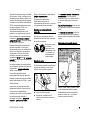 11
11
-
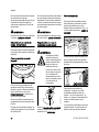 12
12
-
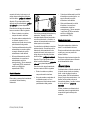 13
13
-
 14
14
-
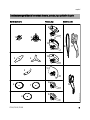 15
15
-
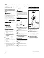 16
16
-
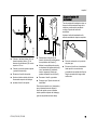 17
17
-
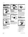 18
18
-
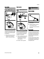 19
19
-
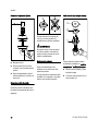 20
20
-
 21
21
-
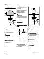 22
22
-
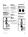 23
23
-
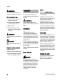 24
24
-
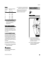 25
25
-
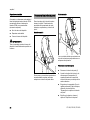 26
26
-
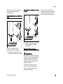 27
27
-
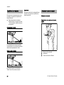 28
28
-
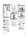 29
29
-
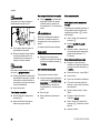 30
30
-
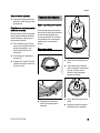 31
31
-
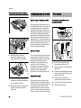 32
32
-
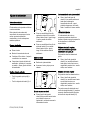 33
33
-
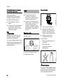 34
34
-
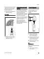 35
35
-
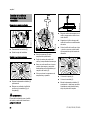 36
36
-
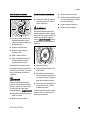 37
37
-
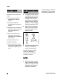 38
38
-
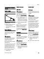 39
39
-
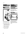 40
40
-
 41
41
-
 42
42
-
 43
43
-
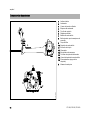 44
44
-
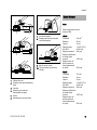 45
45
-
 46
46
-
 47
47
-
 48
48
-
 49
49
-
 50
50
-
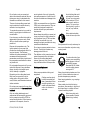 51
51
-
 52
52
-
 53
53
-
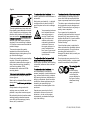 54
54
-
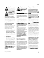 55
55
-
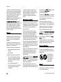 56
56
-
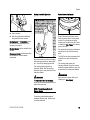 57
57
-
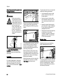 58
58
-
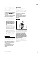 59
59
-
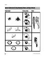 60
60
-
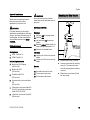 61
61
-
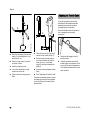 62
62
-
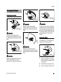 63
63
-
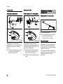 64
64
-
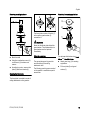 65
65
-
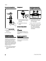 66
66
-
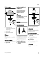 67
67
-
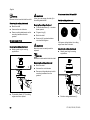 68
68
-
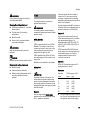 69
69
-
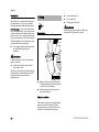 70
70
-
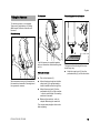 71
71
-
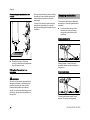 72
72
-
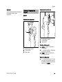 73
73
-
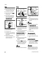 74
74
-
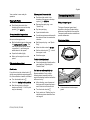 75
75
-
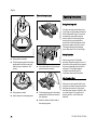 76
76
-
 77
77
-
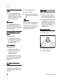 78
78
-
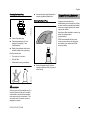 79
79
-
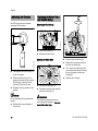 80
80
-
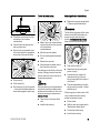 81
81
-
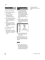 82
82
-
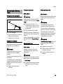 83
83
-
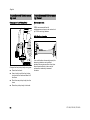 84
84
-
 85
85
-
 86
86
-
 87
87
-
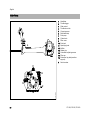 88
88
-
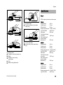 89
89
-
 90
90
-
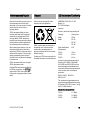 91
91
-
 92
92
-
 93
93
-
 94
94
-
 95
95
-
 96
96


STIHL FS 300, 350, 380 El manual del propietario
- Categoría
- Podadoras de césped
- Tipo
- El manual del propietario
en otros idiomas
Artículos relacionados
-
STIHL FR 460 TC Manual de usuario
-
-
-
-
-
-
-
-
-