Metra 108-FD5CH Instrucciones de operación
- Categoría
- Kits de coche
- Tipo
- Instrucciones de operación

The World’s best kits.
®
MetraOnline.com © COPYRIGHT 2019 METRA ELECTRONICS CORPORATION REV. 11/18/19 INST108-FD5CH
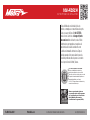
INSTALLATION INSTRUCTIONS
108-FD5CH
Attention! Let the vehicle sit with the key
out of the ignition for a few minutes before
removing the factory radio. When testing the
aftermarket equipment, ensure that all factory
equipment is connected before cycling the
key to ignition.
Patent Pending
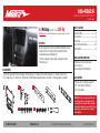
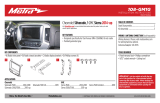
KIT FEATURES
• Designed specifically for the Pioneer DMH-C5500NEX 8-inch radio
• Included interface for climate and steering wheel functions
• Integrated passenger airbag indicator
• Touchscreen display for climate and personalization features
• Painted charcoal
KIT COMPONENTS
• A) Radio trim panel (with touchscreen display) • B) Radio brackets • C) Engine start/stop circuit board and cover
• D) Engine start/stop trim
• E) (6) Phillips screws
• F) (4) Panel clips • G) USB cable • H) HVAC interface and wiring harness (not shown) • I) Antenna adapter (not shown)
TOOLS REQUIRED
• Panel removal tool • Phillips screwdriver
• 9/32” socket wrench • Cutting tool
• Torx T-10 screwdriver
TABLE OF CONTENTS
Dash Disassembly ..............................................2-4
Kit Preparation ....................................................5-7
Kit Assembly ..........................................................8
Axxess Interface installation ............................9-17
Final Assembly ......................................................13
WIRING & ANTENNA CONNECTIONS
Wiring Harness: Axxess interface built
into touchscreen
Antenna Adapter: Included with kit
Ford Mustang (with 4.2” screen) 2015-Up
A B
E
C D
F G
Visit MetraOnline.com for more detailed information about the product and up-to-date vehicle
specific applications

1.800.221.0932
|
MetraOnline.com
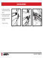
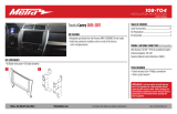
1. Open the passenger door and remove
the trim panel from the side of the dash.
(Figure A)
2. Open the glove box and remove the trim
panel on the right side. (Figure B)
3. Unclip and remove the trim/vent dash
panel. (Figure C)
Continued on the next page
(Figure B)(Figure A) (Figure C)
DASH DISASSEMBLY
2

REV. 11/18/2019 INST108-FD5CH
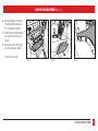
DASH DISASSEMBLY (CONT.)
3
(Figure F)
(Figure D) (Figure E)
4. Remove the rubber tray cover in front
of the shifter, and then remove the (2)
9/32” screws exposed. (Figure D)
5. Unclip and remove the front side panels
from each side of the center console.
(Figure E)
6. Remove the (2) 9/32” screws from each
side of the center console. (Figure F)
Continued on the next page

1.800.221.0932
|
MetraOnline.com
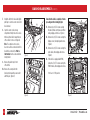
DASH DISASSEMBLY (CONT.)
(Figure I)
(Figure H) (Figure J)
(Figure G)
7. Unclip the shifter trim bezel and slightly
pull it up to clear the center console trim
bezel removal.
8. Open the center console storage
compartment. Unclip the center console
trim bezel, then slide it toward the rear
of the vehicle to remove it. (Figure G)
Note: The complete center console
does not need to be removed. but if it is
desired to be removed, the Push-to-
Start module must be connected when
testing the kit.
9. Remove the plastic tray in front
of the shifter.
10. Remove the center plastic trim
(knockout) between the power outlet
and USB jack. (Figure H)
Ensure that the vehicle is completely off before
proceeding onto the following (4) steps:
11. Remove the (4) 9/32” screws securing
the radio/climate control panel, and then
unclip, unplug, and remove. (Figure I)
12. Remove the (4) 9/32” screws securing the
display screen, then unplug and remove.
(Figure J)
13. Remove the (4) 9/32” screws securing the
radio chassis, then unplug and remove.
(Figure J)
14. If the vehicle is equipped with SYNC,
remove the (3) 9/32” screws securing the
SYNC® module, then unplug and remove.
Continue to Kit Preparation
4

REV. 11/18/2019 INST108-FD5CH
KIT PREPARATION
5
1. Cut and remove the shaded area from
the sub-dash to allow clearance for the
aftermarket radio. (Figure A)
Continued on the next page
Remove
shaded area
(Figure A)

1.800.221.0932
|
MetraOnline.com
6
3. Remove the rubber button membrane
from the back of the engine start/stop
switch panel. (Figure C)
4. Remove the engine start/stop switch
panel. (Figure D)
5. Press in on the (2) retaining tabs inside
the power outlet to remove the inner
portion, and then unsnap the outer ring
and cover. (Figure E)
Continued on the next page
From the factory radio/climate control panel:
1. Remove the (15) T-10 Torx screws securing
the plastic panel cover to the rear of the
panel, and then remove. (Figure A)
2. Remove the (7) T-10 Torx screws securing
the circuit board, and then remove.
(Figure B)
(Figure B)
(Figure A)
(Figure E)
(Figure C)
(Figure D)
KIT PREPARATION (CONT.)

REV. 11/18/2019 INST108-FD5CH
7
KIT PREPARATION
(CONT.)
To the 108-FD5B radio trim panel:
1. Attach the engine start/stop trim,
engine start/stop switch panel, and
then the rubber button membrane.
(Figure A)
2. Secure the engine start/stop circuit
board and cover to the switch/cover
assembly using (6) Phillips screws
provided. (Figure B)
3. Insert the USB cable into the USB slot,
through the rear. (Figure C)
4. Attach (4) panel clips provided.
(Figure D)
Continue to Kit Assembly
(Figure B) (Figure D)
(Figure A) (Figure C)

1.800.221.0932
|
MetraOnline.com
8
Note: For the following steps, reference
the installation manual provided with the
radio for which hardware to use. The display
screen and radio chassis use two different
types of screws.
1. Secure the radio brackets to the radio
chassis using (4) screws supplied with
the radio. (Figure A)
2. Secure the radio display to the radio
brackets using (4) screws supplied with
the radio. (Figure B)
Continue to Axxess
Interface Installation
(Figure A) (Figure B)
KIT ASSEMBLY

REV. 11/18/2019 INST108-FD5CH
AXXESS INTERFACE INSTALLATION
9
• Provides accessory power (12-volt 10-amp)
• Retains R.A.P. (retained accessory power)
• Provides NAV outputs (parking brake, reverse, speed sense)
• Retains audio controls on the steering wheel
• Retains the factory backup camera
• Retains balance and fade
• Micro-B USB updatable
INTERFACE FEATURES
• Crimping tool and connectors, or solder gun, solder, and heat shrink
• Tape • Wire cutter • Zip ties
TOOLS REQUIRED
• Axxess interface (built into the touchscreen display)
• Main harness
• HVAC interface
• HVAC interface harness
• 16-pin harness with stripped leads
• 12-pin backup camera harness
• 4-pin harness with yellow RCA jacks
Connections .............................................................................................................................10-11
Installation .................................................................................................................................. 12
Programming ...............................................................................................................................13
Touchscreen display operation ..............................................................................................14-15
Steering wheel control settings ............................................................................................16-17
Troubleshooting ...........................................................................................................................17
INTERFACE COMPONENTS
TABLE OF CONTENTS

1.800.221.0932
|
MetraOnline.com
10
From the main harness to the aftermarket radio:
• Connect the Black wire to the ground wire.
• Connect the Yellow wire to the battery wire.
• Connect the Blue wire to the system control (Blue/White) wire.
• Connect the Green wire to the left rear positive speaker output.
• Connect the Green/Black wire to the left rear negative speaker output.
• Connect the Purple wire to the right rear positive speaker output.
• Connect the Purple/Black wire to the right rear negative speaker output.
• Disregard the Red and White RCA jacks labeled “RSE/SYNC/SAT”, they will not be
used in this application.
• Disregard the Red and White RCA jacks labeled “FROM 3.5”, they will not be used
in this application.
Continued on the next page
From the 16-pin harness with stripped leads to the aftermarket radio:
• Connect the Red wire to the accessory wire.
• Connect the Orange/White wire to the illumination (lighting switch) wire
• Connect the Gray wire to the right front positive speaker output.
• Connect the Gray/Black wire to the right front negative speaker output.
• Connect the White wire to the left front positive speaker output.
• Connect the White/Black wire to the left front negative speaker output.
• Connect the Green/Purple wire to the reverse wire.
• Connect the Light Green wire to the parking brake wire.
• Tape off and disregard the following (7) wires, they will not be used in this application.
Blue/Pink, Blue/White, Brown, Green, Green/Black, Purple, Purple/Black
CONNECTIONS

REV. 11/18/2019 INST108-FD5CH
11
CONNECTIONS
(CONT.)
12-pin backup camera harness:
There are two different methods for connecting the factory backup camera.
If retaining the camera to the aftermarket radio is desired:
• Connect the Yellow RCA jack to the rear view camera input from the aftermarket radio.
If retaining the camera to the touchscreen display is desired:
• Connect the Yellow RCA jack, to the Yellow RCA jack from the 4-pin harness with yellow
RCA jacks labeled “Rearview camera”.
Note: If this method is chosen, the backup camera option must be enabled in the
Configuration Settings
.
•
Disregard the Yellow RCA jack from the 4-pin harness with yellow RCA jacks labeled “AUX video”,
it will not be used in this application
.
3.5mm jack - steering wheel control retention:
The 3.5mm jack is to be used to retain audio controls on the steering wheel control.
•
Connect the 3.5mm jack into the wired remote input from the aftermarket radio. Refer to
the manual provided with the radio if in doubt as to where the 3.5mm jack goes to.

1.800.221.0932
|
MetraOnline.com
12
INSTALL ATION
It is highly advisable to read the following steps beforehand, to ensure a clear understanding of
what is to be expected. The following steps must be done in the order that they are numbered.
With the vehicle completely off:
Touchscreen display
1. Connect the 16-pin harness with stripped leads into port “B” in the touchscreen display.
2. Connect the main harness to the wiring harnesses in the vehicle. These harnesses are the
ones removed in step 13 of dash disassembly. Then insert the main harness into port “A”
in the touchscreen display. But do not install this harness until exactly before step 1 of the
Programming section. This is a timed process.
3. Connect the 4-pin harness with yellow RCA jacks into port “C” in the touchscreen display.
4. Disregard ports “D” and “E”, they will not be used in this application.
5. Port “F” is an update port for future firmware upgrades.
A
B
C
E
F
D
HVAC interface
6. Connect the HVAC interface harness into the HVAC interface, and then to the wiring
harnesses in the vehicle. These harnesses are the ones removed in step 11
of dash disassembly.
a. Then connect the 10-pin harness into the engine start/stop circuit board assembly.
Attention! There are (2) 10-pin connectors, one in the engine start/stop circuit board assembly,
and one in the touchscreen display. Use only the appropriate connector and disregard the other
one. If the incorrect port is accidentally used, the vehicle will need to be reset by removing the
battery for a couple minutes.
Note: Disregard the 4-pin flat to 4-pin stacked harness, it will not be used in this application
.
7. Connect the 6-pin harness from the main harness to the HVAC interface.
8. Connect the 12-pin backup camera harness, to the wiring harness in the vehicle. This
harness is the one removed in step 12 of dash disassembly.
9. Locate the factory antenna connector in the dash and complete all necessary connections to
the radio. Use the antenna adapter provided to adapt the factory antenna connector to the
aftermarket radio.
Continued on the next page
Note: DO NOT CONNECT!

REV. 11/18/2019 INST108-FD5CH
13
PROGRAMMING FINAL ASSEMBLY
1. Connect the USB cable attached to the radio trim panel, to the USB port in the back
of the radio.
2. Secure the completed radio assembly into the upper dash using the factory hardware
removed in step 12 of dash disassembly.
3. Snap the
radio trim panel
over the completed radio assembly, then reassemble the
dash in reverse order of disassembly.
1. Refer to step 2 from the Installation section.
2. Press the push-to-start button to start the vehicle.
Note: If the Push-to-Start module in the center console has been disconnected, reconnect it.
3. Program the kit:
a. Once the touchscreen display loads up, select the vehicle type.
b. Wait until the radio comes on, and the touchscreen display shows SWC Configured*.
This process may take up to 3 minutes.
Note: If the touchscreen display doesn’t load up, or the radio doesn’t come on within
3 minutes, and/or the touchscreen display doesn’t show SWC Configured*, check all
connections, then reset the interface and try again. Refer to the Troubleshooting section.
* For models with steering wheel controls.
4.
Cycle the key off. If the driver’s door is closed, open and close the door. Cycle the key back on.
5. Test all functions of the installation for proper operation, before reassembling the dash.

1.800.221.0932
|
MetraOnline.com
14
• This is the climate control screen which will be displayed on the touchscreen display.
This is considered the Main Menu.
• Disregard the upper left tab with (3) arrows, it will not be used in this application.
• The upper right tab with the gear icon will take you to the Configuration Settings screen.
• The climate controls will function in the same manner that they did with the factory
climate controls, yet via touchscreen buttons instead. The temperature control will display a
numerical scale, with LO being the coldest, and HI being the hottest: LO / 1-9 / HI
Continued on the next page
Climate Control screen
TOUCHSCREEN DISPLAY OPERATION

REV. 11/18/2019 INST108-FD5CH
15
TOUCHSCREEN DISPLAY OPERATION
(CONT.)
• Backlight
• For controlling the color of the buttons and back-light intensity.
• Backup Camera
•
Enable/disables the backup camera image to the touchscreen display. Disabled by default
.
• Forward Camera (disregard for this application)
• Ambient Lighting Color
• For adjusting the ambient light color in the vehicle
• Steering Wheel Controls
• Remap Buttons – For remapping the steering wheel control buttons
• Dual Assign – For dual assigning the steering wheel control buttons (long button press)
• Select Radio – For auto detecting the radio, or changing the radio type
• Clock
• For setting the clock and hour mode
• System Configuration
• About - Information regarding the software in the kit
• Temperature Unit - To change between Celsius and Fahrenheit
• Digital Amp Gain - For adjusting the output gain to the amplifier
• Reset Vehicle Type - To reset the kit to default settings
Configuration Settings

1.800.221.0932
|
MetraOnline.com
16
STEERING WHEEL CONTROL SETTINGS
Remap Buttons Dual Assign
• The interface has the ability to change the button assignment for the steering wheel
control audio buttons, except Volume-Up and Volume-Down. Follow the prompts on the
touchscreen display to remap the steering wheel control audio button(s) to your liking.
Note: The aftermarket radio may not have all of these commands. Please refer to the
manual provided with the radio, or contact the radio manufacturer, for specific commands
recognized by that particular radio.
• The interface has the capability to assign two functions to a single button, except
Volume-Up and Volume-Down. Follow the prompts on the touchscreen display to program
the button(s) to your liking.
Note: Seek-Up and Seek-Down come programmed as Preset-Up and Preset-Down
for a long button press.
Continued on the next page

REV. 11/18/2019 INST108-FD5CH
17
STEERING WHEEL CONTROL SETTINGS
(CONT.)
Select Radio
* Note: If the interface shows an Alpine radio, that means the interface doesn’t detect a radio
connected it, i.e., an open connection. Verify that the 3.5mm jack is connected to the correct
steering wheel jack in the radio.
• To show which brand radio is “auto detected” to the interface, press the Autodetect button.
The radio detected will have a filled in circle. If the incorrect radio is shown, select Pioneer.
Resetting the interface
1. With the vehicle running, press the Reset Vehicle Type button mentioned in
System Configuration.
2. Refer to Programming, step 3, from this point.
TROUBLESHOOTING


REV. 11/18/2019 INST108-FD5CH
19

The World’s best kits.
®
MetraOnline.com © COPYRIGHT 2019 METRA ELECTRONICS CORPORATION REV. 11/18/19 INST108-FD5CH
INSTALLATION INSTRUCTIONS
108-FD5CH
KNOWLEDGE IS POWER
Enhance your installation and fabrication skills by
enrolling in the most recognized and respected
mobile electronics school in our industry.
Log onto www.installerinstitute.com or call
800-354-6782 for more information and take steps
toward a better tomorrow.
®
Metra recommends MECP
certified technicians
If you are having difficulties with the installation
of this product, contact our Tech Support line
either by phone at 386-257-1187, or email at
techsupport@metra-autosound.com. Before
doing so, look over the instruction booklet a
second time and ensure that the installation was
performed exactly as the instruction booklet
is stated. Have the vehicle apart and ready to
perform troubleshooting steps before contacting
Metra/Axxess Tech Support.

The World’s best kits.
®
MetraOnline.com © COPYRIGHT 2019 METRA ELECTRONICS CORPORATION REV. 11/18/19 INST108-FD5CH
INSTRUCCIONES DE INSTALACIÓN
108-FD5CH
¡Precaución!
Todos los accesorios, interruptores,
paneles de controles de clima y especialmente las
luces del indicador de las bolsas de aire deben estar
conectados antes ciclar la ignición. Además, no quite
el radio de fábrica con la llave en la posición o de
encendido ni con el vehículo funcionando.
Patente pendiente
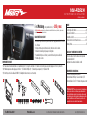
COMPONENTES DEL KIT
• A) Panel de la moldura del radio (con pantalla táctil) • B) Soportes del radio • C) Tablero de circuitos para encender/apagar el motor y cubierta
• D) Moldura para encender/apagar el motor • E) Tornillos Phillips (6) • F) Ganchos para panel (4) • G) Cable USB
• H) Interfaz y arnés de cableado HVAC • I) Adaptador de antena (no se muestra)
HERRAMIENTAS REQUERIDAS
• Herramienta para quitar paneles
• Destornillador Phillips • Llave del tubo 9/32”
• Destornillador Torx T-10 • Herramienta para cortar
INDICE
Desmontaje del tablero .................................... 2-4
Preparación del kit ..............................................5-7
Ensamble del kit ....................................................8
Instalación de la interfase Axxess ...................9-17
Montaje final .........................................................13
CABLEADO Y CONEXIONES DE ANTENA
Arnés de cables: Interfaz Axxess incorporada
en pantalla táctil
Adaptador de antena: Incluido con kit
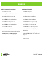
CARACTERÍSTICAS DEL KIT
• Diseñado específicamente para la radio de 8 pulgadas DMH-C5500NEX
de Pioneer
• Incluye interfaz para climatización y funciones del volante.
• Indicador de airbag del pasajero integrado
• Pantalla táctil para el clima y características de personalización
• Pintura gris oscuro
Ford Mustang (con pantalla de 4,2 “) 2015 y mas
Visite MetraOnline.com para obtener información más detallada sobre el producto y aplicaciones
actualizadas específicas para vehículos.
A B
E
C D
F G

1.800.221.0932
|
MetraOnline.com
DESMONTAJE DEL TABLERO
2
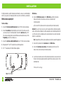
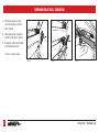
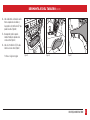
1. Abra la puerta del pasajero y quite
el panel de la moldura en el lado del
tablero. (Figura A)
2. Abra la guantera y quite el panel de la
moldura en el lado derecho. (Figura B)
3. Desenganche y quite el panel del tablero
de la moldura/rejilla. (Figura C)
Continua en la siguiente pagina
(Figura B)(Figura A) (Figura C)

REV. 11/18/2019 INST108-FD5CH
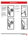
DESMONTAJE DEL TABLERO (CONT.)
3
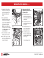
(Figura F)
(Figura D) (Figura E)
4. Quite la cubierta de la charola de caucho
frente a la palanca de velocidades y
luego quite los (2) tornillos de 9/32” que
quedan a la vista. (Figura D)
5. Desenganche y quite los paneles
laterales frontales de cada lado de la
consola central. (Figura E)
6. Quite los (2) tornillos de 9/32” de cada
lado de la consola central. (Figura F)
Continua en la siguiente pagina

1.800.221.0932
|
MetraOnline.com
4
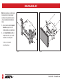
DESMONTAJE DEL TABLERO
(CONT.)
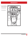
(Figura I)
(Figura H) (Figura J)
(Figura G)
7. Desenganche el bisel de la moldura
de la palanca de velocidades y jálela
ligeramente hacia arriba para poder
quitar la bisel central de la consola
central.
8. Abra el compartimiento de
almacenamiento de la consola central.
Suelte el bisel de la consola central,
luego deslícelo hacia la parte trasera del
vehículo para retirarlo. (Figura G)
Nota: No es necesario quitar la consola
central completa. pero si se desea quitar,
el módulo Push-to-Start debe estar
conectado al probar el kit.
9. Quite la charola de plástico de la parte
frontal de la palanca de velocidades.
10. Quite la moldura de plástico del centro
(panel) entre la salida de alimentación y
el conector USB. (Figura H)
Asegúrese de que el vehículo esté
completamente apagado antes de pasar a
los siguientes (3) pasos:
11. Quite los (4) tornillos de 9/32” que
sujetan el panel del radio/control del
clima, y luego desenganche, desconecte
y quite. (Figura I)
12. Quite los (4) tornillos de 9/32” que
sujetan la pantalla, luego desconecte y
quite. (Figura J)
13. Quite los (4) tornillos de 9/32” que
sujetan el chasis del radio, luego
desconecte y quite. (Figura J)
14. Si el vehículo está equipado con
SYNC, quite los (3) tornillos de 9/32”
que sujetan el módulo SYNC®, luego
desconecte y quite.
Continuar la Preparación del Kit

REV. 11/18/2019 INST108-FD5CH
5
PREPARACIÓN DEL KIT
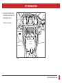
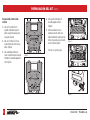
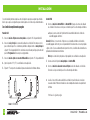
1. Corte y quite el área sombreada del sub
tablero para hacer espacio para el radio
de mercado secundario. (Figura A)
Continua en la siguiente pagina
Quite el área
sombreada
(Figura A)

1.800.221.0932
|
MetraOnline.com
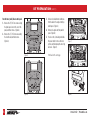
4. Quite el panel del interruptor de
encendido/apagado del motor.
(Figura D)
5. Oprima hacia adentro en las (2)
pestañas de retención dentro de la
salida de alimentación y quite la porción
interna, y luego suelte a presión el anillo
exterior y cubierta. (Figura E)
Continua en la siguiente pagina
Del panel del radio/control del clima
de fábrica:
1. Quite los (15) tornillos Torx T-10
sujetando la cubierta del panel de
plástico a la parte trasera del panel y
luego quite. (Figura A)
2. Quite los (7) tornillos Torx T-10 que
sujetan el tablero de circuitos y luego
quítelo. (Figura B)
3. Quite la membrana del botón de
caucho de la parte trasera del panel del
interruptor de encendido/apagado del
motor. (Figura C)
(Figura B)
(Figura A)
(Figura E)
(Figura C)
(Figura D)
6
PREPARACIÓN DEL KIT
(CONT.)

REV. 11/18/2019 INST108-FD5CH
PREPARACIÓN DEL KIT (CONT.)
7
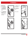
Al panel de la moldura del radio 108-FD5CH:
1. Una la moldura de encendido/apagado
del motor, panel del interruptor de
encendido/apagado del motor y luego
la membrana del motor de caucho.
(Figura A)
2. Sujete el tablero de circuitos de
encendido/apagado del motor y
cubierta al ensamble del interruptor/
cubierta usando los (6) tornillos Phillips
(Figura B)
3. Inserte el cable USB en la ranura USB,
por la parte trasera. (Figura C)
4. Conecte los (4) ganchos para panel
suministrados. (Figura D)
Continúe con el Ensamble del Kit
(Figura B) (Figura D)
(Figura A) (Figura C)

1.800.221.0932
|
MetraOnline.com
ENSAMBLE DEL KIT
8
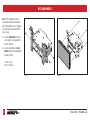
Nota: Para los siguientes pasos, consulte el manual
de instalación provisto con la radio para saber
qué hardware usar. La pantalla de visualización y
el chasis de radio utilizan dos tipos diferentes de
tornillos.
1.
Deslice el chasis de la radio entre los soportes
de la radio, luego asegúrelo con los (4)
tornillos suministrados con la radio. (Figura A)
2.
Sujete los soportes de radio a la pantalla de
visualización de la radio con los (6) tornillos
suministrados con la radio. (Figura B)
Continúe con la instalación
de la Interfaz Axxess
(Figura A) (Figura B)

REV. 11/18/2019 INST108-FD5CH
INSTALACIÓN DE LA INTERFASE AXXESS
• Provee corriente de accesorio (12 voltios 10 amperes)
• Retiene R.A.P. (corriente de accesorio retenida)
• Proporciona salidas de NAV (freno de mano, reversa, sensor de velocidad)
• Retiene los controles de audio en el volante
• Retiene la cámara de reversa de fábrica
• Retiene el balance y la intensidad
• Actualizable por micro-B USB
INSTALACIÓN DE LA INTERFAZ AXXESS
• Herramienta de ponchadora y conectores, o pistola de soldadura, soldadura y termocontracción
• Cinta • Cortacables • Zip lazos
HERRAMIENTAS REQUERIDAS
• Interfaz Axxess (integrada a la pantalla táctil)
• Arnés principal
• Interfaz HVAC
• Arnés de la interfaz HVAC
• Arnés de 16 pins con conectores pelados
• Arnés de cámara de reversa de 12 pins
• Arnés de 4 pins con conectores RCA amarillos
Conexiones ..............................................................................................................................10-12
Instalación ................................................................................................................................... 12
Programación ...............................................................................................................................13
Operación de la pantalla táctil ...............................................................................................14-15
Configuración del control en el volante ................................................................................16-17
Resolución de problemas ............................................................................................................17
COMPONENTES DE LA INTERFAZ
INDICE
9

1.800.221.0932
|
MetraOnline.com
CONEXIONES
10
Desde el arnés principal al radio de mercado secundario:
• Conecte el cable negro al cable de tierra.
• Conecte el cable amarillo al cable de la batería.
• Conecte el cable azul al cable control del sistema (azul / blanco)
• Conecte el cable verde con la salida positiva de la bocina izquierda trasera.
• Conecte el cable verde/negro con la salida negativa de la bocina izquierda trasera.
• Conecte el cable púrpura con la salida positiva de la bocina derecha trasera.
• Conecte el cable púrpura/negro con la salida negativa de la bocina derecha trasera.
• No tenga en cuenta las tomas RCA rojas y blancas con la etiqueta “RSE / SYNC / SAT”,
no serán utilizado en esta aplicación.
• Ignore los conectores RCA rojo y blanco rotulados “FROM 3.5”; no se utilizarán en esta
aplicación.
Continua en la siguiente pagina
Del arnés de 16 pins con conectores pelados al radio de mercado secundario:
• Conecte el cable rojo al cable de accesorios.
• Conecte el cable anaranjado/blanco al cable de iluminación (interruptor de iluminación).
• Conecte el cable gris con la salida positiva de la bocina derecha delantera.
• Conecte el cable gris/negro con la salida negativa de la bocina derecha delantera.
• Conecte el cable blanco con la salida positiva de la bocina izquierda delantera.
• Conecte el cable blanco/negro con la salida negativa de la bocina izquierda delantera.
• Conecte el cable verde/púrpura al cable de reversa.
• Conecte el cable verde claro al cable de freno de mano.
• Coloque cinta e ignore los siguientes (7) cables; no se utilizarán en esta aplicación.
azul/rosa, azul/blanco, marrón, verde, verde/negro, púrpura, púrpura/negro

REV. 11/18/2019 INST108-FD5CH
CONEXIONES (CONT.)
11
La retención del control en volante con conector de 3.5 mm
El conector de 3.5 mm se debe usar para retener los controles de audio en el control del volante.
• Conecte el conector de 3.5 mm a la entrada remota con cable del radio de mercado secundario.
Consulte el manual provisto con la radio si tiene dudas sobre a dónde va el conector de 3.5 mm.
Arnés de cámara de reversa de 12 pins:
Existen dos métodos distintos para conectar la cámara de reversa de fábrica.
Si se desea retener la cámara al radio de mercado secundario:
• Conecte el conector amarillo RCA a la entrada de la cámara de visión trasera desde la radio del
mercado de accesorios.
Si se desea retener la cámara a la pantalla táctil:
• Conecte el conector RCA amarillo al conector RCA amarillo del arnés de 4 pins con conectores
RCA amarillos rotulados “Rearview camera”.
Nota: Si se elige este método, la opción de cámara de reversa debe estar habilitada en la
Pantalla de configuración.
• No tenga en cuenta el conector RCA amarillo del arnés de 4 pines con los conectores RCA
amarillos con la etiqueta “AUX video”, no se utilizará en esta aplicación.

1.800.221.0932
|
MetraOnline.com
INSTAL ACIÓN
12
Se recomienda de gran manera que lea antes los siguientes pasos para asegurar que entienda
bien lo que se espera. Los siguientes pasos deben seguirse en el orden en que están numerados.
Con el vehículo completamente apagado:
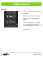
Pantalla táctil
1. Conecte el arnés de 16 pins con conectores pelados en el puerto “B” en la pantalla táctil.
2. Conecte el
arnés principal
a los arneses del cableado en el vehículo. Estos arneses son los
que se retiran del paso 13 en el desmontaje del tablero. Después inserte el arnés principal en
el puerto “A” en la pantalla táctil. Pero no instale este arnés hasta que llegue justo antes del
paso 1 de Programación. Este es un proceso programado.
3. Conecte el arnés de 4 pins con conectores RCA amarillos en el puerto “C” en la pantalla táctil.
4. Ignore los puertos “D” y “E”; no se utilizarán en esta aplicación.
5. El puerto “F” es un puerto de actualización para actualizaciones de firmware futuras.
A
B
C
E
F
D
Interfaz HVAC
6. Conecte el arnés de la interfaz HVAC en la interfaz HVAC y luego a los arneses de cableado
en el vehículo. Estos arneses son los que se retiran del paso 11 en el desmontaje del tablero.
a. Después conecte el arnés de 10 pins dentro del ensamble del tablero de circuitos de
encendido/apagado del motor.
¡Atención! Existen (2) conectores de 10 pins; uno en el ensamble del tablero de circuito de
encendido/apagado del motor, y uno en la pantalla táctil. Use únicamente el conecto apropiado
e ignore el otro. Si se usa accidentalmente el puerto incorrecto, el vehículo deberá restablecerse
quitando la batería durante unos minutos.
Nota: Ignore el arnés de 4 pins planos a 4 pins apilados; no se utilizará en esta aplicación.
7. Conecte el arnés de 6 pins del arnés principal en la interfaz HVAC.
8. Conecte el arnés de la cámara de reversa de 12 pins al arnés del cableado en el vehículo.
Este arnés es el que se retira del paso 12 en el desmontaje del tablero.
9. Localice el conector de la antena de fábrica en el tablero y realice todas las conexiones
necesarias al radio. Metra recomienda el uso de un adaptador adecuado de acoplamiento
de Metra.
Continua en la siguiente pagina
Nota: NO SE CONECTA!

REV. 11/18/2019 INST108-FD5CH
PROGRAMACIÓN ENSAMBLE FINAL
13
1. Conecte el cable USB unido al panel de la moldura del radio al puerto USB en la parte
trasera del radio, en su caso.
2. Sujete el montaje de radio terminado en el tablero superior con la herramienta de fábrica
que quitó en el paso 12 del desmontaje del tablero.
3. Coloque a presión el panel de la moldura del radio sobre el montaje de radio completo y
luego vuelva a armar el tablero al revés de cómo lo desarmó.
1. Haga referencia al paso 2 de Instalación.
2. Oprima el botón para encender el vehículo.
Nota: si se ha desconectado el módulo Push-to-Start en la consola central, vuelva a
conectarlo.
3. Programar el kit:
a. Una vez que la pantalla táctil se carga, seleccione el tipo de vehículo.
b. Espere a que se encienda el radio y la pantalla táctil muestre SWC Configured*.
Este proceso puede requerir hasta 3 minutos.
Nota: Si la pantalla táctil no se carga o el radio no se enciendo en los siguientes 3 minutos,
y/o la pantalla táctil no muestra SWC Configured*. Verifique todas las conexiones, luego
reinicie la interfaz e intente nuevamente. Consulte la sección Resolución de problemas.
* Para modelos con mandos en el volante.
4. Apague la llave y vuelva a encenderla. Si la puerta del conductor está cerrada, abra y cierre
la puerta.
5. Pruebe todas las funciones de la instalación para verificar la operación correcta antes de
volver a ensamblar el tablero.

1.800.221.0932
|
MetraOnline.com
14
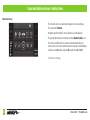
OPERACIÓN DE LA PANTALLA TÁCTIL
• Esta es la pantalla de control HVAC que se mostrará en la pantalla táctil. Esto se considera
como la pantalla principal.
• Ignore la pestaña superior izquierda con (3) flechas; no se utilizará en esta aplicación.
• La etiqueta superior derecha con el ícono de engrane lo llevará a la pantalla de
Configuraciones.
• Los controles del clima funcionarán del mismo modo que con los controles del clima de
fábrica, solo que con botones en la pantalla táctil. El control de temperatura mostrará una
escala numérica, siendo LO en más frío y HI el más caliente: LO / 1-9 / HI
Continua en la siguiente pagina
Pantalla de control HVAC

REV. 11/18/2019 INST108-FD5CH
15
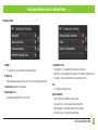
OPERACIÓN DE LA PANTALLA TÁCTIL
(CONT.)
• Controles en el volante
• Botones de reubicación: para reubicar los botones del control en el volante
• Doble asignación: para doble asignación de los botones de control en el volante
(presionar el botón por largo tiempo)
• Seleccionar radio: para detectar automáticamente el radio o cambiar el tipo de radio
• Reloj
• Para configurar el modo reloj y hora.
• Configuración del sistema
• Acerca de - Información sobre el software en el kit
• Unidad de temperatura - Para cambiar entre Celsius y Fahrenheit
• Ganancia de amplificación digital - Para ajustar la ganancia de salida al amplificador
•
Restablecer el tipo de vehículo - Para restablecer el kit a la configuración predeterminada
Pantalla de Configuraciones
• Luz posterior
• Para controlar el color de los botones y la intensidad de la luz posterior.
• Cámara de reversa
•
Activa / desactiva la imagen de la cámara de respaldo en la pantalla táctil.
Deshabilitado por defecto.
• Cámara delantera
(ignorar esta aplicación)
• Color de iluminación ambiental
• Para ajustar el color de la luz ambiental en el vehículo.

1.800.221.0932
|
MetraOnline.com
16
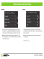
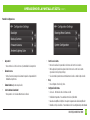
CONFIGURACIÓN DEL CONTROL EN EL VOLANTE
Pantalla para reubicar el botón Pantalla de doble asignación
• La interfaz tiene la capacidad de cambiar la asignación de botón para los botones de audio del
control en el volante, excepto para Subir volumen y Bajar volumen. Siga las indicaciones en la
pantalla táctil para reubicar el(los) botón(es) de audio del control en el volante a su gusto.
Nota: El radio de mercado secundario puede no tener todos estos comandos. Consulte el
manual del suministrado con el radio o comuníquese con el fabricante del radio para obtener
los comandos específicos reconocidos por ese radio en particular.
• La interfaz tiene la capacidad de asignar dos funciones a un solo botón, excepto Subir
volumen y Bajar volumen. Siga las indicaciones en la pantalla táctil para programar el(los)
botón(es) a su gusto.
Nota: Buscar anterior y Buscar siguiente vienen programados como Subir preestablecido y
Bajar preestablecido cuando se presiona el botón por largo tiempo.
Continua en la siguiente pagina

REV. 11/18/2019 INST108-FD5CH
17
CONFIGURACIÓN DE CONTROL EN VOLANTE
(CONT.)
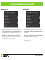
Seleccionar la pantalla del radio
• Para mostrar qué marca de radio se “detecta automáticamente” a la interfaz, oprima el
botón Autodetect. El radio detectado tendrá un círculo rellenado. Si se muestra el radio
incorrecto, seleccione Pioneer.
* Nota:
Si la interfaz muestra un radio Alpine, eso significa que la interfaz no detecta un
radio conectado a él; es decir, una conexión abierta. Verifique que el conector de 3.5 mm esté
conectado al conector correcto del volante en el radio.
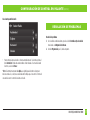
Resolución de problemas
1. Con el vehículo en funcionamiento, presione el botón Restablecer tipo de vehículo
mencionado en Configuración del sistema.
2. Consulte Programación, paso 3, desde este punto.
RESOLUCIÓN DE PROBLEMAS


REV. 11/18/2019 INST108-FD5CH
19

The World’s best kits.
®
MetraOnline.com © COPYRIGHT 2019 METRA ELECTRONICS CORPORATION REV. 11/18/19 INST108-FD5CH
INSTRUCCIONES DE INSTALACIÓN
108-FD5CH
KNOWLEDGE IS POWER
Enhance your installation and fabrication skills by
enrolling in the most recognized and respected
mobile electronics school in our industry.
Log onto www.installerinstitute.com or call
800-354-6782 for more information and take steps
toward a better tomorrow.
®
Metra recomienda técnicos
con certificación del Programa
de Certificación en Electrónica
Móvil (Mobile Electronics
Certification Program, MECP).
EL CONOCIMIENTO ES PODER
Mejore sus habilidades de instalación y
fabricación inscribiéndose en la escuela de
dispositivos electrónicos móviles más reconocida
y respetada de nuestra industria. Regístrese en
www.installerinstitute.com o llame al
800-354-6782 para obtener más información y
avance hacia un futuro mejor.
Si tiene dificultades con la instalación de este
producto, comuníquese con nuestra línea de soporte
técnico, ya sea por teléfono al 1-800-253-TECH, o
envíe un correo electrónico a techsupport@metra-
autosound.com. Antes de hacerlo, revise el folleto
de instrucciones por segunda vez y asegúrese de
que la instalación se realizó exactamente como
se indica en el manual de instrucciones. Tenga el
vehículo separado y listo para realizar los pasos de
solución de problemas antes de ponerse en contacto
con el soporte técnico de Metra / Axxess.
-
 1
1
-
 2
2
-
 3
3
-
 4
4
-
 5
5
-
 6
6
-
 7
7
-
 8
8
-
 9
9
-
 10
10
-
 11
11
-
 12
12
-
 13
13
-
 14
14
-
 15
15
-
 16
16
-
 17
17
-
 18
18
-
 19
19
-
 20
20
-
 21
21
-
 22
22
-
 23
23
-
 24
24
-
 25
25
-
 26
26
-
 27
27
-
 28
28
-
 29
29
-
 30
30
-
 31
31
-
 32
32
-
 33
33
-
 34
34
-
 35
35
-
 36
36
-
 37
37
-
 38
38
-
 39
39
-
 40
40


Metra 108-FD5CH Instrucciones de operación
- Categoría
- Kits de coche
- Tipo
- Instrucciones de operación
En otros idiomas
Documentos relacionados
-
Metra 108-FD4CH Instrucciones de operación
-
Metra 95-6553B Instrucciones de operación
-
Metra 108-TO2CHG Instrucciones de operación
-
Metra Electronics 108-FD3B Instrucciones de operación
-
 Metra Electronics 108-GM1G Instrucciones de operación
-
 Metra Electronics 108-TO4 Instrucciones de operación
-
-
-


