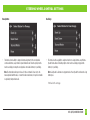
Metra 108-FD4CH Instrucciones de operación
- Tipo
- Instrucciones de operación
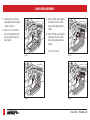
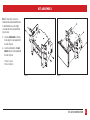
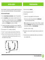
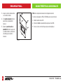
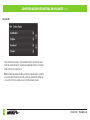
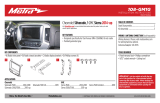
El Metra 108-FD4CH te permite instalar una radio Pioneer DMH-C5500NEX de 8 pulgadas en tu Ford Mustang del 2010 al 2014. Incluye una interfaz para las funciones del volante y del climatizador, una pantalla táctil para controlar el clima, el audio y funciones de personalización, y está pintado de color carbón para que coincida con el acabado de fábrica. También conserva SYNC y la entrada AUX-IN de fábrica.
El Metra 108-FD4CH te permite instalar una radio Pioneer DMH-C5500NEX de 8 pulgadas en tu Ford Mustang del 2010 al 2014. Incluye una interfaz para las funciones del volante y del climatizador, una pantalla táctil para controlar el clima, el audio y funciones de personalización, y está pintado de color carbón para que coincida con el acabado de fábrica. También conserva SYNC y la entrada AUX-IN de fábrica.


-
 1
1
-
 2
2
-
 3
3
-
 4
4
-
 5
5
-
 6
6
-
 7
7
-
 8
8
-
 9
9
-
 10
10
-
 11
11
-
 12
12
-
 13
13
-
 14
14
-
 15
15
-
 16
16
-
 17
17
-
 18
18
-
 19
19
-
 20
20
-
 21
21
-
 22
22
-
 23
23
-
 24
24
-
 25
25
-
 26
26
-
 27
27
-
 28
28
-
 29
29
-
 30
30
-
 31
31
-
 32
32


Metra 108-FD4CH Instrucciones de operación
- Tipo
- Instrucciones de operación
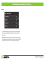
El Metra 108-FD4CH te permite instalar una radio Pioneer DMH-C5500NEX de 8 pulgadas en tu Ford Mustang del 2010 al 2014. Incluye una interfaz para las funciones del volante y del climatizador, una pantalla táctil para controlar el clima, el audio y funciones de personalización, y está pintado de color carbón para que coincida con el acabado de fábrica. También conserva SYNC y la entrada AUX-IN de fábrica.
en otros idiomas
Artículos relacionados
-
Metra 108-FD6CH Instrucciones de operación
-
-
Metra 95-6553B Instrucciones de operación
-
-
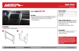 Metra Electronics 108-TO4 Instrucciones de operación
-
Metra Electronics 108-FD3B Instrucciones de operación
-
 Metra Electronics 108-GM1G Instrucciones de operación
-
-


