Axxess AXPIO-JL1 Manual de usuario

Tipo
Manual de usuario

El Axxess AXPIO-JL1 es un dispositivo que permite la instalación de un radio Pioneer DMH-W4600NEX/WC4660NEX en un Jeep Wrangler JL del 2018 en adelante, manteniendo las funciones originales del vehículo como los controles de audio en el volante, la cámara de reversa y la pantalla de información del conductor. También permite la integración de una cámara frontal y un micrófono externo para llamadas telefónicas.

El Axxess AXPIO-JL1 es un dispositivo que permite la instalación de un radio Pioneer DMH-W4600NEX/WC4660NEX en un Jeep Wrangler JL del 2018 en adelante, manteniendo las funciones originales del vehículo como los controles de audio en el volante, la cámara de reversa y la pantalla de información del conductor. También permite la integración de una cámara frontal y un micrófono externo para llamadas telefónicas.

AXPIO-JL1
INSTALLATION INSTRUCTIONS
AxxessInterfaces.com © COPYRIGHT 2022 METRA ELECTRONICS CORPORATION REV. 10/14/22 INSTAXPIO-JL1
TOOLS & INSTALLATION ACCESSORIES REQUIRED
• Panel removal tool • Phillips screwdriver
• Torx screwdrivers
TABLE OF CONTENTS
Dash Disassembly ..................................................2
Kit Assembly
- Radio Provision ...................................................2
- Pioneer Modular DDIN Radio Provision .............3
Axxess Interface Installation ............................4-16
Jeep Wrangler
JL
2018-Up
Note:
This kit will function in both Single-Zone and Dual-Zone vehicles:
• All HVAC functions will be retained.
• Single-Zone vehicles will only get status feedback of the HVAC functions,
while Dual-Zone vehicles can also be controlled through the radio screen.
• Compass is only retained on vehicles equipped with the UConnect 3
(5" touchscreen).
• The External Speaker is only required in vehicles with safety group features.
Attention! Designed specifically for Pioneer’s DMH-W4600NEX/WC4660NEX.
Pioneer 9" DMH-WC6600NEX will require the Metra Floating Mount Kit
109-UN02. (sold separately)
KIT COMPONENTS
A) Radio bezel • B) Shallow mount brackets (2) • C) Modular radio brackets (2) • D) Panel clips (4)
A B C D
WIRING & ANTENNA CONNECTIONS
Wiring Harness: Included with Kit
Antenna Adapter: Included with Kit
GPS Antenna Adapter: Included with Kit
Visit AxxessInterfaces.com for up-to-date
vehicle specific applications.
Product Info
2
DASH DISASSEMBLY KIT ASSEMBLY
1. Unsnap and remove the panel below the
steering column. (Figure A)
2. Using the panel removal tool, carefully
unclip the climate control panel, unplug
the HVAC and start/stop button, and
then set aside. (Figure B)
3. Remove (2) Phillips screws securing the
radio trim panel, then, starting at the
bottom, unclip and remove the panel.
(Figure C)
4. Remove (4) Phillips screws securing the
factory radio, disconnect the wiring, and
then remove the radio.
(Figure A)
(Figure B)
(Figure C)
(Figure A)
(Figure B)
Radio provision
1. Secure the
shallow radio brackets
to
the radio using screws supplied with the
radio. (Figure A)
2. Locate the factory wiring harness and
antenna connector in the dash and
complete all necessary connections to
the radio. Metra recommends using the
proper mating adapter from Metra and/
or Axxess.
3. Reconnect the negative battery terminal
and test the Pioneer radio for proper
operation.
4. Place the radio into the dash, then
secure using the factory screws.
5. Attach (4)
panel clips
provided with this
kit onto the
radio bezel
, and then snap
the bezel over the radio. (Figure B)
6. Reassemble the dash in the reverse
order of disassembly to complete
the installation.
3
REV. 10/14/22 INSTAXPIO-JL1
KIT ASSEMBLY
(Figure C)
(Figure A)
(Figure B)
Pioneer Modular DDIN radio provision
1. Secure the radio display to the
modular
radio brackets
using (6) screws supplied
with the radio. (Figure A)
Note: Reference the aftermarket radio’s
installation manual to determine which
screws secure the radio display.
2. Secure the radio chassis to the radio
display/bracket assembly using (4)
screws supplied with the radio. (Figure B)
Note: Reference the aftermarket radio’s
installation manual to determine which
screws secure the radio chassis.
3. Route the RGB extension cable from the
radio chassis to the display screen, then
connect the cable to the display screen.
4. Locate the factory wiring harness and
antenna connector in the dash and
complete all necessary connections to
the radio. Metra recommends using
the proper mating adapter from Metra
and/or Axxess.
5.
Reconnect the negative battery
terminal and test the Pioneer radio for
proper operation.
6. Place the radio display into the dash, and
then secure using the factory screws.
7. Attach (4)
panel clips
provided with this
kit onto the
radio bezel
, then snap the
bezel over the radio. (Figure C)
8. Reassemble the dash in the reverse
order of disassembly to complete
the installation.
4
AXXESS INTERFACE INSTALLATION
Provides accessory power (12-volt 10-amp)
Retains R.A.P. (retained accessory power)
Provides NAV outputs (parking brake, reverse, speed sense)
Allows visual of HVAC and gauges on Pioneer screen
Allows adjustment of HVAC functions through Pioneer screen
Retains audio controls on the steering wheel
Allows for auto stop/start override (if equipped)
Works in both Single and Dual-zone vehicles
Retains safety chimes (speaker sold separately)
Designed for amplified or non-amplified vehicles
Micro-B USB updatable
Allows the retention and adjustment of the OE Personalization Settings
Plug-n-Play installation
Designed for Pioneer’s DMH-W4600NEX/WC4660NEX
Painted scratch resistant matte black to match the OE finish
Includes radio antenna adapter & antenna adapter for GPS
Includes water resistant -IP68 rated direct OE camera replacement
Includes a 3' USB/AUX/HDMI® replacement cable with panel
FEATURES
• Crimping tool and connectors, or solder gun, solder, and heat shrink
• Tape • Wire cutter • Zip-ties
TOOLS REQUIRED
• LD-CH5-PIO • LD-CHRYHAZ2T • LD-2PIN-CAN
• Radio interface • Jeep Camera (JP-JLKT) • PR04AVIC-PIO or PR04-PIORCA Harness
• External Speaker • AXUSB-RAM1
AXUSB-RAM1 Installation .............................................................................................................. 5
Camera Removal ....................................................................................................................... 6-8
Camera Assembly .........................................................................................................................9
Wiring ...........................................................................................................................................10
USB replacement & Camera Installation .....................................................................................11
Interface Installation ...................................................................................................................12
Dash Assembly .............................................................................................................................13
Radio Operation ......................................................................................................................14-15
Specifications ...............................................................................................................................16
COMPONENTS
TABLE OF CONTENTS
5
REV. 10/14/22 INSTAXPIO-JL1
AXUSB-RAM1 INSTALLATION
1.
Remove (1) Phillips screw located above the window switches. (Figure A-1, B-1)
2.
Using a panel removal tool, unclip the entire instrument panel trim. (Figure B-2)
3. Disconnect the wiring harness connector, then unclip and remove the Media
Hub from the backside of the panel. (Figure C-1)
4. Plug in the AXUSB-RAM1 and route the harness to the radio location.
Note: A Micro HDMI to HDMI cable (sold separately) is necessary, if HDMI input
is desired.
Attention! USB Type-C adapter may be necessary. This is supplied with the
Pioneer Radio.
Note: Refer to the Pioneer Radio installation manual.
5.
Once the AXUSB-RAM1 is installed, this portion of the dash can be reassembled.
(Figure A)
(Figure C)
(Figure B)
6
1. Using the panel removal tool, carefully unclip
and remove the interior panel. (Figure A)
2. Disconnect the (2) smaller connectors shown.
(Figure B)
3. Pop out the grommet behind the (2)
connectors and run the harness outside to
allow easier access when removing the spare
tire mount from the tailgate.
Note: Retain this harness, as it will still be
needed for the third brake light.
CAMERA REMOVAL
(Figure A)
(Figure B)
7
REV. 10/14/22 INSTAXPIO-JL1
1. Remove the bolts holding the tire onto the
spare tire mount.
2. Remove (4) 14mm bolts from the spare tire
mount, where indicated. (Figure A)
3. Disconnect any wiring and remove the spare
tire mount from the tailgate.
4. Remove (2) T-25 Torx screws to release the
camera mount from the spare tire mount.
(Figure B)
CAMERA REMOVAL (CONT)
(Figure A) (Figure B)
8
5. Using the (3) bolts shown, push down on the
bolts and up on the mount to dislodge the
camera mount from the back of the spare tire
mount. (Figure A)
Note: Some force may be required.
6. Once the camera mount is removed, extract (3)
T-8H torx screws and remove the camera from
the mount. (Figure B)
7. Unplug the camera from the spare tire harness
and keep the harness.
Note: Retain this harness, as it will still be
needed for the third brake light.
8. Tape back and secure the camera connector, in
case the factory camera needs to be put back in.
CAMERA REMOVAL (CONT)
(Figure A) (Figure B)
9
REV. 10/14/22 INSTAXPIO-JL1
1.
Place the camera between the front and rear
housings. (Figure A)
Note: Make sure the camera is properly
positioned, using the small top ledge as
an indicator.
2. Place the camera mount back into the spare tire
mount using the factory screws or (3) stainless
steel screws provided with the iBeam kit.
(Figure B)
3. Connect the wiring and reassemble the spare
tire mount back onto the tailgate following the
camera removal steps in reverse.
CAMERA ASSEMBLY
(Figure A) (Figure B)
10
WIRING
1. After reassembling the spare tire bracket,
plug the brake harness back into the tailgate
and run the wire through the tailgate using
zip-ties. Follow the current run of the wiring
in the tailgate to make sure the panel will fit
properly once the wires are run.
2. Run the wire through the truck bed and into
the vehicle.
3. Once inside the vehicle, power the camera via
a reverse trigger from the taillight.
a) Connect the RED wire to the reverse trigger.
Note: There is a RED wire located at the
opposite end of the harness with the YELLOW
RCA, if the user wants the camera powered
with an accessory circuit.
b) Connect the BLACK wire to a chassis ground.
4. Run the wire down the length of the vehicle
carefully.
Attention: Make sure not to run the wire near
any objects that emit extreme heat or could
catch or pinch the wire.
11
REV. 10/14/22 INSTAXPIO-JL1
If power is required for the camera, the connection must be hardwired:
This can be done at the radio using the Red wire for power, and the Black wire for ground.
The Black Ground wire from the camera will have to be extended and routed to the front
with the video RCA. (Figure A)
Note: Remove the glovebox to route the camera RCA to the dash.
If equipped with TPMS, and you wish to add the visual to the Pioneer Radio screen:
Route the LD-CAN3T harness behind the glovebox and connect to the junction pictured
below. Any available spot can be used. If no spots are available, unplug one of the 2-pin
connectors and connect to the other end of the LD-CAN3T. This will connect to the LD-CH5-
PIO 2-Pin labeled “CAN 3”.
If you do NOT have the LD-CAN3T:
Connect Brown/White from the LD-2PIN-CAN to one of the 2-pins Yellow wire, then Brown
to the other wire in the 2-Pin. This will connect to the LD-CH5-PIO 2-Pin labeled “CAN 3”.
Brown/White = CAN LOW Brown = CAN High
Note: The glovebox must be removed to access this connection. Refer to photo for connection point.
(Figure B)
USB REPLACEMENT & CAMERA INSTALLATION
(Figure A) (Figure B)
12
INTERFACE INSTALLATION
If the vehicle is equipped with rear parking sensors that you wish to retain:
Install the provided speaker in the dash prior to assembling the radio components.
Make sure this is mounted in a location suitable for the driver to hear.*
* Audio level for the speaker can be changed via the radio, once installed.
12
CAMERA
AUX (N/A)
TBA
Rear View
EXTERNAL SPEAKER
LD-AX-SPK
Pioneer Harness
LD-CH5-PIO
CARSIDE CONNECTORS (CONNECT TO EXTENSION)
MICRO-HDMI
ADAPTER NEEDED
EXT SPKR
“TBA” WIRES
AXUSB-RAM1
AD-EU5
(CONNECT TO VEHICLE)
USB/AUX
(USE INSTEAD)
AXXESS INTERFACE
AUX (INCL. W/RADIO)
GPS 4-PIN MIC HDMI
ANT
18P (M)
18P (F)
16P 22P
40-GPS-PIO
10
LD-CH5-PIO
CAN2-B
to LD-CHRYHAZ2T
TO LD-CAN-3T
CAN2-A
PR04AVIC-PIO
(for non-amplified vehicles)
PR04-PIORCA
(for amplified vehicles) NOT USED
CAN 3
CAN 2
RED wire at the RCA is the same wire as
in the back of the extension harness
RED wire = Camera power
BLACK wire = Chassis ground
Important! Verify the backup camera
installation, HVAC status & control, Steering
wheel audio controls and External Speaker
output prior to completing dash assembly.
13
REV. 10/14/22 INSTAXPIO-JL1
DASH ASSEMBLY
Once all functions are verified:
1. Mount the radio into place using the (4) screws removed from dash disassembly.
2. Attach the radio faceplate provided with this kit and secure it below the radio with the (2)
Phillips screws from dash disassembly.
3. Replug and snap the climate control panel into the dash the same way it was removed.
4. Reattach the panel under the steering column to complete the installation.
14
RADIO OPERATION
Car Features – The source for accessing all vehicle information and options.Vehicle Selection – Allows you to select the vehicle the radio is being installed in.
Vehicle type must be selected to activate menu & HVAC functions, as well as steering wheel
controls. Press Make to change the vehicle type. Then press Confirm. The radio will then reset
and lock in the selected vehicle.
15
REV. 10/14/22 INSTAXPIO-JL1
RADIO OPERATION (CONT)
HVAC Operation – HVAC Status and Control Screen. Customizations Menu – Allows full control of vehicle personalization options.
Access this menu by selecting the gear icon on the previous screenshot.
Vehicle Info Screen – Displays various information of the vehicle (TPMS, Park Position, Lights). About Screen – Feedback screen for interface software information.
KNOWLEDGE IS POWER
Enhance your installation and fabrication skills by
enrolling in the most recognized and respected
mobile electronics school in our industry.
Log onto www.installerinstitute.edu or call
386-672-5771 for more information and take steps
toward a better tomorrow.
®
Metra recommends MECP
certified technicians
AxxessInterfaces.com © COPYRIGHT 2022 METRA ELECTRONICS CORPORATION REV. 10/14/22 INSTAXPIO-JL1
INSTALLATION INSTRUCTIONS
AXPIO-JL1
Having difficulties? We’re here to help.
Contact our Tech Support line at:
386-257-1187
Or via email at:
techsupport@metra-autosound.com
Tech Support Hours (Eastern Standard Time)
Monday - Friday: 9:00 AM - 7:00 PM
Saturday: 10:00 AM - 7:00 PM
Sunday: 10:00 AM - 4:00 PM
• RCA output for aftermarket radios or monitors
• Can be viewed while driving with compatible monitor
• ABS plastic housing to mount camera
• Four (4) Stainless steel screws provided for mounting
• Direct OE replacement
• Resolution: 550 TV Lines
• Selectable parking lines
• Viewing angle - 160 degrees
• Water resistant - IP68
JP-JTKT Kit Includes:
• One (1) camera and extension cable
• Front and back - ABS camera housing
• Four (4) stainless steel screws
• Instruction booklet
SPECIFICATIONS
RED wire at the RCA is the same wire as
in the 3.9 FT back of the extension harness RED wire = Camera power BLACK wire = Chassis ground
• Cut the green loop to add parking lines
• Ignore the white loop (not used in this application)
AXPIO-JL1
AxxessInterfaces.com © COPYRIGHT 2022 METRA ELECTRONICS CORPORATION REV. 10/14/22 INSTAXPIO-JL1
INSTRUCCIONES DE INSTALACIÓN
Jeep Wrangler
JL
2018-
y más
COMPONENTES DEL KIT
• A) Bisel de radio • B) Soportes de montaje superficiales (2) C) Soportes de radio modular (2) D) Ganchos para panel (4)
A B C D Product Info
Nota: Este kit funcionará en los vehículos de zona única y los vehículos de
doble zona:
• Se conservarán todas las funciones de climatización (HVAC).
• Los vehículos de zona única únicamente tendrán retroalimentación de
estatus de las funciones de HVAC, mientras que los vehículos de doble
zona también pueden controlarse desde la pantalla del radio.
• Compass únicamente se retiene en los vehículos equipados con
Uconnect 3 (pantalla táctil de 5”).
• La bocina externa únicamente se necesita en los vehículos con características
grupales de seguridad.
¡Atención! Diseñado específicamente para el DMH-W4600NEX/WC4660NEX de
Pioneer. DMH-WC6600NEX de 9” de Pioneer necesitará el kit de montaje flotante
de Metra 109-UN02. (se vende por separado)
HERRAMIENTAS Y ACCESORIOS DE INSTALACIÓN
REQUERIDOS
• Perramienta para quitar paneles
• Destornillador Phillips
• Destornilladores Torx
ÍNDICE
Desarmado del tablero ........................................ 2
Ensamble del kit
Provisión de radio ............................................ 2
Provisión de radio DDIN modular Pioneer ...... 3
Instalación de la interfaz AXXESS ................... 4-16
CONEXIONES DE CABLEADO Y ANTENA
Arnés de cableado: Se incluye con el kit
Adaptador de antena: Se incluye con el kit
Adaptador de antena de GPS: Se incluye con el kit
Visite AxxessInterfaces.com para estar al día
aplicaciones específicas del vehículo.
2
(Figura A)
(Figura B)
(Figura C)
(Figura A)
(Figura B)
1. Desenganche el panel que está debajo
de la columna de dirección y quítelo.
(Figura A)
2. Utilice la herramienta de retiro de panel
para desenganchar cuidadosamente el
panel de control de clima, desconecte
el botón de encendido/arranque y
climatización (HVAC). Después, póngalo
a un lado. (Figura B)
3. Quite (2) tornillos Phillips que fijan el
panel de moldura de radio. Después,
empezando desde abajo, desenganche
el panel y quítelo. (Figura C)
4. Quite (4) tornillos Phillips que fijan el
radio de fábrica, desconecte el cableado
para, después, quitar el radio.
DESMONTAJE DEL TABLERO ENSAMBLE DEL KIT
Provisión de radio
1. Sujete los soportes del radio
superficiales al radio con los tornillos
que incluye el radio. (Figura A)
2. Ubique el arnés de cableado de fábrica
y el conector de antena en el tablero y
termine todas las conexiones necesarias
al radio. Metra recomienda el uso del
adaptador de acoplamiento adecuado
de Metra o Axxess.
3. Vuelva a conectar la terminal negativa
de la batería y haga pruebas en el radio
Pioneer para verificar que funcione
correctamente.
4. Ponga el radio dentro del panel.
Después, fíjelo con los tornillos de
fábrica.
5. Fije (4) ganchos de panel incluidos con
este kit en el bisel del radio. Después,
ponga a presión el bisel sobre el radio.
(Figura B)
6. Vuelva a armar el tablero al revés
de como lo desarmó para terminar la
instalación.
3
REV. 10/14/22 INSTAXPIO-JL1
ENSAMBLE DEL KIT
(Figura C)
(Figura A)
(Figura B)
Provisión de radio DDIN modular de Pioneer
1. Fije la pantalla del radio a los soportes del
radio modular con los (6) tornillos incluidos
con el radio. (Figura A)
Nota: Consulte el manual de instalación
del radio genérico para definir qué tornillos
debe usar para fijar la pantalla del radio.
2. Fije el chasis del radio al ensamble del
soporte/pantalla del radio con (4) tornillos
incluidos con el radio. (Figura B)
Nota: Consulte el manual de instalación
del radio genérico para definir qué tornillos
debe usar para fijar el chasis del radio.
3. Tienda el cable de extensión RGB del chasis
del radio a la pantalla. Después, conecte el
cable a la pantalla.
4. Ubique el arnés de cableado de fábrica
y el conector de antena en el tablero y
termine todas las conexiones necesarias
al radio. Metra recomienda el uso del
adaptador de acoplamiento adecuado
de Metra o de Axxess.
5. Vuelva a conectar la terminal negativa
de la batería y haga pruebas en el radio
Pioneer para verificar que funcione bien.
6.
Ponga el radio dentro del panel. Después,
fíjelo con los tornillos de fábrica.
7. Fije (4) ganchos de panel incluidos con
este kit en el bisel del radio. Después,
ponga a presión el bisel sobre el radio.
(Figura C)
8. Vuelva a armar el tablero al revés de
como lo desarmó para terminar la
instalación.
4
INSTALACIÓN DE LA INTERFAZ AXXESS
• Genera corriente de accesorios (12 voltios 10 amperes)
• Conserva R.A.P. (corriente de accesorio retenida)
• Ofrece salidas de NAV (freno de mano, reversa, sensor de velocidad)
Permite la visualización de la climatización (HVAC) y los medidores en la pantalla de Pioneer
• Permite el ajuste de las funciones de climatización (HVAC) mediante la pantalla Pioneer
• Conserva los controles de audio en el volante
• Permite forzar automáticamente el arranque / alto (en caso de estar equipado)
• Funciona tanto en los vehículos de zona única como en los vehículos de doble zona
• Conserva los tonos de seguridad (la bocina se vende por separado)
• Diseñado para vehículos amplificados y no amplificados
• Actualizable por micro USB B
• Permite la retención y el ajuste de la configuración de personalización de OE
• Instalación lista para usarse
• Diseñado para DMH-W4600NEX/WC4660NEX de Pioneer
• Pintura negro mate resistente a las rayaduras para igualar el acabado original
• Incluye el adaptador de antena para radio y el adaptador de antena para GPS
• Incluye el repuesto de cámara original directa impermeable con clasificación nominal -IP68
• Incluye un cable de repuesto USB/AUX/HDMI® de 3’ con panel
CARACTERÍSTICAS
• Herramienta de prensado y conectores o pistola soldadora, soplete y tubo termoretráctil
• Cinta
• Cortador de cables
• Sujetadores
HERRAMIENTAS NECESARIAS
• LD-CH5-PIO • LD-CHRYHAZ2T • LD-2PIN-CAN
• Interfaz de radio • Cámara de Jeep (JP-JLKT)
• Arnés PR04AVIC-PIO o PR04-PIORCA • Bocina externa
• AXUSB-RAM1
Instalación de AXUSB-RAM1 ......................................................................................................... 5
Retiro de la cámara .................................................................................................................. 6-8
Ensamble de la cámara ...............................................................................................................9
Cableado .......................................................................................................................................10
Instalación de cámara y repuesto de USB ..................................................................................11
Instalación de la interfaz .............................................................................................................12
Ensamble del tablero ..................................................................................................................13
Operación de radio ................................................................................................................. 14-15
Especificaciones ...........................................................................................................................16
COMPONENTES
ÍNDICE
5
REV. 10/14/22 INSTAXPIO-JL1
(Figura A)
(Figura C)
(Figura B)
INSTALACIÓN DE AXUSB-RAM1
1. Quite (1) tornillo Phillips que se encuentra arriba de los interruptores de las
ventanas. (Figura A-1, B-1)
2. Utilice la herramienta de retiro de panel para desenganchar toda la moldura de
panel de instrumentos. (Figura B-2)
3. Desconecte el conector del arnés de cableado. Después, desenganche el centro
de comando de medios de la parte trasera del panel y quítelo. (Figura C-1)
4. Conecte el AXUSB-RAM1 y canalice el arnés hacia la ubicación del radio.
Nota: Se necesita un cable micro HDMI a HDMI (se vende por separado) si se
quiere tener la entrada HDMI.
¡Atención! Podrá necesitarse el adaptador USB C. Este viene incluido con el
radio Pioneer.
Nota: Consulte el manual de instalación del radio Pioneer.
5. Cuando se instale el AXUSB-RAM1, puede rearmarse esta parte del tablero.
6
1. Utilice la herramienta de retiro de panel para
desenganchar cuidadosamente el panel interior
y quitarlo. (Figura A)
2. Desconecte los (2) conectores pequeños que
aparecen en la imagen. (Figura B)
3. Saque a presión el ojal que está detrás de los
(2) conectores y ponga el arnés hacia afuera
para facilitar el acceso cuando retire la montura
de la llanta de repuesto de la puerta trasera.
Nota: Conserve este arnés, ya que se
necesitarán para la tercera luz de freno.
RETIRO DE LA CÁMARA
(Figura A)
(Figura B)
7
REV. 10/14/22 INSTAXPIO-JL1
1. Quite los pernos que sostienen la llanta en la
montura de llanta de repuesto.
2. Quite (4) pernos de 14 mm de la montura de
llanta de repuesto, en donde se indica. (Figura A)
3. Desconecte todo el cableado y quite la montura
de la llanta de repuesto de la puerta de repuesto.
4. Quite (2) tornillos Torx T-25 para liberar la
montura de la cámara de la montura de la llanta
de repuesto. (Figura B)
(Figura A) (Figura B)
RETIRO DE LA CÁMARA
8
5. Use los (3) pernos que se indican en la imagen,
empújelos hacia abajo y hacia arriba, en
dirección de la montura, para liberar la montura
de la cámara de la parte trasera de la montura
de la llanta de repuesto. (Figura A)
Nota: Es posible que sea necesario aplicar algo
de fuerza.
6. Cuando se haya quitado la montura de la
cámara, saque (3) tornillos Torx T-8H y quite la
cámara de la montura. (Figura B)
7. Desconecte la cámara del arnés de la llanta de
repuesto y conserve el arnés.
Nota: Conserve este arnés, ya que se
necesitarán para la tercera luz de freno.
8. Ponga cinta y fije el conector de la cámara, en
caso de que sea necesario que se tenga que
volver a poner la cámara de fábrica.
RETIRO DE LA CÁMARA (CONT)
(Figura A) (Figura B)
9
REV. 10/14/22 INSTAXPIO-JL1
1.
Ponga la cámara entre las carcasas delantera y
trasera. (Figura A)
Nota: Asegúrese de que la cámara esté
debidamente posicionada, usando la cornisa
superior pequeña como indicador.
2. Vuelva a poner la montura de la cámara en
la montura de la llanta de repuesto con los
tornillos de fábrica o (3) tornillos de acero
inoxidable incluidos con el kit iBeam. (Figura B)
3. Conecte el cableado y vuelva a armar la
montura de la llanta de repuesto en la puerta
trasera al revés de como quitó la cámara.
ENSAMBLE DE LA CÁMARA
(Figura A) (Figura B)
10
CABLEADO
1. Después de volver a armar el soporte de la llanta de
repuesto, conecte el arnés del freno nuevamente a la
puerta trasera y tienda el cable a través de la puerta
trasera con sujetadores. Siga el sentido actual del
cableado en la puerta trasera para asegurarse de que el
panel se ajuste adecuadamente una vez que se tiendan
los cables.
2. Tienda el cable a través de la plataforma de la camioneta
y al interior del vehículo.
3. Una vez dentro del vehículo, encienda la cámara con el
activador de reversa desde la luz trasera.
a) Conecte el cable ROJO al activador de reversa.
Nota: Hay un cable ROJO que se encuentra en el lado
opuesto del arnés con el RCA AMARILLO, en caso de que el
usuario quiera que la cámara se encienda con un circuito
adicional.
b) Conecte el cable NEGRO a una puesta a tierra del chasis.
4. Tienda el cable a lo largo del vehículo con cuidado.
Atención: Asegúrese de no tender el cable cerca de algún
objeto que pueda desprender un calor extremo o que
pudiera pellizcar o amarrar el cable.
11
REV. 10/14/22 INSTAXPIO-JL1
INSTALACIÓN DE CÁMARA Y REPUESTO DE USB
(Figura A) (Figura B)
Si se necesita electricidad para la cámara, la conexión debe realizarse físicamente:
Esto puede hacerse al radio usando el cable rojo para tener electricidad, así como el cable
negro para puesta a tierra.
El cable negro de puesta a tierra desde la cámara tendrá que extenderse y tenderse hacia el
frente con el RCA del video. (Figura A)
Nota: Quite la guantera para canalizar el RCA de la cámara al tablero.
Si viene equipado con TPMS y desea agregar el visual a la pantalla del radio Pioneer:
Canalice el arnés LD-CAN3T detrás de la guantera y conéctelo al disyuntor que se ve en la
imagen de abajo. Puede usar cualquier lugar disponible. Si no hay ningún lugar disponible,
desconecte uno de los conectores de 2 pins y conéctelo al otro extremo del LD-CAN3T. Así se
conectará el LD-CH5-PIO de 2 pins con la etiqueta “CAN 3”.
Si NO tiene el LD-CAN3T:
Conecte el cable café con blanco del LD-2PIN-CAN a uno de los cables amarillos de 2 pins. Después, el
café al otro cable en el de 2 pins. Así se conectará el LD-CH5-PIO de 2 pins con la etiqueta “CAN 3”).
Café con blanco = CAN bajo Café = CAN alto
Nota: Debe quitarse la guantera para acceder a esta conexión. Consulte la fotografía para saber cuál
es el punto de conexión. (Figura B)
1212
CAMERA
AUX (N/A)
TBA
Rear View
EXTERNAL SPEAKER
LD-AX-SPK
Pioneer Harness
LD-CH5-PIO
CARSIDE CONNECTORS (CONNECT TO EXTENSION)
MICRO-HDMI
ADAPTER NEEDED
EXT SPKR
“TBA” WIRES
AXUSB-RAM1
AD-EU5
(CONNECT TO VEHICLE)
USB/AUX
(USE INSTEAD)
AXXESS INTERFACE
AUX (INCL. W/RADIO)
GPS 4-PIN MIC HDMI
ANT
18P (M)
18P (F)
16P 22P
40-GPS-PIO
10
LD-CH5-PIO
CAN2-B
to LD-CHRYHAZ2T
TO LD-CAN-3T
CAN2-A
PR04AVIC-PIO
(for non-amplified vehicles)
PR04-PIORCA
(for amplified vehicles) NOT USED
CAN 3
CAN 2
RED wire at the RCA is the same wire as
in the back of the extension harness
RED wire = Camera power
BLACK wire = Chassis ground
INSTALACIÓN DE LA INTERFAZ
¡Importante! Revise la instalación de
la cámara de reversa, el estatus de la
climatización (HVAC), así como el control,
los controles de audio al volante, al igual
que la salida de la bocina externa antes de
armar el tablero.
Si el vehículo viene equipado con los sensores traseros de estacionamiento que desee conservar:
• Instale la bocina incluida en el tablero antes de ensamblar los componentes del radio.
• Asegúrese de que esté montado en una ubicación idónea para que el conductor pueda escucharla.*
* El volumen del audio en la bocina se puede cambiar desde el radio, ya que esté instalado.
13
REV. 10/14/22 INSTAXPIO-JL1
ENSAMBLE DEL TABLERO
Cuando haya verificado todas las funciones:
1. Monte el radio Pioneer en el lugar con los (4) tornillos que quitó mientras desarmaba el tablero.
2. Fije la placa delantera del radio incluida con este kit y fíjela debajo del radio con los (2) tornillos
Phillips que quitó al desarmar el tablero.
3. Vuelva a conectar el panel de control de clima al tablero y métalo a presión de la misma manera
en que lo quitó.
4. Vuelva a fijar el panel debajo de la columna de dirección para terminar la instalación.
14
OPERACIÓN DE RADIO
Características del auto – Es la fuente para acceder a todas las opciones y la información del vehículo.
Selección del vehículo – Le permite seleccionar el vehículo en el que se está instalando el radio.
• Debe seleccionarse el tipo de vehículo para activar las funciones de menú y de climatización
(HVAC), así como los controles en volante. Oprima “Marca” para cambiar el tipo de vehículo. Después,
oprima “Confirmar”. En este momento, el radio se reiniciará y se bloqueará la selección
del vehículo.
15
REV. 10/14/22 INSTAXPIO-JL1
OPERACIÓN DEL RADIO (CONT)
Menú de personalizaciones – Permite controlar totalmente las opciones de
personalización de vehículo. Acceda este menú seleccionando el ícono del engrane
en la pantalla anterior.
Pantalla de información del vehículo – Muestra varios datos acerca del vehículo (TPMS, posición de
estacionamiento,
luces).
Pantalla “Acerca” – Es la pantalla de retroalimentación de la información del software
de la interfaz.
Operación de climatización – Pantalla de control y estatus de climatización (HVAC).
(Estado solo
en vehículos
de una zona,
Estado y
control en
vehículos de
doble zona)
AxxessInterfaces.com © COPYRIGHT 2022 METRA ELECTRONICS CORPORATION REV. 10/14/22 INSTAXPIO-JL1
AXPIO-JL1
INSTRUCCIONES DE INSTALACIÓN
¿Tienes dificultades? Estamos aquí para ayudar.
Póngase en contacto con nuestra
línea de soporte técnico en:
386-257-1187
O por correo electrónico a:
techsupport@metra-autosound.com
Horario de Soporte Técnico (hora estándar del este)
Lunes - Viernes: 9:00 AM - 7:00 PM
Sábado: 10:00 AM - 7:00 PM
Domingo: 10:00 AM - 4:00 PM
KNOWLEDGE IS POWER
Enhance your installation and fabrication skills by
enrolling in the most recognized and respected
mobile electronics school in our industry.
Log onto www.installerinstitute.edu or call
386-672-5771 for more information and take steps
toward a better tomorrow.
®
Metra recomienda técnicos
con certificación del Programa
de Certificación en Electrónica
Móvil (Mobile Electronics
Certification Program, MECP).
EL CONOCIMIENTO ES PODER
Mejore sus habilidades de instalación y fabricación
inscribiéndose en la escuela de dispositivos electrónicos móviles
más reconocida y respetada de nuestra industria. Regístrese en
www.installerinstitute.com o llame al
800-354-6782 para obtener más información y avance hacia
un futuro mejor.
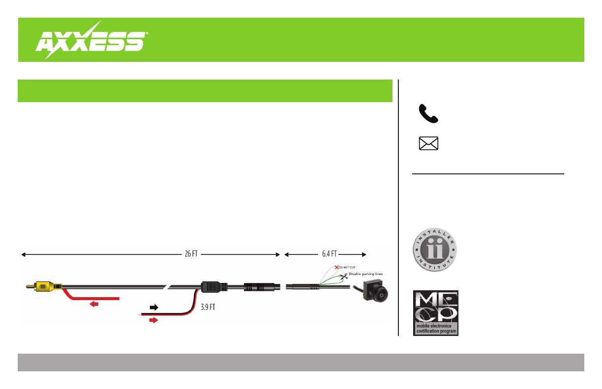
El cable ROJO en el RCA es el mismo cable que en la parte
posterior de 3.9 pies del arnés de extensión
• Cortar el circuito verde para agregar líneas de estacionamiento
• Ignore el bucle blanco (no se usa en esta aplicación)
• Salida RCA para los monitores o los radios genéricos
• Puede verse mientras conduce con un monitor compatible
• Carcasa plástica ABS para montar la cámara
• Cuatro (4) tornillos de acero inoxidable incluidos para fines de montura
• Sustituto directo de OE
• Resolución: Líneas de TV 550
• Líneas de estacionamiento seleccionables
• Ángulo de visualización: 160 grados
• Impermeable - IP68
El kit JP-JTKT incluye:
• Una (1) cámara y (1) cable de extensión
• Dos (2) soportes de montaje de cámara:
• Soporte con la etiqueta 1 para vehículos con cámara
de reversa.
• Soporte con la etiqueta 2 para vehículos con sistemas de
vista panorámica o 360º. (no se conserva)
• Instructivo
ESPECIFICACIONES
Cable ROJO = Alimentación de la cámara
Cable NEGRO = Conexión a tierra del chasis
  • Page 1 1
  • Page 2 2
  • Page 3 3
  • Page 4 4
  • Page 5 5
  • Page 6 6
  • Page 7 7
  • Page 8 8
  • Page 9 9
  • Page 10 10
  • Page 11 11
  • Page 12 12
  • Page 13 13
  • Page 14 14
  • Page 15 15
  • Page 16 16
  • Page 17 17
  • Page 18 18
  • Page 19 19
  • Page 20 20
  • Page 21 21
  • Page 22 22
  • Page 23 23
  • Page 24 24
  • Page 25 25
  • Page 26 26
  • Page 27 27
  • Page 28 28
  • Page 29 29
  • Page 30 30
  • Page 31 31
  • Page 32 32

Axxess AXPIO-JL1 Manual de usuario

Tipo
Manual de usuario

El Axxess AXPIO-JL1 es un dispositivo que permite la instalación de un radio Pioneer DMH-W4600NEX/WC4660NEX en un Jeep Wrangler JL del 2018 en adelante, manteniendo las funciones originales del vehículo como los controles de audio en el volante, la cámara de reversa y la pantalla de información del conductor. También permite la integración de una cámara frontal y un micrófono externo para llamadas telefónicas.

En otros idiomas