Kobalt KST 180-06 Manual de usuario
- Categoría
- Herramientas eléctricas
- Tipo
- Manual de usuario

1
PH19187
CORDED ELECTRIC
STRING TRIMMER
ITEM #XXXXXX
MODEL #KST 180-06
Español p. 23
Serial Number Purchase Date
Questions, problems, missing parts? Before returning to your retailer, call our customer
service department at 1-888-3KOBALT (1-888-356-2258), 8 a.m. - 8 p.m., EST,
Monday - Friday.
ATTACH YOUR RECEIPT HERE

2
TABLE OF CONTENTS
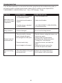
PRODUCT SPECIFICATIONS
SPECIFICATIONS
Input 120V, AC only, 60Hz, 10Amps
Speed
6,200 RPM ± 10%
Cutting path 18 in. (457 mm)
Line diameter 0.080 in. (2.0 mm)
Cutting capacity Dual line
Weight 7.7 lbs. (3.5 kg)
Product Specications...........................................................................................................2
Package Contents.................................................................................................................3
Hardware Contents..............................................................................................................4
Symbols................................................................................................................................ 5
Safety Information.................................................................................................................7
Preparation ......................................................................................................................... 11
Assembly Instructions ........................................................................................................ 11
Operating Instructions.........................................................................................................17
Care and Maintenance........................................................................................................19
Troubleshooting........................................................................................................................ 20
Warranty ................................................................................................................................ 21
Replacement Parts List.......................................................................................................22
FPO

3
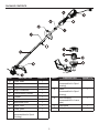
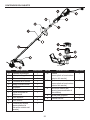
PART DESCRIPTION QUANTITY
A Power head 1
B Trigger 1
C Lock-off Lever 1
D Strap Connection 1
E Front/Auxiliary Handle 1
F Coupler 1
H Guard 1
I Attachment knob 1
J Upper Tube 1
K Lower Tube 1
L Spool Cover
(preassembled to Spool
Housing)
1
PART DESCRIPTION QUANTITY
M Spool
(preassembled to Spool
Housing)
1
N Eyelet
(preassembled to Spool
Housing)
1
O Spool Housing
(preassembled to Lower
Tube)
1
P Bump knob 1
S String Head 1
PACKAGE CONTENTS

4
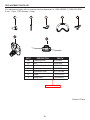
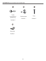
HARDWARE CONTENTS (not shown actual size)
Screw
(preassembled
to the Guard (H))
Qty. 4
Bracket
Qty. 1
Fastening Knob
Qty. 1
Bolt
Qty. 1

5
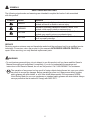
SYMBOLS
Some of the following symbols may be used on this product. Please study them and learn their mean-
ing. Proper interpretation of these symbols will allow you to operate the product better and safer.
SYMBOLS DESIGNATION EXPLANATION
V Volts Voltage
A Amperes Current
Hz Hertz Frequency (cycles per second)
W Watts Power
No Load Speed Rotational speed, at no load
Alternating Current Type of current
/min Per Minute
Revolutions, strokes, surface speed, orbits, etc., per
minute
Direct Current Type or a characteristic of current
Safety Alert Indicates a potential personal injury hazard.
Read The Operator’s Manual
To reduce the risk of injury, user must read and
understand operator’s manual before using this product.
Eye Protection
Always wear eye protection with side shields marked to
comply with ANSI Z87.1.
Wet Conditions Alert Do not expose to rain or use in damp locations.
No Blade
Do not install or use any type of blade on a
product displaying this symbol.
Ricochet
Thrown objects can ricochet and result in
personal injury or property damage.
Keep Bystanders Away Keep all bystanders at least 50 ft. away.
Class II Construction Double-insulated construction
Wet Conditions Alert Do not expose to rain or use in damp locations

6
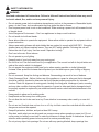
The following signal words and meanings are intended to explain the levels of risk associated
with this product.
WARNING
• To avoid serious personal injury, do not attempt to use this product until you have read this Owner's
Manual thoroughly and understand it completely. If you do not understand the warnings and
instructions in this Owner's Manual, do not use this product. Call 1-888-3KOBALT for assistance.
The operation of any power tool can result in foreign objects being thrown into your eyes, which
can result in severe eye damage. Before operating a power tool, always wear safety goggles,
safety glasses with side shields, or a full face shield when needed. We recommend a Wide
Vision Safety Mask for use over eyeglasses or standard safety glasses with side shields. Always
use eye protection that is marked to comply with ANSI Z87.1.
•
SYMBOL SIGNAL MEANING
DANGER
Indicates an imminently hazardous situation, which, if not
avoided, will result in death or serious injury.
WARNING
Indicates a potentially hazardous situation, which, if not
avoided, could result in death or serious injury.
CAUTION
Indicates a potentially hazardous situation, which, if not
avoided, may result in minor or moderate injury.
CAUTION
(Without Safety Alert Symbol) Indicates a situation that may
result in property damage.
SERVICE
Servicing requires extreme care and knowledge and should be performed only by a qualied service
technician. For service, return the product to your nearest AUTHORIZED SERVICE CENTER for
repair. When servicing, use only identical replacement parts.
SYMBOLS
SAVE THESE INSTRUCTIONS

7
SAFETY INFORMATION
WARNING
Read and understand all instructions. Failure to follow all instructions listed below may result
in electric shock, re, and/or serious personal injury.
• Do not operate power tools in explosive atmospheres, such as in the presence of ammable liquids,
gases, or dust. Power tools create sparks that may ignite the dust or fumes.
• Don’t expose power tools to rain or wet conditions. Water entering a power tool will increase the risk
of electric shock.
• Avoid Dangerous Environment – Don’t use appliances in damp or wet locations.
• Do not handle tool with wet hands.
• Never allow children to operate the equipment. Never allow adults to operate the equipment without
proper instruction.
• Always wear safety glasses with side shields that are marked to comply with ANSI Z87.1. Everyday
glasses have only impact resistant lenses. They are NOT safety glasses. Following this rule will
reduce the risk of eye injury. Use face mask if operation is dusty.
• Don’t use in the rain. Store indoors.
• Do not operate in poor lighting.
• Keep all parts of your body away from any moving part.
• Do not force tool. Use the correct tool for your application. The correct tool will do the job better and
safer at the rate for which it is designed.
• Do not operate the equipment while bare foot or when wearing sandals or similar lightweight
footwear. Wear protective footwear that will protect your feet and improve your footing on slippery
surfaces.
• Do not overreach. Keep rm footing and balance. Overreaching can result in loss of balance.
• Check Damaged Parts – Before further use of the appliance, a guard or other part that is damaged
should be carefully checked to determine that it will operate properly and perform its intended
function. Check for alignment of moving parts, binding of moving parts, breakage of parts, mounting
and any other condition that may affect its operation. A guard or other part that is damaged should,
be properly repaired or replaced by an authorized service center unless indicated elsewhere in this
manual.
• Keep guards in place and in working order.
• Keep hands and feet away from cutting area.
• Do not allow this tool to be used as a toy. Close attention is necessary when used by or near chil-
dren.
• Do not use tool if switch does not turn it on or off. Any tool that cannot be controlled with the switch is
dangerous and must be repaired.
• Keep all bystanders, children, and pets at least 50 ft. away.
• Stay alert, watch what you are doing and use common sense when operating a power tool. Do not
use a power tool while you are tired or under the inuence of drugs, alcohol or medication. A lapse of
attention while operating power tools may result in serious personal injury.
• Do not put any object into openings. Do not use with any opening blocked; keep openings free.

8
SAFETY INFORMATION
• Check the work area before each use. Remove all objects such as rocks, broken glass, nails, wire,
or string which can be thrown or become entangled in the machine.
• Use only identical manufacturer’s replacement parts and accessories. Use of any other parts may
create a hazard or cause product damage.
• For household use only.
• Store idle appliances - When not in use, the string trimmer should be stored indoors in a dry, locked
place out of the reach of children.
• Do not point the string trimmer in the direction of people or pets.
• Dress Properly – Do not wear loose clothing or jewelry. They can be caught in moving parts. Use of
rubber gloves and substantial footwear is recommended when working outdoors. Wear protective
hair covering to contain long hair.
• Use the Correct Appliance – Do not use appliance for any job except that for which it is intended.
• Use only with the nylon cutting line of 0.08” (2 mm) diameter. Do not use heavier lines than
recommended by the manufacturer and line materials of other types – for example, metal wire, rope,
and the like.
• Have servicing performed by a qualied repair person using only identical replacement parts. This
will ensure that the safety of the product is maintained.
• Maintain Appliance With Care – Replace string head if cracked, chipped, or damaged in any way. Be
sure the string head is properly installed and securely fastened. Keep cutting edge sharp and clean
for best performance and to reduce the risk of injury. Follow instructions for lubricating and changing
accessories. Inspect appliance cord periodically, and if damaged, have it repaired by an authorized
service facility. Inspect extension cords periodically and replace if damaged. Keep handles dry,
clean, and free from oil and grease. Failure to do so can cause serious injury.
• Disconnect Appliance – Remove appliance from power source before storing, servicing, changing
accessories such as cutting line. Such preventive safety measures reduce the risk of starting the tool
accidentally.
• Disconnect the plug from the power source and/or the battery pack from the power tool before
making any adjustments, changing accessories, or storing power tools. Such preventive safety
measures reduce the risk of starting the power tool accidentally.
• Warning – To reduce the risk of electric shock - Use outdoor extension cords marked W-A, W, SW-A,
SOW-A, STW-A, STOW-A, SJW-A, SJTW-A, or SJTOW-A. These cords are rated for outdoor use
and reduce the risk of electric shock.
• Do not abuse the cord. Never carry appliance by cord or yank it to disconnect from receptacle. Keep
cord from heat, oil, and sharp edges or moving parts. Damaged or entangled cords increase the risk
of electric shock.
• To reduce the risk of electric shock, this tool has a polarized plug (one blade is wider than the other)
and will require the use of a polarized extension cord. The plug will t into a polarized extension
cord only one way. If the plug does not t fully into the extension cord, reverse the plug. If the plug
still does not t, obtain a correct polarized extension cord. A polarized extension cord will require
the use of a polarized wall outlet. This plug will t into the polarized wall outlet only one way. If the
plug does not t fully into the wall outlet, reverse the plug. If the plug still does not t, contact a
qualied electrician to install the proper wall outlet. Do not change the equipment plug, extension
cord receptacle, or extension cord plug in any way.

9
SAFETY INFORMATION
Double insullated
Double insulation is a concept in safety in electric power tools, which eliminates the need for the
usual threewire grounded power cord. All exposed metal parts are isolated from the internal metal motor
components with protecting insulation. Double insulated tools do not need to be grounded.
The double insulated system is intended to protect the user from shock resulting from a break in the
tool’s internal insulation. Observe all normal safety precautions to avoid electrical shock.
NOTE: Servicing of a product with double insulation requires extreme care and knowledge of the sys-
tem and should be performed only by a qualied service technician. For service, we suggest you return
the tool to your nearest authorized service center for repair. Always use original factory replacement
parts when servicing.
Extension cords
When using a power tool at a considerable distance from a power source, be sure to use an extension
cord that has the capacity to handle the current the product will draw. An undersized cord will cause a
drop in line voltage, resulting in overheating and loss of power. Use the chart to determine the minimum
wire size required in an extension cord. Only round jacketed cords listed by Underwriter’s Laboratories
(UL) should be used.
When working outdoors with a product , use an extension cord that is designed for outside use. This
type of cord is designated with “W-A” or “W” on the cord’s jacket. Before using any extension cord,
inspect it for loose or exposed wires and cut or worn insulation.
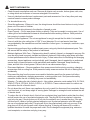
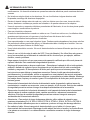
MINIMUM GAUGE FOR EXTENSION CORDS (AWG)
(WHEN USING 120 V ONLY)
Ampere Rating Total Length of Cord in Feet (meters)
More Than Not More Than 25' (7.6 m) 50' (15 m) 100' (30.4 m) 150' (45.7 m)
0 6 18 16 16 14
6 10 18 16 14 12
10 12 16 16 14 12
12 16 14 12 Not Recommended
Extension Cord – Make sure your extension cord is in good condition. When using an extension
cord, be sure to use one heavy enough to carry the current your product will draw. An undersized
extension cord will cause a drop in voltage resulting in loss of power and overheating. The table shows
the correct size to use depending on cord length and name plate ampere rating. If in doubt, use the next
heavier gauge. The smaller the gauge number, the heavier the cord. To reduce the risk of disconnection
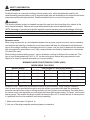
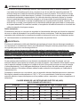
of appliance cord from the extension cord during operating:
1. Make a knot as shown in Figure A. or
2. Use one of the plug-receptacle retaining straps or connectors.
WARNING

10
METHOD OF SECURING EXTENSION CORD
(A) THE CORD AS SHOWN
(B) CONNECT PLUG AND RECEPTACLE
WARNING
Keep the extension cord clear of the working area. Position the cord so that it will not get caught on
lumber, tools, or other obstructions while you are working with a power tool. Failure to do so can result
in serious personal injury.
Check extension cords before each use. If damaged replace immediately. Never use the product with a
damaged cord since touching the damaged area could cause electrical shock resulting in serious injury.
SAFETY INFORMATION
Child safety
• Tragic accidents can occur if the operator is not aware of the presence of children.
• Keep children out of the working area and under the watchful care of a responsible adult.
• Do not allow children under the age of 14 to operate this trimmer. Children who are 14 years of age
or older must read and understand the operating instructions and safety rules in this manual and
must be trained and supervised by a parent.
• Stay alert and turn the trimmer off if a child or any other person enters the working area.
• Look behind and down for small children before and while cutting backwards.
• Use extreme care when approaching blind corners, doorways, shrubs, trees, or other objects that
may obscure your view of a child who may run into the path of the trimmer.
SAVE THESE INSTRUCTIONS

11
PREPARATION
ASSEMBLY INSTRUCTIONS
Hardware Used
Before beginning assembly of product, make sure all parts are present. Compare parts with
package contents list and hardware contents list. If any part is missing or damaged, do not attempt to
assemble the product.
Estimated Assembly Time: 5 - 10 minutes
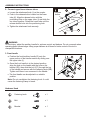
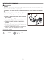
1. Guard
To avoid injury, always disconnect the power cord before installing the guard, changing a cutting line,
or making any adjustments.
If the guard is damaged, do not use the grass trimmer/edger until it is replaced.
Note: Install the protective guard before operating the grass trimmer/edger. It should not be
removed or disassembled.
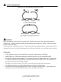
a. Invert the grass trimmer/edger to access the trimmer
head.
b. Using a Phillips head screwdriver, remove the
pre-installed screws (AA) from the trimmer head.
c. Place the guard (H) onto the trimmer head.
d. Align the screw holes on the guard with the screw
holes on the trimmer head.
e. Insert the screws into the trimmer head and tighten to
fasten the guard in place.
WARNING
Screw
x 4

12
ASSEMBLY INSTRUCTIONS
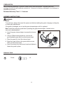
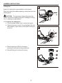
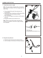
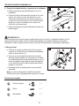
2. Connect upper/lower trimmer tubes
a. Loosen the attachment knob (I) on the coupler.
b. Push in the release button located on the lower
tube (K). Align the release button with the
positioning hole on the upper tube (J) and slide the
two tubes together. Rotate the lower tube until the
release button locks into the positioning hole.
b. Tighten the attachment knob securely.
To avoid injury, adjust the auxiliary handle for optimum control and balance. Do not overreach when
operating grass trimmer/edger. Keep proper balance at all times for better control of the tool in
unexpected situations.
3. Front handle
a. Position the front/auxiliary handle (E) onto the
upper portion of the trimmer section by sliding over
the upper tube (J).
b. Once the front handle is in the desired position,
align the hole on the handle with the hole on the
bracket (EE), then slide the bolt (CC) through the top
of the handle and secure with the fastening knob (BB).
Tighten until there is no movement in the handle.
c. The front handle can be adjusted to a suitable
position.
Note: Do not overtighten the fastening knob. It could
cause the fastening clamp to break.
WARNING
Hardware Used
Release
button
Positioning
hole
Fastening knob
Bolt
Bracket
x 1
x 1
x 1

13
ASSEMBLY INSTRUCTIONS
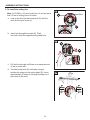
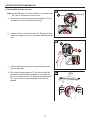
Cutting line
A spool of cutting line is pre-installed on the trimmer.
When the cutting line needs replacing, rewind new line onto
existing spool.
CAUTION: To avoid injury, always disconnect the
power cord before installing the guard, changing a cutting
line, or making any adjustments.
4. To remove the cutting line :
a. Turn the string trimmer over to access the spool.
b. Remove the spool cover (L) by pressing on the two
tabs parallel to each other on the sides of the spool
cover (L).
c. Remove the spool (M) from the spool
housing (O) and remove any excess line.
d. Reinstall the spool and spool housing.
Tab

14
ASSEMBLY INSTRUCTIONS
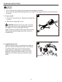
5. To Install the cutting line
Note: For 0.080 in. (2.0 mm) nylon line, do not put more
than 13 feet of cutting line in at a time.
a. Line up the slots on the bump knob (P) with the
slots on the spool cover (L).
b. Insert line through the eyelet (N). Push
line until it exits the opposite string head hole.
c. Pull the line through until there is an equal amount
of line on each side.
d. Turn the bump knob (P) clockwise to begin
winding the string into the string head (S). Leave
approximately 5 inches of string protruding out of
each side of the head.
Slots

15
ASSEMBLY INSTRUCTIONS
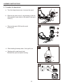
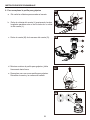
6. To replace the bump knob
a. Turn the string trimmer over to access the spool.
b. Remove the spool cover (L) by pressing on the two
tabs parallel to each other on the sides of the spool
cover (L).
c. Remove the spool (M) from the spool
housing (O).
d. While holding the bump knob , rmly pull it out.
e. Replace with a new bump knob .
Reinstall the spool and spool housing.
6a
6b
6c

16
ASSEMBLY INSTRUCTIONS
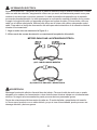
7. Connecting to power supply
Note: The power head is designed with a cord retainer
that prevents the extension cord from being pulled loose
while using.
a. Form a loop with the end of the extension cord
(not included).
b. Insert loop portion of extension cord through opening
in the bottom of the rear handle and place
over cord retainer.
c. Slowly pull loop against cord retainer until the slack is
removed.
d. Plug power head (A) into extension cord.
Note: Failure to remove all excess cord slack from
extension cord retainer could result in plug loosening
from receptacle.
8. Using the strap harness
a. Rotate the strap harness to the upward position.
b. Hook the strap (not included) to the strap connection.
1) 2-prong plug
2) Properly grounded extension cord
Strap
Connection

17
WARNING
To avoid injury:
• Do not squeeze the trigger while the grass trimmer/edger is inverted.
• Do not carry the grass trimmer/edger with your nger on the trigger (switch) to avoid unintention-
al starting.
1. To turn on/off:
a. Press the lock-off lever (C). Squeeze the trigger (B)
to start.
b. Release the trigger (B) to stop.
CAUTION: Always allow 5 seconds or more for
the cutting line spool to stop rotating after releasing
the trigger. Do not invert the grass trimmer/
edger or place your hands under the protective guard
until the grass trimmer/edger spool has come to a
complete stop.
2. Lengthening the line
While the string trimmer is operating, the cutting line
gets worn down and becomes shorter. This trimmer
is equipped with bump feed line advancement,
which advances additional line once the head is
bumped on the ground while rotating. The cut-off
blade will cut the line to keep an accurate cutting
swath.
OPERATING INSTRUCTIONS
Bump knob
9
10

18
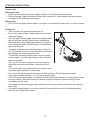
OPERATING INSTRUCTIONS
Trimmer tips
Before each use:
• Make sure the protective guard is tightly installed. If not, tighten the guard screws.
• Before trimming, inspect the area for string, wire, branches or other material that may become
entangled in the cutting line and thrown.
Storage tips:
• Do not store the grass trimmer/edger in sunlight, in an excessively warm place, or near a furnace.
During use:
• Trim only when the grass and weeds are dry.
• Do not trim grass at night. Always make sure you have
adequate lighting.
• Hold the grass trimmer/edger by both the switch handle
and the auxiliary handle for best control and balance.
• Stand with the cutting head tipped down at an angle in
front, guiding the grass trimmer/edger in a semicircular
motion around you.
• If possible, guide the grass trimmer/edger to the left to
cut. The line will cut as soon as it leaves the guard, and
the clippings are thrown away from you.
• To produce a smoothly trimmed area, move the grass
trimmer/edger out of the area being cut with consistent
speed and height.
• Use only the tip of the cutting line to do the trimming,
especially near walls and fences. Trimming with the
side
of the cutting line may overload the motor, wear out the
line faster, and break the line more often.
• Do not rest the trimmer spool on the ground while trimming. This will cause spool wear.
• If the grass is higher than 6 in. (15 cm), trim in small stages.
• When the grass trimmer/edger is turned off and the spool stops rotating, the cutting line will relax
and may recede. Feed extra cutting line before storing the trimmer to prevent losing the line
completely into the spool.
• If the diameter of the cutting area gets smaller, the line is worn down and needs to be advanced
more often.
• If the grass trimmer/edger is not cutting correctly, the cutting line may not be feeding properly.
• Remove and rewind the line spool.

19
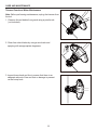
CARE AND MAINTENANCE
Trimmer Guard and Motor Maintenance
Note: Before performing maintenance, unplug the trimmer from
the tool.
1. Remove dirt and debris from guard using a paint brush
(not included).
2. Clean line cutter blades by using a wire brush and
spraying with an appropriate degreaser.
3. Inspect bump knob and line to ensure that there is an
adequate amount of line and that no damage is present
on the bump knob.

20
TROUBLESHOOTING
PROBLEM POSSIBLE CAUSE CORRECTIVE ACTION
Motor fails to start
when switch trigger
is depressed.
1. Power cord is not plugged in
or connection is loose.
2. Household circuit breaker is
tripped.
3. Possible wiring or electrical
contact problem.
1. Plug in the power cord.
2. Check circuit breaker.
3. Call 1-888-3KOBALT (1-888-356-2258)
for technical service.
Trimmer smokes
during operation. 1. Trimmer damaged. 1. Do not use the string trimmer.
Trimmer head will
not advance line.
1. The motor shaft or trimmer
head is bound with grass.
2. Not enough line in the spool.
3. Trimmer head is dirty.
4. Line is tangled on the spool.
1. Stop the trimmer, unplug the trimmer, and
remove any grass.
2. Unplug power cord and replace
the trimmer line. Reference section
"Cutting Line" in this manual.
3. Unplug the trimmer, and clean the
spool.
4. Unplug the trimmer, remove the
line from the spool and rewind.
Line is not cutting
well.
1. The cutting blade on the guard
has become dull.
1. Sharpen the cutting blade with a
le or replace it with a new blade.
If you still have questions or an unresolved issue after going through this troubleshooting guide, or
just want to speak to a Kobalt product expert, please call our customer service department at
1-888-3KOBALT (1-888-356-2258), 8 a.m. - 8 p.m., EST, Monday – Friday.

21
WARRANTY
5-YEAR LIMITED WARRANTY
This Kobalt electric String Trimmer is warranted to the original purchaser from the original purchase
date for ve (5) years subject to the warranty coverage described herein.
This Kobalt electric String Trimmer is warranted for the original user to be free from defects in material
and workmanship.
If you believe that the kobalt electric String Trimmer is defective at any time during the specied war-
ranty period, simply return the electric String Trimmer along with proof of purchase to the place of
purchase for a free replacement or refund, or call 1-888-3KOBALT (1-888-356-2258) for warranty
service.
This warranty is void if: defects in materials or workmanship or damages result from repairs or
alterations which have been made or attempted by others or the unauthorized use of nonconforming
parts; the damage is due to normal wear, damage is due to abuse (including overloading of the tool
beyond capacity), improper maintenance, neglect or accident; or the damage is due to the use of the
tool after partial failure or use with improper accessories or unauthorized repair or alteration.
This warranty excludes spool.
This warranty gives you specic legal rights, and you may also have other rights that vary from state
to state.

22
REPLACEMENT PARTS LIST
For replacement parts, call our customer service department at 1-888-3KOBALT (1-888-356-2258),
8 a.m. - 8 p.m., EST, Monday - Friday.
PART DESCRIPTION PART #
BB Fastening knob 341201444
CC Bolt 322051444
E Front/auxiliary handle 341191444A
EE Bracket 33304877B
I Attachment knob 341111437AB
H Guard C1101015-00
S String head C1100993-00
Printed in China
FPO

23
¿Tiene preguntas, problemas, piezas faltantes? Antes de regresar al vendedor, llame a
nuestro Departamento de Servicio al Cliente al 1-888-3KOBALT (1-888-356-2258) de lunes
a viernes, de 8 a.m. a 8 p.m., hora estándar del Este.
ADJUNTE SU RECIBO AQUĺ
arpmoc ed ahceF eires ed oremúN
ORILLADORA
ELÉCTRICA CON CABLE
ARTÍCULO #XXXXXX
MODELO #KST 180-06

24
CONTENIDO
ESPECIFICACIONES DEL PRODUCTO
ESPECIFICACIONES
Entrada 120 V, CA únicamente, 60 Hz, 10 amperios
Velocidad
6,200 RPM ± 10%
Amplitud de corte 18 pulg. (457 mm)
Diámetro de la línea 0,080 pulg. (2,0 mm)
Capacidad de corte Hilo dual
Peso 7,7 lbs. (3,5 kg)
Especicaciones del producto...........................................................................................24
Contenido del paquete........................................................................................................25
Aditamentos.............................................................................................................26
Símbolos..............................................................................................................................27
Información de segurdad...................................................................................................29
Preparación ......................................................................................................................... 33
Instrucciones de ensamblaje .......................................................................................... 34
Instrucciones de uso.........................................................................................................40
Cuidado y mantenimiento....................................................................................................42
Detección de problemas.................................................................................................... 43
Garantía................................................................................................................................44
Lista de repuestos.............................................................................................................45

25
PIEZA DESCRIPCIÓN CANTIDAD
A Cabezal de potencia 1
B Interruptor de gatillo 1
C Palanca de bloqueo 1
D Conexión de la correa 1
E Mango auxiliar/frontal 1
F Acoplador 1
H Protector 1
I Perilla de ajuste de
aditamentos
1
J Tubo superior 1
K Tubo inferior 1
L Cubierta del carrete
(preacoplada a la
estructura exterior del
carrete)
1
PIEZA DESCRIPCIÓN CANTIDAD
M Carrete
(preacoplado a la estructura
exterior del carrete)
1
N Ojal
(preacoplada a la estructura
exterior del carrete)
1
O Estructura exterior del
carrete (preensamblado al
tubo inferior)
1
P Perilla para golpeteo 1
S Cabezal de hilo 1
CONTENIDOS DEL PAQUETE

26
ADITAMIENTOS (no se muestran en el tamaño real)
Tornillo
(preacoplado al
protector (H))
Cantidad: 4
Abrazadera
Cantidad: 1
Perilla de ajuste
Cantidad: 1
Perno
Cantidad: 1

27
SÍMBOLOS
Algunos de estos símbolos pueden ser usados en este producto. Por favor, léalos y aprenda su
signicado. La interpretación correcta de estos símbolos permite una operación mejor y más segura.
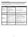
SÍMBOLOS DESIGNACIÓN EXPLICACIÓN
V Voltios Voltaje
A Amperios Corriente
Hz Hercios Frecuencia (ciclos por segundo)
W Vatios Potencia
Velocidad sin carga Velocidad racional, sin carga
Corriente alterna Tipo de corriente
/min Por minuto
Revoluciones, cortes, velocidad sobre la supercie,
órbitas, etc., por minuto.
Corriente continua Tipo o característica de la corriente
Alerta de seguridad Precauciones para su seguridad.
Lea el manual del operario
Para reducir el riesgo de lesiones, el usuario
debe leer y comprender el manual del
operario antes de usar este producto.
Protección para los ojos
Cuando use este equipo, use protección para
los ojos con cobertura lateral que cumpla con
los requisitos de la ANSI Z87.1.
Alerta sobre el uso en áreas
mojadas
No exponga la orilladora a la lluvia ni la use
en áreas húmedas.
Sin hoja
No instale ni use ningún tipo de hoja en un
producto que tenga este símbolo.
Rebote
Los objetos lanzados por el producto pueden
rebotar y ocasionar lesiones o daños
materiales.
Evite la cercanía de personas
Mantenga una distancia mínima de 15,24 m
de otras personas cuando use la orilladora.
Construcción de clase II Fabricación con doble aislamiento.
Alerta sobre el uso en áreas
mojadas
No exponga la orilladora a la lluvia ni la use
en áreas húmedas.

28
La simbología y signicados siguientes fueron diseñados para explicar los niveles de riesgo
asociados con este producto.
ADVERTENCIA
• Para prevenir lesiones personales severas, no intente usar este producto sin haber leído y entendido
completamente este manual del propietario. Si usted no entiende las advertencias e instrucciones en
este manual del propietario, no use este producto. Llame al 1-888-356-2258 para recibir asistencia.
El funcionamiento de cualquier herramienta eléctrica puede causar que objetos sean
lanzados hacia sus ojos, lo que puede ocasionar lesiones severas en los ojos. Antes de
comenzar a usar herramientas eléctricas, use siempre gafas protectoras o anteojos de
seguridad con protectores laterales y, si fuera necesario, una máscara protectora total.
Recomendamos una máscara de seguridad de visión amplia para usar sobre anteojos o
gafas de seguridad estándar con protectores laterales. Use siempre protección para los ojos
que cumpla con la ANSI Z87.1.
•
SÍMBOLO SEÑAL SIGNIFICADO
PELIGRO
Indica una situación de peligro inminente que, si no es
prevenida, causará la muerte o lesiones severas.
ADVERTENCIA
Indica una situación de peligro potencial que, si no es
prevenida, podría causar la muerte o lesiones severas.
PRECAUCIÓN
Indica una situación de peligro potencial que, si no es
prevenida, puede causar lesiones menores o moderadas.
PRECAUCIÓN
(Sin el símbolo de alerta de seguridad) Indica una situación
que puede causar daños materiales.
MANTENIMIENTO
El servicio de la producto requiere extremo cuidado y conocimientos técnicos, por lo cual solo debe ser
efectuado por un tecnico de servicio calicado. Para realizar el mantenimiento, le recomendamos llevar
el producto al CENTRO DE SERVICIO AUTORIZADO más cercano para su reparación. Al realizar
mantenimiento, utilice solo piezas de repuesto idénticas.
SÍMBOLOS
Guarde estas instrucciones

29
INFORMACIÓN DE SEGURIDAD
ADVERTENCIA
• No opere herramientas eléctricas en ambientes explosivos tales como en la presencia de líquidos
inamables, gases, o polvo. Las herramientas eléctricas crean que pueden incendiar el polvo o los
gases.
• No exponga las herramientas eléctricas a la lluvia ni a las condiciones mojadas. La entrada de agua
a una herramienta eléctrica aumenta el riesgo de la descargas eléctricas.
• Evite condiciones peligrosas. No use la máquina bajo la lluvia ni en césped mojado o húmedo.
• No manipule la herramienta con las manos mojadas.
• Nunca permita que los niños operen este equipo. Nunca permita que los adultos operen este equipo
sin la capacitación adecuada.
• Use siempre gafas de seguridad con protectores laterales que cumplan con los requisitos de
la ANSI Z87.1. Las gafas comunes solo tienen lentes resistentes las golpes, NO son gafas de
seguridad. El cumplimiento de esta regla reduce el riesgo de lesiones en los ojos, use una máscara
si hay polvo durante la operación.
• No la exponga a la lluvia. Guárdela en interiores.
• No la use en lugares con poca iluminación.
• Mantenga todas las partes de su cuerpo alejadas de las piezas en movimiento.
• No fuerce esta herramienta. Use la herramienta correcta para cada aplicación, la herramienta
adecuada funcionará mejor y de manera más segura si se usa al ritmo para el cual fue diseñada.
• No opere este equipo descalzo o cuando use sandalias o calzado ligero similar. Use calzado que
proteja sus pies y asegure sus pasos en supercies resbalosas.
• Mantenga sus pies rmes y un buen equilibrio, no se extralimite al tratar de alcanzar, ya que puede
resultar en la pérdida del equilibrio.
• Verique que no haya piezas dañadas: antes de seguir utilizando el electrodoméstico, debe
vericar detenidamente que los protectores, o cualquier otra pieza dañada, funcionen correctamente
y realicen la función deseada. Verique la alineación y el trabamiento de las piezas móviles, la
ruptura de las piezas, la instalación y cualquier otro tipo de condición que pueda afectar el funciona-
miento. Si una cubierta o cualquier otra pieza están dañadas, deben repararse o reemplazarse de
inmediato en un centro de servicio autorizado, a menos que se indique otro lugar en este manual.
• Mantenga los topes en su lugar y en buenas condiciones de funcionamiento.
• Mantenga las manos y los pies alejados del área de corte.
• No permita que la herramienta se use como juguete. Preste atención cuando sea usada por y cerca
de los niños.
• No la use si el interruptor de encendido/apagado no funciona. Una herramienta que no se puede
controlar con el interruptor es peligrosa y debe ser reparada.
• Mantenga una distancia de 15,24 m de las personas, los niños y las mascotas cuando use la orilladora.
• Manténgase alerta, fíjese en lo que está haciendo y utilice el sentido común cuando opere una
herramienta eléctrica. No la utilice cuando esté cansado o bajo la inuencia del alcohol, drogas o
Lea y asegúrese de comprender todas las instrucciones antes de usar este producto. Si no se
siguen todas las instrucciones mencionadas a continuación, pudieran producirse descargas
eléctricas, incendios y/o lesiones severas.

30
INFORMACIÓN ELÉCTRICA
medicamentos. Un descuido mientras se operan herramientas eléctricas puede ocasionar lesiones
severas.
• No introduzca ningún objeto en las aberturas. No use la orilladora si alguna abertura está
bloqueada, mantenga las aberturas despejadas.
• Revise el área de trabajo antes de cada uso, quite los objetos como las rocas, trozos de vidrio,
clavos, alambres o cuerdas que puedan ser lanzados o se puedan atascar en la máquina.
• Use solo repuestos y accesorios idénticos procedentes del fabricante, el uso de otras piezas puede
crear riesgos o causar daños al producto.
• Para uso doméstico solamente.
• Guarde los electrodomésticos cuando no estén en uso. Cuando no esté en uso, la orilladora debe
guardarse en interiores en un lugar seco y bajo llave fuera del alcance de los niños.
• No apunte la orilladora hacia personas o mascotas.
• Use ropa adecuada: no use ropa holgada ni joyas. Pueden quedar atrapadas en las piezas móviles.
Se recomienda utilizar guantes de goma y un calzado adecuado si trabaja en el exterior. Use una
malla protectora para contener el cabello largo.
• Use el electrodoméstico correcto. No use el electrodoméstico en tareas diferentes para las que fue
diseñado.
• Use solo con un hilo de corte de nailon de 0,08” (2 mm de diámetro). No utilice hilos más gruesos
que el recomendado por el fabricante ni materiales de hilo de otros tipos; por ejemplo, alambre
metálico, cuerda y similares.
• Haga reparar el producto solo por una persona de reparación calicada que utilice solo piezas de
repuesto idénticas. Esto mantendrá la seguridad del producto.
• Mantenga la herramienta en buenas condiciones – Reemplace el cabezal de hilo si está agrietado,
astillado o dañado de cualquier forma. Asegúrese de que el cabezal de hilo esté correctamente
instalado y asegurado. El incumplimiento de dicho paso podría provocar lesiones graves. Siga
las instrucciones para lubricar y reemplazar accesorios. Revise el cable para electrodoméstico
periódicamente y, si está dañado, solicite su reparación en una instalación de servicio autorizada.
Inspeccione periódicamente las extensiones eléctricas y reemplácelas si están dañadas. Mantenga
las manijas secas, limpias y sin aceite ni grasa. El incumplimiento de dicho paso podría provocar
lesiones graves.
• Desconecte la herramienta de la fuente de alimentación antes de guardarla, realizar tareas de
mantenimiento o cambiar sus accesorios, como por ejemplo, el hilo de corte. Este tipo de medidas
de seguridad preventiva reduce el riesgo de arranques accidentales de la herramienta.
• Desconecte el enchufe de la fuente de alimentación o del paquete de baterías de la herramienta
eléctrica antes de realizar cualquier ajuste, cambiar accesorios o almacenar herramientas
eléctricas. Este tipo de medidas de seguridad preventivas reduce el riesgo de arranques
accidentales de la herramienta eléctrica.
• Advertencia – Para reducir el riesgo de descarga eléctrica, utilice cables de extensión para
exteriores etiquetados W-A, W, SW-A, SOW-A, STW-A, STOW-A, SJW-A, SJTW-A o SJTOW-A.
Estos cables están calicados para uso en exteriores y reducen el riesgo de descarga eléctrica.
• No maltrate el cable. Nunca transporte el electrodoméstico por el cable ni lo tironee para
desconectarlo del tomacorriente. Mantenga el cable alejado del calor, el aceite y los bordes losos
o las piezas en movimiento. Los cables dañados o enredados aumentan el riesgo de descarga
eléctrica.

31
• Para reducir el riesgo de descarga eléctrica, esta herramienta posee un enchufe polarizado
(una clavija es más ancha que la otra) y requiere el uso de un cable de extensión polarizado. El
enchufe encaja en el cable de extensión polarizado de una sola manera. Si el enchufe no encaja
completamente en el cable de extensión, inviértalo. Si el enchufe aún no encaja, adquiera el cable
de extensión polarizado correspondiente. Un cable de extensión polarizado requiere un tomacor-
riente de pared polarizado. El enchufe encajará en el tomacorriente de pared polarizado de una
sola manera. Si el enchufe no encaja completamente en el tomacorriente de pared, inviértalo. Si el
enchufe aún no encaja, comuníquese con un electricista calicado para que instale un tomacorrien-
te de pared adecuado. No cambie el enchufe, el receptáculo del cable de extensión o el enchufe del
cable de extensión de ninguna manera.
Doble aislamiento
El aislamiento doble es un concepto de seguridad en herramientas eléctricas que elimina la necesidad
de usar un cable de alimentación con puesta a tierra de tres conductores. Todas las piezas metálicas
expuestas están aisladas de los componentes metálicos internos del motor con un aislamiento protec-
tor. Las herramientas con aislamiento doble no necesitan una puesta a tierra.
El sistema de aislamiento doble está diseñado para proteger al usuario de una descarga causada por
un rompimiento en el aislamiento interno de la herramienta. Respete todas las precauciones normales
de seguridad para evitar una descarga eléctrica.
NOTA: solo un técnico de servicio calicado debe realizar el mantenimiento a un producto con
aislamiento doble, quien debe conocer el sistema y trabajar con sumo cuidado. Para realizar el manten-
imiento, le recomendamos llevar la herramienta al centro de servicio autorizado más cercano para su
reparación. Use siempre las piezas de repuestos originales de fábrica al realizar el mantenimiento.
Extensiones eléctricas
Al usar una herramienta eléctrica a una distancia considerable de la fuente de energía, use una
extensión eléctrica que soporte la corriente que usará el producto. Una extensión de un tamaño menor
que el requerido causará una baja en el voltaje de la línea. Esto podría provocar un corte de energía
y sobrecalentamiento. Use la tabla para determinar el tamaño mínimo de cable necesario para una
extensión eléctrica. Solo deben utilizarse cables forrados redondos homologados por Underwriter’s
Laboratories (UL).
Al trabajar en exteriores con un producto, use una extensión eléctrica diseñada para uso en exteriores.
Este tipo de extensión está marcada con “W-A” o “W” en su revestimiento. Antes de usar cualquier
extensión eléctrica, inspecciónela para ver si hay cables sueltos o expuestos, o cortes o desgaste en el
aislamiento.
CALIBRE MÍNIMO DE LAS EXTENSIONES ELÉCTRICAS (AWG)
(SÓLO CUANDO UTILIZA 120 V)
Amperaje Longitud total del cable en metros (pies)
Más de No más de 7,6 m (25 ft) 15 m (50 ft) 30,4 m (100 ft) 45,7 m (150 ft)
0 6 18 16 16 14
6 10 18 16 14 12
10 12 16 16 14 12
12 16 14 12 No se recomienda
ADVERTENCIA
INFORMACIÓN ELÉCTRICA

32
INFORMACIÓN ELÉCTRICA
Extensiones eléctricas – Asegúrese de que su cable de extensión esté en buenas condiciones. Cuando
utilice un cable de extensión, asegúrese de utilizar uno que sea lo sucientemente pesado como para
conducir la corriente que su producto necesita. Un cable de tamaño más pequeño que el requerido
provocará sobrecalentamiento. La tabla que aparece a continuación muestra el tamaño de uso correc-
to según la longitud del cable y el amperaje que gura en la placa de datos. Si tiene dudas, utilice un
cable con el calibre subsiguiente. Mientras más chico sea el número del calibre, más pesado será el
cable. Para reducir el riesgo de desconexión del cable para electrodoméstico de la extensión eléctrica
durante el funcionamiento:
1. Haga un nudo como se muestra en la Figura A, o
2. Utilice una de las correas de retención o conectores del receptáculo del enchufe.
MÉTODO PARA FIJAR LA EXTENSIÓN ELÉCTRICA
(A) EL CABLE COMO SE MUESTRA
(B) CONECTE EL ENCHUFE Y RECEPTÁCULO
ADVERTENCIA
Mantenga la extensión eléctrica fuera del área de trabajo. Coloque el cable de modo que no quede
atrapado en la madera, las herramientas u otras obstrucciones mientras trabaja con una herramienta
eléctrica. No seguir esta recomendación puede provocar lesiones personales graves.
Revise las extensiones eléctricas antes de cada uso. Si están dañadas, reemplácelas de inmedia-
to. Nunca use el producto con un cable dañado, ya que si toca el área dañada, puede provocar una
descarga eléctrica y lesiones graves.

33
Seguridad infantil
Pueden ocurrir accidentes trágicos si el operario no tiene conocimiento de la presencia de los niños.
• Mantenga a los niños fuera del área de trabajo y bajo la estricta vigilancia de un adulto responsable.
• No permita que los niños menores de 14 años operen esta orilladora. Los niños de 14 años de
edad o más deben leer y entender las instrucciones de operación y las normas de seguridad
mencionadas en este manual y deben ser capacitados y supervisados por sus padres.
• Manténgase alerta y apague el aparato si un niño o cualquier otra persona entra en la zona de
trabajo.
• Mire hacia atrás y hacia abajo, antes y durante el corte hacia atrás, para ver si hay niños pequeños.
• Tenga extrema precaución cuando se aproxime a las esquinas ciegas, entradas, arbustos, árboles
u otros objetos que pudieran evitar que se vea la presencia de un niño que podría atravesarse en el
camino de la orilladora.
GUARDE ESTAS INSTRUCCIONES
INFORMACIÓN ELÉCTRICA
PREPARACIÓN
Antes de empezar a ensamblar el producto, asegúrese de tener todas las piezas. Compare las
piezas con la lista del contenido del paquete y la lista de aditamentos. Si hubiera alguna pieza
faltante o dañada, no trate de ensamblar el producto.
Tiempo aproximado para el ensamblaje: 5 a 10 minutos

34
INSTRUCCIONES DE ENSAMBLAJE
Herramientas usadas
1. Protector
Para evitar daños, siempre desconecte el cable de alimentación antes de instalar el protector, cam-
biar la línea de corte o hacer cualquier ajuste.
Si el protector está dañado, no utilice la orilladora/bordeadora de césped hasta que sea reemplaza-
do.
Nota: instale el protector antes de utilizar la orilladora/
bordeadora de césped, ya que no se puede quitar o
desarmar.
a. Invierta la orilladora para obtener acceso al cabezal
de la orilladora.
b. Use un destornillador Phillips para retirar los tornillos
preinstalados (AA) del cabezal de la orilladora.
c. Coloque el protector (H) contra el cabezal de la
orilladora.
d. Alinee los oricios para los tornillos del protector con
los oricios en el cabezal de corte.
e. Inserte los tornillos en el cabezal de la cortadora de
orillas y apriete para asegurarlos en su lugar.
ADVERTENCIA
Tornillo
x 4

35
INSTRUCCIONES DE ENSAMBLAJE
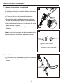
2. Conecte los tubos inferior y superior de la orilladora
a. Aoje la perilla para ajustar aditamentos (I) en el
acopladoe.
b. Presione el botón de liberación ubicado en el tubo
inferior (K). Alinee el botón de liberación con el
oricio de posicionamiento en el tubo superior (J)
y deslice los dos tubos juntos. Rote el tubo inferior
hasta que el botón de liberación se trabe en el
oricio de posicionamiento.
c. Apriete la perilla para ajustar aditamentos hasta que
quede segura.
Para evitar lesiones, ajuste el mango auxiliar para tener un control y un equilibrio óptimos. No se
extienda demasiado cuando utilice la orilladora/bordeadora de césped. Mantenga el equilibrio
adecuado en todo momento para un mejor control de la herramienta en situaciones inesperadas.
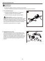
3. Mango frontal
a. Coloque el mango auxiliar/frontal (E) en la parte
superior de la sección de la orilladora deslizándolo
sobre el tubo superior (J).
b. Una vez que la manija frontal esté en la posición
deseada, alinee el oricio en la manija con el oricio
en la abrazadera (EE), luego deslice el perno (CC) a
través de la parte superior de la manija y asegúrelo
con la perilla de sujeción (BB). Apriete hasta que el
mango no se mueva.
c. El mango frontal se puede ajustar a una posición
adecuada.
Nota: no apriete demasiado la perilla de sujeción.
Podría hacer que la abrazadera de sujeción se rompa.
ADVERTENCIA
Herramientas usadas
Botón de
liberación
Oricio de
posicionamiento
Perilla de ajuste
Perno
Abrazadera
x 1
x 1
x 1

36
INSTRUCCIONES DE ENSAMBLAJE
Línea de corte
Se ha instalado previamente un carrete de línea de corte en
la bordeadora de césped.
Cuando las líneas de corte requieran reemplazo, rebobine la
línea nueva en el carrete existente.
PRECAUCIÓN: para evitar lesiones, retire siempre
la batería antes de instalar el protector, cambiar la línea de
corte o hacer cualquier ajuste.
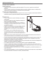
4. Para retirar la línea de corte:
a. Dele la vuelta a la orilladora para tener acceso al
carrete.
b. Quite la cubierta del carrete (L) presionando las dos
lengüetas paralelas entre sí en el lado de la cubierta
del carrete (L).
c. Retire el carrete (M) de la carcasa del carrete (O)
y retire el exceso de línea.
d. Reinstale el carrete y la carcasa del carrete.
lengüeta

37
INSTRUCCIONES DE ENSAMBLAJE
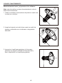
5. Para instalar la línea de corte
Nota: para 0,080 pulg. (2,0 mm) de línea, no coloque más
de 3,96 m de línea de corte a la vez.
a. Alinee las ranuras en la perilla para golpeteo (P) con
las ranuras en la cubierta del carrete (L).
b. Inserte la línea a través del ojala (N). Empuje la línea
hasta que salga por el oricio opuesto del cabezal de
hilo.
c. Jale la línea hasta que haya una cantidad igual de
línea a cada lado.
d. Gire la perilla para golpeteo (P) en dirección de las
manecillas del reloj para comenzar el enrollado del
hilo en el cabezal de hilo (S). Deje aproximadamente
12,7 cm de hilo que sobresalga de cada lado del
cabezal.
Ranuras

38
INSTRUCCIONES DE ENSAMBLAJE
6. Para reemplazar la perilla para golpeteo
a. Dé vuelta la orilladora para acceder al carrete.
b. Retire la cubierta del carrete (L) presionando las dos
lengüetas paralelas entre sí en los lados de l a cubier
ta del carrete (L).
c. Retire el carrete (M) de la carcasa del carrete (O).
d. Mientras sostiene la perilla para golpeteo, jálela
rmemente hacia fuera.
e. Reemplace con una nueva perilla para golpeteo.
Reinstale el carrete y la carcasa del carrete.
6a
6b
6c

39
INSTRUCCIONES DE ENSAMBLAJE
7. Conexión al suministro de electricidad
Nota: el cabezal de potencia se diseñó con un retenedor
del cable que evita que la extensión eléctrica se suelte al
jalarla mientras se usa.
a. Forme un bucle con el extremo de la extensión
eléctrica (no se incluye).
b. Inserte la parte del bucle de la extensión eléctrica
a través de la abertura en la parte inferior del mango
posterior y coloque sobre el retenedor del cable.
c. Jale lentamente el bucle contra el retenedor del cable
hasta eliminar la holgura.
d. Enchufe el cabezal de potencia (A) en la extensión
eléctrica.
Nota: si no elimina la holgura del cable excedente de la
extensión eléctrica, el retenedor se podría soltar del
tomacorriente.
8. Uso del arnés con correa
a. Gire el arnés con correa hasta la posición hacia arriba.
b. Enganche la correa (no se incluye) a la conexión de la
correa.
1) Enchufe de 2 clavijas
2) Cable de extensión con
conexión a tierra adecuada
Conexión
de la correa

40
ADVERTENCIA
Para evitar lesiones:
• No apriete el gatillo mientras la orilladora esté invertida.
• No lleve la orilladora con el dedo en el interruptor. Evite el arranque accidental.
1. Para encender/apagar:
a. Presione la palanca de bloq ueo (C). Apriete el
interruptor de gatillo (B) para encenderla.
b. Suelte el interruptor de gatillo (B) para detener.
PRECAUCIÓN: deje pasar siempre unos 5
segundos o más para que el carrete de la línea de corte
deje de girar después de soltar el interruptor de gatillo.
No invierta la orilladora/bordeadora ni coloque las manos
bajo el protector hasta que el carrete de la orilladora/
bordeadora se haya detenido por completo.
2. Alargamiento de la línea
Mientras la orilladora está en funcionamiento, el hilo
de corte se desgasta y se acorta. Esta podadora está
equipada con avance de hilo por contacto, lo que
permite que el hilo salga cuando se golpea suavemente
el suelo con el cabezal mientras rota. La hoja de corte
recortará el hilo para mantener la amplitud de corte
precisa.
INSTRUCCIONES DE USO
Perilla para
golpeteo
9
10

41
INSTRUCCIONES DE USO
Consejos sobre la podadora
Antes de cada uso:
• Asegúrese de que el protector esté bien instalado. De no ser así, apriete los tornillos del
protector.
• Antes de podar, inspeccione el área para detectar cuerdas, alambres, ramas o cualquier otro
material que pueda enredarse en la línea de corte y ser lanzado.
Consejos para el almacenamiento:
• No guarde la orilladora/bordeadora expuesta a la luz solar, en lugares excesivamente cálidos ni
cerca de un horno ya que esto reducirá la duración de la batería.
Durante el uso:
• Pode el césped solo cuando la hierba y las malezas
estén secas.
• No pode el césped de noche. Asegúrese siempre de
tener la iluminación adecuada
• Sostenga la orilladora/bordeadora por el mango con
interruptor y el mango auxiliar para lograr un control y
un equilibrio mejores.
• Párese con el cabezal de corte hacia abajo colocado
frente a usted y en ángulo, guiando la orilladora/
bordeadora en un movimiento circular alrededor de
usted.
• Si es posible, guíe la orilladora/bordeadora hacia
la izquierda para cortar. La línea cortará al salir del
protector y los recortes serán lanzados alejándose de
usted.
• Para lograr un área cortada uniformemente, mueva la orilladora/bordeadora hacia afuera del
área que está cortando a una velocidad y altura consistentes.
• Use solo la punta de la línea de corte para podar, especialmente cerca de muros y cercas. Si
poda con el lado de la línea de corte, pudiera sobrecargar el motor, desgastar la línea más
rápidamente y romperla con mayor frecuencia.
• No apoye el carrete de la orilladora sobre la tierra mientras poda, esto aumenta el desgaste del
carrete y el consumo excesivo de la batería.
• Si el césped mide más de 15,24 cm (6 pulg.) de alto, pode en pequeñas etapas.
• Cuando la orilladora/bordeadora esté apagada y el carrete cese de rotar, la línea de corte se
relajará y pudiera retraerse. Para evitar perder la línea completamente dentro del carrete, saque
línea de corte extra antes de guardar la orilladora.
• Si se reduce el diámetro del área de corte, la línea se desgastará y necesitará avanzarse con
mayor frecuencia.
• Si la orilladora/bordeadora no corta correctamente, puede que la línea de corte no esté saliendo
de manera adecuada. Desmonte el carrete y rebobine la línea.

42
CUIDADO Y MANTENIMIENTO
Mantenimiento del motor y el protector de la orilladora
Nota: antes de realizar una tarea de mantenimiento, retire la
batería de la herramienta.
1. Retire la suciedad y los escombros del protector usando una
brocha (no se incluye).
2. Limpie las hojas de corte de la línea usando un cepillo de
alambre y rociándolas con un lubricante o desgrasante
adecuado.
3. Inspeccione la perilla para golpeteo y la línea para
garantizar que tenga la cantidad de línea adecuada y
que no haya daños en la perilla para golpeteo.

43
DETECCIÓN DE PROBLEMAS
PROBLEMA CAUSA POSIBLE SOLUCIÓN
El motor no
arranca cuando
presiona el gatillo
del interruptor.
1. El cable de alimentación no
está conectado o la conexión
está suelta.
2. El interruptor de circuito
doméstico se activó.
3. Posible problema en los
cables o problema de conta to
eléctrico.
1. Enchufe el cable de alimentación.
2. Revise el interruptor de circuito.
3. Llame al 1-888-3KOBALT
(1-888-356-2258) para asistencia técnica.
La orilladora genera
humo durante el
funcionamiento.
1. La orilladora está dañada. 1. No use la orilladora.
El cabezal de
orilladora no
avanzará la línea.
1. El eje del motor o el cabezal
de orilladora tiene césped
pegado.
2. No hay suciente línea en el
carrete.
3. El cabezal de orilladora está
sucio.
4. La línea está enredada en el
carrete.
1. Detenga la orilladora, desenchufe la
orilladora y quite el césped.
2. Desenchufe el cable de alimentación
y reemplace la línea de la orilladora.
Consulte la sección "Línea de corte" en
este manual.
3. Desenchufe la orilladora, y limpie el
carrete.
4. Desenchufe la orilladora, retire la línea
del carrete y rebobine.
La línea no corta
bien.
1. La hoja de corte del protector
ha perdido lo.
1. Ale la hoja de corte con una lima o
reemplácela con una hoja nueva.
Si todavía tiene alguna pregunta o alguna cuestión no solucionada después de leer este guía de
solución de problemas, o si desea hablar con un experto de productos Kobalt, llame a nuestro
Departamento de Servicio al Cliente al 1-888-3KOBALT (1-888-356-2258), de lunes a viernes de
8 a.m. a 8 p.m., hora estándar del Este.

44
GARANTÍA
5 AÑOS DE GARANTÍA LIMITADA
Esta orilladora eléctrica Kobalt tiene cinco (5) años de garantía para el comprador original a partir de
la fecha de compra original según la cobertura de la garantía descrita a continuación.
Esta orilladora eléctrica Kobalt tiene una garantía para el usuario original contra defectos en los ma-
teriales y la mano de obra.
Si usted considera que su orilladora eléctrica Kobalt tiene algún defecto durante el período
de garantía especicado, simplemente devuelva la orilladora de 40 voltios junto con una prueba
de compra al lugar donde la compró para recibir un reemplazo gratis o un reembolso, o llame al
1-888-3KOBALT (1-888-356-2258) para recibir el servicio de garantía.
Esta garantía es nula si: los daños o defectos de fabricación o materiales se derivan de las
reparaciones o alteraciones realizadas o intentadas por otras personas o el uso no autorizado de
piezas que no cumplen con las normas del fabricante, si el daño se debe al desgaste normal, al
abuso (incluyendo la sobrecarga del carrete por encima de su capacidad), al mantenimiento
inadecuado, negligencias, accidentes o daños debidos al uso de la herramienta después de un fallo
parcial o el uso con accesorios incorrectos o la reparación o alteración no autorizadas.
Esta garantía excluye el carrete.
Esta garantía le concede derechos legales especícos y usted pudiera tener además otros derechos
que varían de un estado a otro.

45
LISTA DE REPUESTOS
Para encargar piezas de repuesto, llame a nuestro Departamento de Servicio al Cliente al
1-888-3KOBALT (1-888-356-2258) de lunes a viernes, de 8 a.m. a 8 p.m., hora estándar del Este.
PIEZA DESCRIPCIÓN # DE PIEZA
BB Perilla de ajuste 341201444
CC Perno 322051444
E Mango auxiliar/frontal 341191444A
EE Abrazadera 33304877B
I
Perilla de ajuste de
aditamentos
341111437AB
H Protector C1101015-00
S Cabezal de hilo C1100993-00
Impreso en China
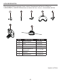
-
 1
1
-
 2
2
-
 3
3
-
 4
4
-
 5
5
-
 6
6
-
 7
7
-
 8
8
-
 9
9
-
 10
10
-
 11
11
-
 12
12
-
 13
13
-
 14
14
-
 15
15
-
 16
16
-
 17
17
-
 18
18
-
 19
19
-
 20
20
-
 21
21
-
 22
22
-
 23
23
-
 24
24
-
 25
25
-
 26
26
-
 27
27
-
 28
28
-
 29
29
-
 30
30
-
 31
31
-
 32
32
-
 33
33
-
 34
34
-
 35
35
-
 36
36
-
 37
37
-
 38
38
-
 39
39
-
 40
40
-
 41
41
-
 42
42
-
 43
43
-
 44
44
-
 45
45


Kobalt KST 180-06 Manual de usuario
- Categoría
- Herramientas eléctricas
- Tipo
- Manual de usuario
en otros idiomas
- English: Kobalt KST 180-06 User manual
Artículos relacionados
Otros documentos
-
Craftsman CMEST900 El manual del propietario
-
-
-
-
-
-
-
-
GE 97732LO Manual de usuario