Rockwell Automation 1606-XLE960 Manual de usuario
- Tipo
- Manual de usuario

1 EN Instruction Manual DC Power Supply
2
DE Bedienungsanleitung DC Stromversorgung
3 FR Manual d'instructions DC Alimentation d'Énergie
4 ES Manual de instrucciones DC Fuente De Alimentación
5 IT Manuale di Istruzione DC Gruppo di alimentazione
6 PT Manual de Instruções DC Fonte De Alimentação
1606-XLE960
Three-Phase Input
Read this first! English 1
Before operating this unit please read this manual thoroughly and retain this manual for future reference! This device may only be installed and put into operation by qualified personnel. If damage or
malfunction should occur during operation, immediately turn power off and send unit to the factory for inspection. The information presented in this document is believed to be accurate and reliable
and may change without notice. For any clarifications the English translation will be used.
Intended Use: This power supply
is designed for installation in an enclosure and is intended for the general use such as in industrial control, office, communication, and instrumentation equipment.
Do not use this power supply in aircrafts, trains and nuclear equipment where malfunction may cause severe personal injury or threaten human life.
WARNING
CAUTION
Risk of electrical shock, fire, personal injury or death.
(1) Do not use the power supply without proper grounding (Protective Earth).
(2) Turn power off before working on the device. Protect against inadvertent re-powering.
(3) Make sure that the wiring is correct by following all local and national codes.
(4) Do not modify or repair the unit. The unit does not contain serviceable parts.
(5) Do not open the unit as high voltages are present inside.
(6) Use caution to prevent any foreign objects from entering
into the housing.
(7) Do not use in wet locations or in areas where moisture or condensation can be expected.
(8) Do not touch during power-on, and immediately after power-off. Hot surface may cause burns.
Reduction of output current may be necessary when:
(1) Minimum installation clearance can not be met.
(2) Altitude is higher than 2000m.
(3) Device is used above 60°C ambient.
(4) Mounting orientation is other than output terminal located at the top and input at the
bottom.
(5) Airflow for convection cooling is obstructed.
Details for de-rating can be found in this manual and in the datasheet of the unit..
Vor Inbetriebnahme lesen! Deutsch 2
Bitte lesen Sie diese Warnungen und Hinweise sorgfältig durch bevor Sie das Gerät in Betrieb nehmen. Bewahren Sie die Anleitung zum Nachlesen auf. Das Gerät darf nur durch fachkundiges und
qualifiziertes Personal installiert werden. Bei Funktionsstörungen oder Beschädigungen schalten Sie sofort die Versorgungsspannung ab und senden das Gerät zur Überprüfung ins Werk. Das Gerät
beinhaltet keine Servicebauteile. Interne Sicherungen lösen nur bei Gerätedefekt aus. Die angegebenen Daten dienen allein der Produktbeschreibung und sind nicht als z
ugesicherte Eigenschaften
im Rechtssinne aufzufassen. Im Zweifelsfall gilt der englische Text
Bestimmungsgemäßer Gebrauch: Diese Stromversorgung ist für den Einbau in ein Gehäuse konzipiert und zur Verwendung für allgemeine elektronische Geräte, wie z.B. Industriesteuerungen,
Bürogeräte, Kommunikationsgeräte oder Messgeräte geeignet. Benutzen Sie diese Stromversorgung nicht in Steuerungsanlagen von Flugzeugen, Zügen oder nuklearen Einrichtungen, in denen eine
Funktionsstörung zu schweren Verletzungen führen oder Lebensgefahr bedeuten k
ann.
WARNUNG
VORSICHT
Missachtung nachfolgender Punkte kann einen elektrischen Schlag, Brände, schwere Unfälle oder Tod
zur Folge haben.
(1) Betreiben Sie die Stromversorgung nie ohne Schutzleiter.
(2) Schalten Sie die Eingangsspannung vor Installations-, Wartungs- oder Änderungsarbeiten ab und
sichern Sie diese gegen unbeabsichtigtes Wiedereinschalten.
(3) Sorgen Sie für eine ordnungsgemäße und fachgerechte Verdrahtung.
(4) Führen Sie keine Änderungen oder Reparaturversuche am Gerät durch.
(5) Gerät niemals öffnen. Im Innere
n befinden sich gefährliche Spannungen.
(6) Verhindern Sie das Eindringen von Fremdkörpern, wie z.B. Büroklammern und Metallteilen.
(7) Betreiben Sie das Gerät nicht in feuchter Umgebung oder in einer Umgebung, bei der mit Betauung
oder Kondensation zu rechnen ist.
(8) Gehäuse nicht während des Betriebes oder kurz nach dem Abschalten berühren. Heiße
Oberflächen können Verletzungen verursachen.
Rücknahme der Ausgangsleistung kann erforderlich sein:
(1) wenn die minimalen Einbauabstände nicht eingehalten werden können.
(2) bei Aufstellhöhen über 2000m.
(3) Betrieb bei Umgebungstemperaturen über 60°C.
(4) bei Einbaulagen abweichend von der Standardeinbaulage (Eingang unten, Ausgang
oben).
(5) bei behinderter Luftzirkulation.
Details zur Leistungsrücknahme befinden sich in dieser Betriebsanleitung oder im
Datenblatt des Gerätes.
siaçnarF !noisnet suos esim tnava eril A 3
Merci de lire ces instructions de montage et d'entretien avant de mettre l'alimentation sous tension. Conservez ce manuel qui vous sera toujours utile. Cette alimentation doit être installée par du
personnel qualifié et compétent. Le déclenchement du fusible interne traduit très probablement un défaut au niveau de l'appareil. Si un défaut quelconque apparaît en cours de fonctionnement,
débrancher au plus vite l'alimentation. Dans ce deux cas de figure, il convient de faire contrôler l'alimentation en usine! D'aut
res informations sont disponibles dans la documentation de mise en
service " Les données indiquées dans ce document servent uniquement à donner une description du produit et n'ont aucune valeur juridique. En cas de divergences, le texte anglais fait foi.
Utilisation: Cet appareil est conçu pour être installé dans une armoire et pour tous les équipements électroniques, tel que l'équipement industriel de commande, l'équipement de bureau, le matériel
de communication et les instruments de mesures. N'utilisez pa
s cet appareil pour l'équipement de commandes dans les avions, les trains et l'équipement atomique où un problème de
fonctionnement de l'alimentation pourrait causer des blessures graves ou menacer la vie humaine.
AVERTISSEMENT
ATTENTION
Prendre en compte les points suivants, afin d'éviter toute détérioration électrique, incendie, dommage
aux personnes ou mort.
(1) ne jamais faire fonctionner l'alimentation sans raccordement à la terre !
(2) débrancher l'installation avant toute intervention sur l'alimentation (ou démontage) et s'assurer qu'il
n'y a pas risque de redémarrage.
(3) s'assurer que le câblage a été fait selon les prescriptions
(4) ne pas effectuer de réparations ou modifications sur l'alimentation
(5) ne pas ouvrir l'appareil. Des tensions
importantes passent à l'intérieur.
(6) veiller à ce qu'aucun objet ne rentre en contact avec l'intérieur de l'alimentation (trombones, pièces
métalliques)
(7) ne pas faire fonctionner l'appareil dans un environnement humide ou à l'extérieur, non protégé. Ne
pas utiliser l'appareil dans un environnement où il peut y avoir de la condensation.
(8) ne pas toucher le carter pendant le fonctionnement ou après la mise sous tension. Surface chaude
risquant d’entraîner des blessures.
Des limitations de puissance de sortie peuvent apparaîtr
e si :
(1) les distances d'installation mini. ne peuvent être observées
(2) installation à une altitude > 2000 m
(3) pour des fonctionnements en charge et avec une température ambiante > 60°C
(4) pour des positions de montage différentes de la préconisation standard (entrée dessous,
sortie en haut)
(5) lorsque la circulation d'air est gênée

Lea primero! Español 4
Conserve este manual como referencia para futuras consultas. La fuente de alimentación solo puede ser instalada y puesta en funcionamiento por personal cualificado. Por favor lea detenidamente
este manual antes de conectar la fuente de alimentación. Cuando se funde un fusible interno, existe gran probabilidad de un fallo interno en el equipo.Si se produce un fallo o mal funcionamiento
durante la operación, desconecte inmediatamente la tensión de alimentación. En ambos casos, el equipo debe ser inspeccionado en
fábrica. La información presentada en este documento es
exacta y fiable en cuanto a la descripción del producto y puede cambiar sin aviso. En casa de duda, prevalece el texto inglés.
Uso apropiado: Este equipo ha sido diseñado para su instalación en un ambiente cerrado y ha sido concebido para uso general en instalaciones de control industrial, oficinas, comunicaciones y
equipos de instrumentación. No emplee este equipo en aeronaves, trenes e instalaciones atómicas, donde un mal funcionamiento de la fuente de alimentación puede ocas
ionar lesiones graves o
riesgo mortal.
ADVERTENCIA
ATENCIÓN
Riesgo de descarga eléctrica, incendio, accidente grave o muerte.
(1) No conectar nunca la unidad sin conexión de puesta a tierra.
(2) Desconectar la tensión de red antes de trabajar en la fuente de alimentación. Evite una posible
reconexión involuntaria.
(3) Asegurarse de que el cableado es correcto de acuerdo a los códigos locales y nacionales.
(4) No realizar ninguna modificación o reparación de la unidad.
(5) No abrir nunca la unidad. En el interior existe riesgo de altas tensiones.
(6) Evitar la introducción en la carcasa de
objetos extraños.
(7) No usar el equipo en ambientes húmedos. No operar el equipo en ambientes donde se espere la
formación de rocío o condensación.
(8) No tocar durante el funcionamiento ni inmediatamente después del apagado. El calor de la
superficie puede causar quemaduras graves
La deriva en la tensión de salida se produce:
(1) cuando no pueden mantenerse las distancias mínimas de montaje.
(2) en caso de que el montaje se realice en altitudes superiores a los 2000 m.
(3) en caso de funcionamiento a plena
carga y temperaturas ambientales superiores a
60ºC.
(4) En caso de posiciones de montaje diferentes a la posición de montaje estándar
(terminales de entrada abajo y terminales de salida arriba).
(5) en caso de que la circulación de aire para la refrigeración por conducción esté
obstruida.
Puede encontrar más detalles del caso de deriva en este manual.
Leggere prima questa parte! Italiano 5
Prima di collegare il sistema di alimentazione elettrica si prega di leggere attentamente le seguenti avvertenze. Conservare le istruzioni per la consultazione futura. Il sistema di alimentazione elettrica
deve essere installato solo da personale competente e qualificato. In caso di intervento del fusibile interno, molto probabilmente l'apparecchio è guasto. Se durante il funzionamento si verificano
anomalie o guasti, scollegare immediatamente la tensione di alimentazione. In entrambi i casi è necessario f
ar controllare l'apparecchio dal produttore! I dati sono indicati solo a scopo descrittivo del
prodotto e non vanno considerati come caratteristiche garantite dell'apparecchio.In caso di differenze o problemi è valido il testo inglese
Uso previsto: Questo apparecchio è previsto per il montaggio in un rack per moduli elettronici, ad esempio per controllori industriali, apparecchiature per ufficio, unità di comunicazione o apparecchi
di misura. Non utilizzare l'apparecchio in impianti di controllo di aerei, di treni o di im
pianti nucleari in cui il suo eventuale guasto può comportare gravi lesioni o la morte di persone.
AVVERTENZA
ATTENZIONE
Il mancato rispetto delle seguenti norme può provocare folgorazione elettrica, incendi, gravi incidenti e
perfino la morte.
(1) Non far funzionare in nessun caso il sistema di alimentazione elettrica senza conduttore di
protezione!
(2) Prima di eseguire interventi di installazione, di manutenzione o di modifica scollegare la tensione di
rete ed adottare tutti i provvedimenti necessari per impedirne il ricollegamento non intenzionale.
(3) Assicurare un cablaggio regolare e corretto.
(4) Non
tentare di modificare o di riparare da soli l'apparecchio.
(5) Non aprire l'apparecchio. Al suo interno sono applicate tensioni elettriche pericolose.
(6) Impedire la penetrazione di corpi estranei nell'apparecchio, ad esempio fermagli o altri oggetti
metallici.
(7) Non far funzionare l'apparecchio in un ambiente umido. Non far funzionare l'apparecchio in un
ambiente soggetto alla formazione di condensa o di rugiada.
(8) Non toccare quando acceso e subito dopo lo spegnimento. La superficie calda può causare
scottature.
È necessari
o ridurre la potenza di uscita se:
(1) non è possibile rispettare le distanze minime di montaggio;
(2) l'apparecchio viene installato in un luogo di altitudine maggiore di 2000 m;
(3) il funzionamento è a pieno carico a temperatura ambiente maggiore di 60 °C;
(4) la posizione di montaggio differisce da quella standard (ingresso in basso, uscita in
alto);
(5) è ostacolata la libera circolazione dell'aria.
Ulteriori informazioni sono riportate in questo manuale.
Leia primeiro! Portuguès 6
Recomendamos a leitura cuidadosa das seguintes advertências e observações, antes de colocar em funcionamento a fonte de alimentação. Guarde as Instruções para futura consulta, em casos de
dúvida. A fonte de alimentação deverá ser instalada apenas por profissionais da área, tecnicamente qualificados. Se o fusível interno se fundir, é grande a possibilidade de existir um defeito no
aparelho. Se por acaso, durante a utilização ocorrer algum defeito de funcionamento ou dano, desligue imediatamente a tensão de alimentação. Em ambo
s os casos, será necessária uma
verificação na Fábrica! Os dados mencionados têm como finalidade somente a descrição do produto, e não devem ser interpretados como propriedades garantidas no sentido jurídico. Em caso de
duvidas aplica-se o texto em inglês.
Utilize: Apenas para o fim pré-estabelecido. Este aparelho foi concebido para ser montado dentro de invólucros, caixas ou armários para aparelhos eletrônicos em geral, como, por exemplo,
comandos de instalações industriais, aparelhos para escritórios, aparelhos de c
omunicação ou instrumentos de medida e quadros eléctricos. Não utilize este aparelho em sistemas de comando de
aviões, de comboios ou em instalações movidas por energia nuclear, nos quais um defeito de funcionamento poderá causar danos graves ou significar risco de morte.
ATENÇÃO
CUIDADO
A não observância ou o incumprimento dos pontos a seguir mencionados, poderá causar uma
descarga elétrica, incêndios, acidentes graves ou morte.
(1) Não use a fonte de alimentação sem o condutor de proteção terra!
(2) Antes de trabalhos de instalação, manutenção ou modificação, desligue a tensão de alimentação,
protegendo-a contra uma nova ligação involuntária.
(3) As ligações devem ser efectuadas apenas por profissionais competentes.
(4) Não efectue nenhuma modificação ou tentativa de reparação no aparelho. Quando ne
cessário
contacte o seu distribuidor.
(5) Não abra o aparelho mesmo quando desligado. No seu interior existem condensadores que podem
estar carregados electricamente.
(6) Proteger a fonte de alimentação contra a introdução inadvertida de corpos metálicos, como por ex.,
clipes ou outras peças de metal.
(7) Não usar o aparelho em ambientes húmidos. Não usar o aparelho em ambientes propensos a
condensações.
(8) Não tocar enquanto estiver em funcionamento, nem após a desligar. A superficie poderá estar
quente e p
rovocar lesões.
Será necessário reduzir a potência de saída nos seguintes casos:
(1) Quando não forem observadas as distâncias mínimas de montagem.
(2) Quando instaladas a altitudes superiores a 2000m.
(3) Existencia de temperatura ambiente superior a 60ºC, em plena carga do aparelho.
(4) Montagem invertida do aparelho (Entrada em baixo, saída em cima).
(5) Montagem em ambiente sem ventilação.
No presente manual de funcionamento encontram-se ainda outras informações.
Rockwell Automation
CH-5001 Aarau, Switzerland
Fax +41 62 837 2202
© 2009 by
Allen-Bradley Company, LCC
Industrial Components Business
1201 South Second Street
Milwaukee, WI 53204-2496 USA
Phone 440 646 5800

1606-XLE960 Instruction Manual for Semi-regulated Power Supplies
1606-XLE960 Bedienungsanleitung für teilgeregelte Stromversorgungen
Product Description; Semi-Regulated 3-Phase Power Supply
These power supplies include a new and innovative concept for generating a DC voltage from a
three-phase input. A semi-regulated resonant converter enables a very compact design, maximum
efficiency and extremely competitive pricing, with only a small compromise in the output voltage
regulation, output ripple and hold-up time.
Weighing just 1.4 kg, the device provides 960 watts of continuous output power and an additional
25% power reserve for dynamic loads. The light-weight and compact dimensions facilitate
straightforward mounting on DIN-rail.
Principal uses are applications involving supplies to motors, valves and other load circuits with a
high power consumption, where an accurate output voltage regulation (standard on switch mode
power supplies) is not required.
Gerätebeschreibung; Teilgeregelte 3-Phasen Stromversorgung
Diese Stromversorgungen verwenden ein neues und innovatives Konzept zur Erzeugung einer
DC-Spannung bei Drehstromeingang. Ein teilgeregelter Resonanzwandler ermöglicht kleinste
Baugröße, höchsten
Wirkungsgrad und äußerst attraktive Kosten zugunsten kleiner
Kompromisse in der Regelung, Ausgangswelligkeit und Pufferzeit. Das Leichtgewicht mit nur
1,4kg stellt 960W Dauerausgangsleistung und zusätzlich 25% Leistungsreserve für dynamische
Verbraucher zur Verfügung. Durch das geringe Gewicht und die kleinen Abmessungen ist eine
einfache Montage auf der DIN-Schiene problemlos möglich. Einsatzschwerpunkte sind
Anwendungen zum Versorgen von Motoren, Ventilen und Laststromkreisen, die einen hohen
Strombedarf haben und für die eine genaue Regel
ung – wie es bei vollgeregelten
Schaltnetzteilen üblich ist – nicht erforderlich ist.
1) At nominal load
2) 50 Ohm measurement, bandwidth 20MHz. The ripple and noise voltage mostly consist of a mains
ripple with 300Hz (50Hz mains) or 360Hz (60Hz mains). The ripple and noise voltage can be
reduced by the utilization of external capacitors.
3) No electrolytic bulk-capacitors utilized on the input. Virtually no input inrush current surge.
4)
Depth without DIN-rail
5) EN 61000-3-2 is the European standard for harmonic current emission (PFC)
6) See description and details on next page
7) Output voltage is fixed. No adjustments possible
8) All parameters are specified at nominal input voltage, nominal output current, 25°C ambient and
after a 5 minutes run-in time unless otherwise noted.
9) Do not energize while condensation is present.
10) As soon as the input is turned off, the output capacitor will be discharged and the voltage drops.
The number in the parenthesis is the output voltage after 3ms and nominal load.
1)
bei Nennlast
2) 50 Ohm Messung, Bandbreite 20MHz. Die Ausgangswelligkeit besteht hauptsächlich aus
einem Netzrippel mit 300Hz (50Hz Netz) oder 360Hz (60Hz Netz). Die Ausgangswelligkeit
kann durch die Verwendung von externen Kondensatoren verringert werden.
3) Dank elkolosem Eingang kein Einschaltspitzenstrom vorhanden.
4)
Tiefe ohne DIN-Schiene
5) Die EN 61000-3-2 ist der EU Standard zur Festlegung der zulässigen Oberwellenströme die
ein Gerät erzeugen darf (PFC).
6) Beachte Beschreibung und Details der nächsten Seite.
7) Ausgangsspannung fest eingestellt. Keine Verstellung möglich.
8) Alle Werte gelten bei Nenn- Eingangsspannung, Nenn- Ausgangsstrom, 25°C Umgebungs-
temperatur und nach einer Aufwärmzeit von 5 Minuten wenn nichts anderes angegeben ist.
9) Nicht betreiben, solange das Gerät Kondensation aufweist.
10)
Nach Abschaltung des Eingangs werden die Ausgangskondensatoren entladen und die
Spannung sinkt ab. Der Wert in Klammer gibt die Spannung nach 3ms und Nennlast an.
Installation
Use DIN-rails according to EN 60715 or EN 50022 with a height of 7.5 or 15mm. Mounting
orientation must be output terminals on top and input terminals on the bottom. For other orientations
see datasheet. Do not obstruct air flow as the unit is convection cooled. Ventilation grid must be kept
free of any obstructions. The following installation clearances must be kept when power supplies are
permanently fully loaded:
Left / right: 5mm (15mm in case the adjacent device is a heat source)
40mm on top, 20mm on the bottom
Installation
Geeignet für DIN-Schienen entsprechend EN 60715 oder EN 50022 mit einer Höhe von 7,5
oder 15mm. Der Einbau hat so zu erfolgen, dass sich die Eingangsklemmen unten, und die
Ausgangsklemmen oben befinden. Für andere Einbaulagen siehe Datenblatt. Luftzirkulation
nicht behindern! Das Gerät ist für Konvektionskühlung ausgelegt. Es ist für ungehinderte
Luftzirkulation zu sorgen. Folgende Einbauabstände sind bei dauerhafter Volllast einzuhalten:
Links / rechts: 5mm (15mm bei benachbarten Wärmequellen)
Oben: 40mm, unten 20mm
Input Fuses
No internal input fuse. The unit is tested and approved for branch circuits up to 16A (U.S.A 15A).
External protection is only required, if the supplying branch has an ampacity greater than this. In
some countries local regulations might apply. Check also local codes and local requirements. If an
external fuse is necessary or utilized, minimum requirements need to be considered. To avoid
nuisance tripping of the circuit breaker, a minimum value of 3A C-Characteristic or 6A B-
Characteristic should be used.
Sicherungen am Eingang
Diese Geräte besitzen keine interne Eingangssicherung. Diese Geräte sind geprüft und
zugelassen zum Anschluss an Stromkreise bis max. 16A (U.S.A. 15A). Ein zusätzlicher
externer Schutz ist nur erforderlich wenn der Speisestromkreis mit einem höheren Wert
abgesichert ist oder nationale Richtlinien es vorschreiben. Falls ein externes Schutzelement
verwendet wird, soll dieses nicht kleiner als 3A (C- Charakteristik) oder 6A (B- Charakteristik)
sein, um ein fehlerhaftes Auslösen zu vermeiden.
EMC Electromagnetic Compatibility
These devices are suitable for applications in industrial environment as well as in residential,
commercial and light industry environment without any restrictions. These devices comply with FCC
Part 15 rules.
CE mark is in conformance with EMC guideline 89/336/EC, 93/68/EC and 2004/108/EC and the low-
voltage directives (LVD) 73/23/EC, 93/68/EC, 2006/95/EC.
EMC Immunity: EN 61000-6-1, EN 61000-6-2; EMC Emission EN 61000-3-2, EN 61000-3-3, EN
61000-6-3, EN 61000-6-4, FCC Part 15
EMV Elektromagnetische Verträglichkeit
Diese Geräte erfüllen die Anforderungen für Anwendungen in industrieller Umgebung als auch
für den Wohn-, Geschäfts- und Gewerbebereich ohne Einschränkungen. Die Geräte erfüllen
auch die Anforderungen der FCC Teil 15. Das CE Zeichen ist angebracht und erklärt die
Erfüllung der EMV Richtlinien 89/336/EG, 93/68/EG und 2004/108/EG wie auch die
Niederspannungsrichtlinien 73/23/EG, 93/68/EG, 2006/95/EG.
Störfestigkeit: EN 61000-6-1, EN 61000-6-2; Störaussendung: EN 61000-3-2, EN 61000-3-3,
EN 61000-6-3
, EN 61000-6-4, FCC Part 15
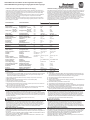
Technical Data
8)
Technische Daten
8)
1606-XLE960DX-3N 1606-XLE960MX-3N
Output voltage Ausgangsspannung DC 24V DC 48V
Factory setting
7)
Werkseinstellung
7)
typ. 24.1V 48.0V
Output current continuous Ausgangsstrom dauernd nom. 40A 20A
up to 15s
6)
bis zu 15s
6)
nom. 50A 25A
Output power continuous Ausgangsleistung dauernd nom. 960W 960W
up to 15s
6)
bis zu 15s
6)
nom. 1200W 1200W
Output ripple
2)
Ausgangswelligkeit
2)
max. 1500mVpp 2500mVpp
AC Input voltage AC Eingangsspannung nom. 3AC 480V ±15% 3AC 480V ±15%
2-Phase Operation Betrieb an nur 2 Phasen no / nein no / nein
AC Input current / phase
1)
AC Eingangsstrom / Phase
1)
nom. 1.4A 1.4A
Hold-up time
10)
Pufferzeit
10)
typ. 3ms (19V) 3ms (41V)
Power factor
1)
Leistungsfaktor.
1)
typ. 0.93 0.93
EN 61000-3-2
5)
EN 61000-3-2
5)
Yes / ja yes / ja
Inrush current
3)
Einschaltspitzenstrom
3)
typ. 4A 4A
Over-voltage protection, OVP
6)
Überspannungsschutz, OVP
6)
max. 29.9V 57.2V
Efficiency
1)
Wirkungsgrad
1)
typ. 95.5% 96.0%
Losses
1)
gnutsieltsulreV
1)
typ. 45.2W 40.0W
Operational temperature range Betriebstemperaturbereich nom. -25°C to +70°C -25°C to +70°C
Output derating Leistungsrücknahme nom. 24W/°C, >60°C 24W/°C, >60°C
Storage temperature Lagertemperaturbereich nom. -40°C to +85° C -40°C to +85° C
Humidity
9)
ethcueF
9)
IEC 60068-2-30
< 95% r .H. < 95% r .H.
negniwhcS noitarbiV
IEC 60068-2-6
1g 1g
nekcohcS kcohS
IEC 60068-2-27
15g 6ms, 10g 11ms 15g 6ms, 10g 11ms
Degree of pollution Verschmutzungsgrad
EN 50178
2 2
Overload, short-circuit proof Überlast, Kurzschlussschutz yes / ja yes / ja
Degree of protection Schutzart IP 20, EN/IEC 60529 IP 20, EN/IEC 60529
Class of protection Schutzklasse I I
Over-voltage category Überspannungskategorie III, EN 50178 III, EN 50178
Over-temperature protection Übertemperaturschutz yes / ja yes / ja
Penetration protection Fremdkörper Eindringschutz >3.5mm >3.5mm
Parallel use Betrieb in Parallelschaltung no / nein no / nein
gnutlahcsneireS ni beirteB esu laireS yes / ja yes / ja
Dimensions (wxhxd)
4)
Abmessungen (BxHxT)
4)
nom. 96x124x157mm 96x124x157mm
thciweG thgieW max. 1400g / 3.09lb 1400g / 3.09lb

1606-XLE960 Instruction Manual for Semi-regulated Power Supplies
1606-XLE960 Bedienungsanleitung für teilgeregelte Stromversorgungen
Terminals and Wiring
Do not use the unit without PE (Ground) connection! Use appropriate copper cables that are
designed for a minimum operating temperatures of 60°C (for ambient up to 45°C) and 75°C (for
ambient up to 60°C). Follow national installation codes and regulations! Ensure that all strands of a
stranded wire enter the terminal connection! Up to two stranded wires with the same cross section
are permitted in one connection point (except PE wire). Ferrules are allowed, but not required.
Input Output
Solid wire 0.5-6mm
2
0.5-16mm
2
Stranded wire 0.5-4mm
2
0.5-10mm
2
American wire gauge 20-10 AWG 22-8 AWG
Wire stripping length 7mm / 0.28inch 12mm / 0.5inch
Recommended tightening torque 0.8Nm / 7lb.inch 1.2Nm / 10.6lb.inc
Anschlussklemmen und Verdrahtung
Betreiben Sie das Gerät nie ohne Schutzleiter. Verwenden Sie geeignete Kupferkabel, die
mindestens für 60°C bei einer Umgebungstemperatur bis zu 45°C und 75°C bei einer
Umgebungstemperatur bis zu 60°C zugelassen sind. Beachten Sie nationale Bestimmungen
und Installationsvorschriften! Stellen Sie sicher, dass keine einzelnen Drähte von Litzen
abstehen. Bis zu zwei Leiter mit gleichem Querschnitt sind in einem Anschlusspunkt zulässig
(außer für den Schutzleiter). Aderendhülsen sind erlaubt, aber nicht erforderlich.
gnagsuA gnagniE
Starrdraht 0.5-6mm
2
0.5-16mm
2
Litze 0.5-4mm
2
0.5-10mm
2
AWG 20-10 AWG 22-8 AWG
Abisolierlänge 7mm / 0.28inch 12mm / 0.5inch
Empfohlenes Anzugsmoment 0.8Nm / 7lb.inch 1.2Nm / 10.6lb.inch
Indicators and Reset Button (see Fig. 6)
DC-ok LED (green): Indicates a normal operation. The LED is on if the output voltage is higher
than 90% of its nominal value.
Warning LED (yellow):
- A steady-state light indicates an output current higher than the nominal current
and that the internal shutdown timer is running.
- A double flash indicates a phase-loss or too low / too high input voltage.
- A fast flash warns of an impending temperature shut-down.
Shut-down LED (red) and reset button: The red lamp flashes when the device has shut down.
Pressing the reset button initiates a restart. If the fault has been cleared, the device will operate
normally.
Anzeigelampen und “Reset“ Taster (siehe Bild 6)
“DC-ok” LED (grün): Zeigt einen fehlerfreien Betrieb und eine Ausgangsspannung größer
90% der Nennspannung an.
”Warning” LED (gelb):
- Dauerleuchten zeigt an, dass der Ausgangsstrom höher als der Nennstrom
ist und dass der interne Abschalt-Timer gestartet hat.
- Doppelblinken meldet Phasenausfall oder zu geringe / zu hohe Eingangsspannung.
- Ein schnelles Blinken kündigt eine mögliche Temperaturabschaltung an.
”Shut-down” LED (rot) und “Reset“ Taster: Die rote LED blinkt, wenn das Gerät
abgeschaltet hat. Das Drücken des Reset Tasters verursacht einen Startversuch. Ist
zwischenzeitlich der Fehler beseitigt worden, läuft das Gerät im Normalbetrieb weiter.
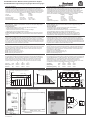
Input Voltage Range (see Fig. 1)
Changes of the input voltage will provide a regulated output within certain limits. The output voltage
only changes proportionally to the input voltage under extreme under-voltages or over-voltages
conditions. The yellow LED reports an input voltage problem if the input voltage exceeds a window
of ±15%. The maximum increase of the output voltage is limited to the OVP level values (see table
on the page befre). The OVP level will be kept regulated for 2s. If this time
has elapsed, the power
supply shuts-down and reports “Shut-down” by the red LED.
Eingangsspannungsbereich
(siehe Bild 1)
Innerhalb gewisser Grenzen werden die Änderungen der Eingangsspannung vollständig
ausgeregelt. Erst bei extremen Unter- bzw. Überspannungen beginnt die Ausgangsspannung
sich proportional zur Eingansspannung zu ändern. Außerhalb des ±15% Fensters meldet die
gelbe LED ein Problem mit der Eingangsspannung. Der Anstieg der Ausgangsspannung ist auf
den OVP Wert (siehe Tabelle auf der vorangegangenen Seite
) begrenzt. Der OVP Wert wird für
2s gehalten, danach schaltet das Gerät ab und meldet „Shut-down“.
Output- and Overload Characteristic (see Fig. 2)
The power supply responds with an automatic shut-down if the nominal output current is exceeded
for a certain period of time. Pressing the reset button or cycling the input power (10s required)
initiates an attempt to start. If the fault has been cleared, the device will operate normally. The
characteristics can be found in figure 3.
Zone A: 25% extra output power for typ. 15s
Zone B: 100% higher output current for typ. 5s
Zone C: Quick-acting shut-down after 0.1s
Ausgangs- und Überlastverhalten
(siehe Bild 2)
Wird der Nennstrom für eine bestimmte Zeit überschritten, schaltet das Gerät automatisch ab.
Ein Drücken des Reset Tasters oder ein Neustart des Gerätes (Wartezeit etwa 10s) erzeugt
einen Startversuch. Ist der Fehler behoben, läuft das Gerät wieder im Normalbetrieb weiter.
Das Verhalten ist im Bild 3 gezeigt.
Zone A: 25% mehr Ausgangsleistung für typ. 15s
Zone B: 100% höherer Ausgangsstrom für typ. 5s
Zone C: Schnellabschaltung nach 0,1s
Dielectric Strength (see Fig. 7)
The output voltage is floating and separated from the input according to SELV (IEC/EN 60950-1)
and PELV (EN 60204-1, EN 50178; IEC 62103, IEC 60364-4-41) requirements. Type and factory
tests are conducted by the manufacturer. Field tests may be conducted in the field using the
appropriate test equipment which applies the voltage with a slow ramp (2s up and 2s down).
Connect all phase-terminals together as well as all output poles before the test is conducted.
A B C
Type Test (60s) 2500Vac 3000Vac 500Vac
Factory Test (5s
) 2500Vac 2500Vac 500Vac
Field Test (5s) 2000Vac 2000Vac 500Vac
Isolationsfestigkeit (siehe Bild 7)
Die Ausgangsspannung hat keinen Bezug zur Erde oder Schutzleiter und ist zum Eingang nach
den SELV (IEC/EN 60950-1) und PELV (EN 60204-1, EN 50178, IEC 62103, IEC 60364-4-41)
Standards getrennt. Typ- und Stückprüfungen werden beim Hersteller durchgeführt.
Wiederholungsprüfungen dürfen mittels geeigneten Prüfgenerators mit langsam (2s)
ansteigenden und abfallenden Spannungsrampen in der Anwendung erfolgen. Vor den Tests
sind alle Phasen wi
e auch alle Ausgangspole miteinander zu verbinden.
C B A
Typprüfung (60s) 2500Vac 3000Vac 500Vac
Stückprüfung (5s) 2500Vac 2500Vac 500Vac
Wiederholungsprüfung (5s) 2000Vac 2000Vac 500Vac
Fig. 1 / Bild 1
Input voltage range / Eingangsspannungsbereich
Fig. 2 / Bild 2
Overload behaviour / Überlastverhalten
Fig. 3 / Bild 3
Functional Diagram / Funktionsschaltbild
24V
20V
26V
22V
504456 576Vac384
V
OUT
V
IN
480
28V
528 552432408360
P
OUT
> 48W (5%)
56V
52V
48V
44V
40V
48V
24V
P
OUT
= 0W
V
OUT
40 50 115A80
I
OUT
0
C
0.1s
B
5s
A
15s
24V:
48V: 20 25 58A400
+
-
Active
Transient
Blocker
Input
Filter
Input
Rectifier
Reset
Output
Voltage
Monitor
Over-
Voltage
Protection
Output
Power
Manager
Temp.
Shut-
down
Input
Voltage
Monitor
L3
L2
L1
Semi-
regulated
Power
Converter
Output
Filter
DC-ok
lamp
Shut
down
Warning
lamp
Fig. 4 / Bild 4
Dimensions / Abmessungen
Fig. 5 / Bild 5
Dimensions / Abmessungen
Fig. 6 / Bild 6
Indicators / Anzeigeelemente
Fig. 7 / Bild 7
Isolation / Isolation
A
C
B
L1
Input
Earth
Output
-
+
L3
L2
10000044637 (version 00)
PU-353.010.39-10B
Transcripción de documentos
1 2 3 4 5 6 EN DE FR ES IT PT Instruction Manual Bedienungsanleitung Manual d'instructions Manual de instrucciones Manuale di Istruzione Manual de Instruções DC Power Supply DC Stromversorgung DC Alimentation d'Énergie DC Fuente De Alimentación DC Gruppo di alimentazione DC Fonte De Alimentação Read this first! 1606-XLE960 Three-Phase Input English 1 Before operating this unit please read this manual thoroughly and retain this manual for future reference! This device may only be installed and put into operation by qualified personnel. If damage or malfunction should occur during operation, immediately turn power off and send unit to the factory for inspection. The information presented in this document is believed to be accurate and reliable and may change without notice. For any clarifications the English translation will be used. Intended Use: This power supply is designed for installation in an enclosure and is intended for the general use such as in industrial control, office, communication, and instrumentation equipment. Do not use this power supply in aircrafts, trains and nuclear equipment where malfunction may cause severe personal injury or threaten human life. WARNING Risk of electrical shock, fire, personal injury or death. (1) Do not use the power supply without proper grounding (Protective Earth). (2) Turn power off before working on the device. Protect against inadvertent re-powering. (3) Make sure that the wiring is correct by following all local and national codes. (4) Do not modify or repair the unit. The unit does not contain serviceable parts. (5) Do not open the unit as high voltages are present inside. (6) Use caution to prevent any foreign objects from entering into the housing. (7) Do not use in wet locations or in areas where moisture or condensation can be expected. (8) Do not touch during power-on, and immediately after power-off. Hot surface may cause burns. CAUTION Reduction of output current may be necessary when: (1) Minimum installation clearance can not be met. (2) Altitude is higher than 2000m. (3) Device is used above 60°C ambient. (4) Mounting orientation is other than output terminal located at the top and input at the bottom. (5) Airflow for convection cooling is obstructed. Details for de-rating can be found in this manual and in the datasheet of the unit.. Vor Inbetriebnahme lesen! Deutsch 2 Bitte lesen Sie diese Warnungen und Hinweise sorgfältig durch bevor Sie das Gerät in Betrieb nehmen. Bewahren Sie die Anleitung zum Nachlesen auf. Das Gerät darf nur durch fachkundiges und qualifiziertes Personal installiert werden. Bei Funktionsstörungen oder Beschädigungen schalten Sie sofort die Versorgungsspannung ab und senden das Gerät zur Überprüfung ins Werk. Das Gerät beinhaltet keine Servicebauteile. Interne Sicherungen lösen nur bei Gerätedefekt aus. Die angegebenen Daten dienen allein der Produktbeschreibung und sind nicht als zugesicherte Eigenschaften im Rechtssinne aufzufassen. Im Zweifelsfall gilt der englische Text Bestimmungsgemäßer Gebrauch: Diese Stromversorgung ist für den Einbau in ein Gehäuse konzipiert und zur Verwendung für allgemeine elektronische Geräte, wie z.B. Industriesteuerungen, Bürogeräte, Kommunikationsgeräte oder Messgeräte geeignet. Benutzen Sie diese Stromversorgung nicht in Steuerungsanlagen von Flugzeugen, Zügen oder nuklearen Einrichtungen, in denen eine Funktionsstörung zu schweren Verletzungen führen oder Lebensgefahr bedeuten kann. WARNUNG Missachtung nachfolgender Punkte kann einen elektrischen Schlag, Brände, schwere Unfälle oder Tod zur Folge haben. (1) Betreiben Sie die Stromversorgung nie ohne Schutzleiter. (2) Schalten Sie die Eingangsspannung vor Installations-, Wartungs- oder Änderungsarbeiten ab und sichern Sie diese gegen unbeabsichtigtes Wiedereinschalten. (3) Sorgen Sie für eine ordnungsgemäße und fachgerechte Verdrahtung. (4) Führen Sie keine Änderungen oder Reparaturversuche am Gerät durch. (5) Gerät niemals öffnen. Im Inneren befinden sich gefährliche Spannungen. (6) Verhindern Sie das Eindringen von Fremdkörpern, wie z.B. Büroklammern und Metallteilen. (7) Betreiben Sie das Gerät nicht in feuchter Umgebung oder in einer Umgebung, bei der mit Betauung oder Kondensation zu rechnen ist. (8) Gehäuse nicht während des Betriebes oder kurz nach dem Abschalten berühren. Heiße Oberflächen können Verletzungen verursachen. VORSICHT Rücknahme der Ausgangsleistung kann erforderlich sein: (1) wenn die minimalen Einbauabstände nicht eingehalten werden können. (2) bei Aufstellhöhen über 2000m. (3) Betrieb bei Umgebungstemperaturen über 60°C. (4) bei Einbaulagen abweichend von der Standardeinbaulage (Eingang unten, Ausgang oben). (5) bei behinderter Luftzirkulation. Details zur Leistungsrücknahme befinden sich in dieser Betriebsanleitung oder im Datenblatt des Gerätes. A lire avant mise sous tension! Français 3 Merci de lire ces instructions de montage et d'entretien avant de mettre l'alimentation sous tension. Conservez ce manuel qui vous sera toujours utile. Cette alimentation doit être installée par du personnel qualifié et compétent. Le déclenchement du fusible interne traduit très probablement un défaut au niveau de l'appareil. Si un défaut quelconque apparaît en cours de fonctionnement, débrancher au plus vite l'alimentation. Dans ce deux cas de figure, il convient de faire contrôler l'alimentation en usine! D'autres informations sont disponibles dans la documentation de mise en service " Les données indiquées dans ce document servent uniquement à donner une description du produit et n'ont aucune valeur juridique. En cas de divergences, le texte anglais fait foi. Utilisation: Cet appareil est conçu pour être installé dans une armoire et pour tous les équipements électroniques, tel que l'équipement industriel de commande, l'équipement de bureau, le matériel de communication et les instruments de mesures. N'utilisez pas cet appareil pour l'équipement de commandes dans les avions, les trains et l'équipement atomique où un problème de fonctionnement de l'alimentation pourrait causer des blessures graves ou menacer la vie humaine. AVERTISSEMENT Prendre en compte les points suivants, afin d'éviter toute détérioration électrique, incendie, dommage aux personnes ou mort. (1) ne jamais faire fonctionner l'alimentation sans raccordement à la terre ! (2) débrancher l'installation avant toute intervention sur l'alimentation (ou démontage) et s'assurer qu'il n'y a pas risque de redémarrage. (3) s'assurer que le câblage a été fait selon les prescriptions (4) ne pas effectuer de réparations ou modifications sur l'alimentation (5) ne pas ouvrir l'appareil. Des tensions importantes passent à l'intérieur. (6) veiller à ce qu'aucun objet ne rentre en contact avec l'intérieur de l'alimentation (trombones, pièces métalliques) (7) ne pas faire fonctionner l'appareil dans un environnement humide ou à l'extérieur, non protégé. Ne pas utiliser l'appareil dans un environnement où il peut y avoir de la condensation. (8) ne pas toucher le carter pendant le fonctionnement ou après la mise sous tension. Surface chaude risquant d’entraîner des blessures. ATTENTION Des limitations de puissance de sortie peuvent apparaître si : (1) les distances d'installation mini. ne peuvent être observées (2) installation à une altitude > 2000 m (3) pour des fonctionnements en charge et avec une température ambiante > 60°C (4) pour des positions de montage différentes de la préconisation standard (entrée dessous, sortie en haut) (5) lorsque la circulation d'air est gênée Lea primero! Español 4 Conserve este manual como referencia para futuras consultas. La fuente de alimentación solo puede ser instalada y puesta en funcionamiento por personal cualificado. Por favor lea detenidamente este manual antes de conectar la fuente de alimentación. Cuando se funde un fusible interno, existe gran probabilidad de un fallo interno en el equipo.Si se produce un fallo o mal funcionamiento durante la operación, desconecte inmediatamente la tensión de alimentación. En ambos casos, el equipo debe ser inspeccionado en fábrica. La información presentada en este documento es exacta y fiable en cuanto a la descripción del producto y puede cambiar sin aviso. En casa de duda, prevalece el texto inglés. Uso apropiado: Este equipo ha sido diseñado para su instalación en un ambiente cerrado y ha sido concebido para uso general en instalaciones de control industrial, oficinas, comunicaciones y equipos de instrumentación. No emplee este equipo en aeronaves, trenes e instalaciones atómicas, donde un mal funcionamiento de la fuente de alimentación puede ocasionar lesiones graves o riesgo mortal. ADVERTENCIA Riesgo de descarga eléctrica, incendio, accidente grave o muerte. (1) No conectar nunca la unidad sin conexión de puesta a tierra. (2) Desconectar la tensión de red antes de trabajar en la fuente de alimentación. Evite una posible reconexión involuntaria. (3) Asegurarse de que el cableado es correcto de acuerdo a los códigos locales y nacionales. (4) No realizar ninguna modificación o reparación de la unidad. (5) No abrir nunca la unidad. En el interior existe riesgo de altas tensiones. (6) Evitar la introducción en la carcasa de objetos extraños. (7) No usar el equipo en ambientes húmedos. No operar el equipo en ambientes donde se espere la formación de rocío o condensación. (8) No tocar durante el funcionamiento ni inmediatamente después del apagado. El calor de la superficie puede causar quemaduras graves ATENCIÓN La deriva en la tensión de salida se produce: (1) cuando no pueden mantenerse las distancias mínimas de montaje. (2) en caso de que el montaje se realice en altitudes superiores a los 2000 m. (3) en caso de funcionamiento a plena carga y temperaturas ambientales superiores a 60ºC. (4) En caso de posiciones de montaje diferentes a la posición de montaje estándar (terminales de entrada abajo y terminales de salida arriba). (5) en caso de que la circulación de aire para la refrigeración por conducción esté obstruida. Puede encontrar más detalles del caso de deriva en este manual. Leggere prima questa parte! Italiano 5 Prima di collegare il sistema di alimentazione elettrica si prega di leggere attentamente le seguenti avvertenze. Conservare le istruzioni per la consultazione futura. Il sistema di alimentazione elettrica deve essere installato solo da personale competente e qualificato. In caso di intervento del fusibile interno, molto probabilmente l'apparecchio è guasto. Se durante il funzionamento si verificano anomalie o guasti, scollegare immediatamente la tensione di alimentazione. In entrambi i casi è necessario far controllare l'apparecchio dal produttore! I dati sono indicati solo a scopo descrittivo del prodotto e non vanno considerati come caratteristiche garantite dell'apparecchio.In caso di differenze o problemi è valido il testo inglese Uso previsto: Questo apparecchio è previsto per il montaggio in un rack per moduli elettronici, ad esempio per controllori industriali, apparecchiature per ufficio, unità di comunicazione o apparecchi di misura. Non utilizzare l'apparecchio in impianti di controllo di aerei, di treni o di impianti nucleari in cui il suo eventuale guasto può comportare gravi lesioni o la morte di persone. AVVERTENZA Il mancato rispetto delle seguenti norme può provocare folgorazione elettrica, incendi, gravi incidenti e perfino la morte. (1) Non far funzionare in nessun caso il sistema di alimentazione elettrica senza conduttore di protezione! (2) Prima di eseguire interventi di installazione, di manutenzione o di modifica scollegare la tensione di rete ed adottare tutti i provvedimenti necessari per impedirne il ricollegamento non intenzionale. (3) Assicurare un cablaggio regolare e corretto. (4) Non tentare di modificare o di riparare da soli l'apparecchio. (5) Non aprire l'apparecchio. Al suo interno sono applicate tensioni elettriche pericolose. (6) Impedire la penetrazione di corpi estranei nell'apparecchio, ad esempio fermagli o altri oggetti metallici. (7) Non far funzionare l'apparecchio in un ambiente umido. Non far funzionare l'apparecchio in un ambiente soggetto alla formazione di condensa o di rugiada. (8) Non toccare quando acceso e subito dopo lo spegnimento. La superficie calda può causare scottature. ATTENZIONE È necessario ridurre la potenza di uscita se: (1) non è possibile rispettare le distanze minime di montaggio; (2) l'apparecchio viene installato in un luogo di altitudine maggiore di 2000 m; (3) il funzionamento è a pieno carico a temperatura ambiente maggiore di 60 °C; (4) la posizione di montaggio differisce da quella standard (ingresso in basso, uscita in alto); (5) è ostacolata la libera circolazione dell'aria. Ulteriori informazioni sono riportate in questo manuale. Leia primeiro! Portuguès 6 Recomendamos a leitura cuidadosa das seguintes advertências e observações, antes de colocar em funcionamento a fonte de alimentação. Guarde as Instruções para futura consulta, em casos de dúvida. A fonte de alimentação deverá ser instalada apenas por profissionais da área, tecnicamente qualificados. Se o fusível interno se fundir, é grande a possibilidade de existir um defeito no aparelho. Se por acaso, durante a utilização ocorrer algum defeito de funcionamento ou dano, desligue imediatamente a tensão de alimentação. Em ambos os casos, será necessária uma verificação na Fábrica! Os dados mencionados têm como finalidade somente a descrição do produto, e não devem ser interpretados como propriedades garantidas no sentido jurídico. Em caso de duvidas aplica-se o texto em inglês. Utilize: Apenas para o fim pré-estabelecido. Este aparelho foi concebido para ser montado dentro de invólucros, caixas ou armários para aparelhos eletrônicos em geral, como, por exemplo, comandos de instalações industriais, aparelhos para escritórios, aparelhos de comunicação ou instrumentos de medida e quadros eléctricos. Não utilize este aparelho em sistemas de comando de aviões, de comboios ou em instalações movidas por energia nuclear, nos quais um defeito de funcionamento poderá causar danos graves ou significar risco de morte. ATENÇÃO A não observância ou o incumprimento dos pontos a seguir mencionados, poderá causar uma descarga elétrica, incêndios, acidentes graves ou morte. (1) Não use a fonte de alimentação sem o condutor de proteção terra! (2) Antes de trabalhos de instalação, manutenção ou modificação, desligue a tensão de alimentação, protegendo-a contra uma nova ligação involuntária. (3) As ligações devem ser efectuadas apenas por profissionais competentes. (4) Não efectue nenhuma modificação ou tentativa de reparação no aparelho. Quando necessário contacte o seu distribuidor. (5) Não abra o aparelho mesmo quando desligado. No seu interior existem condensadores que podem estar carregados electricamente. (6) Proteger a fonte de alimentação contra a introdução inadvertida de corpos metálicos, como por ex., clipes ou outras peças de metal. (7) Não usar o aparelho em ambientes húmidos. Não usar o aparelho em ambientes propensos a condensações. (8) Não tocar enquanto estiver em funcionamento, nem após a desligar. A superficie poderá estar quente e provocar lesões. CUIDADO Será necessário reduzir a potência de saída nos seguintes casos: (1) Quando não forem observadas as distâncias mínimas de montagem. (2) Quando instaladas a altitudes superiores a 2000m. (3) Existencia de temperatura ambiente superior a 60ºC, em plena carga do aparelho. (4) Montagem invertida do aparelho (Entrada em baixo, saída em cima). (5) Montagem em ambiente sem ventilação. No presente manual de funcionamento encontram-se ainda outras informações. Rockwell Automation CH-5001 Aarau, Switzerland Fax +41 62 837 2202 © 2009 by Allen-Bradley Company, LCC Industrial Components Business 1201 South Second Street Milwaukee, WI 53204-2496 USA Phone 440 646 5800 1606-XLE960 Instruction Manual for Semi-regulated Power Supplies 1606-XLE960 Bedienungsanleitung für teilgeregelte Stromversorgungen Product Description; Semi-Regulated 3-Phase Power Supply These power supplies include a new and innovative concept for generating a DC voltage from a three-phase input. A semi-regulated resonant converter enables a very compact design, maximum efficiency and extremely competitive pricing, with only a small compromise in the output voltage regulation, output ripple and hold-up time. Weighing just 1.4 kg, the device provides 960 watts of continuous output power and an additional 25% power reserve for dynamic loads. The light-weight and compact dimensions facilitate straightforward mounting on DIN-rail. Principal uses are applications involving supplies to motors, valves and other load circuits with a high power consumption, where an accurate output voltage regulation (standard on switch mode power supplies) is not required. Technical Data 8) Technische Daten 8) Output voltage Factory setting 7) Output current continuous up to 15s 6) Output power continuous 6) up to 15s 2) Output ripple Ausgangsspannung Werkseinstellung 7) Ausgangsstrom dauernd bis zu 15s 6) Ausgangsleistung dauernd bis zu 15s 6) Ausgangswelligkeit 2) AC Input voltage 2-Phase Operation 1) AC Input current / phase 10) Hold-up time 1) Power factor 5) EN 61000-3-2 Inrush current 3) AC Eingangsspannung Betrieb an nur 2 Phasen AC Eingangsstrom / Phase 1) Pufferzeit 10) Leistungsfaktor.1) EN 61000-3-2 5) Einschaltspitzenstrom 3) nom. Überspannungsschutz, OVP 6) Efficiency 1) Losses 1) Wirkungsgrad 1) Verlustleistung 1) Operational temperature range Output derating Storage temperature Humidity 9) Vibration Shock Degree of pollution Overload, short-circuit proof Degree of protection Class of protection Over-voltage category Over-temperature protection Penetration protection Parallel use Serial use Over-voltage protection, OVP Dimensions (wxhxd) Weight 4) 6) Gerätebeschreibung; Teilgeregelte 3-Phasen Stromversorgung Diese Stromversorgungen verwenden ein neues und innovatives Konzept zur Erzeugung einer DC-Spannung bei Drehstromeingang. Ein teilgeregelter Resonanzwandler ermöglicht kleinste Baugröße, höchsten Wirkungsgrad und äußerst attraktive Kosten zugunsten kleiner Kompromisse in der Regelung, Ausgangswelligkeit und Pufferzeit. Das Leichtgewicht mit nur 1,4kg stellt 960W Dauerausgangsleistung und zusätzlich 25% Leistungsreserve für dynamische Verbraucher zur Verfügung. Durch das geringe Gewicht und die kleinen Abmessungen ist eine einfache Montage auf der DIN-Schiene problemlos möglich. Einsatzschwerpunkte sind Anwendungen zum Versorgen von Motoren, Ventilen und Laststromkreisen, die einen hohen Strombedarf haben und für die eine genaue Regelung – wie es bei vollgeregelten Schaltnetzteilen üblich ist – nicht erforderlich ist. 1606-XLE960DX-3N 1606-XLE960MX-3N DC 24V 24.1V 40A 50A 960W 1200W 1500mVpp DC 48V 48.0V 20A 25A 960W 1200W 2500mVpp typ. 3AC 480V ±15% no / nein 1.4A 3ms (19V) 0.93 Yes / ja 4A 3AC 480V ±15% no / nein 1.4A 3ms (41V) 0.93 yes / ja 4A max. 29.9V 57.2V typ. typ. 95.5% 45.2W 96.0% 40.0W Betriebstemperaturbereich Leistungsrücknahme Lagertemperaturbereich Feuchte 9) Schwingen Schocken Verschmutzungsgrad Überlast, Kurzschlussschutz Schutzart Schutzklasse Überspannungskategorie Übertemperaturschutz Fremdkörper Eindringschutz Betrieb in Parallelschaltung Betrieb in Serienschaltung nom. nom. nom. -25°C to +70°C 24W/°C, >60°C -40°C to +85° C < 95% r .H. 1g 15g 6ms, 10g 11ms 2 yes / ja IP 20, EN/IEC 60529 I III, EN 50178 yes / ja >3.5mm no / nein yes / ja -25°C to +70°C 24W/°C, >60°C -40°C to +85° C < 95% r .H. 1g 15g 6ms, 10g 11ms 2 yes / ja IP 20, EN/IEC 60529 I III, EN 50178 yes / ja >3.5mm no / nein yes / ja Abmessungen (BxHxT) 4) Gewicht nom. max. 96x124x157mm 1400g / 3.09lb 96x124x157mm 1400g / 3.09lb typ. nom. nom. nom. nom. max. nom. typ. typ. IEC 60068-2-30 IEC 60068-2-6 IEC 60068-2-27 EN 50178 1) At nominal load 2) 50 Ohm measurement, bandwidth 20MHz. The ripple and noise voltage mostly consist of a mains 1) bei Nennlast 2) 50 Ohm Messung, Bandbreite 20MHz. Die Ausgangswelligkeit besteht hauptsächlich aus 3) 4) 5) 6) 7) 3) Dank elkolosem Eingang kein Einschaltspitzenstrom vorhanden. 4) Tiefe ohne DIN-Schiene 5) Die EN 61000-3-2 ist der EU Standard zur Festlegung der zulässigen Oberwellenströme die ripple with 300Hz (50Hz mains) or 360Hz (60Hz mains). The ripple and noise voltage can be reduced by the utilization of external capacitors. No electrolytic bulk-capacitors utilized on the input. Virtually no input inrush current surge. Depth without DIN-rail EN 61000-3-2 is the European standard for harmonic current emission (PFC) See description and details on next page Output voltage is fixed. No adjustments possible 8) All parameters are specified at nominal input voltage, nominal output current, 25°C ambient and after a 5 minutes run-in time unless otherwise noted. 9) Do not energize while condensation is present. 10) As soon as the input is turned off, the output capacitor will be discharged and the voltage drops. The number in the parenthesis is the output voltage after 3ms and nominal load. einem Netzrippel mit 300Hz (50Hz Netz) oder 360Hz (60Hz Netz). Die Ausgangswelligkeit kann durch die Verwendung von externen Kondensatoren verringert werden. ein Gerät erzeugen darf (PFC). 6) Beachte Beschreibung und Details der nächsten Seite. 7) Ausgangsspannung fest eingestellt. Keine Verstellung möglich. 8) Alle Werte gelten bei Nenn- Eingangsspannung, Nenn- Ausgangsstrom, 25°C Umgebungs- temperatur und nach einer Aufwärmzeit von 5 Minuten wenn nichts anderes angegeben ist. 9) Nicht betreiben, solange das Gerät Kondensation aufweist. 10) Nach Abschaltung des Eingangs werden die Ausgangskondensatoren entladen und die Spannung sinkt ab. Der Wert in Klammer gibt die Spannung nach 3ms und Nennlast an. Installation Installation Input Fuses Sicherungen am Eingang EMC Electromagnetic Compatibility EMV Elektromagnetische Verträglichkeit Use DIN-rails according to EN 60715 or EN 50022 with a height of 7.5 or 15mm. Mounting orientation must be output terminals on top and input terminals on the bottom. For other orientations see datasheet. Do not obstruct air flow as the unit is convection cooled. Ventilation grid must be kept free of any obstructions. The following installation clearances must be kept when power supplies are permanently fully loaded: Left / right: 5mm (15mm in case the adjacent device is a heat source) 40mm on top, 20mm on the bottom No internal input fuse. The unit is tested and approved for branch circuits up to 16A (U.S.A 15A). External protection is only required, if the supplying branch has an ampacity greater than this. In some countries local regulations might apply. Check also local codes and local requirements. If an external fuse is necessary or utilized, minimum requirements need to be considered. To avoid nuisance tripping of the circuit breaker, a minimum value of 3A C-Characteristic or 6A BCharacteristic should be used. These devices are suitable for applications in industrial environment as well as in residential, commercial and light industry environment without any restrictions. These devices comply with FCC Part 15 rules. CE mark is in conformance with EMC guideline 89/336/EC, 93/68/EC and 2004/108/EC and the lowvoltage directives (LVD) 73/23/EC, 93/68/EC, 2006/95/EC. EMC Immunity: EN 61000-6-1, EN 61000-6-2; EMC Emission EN 61000-3-2, EN 61000-3-3, EN 61000-6-3, EN 61000-6-4, FCC Part 15 Geeignet für DIN-Schienen entsprechend EN 60715 oder EN 50022 mit einer Höhe von 7,5 oder 15mm. Der Einbau hat so zu erfolgen, dass sich die Eingangsklemmen unten, und die Ausgangsklemmen oben befinden. Für andere Einbaulagen siehe Datenblatt. Luftzirkulation nicht behindern! Das Gerät ist für Konvektionskühlung ausgelegt. Es ist für ungehinderte Luftzirkulation zu sorgen. Folgende Einbauabstände sind bei dauerhafter Volllast einzuhalten: Links / rechts: 5mm (15mm bei benachbarten Wärmequellen) Oben: 40mm, unten 20mm Diese Geräte besitzen keine interne Eingangssicherung. Diese Geräte sind geprüft und zugelassen zum Anschluss an Stromkreise bis max. 16A (U.S.A. 15A). Ein zusätzlicher externer Schutz ist nur erforderlich wenn der Speisestromkreis mit einem höheren Wert abgesichert ist oder nationale Richtlinien es vorschreiben. Falls ein externes Schutzelement verwendet wird, soll dieses nicht kleiner als 3A (C- Charakteristik) oder 6A (B- Charakteristik) sein, um ein fehlerhaftes Auslösen zu vermeiden. Diese Geräte erfüllen die Anforderungen für Anwendungen in industrieller Umgebung als auch für den Wohn-, Geschäfts- und Gewerbebereich ohne Einschränkungen. Die Geräte erfüllen auch die Anforderungen der FCC Teil 15. Das CE Zeichen ist angebracht und erklärt die Erfüllung der EMV Richtlinien 89/336/EG, 93/68/EG und 2004/108/EG wie auch die Niederspannungsrichtlinien 73/23/EG, 93/68/EG, 2006/95/EG. Störfestigkeit: EN 61000-6-1, EN 61000-6-2; Störaussendung: EN 61000-3-2, EN 61000-3-3, EN 61000-6-3, EN 61000-6-4, FCC Part 15 1606-XLE960 Instruction Manual for Semi-regulated Power Supplies 1606-XLE960 Bedienungsanleitung für teilgeregelte Stromversorgungen Terminals and Wiring Anschlussklemmen und Verdrahtung Do not use the unit without PE (Ground) connection! Use appropriate copper cables that are designed for a minimum operating temperatures of 60°C (for ambient up to 45°C) and 75°C (for ambient up to 60°C). Follow national installation codes and regulations! Ensure that all strands of a stranded wire enter the terminal connection! Up to two stranded wires with the same cross section are permitted in one connection point (except PE wire). Ferrules are allowed, but not required. Input Output Solid wire 0.5-6mm2 0.5-16mm2 Stranded wire 0.5-4mm2 0.5-10mm2 American wire gauge 20-10 AWG 22-8 AWG Wire stripping length 7mm / 0.28inch 12mm / 0.5inch Recommended tightening torque 0.8Nm / 7lb.inch 1.2Nm / 10.6lb.inc Betreiben Sie das Gerät nie ohne Schutzleiter. Verwenden Sie geeignete Kupferkabel, die mindestens für 60°C bei einer Umgebungstemperatur bis zu 45°C und 75°C bei einer Umgebungstemperatur bis zu 60°C zugelassen sind. Beachten Sie nationale Bestimmungen und Installationsvorschriften! Stellen Sie sicher, dass keine einzelnen Drähte von Litzen abstehen. Bis zu zwei Leiter mit gleichem Querschnitt sind in einem Anschlusspunkt zulässig (außer für den Schutzleiter). Aderendhülsen sind erlaubt, aber nicht erforderlich. Eingang Ausgang Starrdraht 0.5-6mm2 0.5-16mm2 2 Litze 0.5-4mm 0.5-10mm2 AWG 20-10 AWG 22-8 AWG Abisolierlänge 7mm / 0.28inch 12mm / 0.5inch Empfohlenes Anzugsmoment 0.8Nm / 7lb.inch 1.2Nm / 10.6lb.inch Indicators and Reset Button (see Fig. 6) Anzeigelampen und “Reset“ Taster (siehe Bild 6) DC-ok LED (green): Indicates a normal operation. The LED is on if the output voltage is higher than 90% of its nominal value. Warning LED (yellow): - A steady-state light indicates an output current higher than the nominal current and that the internal shutdown timer is running. - A double flash indicates a phase-loss or too low / too high input voltage. - A fast flash warns of an impending temperature shut-down. Shut-down LED (red) and reset button: The red lamp flashes when the device has shut down. Pressing the reset button initiates a restart. If the fault has been cleared, the device will operate normally. “DC-ok” LED (grün): Zeigt einen fehlerfreien Betrieb und eine Ausgangsspannung größer 90% der Nennspannung an. ”Warning” LED (gelb): - Dauerleuchten zeigt an, dass der Ausgangsstrom höher als der Nennstrom ist und dass der interne Abschalt-Timer gestartet hat. - Doppelblinken meldet Phasenausfall oder zu geringe / zu hohe Eingangsspannung. - Ein schnelles Blinken kündigt eine mögliche Temperaturabschaltung an. ”Shut-down” LED (rot) und “Reset“ Taster: Die rote LED blinkt, wenn das Gerät abgeschaltet hat. Das Drücken des Reset Tasters verursacht einen Startversuch. Ist zwischenzeitlich der Fehler beseitigt worden, läuft das Gerät im Normalbetrieb weiter. Input Voltage Range (see Fig. 1) Eingangsspannungsbereich (siehe Bild 1) Changes of the input voltage will provide a regulated output within certain limits. The output voltage only changes proportionally to the input voltage under extreme under-voltages or over-voltages conditions. The yellow LED reports an input voltage problem if the input voltage exceeds a window of ±15%. The maximum increase of the output voltage is limited to the OVP level values (see table on the page befre). The OVP level will be kept regulated for 2s. If this time has elapsed, the power supply shuts-down and reports “Shut-down” by the red LED. Innerhalb gewisser Grenzen werden die Änderungen der Eingangsspannung vollständig ausgeregelt. Erst bei extremen Unter- bzw. Überspannungen beginnt die Ausgangsspannung sich proportional zur Eingansspannung zu ändern. Außerhalb des ±15% Fensters meldet die gelbe LED ein Problem mit der Eingangsspannung. Der Anstieg der Ausgangsspannung ist auf den OVP Wert (siehe Tabelle auf der vorangegangenen Seite) begrenzt. Der OVP Wert wird für 2s gehalten, danach schaltet das Gerät ab und meldet „Shut-down“. Output- and Overload Characteristic (see Fig. 2) Ausgangs- und Überlastverhalten (siehe Bild 2) The power supply responds with an automatic shut-down if the nominal output current is exceeded for a certain period of time. Pressing the reset button or cycling the input power (10s required) initiates an attempt to start. If the fault has been cleared, the device will operate normally. The characteristics can be found in figure 3. Wird der Nennstrom für eine bestimmte Zeit überschritten, schaltet das Gerät automatisch ab. Ein Drücken des Reset Tasters oder ein Neustart des Gerätes (Wartezeit etwa 10s) erzeugt einen Startversuch. Ist der Fehler behoben, läuft das Gerät wieder im Normalbetrieb weiter. Das Verhalten ist im Bild 3 gezeigt. Zone A: 25% mehr Ausgangsleistung für typ. 15s Zone B: 100% höherer Ausgangsstrom für typ. 5s Zone C: Schnellabschaltung nach 0,1s Zone A: 25% extra output power for typ. 15s Zone B: 100% higher output current for typ. 5s Zone C: Quick-acting shut-down after 0.1s Dielectric Strength (see Fig. 7) The output voltage is floating and separated from the input according to SELV (IEC/EN 60950-1) and PELV (EN 60204-1, EN 50178; IEC 62103, IEC 60364-4-41) requirements. Type and factory tests are conducted by the manufacturer. Field tests may be conducted in the field using the appropriate test equipment which applies the voltage with a slow ramp (2s up and 2s down). Connect all phase-terminals together as well as all output poles before the test is conducted. Type Test Factory Test Field Test (60s) (5s) (5s) A 2500Vac 2500Vac 2000Vac B 3000Vac 2500Vac 2000Vac C 500Vac 500Vac 500Vac 24V 48V Fig. 1 / Bild 1 Input voltage range / Eingangsspannungsbereich VOUT Fig. 2 / Bild 2 L1 L2 L3 VOUT POUT > 48W (5%) 52V 26V A 15s 48V 24V 44V 22V VIN 40V 20V Fig. 3 / Bild 3 Functional Diagram / Funktionsschaltbild Overload behaviour / Überlastverhalten POUT = 0W 56V 28V Isolationsfestigkeit (siehe Bild 7) Die Ausgangsspannung hat keinen Bezug zur Erde oder Schutzleiter und ist zum Eingang nach den SELV (IEC/EN 60950-1) und PELV (EN 60204-1, EN 50178, IEC 62103, IEC 60364-4-41) Standards getrennt. Typ- und Stückprüfungen werden beim Hersteller durchgeführt. Wiederholungsprüfungen dürfen mittels geeigneten Prüfgenerators mit langsam (2s) ansteigenden und abfallenden Spannungsrampen in der Anwendung erfolgen. Vor den Tests sind alle Phasen wie auch alle Ausgangspole miteinander zu verbinden. A B C Typprüfung (60s) 2500Vac 3000Vac 500Vac Stückprüfung (5s) 2500Vac 2500Vac 500Vac Wiederholungsprüfung (5s) 2000Vac 2000Vac 500Vac 24V: 48V: 0 0 40 20 50 25 B 5s C 0.1s 80 40 Input Filter Input Rectifier IOUT Input Voltage Monitor Active Transient Blocker Semiregulated Power Converter Output Filter Temp. Shutdown OverVoltage Protection Output Voltage Monitor + - DC-ok lamp Warning lamp 115A 58A Output Power Manager Shut down Reset 360 384 408 432 456 480 504 528 552 576Vac Fig. 4 / Bild 4 Dimensions / Abmessungen Fig. 5 / Bild 5 Dimensions / Abmessungen Fig. 6 / Bild 6 Indicators / Anzeigeelemente Fig. 7 / Bild 7 Isolation / Isolation Input L1 L2 L3 B A Earth 10000044637 (version 00) PU-353.010.39-10B Output + C --
 1
1
-
 2
2
-
 3
3
-
 4
4


Rockwell Automation 1606-XLE960 Manual de usuario
- Tipo
- Manual de usuario
en otros idiomas
Artículos relacionados
-
 Rockwell Automation 1606-XLSDNET4 Manual de usuario
-
 Rockwell Automation 1606-XLE120E-2 Manual de usuario
-
 Rockwell Automation 1606-xlp15 Manual de usuario
-
 Rockwell Automation 1606-XLS480 Manual de usuario
-
 Rockwell Automation 1606-XLS180 Manual de usuario
-
 Rockwell Automation 1606-xlp Manual de usuario
-
 Rockwell Automation 1606-xlp15 Manual de usuario
-
 Rockwell Automation 1606-XLE Manual de usuario
-
Rockwell Automation 1606-XLSRED Manual de usuario
-
 Rockwell Automation 1606-XLS240-UPSC Manual de usuario


Otros documentos
-
Puls QT40.241 3 Phase Power Supply Manual de usuario
-
Redlion MiniLine PSDR030W Manual de usuario
-
-
IFM DN4032 Guía de instalación
-
-
Pepperl+Fuchs PS1000-A9-24.40 Manual de usuario
-
-
-
Omron S8V-CP Manual de usuario
-
Perle TRIO-PS/1AC/48DC/5 Guía de instalación