
1 EN Instruction Manual DC Power Supply
2 DE Bedienungsanleitung DC Stromversorgung
3 FR Manual d'instructions DC Alimentation d'Énergie
4 ES Manual de instrucciones DC Fuente De Alimentación
5 IT Manuale di Istruzione DC Gruppo di alimentazione
6 PT Manual de Instruções DC Fonte De Alimentação 1606-XLS180
1606-XLS240
Read this first! English 1
Before operating this unit please read this manual thoroughly and retain this manual for future reference! This device may only be installed and put into operation by qualified personnel. If damage or
malfunction should occur during operation, immediately turn power off and send unit to the factory for inspection. The unit does not contain serviceable parts. The tripping of an internal fuse (if
included) is caused by an internal defect. The information presented in this document is believed to be accurate and reliable and may change without notice. For any clarifications the English
translation will be used.
Intended Use: This power supply is designed for installation in an enclosure and is intended for general use such as in industrial control, office, communication, and instrumentation equipment. Do
not use this power supply in aircraft, trains and nuclear equipment where malfunction may cause severe personal injury or threaten human life.
WARNING
CAUTION
Risk of electrical shock, fire, personal injury or death.
1) Do not use the power supply without proper grounding (Protective Earth).
2) Turn power off before working on the device. Protect against inadvertent re-powering.
3) Make sure that the wiring is correct by following all local and national codes.
4) Do not modify or repair the unit.
5) Do not open the unit as high voltages are present inside.
6) Use caution to prevent any foreign objects from entering the housing.
7) Do not use in wet locations or in areas where moisture or condensation can be expected.
8) Do not touch during power-on, and immediately after power-off. Hot surfaces may cause burns.
Reduction of output current may be necessary when:
1) Minimum installation clearance can not be met.
2) Altitude is higher than 2000m.
3) Device is used above +60°C ambient.
4) Mounting orientation is other than input terminal located at the bottom and output at the
top.
5) Airflow for convection cooling is obstructed.
Details for de-rating can be found in this manual and in the datasheet of the unit..
WARNING EXPLOSION HAZARDS (Notes for use in hazardous locations only)
Units which are marked with "Class I Div 2" are suitable for use in non-hazardous or Class I Division 2 Groups A, B, C, D locations only. Substitution of components may impair suitability for Class I
Division 2 environment. Do not disconnect equipment unless power has been switched off. Wiring must be in accordance with Class I, Division 2 wiring methods of the National Electrical Code, NFPA
70, and in accordance with other local or national codes. Units which are marked with "EX (Hexagon Symbol) II 3G Ex nA nC IIC T4 are suitable for use in Class 1 Zone 2 Groups IIa, IIb and IIc
locations and must be built-in in an IP54 enclosure. Number of ATEX certificate: EPS 09 ATEX 1 236 X
Vor Inbetriebnahme lesen! Deutsch 2
Bitte lesen Sie diese Warnungen und Hinweise sorgfältig durch, bevor Sie das Gerät in Betrieb nehmen. Bewahren Sie die Anleitung zum Nachlesen auf. Das Gerät darf nur durch fachkundiges und
qualifiziertes Personal installiert werden. Bei Funktionsstörungen oder Beschädigungen schalten Sie sofort die Versorgungsspannung ab und senden das Gerät zur Überprüfung ins Werk. Das Gerät
beinhaltet keine Servicebauteile. Interne Sicherungen (falls vorhanden) lösen nur bei Gerätedefekt aus. Die angegebenen Daten dienen allein der Produktbeschreibung und sind nicht als
zugesicherte Eigenschaften im Rechtssinne aufzufassen. Im Zweifelsfall gilt der englische Text.
Bestimmungsgemäßer Gebrauch: Diese Stromversorgung ist für den Einbau in ein Gehäuse konzipiert und zur Verwendung für allgemeine elektronische Geräte, wie z.B. Industriesteuerungen,
Bürogeräte, Kommunikationsgeräte oder Messgeräte geeignet. Benutzen Sie diese Stromversorgung nicht in Steuerungsanlagen von Flugzeugen, Zügen oder nuklearen Einrichtungen, in denen eine
Funktionsstörung zu schweren Verletzungen führen oder Lebensgefahr bedeuten kann.
WARNUNG
VORSICHT
Missachtung nachfolgender Punkte kann einen elektrischen Schlag, Brände, schwere Unfälle oder Tod
zur Folge haben.
1) Betreiben Sie die Stromversorgung nie ohne Schutzleiter.
2) Schalten Sie die Eingangsspannung vor Installations-, Wartungs- oder Änderungsarbeiten ab und
sichern Sie diese gegen unbeabsichtigtes Wiedereinschalten.
3) Sorgen Sie für eine ordnungsgemäße und fachgerechte Verdrahtung.
4) Führen Sie keine Änderungen oder Reparaturversuche am Gerät durch.
5) Gerät niemals öffnen. Im Inneren befinden sich gefährliche Spannungen.
6) Verhindern Sie das Eindringen von Fremdkörpern, wie z.B. Büroklammern und Metallteilen.
7) Betreiben Sie das Gerät nicht in feuchter Umgebung oder in einer Umgebung, bei der mit Betauung
oder Kondensation zu rechnen ist.
8) Gehäuse nicht während des Betriebes oder kurz nach dem Abschalten berühren.
Heiße Oberflächen können Verletzungen verursachen.
Rücknahme der Ausgangsleistung kann erforderlich sein:
1) wenn die minimalen Einbauabstände nicht eingehalten werden können.
2) bei Aufstellhöhen über 2000m.
3) Betrieb bei Umgebungstemperaturen über +60°C.
4) bei Einbaulagen abweichend von der Standardeinbaulage (Eingang unten, Ausgang
oben).
5) bei behinderter Luftzirkulation.
Details zur Leistungsrücknahme befinden sich in dieser Betriebsanleitung oder im
Datenblatt des Gerätes.
ACHTUNG EXPLOSIONSGEFAHR! (Hinweise für den Betrieb in explosionsgefährdeter Umgebung)
Geräte, die am Leistungsschild mit "Class I Div 2" gekennzeichnet sind, sind für den Einsatz in Klasse I Division 2 Gruppen A,B,C,D oder für nicht explosionsgefährdete Aufstellorte geeignet.
Veränderungen an Bauteilen können die Tauglichkeit für Klasse I Division 2 beeinträchtigen. Anschlüsse nicht trennen, solange Spannung anliegt. Anschluss muss unter Berücksichtigung der
Anforderungen nach Klasse I Division 2 Artikel 501-4(b) des National Electrical Code, NFPA 70, erfolgen. Geräte, die am Leistungsschild mit "EX (Hexagon Symbol) II 3G Ex nA nC IIC T4
gekennzeichnet sind, können an Klasse 1 Zone 2 Gruppe IIa, IIb and IIc Aufstellorten verwendet werden. Die Stromversorgungen müssen in ein IP54 Gehäuse eingebaut werden. Nummer des
Zertifikates: EPS 09 ATEX 1 236 X.
A lire avant mise sous tension! Français 3
Merci de lire ces instructions de montage et d'entretien avant de mettre l'alimentation sous tension. Conservez ce manuel qui vous sera toujours utile. Cette alimentation doit être installée par du
personnel qualifié et compétent. Le déclenchement du fusible interne traduit très probablement un défaut au niveau de l'appareil. Si un défaut quelconque apparaît en cours de fonctionnement,
débrancher au plus vite l'alimentation. Dans ce deux cas de figure, il convient de faire contrôler l'alimentation en usine! Les données indiquées dans ce document servent uniquement à donner une
description du produit et n'ont aucune valeur juridique. En cas de divergences, le texte anglais fait foi.
Utilisation: Cet appareil est conçu pour être installé dans une armoire et pour tous les équipements électroniques, tel que l'équipement industriel de commande, l'équipement de bureau, le matériel
de communication et les instruments de mesures. N'utilisez pas cet appareil pour l'équipement de commandes dans les avions, les trains et l'équipement atomique où un problème de
fonctionnement de l'alimentation pourrait causer des blessures graves ou menacer la vie humaine.
AVERTISSEMENT
ATTENTION
Prendre en compte les points suivants, afin d'éviter toute détérioration électrique, incendie, dommage
aux personnes ou mort.
1) ne jamais faire fonctionner l'alimentation sans raccordement à la terre !
2) débrancher l'installation avant toute intervention sur l'alimentation (ou démontage) et s'assurer qu'il
n'y a pas risque de redémarrage.
3) s'assurer que le câblage a été fait selon les prescriptions
4) ne pas effectuer de réparations ou modifications sur l'alimentation
5) ne pas ouvrir l'appareil. Des tensions importantes passent à l'intérieur.
6) veiller à ce qu'aucun objet ne rentre en contact avec l'intérieur de l'alimentation (trombones, pièces
métalliques)
7) ne pas faire fonctionner l'appareil dans un environnement humide ou à l'extérieur, non protégé. Ne
pas utiliser l'appareil dans un environnement où il peut y avoir de la condensation.
8) ne pas toucher le carter pendant le fonctionnement ou après la mise sous tension. Surface chaude
risquant d’entraîner des blessures.
Des limitations de puissance de sortie peuvent apparaître si :
1) les distances d'installation mini. ne peuvent être observées
2) installation à une altitude > 2000 m
3) pour des fonctionnements en charge et avec une température ambiante > 60°C
4) pour des positions de montage différentes de la préconisation standard (entrée
dessous, sortie en haut).
5) lorsque la circulation d'air est gênée
D'autres informations sont disponibles dans la documentation de mise en service
ATTENTION RISQUE D’ EXPLOSION (Utilisation Class I Div 2)
Les appareils portant la marque ‘Class I Div 2’ au niveau de la plaque signalétique sont prévus pour fonctionner en Classe I, Division 2, Groupes A,B,C,D ou pour un environnement non explosif et
non dangereux. Le remplacement de composants peut rendre le matériel impropre à une utilisation en Classe 1, Division 2. Ne déconnecter l’équipement qu’ hors tension ou en zone connue comme
non dangereuse. Le raccordement doit obligatoirement tenir compte des exigences de la classe 1, division 2, article 501-4(b) du National Electrical Code, NFPA 70.

Lea primero! Español 4
Conserve este manual como referencia para futuras consultas. La fuente de alimentación solo puede ser instalada y puesta en funcionamiento por personal cualificado. Por favor lea detenidamente
este manual antes de conectar la fuente de alimentación. Cuando se funde un fusible interno, existe gran probabilidad de un fallo interno en el equipo.Si se produce un fallo o mal funcionamiento
durante la operación, desconecte inmediatamente la tensión de alimentación. En ambos casos, el equipo debe ser inspeccionado en fábrica. La información presentada en este documento es
exacta y fiable en cuanto a la descripción del producto y puede cambiar sin aviso. En casa de duda, prevalece el texto inglés.
Uso apropiado: Este equipo ha sido diseñado para su instalación en un ambiente cerrado y ha sido concebido para uso general en instalaciones de control industrial, oficinas, comunicaciones y
equipos de instrumentación. No emplee este equipo en aeronaves, trenes e instalaciones atómicas, donde un mal funcionamiento de la fuente de alimentación puede ocasionar lesiones graves o
riesgo mortal.
ADVERTENCIA
ATENCIÓN
Riesgo de descarga eléctrica, incendio, accidente grave o muerte.
1) No conectar nunca la unidad sin conexión de puesta a tierra.
2) Desconectar la tensión de red antes de trabajar en la fuente de alimentación. Evite una posible
reconexión involuntaria.
3) Asegurarse de que el cableado es correcto de acuerdo a los códigos locales y nacionales.
4) No realizar ninguna modificación o reparación de la unidad.
5) No abrir nunca la unidad. En el interior existe riesgo de altas tensiones.
6) Evitar la introducción en la carcasa de objetos extraños.
7) No usar el equipo en ambientes húmedos. No operar el equipo en ambientes donde se espere la
formación de rocío o condensación.
8) No tocar durante el funcionamiento ni inmediatamente después del apagado. El calor de la
superficie puede causar quemaduras graves
La deriva en la tensión de salida se produce:
1) cuando no pueden mantenerse las distancias mínimas de montaje.
2) en caso de que el montaje se realice en altitudes superiores a los 2000 m.
3) en caso de funcionamiento a plena carga y temperaturas ambientales superiores a
+60ºC.
4) en caso de posiciones de montaje diferentes a la posición de montaje estándar
(terminales de entrada abajo y terminales de salida arriba).
5) en caso de que la circulación de aire para la refrigeración por conducción esté
obstruida.
Puede encontrar más detalles del caso de deriva en este manual.
ATENCIÓN PELIGRO DE EXPLOSIÓN! (Uso apropiado Class I Div 2)
Los equipos marcados con la expresión "Class I Div 2" son adecuados para su uso en ambientes no peligrosos y en entornos con la Clase I División 2 Grupos A, B, C, D. La sustitución de
componentes puede perjudicar la idoneidad para la Clase I División 2. No desconecte el equipo a menos que la tensión de alimentación esté desconectada.
El conexionado debe cumplir con la Clase I División 2 métodos de conexión del Código Nacional Eléctrico NFPA 70 o con el resto de códigos locales o nacionales.
Leggere prima questa parte! Italiano 5
Prima di collegare il sistema di alimentazione elettrica si prega di leggere attentamente le seguenti avvertenze. Conservare le istruzioni per la consultazione futura. Il sistema di alimentazione elettrica
deve essere installato solo da personale competente e qualificato. In caso di intervento del fusibile interno, molto probabilmente l'apparecchio è guasto. Se durante il funzionamento si verificano
anomalie o guasti, scollegare immediatamente la tensione di alimentazione. In entrambi i casi è necessario far controllare l'apparecchio dal produttore! I dati sono indicati solo a scopo descrittivo del
prodotto e non vanno considerati come caratteristiche garantite dell'apparecchio.In caso di differenze o problemi è valido il testo inglese
Uso previsto: Questo apparecchio è previsto per il montaggio in un rack per moduli elettronici, ad esempio per controllori industriali, apparecchiature per ufficio, unità di comunicazione o apparecchi
di misura. Non utilizzare l'apparecchio in impianti di controllo di aerei, di treni o di impianti nucleari in cui il suo eventuale guasto può comportare gravi lesioni o la morte di persone.
AVVERTENZA
ATTENZIONE
Il mancato rispetto delle seguenti norme può provocare folgorazione elettrica, incendi, gravi incidenti e
perfino la morte.
1) Non far funzionare in nessun caso il sistema di alimentazione elettrica senza conduttore di
protezione!
2) Prima di eseguire interventi di installazione, di manutenzione o di modifica scollegare la tensione di
rete ed adottare tutti i provvedimenti necessari per impedirne il ricollegamento non intenzionale.
3) Assicurare un cablaggio regolare e corretto.
4) Non tentare di modificare o di riparare da soli l'apparecchio.
5) Non aprire l'apparecchio. Al suo interno sono applicate tensioni elettriche pericolose.
6) Impedire la penetrazione di corpi estranei nell'apparecchio, ad esempio fermagli o altri oggetti
metallici.
7) Non far funzionare l'apparecchio in un ambiente umido. Non far funzionare l'apparecchio in un
ambiente soggetto alla formazione di condensa o di rugiada.
8) Non toccare quando acceso e subito dopo lo spegnimento. La superficie calda può causare
scottature.
È necessario ridurre la potenza di uscita se:
1) non è possibile rispettare le distanze minime di montaggio;
2) l'apparecchio viene installato in un luogo di altitudine maggiore di 2000 m;
3) il funzionamento è a pieno carico a temperatura ambiente maggiore di +60°C;
4) la posizione di montaggio differisce da quella standard (ingresso in basso, uscita in
alto).
5) è ostacolata la libera circolazione dell'aria.
Ulteriori informazioni sono riportate in questo manuale.
ATTENZIONE: PERICOLO DI ESPLOSIONE! (Uso previsto Class I Div 2)
Gli apparecchi la cui targhetta riporta "Class I Div 2" sono adatti per l'impiego in ambienti di classe I, divisione 2, gruppi A, B, C e D o non soggetti al pericolo di esplosione. La modifica dei
componenti possono influenzare negativamente l'idoneità per ambienti di classe I, divisione 2.Non aprire i morsetti con tensione di alimentazione collegata. Il collegamento deve essere eseguito nel
rispetto dei requisiti previsti dalla classe I, divisione 2, articolo 501-4(b) del National Electrical Code, NFPA 70.
Leia primeiro! Portuguès 6
Recomendamos a leitura cuidadosa das seguintes advertências e observações, antes de colocar em funcionamento a fonte de alimentação. Guarde as Instruções para futura consulta, em casos de
dúvida. A fonte de alimentação deverá ser instalada apenas por profissionais da área, tecnicamente qualificados. Se o fusível interno se fundir, é grande a possibilidade de existir um defeito no
aparelho. Se por acaso, durante a utilização ocorrer algum defeito de funcionamento ou dano, desligue imediatamente a tensão de alimentação. Em ambos os casos, será necessária uma
verificação na Fábrica! Os dados mencionados têm como finalidade somente a descrição do produto, e não devem ser interpretados como propriedades garantidas no sentido jurídico. Em caso de
duvidas aplica-se o texto em inglês.
Utilize: Apenas para o fim pré-estabelecido. Este aparelho foi concebido para ser montado dentro de invólucros, caixas ou armários para aparelhos eletrônicos em geral, como, por exemplo,
comandos de instalações industriais, aparelhos para escritórios, aparelhos de comunicação ou instrumentos de medida e quadros eléctricos. Não utilize este aparelho em sistemas de comando de
aviões, de comboios ou em instalações movidas por energia nuclear, nos quais um defeito de funcionamento poderá causar danos graves ou significar risco de morte.
ATENÇÃO
CUIDADO
A não observância ou o incumprimento dos pontos a seguir mencionados, poderá causar uma
descarga elétrica, incêndios, acidentes graves ou morte.
1) Não use a fonte de alimentação sem o condutor de proteção terra!
2) Antes de trabalhos de instalação, manutenção ou modificação, desligue a tensão de alimentação,
protegendo-a contra uma nova ligação involuntária.
3) As ligações devem ser efectuadas apenas por profissionais competentes.
4) Não efectue nenhuma modificação ou tentativa de reparação no aparelho. Quando necessário
contacte o seu distribuidor.
5) Não abra o aparelho mesmo quando desligado. No seu interior existem condensadores que podem
estar carregados electricamente.
6) Proteger a fonte de alimentação contra a introdução inadvertida de corpos metálicos, como por ex.,
clipes ou outras peças de metal.
7) Não usar o aparelho em ambientes húmidos. Não usar o aparelho em ambientes propensos a
condensações.
8) Não tocar enquanto estiver em funcionamento, nem após a desligar. A superficie poderá estar
quente e provocar lesões.
Será necessário reduzir a potência de saída nos seguintes casos:
1) Quando não forem observadas as distâncias mínimas de montagem.
2) Quando instaladas a altitudes superiores a 2000m.
3) Existencia de temperatura ambiente superior a +60ºC, em plena carga do aparelho.
4) Montagem invertida do aparelho (Entrada em baixo, saída em cima).
5) Montagem em ambiente sem ventilação.
No presente manual de funcionamento encontram-se ainda outras informações.
ATENÇÃO, RISCO DE EXPLOSÃO! (Utilize Class I Div2)
Aparelhos que contêm na sua placa de dados elétricos o texto “Class I Div 2” são apropriados para a aplicação na Classe I, divisão 2, Grupos A, B, C, D ou também para locais de instalação isentos
de riscos de explosão. Modificações efetuadas em componentes podem restringir ou reduzir a adequação para aplicação na Classe I, Divisão 2. As ligações não devem ser separadas enquanto
estiverem ligadas a uma fonte de alimentação elétrica. As ligações devem ser efetuadas levando-se em consideração as exigências normativas da Classe I, Divisão 2.
Rockwell Automation
CH-5001 Aarau, Switzerland
Fax +41 62 837 2202
© 2011 by
Allen-Bradley Company, LCC
Industrial Components Business
1201 South Second Street
Milwaukee, WI 53204-2496 USA
Phone 440 646 5800

1606-XLS180, 1606-XLS240 1-Phase Power Supply Instruction Manual
1606-XLS180, 1606-XLS240 Bedienungsanleitung für 1-Phasen Stromversorgung
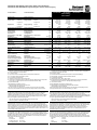
Technical Data
1)
Technische Daten
1)
1606-XLS180B
1606-XLS240E
1606-XLS240EC
11)
1606-XLS240EA
11)
1606-XLS240K 1606-XLS240F
Output Voltage Ausgangsspannung nom. DC 12-15V DC 24-28V DC 28-32V DC 48-56V
Factory Setting at Full Load Werkseinstellung bei Nennlast typ. 12.0V 24.1V 30.0V 48.0V
Output Current continuous Ausgangsstrom dauernd nom. 15A at 12V
13.5A at 15V
10A at 24V
9A at 28V
8.5A at 28V
7.5A at 32V
5A at 48V
4.3A at 56V
for typical 4s für typisch 4s nom. 22.5A at 12V
18A at 15V
15A at 24V
13.5A at 28V
12.75A at 28V
11.25A at 32V
7.5A at 48V
6.5A at 56V
Output Power continuous Ausgangsleistung dauernd nom. 180W 240W 240W 240W
for typical 4s für typisch 4s nom. 270W 360W 360W 360W
Output Ripple & Noise Voltage
2)
Ausgangswelligkeit
2
) max. 50mVpp 50mVpp 50mVpp 100mVpp
AC Input Voltage AC Eingangsspannung nom. AC 100-240V ±15% AC 100-240V ±15% AC 100-240V ±15% AC 100-240V ±15%
Input Frequency Eingangsfrequenz nom. 50-60Hz 50-60Hz 50-60Hz 50-60Hz
AC Input Current
3)
AC Eingangsstrom
3)
typ. 1.65A / 0.93A 2.22A / 1.22A 2.22A / 1.22A 2.22A / 1.22A
Power Factor
3)
Leistungsfaktor
3)
typ. 0.98 / 0.92 0.98 / 0.92 0.98 / 0.92 0.98 / 0.92
Allowed Voltage L or N to Earth Erlaubte Spannung L oder N zu Erde max. 300Vac 300Vac 300Vac 300Vac
EN 61000-3-2 EN 61000-3-2 PFC-Norm Yes / Ja Yes / Ja Yes / Ja Yes / Ja
Input Inrush Current
4)
Einschaltspitzenstrom
4)
typ. 7A peak 7A peak 7A peak 7A peak
Hold-up Time
3)
Pufferzeit
3)
typ. 32ms / 32ms 27ms / 28ms 22ms / 23ms 27ms / 28ms
Efficiency
3)
Wirkungsgrad
3)
typ. 91.5% / 91.8% 92.3% / 93.0% 92.3% / 93.0% 91.2% / 92.0%
Power Losses
3)
Verlustleistung
3)
typ. 16.7W / 16.1W 20.0W / 18.1W 20.0W / 18.1W 23.2W / 20.9W
Operational Temperature Range Betriebstemperaturbereich nom. -25°C - +70°C -25°C - +70°C -25°C - +70°C -25°C - +70°C
Output Derating Leistungsrücknahme +60°C to +70°C 6W/°C 6W/°C 6W/°C 6W/°C
Storage Temperature Range Lagertemperaturbereich nom. -40°C - +85°C -40°C - +85°C -40°C - +85°C -40°C - +85°C
Humidity
5)
Feuchte
5)
IEC 60068-2-30 5 - 95% r.H. 5 - 95% r.H. 5 - 95% r.H. 5 - 95% r.H.
Vibration Schwingen IEC 60068-2-6 2g 2g 2g 2g
Shock Schocken IEC 60068-2-27 30g 6ms, 20g 11ms 30g 6ms, 20g 11ms 30g 6ms, 20g 11ms 30g 6ms, 20g 11ms
Degree of Pollution (non-conductive) Verschmutzungsgrad (nicht leitend) EN 50178 / IEC 62103 2 2 2 2
Degree of Protection Schutzart EN 60529 IP20 IP20 IP20 IP20
Class of Protection Schutzklasse IEC 61140 I 6) I 6) I 6) I 6)
Over-temperature Protection Übertemperaturschutz OTP Yes / Ja Yes / Ja Yes / Ja Yes / Ja
Output Over-voltage Protection Überspannungsschutz am Ausgang OVP, max. 20Vdc 39Vdc 45Vdc 60Vdc
Touch (Leakage) Current
7)
PE- Ableitstrom
7)
max. 0.38mA / 0.74mA 0.38mA / 0.74mA 0.38mA / 0.74mA 0.38mA / 0.74mA
Return Voltage Resistance
8)
Rückspeisefestigkeit
8)
max. 18Vdc 35Vdc 35Vdc 58Vdc
Parallel Use
12)
Parallelschaltbar
12)
- Yes / Ja Yes / Ja Yes / Ja Yes / Ja
Serial Use
13)
Serienschaltbar
13)
- Yes / Ja Yes / Ja Yes / Ja Yes / Ja
Dimensions
9)
(WxHxD) Abmessungen
9)
(BxHxT) nom. 60x124x117mm 60x124x117mm 60x124x117mm 60x124x117mm
Weight Gewicht max. 930g, 2.05lb 900g, 1.98lb 900g, 1.98lb 900g, 1.98lb
Approvals Zulassungen - 10) 10) 10) 10)
1) All parameters are specified at 230Vac input voltage, nominal output current, 25°C ambient
and after a 5 minutes run-in time unless otherwise noted.
2) 50 Ohm measurement, bandwidth 20MHz
3) At 120Vac / 230Vac
4) Input inrush current electronically limited and is temperature independent.
5) Do not energize while condensation is present.
6) PE connection required (Ground).
7) Leakage current at 132Vac, 60Hz / 264Vac, 50Hz
8) Loads such as decelerating motors and inductors can feed voltage back to the output of the
power supply. The figure represents the maximum allowed feed back voltage
9) Depth without DIN-rail.
10) See datasheet or markings on the unit.
11) 1606-XLS240EC with conformal coated PC-board
1606-XLS240EA with ATEX approval
12) A fuse (or diode) on the output is only required if more than three units are paralleled.
13) Use only power supplies of the same type. The total voltage should not exceed 150Vdc.
1) Alle Werte gelten bei 230Vac Eingangsspannung, Nennausgangsstrom, 25°C Umgebungs-
temperatur und nach einer Aufwärmzeit von 5 Minuten, wenn nichts anderes angegeben ist.
2) 50 Ohm Messung, Bandbreite 20MHz
3) Bei 120Vac / 230Vac
4) Der Einschaltstromstoß ist elektronisch begrenzt und temperaturunabhängig.
5) Nicht betreiben, solange das Gerät Kondensation aufweist.
6) PE Verbindung erforderlich.
7) Ableitstrom bei 132Vac, 60Hz / 264Vac, 50Hz
8) Bremsende Motoren oder Induktivitäten können Spannung zum Ausgang des Netzteils
rückspeisen. Der Wert gibt die max. zulässige Rückspeisespannung an.
9) Tiefe ohne DIN-Schiene
10) Siehe Datenblatt oder Prüfzeichen auf dem Gerät.
11) 1606-XLS240EC mit schutzlackierter Leiterplatte1606-XLS240EC
1606-XLS240EA mit ATEX Zulassung
12) Bei mehr als drei Geräten wird eine Sicherung oder eine Diode zur Entkopplung benötigt.
13) Nur gleiche Geräte bis zu einer Gesamtspannung von 150Vdc
Installation
Use DIN-rails according to EN 60715 or EN 50022 with a height of 7.5 or 15mm. Mounting
orientation must be output terminals on top and input terminals on the bottom. For other
orientations see datasheet. Do not obstruct air flow as the unit is convection cooled. Ventilation
grid must be kept free of any obstructions. The following installation clearances must be kept
when power supplies are permanently fully loaded:
Left / right: 5mm (15mm in case the adjacent device is a heat source)
40mm on top, 20mm on the bottom of the unit.
Installation
Geeignet für DIN-Schienen entsprechend EN 60715 oder EN 50022 mit einer Höhe von 7,5 oder
15mm. Der Einbau hat so zu erfolgen, dass sich die Eingangsklemmen unten und die
A
usgangsklemmen oben befinden. Für andere Einbaulagen siehe Datenblatt. Luftzirkulation nicht
behindern! Das Gerät ist für Konvektionskühlung ausgelegt. Es ist für ungehinderte Luftzirkulation
zu sorgen. Folgende Einbauabstände sind bei dauerhafter Volllast einzuhalten:
Links / rechts: 5mm (15mm bei benachbarten Wärmequellen)
Oben: 40mm, unten 20mm vom Gerät.
Input Fuses
Internal input fuse: T6.3A (H.B.C.), not user accessible. The unit is tested and approved for
branch circuits up to 20A. An external protection is only required if the supplying branch has an
ampacity greater than this, however, in some countries local regulations might apply. Check local
codes and requirements. If an external fuse is necessary or utilized, minimum requirements need
to be considered to avoid nuisance tripping of the circuit breaker. A minimum value of 6A B- or 4A
C-Characteristic breaker should be used.
Sicherungen am Eingang
Das Gerät besitzt eine T6,3A (H.B.C.) Eingangssicherung, die nicht anwenderzugänglich ist. Das
Gerät ist geprüft und zugelassen zum Anschluss an Stromkreisen bis max. 20A. Ein zusätzlicher
externer Schutz ist nur erforderlich, wenn der Speisestromkreis mit einem höheren Wert
abgesichert ist oder nationale Richtlinien es vorschreiben. Falls ein externes Schutzelement
verwendet wird, soll dieses nicht kleiner als 6A B- oder 4A C-Charakteristik sein, um ein
fehlerhaftes Auslösen zu vermeiden.
Terminals and Wiring (see Fig. 6)
Use appropriate copper cables that are designed for a minimum operating temperature of 60°C
(for ambient up to 45°C) and 75°C (for ambient up to 60°C). Follow national installation codes and
regulations! Ensure that all strands of a stranded wire enter the terminal connection! Up to two
stranded wires with the same cross section are permitted in one connection point (except PE
wire). Ferrules are allowed, but not required.
Solid wire 0.5-6mm
2
Stranded wire 0.5-4mm
2
American wire gauge 20-10 AWG
Wire stripping length 7mm / 0.28inch
Anschlussklemmen und Verdrahtung (siehe Bild 6)
Verwenden Sie geeignete Kupferkabel, die mindestens für 60°C bei einer Umgebungstemperatur
bis zu 45°C und 75°C bei einer Umgebungstemperatur bis zu 60°C zugelassen sind. Beachten
Sie nationale Bestimmungen und Installationsvorschriften! Stellen Sie sicher, dass keine
einzelnen Drähte von Litzen abstehen. Bis zu zwei Leiter mit gleichem Querschnitt sind in einem
A
nschlusspunkt zulässig (außer Schutzleiter). Aderendhülsen sind erlaubt, aber nicht erforderlich.
Starrdraht 0,5-6mm
2
Litze 0,5-4mm
2
AWG 20-10 AWG
Abisolierlänge 7mm / 0,28inch

1606-XLS180, 1606-XLS240 1-Phase Power Supply Instruction Manual
1606-XLS180, 1606-XLS240 Bedienungsanleitung für 1-Phasen Stromversorgung
EMC Electromagnetic Compatibility
These power supplies are suitable for applications in industrial environment as well as in
residential, commercial and light industry environment without any restrictions. These devices
comply with FCC Part 15 rules.
CE mark is in conformance with EMC directive 2004/108/EC as well as the low-voltage directive
(LVD) 2006/95/EC.
EMC Immunity: EN 61000-6-1, EN 61000-6-2
EMC Emission EN 61000-6-3, EN 61000-6-4, FCC Part 15 Class B
EMV Elektromagnetische Verträglichkeit
Diese Stromversorgungen erfüllen die Anforderungen für Anwendungen in industrieller Umgebung
und für den Wohn-, Geschäfts- und Gewerbebereich ohne Einschränkungen. Die Geräte erfüllen
auch die Anforderungen der FCC Teil 15.
Das CE Zeichen ist angebracht und erklärt die Erfüllung der EMV Richtlinie 2004/108/EG wie
auch der Niederspannungsrichtlinie 2006/95/EG.
Störfestigkeit: EN 61000-6-1, EN 61000-6-2
Störaussendung: EN 61000-6-3, EN 61000-6-4, FCC Part 15 Klasse B
Indicators, LEDs
Overload LED DC-OK LED DC-OK Contact
Normal mode OFF ON Closed
During BonusPower
®
OFF ON Closed
Overload (Vout < 90%) ON OFF Open
Output short circuit ON OFF Open
Temperature Shut-down flashing OFF Open
No input power OFF OFF Open
Anzeigelampen
Overload LED DC-OK LED DC-OK Contact
Normalbetrieb AUS EIN geschlossen
Während BonusPower
®
AUS EIN geschlossen
Überlast (Vout < 90%) EIN AUS offen
A
usgangskurzschluss EIN AUS offen
Temperaturabschaltung blinken AUS offen
Keine Eingangsspannung AUS AUS offen
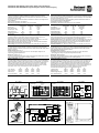
DC-OK Relay Contact (see Fig. 1)
This feature monitors the output voltage, which is produced by the power supply, and is
independent of a return voltage from a unit which is connected in parallel.
Contact closes when the output voltage reaches the adjusted value after turn-on of the power
supply or when the output voltage reaches 90% after a dip in the output.
Contact opens when the output voltage dips more than 10%. Short dips will be extended to a
length of 250ms. Dips shorter than 1ms will be ignored.
Contact ratings: max.: 60Vdc 0.3A, 30Vdc 1A, 30Vac 0.5A, resistive load, min. current 1mA
DC-OK Relais Kontakt (siehe Bild 1)
Diese Funktion überwacht die vom Gerät erzeugte Ausgangsspannung und lässt sich von einer
rückwärts eingespeisten Spannung nicht beeinflussen (z.B.: bei Parallelschaltung)
Kontakt schließt sobald nach dem Einschalten der Ausgang den eingestellten Wert erreicht oder
wenn nach Einbruch des Ausgangs die Spannung wieder >90% des eingestellten Wertes wird.
Kontakt öffnet sobald der Ausgang um mehr als 10% einbricht. Kurze Einbrüche werden auf
250ms verlängert. Einbrüche kürzer 1ms werden ignoriert.
Kontakt Belastbarkeit: max.: 60Vdc 0.3A, 30Vdc 1A, 30Vac 0.5A, (R-Last), min. Strom 1mA
Output- and Overload Characteristic
The unit is designed to support loads with a continuous power demand of up to 240W (1606-
XLS180B: 180W) and a short-term power demand of up to 360W (1606-XLS180B: 270W) without
damage or shut-down.
Output characteristic (see Fig. 2)
The curve in this figure is a typical curve for 24V unit. The other output voltages have an
equivalent and proportional performance.
BonusPower
®
time (see Fig. 3)
The curve in this figure shows the duration until the output voltage starts dipping when more than
240W (1606-XLS180B: 180W) is drawn (controlled by software).
Ausgangs- und Überlastverhalten
Die Stromversorgung ist zur Versorgung von Lasten mit einem Dauerleistungsbedarf bis zu 240W
(1606-XLS180B: 180W) und einem kurzzeitigem Leistungsbedarf bis 360W (1606-XLS180B:
270W) konstruiert ohne dabei Schaden zu nehmen.
Ausgangskennlinie (siehe Bild 2)
Die Kennlinie in diesem Bild ist die Kennlinie eines typischen 24V Gerätes. Die anderen
A
usgangsspannungen zeigen ein proportional vergleichbares Verhalten.
BonusPower
®
Zeit (siehe Bild 3)
Die Kennlinie in diesem Bild gibt die Dauer an bis die Ausgangsspannung sinkt, wenn mehr als
240W (1606-XLS180B: 180W) entnommen werden (softwaregesteuert).
Dielectric Strength (see Fig. 4)
The output voltage is floating and separated from the input according to SELV (IEC/EN 60950-1)
and PELV (EN 60204-1, EN 50178; IEC 62103, IEC 60364-4-41) requirements. Type and factory
tests are conducted by the manufacturer. Field tests may be conducted in the field using the
appropriate test equipment which applies the voltage with a slow ramp (2s up and 2s down).
Connect all phase-terminals together as well as all output poles before the test is conducted.
When testing, set the cut-off current settings to the value in the table below.
A B C D
Type Test (60s) 2500Vac 3000Vac 500Vac 500Vac
Factory Test (5s) 2500Vac 2500Vac 500Vac 500Vac
Field Test (5s) 2000Vac 2000Vac 500Vac 500Vac
Cut-off current setting >10mA >10mA >20mA >1mA
Isolationsfestigkeit (siehe Bild 4)
Die Ausgangsspannung hat keinen Bezug zur Erde oder Schutzleiter und ist zum Eingang nach
den SELV (IEC/EN 60950-1) und PELV (EN 60204-1, EN 50178, IEC 62103, IEC 60364-4-41)
Standards getrennt. Typ- und Stückprüfungen werden beim Hersteller durchgeführt. Wieder-
holungsprüfungen dürfen mittels geeigneten Prüfgenerators mit langsam (2s) ansteigenden und
abfallenden Spannungsrampen in der Anwendung erfolgen. Vor den Tests sind alle Phasen wie
auch alle Ausgangspole miteinander zu verbinden. Während der Tests darf die Strom-
A
bschaltschwelle nicht kleiner als der in der Liste angegebene Wert sein.
A B C D
Typprüfung (60s) 2500Vac 3000Vac 500Vac 500Vac
Stückprüfung (5s) 2500Vac 2500Vac 500Vac 500Vac
Wiederholungsprüfung (5s) 2000Vac 2000Vac 500Vac 500Vac
Strom- Abschaltschwelle >10mA >10mA >20mA >1mA
Fig. 1 / Bild 1
DC-OK-Signal
Fig. 2 / Bild 2
Output Characteristic /Ausgangskennlinie
Fig. 3 / Bild 3
BonusPower
®
Time / Zeit
Fig. 4 / Bild 4
Insulation / Isolation
250ms
90% V
ADJ
<1ms
10%
open
V
OUT
=
V
ADJ
openclosed closed
>1ms
c
o
n
t
i
n
u
o
u
s
Output Voltage
0
0 5 10 15 20
4
8
12
28V
16
20
24
25
A
Output Current
s
h
o
r
t
-
t
e
r
m
Adjustment
Range
Bonus Time
0
110 120 130 140 150
160%
Output Power
1
2
3
7
4
5
6
8
9
10s
m
i
n
m
a
x
typ
A
D
C
B
B
Input DC-ok
Earth
Output
-
+
N
L
Fig. 5 / Bild 5
Terminals / Anschlüsse
Fig. 6 / Bild 6
Functional Diagram / Funktionsschaltbild
Fig. 7 / Bild 7
Dimensions / Abmessungen
Insert wire / Draht einführen
+
+
-
-
DC-ok
contact
Output
Over-
Voltage
Protection
PFC
Converter
Output
Voltage
Regulator
Power
Converter
Output
Filter
DC-ok
Relay
Output
Voltage
Monitor
Output
Power
Manager
Temper-
ature
Shut-
down
Overload
lamp
DC-ok
lamp
Input Fuse
Input Filter
Input Rectifier
Active Transient Filter &
Inrush Current Limiter
V
OUT
L
N
Snap the lever / Hebel schließen
10000044634 (version 01)
PU-339.013.38-10A
Transcripción de documentos
1 2 3 4 5 6 EN DE FR ES IT PT Instruction Manual Bedienungsanleitung Manual d'instructions Manual de instrucciones Manuale di Istruzione Manual de Instruções DC Power Supply DC Stromversorgung DC Alimentation d'Énergie DC Fuente De Alimentación DC Gruppo di alimentazione DC Fonte De Alimentação Read this first! 1606-XLS180 1606-XLS240 English 1 Before operating this unit please read this manual thoroughly and retain this manual for future reference! This device may only be installed and put into operation by qualified personnel. If damage or malfunction should occur during operation, immediately turn power off and send unit to the factory for inspection. The unit does not contain serviceable parts. The tripping of an internal fuse (if included) is caused by an internal defect. The information presented in this document is believed to be accurate and reliable and may change without notice. For any clarifications the English translation will be used. Intended Use: This power supply is designed for installation in an enclosure and is intended for general use such as in industrial control, office, communication, and instrumentation equipment. Do not use this power supply in aircraft, trains and nuclear equipment where malfunction may cause severe personal injury or threaten human life. WARNING Risk of electrical shock, fire, personal injury or death. 1) Do not use the power supply without proper grounding (Protective Earth). 2) Turn power off before working on the device. Protect against inadvertent re-powering. 3) Make sure that the wiring is correct by following all local and national codes. 4) Do not modify or repair the unit. 5) Do not open the unit as high voltages are present inside. 6) Use caution to prevent any foreign objects from entering the housing. 7) Do not use in wet locations or in areas where moisture or condensation can be expected. 8) Do not touch during power-on, and immediately after power-off. Hot surfaces may cause burns. CAUTION Reduction of output current may be necessary when: 1) Minimum installation clearance can not be met. 2) Altitude is higher than 2000m. 3) Device is used above +60°C ambient. 4) Mounting orientation is other than input terminal located at the bottom and output at the top. 5) Airflow for convection cooling is obstructed. Details for de-rating can be found in this manual and in the datasheet of the unit.. WARNING EXPLOSION HAZARDS (Notes for use in hazardous locations only) Units which are marked with "Class I Div 2" are suitable for use in non-hazardous or Class I Division 2 Groups A, B, C, D locations only. Substitution of components may impair suitability for Class I Division 2 environment. Do not disconnect equipment unless power has been switched off. Wiring must be in accordance with Class I, Division 2 wiring methods of the National Electrical Code, NFPA 70, and in accordance with other local or national codes. Units which are marked with "EX (Hexagon Symbol) II 3G Ex nA nC IIC T4 are suitable for use in Class 1 Zone 2 Groups IIa, IIb and IIc locations and must be built-in in an IP54 enclosure. Number of ATEX certificate: EPS 09 ATEX 1 236 X Vor Inbetriebnahme lesen! Deutsch 2 Bitte lesen Sie diese Warnungen und Hinweise sorgfältig durch, bevor Sie das Gerät in Betrieb nehmen. Bewahren Sie die Anleitung zum Nachlesen auf. Das Gerät darf nur durch fachkundiges und qualifiziertes Personal installiert werden. Bei Funktionsstörungen oder Beschädigungen schalten Sie sofort die Versorgungsspannung ab und senden das Gerät zur Überprüfung ins Werk. Das Gerät beinhaltet keine Servicebauteile. Interne Sicherungen (falls vorhanden) lösen nur bei Gerätedefekt aus. Die angegebenen Daten dienen allein der Produktbeschreibung und sind nicht als zugesicherte Eigenschaften im Rechtssinne aufzufassen. Im Zweifelsfall gilt der englische Text. Bestimmungsgemäßer Gebrauch: Diese Stromversorgung ist für den Einbau in ein Gehäuse konzipiert und zur Verwendung für allgemeine elektronische Geräte, wie z.B. Industriesteuerungen, Bürogeräte, Kommunikationsgeräte oder Messgeräte geeignet. Benutzen Sie diese Stromversorgung nicht in Steuerungsanlagen von Flugzeugen, Zügen oder nuklearen Einrichtungen, in denen eine Funktionsstörung zu schweren Verletzungen führen oder Lebensgefahr bedeuten kann. WARNUNG Missachtung nachfolgender Punkte kann einen elektrischen Schlag, Brände, schwere Unfälle oder Tod zur Folge haben. 1) Betreiben Sie die Stromversorgung nie ohne Schutzleiter. 2) Schalten Sie die Eingangsspannung vor Installations-, Wartungs- oder Änderungsarbeiten ab und sichern Sie diese gegen unbeabsichtigtes Wiedereinschalten. 3) Sorgen Sie für eine ordnungsgemäße und fachgerechte Verdrahtung. 4) Führen Sie keine Änderungen oder Reparaturversuche am Gerät durch. 5) Gerät niemals öffnen. Im Inneren befinden sich gefährliche Spannungen. 6) Verhindern Sie das Eindringen von Fremdkörpern, wie z.B. Büroklammern und Metallteilen. 7) Betreiben Sie das Gerät nicht in feuchter Umgebung oder in einer Umgebung, bei der mit Betauung oder Kondensation zu rechnen ist. 8) Gehäuse nicht während des Betriebes oder kurz nach dem Abschalten berühren. Heiße Oberflächen können Verletzungen verursachen. VORSICHT Rücknahme der Ausgangsleistung kann erforderlich sein: 1) wenn die minimalen Einbauabstände nicht eingehalten werden können. 2) bei Aufstellhöhen über 2000m. 3) Betrieb bei Umgebungstemperaturen über +60°C. 4) bei Einbaulagen abweichend von der Standardeinbaulage (Eingang unten, Ausgang oben). 5) bei behinderter Luftzirkulation. Details zur Leistungsrücknahme befinden sich in dieser Betriebsanleitung oder im Datenblatt des Gerätes. ACHTUNG EXPLOSIONSGEFAHR! (Hinweise für den Betrieb in explosionsgefährdeter Umgebung) Geräte, die am Leistungsschild mit "Class I Div 2" gekennzeichnet sind, sind für den Einsatz in Klasse I Division 2 Gruppen A,B,C,D oder für nicht explosionsgefährdete Aufstellorte geeignet. Veränderungen an Bauteilen können die Tauglichkeit für Klasse I Division 2 beeinträchtigen. Anschlüsse nicht trennen, solange Spannung anliegt. Anschluss muss unter Berücksichtigung der Anforderungen nach Klasse I Division 2 Artikel 501-4(b) des National Electrical Code, NFPA 70, erfolgen. Geräte, die am Leistungsschild mit "EX (Hexagon Symbol) II 3G Ex nA nC IIC T4 gekennzeichnet sind, können an Klasse 1 Zone 2 Gruppe IIa, IIb and IIc Aufstellorten verwendet werden. Die Stromversorgungen müssen in ein IP54 Gehäuse eingebaut werden. Nummer des Zertifikates: EPS 09 ATEX 1 236 X. A lire avant mise sous tension! Français 3 Merci de lire ces instructions de montage et d'entretien avant de mettre l'alimentation sous tension. Conservez ce manuel qui vous sera toujours utile. Cette alimentation doit être installée par du personnel qualifié et compétent. Le déclenchement du fusible interne traduit très probablement un défaut au niveau de l'appareil. Si un défaut quelconque apparaît en cours de fonctionnement, débrancher au plus vite l'alimentation. Dans ce deux cas de figure, il convient de faire contrôler l'alimentation en usine! Les données indiquées dans ce document servent uniquement à donner une description du produit et n'ont aucune valeur juridique. En cas de divergences, le texte anglais fait foi. Utilisation: Cet appareil est conçu pour être installé dans une armoire et pour tous les équipements électroniques, tel que l'équipement industriel de commande, l'équipement de bureau, le matériel de communication et les instruments de mesures. N'utilisez pas cet appareil pour l'équipement de commandes dans les avions, les trains et l'équipement atomique où un problème de fonctionnement de l'alimentation pourrait causer des blessures graves ou menacer la vie humaine. AVERTISSEMENT Prendre en compte les points suivants, afin d'éviter toute détérioration électrique, incendie, dommage aux personnes ou mort. 1) ne jamais faire fonctionner l'alimentation sans raccordement à la terre ! 2) débrancher l'installation avant toute intervention sur l'alimentation (ou démontage) et s'assurer qu'il n'y a pas risque de redémarrage. 3) s'assurer que le câblage a été fait selon les prescriptions 4) ne pas effectuer de réparations ou modifications sur l'alimentation 5) ne pas ouvrir l'appareil. Des tensions importantes passent à l'intérieur. 6) veiller à ce qu'aucun objet ne rentre en contact avec l'intérieur de l'alimentation (trombones, pièces métalliques) 7) ne pas faire fonctionner l'appareil dans un environnement humide ou à l'extérieur, non protégé. Ne pas utiliser l'appareil dans un environnement où il peut y avoir de la condensation. 8) ne pas toucher le carter pendant le fonctionnement ou après la mise sous tension. Surface chaude risquant d’entraîner des blessures. ATTENTION Des limitations de puissance de sortie peuvent apparaître si : 1) les distances d'installation mini. ne peuvent être observées 2) installation à une altitude > 2000 m 3) pour des fonctionnements en charge et avec une température ambiante > 60°C 4) pour des positions de montage différentes de la préconisation standard (entrée dessous, sortie en haut). 5) lorsque la circulation d'air est gênée D'autres informations sont disponibles dans la documentation de mise en service ATTENTION RISQUE D’ EXPLOSION (Utilisation Class I Div 2) Les appareils portant la marque ‘Class I Div 2’ au niveau de la plaque signalétique sont prévus pour fonctionner en Classe I, Division 2, Groupes A,B,C,D ou pour un environnement non explosif et non dangereux. Le remplacement de composants peut rendre le matériel impropre à une utilisation en Classe 1, Division 2. Ne déconnecter l’équipement qu’ hors tension ou en zone connue comme non dangereuse. Le raccordement doit obligatoirement tenir compte des exigences de la classe 1, division 2, article 501-4(b) du National Electrical Code, NFPA 70. Lea primero! Español 4 Conserve este manual como referencia para futuras consultas. La fuente de alimentación solo puede ser instalada y puesta en funcionamiento por personal cualificado. Por favor lea detenidamente este manual antes de conectar la fuente de alimentación. Cuando se funde un fusible interno, existe gran probabilidad de un fallo interno en el equipo.Si se produce un fallo o mal funcionamiento durante la operación, desconecte inmediatamente la tensión de alimentación. En ambos casos, el equipo debe ser inspeccionado en fábrica. La información presentada en este documento es exacta y fiable en cuanto a la descripción del producto y puede cambiar sin aviso. En casa de duda, prevalece el texto inglés. Uso apropiado: Este equipo ha sido diseñado para su instalación en un ambiente cerrado y ha sido concebido para uso general en instalaciones de control industrial, oficinas, comunicaciones y equipos de instrumentación. No emplee este equipo en aeronaves, trenes e instalaciones atómicas, donde un mal funcionamiento de la fuente de alimentación puede ocasionar lesiones graves o riesgo mortal. ADVERTENCI A Riesgo de descarga eléctrica, incendio, accidente grave o muerte. 1) No conectar nunca la unidad sin conexión de puesta a tierra. 2) Desconectar la tensión de red antes de trabajar en la fuente de alimentación. Evite una posible reconexión involuntaria. 3) Asegurarse de que el cableado es correcto de acuerdo a los códigos locales y nacionales. 4) No realizar ninguna modificación o reparación de la unidad. 5) No abrir nunca la unidad. En el interior existe riesgo de altas tensiones. 6) Evitar la introducción en la carcasa de objetos extraños. 7) No usar el equipo en ambientes húmedos. No operar el equipo en ambientes donde se espere la formación de rocío o condensación. 8) No tocar durante el funcionamiento ni inmediatamente después del apagado. El calor de la superficie puede causar quemaduras graves ATENCIÓN La deriva en la tensión de salida se produce: 1) cuando no pueden mantenerse las distancias mínimas de montaje. 2) en caso de que el montaje se realice en altitudes superiores a los 2000 m. 3) en caso de funcionamiento a plena carga y temperaturas ambientales superiores a +60ºC. 4) en caso de posiciones de montaje diferentes a la posición de montaje estándar (terminales de entrada abajo y terminales de salida arriba). 5) en caso de que la circulación de aire para la refrigeración por conducción esté obstruida. Puede encontrar más detalles del caso de deriva en este manual. ATENCIÓN PELIGRO DE EXPLOSIÓN! (Uso apropiado Class I Div 2) Los equipos marcados con la expresión "Class I Div 2" son adecuados para su uso en ambientes no peligrosos y en entornos con la Clase I División 2 Grupos A, B, C, D. La sustitución de componentes puede perjudicar la idoneidad para la Clase I División 2. No desconecte el equipo a menos que la tensión de alimentación esté desconectada. El conexionado debe cumplir con la Clase I División 2 métodos de conexión del Código Nacional Eléctrico NFPA 70 o con el resto de códigos locales o nacionales. Leggere prima questa parte! Italiano 5 Prima di collegare il sistema di alimentazione elettrica si prega di leggere attentamente le seguenti avvertenze. Conservare le istruzioni per la consultazione futura. Il sistema di alimentazione elettrica deve essere installato solo da personale competente e qualificato. In caso di intervento del fusibile interno, molto probabilmente l'apparecchio è guasto. Se durante il funzionamento si verificano anomalie o guasti, scollegare immediatamente la tensione di alimentazione. In entrambi i casi è necessario far controllare l'apparecchio dal produttore! I dati sono indicati solo a scopo descrittivo del prodotto e non vanno considerati come caratteristiche garantite dell'apparecchio.In caso di differenze o problemi è valido il testo inglese Uso previsto: Questo apparecchio è previsto per il montaggio in un rack per moduli elettronici, ad esempio per controllori industriali, apparecchiature per ufficio, unità di comunicazione o apparecchi di misura. Non utilizzare l'apparecchio in impianti di controllo di aerei, di treni o di impianti nucleari in cui il suo eventuale guasto può comportare gravi lesioni o la morte di persone. AVVERTENZA Il mancato rispetto delle seguenti norme può provocare folgorazione elettrica, incendi, gravi incidenti e perfino la morte. 1) Non far funzionare in nessun caso il sistema di alimentazione elettrica senza conduttore di protezione! 2) Prima di eseguire interventi di installazione, di manutenzione o di modifica scollegare la tensione di rete ed adottare tutti i provvedimenti necessari per impedirne il ricollegamento non intenzionale. 3) Assicurare un cablaggio regolare e corretto. 4) Non tentare di modificare o di riparare da soli l'apparecchio. 5) Non aprire l'apparecchio. Al suo interno sono applicate tensioni elettriche pericolose. 6) Impedire la penetrazione di corpi estranei nell'apparecchio, ad esempio fermagli o altri oggetti metallici. 7) Non far funzionare l'apparecchio in un ambiente umido. Non far funzionare l'apparecchio in un ambiente soggetto alla formazione di condensa o di rugiada. 8) Non toccare quando acceso e subito dopo lo spegnimento. La superficie calda può causare scottature. ATTENZIONE È necessario ridurre la potenza di uscita se: 1) non è possibile rispettare le distanze minime di montaggio; 2) l'apparecchio viene installato in un luogo di altitudine maggiore di 2000 m; 3) il funzionamento è a pieno carico a temperatura ambiente maggiore di +60°C; 4) la posizione di montaggio differisce da quella standard (ingresso in basso, uscita in alto). 5) è ostacolata la libera circolazione dell'aria. Ulteriori informazioni sono riportate in questo manuale. ATTENZIONE: PERICOLO DI ESPLOSIONE! (Uso previsto Class I Div 2) Gli apparecchi la cui targhetta riporta "Class I Div 2" sono adatti per l'impiego in ambienti di classe I, divisione 2, gruppi A, B, C e D o non soggetti al pericolo di esplosione. La modifica dei componenti possono influenzare negativamente l'idoneità per ambienti di classe I, divisione 2.Non aprire i morsetti con tensione di alimentazione collegata. Il collegamento deve essere eseguito nel rispetto dei requisiti previsti dalla classe I, divisione 2, articolo 501-4(b) del National Electrical Code, NFPA 70. Leia primeiro! Portuguès 6 Recomendamos a leitura cuidadosa das seguintes advertências e observações, antes de colocar em funcionamento a fonte de alimentação. Guarde as Instruções para futura consulta, em casos de dúvida. A fonte de alimentação deverá ser instalada apenas por profissionais da área, tecnicamente qualificados. Se o fusível interno se fundir, é grande a possibilidade de existir um defeito no aparelho. Se por acaso, durante a utilização ocorrer algum defeito de funcionamento ou dano, desligue imediatamente a tensão de alimentação. Em ambos os casos, será necessária uma verificação na Fábrica! Os dados mencionados têm como finalidade somente a descrição do produto, e não devem ser interpretados como propriedades garantidas no sentido jurídico. Em caso de duvidas aplica-se o texto em inglês. Utilize: Apenas para o fim pré-estabelecido. Este aparelho foi concebido para ser montado dentro de invólucros, caixas ou armários para aparelhos eletrônicos em geral, como, por exemplo, comandos de instalações industriais, aparelhos para escritórios, aparelhos de comunicação ou instrumentos de medida e quadros eléctricos. Não utilize este aparelho em sistemas de comando de aviões, de comboios ou em instalações movidas por energia nuclear, nos quais um defeito de funcionamento poderá causar danos graves ou significar risco de morte. ATENÇÃO A não observância ou o incumprimento dos pontos a seguir mencionados, poderá causar uma descarga elétrica, incêndios, acidentes graves ou morte. 1) Não use a fonte de alimentação sem o condutor de proteção terra! 2) Antes de trabalhos de instalação, manutenção ou modificação, desligue a tensão de alimentação, protegendo-a contra uma nova ligação involuntária. 3) As ligações devem ser efectuadas apenas por profissionais competentes. 4) Não efectue nenhuma modificação ou tentativa de reparação no aparelho. Quando necessário contacte o seu distribuidor. 5) Não abra o aparelho mesmo quando desligado. No seu interior existem condensadores que podem estar carregados electricamente. 6) Proteger a fonte de alimentação contra a introdução inadvertida de corpos metálicos, como por ex., clipes ou outras peças de metal. 7) Não usar o aparelho em ambientes húmidos. Não usar o aparelho em ambientes propensos a condensações. 8) Não tocar enquanto estiver em funcionamento, nem após a desligar. A superficie poderá estar quente e provocar lesões. CUIDADO Será necessário reduzir a potência de saída nos seguintes casos: 1) Quando não forem observadas as distâncias mínimas de montagem. 2) Quando instaladas a altitudes superiores a 2000m. 3) Existencia de temperatura ambiente superior a +60ºC, em plena carga do aparelho. 4) Montagem invertida do aparelho (Entrada em baixo, saída em cima). 5) Montagem em ambiente sem ventilação. No presente manual de funcionamento encontram-se ainda outras informações. ATENÇÃO, RISCO DE EXPLOSÃO! (Utilize Class I Div2) Aparelhos que contêm na sua placa de dados elétricos o texto “Class I Div 2” são apropriados para a aplicação na Classe I, divisão 2, Grupos A, B, C, D ou também para locais de instalação isentos de riscos de explosão. Modificações efetuadas em componentes podem restringir ou reduzir a adequação para aplicação na Classe I, Divisão 2. As ligações não devem ser separadas enquanto estiverem ligadas a uma fonte de alimentação elétrica. As ligações devem ser efetuadas levando-se em consideração as exigências normativas da Classe I, Divisão 2. Rockwell Automation CH-5001 Aarau, Switzerland Fax +41 62 837 2202 © 2011 by Allen-Bradley Company, LCC Industrial Components Business 1201 South Second Street Milwaukee, WI 53204-2496 USA Phone 440 646 5800 1606-XLS180, 1606-XLS240 1-Phase Power Supply Instruction Manual 1606-XLS180, 1606-XLS240 Bedienungsanleitung für 1-Phasen Stromversorgung Technical Data 1) Technische Daten 1) Output Voltage Ausgangsspannung Factory Setting at Full Load Output Current continuous Werkseinstellung bei Nennlast Ausgangsstrom dauernd for typical 4s Output Power continuous for typical 4s Output Ripple & Noise Voltage 2) Ausgangsleistung 1606-XLS180B 1606-XLS240E 1606-XLS240EC11) 1606-XLS240EA11) 1606-XLS240K 1606-XLS240F nom. DC 12-15V DC 24-28V DC 28-32V DC 48-56V typ. nom. 12.0V 15A at 12V 13.5A at 15V 22.5A at 12V 18A at 15V 180W 270W 24.1V 10A at 24V 9A at 28V 15A at 24V 13.5A at 28V 240W 360W 30.0V 8.5A at 28V 7.5A at 32V 12.75A at 28V 11.25A at 32V 240W 360W 48.0V 5A at 48V 4.3A at 56V 7.5A at 48V 6.5A at 56V 240W 360W für typisch 4s nom. dauernd für typisch 4s nom. nom. 2 Ausgangswelligkeit ) max. 50mVpp 50mVpp 50mVpp 100mVpp nom. nom. typ. typ. max. PFC-Norm AC 100-240V ±15% 50-60Hz 1.65A / 0.93A 0.98 / 0.92 300Vac Yes / Ja AC 100-240V ±15% 50-60Hz 2.22A / 1.22A 0.98 / 0.92 300Vac Yes / Ja AC 100-240V ±15% 50-60Hz 2.22A / 1.22A 0.98 / 0.92 300Vac Yes / Ja AC 100-240V ±15% 50-60Hz 2.22A / 1.22A 0.98 / 0.92 300Vac Yes / Ja AC Input Voltage Input Frequency 3) AC Input Current Power Factor 3) Allowed Voltage L or N to Earth EN 61000-3-2 AC Eingangsspannung Eingangsfrequenz 3) AC Eingangsstrom Leistungsfaktor 3) Erlaubte Spannung L oder N zu Erde EN 61000-3-2 Input Inrush Current 4) Einschaltspitzenstrom 4) typ. 7A peak 7A peak 7A peak 7A peak Hold-up Time 3) Pufferzeit 3) typ. 32ms / 32ms 27ms / 28ms 22ms / 23ms 27ms / 28ms typ. typ. 91.5% / 91.8% 16.7W / 16.1W 92.3% / 93.0% 20.0W / 18.1W 92.3% / 93.0% 20.0W / 18.1W 91.2% / 92.0% 23.2W / 20.9W 3) 3) Efficiency Power Losses 3) Wirkungsgrad Verlustleistung 3) Operational Temperature Range Output Derating Storage Temperature Range Betriebstemperaturbereich Leistungsrücknahme Lagertemperaturbereich nom. +60°C to +70°C nom. -25°C - +70°C 6W/°C -40°C - +85°C -25°C - +70°C 6W/°C -40°C - +85°C -25°C - +70°C 6W/°C -40°C - +85°C -25°C - +70°C 6W/°C -40°C - +85°C Humidity 5) Feuchte 5) IEC 60068-2-30 5 - 95% r.H. 5 - 95% r.H. 5 - 95% r.H. 5 - 95% r.H. Vibration Shock Schwingen Schocken IEC 60068-2-6 IEC 60068-2-27 2g 30g 6ms, 20g 11ms 2g 30g 6ms, 20g 11ms 2g 30g 6ms, 20g 11ms 2g 30g 6ms, 20g 11ms Degree of Pollution (non-conductive) Degree of Protection Class of Protection Over-temperature Protection Output Over-voltage Protection Touch (Leakage) Current 7) Return Voltage Resistance 8) Verschmutzungsgrad (nicht leitend) Schutzart Schutzklasse Übertemperaturschutz Überspannungsschutz am Ausgang PE- Ableitstrom 7) Rückspeisefestigkeit 8) EN 50178 / IEC 62103 EN 60529 IEC 61140 OTP OVP, max. max. max. 2 IP20 I 6) Yes / Ja 20Vdc 0.38mA / 0.74mA 18Vdc 2 IP20 I 6) Yes / Ja 39Vdc 0.38mA / 0.74mA 35Vdc 2 IP20 I 6) Yes / Ja 45Vdc 0.38mA / 0.74mA 35Vdc 2 IP20 I 6) Yes / Ja 60Vdc 0.38mA / 0.74mA 58Vdc Parallel Use 12) Serial Use 13) Parallelschaltbar 12) Serienschaltbar 13) - Yes / Ja Yes / Ja Yes / Ja Yes / Ja Yes / Ja Yes / Ja Yes / Ja Yes / Ja Dimensions 9) (WxHxD) Weight Abmessungen 9) (BxHxT) Gewicht nom. max. 60x124x117mm 930g, 2.05lb 60x124x117mm 900g, 1.98lb 60x124x117mm 900g, 1.98lb 60x124x117mm 900g, 1.98lb Approvals Zulassungen - 10) 10) 10) 10) 1) All parameters are specified at 230Vac input voltage, nominal output current, 25°C ambient and after a 5 minutes run-in time unless otherwise noted. 2) 50 Ohm measurement, bandwidth 20MHz 3) At 120Vac / 230Vac 4) Input inrush current electronically limited and is temperature independent. 5) Do not energize while condensation is present. 6) PE connection required (Ground). 7) Leakage current at 132Vac, 60Hz / 264Vac, 50Hz 8) Loads such as decelerating motors and inductors can feed voltage back to the output of the power supply. The figure represents the maximum allowed feed back voltage 9) Depth without DIN-rail. 10) See datasheet or markings on the unit. 11) 1606-XLS240EC with conformal coated PC-board 1606-XLS240EA with ATEX approval 12) A fuse (or diode) on the output is only required if more than three units are paralleled. 13) Use only power supplies of the same type. The total voltage should not exceed 150Vdc. 1) Alle Werte gelten bei 230Vac Eingangsspannung, Nennausgangsstrom, 25°C Umgebungstemperatur und nach einer Aufwärmzeit von 5 Minuten, wenn nichts anderes angegeben ist. 2) 50 Ohm Messung, Bandbreite 20MHz 3) Bei 120Vac / 230Vac 4) Der Einschaltstromstoß ist elektronisch begrenzt und temperaturunabhängig. 5) Nicht betreiben, solange das Gerät Kondensation aufweist. 6) PE Verbindung erforderlich. 7) Ableitstrom bei 132Vac, 60Hz / 264Vac, 50Hz 8) Bremsende Motoren oder Induktivitäten können Spannung zum Ausgang des Netzteils rückspeisen. Der Wert gibt die max. zulässige Rückspeisespannung an. 9) Tiefe ohne DIN-Schiene 10) Siehe Datenblatt oder Prüfzeichen auf dem Gerät. 11) 1606-XLS240EC mit schutzlackierter Leiterplatte1606-XLS240EC 1606-XLS240EA mit ATEX Zulassung 12) Bei mehr als drei Geräten wird eine Sicherung oder eine Diode zur Entkopplung benötigt. 13) Nur gleiche Geräte bis zu einer Gesamtspannung von 150Vdc Installation Installation Use DIN-rails according to EN 60715 or EN 50022 with a height of 7.5 or 15mm. Mounting orientation must be output terminals on top and input terminals on the bottom. For other orientations see datasheet. Do not obstruct air flow as the unit is convection cooled. Ventilation grid must be kept free of any obstructions. The following installation clearances must be kept when power supplies are permanently fully loaded: Left / right: 5mm (15mm in case the adjacent device is a heat source) 40mm on top, 20mm on the bottom of the unit. Geeignet für DIN-Schienen entsprechend EN 60715 oder EN 50022 mit einer Höhe von 7,5 oder 15mm. Der Einbau hat so zu erfolgen, dass sich die Eingangsklemmen unten und die Ausgangsklemmen oben befinden. Für andere Einbaulagen siehe Datenblatt. Luftzirkulation nicht behindern! Das Gerät ist für Konvektionskühlung ausgelegt. Es ist für ungehinderte Luftzirkulation zu sorgen. Folgende Einbauabstände sind bei dauerhafter Volllast einzuhalten: Links / rechts: 5mm (15mm bei benachbarten Wärmequellen) Oben: 40mm, unten 20mm vom Gerät. Input Fuses Sicherungen am Eingang Internal input fuse: T6.3A (H.B.C.), not user accessible. The unit is tested and approved for branch circuits up to 20A. An external protection is only required if the supplying branch has an ampacity greater than this, however, in some countries local regulations might apply. Check local codes and requirements. If an external fuse is necessary or utilized, minimum requirements need to be considered to avoid nuisance tripping of the circuit breaker. A minimum value of 6A B- or 4A C-Characteristic breaker should be used. Das Gerät besitzt eine T6,3A (H.B.C.) Eingangssicherung, die nicht anwenderzugänglich ist. Das Gerät ist geprüft und zugelassen zum Anschluss an Stromkreisen bis max. 20A. Ein zusätzlicher externer Schutz ist nur erforderlich, wenn der Speisestromkreis mit einem höheren Wert abgesichert ist oder nationale Richtlinien es vorschreiben. Falls ein externes Schutzelement verwendet wird, soll dieses nicht kleiner als 6A B- oder 4A C-Charakteristik sein, um ein fehlerhaftes Auslösen zu vermeiden. Terminals and Wiring (see Fig. 6) Anschlussklemmen und Verdrahtung (siehe Bild 6) Use appropriate copper cables that are designed for a minimum operating temperature of 60°C (for ambient up to 45°C) and 75°C (for ambient up to 60°C). Follow national installation codes and regulations! Ensure that all strands of a stranded wire enter the terminal connection! Up to two stranded wires with the same cross section are permitted in one connection point (except PE wire). Ferrules are allowed, but not required. Solid wire 0.5-6mm2 Stranded wire 0.5-4mm2 American wire gauge 20-10 AWG Wire stripping length 7mm / 0.28inch Verwenden Sie geeignete Kupferkabel, die mindestens für 60°C bei einer Umgebungstemperatur bis zu 45°C und 75°C bei einer Umgebungstemperatur bis zu 60°C zugelassen sind. Beachten Sie nationale Bestimmungen und Installationsvorschriften! Stellen Sie sicher, dass keine einzelnen Drähte von Litzen abstehen. Bis zu zwei Leiter mit gleichem Querschnitt sind in einem Anschlusspunkt zulässig (außer Schutzleiter). Aderendhülsen sind erlaubt, aber nicht erforderlich. Starrdraht 0,5-6mm2 Litze 0,5-4mm2 AWG 20-10 AWG Abisolierlänge 7mm / 0,28inch 1606-XLS180, 1606-XLS240 1-Phase Power Supply Instruction Manual 1606-XLS180, 1606-XLS240 Bedienungsanleitung für 1-Phasen Stromversorgung EMC Electromagnetic Compatibility EMV Elektromagnetische Verträglichkeit These power supplies are suitable for applications in industrial environment as well as in residential, commercial and light industry environment without any restrictions. These devices comply with FCC Part 15 rules. CE mark is in conformance with EMC directive 2004/108/EC as well as the low-voltage directive (LVD) 2006/95/EC. EMC Immunity: EN 61000-6-1, EN 61000-6-2 EMC Emission EN 61000-6-3, EN 61000-6-4, FCC Part 15 Class B Diese Stromversorgungen erfüllen die Anforderungen für Anwendungen in industrieller Umgebung und für den Wohn-, Geschäfts- und Gewerbebereich ohne Einschränkungen. Die Geräte erfüllen auch die Anforderungen der FCC Teil 15. Das CE Zeichen ist angebracht und erklärt die Erfüllung der EMV Richtlinie 2004/108/EG wie auch der Niederspannungsrichtlinie 2006/95/EG. Störfestigkeit: EN 61000-6-1, EN 61000-6-2 Störaussendung: EN 61000-6-3, EN 61000-6-4, FCC Part 15 Klasse B Indicators, LEDs Anzeigelampen Overload LED OFF OFF ON ON flashing OFF Normal mode During BonusPower® Overload (Vout < 90%) Output short circuit Temperature Shut-down No input power DC-OK LED ON ON OFF OFF OFF OFF DC-OK Contact Closed Closed Open Open Open Open Overload LED AUS AUS EIN EIN blinken AUS Normalbetrieb Während BonusPower® Überlast (Vout < 90%) Ausgangskurzschluss Temperaturabschaltung Keine Eingangsspannung DC-OK LED EIN EIN AUS AUS AUS AUS DC-OK Contact geschlossen geschlossen offen offen offen offen DC-OK Relay Contact (see Fig. 1) DC-OK Relais Kontakt (siehe Bild 1) This feature monitors the output voltage, which is produced by the power supply, and is independent of a return voltage from a unit which is connected in parallel. Contact closes when the output voltage reaches the adjusted value after turn-on of the power supply or when the output voltage reaches 90% after a dip in the output. Contact opens when the output voltage dips more than 10%. Short dips will be extended to a length of 250ms. Dips shorter than 1ms will be ignored. Contact ratings: max.: 60Vdc 0.3A, 30Vdc 1A, 30Vac 0.5A, resistive load, min. current 1mA Diese Funktion überwacht die vom Gerät erzeugte Ausgangsspannung und lässt sich von einer rückwärts eingespeisten Spannung nicht beeinflussen (z.B.: bei Parallelschaltung) Kontakt schließt sobald nach dem Einschalten der Ausgang den eingestellten Wert erreicht oder wenn nach Einbruch des Ausgangs die Spannung wieder >90% des eingestellten Wertes wird. Kontakt öffnet sobald der Ausgang um mehr als 10% einbricht. Kurze Einbrüche werden auf 250ms verlängert. Einbrüche kürzer 1ms werden ignoriert. Kontakt Belastbarkeit: max.: 60Vdc 0.3A, 30Vdc 1A, 30Vac 0.5A, (R-Last), min. Strom 1mA Output- and Overload Characteristic Ausgangs- und Überlastverhalten The unit is designed to support loads with a continuous power demand of up to 240W (1606XLS180B: 180W) and a short-term power demand of up to 360W (1606-XLS180B: 270W) without damage or shut-down. Output characteristic (see Fig. 2) The curve in this figure is a typical curve for 24V unit. The other output voltages have an equivalent and proportional performance. BonusPower® time (see Fig. 3) The curve in this figure shows the duration until the output voltage starts dipping when more than 240W (1606-XLS180B: 180W) is drawn (controlled by software). Die Stromversorgung ist zur Versorgung von Lasten mit einem Dauerleistungsbedarf bis zu 240W (1606-XLS180B: 180W) und einem kurzzeitigem Leistungsbedarf bis 360W (1606-XLS180B: 270W) konstruiert ohne dabei Schaden zu nehmen. Ausgangskennlinie (siehe Bild 2) Die Kennlinie in diesem Bild ist die Kennlinie eines typischen 24V Gerätes. Die anderen Ausgangsspannungen zeigen ein proportional vergleichbares Verhalten. BonusPower® Zeit (siehe Bild 3) Die Kennlinie in diesem Bild gibt die Dauer an bis die Ausgangsspannung sinkt, wenn mehr als 240W (1606-XLS180B: 180W) entnommen werden (softwaregesteuert). Dielectric Strength (see Fig. 4) Isolationsfestigkeit (siehe Bild 4) The output voltage is floating and separated from the input according to SELV (IEC/EN 60950-1) and PELV (EN 60204-1, EN 50178; IEC 62103, IEC 60364-4-41) requirements. Type and factory tests are conducted by the manufacturer. Field tests may be conducted in the field using the appropriate test equipment which applies the voltage with a slow ramp (2s up and 2s down). Connect all phase-terminals together as well as all output poles before the test is conducted. When testing, set the cut-off current settings to the value in the table below. Die Ausgangsspannung hat keinen Bezug zur Erde oder Schutzleiter und ist zum Eingang nach den SELV (IEC/EN 60950-1) und PELV (EN 60204-1, EN 50178, IEC 62103, IEC 60364-4-41) Standards getrennt. Typ- und Stückprüfungen werden beim Hersteller durchgeführt. Wiederholungsprüfungen dürfen mittels geeigneten Prüfgenerators mit langsam (2s) ansteigenden und abfallenden Spannungsrampen in der Anwendung erfolgen. Vor den Tests sind alle Phasen wie auch alle Ausgangspole miteinander zu verbinden. Während der Tests darf die StromAbschaltschwelle nicht kleiner als der in der Liste angegebene Wert sein. A B C D Typprüfung (60s) 2500Vac 3000Vac 500Vac 500Vac Stückprüfung (5s) 2500Vac 2500Vac 500Vac 500Vac Wiederholungsprüfung (5s) 2000Vac 2000Vac 500Vac 500Vac Strom- Abschaltschwelle >10mA >10mA >20mA >1mA Type Test (60s) Factory Test (5s) Field Test (5s) Cut-off current setting A 2500Vac 2500Vac 2000Vac >10mA B 3000Vac 2500Vac 2000Vac >10mA Fig. 1 / Bild 1 DC-OK-Signal C 500Vac 500Vac 500Vac >20mA D 500Vac 500Vac 500Vac >1mA Fig. 2 / Bild 2 Output Characteristic /Ausgangskennlinie Adjustment Range Output Voltage VOUT= VADJ 28V 24 10% open closed open closed 4 0 Output Current 0 Fig. 5 / Bild 5 Terminals / Anschlüsse 5 10 15 20 25A 10s 9 8 7 6 5 4 3 2 1 0 110 Input max A min 120 Insert wire / Draht einführen 130 140 Temperature Shutdown PFC Converter Output Power Manager Output OverVoltage Protection Power Converter Output Voltage Monitor D Output Earth C Output Power + - 150 160% Fig. 7 / Bild 7 Dimensions / Abmessungen Output Voltage Regulator Input Fuse Input Filter Input Rectifier Active Transient Filter & Inrush Current Limiter typ DC-ok B L N Fig. 6 / Bild 6 Functional Diagram / Funktionsschaltbild L N Fig. 4 / Bild 4 Insulation / Isolation B 8 rm 12 >1ms t-te 250ms 16 <1ms r sho 20 continuous 90% VADJ Fig. 3 / Bild 3 BonusPower® Time / Zeit Bonus Time Output Filter VOUT + + Overload lamp DC-ok lamp DC-ok Relay DC-ok contact Snap the lever / Hebel schließen 10000044634 (version 01) PU-339.013.38-10A-
 1
1
-
 2
2
-
 3
3
-
 4
4


Rockwell Automation 1606-XLS180 Manual de usuario
- Tipo
- Manual de usuario
- Este manual también es adecuado para
en otros idiomas
Artículos relacionados
-
 Rockwell Automation 1606-XLSDNET4 Manual de usuario
-
 Rockwell Automation 1606-XLS480 Manual de usuario
-
 Rockwell Automation 1606-XLE120E-2 Manual de usuario
-
 Rockwell Automation 1606-XLE960 Manual de usuario
-
 Rockwell Automation 1606-xlp Manual de usuario
-
 Rockwell Automation 1606-xlp15 Manual de usuario
-
 Rockwell Automation 1606-xlp15 Manual de usuario
-
Rockwell Automation 1606-XLSRED Manual de usuario
-
 Rockwell Automation 1606-XLS120E Manual de usuario
-
 Rockwell Automation 1606-XLE Manual de usuario


Otros documentos
-
Redlion MiniLine PSDR030W Manual de usuario
-
IFM AC1212 Guía de instalación
-
Puls QS20.241, QS20.241-C1 Power Supply 480W 1 Phase Manual de usuario
-
Hirschmann RPS 80 EEC, RPS 120 EEC (CC) Manual de usuario
-
Pepperl+Fuchs PS1000-A6-24.5 Manual de usuario
-
-
-
-
-