Rockwell Automation 1606-XLS240-UPSC Manual de usuario
- Tipo
- Manual de usuario

Read first ! English 1
Before operating this unit please read this manual thoroughly. Retain this manual for future reference! This device may only installed and put into operation by qualified personnel.
Intended Use:
This device is designed for installation in an enclosure and is intended for the general use such as in industrial control, office, communication, and instrumentation equipment. Do not use this device in
aircrafts, trains and nuclear equipment where malfunction may cause severe personal injury or threaten human life.
WARNING !
Risk of electrical shock, fire, personal injury or death.
(1) Turn power off before working on the device. Disconnect battery fuse.
(2) Make sure if the wiring is correct by following all local and national codes.
(3) Do not open, modify or repair the unit.
(4) Use caution to prevent any foreign objects from entering into the housing.
(5) Do not use in wet locations.
(6) Do not use the unit in area where moisture or condensation can be expected.
Batteries need to be replaced on a regular basis and when the battery test of the DC-UPS indicates “Replace Battery”. Interval cycles can be found in the DC-UPS datasheet.
If damage or malfunction should occur during operation, immediately turn power off and send unit for inspection to the factory!
The information presented in this document is believed to be accurate and reliable and may change without notice. The English text applies in cases of doubt.
Vor Inbetriebnahme lesen ! Deutsch 2
Bitte lesen Sie diese Warnungen und Hinweise sorgfältig durch bevor Sie das Gerät in Betrieb nehmen. Bewahren Sie die Anleitung zum Nachlesen auf. Das Gerät darf nur durch fachkundiges und
qualifiziertes Personal installiert werden.
Bestimmungsgemäßer Gebrauch:
Dieses Gerät ist für den Einbau in ein Gehäuse konzipiert und zur Verwendung für allgemeine elektronische Geräte, wie z.B. Industriesteuerungen, Bürogeräte, Kommunikationsgeräte oder
Messgeräte geeignet. Benutzen Sie dieses Gerät nicht in Steuerungsanlagen von Flugzeugen, Zügen oder atomaren Einrichtungen, in denen eine Funktionsstörung zu schweren Verletzungen führen
oder Lebensgefahr bedeuten kann.
WARNUNG !
Missachtung nachfolgender Punkte kann einen elektrischen Schlag, Brände, schwere Unfälle oder Tod zur Folge haben.
(1) Schalten Sie die Eingangsspannung vor Installations-, Wartungs- oder Änderungsarbeiten ab. Entfernen Sie die Batteriesicherung.
(2) Sorgen Sie für eine ordnungsgemäße und fachgerechte Verdrahtung.
(3) Führen Sie keine Änderungen oder Reparaturversuche am Gerät durch. Öffnen Sie das Gerät nicht.
(4) Verhindern Sie das Eindringen von Fremdkörpern.
(5) Betreiben Sie das Gerät nicht in feuchter Umgebung.
(6) Betreiben Sie das Gerät nicht in einer Umgebung, bei der mit Betauung oder Kondensation zu rechnen ist.
Batterien müssen in regelmäßigen Intervallen erneuert werden. Auch zwischen diesen Intervallen kann ein Batterietausch erforderlich sein, wenn die DC-USV "Replace Battery" signalisiert.
Hinweise zur Bestimmung der Intervalle können aus dem DC-USV Datenblatt entnommen werden.
Bei Funktionsstörungen oder Beschädigungen schalten Sie sofort die Versorgungsspannung ab und senden das Gerät zur Überprüfung ins Werk.
Die angegebenen Daten dienen allein der Produktbeschreibung und sind nicht als zugesicherte Eigenschaften im Rechtssinne aufzufassen. Im Zweifelsfall gilt der englische Text.
A lire avant mise sous tension Français 3
Merci de lire ces instructions de montage et d'entretien avant de mettre l'alimentation sous tension. Conservez ce manuel qui vous sera toujours utile. Cette alimentation doit être installée par du
personnel qualifié et compétent.
Utilisation:
Cet appareil est conçu pour être installé dans une armoire et pour tous les équipements électroniques, tel que l'équipement industriel de commande, l'équipement de bureau, le matériel de
communication et les instruments de mesures. N'utilisez pas cet appareil pour l'équipement de commandes dans les avions, les trains et l'équipement atomique où un problème de fonctionnement
de l'alimentation pourrait causer des blessures graves ou menacer la vie humaine.
ATTENTION !
Prendre en compte les points suivants, afin d'éviter toute détérioration électrique, incendie, dommage aux personnes ou mort.
(1) ne jamais faire fonctionner l'alimentation sans raccordement à la terre ! Veuillez enlever le fusible de la batterie avant d’effectuer des modifications sur la batterie ou sur le DC-UPS.
(2) débrancher l'installation avant toute intervention sur l'alimentation (ou démontage) et s'assurer qu'il n'y a pas risque de redémarrage.
(3) s'assurer que le câblage a été fait selon les prescriptions
(4) ne pas effectuer de réparations ou modifications sur l'alimentation
(5) ne pas ouvrir l'appareil. Des tensions importantes passent à l'intérieur.
(6) veiller à ce qu'aucun objet ne rentre en contact avec l'intérieur de l'alimentation (trombones, pièces métalliques)
(7) ne pas faire fonctionner l'appareil dans un environnement humide ou à l'extérieur, non protégé
(8) ne pas utiliser l'appareil dans un environnement où il peut y avoir de la condensation.
Les batteries doivent être remplacées à intervalles réguliers. Il est cependant possible qu’un remplacement de batterie soit nécessaire entre ces intervalles, si DC-UPS indique ‘Replace Battery’.
Vous trouverez les intervalles conseillés dans la fiche technique du DC-UPS.
Si un défaut quelconque apparaît en cours de fonctionnement, débrancher au plus vite l'alimentation. Dans ce deux cas de figure, il convient de faire contrôler l'alimentation en usine!
Les données indiquées dans ce document servent uniquement à donner une description du produit et n'ont aucune valeur juridique. En cas de divergences, le texte anglais fait foi.
1 EN Instruction Manual DC-UPS Uninterruptible Power Supply
2
DE Bedienungsanleitung DC-USV Unterbrechungsfreie Stromversorgung
3 FR Manual d'instructions DC-UPS Alimentation sans interruption
4 ES Manual de instrucciones DC-UPS Fuente de alimentación sin interrupciones
5 IT Manuale di Istruzione DC-UPS Gruppo di continuità
6 PT Manual de Instruções DC-UPS Fonte de Alimentação Ininterruptível
1606-XLS240-UPSC

Lea primero! Español 4
Conserve este manual como referencia para futuras consultas. La fuente de alimentación solo puede ser instalada y puesta en funcionamiento por personal cualificado. Por favor lea detenidamente
este manual antes de conectar la fuente de alimentación.
Uso apropiado:
Este equipo ha sido diseñado para su instalación en un ambiente cerrado y ha sido concebido para uso general en instalaciones de control industrial, oficinas, comunicaciones y equipos de
instrumentación. No emplee este equipo en aeronaves, trenes e instalaciones atómicas, donde un mal funcionamiento de la fuente de alimentación puede ocasionar lesiones graves o riesgo mortal.
ADVERTENCIA !
Riesgo de descarga eléctrica, incendio, accidente grave o muerte.
(1) No conectar nunca la unidad sin conexión de puesta a tierra. Desconecte el fusible de la batería antes de manipular la batería o el DC-UPS.
(2) Desconectar la tensión de red antes de trabajar en la fuente de alimentación. Evite una posible reconexión involuntaria.
(3) Asegurarse de que el cableado es correcto de acuerdo a los códigos locales y nacionales.
(4) No realizar ninguna modificación o reparación de la unidad.
(5) No abrir nunca la unidad. En el interior existe riesgo de altas tensiones.
(6) Evitar la introducción en la carcasa de objetos extraños.
(7) No usar el equipo en ambientes húmedos.
(8) No operar el equipo en ambientes donde se espere la formación de rocío o condensación.
Las baterías se deben reemplazar regularmente y cuando el test de baterías del DC-UPS indique cambio de batería “Replace Battery”. Los ciclos de mantenimiento de las baterías se pueden
encontrar en las hojas técnicas del DC-UPS.
Si se produce un fallo o mal funcionamiento durante la operación, desconecte inmediatamente la tensión de alimentación. En ambos casos, el equipo debe ser inspeccionado en fábrica.
La información presentada en este documento es exacta y fiable en cuanto a la descripción del producto y puede cambiar sin aviso. En casa de duda, prevalece el texto inglés.
Leggere prima questa parte! Italiano 5
Prima di collegare il sistema di alimentazione elettrica si prega di leggere attentamente le seguenti avvertenze. Conservare le istruzioni per la consultazione futura. Il sistema di alimentazione elettrica
deve essere installato solo da personale competente e qualificato.
Uso previsto:
Questo apparecchio è previsto per il montaggio in un rack per moduli elettronici, ad esempio per controllori industriali, apparecchiature per ufficio, unità di comunicazione o apparecchi di misura. Non
utilizzare l'apparecchio in impianti di controllo di aerei, di treni o di impianti nucleari in cui il suo eventuale guasto può comportare gravi lesioni o la morte di persone.
AVVERTENZA!
Il mancato rispetto delle seguenti norme può provocare folgorazione elettrica, incendi, gravi incidenti e perfino la morte.
(1) Non far funzionare in nessun caso il sistema di alimentazione elettrica senza conduttore di protezione! Disconnettere il fusibile della batteria prima di agire sulla batteria o sull' DC-UPS.
(2) Prima di eseguire interventi di installazione, di manutenzione o di modifica scollegare la tensione di rete ed adottare tutti i provvedimenti necessari per impedirne il ricollegamento non intenzionale.
(3) Assicurare un cablaggio regolare e corretto.
(4) Non tentare di modificare o di riparare da soli l'apparecchio.
(5) Non aprire l'apparecchio. Al suo interno sono applicate tensioni elettriche pericolose.
(6) Impedire la penetrazione di corpi estranei nell'apparecchio, ad esempio fermagli o altri oggetti metallici.
(7) Non far funzionare l'apparecchio in un ambiente umido.
(8) Non far funzionare l'apparecchio in un ambiente soggetto alla formazione di condensa o di rugiada.
E' necessario sostituire le batterie con regolarità e quando il test sul DC-UPS indica "Replace Battery". I cicli d'intervallo si trovano sul data sheet del DC-UPS.
Se durante il funzionamento si verificano anomalie o guasti, scollegare immediatamente la tensione di alimentazione. In entrambi i casi è necessario far controllare l'apparecchio dal produttore!
I dati sono indicati solo a scopo descrittivo del prodotto e non vanno considerati come caratteristiche garantite dell'apparecchio.In caso di differenze o problemi è valido il testo inglese
Leia primeiro! Portuguès 6
Recomendamos a leitura cuidadosa das seguintes advertências e observações, antes de colocar em funcionamento a fonte de alimentação. Guarde as Instruções para futura consulta, em casos de
dúvida. A fonte de alimentação deverá ser instalada apenas por profissionais da área, tecnicamente qualificados.
Utilize:
apenas para o fim pré-estabelecido. Este aparelho foi concebido para ser montado dentro de invólucros, caixas ou armários para aparelhos eletrônicos em geral, como, por exemplo, comandos de
instalações industriais, aparelhos para escritórios, aparelhos de comunicação ou instrumentos de medida e quadros eléctricos. Não utilize este aparelho em sistemas de comando de aviões, de
comboios ou em instalações movidas por energia nuclear, nos quais um defeito de funcionamento poderá causar danos graves ou significar risco de morte.
ATENÇÃO !
A não observância ou o incumprimento dos pontos a seguir mencionados, poderá causar uma descarga elétrica, incêndios, acidentes graves ou morte.
(1) Não use a fonte de alimentação sem o condutor de proteção terra! Desligar o fusível antes de mexer; na bateria ou na fonte DC-UPS.
(2) Antes de trabalhos de instalação, manutenção ou modificação, desligue a tensão de alimentação, protegendo-a contra uma nova ligação involuntária.
(3) As ligações devem ser efectuadas apenas por profissionais competentes.
(4) Não efectue nenhuma modificação ou tentativa de reparação no aparelho. Quando necessário contacte o seu distribuidor.
(5) Não abra o aparelho mesmo quando desligado. No seu interior existem condensadores que podem estar carregados electricamente.
(6) Proteger a fonte de alimentação contra a introdução inadvertida de corpos metálicos, como por ex., clipes ou outras peças de metal.
(7) Não usar o aparelho em ambientes húmidos.
(8) Não usar o aparelho em ambientes propensos a condensações.
A bateria necessita ser substituída, por outrsa nova, sempre que o DC-UPS indicar “Replace Battery”. O intervalo de tempo para substituição da mesma pode ser encontrado nas características
técnicas.
Se por acaso, durante a utilização ocorrer algum defeito de funcionamento ou dano, desligue imediatamente a tensão de alimentação.
Em ambos os casos, será necessária uma verificação na Fábrica!
Os dados mencionados têm como finalidade somente a descrição do produto, e não devem ser interpretados como propriedades garantidas no sentido jurídico. Em caso de duvidas aplica-se o texto
em inglês.
© 2008 by
Allen-Bradley Company, LCC
Industrial Components Business
1201 South Second Street
Milwaukee, WI 53204-2496 USA
Phone 440 646 5800
Rev.: 03/2008
Rockwell Automation
CH-5001 Aarau, Switzerland
Fax +41 62 837 2202

1606-XLS240-UPSC DC-UPS Instruction Manual / DC-USV Bedienungsanleitung
General Description
The 1606-XLS240-UPSC offers DIN-rail DC-UPS which bridge power outages for minutes by
utilizing only one 12V battery for a 24V output. The 1606-XLS240-UPSC has one integrated 5Ah
high-current battery.
Gerätebeschreibung:
Das 1606-XLS240-UPSC dient zur Überbrückung von Netzausfällen im Minutenbereich, hierfür
wird nur eine 12V Batterie benötigt. Das 1606-XLS240-UPSC hat eine integrierte 5Ah
Hochstrombatterie.
Technical Data
1)
Technische Daten
1)
1606-XLS240-UPSC
Output Voltage Ausgangsspannung
nom.
22.25V
2)
Output Current Ausgangsstrom
nom.
15A
3)
nom.
10/ 15A
4)
Output Power Ausgangsleistung
240/ 360W
5)
Input Voltage Eingangsspannung
DC 24V
Input Voltage Range Eingangsspannungsbereich
22.5 – 30Vdc
Transfer Threshold Buffer Mode Umschaltschwelle Pufferbetrieb
22.25V
Allowed Batteries Erlaubte Batterien
12V, VRLA
Allowed Battery Capacity Erlaubte Batteriekapazität
nom.
5Ah
Integrated Battery Integrierte Batterie
5Ah high-current /
Hochstromtyp
Dimensions (wxhxd) Batterie Abmessungen (BxHxT)
nom
90x106x70mm
6)
Type of Terminals Anschlüsse
Blade-type 250/ Flachstecker
für 6.35mm Steckhülse
Power Losses Verlustleistung
typ.
2.9/5.5W
7)
Operational Temperature Betriebstemperatur 0 - +40°C
Storage Temp. Range Lagertemperaturbereich -20 - +50°C
Humidity Feuchte
IEC60068-2-30
5 - 95% r.H.
8)
Vibration Schwingen
IEC 60068-2-6
1g
9)
Shock Schocken
IEC60068-2-27
15g 6ms,
10g 11ms
9)
Degree of Pollution Verschmutzungsgrad
EN 50078
2
Degree of Protection Schutzart
EN 60529
IP20
Over-temp. Protection Übertemperaturschutz
Yes / Ja
10)
Parallel Use Parallelschaltbar
No / Nein
Serial Use Serienschaltbar
No / Nein
Dimensions (wxhxd) Abmessungen (BxHxT)
nom.
123x124x119mm
11)
Weight Gewicht
max.
2850g / 6.28lb
Approvals Zulassungen
12)
1) All parameters are specified at 24Vdc input voltage, nominal output current, 25°C ambient and after a 5
minutes run-in time unless otherwise noted.
2) The output voltage is regulated to 22.25Vdc in a buffer event. In all other cases, the output voltage is
approx. 0.3V lower than the input voltage assuming that the input voltage is sufficient and no overload is
present.
3) When no buffer event is present.
4) During a buffer event 15A is available for the first 5 seconds. After this time, the output current is limited to
10A.
5) The allowed output power is 360W when no buffer event is present as well as for the first 5 seconds during
a buffer event. After this, the allowed output power is 240W.
6) Battery container height without terminals: 102mm
7) At no load / 10A load, no buffer event is present.
8) Do not energize while condensation is present.
9) Use wall mounting accessory for higher values.
10) Output shuts down with automatic restart.
11) Depth without DIN-rail.
12) See datasheet or markings on the unit.
1) Alle Werte gelten bei 24Vdc Eingangsspannung, Nennausgangsstrom, 25°C Umgebung und nach
einer Aufwärmzeit von 5 Minuten, wenn nichts anderes angegeben ist.
2) Während eines Pufferfalls ist die Ausgangsspannung auf 22.25V geregelt. In allen anderen Fällen ist
die Ausgangsspannung etwa 0,3V kleiner als die Eingangsspannung vorausgesetzt, dass die
Eingangsspannung im spez. Bereich ist und kein Überlastfall vorliegt.
3) Wenn kein Pufferfall vorliegt.
4) Während eines Pufferfalls stehen für die ersten 5 Sekunden 15A zur Verfügung. Danach ist der
Ausgangsstrom auf 10A begrenzt.
5) Die erlaubte Ausgangsleistung ist 360W wenn kein Pufferfall besteht oder während der ersten 5
Sekunden eines Pufferfalls. Danach ist die erlaubte Ausgangsleistung 240W.
6) Batterie-Gehäuse Höhe ohne Anschlüsse: 102mm
7) Bei Leerlauf / 10A Last und wenn kein Pufferfall besteht.
8) Nicht betreiben, solange das Gerät Kondensation aufweist.
9) Mit Wandmontage-Zubehör höhere Werte erreichbar.
10) Ausgang schaltet ab und macht regelmäßig automatische Startversuche.
11) Tiefe ohne DIN-Schiene.
12) Siehe Datenblatt oder Prüfzeichen auf dem Gerät.
Installation Procedure
1. Use DIN-rails according to EN 60715 or EN 50022 with a height of 15mm. The unit is convection
cooled. Do not obstruct air flow! Ventilation grid must be kept free of any obstructions.
2. Connect the power supply to the input terminals of the DC-UPS.
3. Disconnect the fuse on the front of the DC-UPS before working on the unit or on the battery.
4. Connect the buffered load to the output terminals of the DC-UPS. The output is decoupled from
the input allowing load circuits to be easily split into buffered and non buffered sections. Non-
critical loads can be connected directly to the power supply and will not be buffered. The energy in
the battery will be used in the circuits which require buffering.
5. Set the buffer time limiter to an appropriate value.
6. Install the fuse when the wiring is finished. Red LED on the DC-UPS should turn off.
Terminals and Wiring
The units are equipped with spring-clamp terminals for the power port and with a plug connector for
the signal port. Use appropriate copper cables that are designed for an operating temperatures of
60°C (for ambient up to 45°C) and 75°C (for ambient up to 60°C), minimum. Follow national
installation codes and regulations! Ensure that all strands of a stranded wire enter the terminal
connection! Ferrules are allowed, but not required.
Power terminals:
Solid wire / Stranded wire / American wire gauge: 0.5-6mm
2
/ 0.5-4mm
2
/ 20-10 AWG
Wire stripping length: 10mm / 0.4inch
Pull-out force (UL 486E): 10AWG: 80N, 12AWG: 60N
Signal terminals:
Solid wire / Stranded wire / American wire gauge: 0.2-1.5mm
2
/ 0.2-1.5mm
2
/ 22-14 AWG
Wire stripping length: 6mm / 0.25inch
Recommended tightening torque: 0.4Nm / 3.5lb.inch
Installationsanleitung:
1. Geeignet zur Montage an DIN-Schienen entsprechend EN 60715 oder EN 50022 mit einer
Höhe von 15mm. Das Gerät ist für Konvektionskühlung ausgelegt. Es ist für eine
ungehinderte Luftzirkulation zu sorgen.
2. Schließen Sie die Stromversorgung and die “Input” Klemmen der DC-USV an.
3. Ziehen Sie die Sicherung an der Front des Gerätes heraus, bevor Sie die Batterie
anschließen oder Installationsarbeiten durchführen.
4. Schließen Sie die zu puffernde Last an die „Output“ Klemmen an. Der Ausgang ist vom
Eingang entkoppelt. So kann man Lasten in gepufferte und ungepufferte Zweige aufteilen.
Unkritische Lasten können ungepuffert direkt an die Stromversorgung angeschlossen
werden. So wird die Energie der Batterie nur für zu puffernde Lasten verwendet.
5. Stellen Sie am "Buffer-Time-Limiter" Einsteller (Pufferzeit-Begrenzer) den entsprechenden
Wert ein.
6. Stecken Sie die Sicherung ein, wenn alle Arbeiten an der Batterie oder DC-USV beendet
sind. Nach dem Einschalten muss die rote LED erlöschen.
Anschlussklemmen und Verdrahtung
Die Geräte sind mit Schnellanschluss-Federkraftklemmen ausgestattet. Verwenden Sie
geeignete Kupferkabel, die mindestens für 60°C (bei einer Umgebungstemperatur bis zu 45°C)
und 75°C (bei einer Umgebungstemperatur bis zu 60°C) zugelassen sind. Beachten Sie
nationale Bestimmungen und Installationsvorschriften! Stellen Sie sicher, dass keine einzelnen
Drähte von Litzen abstehen. Aderendhülsen sind erlaubt, aber nicht erforderlich.
Leistungsanschlussklemmen:
Starrdraht / Litze / Amerikanischer Querschnitt: 0,5-6mm
2
/ 0,5-4mm
2
/ 20-10 AWG
Abisolierlänge: 10mm / 0,4inch
Abziehkraft (UL 486E): 10AWG: 80N, 12AWG: 60N
Signalklemmen:
Starrdraht / Litze / Amerikanischer Querschnitt: 0,2-1,5mm
2
/ 0,2-1,5mm
2
/ 22-14 AWG
Abisolierlänge: 6mm / 0,25inch
Empfohlenes Anzugsdrehmoment: 0,4Nm / 3.5lb.inch

1606-XLS240-UPSC DC-UPS Instruction Manual / DC-USV Bedienungsanleitung
EMC Electromagnetic Compatibility
These devices are suitable for applications in industrial environment as well as in residential,
commercial and light industry environment. These devices comply with FCC Part 15 rules.
Operation is subjected to following two conditions: (1) this device may not cause harmful
interference, and (2) this device must accept any interference received, including interference that
may cause undesired operation. CE mark is in conformance with EMC directive 89/336/EC,
93/68/EC and 2004/108/EC and the low-voltage directive (LVD) 73/23/EC, 93/68/EC, 2006/95/EC.
EMC Immunity: EN 61000-6-1, EN 61000-6-2
EMC Emission: EN 61000-6-3, EN 61000-6-4, FCC Part 15 Class B
EMV Elektromagnetische Verträglichkeit
Diese Geräte erfüllen die Anforderungen für Anwendungen sowohl in industrieller Umgebung
als auch für den Wohn-, Geschäfts- und Gewerbebereich.
Die Geräte erfüllen auch die Anforderungen der FCC Teil 15.
Das CE Zeichen ist angebracht und erklärt die Erfüllung der EMV Richtlinien 89/336/EG,
93/68/EG, 2004/108/EG und der Niederspannungsrichtlinien 73/23/EG, 93/68/EG, 2006/95/EG.
EMV Störfestigkeit: EN 61000-6-1, EN 61000-6-2
EMV Störaussendung: EN 61000-6-3, EN 61000-6-4, FCC Part 15 Klasse B
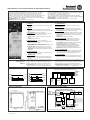
User Interface
A Power Port
Quick-connect spring-clamp terminals, for input voltage and output
voltage.
B Signal Port
Plug connector, inserted from the bottom. Connections for the
Ready, Buffering, Replace Battery relay contacts and for the Inhibit
input.
C Green Status LED (see Fig. 1 for LED pattern)
Ready: Battery is charged, no wiring failure is recognized, input
voltage is sufficient and inhibit signal is not active.
Charging: Battery is charging and the battery capacity is below
85%.
Buffering: Unit is in buffer mode.
D Yellow Diagnosis LED (see Fig. 2 for LED pattern)
Overload: Output has switched off due to long overload in buffer
mode or due to high temperature.
Replace battery: Indicates a battery which failed the battery quality
test (SoH test). Battery should be replaced soon.
Buffer-time expired: Output has switched off due to setting of
Buffer-timer Limiter. This signal will be displayed for 15 minutes.
Inhibit active: Indicates that buffering is disabled due to an active
inhibit signal.
E Red Check Wiring LED
This LED indicates a failure in the wiring, battery, battery fuse or
installation (e.g. too low input voltage).
F Buffer-time Limiter
This dial limits the maximum buffer time during a buffer event to
save the battery energy, for a faster recharge and to expand the
battery life.
Benutzer Schnittstelle
A Leistungsanschlüsse
Federkraftklemmen für die Eingangs- und Ausgangsspannung.
B Signalanschlüsse
Steckverbinder von unten einsteckbar. Anschlüsse für die Ready,
Buffering, Replace Battery Relaiskontakte und für den Inhibit Eingang.
C Grüne „Status“ LED (Blinkmuster ist in Bild 1 erklärt)
Ready: Die DC-USV ist pufferbereit. Batterie ist geladen, kein Inhibit
Signal, kein Verdrahtungsfehler, Eingangsspannung ist ausreichend.
Charging: Die Batterie wird geladen und hat einen Ladezustand von
weniger als 85%.
Buffering: Die DC-USV ist im Pufferbetrieb.
D Gelbe „Diagnosis“ LED (Blinkmuster ist in Bild 2 erklärt)
Overload: Meldet einen abgeschalteten Ausgang, aufgrund von
Überlast während des Pufferbetriebes oder Übertemperatur.
Replace battery: Meldet, wenn die Batterie den Qualitätstest nicht
besteht. Batterie sollte baldmöglichst ersetzt werden.
Buffer-time expired: Meldet einen abgeschalteten Ausgang,
aufgrund von abgelaufener Pufferzeit (Buffer-Time-Limiter). Die
Meldung wird gespeichert und 15 Minuten lang angezeigt.
Inhibit active: Ein aktives Inhibit Signal verhindert eine Pufferung.
E Rote „Check Wiring“ LED
Meldet eine notwendige Überprüfung der Verdrahtung zwischen DC-
USV und Batterie sowie eine notwendige Überprüfung der Batterie
selbst. Meldet auch, wenn die Eingangsspannung zu klein ist.
F “Buffer-time Limiter”
Mit diesem Einstellregler lässt sich die Pufferzeit begrenzen um die
Batterie zu schonen, und eine schnellere Nachladung zu erreichen.
Ready (1-2)
Buffering (2-3)
Replace Battery (5-6)
Inhibit (7-8)
Contact is closed when battery is charged and unit is ready to buffer.
Contact is closed when unit is buffering.
Contact is closed when a replacement of the battery is necessary.
Buffering is disabled when an voltage > 10V is applied to the pins.
Relay contact rating: max. 60Vdc 0.3A, 30Vdc 1A, 30Vac 0.5A
resistive load; min. 1mA at 5Vdc; 500Vac insulated to the power port.
Kontakt ist geschlossen wenn die DC-USV geladen und pufferbereit ist.
Kontakt ist geschlossen wenn das Gerät im Pufferbetrieb ist.
Kontakt ist geschlossen wenn ein Austauschen der Batterie erforderlich ist.
Wenn eine Spannung > 10V anliegt ist eine Pufferung nicht möglich.
Belastbarkeit der Relaiskontakte: max. 60Vdc 0.3A, 30Vdc 1A, 30Vac
0.5A Widerstandslast; min. 1mA bei 5Vdc; isoliert mit 500Vac.
Fig. 1 / Bild 1 Fig. 2 / Bild 2 Fig. 3 / Bild 3
Ready
Charging
Buffering
ON
OFF
ON
OFF
ON
OFF
Overload
Replace
Battery
Buffer time
expired
Inhibit
active
ON
OFF
ON
OFF
ON
OFF
ON
OFF
Wiring diagram / Anschlussdiagram 1606-XLS240-UPSC
24V
unbuffered
branch
24V
Power
supply
+
-
NLPE
DC-UPS
24V
IN
+
-
+
-
24V
buffered
branch
24V
OUT
Buffered
load
+
-
Unbuffered
load
+
-
Dimensions / Abmessungen
Functional Diagram / Funktionsschaltbild
DC-UPS Control unit with integrated battery
Battery Charger
&
Tester
Cut-off
Relay
24V
Power
Supply
Input
-
+
Reverse
Polarity
Protection
Input Fuse
&
*
(5) (6)
Ready
Contact
(1) (2)
Buffering
Contact
(3) (4)
Electronic
Current
Limiter
Buffered
Load
+
-
Output
Controller
Diagnosis LED (yellow)
Check Wiring LED (red)
Status LED (green)
Buffer-time Limiter
10s, 30s, 1m, 3m, 10m,
Inhibit -
Inhibit +
Replace
Battery
Contact
Step-up
Converter
(7)
(8)
12V 5Ah battery
+
-
Fuse
*Return current protection: This feature utilizes a MOSFET instead of a diode to minimize power losses.
PN-22662
PU-357.010.39-10A
Transcripción de documentos
1 2 3 4 5 6 EN DE FR ES IT PT Instruction Manual Bedienungsanleitung Manual d'instructions Manual de instrucciones Manuale di Istruzione Manual de Instruções DC-UPS Uninterruptible Power Supply DC-USV Unterbrechungsfreie Stromversorgung DC-UPS Alimentation sans interruption DC-UPS Fuente de alimentación sin interrupciones DC-UPS Gruppo di continuità DC-UPS Fonte de Alimentação Ininterruptível 1606-XLS240-UPSC Read first ! English 1 Before operating this unit please read this manual thoroughly. Retain this manual for future reference! This device may only installed and put into operation by qualified personnel. Intended Use: This device is designed for installation in an enclosure and is intended for the general use such as in industrial control, office, communication, and instrumentation equipment. Do not use this device in aircrafts, trains and nuclear equipment where malfunction may cause severe personal injury or threaten human life. WARNING ! Risk of electrical shock, fire, personal injury or death. (1) Turn power off before working on the device. Disconnect battery fuse. (2) Make sure if the wiring is correct by following all local and national codes. (3) Do not open, modify or repair the unit. (4) Use caution to prevent any foreign objects from entering into the housing. (5) Do not use in wet locations. (6) Do not use the unit in area where moisture or condensation can be expected. Batteries need to be replaced on a regular basis and when the battery test of the DC-UPS indicates “Replace Battery”. Interval cycles can be found in the DC-UPS datasheet. If damage or malfunction should occur during operation, immediately turn power off and send unit for inspection to the factory! The information presented in this document is believed to be accurate and reliable and may change without notice. The English text applies in cases of doubt. Vor Inbetriebnahme lesen ! Deutsch 2 Bitte lesen Sie diese Warnungen und Hinweise sorgfältig durch bevor Sie das Gerät in Betrieb nehmen. Bewahren Sie die Anleitung zum Nachlesen auf. Das Gerät darf nur durch fachkundiges und qualifiziertes Personal installiert werden. Bestimmungsgemäßer Gebrauch: Dieses Gerät ist für den Einbau in ein Gehäuse konzipiert und zur Verwendung für allgemeine elektronische Geräte, wie z.B. Industriesteuerungen, Bürogeräte, Kommunikationsgeräte oder Messgeräte geeignet. Benutzen Sie dieses Gerät nicht in Steuerungsanlagen von Flugzeugen, Zügen oder atomaren Einrichtungen, in denen eine Funktionsstörung zu schweren Verletzungen führen oder Lebensgefahr bedeuten kann. WARNUNG ! Missachtung nachfolgender Punkte kann einen elektrischen Schlag, Brände, schwere Unfälle oder Tod zur Folge haben. (1) Schalten Sie die Eingangsspannung vor Installations-, Wartungs- oder Änderungsarbeiten ab. Entfernen Sie die Batteriesicherung. (2) Sorgen Sie für eine ordnungsgemäße und fachgerechte Verdrahtung. (3) Führen Sie keine Änderungen oder Reparaturversuche am Gerät durch. Öffnen Sie das Gerät nicht. (4) Verhindern Sie das Eindringen von Fremdkörpern. (5) Betreiben Sie das Gerät nicht in feuchter Umgebung. (6) Betreiben Sie das Gerät nicht in einer Umgebung, bei der mit Betauung oder Kondensation zu rechnen ist. Batterien müssen in regelmäßigen Intervallen erneuert werden. Auch zwischen diesen Intervallen kann ein Batterietausch erforderlich sein, wenn die DC-USV "Replace Battery" signalisiert. Hinweise zur Bestimmung der Intervalle können aus dem DC-USV Datenblatt entnommen werden. Bei Funktionsstörungen oder Beschädigungen schalten Sie sofort die Versorgungsspannung ab und senden das Gerät zur Überprüfung ins Werk. Die angegebenen Daten dienen allein der Produktbeschreibung und sind nicht als zugesicherte Eigenschaften im Rechtssinne aufzufassen. Im Zweifelsfall gilt der englische Text. A lire avant mise sous tension Français 3 Merci de lire ces instructions de montage et d'entretien avant de mettre l'alimentation sous tension. Conservez ce manuel qui vous sera toujours utile. Cette alimentation doit être installée par du personnel qualifié et compétent. Utilisation: Cet appareil est conçu pour être installé dans une armoire et pour tous les équipements électroniques, tel que l'équipement industriel de commande, l'équipement de bureau, le matériel de communication et les instruments de mesures. N'utilisez pas cet appareil pour l'équipement de commandes dans les avions, les trains et l'équipement atomique où un problème de fonctionnement de l'alimentation pourrait causer des blessures graves ou menacer la vie humaine. ATTENTION ! Prendre en compte les points suivants, afin d'éviter toute détérioration électrique, incendie, dommage aux personnes ou mort. (1) ne jamais faire fonctionner l'alimentation sans raccordement à la terre ! Veuillez enlever le fusible de la batterie avant d’effectuer des modifications sur la batterie ou sur le DC-UPS. (2) débrancher l'installation avant toute intervention sur l'alimentation (ou démontage) et s'assurer qu'il n'y a pas risque de redémarrage. (3) s'assurer que le câblage a été fait selon les prescriptions (4) ne pas effectuer de réparations ou modifications sur l'alimentation (5) ne pas ouvrir l'appareil. Des tensions importantes passent à l'intérieur. (6) veiller à ce qu'aucun objet ne rentre en contact avec l'intérieur de l'alimentation (trombones, pièces métalliques) (7) ne pas faire fonctionner l'appareil dans un environnement humide ou à l'extérieur, non protégé (8) ne pas utiliser l'appareil dans un environnement où il peut y avoir de la condensation. Les batteries doivent être remplacées à intervalles réguliers. Il est cependant possible qu’un remplacement de batterie soit nécessaire entre ces intervalles, si DC-UPS indique ‘Replace Battery’. Vous trouverez les intervalles conseillés dans la fiche technique du DC-UPS. Si un défaut quelconque apparaît en cours de fonctionnement, débrancher au plus vite l'alimentation. Dans ce deux cas de figure, il convient de faire contrôler l'alimentation en usine! Les données indiquées dans ce document servent uniquement à donner une description du produit et n'ont aucune valeur juridique. En cas de divergences, le texte anglais fait foi. Lea primero! Español 4 Conserve este manual como referencia para futuras consultas. La fuente de alimentación solo puede ser instalada y puesta en funcionamiento por personal cualificado. Por favor lea detenidamente este manual antes de conectar la fuente de alimentación. Uso apropiado: Este equipo ha sido diseñado para su instalación en un ambiente cerrado y ha sido concebido para uso general en instalaciones de control industrial, oficinas, comunicaciones y equipos de instrumentación. No emplee este equipo en aeronaves, trenes e instalaciones atómicas, donde un mal funcionamiento de la fuente de alimentación puede ocasionar lesiones graves o riesgo mortal. ADVERTENCIA ! Riesgo de descarga eléctrica, incendio, accidente grave o muerte. (1) No conectar nunca la unidad sin conexión de puesta a tierra. Desconecte el fusible de la batería antes de manipular la batería o el DC-UPS. (2) Desconectar la tensión de red antes de trabajar en la fuente de alimentación. Evite una posible reconexión involuntaria. (3) Asegurarse de que el cableado es correcto de acuerdo a los códigos locales y nacionales. (4) No realizar ninguna modificación o reparación de la unidad. (5) No abrir nunca la unidad. En el interior existe riesgo de altas tensiones. (6) Evitar la introducción en la carcasa de objetos extraños. (7) No usar el equipo en ambientes húmedos. (8) No operar el equipo en ambientes donde se espere la formación de rocío o condensación. Las baterías se deben reemplazar regularmente y cuando el test de baterías del DC-UPS indique cambio de batería “Replace Battery”. Los ciclos de mantenimiento de las baterías se pueden encontrar en las hojas técnicas del DC-UPS. Si se produce un fallo o mal funcionamiento durante la operación, desconecte inmediatamente la tensión de alimentación. En ambos casos, el equipo debe ser inspeccionado en fábrica. La información presentada en este documento es exacta y fiable en cuanto a la descripción del producto y puede cambiar sin aviso. En casa de duda, prevalece el texto inglés. Leggere prima questa parte! Italiano 5 Prima di collegare il sistema di alimentazione elettrica si prega di leggere attentamente le seguenti avvertenze. Conservare le istruzioni per la consultazione futura. Il sistema di alimentazione elettrica deve essere installato solo da personale competente e qualificato. Uso previsto: Questo apparecchio è previsto per il montaggio in un rack per moduli elettronici, ad esempio per controllori industriali, apparecchiature per ufficio, unità di comunicazione o apparecchi di misura. Non utilizzare l'apparecchio in impianti di controllo di aerei, di treni o di impianti nucleari in cui il suo eventuale guasto può comportare gravi lesioni o la morte di persone. AVVERTENZA! Il mancato rispetto delle seguenti norme può provocare folgorazione elettrica, incendi, gravi incidenti e perfino la morte. (1) Non far funzionare in nessun caso il sistema di alimentazione elettrica senza conduttore di protezione! Disconnettere il fusibile della batteria prima di agire sulla batteria o sull' DC-UPS. (2) Prima di eseguire interventi di installazione, di manutenzione o di modifica scollegare la tensione di rete ed adottare tutti i provvedimenti necessari per impedirne il ricollegamento non intenzionale. (3) Assicurare un cablaggio regolare e corretto. (4) Non tentare di modificare o di riparare da soli l'apparecchio. (5) Non aprire l'apparecchio. Al suo interno sono applicate tensioni elettriche pericolose. (6) Impedire la penetrazione di corpi estranei nell'apparecchio, ad esempio fermagli o altri oggetti metallici. (7) Non far funzionare l'apparecchio in un ambiente umido. (8) Non far funzionare l'apparecchio in un ambiente soggetto alla formazione di condensa o di rugiada. E' necessario sostituire le batterie con regolarità e quando il test sul DC-UPS indica "Replace Battery". I cicli d'intervallo si trovano sul data sheet del DC-UPS. Se durante il funzionamento si verificano anomalie o guasti, scollegare immediatamente la tensione di alimentazione. In entrambi i casi è necessario far controllare l'apparecchio dal produttore! I dati sono indicati solo a scopo descrittivo del prodotto e non vanno considerati come caratteristiche garantite dell'apparecchio.In caso di differenze o problemi è valido il testo inglese Leia primeiro! Portuguès 6 Recomendamos a leitura cuidadosa das seguintes advertências e observações, antes de colocar em funcionamento a fonte de alimentação. Guarde as Instruções para futura consulta, em casos de dúvida. A fonte de alimentação deverá ser instalada apenas por profissionais da área, tecnicamente qualificados. Utilize: apenas para o fim pré-estabelecido. Este aparelho foi concebido para ser montado dentro de invólucros, caixas ou armários para aparelhos eletrônicos em geral, como, por exemplo, comandos de instalações industriais, aparelhos para escritórios, aparelhos de comunicação ou instrumentos de medida e quadros eléctricos. Não utilize este aparelho em sistemas de comando de aviões, de comboios ou em instalações movidas por energia nuclear, nos quais um defeito de funcionamento poderá causar danos graves ou significar risco de morte. ATENÇÃO ! A não observância ou o incumprimento dos pontos a seguir mencionados, poderá causar uma descarga elétrica, incêndios, acidentes graves ou morte. (1) Não use a fonte de alimentação sem o condutor de proteção terra! Desligar o fusível antes de mexer; na bateria ou na fonte DC-UPS. (2) Antes de trabalhos de instalação, manutenção ou modificação, desligue a tensão de alimentação, protegendo-a contra uma nova ligação involuntária. (3) As ligações devem ser efectuadas apenas por profissionais competentes. (4) Não efectue nenhuma modificação ou tentativa de reparação no aparelho. Quando necessário contacte o seu distribuidor. (5) Não abra o aparelho mesmo quando desligado. No seu interior existem condensadores que podem estar carregados electricamente. (6) Proteger a fonte de alimentação contra a introdução inadvertida de corpos metálicos, como por ex., clipes ou outras peças de metal. (7) Não usar o aparelho em ambientes húmidos. (8) Não usar o aparelho em ambientes propensos a condensações. A bateria necessita ser substituída, por outrsa nova, sempre que o DC-UPS indicar “Replace Battery”. O intervalo de tempo para substituição da mesma pode ser encontrado nas características técnicas. Se por acaso, durante a utilização ocorrer algum defeito de funcionamento ou dano, desligue imediatamente a tensão de alimentação. Em ambos os casos, será necessária uma verificação na Fábrica! Os dados mencionados têm como finalidade somente a descrição do produto, e não devem ser interpretados como propriedades garantidas no sentido jurídico. Em caso de duvidas aplica-se o texto em inglês. Rev.: 03/2008 © 2008 by Allen-Bradley Company, LCC Industrial Components Business 1201 South Second Street Milwaukee, WI 53204-2496 USA Phone 440 646 5800 Rockwell Automation CH-5001 Aarau, Switzerland Fax +41 62 837 2202 1606-XLS240-UPSC DC-UPS Instruction Manual / DC-USV Bedienungsanleitung General Description Gerätebeschreibung: The 1606-XLS240-UPSC offers DIN-rail DC-UPS which bridge power outages for minutes by utilizing only one 12V battery for a 24V output. The 1606-XLS240-UPSC has one integrated 5Ah high-current battery. Das 1606-XLS240-UPSC dient zur Überbrückung von Netzausfällen im Minutenbereich, hierfür wird nur eine 12V Batterie benötigt. Das 1606-XLS240-UPSC hat eine integrierte 5Ah Hochstrombatterie. Technical Data 1) Technische Daten 1) Output Voltage Output Current Ausgangsspannung Ausgangsstrom Output Power Ausgangsleistung 1606-XLS240-UPSC 22.25V 3) 15A nom. 10/ 15A 4) 240/ 360W 5) nom. Input Voltage Eingangsspannung Input Voltage Range Eingangsspannungsbereich Transfer Threshold Buffer Mode Umschaltschwelle Pufferbetrieb Allowed Batteries Allowed Battery Capacity Erlaubte Batterien Erlaubte Batteriekapazität Integrated Battery Integrierte Batterie Dimensions (wxhxd) Type of Terminals Batterie Abmessungen (BxHxT) Anschlüsse Power Losses Verlustleistung Operational Temperature Storage Temp. Range Betriebstemperatur Lagertemperaturbereich 2) nom. DC 24V 22.5 – 30Vdc 22.25V nom. 12V, VRLA 5Ah 5Ah high-current / Hochstromtyp nom 90x106x70mm6) Blade-type 250/ Flachstecker für 6.35mm Steckhülse typ. 2.9/5.5W 7) 0 - +40°C -20 - +50°C Humidity Feuchte IEC60068-2-30 5 - 95% r.H. 8) Vibration Shock Schwingen Schocken IEC 60068-2-6 1g 9) 15g 6ms, 10g 11ms 9) Degree of Pollution Degree of Protection Over-temp. Protection Verschmutzungsgrad Schutzart Übertemperaturschutz Parallel Use Serial Use Parallelschaltbar Serienschaltbar Dimensions (wxhxd) Weight Abmessungen (BxHxT) Gewicht Approvals Zulassungen IEC60068-2-27 EN 50078 EN 60529 2 IP20 Yes / Ja 10) No / Nein No / Nein nom. max. 123x124x119mm 11) 2850g / 6.28lb 12) 1) All parameters are specified at 24Vdc input voltage, nominal output current, 25°C ambient and after a 5 minutes run-in time unless otherwise noted. The output voltage is regulated to 22.25Vdc in a buffer event. In all other cases, the output voltage is approx. 0.3V lower than the input voltage assuming that the input voltage is sufficient and no overload is present. 3) When no buffer event is present. 4) During a buffer event 15A is available for the first 5 seconds. After this time, the output current is limited to 10A. 5) The allowed output power is 360W when no buffer event is present as well as for the first 5 seconds during a buffer event. After this, the allowed output power is 240W. 6) Battery container height without terminals: 102mm 7) At no load / 10A load, no buffer event is present. 8) Do not energize while condensation is present. 9) Use wall mounting accessory for higher values. 10) Output shuts down with automatic restart. 11) Depth without DIN-rail. 12) See datasheet or markings on the unit. 1) 2) 2) Installation Procedure Installationsanleitung: 1. Use DIN-rails according to EN 60715 or EN 50022 with a height of 15mm. The unit is convection cooled. Do not obstruct air flow! Ventilation grid must be kept free of any obstructions. 2. Connect the power supply to the input terminals of the DC-UPS. 3. Disconnect the fuse on the front of the DC-UPS before working on the unit or on the battery. 4. Connect the buffered load to the output terminals of the DC-UPS. The output is decoupled from the input allowing load circuits to be easily split into buffered and non buffered sections. Noncritical loads can be connected directly to the power supply and will not be buffered. The energy in the battery will be used in the circuits which require buffering. 5. Set the buffer time limiter to an appropriate value. 6. Install the fuse when the wiring is finished. Red LED on the DC-UPS should turn off. 1. Geeignet zur Montage an DIN-Schienen entsprechend EN 60715 oder EN 50022 mit einer Höhe von 15mm. Das Gerät ist für Konvektionskühlung ausgelegt. Es ist für eine ungehinderte Luftzirkulation zu sorgen. 2. Schließen Sie die Stromversorgung and die “Input” Klemmen der DC-USV an. 3. Ziehen Sie die Sicherung an der Front des Gerätes heraus, bevor Sie die Batterie anschließen oder Installationsarbeiten durchführen. 4. Schließen Sie die zu puffernde Last an die „Output“ Klemmen an. Der Ausgang ist vom Eingang entkoppelt. So kann man Lasten in gepufferte und ungepufferte Zweige aufteilen. Unkritische Lasten können ungepuffert direkt an die Stromversorgung angeschlossen werden. So wird die Energie der Batterie nur für zu puffernde Lasten verwendet. 5. Stellen Sie am "Buffer-Time-Limiter" Einsteller (Pufferzeit-Begrenzer) den entsprechenden Wert ein. 6. Stecken Sie die Sicherung ein, wenn alle Arbeiten an der Batterie oder DC-USV beendet sind. Nach dem Einschalten muss die rote LED erlöschen. Terminals and Wiring The units are equipped with spring-clamp terminals for the power port and with a plug connector for the signal port. Use appropriate copper cables that are designed for an operating temperatures of 60°C (for ambient up to 45°C) and 75°C (for ambient up to 60°C), minimum. Follow national installation codes and regulations! Ensure that all strands of a stranded wire enter the terminal connection! Ferrules are allowed, but not required. Power terminals: Solid wire / Stranded wire / American wire gauge: 0.5-6mm2 / 0.5-4mm2 / 20-10 AWG Wire stripping length: 10mm / 0.4inch Pull-out force (UL 486E): 10AWG: 80N, 12AWG: 60N Signal terminals: Solid wire / Stranded wire / American wire gauge: 0.2-1.5mm2 / 0.2-1.5mm2 / 22-14 AWG Wire stripping length: 6mm / 0.25inch Recommended tightening torque: 0.4Nm / 3.5lb.inch Alle Werte gelten bei 24Vdc Eingangsspannung, Nennausgangsstrom, 25°C Umgebung und nach einer Aufwärmzeit von 5 Minuten, wenn nichts anderes angegeben ist. Während eines Pufferfalls ist die Ausgangsspannung auf 22.25V geregelt. In allen anderen Fällen ist die Ausgangsspannung etwa 0,3V kleiner als die Eingangsspannung vorausgesetzt, dass die Eingangsspannung im spez. Bereich ist und kein Überlastfall vorliegt. 3) Wenn kein Pufferfall vorliegt. 4) Während eines Pufferfalls stehen für die ersten 5 Sekunden 15A zur Verfügung. Danach ist der Ausgangsstrom auf 10A begrenzt. 5) Die erlaubte Ausgangsleistung ist 360W wenn kein Pufferfall besteht oder während der ersten 5 Sekunden eines Pufferfalls. Danach ist die erlaubte Ausgangsleistung 240W. 6) Batterie-Gehäuse Höhe ohne Anschlüsse: 102mm 7) Bei Leerlauf / 10A Last und wenn kein Pufferfall besteht. 8) Nicht betreiben, solange das Gerät Kondensation aufweist. 9) Mit Wandmontage-Zubehör höhere Werte erreichbar. 10) Ausgang schaltet ab und macht regelmäßig automatische Startversuche. 11) Tiefe ohne DIN-Schiene. 12) Siehe Datenblatt oder Prüfzeichen auf dem Gerät. Anschlussklemmen und Verdrahtung Die Geräte sind mit Schnellanschluss-Federkraftklemmen ausgestattet. Verwenden Sie geeignete Kupferkabel, die mindestens für 60°C (bei einer Umgebungstemperatur bis zu 45°C) und 75°C (bei einer Umgebungstemperatur bis zu 60°C) zugelassen sind. Beachten Sie nationale Bestimmungen und Installationsvorschriften! Stellen Sie sicher, dass keine einzelnen Drähte von Litzen abstehen. Aderendhülsen sind erlaubt, aber nicht erforderlich. Leistungsanschlussklemmen: Starrdraht / Litze / Amerikanischer Querschnitt: 0,5-6mm2 / 0,5-4mm2 / 20-10 AWG Abisolierlänge: 10mm / 0,4inch Abziehkraft (UL 486E): 10AWG: 80N, 12AWG: 60N Signalklemmen: Starrdraht / Litze / Amerikanischer Querschnitt: 0,2-1,5mm2 / 0,2-1,5mm2 / 22-14 AWG Abisolierlänge: 6mm / 0,25inch Empfohlenes Anzugsdrehmoment: 0,4Nm / 3.5lb.inch 1606-XLS240-UPSC DC-UPS Instruction Manual / DC-USV Bedienungsanleitung EMC Electromagnetic Compatibility EMV Elektromagnetische Verträglichkeit These devices are suitable for applications in industrial environment as well as in residential, commercial and light industry environment. These devices comply with FCC Part 15 rules. Operation is subjected to following two conditions: (1) this device may not cause harmful interference, and (2) this device must accept any interference received, including interference that may cause undesired operation. CE mark is in conformance with EMC directive 89/336/EC, 93/68/EC and 2004/108/EC and the low-voltage directive (LVD) 73/23/EC, 93/68/EC, 2006/95/EC. EMC Immunity: EN 61000-6-1, EN 61000-6-2 EMC Emission: EN 61000-6-3, EN 61000-6-4, FCC Part 15 Class B Diese Geräte erfüllen die Anforderungen für Anwendungen sowohl in industrieller Umgebung als auch für den Wohn-, Geschäfts- und Gewerbebereich. Die Geräte erfüllen auch die Anforderungen der FCC Teil 15. Das CE Zeichen ist angebracht und erklärt die Erfüllung der EMV Richtlinien 89/336/EG, 93/68/EG, 2004/108/EG und der Niederspannungsrichtlinien 73/23/EG, 93/68/EG, 2006/95/EG. EMV Störfestigkeit: EN 61000-6-1, EN 61000-6-2 EMV Störaussendung: EN 61000-6-3, EN 61000-6-4, FCC Part 15 Klasse B User Interface Benutzer Schnittstelle A Power Port A Leistungsanschlüsse Federkraftklemmen für die Eingangs- und Ausgangsspannung. Quick-connect spring-clamp terminals, for input voltage and output voltage. B Signalanschlüsse B Signal Port Steckverbinder von unten einsteckbar. Anschlüsse für die Ready, Buffering, Replace Battery Relaiskontakte und für den Inhibit Eingang. Plug connector, inserted from the bottom. Connections for the Ready, Buffering, Replace Battery relay contacts and for the Inhibit input. Ready: Die DC-USV ist pufferbereit. Batterie ist geladen, kein Inhibit Signal, kein Verdrahtungsfehler, Eingangsspannung ist ausreichend. Ready: Battery is charged, no wiring failure is recognized, input voltage is sufficient and inhibit signal is not active. Charging: Die Batterie wird geladen und hat einen Ladezustand von weniger als 85%. Charging: Battery is charging and the battery capacity is below 85%. Buffering: Die DC-USV ist im Pufferbetrieb. D Gelbe „Diagnosis“ LED (Blinkmuster ist in Bild 2 erklärt) Buffering: Unit is in buffer mode. Overload: Meldet einen abgeschalteten Ausgang, aufgrund von Überlast während des Pufferbetriebes oder Übertemperatur. D Yellow Diagnosis LED (see Fig. 2 for LED pattern) Overload: Output has switched off due to long overload in buffer mode or due to high temperature. Replace battery: Meldet, wenn die Batterie den Qualitätstest nicht besteht. Batterie sollte baldmöglichst ersetzt werden. Replace battery: Indicates a battery which failed the battery quality test (SoH test). Battery should be replaced soon. Buffer-time expired: Meldet einen abgeschalteten Ausgang, aufgrund von abgelaufener Pufferzeit (Buffer-Time-Limiter). Die Meldung wird gespeichert und 15 Minuten lang angezeigt. Buffer-time expired: Output has switched off due to setting of Buffer-timer Limiter. This signal will be displayed for 15 minutes. Inhibit active: Ein aktives Inhibit Signal verhindert eine Pufferung. Inhibit active: Indicates that buffering is disabled due to an active inhibit signal. E This LED indicates a failure in the wiring, battery, battery fuse or installation (e.g. too low input voltage). F “Buffer-time Limiter” F Buffer-time Limiter Mit diesem Einstellregler lässt sich die Pufferzeit begrenzen um die Batterie zu schonen, und eine schnellere Nachladung zu erreichen. This dial limits the maximum buffer time during a buffer event to save the battery energy, for a faster recharge and to expand the battery life. Contact is closed when battery is charged and unit is ready to buffer. Contact is closed when unit is buffering. Contact is closed when a replacement of the battery is necessary. Buffering is disabled when an voltage > 10V is applied to the pins. Relay contact rating: max. 60Vdc 0.3A, 30Vdc 1A, 30Vac 0.5A resistive load; min. 1mA at 5Vdc; 500Vac insulated to the power port. Fig. 1 / Bild 1 Rote „Check Wiring“ LED Meldet eine notwendige Überprüfung der Verdrahtung zwischen DCUSV und Batterie sowie eine notwendige Überprüfung der Batterie selbst. Meldet auch, wenn die Eingangsspannung zu klein ist. E Red Check Wiring LED Ready (1-2) Buffering (2-3) Replace Battery (5-6) Inhibit (7-8) (Blinkmuster ist in Bild 1 erklärt) C Grüne „Status“ LED C Green Status LED (see Fig. 1 for LED pattern) Kontakt ist geschlossen wenn die DC-USV geladen und pufferbereit ist. Kontakt ist geschlossen wenn das Gerät im Pufferbetrieb ist. Kontakt ist geschlossen wenn ein Austauschen der Batterie erforderlich ist. Wenn eine Spannung > 10V anliegt ist eine Pufferung nicht möglich. Belastbarkeit der Relaiskontakte: max. 60Vdc 0.3A, 30Vdc 1A, 30Vac 0.5A Widerstandslast; min. 1mA bei 5Vdc; isoliert mit 500Vac. Fig. 2 / Bild 2 Fig. 3 / Bild 3 Wiring diagram / Anschlussdiagram 1606-XLS240-UPSC 24V unbuffered branch ON OFF Buffer time expired ON OFF Inhibit active 24V buffered branch - 24V Power supply N Dimensions / Abmessungen - - 24V 24V IN OUT - - + Buffering Replace Battery + Charging ON OFF Overload ON OFF + ON OFF ON OFF + Ready + ON OFF Unbuffered load Buffered load DC-UPS L PE Functional Diagram / Funktionsschaltbild DC-UPS Control unit with integrated battery + 24V Power Supply Input - Input Fuse & Reverse Polarity Protection + Electronic Current Limiter * Output Buffered Load Step-up Converter Battery Charger & Tester Status LED (green) Diagnosis LED (yellow) Controller Buffer-time Limiter 10s, 30s, 1m, 3m, 10m, + 12V 5Ah battery - Check Wiring LED (red) Cut-off Relay (7) (8) (1) Fuse (2) (3) (4) (5) Inhibit + Inhibit - (6) Ready Buffering Replace Contact Contact Battery Contact *Return current protection: This feature utilizes a MOSFET instead of a diode to minimize power losses. PN-22662 PU-357.010.39-10A-
 1
1
-
 2
2
-
 3
3
-
 4
4


Rockwell Automation 1606-XLS240-UPSC Manual de usuario
- Tipo
- Manual de usuario
en otros idiomas
Artículos relacionados

Otros documentos
-
Puls UB40.241 DIN Rail Controller Manual de usuario
-
-
Pepperl+Fuchs PS1000-D2-24.10 Manual de usuario
-
-
Tripp Lite SMX700HGL El manual del propietario
-
-
-
Tripp Lite S3M60KX El manual del propietario
-
BlueWalker PowerWalker VFI 1000 LCD Especificación