La página se está cargando...

Headquarters: PULS GmbH, Elektrastr. 6, 81925 Munich, Germany, www.pulspower.com
Germany +49 89 9278 0
China +86 512 62881820
France +33 478 668 941
North America +1 630 587 9780
Austria +43 2764 3213
Singapore +65 6684 2310
Switzerland +41 56 450 18 10
United Kingdom +44 1525 841001
The information in this document is believed to be accurate and reliable and may change without notice.
EN
UB40.241 Installation Manual
DC-UPS Control Unit 24V, 40A, 960W
DE
UB40.241 Installationsanleitung
DC-USV Steuergerät 24V, 40A, 960W
FR
UB40.241 Manuel d'installation
Sauvegarde CC 24V, 40A, 960W
ES
UB40.241 Manual de instalación
Unidad de control SAI en CC 24V, 40A, 960W
IT
UB40.241 Manuale di Installazione
Unità di controllo UPS in CC 24V, 40A, 960W
PT
UB40.241 Manual de instalação
Unidade de controle UPS em CC 24V, 40A, 960W
Doc. ID: PU-394.015.00-xxD (2022-04-22-MK3)
Read this first!
English
Vor Inbetriebnahme lesen!
Deutsch
Before operating this device, please read this manual thoroughly and retain this manual for
future reference! This device may only be installed and put into operation by qualified
personnel. If damage or malfunction should occur during operation, immediately turn power
off and send device to the factory for inspection. The device does not contain serviceable
parts. The information presented in this document is believed to be accurate and reliable and
may change without notice. For any clarifications the English translation will be used.
Bitte lesen Sie diese Warnungen und Hinweise sorgfältig durch, bevor Sie das Gerät in Betrieb
nehmen. Bewahren Sie die Anleitung zum Nachlesen auf. Das Gerät darf nur durch
fachkundiges und qualifiziertes Personal installiert werden. Bei Funktionsstörungen oder
Beschädigungen schalten Sie sofort die Versorgungsspannung ab und senden das Gerät zur
Überprüfung ins Werk. Das Gerät beinhaltet keine Servicebauteile. Die angegebenen Daten
dienen allein der Produktbeschreibung und sind nicht als zugesicherte Eigenschaften im
Rechtssinne aufzufassen. Im Zweifelsfall gilt der englische Text.
WARNING
Risk of electrical shock, fire, personal injury, or death:
WARNUNG
Missachtung nachfolgender Punkte kann einen elektrischen
Schlag, Brände, schwere Unfälle oder Tod zur Folge haben:
- Turn power off before working on the device. Protect against inadvertent re-powering.
- Do not open, modify or repair the device.
- Use caution to prevent any foreign objects from entering the housing.
- Do not use in wet locations or in areas where moisture or condensation can be expected.
- Do not touch during power-on and immediately after power-off. Hot surfaces may cause
burns.
- Schalten Sie die Eingangsspannung vor Installations-, Wartungs- oder Änderungsarbeiten
ab und sichern Sie diese gegen unbeabsichtigtes Wiedereinschalten.
- Führen Sie keine Änderungen oder Reparaturversuche am Gerät durch. Gerät nicht öffnen!
- Verhindern Sie das Eindringen von Fremdkörpern, wie z.B. Büroklammern und Metallteilen.
- Betreiben Sie das Gerät nicht in feuchter Umgebung oder in einer Umgebung, bei der mit
Betauung oder Kondensation zu rechnen ist.
- Gehäuse nicht während des Betriebes oder kurz nach dem Abschalten berühren. Heiße
Oberflächen können Verletzungen verursachen.
A lire avant mise sous tension!
Français
Lea primero!
Español
Veuillez lire ces instructions de montage et d'entretien avant de mettre l'alimentation sous
tension. Conservez ce manuel qui vous sera toujours utile. Cette alimentation ne doit être
installée que par du personnel qualifié et compétent. En cas de dommage ou
dysfonctionnement, coupez immédiatement la tension d’alimentation et retournez l’appareil à
l’usine pour vérification. ! L’alimentation ne contient pas de pièces échangeables Les
données indiquées dans ce document servent uniquement à donner une description du
produit et n'ont aucune valeur juridique. En cas de divergences, le texte anglais fait foi.
Conserve este manual como referencia para futuras consultas. La fuente de alimentación solo
puede ser instalada y puesta en funcionamiento por personal cualificado. Por favor lea
detenidamente este manual antes de conectar la fuente de alimentación. Si se produce un fallo
o mal funcionamiento durante la operación, desconecte inmediatamente la tensión de
alimentación. En ambos casos, el equipo debe ser inspeccionado en fábrica. La información
presentada en este documento es exacta y fiable en cuanto a la descripción del producto y
puede cambiar sin aviso. En casa de duda, prevalece el texto inglés.
AVERTISSEMENT
Prendre en compte les points suivants, afin
d'éviter toute détérioration électrique, incendie,
dommage aux personnes ou mort:
ADVERTENCI A
Riesgo de descarga eléctrica, incendio, accidente
grave o muerte:
- Mettre l’alimentation hors tension avant toute intervention sur celle-ci et s'assurer qu'il n'y
a pas risque de redémarrage.
- Ne pas ouvrir, modifier ou réparer l'alimentation.
- Veiller à ce qu'aucun objet ne rentre en contact avec l'intérieur de l'alimentation
(trombones, pièces métalliques).
- Ne pas faire fonctionner l'appareil dans un environnement humide ou dans un
environnement où il peut y avoir de la condensation.
- Ne pas toucher le carter pendant le fonctionnement ou directement après la mise hors
tension. Surface chaude risquant d’entraîner des blessures.
- Desconectar la tensión de red antes de trabajar en la fuente de alimentación. Evite una
posible reconexión involuntaria.
- No realizar ninguna modificación o reparación de la unidad. No abrir la unidad.
- Evitar la introducción en la carcasa de objetos extraños.
- No usar el equipo en ambientes húmedos. No operar el equipo en ambientes donde se
espere la formación de rocío o condensación.
- No tocar durante el funcionamiento ni inmediatamente después del apagado. El calor de la
superficie puede causar quemaduras graves.
Leggere prima questa parte!
Italiano
Leia primeiro!
Portuguès
Prima di collegare il sistema di alimentazione elettrica si prega di leggere attentamente le
seguenti avvertenze. Conservare le istruzioni per la consultazione futura. Il sistema di
alimentazione elettrica deve essere installato solo da personale competente e qualificato. Se
durante il funzionamento si verificano anomalie o guasti, scollegare immediatamente la
tensione di alimentazione. In entrambi i casi è necessario far controllare l'apparecchio dal
produttore! I dati sono indicati solo a scopo descrittivo del prodotto e non vanno considerati
come caratteristiche garantite dell'apparecchio. In caso di differenze o problemi è valido il
testo inglese
Recomendamos a leitura cuidadosa das seguintes advertências e observações, antes de
colocar em funcionamento a fonte de alimentação. Guarde as Instruções para futura consulta,
em casos de dúvida. A fonte de alimentação deverá ser instalada apenas por profissionais da
área, tecnicamente qualificados. Se por acaso, durante a utilização ocorrer algum defeito de
funcionamento ou dano, desligue imediatamente a tensão de alimentação. Em ambos os casos,
será necessária uma verificação na Fábrica! Os dados mencionados têm como finalidade
somente a descrição do produto, e não devem ser interpretados como propriedades garantidas
no sentido jurídico. Em caso de duvidas aplica-se o texto em inglês.
AVVERTENZA
Il mancato rispetto delle seguenti norme può
provocare folgorazione elettrica, incendi, gravi
incidenti e perfino la morte:
ATENÇÃO
A não observância ou o incumprimento dos pontos a seguir
mencionados, poderá causar uma descarga elétrica, incêndios,
acidentes graves ou morte:
- Prima di eseguire interventi di installazione, di manutenzione o di modifica scollegare la
tensione di rete ed adottare tutti i provvedimenti necessari per impedirne il ricollegamento
non intenzionale.
- Non tentare di aprire, di modificare o di riparare da soli l'apparecchio.
- Impedire la penetrazione di corpi estranei nell'apparecchio, ad esempio fermagli o altri
oggetti metallici.
- Non far funzionare l'apparecchio in un ambiente umido. Non far funzionare l'apparecchio
in un ambiente soggetto alla formazione di condensa o di rugiada.
- Non toccare quando acceso e subito dopo lo spegnimento. La superficie calda può
causare scottature.
- Antes de trabalhos de instalação, manutenção ou modificação, desligue a tensão de
alimentação, protegendo-a contra uma nova ligação involuntária.
- Não efectue nenhuma modificação ou tentativa de reparação no aparelho. Quando
necessário contacte o seu distribuidor. Não abra o aparelho.
- Proteger a fonte de alimentação contra a introdução inadvertida de corpos metálicos, como
por ex., clipes ou outras peças de metal.
- Não usar o aparelho em ambientes húmidos. Não usar o aparelho em ambientes propensos
a condensações.
- Não tocar enquanto estiver em funcionamento, nem após a desligar. A superficie poderá
estar quente e provocar lesões.
.
.
.
.
.
.
.
.
.
.
.
.
.
.
.
.
.
.

EN
UB40.241 Installation Manual
Product Description
The UB40.241 is an uninterruptible power supply controller (DC-UPS), which is used in combination
with a 24V power supply and one external 24V-battery pack to bridge power failures. The controller
can be used with any type of SELV power supply as long as the maximum output current ratings of the
UB40.241 are not exceeded. When the power supply provides sufficient voltages, the DC-UPS
controller charges the battery. When the power supply voltage fails, the energy stored in the battery is
released to the DC bus in a regulated process.
Intended Use
This device is designed for installation in an enclosure and is intended for commercial use, such as in
industrial control, process control, monitoring and measurement equipment or the like.
Do not use this device in equipment, where malfunctioning may cause severe personal injury or
threaten human life without additional appropriate safety devices, that are suited for the end-
application.
If this device is used in a manner outside of its specification, the protection provided by the device may
be impaired.
Installation Instructions
Turn power off and disconnect the battery fuse before working on the device.
Install the device in an enclosure providing protection against electrical, mechanical and fire hazards.
Install the device onto a DIN rail according to EN 60715 with the battery terminals on the bottom of the
unit.
The input can be powered from a regulated power supply or a similar DC source. Use an appropriately
sized power supply, which can deliver the additionally required internal current consumption of the DC-
UPS and the required current for charging the batteries. If a power supply with a continuous output
current greater than 50A is used, a fuse with 63A B- or C-Characteristic must be connected between
the power supply and the DC-UPS. The continuous voltage between the input and ground must not
exceed 60Vdc. The input must be powered from a PELV or SELV source or an “SELV or PELV
isolated secondary circuit” in order to maintain a SELV or PELV output. Check for correct input and
battery polarity. The device will not operate when the voltage is reversed.
Use only VRLA lead acid batteries with a capacity between 12Ah and 200Ah.
Make sure that the wiring is correct by following all local and national codes. Use appropriate copper
cables that are designed for a minimum operating temperature of 60°C for ambient temperatures up to
+45°C, 75°C for ambient temperatures up to +60°C and 90°C for ambient temperatures up to +70°C.
Ensure that all strands of a stranded wire enter the terminal connection.
Do not use wires smaller than 6mm2 (AWG 10) and not longer than 2x1m between the power supply
and the DC-UPS controller. Longer or smaller gauge wires can cause malfunctioning of the system.
Do not use wires smaller than 6mm2 (AWG 10) and not longer than 2x1.5m between the battery and
the DC-UPS controller. Longer or smaller gauge wires can change performance of the system.
Use two fuses each 35A or 40A in parallel (ATOF® 287 035 or ATOF® 287 040 from Littelfuse or an
UL listed fuse with the same characteristics) in the battery circuit. The battery fuse protects the wires
between the battery and the DC-UPS and shall be located close to the battery.
The device is designed for pollution degree 2 areas in controlled environments. No condensation or
frost is allowed.
The device is suitable for indoor applications. Outdoor applications are also allowed as long as the
device is installed in a control cabinet that fulfills all requirements specified in this installation manual
(controlled environment, condensation, ...).
The device is designed as “Class of Protection III” equipment according to IEC 61140.
The enclosure of the device provides a degree of protection of IP20. The enclosure does not provide
protection against spilled liquids.
The isolation of the devices is designed to withstand impulse voltages up to 1.5kV according to IEC
60664-1.
A disconnecting means shall be provided for the input and the battery input of the device.
The device is designed for convection cooling and does not require an external fan. Do not obstruct
airflow and do not cover ventilation grid!
Keep the following minimum installation clearances: 40mm on top, 20mm on the bottom, 5mm left and
right side. Increase the 5mm to 15mm in case the adjacent device is a heat source. When the device
is permanently loaded with less than 50%, the 5mm can be reduced to zero.
The device is designed for altitudes up to 5000m (16400ft). Above 2000m (6560ft) a reduction in
output current is required.
The maximum surrounding air temperature is +70°C (+158°F). The operational temperature is the
same as the ambient or surrounding air temperature and is defined 2cm below the device.
The device is designed to operate in areas between 5% and 95% relative humidity.
Use a 4A fuse (ATOF® 287 004 from Littelfuse or an UL listed fuse with same characteristics) between
the connection point of the two 12V batteries and the “Center Tap” connection point of the DC-UPS.
An equivalent protection is included on the original battery modules. The center tap connection is not
mandatory but enables an individual charging and monitoring of the two batteries.
Optionally, a PT1000 temperature sensor can be connected to terminals point 11 and 12 to measure
the battery temperature. This adjusts the charging voltage according to the battery temperature which
extends the battery life. This sensor is already installed in the original battery modules.
Technical Data
All values are typical figures specified at 24Vdc input voltage, 40A output
current in power supply mode at 25°C ambient, no charging and after a 5
minutes run-in time unless otherwise noted.
Input voltage
DC 24V
±25%
Min. input voltage to start
charging and to enable
battery mode
23V
Transfer voltage to switch
into battery mode
22.2V
Internal current
consumption
3.2A / 6.2A
<65Ah / ≥65Ah, includes
charging current
Voltage loss
55mV / 110mV
Input to output at 20A /
40A
110mV / 220mV
Battery input to output at
20A / 40A
Output current
50A
Below +50°C
40A
At +60°C
30A
At +70°C
60A
Short term, up to 5s
Derate between +50°C and +70°C
Power losses
6.0W
At 40A in power supply
mode, full batteries
9.9W
At 40A in battery mode
Temperature range
-25°C to +70°C
Max. wire size (litz wire)
10mm²
For power terminals
Wire size AWG
AWG 22-8
For power terminals
Max. wire diameter
5.2mm
For power terminals
Wire stripping length
12mm / 0.5inch
For power terminals
Tightening torque
2.3Nm / 20lb.inch
For power terminals
Max. wire size (litz wire)
1.5mm²
For signal connector
Wire size AWG
AWG 22-14
For signal connector
Max. wire diameter
1.5mm
For signal connector
Wire stripping length
6mm/ 0.25inch
For signal connector
Tightening torque
0.4Nm/ 3.5lb.inch
For signal connector
Max. wire size (litz wire)
1.5mm²
Battery-low terminals
Wire size AWG
AWG 24-16
Battery-low terminals
Max. wire diameter
1.6 mm
Battery-low terminals
Wire stripping length
7mm / 0.28inch
Size (wxhxd)
46x124x127mm
Without DIN rail
Weight
530g / 1.17lb
Functional Diagram
-+
-
+
Battery
Switch
Battery
Tester 1
+
-
Input Output
24V
Battery
Diagnosis LED
Status LED Batt 1
Inhibit Input +
Controller
Error LED
Replace Battery
Buffering Contact
Ready Contact
Buffer-time Limiter
Battery Size
Selector
(7)
Inhibit Input -
(8)
(1)
(2)
(3)
(4)
(5)
(6)
Return Current
Protection
Battery Charger
Battery Balancer
Battery
Tester 2
Current
Measurement
Status LED Batt 2
(11)
(12)
Temp.
Sensor
(13)
Center
Tap
24V
Battery
Return
Current
Protection
Battery Low
Warning
(14)
(15)
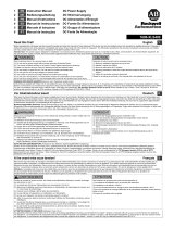
Wiring Scheme
24V Power
Supply
+
-
UB40.241
Input
+
-
+
-
24V Battery
Module
+
Buffered
Load
+
-
Non-
buffered
Load
+
-
Temp.
Sensor
Output
Battery
-
Bat1
12V
Bat2
12V
Center Tap
Temp. Sensor
DC-UPS
AC
DC
Output
Input
N L PE
+
+
optional
UZK24
+
-
Note1
Note2
Do not use wires smaller than 6mm
2
(AWG 10) and not longer than 2x1m
between the power supply and the DC-UPS controller.
Do not use wires smaller than 6mm
2
(AWG 10) and not longer than
2x1.5m between the battery and the DC-UPS controller.
Note1
Note2

EN
UB40.241 Installation Manual
Functional Description
The output can supply any kind of loads, including inductive loads and capacitive loads. If capacitors
with a capacitance >40mF are connected to the output, the unit might switch off in order to protect
itself.
Do not apply return voltages from the load to the output terminals higher than 35V.
Green Status LEDs
This LEDs are on solid, when the battery is charged more than 85%. During battery charging, the
LEDs are flashing with a slow frequency. Rapid flashing is an indication of a buffer event. After the unit
is turned on with charged batteries, it can take 20s or longer that the signal switches from charging to
ready. The LEDs are off when replace battery signal is active or the temperature of the DC-UPS or
battery is too hot. LED1 refers to battery 1, which is electrically closer to the (+) pole and LED 2 refers
to battery 2, which is closer to the (-) pole.
Yellow Diagnoses LED
This LED reports an overload situation: input currents above 40A, an expired buffer time (flashes for 15
minutes), an activated inhibit input or when the battery should be replaced.
Red Check Wiring LED
This LED indicates a failure in the installation such as too low or too high input voltage, too low battery
voltage, too high or too low battery temperature, too high DC-UPS controller temperature, incorrect wiring,
blown or missing battery fuse.
Buffer-time Limiter
The buffer time during a buffer event can be set to 10s, 30s, 1min, 3min, 10min or infinity with the dial
on the front. This can save battery energy for faster recharge and expand the lifetime of the battery.
When the dial is set to infinity, buffering continues until stopped by the battery deep-discharge
protection.
Battery Size Selector
Set the dial on the front of the unit according to the used battery size, which allows an optimal use of
the individual battery sizes. Set the unit to 12Ah for battery sizes between 12-17Ah, to 26Ah for 18-
34Ah batteries, to 38Ah for 35-50Ah batteries, to 65Ah for 51-80Ah batteries, to 100Ah for 81-130Ah
batteries and to 150Ah for 131-200Ah batteries.
Inhibit Input
The inhibit input disables or stops buffering. In power supply mode, a continuous input of 10-30V is
required. During buffering, a short input of 10-30V for at least 250ms is required to stop buffering. The
current of the inhibit input is limited to 6mA by the DC-UPS control unit.
Ready, Buffering and Replace Battery Relay Contacts
The Ready contact is closed when the battery is 85% charged and the unit is ready to buffer.
The Buffering contact is closed when the unit is in buffer mode.
The Replace Battery contact is closed when a battery replacement is necessary. The battery need to
be replaced is indicated by the green LED which is off (input voltage required).
Contact ratings: 30Vdc 1A, 30Vac 0.5A for resistive loads.
Battery-low Warning Contact
The battery-low pre-warning contact closes shortly before the battery is discharged. Contact ratings:
30Vdc 1A, 30Vac 0.5A for resistive loads.
LED Signal Pattern
Green Status LED:
Yellow Diagnosis LED:
Red Error LED:
1
0Check
Wiring
1
0Input
Voltage
1
0Temperature
1
0Ready
1
0Charging
1
0Buffering
5
Hz
1
0Replace Battery,
Temperature
1
0Overload
1
0Replace
Battery
1
0Buffertime
expired
1
0Inhibit
active
5
Hz
/