La página se está cargando...

DEUTSCH
PHOENIX CONTACT GmbH & Co. KG
D-32823 Blomberg, Germany
Fax +49-(0)5235-341200, Phone. +49-(0)5235-300
MNR 9039450-01 / 10.2008
www.phoenixcontact.com
DEUTSCH
ENGLISHFRANÇAISESPAÑOL
ENGLISHFRANÇAISESPAÑOL
© PHOENIX CONTACT 2008
TRIO-PS/1AC/48DC/5 Art.-Nr.: 2866491
Einbauanweisung für den Elektroinstallateur
Installation notes for electrical personnel
Instructions d’installation pour l’électricien
Instrucciónes de montaje para el instalador eléctrico
DE
EN
FR
ES
L
N
InputAC
100-240V
Output D
C
48
V
5
A
–
+
–
+
–
A
d
j
u
s
t
3
0
-5
6
V
D
C
O
K
TRIO POWER
T
R
IO
-
P
S
-
1
A
C
/
4
8
D
C
/
5
O
r
d
e
r
-
N
o
.:
2
8
6
6
4
9
1
I
n
p
u
t
:
1
0
0
-2
4
0
V
~
/
X
X
-X
X
A/
5
0
-
6
0
H
z
R
a
n
g
e
:
8
5
-2
6
4
V
~
O
u
tp
u
t
:
4
8
V
/
5
A
INDUSTRIAL
CONTROL
EQUIPME
NT
43K
A
E
N 61000-6-2
EN 61000-6-3
www.interface.phoenixcontact.com
A
P
P
R
O
V
A
L
S
R
e
a
d
in
s
t
a
l
l
a
t
io
n
i
n
s
tr
u
c
t
i
o
n
s
b
e
f
o
r
e
c
o
n
n
e
c
t
i
n
g
t
o
m
a
in
s
0
.
.
.
+
7
0
°
C
(
>
+
5
5
°
C
/
+
1
3
1
°
F
D
e
ra
ti
n
g
)
3
2
.
..
+
1
5
8
°
F
-
2
5
U
L
I
S
T
E
D
Sicherheits- und Warnhinweise
Um einen sicheren Betrieb des Gerätes zu gewährleisten und alle Funktionen nutzen zu
können, lesen Sie diese Anleitung bitte vollständig durch! Weitere Informationen finden Sie im
zugehörigen Datenblatt unter www.interface.phoenixcontact.com.
Die Installation und Inbetriebnahme darf nur von entsprechend qualifiziertem Fachpersonal durch-
geführt werden. Dabei sind die jeweiligen landesspezifischen Vorschriften (z.B. VDE, DIN) einzuhalten.
Insbesondere ist vor der Inbetriebnahme sicherzustellen, dass
• der Netzanschluss fachgerecht ausgeführt und der Schutz gegen elektrischen Schlag sicherge-
stellt ist!
• das Gerät nach den Bestimmungen der EN 60950 außerhalb der Stromversorgung spannungslos
schaltbar ist (z.B. durch den primärseitigen Leitungsschutz)!
• der Schutzleiter angeschlossen ist!
• alle Zuleitungen ausreichend abgesichert und dimensioniert sind!
• alle Ausgangsleitungen dem max. Ausgangstrom des Gerätes entsprechend dimensioniert oder
gesondert abgesichert sind!
• ausreichend Konvektion gewährleistet ist!
Die Stromversorgung ist ein Einbaugerät. Nach der Installation muss der Klemmenbereich abgedeckt
sein, um ausreichenden Schutz gegen unzulässiges Berühren spannungsführender Teile
sicherzustellen! Dieses ist durch einen Einbau im Schaltschrank bzw. Verteilerkasten gegeben.
Caractéristiques techniques
Référence
Entrée 1
Tension nominale d’entrée (plage étendue)
Plage de tensions d’entrée
Fréquence
Courant absorbé (pour valeurs nominales) env.
Limitation courant démarrage / I
2
t (+25 °C) typ.
Protection contre microcoupures pour charge nom. (typ.)
Durée démarrage après connexion de la tension réseau
Protection contre les transitoires varistance
Fusible amont recommendé disjoncteur de protection circuit
caractéristique
Courant de décharge vers PE
Sortie 2
Tension nominale U
N
/ tolérance
Plage de réglage de la tension de sortie
Courant nom. de sortie I
N
(refroidis. par convection): -25 °C à +55 °C
Derating à partir de +55 °C
Limitation intensité en cas court-circuit env.
Démarrage charges capacitives illimité
Dissip. puissance max. vide/charge nom. env.
Rendement (pour 230V AC et valeurs nominales)
Ondul. résid./ pointes commut. (20 MHz) (pour valeurs nominales)
Montage en parallèle pour redondance et augmentation puissance
Protection contre surtensions internes
Protection contre courants d'amont
Signalisation
LED 6 (U
out
> 0,9 x U
N
= LED allumée)
Certification / normes
Equipement électrique des machines (Catégorie de surtension III)
Transformateurs de sécurité pour éléments réseaux de distribution
Sécurité électrique des matériels de traitements de l'information
Dispositif de réglage industriel
Matériel électrique pour les zones exposées aux risques
d'explosion
Equipement électronique des installations à courant fort
Faible tension de protection
Isolement sécurisé
Protection contre le choc électrique
Protection contre les courants dangereux, Exigences fondamen-
tales pour un isolement sûr dans les équipements électr.
Limites pour les émissions de courants harmoniques d’après
Autres caractéristiques
Tension d’isolement :
Entrée / sortie essai de type/essai indiv.
Entrée / PE essai de type/essai indiv.
Sortie / PE essai indiv.
Degrée de protection
Classe de protection (avec connexion PE)
MTBF selon CEI 61709 (SN 29500)
Bôitier isolant
Aluminium (AlMg3) + tôlé d'acier galvanisée, fermé
Dimensions (l / H / P) + profilé
Poids env.
Caractéristiques climatiques
Température ambiante service
stockage
Humidité à +25 °C, sans condensation
Vibration selon CEI 60068-2-6
Choc (dans toutes les directions spatiales)selon CEI 60068-2-27
Degrée de pollution selon EN 50178
Classe d'atmosphère selon EN 60721
Conforme à la directive 2004/108/CE
et à la directive basse tension 2006/95/EE
CEM (Compatibilité électromagnétique)
Immunité selon EN 61000-6-2
• EN 61000-4-2
2)
Décharge électrostatique (ESD)
Boîtier
par contact:
dans l'air:
• EN 61000-4-3
1)
champ électromagnétique HF
Boîtier
Fréquence/intensité champ:
• EN 61000-4-4
2)
Transitoires électriques rapides
(en salves):
Entrée:
Sortie:
Signal:
• EN 61000-4-5
2)
Ondes de choc (Surge):
Entrée:
Sortie:
Signal:
• EN 61000-4-6
1)
Perturbations conduites
E/S:
Fréquence / U
o
:
• EN 61000-4-11
2)
Creux de tension
Entrée: voir protection
contre micro-coupures
Emission selon EN 61000-6-3
• Perturbations radioélectriques
• Tension perturbatrices radioélectriques
EN 55011 correspond à CISPR11 / EN 55022 correspond à
CISPR22 / EN 61000 correspond à CEI 61000
1)
Critère A:
Fonctionnement normal à l'intérieur des limites
fixées.
2)
Critère B:
Perturbation provisoire du fonctionnement,
que le module corrige de lui-même.
3)
symétrique:
ligne contre ligne.
4)
asymétrique:
ligne contre terre.
5)
Classe B:
Secteur d'application Industrie et zone résidenti-
elle.
c
Datos técnicos
Código
Entrada 1
Tensión nominal de entrada (amplio rango de entrada)
Margen de tensión de entrada
Frecuencia
Absorción de corriente (p. valores nominales) aprox.
Limitación de la corriente de cierre / I
2
t (+25 °C) típ.
Puenteo en fallo de red para carga nominal (típ.)
Tiempo de conexión al aplicar la tensión de red
Protección contra sobretensiones transitorias varistor
Fusible previo recomendado interruptores automáticos
característica
Corriente de derivación a tierra (PE)
Salida 2
Tensión nominal de salida U
N
/ tolerancia
Margen ajustable de la tensión de salida
Corriente nominal de salida I
N
p. refrigeración
por convección: -25 °C hasta +55 °C
Derating a partir de +55 °C
Limitación de corriente en cortocircuito aprox.
Arranque de cargas capacitivas ilimitadas
Disipación máx.: en circuito abierto/a carga nom aprox.
Rendimiento (para 230V AC y valores nominales)
Ondulación residual/picos de conexión (20 MHz)(para valores nomin.)
Conectable en paralelo para redundancia y aumento de potencia
Protección contra sobretensiones internas
Resistencia a la alimentación de retorno
Señalización
LED 6 (U
out
> 0,9 x U
N
= LED encendido)
Certificación/normas
Equipamiento eléctrico de máquinas (categoría de sobretensiones III)
Transformadores de seguridad para fuentes de conmutación
Seguridad eléctrica (de dispositivos de la técnica de información)
Regulación industrial
Aparatos eléctricos para recintos expuestos al peligro de explosión
Equipamiento de instalaciones de alta intensidad con aparatos
electrónicos
Tensión baja de protección
Separación segura
Protección contra descarga eléctrica
Protección contra corrientes corpóreas peligrosas, exigencias bási-
cas para la separación segura de aparatos eléctricos
Limitación de corrientes armónicas de la red según
Datos generales
Tensión de aislamiento:
Entrada / salida prueba típo/ensayo individual
Entrada / PE prueba típo/ensayo individual
Salida / PE ensayo individual
Protección
Clase de protección (con conexión a tierra (PE))
MTBF según IEC 61709 (SN 29500)
Aislamiento
Aluminio (AlMg3) + chapa de acero galvanizada, cerrado
Dimensiones (A / A / P) + carril
Peso aprox.
Datos climáticos
Temperatura ambiente servicio
almacenamiento
Humedad para +25 °C, sin condensación
Vibración según IEC 60068-2-6
Choque (en todas las direcciones espaciales) según IEC 60068-2-27
Grado de suciedad según EN 50178
Clima según EN 60721
Conformidad con la directriz CEM 2004/108/CE
y con la directriz de baja tensión 2006/95/CE
Compatibilidad electromagnética (CEM)
Resistencia a interferencias según EN 61000-6-2
• EN 61000-4-2
2)
Descarga de electricidad estática
(ESD)
caja
descarga en contactos:
descarga en el aire:
• EN 61000-4-3
1)
Campo electromagnético de AF
caja
frecuencia/intens. de campo:
• EN 61000-4-4
2)
Transitorios rápidos (Burst):
entrada:
salida:
señal:
• EN 61000-4-5
2)
Cargas de sobrecorriente (Surge):
entrada:
salida:
señal:
• EN 61000-4-6
1)
Perturbaciones en la línea
E/S:
frecuencia / U
o
:
• EN 61000-4-11
2)
Fallos de tensión
entrada: ver puenteado en
fallo de la red
Radiación de perturbaciones según EN 61000-6-3
• Radiointerferencias
• Tensión radiointerferencia
EN 55011 equivale a la CISPR11 / EN 55022 equivale a la CISPR22
/ EN 61000 equivale a la IEC 61000
1)
Criterio A:
Comportamiento de servicio normal dentro de
los límites determinados.
2)
Criterio B:
Alteración transitoria del comportamiento de ser-
vicio que corrige el propio aparato.
3)
simétrica:
Conductor contra conductor.
4)
asimétrica:
Conductor contra tierra.
5)
clase B:
Campo de empleo industrial y de viviendas.
c
Technische Daten
Artikel Nr.
Eingangsdaten 1
Nenneingangsspannung (Weitbereichseingang)
Eingangsspannungsbereich
Frequenz
Stromaufnahme (bei Nennwerten) ca.
Einschaltstrombegrenzung / I
2
t (+25 °C) typ.
Netzausfallüberbrückung bei Nennlast (typ.)
Einschaltzeit nach Anlegen der Netzspannung
Transientenüberspannungsschutz Varistor
Empfohlene Vorsicherung Leitungsschutzschalter
Charakteristik
Ableitstrom gegen PE
Ausgangsdaten 2
Nennausgangsspannung U
N
/ Toleranz
Einstellbereich der Ausgangsspannung
Nennausgangsstrom I
N
bei Konvektionskühlung:-25 °C bis +55 °C
Derating ab +55 °C
Strombegrenzung bei Kurzschluss ca.
Anlauf unbegrenzter kapazitiver Lasten
max. Verlustleistung Leerlauf/Nennlast ca.
Wirkungsgrad (bei 230 V AC und Nennwerten)
Restwelligkeit / Schaltspitzen (20 MHz) (bei Nennwerten)
Parallelschaltbar zur Redundanz und Leistungserhöhung
Überspannungsschutz gegen interne Überspannungen
Rückeinspeisungsfestigkeit
Signalisierung
LED 6 (U
out
> 0,9 x U
N
= LED leuchtet)
Zertifizierung/Normen
Elektrische Ausrüstung von Maschinen (Überspannungskategorie III)
Sicherheitstransformatoren für Schaltnetzteile
Elektrische Sicherheit (von Einrichtungen der Informationstechnik)
Industrielle Regeleinrichtung
Elektrische Betriebsmittel für explosionsgefährdete Räume
Ausrüstung von Starkstromanlagen mit elektronischen Betriebs-
mitteln
Schutzkleinspannung
Sichere Trennung
Schutz gegen elektrischen Schlag
Schutz gegen gefährliche Körperströme, Grundanforderungen für si-
chere Trennung in elektrischen Betriebsmitteln
Begrenzung Netz-Oberschwingungsströme gemäß
Allgemeine Daten
Isolationsspannung:
Ein-/Ausgang Typprüfung/Stückprüfung
Eingang / PE Typprüfung/Stückprüfung
Ausgang / PE Stückprüfung
Schutzart
Schutzklasse (mit PE-Anschluss)
MTBF nach IEC 61709 (SN 29500)
Ausführung des Gehäuses
Aluminium (AlMg3) + Stahlblech verzinkt, geschlossen
Abmessungen (B / H / T) + Tragschiene
Gewicht ca.
Klimatische Daten
Umgebungstemperatur Betrieb
Lagerung
Feuchtigkeit bei +25 °C, keine Betauung
Vibration nach IEC 60068-2-6
Schock (in alle Raumrichtungen) nach IEC 60068-2-27
Verschmutzungsgrad nach EN 50178
Klimaklasse nach EN 60721
Konform zur EMV-Richtlinie 2004/108/EG
und zur Niederspannungsrichtlinie 2006/95/EG
EMV (Elektromagnetische Verträglichkeit)
Störfestigkeit nach EN 61000-6-2
• EN 61000-4-2
2)
Entladung statischer Elektrizität
(ESD)
Gehäuse
Kontaktentladung:
Luftentladung:
• EN 61000-4-3
1)
elektromagnetisches HF-Feld
Gehäuse
Frequenz / Feldstärke:
• EN 61000-4-4
2)
schnelle Transienten (Burst):
Eingang:
Ausgang:
• EN 61000-4-5
2)
Stoßstrombelastungen (Surge):
Eingang:
Ausgang:
• EN 61000-4-6
1)
leitungsgeführte Beeinflussung
E/A:
Frequenz / U
o
:
• EN 61000-4-11
2)
Spannungseinbrüche
Eingang: siehe Netzausfall-
überbrückung
Störabstrahlung nach EN 61000-6-3
• Funkstörstrahlung
• Funkstörspannung
EN 55011 entspricht der CISPR11 / EN 55022 entspricht der
CISPR22 / EN 61000 entspricht der IEC 61000
1)
Kriterium A:
Normales Betriebsverhalten innerhalb der fest-
gelegten Grenzen.
2)
Kriterium B:
Vorübergehende Beeinträchtigung des Betriebs-
verhaltens, die das Gerät selbst wieder korrigiert.
3)
symmetrisch:
Leitung gegen Leitung.
4)
unsymmetrisch:
Leitung gegen Erde.
5)
Klasse B:
Einsatzgebiet Industrie und Wohnbereich.
c
TRIO-PS/1AC/48DC/5
2866491
100 - 240 V AC
85 - 264 V AC
45 - 65 Hz
2,8 A (100 V AC) / 1,2A (240 V AC)
< 15 A / < 0,7 A
2
s
> 15 ms (120 V AC) / > 16 ms (230 V AC)
< 1 s
10 A / 16 A
B
< 3,5 mA
48 V DC / ± 1 %
30 - 56 V DC
5 A (U
out
= 48 V DC)
2,5 %/K
5,7 A
3,5 W / 28 W
89 %
< 50 mV
PP
, < 60 V DC
60 V DC
LED grün / green / verte / verde
EN 60204
EN 61558-2-17
EN 60950 / VDE 0805,
UL/C-UL Recognized UL 60950 u
UL/C-UL Listed UL 508
UL/C-UL Recognized UL 1604
Class I, Division 2, Groups A, B, C, D
EN 50178/VDE 0160
PELV (EN 60204) / SELV (EN 60950)
VDE 0100-410
DIN 57100-410
DIN VDE 0106-101
EN 61000-3-2
4 kV AC / 2 kV AC
2 kV AC / 2 kV AC
500 V DC
IP20
Ι
> 500 000 h
(60 / 130 / 152,5) mm
1,1 kg
-25 °C … +70 °C (> +55 °C Derating: 2,5 %/K)
-40 °C … +85 °C
≤ 95 %
< 15 Hz, Amplitude ± 2,5 mm
15 Hz-150 Hz, 2,3 g, t
V
= 90 min.
30 g
2
3K3
TRIO-PS/1AC/48DC/5
Level 3
6 kV
8 kV
Level 3
80 MHz-3,0 GHz / 10 V/m
4 kV (Level 4)
4)
2 kV (Level 3)
4)
4 kV
4)
/ 2 kV
3)
(Level 4)
2 kV
4)
/ 1 kV
3)
(Level 2)
Level 3
10 kHz-80 MHz / 10 V
>10 ms
EN 55011 (EN 55022) Klasse B
5)
EN 55011 (EN 55022) Klasse B
5)
LISTED
U
Technical Data
Order No.
Input Data 1
Nominal input voltage (wide-range input)
Input voltage range
Frequency
Current consumption (at nominal values) approx.
Inrush current limitation/ I
2
t (+25 °C) typ.
Mains buttering at nominal load (typ.)
Turn-on time after applying the mains voltage
Transient surge voltage protection varistor
Recommended backup fuse power circuit-breaker
characteristic
Discharge current to PE
Output Data 2
Nominal output voltage U
N
/ tolerance
Setting range of the output voltage
Nominal output current I
N
with convection cooling:-25 °C to +55 °C
Derating from +55 °C
Current limitation at short-circuits approx.
Startup of unlimited capacitive loads
Max. power dissipation idling/nominal load approx.
Efficiency (at 230V AC and nominal values)
Residual ripple/ peak switching (20 MHz) (at nominal values)
Can be connected in parallel for redundancy and increased capacity
Surge voltage protection against internal surge voltages
Resistance to reverse feed
Signaling
LED 6 (U
out
> 0.9 x U
N
= LED ON)
Ratings/Standards
Electrical equipment of machines (surge voltage category III)
Safety transformers for switched-mode power supply units
Electrical safety (of information technology equipment)
Industrial regulating devices
Electrical equipment for potentially explosive areas
Electronic equipment for use in electric power inst.
Protective low voltage
Safe isolation
Protection against electric shock
Protection against shock currents, basic requirements for protec-
tive separation in electrical equipment
Limitation of mains harmonic currents acc. to
General Data
Isolation voltage:
input / output type test/routine test
input / PE type test/routine test
output / PE routine test
Degree of protection
Class of protection (with PE connection)
MTBF in acc. with IEC 61709 (SN 29500)
Type of housing
Aluminum (AlMg3) + zinc-plated sheet steel, enclosed
Dimensions (W / H / D) + mounting rail
Weight approx.
Climatic Data
Ambient temperature operation
storage
Humidity at +25 °C, no condensation
Vibration in acc. with IEC 60068-2-6
Shock (in all directions) in acc. with IEC 60068-2-27
Contamination class in acc. with EN 50178
Climatic class in acc. with EN 60721
in conformance with EMC guideline 2004/108/EC
and low voltage directive 2006/95/EC
EMC (electromagnetic compatibility)
Immunity to interference according to EN 61000-6-2
• EN 61000-4-2
2)
Discharge of static electricity (ESD)
Housing
Contact discharge:
Discharge in air:
• EN 61000-4-3
1)
Electromagnetic HF field
Housing
Frequency/Field intensity:
• EN 61000-4-4
2)
Fast transients (Burst):
Input:
Output:
Signal:
• EN 61000-4-5
2)
Surge voltage capacities (Surge):
Input:
Output:
Signal:
• EN 61000-4-6
1)
Conducted disturbance
I/O:
Frequency / U
o
:
• EN 61000-4-11
2)
Voltage dips
Input: see mains buffering
Noise emission according to EN 61000-6-3
• Emitted radio interference
• Radio interference voltage
EN 55011 corresponds to CISPR11 / EN 55022 corresponds to
CISPR22 / EN 61000 corresponds to IEC 61000
1)
Criterion A:
Normal operating behavior within the defined lim-
its.
2)
Criterion B:
Temporary impairment to operational behavior
that is corrected by the device itself.
3)
Symmetrical:
Conductor to conductor.
4)
Asymmetrical:
Conductor to ground.
5)
Class B:
Area of application industry and residential.
c
Safety and warning notes
In order to guarantee safe operation of the device and to be able to make use of all the
functions, please read these instructions thoroughly! Further technical information can be
found in the associated data sheet under www.interface.phoenixcontact.com.
The device may only be installed and put into operation by qualified personnel. The corresponding
national regulations (e.g. VDE, DIN) must be observed.
Before putting the device into operation, ensure that
• the mains connection has been carried out by a competent person and protection against electric
shock is guaranteed!
• the device can be disconnected outside the power supply unit in accordance with the regulations
as in EN 60950 (e.g. through primary side line protection)!
• the ground conductor is connected!
• all feed lines are sufficiently protected and dimensioned!
• all output lines are dimensioned according to the maximum output current of the device or
separately protected!
• sufficient convection is guaranteed!
The power supply is a device for installation as built-in equipment. After installation, the termination
area must be covered to ensure sufficient protection against accidental contact with live parts. This
requirement is met by installing the device in the control cabinet or in a distributor box.
Conseils de sécurité et avertissements
Pour garantir un fonctionnement fiable du module et pouvoir utiliser toutes ses fonctions,
veuillez lire la présente notice dans son intégralité ! Pour de plus amples informations techniques
voir www.interface.phoenixcontact.com.
Leur installation et leur mise en service ne doivent être confiées qu'à un personnel spécialisé
dûment qualifié. Il faut par ailleurs respecter les normes nationales spécifiques applicables (par
exemple NF, etc.).
Il faut en particulier, avant la mise en service, s'assurer que
• la connexion au réseau est réalisée selon les règles et que la protection contre les chocs électriques
est assurée !
• l'appareil peut être mis hors tension selon les dispositions de la norme EN 60950 en dehors de l'ali-
mentation (par ex. via le disjoncteur du circuit côté primaire) !
• le conducteur de protection est raccordé !
• toutes les lignes d'arrivée sont suffisamment dimensionnées et protégées !
• toutes les lignes de sortie sont dimensionnées pour l'intensité max. de sortie de l'appareil ou
protégées par un fusible spécial !
• la convection est suffisante !
Les alimentations doivent être encastrés. Une fois l’installation réalisée, la zone des blocs de jonction
doit être recouverte de manière à assurer une protection suffisante contre les contacts accidentels avec
des parties sous tension. Pour cela, on les encastrera dans une armoire ou un coffret de raccordement.
Indicaciones de seguridad y advertencias
Para garantizar un funcionamiento seguro del módulo y poder utilizar todas las funciones,
rogamos lea estas instrucciones atentamente. Más informaciones técnicas las encontrará Vd. en
la hoja de características (www.interface.phoenixcontact.com).
La instalación y la puesta en marcha solo puede ser efectuada por personal correspondientemente
especializado. A tal efecto, deben considerarse las normas respectivas del país (p.ej. VDE, DIN).
En particular, antes de la puesta en marcha hay que asegurarse de que,
• la conexión a la red se ha instalado profesionalmente y que está garantizada la protección contra
descarga eléctrica,
• el módulo puede desconectarse de la tensión desde el exterior de la fuente de alimentación según
las especificaciones de la EN 60950 (p.ej. mediante la protección de la línea del primario),
• el conductor de protección a tierra está conectado!
• todos los cables de alimentación están suficientemente protegidos y dimensionados,
• todos los cables de salida están dimensionados para la corriente de salida máxima del módulo, o
protegidos por fusible por separado,
• está garantizada una convección suficiente.
El fuente de alimentación es un módulo para instalación incorporada. Después de la instalación se tie-
ne que cubrir la zona de bornes, para garantizar una protección suficiente contra roces involuntarios
con piezas en tensión. Este requisito se cumple mediante un montaje en armario o caja de distribución.

DEUTSCH
ENGLISH FRANÇAIS ESPAÑOL
Alimentation à découpage primaire
TRIO-PS/1AC/48DC/5
Référence: 2866491
1. Éléments de connexion et éléments de commande
(Fig. 1):
2. Installation (Fig. 3)
Cette alimentation s'encliquette sur les profilés 35 mm selon EN 60715. Elle doit
être montée horizontalement (bornes d'entrée en bas).
3. Raccordement / Câble de liaison:
Utiliser des câbles en cuivre capables de résister à des températures de service
de > 75 °C pour respecter l'homologation UL.
Pour respecter les consignes d'EN 60950/UL 60950, il faut que les câbles souples
aient des embouts. Pour le raccordement sûr d’appareils, les embouts doivent
avoir une longueur minimale de 10 mm.
Utiliser un tournevis dont la largeur de la lame est adéquate pour le câblage. Vous
pouvez raccorder des câbles avec les sections suivantes :
Isoler les extrémités selon le tableau 1 (fig. 2) pour obtenir un raccordement fiable
et protégé contre les contacts fortuits !
4. Entrée (1, Fig. 1, Fig. 5)
Pour le raccordement 100-240 V AC, on utilise les connexions à vis L, N et .
L'appareil peut être connecté à des réseaux de courant alternatif monophasés ou
à deux phases de réseaux triphasés (réseau TN, TT ou IT selon VDE 0100 T 300/
CEI 364-3) avec des tensions nominales de 100-240 V AC.
Fusibles amonts recommandés : disjoncteurs de protection 10 A ou 16 A, carac-
téristique B (ou équivalents).
Pour respecter l'homologation UL ne raccorder qu'un seul module à un fusible
monté en amont.
5. Sortie (2, Fig. 1)
Le raccordement 48 V DC se fait via les connexions vissées "+" et "–". A la livrai-
son, la tension de sortie est réglée sur 48 V DC. Le potentiomètre
3 permet de la
régler de 30 à 56 V DC.
Le module est doté d'une protection électronique contre les courts-circuits et la
marche à vide. En cas de défaut, la tension de sortie est limitée à 60 V DC max.
5.1. Signalisation (4, Fig. 1)
La LED DC OK est disponible pour surveiller le fonctionnement. La LED reste al-
lumée en permanence quand la tension de sortie est supérieure à 30 V.
5.2. Courbe de sortie (Fig. 6)
Le module fonctionne selon la courbe caractéristique U/I. Le courant de sortie est
limité à I
BOOST
en cas de court-circuit ou de surcharge. La tension secondaire res-
te diminuée tant que le court-circuit du côté secondaire n'est pas éliminé.
5.3. Comportement en fonction de la température (Fig.7)
Au-delà de +55 °C, la puissance de sortie doit être réduite de 2,5 % pour chaque
élévation d'un Kelvin de la température.
Si les températures ambiantes dépassent +70 °C ou en cas de surcharge ther-
mique, le module ne se déactive pas. La puissance de sortie est réduite jusqu'à
l'obtention d'une protection du module.
Tableau 1:
Rigide Souple Couple de serrage Longueur à dénuder
[mm
2
][mm
2
] AWG [Nm] [lb in] L [mm]
1 0,2-2,5 0,2-2,5 24-14 0,4 - 0,5 3,5 - 4,5 9
2 0,2-2,5 0,2-2,5 24-14 0,4 - 0,5 3,5 - 4,5 9
1 Entrée AC: Tensión d’entrée
100-240 V AC, fréquence 45-65 Hz
2 Sortie DC: Tensión de sortie
48 V DC (préréglée),
réglable de 30 - 56 V DC via
potentiomètre 3
3
Potentiomètre 30 - 56 V DC
4 Témoin DC OK, verte
5 Adaptateur pour profilé universel
UTA 107
6 Support pour serre-câbles
Attention : Ne jamais travailler sur un module sous tension !
Danger de mort !
ATTENTION - Risque d’explosion - Débrancher uniquement
l’equipement si l’alimentation a été coupée ou si la
zone est désignée comme une zone non dangereuse.
Le remplacement des composants peut remettre en
cause l’utilisation en atmosphères explosibles (class
I, division 2).
Nous recommandons de respecter une distance min. de 5 cm
au-dessus / en dessous du module par rapports aux autres
modules pour obtenir un refroidissement par convection
suffisant. Un espace sur le côté par rapport à d'autres modules
n'est pas nécessaire pour l'utilisation conforme de l'appareil.
Selon la température ambiante et la sollicitation du module, la
température du bôitier peut atteindre des valeurs élevées !
5
Primary Switched-Mode Power Supply Unit
TRIO-PS/1AC/48DC/5
Order No.: 2866491
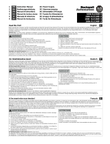
1. Equipment connections and operating elements
(Fig. 1):
2. Installation (Fig. 3)
The power supply unit can be snapped onto 35 mm mounting rails in acc. with EN
60715. Installation should be made horizontally (input terminal blocks below).
3. Connection / Connecting Cable:
In order to comply with the UL certification, use copper cables that are designed
for operating temperatures of > 75 °C.
In order to comply with EN 60950/UL 60950, flexible cables require ferrules. To
safely connect a device, the ferrules should have a length of at least 10 mm.
Please use a screwdriver with a suitable blade width for wiring. You can connect
the following cable cross sections:
To achieve a reliable and shockproof connection, strip the connecting ends
according to table 1 (Fig.2)!
4. Input (1, Fig. 1, Fig. 5)
The 100-240 V AC connection is made using the L, N and screw connections.
The device can be connected to single-phase AC networks or to two of the phase
conductors of three-phase networks (TN, TT or IT networks in acc. with VDE 0100
Part 300/IEC 364-3) with nominal voltages of 100-240 V AC.
Recommended backup fuses are power circuit-breakers 10 A or 16 A, characteri-
stic B (or identical function).
In order to comply with the UL rating, no more than one device may be connected
to an upstream fuse.
5. Output (2, Fig. 1)
The 48 V DC connection is made using the "+" and "–" screw connections. At the
time of delivery, the output voltage is 48 V DC. The output voltage can be set from
30 to 56 V DC on the potentiometer
3.
The device is electronically protected against short-circuit and idling. In the event
of a malfunction, the output voltage is limited to 60 V DC.
5.1. Signaling (4, Fig. 1)
For function monitoring, there is the DC OK LED.
The LED lights up permanently when the output voltage is more than 30 V.
5.2. Output characteristic curve (Fig. 6)
The device functions following the U-I characteristic curve. Under load, the
operating point follows this curve. In the event of a short circuit or overload, the out-
put current is limited. The secondary voltage is reduced until the short circuit on
the secondary side has been remedied.
5.3. Thermal behaviour (Fig.7)
In the case of ambient temperatures above +55°C, the output capacity has to be
reduced by 2.5% per Kelvin increase in temperature.
The device does not switch off in the case of ambient temperatures above +70°C
or thermal overload. The output capacity is reduced as far as necessary to provide
device protection.
Table 1:
Solid Stranded Torque Stripping length
[mm
2
][mm
2
] AWG [Nm] [lb in] L [mm]
1 0.2-2.5 0.2-2.5 24-14 0.4 - 0.5 3.5 - 4.5 9
2 0.2-2.5 0.2-2.5 24-14 0.4 - 0.5 3.5 - 4.5 9
1 AC input: Input voltage
100-240 V AC, frequency 45-65 Hz
2 DC output: Output voltage
48 V DC (preset), can be
adjusted from 30 to 56 V DC
via potentiometer 3
3
Potentiometer 30 - 56 V DC
4 DC OK control lamp, green
5 Universal mounting rail adapter
UTA 107
6 Connection for cable ties
Caution: Never carry out work on live parts!
Danger of fatal injury!
WARNING - Explosion Hazard - Do not disconnect equipment
unless power has been switched off or the area is
known to be non-hazardous.
WARNING - Explosion Hazard - substitution of components
may impair suitability for Class I, Division 2.
In order to guarantee sufficient convection, we recommend
observing a minimum distance to other modules of 5 cm
above and below the device.
In order for the device to function in the manner intended, it is
not necessary to observe any lateral spacing to other modules.
Depending on the ambient temperature and load of the device,
the temperature of the housing can become very high!
5
Primär getaktete Stromversorgung
TRIO-PS/1AC/48DC/5
Artikelnr.: 2866491
1. Geräteanschlüsse, -bedienungselemente
(Abb. 1):
2. Installation (Abb. 3)
Die Stromversorgung ist auf 35 mm-Tragschienen nach EN 60715 aufrastbar. Die
Montage sollte waagerecht erfolgen (Eingangsklemmen unten).
3. Anschluss / Verbindungskabel:
Zur Einhaltung der UL Approbation verwenden Sie Kupferkabel, die für Betriebs-
temperaturen > 75 °C ausgelegt sind.
Zur Einhaltung der EN 60950/UL 60950 benötigen flexible Kabel Aderendhülsen.
Für den sicheren Geräteanschluss sollten die Aderendhülsen eine Mindestlänge
von 10 mm aufweisen.
Verwenden Sie zum Verdrahten einen Schraubendreher mit geeigneter Klingenbrei-
te. Sie können folgende Kabelquerschnitte anschließen:
Für zuverlässigen und berührsicheren Anschluss isolieren Sie die Anschlussen-
den entsprechend Tabelle 1 ab (Abb.2)!
4. Eingang (1, Abb. 1, Abb. 5)
Der 100-240 V AC-Anschluss erfolgt über die Schraubverbindungen L, N und .
Das Gerät kann an einphasigen Wechselstromnetzen oder an zwei Außenleitern
von Drehstromnetzen (TN-, TT- oder IT-Netz nach VDE 0100 T 300/IEC 364-3)
mit Nennspannungen 100-240 V AC angeschlossen werden.
Empfohlene Vorsicherungen sind Leitungsschutzschalter 10 A oder 16 A,
Charakteristik B (oder funktionsgleich).
Zur Einhaltung der UL Approbation darf nicht mehr als ein Gerät an eine vorge-
schaltete Sicherung angeschlossen werden.
5. Ausgang (2, Abb. 1)
Der 48 V DC-Anschluss erfolgt über die Schraubverbindungen "+" und "–". Die
eingestellte Ausgangsspannung beträgt bei Auslieferung 48 V DC. Am Potentio-
meter
3 ist die Ausgangsspannung von 30 bis 56 V DC einstellbar.
Das Gerät ist elektronisch kurzschluss- und leerlauffest. Die Ausgangsspannung
wird im Fehlerfall auf maximal 60 V DC begrenzt.
5.1. Signalisierung (4, Abb. 1)
Zur Funktionsüberwachung steht die DC OK-LED zur Verfügung. Die LED leuch-
tet dauerhaft, wenn die Ausgangsspannung mehr als 30 V beträgt.
5.2. Ausgangskennlinie (Abb. 6)
Das Gerät arbeitet nach der U-I-Kennlinie. Diese wird bei Belastung vom Arbeits-
punkt durchlaufen. Der Ausgangsstrom wird bei Kurzschluss oder Überlast be-
grenzt. Die Sekundärspannung wird dabei so lange abgesenkt, bis der sekundär-
seitige Kurzschluss oder die Überlastung behoben ist.
5.3. Temperaturverhalten (Abb.7)
Bei Umgebungstemperaturen über +55 °C muss die Ausgangsleistung um 2,5 %
je Kelvin Temperaturerhöhung reduziert werden.
Bei Umgebungstemperaturen über +70 °C bzw. thermischer Überlastung schaltet
das Gerät nicht ab. Die Ausgangsleistung wird so weit reduziert, dass ein Geräte-
schutz gegeben ist.
Tabelle 1:
Starr Flexibel Anzugsmoment Abisolierlänge L
[mm
2
][mm
2
] AWG [Nm] [lb in] [mm]
1 0,2-2,5 0,2-2,5 24-14 0,4 - 0,5 3,5 - 4,5 9
2 0,2-2,5 0,2-2,5 24-14 0,4 - 0,5 3,5 - 4,5 9
1 AC-Eingang: Eingangsspannung
100-240 V AC, Frequenz 45-65 Hz
2 DC-Ausgang: Ausgangsspan-
nung 48 V DC (voreingestellt),
von 30 - 56 V DC einstellbar über
Potentiometer 3
3
Potentiometer 30 - 56 V DC
4 DC OK-Kontrollleuchte grün
5 Universal-Tragschienen-Adapter
UTA 107
6 Aufnahme für Kabelbinder
Vorsicht: Niemals bei anliegender Spannung arbeiten!
Lebensgefahr!
ACHTUNG - Explosionsgefahr - Betriebsmittel nur entfernen,
wenn es sich im spannungslosen Zustand oder im
nicht-explosionsgefährdeten Bereich befindet.
Das Ersetzen von Komponenten kann die Eignung
zum Einsatz in explosionsgefährdeten Bereichen in
Frage stellen (Class I, Division 2).
Für ausreichende Konvektion wird die Einhaltung eines Min-
destabstands zu anderen Modulen von 5 cm oberhalb
und unterhalb des Gerätes empfohlen.
Für die bestimmungsgemäße Gerätefunktion ist die Einhaltung ei-
nes seitlichen Abstands zu weiteren Modulen nicht erforderlich.
Je nach Umgebungstemperatur und Belastung des Gerätes
kann die Gehäusetemperatur hohe Werte annehmen!
5
Fuente de alimentación conmutada en primario
TRIO-PS/1AC/48DC/5
Código: 2866491
1. Conexiones y elementos de operación
(Fig. 1):
2. Instalación (Fig. 3)
La fuente de alimentación puede encajarse en los carriles 35 mm según EN 60715.
El montaje tiene que realizarse en posición horizontal (bornes de entrada abajo).
3. Conexión / Cables de conexión:
Para cumplir la aprobación UL utilice cables de cobre dimensionados para
temperaturas de servicio de > 75 °C.
Para cumplir la EN 60950/UL 60950, los cables flexibles deben equiparse con
punteras. Para una conexión segura del aparato, las punteras deben tener una
longitud mínima de 10 mm.
Para cablear, utilice un destornillador con ancho de boca apropiado. Se pueden
conectar las siguientes secciones de cable:
Para obtener una conexión fiable y protegida contra roces involuntarios desaisle
los finales de conductor según la tabla 1 (Fig.2)!
4. Entrada (1, Fig. 1, Fig. 5)
La conexión de 100-240 V AC se efectúa a través de las conexiones de tornillo L, N
y . El módulo se conecta a redes de corriente alterna monofásicas o a dos
fases de redes trifásicas (red TN, TT o IT según VDE 0100 T 300/IEC 364-3) con
tensiones nominales de 100-240 V AC.
Fusibles previos recomendados: interruptor automático de 10 A ó 16 A,
característica B (o de función similar).
Para cumplir la homologación UL, no debe conectarse más de un aparato a un fu-
sible preconectado.
5. Salida (2, Fig. 1)
La conexión de 48 V DC se efectúa mediante las conexiones de tornillo "+" y "–". La
tensión de salida está ajustada de fábrica a 48 V DC. Con el potenciómetro
3, la
tensión de salida puede ajustarse entre 30 y 56 V DC.
El módulo está protegido electrónicamente contra cortocircuito y en circuito abier-
to. En caso de fallo, la tensión de salida se limita como máximo a 60 V DC.
5.1. Señalización (4, Fig. 1)
Para el control funcional se dispone del LED DC OK.
El LED emite luz continuamente si la tensión de salida es superior a 30 V.
5.2. Característica de salida (Fig. 6)
El módulo trabaja según la característica U-I. En una carga, el punto de trabajo re-
corre esta curva característica. En caso de cortocircuito, la corriente de salida o la
sobrecarga se limita a I
BOOST
. En eso, la tensión del secundario permanece re-
ducida hasta que se haya eliminado el cortocircuito del secundario.
5.3. Comportamiento de temperatura (Fig.7)
Para temperaturas ambiente superiores a +55 °C, la potencia de salida tiene que
reducirse en 2,5 % por grado Kelvin de aumento de temperatura.
En caso de temperaturas ambiente superiores a +70 °C o en caso de sobrecargas
térmicas, el aparato no se desconecta. La potencia de salida es reducida de tal
manera que quede garantizada la protección del aparato.
Tabla 1:
Rígido Flexible Par de apriete Longitud a desaislar
[mm
2
][mm
2
] AWG [Nm] [lb in] L [mm]
1 0,2-2,5 0,2-2,5 24-14 0,4 - 0,5 3,5 - 4,5 9
2 0,2-2,5 0,2-2,5 24-14 0,4 - 0,5 3,5 - 4,5 9
1 Entrada AC: Tensión de entrada
100-240 V AC, frequencia 45-65 Hz
2 Salida DC: Tensión de salida
48 V DC (ajuste previo),
de 30 - 56 V DC ajustable
mediante potenciómetro 3
3
Potenciómetro 30 - 56 V DC
4 Piloto de control verde OK DC
5 Adaptador universal para carril
UTA 107
6 Recepción para sujeta-cables
Atención: ¡No trabajar nunca con la tensión conectada!
¡Peligro de muerte!
ADVERTENCIA - Peligro de explosión - No disconecte el equipo
a menos que se haya desconectado la alimentación
o que sepa que la zona no es peligrosa.
La sustitución de componentes puede poner en duda
la adecuación para el empleo en áreas con riesgo de
explosión (Class I, Division 2).
Para garantizar una convección suficiente se recomienda
guardar una distancia mínima respecto a otros módulos de
5 cm por encima y por debajo del módulo.
Para la función del módulo conforme a lo prescrito no es nece-
sario guardar una distancia lateral respecto a otros módulos.
¡La temperatura de la caja puede adoptar valores más altos,
según sea la temperatura ambiente y la carga del módulo!
5
L
N
Input AC
100-240 V
O
utput DC
48
V
5
A
–
+
–
+
–
Adjust
30-56V
DC OK
TRIO POWER
TRIO-PS-1AC/24DC/10
Order-No.: 2866323
Input: 100-240
V~
/XX
-XX
A / 50-60
Hz
Range: 85-264
V~
Output: 24
V
/10
A
INDUSTRIAL
CONTRO
L
EQUIPM
EN
T
43KA
EN
61000-6-2
E
N
61000-6-3
www.interface.phoenixcontact.com
AP
PR
O
V
ALS
U
L
C
US
LISTED
R
e
a
d
in
sta
lla
tio
n
in
s
tru
c
tio
n
s
b
e
fo
re
c
o
n
n
e
c
tin
g
to
m
a
in
s
0
... +70°C
(>+55°C
/+131°F
D
erating)
32
... +158°F
-
2
5
TRIO
48 V
30-56 V
Abb./Fig. 1
L [mm]
Abb./Fig. 2
2
4
3
5
1
6
1
2
Abb./Fig. 4
Blockschaltbild / Block Diagram / Diagramme schématique / Esquema de conjunto
L
N
PE
active
PFC
0
0
40 6020
I
N
Umgebungstemperatur
Ambient temperature
Température ambiante
Temperatura ambiente
Ausgangsstrom / Output current
Courant sortie / Corriente de salida
Abb./Fig. 7
U
OUT
= 48 V
[°C]
[A]
U
OUT
[
V
]
I
OUT
[
A
]
I
N
U
N
Abb./Fig. 6
240 W
5
48
+
LN
-
PE
+
LN
-
PE
L
N
PE
L
PEN
L
N
+
LN
-
PE
+
LN
-
PE
L1
L2(N)
Netzformen / Network Types / Types de réseaux / Formas de red (100-240 V AC)
Abb./Fig. 5
iTTN-S TN-C TT
BA
Abb./Fig. 3a
C
B
A
Abb./Fig. 3b
/