
DIGITAL TRANSFORMER
RATIOMETER
MEDIDOR DE RAZÓN DE
TRANSFORMADOR DIGITAL
ENGLISH
User Manual
ESPAÑOL
Manual de Instrucciones
8500
TRANSFORMER
RA
TIOMETER
MODEL 8500
H
X
POWER
CONTRAST
CHARGING
TEST
!
!
®
INS T R U M E N T S

Statement of Compliance
Chauvin Arnoux
®
, Inc. d.b.a. AEMC
®
Instruments
certifies that this instrument has been calibrated
using standards and instruments traceable to
international standards.
We guarantee that at the time of shipping your
instrument has met its published specifications.
An NIST traceable certificate may be
requested at the time of purchase, or obtained
by returning the instrument to our repair and
calibration facility, for a nominal charge.
The recommended calibration interval for this
instrument is 12 months and begins on the date of
receipt by the customer. For recalibration, please
use our calibration services. Refer to our repair
and calibration section at www.aemc.com.
Serial #: ________________________________
Catalog #: 2111.80 / 2116.21
Model #: 8500 (115V) / 8500 (230V)
Please fill in the appropriate date as indicated:
Date Received: _________________________________
Date Calibration Due:
_______________________
Chauvin Arnoux
®
, Inc.
d.b.a AEMC
®
Instruments
www.aemc.com

Digital Transformer Ratiometer DTR
®
Model 8500
1
Table of Contents
1. INTRODUCTION ............................................................................... 3
1.1 International Electrical Symbols ................................................3
1.2 Receiving Your Shipment ..........................................................4
1.3 Ordering Information .................................................................4
1.3.1 Accessories and Replacement Parts ............................4
2. PRODUCT FEATURES ...................................................................... 5
2.1 Description ................................................................................5
2.2 Control Features .......................................................................6
3. SPECIFICATIONS............................................................................. 7
3.1 Electrical ...................................................................................7
3.2 Mechanical ................................................................................8
3.3 CableIdentication ...................................................................8
4. OPERATION .................................................................................... 9
4.1 Conducting a Test .....................................................................9
4.2 Mode Selection .........................................................................9
4.3 VT/PT ......................................................................................10
4.3.1 VT/PT Example Connections ......................................10
4.3.2 VT/PT Testing .............................................................11
4.3.3 VT Test Mode Flow Chart ...........................................12
4.3.4 VT/PT Excitation Current ............................................13
4.3.5 VT/PT Continuity Test .................................................13
4.4 CT ...........................................................................................14
4.4.1 CT Example Connections ...........................................14
4.4.2 CT Testing ...................................................................14
4.4.3 CT Test Mode Flow Chart ...........................................15
4.5 Displayed Messages ...............................................................16
4.6 Power Supply ..........................................................................17
4.7 Changing Power Supply Setting from
115V to 230V or 230V to 115V ...............................................18
4.8 Tips for Making Precise Ratio Measurements ........................19
ENGLISH ...................................................................................................1
ESPAÑOL ................................................................................................. 25

2
Digital Transformer Ratiometer DTR
®
Model 8500
4.9 Ratio Test - 1:1 .......................................................................19
4.10 Polyphase Connections ..........................................................20
5. MAINTENANCE ............................................................................. 21
Repair and Calibration
(North/South America, Australia, New Zealand) .............................22
Technical and Sales Assistance
(North/South America, Australia, New Zealand) .............................22
Repair and Calibration
(Europe, Asia, Africa) ......................................................................23
Technical and Sales Assistance
(Europe, Asia, Africa) ......................................................................23
Limited Warranty .............................................................................24
Warranty Repairs ............................................................................24

Digital Transformer Ratiometer DTR
®
Model 8500
3
CHAPTER 1
INTRODUCTION
WARNING
These safety warnings are provided to ensure the safety of personnel
and proper operation of the instrument.
• Readtheinstructionmanualcompletelyandfollowallsafetyinfor-
mation before attempting to use or service this instrument.
• TheDigitalTransformerRatiometerDTR
®
Model 8500 is designed
for use on non-energized (“dead”) transformers only. Make sure
the test sample is completely disconnected from AC power and is
fully discharged.
• OnlyqualiedpersonnelshouldusetheModel8500.
• TheDTR
®
must not be used in a manner in which any of its com-
ponents (including test cables) are relied upon to provide protec-
tion from electric shock. No high voltage insulation/protection is
provided by any component of the DTR
®
. Always make sure the
circuit is fully discharged before attaching any test cables.
• Donottouch,adjust,orrepositiontestcableswhiletheDTR
®
is
conducting a test.
• Usecautiononanyapparatus:potentiallyhighvoltagesandcur-
rents may be present and pose a shock hazard.
• Safetyistheresponsibilityoftheuser.
• Neveropentheinstrumentwhile itisconnectedtoACpoweror
when test cables are connected to transformers, equipment,
circuits, etc.
1.1 International Electrical Symbols
Thissymbolsigniesthattheinstrumentisprotectedbydoubleor
reinforcedinsulation.Useonlyspeciedreplacementpartswhen
servicing the instrument.
This symbol on the instrument indicates a WARNING and that
the operator must refer to the user manual for instructions before
operating the instrument.
Risk of electric shock. The voltage at the parts marked with this
symbol may be dangerous.

4
Digital Transformer Ratiometer DTR
®
Model 8500
1.2 Receiving Your Shipment
Uponreceivingyourshipment,makesurethatthecontentsareconsis-
tent with the packing list. Notify your distributor of any missing items. If
theequipmentappearstobedamaged,leaclaimimmediatelywiththe
carrier and notify your distributor at once, giving a detailed description of
any damage. Save the damaged packing container to substantiate your
claim.
1.3 Ordering Information
Digital Transformer Ratiometer Model 8500 (115V) ........ Cat. #2111.80
Includes ratiometer - factory preset 115V, 50/60Hz input, NiCd batteries (installed), 115V
power cord, set of 15 ft cables in a carrying bag, warranty card and user manual.
Digital Transformer Ratiometer Model 8500 (230V)........ Cat. #2116.21
Includes ratiometer - factory preset 230V, 50/60Hz input, NiCd batteries (installed), power
cord with stripped end (no receptacle plug), set of 15 ft cables in a carrying bag, warranty
card and user manual.
1.3.1 Accessories and Replacement Parts
Test lead set (30 ft) in carrying bag ..................................... Cat. #2118.47
Replacement set of test leads (15 ft) ................................... Cat. #2118.48
Replacement 12V NiCd batteries, set of two ....................... Cat. #2118.57
Fuse,setof5,0.5A,≥250V ................................................. Cat. #2118.53
(5 x 20mm, slow acting, for 230V power input and main board)
Fuse,setof5,1A,≥125V .................................................... Cat. #2118.54
(5 x 20mm, slow acting, for 115V unit only)
Fuse,setof5,4A,≥125V .................................................... Cat. #2118.55
(5 x 20mm, slow acting)
Order Accessories and Replacement Parts Directly Online
Check our Storefront at www.aemc.com for availability

Digital Transformer Ratiometer DTR
®
Model 8500
5
CHAPTER 2
PRODUCT FEATURES
2.1 Description
The DTR
®
Model 8500 is a lightweight, rugged, portable digital transformer
ratiometer designed for onsite testing of power, potential and current trans-
formers. Operation of the Model 8500 is fully automatic. No user calibra-
tion,rangeselection,handcrankingortediousbalancingisrequired.
During each test cycle, the DTR
®
automatically checks for:
• H/Xleadreversal
• Continuityoftestedcircuits/windings
• Shortcircuitconditions(highcurrent)
Uponcompletionofatestcycle,theDTR
®
displays:
• Turns Ratio - the ratio of the primary to secondary voltage at the
transformer terminals due to test excitation
• Excitation Current - the RMS excitation current in the H winding
duetotestexcitationduringnegligibleloadingoftheassociatedX
winding
• Polarity-indicatesthepolarity(phase)ofXrelativetoH
Turns Ratio, Excitation Current and Polarity are useful parameters in diag-
nosing and predicting a variety of faults that occur in power, potential and
current transformers.
The Model 8500 will display the following messages:
• IncorrectLeadConnections
• H/XReversal(accidentalstep-upmisconnection)
• Short(excessexcitationcurrent)
• OpenCircuits
• CircuitContinuity
• LowBattery
The DTR
®
utilizes an advanced, low-voltage, step-down measurement
technique in which the high voltage “H” winding is subjected to test
excitation. This results in greater operator safety and the ability to test
a much wider array of transformer types and sizes.

6
Digital Transformer Ratiometer DTR
®
Model 8500
2.2 Control Features
TRANSFORMER RATIOMETER
MODEL 8500
X
H
CHARGING
CONTRAST
TEST
POWER
!
!
R
1 2
8
9
3
4
5
6
7
1. Display
2. BatteryChargeIndicator
3. AC Power Inlet
4. Line Fuse Tray
5. DisplayContrastAdjustment
6. TEST Push button
7. Main Power Switch
8. Low-side“X”cableconnector(secondary)
9. High-side“H”cableconnector(primary)

Digital Transformer Ratiometer DTR
®
Model 8500
7
CHAPTER 3
SPECIFICATIONS
3.1 Electrical
Ratio Range:
Autoranging, 0.8000 to 1500.0:1
Accuracy*: Ratio < 10 to 1: ± 0.2% of Reading
Ratio ≤ 10 to 1000 to 1: ± 0.1% of Reading
Ratio > 1000 to 1: ± 0.2% of Reading
Excitation Signal: PT/VT Mode: 44Vrms maximum
CT Mode: Auto Level 0 to 1A, 0.1 to 5Vrms
Excitation Current Display: Range: 0 to 1000mA
Accuracy: 2% R ± 2mA
Excitation Frequency: 70Hz
Display:
LCD Character, 20 x 2, large format, LED backlight, day/night visible
Measurement Method: In accordance with ANSI/IEEE C57.12.90
Power Supply:
Dual operation; rechargeable NiCd battery & 115/230V, 50/60Hz line
supply. DTR
®
may be changed from 115/230V by internal switch at any
time.Unitsavailablewithfactorypresettingof115Vor230V.
Batteries:
12V,5x2NiCdpacks,1300mAH,PanasonicP-130SCRorequivalent
Battery Life:
Upto10hrs.continuousoperation.
May be used while recharging. Low battery LCD indication.
Charging Time: 14 hrs typical, C/10 rate
Line Fuse: 115V: 1.0A, 5 x 20mm, slow acting
230V: 0.5A, 5 x 20mm, slow acting
* 23°C ± 5°C, 50 to 70% RH, full battery charge, no external elds or noise.

8
Digital Transformer Ratiometer DTR
®
Model 8500
3.2 Mechanical
Connections:
Cannon
®
XLRconnectors&largecolor-codedindustrialclips
Leads:15ft,H&Xcolor-coded,incarryingbag
Display:Duallinealpha-numeric3.875x.875"withcontrastadjustment
and backlight
Operating Temperature: 0° to 50°C (32° to 122°F)
0 to 90% RH (without condensation)
Case: Heavy duty structural polypropylene (yellow)
Dimensions: 13 x 12 x 6" (330 x 305 x 152mm)
Weight: 14 lb (6.4kg)
*All specications are subject to change without notice
3.3 Cable Identification
H H HH H H
H CABLE SET
RED BOOT
BLACK BOOT
"H" IDENTIFIER
5 PIN
CONNECTOR
"H" IDENTIFIER
X X XX X X
X CABLE SET
RED BOOT
BLACK BOOT
"X" IDENTIFIER
3 PIN
CONNECTOR
"X" IDENTIFIER

Digital Transformer Ratiometer DTR
®
Model 8500
9
CHAPTER 4
OPERATION
WARNING: The Digital Transformer Ratiometer DTR
®
Model 8500
isdesigned foruseon non-energized(“dead”) transformersonly.
Make sure the test sample is completely disconnected from AC
power and is fully discharged.
4.1 Conducting a Test
1. Connect the DTR
®
test cables in the proper manner to a non-energized
transformer. Refer to Connection Examples (§4.3.1 and §4.4.1).
2. Turn the DTR
®
ON and select the proper test mode. Refer to Mode
Selection below.
3. At Ready, press the test button to begin. Following a brief test cycle,
Ratio, Polarity and Excitation Current will be displayed.
Please refer to VT/PT Testing and CT Testing sections of this manual for
complete operating information (§4.3.2 and §4.4.2).
4.2 Mode Selection
The operating mode of the DTR
®
isconguredatpower-upoftheinstru-
ment. The default test mode is VT/PT. To enter the CT Test Mode, depress
the TEST button while turning the instrument on, and hold until CT Test
Mode Selected is displayed.
• UsetheVT/PTTestModefortestingvoltageandpotentialtransformers
(maximum 44V test excitation).
• UsetheCTTestModefortestingcurrenttransformers(maximum5V
test excitation).
• TheDTR
®
automatically reverts to the VT/PT Test Mode when power is
turned off.

10
Digital Transformer Ratiometer DTR
®
Model 8500
4.3 VT/PT
4.3.1 VT/PT Example Connections
Here is an example of connections to an ordinary 7200:120/240 distribution
transformer with center-tapped secondary winding.
PRIMARY
SECONDARY
7200 : 240CT
H
RED
X RED
X
BLACK
PRIMARY
SECONDARY
7200:240CT
H
RED
X RED
X BLACK
H BLACK
H RED
X RED
X
BLACK
H
BLACK
RATIO 60.00 : 1
H RED
X RED
X BLACK
H BLACK
RATIO 30.00 : 1
- Typical Connection
- Alternate Connection
Note: Unlike other instruments, the DTR
®
Model 8500 does not
imposepolarityrestrictionsor“forced”auto-connections,thusthere
are several valid hookups and virtually all transformer congu-
rations can be tested. In all tests, a negative sign preceding the
displayed ratio indicates phase reversal (inverted polarity) of the
sensedXsignalrelativetotheexcitationsignalatH.Inusingthe
DTR
®
, always note the color code of test cable boots.

Digital Transformer Ratiometer DTR
®
Model 8500
11
4.3.2 VT/PT Testing
1. When the instrument is set for VT/PT testing, the DTR
®
will display the
VT/PTTestModeReadymessageaftertheinitialpower-upsequence.
This message indicates that the DTR
®
is now ready to execute a test.
2. Press the TEST button once.
WARNING: The test should not be performed while personnel are
handling transformer connections.
3. Press [TEST] to Check Continuity is now displayed for three (3)
seconds. If a continuity test is desired, the TEST button should be
pressed once at this time. The results of continuity testing will be
displayedasCONTorOPENforbothXandHconnections.Referto
VT/PT Continuity Test (page 12) for more information.
4. The next message displayed is *Ratio Testing [TEST] to Cancel. The
asterisk ( * ) will blink as testing proceeds. Testing may be cancelled at
this time by pressing the TEST button once. If the test continues, Ratio
and Excitation current will be displayed.
5. Once test results are recorded, press the TEST button to reset for the
next test.
This routine may be repeated as many times as needed without powering
down the unit.

12
Digital Transformer Ratiometer DTR
®
Model 8500
4.3.3 VT Test Mode Flow Chart
Display Indication
for PT/VT Mode
Operator
Action
Comments
Version XXX
©
1999
Chauvin Arnoux
Turn Unit On
Indicates version of
Internal Firmware
AEMC
®
Instruments
DTR
®
Model 8500
N/A
Model Identification
AEMC
®
Instruments
Low Battery
N/A
Replaces Above Indication
when Batteries Need
Recharging
PT/VT Test Mode
N/A
Indication of
Selected Mode
Calibrating
Please Wait
N/A
Internal Calibraiton
in Progress
VT/PT Test Mode
Ready
Push TEST Now
to Initiate Testing
System Ready to
Begin Testing
Press [TEST] to
Check Continuity
Push TEST Now
to Check Continuity
or do nothing to skip
Continuity Test
Option Select
*Ratio Testing
[TEST] to Cancel
Push TEST Now
to Cancel
Te st in Progress
Ratio Testing
in Progress with
Test Cancel Option
Ratio: 60.00 :1
Current: 11 mA
Push TEST Now to
Reset for Next Test

Digital Transformer Ratiometer DTR
®
Model 8500
13
4.3.4 VT/PT Excitation Current
Excitation Current, displayed in milliamperes, is the RMS current in the H
winding due to test excitation, during negligible loading of the associated
Xwinding.
The DTR
®
uses a maximum 44V excitation signal for testing, thus the
displayed excitation current value will almost always be a small fraction
of the tested transformer’s no-load excitation at full (rated) voltage. Most
transformerswillrequire100mAorless;somewillrequirelessthan1mA.
Note:Ifyouarepresentlyusingaratiometerthatemploys“X”side
“step-up”excitation(e.g.commonhand-crankedinstrument),exci-
tation currents displayed by the DTR
®
will,inmostcases,besigni-
cantly lower. This is normal and results directly from the fact that in
most step-down transformers, the H winding exhibits much higher
impedancethanitsassociatedXwinding.
4.3.5 VT/PT Continuity Test
The Continuity Test function of the DTR
®
Model 8500 serves as a useful
means of identifying open primary and secondary windings, open circuit
breakers, and blown fuses. When selected, the DTR
®
alternately checks
forcontinuitybetweenitsXcablesandbetweenitsHcables.
The Continuity Test is selected when the user depresses the TEST button
at the Press [TEST] to Check Continuity prompt. The DTR
®
will display
the results of continuity checking, then enter a brief degaussing period.
During this time, the message Pre-Test Checks will be displayed.
• TheDTRwillindicateOPENfortestedcircuitsgreaterthan4kΩ, and
CONT for those less than 4kΩ. A small percentage of transformers
(e.g. those with extremely high inductance or high winding resistance)
may appear as open circuits to the DTR
®
.
• AnOPENindicationwillnotcancelthetestcycleinprogressandthe
results of ratio testing will still be displayed.
• Transformerswhose winding arrangementinvolves multiple, parallel
paths (e.g. Delta-connected types) may read CONT, when in fact one
or more windings may be open.

14
Digital Transformer Ratiometer DTR
®
Model 8500
4.4 CT
4.4.1 CT Example Connections
Current Transformer (CT) ratio testing is performed by connecting the H
cablesettotheXwinding,andbyshortingtheXcablesetthroughthe
CTaperture,asdepictedbelow.Thiscreatesastep-downconguration
inwhichtheXwindingservesastheprimarycircuit,andtheXcableset
serves as a one-turn secondary winding.
CURRENT TRANSFORMER
X RED
X BLACK
H RED
H BLACK
X2 X1
4.4.2 CT Testing
1.
When the instrument is set for CT testing, the DTR
®
will display the CT
TestModeSelectedmessageaftertheinitialpower-upsequence.This
message indicates that the DTR
®
is now ready to execute a test.
2. Press the TEST button once to begin the test cycle.
3. The next message displayed is *Ratio Testing [TEST] to Cancel. The
asterisk ( * ) will blink as testing proceeds. Testing may be cancelled at
this time by pressing the TEST button once. If the test continues, Ratio
and Excitation current will be displayed.
4. Once test results are recorded, press the TEST button to reset for the
next test.
NOTE: There are certain low mass, low ratio CT’s where the DTR
®
may not be able to provide the correct ratio. The error message will
be“HighExcitationCurrent.”
As in VT/PT Test Mode, this routine may be repeated as many times as
needed without powering down the unit. The CT Test Mode remains active
until the unit is powered down.

Digital Transformer Ratiometer DTR
®
Model 8500
15
4.4.3 CT Test Mode Flow Chart
Display Indication
for CT Test Mode
Operator
Action
Comments
Version XXX
©
1997
Chauvin Arnoux
Turn Unit On with
TEST Button
Depressed
Indicates version of
Internal Firmware
AEMC
®
Instruments
DTR
®
Model 8500
Hold TEST Button
Model Identification
Hold TEST Button
Release TEST Button
AEMC
®
Instruments
Low Battery
Replaces Above Indication
when Batteries Need
Recharging
CT Test Mode
Indication of
Selected Mode
Calibrating
Please Wait
N/A
Internal Calibraiton
in Progress
CT Test Mode
Ready
Push TEST Now
to Initiate Testing
System Ready to
Begin Testing
*Ratio Testing
[TEST] to Cancel
Push TEST Now
to Cancel
Te st in Progress
Ratio Testing
in Progress with
Test Cancel Option
Ratio: 40.00 : 1
Current: 35 mA
Push TEST Now to
Reset for Next Test

16
Digital Transformer Ratiometer DTR
®
Model 8500
4.5 Displayed Messages
Check for H <> X Cable Reversal
The DTR
®
may have detected a potentially hazardous step-up condition
while attempting to test the transformer as connected. Verify connections:
HRED & HBLACKshould beattachedtothe highvoltagewinding.XRED &
XBLACK should be attached to the low voltage winding.
High Excitation Current
Check test cable connections for inadvertent short circuits. Check for
shorted transformer windings.
Check Cables & Connections
Verify that all test cable connections have been made correctly and are
rmlyattachedtothetransformerterminals.Inspecttransformerterminals
for dielectric coatings, fungus and corrosion.
Low Battery
Low battery indication. Recharge the batteries immediately.
Note: The DTR
®
can be operated during battery charging.
Calibrating Please Wait
The DTR
®
always self-calibrates upon power-up. The DTR
®
will also
automatically self-calibrate:
• atperiodicintervals
• after32sequentialtestcycleshavebeenperformed
• followingthedetectionofanyerrorinwhichtheDTR
®
automati-
cally cancels the test in progress
VT/PT Test Mode
Operation mode used in VT/PT testing, power-up default mode
VT/PT Test Mode Ready
Indicates system ready for VT/PT testing
CT Test Mode Selected
Indicates user selection of CT Test Mode. Mode selected by depressing
andholdingTESTbuttonduringpower-upsequence.

Digital Transformer Ratiometer DTR
®
Model 8500
17
CT Test Mode Ready
Indicates system ready for CT testing
X Circuit: OPEN (or CONT)
Refer to the VT/PT Continuity Test section
H Circuit: OPEN (or CONT)
Refer to the VT/PT Continuity Test section
Low X Signal
CheckXcablesforinadvertentshortcircuits.
Xwindingmaybeshortedortransformercircuitbreakermaybeopen.
Low H Signal
Check H cables for inadvertent short circuits.
Check H cable connector at DTR
®
front panel.
4.6 Power Supply
The DTR
®
Model 8500 may be used for up to 10 hours on fully charged
NiCd batteries. The DTR
®
may also be line supplied during measurements.
In this mode the DTR
®
also recharges the NiCd batteries.
LOW BATTERY is displayed when the internal batteries approach low
voltage. When displayed, a limited number of measurements may still
be conducted, though we recommend recharging the DTR
®
as soon as
possible. If the battery voltage drops too low, the DTR
®
will lock out further
operation. In the lock-out mode, the DTR
®
shuts down all functions until
AC power is applied and the battery recharged.
We recommend recharging the DTR
®
overnight. Each time the DTR
®
is
connected to AC power, a 14-hour recharge cycle begins. Repeat charging
of partially discharged batteries will not result in battery damage. During
the 14-hr cycle, the CHARGING indicator will glow continuously; following
this period, a pulse-trickle charge mode is entered and the indicator will
pulse on and off.

18
Digital Transformer Ratiometer DTR
®
Model 8500
4.7 Changing Power Supply Setting from
115V to 230V or 230V to 115V
H
TEST
POWER
CONTRAST
CHARGING
TRANSFORMER RATIOMETER
MODEL 8500
!
X
!
¨
Battery Pack
On/Off Switch
Power Input
Fuse
Power Supply
Voltage Selector
(Black Body, Red Switch)
Switch Position for Power Supply Setting
11 5 V 230 V
11 5 V Setting Position
230 V Setting Position
115V
230V
115V
110V 50/60 Hz
Input Voltage Label
(to match power supply
voltage switch setting)
The instrument’s power supply setting can be changed from 115 to 230V
by following the procedure below:
1. Turn the power OFF and unplug instrument from all inputs and
power.
2. Unscrewallfourbottomscrews.
3. Remove instrument from case.
4. Locate switch next to transformer (see drawing).
5. Set red switch 115V or 230V as appropriate.
Switch setting indicates the selected supply voltage.
6. Replace the fuse (see power inlet) with appropriate current rating.
115V = 1 A, 230V = 0.5A
7. Carefully reinstall instrument into the case and fasten bottom screws.
8. Remove old voltage label.Afx input voltage label (115V or 230V)
under the AC power inlet.

Digital Transformer Ratiometer DTR
®
Model 8500
19
4.8 Tips for Making Precise Ratio Measurements
NOTE: The DTR is designed to test step down transformers. It works
with low voltage on the primary, limited to 40V max. If the secondary
reaches 40V before the primary, a safety feature stops the mea-
surement. The recommended procedure to test step up transform-
ers is to reverse the low and high leads and read the reverse ratio.
• Alwaysverifytheintegrityoftestcableconnectionsandrepositiontest
clips as necessary. Inspect transformer terminals for dielectric coat-
ings, fungus and corrosion.
• DuringVT/PTModeoperation,selectContinuityTestwhenpossible.
Besidesbeingausefulwaytocheckwindingsandconnections,this
testhastheaddedbenetofreducingmagneticremnantsinthetrans-
former under test. This is important primarily in transformers with high
seriesresistance,andinlow-KVAtransformerswithextremelyhighpri-
mary-sideinductance.Itisnotrequiredinmosttap-changeandregula-
tor transformers.
• Whentestingpolyphasetransformers,keepinmindthatinsomecases,
measuredratiosmustbemultipliedordividedby√3.Referto§4.10for
polyphaseconnectionsdiagramsandassociatedratioequations.
4.9 Ratio Test - 1:1
A simple test can be conducted to test functionality of the DTR
®
. By
connecting HRED to XRED, and (separately) HBLACK to XBLACK, a 1:1
transformer is simulated. Operation of the DTR
®
in this conguration
shouldyieldaratioverynearlyequalto1.000.Ifitdoesnot,theDTR
®
may
requirerepairorcalibration.
CONNECTIONS EQUIVALENT
H RED X RED
H BLACK X BLACK
1 : 1

20
Digital Transformer Ratiometer DTR
®
Model 8500
4.10 Polyphase Connections
A
H
3
H
2
B
C
H
1
H
0
A
H
3
H
2
B
C
H
1
H
0
A
H
3
H
2
B
C
H
1
H
0
A
H
3
H
2
BC
H
1
H
2
H
1
A
H
3
H
2
BC
H
1
A
H
3
H
2
BC
H
1
A
H
3
H
2
BC
H
1
A
H
3
H
2
B
C
H
1
H
0
a
X
3
X
2
b
c
X
1
a
X
3
X
2
b
c
X
1
X
0
a
X
3
X
2
bc
X
1
X
2
X
1
a
X
3
X
2
b
c
X
1
X
0
a
c
X
2
X
1
b
X
3
a
X
3
X
2
b
c
X
1
X
0
a
X
3
X
2
b
c
X
1
X
0
a
c
X
2
X
1
b
X
3
1
2
3
4
5
6
7
8
9
1 Ø
STD
∆
-
∆
STD
∆ - ∆
REV
∆
-
Y
STD
∆ - Y
REV
Y
-
Y
STD
Y - Y
REV
Y - ∆
STD
Y - ∆
REV
REF
NO.
XFMR
TYPE
1 Ø
H
1
- H
2
X
1
- X
2
V
H
V
X
PHASE
HIGH
VOLTAGE
WINDING
LOW
VOLTAGE
WINDING
TURNS
RATIO
- TRANSFORMER -
HIGH VOLTAGE
WINDING
LOW VOLTAGE
WINDING
H
1
- H
3
(A)
H
2
- H
1
(B)
H
3
- H
2
(C)
X
1
- X
3
(a)
X
2
- X
1
(b)
X
3
- X
2
(c)
A
B
C
H
1
- H
3
(A)
H
2
- H
1
(B)
H
3
- H
2
(C)
X
1
- X
3
(a)
X
2
- X
1
(b)
X
3
- X
2
(c)
A
B
C
H
1
- H
3
(A)
H
2
- H
1
(B)
H
3
- H
2
(C)
X
1
- X
0
(a)
X
2
- X
0
(b)
X
3
- X
0
(c)
A
B
C
H
1
- H
3
(A)
H
2
- H
1
(B)
H
3
- H
2
(C)
X
1
- X
0
(a)
X
2
- X
0
(b)
X
3
- X
0
(c)
A
B
C
H
1
- H
0
(A)
H
2
- H
0
(B)
H
3
- H
0
(C)
X
1
- X
0
(a)
X
2
- X
0
(b)
X
3
- X
0
(c)
A
B
C
H
1
- H
0
(A)
H
2
- H
0
(B)
H
3
- H
0
(C)
X
1
- X
0
(a)
X
2
- X
0
(b)
X
3
- X
0
(c)
A
B
C
H
1
- H
0
(A)
H
2
- H
0
(B)
H
3
- H
0
(C)
X
1
- X
2
(a)
X
2
- X
3
(b)
X
3
- X
1
(c)
A
B
C
H
1
- H
0
(A)
H
2
- H
0
(B)
H
3
- H
0
(C)
X
1
- X
2
(a)
X
2
- X
3
(b)
X
3
- X
1
(c)
A
B
C
V
H
V
X
V
H
V
X
V
H •
√
3
V
X
V
H •
√
3
V
X
V
H
V
X
V
H
V
X
V
H
V
X •
√
3
V
H
V
X •
√
3

Digital Transformer Ratiometer DTR
®
Model 8500
21
CHAPTER 5
MAINTENANCE
Use only factory specied replacement parts.AEMC
®
will not be held
responsible for any accident, incident, or malfunction following a repair
done other than by its service center or by an approved repair center.
WARNING: To avoid electrical shock, do not perform any service
other than the operating instructions contained in this manual,
unlessyouarequaliedtodoso.
• Donotallowwaterorotherforeignsubstancesintothecase.
• Disconnecttheunitfromallcircuitsandtestcablesbeforeopeningthe
case.
• Use caution with metallic tools that may short battery packs, power
supplies, etc.

22
Digital Transformer Ratiometer DTR
®
Model 8500
Repair and Calibration
(North/South America, Australia, New Zealand)
Toensurethatyourinstrumentmeetsfactoryspecications,werecommend
that it be submitted to our factory Service Center at one-year intervals for reca-
libration,orasrequiredbyotherstandardsorinternalprocedures.
For instrument repair and calibration:
You must contact our Service Center for a Customer Service Authorization
Number (CSA#). This will ensure that when your instrument arrives, it will be
tracked and processed promptly. Please write the CSA# on the outside of the
shipping container. If the instrument is returned for calibration, we need to
know if you want a standard calibration, or a calibration traceable to N.I.S.T.
(Includescalibrationcerticateplusrecordedcalibrationdata).
Chauvin Arnoux
®
, Inc. d.b.a. AEMC
®
Instruments
15FaradayDrive•Dover,NH03820USA
Tel: (800) 945-2362 (Ext. 360)
(603) 749-6434 (Ext. 360)
Fax: (603) 742-2346 or (603) 749-6309
(Or contact your authorized distributor)
Costs for repair, standard calibration, and calibration traceable to N.I.S.T. are
available.
NOTE: All customers must obtain a CSA# before returning any
instrument.
Technical and Sales Assistance
(North/South America, Australia, New Zealand)
Ifyouareexperiencinganytechnicalproblems,orrequireanyassistancewith
the proper operation or application of your instrument, please call, mail, fax or
e-mail our technical support hotline:
Chauvin Arnoux
®
, Inc.
d.b.a. AEMC
®
Instruments
200FoxboroughBoulevard
Foxborough,MA02035,USA
Phone: (800) 343-1391
(508) 698-2115
Fax: (508) 698-2118
www.aemc.com
NOTE: Do not ship Instruments to our Foxborough, MA address.

Digital Transformer Ratiometer DTR
®
Model 8500
23
Repair and Calibration
(Europe, Asia, Africa)
Toensurethatyourinstrumentmeetsfactoryspecications,werecommend
that it be submitted to our factory Service Center at one-year intervals for reca-
libration,orasrequiredbyotherstandardsorinternalprocedures.
For instrument repair and calibration:
For instrument repair and/or calibration, please call our European Repair
Center.
Manumesure
Reux
14130Pontl’Evêque
France
Tel: (33) 2 31 64 51 43
Fax: (33) 2 31 64 51 09
www.chauvin-arnoux.com
(Or contact your authorized distributor)
Technical and Sales Assistance
(Europe, Asia, Africa)
Ifyouareexperiencinganytechnicalproblemsorrequireanyassistance
with the proper use or application of this instrument, please contact:
CHAUVINARNOUX,SCA.
190, rue Championnet
75876 Paris Cedex 18 - France
Tel: (33) 1 44 85 44 57
Fax: (33) 1 46 27 95 59
www.chauvin-arnoux.com

24
Digital Transformer Ratiometer DTR
®
Model 8500
Limited Warranty
The Model 8500 is warranted to the owner for a period of two years from the
date of original purchase against defects in manufacture. This limited warranty
is given by AEMC
®
Instruments, not by the distributor from whom it was
purchased. This warranty is void if the unit has been tampered with, abused
or if the defect is related to service not performed by AEMC
®
Instruments.
For full and detailed warranty coverage, please read the Warranty Cov-
erage Information, which is attached to the Warranty Registration Card
(if enclosed) or is available at www.aemc.com. Please keep the War-
ranty Coverage Information with your records.
What AEMC
®
Instruments will do:
If the malfunction occurs during the warranty period, you may return the
instrument to us for repair, provided we have your warranty registration
informationonleoraproofofpurchase.AEMC
®
Instruments will, at its
option, repair or replace the faulty material.
REGISTER ONLINE AT:
www.aemc.com
Warranty Repairs
What you must do to return an Instrument for Warranty Repair:
First,requestaCustomerServiceAuthorizationNumber(CSA#)byphone
or by fax from our Service Department (see address below), then return the
instrument along with the signed CSA Form. Please write the CSA# on the
outside of the shipping container. Return the instrument, postage or shipment
pre-paid to:
Chauvin Arnoux
®
, Inc. d.b.a. AEMC
®
Instruments
Service Department
15FaradayDrive•Dover,NH03820USA
Tel: (800) 945-2362 (Ext. 360)
(603) 749-6434 (Ext. 360)
Fax: (603) 742-2346 or (603) 749-6309
Caution: To protect yourself against in-transit loss, we recommend you insure
your returned material.
NOTE: All customers must obtain a CSA# before returning any
instrument.

Medidor de Razón de Transformador Digital DTR
®
Modelo 8500
25
Tabla de Contenidos
1. INTRODUCCIÓN ............................................................................. 27
1.1 Símbolos Eléctricos Internacionales .......................................28
1.2 RecepciónDeSuEmbarque ..................................................28
1.3 Embalaje .................................................................................28
1.3.1 Accesorios ..................................................................29
2. PRESENTACIÓN ............................................................................ 30
2.1 Descripción .............................................................................30
2.2 Descripción del Aparato ..........................................................31
3. ESPECIFICACIONES ...................................................................... 32
3.1 Electricas ................................................................................32
3.2 Mecanicas ...............................................................................33
3.3 IdenticacióndeCables ..........................................................33
4. UTILIZACIÓN ................................................................................. 34
4.1 Para realizar una prueba ........................................................34
4.2 Selección de Modo .................................................................34
4.3 VT/PT ......................................................................................35
4.3.1 EjemplosdeConexionesVT/PT .................................35
4.3.2 Prueba VT/PT .............................................................36
4.3.3 DiagramadeFlujodelMododePruebaVT/PT .........37
4.3.4 Corriente de Excitación VT/PT ...................................38
4.3.5 Prueba de Continuidad VT/PT ....................................38
4.4 CT ...........................................................................................39
4.4.1 EjemplodeConexiónCT ...........................................39
4.4.2 Prueba CT ..................................................................39
4.4.3 DiagramadeFlujodelModedePruebaCT ..............40
4.5 MensajesMostrados ...............................................................41
4.6 Alimentación ...........................................................................42
4.7 CambiarelVoltajedelaFuentedePoderde
115V a 230V o de 230V a 115V ..............................................43
4.8 ConsejosparaHacerMedicionesdeRazónPrecisas ..............44
ENGLISH ...................................................................................................1
ESPAÑOL ................................................................................................. 25

26
Medidor de Razón de Transformador Digital DTR
®
Modelo 8500
4.9 Prueba de Razón 1:1 ..............................................................45
4.10 Polyphase Connections ..........................................................46
5. MANTENIMIENTO ......................................................................... 47
5.1 Reparación y Calibración ........................................................47
5.2 Asistencia técnica y venta ......................................................48
5.3 Garantía Limitada ...................................................................48
5.4 Garantía de Reparación .........................................................48

Medidor de Razón de Transformador Digital DTR
®
Modelo 8500
27
CAPITULO 1
INTRODUCCIÓN
ADVERTENCIA
Estas advertencias de seguridad se entregan para garantizar la
seguridad del personal y la operación adecuada del instrumento.
• Leaelmanualdeinstruccionescompletamenteysigatodasu
información de seguridad antes de intentar usar o reparar este
instrumento.
• ElMedidordeRazóndeTransformadorDigitalDTR
®
Modelo
8500 está diseñado para ser usado en transformadores no-
energizados solamente.Asegúrese que el equipo a probar
está completamente desconectado de la fuente de alimenta-
ción AC y está totalmente descargado.
• SólopersonalcalicadodeberíausarelModelo8500.
• ElDTR
®
nodebeserusadoconandoenquecualquieradesus
componentes (incluyendo los cables de prueba) proporciona
proteccióncontraunchoqueeléctrico.Ningunodeloscompo-
nentes del DTR
®
proporciona protección/aislación contra alto
voltaje. Siempre asegúrese que el circuito está totalmente
descargado antes de conectar ningún cable de prueba.
• Notoque,ajuste,omuevaloscablesdepruebamientrasse
está realizando una prueba con el DTR
®
.
• Seaprecavidoantecualquierequipo:puedehaberaltosvol-
tajesycorrientesquerepresentenunpeligrodechoqueeléc-
trico.
• Laseguridadesresponsabilidaddelusuario.
• Nunca abra el instrumento mientras esté conectado a una
fuente de alimentación AC o mientras los cables de prueba
esténconectadosatransformadores,equipos,circuitos,etc.
• Siempre inspeccione el instrumento y los cables de prueba
antes de usarlos. Reemplace las partes defectuosas inmedia-
tamente con repuestos de fábrica solamente

28
Medidor de Razón de Transformador Digital DTR
®
Modelo 8500
1.1 Símbolos Eléctricos Internacionales
Estesímbolo señalaque el instrumentoestá protegido mediante
una aislación doble o reforzada. Al reparar el instrumento use sólo
losrepuestosespecicados.
Estesímboloseñala¡CUIDADO!ypidealusuarioqueconsulteel
manual de usuario antes de usar el instrumento.
Riesgodechoqueeléctrico.Losvoltajesenlaspartesmarcadas
con este símbolo pueden ser peligrosos.
1.2 Recepción De Su Embarque
Al recibir su embarque, asegúrese que el contenido corresponde a la
guíadedespacho.Aviseasudistribuidordecualquierítemfaltante.Siel
equipollegadañado,presenteinmediatamenteunreclamoalaempresa
de transporte y avise inmediatamente a su distribuidor dando una descrip-
cióndetalladadecualquierdaño.
1.3 Embalaje
ElinstrumentopuedeserembaladoendosformasdependiendodesiUd.
compró una unidad con entrada para 115V, 50/60Hz (Cat. #2111.80) o
una unidad con entrada para 230V, 50/60Hz (Cat. #2116.21).
El Medidor de Razón de Transformador Digital DTR
®
8500,ajustadoen
fábrica para 115V, 50/60Hz (Cat. #2111.80) incluye baterías NiCd (ins-
taladas),cabledealimentaciónpara115V,conjuntodecablesdeprueba
de15piesenunestuchedetransporte,tarjetadegarantía&manualde
usuario.
El Medidor de Razón de Transformador Digital DTR
®
8500, ajustado
en fábrica para 230V, 50/60Hz (Cat. #2116.21) incluye baterías NiCd
(instaladas), cable de alimentación con extremos desnudos (sin enchufe),
conjuntodecablesdepruebade15piesenunestuchedetransporte,
tarjetadegarantía&manualdeusuario.

Medidor de Razón de Transformador Digital DTR
®
Modelo 8500
29
1.3.1 Accesorios
Cables de prueba 9m (30 pies) en estuche de transporte .. Cat. #2118.47
Repuesto de cables de prueba 4.5m (15 pies).................... Cat. #2118.48
Bateríasderepuesto12VNiCd,conjuntodedos ............... Cat. #2118.57
Fusible,conjuntode5,0.5A≥250V,(5x20mm,acciónlenta,
para entrada de 230V y placa principal) .............................. Cat. #2118.53
Fusible,conjuntode5,1A,≥125V
(5 x 20mm, acción lenta, sólo para unidades de 115V) ....... Cat. #2118.54
Fusible,conjuntode5,4A≥125V ....................................... Cat. #2118.55
(5 x 20mm, acción lenta)

30
Medidor de Razón de Transformador Digital DTR
®
Modelo 8500
CAPITULO 2
PRESENTACIÓN
2.1 Descripción
El DTR
®
Modelo 8500 es un medidor de razón de transformador digital portátil,
robusto y liviano diseñado para la prueba en terreno de transformadores de
potencia,devoltajeydecorriente.LaoperacióndelDTR
®
Modelo 8500 es
totalmenteautomática.Norequierecalibración,selecciónderango,usode
manivela o un balanceo tedioso por parte del usuario.
Durante cada ciclo de prueba, el DTR
®
automáticamente comprueba:
• InversióndeloscablesH/X
• Continuidaddeloscircuitos/espirasbajoprueba
• Condicionesdecortocircuito(altacorriente)
Al completar un ciclo de prueba, el DTR
®
presenta:
• Razón de Espiras -larazónentrevoltajeprimarioysecundario
en los terminales del transformador producida por la excitación de
prueba
• Corriente de Excitación - La corriente de excitación RMS en el
bobinado H producida por la excitación de prueba durante una
cargadespreciabledelbobinadoXasociado
• Polaridad–Indicalapolaridad(fase)deXrelativaaH
La Razón de Espiras, Corriente de Excitación, y Polaridad son parámetros
útilesparadiagnosticarypredecirunavariedaddefallasquesepresentan
enlostransformadoresdepotencia,devoltajeydecorriente.
El DTR
®
Modelo8500presentarálossiguientesmensajes:
• ConexiónIncorrectadelosCablesdePrueba
• InversiónH/X(malconexiónaccidentaldeelevacióndevoltaje)
• Corto(excesodecorrientedeexcitación)
• CircuitosAbiertos
• ContinuidaddeCircuito
• BateríaBaja
El DTR
®
utilizaunaavanzadatécnicademedición,debajovoltaje,
pordisminucióndevoltaje,enqueelbobinadodealtovoltajeHse
somete a la excitación de prueba. Esto se traduce en una mayor
seguridad para el operador y en una habilidad para probar una gama
más amplia de tipos y tamaños de transformadores.

Medidor de Razón de Transformador Digital DTR
®
Modelo 8500
31
2.2 Descripción del Aparato
TRANSFORMER RATIOMETER
MODEL 8500
X
H
CHARGING
CONTRAST
TEST
POWER
!
!
R
1 2
8
9
3
4
5
6
7
1. Display
2. IndicadordeCargadelaBatería
3. Entrada de Alimentación AC
4. Porta Fusible de Alimentación
5. AjustedeContrastedelDisplay
6. BotónPulsadordePRUEBA
7. Interruptor de Alimentación
8. ConectordeCable“X”ladobajo(secundario)
9. ConectordeCable“H”ladoalto(primario)

32
Medidor de Razón de Transformador Digital DTR
®
Modelo 8500
CAPITULO 3
ESPECIFICACIONES
3.1 Electricas
Rango de Razones:
Autorango, 0.8000 a 1500.0:1
Exactitud*: Razón < 10 a 1: ± 0.2% de Lectura
Razón ≤ 10 a 1000 a 1: ± 0.1% de Lectura
Razón > 1000 a 1: ± 0.2% de Lectura
Señal de Excitación: Modo PT/VT: 44Vrms máximo
Modo CT: Nivel Automático 0 - 1A, 0.1 - 5Vrms
Presentación de Corriente de Excitación:
Rango: 0 - 1000mA
Exactitud: 2% R ± 2mA
Frecuencia de Excitación: 70Hz
Display: Caracteres LCD, 20 x 2, formato grande, LED con iluminación
posterior, visibles de día/noche.
Método de Medición: de acuerdo con ANSI/IEEE C57.12.90
Alimentación: Doble operación; batería NiCd recargable & línea de
115/230V, 50/60Hz. Se puede cambiar el DTR
®
entre 115/230V mediante
un interruptor interno en cualquier momento. Unidades disponibles
preajustadasenfábricaa115Vo230V.
Baterías:Paquetesde5x2NiCd,12V,1300mAH,PanasonicP-130SCR
oequivalente
Vida de la Batería:
Hasta 10 hrs en operación continua.
Puedeutilizarsemientrasserecarga.IndicadorLCDdebateríabaja.
Tiempo de Carga: 14 hrs típicas, a velocidad C/10
Fusible de la Alimentación:
115V: 1.0A, 5 x 20mm, acción lenta
230V: 0.5A, 5 x 20mm, acción lenta
* 23°C ± 5°C, 50 a 70% HR, batería cargada totalmente, sin campos externos o ruido.

Medidor de Razón de Transformador Digital DTR
®
Modelo 8500
33
3.2 Mecanicas
Conexiones: Conectores Cannon
®
XLR & pinzas industriales grandes
con código de color
Cables de Prueba:15pies,H&Xconcódigodecolor,enunestuchede
transporte
Display:Alfa-numéricodedoblelínea3.875x.875”conajustedecontraste
e iluminación posterior
Temperatura de Operación:
0° a 50°C (32° a 122°F), 0 a 90% HR (sin condensación)
Caja:Polipropilenoestructural(amarillo)paratrabajopesado
Dimensiones: 13 x 12 x 6" (330 x 305 x 152 mm)
Peso: 14 lbs (6.4kg)
Todas las especicaciones y precios pueden variar sin previo aviso.
3.3 Identificación de Cables
H H HH H H
Conjunto de Cables “H”
Capuchón Rojo
Capuchón Negro
Identificador “H”
Conector de
5 Patas
Identificador “H”
X X XX X X
Conjunto de Cables “X”
Capuchón Rojo
Capuchón Negro
Identificador “X”
Conector de
3 Patas
Identificador “X”

34
Medidor de Razón de Transformador Digital DTR
®
Modelo 8500
CAPITULO 4
UTILIZACIÓN
ADVERTENCIA: El Medidor de Razón de Transformador Digital
DTR
®
Modelo 8500 está diseñado para ser usado en transformado-
resno-energizadossolamente.Asegúresequeelequipoaprobar
está completamente desconectado de la fuente de alimentación AC
y está totalmente descargado.
4.1 Para realizar una prueba
1. Conecte los cables de prueba del DTR
®
a un transformador no-ener-
gizado de manera adecuada. Reérase a Ejemplos de Conexión
(§4.3.1 and §4.4.1).
2. Encienda el DTR
®
yseleccioneelmododepruebaadecuado.Reé-
raseaSeleccióndeModomásabajo.
3. Cuando aparezca Ready, pulse el botón de prueba (TEST) para
comenzar. Luego de un breve ciclo de comprobación, se mostrarán
Razón, Polaridad y Corriente de Excitación.
Parainformacióncompletadelaoperaciónporfavorreérasealassec-
ciones Prueba VT/PT y Prueba CT de este manual (§4.3.2 and §4.4.2).
4.2 Selección de Modo
El modo de operación del DTR
®
seconguraalencenderelinstrumento.
El modo de prueba preestablecido es VT/PT. Para entrar al modo de
prueba CT, presione el botón TEST mientras enciende el instrumento, y
manténgalopresionadohastaqueaparezcaCTTestModeSelected.
• UseelMododePruebaVT/PTparaprobartransformadoresdevoltaje
y de potencia (excitación de prueba de 44V máximo).
• UseelMododePruebaCTparaprobartransformadoresdecorriente
(excitación de prueba de 5V máximo).
• El DTR
®
automáticamente vuelve al Modo de Prueba VT/PT al ser
apagado.

Medidor de Razón de Transformador Digital DTR
®
Modelo 8500
35
4.3 VT/PT
4.3.1 Ejemplos de Conexiones VT/PT
He aquí un ejemplo de conexiones a un transformador de distribución
corriente 7200:120/240 con un bobinado secundario con derivación cen-
tral.
PRIMARIO
SECUNDARIO
7200 : 240CT
PRIMARIO
SECUNDARIO
7200:240CT
H ROJO
H ROJO
H ROJO
X ROJO
X ROJO
X ROJO
X ROJO
X NEGRO
X NEGRO
X NEGRO
X NEGRO
H NEGRO
H ROJO
H NEGRO
H NEGRO
H NEGRO
Razón 60.00:1
Razón 30.00:1
- Conexión Típica
- Conexión Alternativa
Nota: A diferencia de otros instrumentos, el DTR
®
Modelo 8500 no
imponerestriccionesdepolaridadoauto-conexiones“obligadas”,
luego hay varios tipos de conexiones válidas y se puede probar vir-
tualmentetodaslasconguracionesdetransformadores.Entodas
las pruebas, un signo negativo que precede la razón mostrada
indica una inversión de fases (polaridad invertida) de la señal
detectadaenXrespectodelaseñaldeexcitaciónenH.Alusarel
DTR
®
,fíjesesiempreenelcódigodecolordeloscapuchonesde
los cables de prueba.

36
Medidor de Razón de Transformador Digital DTR
®
Modelo 8500
4.3.2 Prueba VT/PT
1. CuandoelinstrumentoestáajustadoparaunapruebaVT/PT,elDTR
®
mostraráelmensaje“VT/PTTestModeReady”despuésdelasecuen-
ciainicialdeencendido.EstemensajeindicaqueelDTR
®
está listo
para realizar una prueba.
2. Pulse el botón TEST una vez (CUIDADO: No se debe realizar la
pruebamientrashayapersonalmanejandolasconexionesdeltrans-
formador).
3. Semostrarádurante3segundos“Press[TEST]toCheckContinuity”
(pulse [TEST] para comprobar la continuidad). Si se desea una prueba
de continuidad, se debe pulsar en ese momento el botón TEST una
vez. Los resultados de la prueba de continuidad se mostrarán como
CONT(continuo)oOPEN(abierto)paraambasconexionesXyH.Para
másinformación reérasea Pruebade Continuidad VT/PT(página
12).
4. El siguiente mensaje que se muestra es “*Ratio Testing [TEST] to
Cancel”(*PruebadeRazón[TEST]paracancelar).Elasterisco(*)va
a parpadear mientras dura la prueba. La prueba se puede cancelar
en este momento pulsando el botón [TEST] una vez. Si la prueba
continúa, se mostrará la Razón y la Corriente de Excitación.
5. Unavezquelosresultadosdelapruebahansidoregistrados,pulse
el botón [TEST] para reiniciar para la próxima prueba.
Esta rutina puede ser repetida tantas veces como sea necesario sin
apagar el instrumento.

Medidor de Razón de Transformador Digital DTR
®
Modelo 8500
37
4.3.3 Diagrama de Flujo del Modo de Prueba VT/PT
Mensaje del Display
Para el Modo VT/PT
Acción del
Operador
Comentarios
Version XXX
©
1999
Chauvin Arnoux
Encienda la Unidad
Indica versión
del Programa de
Instrucciones Interno
AEMC
®
Instruments
DTR
®
Model 8500
N/A
Identificación del Modelo
AEMC
®
Instruments
Low Battery
N/A
Reemplaza el Mensaje
de Arriba cuando las
Baterías Necesitan
ser Recargadas
PT/VT Test Mode
N/A
Indicación del
Modo Seleccionado
Calibrating
Please Wait
N/A
Calibración Interna
en Curso
VT/PT Test Mode
Ready
Pulse TEST Ahora
para Iniciar la Prueba
Sistema Listo para
Comenzar la Prueba
Press [TEST] to
Check Continuity
Pulse TEST Ahora
para Comprobar
Continuidad o no haga
nada para saltárselo
Selección de la Opción
Prueba de Continuidad
*Ratio Testing
[TEST] to Cancel
Pulse TEST Ahora
para Cancelar
la Prueba en Curso
Prueba de Razón en
Curso con la Opción
de Cancelar la Prueba
Ratio: 60.00 :1
Current: 11 mA
Pulse TEST Ahora
para Reiniciar
para la Próxima Prueba

38
Medidor de Razón de Transformador Digital DTR
®
Modelo 8500
4.3.4 Corriente de Excitación VT/PT
La Corriente de Excitación, mostrada en miliamperes, es la corriente RMS
en el bobinado H causada por la excitación de prueba, durante una carga
despreciabledelbobinadoXasociado.
El DTR
®
usa para las pruebas una señal de excitación de 44V máximo,
luego el valor de la corriente de excitación mostrado será casi siempre
unapequeñafraccióndelaexcitaciónsincargadeltransformadorbajo
pruebaaunvoltaje (nominal)total.Lamayoría delostransformadores
requerirán100mAomenos;algunosrequeriránmenosde1mA.
Nota: SiUstedactualmenteestáusandounmedidorderazónque
empleaunaexcitaciónporelevacióndevoltajeenellado“X”(ejem-
plo: instrumentos de manivela corrientes), la corriente de excitación
mostrada por el DTR
®
será,enlamayoríadeloscasos,signicati-
vamente menor. Esto es normal y se produce directamente por el
hechoqueenlamayoríadelostransformadoresquebajanvoltaje,
elbobinadoHpresenta unaimpedanciamucho másaltaquesu
bobinadoXasociado.
4.3.5 Prueba de Continuidad VT/PT
La función de Prueba de Continuidad del DTR
®
Modelo 8500 sirve como
unmedioútilparaidenticarbobinadosprimariosysecundariosabiertos,
desconectadoresabiertos,yfusiblesquemados.Cuandoseloselecciona,
el DTR
®
compruebaalternativamentelacontinuidaddesuscablesXyde
sus cables H.
LapruebadeContinuidadquedaseleccionadacuandoelusuariopulsael
botónTESTanteelmensajePress[TEST]toCheckContinuity.ElDTR
®
mostrará los resultados de la prueba de continuidad, entrando luego en un
breve periodo de desgaussiado(desmagnetización). Durante este tiempo,
semostraráelmensajePre-TestChecks.
• ElDTR
®
indicará OPEN (abierto) para los circuitos probados con más
de 4KΩ, y CONT(continuo) para aquellos con menos de 4KΩ. Un
pequeño porcentaje de transformadores (por ejemplo: aquellos con
inductancia extremadamente alta o bobinados de alta resistencia)
pueden aparecer como un circuito abierto para el DTR
®
.
• LaindicaciónOPENnocancelaráelciclodelapruebaencursoyse
mostrarán los resultados de la prueba de razón de todos modos.
• Transformadorescuyadisposicióndelosbobinadoscontienecaminos
paralelos,múltiples (por ejemplo: tipos con conexiónDelta) pueden
dar la lectura CONT, cuando en realidad uno o más de los bobinados
pueden estar abiertos.

Medidor de Razón de Transformador Digital DTR
®
Modelo 8500
39
4.4 CT
4.4.1 Ejemplo de Conexión CT
La prueba de razón en Transformadores de Corriente (CT) se realiza
conectandoelconjuntodecablesdepruebaHalbobinadoX,yuniendo
encortoelconjuntodecablesdepruebaXatravésdelaaberturaCT,
comoseilustraabajo.Estocreaunaconguracióndebajadevoltajeen
queelbobinadoXsirvedecircuitoprimarioyelconjuntodecablesde
pruebaXhacedebobinadosecundariodeunavuelta.
TRANSFORMADOR DE CORRIENTE
X ROJO
X NEGRO
H ROJO
H NEGRO
X2 X1
4.4.2 Prueba CT
1. CuandoelinstrumentoestáajustadoparaunapruebaCT,elDTR
®
mostraráelmensaje“CTTestModeSelected”despuésdelasecuen-
ciadeencendidoinicial.EstemensajeindicaqueelDTR
®
está listo
para realizar una prueba.
2. Pulse una vez el botón TEST para comenzar el ciclo de prueba.
3. Elsiguiente mensajeque se presentaes “*RatioTesting[TEST] to
Cancel”(*PruebadeRazón[TEST]paraCancelar).Elasterisco(*)
va a parpadear mientras dura la prueba. La prueba puede ser cance-
lada en este momento pulsando una vez el botón TEST. Si la prueba
continúa, se mostrará la Razón y la Corriente de Excitación.
4. Unavezquelosresultadosdelapruebahansidoregistrados,pulse
el botón [TEST] para reiniciar para la próxima prueba
NOTA: HayCTsdebajamasa,debajarazóndondeelDTR
®
puede
nosercapazdeproporcionarlarazóncorrecta.Elmensajedeerror
será“HighExcitationCurrent”(altacorrientedeexcitación).
AligualqueenelMododePruebaVT/PT,estarutinapuedeserrepe-
tida tantas veces como sea necesario sin apagar la unidad. El Modo de
PruebaCTpermaneceactivohastaqueseapagalaunidad.

40
Medidor de Razón de Transformador Digital DTR
®
Modelo 8500
4.4.3 Diagrama de Flujo del Mode de Prueba CT
Mensaje del Display
Para el Modo PT/CT
Acción del
Operador
Comentarios
Version XXX
©
1997
Chauvin Arnoux
Encienda la Unidad
con el Botón
TEST Presionado
Indica versión
del Programa de
Instrucciones Interno
AEMC
®
Instruments
DTR
®
Model 8500
Mantenga el Botón
TEST Presionado
Identificación
del Modelo
Mantenga el Botón
TEST Presionado
Suelte el Botón TEST
AEMC
®
Instruments
Low Battery
Reemplaza el Mensaje de
Arriba cuando las
Baterías Necesitan
ser Recargadas
CT Test Mode
Indicación del
Modo Seleccionado
Calibrating
Please Wait
N/A
Calibración Interna
en Curso
CT Test Mode
Ready
Pulse TEST Ahora
para Iniciar la Prueba
Sistema Listo
para
Comenzar la Prueba
*Ratio Testing
[TEST] to Cancel
Pulse TEST Ahora
para Cancelar la
Prueba en Curso
Prueba de Razón en
Curso con la Opción
de Cancelar la Prueba
Ratio: 40.00 : 1
Current: 35 mA
Pulse TEST Ahora para
Reiniciar para la
Próxima Prueba

Medidor de Razón de Transformador Digital DTR
®
Modelo 8500
41
4.5 Mensajes Mostrados
Check for H<>X Cable Reversal
(Compruebe Inversión de los Cables H <> X)
El DTR
®
puede haberdetectado unacondición deelevación devoltaje
potencialmente peligrosa al intentar probar el transformador tal como está
conectado. Compruebe las conexiones: H
ROJO & HNEGRO deberían estar
conectadosalbobinadodealtovoltaje.XROJO&XNEGRO deberían estar
conectadosalbobinadodebajovoltaje.
High Excitation Current ( Alta Corriente de Excitación )
Revise las conexiones de los cables de prueba por posibles cortocircuitos
inadvertidos. Revise cortocircuitos en los bobinados del transformador.
Check Cables & Connections ( Revise Cables & Conexiones )
Revise que todas las conexiones de los cables de la prueba han sido
hechas correctamente y están unidas rmemente al transformador.
Inspeccione los terminales del transformador por posibles recubrimientos
con dieléctricos, hongos y corrosión.
Low Battery ( Batería Baja )
Indicacióndebateríabaja.Recarguelasbateríasinmediatamente.
Nota: El DTR
®
puede ser operado durante la recarga de las baterías.
Calibrating Please Wait ( Calibrando Por Favor Espere )
El DTR
®
siempre se autocalibra luego de encendido. El DTR
®
también se
autocalibra
• a intervalos periódicos
• despuésquesehancompletado32ciclosdepruebasecuenciales
• luego de detectar cualquier error en que el DTR
®
automáticamente
cancela la prueba en curso
VT/PT Test Mode ( Modo de Prueba VT/PT )
Modo de operación utilizado en las pruebas VT/PT, modo preestablecido
al encender.
VT/PT Test Mode Ready ( Modo de Prueba VT/PT Listo )
IndicaqueelsistemaestálistoparalapruebaVT/PT.

42
Medidor de Razón de Transformador Digital DTR
®
Modelo 8500
CT Test Mode Selected ( Modo de Prueba CT Seleccionado )
Indica la selección del Modo de Prueba CT por el usuario. Este modo se
selecciona presionando y manteniendo presionado el botón TEST durante
la secuencia de encendido.
CT Test Mode Ready ( Modo de Prueba CT Listo )
IndicaqueelsistemaestálistoparalapruebaCT
X Circuit: OPEN (or CONT)
( Circuito X : ABIERTO ( o CONTINUO ) )
ReérasealasecciónPruebadeContinuidadVT/PT
H Circuit: OPEN (or CONT)
( Circuito H : ABIERTO ( o CONTINUO ) )
ReérasealasecciónPruebadeContinuidadVT/PT
Low X Signal ( Señal X Baja )
ReviseloscablesXporposiblescortocircuitosinadvertidos.
ElbobinadoXpuedeestarencortooeldesconectadordel
transformador puede estar abierto.
Low H Signal ( Señal H Baja )
Revise los cables H por posibles cortocircuitos inadvertidos.
Revise los conectores de cables H en el panel frontal del DTR
®
.
4.6 Alimentación
El DTR
®
Modelo 8500 puede ser usado hasta 10 horas con baterías NiCd
totalmente cargadas. El DTR
®
también puede ser alimentado desde la
línea durante las mediciones. En este modo el DTR
®
también recarga las
baterías NiCd.
LOW BATTERY (BATERIA BAJA) se presenta cuando las baterías inter-
nasseaproximanaunvoltajebajo.Cuandosepresenta,todavíasepuede
realizarunnúmerolimitadodemediciones,aunquerecomendamosrecar-
gar el DTR
®
loantesposible.Sielvoltajedelabateríacaemuybajo,el
DTR
®
bloqueacualquieroperaciónulterior.Enestemodobloqueado,el
DTR
®
apagatodaslasfuncioneshastaqueseconectaalaenergíaACy
se recarga la batería.
Recomendamos recargar el DTR
®
durantelanoche.CadavezqueelDTR
®
se conecta a la energía AC, comienza un ciclo de recarga de 14 horas.
Repetidas recargas de baterías parcialmente descargadas no produce

Medidor de Razón de Transformador Digital DTR
®
Modelo 8500
43
daño a las baterías. Durante el ciclo de 14 horas, el indicador CHARGING
estará encendido permanentemente; luego de este periodo, se entra en
un modo de carga de mantención pulsada y el indicador se encenderá y
apagará pulsadamente.
4.7 Cambiar el Voltaje de la Fuente de Poder de
115V a 230V o de 230V a 115V
H
TEST
POWER
CONTRAST
CHARGING
TRANSFORMER RATIOMETER
MODEL 8500
!
X
!
¨
Paquete de Baterías
Interruptor Encendido/Apagado
Alimentación
Fusible
Selector de Voltaje
de Alimentación
(Cuerpo Negro, Interruptor Rojo)
Posición del Interruptor para el Ajuste del Voltaje de Alimentación
11 5 V 230 V
Posición de Ajuste a 11 5V
Posición de Ajuste a 230V
11 5V
230V
11 5V
110V 50/60 Hz
Etiqueta del Voltaje de Entrada
(coincidente con el ajuste
del Voltaje de alimentación)
Elvoltajedelafuentedepoderdelinstrumentopuedesercambiadode
115 a 230 volts mediante el siguiente procedimiento:
1. Apague el instrumento.
Desconecte el instrumento de la línea y de todas sus entradas.
2. Suelte los cuatro tornillos en su base.
3. Extraiga el instrumento de la carcasa.
4. Localiceelinterruptorcercadeltransformador(veaeldibujo).
5. Coloqueelinterruptorrojoen115Voen230Vsegúncorresponda.La
posicióndelinterruptorindicaelvoltajedelíneaseleccionado.
6. Reemplace el fusible por uno del valor de corriente apropiado (vea la
entrada de alimentación). 115V = 1 A, 230V = 0.5A
7. Reinstale cuidadosamente el instrumento en la carcasa y asegure los
tornillos de su base.
8. Remuevalaetiquetaconelantiguovoltaje.Coloqueunaetiquetacon
elnuevovoltajedeentrada(115Vo230V)debajodelaentradade
alimentación AC.

44
Medidor de Razón de Transformador Digital DTR
®
Modelo 8500
4.8
Consejos para Hacer Mediciones de Razón Precisas
NOTE: El DTR está diseñado para probar transformadores que
bajanvoltaje.Operaconbajovoltajeenelprimario,limitadoa40V
máximo.Si elsecundarioalcanza 40Vantes queel primario,un
dispositivo de seguridad detiene la medición. El procedimiento
recomendadoparaprobartransformadoresqueelevanvoltajees
invertirlosterminalesdebajaydealtayleerlarazóninversa.
• Siempre verique la integridad de las conexiones de los cables de
pruebayreubiquelaspinzasdepruebasiesnecesario.Inspeccione
los terminales del transformador por posibles recubrimientos dieléctri-
cos, hongos y corrosión.
• Durante el Modo de operación VT/PT, seleccione Continuity Test
(Prueba de Continuidad) cuando sea posible. Además de ser una
manera útil de probar bobinados y conexiones, esta prueba tiene el
benecioadicionaldedisminuirelmagnetismoremanenteeneltrans-
formadorbajoensayo.Estoesimportanteprimeramenteentransfor-
madores con una alta resistencia en serie, y en transformadores de
bajoKVAconunainductanciadelladoprimarioextremadamentealta.
Noserequiereenla mayoríade lostransformadores dederivación
variable ni en los reguladores.
• Alprobartransformadorespolifásicos,tengaenmentequeenalgunos
casos, las razones medidas deben ser multiplicadas o divididas por
√3.Reéraseal§4.10paralosdiagramasdeconexionespolifásicasy
las ecuaciones de razón asociadas.

Medidor de Razón de Transformador Digital DTR
®
Modelo 8500
45
4.9 Prueba de Razón 1:1
Se puede hacer una prueba sencilla para ensayar el funcionamiento del
DTR
®
. Al conectar HROJOaXROJO, y (separadamente) HNEGROaXNEGRO,
se simula un transformador 1:1. Al operar el DTR
®
conestaconguración
se debería obtener una razón casi igual a 1.000. Si no se obtiene, el DTR
®
puede necesitar reparación o calibración.
CONEXIONES EQUIVALENTE
H ROJO X ROJO
H NEGRO X NEGRO
1 : 1

46
Medidor de Razón de Transformador Digital DTR
®
Modelo 8500
4.10 Polyphase Connections
A
H
3
H
2
B
C
H
1
H
0
A
H
3
H
2
B
C
H
1
H
0
A
H
3
H
2
B
C
H
1
H
0
A
H
3
H
2
BC
H
1
H
2
H
1
A
H
3
H
2
BC
H
1
A
H
3
H
2
BC
H
1
A
H
3
H
2
BC
H
1
A
H
3
H
2
B
C
H
1
H
0
a
X
3
X
2
b
c
X
1
a
X
3
X
2
b
c
X
1
X
0
a
X
3
X
2
bc
X
1
X
2
X
1
a
X
3
X
2
b
c
X
1
X
0
a
c
X
2
X
1
b
X
3
a
X
3
X
2
b
c
X
1
X
0
a
X
3
X
2
b
c
X
1
X
0
a
c
X
2
X
1
b
X
3
1
2
3
4
5
6
7
8
9
1 Ø
STD
∆ - ∆
STD
∆ - ∆
REV
∆ - Y
STD
∆
-
Y
REV
Y - Y
STD
Y - Y
REV
Y - ∆
STD
Y - ∆
REV
Nº
REF
TIPO
XFMR
1 Ø
H
1
- H
2
X
1
- X
2
V
H
V
X
FASE
BOBINADO
DE
VOLTAJE
ALTO
BOBINADO
DE
VOLTAJE
BAJO
RAZON
DE
ESPIRAS
- TRANSFORMADOR -
BOBINADO DE
VOLTAJE ALTO
BOBINADO DE
VOLTAJE BAJO
H
1
- H
3
(A)
H
2
- H
1
(B)
H
3
- H
2
(C)
X
1
- X
3
(a)
X
2
- X
1
(b)
X
3
- X
2
(c)
A
B
C
H
1
- H
3
(A)
H
2
- H
1
(B)
H
3
- H
2
(C)
X
1
- X
3
(a)
X
2
- X
1
(b)
X
3
- X
2
(c)
A
B
C
H
1
- H
3
(A)
H
2
- H
1
(B)
H
3
- H
2
(C)
X
1
- X
0
(a)
X
2
- X
0
(b)
X
3
- X
0
(c)
A
B
C
H
1
- H
3
(A)
H
2
- H
1
(B)
H
3
- H
2
(C)
X
1
- X
0
(a)
X
2
- X
0
(b)
X
3
- X
0
(c)
A
B
C
H
1
- H
0
(A)
H
2
- H
0
(B)
H
3
- H
0
(C)
X
1
- X
0
(a)
X
2
- X
0
(b)
X
3
- X
0
(c)
A
B
C
H
1
- H
0
(A)
H
2
- H
0
(B)
H
3
- H
0
(C)
X
1
- X
0
(a)
X
2
- X
0
(b)
X
3
- X
0
(c)
A
B
C
H
1
- H
0
(A)
H
2
- H
0
(B)
H
3
- H
0
(C)
X
1
- X
2
(a)
X
2
- X
3
(b)
X
3
- X
1
(c)
A
B
C
H
1
- H
0
(A)
H
2
- H
0
(B)
H
3
- H
0
(C)
X
1
- X
2
(a)
X
2
- X
3
(b)
X
3
- X
1
(c)
A
B
C
V
H
V
X
V
H
V
X
V
H •
√
3
V
X
V
H •
√
3
V
X
V
H
V
X
V
H
V
X
V
H
V
X •
√
3
V
H
V
X •
√
3

Medidor de Razón de Transformador Digital DTR
®
Modelo 8500
47
CAPITULO 5
MANTENIMIENTO
• Parasumantenimientousesólorepuestosespecicadosdefábrica.
• Evitechoqueeléctrico;nointenterealizarningúnserviciosinoestá
calicadoparahacerlo.
• Evitechoqueeléctricoy/odañoalinstrumento:nopermitaqueentre
agua u otras sustancias extrañas a la carcasa. Desconecte la unidad
de todos los circuitos y cables de prueba antes de abrir la carcasa.
Tengacuidadoconlasherramientasmetálicasquepuedencorto-cir-
cuitar las baterías, fuentes de poder, etc.
5.1 Reparación y Calibración
Paraasegurarquesuinstrumentocumplelasespecicacionesdelaempresa,
recomendamosquesemandeanuestroServicioTécnicoenintervalosde
unañopararecalibrarlos,oporrequerimientosdeotroestándaroprocesos
internos.
Para reparación o calibración de instrumentos:
Deberá contactar con nuestro Centro de Servicios para obtener el Numero
deAutorizacióndelServicioalCliente(CSA#).Esteaseguraraquecuando
recibamos el instrumento, será procesado rápidamente. Por favor escriba el
CSA#porfueradelembalaje.Sielinstrumentoesmandadoparacalibración,
necesitamossaberelmodelodecalibraciónquedesea,calibraciónestándar
ocalibraciónparaN.I.S.T.(Incluyecerticadodecalibraciónmaslainforma-
ción recogida al ser calibrado).
Chauvin Arnoux
®
, Inc. d.b.a. AEMC
®
Instruments
15FaradayDrive•Dover,NH03820USA
Tel: (603) 749-6434 (Ext. 360)
Fax: (603) 742-2346 or (603) 749-6309
(Contacte su distribuidor autorizado)
El coste por reparación, calibración estándar, y calibración N.I.S.T. están
disponibles.
NOTA: Todos los clientes deberán obtener el CSA# antes de devolver
el instrumento.

48
Medidor de Razón de Transformador Digital DTR
®
Modelo 8500
5.2 Asistencia técnica y venta
Sitienecualquierproblematécnico,orequieredeayudaparaunaope-
ración o aplicación determinada con el instrumento, por favor llámenos,
correos, fax o e-mail a nuestro servicio técnico.
Chauvin Arnoux
®
, Inc. d.b.a. AEMC
®
Instruments
200FoxboroughBoulevard•Foxborough,MA02035,USA
Phone: (508) 698-2115
Fax: (508) 698-2118
E-mail: [email protected]
NOTA: No mande el instrumento a nuestra dirección de Foxborough, MA.
5.3 Garantía Limitada
El Modelo DTR
®
8500 esta garantizado por el periodo de dos años
desde lafechadesuadquisiciónysolamentepordefectosde
fabricación.Estagarantía limitada es dada por AEMC Instruments, no
por el distribuidor al cual fue comprado el instrumento. Esta garantía
puede ser cancelada si la unidad a sido mal tratada o defectuosa por uso
indebido, o por reparacio-nes no efectuadas por nuestro servicio técnico
de AEMC Instruments. Para un mayor detalle de la cobertura de la
garantía y registracion, vaya a www.aemc.com.
Que puede hacer AEMC: Si el mal funcionamiento ocurre durante el
periodo de dos años, deberá devolver la unidad a nosotros para repa-
ración, sincostoalguno,asegúresedemandarnoslaTarjetadeRegistro.
AEMC
®
Instruments, podrá decidir, reparar la unidad o reemplazarla.
5.4 Garantía de Reparación
Que debe hacer para devolver el instrumento para ser reparado bajo la garantía:
Primero,adquieraelNumerodeAutorizacióndelServicioalCliente(CSA#)
por teléfono o por fax desde nuestro Departamento de Servicios (ver
dirección adjunta),despuésdevuelvaelinstrumentoconlaautorizaciónCSA
rmada.PorfavorescribaelCSA#enelexteriordelembalaje.Devuelvael
instru-mento, con los portes y seguros prepagados a:
Chauvin Arnoux
®
, Inc. d.b.a. AEMC
®
Instruments - Service Department
15FaradayDrive•Dover,NH03820USA
Tel: (603) 749-6434 (Ext. 360)
Fax: (603) 742-2346 or (603) 749-6309
E-mail: [email protected]
Advertencia: Para protegerse usted mismo por perdida del instrumento en
transito,lerecomendamosqueloasegure.
NOTA: Todos los clientes deberán obtener el CSA# antes de devolver el
instrumento.


Chauvin Arnoux
®
, Inc. d.b.a. AEMC
®
Instruments
15FaradayDrive•Dover,NH03820USA•Phone:(603)749-6434•Fax:(603)742-2346
www.aemc.com
08/08
99-MAN 100150 v8
-
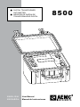 1
1
-
 2
2
-
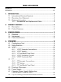 3
3
-
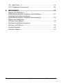 4
4
-
 5
5
-
 6
6
-
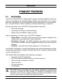 7
7
-
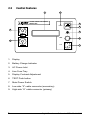 8
8
-
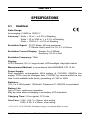 9
9
-
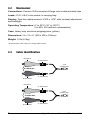 10
10
-
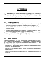 11
11
-
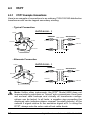 12
12
-
 13
13
-
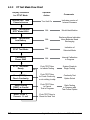 14
14
-
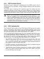 15
15
-
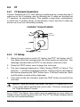 16
16
-
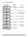 17
17
-
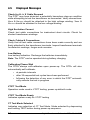 18
18
-
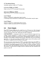 19
19
-
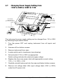 20
20
-
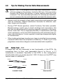 21
21
-
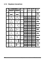 22
22
-
 23
23
-
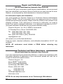 24
24
-
 25
25
-
 26
26
-
 27
27
-
 28
28
-
 29
29
-
 30
30
-
 31
31
-
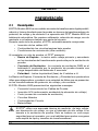 32
32
-
 33
33
-
 34
34
-
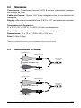 35
35
-
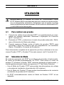 36
36
-
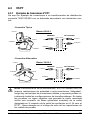 37
37
-
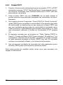 38
38
-
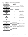 39
39
-
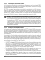 40
40
-
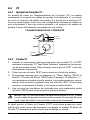 41
41
-
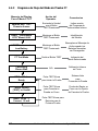 42
42
-
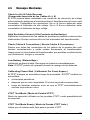 43
43
-
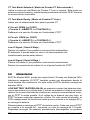 44
44
-
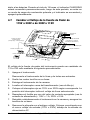 45
45
-
 46
46
-
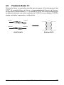 47
47
-
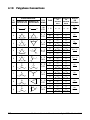 48
48
-
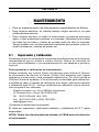 49
49
-
 50
50
-
 51
51
-
 52
52


AEMC 8500 Manual de usuario
- Tipo
- Manual de usuario
- Este manual también es adecuado para
en otros idiomas
- English: AEMC 8500 User manual
Artículos relacionados
Otros documentos
-
DSE DSE7210 Manual de usuario
-
Promax MZ-805 Manual de usuario
-
Amprobe MultiTest 2000 Manual de usuario
-
Hobart 5359D Operation and Maintenance Manual
-
Megger BMM500 Series Manual de usuario
-
CHAUVIN ARNOUX C.A. 6505 Manual de usuario
-
Greenlee DM-60 A Manual de usuario
-
-
Carel PCOXS Manual de usuario
-
Yamaha P-2201 Manual de usuario