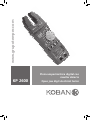
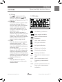
koban KP2600 Manual de usuario
- Categoría
- Multimetros
- Tipo
- Manual de usuario

KP 2600
Pinza amperimétrica digital con
maxilar abierto
Open jaw digit electrical tester
www.grupotemper.com

KP 2600
Pinza amperimétrica digital con maxilar abierto
2
Manual de instrucciones | www.grupotemper.com
Índice
Información de seguridad 3
Significado de los símbolos 3
Precuaciones de seguridad 3
Mantenimiento 4
Descripción general 4
Descripción del panel 4
Instrucciones de uso 7
Especificaciones 10
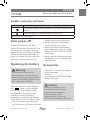
Apagado automático 13
Cambio de pilas 13
Accesorios 13

KP 2600
Pinza amperimétrica digital con maxilar abierto
3
Manual de instrucciones | www.grupotemper.com
Información de
seguridad
Esta pinza amperimétrica ha sido
diseñada de acuerdo a los requisitos
europeos de seguridad IEC1010-1
y IEC1010-2-032 para instrumentos
eléctricos de medida manuales y
para pinzas de corriente. Posee una
categoría de sobrecarga CAT III y un
nivel de polución del tipo 2.
Cumple con los requisitos marcados
por la Directivas de La Comunidad
Europea: 89/336/EEC (Compatibilidad
Electromagnética) y 73/23/EEC (Baja
Tensión) incluidos asimismo en la
siguiente directriz: 93/68/EEC.
De cualquier manera, se debe tener
en cuenta que el uso del medidor
cerca de ruidos producidos por
aparatos eléctricos o la presencia
de campos electromagnéticos
intensos puede alterar el resultado
de la medición del circuito. En
el caso de medición de aparatos
podría también responder a señales
no deseadas que pudieran estar
presentes en el propio circuito que
estamos midiendo.
Haga un uso cuidadoso del aparato y
siga las instrucciones de seguridad.
Significado de los símbolos
Indicación de información
de seguridad importante.
Tensión Peligrosa
Toma de tierra
Doble aislamiento
(Protección Clase II ).
CA – Corriente Alterna.
CC – Corriente Continua.
Pila.
Conforme a las directivas de
la Comunidad Europea
Precauciones de
seguridad
Siga todas las intrucciones de
uso y las precauciones con el fin
de procurar la máxima seguridad
personal y un uso correcto del
medidor así como su mantenimiento
en buenas condiciones de
operatividad.
• Lea con atención las instrucciones
de uso antes de utilizar el
medidor. Preste particular
atención a las PRECAUCIONES,
que le informarán de posibles
riesgos y peligros.
• Antes de cada uso, revise
cuidadosamente su medidor
y las puntas de prueba por si
hubiera algún signo de daño o
anormalidad. Si observa algún
tipo de anormalidad (ej. Puntas de
prueba rotas, carcasas agrietadas,
etc.), no intente realizar ninguna

KP 2600
Pinza amperimétrica digital con maxilar abierto
4
Manual de instrucciones | www.grupotemper.com
medición.
• Mantenga el aparato lejos de la
luz directa del sol, temperaturas
extremas o humedad.
• Nunca toque tierra cuando realice
mediciones eléctricas. No toque
tuberías de metal expuestas,
accesorios, etc., que pudieran ser
un potencial contacto a tierra.
Manténgase aislado del terreno
mediante el uso de ropa seca;
calzado de goma o cualquier otro
material aislante aprobado.
• Tenga siempre cuidado cuando
trabaje con tensiones por encima
de 60V CC o 30V CA RMS.
• Cuando realice mediciones
mantenga los dedos por detrás de
la barrera de prueba.
• Nunca utilice el medidor para
mediciones que pudieran exceder
el máximo valor de entrada de
cualquiera de las funciones..
• Nunca toque cables expuestos,
conexiones o cualquier circuito
vivo a la hora de realizar
mediciones.
Mantenimiento
• Desconecte siempre las puntas
de prueba de todos los circuitos
energizados antes de abrir la
carcasa.
• Compruebe que la tapa trasera de
su medidor está completamente
cerrada y sujeta antes de utilizarlo.
• No utilice productos abrasivos ni
disolventes en el medidor. Para su
limpieza se recomienda el uso de
un trapo húmedo y un detergente
neutro.
• El medidor solo debe ser
reparado y calibrado por técnicos
cualificados.
• No intente calibrar ni usar el
medidor a menos que esté
cualificado para ello.
Descripción general
Este medidor es un instrumento
profesional, posee encendido
automático y diseño de pinza
abierta con 3.999 cuentas. Realiza
mediciones de tension CC y CA,
Corriente Alterna CA, Resistencia,
Capacidad, Frecuencia, ciclos
de trabajo, Prueba de Diodos y
Continuidad. Funciona con pilas.
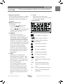
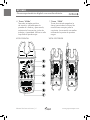
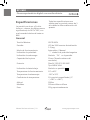
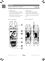
Descripción del panel
1. Pinzas transformadoras
Toman la corriente alterna CA que
fluye a través del conductor.
2. Botón de Retención de datos
Pulsando este botón, la pantalla
retendrá la última lectura y el
símbolo
se mostrará en la LCD
hasta que lo vuelva a pulsar.
Si presiona este botón durante
mas de 2 segundos se encenderá
la pantalla; para apagarla, repita
esta misma operación.

KP 2600
Pinza amperimétrica digital con maxilar abierto
5
Manual de instrucciones | www.grupotemper.com
3. Selector giratorio
Este interruptor giratorio se utiliza
para selecionar las funciones del
medidor y para su encendido y
apagado.
4. Botón de funciones
4.1 F. Func.
En modo
Ω pulse este
botón para seleccionar la
función
o Ω. Los diferentes
símbolos de las funciones se
mostrarán en el LCD.
4.2 R.Modo
Pulse este botón para
seleccionar modo manual o
automático Cuando seleccione
una función que posea ambos
modos automático y manual, el
medidor se pondrá por defecto
en modo automático; púlselo de
nuevo para pasar a odo manual.
Una vez en modo manual,
pulsando este botón podrá
cambiar a la escala más alta y
presionándolo durante más de
tres segundos volver a modo
automático..
4.3 Δ REL
Este botón se utilize para
realizar lecturas relativas. Una
vez pulsado, el símbolo “REL”
aparecerá en el LCD. Guarde el
valor leído en la pantalla como
valor de referencia..
En el modo Relativo, el valor
que se muestra en el LCD es
siempre la diferencia entre el
valor de referencia guardado
y la lectura actual. Si la nueva
lectura coincide con el valor de
referencia, la pantalla marcará
cero.
4.4 % Hz
Este botón se utiliza para
seleccionar la frecuencia y medir
los ciclos de trabajo.
5. Pantalla LCD
Low battery indication
Auto range indication
Relative measurement
indication
Hold data indication
DC input indication
AC input indication
Diode test indication
Continuity indication
Polarity indication
nμF
Capacitance measurement
unit
kMΩ Ohm measurement unit
Hz
Frequency measurement
unit
mVA Current measurement unit
%
Duty cycle measurement
indication

KP 2600
Pinza amperimétrica digital con maxilar abierto
6
Manual de instrucciones | www.grupotemper.com
6. Toma“VΩHz”
Toma de entrada positiva
de tensión, utilizada para la
prueba de diodos y para medir,
resistencia, frecuencia, ciclos de
trabajo y capacidad. Utilice en ella
la punta de prueba roja.
7. Toma“COM”
Toma de entrada negativa (a
tierra) para todos los tipos de
mediciones excepto para la
corriente. La conexión se realiza
utilizando la punta de prueba
negra.
VISTA FRONTAL VISTA POSTERIOR

KP 2600
Pinza amperimétrica digital con maxilar abierto
7
Manual de instrucciones | www.grupotemper.com
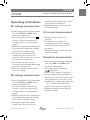
Instrucciones de uso
Medición de corriente CC
1. Conecte las puntas de prueba
negra y la roja a las terminales
COM y VΩHz respectivamente.
2. Gire el selector hacia la posición
deseada V
. Seleccione la escala
de tensión CC o establezca modo
automático.
3. Cuando desconozca la magnitud
de la tensión que va a medir
comience siempre con la escala
más alta.
4. Conecte las puntas de los cables de
prueba en paralelo con el circuito
que va a medir. Tenga cuidado
de no tocar ningún conductor
eléctrico.
5. La polaridad de la conexión de la
punta de prueba roja se indicará
junto con el valor de la tensión.
6. Lea los valores medidos
directamente de la pantalla.
Medición de tensión CA
1. Conecte las puntas de prueba
negra y la roja a las terminales
COM y VΩHz respectivamente.
2. Gire el selector hasta la posición
V~. Seleccione la escala de tensión
deseada AC, o establezca modo
automático.
3. Cuando desconozca la magnitud
de la tensión que va a medir,
empiece siempre con la escala más
alta.
4. Conecte las puntas de los cables de
prueba en paralelo con el circuito
que va a medir. Tenga cuidado
de no tocar ningún conductor
eléctrico.
5. Lea los valores medidos
directamente de la pantalla.
Medición de corriente CA
1. Coloque el selector en la posición
A~.
2. Para sujetar un solo conductor
en las pinzas transformadoras,
asegúrese de que la pinza está
alrededor del conductor.
3. Lea los valores medidos en la
pantalla.
Medición de resistencia
1. Conecte las puntas de prueba
negra y la roja a las terminales
COM y VΩHz respectivamente.
2. Coloque el selector en la posición
o Ω.
3. Pulse el botón de F.FUNC. para
seleccionar Ω.
4. Si la Resistencia que vamos a
medir excede el máximo valor de la
escala seleccionada o la entrada no
está conectada , la indicación de
sobrecarga “OL” aparecerá en la
pantalla y deberá seleccionar una
escala mayor.
5. Lea los valores medidos en la
pantalla.

KP 2600
Pinza amperimétrica digital con maxilar abierto
8Manual de instrucciones | www.grupotemper.com
Nota:
1. Si la resistencia que vamos a medir
excede el máximo valor de la
escala seleccionada o la entrada no
está conectada , la indicación de
sobrecarga “OL” aparecerá en la
pantalla y deberá seleccionar una
escala mayor.
2. Cuando compruebe la Resistencia
de un circuito, asegúrese de que
haya sido desconectado de toda
fuente de potencia y que todos los
condensadores estén totalmente
descargados.
3. Para resistencias por encima de
1MΩ, al medidor le llevará unos
segundos realizar una lectura
estable. Esto es normal cuando
medimos resistencias muy altas.
4. Cuando la entrada no está
conectada, por ej. en circuitos
abiertos, aparecerá en la pantalla el
símbolo “OL” de sobrecarga.
Medición de diodos
1. Conecte las puntas de prueba
negra y la roja a las terminales
COM y VΩHz respectivamente.
2. Gire el selector a la posición
o Ω.
3. Pulse el botón F.FUNC. para
seleccionar
.
4. La punta de prueba roja debe estar
conectada al ánodo y la punta
negra al cátodo del diodo.
5. La caída de tensión típica debería
ser sobre 0.6V para diodos
de silicona y 0.3V para los de
germanio.
6. Si el diodo está sesgado, invertido
o hay un circuito abierto la
pantalla mostrará el símbolo
“OL”.
Test de continuidad
1. Conecte las puntas de prueba
negra y la roja a las terminales
COM y VΩHz respectivamente.
2. Coloque el selector en la posición
o Ω.
3. Pulse el botón F.FUNC. para
seleccionar
.
4. Si existe continuidad (ej., una
Resistencia menor de 30Ω) el
avisador acústico de continuidad
sonará.
Medición de capacitancia
1. Conecte las puntas de prueba
negra y la roja a las terminales
COM y VΩHz respectivamente.
2. Gire el selector a la posición
.
Conecte las puntas de prueba a
través del condensador que va a
medir y asegúrese de observar la
polaridad de la conexión.(Nota: La
polaridad de la punta de prueba
roja es positiva “+”).
3. Lea los valores medidos en la
pantalla.

KP 2600
Pinza amperimétrica digital con maxilar abierto
9
Manual de instrucciones | www.grupotemper.com
Medición de la frecuencia
Nota:
La tension de entrada debe estar
entre 1V y10V RMS AC. Si la tension
es mayor de 10V RMS. Las lecturas
no serán precisas.
1. Conecte las puntas de prueba
negra y la roja a las terminales
COM y VΩHz respectivamente.
2. Gire el selector a la posición Hz.
3. Pulse el botón % Hz. Para
seleccionar el modo frecuencia y
conecte las puntas de los cables de
prueba en paralelo con el circuito
que va a medir. Tenga cuidado
de no tocar ningún conductor
eléctrico.
4. La amplitud de la señal debe ser
mayor que el nivel de sensibilidad.
5. Determine que el nivel de amplitud
de la señal que va a medir no es
mayor que el límite de entrada de
tensión. (250V CA/CC RMS).
6. Lea los valores medidos en la
pantalla.
Test de ciclo de trabajo
1. Conecte las puntas de prueba
negra y la roja a las terminales
COM y VΩHz respectivamente.
2. Gire el selector a la posición Hz.
3. Pulse el botón % Hz. Para
seleccionar el modo frecuencia y
conecte las puntas de los cables de
prueba en paralelo con el circuito
que va a medir. Tenga cuidado
de no tocar ningún conductor
eléctrico.
4. Lea los valores medidos en la
pantalla.

KP 2600
Pinza amperimétrica digital con maxilar abierto
10
Manual de instrucciones | www.grupotemper.com
Especificaciones
La precisión se da en ±(% de la
lectura + número de dígitos menos
significativos) de 18℃ a 28℃, con
una humedad relativa de hasta un
80%.
Todas las especificaciones son
válidas para un periodo menor de 1
año desde la última calibración del
aparato.
Tensión Máxima: CAT III 600V.
Pantalla: LCD de 3999 cuentas. Actualización
2-3/seg.
Modo de funcionamiento: Automático / Manual
Indicación de polaridad: “-”símbolo de polaridad negativa
Indicación de sobrecarga: Símbolo “OL” en la pantalla
Capacidad de la pinza: 12mm (Tamaño máximo del
conductor)
Potencia: Pilas 9V IEC 6F22 JIS 006P
Tipo NEDA 1604.
Indicación de batería baja:
Símbolo en pantalla
Temperatura de funcionamiento: 0℃ a 40℃
Temperatura de almacenaje: -10℃ a 50℃
Coeficiente de temperatura: 0.1×precisón especificada) /℃
( <18℃ o >28℃ )
Altitud: 2000m
Medidas: 192mm×68mm×43mm
Peso: 230g. aproximadamente
General

KP 2600
Pinza amperimétrica digital con maxilar abierto
11
Manual de instrucciones | www.grupotemper.com
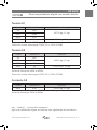
Tensión CC
Escala Resolución Precisión
4V 1mV
±0.7% rdg ± 1 dgt
40V 10mV
400V 0.1V
1000V 1V ±0.8% rdg ± 3 dgt
Impedancia de entrada: 10MΩ
Protección contra sobrecargas: 1000V CC or 700V CA RMS
Tensión CA
Escala Resolución Precisión
4V 1mV
±0.8% rdg ± 5 dgt
40V 10mV
400V 0.1V
700V 1V ±1.0% rdg ± 10 dgt
Impedancia de entrada: 10MΩ
Escala de frecuencia: 40Hz to 400Hz.
Protección contra sobrecargas: 1000V CC or 700V CA RMS
Corriente CA
Escala Resolución Precisión
200V 0.1A ±3.0% rdg ± 3 dgt
Protección contra sobrecargas: 240A durante 60 segundos máximo.
Escala de frecuencia: 50Hz to 400Hz.
rdg: “reading” , lectura del instrumento.
dgt: es la cantidad de dígitos de la última cifra significativa de la medición.

KP 2600
Pinza amperimétrica digital con maxilar abierto
12
Manual de instrucciones | www.grupotemper.com
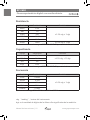
Resistencia
Escala Resolución Precisión
400Ω 0.1Ω
±1.2% rdg ± 1 dgt
4kΩ 1Ω
40kΩ 10Ω
400kΩ 0.1kΩ
4MΩ 1kΩ
40MΩ 10kΩ ±2.0% rdg ± 3 dgt
Protección contra sobrecargas: 250V CC o RMS CA para todas las escalas.
Capacitancia
Escala Resolución Precisión
40nF 10pF
±4.0% rdg ± 10 dgt400nF 0.1nF
4μF 1nF
40μF 10nF -
Protección contra sobrecargas: 250V CC o RMS CA para todas las escalas.
Frecuencia
Escala Resolución Precisión
40Hz 0.01Hz
±2.0% rdg ± 1 dgt
400Hz 0.1Hz
4kHz 1Hz
40kHz 10Hz
100kHz 0.1kHz
Measurement range: 1V to 10V rms. 10Hz to 100kHz.
rdg: “reading” , lectura del instrumento.
dgt: es la cantidad de dígitos de la última cifra significativa de la medición.

KP 2600
Pinza amperimétrica digital con maxilar abierto
13
Manual de instrucciones | www.grupotemper.com
Señal audible de continuidad y diodo
Range Description
Si existe continuidad (aprox. menos de 30Ω), el avisador
acústico sonará.
Muestra aprox. Hacia dónde va la tension del diodo.
Ciclo de trabajo: del 0.1% hasta 99.9%
Apagado automático
Gracias a la función de apagado
automático se alarga la vida de
las pilas. Si no se realiza ninguna
operación ni cambio de escala en
30 minuto, el medidor se apagará
automáticamente. Para encenderlo
de nuevo gire el selector o pulse uno
de los botones de funciones.
Cambio de pilas
Precaución
Para evitar descargas o daños
personales, desconecte las puntas
de prueba de cualquier señal de
entrada antes de cambiar las pilas.
Reemplácelas únicamente por
otras del mismo tipo.
Cuando el medidor eléctrico muestre
el símbolo “
” o la luz trasera
no sea muy luminosa, se deben
cambiar las pilas para mantener un
uso correcto. Siga las siguientes
instrucciones para su sustitución:
1. Coloque el selector en la posición
OFF. Desconecte las puntas de
prueba de cualquier fuente viva
y retírelas de las terminales de
entrada.
2. Quite los tornillos de la tapa de las
pilas y ábrala.
3. Cámbielas por unas nuevas de
voltaje 9- (IEC 6F22 JIS 006P tipo
NEDA 1604).
4. No utilice el multímetro a menos
que la tapa de las baterías
está perfectamente cerrada y
atornillada.
Accesorios
• Manual de instrucciones
• Juego de puntas de prueba
• Pila de 9 voltios (IEC 6F22 JIS 006P
NEDA 1604).
Precaución
El uso de este aparato en
ambientes con un campo
electromagnético de radio
frecuencia muy potente( aprox.
3V/m ) puede influir en la
precisión de sus mediciones.

14
Instructions manual | www.grupotemper.com
KP 2600
Open jaw digit electrical tester
Contents
Safety information 15
Symbol explanation 15
Safety precautions 15
Maintenance 16
General description 16
Panel description 16
Operating instructions 19
Specifications 22
Auto power off 25
Replacing the battery 25
Accessories 25

15
Instructions manual | www.grupotemper.com
KP 2600
Open jaw digit electrical tester
Safety information
The open jaw digit electrical tester
has been designed according to
IEC1010 – 1 and IEC1010 – 2 – 032
concerning safety requirements for
electrical measuring instruments and
hand – held current clamps with an
overvoltage category (CAT III) and
pollution 2.
The open jaw digit electrical tester
complies with the requirements
of the following European
Community Directives: 89/336/EEC (
Electromagnetic Compatibility ) and
73/23/EEC (Low Voltage) as amended
by 93/68/EEC (CE Marking).
However, electrical noise or intense
electromagnetic fields in the vicinity
of the equipment may disturb the
measurement circuit. Measuring
instruments will also respond to
unwanted signals that may be
present within the measurement
circuit.
Users should exercise care and take
appropriate precautions to avoid
misleading.
Symbol explanation
Indicates important safety
information.
Dangerous voltage may be
present.
Earth ground.
Double insulation
(Protection class II).
AC – Alternating Current.
DC – Direct current.
Battery.
Conforms to European
Union directives.
Safety precautions
Follow all safety and operating
instructions to ensure maximum
personal safety during the operation
and to ensure the meter is used
safely and is kept in good operating
condition.
• Read these operating instructions
thoroughly and completely
before operating your meter. Pay
particular attention to WARNINGS,
which will inform you of
potentially dangerous procedures.
The instructions in these warnings
must be followed.
• Always inspect your meter and
test leads for any sign of damage
or abnormality before every use.
If any abnormal conditions exist
(i.e. broken test leads, cracked
cases, display not reading, etc.),
do not attempt to take any
measurements.

16
Instructions manual | www.grupotemper.com
KP 2600
Open jaw digit electrical tester
• Do not expose the instrument
to direct sunlight, extreme
temperature or moisture.
• Never ground yourself when
taking electrical measurements.
Do not touch exposed metal
pipes, outlets, fixtures, etc., which
might be at ground potential.
Keep your body isolated from
ground by using dry clothing;
rubber shoes, rubber mat, or any
approved insulating material.
• You always are careful when
working with voltages above 60V
dc or 30V ac rms. Keep fingers
behind the probe barriers while
measuring.
• Never use the meter to measure
voltages that might exceed the
maximum allowable input value of
any function.
• Never touch exposed wiring,
connections or any live circuit
when attempting to take
measurements.
Maintenance
• Before opening the case, always
disconnect test leads from all
energized circuits.
• Never use the meter unless the
back cover is in place and fastened
completely.
• Do not use abrasives or solvents
on the meter. To clean it using a
damp cloth and mild detergent
only.
• Qualified and trained service
technicians should only perform
calibration and repair of the meter.
• Do not attempt calibration or
service unless trained and another
person capable of rendering first
aid and resuscitation is present.
General description
The meter is an autorange
professional open jaw digit electrical
tester with 3999 counts. For
measuring DC and AC voltage, AC
current, Resistance, Capacitance,
Frequency, duty cycle, Diode
and Continuity Test with battery
operated.
Panel description
1. Transformer jaws
Pick up the AC current flowing
through the conductor.
2. Hold button
When this button is pushed, the
display will keep the last reading
and symbol
will appear on the
LCD until pushing it again
When this button is pressed more
than two second, the light of
display is on until pressing it more
than two second again.
3. Rotary switch
This Rotary Switch is used to select
functions and power supply of the
meter on or off.
4. Function button

17
Instructions manual | www.grupotemper.com
KP 2600
Open jaw digit electrical tester
4.1 F. Func.
In
Ω range, press this
button to select or
or Ω
function. Different symbol of
function will appear on the LCD.
4.2 R.Range
Press this button to select auto
and manual range. When a
function with auto and manual
mode is selected, the meter
enters auto range at first. To
change to manual range, push
this button once.
When the meter operates in
manual ranging mode, push this
button to change range to the
higher one and hold this button
for more than 3 seconds to
return to auto range mode.
4.3 Δ REL
Push the button to get relative
measurement mode, “REL”
annunciate display on LCD. But
store the displayed reading as a
reference value.
In the Relative mode, the value
shown on the LCD is always the
difference between the stored
reference value and the present
reading. If the new reading is the
same as the reference value, the
display will be zero.
4.4 % Hz
Push the button is used to
select frequency or duty cycle
measurement.
5. LCD display
cfg
Low battery indication
Auto range indication
Relative measurement
indication
Hold data indication
DC input indication
AC input indication
Diode test indication
Continuity indication
Polarity indication
nμF
Capacitance measurement
unit
kMΩ Ohm measurement unit
Hz
Frequency measurement
unit
mVA Current measurement unit
%
Duty cycle measurement
indication

18
Instructions manual | www.grupotemper.com
KP 2600
Open jaw digit electrical tester
6. “VΩHz” jack
This is positive input terminal for
volt, diode, resistance,frequency,
duty cycle and capacitance
measurement connection is made
to it using the red test lead.
7. “COM” jack
This is negative (ground) input
terminal for all measurement
modes except current. Connection
is made to it using the black test
lead.
LAYOUT (FORWARD) LAYOUT (BACKWARD)

19
Instructions manual | www.grupotemper.com
KP 2600
Open jaw digit electrical tester
Operating instructions
DC voltage measurement
1. Insert the black and red test leads
into the COM and VΩHz input
terminals respectively.
2. Set rotary switch at desired V
position. Select the desired DC
voltage range, or set automatic
range.
3. When the magnitude of voltage to
be measured is unknown, always
start with the highest range.
4. Connect the test lead tips in
parallel with the circuit to be
measured. Be careful not to touch
any electrical conductors.
5. The polarity of the red lead
connection will be indicated along
with the voltage value.
6. Read the measure result directly
from the display.
DC voltage measurement
1. Insert the black and red test leads
into the COM and VΩHz input
terminals respectively.
2. Set rotary switch at desired V~
position. Select the desired AC
voltage range, or set automatic
range.
3. When the magnitude of voltage to
be measured is unknown, always
start with the highest range.
4. Connect the test lead tips in
parallel with the circuit to be
measured. Be careful not to touch
any electrical conductors.
5. Read the measure result directly
from the display.
AC current measurement
1. Set the rotary switch at A~
position.
2. To clamp one conductor in
Transformer jaws only, making
sure that the jaw is around the
conductor.
3. Read the measure result directly
from the display.
Resistance measurement
1. Insert the black and red test leads
into the COM and VΩHz input
terminals respectively.
2. Set rotary switch at desired
Ω position.
3. Push F.FUNC. button to select Ω.
4. If the resistance being measured
exceeds the maximum value of the
range selected or the input is not
connected, an overrange indication
“OL” will be display and the
higher range has to be selected.
5. Read the measure result directly
from the display.

20Instructions manual | www.grupotemper.com
KP 2600
Open jaw digit electrical tester
Note:
1. If the resistance being measured
exceeds the maximum value of the
range selected or the input is not
connected, an overrange indication
“OL”will be displayed.Set rotary
switch at desired V~ position.
Select the desired AC voltage
range, or set automatic range.
2. When checking in-circuit
resistance, be sure the circuit
under test has all power removed
and that all capacitors have been
discharged fully.
3. For measuring resistance above
1MΩ, the meter may take a few
seconds to get stable reading.
This is normal for high resistance
measurements.
4. When the input is not connected,
i.e. at open circuit, the figure
“OL” will be displayed for the
overrange condition.
Diode measurement
1. Insert the black and red test leads
into the COM and VΩHz input
terminals respectively.
2. Set rotary switch at desired
Ω position.
3. Push F.FUNC. button to select
.
4. The red lead should be connected
to the anode and the black lead to
the cathode of the diode.
5. The typical voltage drop should be
about 0.6V for silicon diode or 0.3V
for germanium diode.
6. If the diode is reverse biased or
there is an open circuit the reading
displayed will be “OL”.
Continuity testing
1. Insert the black and red test leads
into the COM and VΩHz input
terminals respectively.
2. Set rotary switch at desired
Ω position.
3. Push F.FUNC. button to select
.
4. If continuity exists (i.e., resistance
less than 30Ω) built – in buzzer will
sound.
Capacitance measurement
1. Insert the black and red test leads
into the COM and VΩHz input
terminals respectively.
2. Turn the rotary switch to
position.
Connect test leads across the
capacitor under measurement
and be sure that the polarity of
connection is observed (Note: The
polarity of the red lead connection
is positive “+”).
3. Read the measure result directly
from the display.

21
Instructions manual | www.grupotemper.com
KP 2600
Open jaw digit electrical tester
Measuring frequency
Note:
The input voltage should be between
1V and 10V rms. ac. If the voltage is
more than 10V rms. Reading may be
out of the accuracy range.
1. Insert the black and red test leads
into the COM and VΩHz input
terminals respectively.
2. Set rotary switch at desired Hz
position.
3. Push % Hz. button to select
frequency mode and connect
the test lead tips in parallel with
the circuit to be measured. Be
careful not to touch any electrical
conductors.
4. The signal amplitude must also be
greater than the sensitivity level.
5. Determine that the amplitude level
of the signal to be measured is not
greater than the input voltage limit
(250V DC/AC rms.).
6. Read the measure result directly
from the display.
Duty cycle test
1. Insert the black and red test leads
into the COM and VΩHz input
terminals respectively.
2. Set rotary switch at desired Hz
position.
3. Push % Hz. button to select %
mode and connect the test lead
tips in parallel with the circuit to
be measured. Be careful not to
touch any electrical conductors.
The typical voltage drop should be
about 0.6V for silicon diode or 0.3V
for germanium diode.
4. Read the measure result directly
from the display.

22
Instructions manual | www.grupotemper.com
KP 2600
Open jaw digit electrical tester
Specifications
Accuracy is given as ±(% of reading
+ number of least significant
digits) at 18℃ to 28℃, with relative
humidity up to 80%.
All specifications assume less than 1
year since calibration.
Maximum voltage: CAT III 600V.
Display: LCD3999 counts. updates 2-3/sec.
Ranging method: Auto / Manual
Polarity indication: “-”displayed for negative polarity
Overrange indication: Only figure “OL” on the display
Jaw capability: 12mm (Max conductor size)
Power: Battery 9V IEC 6F22 JIS 006P
NEDA 1604 type.
Low battery:
appears on the display
Operating: 0℃ to 40℃
Storage temperature: -10℃ to 50℃
Temperature coefficient: 0.1×specified accuracy) /℃
( <18℃ or >28℃ )
Altitude: 2000m
Size: 192mm×68mm×43mm
Weight: Approx. 230g.
General

23
Instructions manual | www.grupotemper.com
KP 2600
Open jaw digit electrical tester
DC voltage
Range Resolution Accuracy
4V 1mV
±0.7% of rdg ± 1 digit40V 10mV
400V 0.1V
1000V 1V ±0.8% of rdg ± 3 digits
Input impedance: 10MΩ
Overload Protection: 1000V DC or 700V AC RMS
AC voltage
Range Resolution Accuracy
4V 1mV
±0.8% of rdg ± 5 digits40V 10mV
400V 0.1V
700V 1V ±1.0% of rdg ± 10 digits
Input impedance: 10MΩ
Frequency range: 40Hz to 400Hz.
Overload Protection: 1000V DC or 700V AC RMS
AC current
Range Resolution Accuracy
200V 0.1A ±3.0% of rdg ± 3 digits
Overload Protection: 240 A for 60 seconds maximum

24
Instructions manual | www.grupotemper.com
KP 2600
Open jaw digit electrical tester
Resistance
Range Resolution Accuracy
400Ω 0.1Ω
±1.2% of rdg ± 1 digit
4kΩ 1Ω
40kΩ 10Ω
400kΩ 0.1kΩ
4MΩ 1kΩ
40MΩ 10kΩ ±2.0% of rdg ± 3 digits
Overload Protection: 250V DC or RMS AC for all ranges.
Capacitance measurement
Range Resolution Accuracy
40nF 10pF
±4.0% of rdg ± 10 digits400nF 0.1nF
4μF 1nF
40μF 10nF -
Overload Protection: 250V DC or RMS AC for all ranges.
Frequency measurement
Range Resolution Accuracy
40Hz 0.01Hz
±2.0% of rdg ± 1 digit
400Hz 0.1Hz
4kHz 1Hz
40kHz 10Hz
100kHz 0.1kHz
Measurement range: 1V to 10V rms. 10Hz to 100kHz.

25
Instructions manual | www.grupotemper.com
KP 2600
Open jaw digit electrical tester
Audible continuity and diode
Range Description
If continuity exists (about less than 30Ω), built-in buzzer will
sound.
Show the approx. Forward voltage of the diode.
Duty cycle: 0.1% to 99.9%
Auto power off
To extend the battery life, Auto
Power Off function is provided. If no
key operations of range changing
happen about 30 minutes, the meter
will be turned off automatically. To
turn it on, rotate the rotary switch or
push any function buttons only.
Replacing the battery
Warning
To avoid electrical shock or
personal injury, remove the test
leads and any input signals before
replacing the battery. Replace only
with same type of battery.
When the electrical tester displays
the “
” mark or the backlight
be not very lit, the battery must
be replaced to maintain proper
operation. Use the following
procedure to replacing the battery:
1. The Rotary Switch is used to select
OFF. Disconnect test leads from
any live source and remove the test
leads from the input terminals.
2. Remove screws on the battery
cover and open the cover.
3. Remove the exhausted battery
and replace with a new 9-voltage
battery (IEC 6F22 JIS 006P NEDA
1604 type).
4. Never use the multimeter unless
the battery cover is in place and
fastened fully.
Accessories
• Operator’s instruction manual
• Set of test leads
• Gift box
• 9 volt battery (IEC 6F22 JIS 006P
NEDA 1604 type).
Caution
Using this appliance in an
environment with a strong
radiated radio-frequency
electromagnetic field
(approximately 3V/m) may
influence its measuring accuracy.

26
Instructions manual | www.grupotemper.com
KP 2600
Open jaw digit electrical tester

TEMPER ENERGY INTERNATIONAL S.L.
garantiza este aparato por 2 años ante
todo defecto de fabricación. Para hacer
válida esta garantía, es imprescindible
presentar con este resguardo el ticket o
factura de compra.
TEMPER ENERGY INTERNATIONAL S.L.
guarantees this device during 2 years
against any manufacturing defect. For
warranty service, you must present this
receipt with the purchase receipt or
invoice.
TEMPER ENERGY INTERNATIONAL
S.L. garantit cet apareil pour le durée
de 2 annèes contre tout défault de
fabrication. Pour le service de garantie,
vous devez présenter ce reçu avec du
ticket de caisse ou la facture.
TEMPER ENERGY INTERNATIONAL S.L.
garantía este aparelho contra defeitos
de fábrica ate 2 anos. Para o serviço
de garantia, você deve apresentar este
recibo com o recibo de compra ou
fatura.
GARANTÍA • WARRANTY
GARANTIE • GARANTIA
2
años
years
années
anos
Ref. Art.
Nº serie / Serial number
Nombre / Name / Nom / Nombre
Fecha de venta / Date of purchase
Date de vente / Data de venda
Sello establecimiento vendedor / Dealer stamp
Cachet du commercant / Cambo da firma

TEMPER ENERGY INTERNATIONAL S.L.
Polígono industrial de Granda, nave 18
33199 • Granda - Siero • Asturias
Teléfono:
902 201 292
Fax: 902 201 303
Email: info@grupotemper.com
Una empresa
del grupo
-
 1
1
-
 2
2
-
 3
3
-
 4
4
-
 5
5
-
 6
6
-
 7
7
-
 8
8
-
 9
9
-
 10
10
-
 11
11
-
 12
12
-
 13
13
-
 14
14
-
 15
15
-
 16
16
-
 17
17
-
 18
18
-
 19
19
-
 20
20
-
 21
21
-
 22
22
-
 23
23
-
 24
24
-
 25
25
-
 26
26
-
 27
27
-
 28
28


koban KP2600 Manual de usuario
- Categoría
- Multimetros
- Tipo
- Manual de usuario
en otros idiomas
- English: koban KP2600 User manual
Artículos relacionados
-
koban KMD-03 El manual del propietario
-
-
-
-
-
-
-
-
-
Otros documentos
-
KNOVA KN 8058 El manual del propietario
-
KPS PA440 El manual del propietario
-
Steren MUL-030 El manual del propietario
-
Innova 3340 Guía del usuario
-
-
Amprobe HD160C Digital Multimeter Manual de usuario
-
Promax MD-200C Manual de usuario
-
Milwaukee 2239-21NST Manual de usuario
-
-
Laserliner MultiMeter-Compact El manual del propietario