Simplicity SEARS ZTS 7500 RIDER, 26 HP KOHLER W/50" MOWER Manual de usuario
- Categoría
- Cortadoras de césped
- Tipo
- Manual de usuario
Este manual también es adecuado para

Operator’s Manual
ZTS 7500
Zero-Turn Rear Engine Rider with Electric Start
Model No.
107.28791 (26 HP Kohler Engine with 50” Mower)
CAUTION: Before using this product, read
the manual and follow all its Safety Rules
and Operating Instructions.
For answers to your questions about this
product, call:
1-800-659-5917
Sears Craftsman Help Line
5 am - 5 pm, Mon - Sat
Sears, Roebuck and Co., Hoffman Estates, IL 60179 U.S.A.
Visit our Craftsman website: www.sears.com/craftsman
TP 899-4871-01-CZ-C
7102360
Revision 01
Nota: Una traducción en español de este Manual
del Operador puede encontrarse en la página 33.

TABLE OF CONTENTS
WARRANTY
2
Warranty Statement.....................................................2
Safety Rules & Information.........................................3
Identification Numbers................................................8
Optional Accessories..................................................8
Literature Package Contents......................................8
Pre-Operation...............................................................9
Operation....................................................................10
Maintenance...............................................................17
Service & Adjustments .............................................25
Storage .......................................................................29
Specifications ............................................................29
Troubleshooting.........................................................30
Spanish Operator’s Manual ......................................33
Repair Parts .........................................................PTS-1
Hardware & Torque Specifications...................PTS-36
Repair Protection Agreement........Inside Back Cover
Service Numbers........................................Back Cover
LIMITED WARRANTY ON CRAFTSMAN RIDING EQUIPMENT
For two (2) years from the date of purchase, if this Craftsman riding equipment is maintained, lubricated and tuned up
according to the instructions in the owner's manual, Sears will repair or replace free of charge any parts that are
found to be defective in material or workmanship according to the guidelines of coverage listed below. Sears will also
provide free labor for these applicable warrantied parts for the two full years. During the first 30 days of purchase,
there will be no charges to service the product at your home for issues covered by this warranty. (See exclusions
below). For your convenience, IN HOME warranty service will still be available after the first 30 days of purchase, but
a trip charge will apply. This charge will be waived if the Craftsman product is dropped off at an authorized Sears
location. For the nearest authorized Sears location, please call 1-800-MY-HOME. This warranty applies only while this
product is within the United States.
LIMITED WARRANTY ON BATTERY
For ninety (90) days from date of purchase, if any battery included with this riding equipment proves defective in
material or workmanship and our testing determines the battery will not hold a charge, Sears will replace the battery
at no charge. During the first 30 days of purchase, there will be no charges to replace the battery at your HOME. After
first 30 days, for your convenience, IN-HOME warranty service will still be available but a trip charge will apply. This
charge will be waived if the Craftsman product is dropped off at an authorized Sears location. FOR THE NEAREST
AUTHORIZED LOCATION, PLEASE CALL 1-800-4-MY-HOME. This battery warranty applies only while this product
is within the United States.
This warranty gives you specific legal rights, and you may also have other rights which vary from state to state.
Sears, Roebuck and Co., Dept. 817WA, Hoffman Estates, IL 60179
THIS WARRANTY DOES NOT COVER:
• Expendable items which become worn during normal
use, including but not limited to blades, spark plugs,
air cleaners, belts, and oil filters.
• Standard maintenance servicing, oil changes, or
tune-ups.
• Tire replacement or repair caused by punctures from
outside objects, such as nails, thorns, stumps, or
glass.
• Repairs necessary because of operator abuse,
including but not limited to, damage caused by towing
objects beyond the capability of the riding equipment,
impacting objects that bend the frame or crankshaft,
or over-speeding the engine.
• Repairs necessary because of operator negligence,
including but not limited to, electrical and mechanical
damage caused by improper storage, failure to use
the proper grade and amount of engine oil, failure to
keep the deck clear of flammable debris, or failure to
maintain the equipment according to the instructions
contained in the owner's manual.
• Engine (fuel system) cleaning or repairs caused by
fuel determined to be contaminated or oxidized
(stale). In general, fuel should be used within 30 days
of its purchase date.
• Normal deterioration and wear of the exterior of the
exterior finishes, or product label replacement.
• Riding equipment used for commercial or rental
purposes.
Nota: Una traducción en español de este Manual del Operador puede encontrarse en la página 33.
NOTE: In this manual, “left” and “right” are referred to as seen from the operating position.

3
SAFETY RULES
GENERAL OPERATION
1. Read, understand, and follow all instructions in the
manual and on the unit before starting.
2. Do not put hands or feet near rotating parts or under
the machine. Keep clear of the discharge opening at
all times.
3. Only allow responsible adults, who are familiar with
the instructions, to operate the unit (local regulations
can restrict operator age).
4. Clear the area of objects such as rocks, toys, wire,
etc., which could be picked up and thrown by the
blade(s).
5. Be sure the area is clear of other people before
mowing. Stop the unit if anyone enters the area.
6. Never carry passengers.
7. Do not mow in reverse unless absolutely necessary.
Always look down and behind before and while
travelling in reverse.
8. Never direct discharge material toward anyone. Avoid
discharging material against a wall or obstruction.
Material may ricochet back toward the operator. Stop
the blade(s) when crossing gravel surfaces.
9. Do not operate the machine without the entire grass
catcher, discharge guard (deflector), or other safety
devices in place and operational.
10. Slow down before turning.
11. Never leave a running unit unattended. Always
disengage the blades (PTO), set parking brake, stop
engine, and remove keys before dismounting.
12. Disengage blades (PTO) when not mowing. Shut off
engine and wait for all parts to come to a complete
stop before cleaning the machine, removing the grass
catcher, or unclogging the discharge guard.
13. Operate the machine only in daylight or good artificial
light.
14. Do not operate the unit while under the influence of
alcohol or drugs.
15 Watch for traffic when operating near or crossing
roadways.
16. Use extra care when loading or unloading the unit
into a trailer or truck.
17. Always wear eye protection when operating this unit.
18. Data indicates that operators, age 60 years and
above, are involved in a large percentage of power
equipment-related injuries. These operators should
evaluate their ability to operate the equipment safely
enough to protect themselves and others from injury.
19. Follow the manufacturer’s recommendations for wheel
weights or counterweights.
20. Keep in mind the operator is responsible for accidents
occurring to other people or property.
21. All drivers should seek and obtain professional and
practical instruction.
22. Always wear substantial footwear and trousers.
Never operate when barefoot or wearing sandals.
23. Before using, always visually check that the blades
and blade hardware are present, intact, and secure.
Replace worn or damaged parts.
24. Disengage attachments before: refueling, removing
an attachment, making adjustments (unless the
adjustment can be made from the operator’s
position).
25. When the machine is parked, stored, or left
unattended, lower the cutting means unless a positive
mechanical lock is used.
26. Before leaving the operator’s position for any reason,
engage the parking brake (if equipped), disengage
the blades (PTO), stop the engine, and remove the
key.
27. To reduce fire hazard, keep the unit free of grass,
leaves, & excess oil. Do not stop or park over dry
leaves, grass, or combustible materials.
28. It is a violation of California Public Resource Code
Section 4442 to use or operate the engine on or near
any forest-covered, brush-covered, or grass-covered
land unless the exhaust system is equipped with a
spark arrester meeting any applicable local or state
laws. Other states or federal areas may have similar
laws.
29. OSHA regulations may require the use of hearing
protection when exposed to sound levels greater than
85 dBA for an 8 hour time period.
Read these safety rules and follow them closely. Failure to obey these rules could result in loss of control
of unit, severe personal injury or death to you, or bystanders, or damage to property or equipment.
This mowing deck is capable of amputating hands and feet and throwing objects.
The triangle in text signifies important cautions or warnings which must be followed.
TRANSPORTING AND STORAGE
1. When transporting the unit on an open trailer, make
sure it is facing forward, in the direction of travel. If
the unit is facing backwards, wind lift could damage
the unit.
2. Always observe safe refueling and fuel handling
practices when refueling the unit after transportation
or storage.
3. Never store the unit (with fuel) in an enclosed poorly
ventilated structure. Fuel vapors can travel to an
ignition source (such as a furnace, water heater, etc.)
and cause an explosion. Fuel vapor is also toxic to
humans and animals.
4. Never store the unit or fuel container inside where
there is an open flame or pilot light, such as in a
water heater. Allow unit to cool before storing.
CAUTION
This machine produces sound levels in
excess of 85 dBA at the operator’s ear and
can cause hearing loss though extended
periods of exposure.
Wear hearing protection when operating this
machine.

CHILDREN
Tragic accidents can occur if the operator is not alert to the
presence of children. Children are often attracted to the unit
and the mowing activity. Never assume that children will
remain where you last saw them.
1. Keep children out of the mowing area and under the
watchful care of another responsible adult.
2. Be alert and turn unit off if children enter the area.
3. Before and during reverse operation, look behind and
down for small children.
4. Never carry children, even with the blade(s) off. They
may fall off and be seriously injured or interfere with
safe unit operation. Children who have been given
rides in the past may suddenly appear in the mowing
area for another ride and be run over or backed over
by the machine.
5. Never allow children to operate the unit.
6. Use extra care when approaching blind corners,
shrubs, trees, or other objects that may obscure
vision.
EMISSIONS
1. Engine exhaust from this product contains chemicals
known, in certain quantities, to cause cancer, birth
defects, or other reproductive harm.
2. Look for the relevant Emissions Durability Period and
Air Index information on the engine emissions label.
SLOPE OPERATION
Slopes are a major factor related to loss-of-control and tip-
over accidents, which can result in severe injury or death.
Operation on all slopes requires extra caution. If you cannot
back up the slope or if you feel uneasy on it, do not operate
on it.
Control of a walk-behind or ride-on machine sliding on a
slope will not be regained by the application of the brake.
The main reasons for loss of control are: insufficient tire
grip on the ground, speed too fast, inadequate braking, the
type of machine is unsuitable for its task, lack of awareness
of the ground conditions, incorrect hitching and load
distribution.
1. Mow up and down the face of slopes, not across.
2. Watch for holes, ruts, or bumps. Uneven terrain could
overturn the unit. Tall grass can hide obstacles.
3. Choose a slow speed so that you will not have to stop
or change speeds while on the slope.
4. Do not mow on wet grass. Tires may loose traction.
5. Avoid starting, stopping, or turning on a slope. If tires
lose traction (i.e. machine stops forward motion on a
slope), disengage the blade(s) (PTO) and drive slow
off the slope.
6. Keep all movement on slopes slow and gradual. Do
not make sudden changes in speed or direction,
which could cause the machine to rollover.
7. Use extra care while operating machines with grass
catchers or other attachments; they can affect the
stability of the unit. Do not use on steeps slopes.
8. Do not try to stabilize the machine by putting your
foot on the ground (ride-on units).
9. Do not mow near drop-offs, ditches, or
embankments. The mower could suddenly turn over if
a wheel is over the edge of a cliff or ditch, or if an
edge caves in.
10. Do not use grass catchers on steep slopes.
11. Do not mow slopes if you cannot back up them.
12. See your authorized dealer/retailer for
recommendations of wheel weights or
counterweights to improve stability.
13. Remove obstacles such as rocks, tree limbs, etc.
14. Use slow speed. Tires may lose traction on slopes
even through the brakes are functioning properly.
15. Do not turn on slopes unless necessary, and then,
turn slowly and gradually uphill, if possible. Never
mow down slopes.
TOWED EQUIPMENT (RIDE-ON UNITS)
1. Tow only with a machine that has a hitch designed for
towing. Do not attach towed equipment except at the
hitch point.
2. Follow the manufacturer’s recommendations for
weight limit for towed equipment and towing on
slopes. See attaching a trailer under OPERATION.
3. Never allow children or others in or on towed
equipment.
4. On slopes, the weight of the towed equipment may
cause loss of traction and loss of control.
5. Travel slowly and allow extra distance to stop.
6. Do not shift to neutral and coast down hill.
WARNING
Never operate on slopes greater than 17.6 percent
(10°) which is a rise of 3-1/2 feet (106 cm) vertically in
20 feet (607 cm) horizontally.
Select slow ground speed before driving onto slope.
Use extra caution when operating on slopes with rear-
mounted grass catchers.
Mow up and down the face of slopes, not across. Use
caution when changing directions and DO NOT
START OR STOP ON SLOPE.
4

WARNING: To avoid serious injury, operate your unit up and
down the face of slopes, never across the face. Do not operate
on slopes greater than 10 degrees. Make turns gradually to
prevent tipping or loss of control. Exercise extreme caution
when changing direction on slopes. Braking may be affected by
attachments. Reduce speed on slopes.
1. Fold this page along dotted line indicated above.
2. Hold page before you so that its left edge is vertically parallel to a tree
trunk or other upright structure.
3. Sight across the fold in the direction of hill slope you want to measure.
4. Compare the angle of the fold with the slope of the hill.
ONLY RIDE UP AND DOWN HILL,
NOT ACROSS HILL
FOLD ALONG DOTTED LINE
T
H
I
S
I
S
A
1
0
D
E
G
R
E
E
S
L
O
P
E
10 DEGREES MAX.
SUGGESTED GUIDE FOR SIGHTING SLOPES FOR SAFE OPERATION
OF RIDER WITH ATTACHMENT
5

SERVICE AND MAINTENANCE
Safe Handling of Gasoline
1. Extinguish all cigarettes, cigars, pipes, and other
sources of ignition.
2. Use only approved gasoline containers.
3. Never remove the gas cap or add fuel with the engine
running. Allow the engine to cool before refueling.
4. Never fuel the machine indoors.
5. Never store the machine or fuel container where there
is an open flame, spark, or pilot light such as near a
water heater or other appliance.
6. Never fill containers inside a vehicle or on a truck bed
with a plastic bed liner. Always place containers on
the ground away from your vehicle before filling.
7. Remove gas-powered equipment from the truck or
trailer and refuel it on the ground. If this is not
possible, then refuel such equipment on a trailer with
a portable container, rather than from a gasoline
dispenser nozzle.
8. Keep nozzle in contact with the rim of the fuel tank or
container opening at all times until fueling is
complete. Do not use a nozzle lock-open device.
9. If fuel is spilled on clothing, change clothing
immediately.
10. Never over-fill the fuel tank. Replace gas cap and
tighten securely.
11. Use extra care in handling gasoline and other fuels.
They are flammable and vapors are explosive.
12. If fuel is spilled, do not attempt to start the engine but
move the machine away from the area of spillage and
avoid creating any source of ignition until fuel vapors
have dissipated.
13. Replace all fuel tank caps and fuel container caps
securely.
Service & Maintenance
1. Never run the unit in an enclosed area where carbon
monoxide fumes may collect.
2. Keep nuts and bolts, especially blade attachment
bolts, tight and keep equipment in good condition.
3. Never tamper with safety devices. Check their proper
operation regularly and make necessary repairs if
they are not functioning properly.
4. Keep unit free of grass, leaves, or other debris build-
up. Clean up oil or fuel spillage. and remove any fuel-
soaked debris. Allow machine to cool before storage.
5. If you strike an object, stop and inspect the machine.
Repair, if necessary, before restarting.
6. Never make adjustments or repairs with the engine
running.
7. Check grass catcher components and the discharge
guard frequently and replace with manufacturer’s
recommended parts, when necessary.
8. Mower blades are sharp. Wrap the blade or wear
gloves, and use extra caution when servicing them.
9. Check brake operation frequently. Adjust and service
as required.
10. Maintain or replace safety and instructions labels, as
necessary.
11. Do not remove the fuel filter when the engine is hot
as spilled gasoline may ignite. Do not spread fuel line
clamps further than necessary. Ensure clamps grip
hoses firmly over the filter after installation.
12. Do not use gasoline containing METHANOL, gasohol
containing more than 10% ETHANOL, gasoline
additives, or white gas because engine/fuel system
damage could result.
13. If the fuel tank must be drained, it should be drained
outdoors.
14. Replace faulty silencers/mufflers.
15. Maintain or replace safety and instruction labels as
necessary.
16. Use only Sears authorized replacement parts when
making repairs.
17. Always comply with factory specifications on all
settings and adjustments.
18. Only authorized Sears service locations should be
utilized for major service and repair requirements.
19. Never attempt to make major repairs on this unit
unless you have been properly trained. Improper
service procedures can result in hazardous operation,
equipment damage and voiding of manufacturer’s
warranty.
20. On multiple blade mowers, take care as rotating one
blade can cause other blades to rotate.
21. Do not change engine governor settings or over-
speed the engine. Operating the engine at excessive
speed can increase the hazard of personal injury.
22. Disengage drive attachments, stop the engine,
remove the key, and disconnect the spark plug wire(s)
before: clearing attachment blockages and chutes,
performing service work, striking an object, or if the
unit vibrates abnormally. After striking an object,
inspect the machine for damage and make repairs
before restarting and operating the equipment.
23. Never place hands near the moving parts, such as a
hydro pump cooling fan, when the tractor is running.
(Hydro pump cooling fans are typically located on top
of the transaxle).
24. Units with hydraulic pumps, hoses, or motors:
WARNING: Hydraulic fluid escaping under pressure
may have sufficient force to penetrate skin and cause
serious injury. If foreign fluid is injected into the skin it
must be surgically removed within a few hours by a
doctor familiar with this form of injury or gangrene
may result. Keep body and hands away from pin
holes or nozzles that eject hydraulic fluid under high
pressure. Use paper or cardboard, and not hands, to
search for leaks. Make sure all hydraulic fluid
connections are tight and all hydraulic hoses and
lines are in good condition before applying pressure
to the system. If leaks occur, have the unit serviced
immediately by your authorized Sears service center.
25. WARNING: Stored energy device. Improper release
of springs can result in serious personal injury.
Springs should be removed by an authorized
technician.
26. Models equipped with an engine radiator: WARNING:
Stored energy device. To prevent serious bodily injury
from hot coolant or steam blow-out, never attempt to
remove the radiator cap while the engine is running.
Stop the engine and wait until it is cool. Even then,
use extreme care when removing the cap.
6

SAFETY & OPERATION DECALS
This unit has been designed and manufactured to
provide you with the safety and reliability you would
expect from an industry leader in outdoor power
equipment manufacturing.
Although reading this manual and the safety instructions
it contains will provide you with the necessary basic
knowledge to operate this equipment safely and
effectively, we have placed several safety labels on the
unit to remind you of this important information while you
are operating your unit.
All DANGER, WARNING, CAUTION and instructional
messages on your rider and mower should be carefully
read and obeyed. Personal bodily injury can result when
these instructions are not followed. The information is for
your safety and it is important! The safety decals below
are on your rider and mower.
If any of these decals are lost or damaged, replace them
at once. Contact a Sears Parts & Service Center for
replacements.
These labels are easily applied and will act as a constant
visual reminder to you, and others who may use the
equipment, to follow the safety instructions necessary for
safe, effective operation.
Burn hazard
The exhaust pipe and surrounding
surfaces are hot and can cause
burns.
Avoid contact with hot surfaces.
WARNING
173xxxx
174xxxx
Right Ground
Speed Lever
(Controls Right Drive Wheel)
Forward
Neutral Start / Park
Reverse
174xxxx
Left Ground
Speed Lever
(Controls Right Drive Wheel)
Forward
NeutralStart / Park
Reverse
OPERATION
To Stop the Engine:
1. Move ground speed levers to PARK
positions.
2. Move engine speed control to FAST.
3. Turn ignition switch to OFF.
FORWARD TRAVEL
To Turn On the Mower Blades:
1. Sit in seat.
2. Start the engine (see "To Start Engine").
3. Pull the mower blade switch UP to
turn the mower blades on.
To Drive:
1. Start the engine (see "To Start the Engine").
2. Move both ground speed levers in from
PARK position simultaneously. (Engine
will stop if levers are not moved in at the
same time).
3. Move levers as shown to travel.
To Turn the Mower Blades Off:
1. Push the mower blade switch DOWN to
turn the mower blades off.
START / PARK POSITION
REVERSE TRAVEL
LEFT TURN RIGHT TURN
1724236
Cutting
Height
RAISE
MOWER
LOWER
MOWER
1734276
Decal - Ground Speed Lever
Part No. 1734271
Decal - Ground Speed Lever
Part No. 1734270
Decal - Cutting Height
Indicator
Part No. 1734335
Decal - Amputation Hazard
Part No. 1704276
Decal - Amputation and
Thrown Objects Hazard
Part No. 1704277
Decal - Operation, Lower
Part No. 1734207
Decal - Operation, Upper
Part No. 1734236
Decal - Cutting Height
Switch
Part No. 1734276
Decal - Hot Surfaces
Part No. 1734273
(Located on RH side)
Decal - Transmission
Release
Part No. 1734532
(Located on rear frame)
Decal - Control Panel
Part No. 1734272
DANGER
Amputation Hazard
1704276
To avoid injury from rotating
blades, stay clear of deck edge.
DANGER
Amputation and
Thrown Objects Hazard
1704277
To avoid injury from rotating blades and
thrown debris, stay clear of deck edge
and discharge. Do not mow without
deflector or entire grass catcher in place.
Choke
CLOSED
(Pull Knob Up)
OPEN
(Push Knob Down)
Ignition Switch
Engine Speed
FAST
SLOW
Mower Blades
ON
(Pull Up)
OFF
(Push Down)
1734272
Sit in the seat.
Move ground speed levers to START/PARK
positions (move both levers out).
Turn the mower blades OFF
(push switch down).
Move engine speed control to FAST position
(lever full forward).
Pull the choke knob up to CLOSED position.
Turn ignition switch to START to crank the engine.
After the engine starts:
-release the ignition switch key (it will return to RUN position)
-push the choke knob down to OPEN position
Always set the engine speed to FAST for driving and mowing.
To Start the Engine:
1
2
3
4
5
6
7
START/PARK
Roll-over hazard
Operating on slopes can cause loss of
control and roll-overs.
• If you cannot back-up a hill, do not drive
on it.
• If machine stops while going uphill,
turn the blades off and back down slowly.
• Avoid sudden turns.
• Go up and down slopes, not across.
DANGER
Avoid serious injury or death:
• Know the location and function of
all controls.
• Keep safety devices (guards, shields,
switches, etc.) in place and working.
• Remove objects that could be thrown by the blade.
• Be sure blade(s) and engine are stopped before
placing hands or feet near blade(s).
• When leaving machine, shut off, remove key, and
set parking brake.
WARNING
Amputation hazard
Rotating blades cut off arms and legs.
• Stop the mower when children or others are
near.
• Do not carry riders (especially children) even
with the blades off. They may fall off or return
for another ride when you are not expecting it.
• Look down and behind before and while
backing.
Carbon monoxide hazard
The engine emits poisonous carbon
monoxide gas.
• Avoid inhaling exhaust fumes.
• Only operate outdoors.
Fire hazard
Gasoline is flammable.
Yard debris is combustible.
• Allow engine to cool for at least 3 minutes
before refueling.
• Keep unit cleaned of debris.
• Read the operator's manual
before using this product.
10º Max.
10º Max.
DO NOT TOW THIS MACHINE!
Damage to transmission may result.
1724207
CLOSED
FAST
OFF
START
1
2
3
5
6
4
1734335
Low Cut
Best Cut
1
4
3
2
High Cut
7

OPTIONAL ACCESSORIES
See your local Sears retailer to purchase the following
accessories:
• Two Bag Grass Collector
• Headlight Kit
• Front Bumper Kit
LITERATURE PACKAGE CONTENTS
Operator’s Manual
ZTS 7500
Zero-Turn Rear Engine Rider with Electric Start
Model No.
107.28791 (19HP Kohler Engine with 50” Mower)
CAUTION: Before using this product, read
the manual and follow all its Safety Rules
and Operating Instructions.
For answers to your questions about this
product, call:
1-800-659-5917
Sears Craftsman Help Line
5 am - 5 pm, Mon - Sat
Sears, Roebuck and Co., Hoffman Estates, IL 60179 U.S.A.
Visit our Craftsman website: www.sears.com/craftsman
TP 899-4871-00-CZ-C
7102360
Revision 00
Nota: Una traducción en español de este Manual
del Operador puede encontrarse en la página 33.
Quick Start Guide -
English
Quick Start Guide -
Spanish
Operator’s Manual & Parts
Book - English/Spanish
Keys
IDENTIFICATION NUMBERS
ID Tag
When contacting the service center for replacement
parts, service, or information you MUST have these
numbers.
Record your model name/number, manufacturer’s
identification numbers, and engine serial numbers in the
space provided for easy access.
The identification tag is located on the underside of the
seat. Tilt the seat forward to access the ID tag.
For answers to your questions about this product, call:
1-800-659-5917
Sears Craftsman Help Line, 5 am - 5 pm,
Monday-Saturday.
PRODUCT REFERENCE DATA
Model Description Name/Number
Stock Number Unit Serial Number
Date Purchased
ENGINE REFERENCE DATA
Engine Make Engine Model
Engine Type/Spec Engine Code/Serial Number
Model No. 107.27XXXX
Serial No. 000000XXXX
Sears, Roebuck and Co. Hoffman Estates, IL 60179
For Parts & Service Call 1-800-4MY-HOME
®
CRAFTSMAN
Conforms to B71.1 - 1998 Safety Standards
SAMPLE
8

PRE-OPERATION
Fill-Up with FRESH Gasoline
Lift the seat deck to access the
fuel cap and tank.
Remove the fuel tank cap and fill
the tank with fresh fuel. After
fueling, securely install the cap
and wipe up any fuel that may
have spilled. See the Operator’s Manual for fuel
recommendations.
The single most common service issue is stale or
contaminated fuel! Fuel should not be more than 30
days old. Use fuel stabilizer to extend the life of your
fuel, and always store fuel in an approved, sealed, plastic
gas can. Stale fuel clean-out is not covered under your
warranty.
Fuel Tank Capacity: 3 Gallons (11.36L)
Start the Engine and Drive the Unit Off the
Crate
Refer to the STARTING THE ENGINE and DRIVING
PRACTICE sections of this manual for information on
starting the unit and driving it off the crate.
Remove the Packaging Materials
Remove the cardboard from the crate.
Remove any steel branding securing the
unit to the crate. Locate the manual
packet.
Read the Operator’s Manual
Locate the operator’s manual in the
manual packet. You should always read and follow the
instructions in the operator’s manual. Proper care,
performance tips, and safety information are located in
this important document.
Check the Tire Pressure
Reduce the tire pressures to the
pressures shown below. Tires are over-
inflated for shipping purposes and must
be set to the correct pressures for
optimum traction.
Rear Tire Pressure: 10-12 PSI
Front Tire Pressure: 18-20 PSI
Check Engine Oil Level
Note: Engine is shipped with oil. Add
10W-30 premium engine oil if oil level is
low. See MAINTENANCE for complete
engine oil specifications and maintenance
requirements.
Lift the seat deck (Figure 12) to access
the engine compartment.
Clean the area around the dip stick/oil fill
tube. Remove the dip stick from the oil fill
tube and wipe the dip stick with a clean rag.
Insert the dip stick into the oil fill tube (thread in or push
down completely).
Remove and check the engine oil level. Oil level should
be between Full and Add marks. If necessary, add oil to
the oil fill tube.
Replace and fully secure the dip stick.
Charge the Battery
Lift the seat deck to access the battery.
If the unit is being put into service after
the month and year indicated on the
battery date tag (located on top of
battery) charge the battery for one hour
at 6-10 amps. Refer to the SERVICE &
ADJUSTMENTS section of this manual for battery
charging information.
9

Ground Speed Levers /
Parking Brake
These levers control the ground speed and parking brake
of the rider. The left lever controls the left rear drive
wheel and the right lever controls the right rear drive
wheel and parking brake.
Pushing the levers out to the side, away from the
operator’s lap, locks the parking brake in PARK position
(inset, Figure 1). This is the proper position for starting
the rider. Pulling the levers in across the operator’s lap
puts the levers in DRIVE positions.
From DRIVE position, moving a lever forward increases
the FORWARD speed of the associated wheel. Pulling
back on a lever increases the REVERSE speed. The
further a lever is pushed, the faster the drive wheel will
turn.
See DRIVING PRACTICE for steering instructions.
Engine Speed Control
The engine speed control adjusts engine speed. Always
set the engine speed to FAST for driving and mowing.
Move the engine speed control back to SLOW to
decrease engine speed. NEVER turn on the mower
blades with the engine speed set to SLOW. Only turn on
the mower blades with the engine speed set to FAST.
Choke
CLOSE the choke for cold starting (pull knob up). OPEN
the choke once the engine starts (push knob down). If
the engine is warm, it may not require choking. If this is
the case, set the choke to OPEN (push the knob down)
while cranking the engine. In most cases, you will need
to close the choke in order to start the engine.
Figure 1. Controls
Left
Ground Speed
Control Lever
Fuel Tank
Cap
Transmission
Release Levers
Right
Ground Speed &
Parking Brake
Lever
Mower
Cutting
Height
Switch
Ignition
Switch
Mower Blade
Switch
Engine
Speed
(Fast)
Engine
Speed
(Slow)
Choke
(Closed)
Choke
(Open)
OFF
RUN
START
Ground Speed Levers -
DRIVE Positons
Ground Speed Levers -
START/PARK Positons
CONTROL FUNCTIONS
The information below briefly describes the
function of individual controls. Starting, stopping,
driving, and mowing require the combined use of
several controls applied in specific sequences. To
learn what combination and sequence of controls
to use for various tasks please read the entire
section.
10
OPERATION

Mower Cutting Height Switch
To increase the mower cutting height (raise the mower
deck), press the top of the yellow mower cutting height
switch. To decrease mower cutting height (lower the
mower deck), press the bottom of the switch. Mower
cutting height range is 3-3/4” to 1-1/2”. The cutting
height gauge indicates the position of the mower deck..
The cutting height gauge is located on the front of the
rider, just behind the driver’s left leg.
Ignition Switch
The ignition switch starts and stops the engine; it has
three positions:
OFF Stops the engine and shuts off the
electrical system.
RUN Allows the engine to run and powers the
electrical system.
START Cranks the engine for starting.
NOTE: Never leave the ignition switch in the RUN
position with the engine stopped. This drains the battery.
Hour Meter
The hour meter measures the number of hours the key
has been in the RUN position.
NOTE: The hour meter will register the passage of time
when the key is in the RUN position, even if the engine is
not running.
Mower Blade Switch
The yellow mower blade switch turns the mower blades
on and off. To turn the mower blades ON, pull the switch
up. To turn the mower blades OFF, push the switch
down. Always set the engine speed control to FAST
before turning the mower blades ON, and while mowing.
Transmission Release Levers
The transmission release levers deactivate the
transmissions so that the unit can be pushed by hand.
See PUSHING THE UNIT BY HAND for operational
information.
Fuel Tank
To remove the fuel tank cap, turn it counterclockwise.
GENERAL OPERATING SAFETY
Before first time operation:
• Be sure to read all information in the Safety and
Operation sections before attempting to operate this
rider and mower.
• Become familiar with all of the controls and how to stop
the unit.
• Drive in an open area without mowing to become
accustomed to driving the unit.
WARNING
If you do not understand how a specific control
functions, or have not yet thoroughly read the
CONTROL FUNCTIONS section, do so now.
Do NOT attempt to operate the rider without first
becoming familiar with the location and function
of ALL controls.
11

WARNING
Never allow passengers to ride on the unit.
Before leaving the operator’s position for any
reason, engage the parking brake, disengage the
PTO, stop the engine and remove the key.
To reduce fire hazard, keep the engine, rider and
mower free of grass, leaves and excess grease.
Do not stop or park rider over dry leaves, grass or
combustible materials.
Gasoline is highly flammable and must be
handled with care. Never fill the tank when the
engine is still hot from recent operation. Do not
allow open flame, smoking or matches in the area.
Avoid over-filling and wipe up any spills.
Figure 2. Pre-Start Checks
A. Fuel Tank Cap
A
WARNING
Never operate on slopes greater than 17.6 percent
(10°) which is a rise of 3-1/2 feet (106 cm)
vertically in 20 feet (607 cm) horizontally.
Select slow ground speed before driving onto a
slope. Use extra caution when operating on
slopes with a rear-mounted grass catcher.
Mow up and down the face of slopes, not across.
Use caution when changing directions and DO
NOT START OR STOP ON A SLOPE.
Do not load this zero-turn rider on a trailer or
truck using two separate ramps. Only use a
single ramp that is at least one foot wider than
the width of the rear wheels of this rider. This
rider has a zero turning radius and the wheels
could fall off the ramps, or the rider could tip over
injuring the operator or bystanders.
WARNING - TRAILERS
CHECKS BEFORE STARTING
• Check that the crankcase oil is filled to full mark on
dipstick.
• Fill the fuel tank with fresh fuel.
FUEL RECOMMENDATIONS
For daily operation: Use only unleaded gasoline with a
pump sticker octane rating of 87 or higher. Gasohol (up
to 10% ethyl alcohol, 90% unleaded gasoline by volume)
is approved as a fuel. Methyl Teriary Butyl Ether (MTBE)
and unleaded gasoline blends (up to a maximum of 15%
MTBE by volume) are approved as a fuel. No other
gasoline/alcohol or gasoline/ether blends are approved.
Do not use fuel additives other than fuel stabilizer.
For storage: CAUTION: Alcohol blended fuels (called
gasohol or using ethanol or methanol) can attract
moisture which leads to separation and formation of
acids during storage. Acidic gas can damage the fuel
system of an engine while in storage.
To avoid engine problems always use fuel stabilizer,
especially before storage of 30 days or longer. Use fresh
fuel next season. See STORAGE instructions for
additional information.
Never use engine or carburetor cleaner products in the
fuel tank or permanent damage may occur. To add fuel:
1. Remove the fuel cap (B, Figure 2).
2. Fill the tank. Do not overfill. Leave room in the tank
for fuel expansion.
3. Install and hand tighten the fuel cap.
12

PUSHING THE RIDER BY HAND
NOTE: Do not disengage the transmissions while parked
on a slope.
1. Turn the mower blades OFF, push the ground speed
control levers out to their START/PARK positions, turn
the ignition switch OFF, remove the key, and wait for
all moving parts to stop.
2. Locate the transmission release levers (C, Figure 3)
at the rear of the unit.
3. Pull both levers back and down to release the
transmissions (position B, Figure 3).
4. Pull the ground speed control levers in to their DRIVE
positions.
The rider can now be pushed by hand.
5. After moving the rider, set the ground speed control
levers to START/PARK and push both transmission
release levers forward to re-engage the transmissions
(position A, Figure 3).
DO NOT TOW RIDER
Towing the unit will cause transmission
damage. Do not use another vehicle to push
or pull this unit.
Figure 3. Transmission Release Levers
A. Drive Position
B. Push Position
C. Transmission Release Levers
EMERGENCY STOPPING
In the event of an emergency the engine can be stopped
by simply turning the ignition switch to STOP. Use this
method only in emergency situations. For normal engine
shut down follow the procedure given in STOPPING THE
RIDER AND ENGINE.
STOPPING THE RIDER & ENGINE
1. Return the ground speed control levers to
START/PARK positions to stop rider movement and
engage the parking brake.
2. Turn off the mower blades by pushing the mower
blade switch down to the OFF position.
3. Move the engine speed control to SLOW position and
turn the ignition switch to OFF. Remove the key.
STARTING THE ENGINE
1. While sitting in the seat, make sure the mower blade
switch is OFF and the ground speed control levers
are locked in START/PARK positions.
2. Move the engine speed control fully forward to FAST.
Set the choke control to CLOSED (pull knob UP).
NOTE: A warm engine may not require choking. In this
case, set the choke control to OPEN (push knob down).
3. Insert the key into the ignition switch and turn it to
START to crank the engine.
4. After the engine starts, release the key. It will return
to the RUN position. Gradually push the choke knob
down to OPEN position. Warm the engine by running
it for at least a minute before turning on the mower
blades, or driving the unit.
ALWAYS operate the unit with the engine speed
control set to FAST when mowing or driving.
NEVER engage the mower blades with the engine
speed set to SLOW.
MOWING
1. Start the engine (see STARTING THE ENGINE).
2. Set the mower cutting height to the desired setting
using the mower cutting height switch.
3. Set the engine speed control to FAST.
4. Turn the mower blades ON (pull switch up).
5. Move the ground speed control levers in from
START/PARK positions to drive positions (levers in
across the operator’s lap).
7. Begin mowing. See DRIVING PRACTICE.
8. When finished, turn the mower blades OFF (push
switch down).
9. Stop the rider and engine (see STOPPING THE
RIDER AND ENGINE).
A
B
C
13

DRIVING PRACTICE -
BASIC DRIVING
WARNING: Never operate on slopes greater than 17.6%
(10°). See SLOPE OPERATION in the safety section.
Zero turn riders operate differently from other four-
wheeled vehicles. The drive wheels are also your
steering wheels. If you cannot drive the unit on a hill, you
will not be able to steer the unit on it. Operating zero
turn units on slopes requires extra caution.
The lever controls of the zero turn rider are very
responsive, and learning to gain a smooth and efficient
control of the rider’s forward, reverse, and turning
movements will take some practice.
Spend some time going through the following maneuvers
and becoming familiar with how the unit accelerates,
travels, and steers — before you begin mowing —is
absolutely essential to getting the most out of the zero
turn rider.
Locate a smooth, flat area of your lawn — one with
plenty of room to maneuver. (Clear the area of objects,
people and animals before you begin.) Operate the unit
at mid-throttle during this practice session (ALWAYS
operate at full throttle when mowing), and turn slowly to
prevent tire slippage and damage to your lawn.
We suggest you begin with the Smooth Travel procedure
to the right, and then advance through the forward,
reverse, and turning maneuvers.
Forward Travel Practice
Gradually move both ground speed control levers evenly
FORWARD from neutral. Slow down and repeat.
Reverse Travel Practice
LOOK DOWN & BEHIND, then gradually move both
ground speed control levers evenly BACK from neutral.
Slow down and repeat.
NOTE: Practice backing up for several minutes before
attempting to do so near objects. The rider turns as
sharply in reverse as when going forward, and backing
up straight takes practice.
Figure 5. Forward Travel
Forward Travel
Figure 6. Reverse Travel
Reverse Travel
Smooth Travel
The lever controls of the
zero turn rider are
highly responsive.
The BEST method of
handling the ground
speed control levers is in
three steps — as shown
in Figure 4.
FIRST place your hands
onto the levers as
shown.
SECOND, to go forward
gradually push the levers
forward with your palms.
THIRD, to speed up
move the levers farther
forward. To slow down
smoothly, slowly move
the levers back toward
neutral.
Figure 4. Move Control
Levers Gradually
WARNING
Do not mow in reverse. Always look down and
behind before and while travelling in reverse.
14

ADVANCED DRIVING
Executing an End-Of-Row Zero Turn
Your zero turn rider’s unique ability to turn in
place allows you to turn around at the end of a
cutting row rather than having to stop and make
a Y-turn before starting a new row.
For example, to execute a right end-of row zero
turn:
1. Slow down at the end of the row.
2. Move the LEFT ground speed control lever
forward slightly while moving the RIGHT
ground speed control lever back to center
and then slightly back from center. Be sure
to keep both wheels moving to prevent turf
damage.
3. Begin mowing forward again.
This technique turns the rider RIGHT and
slightly overlaps the row just cut —eliminating
the need to back up and re-cut missed grass.
As you become more familiar and experienced
with operating the zero turn rider, you will learn
more maneuvers that will make your mowing
time easier and more enjoyable.
Remember, the more you practice, the better
your control of the rider will be!
Practice Turning Around a Corner
While traveling forward allow one handle to gradually
return back toward neutral. Practice several times before
mowing.
NOTE: To prevent damaging your lawn by pivoting
directly on the tire tread, it is best to keep both wheels
going at least slightly forward.
Executing Turns
Figure 7. Right Turn
Figure 8. Turning in Place
Turning In Place
Figure 9. Executing an End-Of-Row Turn
Practice Turning In Place
To “zero turn” means to turn in place. To turn in place,
gradually move one ground speed control lever forward
from neutral and one lever back from neutral
simultaneously. Repeat several times.
15

A
B
C
D
E
F
Figure 11. Mower Belt Routing
A. Engine Pulley
B. Mower Drive Belt
C. Back-Side Idler Pulley
D. V-Idler Pulley
E. Mower Belt Release Lever
F. Mower Drive Pulley
MOWER DECK REMOVAL &
INSTALLATION
NOTE: Perform mower removal and installation on a
hard, level surface such as a concrete floor.
Removing the Mower Deck
1. Turn the mower blades OFF, put the ground speed
control levers in START/PARK position, turn the
ignition OFF, and wait for all moving parts to stop.
2. Pivot the front wheels forward.
3. Use the mower belt release lever (D, Figure 11) to
release belt tension. Remove the mower belt from
engine pulley (A).
4. Turn the ignition switch from OFF to RUN without
starting the engine.
5. Use the mower cutting height switch to raise the
mower deck.
6. Place 4x4 wood blocks (D, Figure 10) under the front
and rear lip of the mower deck to securely support it.
7. Use the mower cutting height switch to fully lower the
mower so that is it resting on the 4x4 wood blocks.
8. Turn the ignition switch to OFF and remove the key.
9. Remove the hair pin clip (A) securing the rear mower
lift arm. Separate the lift arm from the mower deck.
Repeat on both sides of the mower.
10. Remove the 3/8-16 x 3/4 carriage bolt and flange nut
(B) securing the hitch rod retainer. Remove the
retainer and hitch rod (C).
11. Slide the mower deck out from under the rider.
Installing the Mower Deck
1. Slide the mower deck under the right side of the rider.
Slide the mower forward and hook the front hitch rod
(D, Figure 10) to the front mower deck hooks.
2. Install the hitch retainer bracket (B) and secure with
two 3/8-16 x 3/4 carriage bolts and flange nuts (C).
3. Slide the mower deck backwards and connect the
rear lift arms to the mower deck. Secure with hair pin
clips (A).
4. Insert the key into the ignition switch. Turn the switch
from OFF to RUN without starting the engine.
5. Use the cutting height switch to raise the mower until
it is no longer resting on the 4x4 wood blocks (E).
6. Turn the ignition switch OFF and remove the key.
Remove the 4x4 blocks (E).
7. Use the mower belt release lever to release mower
belt tension, and install the belt as shown in Figure
11.
WARNING
After lowering the mower cutting height, engage
parking brake, turn off the mower blades, turn the
ignition switch to STOP, and remove key before
attempting to install or remove the mower.
Figure 10. Mower Hitch Components
A. Hair Pin Clip
B. 3/8-16 x 3/4 Carriage Bolt & Flange Nut
C. Hitch Rod
D. 4x4 Wood Blocks
C
D
A
B
16

MAINTENANCE SCHEDULE
The following schedules should be followed for normal care of your rider and mower.
* More often in hot (over 85° F: 30° C) weather or dusty operating conditions.
** Check the function of the safety system after the unit has been stored for 30 days or longer.
† These services should be performed by Sears or other qualified service dealer.
RIDER MAINTENANCE, All Models
Before
Each Use
Spring
& Fall
8
Hours
25
Hours
100
Hours
200
Hours
Yearly
Clean Debris from Rider and Engine Compartment *
•
Clean Debris from Engine Cooling Areas & Air Filter *
•
Check Tire Pressure
•
Lubricate Rider & Mower *
•
Clean Deck & Check/Replace Mower Blades
•
Clean Battery & Cables
•
Check Rider Safety System **
• • •
Check / Adjust PTO Clutch
•
ENGINE MAINTENANCE,
24HP Briggs & Stratton
8 Hours
or Daily
25 Hours
or Every
Season
50 Hours
or Every
Season
100 Hours
or Every
Season
100-400
Hours
Check Engine Oil Level *
•
Replace Air Filter *
•
Change Oil *
•
Change Oil & Filter *
•
Clean Cooling Fins *
•
Replace Spark Plugs
•
Replace Fuel Filter †
•
Clean Combustion Chamber
•
ENGINE MAINTENANCE,
20HP Kohler
8 Hours
or Daily
25 Hours or
2 Months
100 Hours
or Annually
200 Hours
or 2 Years
200
Hours
500
Hours
Check Engine Oil Level *
•
Replace Air Filter *
•
Change Oil & Filter *
•
Remove Shroud, Clean Cooling Fins *
•
Replace Fuel Filter †
•
Check & Re-Gap / Replace Spark Plug
• •
Service Starter Drive, Check & Adjust Valve
Clearance †
•
MAINTENANCE
17

Rider Maintenance Items
ACCESSING THE ENGINE
COMPARTMENT
Lift up on the back edge of the seat deck to access the
engine compartment.
CLEAN DEBRIS FROM RIDER AND
ENGINE COMPARTMENT
Service Interval: Before each use.
CAUTION: If debris is not removed from the engine
compartment and other hot surfaces, it creates a fire
hazard. Before starting the unit at the beginning of the
mowing session, remove any grass clippings, dirt,
leaves, or other debris from the unit. Also clean out the
engine compartment.
CLEAN DEBRIS FROM ENGINE
COOLING AREAS AND AIR FILTER
Service Interval: Before each use.
CAUTION: If debris is not removed from the engine
compartment and other hot surfaces, it creates a fire
hazard. Before starting the unit at the beginning of the
mowing session, lift the seat deck and clean any debris
from the intake screen on top of the engine (A, Figure
13), exposed engine cooling fins, and around the air filter
assembly. Also open the air filter cover (B) and remove
any debris that has accumulated in the air filter
compartment.
CHECK TIRE PRESSURE
Service Interval: 25 Hours.
Tire pressure should be checked periodically, and
maintained at the levels shown in Figure 14. Note that
these pressures may differ slightly from the “Max
Inflation” stamped on the side-wall of the tires. The
pressures shown provide proper traction, improve cut
quality, and extend tire life.
Tire Pressure
Front 18-20 psi (1,24-1,38 bar)
Rear 10-12 psi (,69-,83 bar)
Figure 13. Engine Compartment
A. Intake Screen
B. Air Filter Cover
Figure 14. Tire Pressures
A
B
Figure 12. Accessing the Engine Compartment
WARNING
Move the ground speed levers to START/PARK
positions, turn the mower blades OFF, turn the
ignition switch OFF, and wait for all moving parts
to stop before accessing the engine compartment
or performing any maintenance procedures.
18

Figure 15. Mower Lubrication
Figure 17. Lubricating Rider
Figure 18. Lubricating Rider
LUBRICATION
Service Interval: 25 hours.
Lubricate the unit at the locations shown in Figures 15
through 19 as well as the following lubrication points.
Grease:
• front wheel grease fittings
• front wheel bushings
• mower pivots
• mower arbors
Use grease fittings when present.
Not all greases are compatible. Use automotive-type
lithium grease.
Oil:
• rear frame assembly pivot
• hydro linkage
• brake linkage
• frame pivot points
• mower deck height adjustment linkage
• brake linkage
Generally, all moving metal parts should be oiled where
contact is made with other parts. Keep oil and grease off
belts and pulleys. Remember to wipe fittings and
surfaces clean both before and after lubrication.
Figure 19. Lubricating Mower Lift
Figure 16. Arbor Lubrication
19

CLEAN DECK &
CHECK / REPLACE MOWER BLADES
Service Interval: 25 hours or as required.
1. Remove mower deck (see “Mower Deck Removal” in
the OPERATION section).
2. See Figure 20. Remove blade to inspect it or to
safely access the underside of the mower deck. Use
a block of wood to prevent blade rotation while
loosening the capscrew by turning it
counterclockwise.
3. Remove the capscrew (D, Figure 22), spring washer
(C), hex washer (B), and blade.
4. Clean the underside of the mower deck.
5. Inspect the blades for nicks or dull edges. Use a file
to sharpen blade to a fine edge. If the blade is
damaged, it must be replaced.
6. Balance the blade as shown in Figure 21. Center the
blade’s hole on a nail lubricated with a drop of oil. A
balanced blade will remain level. If the blade is not
balanced, continue to sharpen the heavy side until it
balances.
7. Reinstall the blade with the lift wings (E, Figure 22)
pointing up toward the mower deck as shown.
8. Reinstall the hex washer (B, Figure 22), spring
washer (C) and capscrew (D). Use a wooden block
(A) to prevent blade rotation while tightening the
capscrew (D) to 45-55 ft. lbs. (61-75 N.m). Turn
capscrew clockwise to tighten.
WARNING
For your personal safety, do not handle the sharp
mower blades with bare hands. Careless or
improper handling of blades may result in serious
injury.
WARNING
For your personal safety, blade mounting
capscrews must each be installed with a
hex/spline washer and spring washer, then
securely tightened. Torque blade mounting
capscrew to 45 - 55 ft. lbs. (61 - 75 N.m.)
Figure 21. Balancing The Blade
Workbench
Nail
LOOSEN
Figure 20. Blade Removal
A
D
C
E
B
Figure 22. Blade Installation
A. 4x4 Wood Block
B. Hex Washer
C. Spring Washer
D. Blade Capscrew
E. Lift Wings
20

CHECK RIDER SAFETY
SYSTEM
Service Interval: Every 100 hours, every spring/fall,
and after storage of 30 days or longer.
This unit is equipped with safety interlock switches.
These safety systems are present for your safety. Do
not attempt to bypass safety switches, and never
tamper with safety devices. Check their operation
regularly.
Operational SAFETY Checks
TEST 1 — ENGINE SHOULD NOT CRANK IF:
• Mower blades switch is ON, OR
• Ground speed control levers are not in their
START/PARK positions.
TEST 2 — ENGINE SHOULD CRANK IF:
• Mower blade switch is OFF, AND
• Ground speed control levers are in their
START/PARK positions.
TEST 3 — ENGINE SHOULD SHUT OFF IF:
• Operator rises off seat with the mower blade switch
ON, OR
• Operator rises off seat with the ground speed levers
in DRIVE positions, OR
• Operator moves the left ground speed control lever
out of its START position while leaving the right
lever in START/PARK (both levers must be moved
from START to DRIVE position simultaneously to
avoid shutoff).
TEST 4 — BLADE BRAKE CHECK
The mower blades and mower drive belt should come
to a complete stop within five seconds after the mower
blade switch is turned OFF. If mower drive belt does
not stop within five seconds, contact a Sears Parts &
Repair Center.
NOTE: Once the engine has stopped, the mower blade
switch must be turned OFF and the ground speed
control levers must be locked in their START/PARK
positions in order to start the engine.
WARNING
If the unit does not pass a safety test, do not
operate it. See a Sears Parts & Repair Center.
Under no circumstance should you attempt to
defeat the purpose of the safety interlock
system.
CLEANING THE BATTERY AND
CABLES
Service Interval: 100 Hours
Figure 23. Engine Compartment
A. Positive (+) Battery Cable
B. Negative (-) Battery Cable
A
B
1. Disconnect the cables from the battery, negative
cable first (B, Figure 23).
2. Remove the rubber strap securing the battery, and
remove the battery.
3. Clean the battery and battery compartment with a
solution of baking soda and water.
4. Clean the battery terminals and cable ends with a
wire brush until shiny.
5. Reinstall the battery and secure with the rubber strap.
6. Reattach the battery cables: first attach the positive
cable (see A, Figure 23), then attach the negative
cable (B).
7. Coat the cable ends and battery terminals with
petroleum jelly or non-conducting grease.
WARNING
Corrosion hazard.
Batteries contain acid. Always keep the
battery upright and do not spill the
electrolyte. Avoid contact with skin and
eyes.
Explosion hazard.
When removing or installing battery cables,
disconnect the negative cable FIRST and
reconnect it LAST. If not done in this order,
the positive terminal can be shorted to the
frame by a tool.
Wear Protective Equipment
Always wear gloves and safety glasses
when handling the battery and battery
cables.
21

22
CHECK / ADJUST PTO CLUTCH
Service Interval: 200 Hours.
The Power Take Off (PTO) clutch drives the mower
blades. The PTO clutch is engaged and disengaged by
the mower blade switch. Check the PTO clutch
adjustment every 200 hours of operation. Also perform
the following procedure if the clutch is slipping, will not
engage, or if a new clutch has been installed.
1. Remove key from ignition switch and disconnect
spark plug wires to prevent the possibility of
accidental starting while the PTO is being adjusted.
2. See Figure 24. Note the position of the 3 adjustment
windows (A) in the side of the brake plate and the
nylock adjustment nuts (B).
3. Insert a .012”-.015” (2,5-4mm) feeler gauge (C)
through each window, positioning the gauge between
the rotor face and the armature face as shown in
Figure 25.
4. Alternately tighten the adjustment nuts (B, Figure 25)
until the rotor face and armature face just contacts
the gauge.
5. Check the windows for an equal amount of tension
when the gauge is inserted and removed, and make
any necessary adjustments by tightening or
loosening the adjustment nuts.
NOTE: The actual air gap between the rotor and
armature may vary even after performing the adjustment
procedure. This is due to dimensional variations on
component parts, and is an acceptable condition.
6. Check the mower blade stopping time. The mower
blades and mower drive belt should come to a
complete stop within five seconds after the electric
PTO switch is turned off. If adjustment does not stop
a mower braking problem, replace the electric PTO
clutch.
Figure 24. PTO Clutch Adjustment
A. Adjustment Window (Qty. 3, one shown)
B. Adjustment Nut
A
B
B
B
A
B
C
Figure 25. Adjust PTO Clutch
A. Window
B. Adjustment Nut
C. Feeler Gauge
WARNING
To avoid serious injury, perform adjustments only
with engine stopped, key removed and tractor on
level ground.

23
Figure 26. Recommended Engine Oil
Use oil classified API Service Class SG,
SH, SJ or better with SAE Viscosity:
10080604020
32
0-20
3827164-7
0
-18-30
˚F
˚C
5W-20, 5W-30
Conventional
5W-20, 5W-30
Synthetic*
*Recommended: Synthetic oils provide better starting below -10˚F.
10W-30, 30 Conventional
Or Synthetic
Engine Maintenance Items
CHECK ENGINE OIL LEVEL
Service Interval: Before each use, and every 8 hours.
1. Turn the engine off, and set the ground speed
controls to PARK. Park on a level surface. Allow the
engine to cool.
2. Clean the area around the dip stick (C, Figure 27).
3. Remove the dip stick (C) and clean it with a paper
towel.
4. Insert the dip stick back into the engine, and push
firmly into place.
5. Remove the dip stick and read the oil level. The oil
level should be between the “F” and “L” marks (D). If
not, add oil according to the oil recommendations
chart (Figure 26).
CHANGE ENGINE OIL & FILTER
Service Interval: 100 Hours.
Oil Capacity: 1.6 Quarts (1.5L) with oil filter change.
Note: Change engine oil while the engine is warm. Run
the engine for a few minutes, then shut the engine off
and allow it to cool.
1. Clean the area around the dip stick (C, Figure 27)
and oil drain (A).
2. Remove the oil drain plug (A) and dip stick (C). Allow
ample time for complete drainage.
3. Remove the oil filter (B). Discard the filter.
4. Turn the new filter upside down and fill with fresh
engine oil. Allow the oil to seep into the new filter for
two minutes.
5. Using a drop of oil on your finger tip, wet the rubber
gasket on the bottom of the new filter.
6. Dump the oil out of the filter and install the filter on
the filter base. Turn the filter clockwise until the
rubber gasket meets the filter base. Then turn 2/3 to
1 full turn more.
7. Reinstall the oil drain plug (A) and route the oil drain
hose along side the engine.
8. Fill the crankcase with oil. See CHECK ENGINE OIL
LEVEL above.
9. Test run the engine to check for leaks. Stop the
engine for 1 minute, then recheck the oil level.
Figure 27. Oil Change
A. Oil Drain Tube
B. Oil Filter
C. Dip Stick
D. Checking Oil Level
A
C
D
C
B

24
Figure 28. Air Filter Assembly
A. Air Filter Cover Knobs
B. Cover
C. Air Filter
D. Base
REPLACE AIR FILTER
Service Interval: Every 25 hours or two months, or as
required.
1. Loosen the air filter cover knobs (A, Figure 28) and
remove the cover (B). Clean out any debris from
around the air filter. Inspect the condition of the
sealing surfaces of the air filter element (C) and filter
base (D). Replace any damaged parts.
2. Remove the air filter element (C).
3. Install the new air filter element with the pleated side
out and seat it onto the edges of the air cleaner base
(D).
4. Reinstall the air filter cover (B) and secure with the
two knobs (A).
Figure 29. Spark Plug Gapping
SERVICE SPARK PLUG
Service Interval: Inspect and re-gap every 200 hours or
two years. Replace every 500 hours or as required.
Spark Plug Gap: .030” (.76mm)
1. Stop the engine and allow it to cool.
2. Clean the area around the spark plug.
3. Remove the spark plug and inspect it. If at all
damaged or worn, replace it.
4. Check the spark plug gap. The gap (new or used
plug) should be .030” (see Figure 29).
A
D
C
B

25
SERVICE & ADJUSTMENTS
GROUND SPEED CONTROL LEVER
ADJUSTMENT
The control levers have three adjustments:
To Adjust Control Lever Height: Pull the levers in
across the operator’s lap to their DRIVE positions.
Loosen the mount bolts (D, Figure 30) and raise or lower
the levers to the desired position. Tighten the mounting
bolts.(D).
To Adjust Control Lever End Gap: The control lever
end gap (C, Figure 31) should be adjusted so that the
levers do not contact each other when placed in DRIVE
positions. Loosen the jam nut (A, Figure 30) and adjust
the length of the carriage bolt (B) so that the levers do
not contact each other. Repeat on the opposite side.
Tighten the jam nut (A) to lock the carriage bolt in
position.
To Adjust Operator Clearance: The space between the
operator and the control levers can be increase by
removing the lower mounting bolt (D, Figure 30), pivoting
the lever forward, and reinstalling the capscrew through
the control lever and forward slot (C). Repeat with the
other ground speed lever.
SPEED BALANCING ADJUSTMENT
If the rider veers to the right or left when the ground
speed control levers are in the maximum forward
position, the top speed of the right lever can be balanced
by turning the adjustment knob (E, Figure 30). Loosen
the jam nut and turn the knob COUNTERCLOCKWISE
to increase speed or CLOCKWISE to decrease speed.
Tighten the jam nut when complete.
CUTTING HEIGHT ADJUSTMENT
To increase the mower cutting height (raise the mower
deck), press the top of the mower cutting height switch
(A, Figure 31) To decrease mower cutting height (lower
the mower deck), press the bottom of the switch. Mower
cutting height range is 3-3/4” to 1-1/2”. The cutting height
gauge indicates the position of the mower deck. The
cutting height gauge (B) is located on the front of the
rider, just behind the driver’s left leg.
PTO CLUTCH ADJUSTMENT
See CHECK / ADJUST PTO CLUTCH in the
Maintenance Section.
Figure 30 Control Lever Adjustment
A. Jam Nut
B. Carriage Bolt
C. Forward Slot
D. Mount Bolts
E. Knob
A
C
E
B
D
1
7
3
3
4
5
8
L
o
w
C
u
t
1
4
3
2
H
ig
h
C
u
t
Cutt
ing
Heigh
t
RAISE
MOW
ER
LOW
ER
M
OWER
1
7
3
4
27
6
Figure 31. Cutting Height Adjustment
A. Cutting Height Adjustment Switch
B. Cutting Height Gauge
C. Control Lever End Gap
A
B
C

26
BRAKE ADJUSTMENT
1. Stop the unit, turn the ignition OFF, set the ground
speed levers to PARK positions, and wait for all
moving parts to stop.
2. Locate the brake rod (A, Figure 32) and adjustment
nut (B).
3. Measure the parking brake spring (E). Its
compressed length, with the ground speed levers in
their PARK positions should be 3” (7.62cm). Adjust
the spring length by turning the adjustment nut (B), if
necessary.
BATTERY CHARGING
A dead battery or one too weak to start the engine may
be the result of a defect in the charging system or other
electrical component. If there is any doubt about the
cause of the problem, contact a Sears Parts & Repair
Center. If you need to replace the battery, follow the
steps under Cleaning the Battery & Cables in the
Regular Maintenance Section.
To charge the battery, follow the instructions provided by
the battery charger manufacturer as well as all warnings
included in the safety rules sections of this book. Charge
the battery until fully charged (until the specific gravity of
the electrolyte is 1.250 or higher and the electrolyte
temperature is at least 60° F). Do not charge at a rate
higher than 10 amps.
Figure 32. Brake Adjustment
A. Brake Rod
B. Adjustment Nut
C. Return Spring (Removed for Illustration Only)
D. Return Spring Hole
E. Brake Spring
3" (7.62cm)
A
B
E
C
D
WARNING
Corrosion hazard.
Batteries contain acid. Always keep the
battery upright and do not spill the
electrolyte. Avoid contact with skin and
eyes.
Explosion hazard.
Changing the battery produces explosive
hydrogen gas. Only charge the battery in a
well ventilated area, away from any ignition
source such as a water heater, electric
motor, or lit cigarette.
Wear Protective Equipment
Always wear gloves and safety glasses
when handling the battery and battery
cables.
ENGINE ADJUSTMENTS
The engine is designed to deliver the correct
performance under all operating conditions. Any
adjustments must be performed by a Sears or other
qualified service dealer.

27
Figure 33. Measure Blade Tips to Ground
A. Mower Deck
B. Blade Tip
C. Level Ground
A
B
C
Figure 34. Orient Blades Side-to-Side
MOWER DECK LEVELING
ADJUSTMENTS
Side to Side Leveling
If the cut is uneven, the mower may need leveling.
Unequal or improper tire pressure may also cause an
uneven cut. See CHECK TIRE PRESSURE.
1. With the mower installed, place the rider on a
smooth, level surface such as a concrete floor. Turn
the front wheels straight forward. Turn the engine off,
set the ground speed control levers to PARK, and
wait for all moving parts to stop.
2. Check for bent blades and replace if necessary.
3. Check the tire pressures. See CHECK TIRE
PRESSURE.
4. Set the cutting height to mid position. Arrange the
mower blades so that they are pointing from side-to-
side (Figure 33).
5. Measure the distance between the tips of the outside
blades and the ground (Figures 33 & 34). If there is
more than 1/8" (3mm) difference between the
measurements on each side, proceed to step 6. If the
difference is 1/8" (3mm) or less, proceed to Front To
Back Leveling.
6. See Figure 35. Side-to-side leveling is accomplished
using the threaded rods (A) and trunnion (B) on the
right and left rear sides of the mower deck. Loosen
the jam nuts (C) and adjust the nuts up or down to
adjust the mower level. When complete, tighten the
jam nuts against the trunnion to lock the adjustment
in place.
WARNING
Before adjusting the mower, turn the mower
blades OFF, turn the ignition switch OFF, remove
the key, and allow all moving parts to stop.
Disconnect the spark plug wire and fasten it away
from the spark plug.
Figure 35. Side-to-Side Adjustment
A. Threaded Rod
B. Trunnion
C. Jam Nuts
B
C
A

28
Figure 36. Orient Blades Front-to-Back
Front To Back Leveling
If the cut is uneven, the mower may need leveling.
Unequal or improper tire pressure may also cause an
uneven cut. See CHECK TIRE PRESSURE.
1. Turn the blades front-to-back as shown in Figure 36.
Measure the distance from the ground to front tip of
center blade, and from ground to rear tips of left hand
and right hand blades (Figures 33 & 36). Front tips
should be 1/8"-1/4" (3-6 mm) higher than rear tips. If
not, proceed to step 2.
2. The front mower hitch rod (A, Figure 37) is used to
adjust front-to-back leveling. To raise or lower the
front of mower deck, loosen the two rear jam nuts (B)
on both sides of the hitch rod (A). Adjust the front
jam nuts (C) on both sides of the hitch rod (A) to
adjust the deck level. When adjusted correctly,
tighten the rear jam nuts (B) to lock hitch rod in place.
MOWER BELT REPLACEMENT
Mower Drive Belt Replacement
1. Park the rider on a level surface. Disengage the PTO,
turn off the engine and set the ground speed control
levers to PARK. Remove the key.
2. Use the idler pulley arm (K, Figure 38) to release belt
tension and remove the mower drive belt (F) from the
PTO pulley (G).
3. Remove the belt from the remaining deck pulleys.
Note: It is not necessary to remove the mower deck.
4. Install the new belt (F) as shown in Figure 38.
Arbor Drive Belt Replacement
Contact a Sears Parts & Repair Center for replacement
of the arbor drive belt (A, Figure 38).
G
FA
E
K
J
I
H
B
D
C
Figure 38. PTO Belt Routing
A. Arbor Drive Belt
B. Right Arbor Pulley
C. Arbor Idler Pulley
D. Center Arbor Pulley
E. Left Arbor Pulley
F. Mower Drive Belt
G. Engine PTO Pulley
H. Mower Drive Pulley
I. Mower Idler Pulley
J. Backside Idler Pulley
K. Idler Pulley Arm
Figure 37. Front-to-Back Leveling
A. Hitch Rod
B. Rear Jam Nut
C. Front Jam Nut
A
B
C

29
STORAGE
WARNING
Never store the unit (with fuel) in an enclosed,
poorly ventilated structure. Fuel vapors can
travel to an ignition source (such as a furnace,
water heater, etc.) and cause an explosion.
Fuel vapor is also toxic to humans and animals.
STORAGE
Before Storage
Before you store your unit for the off-season, read the
Maintenance and Storage instructions in the Safety
Rules section, then perform the following steps:
• Turn the mower blades OFF, set the ground speed
control levers to START / PARK, & remove the key
from the ignition switch.
• Check all fluid levels. Check all maintenance items.
• Battery life will be increased if it is removed, put in a
cool, dry place and fully charged about once a
month. If the battery is left in the unit, disconnect the
negative cable.
It is important to prevent gum deposits from forming in
the essential fuel system parts such as the carburetor,
fuel filter, fuel line, and fuel tank during storage. Also,
alcohol blended fuels (called gasohol or using ethanol or
methanol) can attract moisture which leads to the
separation and formation of acids during storage. Acidic
gas can damage the fuel system of an engine while in
storage.
To avoid engine problems use fuel stabilizer, especially
before storage of 30 days or longer.
After Storage
Before starting the unit after it has been stored:
• Check all fluid levels. Check all maintenance items.
• Fill with FRESH fuel.
• After starting, allow the engine to warm before
operating.
SPECIFICATIONS
ENGINE:
Make Kohler
Model Courage SV735S
Horsepower* 26 @ 3600 rpm*
Displacement 44.2 Cu. in (724cc)
Electrical System 12 Volt, 16 amp. Alternator, Battery: 340 CCA
Oil Capacity 1.7-1.9 qt (1,6-1,8 L)
CHASSIS:
Fuel Tank Capacity: 3.25 Gallons (12,3 L)
Rear Wheels Tire Size: 18 x 8.5-8
Inflation Pressure: 10-12 psi (,69-,83 bar)
Front Wheels Tire Size: 11 x 4-5
Inflation Press.: 18-20 psi (1,24-1,30 bar)
TRANSMISSION:
Type Hydro-Gear EZT ZC-AHBB-2A7B-1DPX
Hydraulic Fluid 20w 50 Premium Engine Oil
Continuous Torque 115 ft-lbs
Output
Maximum Weight 340 lbs
on Axle
NOTE: Specifications are correct at time of printing and are subject to change without notice.
*Briggs & Stratton Models: The gross power rating for individual gas engine models is labeled in accordance with SAE (Society of
Automotive Engineers) code J1940 (Small Engine Power & Torque Rating Procedure), and rating performance has been obtained
and corrected in accordance with SAE J1995 (Revision 2002-05). Torque values are derived at 3060 RPM; horsepower values are
derived at 3600 RPM. Actual gross engine power will be lower and is affected by, among other things, ambient operating conditions
and engine-to-engine variability. Given both the wide array of products on which engines are placed and the variety of
environmental issues applicable to operating the equipment, the gas engine will not develop the rated gross power when used in a
given piece of power equipment (actual "on-site" or net horsepower). This difference is due to a variety of factors including, but not
limited to, accessories (air cleaner, exhaust, charging, cooling, carburetor, fuel pump, etc.), application limitations, ambient
operating conditions (temperature, humidity, altitude), and engine-to-engine variability. Due to manufacturing and capacity
limitations, Briggs & Stratton may substitute an engine of higher rated power for this Series engine.

30
Troubleshooting the Rider
PROBLEM CAUSE REMEDY
Engine will
not turnover
or start.
Ground speed levers not set to START/PARK. Set to START/PARK.
Mower blade switch in ON position. Place in OFF position.
Ground speed levers not set to START/PARK. Set to START/PARK
Choke not in CLOSED position. Move choke to CLOSED position.
Ignition switch not turned fully to START position. Turn ignition switch fully to START position.
Out of fuel. Allow engine to cool, then refill the fuel tank.
Engine flooded. Set choke to OPEN position when cranking engine.
Fuel is old or stale, or water in fuel. Drain fuel & replace with fresh fuel. Contact Sears
Parts & Repair.
Battery terminals require cleaning. Clean the battery terminals
Battery discharged or dead. Recharge or replace.
Spark plug(s) faulty, fouled or incorrectly gapped. Clean and gap or replace.
Wiring loose or broken. Visually check wiring & replace broken or frayed
wires. Tighten loose connections.
Solenoid or starter motor faulty. Replace. Contact Sears Parts & Repair.
Safety interlock switch faulty. Replace. Contact Sears Parts & Repair.
Engine starts
hard or runs
poorly.
Air filter plugged Service pre-cleaner and/or replace air filter
element.
Choke not set to CLOSED position when
cranking the engine, OR choke not set to OPEN
after engine starts.
Set choke to CLOSED when cranking. Set choke to
OPEN when engine is running. A warm engine may
not require choking.
Spark plug faulty, fouled, or incorrectly gapped. Clean and gap or replace.
Engine
knocks.
Low oil level. Check/add oil as required.
Using wrong grade oil. See "Change Engine Oil" in the Maintenance
Section.
Excessive oil
consumption.
Engine running too hot. Clean engine cooling fins, blower screen and air
cleaner.
Using wrong weight oil. See "Change Engine Oil" in the Maintenance
Section.
Too much oil in crankcase. Drain excess oil.
Engine
exhaust is
black.
Dirty air filter or pre-cleaner, or both. Service or replace as required. See Maintenance
Section.
Choke set to CLOSED when engine is running. Set choke to OPEN as soon as engine starts.
TROUBLESHOOTING
While normal care and regular maintenance will extend the life
of your equipment, prolonged or constant use may eventually
require that service be performed to allow it to continue
operating properly. The troubleshooting guide below lists the
most common problems, their causes and remedies.
If you prefer, all of these procedures can be performed for you
by a Sears Parts & Repair Center. See the back cover for
important Sears Parts & Repair Center information.
WARNING
To avoid serious injury, perform maintenance on
the rider or mower only when the engine is
stopped and the ground speed levers are set to
PARK.
Always remove the ignition key, disconnect the
spark plug wire and fasten it away from the plug
before beginning the maintenance, to prevent
accidental starting of the engine.

31
Engine runs, but
rider will not
drive.
Transmission release levers in PUSH
positions.
Move levers to DRIVE positions.
Drive belt slips. Clean or replace belt as necessary.
Belt is broken. Replace drive belt. Contact Sears Parts & Repair.
Parking brake is not fully released. Contact Sears Parts & Repair.
Rider drive belt
slips.
Pulleys or belt greasy or oily. Clean as required.
Belt stretched or worn. Replace belt. Contact Sears Parts & Repair.
Parking brake
will not hold.
Parking brake is incorrectly adjusted. See Service & Adjustments Section.
Rider steers or
handles poorly.
Improper tire inflation. See Maintenance Section.
Steering linkage is loose. Check and tighten any loose connections.
Rider tracks to
one side.
Ground speed adj. knobs not adjusted. See SPEED BALANCING ADJUSTMENT in the Service
& Adjustments section.
Troubleshooting the Mower
PROBLEM CAUSE REMEDY
Mower cutting
height difficult to
adjust.
Cutting height motor screw dirty or
requires lube.
Thoroughly clean and lubricate cutting height crank
with oil.
Cutting height linkage disconnected. Reconnect cutting height linkage
Mower cut is
uneven.
Rider tires not inflated equally or properly. See Maintenance Section.
Mower not leveled properly. See "Mower Leveling" in Service & Adjustments.
Mower cut is rough
looking.
Engine speed too slow. Always set throttle to FULL when mowing.
Ground speed too fast. Decrease ground speed.
Blades are dull. Sharpen or replace blades. See Maintenance
Section.
Mower drive belt slipping because it is oily
or worn.
Clean or replace belt as necessary.
Blades not properly fastened to arbors. See "Check/Replace Mower Blades" in
Maintenance Section.
Engine stalls easily
with mower
engaged.
Engine speed too slow. Always set throttle to FULL when mowing.
Ground speed too fast. Decrease Ground Speed.
Cutting height set too low. Cut tall grass at maximum cutting height during first
pass.
Underside of mower deck dirty. Remove mower deck and clean underside.
Discharge chute jamming with cut grass. Cut grass with discharge pointing toward previously
cut area.
Excessive mower
vibration.
Blade mounting bolts are loose. Tighten to 45-55 ft. lbs. (61-75 N.m.).
Mower blades, arbors, or pulleys are bent. Check and replace as necessary.
Mower blades are out of balance. Replace or balance blades. See Maintenance
Section.
Belt installed incorrectly. Reinstall correctly.
Mower drive belt
slips or fails to
drive.
Idler pulley spring broken or not properly
attached.
Repair or replace as needed.
Mower drive belt broken. Replace drive belt.
PTO clutch out of adjustment. Adjust PTO clutch. See Maintenance Section.

32

33
Manual Del Dueño
PRECAUCIÓN: Este producto tiene un mot
or con expulsión baja el cual funciona difer-
entemente a otros motores. Antes que
arranque el motor, lea y comprenda el
Manual del Dueño.
Para obtener respuestas a cualquier pregunta
sobre este producto, llame al numéro de telé-
fono-(sin cobro) siguiente:
1-800-659-5917
Servicio de ayuda Sears Craftsman
5 am - 5 pm, Lunes a Sabado
ZTS 7500
Gire a cero los montable posteriores del motor con el
arranque eléctrico
No. de modelo
107.28791 (26 HP Kohler con segadora de 50” )

ÍNDICE
GARANTÍA
34
Declaración de Garantía ...........................................34
Reglas e Información de Seguridad ........................35
Números de Identificación........................................40
Accesorios Opcionales.............................................40
Contenido del Paquete de Literatura.......................40
Pre-Operación............................................................41
Operación...................................................................42
Mantenimiento ...........................................................49
Servicio y Ajustes......................................................57
Almacenamiento........................................................61
Diagnóstico................................................................62
Partes de Refacción ............................................PTS-1
Hardware y Especificaciones del Esfuerzo de
Torsión ...............................................................PTS-36
Repare El Acuerdo De la
Protección....................Dentro De la Cubierta Trasera
Mantenga Los Números De
Phono .................................................Cubierta Trasera
GARANTÍA LIMITADA DEL EQUIPO MONTABLE DE CRAFTSMAN
Por dos (2) años a partir de la fecha de compra, si este equipo montable de Craftsman es mantenido, lubricado y afinado
conforme a las instrucciones en el manual del propietario, Sears reparará o reemplazará sin costo alguno cualquier parte
que se encuentre defectuosa en material o mano de obra conforme a los lineamientos de la cobertura enumerada a contin-
uación. Sears también proporcionará mano de obra gratis por las partes garantizadas que apliquen durante estos dos años
completos. Durante los primeros 30 días de compra, no habrá cargos para dar servicio al producto en su domicilio por
problemas cubiertos por esta garantía. (Vea las excepciones abajo). Para su conveniencia, el servicio de garantía A DOMI-
CILIO seguirá estando disponible después de los primeros 30 días de compra, pero habrá un cargo por el recorrido. Este
cargo quedará anulado si se lleva el producto Craftsman en uno de los lugares autorizados de Sears. Para averiguar cuál
es el Sears más cercano a usted, le rogamos que llame a 1-800-MY-HOME. Esta garantía aplica sólo mientras el producto
esté dentro de los Estados Unidos.
GARANTÍA LIMITADA DE LA BATERÍA
Por noventa (90) días a partir de la fecha de compra, si la batería incluida con este equipo montable prueba estar defectu-
osa en material o mano de obra y nuestras pruebas determinan que la batería no retiene la carga; Sears reemplazará la
batería sin cargos. Durante los primeros 30 días de compra, no habrá cargos para reemplazar la batería en su DOMICILIO.
Después de los primeros 30 días, para su conveniencia, el servicio de garantía A DOMICILIO seguirá estando disponible,
pero habrá un cargo por el recorrido. Este cargo quedará anulado si se lleva el producto Craftsman en uno de los lugares
autorizados de Sears. PARA AVERIGUAR CUÁL ES EL SEARS MÁS CERCANO A USTED, LE ROGAMOS QUE LLAME
A 1-800-MY-HOME. Esta garantía de la batería aplica sólo mientras el producto esté dentro de los Estados Unidos.
Esta garantía le otorga derechos legales específicos, pero es posible que usted tenga otros derechos, los cuales varían de
un estado a otro.
Sears, Roebuck and Co., Dept. 817WA, Hoffman Estates, IL 60179
ESTA GARANTÍA NO CUBRE:
• Artículos consumibles que se desgastan con el uso
normal, lo que incluye, entre otros las aspas, bujías, fil-
tros de aire, bandas y filtros de aceite.
• Servicio por mantenimiento estándar, cambios de
aceite y afinaciones.
• Reemplazo o reparación de llantas causado por pon-
chaduras de objetos externos, como clavos, púas,
troncos cortados o vidrio.
• Las reparaciones necesarias por abuso del operador,
lo que incluye, entre otros, daños causados por remol-
car objetos que sobrepasan las capacidades del
equipo montable, impacto contra objetos que doblen el
bastidor o cigüeñal o exceder la velocidad del motor.
• Las reparaciones necesarias por negligencia del oper-
ador, lo que incluye, entre otros, daños eléctricos y
mecánicos causados por el almacenamiento inadecua-
do, no usar el grado y la cantidad adecuada de aceite
para motor, no mantener la cubierta libre de despojos
inflamables o no mantener el equipo conforme a las
instrucciones contenidas en el manual del propietario.
• La limpieza del motor (instalación de combustible) o
reparación causada por gasolina que se decide está
contaminada u oxidada (viciada). En general, el com-
bustible debe usarse en un lapso de 30 días de su
fecha de compra.
• El deterioro y desgaste normal de los acabados del
exterior ni el reemplazo de las etiquetas del producto.
• Cuando el equipo montable que se usa con fines co-
merciales o de alquiler.
NOTA: En este manual, "izquierda" y "derecha" se refieren según como se vea desde la posición de operación.

35
REGLAS DE SEGURIDAD
OPERACIÓN GENERAL
1. Lea, entienda y siga todas las instrucciones en el manual y
en la unidad antes de arrancar.
2. No coloque las manos o pies cerca de las partes giratorias
o debajo de la máquina. Manténgase alejado de la abertu-
ra de expulsión en todo momento.
3. Sólo permita que un adulto responsable, que esté familiar-
izado con las instrucciones, opere la unidad (los reglamen-
tos locales pueden restringir la edad del operador).
4. Retire del área objetos tales como piedras, juguetes, etc.,
que pueden ser cogidos y arrojados por las aspas.
5. Asegúrese de que el área esté libre de otra gente antes de
podar el césped. Detenga la unidad si alguien entra en el
área.
6. Nunca lleve pasajeros.
7. No pode el césped en reversa a menos que sea absoluta-
mente necesario. Siempre mire hacia abajo y hacia atrás
antes de echarse en reversa y mientras lo hace.
8. Nunca descargue el material directamente hacia alguien.
Evite descargar el material contra una pared u obstrucción.
El material puede rebotar hacia el operador. Detenga las
aspas cuando cruce por superficies cubiertas de grava.
9. No opere la máquina sin el recogedor completo de hierba,
guarda de descarga (deflector) ni otros dispositivos de
seguridad en su lugar y operacionales.
10. Baje la velocidad antes de dar la vuelta.
11. Nunca deje la unidad operando sin supervisión. Siempre
desacople las cuchillas (PTO), ponga el freno de mano,
detenga el motor y quite las llaves antes de desmontar.
12. Desacople las cuchillas (PTO) cuando no esté podando el
césped. Apague el motor y espere a que todas las partes
se detengan por completo antes de limpiar la máquina,
quitar el recolector de hierba o desatascar la guarda de la
descarga.
13. Opere la máquina sólo a la luz del día o con buena luz arti-
ficial.
14. No opere la unidad si usted está bajo la influencia de alco-
hol o drogas.
15. Tenga cuidado con el tráfico si opera cerca de alguna calle.
16. Sea extremadamente cuidadoso al cargar o descargar la
unidad en un remolque o camioneta.
17. Siempre protéjase los ojos cuando opere esta unidad.
18. Los datos indican que operadores, de 60 años y más, están
involucrados en un gran porcentaje de lesiones asociadas
con equipos motorizados. Estos operadores deberían eval-
uar su habilidad de operar el equipo con la suficiente
seguridad para protegerse a sí mismos y a otros de
lesiones.
19. Siga las recomendaciones del fabricante respecto a los
pesos y contrapesos para llantas.
20. Recuerde que el operador es responsable de los acci-
dentes que ocurran a otra gente o propiedad.
21. Todos los conductores deberían pedir y obtener instruc-
ciones profesionales y prácticas.
22. Siempre use zapatos cerrados y pantalones. Nunca opere
la unidad descalzo o usando sandalias.
23. Antes de su uso, siempre verifique visualmente que las
cuchillas y sus aditamentos estén presentes, intactos y afi-
anzados. Reemplace las partes dañadas o desgastadas.
24. Desacople los accesorios antes de: cargar combustible,
retirar un accesorio, hacer ajustes (a menos de que el
ajuste pueda hacerse desde el puesto del operador).
25. Cuando la máquina está estacionada, almacenada o se
deja sin supervisión, baje los medios de corte a menos de
que use una traba mecánica positiva.
26. Antes de dejar el puesto del operador por cualquier razón,
accione el freno de mano (si viene equipado con uno),
desacople las cuchillas (PTO), detenga el motor y quite la
llave.
27. Para reducir el peligro de incendio, mantenga la unidad
libre de césped, hojas y aceite excesivo. No se detenga ni
estacione sobre hojas secas, césped o materiales com-
bustibles.
28. Usar u operar un motor sobre o cerca de tierras cubiertas
de bosques, matorrales o césped es una violación de la
Sección 4442 del Código de Recursos Públicos de
California a menos que el sistema de escape esté equipa-
do con un parachispas que cumpla con las leyes locales o
estatales aplicables. Es posible que otras áreas estatales o
federales tengan leyes similares.
29. Las regulaciones del OSHA pueden requerir el uso de la
protección de oído cuando están expuestas a los niveles de
sonido mayor DBA de 85 por un período de 8 horas.
Lea estas reglas de seguridad y sígalas con cuidado. No obedecer estas reglas puede ocasionar la pérdida
del control sobre la unidad, lesiones severas a la persona o la muerte de usted, o espectadores, o daños a la
propiedad o al equipo. Esta cubierta de la podadora es capaz de amputar manos y pies y de arrojar
objetos. El triángulo en el texto denota precauciones o advertencias importantes que deben obedecerse.
TRANSPORTE Y ALMACENAMIENTO
1. Cuando se transporta la unidad sobre un remolque abierto,
asegúrese de que mire hacia el frente, en dirección del
desplazamiento. Si la unidad está mirando hacia atrás, la
fuerza del aire puede dañar la unidad.
2. Siempre obedezca las prácticas seguras para cargar com-
bustible y manejar combustible al cargar la unidad con
combustible después del transporte o almacenamiento.
3. Nunca almacene la unidad (con combustible) en una
estructura cerrada con poca ventilación. Los vapores del
combustible pueden viajar a una fuente de ignición (como
un horno, calentador de agua, etc.) y ocasionar una
explosión. Los vapores del combustible también son tóxicos
para los humanos y animales.
4. Siempre siga las instrucciones del manual del motor
respecto a las preparaciones de almacenamiento antes de
almacenar la unidad ya sea por períodos cortos o largos.
5. Siempre siga las instrucciones del manual del motor
respecto a los procedimientos apropiados de arranque
cuando reintegre la unidad al servicio.
6. Nunca almacene la unidad ni el contenedor de combustible
en un lugar cerrado, donde haya una llama abierta o piloto,
como sucede con un calentador de agua. Permita que la
unidad se enfríe antes de almacenarla.
CAUTION
Esta máquina produce niveles de sonido en el
exceso de DBA 85 en el oído del operador y puede
causar períodos sin embargo prolongados de la
pérdida de oído de la exposición.
Protección de oído del desgaste al funcionar esta máquina.

36
4. En las cuestas, el peso del equipo remolcado puede oca-
sionar pérdida de tracción y pérdida de control.
5. Trasládese lentamente y conceda una distancia adicional
para frenar.
6. No cambie a neutral para deslizarse cuesta abajo.
NIÑOS
Pueden ocurrir accidentes trágicos si el operador no está alerta a
la presencia de niños. Los niños con frecuencia se ven atraídos
por la unidad y la poda de césped. Nunca suponga que los niños
se quedarán donde usted los vio la última vez.
1. Mantenga a los niños lejos del área de poda del césped y
bajo el cuidado atento de otro adulto responsable.
2. Esté alerta y apague la unidad si los niños entran al área.
3. Antes y durante la operación en reversa, mire hacia atrás y
abajo por si hay niños pequeños.
4. Nunca lleve niños, ni siquiera con las cuchillas apagadas.
Éstos pueden caerse y salir gravemente heridos o interferir
con la operación segura de la unidad. Los niños que reci-
bieron un paseo anteriormente pueden aparecer repentina-
mente en el área de poda del césped para que les den otro
paseo y ser atropellados por la máquina.
5. Nunca permita que un niño opere la unidad.
6. Extreme precauciones cuando se acerque a esquinas fuera
de su ángulo de visión, arbustos, árboles u otros objetos que
pueden obstruir la visión.
EMISIONES
1. Se descubrió que las emisiones del motor de este producto
contienen químicos que, en ciertas cantidades, causan
cáncer, defectos de nacimiento u otros daños reproduc-
tivos.
2. Busque la información relevante sobre el Período de
Durabilidad de las Emisiones e Índice del Aire en las eti-
quetas de emisiones del motor.
OPERACIÓN EN CUESTAS
Las cuestas son un factor importante relacionado con los acci-
dentes por pérdida de control y volcaduras, y pueden propiciar
lesiones severas o la muerte. Cualquier operación en cuestas
exige precauciones extremas. Si usted no puede dar marcha
atrás en una cuesta o se siente inquieto en ella, no opere en
ella.
No se puede recuperar el control de una máquina de empujar
o montable que se desliza por una cuesta accionando el freno.
Las principales razones de pérdida de control son: agarre
insuficiente de las llantas en la tierra, velocidad demasiado
alta, frenado inadecuado, el tipo de máquina es inadecuada
para la labor, falta de conocimiento sobre las condiciones de la
tierra, enganche y distribución de la carga incorrectos.
1. Pode el césped de la cuesta de arriba hacia abajo y vicever-
sa, no de un lado al otro.
2. Tenga con cuidado con los baches, raíces o topes. Un ter-
reno accidentado puede volcar la unidad. El césped alto
puede ocultar obstáculos.
3. Opte por una velocidad lenta de modo que no tenga que
detenerse o cambiar de velocidad mientras esté en la cuesta.
4. No pode césped mojado. Las llantas pueden perder la trac-
ción.
5. Evite arrancar, detenerse o dar la vuelta sobre una cuesta. Si
las llantas pierden tracción (es decir, la máquina detiene el
movimiento hacia adelante en una cuesta), desacople las
cuchillas (PTO) y conduzca lentamente hasta salir de la cues-
ta.
6. Mantenga todos los movimientos en la cuesta lentos y grad-
uales. No haga cambios bruscos de velocidad o dirección,
pues esto podría hacer que se vuelque la máquina.
7. Extreme precauciones mientras opere máquinas con recolec-
tores de hierba u otros accesorios; éstos pueden afectar la
estabilidad de la unidad. No los use en cuestas pronunciadas.
8. No intente estabilizar la máquina poniendo el pie en el piso
(en unidades montables).
9. No pode el césped cerca de barrancos, zanjas o diques. La
podadora podría volcarse repentinamente si una llanta cae
por la orilla de un acantilado o zanja o si se derrumba una
orilla.
10. No use los recolectores de hierba en cuestas pronunciadas.
11. No pode el césped en cuestas en las cuales no pueda dar
marcha atrás.
12. Consulte con su distribuidor o concesionario autorizado
respecto a recomendaciones sobre pesos o contrapesos
para llantas para mejorar la estabilidad.
13. Quite obstáculos tales como piedras, ramas de árboles, etc.
14. Use la velocidad lenta. Las llantas pueden perder la tracción
en las cuestas aun cuando los frenos funcionan debida-
mente.
15. No dé vuelta en una cuesta a menos de que sea necesario, y
entonces, gire lenta y gradualmente cuesta arriba, si es posi-
ble. Nunca pode el césped cuesta abajo.
EQUIPO REMOLCADO (UNIDADES MONTA-
BLES)
1. Solamente remolque aquellas máquinas que tienen un
enganche diseñado para remolcar. No enganche el equipo
remolcado excepto en el punto del enganche.
2. Siga las recomendaciones del fabricante respecto al límite
de peso para el equipo remolcado y el declive de remolca-
do. Vea enganchar un remolque en la sección de
OPERACIÓN.
3. Nunca permita que los niños u otros se suban o metan al
equipo remolcado.
ADVERTENCIA
Nunca opere en cuestas mayores a 17.6 por ciento
(10°) lo cual es una inclinación de 3 1/2 pies (106 cm)
verticalmente en 20 pies (607 cm) horizontalmente
Opte por una velocidad lenta antes de subir la
cuesta. Extreme precauciones al opere en cuestas
con un recolector de césped montado en la parte
trasera.
Pode el césped de la cuesta de arriba hacia abajo y
viceversa, no de un lado al otro. Extreme
precauciones al cambiar de dirección y NO
ARRANQUE NI SE DETENGA EN LA CUESTA.

37
SERVICIO Y MANTENIMIENTO
Manejo Seguro de la Gasolina
1. Apague cigarros, puros, pipas y otras fuentes de ignición.
2. Use sólo los contenedores aprobados para gasolina.
3. Nunca quite el tapón de la gasolina ni cargue combustible
con el motor encendido. Permita que el motor se enfríe
antes de poner combustible.
4. Nunca cargue combustible para la máquina en espacios
cerrados.
5. Nunca almacene la máquina ni el contenedor de com-
bustible donde haya una llama abierta, chispa o piloto,
como cerca de un calentador de agua u otro dispositivo.
6. Nunca llene los contenedores dentro de un vehículo o en la
caja de una camioneta con cobertor de platón de plástico.
Siempre coloque los contenedores en el piso, lejos de su
vehículo antes del rellenado.
7. Retire el equipo accionado por gasolina de la camioneta o
remolque y cargue el combustible estando el equipo en el
piso. Si esto no es posible, entonces cargue el combustible
en el equipo colocado en el remolque con un contenedor
portátil, en vez de usar un dispensador de gasolina.
8. Mantenga el dispensador en contacto con la orilla del
tanque de gasolina o con la abertura del contenedor en
todo momento hasta que termine de cargar combustible.
No use un dispensador con un dispositivo de cerrado y
abierto.
9. Si derrama combustible sobre la ropa, cámbiese de ropa de
inmediato.
10. Nunca llene demasiado el tanque de gasolina. Coloque
nuevamente el tapón de la gasolina y apriételo fijamente.
11. Extreme precauciones en el manejo de la gasolina y otros
combustibles. Son inflamables y los vapores son explo-
sivos.
12. Si se derrama combustible, no intente arrancar el motor
sino más bien mueva la máquina lejos del área de derrame
y evite crear cualquier fuente de ignición hasta que se
hayan disipado los vapores del combustible.
13. Vuelva a colocar fijamente las tapas del tanque de gasolina
y las tapas del contenedor del combustible.
Servicio y Mantenimiento
1. Nunca ponga en marcha la unidad en un área cerrada
donde se pueden acumular los gases del monóxido de car-
bono.
2. Mantenga apretadas las tuercas y pernos, en especial los
pernos de ajuste para las cuchillas, y mantenga el equipo
en buenas condiciones.
3. Nunca manipule los dispositivos de seguridad. Verifique su
operación adecuada con regularidad y asegúrese de hacer
las reparaciones necesarias si no funcionan debidamente.
4. Mantenga la unidad libre de césped, hojas u otra acumu-
lación de despojos. Limpie derrames de aceite o com-
bustible y quite cualquier despojo impregnado de com-
bustible. Siempre permita que su máquina se enfríe antes
de almacenarla.
5. Detenga e inspeccione la máquina, si pega contra un obje-
to. Repare, si es necesario, antes de volver a arrancar.
6. Nunca haga ajustes ni reparaciones con el motor encendi-
do.
7. Verifique los componentes del recolector de hierba y la
guarda de la descarga con frecuencia y reemplácelos con
las partes recomendadas por el fabricante, cuando sea
necesario.
8. Las cuchillas de la podadora están afiladas. Envuelva las
cuchillas o utilice guantes, y extreme precauciones cuando
les dé mantenimiento.
9. Verifique la operación de los frenos con frecuencia. Ajuste
y dé mantenimiento según se requiera.
10. Mantenga o reemplace las etiquetas de seguridad y de
instrucciones según sea necesario.
11. No quite el filtro de la gasolina cuando el motor está
caliente ya que la gasolina que se derrame se puede incen-
diar. No extienda las abrazaderas de la tubería del com-
bustible más allá de lo necesario. Asegúrese de que las
abrazaderas agarren firmemente la manguera sobre el filtro
después de la instalación.
12. No use gasolina que contenga METANOL, gasohol con
más del 10% de ETANOL, aditivos para gasolina ni gas
blanco porque podría ocasionar daños al motor o a la insta-
lación del combustible.
13. Si debe drenar el tanque de gasolina, debe hacerlo al aire
libre.
14. Reemplace los silenciadores/mofles defectuosos.
15. Mantenga o reemplace las etiquetas de seguridad y de
instrucciones según sea necesario.
16. Use sólo las partes de repuesto autorizadas de fábrica al
reparar la unidad.
17. Siempre acate las especificaciones de fábrica respecto a
todas las disposiciones y ajustes.
18. Sólo acuda a lugares autorizados de servicio si requiere de
servicio y reparaciones mayores.
19. Nunca intente hacer reparaciones mayores en esta unidad
a menos que tenga la preparación para ello. Los proced-
imientos inadecuados de mantenimiento pueden ocasionar
peligros en la operación, daños al equipo y anulación de la
garantía del fabricante.
20. En las podadoras con cuchillas múltiples, tenga cuidado ya
que hacer girar una cuchilla puede hacer que otras
cuchillas también giren.
21. No cambie el limitador de velocidad del motor ni acelere
demasiado el motor. Operar el motor a una velocidad exce-
siva puede aumentar los peligros de lesiones a la persona.
22. Desacople los accesorios de conducción, detenga el motor,
quite la llave y desconecte el cable de la bujía antes de:
desatorar obstrucciones en accesorios y tolvas, dar man-
tenimiento a la unidad, pegarle a un objeto o si la unidad
vibra de modo anormal. Después de pegarle a un objeto,
inspeccione la máquina para ver si fue dañada y haga las
reparaciones antes de volver a arrancar y operar el equipo.
23. Nunca coloque sus manos cerca de las partes en
movimiento, como el ventilador de enfriamiento de la
bomba hidráulicas, cuando la unidad está encendida. (Los
ventiladores de enfriamiento de las bombas hidráulicas nor-
malmente se encuentran arriba del transeje).
24. Las unidades con bombas hidráulicas, mangueras o
motores: ADVERTENCIA: El fluido hidráulico que se fuga
bajo presión tiene la suficiente fuerza para penetrar la piel y
ocasionar lesiones graves. Si se inyecta un fluido extraño
bajo la piel, un médico familiar con esta forma de lesión
debe sustraerlo quirúrgicamente en el lapso de unas cuan-
tas horas o puede acabar en gangrena. Mantenga el cuer-
po y las manos lejos de los orificios de regulación o inyec-
tores que expulsan fluido hidráulico bajo alta presión. Use
papel o cartón, y no las manos, para buscar fugas.
Asegúrese de que todas las conexiones del fluido hidráuli-
co están fijas y que todas las mangueras y líneas hidráuli-
cas estén en buenas condiciones antes de ejercer presión
sobre el sistema. Si hay fugas, mande la unidad de inmedi-
ato a mantenimiento con su distribuidor autorizado.
25. ADVERTENCIA: Aparato eléctrico almacenado. El desen-
ganche indebido de resortes puede ocasionar lesiones
graves a la persona. Los resortes deben ser quitados por
un técnico autorizado.
26. Modelos equipados con un radiador para motor: ADVER-
TENCIA: Aparato eléctrico almacenado. Para evitar
lesiones graves al cuerpo por líquido refrigerante caliente o
erupción de vapor, nunca intente quitar la tapa del radiador
mientras el motor está encendido. Detenga el motor y
espere hasta que haya enfriado un poco. Incluso entonces,
extreme precauciones al quitar la tapa.

38
CALCOMANÍAS DE SEGURIDAD Y
OPERACIÓN
Esta unidad fue diseñada y fabricada para ofrecerle la seguridad
y confiabilidad que usted esperaría de un líder en la indus-
tria de la fabricación de equipos motorizados para el exterior.
Aunque leer este manual y las medidas de seguridad que
contiene le proporcionará el conocimiento básico necesario
para operar este equipo sin percances y eficazmente, hemos
colocado varias etiquetas de seguridad en la unidad para
recordarle esta importante información mientras usted opera
su unidad.
Debe leer cuidadosamente y acatar todos los mensajes de
PELIGRO, ADVERTENCIA, PRECAUCIÓN y de instrucciones
en su tractor y podadora. No seguir las instrucciones puede
resultar en lesiones personales al cuerpo. ¡La información es
para su seguridad y es importante! Las calcomanías de
seguridad abajo están sobre su tractor y podadora.
Si pierde o se daña alguna de estas calcomanías, reempláce-
las inmediatamente. Póngase en contacto con un Centro de
Partes y Servicio de Sears para obtener reposiciones.
Estas etiquetas son fáciles de aplicar y fungirán como cons-
tantes recordatorios visuales para usted, y otros que puedan
llegar a usar el equipo, para que sigan las medidas de seguri-
dad necesarias para una operación eficaz y sin percances.
Burn hazard
The exhaust pipe and surrounding
surfaces are hot and can cause
burns.
Avoid contact with hot surfaces.
WARNING
173xxxx
174xxxx
Right Ground
Speed Lever
(Controls Right Drive Wheel)
Forward
Neutral Start / Park
Reverse
174xxxx
Left Ground
Speed Lever
(Controls Right Drive Wheel)
Forward
NeutralStart / Park
Reverse
OPERATION
To Stop the Engine:
1. Move ground speed levers to PARK
positions.
2. Move engine speed control to FAST.
3. Turn ignition switch to OFF.
FORWARD TRAVEL
To Turn On the Mower Blades:
1. Sit in seat.
2. Start the engine (see "To Start Engine").
3. Pull the mower blade switch UP to
turn the mower blades on.
To Drive:
1. Start the engine (see "To Start the Engine").
2. Move both ground speed levers in from
PARK position simultaneously. (Engine
will stop if levers are not moved in at the
same time).
3. Move levers as shown to travel.
To Turn the Mower Blades Off:
1. Push the mower blade switch DOWN to
turn the mower blades off.
START / PARK POSITION
REVERSE TRAVEL
LEFT TURN RIGHT TURN
1724236
Cutting
Height
RAISE
MOWER
LOWER
MOWER
1734276
DANGER
Amputation Hazard
1704276
To avoid injury from rotating
blades, stay clear of deck edge.
DANGER
Amputation and
Thrown Objects Hazard
1704277
To avoid injury from rotating blades and
thrown debris, stay clear of deck edge
and discharge. Do not mow without
deflector or entire grass catcher in place.
Choke
CLOSED
(Pull Knob Up)
OPEN
(Push Knob Down)
Ignition Switch
Engine Speed
FAST
SLOW
Mower Blades
ON
(Pull Up)
OFF
(Push Down)
1734272
Sit in the seat.
Move ground speed levers to START/PARK
positions (move both levers out).
Turn the mower blades OFF
(push switch down).
Move engine speed control to FAST position
(lever full forward).
Pull the choke knob up to CLOSED position.
Turn ignition switch to START to crank the engine.
After the engine starts:
-release the ignition switch key (it will return to RUN position)
-push the choke knob down to OPEN position
Always set the engine speed to FAST for driving and mowing.
To Start the Engine:
1
2
3
4
5
6
7
START/PARK
Roll-over hazard
Operating on slopes can cause loss of
control and roll-overs.
• If you cannot back-up a hill, do not drive
on it.
• If machine stops while going uphill,
turn the blades off and back down slowly.
• Avoid sudden turns.
• Go up and down slopes, not across.
DANGER
Avoid serious injury or death:
• Know the location and function of
all controls.
• Keep safety devices (guards, shields,
switches, etc.) in place and working.
• Remove objects that could be thrown by the blade.
• Be sure blade(s) and engine are stopped before
placing hands or feet near blade(s).
• When leaving machine, shut off, remove key, and
set parking brake.
WARNING
Amputation hazard
Rotating blades cut off arms and legs.
• Stop the mower when children or others are
near.
• Do not carry riders (especially children) even
with the blades off. They may fall off or return
for another ride when you are not expecting it.
• Look down and behind before and while
backing.
Carbon monoxide hazard
The engine emits poisonous carbon
monoxide gas.
• Avoid inhaling exhaust fumes.
• Only operate outdoors.
Fire hazard
Gasoline is flammable.
Yard debris is combustible.
• Allow engine to cool for at least 3 minutes
before refueling.
• Keep unit cleaned of debris.
• Read the operator's manual
before using this product.
10º Max.
10º Max.
DO NOT TOW THIS MACHINE!
Damage to transmission may result.
1724207
CLOSED
FAST
OFF
START
1
2
3
5
6
4
1734335
Low Cut
Best Cut
1
4
3
2
High Cut
Calcomanía - Ajuste de
altura de corte
No. de pieza : 1734276
Calcomanía - Panel de control
No. de pieza : 1734272
Calcomanía - Superficies calientesl
No. de pieza : 1734273
(Ubicado en costado derecho)
Calcomanía - Palanca de velocidad
de avance
No. de pieza : 1734271
Calcomanía - Peligro de
amputación y objetos arrojados
No. de pieza : 1704277
Calcomanía - Operación, superior
No. de pieza : 1734236
Calcomanía - Desembrague de la
transmisión
No. de pieza : 1734532
(Ubicado en el bastidor posterior)
Calcomanía - Operación, inferior
No. de pieza : 1734207
Calcomanía - Indicador de
altura de corte
No. de pieza : 1733458
Calcomanía - Peligro de
amputación
No. de pieza : 1704276
Calcomanía - Palanca de velocidad
de avance
No. de pieza : 1734270

39
GUÍA SUGERIDA PARA EL AVISTAMIENTO DE PENDIENTES PARA
UNA OPERACIÓN SEGURA DEL MONTABLE CON ACCESORIO
DOBLAR A LO LARGO DE LA LÍNEA INFERIOR
ESTA ES UNA PENDIENTE DE 10 GRADOS
CONDUZCA SÓLO HACIA ARRIBA Y
HACIA ABAJO POR LA PENDIENTE
NUNCA DE UN LADO A OTRO
10 GRADOS MÁXIMO
ADVERTENCIA: Para evitar lesiones graves, opere la unidad hacia
arriba y hacia abjo por la pendiente, nunca de un lado a otro. No opere
en pendientes con una inclinación mayor a 10 grados. Gire gradualmente
para evitar volcarse o perder el control. Tenga mucho cuidado al
cambiar de dirección en una pendiente. Los accessorios tendrán un
efecto al momento de frenar. Reduzca la velocidad en las pendientes.
1. Doble la página a lo largo de la linea punteada como se indica arriba.
2. Sostenga la página frente a usted de modo que el borde izquierdo esté
verticalmente paralelo al tronco de un árbol u otra estructura ventical.
3. Mire por encima del doblez en dirección de la pendiente que desea medir.
4. Compare el ángulo del doblez con la pendiente de la colina.

40
ACCESORIOS OPCIONALES
• Recolector de Hierba con Bolsa Gemela
• Faro delantero
CONTENIDO DEL PAQUETE DE LITERATURA
Operator’s Manual
ZTS 7500
Zero-Turn Rear Engine Rider with Electric Start
Model No.
107.28791 (19HP Kohler Engine with 50” Mower)
CAUTION: Before using this product, read
the manual and follow all its Safety Rules
and Operating Instructions.
For answers to your questions about this
product, call:
1-800-659-5917
Sears Craftsman Help Line
5 am - 5 pm, Mon - Sat
Sears, Roebuck and Co., Hoffman Estates, IL 60179 U.S.A.
Visit our Craftsman website: www.sears.com/craftsman
TP 899-4871-00-CZ-C
7102360
Revision 00
Nota: Una traducción en español de este Manual
del Operador puede encontrarse en la página 33.
Instrucciones de
Disposición - Inglés
Instrucciones de
Disposición - Español
Manual del Operador y Libro de
Partes - Inglés/Español
Llaves
NÚMEROS DE IDENTIFICACIÓN
Chapa de
Identificación
Cuando se ponga en contacto con el centro de servi-
cio para obtener partes de repuesto, servicio o infor-
mación usted DEBERÁ proporcionar estos números.
Anote el nombre/número del modelo, números de identi-
ficación del fabricante y los números de serie del motor
en el espacio provisto para su fácil acceso.
La chapa de identificación se encuentra en la cara inferior
de la cubierta del asiento. Incline la tapa del asiento hacia
adelante para ganar acceso a la chapa de identificación.
Para obtener respuestas a sus preguntas sobre el pro-
ducto, llame al: 1-800-659-5917
Servicio Telefónico de Asistencia de Sears Craftsman,
5 am - 5 pm, Lunes - Sábado.
DATOS DE REFERENCIA DEL MOTOR
Nombre/Número de Descripción del Modelo
Número de INVENTARIO
DATOS DE REFERENCIA DEL PRODUCTO
Número de SERIE de la Unidad
Fecha de Compra
Marca del Motor
Tipo/Espec del Motor
Modelo del Motor
Código/Número de Serie del Motor
Model No. 107.27XXXX
Serial No. 000000XXXX
Sears, Roebuck and Co. Hoffman Estates, IL 60179
For Parts & Service Call 1-800-4MY-HOME
®
CRAFTSMAN
Conforms to B71.1 - 1998 Safety Standards
SAMPLE

41
PRE-OPERACIÓN
Llenar con Gasolina FRESCA
Levante el asiento para ganar
acceso al tapón de la gasolina y
al tanque.
Quite el tapón del tanque y llene
el tanque con combustible fresco.
Después de llenar el tanque,
instale fijamente el tapón y limpie el combustible derra-
mado. Vea el Manual del operador para obtener las
recomendaciones para el combustible.
El problema más común en las reparaciones es el com-
bustible viciado o contaminado. El combustible no debe
tener más de 30 días. Use un estabilizador de com-
bustible para extender la vida de su combustible y siem-
pre almacene el combustible en un envase plástico
aprobado y sellado para gasolina. La limpieza interior
por combustible viciado no está amparada por su garan-
tía.
Capacidad del Tanque de Combustible: 3 galones
(11.36L)
Arrancar el Motor y Conducir la Unidad
Fuera del Cajón de Embalaje
Consulte las secciones ARRANCAR EL MOTOR y
PRÁCTICA DE MANEJO de este manual para obtener
información sobre arrancar la unidad y conducirla fuera
del cajón de embalaje.
Retirar los Materiales de Empaque
Quite el cartón del cajón de embalaje.
Quite el encintado de acero que sujeta
la unidad al cajón de embalaje. Ubique
el paquete del manual.
Leer el Manual del Operador
Ubique el manual del operador en el
paquete del manual. Lea siempre el manual del oper-
ador y siga las instrucciones ahí incluidas. En este
importante documento hay información sobre el debido
cuidado, consejos de rendimiento y seguridad.
Revisar la Presión de las Llantas
Reduzca la presión de las llantas a la presión
mostrada a continuación. Las llantas se
inflan demasiado para el embarque y
deben ponerse a la presión correcta
para que tengan una tracción óptima.
Presión de llanta trasera: 10-12 PSI
Presión de llanta delantera: 18-20 PSI
Revisar el Nivel de Aceite del Motor
Nota: El motor es enviado con aceite. Agregue
aceite para motor 10W-30 premium si el nivel
de aceite es bajo. Vea MANTENIMIENTO
para obtener las especificaciones y requisitos
de mantenimiento completos para el aceite de
motor.
Levante el asiento (Figura 12) para ganar
acceso al compartimiento del motor.
Limpie la zona alrededor de la varilla medidora
de aceite y del tubo para llenado de aceite.
Quite la varilla medidora de aceite del tubo para llenado de
aceite y limpie la varilla con un trapo limpio.
Introduzca la varilla medidora de aceite en el tubo para llenado
de aceite (gire y empuje hasta abajo).
Sáquela y revise el nivel de aceite del motor. El nivel de aceite
debe estar entre las marcas Full (lleno) y Add (agregar). De ser
necesario, agregue aceite por el tubo para llenado de aceite.
Vuelva a poner la varilla medidora de aceite y fíjela.
Cargar la Batería
Levante el asiento para ganar acceso a
la batería. Si la unidad se envía a servi-
cio después del mes y año indicados en
la fecha señalada en la batería (en la
parte superior de la misma), cargue la
batería por una hora a 6-10 amps.
Consulte la sección SERVICIO Y AJUSTES de este
manual respecto a la información de carga de la batería.

OPERACIÓN
42
Palancas de Velocidad de Avance /
Freno de Mano
Estas palancas controlan la velocidad de avance y el
freno de mano del montable. La palanca izquierda con-
trola la rueda de tracción trasera izquierda y la palanca
derecha controla la rueda de tracción trasera derecha y
el freno de mano.
Empujar las palancas hacia afuera hacia los costados,
lejos del regazo del operador, fije el freno de mano en
PARK (estacionar) (diagrama pequeño, Figura 1). Ésta
es la posición indicada para arrancar el montable. Jalar
las palancas hacia adentro, encima del regazo del oper-
ador, las pone en posición de DRIVE (avance).
Desde la posición de DRIVE (avance), mover la palanca
hacia adelante aumenta la velocidad HACIA ADELANTE
de la llanta asociada. Jalar la palanca hacia atrás
aumenta la velocidad de REVERSA. Entre más se
empuje una palanca, más rápido girará la rueda de trac-
ción.
Consulte la sección PRÁCTICA DE MANEJO para
obtener instrucciones de direccionamiento.
Control de Velocidad del Motor
El control de velocidad del motor ajusta la velocidad del
motor. Coloque siempre la velocidad del motor en FAST
(rápido) para conducir o podar el césped. Mueva el con-
trol de velocidad del motor de regreso a SLOW (lento)
para disminuir la velocidad del mismo. NUNCA active
las cuchillas de la sesgadora con la velocidad del motor
en SLOW (lento). Sólo active las cuchillas de la ses-
gadora con la velocidad del motor en FAST (rápido).
Ahogador
CIERRE el ahogador para arrancar en frío (jale la perilla
hacia arriba). ABRA el ahogador una vez que el motor
arranque (empuje la perilla hasta adentro). Si el motor
está caliente, es posible que no requiera el ahogador.
En este caso, coloque el ahogador en OPEN (abierto)
(empuje la perilla hasta adentro) mientras da marcha al
motor. En la mayoría de los casos, será necesario que
cierre el ahogador para poder arrancar el motor.
Left
Ground Speed
Control Lever
Fuel Tank
Cap
Transmission
Release Levers
Right
Ground Speed &
Parking Brake
Lever
Mower
Cutting
Height
Switch
Ignition
Switch
Mower Blade
Switch
Engine
Speed
(Fast)
Engine
Speed
(Slow)
Choke
(Closed)
Choke
(Open)
OFF
RUN
START
Ground Speed Levers -
DRIVE Positons
Ground Speed Levers -
START/PARK Positons
FUNCIONES DE CONTROL
La información abajo describe brevemente la función de los controles individuales. Arrancar, detenerse, conducir y podar
el césped requiere del uso combinado de varios controles aplicados en secuencias específicas. Para aprender qué com-
binaciones y secuencia de controles deben usarse para diversas tareas le rogamos que lea la sección completa.
Palanca de Control
de Velocidad de
Avance Izquierda
Palanca de
Velocidad de
Avance Derecha &
Freno de Mano
Ajuste de
Altura de
Corte
Ahogador
(Cerrado)
Ahogador
(Abierto)
Acelerador
(Rápido)
Acelerador
(Lento)
Interruptor de Encendido
Figura 1. Controles
Interruptor de
Cuchillas de
Sesgadora
Palancas de
Desembrague de
Transmisión
Tapón del
Tanque de
Gasolina
Palancas de Velocidad -
Posición de DRIVE
Palancas de Velocidad -
Posición de PARK

43
Ajuste de Altura de Corte de la Sesgadora
Para aumentar la altura de corte de la sesgadora (elevar
la cubierta de la sesgadora), oprima la parte superior del
ajuste de altura de corte amarillo de la sesgadora. Para
disminuir la altura de corte de la sesgadora (bajar la
cubierta de la sesgadora), oprima la parte inferior del
ajuste. El rango de la altura de corte de la sesgadora es
3-3/4" a 1-1/2". El indicador de altura de corte indica la
posición de la cubierta de la sesgadora. El indicador de
altura de corte se encuentra en la parte frontal del montable,
justo detrás de la pierna izquierda del conductor.
Interruptor de Encendido
El interruptor de encendido arranca y detiene el motor;
tiene tres posiciones:
OFF (apagado) Detiene el motor y corta el
sistema eléctrico.
RUN (activo) Permite que el motor corra y suministra
energía al sistema eléctrico.
START (arrancar) Mueve el motor para que arranque.
NOTA: Nunca deje el interruptor de encendido en la posi-
ción de RUN con el motor detenido. Esto drena la batería.
Medidor de Horas
El medidor de horas mide la cantidad de horas que la
llave lleva en la posición de RUN.
NOTA: El medidor de horas registra el paso del tiempo
cuando la llave está en posición de RUN, aun si el motor
no está encendido.
Tanque de Gasolina
Para quitar el tapón, gire a la izquierda.
Interruptor de Cuchillas de la Sesgadora
El interruptor de cuchillas de la sesgadora amarillo activa
y desactiva las cuchillas de la sesgadora. Para activar
las cuchillas de la sesgadora, jale el interruptor hacia
arriba. Para desactivar las cuchillas de la sesgadora,
empuje el interruptor hacia abajo. Coloque siempre el
control de velocidad del motor en FAST (rápido) antes de
activar las cuchillas de la sesgadora, y mientras poda el
césped.
Palancas de Desembrague de Transmisión
Las palancas de desembrague de la transmisión desacti-
van las transmisiones para que la unidad pueda empu-
jarse manualmente. Vea EMPUJAR LA UNIDAD
MANUALMENTE respecto a la información operacional.
SEGURIDAD GENERAL DE OPERACIÓN
Antes de la primera operación:
• Asegúrese de leer toda la información en las secciones
de Seguridad y Operación antes de intentar operar el
tractor o la podadora.
• Familiarícese con todos los controles y cómo detener la
unidad.
• Conduzca en un área abierta sin podar el césped para
acostumbrarse a conducir la unidad.
ADVERTENCIA
Si usted no entiende cómo funciona un control
específico, o no ha leído con detenimiento la sección
de FUNCIONES DE CONTROL, hágalo ahora.
NO intente operar el tractor sin antes
familiarizarse con la ubicación y la función de
TODOS los controles.

44
ADVERTENCIA
Nunca permita que pasajeros se paseen en la unidad.
Antes de dejar el puesto del operador por cualquier
razón, accione el freno de mano, desacople el PTO,
detenga el motor y quite la llave.
Para reducir el peligro de un incendio, mantenga el
motor, el tractor y la podadora libre de césped, hojas
y aceite excesivo. No detenga ni estacione el tractor
sobre hojas secas, césped o materiales combustibles.
La gasolina es altamente inflamable y debe manejarse
con cuidado. Nunca llene el tanque cuando el motor
todavía está caliente por la reciente operación. No
permita que nadie se acerque con llamas abiertas,
cigarros o cerillos al área. Evite llenar demasiado y
quite lo derramado con un trapo.
Figura 2. Verificaciones Previas al Arranque
A. Tapón del Tanque de Gasolina
A
ADVERTENCIA
Nunca opere en cuestas mayores a 17.6 por ciento (10°)
lo cual es una inclinación de 3-1/2 pies (106cm)
verticalmente en 20 pies (607cm) horizontalmente.
Seleccione la velocidad lenta antes de conducir cuesta
arriba. Sea extremadamente precavido al operar en cuestas
con un recolector de hierba montado en la parte trasera.
Pode el césped de la cuesta de arriba hacia abajo y
viceversa, no de un lado al otro. Sea precavido al
cambiar de dirección y NO ARRANQUE NI SE
DETENGA EN UNA CUESTA.
No cargue este tractor de giro cero en un remolque
o camioneta usando dos rampas separadas. Sólo
use una sola rampa que por lo menos sea un pie más
ancho que las llantas de la parte trasera de este tractor.
Este tractor tiene un radio de giro cero y las llantas
pueden caer de las rampas, o el tractor puede vol-
carse lesionando al operador o a los espectadores.
ADVERTENCIA - REMOLQUES
VERIFICACIONES ANTES DE ARRANCAR
• Verifique que el aceite del cárter esté en la marca de lleno
de la varilla de nivel de aceite.
• Llene el tanque de gasolina con combustible fresco.
RECOMENDACIONES DE COMBUSTIBLE
Para operación diaria: Use sólo gasolina sin plomo donde la
calcomanía de la bomba indique un octanaje de 87 o mayor.
El gasohol (hasta 10% de alcohol etílico, 90% de gasolina sin
plomo por volumen) está aprobado como combustible. El
Metilerbutil Éter (MTBE, por sus siglas en inglés) y las mezclas
de gasolina sin plomo (hasta un máximo de 15% MTBE por
volumen) están aprobados como combustible. Ninguna otra
mezcla de gasolina/alcohol o gasolina/éter está aprobada. No
use aditivos para gasolina excepto el estabilizador de combustible.
Para almacenamiento: PRECAUCIÓN: Los combustibles
mezclados con alcohol (llamados gasohol o usando etanol o
metanol) puede atraer humedad que lleva a la separación y
formación de ácidos durante el almacenamiento. El gas acídi-
co puede dañar la instalación de combustible de un motor
mientras está en almacenamiento.
Para no tener problemas con el motor, use "estabilisador de
gasolina", especialment si la gasolina ha estado guardada mas
de 30 dias. Vea las instrucciones de ALMACENAMIENTO para
obtener información adicional.
Nunca use productos de limpieza para motores o carbu-
radores en el tanque de gasolina o pueden ocurrir daños per-
manentes. Para agregar combustible:
1. Quite el tapón de la gasolina (A, Figura 2).
2. Llene el tanque. No llene demasiado. Deje espacio en
el tanque para la expansión del combustible.
3. Instale y apriete manualmente el tapón de la gasolina.

45
EMPUJAR EL MONTABLE MANUALMENTE
1. Desactive las cuchillas de la sesgadora, empuje las
palancas de control de velocidad de avance a la posi-
ción de START/PARK (arrancar), gire el interruptor de
encendido para apagar el motor, quite la llave y
espere hasta que todas las piezas móviles se deten-
gan.
2. Ubique las palancas de desembrague de la trans-
misión (C, Figura 3) en la parte trasera de la unidad.
3. Jale las dos palancas hacia atrás y hacia abajo para
desembragar las transmisiones (posición B, Figura
3).
4. Jale las palancas del control de velocidad de avance
a la posición de DRIVE (avance).
Ahora puede empujar el montable manualmente.
5. Después de mover el montable, coloque las palancas
de control de velocidad de avance en START/PARK
(arrancar) y empuje las dos palancas de desem-
brague de la transmisión hacia adelante para volver a
embragar las transmisiones (posición A, Figura 3).
PARO DE EMERGENCIA
En caso de emergencia, el motor puede detenerse simple-
mente girando el interruptor de encendido a STOP (paro). Use
este método sólo en situaciones de emergencia. Para apagar
el motor normalmente, siga el procedimiento indicado en
DETENER EL MONTABLE Y EL MOTOR.
DETENER EL MONTABLE Y EL MOTOR
1. Regrese las palancas de control de la velocidad de avance
a la posición de START/PARK (arrancar) para detener el
avance del montable y ponga el freno de mano.
2. Desactive las cuchillas de la sesgadora empujando el inter-
ruptor de cuchillas de la sesgadora hacia abajo a la posi-
ción de OFF (apagado).
3. Mueva el control de velocidad del motor a la posición de
SLOW (lento) y gire la llave de encendido a OFF (apaga-
do). Quite la llave.
ARRANCAR EL MOTOR
1. Estando sentado en el asiento, asegúrese de que el inter-
ruptor de cuchillas de la sesgadora esté DESACTIVADO y
que las palancas del control de velocidad de avance estén
fijas en posición de START/PARK (arrancar).
2. Mueva el control de velocidad del motor completamente
hacia adelante a FAST (rápido). Coloque el control del
ahogador en CLOSED (cerrado) (jale la perilla hacia ARRIBA).
NOTA: Si el motor está caliente, es posible que no requiera el
ahogador. En este caso, ponga al control de ahogador en OPEN
(abierto) (empuje la perilla hasta adentro).
3. Introduzca la llave en el interruptor de encendido y gírela a
START (arrancar) para dar marcha al motor.
4. Después de que arranque el motor, suelte la llave. Ésta
regresará a la posición de RUN (activo). Gradualmente
empuje la perilla del ahogador hasta adentro a la posición
de OPEN (abierto). Caliente el motor dejándolo correr al
menos un minuto antes de activar las cuchillas de la ses-
gadora o de conducir la unidad.
Opere la unidad SIEMPRE con el control de velocidad
del motor en FAST (rápido) cuando pode el césped o
conduzca. NUNCA active las cuchillas de la sesgadora
con la velocidad del motor en SLOW (lento).
PODAR EL CÉSPED
1. Arranque el motor (consulte ARRANCAR EL MOTOR).
2. Ajuste la altura de corte de la sesgadora a la altura desea-
da usando el ajuste de altura de corte de la sesgadora.
3. Coloque el control de velocidad del motor en FAST (rápido).
4. Active las cuchillas de la sesgadora (jale el ajusta hacia arriba).
5. Mueva las palancas del control de velocidad de avance de
la posición de START/PARK (arrancar) a la posición de
DRIVE (avance) (las palancas hacia adentro sobre el rega-
zo del operador).
7. Empiece a podar el césped. Consulte PRÁCTICA DE MANEJO.
8. Cuando termine, desactive las cuchillas de la sesgadora
(empuje el interruptor hacia abajo).
9. Detenga el montable y el motor (consulte DETENER EL
MONTABLE Y EL MOTOR).
NO REMOLCAR EL MONTABLE
Remolcar la unidad dañará la transmisión.
No use otro vehículo para empujar o jalar la
unidad.
Figura 3. Palancas de desembrague de la transmisión
A. Posición de Drive (avance)
B. Posición de Push (empujar)
C. Palancas de desembrague de la transmisión
A
B
C

46
PRÁCTICA DE MANEJO -
MANEJO BÁSICO
ADVERTENCIA: Nunca opere en cuestas mayoras a 17.6%
(10°). Vea OPERACIÓN EN CUESTAS en la sección de
seguridad. Los tractores de giro cero operan de modo difer-
ente a otros vehículos de cuatro ruedas. Las ruedas de trac-
ción también son sus ruedas de dirección. Si usted no puede
conducir la unidad en una colina, usted no podrá dirigir la
unidad en ella. Operar unidades de giro cero en cuestas
requiere de precauciones extremas.
Los controles de palanca del tractor de giro cero son muy sen-
sibles, y aprender a dominar los movimientos de avance, rever-
sa y vuelta del tractor con eficiencia y sin problemas requiere
práctica.
Dedique algo de tiempo probando las siguientes maniobras y
para familiarizarse con cómo acelera, se traslada y dirige la
unidad - antes de empezar a podar del césped - es absoluta-
mente esencial para sacarle el mayor provecho al tractor de
giro cero.
Encuentre un área lisa y plana en su jardín — un área con
mucho espacio para maniobrar. (Antes de empezar quite del
área cualquier objeto, gente y animales.) Opere la unidad a
media aceleración durante esta sesión de práctica (SIEMPRE
opere con el acelerador en FULL al podar el césped), y gire
lentamente para evitar que derrapen las llantas y se dañe su
jardín.
Le sugerimos que empiece con el procedimiento de traslado
sin problemas a la derecha, y luego siga con las maniobras de
avance, reversa y vuelta.
Usted debe poner el freno de mano en DRIVE antes de mover
las palancas de control fuera de la posición de PARK.
Práctica en el Manejo Hacia Adelante
Gradualmente mueva las dos palancas del control de velocidad
HACIA ADELANTE de modo uniforme lejos del neutral.
Desacelere y repita.
Práctica en el Manejo en Reversa
MIRE HACIA ATRÁS Y ABAJO, luego mueva gradualmente las
dos palancas del control de velocidad HACIA ATRÁS de modo
uniforme lejos del neutral. Desacelere y repita.
NOTA: Practique echarse en reversa durante varios minutos
antes de intentar hacerlo cerca de algún objeto. El tractor gira
tan abruptamente en reversa como cuando va hacia adelante,
y andar en reversa en línea recta requiere de práctica.
Figura 5. Manejo Hacia Adelante
Manejo Hacia
Adelante
Figura 6. Manejo en Reversa
Manejo en
Reversa
Traslado sin prob-
lemas
Los controles de palanca
del tractor de giro cero son
altamente sensibles.
El MEJOR método de
manejar las palancas del
control de velocidad es en
tres pasos - como se
muestra en la Figura 4.
PRIMERO coloque sus
manos en las palancas
como se muestra.
SEGUNDO, para avanzar
empuje gradualmente la
palanca hacia adelante con
sus palmas.
TERCERO, para acelerar
mueva las palancas más
hacia adelante. Para bajar
suavemente la velocidad,
mueva las palancas lenta-
mente hacia atrás en direc-
ción de neutral.
Figura 4. Mover las
Palancas de Control
Gradualmente
ADVERTENCIA
No pode el césped en reversa a menos que sea absolu-
tamente necesario. Siempre mire hacia abajo y hacia
atrás antes de echarse en reversa y mientras lo hace.

47
MANEJO AVANZADO
Ejecutar un Giro Cero al Final de la
Fila
La habilidad única de su tractor de giro cero de
dar vuelta en su lugar le permite dar la vuelta al
final de una fila de corte en vez de tener que
detenerse y hacer una vuelta en U antes de ini-
ciar con la siguiente fila.
Por ejemplo, para ejecutar un giro cero de final
de fila a la derecha:
1. Desacelere al final de la fila.
2. Mueva la palanca de control velocidad
IZQUIERDA ligeramente hacia adelante
mientras que mueve la palanca de control
velocidad DERECHA de regreso al centro y
luego ligeramente de regreso del centro.
3. Empiece de nuevo a podar el césped hacia
adelante.
Esta técnica gira el tractor a la DERECHA y se
traslapa ligeramente con la fila recién cortada -
eliminando la necesidad de regresar y cortar de
nuevo el césped omitido.
A medida que se familiarice más y tenga experi-
encia con la operación del tractor de giro cero,
usted aprenderá más maniobras que le harán
más fácil y agradable el podado del césped.
¡Recuerde que entre más practique, mejor
controlará el tractor!
Práctica de dar Vuelta en una Esquina
Mientras viaja hacia adelante permita que una palanca
regrese gradualmente en dirección del neutral. Practique
varias veces antes de podar el césped.
NOTA: Para evitar girar directamente sobre la banda de
rodamiento, es mejor mantener las dos ruedas en mar-
cha hacia adelante aunque sea ligeramente.
Ejecutar Vueltas
Figura 7. Vuelta a la Derecha
Figura 8. Vuelta en el Mismo Lugar
Vuelta en el
Mismo Lugar
Figura 9. Ejecutar una Vuelta al Final de la Fila
Práctica de Vuelta en el Lugar
Hacer un "giro cero" significa girar en el mismo lugar.
Para dar la vuelta en el mismo lugar, gradualmente
mueva la palanca de control de velocidad hacia adelante
de neutral y una palanca hacia atrás del neutral
simultáneamente. Repita varias veces.

48
A
B
C
D
E
F
Figura 11. Disposición de la banda de sesgadora
A. Polea del motor
B. Banda de Tracción de la Sesgadora
C. Polea Tensora del Lado Posterior
D. Polea Tensora en V
E. Palanca de Desembrague de la Banda en la Sesgadora
F. Polea Motriz de la Sesgadora
REMOCIÓN E INSTALACIÓN DE LA
CUBIERTA DE LA SESGADORA
NOTA: Ejecute la remoción e instalación de la sesgadora sobre
una superficie dura y nivelada como un piso de concreto.
Retirar la Cubierta de la Sesgadora
1. Desactive las cuchillas de la sesgadora, coloque las palan-
cas de control de velocidad de avance en posición de
START/PARK (arrancar), gire el interruptor de encendido
para apagar el motor y espere hasta que todas las piezas
móviles se detengan.
2. Gire las ruedas delanteras hacia adelante.
3. Use la palanca de desembrague de la correa en la ses-
gadora (D, Figura 11) para liberar la tensión de la correa.
Quite la correa de la sesgadora de la polea del motor (A).
4. Gire el interruptor de encendido de OFF (apagado) a RUN
(activo) sin arrancar el motor.
5. Use el ajuste de altura de corte de la sesgadora para ele-
var la cubierta de la sesgadora.
6. Coloque bloques de madera de 4x4 (D, Figura 10) debajo
del borde frontal y trasero de la cubierta de la sesgadora
para apoyarla fijamente.
7. Use el ajuste de altura de corte de la sesgadora para bajar
completamente la sesgadora para que descanse sobre los
bloques de madera de 4x4.
8. Gire el interruptor de encendido a OFF (apagado) y quite la llave.
9. Retiras la horquilla (A) que sujeta el brazo de elevación
trasero de la sesgadora. Separe el brazo de elevación de
la cubierta de la sesgadora. Repita los pasos anteriores en
ambos lados de la sesgadora.
10. Quite el tornillo de cabeza redonda y la tuerca con resalto
de 3/8-16 x 3/4 (B) que sujetan el retenedor de la varilla.
Quite el retenedor y la varilla (C).
11. Deslice la cubierta de la sesgadora hacia afuera desde
abajo del montable.
Instalar la Cubierta de la Sesgadora
1. Deslice la cubierta de la sesgadora abajo del lado derecho
del montable. Deslice la sesgadora hacia adelante y
acople la varilla frontal (D, Figura 10) a los ganchos
delanteros de la cubierta de la sesgadora.
2. Instale el soporte del retenedor de la varilla (B) y fije los
dos tornillos de cabeza redonda y las tuercas con resalto
de 3/8-16 x 3/4 (C).
3. Deslice la sesgadora hacia atrás y conecte los brazos de
elevación traseros a la cubierta de la sesgadora. Sujételos
con las horquillas (A).
4. Introduzca la llave en el interruptor de encendido. Gire el
interruptor de encendido de OFF (apagado) a RUN (activo)
sin arrancar el motor.
ADVERTENCIA
Después de bajar la altura de corte de la sesgadora,
accione el freno de mano, desactive las cuchillas de la
sesgadora, gire el interruptor de encendido a STOP y
quite la llave antes de intentar instalar o retirar la
sesgadora.
Figura 10. Componentes del Enganche de la Sesgadora
A. Horquilla
B. Tornillo de cabeza redonda y tuerca con resalto
de 3/8-16 x 3/4
C. Varilla
D. Bloques de madera de 4x4
C
D
A
B
5. Use el ajuste de altura de corte de la sesgadora para ele-
var la sesgadora hasta que ya no descanse sobre los blo-
ques de madera de 4x4 (E).
6. Gire el interruptor de encendido a OFF (apagado) y quite la
llave. Retire los bloques de 4x4 (E).
7. Use la palanca de desembrague de la correa de la ses-
gadora para liberar la tensión de la correa e instale la cor-
rea como se muestra en la Figura 11.

49
MANTENIMIENTO
PROGRAMA DE MANTENIMIENTO
El siguiente programa debe seguirse para el cuidado normal de su tractor y podadora.
* Más frecuentemente en climas con temperaturas altas (más de 85° F: 30° C) o funcionamiento en condiciones polvorientas.
** Verifique el funcionamiento del sistema de seguridad cuando la unidad haya estado almacenada por 30 días o un período mayor.
† Estos servicios deberán ser efectuados por Sears u otro taller de servicio calificado.
MANTENIMIENTO DEL MONTABLE, de todos los
modelos
Antes de
cada uso
Primavera y
Verano
8
Horas
25
Horas
100
Horas
200
Horas
Anual
mente
Limpie el residuo del montable y del compartimiento
del motor *
•
Limpie el residuo de las áreas de refrigeración del
motor y del filtro de aire *
•
Verifique la presión de las llantas •
Lubrique el montable y la segadora * •
Limpie la base y verifique/reemplace las cuchillas de
la segadora
•
Limpie la batería y los cables •
Verifique el sistema de seguridad del montable ** • • •
Verifique / ajuste el embrague PTO •
MANTENIMIENTO DEL MOTOR 20HP Kohler 8 Horas o
Diariamente
25 Horas
o 2 Meses
100 Horas o
Anualmente
200 Horas
o 2 Años
200
Horas
500
Horas
Verifique el nivel de aceite del motor * •
Verifique el purificador de aire y la admisión * •
Verifique/limpie las aletas de refrigeración y la
admisión *
•
Dele servicio al filtro de aire * •
Cambie el aceite y el filtro * •
Remueva la cubierta, limpie las aletas de refrig-
eración *
•
Reemplace el filtro del combustible † •
Verifique y ajuste / Reemplace la bujía de encendido • •
Dele servicio al propulsor del arrancador, verifique y
ajuste la holgura de la válvula †
•
MANTENIMIENTO DEL MOTOR,
24HP Briggs & Stratton
Cada 8
horas o
diario
Cada 25
horas o cada
temporada
Cada 50
horas o cada
temporada
Cada 100
horas o cada
temporada
Cada 100
a 400
horas
Revisar nivel de aceite del motor *
•
Reemplazar filtro de aire *
•
Cambiar el aceite *
•
Cambiar aceite y filtro *
•
Limpiar abanicos de enfriamiento *
•
Reemplazar bujías
•
Reemplazar filtro de combustible †
•
Limpiar cámara de combustión
•

50
Elementos de Mantenimiento
del Tractor
GANAR ACCESO AL COMPAR-
TIMIENTO DEL MOTOR
Levante la parte posterior del asiento para ganar acceso
al compartimiento del motor.
LIMPIAR DESPOJOS DEL TRACTOR Y
DEL COMPARTIMIENTO DEL MOTOR
Intervalo de Servicio: Antes de cada uso.
PRECAUCIÓN: Si no se quitan los despojos del com-
partimiento del motor y otras superficies calientes,
se crea un peligro de incendio. Antes de arrancar la
unidad al inicio de la sesión de podado de césped, elim-
ine cualquier hierba cortada, mugre, hojas u otros
despojos de la unidad. También limpie el interior del
compartimiento del motor.
LIMPIAR DESPOJOS DEL ÁREA DE
ENFRIAMIENTO DEL MOTOR Y DEL FIL-
TRO DE AIRE
Intervalo de Servicio: Antes de cada uso.
PRECAUCIÓN: Si no se quitan los despojos del com-
partimiento del motor y otras superficies calientes,
se crea un peligro de incendio. Antes de arrancar la
unidad al inicio de la sesión de podado de césped, lev-
ante el asiento y limpie cualquier despojo de la rejilla de
admisión en la parte superior del motor (A, Figura 13), el
abanico de enfriamiento expuesto del motor y alrededor
de la instalación del filtro de aire. También abra la tapa
del filtro de aire (B) y elimine cualquier suciedad que se
haya acumulado en el compartimiento del filtro de aire.
VERIFICAR PRESIÓN DE LAS LLANTAS
Intervalo de Servicio: 25 horas.
La presión de las llantas debe revisarse periódicamente
y mantener en los niveles mostrados en la Figura 14.
Tome en cuenta que las presiones pueden diferir ligera-
mente de la "Inflación Máx" estampada a los lados de
las llantas. Las presiones mostradas ofrecen una trac-
ción apropiada, mejor calidad de corte y vida extendida
para las llantas.
Llanta Presión
Delantera 18-20 psi (1.24-1.38 bar)
Trasera 10-12 psi (.69-.83 bar)
Figura 13. Compartimiento del Motor
A. Rejilla de Admisión
B. Cubierta del Filtro de Aire
Figura 14. Presión de las Llantas
A
B
Figura 12. Ganar acceso al compartimiento del
motor

51
LUBRICACIÓN
Intervalo de Servicio: 25 horas.
Lubrique la unidad en los lugares mostrados en las
Figuras 15 a 19 así como en los siguientes puntos de
lubricación.
Grasa:
• engrasadores de la rueda delantera
• bujes de la rueda delantera
• pivotes de la podadora
• árboles de sujeción de la podadora
Use engrasadores cuando estén presentes.
No todas las grasas son compatibles. Use grasa de litio
de tipo automotriz.
Aceite:
• pivote del bastidor trasero
• acoplamiento hidráulico
• acoplamiento del freno
• puntos del pivote del bastidor
• acoplamiento del ajuste de altura de la cubierta
de la podadora
• acoplamiento del freno
Generalmente, todas las partes de metal para podado
deben engrasarse donde entran en contacto con otras
partes. No ponga aceite ni grasa en las bandas y
poleas. Recuerde limpiar con un trapo los acoples y
superficies antes y después de la lubricación.
Figura 15. Lubricación de la sesgadora
Figura 16. Lubricación del Árbol de Sujeción
Figura 17. Lubricación del montable
Figura 18. Lubricación del montable
Figura 19. Lubricación del elevador de la sesgadora

52
LIMPIAR CUBIERTA Y VERIFICAR/
REEMPLAZAR ASPAS DE PODADORA
Intervalo de Servicio: 25 horas o según se requiera.
1. Quite la cubierta de la podadora (vea "Remoción de
la cubierta de la podadora" en la sección de
OPERACIÓN).
2. Vea la Figura 20. Quite el aspa para inspeccionarla o
para ganar acceso seguro al lado inferior de la
cubierta de la podadora. Use un bloque de madera
para evitar que gire el aspa mientras afloja el tornillo
de cabeza hexagonal girándolo a la izquierda.
3. Quite el tornillo de cabeza hexagonal (D, Figura 22),
arandela elástica (C), arandela acanalada (B) y aspa.
4. Limpie el lado inferior de la cubierta de la podadora.
5. Inspeccione las aspas para ver que no tengan
muescas o rebordes desafilados. Use una lima para
afilar el aspa a un filo cortante. Si el aspa está daña-
da, debe reemplazarla.
6. Equilibre el aspa como se muestra en la Figura 21.
Centre el orificio del aspa con un clavo lubricado con
una gota de aceite. Un aspa equilibrada permanecerá
nivelada. Si el aspa no está equilibrada, siga afilando
el lado pesado hasta que esté equilibrada.
7. Reinstale el aspa con las aletas de izado (E, Figura
22) apuntando arriba hacia la cubierta de la podadora
como se muestra.
8. Reinstale la arandela acanalada (B, Figura 22), aran-
dela elástica (C) y tornillo de cabeza hexagonal (D).
Use un bloque de madera (A) para evitar que el aspa
gire mientras aprieta el tornillo de cabeza hexagonal
(D) a 45-55 ft. lbs. (61-75 N.m). Gire el tornillo de
cabeza hexagonal a la derecha para apretarlo.
ADVERTENCIA
Para su seguridad personal, no maneje las aspas
afiladas de la podadora con las manos
descubiertas. El manejo imprudente o indebido
de las aspas puede resultar en lesiones graves.
ADVERTENCIA
Para su seguridad personal, los tornillos de cabeza
hexagonal para montar las aspas deben instalarse con
una arandela acanalada y una arandela elástica, y
luego apretar fijamente. Apriete el tornillo de cabeza
hexagonal para montar el aspa a un par de torsión de
45 - 55 ft. lbs. (61 - 75 N.m.)
Figura 21. Equilibrar el Aspa
Banco de trabajo
Clavo
LOOSEN
Figura 20. Remoción del Aspa
A
D
C
E
B
Figura 22. Instalación del Aspa
A. Bloque de Madera de 4x4
B. Arandela Acanalada
C. Arandela Elástica
D. Tornillo de Cabeza Hexagonal del Aspa
E. Aletas de Izado
Afloje

53
LIMPIAR BATERÍA Y CABLES
Figura 23. Compartimiento del Motor
A. Cable Positivo (+) de la Batería
B. Cable Negativo (-) de la Batería
REVISAR SISTEMA DE
SEGURIDAD DEL MONTABLE
Intervalo de servicio: Cada 100 horas, cada primavera y
otoño y después de estar guardado por más de 30 días.
Esta unidad está equipada con interruptores de intercierre de
seguridad. Estos sistemas de seguridad están presentes
para su seguridad. No intente evitar los interruptores de
seguridad y nunca haga cambios indebidos a los dispositivos
de seguridad. Revise su operación con regularidad.
Revisiones de SEGURIDAD de Operación
PRUEBA 1: EL MOTOR NO DEBE ARRANCAR SI:
• El interruptor de cuchillas de la sesgadora está ACTIVA-
DO, O BIEN
• Las palancas del control de velocidad de avance no
están en posición de START/PARK (arrancar).
PRUEBA 2: EL MOTOR DEBE ARRANCAR SI:
• El interruptor de cuchillas de la sesgadora está DESAC-
TIVADO, Y
• Las palancas del control de velocidad de avance están
en posición de START/PARK (arrancar).
PRUEBA 3: EL MOTOR DEBE APAGARSE SI:
• El operador se levanta del asiento con el interruptor de
cuchillas de la sesgadora ACTIVADO, O BIEN
• El operador se levanta del asiento con las palancas de
velocidad de avance en posición de DRIVE (avance), O BIEN
• El operador mueve la palanca de control de velocidad de
avance fuera de la posición de START (arrancar) mien-
tras deja la palanca derecha en START/PARK (debe
mover ambas palancas de la posición de START a DRIVE
(avance) simultáneamente para evitar que se apague).
PRUEBA 4: REVISIÓN DE FRENO DE CUCHILLAS
Las cuchillas y la banda de tracción de la sesgadora deben
detenerse por completo a los cinco segundos de DESACTI-
VAR el interruptor de cuchillas de la sesgadora. Si la banda
de tracción de la podadora no se detiene en cinco segundos,
comuníquese con el Centro de Piezas y Reparaciones de
Sears.
NOTA: Una vez que se detenga el motor, desactive el inter-
ruptor de cuchillas de la sesgadora y fije las palancas del
control de velocidad en posición de START/PARK (arrancar)
para poder arrancar el motor.
ADVERTENCIA
Si la unidad no pasa una prueba de seguridad, no la
opere. Visite un Centro de Partes y Reparaciones de
Sears. Bajo ninguna circunstancia intente anular la
finalidad del sistema del intercierre de seguridad.
Intervalo de Servicio: 200 horas
1. Desconecte los cables de la batería, primero el cable
negativo (B, Figura 23).
2. Quite la banda de goma que sujeta la batería y quite
la batería
3. Limpie la batería y el compartimiento de la batería
con una solución de bicarbonato de sodio y agua.
4. Limpie las terminales de la batería y los extremos del
cable con un cepillo de alambre hasta que brillen.
5. Reinstale la batería y sujétela con la banda de goma.
6. Reconecte los cables de la batería: primero conecte
el cable positivo (vea A, Figura 23), luego conecte el
cable negativo (B).
7. Aplique una capa de parafina o grasa no conductora
a los extremos del cable y a las terminales de la
batería.
ADVERTENCIA
Peligro de corrosión.
Las baterías contienen ácido. Conserve la
batería siempre de pie y no derrame el electrolito.
Evite el contacto con la piel y los ojos.
Peligro de explosión.
Cuando quite o instale los cables de la
batería, desconecte PRIMERO el cable
negativo y conéctelo al FINAL. Si no se
hace en este orden, la terminal positiva
puede causar un cortocircuito con el
bastidor al contacto con una herramienta.
Use equipo protector
Use siempre guantes y gafas de seguridad
cuando manipule la batería y sus cables.
A
B

54
VERIFICAR/AJUSTAR EMBRAGUE
DEL PTO
Intervalo de Servicio: 200 horas.
El embrague de la Potencia de arranque (Power Take Off
o PTO) acciona las cuchillas de la sesgadora. El
embrague del PTO se embraga y desembraga con el
interruptor de cuchillas de la sesgadora. Revise el ajuste
del embrague del PTO cada 200 horas de operación.
También realice el siguiente procedimiento si se barre el
embrague, no embraga o si instaló un embrague nuevo.
1. Quite la llave del interruptor de encendido y
desconecte los cables de las bujías para evitar un
posible arranque accidental mientras ajusta el PTO.
2. Vea la Figura 24. Tome nota de la posición de las 3
ventanas de ajuste (A) en el lado del disco portafreno
y las tuercas mecánicas de ajuste (B).
3. Inserte una lámina calibradora (C) de .012"-.015"
(2.5-4mm) por cada ventana, colocando el calibrador
entre la cara del rotor y la cara del armazón como se
muestra en la Figura 25.
4. Alternativamente apriete las tuercas de ajuste (B,
Figura 25) hasta que la cara del rotor y la cara del
armazón apenas hagan contacto con el calibrador.
5. Verifique las ventanas para ver que la tensión sea
igual cuando el calibrador se introduce y se saca, y
haga los ajustes necesarios apretando o aflojando
las tuercas de ajuste.
NOTA: El espacio vacío existente entre el rotor y el
armazón puede variar aún después de realizar el pro-
cedimiento de ajuste. Esto se debe a las variaciones
dimensionales de los componentes y es una condición
aceptable.
6. Verifique el tiempo en que se detienen las aspas de
la podadora. Las aspas y la banda de tracción de la
podadora deben detenerse por completo en un lapso
de cinco segundos después de apagar el interruptor
PTO eléctrico. Si el ajuste no termina el problema de
frenado de la podadora, reemplace el embrague
eléctrico del PTO.
Figura 24. Ajuste del Embrague del PTO
A. Ventana de Ajuste (Ctd. 3, se muestra una)
B. Tuerca de Ajuste
A
B
B
B
A
B
C
Figura 25. Ajustar Embrague del PTO
A. Ventana
B. Tuerca de Ajuste
C. Lámina Calibradora
ADVERTENCIA
Para evitar lesiones graves, sólo haga los ajustes
con el motor detenido, la llave quitada y el tractor
en terreno nivelado.

55
Figura 26. Aceite de Motor Recomendado
Use oil classified API Service Class SG,
SH, SJ or better with SAE Viscosity:
10080604020
32
0-20
3827164-7
0
-18-30
˚F
˚C
5W-20, 5W-30
Conventional
5W-20, 5W-30
Synthetic*
*Recommended: Synthetic oils provide better starting below -10˚F.
10W-30, 30 Conventional
Or Synthetic
Elementos de Mantenimiento
del Motor
VERIFIQUE EL NIVEL DE ACEITE DEL
MOTOR
Service Interval: Before each use, and every 8 hours.
1. Apague el motor, y coloque los controles de velocidad de
suelo en la posición de PARK (parado). Estacione la unidad
en una superficie plana. Deje que el motor se enfríe.
2. Limpie el área alrededor de la varilla para medición del nivel
(C, Figura 27).
3. Remueva la varilla para medición del nivel (C) y límpiela con
una toalla de papel.
4. Inserte la varilla para medición del nivel en el motor, y empú-
jela para colocarla en su posición.
5. Remueva la varilla para medición del nivel y lea el nivel de
aceite. El nivel de aceite deberá estar entre las marcas “F”
y “L” (D). De lo contrario, añada aceite de acuerdo con las
recomendaciones de la tabla del aceite (Figura 26).
CAMBIAR ACEITE DEL MOTOR Y FILTRO
Intervalo de Servicio: 200 horas.
Capacidad del Aceite: .95 de cuarto de galón (.90 litros)
con cambio de filtro de aceite.
Nota: Cambie el aceite del motor mientras el motor está
tibio. Deje correr el motor por unos minutos, luego apague
el motor y deje que enfríe de caliente a tibio.
1. Limpie el área alrededor de la varilla de nivel de aceite
(C, Figura 27) y el drenaje del aceite (A).
2. Quite el tapón del drenaje del aceite (A) y la varilla de
nivel de aceite (C). Conceda un buen tiempo para que
termine de drenar.
3. Quite el filtro del aceite (B). Tire el filtro a la basura.
4. Voltee el filtro nuevo y llénelo con aceite fresco. Permita
que el aceite trasmine en el filtro nuevo por dos minutos.
5. Usan
do una gota de aceite en la punta del dedo, moje el
empaque de goma en la parte inferior del filtro nuevo.
6. Tire el aceite del filtro e instale el filtro en la base del filtro.
Gire el filtro a la derecha hasta que el empaque de goma
tope con la base del filtro. Luego dé 2/3 a 1 vuelta comple-
ta más.
7. Reinstale el tapón de drenaje de aceite (A).
8. Llene el cárter con aceite. Vea arriba VERIFICAR NIVEL
DE ACEITE DEL MOTOR.
9. Pruebe el motor para verificar que no haya fugas. Detenga
el motor por 1 minuto, luego vuelva a verificar el nivel del
aceite.
Figura 27. Cambio de Aceite
A. Tubo de Drenaje de Aceite
B. Filtro de Aceite
C. Varilla de Nivel de Aceite
D. Verificar Nivel del Aceite
Use aceite de Servicio clasificado para API de
Clase SG, SH, SJ o mejor con viscosidad SAE.
10W-30, 30 Convencional o
Sintético
5W-20, 5W-30
Convencional
5W-20, 5W-30
Sintético*
* Los aceites sintéticos recomendados ofrecen un mejor arranque a temperatura
menores a -10°F
A
C
D
C
B

56
Figura 29. Entrehierro de la Bujía
REEMPLAZAR BUJÍA
Intervalo de Servicio: 200 horas.
Bujía de Repuesto: Champion RC12YC o equivalente
Entrehierro de Bujía: .030" (.76mm)
1. Detenga el motor y permita que se enfríe.
2. Limpie el área alrededor de la bujía (A, Figura 29).
3. Quite la bujía e inspecciónela. Si está dañada o des-
gastada, reemplácela.
4. Verifique el entrehierro de la bujía. El entrehierro (de
una bujía nueva o usada) debe ser de .030".
5. Reinstale la bujía en la culata del cilindro. Apriete la
bujía a un par de torsión de 28-32 ft. lbs. (38-43
N.m.).
REEMPLACE EL FILTRO DE AIRE
Intervalo de servicio: Cada 25 horas o cada dos
meses, o conforme sea necesario.
1. Afloje los botones de la cubierta del filtro de aire (A,
Figura 28) y remueva la cubierta (B). Limpie cualquier
residuo alrededor del filtro de aire. Inspeccione la
condición de las superficies de sellamiento del ele-
mento del filtro de aire (C) y de la base del filtro (D).
Reemplace cualquier parte dañda.
2.Remueva el elemento del filtro de aire (C).
3.Instale el elemento del filtro de aire nuevo con el lado
plisado hacia afuera y asíentelo en los bordes de la
base del purificador de aire (D).
4.Reinstale la cubierta del filtro de aire (B) y asegúrela
con los dos botones (A).
Figura 28. Ensamble del filtro de aceite
A. Botón de la cubierta del filtro de aire
B. Cubierta
C. Filtro de aire
D. Base
A
D
C
B

57
AJUSTE DE PALANCA DE CONTROL
DE VELOCIDAD
Las palancas de control tienen tres ajustes:
Para Ajustar la Altura de las Palancas de Control:
Jale las palancas hacia adentro, encima del regazo del
operador a la posición de DRIVE. Afloje los pernos de
montaje (D, Figura 30) y suba o baje las palancas a la
posición deseada. Apriete los pernos de montaje (D).
Para Ajustar la Brecha Final de las Palancas de
Control: La brecha final de las palancas de control
deben ajustarse de modo que las palancas no se toquen
entre sí cuando se pongan en posición de DRIVE. Afloje
la contratuerca (A, Figura 30) y ajuste la longitud del
tornillo de cabeza redonda (B) de modo que las palan-
cas no se toquen entre sí. Repita lo mismo en el lado
opuesto. Apriete la contratuerca (A) para fijar el tornillo
de cabeza redonda en su posición.
Para Ajustar el Espacio Libre para el Operador: El
espacio entre el operador y las palancas de control
puede incrementarse quitando el perno de montaje más
bajo (D, Figura 30), girando la palanca hacia adelante y
reinstalando el tornillo de cabeza hexagonal a través de
las palancas de control y la ranura delantera (C). Repita
lo mismo con la palanca de velocidad.
AJUSTE DE BALANCEO DE VELOCIDAD
Si el tractor vira a la derecha o a la izquierda cuando las
palancas del control de velocidad están en la posición de
velocidad máxima hacia adelante, la velocidad máxima
de cada una de las palancas puede balancearse girando
las perillas de ajuste (E, Figura 30). Gire la perilla A LA
IZQUIERDA para aumentar la velocidad o A LA
DERECHA para disminuir la velocidad.
Figura 30. Ajuste de las Palancas de Control
A. Contratuerca
B. Tornillo de Cabeza Redonda
C. Ranura Delantera
D. Pernos de Montaje
E. Perilla
A
C
E
B
D
AJUSTE DE LA ALTURA DE CORTE
Para aumentar la altura de corte de la sesgadora (elevar
la cubierta de la sesgadora), oprima la parte superior del
ajuste de altura de corte de la sesgadora (A, Figura 31).
Para disminuir la altura de corte de la sesgadora (bajar
la cubierta de la sesgadora), oprima la parte inferior del
ajuste. El rango de la altura de corte de la sesgadora es
3-3/4" a 1-1/2". El indicador de altura de corte indica la
posición de la cubierta de la sesgadora. El indicador de
altura de corte (B) se encuentra en la parte frontal del
montable, justo detrás de la pierna izquierda del conductor.
1
7
3
3
4
5
8
L
o
w
C
u
t
1
4
3
2
H
ig
h
C
u
t
Cutting
Height
RAISE
M
OW
ER
LOWER
MOWER
1
7
34
2
7
6
Figura 31. Ajuste de la altura de corte
A. Ajuste de la altura de corte
B. Indicador de altura de corte
A
B
SERVICIO Y AJUSTES
AJUSTE DE EMBRAGUE DEL PTO
Vea REVISAR / AJUSTAR EMBRAGUE DEL PTO en la
sección de Mantenimiento.

AJUSTE DEL FRENO
1. Pare la unidad, Gire la ignición en la posición OFF (apaga-
do), coloque las palancas de velocidad en suelo en la posi-
ción PARK (parado), y espere a que todas las piezas que
se encuentren en movimiento dejen de moverse.
2. Localice la varilla de freno (A, Figura 32) y la turca de
ajuste (B).
3. Mida el resorte del freno de parada. La longitud de compre-
sión, con las palancas de velocidad en suelo en la posición
PARK (parado) deberá ser de 3” (7.62cm). Ajuste la longi-
tud del resorte girando la tuerca de ajuste (B), de ser nece-
sario.
RECARGA DE LA BATERÍA
Una batería descargada o una demasiado baja para arran-
car el motor puede ser el resultado de un defecto en el sis-
tema de recarga o algún otro componente eléctrico. Si
tiene alguna duda sobre la causa del problema, póngase en
contacto con un Centro de Partes y Reparaciones de
Sears. Si necesita reemplazar la batería, siga los pasos
bajo Limpieza de Batería y Cables en la Sección de
Mantenimiento Regular.
Para recargar la batería, siga las instrucciones sumin-
istradas por el fabricante del recargador de baterías así
como todas las advertencias incluidas en la sección de
reglas de seguridad de este libro. Recargue la batería
hasta que esté completamente cargada (hasta que la
gravedad específica del electrolito sea 1.250 o mayor y la
temperatura del electrolito sea por lo menos de 60° F). No
recargue a un índice mayor de 10 amperes.
ADVERTENCIA
Peligro de corrosión.
Las baterías contienen ácido. Conserve la
batería siempre de pie y no derrame el
electrolito. Evite el contacto con la piel y
los ojos.
Peligro de explosión.
Cambiar la batería produce hidrógeno
explosivo. Sólo cambiar la batería en una
zona bien ventilada, lejos de cualquier
fuente de ignición como, por ejemplo,
calentadores de agua, motores eléctricos o
cigarros encendidos.
Use equipo protector
Use siempre guantes y gafas de seguridad
cuando manipule la batería y sus cables.
Figura 32. Ajuste del freno
A. Varilla del freno
B. Tuerca de ajuste
C. Resorte de devolución (eliminado sólo para fines
de ilustración)
D. Orificio del resorte de devolución
E. Resorte del freno
3" (7.62cm)
A
B
E
C
D
58
AJUSTES DEL MOTOR
El motor está diseñado para brindar un rendimiento correcto
bajo todas las condiciones de operación. Cualquier tipo de
ajustes deberán ser efectuados por Sears u otro taller de servi-
cio calificado.

59
Figura 33. Medir las Puntas del Aspa con el Suelo
A. Cubierta de la Podadora
B. Punta del Aspa
C. Suelo Nivelado
A
B
C
Figura 34. Orientar las Aspas de un Lado a Otro
AJUSTE DE NIVEL DE LA CUBIERTA
DE LA PODADORA
Si el corte es desigual, es posible que necesite nivelar la
podadora. La causa del corte desigual puede ser que la
presión de las llantas sea desigual o inadecuada. Vea
VERIFICAR LA PRESIÓN DE LAS LLANTAS.
Nivelado de un Lado a Otro
1. Con la podadora instalada, coloque el tractor en una
superficie lisa y nivelada como un piso de concreto.
Gire las ruedas delanteras para que apunten hacia
adelante. Apague el motor, ponga el freno de mano
en PARK y espere a que se detengan todas las
partes en movimiento.
2. Verifique que las aspas no estén dobladas y reem-
plácelas si es necesario.
3. Verifique la presión de las llantas. Vea VERIFICAR
LA PRESIÓN DE LAS LLANTAS.
4. Ajuste la altura de corte a posición media. Coloque
las aspas de la podadora de modo que apunten de
un lado a otro (Figura 34).
5. Mida la distancia entre las puntas de las aspas exter-
nas y el suelo (Figuras 33 y 34). Si hay una diferencia
mayor a 1/8" (3mm) entre las medidas en cada lado,
proceda con el paso 6. Si la diferencia es de 1/8"
(3mm) o menos, proceda con el Nivelado de
Adelante hacia Atrás.
6. Vea la Figura 35. El nivelado de un lado a otro se
logra usando las varillas roscadas (A) y el muñón (B)
en la parte posterior derecha e izquierda de la
cubierta de la sesgadora. Afloje las contratuercas
(C) y ajústelas hacia arriba o hacia abajo para ajustar
el nivel de la sesgadora. Cuando termine, apriete las
contratuercas unas con otras para sujetar el ajuste
en su lugar.
ADVERTENCIA
Antes de realizar ajustes a la sesgadora, desactive
las cuchillas de la misma, gire el interruptor de
encendido para apagar el motor, quite la llave y
espere a que se detengan todas las piezas móviles.
Desconecte el cable de bujías y sujételo lejos de
la misma.
Figura 35. Ajuste de un Lado a Otro
A. Varilla roscada
B. Muñón
C. Contratuercas
B
C
A

60
Figura 36. Orientar las Aspas de Adelante hacia Atrás
Nivelado de Adelante hacia Atrás
1. Gire las aspas de adelante hacia atrás como se muestra
en la Figura 36. Mida la distancia del suelo a la punta
delantera del aspa central, y del suelo a la punta trasera
de las aspas izquierda y derecha (Figuras 33 y 36). Las
puntas delanteras deben estar 1/8"-1/4" (3-6mm) más
altas que las puntas traseras. Si no, proceda con el
paso 2.
2. La varilla frontal de la sesgadora (A, Figura 37) se
usa para ajustar el nivelado de adelante hacia atrás.
Para levantar o bajar la parte delantera de la cubierta
de la podadora, afloje las dos contratuercas traseras
(B) en ambos lados de la varilla (A). Ajuste las con-
tratuercas delanteras (C) en ambos lados de la varilla
(A) para ajustar el nivel de la cubierta. Cuando esté
ajustada correctamente, apriete las contratuercas
traseras (B) para fijar la varilla en su lugar.
REEMPLAZO DE BANDA DE PODADORA
Reemplazo de Banda de Tracción de Podadora
1. Estacione el tractor en una superficie nivelada.
Desacople el PTO, apague el motor y ponga el freno de
mano. Quite la llave.
2. Use el brazo de la polea tensora (K, Figura 38) para lib-
erar la tensión en la banda y quitar la banda de tracción
de la podadora (F) de la polea de PTO (G).
3. Quite la banda de las poleas restantes de la cubierta.
Nota: No es necesario quitar la cubierta de la podadora.
4. Instale la banda nueva (F) como se muestra en la Figura
38.
Reemplazo de Banda de Tracción del Árbol de
Sujeción
Póngase en contacto con un Centro de Partes y
Reparaciones de Sears respecto a un reemplazo de la
banda de tracción del árbol de sujeción (A, Figura 38).
G
FA
E
K
J
I
H
B
D
C
Figura 38. Disposición de Banda de PTO
A. Banda de Tracción del Árbol de Sujeción
B. Polea Derecha del Árbol de Sujeción
C. Polea Tensora del Árbol de Sujeción
D. Polea Central del Árbol de Sujeción
E. Polea Izquierda del Árbol de Sujeción
F. Banda de Tracción de la Podadora
G. Polea del PTO del Motor
H. Polea Motriz de la Podadora
I. Polea Tensora de la Podadora
J. Polea Tensora de Lado Trasero
K. Brazo de Polea Tensora
Figura 37. Nivelado de adelante hacia atrás
A. Varilla
B. Contratuerca trasera
C. Contratuerca delantera
A
B
C

61
ADVERTENCIA
Nunca almacene la unidad (con combustible) en
una estructura cerrada con poca ventilación. Los
vapores del combustible pueden viajar a una
fuente de ignición (como un horno, calentador de
agua, etc.) y ocasionar una explosión.
Los vapores del combustible también son tóxicos
para los humanos y animales.
ALMACENAMIENTO
Antes de almacenar su unidad en la temporada baja, lea
las instrucciones de Mantenimiento y Almacenamiento
en la sección de Reglas de Seguridad, luego realice los
siguientes pasos:
• Desactive las cuchillas de la sesgadora, coloque las
palancas de control de velocidad de avance en
START/PARK (arrancar) y quite la llave del interruptor
de encendido
• Verifique el nivel de todos los fluidos. Verifique todos
los elementos de mantenimiento.
• La vida de la batería se incrementará si la quita, y la
coloca en un lugar seco y fresco y la carga por com-
pleto una vez al mes. Si deja la batería en la unidad,
desconecte el cable negativo.
Es importante evitar que se formen depósitos de goma
en las partes esenciales de la instalación de combustible
como el carburador, filtro de la gasolina, tubería del com-
bustible y el tanque de gasolina durante el almace-
namiento. Además, los combustibles mezclados con
alcohol (llamados gasohol o usando etanol o metanol)
puede atraer humedad que lleva a la separación y for-
mación de ácidos durante el almacenamiento. El gas
acídico puede dañar la instalación de combustible de un
ESPECIFICACIONES
MOTOR:
Marca Kohler
Modelo Courage S735S
Potencia en
caballos de fuerza* 26 a 3600 rpm*
Desplazamiento 724 cc (44,2 pulgadas cúbicas)
Sistema eléctrico 12 voltios, 16 amp Alternador,
batería: 340 CCA
Capacidad de aceite 1,6-1,8 L (1.7-1.9 qt)
TRANSMISIONES:
Tipo Hydro-Gear EZT ZC-AHBB-2A7B-1DPX
Líquido para
maquinaría hidráulica Aceite del motor premium 20w 50
Par motor continuo
Salida 115 lb/pie
Peso máximo
en el eje 340 lb
* Información de clasificación de potencia del motor
La clasificación de potencia bruta para cada modelo individual de motor a gasolina se etiqueta de acuerdo con el código J1940 de
la SAE (Sociedad de Ingenieros de Automoción) (Procedimiento de certificación de potencia y torque de motores pequeños). La
clasificación de desempeño se ha obtenido y se ha corregido de acuerdo con SAE J1995 (Revisión 2002-05). Los valores de
torque se derivan a 3060 RPM; los valores de potencia se derivan a 3600 RPM. La potencia bruta real del motor será más baja y
estará afectada por las condiciones ambientales de operación y la variabilidad de motor a motor, entre otros factores. Dada la gran
diversidad de productos en los cuales se instalan los motores y la variedad de las emisiones ambientales aplicables al operar el
equipo, el motor a gasolina no desarrollará la potencia total nominal cuando sea usado en determinados equipos motorizados
(potencia real o neta “en el-sitio”). Esta diferencia se debe a una serie de factores que incluyen, entre otros, los accesorios (filtro
de aire, sistema de escape, sistema de carga, sistema de enfriamiento, carburador, bomba de combustible, etc.), limitaciones de
la aplicación, condiciones ambientales de operación (temperatura, humedad, altitud), y a la variabilidad de motor a motor. Debido
a limitaciones de fabricación y capacidad Briggs & Stratton puede sustituir un motor de potencia nominal más alta por un motor de
esta Serie.
NOTA: Las especificaciones son correctas al momento de la impresión y están sujetas a cambio sin previo aviso.
motor mientras está en almacenamiento.
Para evitar problemas con el motor, la instalación de
combustible debe vaciarse antes del almacenamiento de
30 días o más. Siga estas instrucciones;
Para proteger el motor, se recomienda el uso del estabi-
lizador de combustible.
Antes de arrancar la unidad después de estar almacena-
da:
• Verifique el nivel de todos los fluidos. Verifique todos
los elementos de mantenimiento.
• Llene con combustible FRESCO.
• Después de arrancar, permita que el motor se
caliente antes de operar.
ALMACENAMIENTO

62
Diagnóstico del Tractor
PROBLEMA CAUSA REMEDIO
El motor no
rota ni
arranca.
Las palancas de velocidad de avance no están
en START/PARK (arrancar).
Colóquelas en START/PARK (arrancar).
La cuchilla de la sesgadora está activada. Desactívela.
Las palancas de velocidad no están en START/PARK. Colóquelas en START/PARK (arrancar).
El ahogador no está en posición de CLOSED Mueva el ahogador a la posición de CLOSED
El interruptor de encendido no está en START Gire el interruptor de encendido a la posición de START
No tiene combustible. Deje enfriar el motor y llene de nuevo el tanque de
combustible.
Motor ahogado. Coloque el ahogador en posición de OPEN (abierto)
cuando dé marcha al motor.
El combustible está viejo o viciado, o hay agua
en el combustible.
Drene el combustible y llene con gasolina fresca.
Comuníquese con Piezas y Reparaciones de Sears.
Batería descargada. Recargue o reemplace la batería.
Bujías defectuosas, sucias o con entrehierro incorrecto. Limpie y ajuste a entrehierro o reemplace.
Cableado suelto o roto. Revise el cableado y reemplace los cables rotos o
raídos. Apriete las conexiones sueltas.
Solenoide o motor de arranque defectuoso. Reemplace. Comuníquese con Piezas y
Reparaciones de Sears.
Interruptor del intercierre defectuoso. Reemplace. Comuníquese con Piezas y
Reparaciones de Sears.
Interruptor del intercierre de seguridad defectuoso. Reemplace. Contacte Partes y Reparaciones de Sears.
El motor
arranca difí-
cil o no fun-
ciona bien.
Filtro de aire obstruido Dé servicio al pre-limpiador y/o reemplace el ele-
mento del filtro de aire.
Ahogador sin colocar en la posición CLOSED
(cerrado) durante el arranque del motor, o el
ahogador sin colocar en la posición OPEN
(abierto) después de que el motor haya arran-
cado.
Coloque el ahogador en la posición CLOSED (cerra-
do) durante el arranque del motor. Coloque el
ahogador en la posición OPEN (abierto) cuando el
motor esté andando. Si el motor está caliente no
requerirá ser ahogado.
Bujía defectuosa, sucia o con entrehierro incorrecto.
Limpie y ajuste a entrehierro o reemplace.
Motor
golpetea.
Nivel del aceite bajo. Verifique/agregue aceite según se requiera.
Uso de aceite de grado incorrecto. Vea "Cambiar el Aceite del Motor" en la Sección de
Mantenimiento.
Excesivo
consumo de
aceite.
Motor se calienta demasiado mientras opera. Limpie el abanico de enfriamiento del motor, la rejilla
sopladora y el limpiador de aire.
Uso de aceite de peso incorrecto. Vea "Cambiar el Aceite del Motor" en la Sección de
Mantenimiento.
Demasiado aceite en el cárter. Drene el aceite excedente.
El humo del
escape del
motor es
negro.
Filtro de aire sucio. Reemplace el filtro de aire. Vea "Reemplazar el
Elemento del Filtro de Aire".
Control del ahogador en posición de cerrado. Abra el control del ahogador.
DIAGNÓSTICO
Si lo prefiere, todos estos procedimientos
pueden ser ejecutados para usted por un
Centro de Partes y Reparaciones de
Sears. Vea la contraportada respecto a
información sobre el Centro de Partes y
Reparaciones de Sears.
ADVERTENCIA
Para evitar lesiones graves, realice el mantenimiento del tractor o la
podadora sólo con el motor apagado y el freno de mano en PARK.
Siempre quite la llave del encendido, desconecte el cable de la bujía
y sujételo lejos de la bujía antes de empezar con el mantenimiento,
para evitar que el motor arranque accidentalmente.

63
El motor opera
pero el tractor
no avanza.
Las palancas de desembrague de la
transmisión en posición de EMPUJAR.
Mueva las palancas a la posición de DRIVE.
La banda de tracción se barre. Limpie o reemplace la banda según sea necesario.
La banda está rota.
Reemplace banda. Contacte Partes y Reparaciones de Sears.
Freno de mano no está desaccionado Contacte Partes y Reparaciones de Sears.
Banda de trac-
ción se barre.
Poleas o la banda con grasa o aceite. Limpie según se requiera.
La banda está estirada o desgastada.
Reemplace banda. Contacte Partes y Reparaciones de Sears.
El freno de mano
no se mantiene.
El freno de mano está mal ajustado. Vea la Sección de Ajustes.
Tractor se direc-
ciona o maneja
con deficiencia.
Inflado inadecuado de las llantas. Vea la Sección de Mantenimiento.
Acoplamiento de dirección está flojo. Verifique y apriete las conexiones sueltas.
Tractor estira
para un lado.
Las perillas de ajuste de velocidad no
están ajustadas.
Vea AJUSTE DE BALANCEO DE VELOCIDAD
Diagnóstico de la sesgadora
PROBLEMA CAUSA REMEDIO
Es difícil ajustar la
altura de corte de
la sesgadora.
El tornillo del motor para la altura de
corte está sucio o necesita lubricarse.
Limpie a conciencia y lubrique la manivela de altura
de corte con aceite.
Mecanismo para la altura de corte
desconectado.
Reconecte el mecanismo para la altura de corte
El corte de la ses-
gadora es desigual.
Las llantas del montable no están
infladas de manera correcta o uniforme.
Vea la sección de Mantenimiento.
La sesgadora no está debidamente nivelada. Vea "Nivelado de la Sesgadora" en Servicio y ajustes.
El corte de la ses-
gadora es de
aspecto tosco.
La velocidad del motor es muy lenta. Siempre ponga el acelerador en FAST cuando pode
el césped.
La velocidad de avance es muy alta. Disminuya la velocidad.
Las cuchillas están desafiladas. Afile o reemplace las cuchillas. Vea la sección de
Mantenimiento.
La banda de tracción se barre porque
tiene aceite o está desgastada.
Limpie o reemplace la banda según sea necesario.
Las cuchillas no están debidamente afi-
anzadas al árbol de sujeción.
Vea "Revisar/Ajustar Cuchillas de Sesgadora" en la
sección de Mantenimiento.
El motor se atasca
con facilidad con la
sesgadora activa-
da.
La velocidad del motor es muy lenta. Siempre ponga el acelerador en FAST al podar el césped.
La velocidad de avance es muy alta. Disminuya la velocidad.
La altura de corte es muy baja. Corte el césped alto con la altura máxima de corte
en la primera pasada.
Lado inferior de la cubierta está sucio. Quite la cubierta de la sesgadora y limpie el lado inferior.
La tolva de expulsión se atasca con la
hierba cortada.
Corte el césped con la expulsión apuntando hacia
el área anteriormente cortada.
Vibración excesiva
de la sesgadora.
Pernos de montaje de las cuchillas flojos. Apriete a 45-55 ft. lbs. (61-75 N.m.).
Las cuchillas, árboles de sujeción o
poleas están doblados.
Revise y reemplace según sea necesario.
Las cuchillas de la sesgadora están fuera
de equilibrio.
Reemplace o equilibre las cuchillas. Vea la sección
de Mantenimiento.
Banda instalada incorrectamente. Reinstale correctamente.
La banda de trac-
ción de la sesgado-
ra se barre o no
impulsa.
El resorte de la polea tensora está roto o
no está debidamente fijo.
Repare o reemplace según sea necesario.
La banda de tracción está rota. Reemplace la banda de tracción.
Embrague del PTO fuera de ajuste. Ajuste el embrague del PTO. Vea la sección de Mantenimiento.

64

Repair Parts
PTS - 1

Frame, Body & Seat Group
NOTE: Unless noted otherwise,
use the standard hardware torque
specification chart.
ZTS 7500 - 107.28791
PTS - 2

PART NO. DESCRIPTIONREF NO QTY.
Frame, Body & Seat Group
Footnotes
ZTS 7500 - 107.28791
CASTER ASSEMBLY 1 1733448ASM 2
WASHER, 3/4 ID x 1.6 OD x .05 THK 2 1960160SM 4
RING, Klipring, 3/4 3 1611710SM 2
CAP, Hub 4 1734135SM 2
BUSHING, Axle Pivot 5 1730186SM 2
AXLE, Casting (Includes Ref. Nos. 1, 2, 3, 4 & 5) 6 1733426ASM 1
BOLT, Shoulder, G5 7 1733571SM 2
NUT, Hex Flange, 3/8-16 ESNA 8 1960687SM 3
CAPSCREW, Hex Head, 5/8-11 x 3-1/4, G5 9 2860744SM 1
WASHER, 5/8, .64 ID x 1-3/4 OD x .11 THK 10 1960035SM 1
NUT, Hex Flange Two-Way Lock, 5/8-11 11 2860646SM 1
BRACKET, Front Footrest Support 12 1733304ASM 1
SCREW, Hex Head Taptite, 5/16-18 x 5/8 13 1930601SM 2
NUT, Speed Lug Type, 1/4-20 14 1960368SM 2
CAPSCREW, Hex Head, 5/16 - 18 x 1 15 1921333SM 1
FRONT FOOTREST 16 1726025ZSM 1
NUT, Hex Flange, 1/4-20 ESNA 17 1960694SM 14
CARRIAGE BOLT, 1/4-20 x 3/4, G5 18 1931317SM 2
PAD, Footrest Panel 19 1726306SM 1
SEAT ASSEMBLY, with Armrests 20 1726018SM 1
PANEL, Front with Slot 21 1733573ASM 1
NUT, Push, 1/4 22 1960518SM 2
NUT, Speed Lug Type, 5/16-18 23 1935255SM 4
BOLT, Shoulder 24 009X67MA 2
CARRIAGE BOLT, 5/16-18 x 1-1/4, G5 25 1960223SM 2
PIVOT, Hood, Powdered Metal 26 1728086SM 2
NUT, Hex Flange Whiz Lock, 5/16-18 27 1931277SM 4
BOLT, Shoulder, G5 28 1716654SM 2
SCREW, Hex Whiz Lock Flange, 1/4-20 x 5/8 29 1960295SM 6
SCREW, Hex Flange Whiz Lock, 5/16-18 x 3/4 Dog PT 30 1960738SM 2
SCREEN, Seat Deck 31 7102141SM 1
RIVET, Pop 32 1673320SM 3
FRAME ASSEMBLY 33 1733227ASM 1
SUPPORT, Seat 34 1733965ASM 1
SEAT DECK, Plastic 35 1734143SM 1
PLATE, Control 36 1727699ASM 1
SCREW, Truss Head Torx, 1/4-20 x 3/4 37 1960715SM 6
SCREW, Hex Whiz Lock Flange, 5/16-18 x 3/4 38 7091591SM 4
PAD, Footrest R.H. 39 1728986SM 1
PAD, Footrest L.H. 40 1728987SM 1
ELBOW, Gas Tank 43 1674792SM 1
BUSHING, Fuel 44 1726400SM 1
PTS - 3

Frame, Body & Seat Group
NOTE: Unless noted otherwise,
use the standard hardware torque
specification chart.
ZTS 7500 - 107.28791
PTS - 4

PART NO. DESCRIPTIONREF NO QTY.
Frame, Body & Seat Group
Footnotes
ZTS 7500 - 107.28791
CAPSCREW, 5/16, 18 x 1-1/2 45 1921221SM 1
WASHER, 5/16, .34 ID x 1 OD x .13 THK 46 1919381SM 1
LOCKWASHER, External Tooth, 3/8 47 7090189SM 1
SPACER 48 7024340SM 1
TANK, Fuel Assembly (Includes Ref. Nos. 43, 44 & 50) 49 7102378SM 1
CAP, Fuel Tank 50 1734320SM 1
CAPSCREW, Hex Head, 5/16-18 x 1-1/4, G5 51 1921977SM 5
NUT, Push Pal, 5/16 DIA Thread, 5/8 OD 52 1933988SM 4
BRACE, Tank 53 1727810ASM 1
BUMPER, Rubber 54 1726390SM 2
SHROUD, Rear 55 7300976ASM 1
SCREW, Hex Washer Head Taptite, 1/4-20 x 1/2 56 1925003SM 6
SUPPORT, Seat Deck 57 1733393ASM 1
ARM REST KIT, L.H. & R.H. 58 1687021SM 1
NUT, Hex Flange Nylock, 5/16-18 59 1960686SM 9
CAPSCREW, 3/8 - 16 x 1-1/4 60 1920415SM 1
NUT, Push Pal, 3/8 61 1931942SM 1
WASHER, 3/8 62 1960534SM 1
TRIM, 8" 63 1735680SM 1
WASHER, External Tooth, 1/4 64 1921880SM 2
GUARD, Debris 65 1734392ASM 2
PTS - 5

Engine Group - 26HP Kohler
NOTE: Unless noted otherwise,
use the standard hardware torque
specification chart.
ZTS 7500 - 107.28791
PTS - 6

PART NO. DESCRIPTIONREF NO QTY.
Engine Group - 26HP Kohler
Footnotes
ZTS 7500 - 107.28791
CAPSCREW, Hex Head, 7/16-20 x 2-3/4, G5 1 7027266SM 1
LOCKWASHER, Spring 2 1918199SM 1
WASHER, Hex, 7/16 3 1708264SM 1
TIE, Self-Locking, 3.62" 4 2832747SM 1
CLUTCH, Electric Ogura 5 1686880SM 1
SCREW, Hex Washer Head Taptite, 3/8-16 x 1-1/4 6 2828635SM 4
WASHER, 3/8 7 1924940SM 1
RETAINER, Clutch 8 7101717SM 1
KEY 9 2154096SM 1
PULLEY ASSEMBLY, Engine 10 7101716SM 1
NUT, Hex Whiz Lock Flange, 5/16-18 11 1931277SM 2
SCREW, Hex Washer Head Taptite, 5/16-18 x 1/2 12 1924856SM 4
CAPSCREW, Hex Head, 5/16-18 x 3/4, G5 13 1921332SM 2
AIR DUCT, Inlet 14 7300970ASM 1
HOSE, Oil Drain, 16.5" 15 1726498SM 1
ENGINE, 26HP Kohler, V-Twin Courage (Model - SV735, Type - 0018) 16 SV735-0018 1
THROTTLE ASSEMBLY 18 7075449SM 1
HEAT SHIELD, Muffler Top 20 7300971ASM 1
NUT, Speed, 1/4-20 22 1960368SM 5
HEAT SHIELD, Muffler Side 23 1727939ASM 1
MUFFLER, 26HP Kohler V-Twin Courage 24 7102318SM 1
CAPSCREW, Hex Head, 5/16-18 x 3/4, G8 25 1936228SM 4
LOCKWASHER, Spring, 5/16 26 1917356SM 4
GASKET, Exhaust 27 1731214SM 2
CABLE, Choke 29 7102344SM 1
WASHER, Lock Internal Tooth, 3/8 30 7090390SM 1
NUT, Hex, 3/8 31 7091630SM 1
SCREW, Taptite Pan Head Torx, 1/4-20 x 5/8 32 7090999SM 2
SCREW, Taptite Pan Head Combo, #10-16 x 3/4 33 7091195SM 1
KNOB, Throttle 34 7100529SM 1
HOSE, Fuel, 24" (See Frame, Body & Seat Group for fuel tank assembly.) 35 1735196SM 1
CLAMP, Hose 36 7012222SM 2
CAPSCREW, Hex Head 5/16-18 x 3/4 37 1930591SM 1
CLIP, Harness 38 7900020SM 1
NUT, Hex Whiz Lock Flange, 5/16-18 39 1932377SM 1
Note *See your local Kohler Distributor for parts and service
PTS - 7

Transmission Group
NOTE: Unless noted otherwise,
use the standard hardware torque
specification chart.
ZTS 7500 - 107.28791
PTS - 8

PART NO. DESCRIPTIONREF NO QTY.
Transmission Group
Footnotes
ZTS 7500 - 107.28791
CARRIAGE BOLT, 5/16-18 x 1-1/4, G5 1 1960223SM 2
WASHER, .34 ID x 1 OD x .13 THK 2 1919381SM 4
SPACER 3 1703900SM 2
NUT, Hex Keps, 5/16-18 4 1960684SM 2
ROD, Control L.H. 5 1727555SM 1
ROD, Control R.H. 6 1727556SM 1
BOLT, Shoulder 7 1727831SM 2
NUT, Hex Flange Two-Way Lock, 7/16-14 8 1930650SM 6
CAPSCREW, Hex Head, 7/16-14 x 2-1/4, G8 9 1927120SM 4
CAPSCREW, Hex Head, 5/16-18 x 2-3/4, G5 10 1923141SM 4
WASHER, .34 ID x 3/4 OD x .06 THK 11 1919326SM 6
CLIP, Rod End Linkage 13 1717024SM 1
ROD, Tow Valve L.H. 14 1733913SM 1
CARRIAGE BOLT, 3/8-16 x 1-1/4, G5 15 1960268SM 1
CARRIAGE BOLT, 1/2-13 x 1-1/2, G5 16 1960758SM 1
DRAWBAR 17 1733305ASM 1
CAPSCREW, Hex Head, 5/16-18 x 2-1/2, G5 18 1921719SM 2
CLIP, Rod End Linkage 19 1725550SM 1
ROD, Tow Valve R.H. 20 1733914SM 1
NUT, Hex Flange Whiz Lock, 5/16-18 21 1931277SM 6
NUT, Wheel Hex, 1/2-20 22 5020601SM 8
SUPPORT, Transmission Center 23 1733309ASM 1
TRANSMISSION, Hydro Gear EZT L.H. 24 1733351SM 1
TRANSMISSION, Hydro Gear EZT R.H. 25 1733352SM 1
SUPPORT, Transmission Rear 26 1733302ASM 1
NUT, Hex Flange, 3/8-16 ESNA 27 1960687SM 3
NUT, Hex Flange, 1/2-13 28 5025396SM 1
BOLT, Shoulder 29 1728976SM 1
WASHER, .34 ID x .87 OD x .06 THK 30 1924874SM 1
NUT, Hex Flange, 5/16-18 31 1927557SM 1
V-BELT, Transmission Drive, 54.4 33 1732224SM 1
NUT, Hex Flange Two-Way Lock, 3/8-16 34 1930645SM 2
WASHER, .41 ID x 1-1/2 OD x .12 THK 35 1924356SM 2
CAPSCREW, Hex Head, 3/8-16 x 1, G5 36 1921210SM 2
SPRING, Extension 37 1734316SM 1
SPACER, Powdered Metal 38 1729007SM 1
ARM, Idler 39 1733303ASM 1
PULLEY, Idler Flat 40 1721133SM 1
WASHER, .41 ID x .87 OD x .08 THK 41 1924940SM 2
BELT GUIDE 42 1708352ASM 1
CAPSCREW, Hex Head, 3/8-16 x 2, G5 43 1923701SM 2
NUT, Push Pal, 3/8 44 1931942SM 1
NUT, Push Pal, 1/2 45 1960759SM 1
NUT, Push Pal, 5/16 46 1933988SM 2
PTS - 9

Transmission Group
NOTE: Unless noted otherwise,
use the standard hardware torque
specification chart.
ZTS 7500 - 107.28791
PTS - 10

PART NO. DESCRIPTIONREF NO QTY.
Transmission Group
Footnotes
ZTS 7500 - 107.28791
PULLEY, 4-1/2" Transmission 47 1728073SM 2
FAN, 6" Transmission 48 1728074SM 2
PARKING BRAKE ARM ASSEMBLY, Transmission 49 1728075SM 1
HYDRO SEAL KIT 50 1728060SM 1
HUB REPLACEMENT KIT (Includes Ref. Nos. 52 & 53) 51 1687329SM 2
HUB, EZT Transmission (Included in Ref. No. 51) 52 -- 2
NUT, EZT Transmission (Included in Ref. No. 51) 53 -- 2
GEAR, Parking Brake, Transmission 54 1728076SM 1
CLIP, E Transmission Parking Brake 55 1716622SM 1
ARM, Control Kit L.H. 56 1735490SM 1
ARM, Control Kit R.H. 57 1735491SM 1
SPRING, Extension (Used only on Hydro Gear P/N ZC-AHBB-2A7B-1DPX and ZC-DHBB-
2A7C-1DPX)
58 1735483SM 2
SPRING, Extension (Used only on Hydro Gear P/N ZC-AHBB-2ADB-1DPX and ZC-DHBB-
2ADC-1DPX)
58 1735482SM 2
PTS - 11

Controls Group
NOTE: Unless noted otherwise,
use the standard hardware torque
specification chart.
ZTS 7500 - 107.28791
PTS - 12

PART NO. DESCRIPTIONREF NO QTY.
Controls Group
Footnotes
ZTS 7500 - 107.28791
SHAFT, Cross 1 1725927SM 1
WASHER, 1/2 2 1960027SM 2
RING, Klipring Extension 3 1703805SM 2
CAPSCREW, Hex Head, 5/16-18 x 1-1/4, G5 4 1921977SM 5
NUT, Hex Jam, 5/16-18 5 1920161SM 6
NUT, Speed, 5/16-18 Lug Type 6 1960717SM 2
NUT, Hex Flange, 5/16-18 ESNA 7 1960686SM 15
BRACKET, L.H. Mounting Handle Pivot 8 1728009ASM 1
CLIP, Brake 9 1727919SM 2
BRACKET, "L" Switch 10 1727663ASM 2
CARRIAGE BOLT, 5/16-18 x 1, G5 11 1931335SM 2
CARRIAGE BOLT, 5/16-18 x 1-3/4, G5 12 1931338SM 2
BRACKET, Tube Mount L.H. 13 1727926ASM 1
LOCKWASHER, Spring, 5/16 14 1917356SM 4
SCREW, Truss Head Torx Drive, 5/16-18 x 7/8 15 1960086SM 4
WASHER, 5/16 16 1919381SM 6
CLAMP, Saddle Snow Handle, E-Coat 17 1720452SM 2
TUBE, Handle 18 1727796ASM 2
GRIP, Foam Handle 19 1726410SM 2
COVER, Lower Handle 20 1727933ASM 2
BOLT, Carriage, 5/16 - 18 x 1-1/4 21 1960223SM 6
CAPSCREW, Hex Head, 5/16-18 x 1-1/2, G5 22 1921221SM 4
SHOCK ABSORBER 23 1727918SM 2
NUT, Hex Lock ESNA Light, 5/16-18NC-3B 25 1919438SM 4
WASHER, 5/16 26 1919326SM 1
SPACER, Powdered Metal 27 1666697SM 4
CARRIAGE BOLT, 5/16-18 x 2-1/4, G5 28 1960723SM 2
NUT, Hex Flange Whiz Lock, 5/16-18 29 1931277SM 8
PIVOT ASSEMBLY, Control 31 1727603ASM 2
BRACKET, R.H. Mounting Handle Pivot 32 1728010ASM 1
BRACKET, Tube Mount R.H. 33 1727927ASM 1
BUSHING 34 1715025SM 4
SPRING, Compression (Early Models) 35 1701342SM 1
KNOB, Extension Thread, 5/16-18 x 1-1/4 36 1726839SM 1
BUSHING, Powdered Metal 37 1666106SM 1
BRACKET, Pivot 38 1727667SM 1
CAPSCREW, Hex Head, 5/16-18 x 1-3/4, G5 39 1922127SM 1
PIN, Quick 40 1722460SM 4
WASHER, 1/4 41 1921319SM 2
ROD, Pivot 42 1727669SM 1
ROD, 1/4-20 x 2 43 1733357SM 1
SPRING, Extension 44 1709314SM 1
BRACKET, Duel Brake 45 1727814ASM 1
SPRING, Compression 46 1729277SM 1
PTS - 13

Controls Group
NOTE: Unless noted otherwise,
use the standard hardware torque
specification chart.
ZTS 7500 - 107.28791
PTS - 14

PART NO. DESCRIPTIONREF NO QTY.
Controls Group
Footnotes
ZTS 7500 - 107.28791
NUT, Hex Flange, 1/4-20 ESNA 47 1960694SM 1
SCREW, Hex Washer Head Taptite, 1/4-20 x 1/2 48 1925003SM 2
PTS - 15

Electrical Group
NOTE: Unless noted otherwise,
use the standard hardware torque
specification chart.
ZTS 7500 - 107.28791
PTS - 16

PART NO. DESCRIPTIONREF NO QTY.
Electrical Group
Footnotes
ZTS 7500 - 107.28791
SWITCH, Push Button 1 1732006SM 2
SWITCH ASSEMBLY, Ignition, 5/8-32 6 Pin Indak (Includes Ref. Nos. 3, 4 & 5) 2 1686734SM 1
LOCKWASHER, Internal Tooth, 5/8 Thin 3 1960547SM 1
NUT, Hex Flange, 5/8-32 IGN SW Die Cast 4 1717549SM 1
COVER, Ignition Switch 5 1717550SM 1
KEYS (Set of Two) 6 1717163SM 2
HOUR METER, No Alarms 7 1731185SM 1
PLUG, Hole 8 1722611SM 1
SWITCH, PTO Push/Pull Symbols 9 1722887SM 1
TIE, Self Locking, .184 WD 7.31 LG 10 1701011SM 4
SWITCH, Push Button 11 1732005SM 1
BRACE, Battery, .19 DIA Wire 12 1667805SM 1
STRAP, Black Rubber, .19 SQ 7.88 OD Battery 13 1665872SM 1
BATTERY, 12 Volt 6 Cell 340CCA 14 ----- 1
CAPSCREW, Hex Head, 1/4-20 x 3/4, G5 15 2823341SM 2
WASHER, 1/4, .27 ID x .62 OD x .05 THK 16 2821319SM 2
LOCKWASHER, Spring, 1/4 17 2816964SM 2
NUT, Hex, 1/4-20 NC-2B 18 2816622SM 2
BOOT, Insulator, Red PVC Warning 19 1677296SM 1
CABLE, # 6 x 10 LG, Red Two-Ring Terminals 20 1716549SM 1
CABLE, # 6 X 26 LG, Two-Ring Terminals 21 1713163SM 1
CABLE, # 6 x 15 LG, Two-Ring Terminals 22 1727668SM 1
COVER, Terminal Red PVC 23 1724588SM 3
BREAKER, Circuit, 12 Volt 20 AMP 24 1665238SM 1
WIRE, 12 Gauge, 7.9 LG 25 1665237SM 1
SOLENOID, Two Terminals, Trombetta 26 7075622SM 1
SCREW, Hex Washer Head Taptite, 1/4-20 x 1/2 27 1925003SM 2
SWITCH, Electric Height of Cut 28 1734141SM 1
NUT, Hex Keps, 5/16-24 29 2860750SM 2
HARNESS, Wiring 30 1734127SM 1
CABLE, Clip 31 2172434SM 1
WASHER, Flat, .28 x .63 x .06 35 7091294SM 1
HWHST, 1/4-20 x 1/2 36 7091122SM 1
DECAL, Diehard 37 1734375SM 1
PTS - 17

Lift Group
NOTE: Unless noted otherwise,
use the standard hardware torque
specification chart.
ZTS 7500 - 107.28791
PTS - 18

PART NO. DESCRIPTIONREF NO QTY.
Lift Group
Footnotes
ZTS 7500 - 107.28791
NUT, Hex Jam, 7/16-14, NC-2B 1 1922007SM 4
TRUNNION 2 1734042SM 2
ROD, Bail 3 1733381SM 1
ARM, Mower Lift L.H. 4 1733535ASM 1
BOLT, Shoulder 5009X67MA2
NUT, Hex Whiz Lock Flange, 5/16-18 6 1931277SM 5
NUT, Hex Whiz Lock Flange, 3/8-16 7 1931211SM 2
PIN, Threaded Shoulder 8 094067MA 2
WASHER, 1/2" 9 1960170SM 2
CLIP, Hair Pin 10 1960074SM 4
RING, Klipring, 5/8" 11 1704420SM 2
NUT, Hex Flange, 3/8-16 ESNA 12 1960687SM 2
SPACER 13 1666294SM 2
TRUNNION 14 1731894SM 2
ROD, Mower Lift 3/8-16 x 1 LG Thread 15 1734217SM 2
LIFT SHAFT ASSEMBLY 16 1733356ASM 1
SPACER, Powdered Metal 17 1673796SM 1
ARM, Lift Trunnion 18 1734336ASM 1
CARRIAGE BOLT, 5/16-18 x 1-1/2, G5 19 1931337SM 1
ARM, Mower Lift R.H. 20 1733536ASM 1
NUT, Hex, 1/4-20 L.H. Thread 21 1960757SM 1
WASHER, 1/4" 22 1921319SM 1
MOTOR, Mini Actuator 23 1733513SM 1
PIN, Quick 24 1722460SM 3
ROD, Height of Cut Indicator 25 1733572SM 1
INDICATOR, Height of Cut 26 1733454SM 1
NUT, Hex Two-Way Lock, 1/2-13 27 1930644SM 2
CARRIAGE BOLT, 5/16-18 x 1, G5 28 1931335SM 1
PIN, Shear 29 1668344SM 1
BRACKET, Electric Motor Mount 30 1733533ASM 1
CARRIAGE BOLT, 3/8-16 x 3/4, G5 31 1960711SM 2
PLATE, Pivot Lock 32 1734379ASM 2
NUT, Hex 3/8 - 16 33 1916950SM 2
CARRIAGE BOLT, 1/4 - 20 x 3/4 34 1931317SM 2
NUT, Hex Flange Whiz Lock, 1/4 - 20 35 1960294SM 2
WASHER, 3/8 36 1924940SM 2
NUT, Hex, 7/16 - 14 37 1918213SM 2
NUT, Hex Two-Way Lock Flange, 3/8 - 16 38 1930645SM 2
PTS - 19

Wheel & Tire Group
NOTE: Unless noted otherwise,
use the standard hardware torque
specification chart.
ZTS 7500 - 107.28791
PTS - 20

PART NO. DESCRIPTIONREF NO QTY.
Wheel & Tire Group
Footnotes
ZTS 7500 - 107.28791
WHEEL & TIRE ASSEMBLY, 18 x 8-1/2-8 1 1726383SM 2
CAPSCREW, Hex Head 2 7091772SM 2
TUBE, Caster Wheel Spacer 3 7035359SM 2
WHEEL & TIRE ASSEMBLY, 11 x 4-5 4 1734013SM 2
NUT, Hex Center Lock 5 7090839SM 2
FITTING, Lube 6 2812808SM 2
VALVE STEM & CAP 7 2172353SM 2
NUT, Hex Lug, 7/16-20 8 2177725SM 8
TIRE, 18 x 8.5-8 9 1734877SM 2
WHEEL, 18 x 8.5-8 10 1734878SM 2
PTS - 21

Decals Group
NOTE: Unless noted otherwise,
use the standard hardware torque
specification chart.
ZTS 7500 - 107.28791
PTS - 22

PART NO. DESCRIPTIONREF NO QTY.
Decals Group
Footnotes
ZTS 7500 - 107.28791
DECAL, Danger Do Not Operate without Deflector (English/French) 1 1704277SM 1
DECAL, Danger Do Not Put Hands/Feet in Mower (English/French) 2 1704276SM 1
DECAL, 50" 3 1722790SM 1
DECAL, OPEI Certified ANSI 4* 1
DECAL, Transmission Release Instructions (English/French) 5 1734532SM 1
DECAL, Craftsman ZTS 6 1734147SM 1
DECAL, Operator Instructions Upper (English/French) 7 1734236SM 1
DECAL, Operator Instructions Lower (English/French) 8 1734207SM 1
DECAL, Tracking Adjustment 9 1726638SM 1
DECAL, ZTS 7500 26/50 10 7102362SM 1
DECAL, Height of Cut 11 1734335SM 1
DECAL, Belt & Blade 12 7102363SM 1
DECAL, Handle Control, L.H. 26HP 13 1734270SM 1
DECAL, Seat Deck L.H. Craftsman ZTS 14 1734136SM 1
DECAL, Seat Deck R.H. Craftsman ZTS 15 1734137SM 1
DECAL, Handle Control R.H. 16 1734271SM 1
DECAL, Instrument Panel 18 1734272SM 1
DECAL, Height of Cut 19 1734276SM 1
LITERATURE PACK, SEARS ZTS 7500 26/50 (Not Shown) -- 7102358 1
DECAL, Craftsman Logo 20 1734697SM 1
DECAL, Caution Cut Hazard 21 1734672SM 1
DECAL, Hot Surfaces 22 1734273SM 1
Note * Not a servicible part.
PTS - 23

50" Mower Deck - Clutch & Support Group
NOTE: Unless noted otherwise,
use the standard hardware torque
specification chart.
ZTS 7500 - 107.28791
PTS - 24

PART NO. DESCRIPTIONREF NO QTY.
50" Mower Deck - Clutch & Support Group
Footnotes
ZTS 7500 - 107.28791
V-BELT, Arbor Drive, 91.1 Kevlar (Used on 50" Models) 1 1732204SM 1
V-BELT, P.T.O. Drive, 73.24 A-Wedge (Used on 50" Models) 2 1734131SM 1
CAPSCREW, Hex Head, 3/8-16 x 3-1/4, G5 3 1922918SM 1
WASHER, Flat, 3/8 4 1924940SM 6
PULLEY, 4-1/2 OD 3/8 ID .63 Groove 5 2101096SM 1
SPACER 6 1657242SM 1
ARM ASSEMBLY, Idler with Bushings 7 1726814SM 1
CARRIAGE BOLT, 3/8-16 x 1-3/4, G5 8 1931353SM 1
SPRING, Extension 9 1714062SM 1
SPACER, Powdered Metal 10 1667811SM 1
PULLEY, Idler Flat 11 2171247SM 1
NUT, Hex Flange Lock, 3/8-16 12 1960339SM 4
SPACER, Idler Powdered Metal 13 1714255SM 1
SPRING, Extension 14 1656936SM 1
ARM, Idler 15 1733465ASM 1
WASHER, Flat, 3/8 16 1924356SM 2
CAPSCREW, Hex Head, 3/8-16 x 1-1/4, G5 17 1920415SM 1
PULLEY, Idler 18 1724387SM 1
CARRIAGE BOLT, 3/8-16 x 1-1/4, G5 19 1931337SM 1
WHEEL, 2" WIDE, 3.92 DIA 20 1714760SM 4
BOLT, Wheel, 3/8-16 x 2.781 21 2108765SM 4
WASHER, Flat, 1/2 22 1960170SM 4
NUT, Hex Flange, 3/8-16 ESNA 23 1960687SM 4
PTS - 25

50" Mower Deck - Housing & Arbor Group
NOTE: Unless noted otherwise,
use the standard hardware torque
specification chart.
ZTS 7500 - 107.28791
PTS - 26

PART NO. DESCRIPTIONREF NO QTY.
50" Mower Deck - Housing & Arbor Group
Footnotes
ZTS 7500 - 107.28791
NUT, Hex Flange, 9/16-18 1 1714419SM 3
WASHER, Belleville 2 1713675SM 6
PULLEY, Deep Groove, 4.6 3 1732951SM 1
HUB, Spacer 4 1713158SM 1
PULLEY 5 1713098SM 3
HUB 6 1713533SM 1
HUB 7 1713197SM 2
HOUSING, Arbor Top 8 1655729ASM 3
BEARING 9 7013313SM 3
SPACER, Bearing Sleeve 10 1715724SM 3
SPACER, Powdered Metal 11 1732544SM 3
GASKET, Foam 12 1707335SM 3
BEARING, Ball 13 1705897SM 3
HOUSING, Arbor Bottom with Lube Fitting 14 1713338ASM 3
SCREW, Hex Washer Head Taptite, 5/16-18 x 3/4 15 1664847SM 31
HOUSING ASSEMBLY, 50" Deck 16 1733347ZSM 1
SHAFT, Arbor Short 17 1713195SM 2
SHAFT, Arbor Long 18 1713612SM 1
SHIELD, Grass 19 1713196SM 3
BLADE, Mower, 50" Deck 20 1726453ASM 3
UPSTOP 21 1733308ASM 1
WASHER, Hex, 11/16 x 2 22 1713089SM 3
WASHER, Spring 23 1656916SM 3
CAPSCREW, Hex Head, 7/16-14 x 1-1/4, G8 24 2823471SM 3
NUT, Hex Whiz Lock Flange, 5/16-18 25 1927557SM 6
CARRIAGE BOLT, 5/16-18 x 3/4, G5 26 1931333SM 6
BAFFLE, Blowout 27 1724538ASM 1
WASHER, Cup 28 1713619SM 3
COVER, Arbor 29 1729666SM 1
COVER, Arbor 30 1715673SM 1
PLUG, Hole 31 1705115SM 1
CARRIAGE BOLT, 1/4-20 x 7/8, G5 32 1931318SM 1
NUT, Push On 33 1960518SM 2
WASHER, 1/4 34 1960353SM 4
CLAMP 35 1704873SM 1
BAFFLE, Front 44" & 50" Decks 36 1734181ASM 1
WASHER, 5/16 38 1919326SM 1
DEFLECTOR, Discharge 39 1705449SM 1
SPRING, Torsion Chute, 44" & 50" Decks 40 7101082SM 1
ROD, Deflector, Front 41 1706709SM 1
NUT, Hex Lock ESNA, 1/4-20 42 1920397SM 3
CARRIAGE BOLT, 1/4-20 x 1-1/2, G5 43 1960633SM 1
PTS - 27

PTS - 28
Kohler Engine Parts - SV735-0018
ZTS 7500 - Model No. 107.28791
Crankcase - Group 2
Oil Pan / Lubrication - Group 3
Crankshaft - Group 1
1
2
4
5
13
16
15
14
17
18
21
22
7
12
9
8
20
19
23
1
3
2
6
11
10
16
15
17
1
2
3
4
5
6
7
8
10
9
11
13
14
18
12

PTS - 29
ZTS 7500 - Model No. 107.28791
Kohler Engine Parts - SV735-0018
SPECIAL PARTS
CRANKCASE - Group 2
OIL PAN/LUBRICATION - Group 3
REF. PART DESCRIPTION REF. PART DESCRIPTION
1 32 014 04-S CRANKSHAFT (INCLUDES 2)
2 52 139 09-S PLUG, CUP
CRANKSHAFT - Group 1
1 24 038 04-S DIPSTICK, ASSY (INCLUDES 2)
2 25 153 02-S O-RING, DIPSTICK
3 M-545013-S SCREW, FLG THD FRM M5X0.8X13
4 12 123 35-S KIT, OIL FILL TUBE (INCLUDES 5, 6)
5 12 153 02-S O-RING, UPPER OIL FILL TUBE
6 12 153 01-S O-RING, LOWER OIL FILL TUBE
7 24 126 19-S BRACKET, OIL FILL TUBE
8 24 032 19-S SEAL, OIL (HELIX LIP)
9 CRANKCASE (USE SHORT BLOCK)
10 24 018 04-S RETAINER, BREATHER REED
11 12 402 02-S REED, BREATHER
12 24 380 16-S PIN, LOCATING
13 24 067 24-S
CONNECTING ROD (STD)
14 25 874 01-S KIT, PISTON W/RING SET (STD)
(INCLUDES 15, 16)
24 874 27-S KIT, PISTON W/RING SET (.08)
24 874 28-S KIT, PISTON W/RING SET (.25)
15 24 018 01-S RETAINER, PISTON PIN
16 24 108 14-S RING SET (STD)
24 108 15-S RING SET (.08)
24 108 16-S RING SET (.25)
17 12 422 07-S SHIM, CAMSHAFT (WHITE .028")
12 422 08-S SHIM, CAMSHAFT (BLUE .03")
12 422 09-S SHIM, CAMSHAFT (RED .032")
12 422 10-S SHIM, CAMSHAFT (YELLOW .034")
12 422 11-S SHIM, CAMSHAFT (GREEN .036")
12 422 12-S SHIM, CAMSHAFT (GRAY .038")
12 422 13-S SHIM, CAMSHAFT (BLACK .04")
18 32 012 01-S KIT, CAMSHAFT
(INCLUDES 25 357 14-S)
19 28 032 09-S SEAL, GOVERNOR CROSS SHAFT
20 24 018 09-S RETAINER, RING
21 M-931010-S WASHER, FLAT 9 MM
22 24 468 15-S WASHER, FLAT 11/32"
23 24 144 38-S SHAFT, GOVERNOR CROSS
NOT ILLUSTRATED
25 357 14-S LUBRICANT, CAMSHAFT
1 32 199 07-S PAN ASSEMBLY, OIL (INCLUDES 2-14)
2 32 086 01-S SCREW, SHD THD FRM M6x1.0x26.
5
3 32 393 10-S PUMP ASSEMBLY, OIL
4 24 043 12-S KIT, GOVERNOR GEAR W/PIN
(INCLUDES 5)
5 12 380 01-S PIN, GOVERNOR REGULATING
6 24 448 02-S TAB, LOCKING
7 12 144 02-S SHAFT, GOVERNOR GEAR
8 25 032 06-S SEAL, OIL (PTO END)
9 32 123 01-S TUBE, OIL FEED - FILTER TO PAN
10 24 153 01-S O-RING, OIL PICK-UP
11 32 123 06-S TUBE, OIL FEED - PAN TO FILTER
12
32 153 05-
S O-RING, OIL FILTER ADAPTER
13 32 468 02-S WASHER, FLAT
14 32 136 05-S NIPPLE, OIL FILTER
15 12 050 01-
S
FILTER, OIL
16 24 086 17-S SCREW, FLG M8X1.25X45
17 25 139 57-S PLUG, SQ HD PIPE 3/8"
18 25 139 60-S PLUG, CTSK 1/8"
SV710-740 SHORTBLOCK
32 522 03

PTS - 30
ZTS 7500 - Model No. 107.28791
19
4
567 8
11
10
9
2
28
29
20
2
26
21
1
18
3
3
17
33
14
15
12
16
13
30
31
32
22
27
34
25
24
23
Head/Valve/Breather - Group 2
Kohler Engine Parts - SV735-0018

PTS - 31
ZTS 7500 - Model No. 107.28791
Kohler Engine Parts - SV735-0018
HEAD/VALVE/BREATHER - Group 4
REF. PART DESCRIPTION REF. PART DESCRIPTION
1 24 755 141-S KIT, PLAIN ROCKER COVER
(INCLUDES 2[QTY 1], 3[QTY 4])
2 24 153 30-S O-RING, VALVE COVER
3 M-651030-S SCREW, FLG M6X1.0X30
4 32 318 05-S KIT, #1 CYLINDER HEAD ASSY
(INCLUDES 26[QTY 4] & 24 841 03-S)
5 12 755 03-S KIT, RETAINER
6 12 173 01-S CAP, VALVE SPRING
7 24 089 02-S SPRING, VALVE
8 235011-S RETAINER, SPRING
9 66 032 05-S SEAL, VALVE STEM
10 24 017 01-S VALVE, INTAKE (STD)
11 24 016 01-S VALVE, EXHAUST (STD)
12 32 326 06-S KIT, BREATHER
HOSE
(INCLUDES 13[QTY 1])
13 25 237 14-S CLAMP, HOSE
14 32 081 02-S KIT, BREATHER HOUSING
(INCLUDES 15,16)
15 M-547050-S NUT, LOCK M5X0.8
16 32 468 01-S WASHER, SEALING
17 32 072 03-S STUD, BREATHER COVER
18 32 019 02-S KIT,TAPPET
19 32 411 04-S ROD, PUSH
20 24 841 03-S KIT, CYLINDER HEAD GASKET
(INCLUDES HEAD MOUNTING
HARDWARE & 24 041 49-S, 24 153 27-S)
21 32 318 06-S KIT, #2 CYLINDER HEAD ASSY
(INCLUDES 26[QTY 4] & 24 841 03-S)
22 12 086 16-S SCREW, FLG M10X1.5X90
23 25 100 33-S
NUT, M10X0.75
24 25 086 128-S SCREW, SET
25 25 599 01-S PIVOT, ROCKER ARM
26 32 186 03-S ARM, ROCKER
27 32 072 04-S STUD, ROCKER
28 32 146 09-S PLATE, GUIDE
29 32 096 06-S KIT, BREATHER VALVE COVER
(INCLUDES 2[QTY 1])
30 25 445 01-S STRAP, LIFTING
31 M-645016-S SCREW, FLG THD FRM M6X1.0X16
32 32 096 04-S KIT, BREATHER COVER (INCLUDES 32)
33 32 041 01-S GASKET, BREATHER COVER
34 32 050 01-S FILTER, BREATHER
NOT ILLUSTRATED
24 041 49-S GASKET, EXHAUST
24 153 27-S
O-RING, INTAKE PORT
32 755 03-S KIT, CYLINDER HEAD HARDWARE
(SERVICES 1 HEAD. QUANTITIES
LISTED ARE FOR BOTH HEADS)
(INCLUDES 5-11,19, 23-28)

Ignition / Electrical - Group 5
Blower Housing & Baffles - Group 6
Starting System - Group 7
Fuel System - Group 8
Kohler Engine Parts - SV735-0018
ZTS 7500 - Model No. 107.28791
10
9
8
6
5
1
4
7
2
3
13
14
15
11
12
16
10
5
6
7
2
3
1
4
4
4
8
4
8
4
3
11
9
7
2
3
4
1
5
6
PTS - 32
6
7
8
11
6
12
13
4
5
1
2
3
14
10
9
7

PTS - 33
IGNITION/ELECTRICAL - Group 5
BLOWER HOUSING & BAFFLES - Group 6
STARTING SYSTEM - Group 7
REF. PART DESCRIPTION REF. PART DESCRIPTION
FUEL SYSTEM - Group 8
1 32 853 08-S KIT, CARBURETOR W/GASKETS
(INCLUDES 2,3)
2 24 041 52-S GASKET, CARBURETOR
3 24 041 14-S GASKET, AIR CLEANER BASE
4 M-629105-S STUD, M6X1.0X106
5 M-641060-S NUT, FLG M6X1.0
6 25 237 14-S CLAMP, HOSE
7 25 111 34-S LINE, FUEL (24"-CUT TO LENGTH)
8 25 431 10-S SLEEVE, ANTI ABRASION
9 32 326 02-S KIT, FUEL PUMP HOSE W/CLAMP
(INCLUDES 10)
10 25 237 01-S CLAMP, HOSE
11 24 086 12-S SCREW, TAP M6X1.7X18
12 24 393 16-S PUMP, FUEL
13 24 050 13-S FILTER, FUEL
14 47 154 01-S CLIP, CABLE
NOT ILLUSTRATED
24 757 44-S KIT, REPAIR FLOAT
24 757 46-S KIT, REPAIR OVERHAUL
24 757 36-S KIT, REPAIR SERVICE CHOKE
24 757 38-S KIT, REPAIR SERVICE GASKET
24 757 45-S KIT, REPAIR SOLENOID VALVE
ZTS 7500 - Model No. 107.28791
1 32 162 03-S SCREEN, GRASS
2 12 086 14-S SCREW, FLG M10X1.5X45
3 12 468 03-S WASHER, FLAT 13/32"
4 20 146 05-S PLATE, FAN MOUNTING
5 32 157 01-S FAN
6 32 025 15-S FLYWHEEL ASSEMBLY
7 X-42-15-S KEY, 3/16" X 5/8"
8 25 155 41-S CONNECTOR (3 CONTACT)
9 M-545016-S SCREW, HVY FLG M5X0.8X16
10 41 403 10-S RECTIFIER-REGULATOR
11 237878-S KIT, 15 AMP STATOR
12 M-548025-S SCREW, TRX HD DRIVE FASTENER
13 47 154 01-S CLIP, CABLE
14 25 132 12-S PLUG, SPARK
15 24 584 52-S MODULE, SPEED ADV (DSAI)
16 M-545020-S SCREW, FLG THD FRM M5X0.8X20
NOT ILLUSTRATED
25 454 03-S TIE, WIRE
32 176 17-S HARNESS, WIRING
1 32 027 03-S KIT, HOUSING BLOWER
(INCLUDES 2 & 41 037 10-S)
2 32 096 08-S COVER, AIR CLEANER
3 M-545016-S SCREW, FLG THD FRM M5X0.8X16
4 M-645016-S SCREW, FLG THD FRM M6X1.0X16
5 32 146 05-S PLATE, BACKING
6 32 063 12-S BAFFLE, CYL BARREL - #2 SIDE
7 32 063 02-S BAFFLE, VALLEY #2 SIDE
8 M-545010-S SCREW, FLG THD FRM M5X0.8X10
9 32 063 03-S BAFFLE, VALLEY #1 SIDE
10 32 063 10-S BAFFLE, CYL BARREL - #1 SIDE
11 24 086 12-S SCREW, TAP M6X1.7X18
NOT ILLUSTRATED
41 037 10-S NAMEPLATE, SERVICE
1 M-839080-S SCREW, FLG M8X1.25X80
2 32 098 01-S STARTER ASSEMBLY
3 12 755 39-S KIT, DRIVE
4 12 755 38-S KIT, DRIVE PARTS (INCLUDES 5)
5 32 141 01-S RING, RETAINING
6 32 211 01-S BOLT, THRU
7 12 243 04-S COMMUTATOR, END CAP
Kohler Engine Parts - SV735-0018

PTS - 34
Air Intake / Filtration - Group 10
Engine Controls - Group 9
Exhaust - Group 11
20
25
13
18
17
21
22
16
23
24
19
10
15
14
12
9
11
6
1
2
3
5
7
4
26
8
9
27
ZTS 7500 - Model No. 107.28791
Artwork is representative.
Actual labels may
differ depending
on model and
specification number.
2
1
3
Decals - Group 12
4
5
1
2
3
7
6
8
9
3
2
1
Kohler Engine Parts - SV735-0018

PTS - 35
ENGINE CONTROLS - Group 9
AIR INTAKE/FILTRATION - Group 10
EXHAUST - Group 11
REF. PART DESCRIPTION REF. PART DESCRIPTION
ZTS 7500 - Model No. 107.28791
1 24 211 03-S BOLT, RD HD SQ NECK M6X1.0X25
2 24 090 51-S LEVER, GOVERNOR
3 M-641060-S NUT, FLG M6X1.0
4 24 089 01-S SPRING, LINKAGE
5 25 158 08-S BUSHING, LINKAGE RETAINING
6 24 079 04-S LINKAGE, THROTTLE
7 25 158 11-S BUSHING, THROTTLE LINKAGE
8 M-545016-S SCREW, FLG THD FRM M5X0.8X16
9 M-547050-S NUT, LOCK M5X0.8
10 24 089 03-S SPRING, CHOKE RETURN
11 24 126 161-S
BRACKET, C
ONTROL
12 M-645016-S SCREW, FLG THD FRM M6X1.0X16
13 12 237 01-S CLAMP, CABLE
14 24 086 43-S SCREW, LBD THD FRM M5x0.8x16
15 24 079 22-S LINKAGE, CHOKE
16 24 112 27-S SPACER, CONTROL ASSEMBLY
17 24 090 47-S LEVER, THROTTLE ACTUATOR
18 24 090 13-S LEVER, THROTTLE CONTROL
19 24 468 01-S WASHER, FLAT 5.5 MM
20 M-545020-S SCREW, FLG THD FRM M5X0.8X20
21 41 468 03-S WASHER, SPRING 1/4"
22 24 090 05-S L
EVER, CHOKE
23 M-4030
25-S SCREW, SLT HD CAP M4X0.7X25
24 M-446030-S NUT, M4X0.7
25 24 468 20-S WASHER, FLAT 5 MM
26 24 089 55-S SPRING, GOVERNOR
27 24 089 18-S SPRING, GOVERNOR
1 24 164 91-S MANIFOLD, INTAKE
(INCLUDES 2,3 & 25 139 60-S)
2 24 041 52-S GASKET, CARBURETOR
3 24 153 27-S O-RING, INTAKE PORT
4 32 094 04-S BASE, AIR CLEANER W/GSKT, LTCH
(INC
LUDES 5,6)
5 24 041 14-S GASKET, AIR CLEANER
BASE
6 32 344
02-S LATCH, AIR CLEANER ELEMENT
7 32 083 03-S ELEMENT, AIR FILTER
8 M-651040-S SCREW, FLG M6X1.0X40
9 32 083 05-S PRE-CLEANER, ELEMENT
NOT ILLUSTRATED
25 139 60-S PLUG, CTSK PIPE 1/8"
1 25 086 87-S SCREW, HEX SOCKET HEAD CAP
2 24 041 49-S GASKET, EXHAUST
3 X-21-1-S WASHER, SPRING LOCK 5/16"
DECALS - Group 12
1 25 113 39-S DECAL, CLEAR LAMINATE
2 32 113 23-S DECAL, WING SET SEARS
3 32 113 27-S DECAL, 26HP
Kohler Engine Parts - SV735-0018

Torque Specification Chart
FOR STANDARD MACHINE HARDWARE (Tolerance ± 20%)
Hardware
Grade
SAE Grade 2 SAE Grade 5 SAE Grade 8
Size Of
in/lbs in/lbs
in/lbs
Hardware ft/lbs Nm. ft/lbs Nm. ft/lbs Nm.
8-32
19
2.1
30
3.4
41
4.6
8-36
20
2.3
31
3.5
43
4.9
10-24
27
3.1
43
4.9
60
6.8
10-32
31
3.5
49
5.5
68
7.7
1/4-20
66
7.6 8 10.9 12 16.3
1/4-28
76
8.6 10 13.6 14 19.0
5/16-18 11 15.0 17 23.1 25 34.0
5/16-24 12 16.3 19 25.8 27 34.0
3/8-16 20 27.2 30 40.8 45 61.2
3/8-24 23 31.3 35 47.6 50 68.0
7/16-14 30 40.8 50 68.0 70 95.2
7/16-20 35 47.6 55 74.8 80 108.8
1/2-13 50 68.0 75 102.0 110 149.6
1/2-20 55 74.8 90 122.4 120 163.2
9/16-12 65 88.4 110 149.6 150 204.0
9/16-18 75 102.0 120 163.2 170 231.2
5/8-11 90 122.4 150 204.0 220 299.2
5/8-18 100 136 180 244.8 240 326.4
3/4-10 160 217.6 260 353.6 386 525.0
3/4-16 180 244.8 300 408.0 420 571.2
7/8-9 140 190.4 400 544.0 600 816.0
7/8-14 155 210.8 440 598.4 660 897.6
1-8 220 299.2 580 788.8 900 1,244.0
1-12 240 326.4 640 870.4 1,000 1,360.0
Hex Head Capscrew
Hex Nut
Lockwasher
Washer
Carriage Bolt
NOTES
1. These torque values are to be used for all hardware
excluding: locknuts, self-tapping screws, thread forming
screws, sheet metal screws and socket head setscrews.
2. Recommended seating torque values for locknuts:
a. for prevailing torque locknuts - use 65% of grade 5
torques.
b. for flange whizlock nuts and screws - use 135% of
grade 5 torques.
3. Unless otherwise noted on assembly drawings, all torque
values must meet this specification.
Hardware Identification & Torque Specifications
Common Hardware Types
Screw, 1/2 x 2
Body
Diameter
Body
Length
Inside
Diameter
Nut, 1/2”
No
Marks
3/8” Bolt or Nut
Wrench—9/16”
3/8
5/16” Bolt or Nut
Wrench—1/2”
5/16
1/4” Bolt or Nut
Wrench—7/16”
1/4
1/2” Bolt or Nut
Wrench—3/4”
1/2
DIA.
7/16
DIA.
7/16” Bolt or Nut
Wrench (Bolt)—5/8”
Wrench (Nut)—11/16”
Wrench & Fastener Size Guide
Standard Hardware Sizing
When a washer or nut is identified as 1/2”, this is the
Nominal size
, meaning the
inside diameter
is 1/2 inch; if a
second number is present it represent the
threads per inch
When bolt or capscrew is identified as 1/2 - 16 x 2”, this
means the
Nominal size
, or
body diameter
is 1/2 inch; the
second number represents the
threads per inch
(16 in this
example, and the final number is the
body length
of the
bolt or screw (in this example 2 inches long).
The guides and ruler furnished below are designed to
help you select the appropriate hardware and tools.
0
1/4 3/4
1/2
1
1/4 3/4
1/2
2
1/4 3/4
1/2
3
1/4 3/4
1/2
4
PTS - 36

Repair Protection Agreements
Congratulations on making a smart purchase.
Your new
Craftsman® product is designed and manufactured for
years of dependable operation. But like all products, it
may require repair from time to time. That’s when having
a Repair Protection Agreement can save you money and
aggravation.
Purchase a Repair Protection Agreement now and
protect yourself from unexpected hassle and expense.
Here’s what’s included in the Agreement:
Expert service by our 12,000 professional repair
specialists
Unlimited service and no charge for parts and
labor on all covered repairs
Product replacement if your covered product can’t
be fixed
Discount of 10% from regular price of service and
service-related parts not covered by the agreement;
also, 10% off regular price of preventive maintenance
check
Fast help by phone – phone support from a Sears
technician on products requiring in-home repair, plus
convenient repair scheduling.
Once you purchase the Agreement, a simple phone call
is all that it takes for you to schedule service. You can call
anytime day or night, or schedule a service appointment
online.
Sears has over 12,000 professional repair specialists,
who have access to over 4.5 million quality parts and
accessories. That’s the kind of professionalism you can
count on to help prolong the life of your new purchase for
years to come. Purchase your Repair Protection
Agreement today!
Some limitations and exclusions apply. For prices
and additional information call 1-800-827-6655.
Sears Installation Service
For Sears professional installation of home appliances,
garage door openers, water heaters, and other major
home items, in the U.S.A. call 1-800-4-MY-HOME®
Acuerdo de Protección de Reparaciones
Felicidades por su compra inteligente.
Su nuevo
producto de Craftsman® fue diseñado y fabricado para
años de operación confiable. Pero como todos los
productos, es posible que cada cierto tiempo requiera de
reparaciones. Ahí es donde tener un Acuerdo de
Protección de Reparaciones puede ahorrarle dinero y
contrariedades.
Compre un Acuerdo de Protección de Reparaciones
ahora y protéjase usted mismo de molestias y gastos
inesperados.
Aquí está lo que incluye el Acuerdo:
Servicio experto de nuestros 12,000 especialistas
profesionales en reparación
Servicio ilimitado y sin cargo por las partes y la
mano de obra en todas las reparaciones cubiertas
Reemplazo del producto si su producto cubierto no
puede ser arreglado
Descuento del 10% del precio regular de servicio y
partes relacionadas con el servicio no cubierto por el
acuerdo; además, de un 10% de descuento del
precio regular por revisiones de mantenimiento
preventivo
Ayuda rápida por teléfono – soporte telefónico de
técnicos de Sears sobre productos que requieren
reparaciones a domicilio, además de programación
conveniente de reparación.
Una vez que compre el Acuerdo, una simple llamada
telefónica es lo único que se necesita para que le
programen el servicio. Usted puede llamar a cualquier
hora del día o de la noche, o programar una cita de
servicio por Internet.
Sears cuenta con más de 12,000 especialistas
profesionales en reparación, que tienen acceso a más
de 4.5 millones partes y accesorios de calidad. Ese es el
tipo de profesionalismo con el que usted puede contar
para ayudarle a prolongar la vida de su nueva compra
por muchos años venideros. ¡Compre su Acuerdo de
Protección de Reparaciones hoy!
Aplican algunas limitantes y exclusiones. Para
obtener información sobre el precio e información
adicional llame al 1-800-827-6655.
Servicio de Instalación de Sears
Para obtener información sobre la instalación profesional
de Sears para electrodomésticos, abridores para
cocheras, calentadores de agua y otros artículos
grandes, en los Estados Unidos llame a 1-800-4-MY-HOME®

® Registered Trademark /
TM
Trademark /
SM
Service Mark of Sears Brands, LLC
® Marca Registrada /
TM
Marca de Fábrica /
SM
Marca de Servicio de Sears Brands, LLC
MC
Marque de commerce /
MD
Marque déposée de Sears Brands, LLC
© Sears Brands, LLC
Get it fixed, at your home or ours!
Your Home
For repair - in your home - of all major brand appliances, lawn and garden
equipment, or heating and cooling systems, no matter who made it or who sold it!
For the replacement parts, accessories, and owner’s manuals that you need
to do-it-yourself.
For Sears professional installation of home appliances and items like
garage door openers and water heaters.
1-800-4-MY-HOME
®
(1-800-469-4663)
Call anytime, day or night (U.S.A. and Canada)
www.sears.com www.sears.ca
Our Home
For repair of carry-in items like vacuums, lawn equipment, and electronics,
call or go on-line for the location of your nearest
Sears Parts & Repair Service Center
1-800-488-1222 (U.S.A.) 1-800-469-4663 (Canada)
Call anytime, day or night
To purchase a protection agreement on a product serviced by Sears:
Para pedir servicio de reparación
a domicilio, y para ordenar piezas:
1-888-SU-HOGAR
®
(1-888-784-6427)
Au Canada pour service en français:
1-800-LE-FOYER
MC
(1-800-533-6937)
www.sears.ca
www.sears.com www.sears.ca
1-800-827-6655 (U.S.A.) 1-800-361-6665 (Canada)
Need More Help?
You’ll nd the answer and more on managemyhome.com - for free!
• Find this and all your other product manuals online.
• Get answers from our team of home experts.
• Get a personalized maintenance plan for your home.
• Find information and tools to help with home projects.
-
 1
1
-
 2
2
-
 3
3
-
 4
4
-
 5
5
-
 6
6
-
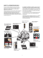 7
7
-
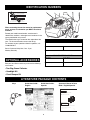 8
8
-
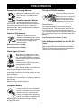 9
9
-
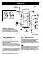 10
10
-
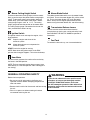 11
11
-
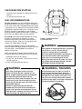 12
12
-
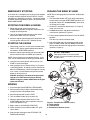 13
13
-
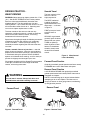 14
14
-
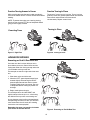 15
15
-
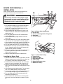 16
16
-
 17
17
-
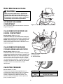 18
18
-
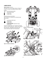 19
19
-
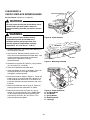 20
20
-
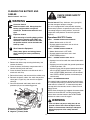 21
21
-
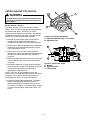 22
22
-
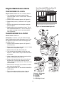 23
23
-
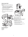 24
24
-
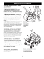 25
25
-
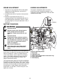 26
26
-
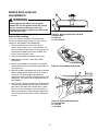 27
27
-
 28
28
-
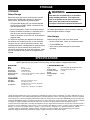 29
29
-
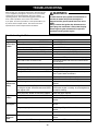 30
30
-
 31
31
-
 32
32
-
 33
33
-
 34
34
-
 35
35
-
 36
36
-
 37
37
-
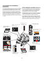 38
38
-
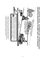 39
39
-
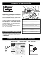 40
40
-
 41
41
-
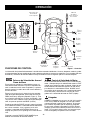 42
42
-
 43
43
-
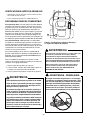 44
44
-
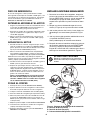 45
45
-
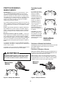 46
46
-
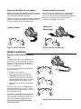 47
47
-
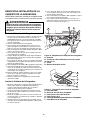 48
48
-
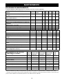 49
49
-
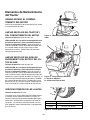 50
50
-
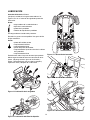 51
51
-
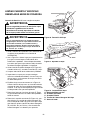 52
52
-
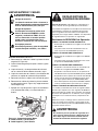 53
53
-
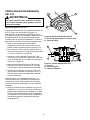 54
54
-
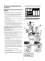 55
55
-
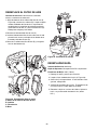 56
56
-
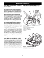 57
57
-
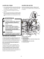 58
58
-
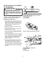 59
59
-
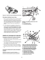 60
60
-
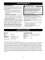 61
61
-
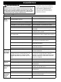 62
62
-
 63
63
-
 64
64
-
 65
65
-
 66
66
-
 67
67
-
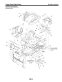 68
68
-
 69
69
-
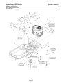 70
70
-
 71
71
-
 72
72
-
 73
73
-
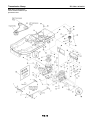 74
74
-
 75
75
-
 76
76
-
 77
77
-
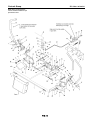 78
78
-
 79
79
-
 80
80
-
 81
81
-
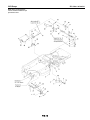 82
82
-
 83
83
-
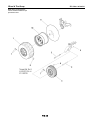 84
84
-
 85
85
-
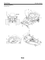 86
86
-
 87
87
-
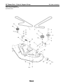 88
88
-
 89
89
-
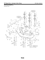 90
90
-
 91
91
-
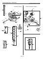 92
92
-
 93
93
-
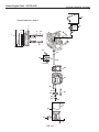 94
94
-
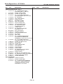 95
95
-
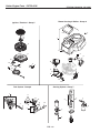 96
96
-
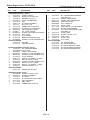 97
97
-
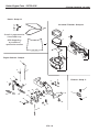 98
98
-
 99
99
-
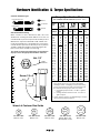 100
100
-
 101
101
-
 102
102


Simplicity SEARS ZTS 7500 RIDER, 26 HP KOHLER W/50" MOWER Manual de usuario
- Categoría
- Cortadoras de césped
- Tipo
- Manual de usuario
- Este manual también es adecuado para
en otros idiomas
Artículos relacionados
-
Simplicity 2691079 Manual de usuario
-
-
-
Simplicity 2691519 Manual de usuario
-
-
Simplicity 2691817 Manual de usuario
-
Briggs & Stratton 2691098-00 Manual de usuario
-
-
-
Otros documentos
-
Craftsman ZTS 7500 Manual de usuario
-
-
-
-
-
-
-
-
White Outdoor 107277700 Manual de usuario
-
Craftsman 107277720 El manual del propietario