CARLO GAVAZZI SIU-MBM-02 Guía de instalación
- Tipo
- Guía de instalación

SIU-MBM-02
Gateway from wM-Bus to Modbus TCP/IP
Instrucon manual
SIU-MBM-02 transforms data from the M-Bus and wireless M-Bus protocol into the Modbus
TCP/IP protocol making them available to a master. It simultaneously integrates up to 20 wired
M-Bus devices and up to 32 wireless M-Bus devices. The UCS soware, available for free
download, scans and idenes connected M-Bus devices and wireless M-Bus devices operang
within the range and automacally creates the Modbus map. This can be exported to a driver to
automacally integrate data in the VMU-C EM master.
Gateway da wM-Bus a Modbus TCP/IP
Manuale d’istruzioni
SIU-MBM-02 trasforma da da protocollo M-Bus e wireless M-Bus in protocollo Modbus TCP/IP
rendendoli disponibili a un supervisore. Integra contemporaneamente no a 20 disposivi M-Bus
cabla e no a 32 disposivi wireless M-Bus. Con il soware UCS, scaricabile gratuitamente,
si individuano tramite scansione i disposivi M-Bus collega e i disposivi wireless M-Bus in
funzione nel raggio d’azione e si crea la mappa Modbus. Questa può essere esportata in un
driver per integrare automacamente i da nel supervisore VMU-C EM.
Gateway von wM-Bus zu Modbus TCP/IP
Bedienungsanleitung
SIU-MBM-02 wandelt Daten aus M-Bus- und aus Wireless M-Bus in das Modbus-Protokoll
TCP/IP um und macht sie für einen Supervisor verfügbar. Er integriert gleichzeig bis zu 20
verkabelte M-Bus-Geräte und bis zu 32 Wireless M-Bus-Geräte. Mit der Soware UCS, die
kostenlos heruntergeladen werden kann, werden durch Abfrage die angeschlossenen M-Bus-
Geräte und die Wireless M-Bus-Geräte in Abhängigkeit von der Reichweite festgestellt und eine
Modbus- Map angelegt. Diese kann wiederum in einen Driver exporert werden, um die Daten
automasch in den Supervisor VMU-C EM zu integrieren.
Passerelle de wM-Bus à Modbus TCP/IP
Manuel d’emploi
SIU-MBM-02 transforme des données du protocole M-Bus et wireless M-Bus en protocole
Modbus TCP/IP en les rendant disponibles à un superviseur. Elle intègre simultanément jusqu’à
20 disposifs M-Bus câblés et jusqu’à 32 disposifs wireless M-Bus. Avec le logiciel UCS,
téléchargeable gratuitement, on idene par balayage les disposifs M-Bus connectés et les
disposifs M-Bus en service dans le rayon d’acon et on crée la mappe Modbus. Celle-ci peut
être exportée dans un pilote pour intégrer automaquement les données dans le superviseur
VMU-C EM.
Puerta de enlace de wM-Bus a Modbus TCP/IP
Manual de instrucciones
SIU-MBM-02 trasforma datos de protocolo M-Bus y M-Bus inalámbrico a protocolo Modbus TCP/
IP poniéndolos a disposición de un supervisor. Integra simultáneamente hasta 20 disposivos
M-Bus cableados y hasta 32 disposivos M-Bus inalámbricos. Con el soware UCS, que puede
descargarse gratuitamente, se detectan mediante barrido los disposivos M-Bus conectados y los
disposivos M-Bus inalámbricos en función del radio de acción y se crea un mapa Modbus. Este
puede exportarse a un controlador para integrar automácamente los datos en el supervisor
VMU-C EM.
Gateway fra wM-Bus l Modbus TCP/IP
Installaonsvejledning
SIU-MBM-02 omdanner data fra protokollen M-Bus og trådløs M-Bus l protokollen Modbus
TCP/IP, så de kan gøres lgængelige for en supervisor.. Samdig integreres indl 20 kablede
M-Bus enheder og indl 32 trådløse M-Bus enheder. Med UCS-soware, som kan downloades
gras, idenceres de M-Bus lsluede enheder og de trådløse M-Bus enheder via scanning i
egenskab af akonsradiussen, og et Modbus-kort oprees. Dee kan eksporteres l en driver
ved automask integraon af data i VMU-C EM supervisoren.
CARATTERISTICHE
Caraerische generali
Materiale PVC
Grado di protezione IP20
Isolamento Vedi “Isolamento ingressi e
uscite”
Montaggio A guida DIN o a muro
Caraerische ambientali
Temperatura di
funzionamento
Da -40 a +85 °C
Temperatura di
immagazzinamento
Da -40 a +85 °C
Isolamento ingressi e uscite
Alimentazione e
porta M-Bus
Non isolato
Alimentazione e
porta Ethernet
2000 V rms/0,5 mA/60 s
Porta M-Bus e porta
Ethernet
2000 V rms/0,5 mA/60 s
Alimentazione
Alimentazione Da 15 a 21 V ca, da 18 a
35 V cc
Consumo 4 W
Conneore Morse a vite
LED
LED Descrizione
ON Gateway acceso
wM-Bus Ricezione comunicazione
wireless M-Bus
M-Bus Ricezione comunicazione
M-Bus
Modbus Ricezione comunicazione
Modbus
Porta Ethernet
Protocolli Modbus TCP/IP
Connessioni Massimo 4
Tipo di collegamento Conneore RJ45
Velocità di
trasmissione
Rilevamento automaco
10/100 base-T
Porta M-Bus
Standard EN13757-2:2013
Protocolli M-Bus
Connessioni Massimo 20 disposivi
Daisy chain o connessione
a stella
Tipo di collegamento Morse a vite
Velocità di
trasmissione
Da 300 a 38.400 bps
Comunicazione wireless M-Bus
Standard EN 13757-4
Protocolli Wireless M-Bus
Connessioni Massimo 32 disposivi
Tipo di collegamento Conneore SMA per antenna
868 MHz
Velocità di
trasmissione
868 MHz
Avvertenze generali
PERICOLO!Par soo tensione.
Elerocuzione, ferite gravi o morte.
L’installazione deve essere eseguita
solo da personale specializzato che opera in
sicurezza. Non ulizzare per scopi diversi da
quelli indica nel seguente manuale.
Questo manuale è parte integrante del
prodoo. Deve essere consultato per
tue le situazioni legate all’installazione
e all’uso. Deve essere mantenuto in buone
condizioni e conservato in un luogo pulito e
accessibile agli operatori.
AVVISO: nessuno è autorizzato ad aprire
il disposivo. Solo il personale
dell’assistenza tecnica CARLO GAVAZZI
può farlo.
Assistenza e garanzia
In caso di malfunzionamento, guasto, necessità
di informazioni o per acquistare altri prodo
GAVAZZI contaare la liale CARLO GAVAZZI o il
distributore nel paese di appartenenza.
Per richiedere assistenza, comunicare Q.n. e Sn
riporta sulle echee del prodoo.
L’installazione e l’uso di SIU-MBM-02 diversi
da quanto indicato nelle istruzioni fornite
invalidano la garanzia.
MANUTENZIONE E SMALTIMENTO
Responsabilità di smalmento
Smalre con raccolta dierenziata
tramite le struure di raccolta
indicate dal governo o dagli en
pubblici locali. Il correo
smalmento e il riciclaggio
aiuteranno a prevenire conseguenze
potenzialmente negave per l’ambiente e per
le persone.
Conformità
Il fabbricante, CARLO GAVAZZI Controls SpA,
dichiara che il po di apparecchiatura radio
SIU-MBC è conforme alla direva 2014/53/
UE. Il testo completo della dichiarazione
di conformità UE è disponibile al seguente
indirizzo Internet:
www.productselection.net/Pdf/UK/SIUMBM02_cert.pdf
HO
°C/°F
VMU-C
M-Bus
UCS Desktop
max 20
Modbus TCP/IP
SIU-MBM
max 32
Pulses
Pulses
HO
Gas
Heat
HO
HO
Gas
wM-Bus
wM-Bus
wM-Bus
wM-Bus
wM-Bus
SIU-MBC
SIU-MBC
ENGLISH ITALIANO DEUTSCH FRANÇAIS
ESPAÑOL
DANSK
FEATURES
General features
Material PVC
Protecon degree IP20
Insulaon See “Input and output
insulaon”
Mounng On DIN rail or on wall
Environmental specicaons
Operang
temperature
From -40 to +85 °C
Storage temperature From -40 to +85 °C
Input and output insulaon
Power supply and
M-Bus port
Not insulated
Power supply and
Ethernet port
2000 V rms/0.5 mA/60 s
M-Bus port and
Ethernet port
2000 V rms/0.5 mA/60 s
Power supply
Power supply From 15 to 21 V ac, from 18
to 35 V dc
Consumpon 4 W
Connector Screw terminals
LED
LED Descripon
ON Gateway ON
wM-Bus Recepon of wireless M-Bus
communicaon
M-Bus Recepon of M-Bus
communicaon
Modbus Recepon of Modbus
communicaon
Ethernet port
Protocols Modbus TCP/IP
Connecons Maximum 4
Connecon type RJ45 connector
Transmission speed Automac detecon 10/100
base-T
M-Bus port
Standard EN13757-2:2013
Protocols M-Bus
Connecons Maximum 20 devices
Daisy chain or star connecon
Connecon type Screw terminals
Transmission speed From 300 to 38,400 bps
M-Bus wireless communicaon
Standard EN 13757-4
Protocols Wireless M-Bus
Connecons Maximum 32 devices
Connecon type SMA connector for 868 MHz
antenna
Transmission speed 868 MHz
General warnings
DANGER!Live parts. Electrocuon,
serious injury or death. Only
specialized personnel working in safety
condions should perform installaon. Do not
use for purposes other than those indicated in
the following manual.
This manual is an integral part of the
product. It should be consulted for all
situaons ed to installaon and use. It
must be kept in good condion and in a clean
locaon accessible to all operators.
NOTICE: no one is authorized to open
the device. This operaon is reserved
exclusively for CARLO GAVAZZI technical
service personnel.
Service and warranty
In the event of malfuncon, fault, requests
for informaon or to purchase other GAVAZZI
products, contact the CARLO GAVAZZI branch
or distributor in your country.
For service, communicate the Q.n. and Sn
indicated on the product label.
Installaon and use of SIU-MBM-02 other than
those indicated in the provided instrucons
void the warranty.
MAINTENANCE AND DISPOSAL
Responsibility for disposal
The product must be disposed of at
the relave recycling centers
specied by the government or local
public authories. Correct disposal
and recycling will contribute to the
prevenon of potenally harmful
consequences to the environment and persons.
Conformity
The manufacturer, CARLO GAVAZZI Controls
SpA, states that the SIU-MBC radio equipment
complies with direcve 2014/53/EU. The full
EU declaraon of conformity text is available
on the following website:
www.productselection.net/Pdf/UK/SIUMBM02_cert.pdf
MERKMALE
Allgemeine Merkmale
Material PVC
Schutzart IP20
Isolaon Siehe “Isolierung Ein- und
Ausgänge”
Montage Auf DIN- Schiene oder an
der Wand
Umgebungsmerkmale
Betriebstemperatur -40 bis +85 °C
Lagertemperatur -40 bis +85 °C
Isolierung Ein- und Ausgänge
Stromversorgung und
M-Bus-Port
Nicht isoliert
Stromversorgung und
Ethernet-Port
2000 V rms/0,5 mA/60 s
M-Bus- Port und
Ethernet-Port
2000 V rms/0,5 mA/60 s
Stromversorgung
Stromversorgung 15 bis 21 V ac, 18 bis 35 V dc
Verbrauch 4 W
Stecker Schraubklemmen
LED
LED Beschreibung
ON Gateway eingeschaltet
wM-Bus Empfang Kommunikaon
Wireless M-Bus
M-Bus Empfang Kommunikaon
M-Bus
Modbus Empfang Kommunikaon
Modbus
Ethernet-Schnistelle
Protokolle Modbus TCP/IP
Verbindungen Maximal 4
Verbindung Stecker RJ45
Baudrate Automasche Erfassung
10/100 Basis-T
M-Bus- Port
Standard EN13757-2:2013
Protokolle M-Bus
Verbindungen Maximal 20 Geräte
Daisy chain oder
Sternschaltung
Verbindung Schraubklemmen
Baudrate 300 bis 38.400 bps
Kommunikaon Wireless M-Bus
Standard EN 13757-4
Protokolle Wireless M-Bus
Verbindungen Maximal 32 Geräte
Verbindung Stecker SMA für Antenne
868 MHz
Baudrate 868 MHz
Allgemeine Hinweise
GEFAHR!Unter Spannung stehende
Teile. Stromschlag, schwere
Verletzungen oder Tod Die Installaon
darf ausschließlich von Fachpersonal und
unter Sicherheitsbedingungen vorgenommen
werden. Nicht für andere als die in
nachfolgender Anleitung beschriebenen
Zwecke verwenden.
Diese Anleitung ist wesentlicher
Bestandteil des Produkts. Sie ist bei
allen Fragen zu Installaon und Betrieb
nachzuschlagen. Sie muss in einwandfreiem
Zustand gehalten und an einem sauberen, für
die Bediener zugänglichen Ort auewahrt
werden.
WARNHINWEIS: es ist niemandem
gestaet, den Gerät zu önen. Dies ist
nur dem Kundendienstpersonal der Fa.
CARLO GAVAZZI gestaet.
Kundendienst und Garane
Bei Funkonsstörungen, Ausfall, Anforderung
von Informaonen oder Erwerb von
zusätzlichen GAVAZZI- Produkten bie Kontakt
mit der Filiale CARLO GAVAZZI oder mit dem
Händler im Installaonsland aufnehmen.
Bei Anforderung von Kundendienst bie
Q.n. und Sn angeben. Diese sind auf dem
Kennschild des Produkts angegeben.
Von den Angaben dieser Anleitung
abweichende Installaon und Betrieb des
Geräts SIU-MBM-02 führen zur Ungülgkeit
der Garane.
WARTUNG UND ENTSORGUNG
Verantwortlichkeit für die Entsorgung
Es muss für getrennte
Abfallentsorgung anhand der von der
Regierung oder den öentliche
Lokalbehörden benannten
Sammelstrukturen gesorgt werden.
Die korrekte Entsorgung bzw. das
Recycling tragen dazu bei, potenell
negave Auswirkungen auf die Umwelt und die
Personen zu vermeiden.
Konformität
Der Hersteller, Fa. CARLO GAVAZZI Controls
SpA, erklärt, dass der Funkgerätetyp SIU-MBC
mit der Richtlinie 2014/53/EU konform ist. Der
Volltext der EU- Konformitätserklärung kann
unter folgender Internet-Adresse eingesehen
werden:
www.productselection.net/Pdf/UK/SIUMBM02_cert.pdf
CARACTÉRISTIQUES
Caractérisques générales
Matériel PVC
Indice de protecon IP20
Isolaon Voir “Isolaon entrées et
sores”
Montage À rail DIN ou mural
Caractérisques environnementales
Température de
fonconnement
De -40 à +85 °C
Température de
stockage
De -40 à +85 °C
Isolaon entrées et sores
Alimentaon et port
M-Bus
Non isolé
Alimentaon et port
Ethernet
2000 V rms/0,5 mA/60 s
Port M-Bus et port
Ethernet
2000 V rms/0,5 mA/60 s
Alimentaon
Alimentaon De 15 à 21 V ca, de 18 à
35 V cc
Consommaon 4 W
Connecteur Bornes à vis
LED
LED Descripon
ON Passerelle allumée
wM-Bus Récepon communicaon
wireless M-Bus
M-Bus Récepon communicaon
M-Bus
Modbus Récepon communicaon
Modbus
Port Ethernet
Protocoles Modbus TCP/IP
Connexions Maximum 4
Type de branchement Connecteur RJ45
Vitesse de
transmission
Relevé automaque 10/100
base-T
Port M-Bus
Standard EN13757-2:2013
Protocoles M-Bus
Connexions Maximum 20 disposifs
Connexion en guirlande ou
en étoile
Type de branchement Bornes à vis
Vitesse de
transmission
De 300 à 38 400 bps
Communicaon wireless M-Bus
Standard EN 13757-4
Protocoles Wireless M-Bus
Connexions Maximum 32 disposifs
Type de branchement Connecteur SMA pour antenne
868 MHz
Vitesse de
transmission
868 MHz
Averssements généraux
RISQUE ! pièces sous tension.
Électrocuon, blessures graves ou
mort. L’installaon doit être eectuée
uniquement par un personnel spécialisé qui
opère en toute sécurité. Ne pas uliser pour
des objecfs diérents de ceux indiqués dans
le manuel d’emploi suivant.
Ce manuel fait pare intégrante du
produit. Il doit être consulté pour toutes
les situaons liées à l'installaon et à
l'ulisaon. Il doit être maintenu dans de
bonnes condions et conservé dans un lieu
propre et accessible aux opérateurs.
AVIS : personne n’est autorisé à ouvrir le
disposif. Seul le personnel de
l’assistance technique CARLO GAVAZZI
peut le faire.
SERVICE ET GARANTIE
En cas de dysfonconnement, de panne,
de besoin d'informaons, ou pour acheter
d’autres produits GAVAZZI, contacter la liale
ou le distributeur CARLO GAVAZZI de votre
pays.
Pour faire demande d’assistance, communiquer
les Q.n. et Sn reportés sur les équees du
produit.
Une installaon et une ulisaon de SIU-
MBM-02 autres que celles indiquées dans les
instrucons fournies invalident la garane.
ENTRETIEN ET ÉLIMINATION
Responsabilité en maère d’éliminaon
Éliminer selon le tri sélecf avec les
structures de récupéraon indiquées
par l’État ou par les organismes
publics locaux. Bien éliminer et
recycler aidera à prévenir des
conséquences potenellement
néfastes pour l’environnement et les
personnes.
CARACTERÍSTICAS
Caracteríscas generales
Material PVC
Grado de protección IP20
Aislamiento Véase “Aislamiento entradas
y salidas”
Montaje En carril DIN o en la pared
Especicaciones medioambientales
Temperatura de
funcionamiento
De -40 a +85 °C
Temperatura de
almacenamiento
De -40 a +85 °C
Aislamiento entradas y salidas
Alimentación y
puerto M-Bus
No aislado
Alimentación y
puerto Ethernet
2000 V rms/0,5 mA/60 s
Puerto M-Bus y
puerto Ethernet
2000 V rms/0,5 mA/60 s
Alimentación
Alimentación De 15 a 21 V ca, de 18 a
35 V cc
Consumo 4 W
Conector Bornes con tornillo
LED
LED Descripción
ON Puerta de enlace encendida
wM-Bus Recepción comunicación
M-Bus inalámbrico
M-Bus Recepción comunicación
M-Bus
Modbus Recepción comunicación
Modbus
Puerto Ethernet
Protocolos Modbus TCP/IP
Conexiones Máximo 4
Tipo de conexión Conector RJ45
Velocidad de
transmisión
Detección automáca 10/100
base-T
Puerto M-Bus
Estándar EN13757-2:2013
Protocolos M-Bus
Conexiones Máximo 20 disposivos
Daisy chain o conexión en
estrella
Tipo de conexión Bornes con tornillo
Velocidad de
transmisión
De 300 a 38.400 bps
Comunicación M-Bus inalámbrico
Estándar EN 13757-4
Protocolos M-Bus inalámbrico
Conexiones Máximo 32 disposivos
Tipo de conexión Conector SMA para antena
868 MHz
Velocidad de
transmisión
868 MHz
Advertencias generales
¡PELIGRO!elementos somedos a
tensión. Electrocución, heridas graves o
muerte. La instalación deberá ser
realizada únicamente por personal
especializado que opera en seguridad. No
ulizar para nes diferentes de los indicados
en el siguiente manual.
Este manual forma parte integrante del
producto. Debe consultarse para todas
las situaciones asociadas a la instalación
y al uso. Debe mantenerse en buenas
condiciones y conservarse en un lugar limpio y
accesible a los operadores.
AVISO: nadie está autorizado para abrir
el disposivo. Solo el personal de la
asistencia técnica CARLO GAVAZZI puede
hacerlo.
Asistencia y garana
En caso de fallo de funcionamiento, avería,
necesidad de información o para adquirir otros
productos CARLO GAVAZZI, contactar a la lial
CARLO GAVAZZI o al distribuidor en el país de
pertenencia.
Para solicitar asistencia, comunicar Q.n. y Sn
presentes en las equetas del producto.
La instalación y el uso del SIU-MBM-02
diferentes de lo indicado en las instrucciones
facilitadas y la rerada del módulo MABC
invalidan la garana.
MANTENIMIENTO Y ELIMINACIÓN
Responsabilidad de eliminación
Eliminar mediante recogida selecva
a través de las estructuras de
recogida indicadas por el gobierno o
por los entes públicos locales. La
correcta eliminación y el reciclaje
ayudarán a prevenir consecuencias
potencialmente negavas para el
medioambiente y para las personas.
Conformidad
El fabricante, CARLO GAVAZZI Controls SpA,
declara que el po de aparato de radio
SIU-MBC responde a la direcva 2014/53/
UE. El texto completo de la declaración de
conformidad UE está disponible en el siguiente
dirección de Internet:
www.productselection.net/Pdf/UK/SIUMBM02_cert.pdf
EGENSKABER
Generelle specikaoner
Materiale Pvc
Tæthedsgrad IP20
Isolering Se “Isolering af ind- og
udgange”
Montering Med DIN-skinne eller
vægmontering
Miljømæssige egenskaber
Dristemperatur Fra -40 l +85° C
Oplagringstempe-
ratur
Fra -40 l +85° C
Isolering af ind- og udgange
Strømforsyning og
M-Bus portal
Ikke isoleret
Strømforsyning og
Ethernet port
2000 V rms/0,5 mA/60 sek.
M-Bus port og
Ethernet port
2000 V rms/0,5 mA/60 sek.
Strømforsyning
Strømforsyning Fra 15 l 21 V ac, fra 18 l
35 V dc
Forbrug 4 W
Konnektor Skrueterminaler
LED
LED Beskrivelse
ON Adgang via gateway
wM-Bus Modtagelse af trådløse M-Bus
kommunikaon
M-bus Modtagelse af M-Bus
kommunikaon
Modbus Modtagelse af Modbus-
kommunikaon
Ethernet port
Protokoller Modbus TCP/IP
Tilslutninger Maks. 4
Tilslutningstype RJ45-konnektor
Transmissionsha-
sghed
Automask detektering af
10/100 base-T
M-Bus port
Standard EN13757-2:2013
Protokoller M-bus
Tilslutninger Maks. 20 enheder
Daisy chain eller
stjernelslutning
Tilslutningstype Skrueterminaler
Transmissionsha-
sghed
Fra 300 l 38.400 bps
Trådløs M-Bus kommunikaon
Standard EN 13757-4
Protokoller Trådløs M-bus
Tilslutninger Maks. 32 enheder
Tilslutningstype SMA-konnektor l 868 MHz
antenne
Transmissionsha-
sghed
868 MHz
Generelle advarsler
FARE!Spændingsførende dele. Død ved
elektricitet, alvorlig kvæstelse eller
dødsfald. Installaonen må kun udføres
fagkyndigt personale, som arbejder i
sikkerhed. Må ikke anvendes l andre formål
end de, der er angivet i følgende vejledning.
Denne vejledning er en integreret del af
produktet. Den skal ald konsulteres i
alle situaoner, som drejer sig om
installaon og brug. Den skal opbevares i god
stand på et rent sted, som er let lgængeligt for
operatørerne.
ADVARSEL: Ingen er autoriseret l at
åbne enheden. Kun teknikere fra CARLO
GAVAZZI må gøre dee.
Service og garan
Hvis der opstår fejlfunkoner og defekter, eller
hvis der er brug for oplysninger, eller der skal
købes GAVAZZI-produkter, bedes du kontakte
den lokale CARLO GAVAZZI-forhandler eller
-afdeling.
For at anmode om assistance indsendes Q.n.
og Sn, som er angivet på produktekeen.
Ved installaon og brug af andre SIU-MBM-02
end de, der er angivet i den medfølgende
vejledning, boralder garanen.
HÅNDTERING OG BORTSKAFFELSE
Ansvar vedrørende bortskaelse
Sorteres og bortskaes på
genbrugsplads, som angivet af stat
eller kommune. Den korrekte
bortskaelse og genbrug er med l at
forhindre potenelt negave følger
for miljøet og personer.
Overensstemmelse
Fabrikanten CARLO GAVAZZI Controls SpA
erklærer hermed at typen af radioapparatet
SIU-MBC er i overensstemmelse med direkvet
2014/53/EU. Hele teksten l erklæringen om
EU-overensstemmelse ndes på følgende
website på interneet:
www.productselection.net/Pdf/UK/SIUMBM02_cert.pdf

CARLO GAVAZZI Controls SpA
via Saorze, 8 32100 Belluno (BL) Italy
www.gavazziautomaon.com
info@gavazzi-automaon.com
info: +39 0437 355811 / fax: +39 0437 355880
www.productselecon.net 2018-12 | 8021859 | COPYRIGHT ©2018
ENGLISH
INSTALLAZIONE
Installare SIU-MBM-02
PERICOLO! Par soo tensione.
Elerocuzione, ferite gravi o morte.
Scollegare l’alimentazione prima di
installare il disposivo.
AVVISO: par soo tensione. Danni al
disposivo. Rispeare la polarità
dell’alimentazione indicata nello
schema di collegamento.
Nota: l’installazione in quadri metallici riduce
la ricezione del segnale.
1. Montare a guida DIN.
2. Posizionare l’antenna in vercale.
3. Eseguire i collegamen elerici.
PROCEDURE D’USO CON UCS
Scaricare UCS
Scaricare UCS dal sito www.productselecon.
net/Download/UK/ucs.zip.
Impostare i parametri di rete (solo al
primo ulizzo di UCS)
1. Scollegare l’alimentazione e posizionare il
DIP switch [A] su ON.
2. Collegare l’alimentazione: i LED
lampeggiano velocemente e SIU-MBM-02
assume l’IP di default 192.168.2.205.
3. Collegare punto a punto SIU-MBM-02 al PC
tramite cavo Ethernet.
4. Impostare l’indirizzo IP del PC come staco
nella stessa classe del SIU-MBM-02 (es.:
192.168.2.10).
5. Avviare UCS e nella sezione Gateway
impostare i parametri di rete (indirizzo IP
staco, subnet mask e gateway) assegna
dall’amministratore di rete.
6. Scollegare l’alimentazione e posizionare il
DIP switch [A] su OFF.
7. Collegare l’alimentazione.
Conneere SIU-MBM-02 a UCS
1. Collegare SIU-MBM-02 alla rete LAN
tramite cavo e il PC alla stessa rete LAN.
2. Avviare UCS.
Congurare SIU-MBM-02 e generare la
mappa Modbus
1. Creare una congurazione con nome
signicavo per visualizzarla in seguito.
2. Avviare una o più scansioni aendendo i
tempi di ricezione e selezionare le variabili
da inserire nella mappa Modbus.
3. Se necessario, modicare i parametri dei
disposivi e delle variabili e salvare: UCS
invia la congurazione a SIU-MBM-02 e
crea il driver XML da scaricare e importare
nel VMU-C EM.
Suggerimento: per una più facile
idencazione nella mappa, aribuire un
nome signicavo a ciascun disposivo/
variabile.
UCS desktop (Windows 7 or later)
www.productselecon.net/Download/UK/ucs.zip
ENGLISH
DIAGNOSTICA E RISOLUZIONE
PROBLEMI
Variabili di diagnosca
Variabile Descrizione Intervallo valori
possibili
Status Indicatore di
ricezione frame
0: ricezione
avvenuta
Nota: per disposivi
wireless è 0 se
è stato ricevuto
almeno un frame.
FF (255): ricezione
non avvenuta
Access
number
Numero
idencavo
dei frame dei
disposivi
wireless
Da 0 a FF (255)
per poi riparre
da 0 (incrementa a
ogni nuovo frame
ricevuto)
Potenza del
segnale
Indicatore della
potenza del
segnale wireless
Da 0 a -90 (dove 0
è potenza massima
e -90 è potenza
minima)
Risoluzione problemi comunicazione
Problema Soluzione
Leure Modbus
consecuve presentano
lo stesso access number
per un tempo superiore a
quello di invio dei frame
dei disposivi wireless
impostato
Riposizionare SIU-
MBM-02 o il disposivo
wireless M-Bus
Valore di potenza del
segnale uguale o di poco
superiore a -90
Se possibile,
riposizionare SIU-
MBM-02 o il disposivo
wireless M-Bus
IMPORTANTE: le variabili di diagnosca sono inserite automacamente nella mappa.
SIU-MBM-02
-+ MM
M-Bus
device
M-Bus
device
Modbus TCP/IP
Master
+-
15–21 V ac
18–35 V dc
max 20
0.5-3 mm²
0.5 Nm
LAN
95
55
mm
71
20
60
A
ITALIANO DEUTSCH FRANÇAIS ESPAÑOL DANSK
ITALIANO
DEUTSCH
FRANÇAIS
DANSK ESPAÑOL
INSTALLATION
Install SIU-MBM-02
DANGER! Live parts. Electrocuon,
serious injury or death. Disconnect
the power supply before installing the
device.
NOTICE: live parts. Device damages.
Observe the power polarity indicated
in the wiring diagram.
Note: installaon in metal panels reduces
signal recepon.
1. Mount on the DIN rail.
2. Posion the antenna vercally.
3. Complete electrical connecons.
USE PROCEDURES WITH UCS
Download UCS
Download UCS from www.productselecon.
net/Download/UK/ucs.zip.
Set network parameters (only upon
rst UCS use)
1. Disconnect the power supply and turn the
DIP switch [A] ON.
2. Connect the power supply: the LEDs blink
quickly and SIU-MBM-02 takes the default
IP 192.168.2.205.
3. Point-to-point connect SIU-MBM-02 to the
PC via Ethernet cable.
4. Set the PC IP address as stac in the same
class as SIU-MBM-02 (i.e.: 192.168.2.10).
5. Start UCS and set network parameters
(stac IP address, subnet mask and
gateway) assigned by the network
administrator in the Gateway secon.
6. Disconnect the power supply and turn the
DIP switch [A] OFF.
7. Connect the power supply.
Connect SIU-MBM-02 to UCS
1. Connect SIU-MBM-02 to the LAN via cable
and the PC to the same LAN.
2. Start UCS.
Congure SIU-MBM-02 and generate
the Modbus map
1. Create a conguraon with a signicant
name to view it later.
2. Launch one or more scans according to
receiving mes and select the variables to
be entered in the Modbus map.
3. If necessary, edit device parameters
and variables and save: UCS sends the
conguraon to SIU-MBM-02 and creates
the XML driver to be downloaded and
imported in VMU-C EM.
Tip: for easier idencaon in the map,
assign a signicant name to each device/
variable.
DIAGNOSTICS AND TROUBLESHOOTING
Diagnosc variables
Variable Descripon Possible value
range
Status Frame receiving
indicator
0: received
Note: it is 0 for
wireless devices if
at least one frame
has been received.
FF (255): not
received
Access
number
Frame
idencaon
number of
wireless devices
From 0 to FF (255)
and restart from
0 (increased with
each new frame
received)
Signal
power
Wireless signal
power indicator
From 0 to -90
(where 0 is the
maximum power
and -90 is the
minimum)
Communicaon troubleshoong
Problem Soluon
Consecuve Modbus
readings have the same
access number for a me
over the set sending me
for wireless devices frame
Reposion SIU-MBM-02
or M-Bus wireless device
Signal power value equal to
or just above -90
If possible, reposion
SIU-MBM-02 or the
M-Bus wireless device
IMPORTANT: the diagnosc variables are automacally included in the map.
INSTALLATION
Installaon des SIU-MBM-02
GEFAHR! Unter Spannung stehende
Teile. Stromschlag, schwere
Verletzungen oder Tod Vor Installaon
des Geräts die Stromversorgung
unterbrechen.
WARNHINWEIS: unter Spannung
stehende Teile. Geräteschäden. Die im
Anschlussplan angegebene Polung der
Stromversorgung einhalten.
Hinweis: die Installaon in Metall-
Schaltschränken beeinträchgt den Empfang
des Signals.
1. Auf DIN-Schiene moneren.
2. Die Antenne verkal posionieren
3. Die elektrischen Anschlüsse vornehmen.
BETRIEBSABLÄUFE MIT UCS
Herunterladen von UCS
UCS von der Website www.productselecon.
net/Download/UK/ucs.zip. herunterladen.
Netzparameter eingeben (nur bei
erstmaliger Verwendung von UCS)
1. Die Stromversorgung unterbrechen und
den DIP- Schalter [A] auf ON stellen.
2. Die Stromversorgung anlegen: die LEDs
blinken schnell und der SIU-MBM-02
übernimmt den Default IP-Code
192.168.2.205.
3. Punkt-zu- Punkt-Anschluss des SIU-
MBM-02 am PC miels Ethernet-Kabel
vornehmen.
4. Die IP-Adresse des PCs als stasche
Adresse in der gleichen Klasse des SIU-
MBM-02 eingeben (z.B.: 192.168.2.10).
5. UCS starten und der Sekon Gateway die
vom Netz-Administrator zugeordneten
Netzparameter eingeben (stasche IP-
Adresse, Subnet mask und Gateway).
6. Die Stromversorgung unterbrechen und
den DIP- Schalter [A] auf OFF stellen.
7. Die Stromversorgung anschließen.
Verbindung zwischen SIU-MBM-02 und
UCS herstellen
1. SIU-MBM-02 anhand des Kabels am LAN-
Netz anschließen. Den PC am gleichen
LAN- Netz anschließen.
2. UCS starten.
Konguraon von SIU-MBM-02 und
Generieren der Modbus-Map
1. Eine Konguraon mit verständlichem
Namen anlegen, um sie später anzeigen
zu können.
2. Eine oder mehrere Abfragen vornehmen,
Empfangszeit abwarten und die Variablen
selekeren die in die Modbus-Map
aufgenommen werden sollen.
3. Falls notwendig, die Parameter der Geräte
und die Variablen ändern und speichern:
UCS sendet die Konguraon an SIU-
MBM-02 und legt den Driver XML an, der
herunterzuladen und in den VMU-C EM zu
imporeren ist.
Empfehlung: um die Map leichter
idenzieren zu können, sollte jedem
Gerät/Variablen ein verständlicher Name
zuteilt werden.
DIAGNOSTIK UND BESEITIGUNG VON
STÖRUNGEN
Diagnosk-Variable
Variable Beschreibung Möglicher
Wertebereich
Status Frame- Empfang-
smeldung
0: Empfang erfolgt
Hinweis: bei
Wireless-Geräten
ist der Wert 0, wenn
mindestens ein
Frame empfangen
wurde
FF (255): Empfang
nicht erfolgt
Access
number
Kenn-Nummer
der Frames
von drahtlosen
Geräten
Von 0 bis FF (255),
dann wieder ab 0
(wird bei jedem
empfangenen
neuen Frame
erhöht)
Signallei-
stung
Meldung der
Wireless-
Signalleistung
0 bis -90 (wobei
0 für maximale
Leistung, -90 für
minimale Leistung
steht)
Behebung von Störungen der
Kommunikaon
Störung Abhilfe
Aufeinander folgend
ausgelesene Modbus-
Werte haben die gleiche
Access number für die
Dauer einer Zeit, die über
derjenigen liegt, die bei
Wireless-Geräten für
die Sendung der Frames
eingegebenen wurde.
SIU-MBM-02 bzw. das
Wireless-Gerät M-Bus
wieder anbringen
Wert der Signalleistung
gleich oder knapp über -90
Wenn möglich, SIU-
MBM-02 bzw. das
Wireless-Gerät M-Bus
wieder anbringen
WICHTIG: Die Diagnosevariablen sind automasch in die Map übernommen.
INSTALLATION
Installer le SIU-MBM-02
DANGER ! Pièces sous tension.
Électrocuon, blessures graves ou
mort. Déconnecter l’alimentaon
avant d’installer le disposif.
AVIS : pièces sous tension. Dommages
au disposif. Respecter la polarité de
l’alimentaon indiquée sur le schéma
de branchement.
Note : l’installaon dans des tableaux
métalliques réduit la récepon du signal.
1. Monter sur rail DIN.
2. Posionner l’antenne vercalement.
3. Eectuer les connexions électriques.
PROCÉDURES D’UTILISATION AVEC
UCS
Télécharger UCS
Télécharger UCS depuis le site www.
productselecon.net/Download/UK/ucs.zip.
Congurer les paramètres de réseau
(seulement à la première ulisaon
d’UCS)
1. Débrancher l’alimentaon et placer
l’interrupteur DIP [A] sur ON.
2. Brancher l’alimentaon : les DEL clignotent
rapidement et SIU-MBM-02 prend l’IP par
défaut 192.168.2.205.
3. Connecter point à point SIU-MBM-02 à
l’ordinateur via câble Ethernet.
4. Congurer l’adresse IP de l’ordinateur
comme staque dans la même classe que
la SIU-MBM-02 (ex. : 192.168.2.10).
5. Démarrer UCS et dans la secon
Gateway congurer les paramètres de
réseau (adresse IP staque, masque de
sous-réseau et passerelle) aribués par
l’administrateur de réseau.
6. Débrancher l’alimentaon et placer
l’interrupteur DIP [A] sur OFF.
7. Brancher l’alimentaon.
Connecter SIU-MBM-02 à UCS
1. Relier SIU-MBM-02 au réseau LAN via
câble et l’ordinateur au même réseau LAN.
2. Démarrer UCS.
Congurer SIU-MBM-02 et générer la
mappe Modbus
1. Créer une conguraon avec un nom
signicaf pour la visualiser par la suite.
2. Lancer un ou plusieurs balayages en
aendant les délais de récepon et
séleconner les variables à insérer dans la
mappe Modbus.
3. Si nécessaire, modier les paramètres des
disposifs et des variables et sauvegarder :
UCS envoie la conguraon à SIU-MBM-02
et crée le pilote XML à télécharger et
importer dans le VMU-C EM.
Suggeson : pour faciliter l’idencaon
dans la mappe, aribuer un nom
signicaf à chaque disposif/variable.
DIAGNOSTIC ET RÉSOLUTION DES
PROBLÈMES
Variables de diagnosc
Variable Descripon Intervalle valeurs
possibles
Status Indicateur
de récepon
séquence
0 : récepon
eectuée
Note : pour les
disposifs wireless
la valeur est 0 si au
moins une séquence
a été reçue.
FF (255) : récepon
non eectuée
Access
number
Numéro
d'idencaon
de la séquence
des disposifs
wireless
De 0 à FF (255)
pour ensuite
recommencer
depuis 0 (augmente
à chaque nouvelle
séquence reçue)
Puissance
du signal
Indicateur de
la puissance du
signal wireless
De 0 à -90 (où 0
est la puissance
maximale et -90
est la puissance
minimale)
Résoluon des problèmes de
communicaon
Problème Soluon
Des lectures Modbus
consécuves présentent
le même access number
pendant une durée
supérieure à celle
d’envoi de la séquence
des disposifs wireless
congurée
Reposionner SIU-
MBM-02 ou le disposif
wireless M-Bus
Valeur de puissance du
signal égale ou de peu
supérieure à -90
Si possible,
reposionner SIU-
MBM-02 ou le disposif
wireless M-Bus
IMPORTANT : les variables de diagnosc sont insérées automaquement dans la mappe.
INSTALACIÓN
Instalar SIU-MBM-02
¡PELIGRO! Elementos somedos a
tensión. Electrocución, heridas graves
o muerte. Desconectar la
alimentación antes de instalar el disposivo.
AVISO: elementos somedos a tensión.
Daños en el disposivo. Respetar la
polaridad de la alimentación indicada
en el esquema de conexión.
Nota: la instalación en cuadros metálicos
reduce la recepción de la señal.
1. Montar en carril DIN.
2. Posicionar la antena en vercal.
3. Realizar las conexiones eléctricas.
PROCEDIMIENTOS DE USO CON UCS
Descargar UCS
Descargar UCS desde el sio www.
productselecon.net/Download/UK/ucs.zip.
Congurar los parámetros de red (solo
en el primer uso de UCS)
1. Desconectar la alimentación y posicionar el
DIP switch [A] en ON.
2. Conectar la alimentación: los LED
parpadean rápidamente y SIU-
MBM-02 asume la IP predeterminada
192.168.2.205.
3. Conectar punto a punto SIU-MBM-02 al PC
mediante cable Ethernet.
4. Congurar la dirección IP del PC como
estáca en la misma clase del SIU-MBM-02
(ej.: 192.168.2.10).
5. Iniciar UCS y en la sección Puerta de
enlace congurar los parámetros de red
(dirección IP estáca, máscara de subred
y puerta de enlace) asignados por el
administrador de red.
6. Desconectar la alimentación y posicionar el
DIP switch [A] en OFF.
7. Conectar la alimentación.
Conectar SIU-MBM-02 a UCS
1. Conectar SIU-MBM-02 a la red LAN
mediante cable y el P C a la misma red
LAN.
2. Iniciar UCS.
Congurar SIU-MBM-02 y generar el
mapa Modbus
1. Crear una conguración con un
nombre signicavo para visualizarla a
connuación.
2. Realizar uno o varios barridos esperando
los empos de recepción y seleccionar las
variables a introducir en el mapa Modbus.
3. Si es necesario, modicar los parámetros
de los disposivos y de las variables y
guardar: USC envía la conguración a
SIU-MBM-02 y crea el controlador XML a
descargar e importar en el VMU-C EM.
Sugerencia: para facilitar la idencación
en el mapa, atribuir un nombre
signicavo a cada disposivo/variable.
DIAGNÓSTICO Y RESOLUCIÓN DE
PROBLEMAS
Variables de diagnósco
Variable Descripción Intervalo valores
posibles
Estado Indicador de
recepción cuadro
0: recepción
realizada
Nota: para
disposivos
inalámbricos es 0
si se ha recibido al
menos un cuadro.
FF (255): recepción
no realizada
Número de
acceso
Número
idencavo de
los cuadros de
los disposivos
inalámbricos
De 0 a FF (255) para
luego empezar de
0 (incrementa en
cada nuevo cuadro
recibido)
Potencia de
la señal
Indicador de la
potencia de la
señal inalámbrica
De 0 a -90 (donde
0 es la potencia
máxima y -90 es la
potencia mínima)
Resolución de problemas de
comunicación
Problema Solución
Lecturas Modbus
consecuvas presentan
el mismo número de
acceso durante un empo
superior al de envío de los
cuadros de los disposivos
inalámbricos congurado
Reposicionar SIU-
MBM-02 o el disposivo
inalámbrico M-Bus
Valor de potencia de la
señal igual o ligeramente
superior a -90
Si es posible,
reposicionar SIU-
MBM-02 o el disposivo
inalámbrico M-Bus
IMPORTANTE: las variables de diagnosco se introducen automácamente en el mapa.
INSTALLATION
Installer SIU-MBM-02
FARE! Spændingsførende dele. Død
ved elektricitet, alvorlig kvæstelse
eller dødsfald. Aryd
strømforsyningen, inden enheden installeres.
ADVARSEL: Spændingsførende dele..
Beskadigelse af enheden. Overhold
strømforsyningens polaritet, som er
angivet på lslutningsdiagrammet.
Bemærk: Installaon i metalrammer
nedsæer modtagelsen af signaler.
1. Monter med DIN-skinne
2. Anbring antennen i lodret posion.
3. Udfør de elektriske lslutninger.
PROCEDURER FOR BRUG SAMMEN
MED UCS
Download UCS
Download UCS fra websitet www.
productselecon.net/Download/UK/ucs.zip.
Indsl netværksparametrene (kun ved
den første anvendelse af UCS)
1. Aryd strømforsyningen, og sæt DIP-
omskieren [A] på ON.
2. Akvér strømforsyningen: LED'erne blinker
hurgt, og SIU-MBM-02 får ldelt IP-
adressen 192.168.2.205 som standard.
3. Tilslut SIU-MBM-02 punkt for punkt l
PC'en via Ethernet kabel.
4. Indsl PC'ens IP-adresse som stask i
samme klasse som SIU-MBM-02 (f.eks.:
192.168.2.10)
5. Start UCS og i delen Gateway kongureres
netværksparametrene (stask IP-adresse,
subnet mask og gateway), som er blevet
ldelt af netværksadministratoren.
6. Aryd strømforsyningen, og sæt DIP-
omskieren [A] på OFF.
7. Tilslut strømforsyningen.
Tilslut SIU-MBM-02 l UCS
1. Tilslut SIU-MBM-02 l LAN vha. et kabel og
PC'en l samme LAN.
2. Start UCS.
Kongurer SIU-MBM-02, og generer
Modbus-kortet
1. Opret en navngivet konguraon, så den
kan vises eerfølgende.
2. Start en eller ere scanninger, og vent på
modtagelsesderne, og vælg dereer de
variable, der skal indsæes i Modbus-
kortet.
3. Rediger evt. enhederne parametre og
variablene, og gem dem. UCS sender
konguraonen l SIU-MBM-02,
og opreer XML-driveren, der skal
downloades og importeres i VMU-C EM.
Forslag: For at få en leere idenkaon
i kortet kan du ldele et entydigt navn l
hver enkelt enhed/variabel.
FEJLFINDING OG PROBLEMLØSNING
Variable l fejlnding
Variabel Beskrivelse Interval af mulige
værdier
Status Indikator for
stelmodtagelse
0: modtagelse
udført
Bemærk: Trådløse
enheder er 0, hvis
der mindst er
modtaget et stel.
FF (255):
modtagelse ikke
udført
Adgang-
snummer
Id-nummer for
stel af trådløse
enheder
Fra 0 l FF (255)
for ny afgang fra 0
(øges ved hver ny
stel, der modtages)
Signaleekt Eekndikatoren
af det trådløse
signal
Fra 0 l -90 (hvor 0
er maksimal eekt
og -90 er mindste
eekt)
Løsning af kommunikaonsproblemer
Problem Løsning
De på hinanden følgende
aæsningerne på
Modbus viser samme
adgangsnummer i længere
d end det, der sendes l
stellet for de indsllede
trådløse enheder
Nulsl SIU-MBM-02
eller den trådløse M-Bus
enhed
Signalets eektværdi er lig
eller lidt højere end -90
Nulsl evt. SIU-MBM-02
eller den trådløse M-Bus
enhed
VIGTIGT: Diagnosske variabler indsæes automask på kortet.
2011/65/EU (RoHS - Restricon of Hazardous Substances)
2014/53/EU (RED - Radio Equipment Direcve)
EN13757-3:2013
EN13757-4:2013
Transcripción de documentos
ENGLISH SIU-MBM-02 Gateway from wM-Bus to Modbus TCP/IP Instruction manual SIU-MBM-02 transforms data from the M-Bus and wireless M-Bus protocol into the Modbus TCP/IP protocol making them available to a master. It simultaneously integrates up to 20 wired M-Bus devices and up to 32 wireless M-Bus devices. The UCS software, available for free download, scans and identifies connected M-Bus devices and wireless M-Bus devices operating within the range and automatically creates the Modbus map. This can be exported to a driver to automatically integrate data in the VMU-C EM master. Gateway da wM-Bus a Modbus TCP/IP Manuale d’istruzioni SIU-MBM-02 trasforma dati da protocollo M-Bus e wireless M-Bus in protocollo Modbus TCP/IP rendendoli disponibili a un supervisore. Integra contemporaneamente fino a 20 dispositivi M-Bus cablati e fino a 32 dispositivi wireless M-Bus. Con il software UCS, scaricabile gratuitamente, si individuano tramite scansione i dispositivi M-Bus collegati e i dispositivi wireless M-Bus in funzione nel raggio d’azione e si crea la mappa Modbus. Questa può essere esportata in un driver per integrare automaticamente i dati nel supervisore VMU-C EM. Gateway von wM-Bus zu Modbus TCP/IP Bedienungsanleitung SIU-MBM-02 wandelt Daten aus M-Bus- und aus Wireless M-Bus in das Modbus-Protokoll TCP/IP um und macht sie für einen Supervisor verfügbar. Er integriert gleichzeitig bis zu 20 verkabelte M-Bus-Geräte und bis zu 32 Wireless M-Bus-Geräte. Mit der Software UCS, die kostenlos heruntergeladen werden kann, werden durch Abfrage die angeschlossenen M-BusGeräte und die Wireless M-Bus-Geräte in Abhängigkeit von der Reichweite festgestellt und eine Modbus- Map angelegt. Diese kann wiederum in einen Driver exportiert werden, um die Daten automatisch in den Supervisor VMU-C EM zu integrieren. Passerelle de wM-Bus à Modbus TCP/IP Manuel d’emploi SIU-MBM-02 transforme des données du protocole M-Bus et wireless M-Bus en protocole Modbus TCP/IP en les rendant disponibles à un superviseur. Elle intègre simultanément jusqu’à 20 dispositifs M-Bus câblés et jusqu’à 32 dispositifs wireless M-Bus. Avec le logiciel UCS, téléchargeable gratuitement, on identifie par balayage les dispositifs M-Bus connectés et les dispositifs M-Bus en service dans le rayon d’action et on crée la mappe Modbus. Celle-ci peut être exportée dans un pilote pour intégrer automatiquement les données dans le superviseur VMU-C EM. Puerta de enlace de wM-Bus a Modbus TCP/IP Manual de instrucciones SIU-MBM-02 trasforma datos de protocolo M-Bus y M-Bus inalámbrico a protocolo Modbus TCP/ IP poniéndolos a disposición de un supervisor. Integra simultáneamente hasta 20 dispositivos M-Bus cableados y hasta 32 dispositivos M-Bus inalámbricos. Con el software UCS, que puede descargarse gratuitamente, se detectan mediante barrido los dispositivos M-Bus conectados y los dispositivos M-Bus inalámbricos en función del radio de acción y se crea un mapa Modbus. Este puede exportarse a un controlador para integrar automáticamente los datos en el supervisor VMU-C EM. Gateway fra wM-Bus til Modbus TCP/IP Installationsvejledning SIU-MBM-02 omdanner data fra protokollen M-Bus og trådløs M-Bus til protokollen Modbus TCP/IP, så de kan gøres tilgængelige for en supervisor.. Samtidig integreres indtil 20 kablede M-Bus enheder og indtil 32 trådløse M-Bus enheder. Med UCS-software, som kan downloades gratis, identificeres de M-Bus tilsluttede enheder og de trådløse M-Bus enheder via scanning i egenskab af aktionsradiussen, og et Modbus-kort oprettes. Dette kan eksporteres til en driver ved automatisk integration af data i VMU-C EM supervisoren. UCS Desktop VMU-C Modbus TCP/IP M-Bus H O Gas Heat wM-Bus SIU-MBM wM-Bus wM-Bus wM-Bus Material Protection degree Insulation Mounting PVC IP20 See “Input and output insulation” On DIN rail or on wall Environmental specifications Operating From -40 to +85 °C temperature Storage temperature From -40 to +85 °C Input and output insulation Power supply and M-Bus port Power supply and Ethernet port M-Bus port and Ethernet port Not insulated 2000 V rms/0.5 mA/60 s 2000 V rms/0.5 mA/60 s Power supply Power supply Consumption Connector From 15 to 21 V ac, from 18 to 35 V dc 4W Screw terminals LED LED ON wM-Bus M-Bus Modbus Description Gateway ON Reception of wireless M-Bus communication Reception of M-Bus communication Reception of Modbus communication Ethernet port Protocols Connections Connection type Transmission speed Modbus TCP/IP Maximum 4 RJ45 connector Automatic detection 10/100 base-T M-Bus port Standard Protocols Connections Connection type Transmission speed EN13757-2:2013 M-Bus Maximum 20 devices Daisy chain or star connection Screw terminals From 300 to 38,400 bps M-Bus wireless communication Standard Protocols Connections Connection type Transmission speed EN 13757-4 Wireless M-Bus Maximum 32 devices SMA connector for 868 MHz antenna 868 MHz General warnings DANGER!Live parts. Electrocution, serious injury or death. Only specialized personnel working in safety conditions should perform installation. Do not use for purposes other than those indicated in the following manual. This manual is an integral part of the product. It should be consulted for all situations tied to installation and use. It must be kept in good condition and in a clean location accessible to all operators. NOTICE: no one is authorized to open the device. This operation is reserved exclusively for CARLO GAVAZZI technical service personnel. In the event of malfunction, fault, requests for information or to purchase other GAVAZZI products, contact the CARLO GAVAZZI branch or distributor in your country. For service, communicate the Q.n. and Sn indicated on the product label. Installation and use of SIU-MBM-02 other than those indicated in the provided instructions void the warranty. H O °C/°F MAINTENANCE AND DISPOSAL Responsibility for disposal SIU-MBC Pulses SIU-MBC H O H O The product must be disposed of at the relative recycling centers specified by the government or local public authorities. Correct disposal and recycling will contribute to the prevention of potentially harmful consequences to the environment and persons. Conformity wM-Bus max 32 Gas The manufacturer, CARLO GAVAZZI Controls SpA, states that the SIU-MBC radio equipment complies with directive 2014/53/EU. The full EU declaration of conformity text is available on the following website: www.productselection.net/Pdf/UK/SIUMBM02_cert.pdf DEUTSCH CARATTERISTICHE Caratteristiche generali MERKMALE Allgemeine Merkmale Materiale Grado di protezione Isolamento Material Schutzart Isolation Montaggio PVC IP20 Vedi “Isolamento ingressi e uscite” A guida DIN o a muro Montage PVC IP20 Siehe “Isolierung Ein- und Ausgänge” Auf DIN- Schiene oder an der Wand Caratteristiche ambientali Umgebungsmerkmale Temperatura di funzionamento Temperatura di immagazzinamento Da -40 a +85 °C Betriebstemperatur Lagertemperatur Alimentazione e porta M-Bus Alimentazione e porta Ethernet Porta M-Bus e porta Ethernet Non isolato Da -40 a +85 °C Isolamento ingressi e uscite 2000 V rms/0,5 mA/60 s 2000 V rms/0,5 mA/60 s Alimentazione Service and warranty Pulses max 20 FEATURES General features ITALIANO Alimentazione Consumo Connettore Da 15 a 21 V ca, da 18 a 35 V cc 4W Morsetti a vite LED LED ON wM-Bus M-Bus Modbus Porta Ethernet Protocolli Connessioni Tipo di collegamento Velocità di trasmissione Porta M-Bus Descrizione Gateway acceso Ricezione comunicazione wireless M-Bus Ricezione comunicazione M-Bus Ricezione comunicazione Modbus Modbus TCP/IP Massimo 4 Connettore RJ45 Rilevamento automatico 10/100 base-T Standard Protocolli Connessioni EN13757-2:2013 M-Bus Massimo 20 dispositivi Daisy chain o connessione a stella Tipo di collegamento Morsetti a vite Velocità di Da 300 a 38.400 bps trasmissione Comunicazione wireless M-Bus Standard Protocolli Connessioni Tipo di collegamento Velocità di trasmissione EN 13757-4 Wireless M-Bus Massimo 32 dispositivi Connettore SMA per antenna 868 MHz 868 MHz Avvertenze generali PERICOLO!Parti sotto tensione. Elettrocuzione, ferite gravi o morte. L’installazione deve essere eseguita solo da personale specializzato che opera in sicurezza. Non utilizzare per scopi diversi da quelli indicati nel seguente manuale. Questo manuale è parte integrante del prodotto. Deve essere consultato per tutte le situazioni legate all’installazione e all’uso. Deve essere mantenuto in buone condizioni e conservato in un luogo pulito e accessibile agli operatori. AVVISO: nessuno è autorizzato ad aprire il dispositivo. Solo il personale dell’assistenza tecnica CARLO GAVAZZI può farlo. Assistenza e garanzia In caso di malfunzionamento, guasto, necessità di informazioni o per acquistare altri prodotti GAVAZZI contattare la filiale CARLO GAVAZZI o il distributore nel paese di appartenenza. Per richiedere assistenza, comunicare Q.n. e Sn riportati sulle etichette del prodotto. L’installazione e l’uso di SIU-MBM-02 diversi da quanto indicato nelle istruzioni fornite invalidano la garanzia. MANUTENZIONE E SMALTIMENTO Responsabilità di smaltimento Smaltire con raccolta differenziata tramite le strutture di raccolta indicate dal governo o dagli enti pubblici locali. Il corretto smaltimento e il riciclaggio aiuteranno a prevenire conseguenze potenzialmente negative per l’ambiente e per le persone. Conformità Il fabbricante, CARLO GAVAZZI Controls SpA, dichiara che il tipo di apparecchiatura radio SIU-MBC è conforme alla direttiva 2014/53/ UE. Il testo completo della dichiarazione di conformità UE è disponibile al seguente indirizzo Internet: www.productselection.net/Pdf/UK/SIUMBM02_cert.pdf -40 bis +85 °C -40 bis +85 °C Isolierung Ein- und Ausgänge Stromversorgung und Nicht isoliert M-Bus-Port Stromversorgung und 2000 V rms/0,5 mA/60 s Ethernet-Port M-Bus- Port und 2000 V rms/0,5 mA/60 s Ethernet-Port Stromversorgung Stromversorgung Verbrauch Stecker 15 bis 21 V ac, 18 bis 35 V dc 4W Schraubklemmen LED LED ON wM-Bus M-Bus Modbus Beschreibung Gateway eingeschaltet Empfang Kommunikation Wireless M-Bus Empfang Kommunikation M-Bus Empfang Kommunikation Modbus CARACTERÍSTICAS Características generales EGENSKABER Generelle specifikationer Matériel Indice de protection Isolation Material Grado de protección Aislamiento Materiale Tæthedsgrad Isolering Montage Température de fonctionnement Température de stockage Temperatura de funcionamiento Temperatura de almacenamiento De -40 a +85 °C Aislamiento entradas y salidas Alimentation et port Non isolé M-Bus Alimentation et port 2000 V rms/0,5 mA/60 s Ethernet Port M-Bus et port 2000 V rms/0,5 mA/60 s Ethernet Alimentación y puerto M-Bus Alimentación y puerto Ethernet Puerto M-Bus y puerto Ethernet Alimentation Alimentación Alimentation Consommation Connecteur De 15 à 21 V ca, de 18 à 35 V cc 4W Bornes à vis LED LED ON wM-Bus Alimentación Consumo Conector No aislado 2000 V rms/0,5 mA/60 s 2000 V rms/0,5 mA/60 s LED ON wM-Bus M-Bus Descripción Puerta de enlace encendida Recepción comunicación M-Bus inalámbrico Recepción comunicación M-Bus Recepción comunicación Modbus EN13757-2:2013 M-Bus Maximal 20 Geräte Daisy chain oder Sternschaltung Schraubklemmen 300 bis 38.400 bps Port M-Bus Puerto M-Bus Standard Protocoles Connexions EN13757-2:2013 M-Bus Maximum 20 dispositifs Connexion en guirlande ou en étoile Type de branchement Bornes à vis Vitesse de De 300 à 38 400 bps transmission Estándar Protocolos Conexiones Communication wireless M-Bus Comunicación M-Bus inalámbrico Standard Protocoles Connexions Type de branchement Estándar Protocolos Conexiones Tipo de conexión EN 13757-4 Wireless M-Bus Maximal 32 Geräte Stecker SMA für Antenne 868 MHz 868 MHz GEFAHR!Unter Spannung stehende Teile. Stromschlag, schwere Verletzungen oder Tod Die Installation darf ausschließlich von Fachpersonal und unter Sicherheitsbedingungen vorgenommen werden. Nicht für andere als die in nachfolgender Anleitung beschriebenen Zwecke verwenden. Diese Anleitung ist wesentlicher Bestandteil des Produkts. Sie ist bei allen Fragen zu Installation und Betrieb nachzuschlagen. Sie muss in einwandfreiem Zustand gehalten und an einem sauberen, für die Bediener zugänglichen Ort aufbewahrt werden. WARNHINWEIS: es ist niemandem gestattet, den Gerät zu öffnen. Dies ist nur dem Kundendienstpersonal der Fa. CARLO GAVAZZI gestattet. Kundendienst und Garantie Bei Funktionsstörungen, Ausfall, Anforderung von Informationen oder Erwerb von zusätzlichen GAVAZZI- Produkten bitte Kontakt mit der Filiale CARLO GAVAZZI oder mit dem Händler im Installationsland aufnehmen. Bei Anforderung von Kundendienst bitte Q.n. und Sn angeben. Diese sind auf dem Kennschild des Produkts angegeben. Von den Angaben dieser Anleitung abweichende Installation und Betrieb des Geräts SIU-MBM-02 führen zur Ungültigkeit der Garantie. WARTUNG UND ENTSORGUNG Verantwortlichkeit für die Entsorgung Es muss für getrennte Abfallentsorgung anhand der von der Regierung oder den öffentliche Lokalbehörden benannten Sammelstrukturen gesorgt werden. Die korrekte Entsorgung bzw. das Recycling tragen dazu bei, potentiell negative Auswirkungen auf die Umwelt und die Personen zu vermeiden. Der Hersteller, Fa. CARLO GAVAZZI Controls SpA, erklärt, dass der Funkgerätetyp SIU-MBC mit der Richtlinie 2014/53/EU konform ist. Der Volltext der EU- Konformitätserklärung kann unter folgender Internet-Adresse eingesehen werden: www.productselection.net/Pdf/UK/SIUMBM02_cert.pdf Protocoles Connexions Type de branchement Vitesse de transmission Vitesse de transmission Modbus Puerto Ethernet Modbus TCP/IP Maximum 4 Connecteur RJ45 Relevé automatique 10/100 base-T EN 13757-4 Wireless M-Bus Maximum 32 dispositifs Connecteur SMA pour antenne 868 MHz 868 MHz Avertissements généraux RISQUE ! pièces sous tension. Électrocution, blessures graves ou mort. L’installation doit être effectuée uniquement par un personnel spécialisé qui opère en toute sécurité. Ne pas utiliser pour des objectifs différents de ceux indiqués dans le manuel d’emploi suivant. Ce manuel fait partie intégrante du produit. Il doit être consulté pour toutes les situations liées à l'installation et à l'utilisation. Il doit être maintenu dans de bonnes conditions et conservé dans un lieu propre et accessible aux opérateurs. AVIS : personne n’est autorisé à ouvrir le dispositif. Seul le personnel de l’assistance technique CARLO GAVAZZI peut le faire. SERVICE ET GARANTIE En cas de dysfonctionnement, de panne, de besoin d'informations, ou pour acheter d’autres produits GAVAZZI, contacter la filiale ou le distributeur CARLO GAVAZZI de votre pays. Pour faire demande d’assistance, communiquer les Q.n. et Sn reportés sur les étiquettes du produit. Une installation et une utilisation de SIUMBM-02 autres que celles indiquées dans les instructions fournies invalident la garantie. ENTRETIEN ET ÉLIMINATION Responsabilité en matière d’élimination Éliminer selon le tri sélectif avec les structures de récupération indiquées par l’État ou par les organismes publics locaux. Bien éliminer et recycler aidera à prévenir des conséquences potentiellement néfastes pour l’environnement et les personnes. Protocolos Conexiones Tipo de conexión Velocidad de transmisión Tipo de conexión Velocidad de transmisión Velocidad de transmisión Miljømæssige egenskaber Driftstemperatur Oplagringstemperatur Fra -40 til +85° C Fra -40 til +85° C Isolering af ind- og udgange Strømforsyning og M-Bus portal Strømforsyning og Ethernet port M-Bus port og Ethernet port Ikke isoleret 2000 V rms/0,5 mA/60 sek. 2000 V rms/0,5 mA/60 sek. Strømforsyning Forbrug Konnektor Fra 15 til 21 V ac, fra 18 til 35 V dc 4W Skrueterminaler LED LED Description Passerelle allumée Réception communication wireless M-Bus Réception communication M-Bus Réception communication Modbus Montering Pvc IP20 Se “Isolering af ind- og udgange” Med DIN-skinne eller vægmontering Strømforsyning De 15 a 21 V ca, de 18 a 35 V cc 4W Bornes con tornillo Port Ethernet Allgemeine Hinweise Konformität De -40 à +85 °C De -40 a +85 °C Modbus TCP/IP Maximal 4 Stecker RJ45 Automatische Erfassung 10/100 Basis-T Kommunikation Wireless M-Bus Baudrate De -40 à +85 °C Isolation entrées et sorties Modbus Standard Protokolle Verbindungen Verbindung Montaje PVC IP20 Véase “Aislamiento entradas y salidas” En carril DIN o en la pared Especificaciones medioambientales M-Bus Verbindung Baudrate PVC IP20 Voir “Isolation entrées et sorties” À rail DIN ou mural Caractéristiques environnementales Protokolle Verbindungen Verbindung Baudrate Standard Protokolle Verbindungen DANSK CARACTÉRISTIQUES Caractéristiques générales Ethernet-Schnittstelle M-Bus- Port ESPAÑOL FRANÇAIS Modbus TCP/IP Máximo 4 Conector RJ45 Detección automática 10/100 base-T EN13757-2:2013 M-Bus Máximo 20 dispositivos Daisy chain o conexión en estrella Bornes con tornillo De 300 a 38.400 bps EN 13757-4 M-Bus inalámbrico Máximo 32 dispositivos Conector SMA para antena 868 MHz 868 MHz Advertencias generales LED ON wM-Bus Beskrivelse Adgang via gateway Modtagelse af trådløse M-Bus kommunikation Modtagelse af M-Bus kommunikation Modtagelse af Modbuskommunikation M-bus Modbus Ethernet port Protokoller Tilslutninger Tilslutningstype Transmissionshastighed Modbus TCP/IP Maks. 4 RJ45-konnektor Automatisk detektering af 10/100 base-T M-Bus port Standard Protokoller Tilslutninger Tilslutningstype Transmissionshastighed EN13757-2:2013 M-bus Maks. 20 enheder Daisy chain eller stjernetilslutning Skrueterminaler Fra 300 til 38.400 bps Trådløs M-Bus kommunikation Standard Protokoller Tilslutninger Tilslutningstype Transmissionshastighed EN 13757-4 Trådløs M-bus Maks. 32 enheder SMA-konnektor til 868 MHz antenne 868 MHz Generelle advarsler ¡PELIGRO!elementos sometidos a tensión. Electrocución, heridas graves o muerte. La instalación deberá ser realizada únicamente por personal especializado que opera en seguridad. No utilizar para fines diferentes de los indicados en el siguiente manual. Este manual forma parte integrante del producto. Debe consultarse para todas las situaciones asociadas a la instalación y al uso. Debe mantenerse en buenas condiciones y conservarse en un lugar limpio y accesible a los operadores. AVISO: nadie está autorizado para abrir el dispositivo. Solo el personal de la asistencia técnica CARLO GAVAZZI puede hacerlo. FARE!Spændingsførende dele. Død ved elektricitet, alvorlig kvæstelse eller dødsfald. Installationen må kun udføres fagkyndigt personale, som arbejder i sikkerhed. Må ikke anvendes til andre formål end de, der er angivet i følgende vejledning. Denne vejledning er en integreret del af produktet. Den skal altid konsulteres i alle situationer, som drejer sig om installation og brug. Den skal opbevares i god stand på et rent sted, som er let tilgængeligt for operatørerne. ADVARSEL: Ingen er autoriseret til at åbne enheden. Kun teknikere fra CARLO GAVAZZI må gøre dette. En caso de fallo de funcionamiento, avería, necesidad de información o para adquirir otros productos CARLO GAVAZZI, contactar a la filial CARLO GAVAZZI o al distribuidor en el país de pertenencia. Para solicitar asistencia, comunicar Q.n. y Sn presentes en las etiquetas del producto. La instalación y el uso del SIU-MBM-02 diferentes de lo indicado en las instrucciones facilitadas y la retirada del módulo MABC invalidan la garantía. Service og garanti Asistencia y garantía MANTENIMIENTO Y ELIMINACIÓN Responsabilidad de eliminación Eliminar mediante recogida selectiva a través de las estructuras de recogida indicadas por el gobierno o por los entes públicos locales. La correcta eliminación y el reciclaje ayudarán a prevenir consecuencias potencialmente negativas para el medioambiente y para las personas. Conformidad El fabricante, CARLO GAVAZZI Controls SpA, declara que el tipo de aparato de radio SIU-MBC responde a la directiva 2014/53/ UE. El texto completo de la declaración de conformidad UE está disponible en el siguiente dirección de Internet: www.productselection.net/Pdf/UK/SIUMBM02_cert.pdf Hvis der opstår fejlfunktioner og defekter, eller hvis der er brug for oplysninger, eller der skal købes GAVAZZI-produkter, bedes du kontakte den lokale CARLO GAVAZZI-forhandler eller -afdeling. For at anmode om assistance indsendes Q.n. og Sn, som er angivet på produktetiketten. Ved installation og brug af andre SIU-MBM-02 end de, der er angivet i den medfølgende vejledning, bortfalder garantien. HÅNDTERING OG BORTSKAFFELSE Ansvar vedrørende bortskaffelse Sorteres og bortskaffes på genbrugsplads, som angivet af stat eller kommune. Den korrekte bortskaffelse og genbrug er med til at forhindre potentielt negative følger for miljøet og personer. Overensstemmelse Fabrikanten CARLO GAVAZZI Controls SpA erklærer hermed at typen af radioapparatet SIU-MBC er i overensstemmelse med direktivet 2014/53/EU. Hele teksten til erklæringen om EU-overensstemmelse findes på følgende website på internettet: www.productselection.net/Pdf/UK/SIUMBM02_cert.pdf ENGLISH ITALIANO INSTALLATION Install SIU-MBM-02 DANGER! Live parts. Electrocution, serious injury or death. Disconnect the power supply before installing the device. NOTICE: live parts. Device damages. Observe the power polarity indicated in the wiring diagram. Note: installation in metal panels reduces signal reception. 1. Mount on the DIN rail. 2. Position the antenna vertically. 3. Complete electrical connections. USE PROCEDURES WITH UCS Download UCS Download UCS from www.productselection. net/Download/UK/ucs.zip. Set network parameters (only upon first UCS use) 1. Disconnect the power supply and turn the DIP switch [A] ON. 2. Connect the power supply: the LEDs blink quickly and SIU-MBM-02 takes the default IP 192.168.2.205. 3. Point-to-point connect SIU-MBM-02 to the PC via Ethernet cable. 4. Set the PC IP address as static in the same class as SIU-MBM-02 (i.e.: 192.168.2.10). 5. Start UCS and set network parameters (static IP address, subnet mask and gateway) assigned by the network administrator in the Gateway section. 6. Disconnect the power supply and turn the DIP switch [A] OFF. 7. Connect the power supply. Connect SIU-MBM-02 to UCS 1. Connect SIU-MBM-02 to the LAN via cable and the PC to the same LAN. 2. Start UCS. Configure SIU-MBM-02 and generate the Modbus map 1. Create a configuration with a significant name to view it later. 2. Launch one or more scans according to receiving times and select the variables to be entered in the Modbus map. 3. If necessary, edit device parameters and variables and save: UCS sends the configuration to SIU-MBM-02 and creates the XML driver to be downloaded and imported in VMU-C EM. Tip: for easier identification in the map, assign a significant name to each device/ variable. DEUTSCH INSTALLAZIONE Installare SIU-MBM-02 PERICOLO! Parti sotto tensione. Elettrocuzione, ferite gravi o morte. Scollegare l’alimentazione prima di installare il dispositivo. AVVISO: parti sotto tensione. Danni al dispositivo. Rispettare la polarità dell’alimentazione indicata nello schema di collegamento. Nota: l’installazione in quadri metallici riduce la ricezione del segnale. 1. Montare a guida DIN. 2. Posizionare l’antenna in verticale. 3. Eseguire i collegamenti elettrici. PROCEDURE D’USO CON UCS Scaricare UCS Scaricare UCS dal sito www.productselection. net/Download/UK/ucs.zip. Impostare i parametri di rete (solo al primo utilizzo di UCS) 1. Scollegare l’alimentazione e posizionare il DIP switch [A] su ON. 2. Collegare l’alimentazione: i LED lampeggiano velocemente e SIU-MBM-02 assume l’IP di default 192.168.2.205. 3. Collegare punto a punto SIU-MBM-02 al PC tramite cavo Ethernet. 4. Impostare l’indirizzo IP del PC come statico nella stessa classe del SIU-MBM-02 (es.: 192.168.2.10). 5. Avviare UCS e nella sezione Gateway impostare i parametri di rete (indirizzo IP statico, subnet mask e gateway) assegnati dall’amministratore di rete. 6. Scollegare l’alimentazione e posizionare il DIP switch [A] su OFF. 7. Collegare l’alimentazione. Connettere SIU-MBM-02 a UCS 1. Collegare SIU-MBM-02 alla rete LAN tramite cavo e il PC alla stessa rete LAN. 2. Avviare UCS. Configurare SIU-MBM-02 e generare la mappa Modbus 1. Creare una configurazione con nome significativo per visualizzarla in seguito. 2. Avviare una o più scansioni attendendo i tempi di ricezione e selezionare le variabili da inserire nella mappa Modbus. 3. Se necessario, modificare i parametri dei dispositivi e delle variabili e salvare: UCS invia la configurazione a SIU-MBM-02 e crea il driver XML da scaricare e importare nel VMU-C EM. Suggerimento: per una più facile identificazione nella mappa, attribuire un nome significativo a ciascun dispositivo/ variabile. M-Bus device A 0.5 Nm - + INSTALLATION Installation des SIU-MBM-02 GEFAHR! Unter Spannung stehende Teile. Stromschlag, schwere Verletzungen oder Tod Vor Installation des Geräts die Stromversorgung unterbrechen. WARNHINWEIS: unter Spannung stehende Teile. Geräteschäden. Die im Anschlussplan angegebene Polung der Stromversorgung einhalten. Hinweis: die Installation in MetallSchaltschränken beeinträchtigt den Empfang des Signals. 1. Auf DIN-Schiene montieren. 2. Die Antenne vertikal positionieren 3. Die elektrischen Anschlüsse vornehmen. BETRIEBSABLÄUFE MIT UCS Herunterladen von UCS UCS von der Website www.productselection. net/Download/UK/ucs.zip. herunterladen. Netzparameter eingeben (nur bei erstmaliger Verwendung von UCS) 1. Die Stromversorgung unterbrechen und den DIP- Schalter [A] auf ON stellen. 2. Die Stromversorgung anlegen: die LEDs blinken schnell und der SIU-MBM-02 übernimmt den Default IP-Code 192.168.2.205. 3. Punkt-zu- Punkt-Anschluss des SIUMBM-02 am PC mittels Ethernet-Kabel vornehmen. 4. Die IP-Adresse des PCs als statische Adresse in der gleichen Klasse des SIUMBM-02 eingeben (z.B.: 192.168.2.10). 5. UCS starten und der Sektion Gateway die vom Netz-Administrator zugeordneten Netzparameter eingeben (statische IPAdresse, Subnet mask und Gateway). 6. Die Stromversorgung unterbrechen und den DIP- Schalter [A] auf OFF stellen. 7. Die Stromversorgung anschließen. Verbindung zwischen SIU-MBM-02 und UCS herstellen 1. SIU-MBM-02 anhand des Kabels am LANNetz anschließen. Den PC am gleichen LAN- Netz anschließen. 2. UCS starten. Konfiguration von SIU-MBM-02 und Generieren der Modbus-Map 1. Eine Konfiguration mit verständlichem Namen anlegen, um sie später anzeigen zu können. 2. Eine oder mehrere Abfragen vornehmen, Empfangszeit abwarten und die Variablen selektieren die in die Modbus-Map aufgenommen werden sollen. 3. Falls notwendig, die Parameter der Geräte und die Variablen ändern und speichern: UCS sendet die Konfiguration an SIUMBM-02 und legt den Driver XML an, der herunterzuladen und in den VMU-C EM zu importieren ist. Empfehlung: um die Map leichter identifizieren zu können, sollte jedem Gerät/Variablen ein verständlicher Name zuteilt werden. FRANÇAIS ESPAÑOL INSTALLATION Installer le SIU-MBM-02 DANGER ! Pièces sous tension. Électrocution, blessures graves ou mort. Déconnecter l’alimentation avant d’installer le dispositif. AVIS : pièces sous tension. Dommages au dispositif. Respecter la polarité de l’alimentation indiquée sur le schéma de branchement. Note : l’installation dans des tableaux métalliques réduit la réception du signal. 1. Monter sur rail DIN. 2. Positionner l’antenne verticalement. 3. Effectuer les connexions électriques. PROCÉDURES D’UTILISATION AVEC UCS Télécharger UCS Télécharger UCS depuis le site www. productselection.net/Download/UK/ucs.zip. Configurer les paramètres de réseau (seulement à la première utilisation d’UCS) 1. Débrancher l’alimentation et placer l’interrupteur DIP [A] sur ON. 2. Brancher l’alimentation : les DEL clignotent rapidement et SIU-MBM-02 prend l’IP par défaut 192.168.2.205. 3. Connecter point à point SIU-MBM-02 à l’ordinateur via câble Ethernet. 4. Configurer l’adresse IP de l’ordinateur comme statique dans la même classe que la SIU-MBM-02 (ex. : 192.168.2.10). 5. Démarrer UCS et dans la section Gateway configurer les paramètres de réseau (adresse IP statique, masque de sous-réseau et passerelle) attribués par l’administrateur de réseau. 6. Débrancher l’alimentation et placer l’interrupteur DIP [A] sur OFF. 7. Brancher l’alimentation. Connecter SIU-MBM-02 à UCS 1. Relier SIU-MBM-02 au réseau LAN via câble et l’ordinateur au même réseau LAN. 2. Démarrer UCS. Configurer SIU-MBM-02 et générer la mappe Modbus 1. Créer une configuration avec un nom significatif pour la visualiser par la suite. 2. Lancer un ou plusieurs balayages en attendant les délais de réception et sélectionner les variables à insérer dans la mappe Modbus. 3. Si nécessaire, modifier les paramètres des dispositifs et des variables et sauvegarder : UCS envoie la configuration à SIU-MBM-02 et crée le pilote XML à télécharger et importer dans le VMU-C EM. Suggestion : pour faciliter l’identification dans la mappe, attribuer un nom significatif à chaque dispositif/variable. DANSK INSTALACIÓN Instalar SIU-MBM-02 ¡PELIGRO! Elementos sometidos a tensión. Electrocución, heridas graves o muerte. Desconectar la alimentación antes de instalar el dispositivo. AVISO: elementos sometidos a tensión. Daños en el dispositivo. Respetar la polaridad de la alimentación indicada en el esquema de conexión. Nota: la instalación en cuadros metálicos reduce la recepción de la señal. 1. Montar en carril DIN. 2. Posicionar la antena en vertical. 3. Realizar las conexiones eléctricas. PROCEDIMIENTOS DE USO CON UCS Descargar UCS INSTALLATION Installer SIU-MBM-02 FARE! Spændingsførende dele. Død ved elektricitet, alvorlig kvæstelse eller dødsfald. Afbryd strømforsyningen, inden enheden installeres. ADVARSEL: Spændingsførende dele.. Beskadigelse af enheden. Overhold strømforsyningens polaritet, som er angivet på tilslutningsdiagrammet. Bemærk: Installation i metalrammer nedsætter modtagelsen af signaler. 1. Monter med DIN-skinne 2. Anbring antennen i lodret position. 3. Udfør de elektriske tilslutninger. Descargar UCS desde el sitio www. productselection.net/Download/UK/ucs.zip. Download UCS fra websitet www. productselection.net/Download/UK/ucs.zip. Configurar los parámetros de red (solo en el primer uso de UCS) 1. Desconectar la alimentación y posicionar el DIP switch [A] en ON. 2. Conectar la alimentación: los LED parpadean rápidamente y SIUMBM-02 asume la IP predeterminada 192.168.2.205. 3. Conectar punto a punto SIU-MBM-02 al PC mediante cable Ethernet. 4. Configurar la dirección IP del PC como estática en la misma clase del SIU-MBM-02 (ej.: 192.168.2.10). 5. Iniciar UCS y en la sección Puerta de enlace configurar los parámetros de red (dirección IP estática, máscara de subred y puerta de enlace) asignados por el administrador de red. 6. Desconectar la alimentación y posicionar el DIP switch [A] en OFF. 7. Conectar la alimentación. Conectar SIU-MBM-02 a UCS Indstil netværksparametrene (kun ved den første anvendelse af UCS) 1. Afbryd strømforsyningen, og sæt DIPomskifteren [A] på ON. 2. Aktivér strømforsyningen: LED'erne blinker hurtigt, og SIU-MBM-02 får tildelt IPadressen 192.168.2.205 som standard. 3. Tilslut SIU-MBM-02 punkt for punkt til PC'en via Ethernet kabel. 4. Indstil PC'ens IP-adresse som statisk i samme klasse som SIU-MBM-02 (f.eks.: 192.168.2.10) 5. Start UCS og i delen Gateway konfigureres netværksparametrene (statisk IP-adresse, subnet mask og gateway), som er blevet tildelt af netværksadministratoren. 6. Afbryd strømforsyningen, og sæt DIPomskifteren [A] på OFF. 7. Tilslut strømforsyningen. Konfigurer SIU-MBM-02, og generer Modbus-kortet Configurar SIU-MBM-02 y generar el mapa Modbus 1. Opret en navngivet konfiguration, så den kan vises efterfølgende. 2. Start en eller flere scanninger, og vent på modtagelsestiderne, og vælg derefter de variable, der skal indsættes i Modbuskortet. 3. Rediger evt. enhederne parametre og variablene, og gem dem. UCS sender konfigurationen til SIU-MBM-02, og opretter XML-driveren, der skal downloades og importeres i VMU-C EM. Forslag: For at få en lettere identifikation i kortet kan du tildele et entydigt navn til hver enkelt enhed/variabel. 1. Crear una configuración con un nombre significativo para visualizarla a continuación. 2. Realizar uno o varios barridos esperando los tiempos de recepción y seleccionar las variables a introducir en el mapa Modbus. 3. Si es necesario, modificar los parámetros de los dispositivos y de las variables y guardar: USC envía la configuración a SIU-MBM-02 y crea el controlador XML a descargar e importar en el VMU-C EM. Sugerencia: para facilitar la identificación en el mapa, atribuir un nombre significativo a cada dispositivo/variable. 60 20 mm 55 2011/65/EU (RoHS - Restriction of Hazardous Substances) 2014/53/EU (RED - Radio Equipment Directive) EN13757-3:2013 EN13757-4:2013 Modbus TCP/IP Master Signal power Wireless signal power indicator Problem Consecutive Modbus readings have the same access number for a time over the set sending time for wireless devices frame Signal power value equal to or just above -90 Solution Reposition SIU-MBM-02 or M-Bus wireless device If possible, reposition SIU-MBM-02 or the M-Bus wireless device IMPORTANT: the diagnostic variables are automatically included in the map. DIAGNOSTICA E RISOLUZIONE PROBLEMI Variabili di diagnostica Variabile Descrizione Status Indicatore di ricezione frame Access number Numero identificativo dei frame dei dispositivi wireless Potenza del Indicatore della segnale potenza del segnale wireless ITALIANO Risoluzione problemi comunicazione Intervallo valori possibili 0: ricezione avvenuta Nota: per dispositivi wireless è 0 se è stato ricevuto almeno un frame. FF (255): ricezione non avvenuta Da 0 a FF (255) per poi ripartire da 0 (incrementa a ogni nuovo frame ricevuto) Da 0 a -90 (dove 0 è potenza massima e -90 è potenza minima) Problema Letture Modbus consecutive presentano lo stesso access number per un tempo superiore a quello di invio dei frame dei dispositivi wireless impostato Valore di potenza del segnale uguale o di poco superiore a -90 Soluzione Riposizionare SIUMBM-02 o il dispositivo wireless M-Bus Se possibile, riposizionare SIUMBM-02 o il dispositivo wireless M-Bus IMPORTANTE: le variabili di diagnostica sono inserite automaticamente nella mappa. DEUTSCH DIAGNOSTIK UND BESEITIGUNG VON STÖRUNGEN Diagnostik-Variable Variable Status Access number Beschreibung Möglicher Wertebereich Frame- Empfang- 0: Empfang erfolgt smeldung Hinweis: bei Wireless-Geräten ist der Wert 0, wenn mindestens ein Frame empfangen wurde FF (255): Empfang nicht erfolgt Kenn-Nummer Von 0 bis FF (255), der Frames dann wieder ab 0 von drahtlosen (wird bei jedem Geräten empfangenen neuen Frame erhöht) Meldung der 0 bis -90 (wobei Wireless0 für maximale Signalleistung Leistung, -90 für minimale Leistung steht) Behebung von Störungen der Kommunikation Störung Aufeinander folgend ausgelesene ModbusWerte haben die gleiche Access number für die Dauer einer Zeit, die über derjenigen liegt, die bei Wireless-Geräten für die Sendung der Frames eingegebenen wurde. Wert der Signalleistung gleich oder knapp über -90 Abhilfe SIU-MBM-02 bzw. das Wireless-Gerät M-Bus wieder anbringen Wenn möglich, SIUMBM-02 bzw. das Wireless-Gerät M-Bus wieder anbringen WICHTIG: Die Diagnosevariablen sind automatisch in die Map übernommen. Beskrivelse Interval af mulige værdier Status Indikator for 0: modtagelse stelmodtagelse udført Bemærk: Trådløse enheder er 0, hvis der mindst er modtaget et stel. FF (255): modtagelse ikke udført AdgangId-nummer for Fra 0 til FF (255) snummer stel af trådløse for ny afgang fra 0 enheder (øges ved hver ny stel, der modtages) Signaleffekt Effektindikatoren Fra 0 til -90 (hvor 0 af det trådløse er maksimal effekt signal og -90 er mindste effekt) Problem De på hinanden følgende aflæsningerne på Modbus viser samme adgangsnummer i længere tid end det, der sendes til stellet for de indstillede trådløse enheder Signalets effektværdi er lig eller lidt højere end -90 VIGTIGT: Diagnostiske variabler indsættes automatisk på kortet. Variable Description Status Indicateur de réception séquence ESPAÑOL Løsning af kommunikationsproblemer UCS desktop (Windows 7 or later) www.productselection.net/Download/UK/ucs.zip Frame identification number of wireless devices Communication troubleshooting FRANÇAIS Variabel LAN Access number Signalleistung DANSK 71 Frame receiving indicator Possible value range 0: received Note: it is 0 for wireless devices if at least one frame has been received. FF (255): not received From 0 to FF (255) and restart from 0 (increased with each new frame received) From 0 to -90 (where 0 is the maximum power and -90 is the minimum) DIAGNOSTIC ET RÉSOLUTION DES PROBLÈMES Variables de diagnostic FEJLFINDING OG PROBLEMLØSNING Variable til fejlfinding SIU-MBM-02 Status 1. Tilslut SIU-MBM-02 til LAN vha. et kabel og PC'en til samme LAN. 2. Start UCS. 1. Conectar SIU-MBM-02 a la red LAN mediante cable y el P C a la misma red LAN. 2. Iniciar UCS. max 20 MM Description Tilslut SIU-MBM-02 til UCS M-Bus device 95 - + Variable PROCEDURER FOR BRUG SAMMEN MED UCS Download UCS 0.5-3 mm² 15–21 V ac 18–35 V dc ENGLISH DIAGNOSTICS AND TROUBLESHOOTING Diagnostic variables Løsning Nulstil SIU-MBM-02 eller den trådløse M-Bus enhed Nulstil evt. SIU-MBM-02 eller den trådløse M-Bus enhed DIAGNÓSTICO Y RESOLUCIÓN DE PROBLEMAS Variables de diagnóstico Variable Descripción Intervalo valores posibles Estado Indicador de 0: recepción recepción cuadro realizada Nota: para dispositivos inalámbricos es 0 si se ha recibido al menos un cuadro. FF (255): recepción no realizada Número de Número De 0 a FF (255) para acceso identificativo de luego empezar de los cuadros de 0 (incrementa en los dispositivos cada nuevo cuadro inalámbricos recibido) Potencia de Indicador de la De 0 a -90 (donde la señal potencia de la 0 es la potencia señal inalámbrica máxima y -90 es la potencia mínima) Resolución de problemas de comunicación Problema Lecturas Modbus consecutivas presentan el mismo número de acceso durante un tiempo superior al de envío de los cuadros de los dispositivos inalámbricos configurado Valor de potencia de la señal igual o ligeramente superior a -90 Solución Reposicionar SIUMBM-02 o el dispositivo inalámbrico M-Bus Si es posible, reposicionar SIUMBM-02 o el dispositivo inalámbrico M-Bus Access number Numéro d'identification de la séquence des dispositifs wireless Puissance du signal Indicateur de la puissance du signal wireless Résolution des problèmes de communication Intervalle valeurs possibles 0 : réception effectuée Note : pour les dispositifs wireless la valeur est 0 si au moins une séquence a été reçue. FF (255) : réception non effectuée De 0 à FF (255) pour ensuite recommencer depuis 0 (augmente à chaque nouvelle séquence reçue) De 0 à -90 (où 0 est la puissance maximale et -90 est la puissance minimale) Problème Des lectures Modbus consécutives présentent le même access number pendant une durée supérieure à celle d’envoi de la séquence des dispositifs wireless configurée Valeur de puissance du signal égale ou de peu supérieure à -90 Solution Repositionner SIUMBM-02 ou le dispositif wireless M-Bus Si possible, repositionner SIUMBM-02 ou le dispositif wireless M-Bus IMPORTANT : les variables de diagnostic sont insérées automatiquement dans la mappe. CARLO GAVAZZI Controls SpA via Safforze, 8 32100 Belluno (BL) Italy www.gavazziautomation.com [email protected] info: +39 0437 355811 / fax: +39 0437 355880 IMPORTANTE: las variables de diagnostico se introducen automáticamente en el mapa. www.productselection.net 2018-12 | 8021859 | COPYRIGHT ©2018-
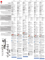 1
1
-
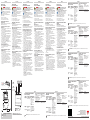 2
2


CARLO GAVAZZI SIU-MBM-02 Guía de instalación
- Tipo
- Guía de instalación
en otros idiomas
Artículos relacionados
-
CARLO GAVAZZI SIU-MBM-01 Guía de instalación
-
-
-
-
-
-
-
-
-