Schumacher DieHard 71496 425W Power Inverter El manual del propietario
- Categoría
- Adaptadores de corriente
- Tipo
- El manual del propietario

0099001101-03
Model / Modelo:
28.71496
OPERATOR’S MANUAL / MANUAL DEL USUARIO
425W Power Inverter
Inversor de energía de 425 vatios
CAUTION:
Read and follow all safety
rules and operating instructions
before every use of this product.
SAVE THESE INSTRUCTIONS.
ATENCIÓN:
Lea y siga todas las reglas
de seguridad e instrucciones de uso
antes de cada uso de este producto.
GUARDE ESTAS INSTRUCCIONES.

DIEHARD
LIMITED WARRANTY
FOR ONE YEAR from the date of sale, this product is warranted against
defects in material or workmanship when it is operated according to all
supplied instructions.
WITH PROOF OF SALE, return a defective product to the retailer from
which it was purchased for free replacement.
This warranty is void if this product is ever used while providing commercial
services or if rented to another person.
This warranty gives you specic legal rights, and you may also have other
rights which vary from state to state.
Schumacher Electric Corporation, Mount Prospect, IL 60056
FOR CUSTOMER ASSISTANCE OR REPLACEMENT PARTS,
CALL 1-800-621-5485 TOLL-FREE
DieHard is a registered trademark of KCD IP, LLC, in the United States, and
Sears Brands, LLC in other countries, used under license.
GARANTÍA LIMITADA DIEHARD
DURANTE UN AÑO desde la fecha de venta, este producto está
garantizado contra defectos de materiales o mano de obra cuando se
opera de acuerdo a las instrucciones provistas.
CON EL COMPROBANTE DE VENTA, devolver un producto defectuoso
a la tienda donde fue comprado para el reemplazo gratuito.
Esta garantía no es válida si el producto se utiliza en cualquier momento
durante la prestación de servicios comerciales o si se alquila a otra persona.
Esta garantía le otorga derechos legales especícos, así como otros
derechos, que varían de estado a estado.
Schumacher Electric Corporation, Mount Prospect, IL 60056
PARA ASISTENCIA AL CLIENTE O REPUESTOS,
LLAME GRATIS AL:
1-800-621-5485
DieHard es una marca registrada de KCD IP, LLC, en los Estados Unidos
de América, y Sears Brands, LLC en otros países, usada bajo licencia.

CONTENTS
IMPORTANT SAFETY INSTRUCTIONS .............................................................. 5
PERSONAL SAFETY PRECAUTIONS .................................................................6
FEATURES ........................................................................................................... 6
BEFORE USING YOUR INVERTER .................................................................... 6
FASTENING THE INVERTER TO A FLAT SURFACE .......................................... 8
CONNECTING INVERTER CABLES ...................................................................9
OPERATING INSTRUCTIONS ............................................................................. 9
POWER SOURCE .............................................................................................. 10
LED INDICATOR AND SHUTDOWN PROTECTION ......................................... 11
HOW POWER INVERTERS WORK ................................................................... 11
IF THE INVERTER’S FUSE BLOWS .................................................................. 12
TROUBLESHOOTING ........................................................................................ 12
SPECIFICATIONS .............................................................................................. 13
REPLACEMENT PARTS .................................................................................... 13
BEFORE RETURNING FOR REPAIRS .............................................................. 13

CONTENIDOS
INSTRUCCIONES IMPORTANTES DE SEGURIDAD ....................................... 14
PRECAUCIONES DE SEGURIDAD PERSONAL .............................................. 15
CARACTERÍSTICAS .......................................................................................... 15
ANTES DE USAR SU INVERSOR ..................................................................... 16
PARA SUJETAR EL CONVERTIDOR A UNA SUPERFICIE PLANA .................. 18
PARA CONECTAR LOS CABLES DEL INVERSOR ........................................... 18
INSTRUCCIONES DE OPERACIÓN .................................................................. 19
FUENTE DE ENERGÍA....................................................................................... 20
INDICADOR LED Y PROTECCIÓN DE DE APAGADO ..................................... 20
CÓMO FUNCIONAN LOS INVERSORES DE CORRIENTE ............................. 21
SI SE QUEMA EL FUSIBLE DEL INVERSOR .................................................... 21
RESOLUCIÓN DE PROBLEMAS ....................................................................... 21
ESPECIFICACIONES ......................................................................................... 22
PIEZAS DE REPUESTO ....................................................................................23
ANTES DE DEVOLVER A REPARACIONES ..................................................... 23

• 5 •
1. IMPORTANT SAFETY INSTRUCTIONS
SAVE THESE INSTRUCTIONS – This manual will show you how to use
your inverter safely and effectively. Please read, understand and follow these
instructions and precautions carefully, as this manual contains important safety
and operating instructions.
WARNING: The inverter’s output is 110V AC and can shock or electrocute, the
same as any ordinary household AC wall outlet.
• Do not cover or obstruct the inverter’s vents.
• Use the inverter in a well-ventilated area.
• This inverter is not intended for use by children.
• Do not expose the inverter to rain or snow.
• Ensure that the inverter is located away from normal trafc areas.
• Use only accessories recommended or sold by the manufacturer.
• Do not operate the inverter with damaged or undersized wiring.
• Do not operate the inverter if it has received a sharp blow, been dropped or
otherwise damaged in any way; take it to a qualied service person.
• Do not disassemble the inverter; take it to a qualied service person when service or
repair is required. Incorrect reassembly may result in a risk of re or electric shock.
• Make sure the inverter is not close to any potential source of ammable fumes,
gases or clothing.
• Do not place the inverter in areas, such as battery compartments or engine
compartments, where fumes or gases may accumulate.
• Disconnect both AC and DC power from the inverter before attempting any cleaning.
• DO NOT operate the inverter if you, the inverter, the device being operated or any
other surfaces that may come into contact with any power source are wet. Water and
many other liquids can conduct electricity, which may lead to serious injury or death.
• Do not place the inverter in direct sunlight. The ideal air temperature for operation
is between 50° and 80°F.
• Only connect the power inverter to a 12 volt accessory outlet or 12 volt battery.
• Do not attempt to connect the inverter to any other power source, including an AC
power source.
• Do not modify the AC receptacles in any way.
• Do not try extending or otherwise changing the 12 volt power cord attached to
your inverter.

• 6 •
• Incorrect operation of your inverter may result in damage and personal injury.
• This device does not include an internal Ground Fault Circuit Interrupter (GFCI).
For GFCI protection, use a Coleman Cable 02822 GFCI outlet.
• Use only 25 amp fuses.
2. PERSONAL SAFETY PRECAUTIONS
• Restrictions on Use:
The inverter may not be used with life support devices or systems. Failure of this
inverter can reasonably be expected to cause failure of that life support device or
system, or to affect the safety or effectiveness of that device or system.
• Wear complete eye and protective clothing when working near lead-acid batteries.
Always have someone nearby for help.
• Remove all personal metal items from your body, such as rings, bracelets,
necklaces and watches. A lead-acid battery can produce a short circuit current
high enough to weld a ring to metal, causing a severe burn.
• Never smoke or allow a spark or ame in the vicinity of the battery or engine.
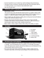
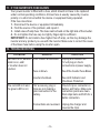
3. FEATURES
2
3
1
4
5
1. AC outlets
2. ON/OFF
rocker switch
3. LED indicators
4. 12 Volt power plug
5. Battery clips
4. BEFORE USING YOUR INVERTER
• This inverter is designed to be used with a single battery, up to group 31 (130 Ah
or smaller). The recommended source of power is a 12 volt deep-cycle battery,
due to their high reserve capacity. Automotive batteries are recommended for only
a short period of time of an hour or less.
• Do not use the inverter with a product that draws a higher wattage than the
converter can provide, as this may cause damage to the inverter and product.

• 7 •
When you turn on a device or a tool that runs on a motor, the device goes through
two stages:
1. Start Up – Requiring an initial surge of power (commonly known as the
“starting” or “peak” load).
2. Continuous Operation – Power consumption drops (commonly known as the
“continuous” load).
The wattage (WATTS) or amperes (AMPS) can normally be found stamped or
printed on most devices and equipment, or in the user’s manual. Otherwise,
contact the manufacturer to nd out whether the device you want to use is
compatible with a modied sine wave.
To calculate the wattage: Wattage = AMPS x 120 (AC Voltage).
To calculate the starting load: Starting Load = 2 x wattage.
In general, the startup load of the device or power tool determines whether your
inverter has the capability to power it.
Always run a test to establish whether the inverter will operate a particular piece of
equipment or device. In the event of a power overload, the inverter is designed to
automatically shut down. This safety feature prevents damaging the inverter while
testing devices and equipment within the wattage range of the inverter.
If a device does not operate properly when rst connected to the inverter, turn the
inverter rocker switch ON (I), OFF (O), and ON (I) again in quick succession. If this
procedure is not successful, it is likely that the inverter does not have the required
capacity to operate the device in question.
This inverter is designed to power 100 watt devices or less when used with the
vehicle 12 volt accessory port. To use the full output, you must use the battery
clips adapter and connect the inverter directly to the battery.
NOTE: The 100 watt limit is to accommodate the fuse ratings for all vehicles.
Some vehicles may allow the full output. If the vehicle fuse blows when you switch
on the device you are trying to use, you have to either use a smaller device or you
must connect the inverter directly to the battery.
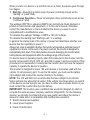
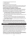
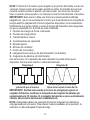
IMPORTANT: This inverter uses a modied sine waveform (diagram A) which is
not quite the same as power company electricity (diagram B). For the following
devices, we strongly recommend that you use caution and check the device’s
manual to make sure it is compatible with modied sine waveform.
1. Switch mode power supplies
2. Linear power supplies
3. Class 2 transformers

• 8 •
4. Line lter capacitors
5. Shaded pole motors
6. Fan motors
7. Microwave ovens
8. Fluorescent and high intensity lamps (with a ballast)
9. Transformer less battery chargers
Using the inverter with any of these devices may cause the device to run warmer
or overheat.
Modied sine waveform
produced by inverter
Diagram A Diagram B
Pure sine waveform
typical of home AC outlet
IMPORTANT: If you are using the power inverter to operate a battery charger,
monitor the temperature of the battery charger for about 10 minutes. If the
battery charger becomes abnormally warm, disconnect it from the inverter
immediately.
NOTE: You can use an extension cord from the inverter to the device without
signicantly decreasing the power being generated by the inverter. For best
operating results, the extension cord should be no longer than 50 feet.
5. FASTENING THE INVERTER TO A FLAT SURFACE
For convenience your inverter can be fastened to a at surface, horizontally or
vertically. The area where the inverter is to be fastened must be dry, well ventilated
and away from any combustible material or fumes.
1. Turn off and disconnect the inverter.
2. Place the back of the inverter with the mounting bracket against a secure and
at surface.
3. Attach the inverter to the at surface using corrosion resistant screws.

• 9 •
6. CONNECTING INVERTER CABLES
The inverter and power source must be in the OFF mode.
IMPORTANT: Make sure you connect your inverter to a 12 volt power supply only.
INVERTER CONNECTION:
NOTE: Determine whether you will be using the battery clips (425 watt output
maximum) or the 12V accessory plug (100 watts maximum).
1. Locate the positive and negative plastic terminals located on the back of the
inverter and remove the terminal caps completely.
2. Install the positive (red) cable ring lug onto the positive (red) terminal screw.
Install the negative (black) cable ring lug onto the negative (black) terminal
screw. Tighten each terminal so that the cable cannot come loose.
CONNECTING INVERTER CABLE TO A VEHICLE (100 WATTS MAXIMUM):
1. Remove the cigarette lighter from its outlet (if applicable).
2. Push the 12 volt power plug rmly into the outlet.
CONNECTING INVERTER CABLES TO 12V BATTERY OR 12V POWER SOURCE:
1. Keep hands, hair, clothing and jewelry clear of battery terminals.
2. Wear eye protection and protective clothing.
3. Connect the positive (red) inverter terminal cable to the power source positive
(+) or battery terminal. Make sure the connection is secure.
4. Connect the negative (black) inverter terminal cable to the power source
negative (-) or battery terminal. Make sure the connection is secure.
5. To disconnect the inverter, reverse the above steps.
NOTE: The internal speaker may make a brief “beep” when the inverter is being
connected to or disconnected from the 12V power source.
CAUTION: Failure to make the correct connections will result in blown fuses and
permanent damage to the inverter.
7. OPERATING INSTRUCTIONS
1. Connect the inverter (see Connecting Inverter Cables section).
2. Switch the inverter switch to the ON (I) position.
3. The LED indicator light should glow GREEN verifying the inverter is receiving
power.
4. Turn the inverter rocker switch to the OFF (O) position. (The GREEN LED
power indicator light may ash briey and/or the internal speaker may make a
brief “beep”. This is normal.).
5. Make sure the device to be operated is turned OFF.

• 10 •
6. Plug the device into the inverter AC outlet.
7. Turn the inverter on.
8. Turn the device on.
9. To disconnect, reverse the above procedure.
NOTE: If more than one device is to be powered, start one device at a time to avoid a
power surge and overloading the inverter. The surge load of each device should not
exceed the inverter’s Continuous Operation wattage rate.
USING THE INVERTER TO OPERATE A TV OR AUDIO DEVICE:
The inverter is shielded and ltered to minimize signal interference. Despite this,
some interference may occur with your television picture, especially with weak
signals. Below are some suggestions to try and improve reception.
1. Try altering the position of the inverter, antenna cables, and television power
cord. Add an extension cord from the inverter to the TV so as to isolate its
power cord and antenna cables from the 12 volt power source.
2. Try coiling the television power cord and the input cables running from the 12V
power source to the inverter.
3. Afx one or several “Ferrite Data Line Filters” to the television power cord.
Ferrite Data Line Filters can be purchased at most electronic supply stores.
4. Try grounding the inverter with an 18 AWG (minimum) (0.75mm2) wire, using
as short a length as possible.
NOTE: You may hear a “buzzing” sound being emitted from inexpensive sound
systems when operated with the inverter. This is due to ineffective lters in the
sound system’s power supply. Unfortunately, this problem can only be resolved by
purchasing a sound system with a higher quality power supply or higher quality lter.
8. POWER SOURCE
Your average automobile or marine battery at full charge will provide an ample power
supply to the inverter for approximately 3 hours when the engine is off. The actual
length of time the inverter will function depends on the age and condition of the battery
and the power demand being placed by the device being operated with the inverter.
Before starting the engine after using the inverter with the engine off, turn OFF the
device plugged into the inverter and disconnect the inverter plug from the 12 volt
accessory outlet. To maintain battery power, start the engine every 2 to 3 hours
and let it run for approximately 30 minutes to recharge the battery.
Although it is not necessary to disconnect the inverter when turning over the engine, it
may briey cease to operate as the battery voltage decreases. While the inverter draws
very low amperage when not in use, unplug it to avoid battery drain.

• 11 •
9. LED INDICATOR AND SHUTDOWN PROTECTION
The LED glows GREEN automatically when plugged into a 12 volt DC source and
will not glow under the following conditions:
1. When the power input from the vehicle’s battery drops to approximately
10±0.5 volts, low battery shutdown occurs and inverter shuts off.
Solution: recharge or replace the battery.
2. When the power input from the vehicle’s battery exceeds 16±0.5 volts, high
voltage overload protection occurs. Solution: Reduce the voltage range to
between 12 volts and 14 volts.
3. The continuous load demand from the equipment or device being operated
exceeds the continuous load rating of the inverter being used.
Solution: Use a higher capacity inverter or lower rated device.
4. The case temperature becomes hot (exceeds 145°F). Solution: Allow the
inverter to cool. Do not block the cooling slots or air ow over and through the
inverter. Reduce the load on the inverter to the continuous rated output.
RESET: To reset after shutdown occurs, switch the inverter On/Off switch to the
OFF position. Check the source of the problem and correct. Switch the inverter
On/Off switch to the ON position.
NOTE: If the red LED is lit and the green LED is not, see Troubleshooting.
10. HOW POWER INVERTERS WORK
There are two stages involved in transforming 12 volt DC (battery) power into 110
volt AC (household voltage):
STAGE 1: The power inverter uses a DC to DC transformer, to increase the
12 volt DC input voltage from the power source to 145 volt DC.
STAGE 2: The inverter then converts the 145 volt DC into 110 volt AC (household
voltage) using advanced MOSFET transistors in a full bridge conguration. A
“modied sine wave” waveform is generated by this conversion.

• 12 •
11. IF THE INVERTER’S FUSE BLOWS
Your power inverter is tted with a fuse, which should not have to be replaced
under normal operating conditions. A blown fuse is usually caused by reverse
polarity or a short circuit within the device or equipment being operated.
If the fuse does blow:
1. Disconnect the device or equipment immediately.
2. Find the source of the problem, and repair it.
3. Install a new 25 amp fuse. The fuses can be found on the right side of the inverter.
4. Do not tighten the fuse cap too tightly; nger-tight is sufcient.
IMPORTANT: Do not install a fuse higher than 25 amp, as this may damage the
inverter and any product you use with the inverter. Make sure to correct the cause
of the blown fuse before using the inverter again.
12. TROUBLESHOOTING
PROBLEM REASON SOLUTION
Red LED is on, audible
alarm is on, and/
or inverter does not
function.
Poor contact at terminals.
Fuse is blown.
Inverter shutdown.
Unplug and reinsert the
12 volt plug or check
connections at power supply.
See If the Inverter Fuse Blows.
See LED Indicator and
Shutdown Protection.
The red LED is lit and
the green LED is not.
12V accessory plug or
clips are not making a
good connection to the
battery.
Connections are reversed.
Check for poor connection to
battery and frame. Make sure
connection points are clean.
Rock clips back and forth for a
better connection.
Unplug the charger and
reverse the clips.

• 13 •
13. SPECIFICATIONS
Maximum continuous power ................................................................. 425 Watts
Surge capability (0.1 second) ............................................................... 850 Watts
No load current draw ...............................................................................0.6A DC
Waveform ............................................................................. Modied Sine Wave
Input voltage ............................................................................... 10.0V-15.0V DC
Output voltage ...............................................................................110V-125V AC
Low battery voltage alarm (buzzer) .............................................10.5V±0.5V DC
Low battery voltage shutdown .....................................................10.0V±0.5V DC
High battery voltage shutdown .....................................................16V ± 0.5V DC
Optimum efciency ........................................................................................85%
AC outlets .......................................................................... Two, NEMA 5-15 USA
Fuse ............................................................................. Two, 25 Amp (blade type)
Dimensions ................................................................ 6.38" L x 4.17" W x 2.24" H
Weight ......................................................................................................1.47 lbs.
14. REPLACEMENT PARTS
Fuses: Replacement fuses can be purchased at most electronic component retailers.
12V accessory plug with cables ......................................................3899003535Z
Battery cable with clips ...................................................................3899003533Z
15. BEFORE RETURNING FOR REPAIRS
When an UNKNOWN OPERATING PROBLEM arises, please read the
complete manual and call the customer service number for information.
This will usually eliminate the need for return.
If the above solutions do not eliminate the problem,
or for information about troubleshooting,
call toll-free from anywhere in the U.S.A.
1-800-621-5485

• 14 •
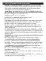
1. INSTRUCCIONES IMPORTANTES DE SEGURIDAD
GUARDE ESTAS INSTRUCCIONES – Este manual le mostrará cómo utilizar
su inversor en forma segura y efectiva. Por favor, lea, comprenda y siga estas
instrucciones y precauciones cuidadosamente, ya que este manual contiene
instrucciones operativas y de seguridad de importancia.
ADVERTENCIA: La salida del inversor es de 110V CA y puede dar una descarga o
electrocutar igual que cualquier toma de corriente de pared doméstica de CA ordinaria.
• No cubra ni obstruya los respiraderos del inversor.
• Utilice el inversor en un área bien ventilada.
• Este inversor no está destinado para ser usado por niños.
• No exponga el inversor a la lluvia o a la nieve.
• Asegúrese de que el convertidor se encuentra lejos de las zonas de tráco normal.
• Utilice solamente los accesorios recomendados o vendidos por el fabricante.
• No utilice el inversor con el cableado dañado o inferior al permitido.
• No utilice el inversor si el mismo recibió un golpe fuerte, si se cayó o si sufrió
daños de cualquier otra forma; hágalo revisar por una persona capacitada que
efectúe reparaciones.
• No desarme el inversor; hágalo revisar por una persona capacitada que efectúe
reparaciones cuando necesite servicio de mantenimiento o una reparación. Volver
a ensamblar el inversor en forma incorrecta puede provocar riesgo de incendio o
descarga eléctrica.
• Asegúrese de que el inversor no esté cerca de ninguna fuente potencial de gases
inamables, gases o ropa.
• No coloque el inversor en áreas tales como compartimientos de baterías o
compartimientos del motor donde los vapores o gases pueden acumularse.
• Desconecte la alimentación CA y CC del inversor antes de intentar limpiarlo.
• NO OPERE el inversor si usted, el inversor, el dispositivo a ser operado o cualquier
otra supercie que puede entrar en contacto con cualquier fuente de energía está
húmeda. El agua y muchos otros líquidos pueden conducir electricidad, lo cual
puede llevar a una lesión seria o la muerte.
• No coloque el inversor en la luz directa del sol. La temperatura del aire ideal para
la operación es entre 50° y 80°F.
• Solamente conecte el inversor de energía a una toma de corriente accesoria de
12V o a una batería de 12V.
• No intente conectar el inversor a cualquier otra fuente de energía, incluyendo una
fuente de energía de CA (corriente alterna).

• 15 •
• No modique las tomas de CA de ninguna manera.
• No trate de extender o cambiar de forma alguna el cable de corriente de 12V
sujeto a su inversor.
• La operación incorrecta de su inversor puede resultar en daño y lesión personal.
• Este dispositivo no incluye un Interruptor de Circuito con conexión a tierra (GFCI
por sus siglas en inglés) interno. Para protección de GFCI, use un Cable Coleman
02822 toma de corriente GFCI.
• Use solamente fusibles de 25 amp.
2. PRECAUCIONES DE SEGURIDAD PERSONAL
• Restricciones de uso:
El inversor no se puede utilizar con dispositivos o sistemas de soporte vital. El
incumplimiento de este inversor puede esperar razonablemente causar fallo de
ese dispositivo de soporte de vida o sistema, o para afectar la seguridad o ecacia
de ese dispositivo o sistema.
• Use protección completo de los ojos y la ropa de protección cuando trabaje cerca
de baterías de plomo-ácido. Siempre cuente con la presencia de otra persona
para obtener ayuda.
• Retire todos los objetos metálicos de su cuerpo (anillos, pulseras, collares y relojes).
Una batería puede producir una corriente de cortocircuito lo sucientemente alta
como para soldar un anillo al metal, lo que ocasionaría una quemadura grave.
• NUNCA fume o permita la presencia de chispas o llamas en la proximidad de una
batería o motor.
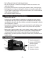
3. CARACTERÍSTICAS
2
3
1
4
5
1. Tomas de corriente de CA
2. Interruptor de ENCENDIDO /
APAGADO (ON/OFF)
3. Indicadores LED
4. Clavija de 12 V energía
5. Abrazaderas de batería

• 16 •
4. ANTES DE USAR SU INVERSOR
• Este inversor ha sido diseñado para ser usado con una sola batería hasta el grupo
31 (130 Ah o menos). La fuente de energía recomendada debe ser de una batería
de ciclo profundo de 12 voltios, debido a sus altas reservas de energía. Las
baterías regulares para automóviles son recomendadas sólo por un corto período
de tiempo de una hora o menos.
• No utilice el inversor con un producto que absorba mayor cantidad de watts que el
inversor pueda proveer, esto podría causar daño al inversor y al producto.
Cuando usted enciende un dispositivo o una herramienta que funciona con un
motor, el dispositivo pasa a través de dos etapas:
1. Arranque – Requiriendo una subida inicial de voltaje (comúnmente conocida
como carga de “inicio” o “pico”).
2. Operación Continua – El consumo de energía desciende (comúnmente
conocido como la “carga continua”).
El vataje (WATTS) o amperaje (AMPS) pueden ser encontrados normalmente
estampados o impresos en la mayoría de los dispositivos y equipo, o en el manual del
usuario. Por lo demás, comuníquese con el fabricante para averiguar si el dispositivo
que usted quiere usar es compatible con una onda senoidal modicada.
Para calcular el vataje: Vataje = AMPS x 120 (Voltaje CA).
Para calcular la carga de arranque: Carga de Arranque = 2 x wattage.
En general, la carga de arranque del dispositivo o herramienta eléctrica determina
si su inversor tiene la capacidad de hacerlo funcionar.
Siempre corra una prueba para establecer si el inversor operará una pieza
particular de equipo o dispositivo. En caso de una sobrecarga de corriente, el
inversor está diseñado para apagarse automáticamente. Ésa característica de
seguridad evitar dañar el inversor mientras se prueban dispositivos y equipo
dentro del ámbito de vataje del inversor.
Si un dispositivo no funciona apropiadamente cuando se conecta por primera vez al
inversor, de vuelta al interruptor broker a ENCENDIDO (ON) (I), APAGADO (OFF)
(O) y nuevamente ENCENDIDO (ON) (I) en rápida sucesión. Si este procedimiento
no tiene éxito, es probable que el inversor no tenga la capacidad requerida para
operar el dispositivo en cuestión.
Este inversor está diseñado para operar aparatos de 100 watts o menos usado el
Puerto de 12 voltios. Para utilizar la salida completa, usted debe usar el adaptador
de las pinzas de la batería y así conectar el inversor directamente a la batería.

• 17 •
NOTA: El límite de 100 watts es para adaptar la proporción del fusible a todos los
vehículos. Algunos vehículos pueden permitir la salida. Si el fusible del vehículo
se funde cuando cambie al aparato que intenta usar, solo tiene dos opciones:
Usar un aparato más pequeño o así conectar el inversor directamente a la batería.
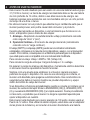
IMPORTANTE: Este inversor utiliza una forma de onda sinusoidal modicada
(diagrama A), que no es exactamente lo mismo que la electricida de la compañía de
energía eléctrica (diagrama B). Para los siguientes dispositivos, le recomendamos
factiblemente que tenga cuidado y revise el manual del dispositivo para asegurarse
de que es compatible con la forma de onda modicada:
1. Fuentes de energía de forma conmutada
2. Fuentes de energía lineal
3. Transformadores clase2
4. Condensadores de capacidad
5. Motores ligeros.
6. Motores de ventilador
7. Hornos de microondas
8. Lámparas ourescentes y de alta intensidad (con balastra)
9. Cargadores de baterías sin tranformador
Uso del inversor con cualquiera de estos dispositivos puede hacer que el
dispositivo funcione más caliente o sobrecalentamiento.
Seno modicada de forma de onda
producido por el inversor
Diagrama A Diagrama B
Sinusoidal pura forma de onda
típico de la casa de la toma de CA
IMPORTANTE: Si usted esta usando el inversor de energía para operar un
cargador de baterías, monitoree la temperatura del cargador de baterías por
aproximadamente 10 minutos. Si el cargador de baterías se pone anormalmente
caliente, desconéctelo del inversor inmediatamente.
NOTA: Usted puede utilizar una extensión del inversor al aparato sin disminuir la
carga generada por el inversor. Para obtener mejores resultados en la operación, la
extension no debe sobrepasar 50 pies de largo.

• 18 •
5. PARA SUJETAR EL CONVERTIDOR A UNA SUPERFICIE PLANA
Por comodidad su convertidor puede ser sujetado a una supercie plana, horizontal o
verticalmente. El área donde el convertidor será sujetado debe ser seca, bien ventilada
y estar alejada de cualquier material o gases combustibles.
1. Apague y desconecte el inversor.
2. Coloque la parte posterior del inversor con el soporte de montaje contra una
supercie segura y plana.
3. Sujete el inversor a la supercie plana usando tornillos resistentes a la corrosión.
6. PARA CONECTAR LOS CABLES DEL INVERSOR
El inversor y la fuente de energía deben estar en el modo APAGADO (OFF).
IMPORTANTE: Asegúrese de conectar su inversor a una fuente de energía de
12 V solamente.
CONEXIÓN DEL INVERSOR:
NOTA: Determine si usara las abrazaderas de la batería (salida máxima de 425
watts) o la clavija accesoria de 12V (máximo 100 watts).
1. Ubique las terminales plásticas positiva y negativa localizadas en el lado
derecho del inversor y quite completamente las tapas de las terminales.
2. Instale el anillo del cable positivo (rojo) en el tornillo de la terminal positiva
(roja). Instale el anillo del cable positivo (negro) en el tornillo de la terminal
positiva (negra). Apriete cada terminal para que el cable no pueda soltarse.
CONEXIÓN DEL INVERSOR AL VEHÍCULO (100 WATTS MÁXIMO):
1. Quite el encendedor de cigarrillos de su toma de corriente (si es aplicable).
2. Empuje la clavija de 12V rmemente en la toma de corriente.
PARA CONECTAR LOS CABLES DEL INVERSOR A UNA BATERÍA
DE 12V O UNA FUENTE DE ENERGÍA DE 12V:
1. Mantenga las manos, cabello, ropa y joyería alejados de las terminales de la batería.
2. Usé protección para ojos y la ropa de protección.
3. Conecte el cable de la terminal positiva (rojo) del inversor a la fuente de energía
positiva (+) o terminal de la batería. Asegúrese de que la conexión sea segura.
4. Conecte el cable de la terminal negativa (negro) del inversor a la fuente de energía
negativa (-) o terminal de la batería. Asegúrese de que la conexión sea segura.
5. Para desconectar el inversor, invierta los pasos anteriores.
NOTA: La bocina interna puede hacer breve “bip” cuando el inversor está siendo
conectado a o desconectado de la fuente de energía de 12V.
ATENCIÓN: El no hacer las conexiones correctas resultará en fusibles quemados
y daño permanente el inversor.

• 19 •
7. INSTRUCCIONES DE OPERACIÓN
1. Conecte el inversor (ver la sección Para Conectar los Cables del Inversor).
2. Cambie el interruptor del inversor a la posición de ENCENDIDO (ON) (I).
3. La luz del indicador LED debe brillar VERDE vericando que el inversor está
recibiendo energía.
4. Cambie el interruptor de balancín del inversor a la posición de APAGADO (OFF)
(O). El indicador de energía LED VERDE puede parpadear brevemente y/o la
bocina interna puede hacer un breve “bip”. Esto es normal.
5. Asegúrese de que el dispositivo a ser operado este APAGADO (OFF).
6. Conecte el dispositivo en la toma de corriente CA del inversor.
7. Encienda el inversor.
8. Enciende el dispositivo.
9. Para desconectar, invierta el procedimiento anterior.
NOTA: Si se va a dar energía a más de un dispositivo, inicie un dispositivo a la vez para
evitar una sobretensión de energía y sobrecargar el inversor. La sobretensión de cada
dispositivo no debe exceder el ámbito de vataje de Operación Continúa el inversor.
PARA USAR EL INVERSOR PARA OPERAR UNA TELEVISIÓN
O DISPOSITIVO DE SONIDO:
El inversor está protegido y ltrado para minimizar la interferencia con la señal. A pesar
de esto, alguna interferencia puede ocurrir con la imagen de su televisión, especialmente
con señales débiles. Abajo y algunas sugerencias para tratar y mejorar la recepción.
1. Trate de alterar la posición del inversor, los cables de la antena y el cable
de corriente de la televisión. Agregue un cable de extensión del inversor a la
televisión para aislar el cable de energía y los cables de la antena de la fuente
de energía de 12V.
2. Intente enrollar el cable de energía de la televisión y los cables de aporte que
van de la fuente de energía de 12V al inversor.
3. Fije uno o varios “Filtros de Línea de Datos de Ferrita” al cable de energía de
la televisión. Los Filtros de Línea de Datos de Ferrita pueden comprarse la
mayor parte de las tiendas de partes electrónicas.
4. Intente conectar a tierra el inversor con un alambre de 18 AWG (medida de cable
americana) (mínimo 0,75mm
2
), usando un tramo tan corto como sea posible.
NOTA: Usted puede escuchar un sonido de “zumbido” siendo emitido de sistemas
de sonido baratos cuando son operados con el inversor. Esto es debido a ltros
inefectivos en el abastecimiento de energía del sistema de sonido. Lamentablemente,
este problema solamente puede ser resuelto comprando un sistema de sonido con
una calidad más alta de abastecimiento de sonido o un ltro de más alta calidad.

• 20 •
8. FUENTE DE ENERGÍA
Su batería de automóvil o marina promedio a toda carga proporcionará un
abastecimiento de energía amplio para él inversor por aproximadamente dos
a tres horas cuando el motor está apagado. El tiempo total que el inversor
funcionará depende de la edad y condición de la batería y de la demanda de
energía colocada por el dispositivo siendo operado con el inversor.
Si decide usar el inversor mientras el motor está apagado, le recomendamos
que apague el dispositivo conectado al inversor antes de arrancar el motor. Para
mantener la energía de la batería, arranque el motor cada dos a tres horas y déjelo
encendido por aproximadamente 30 minutos para recargar la batería.
Aunque no es necesario desconectar el inversor cuando arranca de nuevo el
motor, puede dejar de operar brevemente mientras disminuye el voltaje de la
batería. Aunque el inversor extrae muy poco amperaje cuando no está en uso,
debe ser desconectado para evitar descargar la batería.
9. INDICADOR LED Y PROTECCIÓN DE DE APAGADO
El LED brilla VERDE automáticamente cuando se conecta a una fuente de 12V de
CD y no brillará bajo las siguientes condiciones:
1. Cuando la aportación de energía de la batería del vehículo disminuye
aproximadamente 10±0,5V, o un apagado por batería baja y el inversor se
apaga. Solución: recargue o reemplace la batería.
2. Cuando la aportación de energía de la batería del vehículo excede 16±0,5V, la
protección de sobrecarga de alto voltaje ocurre.
Solución: Reducir el ámbito de voltaje a entre 12V y 14V.
3. La demanda de carga continua del equipo o dispositivo siendo operado excede
la clasicación de carga continua del inversor siendo usado. Solución: Usar un
convertidor de mayor capacidad o un dispositivo de clasicación más baja.
4. La temperatura de la caja se pone caliente (excede los 145 °F).
Solución: Permita que el inversor se enfríe. No bloquee las ranuras de
enfriamiento o el ujo de aire sobre y a través del inversor. Reduzca la carga
sobre el inversor a la salida continua clasicada.
RESTABLECER: Para restablecer después de que ocurre el apagado, cambie
el interruptor On/Off a la posición de OFF. Identique el origen del problema y
corríjalo. Cambie el inversor a la posición ON.
NOTA: Si la luz LED roja está encendida y la luz verde no, consulte la sección de
Localización y Solución de Problemas.

• 21 •
10. CÓMO FUNCIONAN LOS INVERSORES DE CORRIENTE
Hay dos etapas involucradas en la transformación de la energía de 12V de CD
(batería) a 110V de CA (voltaje doméstico):
ETAPA 1: El inversor de corriente usa un transformador de CD a CD para aumentar
la aportación de voltaje de 12V de CD de la fuente de energía a 145V de CD.
ETAPA 2: El inversor entonces convierte los 145V de CD a 110V de CA (voltaje
doméstico) usando avanzados transistores MOSFET en una conguración de
puente completo. Una “onda senoidal modicada” se genera por esta conversión.
11. SI SE QUEMA EL FUSIBLE DEL INVERSOR
Su inversor de corriente está equipado con un fusible, que no tendría que ser
reemplazado bajo condiciones normales de operación. Un fusible quemado es
causado usualmente por una polaridad inversa como un cortocircuito dentro del
dispositivo o equipo siendo operados.
Si el fusible se quema:
1. Desconecte el dispositivo o equipo inmediatamente.
2. Encuentra la fuente del problema, y repárela.
3. Instale un nuevo fusible de 25 amp. Los fusibles puede ser encontrado en el
lado derecho del inversor.
4. No apriete la tapadera del fusible demasiado justa; el ajuste manual es suciente.
IMPORTANTE: No intente instalar un fusible de más de 25 amps, ya que esto
podría dañar el inversor y cualquier producto que use con el inversor. Asegúrese de
corregir la causa del fusible quemado antes de usar el convertidor de nuevo.
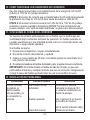
12. RESOLUCIÓN DE PROBLEMAS
PROBLEMA CAUSA POSIBLE SOLUCIÓN
La LED roja está
encendida, la
alarma audible
está encendida, y/o
el convertidor no
funciona.
Mal contacto en las
terminales.
Fusible quemado.
Cierre del inversor.
Desconecte y vuelva a
reinsertar la clavija de 12V
o revise las conexiones a la
fuente de energía.
Ver la sección Si se Quema
el Fusible del Inversor.
Ver la sección Indicador LED y
Protección de Cierre.

• 22 •
PROBLEMA CAUSA POSIBLE SOLUCIÓN
La luz LED roja está
encendida y la luz
verde no.
La clavija accesoria
de 12V o los ganchos
no se encuentran bien
conectados a la batería.
Las conexiones se
encuentran invertidas.
Verique la posible presencia
de una conexión defectuosa
a la batería o al bastidor.
Asegúrese de que los puntos
de conexión estén limpios.
Mueva los ganchos hacia
adelante y hacia atrás para
lograr una mejor conexión.
Desenchufe el cargador e
invierta los ganchos.
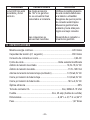
13. ESPECIFICACIONES
Máxima energía continua .................................................................... 425 Vatios
Capacidad de tensión (0,1 segundo) .................................................. 850 Vatios
Consumo de corriente en vacío ............................................................... 0,6A CC
Forma de onda ............................................................Onda senoidal modicada
Ámbito de tensión de entrada .................................................. 10,0V-15,0V CC
Ámbito de tensión de salida ...........................................................110V-125V CA
Alarma de tensión de batería baja (zumbador) ...........................10,5V±0,5V CC
Cierre por tensión de batería baja ...............................................10,0V±0,5V CC
Cierre por tensión de batería alta .................................................16V ± 0,5V CC
Óptima eciencia ...........................................................................................85%
Toma de corriente CA .................................................... Dos, NEMA 5-15 USA
Fusible .............................................................. Dos, 25 amp (fusible de cuchilla)
Dimensiones ................................................................6,38" L x 4,17" A x 2,24" P
Peso ......................................................................................................1,47 libras

• 23 •
14. PIEZAS DE REPUESTO
Fusibles: Fusibles de repuesto se pueden comprar en la mayoría de las tiendas
de componentes electrónicos.
Clavija accesoria de 12V con cables...............................................3899003535Z
Cable de batería con abrazaderas..................................................3899003533Z
15. ANTES DE DEVOLVER A REPARACIONES
Cuando surja un PROBLEMA DE FUNCIONAMIENTO DESCONOCIDO, por
favor lea todo el manual y comuníquese con el número de atención al cliente
para más información que no haga falta la devolución.
Si estas soluciones no eliminan el problema
o si desea obtener más información
sobre la solución de problemas,
llame gratis al desde cualquier parte del U.S.A.
1-800-621-5485
-
 1
1
-
 2
2
-
 3
3
-
 4
4
-
 5
5
-
 6
6
-
 7
7
-
 8
8
-
 9
9
-
 10
10
-
 11
11
-
 12
12
-
 13
13
-
 14
14
-
 15
15
-
 16
16
-
 17
17
-
 18
18
-
 19
19
-
 20
20
-
 21
21
-
 22
22
-
 23
23


Schumacher DieHard 71496 425W Power Inverter El manual del propietario
- Categoría
- Adaptadores de corriente
- Tipo
- El manual del propietario
en otros idiomas
Artículos relacionados
-
Schumacher DieHard 71522 140W Power Inverter El manual del propietario
-
Schumacher Electric PID-760 Power Inverter El manual del propietario
-
Schumacher Electric PI-750 El manual del propietario
-
-
-
-
-
-
-
Otros documentos
-
-
DieHard 28.71495 Manual de usuario
-
-
-
none 4944F2BXS Guía de instalación
-
Kensington 150 Manual de usuario
-
Coleman 3000 WATT Power Inverter Manual de usuario
-
-