DieHard 71496 El manual del propietario
- Categoría
- Adaptadores de corriente
- Tipo
- El manual del propietario

00-99-001101/00
Read all Safety Rules and Operating Instructions,
and follow them with each use of this product.
Lea todas las Instrucciones de Operación y Reglas de Seguridad,
así mismo aplíquelas a cada uso del producto.
ATENCIÓN
Sears Brands Management Corporation, Hoffman Estates, IL 60179 U.S.A.
OWNER’S MANUAL • MANUAL DEL USUARIO
425 Watt Power Inverter
425 Watt Convertidor de Energía
Model / Modelo
71496


TABLE OF CONTENTS
SECTION PAGE
IMPORTANT SAFETY INSTRUCTIONS 1
FEATURES 2
BEFORE USING YOUR POWER INVERTER 2
FASTENING THE INVERTER TO A FLAT SURFACE 4
CONNECTING INVERTER CABLES 4
OPERATING INSTRUCTIONS 5
POWER SOURCE 6
LED INDICATOR AND SHUTDOWN PROTECTION 7
IF THE INVERTER FUSE BLOWS 7
TROUBLESHOOTING 8
SPECIFICATIONS 8
REPLACEMENT PARTS 9
DIEHARD ONE-YEAR FULL WARRANTY
When operated and maintained according to all supplied instructions, if this DieHard
product fails due to a defect in material or workmanship within 1 year from the date of
purchase, return it to any DieHard outlet in the United States for free replacement.
This warranty gives you specic legal rights, and you may also have other rights which
vary from state to state.
Sears Brands Management Corporation, Hoffman Estates, IL 60179
FOR CUSTOMER ASSISTANCE OR REPLACEMENT PARTS,
CALL TOLL-FREE FROM 7 AM TO 5 PM CT
MONDAY THROUGH FRIDAY: 1-800-732-7764

ÍNDICE
SECCIÓN PÀGINA
INSTRUCCIONES IMPORTANTES DE SEGURIDAD 10
CARACTERÍSTICAS DEL CONVERTIDOR 11
ANTES DE USAR SU CONVERTIDOR DE ENERGÍA 12
PARA SUJETAR EL CONVERTIDOR A UNA SUPERFICIE PLANA 13
PARA CONECTAR LOS CABLES DEL CONVERTIDOR 13
INSTRUCCIONES DE OPERACIÓN 15
FUENTE DE ENERGÍA 16
INDICADOR LED Y PROTECCIÓN DE DE APAGADO 16
SI SE QUEMA EL FUSIBLE DEL CONVERTIDOR 17
RESOLUCIÓN DE PROBLEMAS 17
ESPECIFICACIONES 18
PIEZAS DE REPUESTO 18
UN AÑO DE GARANTÍA TOTAL EN DIEHARD
Cuando se opere o maneje con las debidas precauciones de acuerdo a las instrucciones, si el
DieHard falla en alguno de sus componentes de fabricación durante el 1 año contados a partir de
la fecha de compra, regresarlo al autoservicio diehard en los estados unidos para reemplazar el
aparato sin costo alguno.
Esta garantía le otorga derechos legales especícos, así como otros derechos que varían de estado
a estado.
Sears Brands Management Corporation, Hoffman Estates, IL 60179
ASISTENCIA AL CLIENTE O REPOSICIÓN DE PARTES,
SERVICIO DE 7 AM A 5 PM, HORA CENTRO
DE LUNES A VIERNES: 1-800-732-7764

• 1 •
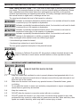
IMPORTANT: READ AND SAVE THIS SAFETY AND INSTRUCTION MANUAL.
SAVE THESE INSTRUCTIONS – The 71496 offers a wide range of features to accommodate
your needs. This manual will show you how to use your inverter safely and effectively. Please
read, understand and follow these instructions and precautions carefully, as this manual
contains important safety and operating instructions. The safety messages used throughout
this manual contain a signal word, a message and an icon.
The signal word indicates the level of the hazard in a situation.
Indicates an imminently hazardous situation which, if not avoided, will result in death
or serious injury to the operator or bystanders.
Indicates a potentially hazardous situation which, if not avoided, could result in death
or serious injury to the operator or bystanders.
Indicates a potentially hazardous situation which, if not avoided, could result in
moderate or minor injury to the operator or bystanders.
Indicates a potentially hazardous situation which, if not avoided, could result in
damage to the equipment or vehicle or property damage.
Safety messages in this manual contain two different type styles.
Unnumbered type states the hazard.•
Numbered type states how to avoid the hazard.•
The icon gives a graphical description of the potential hazard.
Pursuant to California Proposition 65, this product contains chemicals known to the
State of California to cause cancer and birth defects or other reproductive harm.
IMPORTANT SAFETY INSTRUCTIONS1.
RISK OF ELECTRIC SHOCK OR FIRE.
Keep the inverter well ventilated in order to properly disperse heat generated while it is in 1.1
use. Make sure there are several inches of clearance around the top and sides and do not
block the slots of the inverter.
Make sure the inverter is not close to any potential source of ammable fumes, gases 1.2
or clothing.
Do not place the inverter in areas such as battery compartments or engine compartments 1.3
where fumes or gases may accumulate.
Keep the inverter dry.1.4
DO NOT allow the inverter to come into contact with rain or moisture.1.5
DO NOT operate the inverter if you, the inverter, the device being operated or any other 1.6
surfaces that may come into contact with any power source are wet. Water and many other
liquids can conduct electricity, which may lead to serious injury or death.

• 2 •
Do not place the inverter on or near heating vents, radiators or other sources of heat or 1.7
ammable materials.
Do not place the inverter in direct sunlight. The ideal air temperature for operation is 1.8
between 50° and 80°F.
Only connect the power inverter to a 12-volt accessory outlet or 12-volt airplane power 1.9
outlet. Do not attempt to connect the inverter to any other power source, including an AC
power source. Connecting to a 6-volt or 16-volt battery will cause damage to the inverter.
Make sure the AC plug is tight.1.10
Do not modify the inverter in any way including cables, plugs, switches or AC receptacles 1.11
as it may result in property damage or personal injury.
Do not try extending or otherwise changing the input cables that come with your inverter.1.12
Incorrect operation of your inverter may result in damage and personal injury. 1.13
The inverter output is 110V AC and can shock or electrocute the same as
any ordinary household AC wall outlet.
Do not use the inverter with a product that draws a higher wattage than the inverter can 1.14
provide, as this may cause damage to the inverter and product.
Do not open – No user serviceable parts inside.1.15
This device does not include an internal Ground Fault Circuit Interrupter (GFCI).1.16
Use only 25-amp fuses.1.17
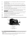
FEATURES2.
ON/OFF Rocker Switch1.
LED Indicators2.
AC Outlets3.
12 Volt Power Plug4.
Battery Clips5.
1
2
3
4
5
BEFORE USING YOUR POWER INVERTER3.
NOTE: This inverter is designed to be used with a single battery, up to group 31 type (130 Ah or
smaller in size).
NOTE: Do not use the inverter with a product that draws a higher wattage than the inverter can
provide, as this may cause damage to the inverter and product.

• 3 •
When you turn on a device or a tool that runs on a motor, the device basically goes through
two stages:
Start Up – Requiring an initial surge of power (commonly known as the “starting or 1.
peak load”).
Continuous Operation – Power consumption drops (commonly known as the 2.
“continuous load”).
The wattage (WATTS) or amperes (AMPS) can normally be found stamped or printed on most
devices and equipment, or in the user’s manual. Otherwise, contact the manufacturer to nd out
whether the device you want to use is compatible with a modied sine wave.
To calculate the wattage: Wattage = AMPS x 120 (AC Voltage).
To calculate the starting load: Starting Load = 2 x WATTS. In general, the start up load of the
device or power tool determines whether your inverter has the capability to power it.
To calculate the continuous load: Continuous Load = AMPS x 120 (AC Voltage).
Always run a test to establish whether the inverter will operate a particular piece of
equipment or device. In the event of a power overload, the inverter is designed to automatically
shut down. This safety feature prevents damaging the inverter while testing devices and equipment
within the wattage range of the inverter.
If a device does not operate properly when rst connected to the inverter, turn the inverter rocker
switch ON (I), OFF (O), and ON (I) again in quick succession. If this procedure is not successful, it
is likely that the inverter does not have the required capacity to operate the device in question.
This inverter is designed to power 100 watt devices or less when used with the
vehicle 12 volt accessory port. To use the full output you must use the battery clips adapter and
connect the inverter directly to the battery.
NOTE: The 100 watt limit is to accommodate the fuse ratings for all vehicles. Some vehicles may
allow the full output. If the fuse blows when you switch on the device you are trying to use, you
have to either use a smaller device or connect the inverter directly to the battery.
This inverter uses a nonsinusoidal waveform. Therefore we do not recommend
you use it to power the following devices:
Switch Mode Power Supplies;1.
Linear Power Supplies;2.
Class 2 Transformers;3.
Line Filter Capacitors;4.
Shaded Pole Motors;5.
Fan Motors;6.
Microwave Ovens;7.
Fluorescent and High Intensity Lamps (with a Ballast); and8.
Transformerless Battery Chargers.9.
Doing so, may cause the device to run warmer or overheat.

• 4 •
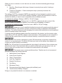
FASTENING THE INVERTER TO A FLAT SURFACE4.
For convenience your inverter can be fastened to a at surface, horizontally or vertically. The area
where the inverter is to be fastened must be dry, well ventilated and away from any combustible
material or fumes.
Turn off and disconnect the inverter.1.
Place the back of the inverter with the mounting bracket against a secure and at surface.2.
Attach the inverter to the at surface using corrosion resistant screws.3.
CONNECTING INVERTER CABLES5.
The inverter and power source must be in the OFF mode.
Make sure you connect your inverter to a 12-volt power supply only.
INVERTER CONNECTION:
NOTE: Determine whether you will be using the battery clips (425 watt output maximum) or the
12V accessory plug (100 watts maximum).
Locate the positive and negative plastic terminals located on the right side of the inverter 1.
and remove the terminal caps completely.
Install the positive (red) cable ring lug onto the positive (red) terminal screw. Install the 2.
negative (black) cable ring lug onto the negative (black) terminal screw. Tighten each
terminal so that the cable cannot come loose.
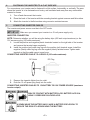
CONNECTING INVERTER CABLE TO A VEHICLE (100 watts maximum):
DC Outlet
DC Plug
Remove the cigarette lighter from its outlet.1.
Push the 12-volt power plug rmly into the outlet.2.
CONNECTING INVERTER CABLES TO 12V BATTERY OR 12V POWER SOURCE (maximum
inverter output):
RISK OF CONTACT WITH BATTERY ACID. BATTERY ACID IS A
HIGHLY CORROSIVE SULFURIC ACID.
A SPARK NEAR THE BATTERY MAY CAUSE A BATTERY EXPLOSION. TO
REDUCE THE RISK OF A SPARK NEAR THE BATTERY:

• 5 •
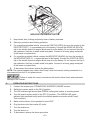
NEGATIVE GROUNDED SYSTEM
Keep hands, hair, clothing and jewelry clear of battery terminals.1.
Wear eye protection and clothing protection.2.
For a negative-grounded vehicle, connect the POSITIVE (RED) clip from the inverter to the 3.
POSITIVE (POS, P, +) ungrounded post of the battery. Connect the NEGATIVE (BLACK)
clip to the vehicle chassis or engine block away from the battery. Do not connect the clip to
the carburetor, fuel lines or sheet-metal body parts. Connect to a heavy gauge metal part
of the frame or engine block.
For a positive-grounded vehicle, connect the NEGATIVE (BLACK) clip from the inverter to 4.
the NEGATIVE (NEG, N, -) ungrounded post of the battery. Connect the POSITIVE (RED)
clip to the vehicle chassis or engine block away from the battery. Do not connect the clip to
the carburetor, fuel lines or sheet-metal body parts. Connect to a heavy gauge metal part
of the frame or engine block.
To disconnect the inverter, reverse the above steps.5.
NOTE: The internal speaker may make a brief “beep” when the inverter is being connected to or
disconnected from the 12-volt power source.
Failure to make the correct connections will result in blown fuses and permanent
damage to the inverter.
OPERATING INSTRUCTIONS6.
Connect the inverter (see “CONNECTING INVERTER CABLES” section.1.
Switch the inverter switch to the ON (I) position.2.
The LED indicator light should glow GREEN verifying the inverter is receiving power.3.
Turn the inverter rocker switch to the OFF (O) position. (The GREEN LED power 4.
indicator light may ash briey and/or the internal speaker may make a brief “beep”.
This is normal.).
Make sure the device to be operated is turned OFF.5.
Plug the device into the inverter AC outlet.6.
Turn the inverter on.7.
Turn the device on.8.
To disconnect, reverse the above procedure.9.

• 6 •
NOTE: If more than one device is to be powered, start one device at a time to avoid a power
surge and overloading the inverter. The surge load of each device should not exceed the inverters
Continuous Operation wattage rate.
If you are using the power inverter to operate a battery charger, monitor the
temperature of the battery charger for about 10 minutes. If the battery charger becomes
abnormally warm, disconnect it from the inverter immediately.
NOTE: You can use an extension cord from the inverter to the device without signicantly
decreasing the power being generated by the inverter. Use a 18 gauge (AWG) (1.75mm
2
)
extension cord. For best operating results, the extension cord should be no longer than 50 feet
(15 meters).
Using the Inverter to Operate a TV or Audio Device:
The inverter is shielded and ltered to minimize signal interference. Despite this, some interference
may occur with your television picture, especially with weak signals. Below are some suggestions
to try and improve reception.
Make sure the television antenna produces a clear signal under normal operating 1.
conditions (i.e. at home plugged into a standard 120-volt AC wall outlet). Also, ensure that
the antenna cable is adequately shielded and of good quality.
Try altering the position of the inverter, antenna cables, and television power cord. Add 2.
an extension cord from the inverter to the TV so as to isolate its power cord and antenna
cables from the 12-volt power source.
Try coiling the television power cord and the input cables running from the 12-volt power 3.
source to the inverter.
Afx one or several “Ferrite Data Line Filters” to the television power cord. Ferrite Data 4.
Line Filters can be purchased at most electronic supply stores.
Try grounding the inverter with an 18 AWG (minimum) (0.75mm5.
2
) wire, using as short a
length as possible.
NOTE: You may hear a “buzzing” sound being emitted from inexpensive sound systems when
operated with the inverter. This is due to ineffective lters in the sound system’s power supply.
Unfortunately, this problem can only be resolved by purchasing a sound system with a higher
quality power supply or higher quality lter.
POWER SOURCE7.
When operating a device that draws approximately 60 watts, your average automobile or marine
battery at full charge will provide an ample power supply to the inverter for approximately 3 hours
when the engine is off. The actual length of time the inverter will function depends on the age and
condition of the battery and the power demand being placed by the device being operated with
the inverter.
If you decide to use the inverter while the engine is off, we recommend you turn OFF the device
plugged into the inverter and disconnect the inverter’s plug from the 12-volt accessory outlet before
starting the engine. To maintain battery power, start the engine every 2 to 3 hours and let it run for
approximately 30 minutes to recharge the battery.
Although it is not necessary to disconnect the inverter when turning over the engine, it may briey
cease to operate as the battery voltage decreases. While the inverter draws very low amperage
when not in use, it should be unplugged to avoid battery drain.

• 7 •
LED INDICATOR AND SHUTDOWN PROTECTION8.
The LED glows GREEN automatically when plugged into a 12-volt DC source and will not glow
under the following conditions:
When the power input from the vehicle’s battery drops to approximately 10.5-volts, low 1.
battery shutdown occurs and inverter shuts off. Solution: Recharge or Replace the battery.
When the power input from the vehicle’s battery exceeds 15-volts, high voltage overload 2.
protection occurs. Solution: Reduce the voltage range to between 12-volts and 14-volts.
The continuous load demand from the equipment or device being operated exceeds the 3.
continuous load rating of the inverter being used. Solution: Use a higher capacity inverter
or lower rated device.
The case temperature becomes hot (exceeds 145°F). Solution: Allow the inverter to cool. 4.
Do not block the cooling slots or air ow over and through the inverter. Reduce the load on
the inverter to the continuous rated output.
RESET: To reset after shutdown occurs, switch the inverter On/Off switch to the OFF position.
Check the source of the problem and correct. Switch the inverter On/Off switch to the ON position.
NOTE: If the red LED is lit and the green LED is not, see the Troubleshooting section.
IF THE INVERTER FUSE BLOWS9.
Your power inverter is tted with a fuse, which should not have to be replaced under normal
operating conditions. A blown fuse is usually caused by reverse polarity or a short circuit within the
device or equipment being operated.
If the fuse does blow:
Disconnect the device or equipment immediately.1.
Find the source of the problem, and repair it.2.
Install a new 25-amp fuse. The fuses can be found on the right side of the inverter.3.
Do not install a fuse higher than 25-amp, as this may damage the inverter and any
product you use with the inverter. Make sure to correct the cause of the blown fuse before using
the inverter again.

• 8 •
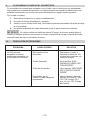
TROUBLESHOOTING10.
PROBLEM REASON SOLUTION
Red LED is on, audible
alarm is on, and/or inverter
does not function.
Poor contact at terminals.
Fuse Blown.
Inverter shutdown.
Inverter may not be working
properly.
Unplug and reinsert the
12-volt plug or check
connections at power supply.
See “IF THE INVERTER
FUSE BLOWS” section.
See “LED INDICATOR AND
SHUTDOWN PROTECTION”
section.
See Warranty and call
Customer Service 1-800-
732-7764 (Hours: 7 am – 5
pm CST).
The red LED is lit and the
green LED is not.
12V Accessory Plug or
Clips are not making a good
connection to the battery.
Connections are reversed.
Inverter may not be working
properly.
Check for poor connection to
battery and frame. Make sure
connection points are clean.
Rock clips back and forth for
a better connection.
Unplug the charger and
reverse the clips.
See Warranty and call
Customer Service 1-800-
732-7764 (Hours: 7 am – 5
pm CST)
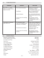
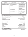
SPECIFICATIONS11.
Maximum Continuous Power 425 Watts
Surge Capability (Peak Power) 850 Watts
No Load Current Draw <0.4A
Wave Form Modied Sine Wave
Input Voltage Range 10.5V – 15.5V DC
Output Voltage Range 110V ± 5% AC
Low Battery Alarm Audible, 11V ± 0.3V DC
Low Battery Shutdown 10.5V ± .3V DC
High Battery Shutdown 15.5V ± 0.5V DC
Optimum Efciency 85%
AC Outlet Two, NEMA 5 - 15 USA
Fuse Two, 25-Amp (Spade Type)
Dimensions 6.5” L x 4.13” W x 2.2” H
Weight approximately 2 lbs.

• 9 •
REPLACEMENT PARTS12.
12V Accessory Plug with Cables 38-99-002175
Battery Cable with Clips 38-99-001512

• 10 •
IMPORTANTE: LEA Y GUARDE ESTE MANUAL DE INSTRUCCIONES Y SEGURIDAD.
GUARDE ESTAS INSTRUCCIONES: El 71496 ofrece una amplia gama de características
para satisfacer sus necesidades. Este manual le mostrará cómo utilizar su convertidor en
forma segura y efectiva. Por favor, lea, comprenda y siga estas instrucciones y precauciones
cuidadosamente, ya que este manual contiene instrucciones operativas y de seguridad de
importancia. Los mensajes de seguridad representados en este manual contienen palabras
guía, un mensaje y una gura.
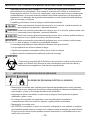
La palabra guía indica el nivel de peligro en determinada situación.
Indica una inminente situación de riesgo que, si no se evita, resultaría mortal o de
serios perjuicios al operador o personas alrededor.
Indica una situación potencialmente riesgoso que, si no se evita, podría resultar o de
serios perjuicios al operador o personas alrededor.
Indica una situación potencialmente peligrosa que, de no evitarse, podría resultar en
menores o serio daños al usuario y terceras personas.
Indica una situación potencialmente peligrosa que, de no evitarse, podría causar
daño al equipo, al vehículo y propiedades alrededor.
Los mensajes estipulados en este manual se describen dos tipos de estilo.
Los que aparecen sin número indican el riesgo.•
Aquellos que aparecen numerados, indican cómo evitar los riesgos.•
La gura muestra una descripción gráca del potencial de riesgo.
Conforme a la propuesta 65 de California, este producto contiene químicos de los
cuales en el Estado de California se tiene conocimiento que provocan cáncer y
malformaciones congénitas u otras lesiones reproductivas.
INSTRUCCIONES IMPORTANTES DE SEGURIDAD1.
EL RIESGO DE DESCARGA ELÉCTRICA O INCENDIO
Mantenga el convertidor bien ventilado para dispersar apropiadamente el calor generado •
cuando está en uso. Asegúrese de que haya varias pulgadas de libramiento alrededor de la
parte superior y lados y no bloquee las ranuras del convertidor.
Asegúrese de que el convertidor no esté cerca de ninguna fuente potencial de gases •
inamables, gases o ropa.
No coloque el convertidor en áreas tales como compartimientos de baterías o •
compartimientos del motor donde los vapores o gases pueden acumularse.
Mantenga el convertidor seco.•
NO OPERE el convertidor si usted, el convertidor, el dispositivo a ser operado o cualquier •
otra supercie puede entrar en contacto con cualquier fuente de energía que está húmeda.
El agua y muchos otros líquidos pueden conducir electricidad, lo cual puede llevar a una
lesión seria o la muerte.
PELIGRO
ADVERTENCIA
ATENCIÓN
IMPORTANTE
ADVERTENCIA

• 11 •
NO OPERE el convertidor si usted, el convertidor, el dispositivo a ser operado o cualquier •
otra supercie que puede entrar en contacto con cualquier fuente de energía está húmeda.
El agua y muchos otros líquidos pueden conducir electricidad, lo cual puede llevar a una
lesión seria o la muerte.
No coloque el convertidor sobre o cerca de ventilas de calefacción, radiadores u otras fuertes •
de calor o materiales inamables.
No coloque el convertidor en la luz directa del sol. La temperatura del aire ideal para la •
operación es entre 50° y 80°F.
Solamente conecte el convertidor de energía a una toma de corriente accesoria de 12V o a •
una toma de energía de 12V en un avión. No intente conectar el convertidor a cualquier otra
fuente de energía, incluyendo una fuente de energía de CA (corriente alterna). El conectarlo
a una batería de 6 V o 16 V dañará el convertidor.
Asegúrese de que la clavija de CA estén ajustadas.•
No modique el inversor de ninguna forma, incluyendo los cables, enchufes, interruptores o •
receptors de CA, esto podría causar serios daños personales o materiales.
No trate de extender o cambiar de forma alguna los cables de entrada que vienen con el •
inversor.
La operación incorrecta de su convertidor puede resultar en daño y lesión personal. •
ADVERTENCIA
La salida del convertidor es de 110 V CA y puede dar una descarga o
electrocutar igual que cualquier toma de corriente de pared doméstica de CA ordinaria.
No utilice el inversor con un producto que absorba mayor cantidad de watts que el inversor •
pueda proveer, esto podría causar daño al inversor y al producto.
No abrir - No contiene partes que el usuario pueda reparar.•
Este dispositivo no incluye un Interruptor de Circuito con Conexión a Tierra (GFCI por sus •
siglas en inglés) interno.
Use solamente fusibles de 25 amp.•
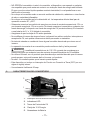
CARACTERÍSTICAS DEL CONVERTIDOR2.
Interruptor de ENCENDIDO/APAGADO (ON/OFF)1.
Indicadoras LED2.
Tomas de Corriente de CA3.
Clavija de 12 V Energía4.
Abrazaderas de Batería5.
1
2
3
4
5

• 12 •
ANTES DE USAR SU CONVERTIDOR DE ENERGÍA3.
NOTA: Este inversor está diseñado para ser usado con una sola batería, de hasta el tipo del grupo
31 (de medida chica o de 130h).
NOTA: No utilice el inversor con un producto que absorba mayor cantidad de watts que el inversor
pueda proveer, esto podría causar daño al inversor y al producto.
Cuando usted enciende un dispositivo o una herramienta que funciona con un motor, el dispositivo
básicamente pasa a través de dos etapas:
Arranque - Requiriendo una subida inicial de voltaje (comúnmente conocida como "carga 1.
de inicio o pico").
Operación Continua - el consumo de energía desciende (comúnmente conocido como la 2.
"carga continua").
El vataje (WATTS) o amperaje (AMPS) pueden ser encontrados normalmente estampados o
impresos en la mayoría de los dispositivos y equipo, o en el manual del usuario. Por lo demás,
comuníquese con el fabricante para averiguar si el dispositivo que usted quiere usar es compatible
con una onda senoidal modicada.
Para calcular el vataje: Vataje = AMPS x 120 (Voltaje CA).
Para calcular la carga de arranque: Carga de Arranque = 2 x WATTS. En general, la carga de
arranque del dispositivo o herramienta eléctrica determina si su convertidor tiene la capacidad de
hacerlo funcionar.
Para calcular la carga continua: Carga Continua = AMPS x 120 (Voltaje CA).
IMPORTANTE
Siempre corra una prueba para establecer si el convertidor operará una pieza
particular de equipo o dispositivo. En caso de una sobrecarga de corriente, el convertidor está
diseñado para apagarse automáticamente. Ésa característica de seguridad evitar dañar el
convertidor mientras se prueban dispositivos y equipo dentro del ámbito de vataje del convertidor.
Si un dispositivo no funciona apropiadamente cuando se conecta por primera vez al convertidor,
de vuelta al interruptor broker a ENCENDIDO (ON) (I), APAGADO (OFF) (O) y nuevamente
ENCENDIDO (ON) (I) en rápida sucesión. Si este procedimiento no tiene éxito, es probable que el
convertidor no tenga la capacidad requerida para operar el dispositivo en cuestión.
IMPORTANTE
Este inversor está diseñado para operar aparatos de 100 watts o menos usado el
Puerto de 12 voltios. Para utilizar la salida completa, usted debe usar el adaptador de las pinzas
de la batería y así conectar el inversor directamente a la batería.
NOTA: El límite de 100 watts es para adaptar la proporción del fusible a todos los vehículos.
Algunos vehículos pueden permitir la salida. Si el fusible se funde cuando cambie al aparato
que intenta usar, solo tiene dos opciones: Usar un aparato más pequeño o conectar el inversor
directamente a la batería.
IMPORTANTE
Este inversor usa ondas solenoids. Por lo tanto, no recomendamos para operar
los siguientes aparatos:
Fuentes energía de en forma de conmutador.1.
Líneas de corriente eléctrica2.
Transformadores clase23.
Condensadores de capacidad4.
Motores ligeros.5.
Motores de ventilador6.

• 13 •
Hornos de microondas7.
Lámparas ourescentes y de alta intensidad (con balastra); y8.
Cargadores de Baterías sin tranformador.9.
Al hacerlo, podría operar el aparato bajo intenso calor y sobrecalentarlo.
PARA SUJETAR EL CONVERTIDOR A UNA SUPERFICIE PLANA4.
Por comodidad su convertidor puede ser sujetado a una supercie plana, horizontal o
verticalmente. El área donde el convertidor será sujetado debe ser seca, bien ventilada y estar
alejada de cualquier material o gases combustibles.
Apague y desconecte el convertidor.1.
Coloque la parte posterior del convertidor con el soporte de montaje contra una supercie 2.
segura y plana.
Sujete el convertidor a la supercie plana usando tornillos resistentes a la corrosión3.
PARA CONECTAR LOS CABLES DEL CONVERTIDOR5.
El convertidor y la fuente de energía deben estar en el modo APAGADO (OFF).
IMPORTANTE
Asegúrese de conectar su convertidor a una fuente de energía de 12V solamente.
CONEXIÓN DEL CONVERTIDOR:
NOTA: Determine si usara las abrazaderas de la batería (salida máxima de 425 watts) o la clavija
accesoria de 12V (máximo 100 watts).
Ubique las terminales plásticas positiva y negativa localizadas en el lado derecho del 1.
convertidor y quite completamente las tapas de las terminales.
Instale el anillo del cable positivo (rojo) en el tornillo de la terminal positiva (roja). Instale el 2.
anillo del cable positivo (negro) en el tornillo de la terminal positiva (negra). Apriete cada
terminal para que el cable no pueda soltarse.
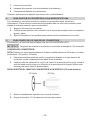
PARA CONECTAR EL CABLE DEL CONVERTIDOR A UN VEHÍCULO (100 watts máximo):
DC Outlet
DC Plug
Quite el encendedor de cigarrillos de su toma de corriente.1.
Empuje la clavija de 12 V rmemente en la toma de corriente.2.

• 14 •
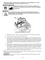
PARA CONECTAR LOS CABLES DEL CONVERTIDOR A UNA BATERÍA DE 12V O UNA
FUENTE DE ENERGÍA DE 12V (máxima salida del inversor):
RIESGO DE CONTACTO CON EL ÁCIDO DE LA BATERÍA. EL
ÁCIDO DE LA BATERÍA ES UN ÁCIDO SULFÚRICO ALTAMENTE
CORROSIVO.
UNA CHISPA PROVOCADA CERCA DE LA BATERÍA PUEDE CAUSAR LA
EXPLOSIÓN DE LA BATERÍA. PARA REDUCIR EL RIESGO DE PROVOCAR
CHISPAS CERCA DE LA BATERÍA:
NEGATIVE GROUNDED SYSTEM
Mantenga las manos, cabello, ropa y joyería alejados de las terminales de la batería.1.
Usé protección para ojos y protección para la ropa.2.
En un vehículo con descarga a tierra por borne negativo, conecte el gancho POSITIVO 3.
(ROJO) del convertidor de batería al borne POSITIVO (POS, P, +) sin descarga a tierra
de la batería. Conecte el gancho NEGATIVO (NEGRO) al chasis del vehículo o al bloque
motor alejado de la batería. No conecte el gancho al carburador, líneas de combustible o
cuerpos metálicos. Conecte a una pieza metálica de calibre grueso del marco o del
bloque motor.
En un vehículo con descarga a tierra por borne positivo, conecte el gancho NEGATIVO 4.
(NEGRO) del convertidor de batería al borne NEGATIVO (NEG, N, -) sin descarga a tierra
de la batería. Conecte el gancho POSITIVO (ROJO) al chasis del vehículo o al bloque
motor alejado de la batería. No conecte al carburador, líneas de combustible o cuerpos
metálicos. Conecte a una pieza metálica de calibre grueso del marco o del bloque motor.
Para desconectar el convertidor, invierta los pasos anteriores.5.
NOTA: La bocina interna puede hacer breve “bip” cuando el convertidor está siendo conectado a o
desconectado de la fuente de energía de 12V.
IMPORTANTE
El no hacer las conexiones correctas resultará en fusibles quemados y daño
permanente el convertidor.

• 15 •
INSTRUCCIONES DE OPERACIÓN6.
Conecte el convertidor (ver la sección “PARA CONECTAR LOS CABLES 1.
DEL CONVERTIDOR”).
Cambie el interruptor del convertidor a la posición de ENCENDIDO (ON) (I).2.
La luz del indicador LED debe brillar VERDE vericando que el convertidor está 3.
recibiendo energía.
Cambie el interruptor de balancín del convertidor a la posición de APAGADO (OFF) (O). 4.
(El indicador de energía LED VERDE puede parpadear brevemente y/o la bocina interna
puede hacer un breve “bip”. Esto es normal.).
Asegúrese de que el dispositivo a ser operado este APAGADO (OFF).5.
Conecte el dispositivo en la toma de corriente CA del convertidor.6.
Encienda el dispositivo.7.
Enciende el dispositivo.8.
Para desconectar, invierta el procedimiento anterior.9.
NOTA: Si se va a dar energía a más de un dispositivo, inicie un dispositivo a la vez para evitar una
sobretensión de energía y sobrecargar el convertidor. La sobretensión de cada dispositivo no debe
exceder el ámbito de vataje de Operación Continúa el convertidor.
IMPORTANTE
Si usted usando el convertidor de energía para operar un cargador de baterías,
monitoree la temperatura del cargador de baterías por aproximadamente 10 minutos. Si el cargado
de graderías se pone anormalmente caliente, desconéctelo del convertidor inmediatamente.
NOTA: Se puede utilizar una extensión del Inversor al aparato sin causar signicante pérdida de
poder generado por el inversor. Se recomienda una extensión de calibre 18 (AWG) de (0.75mm
2
)
Para obtener mejores resultados, la extensión no debe sobrepasar 50 pies (15 metros).
Para Usar El Convertidor Para Operar Una Televisión O Dispositivo De Sonido:
El convertidor está protegido y ltrado para minimizar la interferencia con la señal. A pesar de
esto, alguna interferencia puede ocurrir con la imagen de su televisión, especialmente con señales
débiles. Abajo y algunas sugerencias para tratar y mejorar la recepción.
Asegúrese de que la antena de televisión produzca una señal clara bajo condiciones 1.
normales de operación (Ej. en casa conectado en una toma de corriente de pared
estándar de 120 V de CA). También, asegúrese de que el cable de la antena este
protegido adecuadamente y que sea de buena calidad.
Trate de alterar la posición del convertidor, los cables de la antena y el cable de corriente 2.
de la televisión. Agregue un cable de extensión del convertidor a la televisión para aislar el
cable de energía y los cables de la antena de la fuente de energía de 12V.
ntente enrollar el cable de energía de la televisión y los cables de aporte que van de la 3.
fuente de energía de 12V al convertidor.
Fije uno o varios “Filtros de Línea de Datos de Ferrita” al cable de energía de la televisión. 4.
Los Filtros de Línea de Datos de Ferrita pueden comprarse la mayor parte de las tiendas
de partes electrónicas.
Intente conectar a tierra el convertidor con un alambre de 18 AWG (medida de cable 5.
americana) (mínimo) (0.75mm
2
), usando un tramo tan corto como sea posible.

• 16 •
NOTA: Usted puede escuchar un sonido de “zumbido” siendo emitido de sistemas de sonido
baratos cuando son operados con el convertidor. Esto es debido a ltros inefectivos en el
abastecimiento de energía del sistema de sonido. Lamentablemente, este problema solamente
puede ser resuelto comprando un sistema de sonido con una calidad más alta de abastecimiento
de sonido o un ltro de más alta calidad.
FUENTE DE ENERGÍA7.
Cuando se opere un aparato que absorve aproximadamente 60 watts, su batería de automóvil
o marina promedio a toda carga proporcionará un abastecimiento de energía amplio para él
convertidor por aproximadamente dos a tres horas cuando el motor está apagado. El tiempo total
que el convertidor funcionará depende de la edad y condición de la batería y de la demanda de
energía colocada por el dispositivo siendo operado con el convertidor.
Si decide usar el convertidor mientras el motor está apagado, le recomendamos que apague el
dispositivo conectado al convertidor antes de arrancar el motor. Para mantener la energía de la
batería, arranque el motor cada hora o dos y déjelo encendido por aproximadamente 30 minutos
para recargar la batería.
Aunque no es necesario desconectar el convertidor cuando arranca de nuevo el motor, puede
dejar de operar brevemente mientras disminuye el voltaje de la batería. Aunque el convertidor
extrae muy poco amperaje cuando no está en uso, debe ser desconectado para evitar descargar
la batería.
INDICADOR LED Y PROTECCIÓN DE DE APAGADO8.
El LED brilla VERDE automáticamente cuando se conecta a una fuente de 12V de CD y no brillará
bajo las siguientes condiciones:
Cuando la aportación de energía de la batería del vehículo disminuye aproximadamente 1.
10.5V, o un apagado por batería baja y el convertidor se apaga. Solución: Recargue o
Reemplace la batería.
Cuando la aportación de energía de la batería del vehículo excede 15 V, la protección de 2.
sobrecarga de alto voltaje ocurre. Solución: Reducir el ámbito de voltaje a entre
12V y 14V.
La demanda de carga continua del equipo o dispositivo siendo operado excede 3.
la clasicación de carga continua del convertidor siendo usado. Solución: Usar un
convertidor de mayor capacidad o un dispositivo de clasicación más baja.
La temperatura de la caja se pone caliente (excede los 145 °F). Solución: Permita que 4.
el convertidor se enfríe. No bloquee las ranuras de enfriamiento o el ujo de aire sobre
y a través del convertidor. Reduzca la carga sobre el convertidor a la salida continua
clasicada.
RESTABLECER: Para restablecer después de que ocurre el apagado, cambie el interruptor On/
Off a la posición de OFF. Identique el origen del problema y corríjalo. Cambie el inversor a la
posición ON.
NOTA: Si la luz LED roja está encendida y la luz verde no, consulte la sección de localización y
solución de problemas.

• 17 •
SI SE QUEMA EL FUSIBLE DEL CONVERTIDOR9.
Su convertidor de corriente está equipado con un fusible, que no tendría que ser reemplazado
bajo condiciones normales de operación. Un fusible quemado es causado usualmente por una
polaridad inversa como un cortocircuito dentro del dispositivo o equipo siendo operados.
Si el fusible se quema:
Desconecte el dispositivo o equipo inmediatamente.1.
Encuentra la fuente del problema, y repárela.2.
Instale un nuevo fusible de 25 amp. Los fusibles puede ser encontrado al nal de la clavija 3.
en el convertidor.
No apriete la tapadera del fusible demasiado justa; el ajuste manual es suciente.4.
IMPORTANTE
No intente instalar un fusible de más de 25 amps, ya que esto podría dañar el
inversor y cualquier producto que use con el inversor. Asegúrese de corregir la causa del fusible
quemado antes de usar el convertidor de nuevo.
RESOLUCIÓN DE PROBLEMAS10.
PROBLEMA CAUSA POSIBLE SOLUCION
La LED roja está
encendida, la alarma
audible está encendida, y/o
el convertidor no funciona..
Mal contacto en las
terminales.
Fusible Quemado.
Cierre del convertidor.
Es probable que el
inversor no esté trabajando
propiamente.
Desconecte y vuelva a
reinsertar la clavija de 12V
o revise las conexiones a la
fuente de energía.
Ver la sección “SI SE
QUEMA EL FUSIBLE DEL
CONVERTIDOR”.
Ver la sección “INDICADOR
LED Y PROTECCIÓN DE
CIERRE”.
Vea la Garantía y llame al
Servicio al Cliente al 1-800-
732-7764 (Horario: De 7
a.m. a 5 p.m. CST (Tiempo
del Centro))

• 18 •
PROBLEMA CAUSA POSIBLE SOLUCION
La luz LED roja está
encendida y la luz verde no.
La Clavija Accesoria de
12V o Los ganchos no se
encuentran bien conectados
a la batería.
Las conexiones se
encuentran invertidas.
Es probable que el
inversor no esté trabajando
propiamente.
Verique la posible
presencia de una conexión
defectuosa a la batería o
al bastidor. Asegúrese de
que los puntos de conexión
estén limpios. Mueva los
ganchos hacia adelante y
hacia atrás para lograr una
mejor conexión.
Desenchufe el cargador e
invierta los ganchos.
Vea la Garantía y llame al
Servicio al Cliente al 1-800-
732-7764 (Horario: De 7
a.m. a 5 p.m. CST (Tiempo
del Centro))
ESPECIFICACIONES11.
Máxima Energía Continua 425 Watts
Capacidad de Tensión (Potencia Máxima) 850 Watts
Consumo de Corriente en Vacío <0,4A
Forma de Onda Onda Senoidal Modicada
Ámbito de Tensión de Entrada 10.5V a 15.5V DC
Ámbito de Tensión de Salida 110V ± 5% AC
Alarma de Batería Baja Audible, 11V ± 0.3V CD
Cierre por Batería Baja 10.5V ± 0.3V DC
Cierre por Batería Alta 15.5V ± 0.5V DC
Óptima Eciencia 85%
Toma de Corriente CA Dos, NEMA 5 - 15 USA
Fusible Dos, 25 amp (Tipo Espada)
Dimensiones 6.5” L x 4.13” A x 2.2” P
Peso Aproximadamente 2 libras
PIEZAS DE REPUESTO12.
Clavija Accesoria de 12 V con Cables 38-99-002175
Cable de Batería con Abrazaderas 38-99-001512
-
 1
1
-
 2
2
-
 3
3
-
 4
4
-
 5
5
-
 6
6
-
 7
7
-
 8
8
-
 9
9
-
 10
10
-
 11
11
-
 12
12
-
 13
13
-
 14
14
-
 15
15
-
 16
16
-
 17
17
-
 18
18
-
 19
19
-
 20
20
-
 21
21
-
 22
22


DieHard 71496 El manual del propietario
- Categoría
- Adaptadores de corriente
- Tipo
- El manual del propietario
en otros idiomas
- English: DieHard 71496 Owner's manual
Artículos relacionados
Otros documentos
-
Schumacher DieHard 71522 140W Power Inverter El manual del propietario
-
-
Schumacher Electric PI-750 Manual de usuario
-
Schumacher Electric XI14 El manual del propietario
-
-
-
-
-