
REV 012A
High
Quality
Nautical
Equipment
Manuale d'uso SALPA ANCORA VERTICALI
User's Manual VERTICAL WINDLASSES
Manuel de l'utilisateur GUINDEAUX VERTICAUX
Benutzerhandbuch VERTIKAL ANKERWINDEN
Manual del usuario MOLINETES VERTICALES
ARIES FLAIR RIDER
700/1000/1400W
A 712 A 712 D
A 724 A 724 D
A 1012 A 1012 D
A 1024 A 1024 D
A 1412 A 1412 D
A 1424 A 1424 D
F 712 F 712 D
F 724 F 724 D
F 1012 F 1012 D
F 1024 F 1024 D
F 1412 F 1412 D
F 1424 F 1424 D
R 712 R 712 D
R 724 R 724 D
R 1012 R 1012 D
R 1024 R 1024 D
R 1412 R 1412 D
R 1424 R 1424 D
IT
GB
FR
DE
ES


AFR 700/1000/1400W - REV012A
3
Pag. 4 Caratteristiche tecniche
Pag. 5 Installazione
Pag. 6 Schema di collegamento
Pag. 7 Uso - Avvertenze importanti
Pag. 8/9 Manutenzione
Pag. 10/11 Set
Pag. 12 Technical data
Pag. 13 Installation
Pag. 14 Connection diagram
Pag. 15 Usage - Warning
Pag. 16/17 Maintenance
Pag. 18/19 Set
Pag. 20 Caractéristiques techniques
Pag. 21 Installation
Pag. 22 Schéma de cablage
Pag. 23 Utilisation - Avvertissements importants
Pag. 24/25 Entretien
Pag. 26/27 Groupe
Seite 28 Technische Eigenschaften
Seite 29 Montage
Seite 30 Anschlussplan
Seite 31 Gebrauch - Wichtige Hinweise
Seite 32/33 Wartung
Seite 34/35 Gruppe
Pág. 36 Características técnicas
Pág. 37 Instalación
Pág. 38 Esquema de montage
Pág. 39 Uso - Advertencias importantes
Pág. 40/41 Mantenimiento
Pág. 42/43 Grupo
INDICE
INDEX
SOMMAIRE
INHALTSANGABE
INDICE
IT
GB
FR
DE
ES

4
CARATTERISTICHE TECNICHE
AFR 700/1000/1400W - REV012A
IT
C
E
H
I
A
B
D
F
A
C
D
E
F
G
H
B
I
700 / 1000 / 1400 W ARIES - FLAIR - / D 700 / 1000 / 1400 W RIDER - / D
• (5) Su richiesta possono essere forniti alberi e prigionieri per spessori di coperta maggiori.
1° ESEMPIO: FLAIR724D
FLAIR 7 24 D
a
RIDER 10 12 -
Nome della serie:
[ ARIES ] =
base ovale in alluminio
[ FLAIR B ] =
base ovale in fibra nera
[ FLAIR W ] =
base ovale in fibra bianca
[ RIDER ] =
base circolare in alluminio
Potenza motore:
[ 7 ] =
700 W
[ 10 ] =
1000 W
[ 14 ] =
1400 W
Tensione alimentazione
motore:
[ 12 ] =
12 V
[ 24 ] =
24 V
Campana:
[ D ] =
con campana
[ - ] =
senza campana
COME SI LEGGE IL MODELLO DEL SALPA ANCORA:
a b c d
a b c d a b c d
2° ESEMPIO: RIDER1012
a
a
a
a
a
a
a
• (1) Dopo un primo periodo d’uso. • (2) Misure effettuate con barbotin per catena da 8 mm.
• (3) Valore minimo consigliato per una lunghezza totale L<20m (Vedi pag. 44). Calcolare la sezione in funzione della lunghezza del collegamento.
• (4) Con interruttore specifi co per correnti continue (DC) e ritardato (magneto-termico o magneto-idraulico).
DIMENSIONI
mm (inch)
ARIES/FLAIR - / D RIDER - / D ARIES/FLAIR - / D RIDER - / D
700W 1000W 700W 1000W 1400W
A
98 (3” 27/32) 100 (3” 15/16) 98 (3” 27/32) 100 (3” 15/16)
B
161,4 (6” 23/64) 163,4 (6” 7/16) 161,4 (6” 23/64) 163,4 (6” 7/16)
C
141 (5” 9/16) 179 (7”) 179 (7”)
D
250 (9” 27/32) 159 (6” 1/4) 250 (9” 27/32) 159 (6” 1/4)
E
141 (5” 9/16) 167 (6” 37/34)
F
87 (3” 7/16) Ø 155 (6” 3/32) 87 (3” 7/16) Ø 155 (6” 3/32)
G
78 (3” 23/32) - 78 (3” 23/32) -
H
330 (13”) 340 (13” 3/8) 330 (13”) 340 (13” 3/8) 375 (14” 49/64)
I
25 ÷ 50 mm (31/32” ÷ 1” 31/32)
(5)
30 ÷ 50 mm (1”3/32 ÷ 1” 31/32)
(5)
MODELLI ARIES – / D FLAIR – / D RIDER – / D
POTENZA MOTORE W 700 1000 1400 700 1000 1400 700 1000 1400
Tensione motore V 12 24 12 24 12 24 12 24 12 24 12 24 12 24 12 24 12 24
Tiro istantaneo massimo
kg 850 1000 1100 850 1000 1100 850 1000 1100
lb 1873,9 2204,6 2425,1 1873,9 2204,6 2425,1 1873,9 2204,6 2425,1
Carico di lavoro massimo
kg 250 300 370 450 450 500 250 300 370 450 450 500 250 300 370 450 450 500
lb 551,1 661,4 815,7 992,1 992,1 1102,3 551,1 661,4 815,7 992,1 992,1 1102,3 551,1 661,4 815,7 992,1 992,1 1102,3
Carico di lavoro
kg 80 100 120 150 150 170 80 100 120 150 150 170 80 100 120 150 150 170
lb 176,4 220,5 264,5 330,7 330,7 374,8 176,4 220,5 264,5 330,7 330,7 374,8 176,4 220,5 264,5 330,7 330,7 374,8
Assorbimento corrente
al carico di lavoro
(1)
A 90 55 140 80 155 85 90 55 140 80 155 85 90 55 140 80 155 85
Velocità max
di recupero
(2)
m/min 27,4 26,4 39,6 40,9 33,0 29,7 27,4 26,4 39,6 40,9 33,0 29,7 27,4 26,4 39,6 40,9 33,0 29,7
ft/min 89,9 86,6 129,9 134,2 108,3 97,4 89,9 86,6 129,9 134,2 108,3 97,4 89,9 86,6 129,9 134,2 108,3 97,4
Velocità di recupero
al carico di lavoro
(2)
m/min 14,4 14,8 20,4 21,4 17,5 20,5 14,4 14,8 20,4 21,4 17,5 20,5 14,4 14,8 20,4 21,4 17,5 20,5
ft/min 47,2 48,6 66,9 70,2 57,4 67,3 47,2 48,6 66,9 70,2 57,4 67,3 47,2 48,6 66,9 70,2 57,4 67,3
Sezione minima
cavi motore
(3)
mm
2
25 10 35 16 50 25 25 10 35 16 50 25 25 10 35 16 50 25
AWG372503372503372503
Interruttore di protezione
(4)
A 50 40 80 50 100 50 50 40 80 50 100 50 50 40 80 50 100 50
Peso
modello senza campana
kg 17,4 18,5 20,8 16,5 17,6 19,9 16,0 17,1 19,4
lb 38,4 40,8 45,8 36,4 38,8 43,9 35,3 37,7 42,8
Peso
modello con campana
kg 19,3 20,4 22,7 18,4 19,5 21,8 18,0 19,1 21,4
lb 42,5 45,0 50,0 40,6 43,0 48,1 39,7 42,1 47,2
Quick
®
si riserva il diritto di apportare modifiche alle caratteristiche tecniche dell'apparecchio e al contenuto di questo manuale senza alcun preavviso.
In caso di discordanze o eventuali errori tra il testo tradotto e quello originario in italiano, fare riferimento al testo italiano o inglese.
F
(*) Per i codici dei barbotin fare riferimento all’esploso a pag 8.
(**) ISO EN 818-3.
BARBOTIN (*) 6 mm 8 mm - 5/16” 10 mm - 3/8”
Catena supportata
6 mm 6 mm 8 mm 8 mm 5/16” 5/16” 10 mm 10 mm 3/8”
DIN 766 ISO DIN 766 ISO G4 BBB DIN 766 ISO G4
Cima supportata (**) 1/2” 1/2” - 9/16” - 5/8” -

5
INSTALLAZIONE
AFR 700/1000/1400W - REV012A
IT
ATTENZIONE:
prima di effettuare il collegamento accertarsi che non sia presente l'alimentazione su cavi.
PRIMA DI UTILIZZARE IL SALPA ANCORA LEGGERE ATTENTAMENTE IL PRESENTE MANUALE D'USO.
IN CASO DI DUBBI CONSULTARE IL RIVENDITORE QUICK
®
.
ATTENZIONE:
i salpa ancora Quick
®
sono stati progettati e realizzati per salpare l'ancora. Non utilizzare questi apparecchi
per altri tipi di operazioni.
Quick
®
non si assume alcuna responsabilità per i danni diretti o indiretti causati da un uso impro-
prio dell'apparecchio.
Il salpa ancora non è progettato per sostenere carichi generati in particolari condizioni atmosferiche
(burrasca).
Disattivare sempre il salpa ancora quando non è in uso. Accertarsi che non vi siano bagnanti nelle vicinanze
prima di calare l’ancora.
La giunzione tra la cima e la catena deve avere dimensioni ridotte per poter scorrere agevolmente
dentro la sagoma del barbotin. Per qualsiasi problema o richiesta contattare l’assistenza Quick
®
. Per maggiore sicurezza, nel
caso in cui uno si danneggi suggeriamo di installare almeno due comandi per l’azionamento del salpa ancora.
Consigliamo l’uso dell’interruttore magneto-idraulico Quick
®
come sicurezza per il motore. Bloccare la catena con un
fermo prima di partire per la navigazione.
La scatola teleruttori o teleinvertitori deve essere installata in un luogo protetto da
possibili entrate d’acqua.
Dopo aver completato l’ancoraggio, fi ssare la catena o cima a punti fi ssi quali chian stopper o bitta.
Per prevenire rilasci non voluti l’ancora deve essere fi ssata, il salpa ancora non deve essere usato come unica presa di forza.
Isolare il salpa ancora dall’impianto elettrico durante la navigazione (disinserire l’interruttore di protezione del motore) e bloc-
care la catena ad un punto fi sso dell’imbarcazione.
LA CONFEZIONE CONTIENE:
salpa ancora (top + motoriduttore) - cassetta teleruttori - guarnizione della base - dima di foratura - leva
- viterie (per l'assemblaggio) - manuale di istruzioni - condizioni di garanzia.
ATTREZZI NECESSARI PER L'INSTALLAZIONE:
trapano con punte: Aries/Flair/Rider Ø 9 mm (23/64") e Ø 11 mm (7/16");
a tazza: Aries/Flair Ø 53 mm (2”1/16) e Ø 70 mm (2”3/4), Rider Ø 60 mm (2” 23/64); chiave esagonale: 13 mm.
ACCESSORI QUICK
®
CONSIGLIATI:
deviatore da pannello (mod. 800) - Pulsantiera stagna (mod. HRC 1002) - Pulsante a piede (mod.
900) - Interruttore magneto-idraulico - Conta catena per l'ancoraggio (mod. CHC 1102M e CHC 1202M) - Sistema di comando via radio
RRC (mod. R02, PO2, H02).
REQUISITI PER L'INSTALLAZIONE:
il salpa ancora va posizionato allineando il barbotin con il puntale di prua. Verifi care che le
superfi ci superiore e inferiore della coperta siano più parallele possibili; se ciò non dovesse accadere compensare opportunamente la
differenza (la mancanza di parallelismo potrebbe causare perdite di potenza del motore). Lo spessore di coperta dovrà essere compreso
fra i valori indicati in tabella. Se si avessero spessori differenti è necessario consultare il rivenditore Quick
®
. Non devono esistere ostacoli
sotto coperta per il passaggio di cavi, cima e catena, la poca profondità del gavone potrebbe provocare inceppamenti.
PROCEDURA DI MONTAGGIO:
stabilita la posizione ideale praticare i fori utilizzando la dima di foratura fornita a corredo. Rimuo-
vere il materiale in eccesso dal foro di passaggio della catena/cima, rifi nirlo e lisciarlo con un prodotto specifi co (vernice marittima, gel o
resina epossidica) assicurando il libero passaggio della catena/cima. Posizionare la parte superiore, inserendo la guarnizione fra la coper-
ta e la base e collegare a questa la parte inferiore, infi lando l'albero nel riduttore. Fissare il salpa ancora avvitando i dadi sui prigionieri di
bloccaggio. Collegare i cavi di alimentazione provenienti dal salpa ancora al teleruttore.
max
5 mm
(3/16”)
40 cm
(16”)
45°
90°
90°
90°

6
AFR 700/1000/1400W - REV012A
IT
SISTEMA BASE
SCHEMA DI COLLEGAMENTO
GENERALE PAG. 44
PULSANTIERA
MULTIUSO
MOD. HRC 1002
SALPA ANCORA
MOTORE
BATTERIA
INTERRUTTORE
MAGNETO
IDRAULICO
(vedi tabella pag.4)
CASSETTA
TELERUTTORI
MOD. T6315-12 (12V)
MOD. T6315-24 (24V)
C
A2
PULSANTI A PIEDE
MOD. 900U E 900D
NERO
MARRONE
BLU
A1
FUSIBILE
4A (12V)
2A (24V)
L = L1 + L2 + L3 + L4
MARRONE
NERO
BLU
L1
L2
L3
L3
L4
SCHEMA DI COLLEGAMENTO
CONTACATENA
DA PANNELLO
COMANDO
DA PLANCIA
PULSANTIERA
CONTACATENA
TASCABILE - PULSANTIERA
RICEVITORE
ACCESSORI QUICK
®
PER L'AZIONAMENTO
DEL SALPA ANCORA
TRASMETTITORI
RADIOCOMANDI

7
AFR 700/1000/1400W - REV012A
IT
AVVERTENZE IMPORTANTI
ATTENZIONE:
non avvicinare parti del corpo o oggetti alla zona in cui scorrono catena, cima e barbotin.
Accertarsi che non sia presente l’alimentazione al motore elettrico quando si opera manualmente sul
salpa ancora (anche quando si utilizza la leva per allentare la frizione); infatti persone dotate di comando a
distanza del salpa ancora (pulsantiera remota o radiocomando) potrebbero accidentalmente attivarlo.
ATTENZIONE:
bloccare la catena con un fermo prima di partire per la navigazione.
ATTENZIONE:
non attivare elettricamente il salpa ancora con la leva inserita nella campana o nel
coperchio del barbotin.
ATTENZIONE:
Quick
®
consiglia di utilizzare un interruttore specifico per correnti continue (DC) e ritardato
(magneto termico o magneto idraulico) per proteggere la linea del motore da surriscaldamenti o corto-
circuiti. L’interruttore può essere utilizzato per isolare il circuito di comando del salpa ancora evitando così
azionamenti accidentali.
USO DELLA FRIZIONE
Il barbotin (6) è reso solidale all’albero principale (13 o 14) dalla frizione (5). La frizione si apre (stacco) utilizzando
la leva (1) che inserita nella bussola (3) della campana o nel coperchio barbotin (2) dovrà ruotare in senso
antiorario. Ruotando in senso orario si provocherà la chiusura (attacco) della frizione.
PER SALPARE
Accendere il motore dell’imbarcazione. Assicurarsi che la frizione (5) sia serrata ed estrarre la leva (1).
Premere il pulsante UP del comando a vostra disposizione.
Se il salpa ancora si arresta senza che l’interruttore magneto-idraulico (o magnetotermico) sia scattato,
attendere qualche secondo e riprovare (evitare una pressione continuata del pulsante).
Se l’interruttore magneto-idraulico (o magnetotermico) è scattato, riattivare l’interruttore e attendere qualche
minuto prima di riprendere a salpare.
Se, dopo ripetuti tentativi, il salpa ancora continua a bloccarsi consigliamo di manovrare l’imbarcazione per
disincagliare l’ancora.
Controllare la salita degli ultimi metri di catena per evitare danni alla prua.
PER CALARE
La calata dell’ancora si può effettuare tramite comandi elettrici oppure manualmente. Per effettuare l’operazione
manualmente occorre aprire la frizione (5) lasciando libero il barbotin (6) di girare sul proprio asse e trascinare la
catena o la cima in acqua.
Per frenare la caduta dell’ancora bisogna ruotare la leva (1) in senso orario.
Per calare l’ancora elettricamente occorre premere il pulsante DOWN del comando a vostra disposizione. In
questo modo la calata è perfettamente controllabile e lo svolgimento della catena o della cima è regolare.
Per evitare sollecitazioni sul salpa ancora, una volta ancorati, bloccare la catena con un fermo oppure fissarla ad
un punto saldo con una cima.
USO

8
AFR 700/1000/1400W - REV012A
IT
44
45
46
47
48
49
42
43
40
37
35
36
41
40
33
31
38
39
34
32
37
35
36
30
30
38
39
27
26
15
16
17
18
24
23
28
1
19
4
2
6
14
5
7
5
13
3
25
29
15
11
12
11
10
9
8
19
20
21
22
50
POS.
DENOMINAZIONE CODICE
1 Leva salpa piegata ZSLMSHR10000
2 Coperchio barbotin SPMSGB100R02
3 Bussola serie “AL” SGMSDCPAL100
4 Campana salpa “AL” 1000W SPMSE10ALR01
5 Cono frizione MSF100000000
6A Barbotin 6 mm ZSB100600000
6B Barbotin 8 mm-5/16" ZSB1008516R4
6C Barbotin 10 mm-3/8" ZSB1010380AR
7 Magnete KPMC08060000
8 Rondella sagomata MBR254025X00
9 Paraolio PGPRL2547700
10 Anello elastico interno MBAN4717Y000
11 Anello elastico esterno MBAE2520Y000
12 Cuscinetto MBJ60052RS10
13 Albero corto MSAS10274R30
14 Albero lungo MSAS10308R30
15 Chiavetta MBH080780F00
MANUTENZIONE

9
AFR 700/1000/1400W - REV012A
IT
ATTENZIONE:
accertarsi che non sia presente l’alimen-
tazione al motore elettrico quando si opera manualmente
sul salpa ancora; rimuovere con cura la catena o cima dal
barbotin o la cima dalla campana.
I salpa ancora Quick
®
sono costituiti da materiali resistenti all’am-
biente marino: è indispensabile, in ogni caso, rimuovere periodica-
mente i depositi di sale che si formano sulle superfici esterne per
evitare corrosioni e di conseguenza danni all’apparecchio.
Lavare accuratamente con acqua dolce le superfici e le parti in cui
il sale può depositarsi.
Smontare una volta all’anno il barbotin e la campana attenendosi
alla seguente sequenza:
VERSIONE CON CAMPANA
Con la leva (1) svitare la bussola (3); estrarre la campana (4) e il
cono frizione superiore (5); svitare le viti di fissaggio (17 o 27) dello
stacca catena (18 o 26) e rimuoverlo; estrarre il barbotin (6).
VERSIONE SENZA CAMPANA
Con la leva (1) svitare il coperchio barbotin (6); estrarre il cono fri-
zione superiore (5); svitare le viti di fissaggio (17 o 27) dello stacca
catena (18 o 26) e rimuoverlo; estrarre il barbotin (6).
Pulire ogni parte smontata affinché non si verifichino attacchi di
corrosione e ingrassare (con grasso marino) il filetto dell’albero (13
o 14) e il barbotin (5) dove appoggiano i coni frizione (5).
Ingrassare periodicamente il perno (23) del coperchio guida catena
(16) (solamente per salpa ancora con base in alluminio).
Rimuovere eventuali depositi di ossido sui morsetti della
cassetta teleruttori; cospargerli di grasso.
MANUTENZIONE
16A Coperchio guida catena A SGMSGG100000
16B Coperchio guida catena F bianca PDGC10DW0000
16C Coperchio guida catena F nera PDGC10DB0000
17A Vite per base Aries MBV0516MXSC0
17B Vite per base Flair MBV0530MXSC0
18A Stacca catena per base Aries MSN10VXP0000
18B Stacca catena per base Flair MSN10VXD0000
19 Sensore SAKREED00000
20 Vite tendicima MSMVT1000000
21A Leva tendicima nera PDLVTD100000
21B Leva tendicima bianca PDLVTD10W000
22 Molla tendicima MMTND1000000
23 Spina coperchio MSR10X000000
24A Base ovale Aries SGMSC10V0000
24B Base ovale Flair bianca SMPD10VW0000
24C Base ovale Flair nera SMPD10VB0000
25 Base circolare SGMSC10C0000
26 Stacca catena per base Rider MSN10CX00000
27 Vite per base Rider MBV0620MXSC0
28 Guarnizione/dima Aries-Flair PGBSV1000000
29 Guarnizione/dima Rider PGBSC1000000
30 Prigioniero MBP080808X00
31 Guarnizione flangia riduttore
Top 700/1000W PGFLRDTG50000
32 Guarnizione flangia riduttore
Top 1400W PGFLRDTG60000
33 Riduttore 700/1000W Quick SLMR10TG5000
34 Riduttore 1400W Quick SLMR15TG7000
35 Rondella MBR08X000000
36 Rondella dentellata MBR08XDE0000
37 Dado MBD08MXEN000
38 Rondella MBR061815X00
39 Dado autobloccante MBD06MXET000
40 O-ring motoriduttore
700/1000/1400W PGR023000000
41 Chiavetta 5x5x15 MBH050515F00
42A Motore 700W 12V EMF071200000
42B Motore 700W 24V EMF072400000
42C Motore 1000W 12V EMF101200000
42D Motore 1000W 24V EMF102400000
42E Motore 1400W 12V EMF141200000
42F Motore 1400W 24V EMF142400000
43A Carter 700W PCCCPM070000
43B Carter 1000/1400W PCCCPM100000
44 Guarnizione morsettiera PCGPMMR00000
45 Coperchio morsettiera PCCPPMMR0000
46 Vite MBV02213AXSC
47 Guarnizione fondo PGGPMFN00000
48 Coperchio fondo PCCPPMFN0000
49 Passacavo PPM20B000000
50 O-ring 3125 PGR031650000

10
AFR 700/1000/1400W - REV012A
IT
BASE COMPLETA - ARIES/FLAIR
CODICE
OSP BASE SALPA 1000W SERIE A COMP FVSSBA010C00A00
OSP BASE SALPA 1000W SERIE FB COMP FVSSBFB10C00A00
OSP BASE SALPA 1000W SERIE FW COMP FVSSBFW10C00A00
BASE COMPLETA - RIDER
CODICE
OSP BASE SALPA 1000W SERIE R COMP FVSSBR010C00A00
TOP SENZA CAMPANA - ARIES/FLAIR
CODICE
OSP TOP ARIES 7/10/1400W 6MM FVSSTA010006A00
OSP TOP ARIES 7/10/1400W 8MM-5/16" FVSSTA010008A00
OSP TOP ARIES 7/10/1400W 10MM-3/8" FVSSTA010010A00
OSP TOP FLAIR BI 7/10/1400W 6MM FVSSTFW10006A00
OSP TOP FLAIR BI 7/10/1400W 8MM-5/16 FVSSTFW10008A00
OSP TOP FLAIR NE 7/10/1400W 6MM FVSSTFB10006A00
OSP TOP FLAIR NE 7/10/1400W 8MM-5/16 FVSSTFB10008A00
TOP CON CAMPANA - ARIES/FLAIR
OSP TOP ARIES 7/10/1400W D 6MM FVSSTA010D06A00
OSP TOP ARIES 7/10/1400W D 8MM-5/16 FVSSTA010D08A00
OSP TOP ARIES 7/10/1400W D 10MM-3/8" FVSSTA010D10A00
OSP TOP FLAIR BI 7/10/1400W D 6MM FVSSTFW10D06A00
OSP TOP FLAIR BI 7/10/1400W D 8MM-5/16 FVSSTFW10D08A00
OSP TOP FLAIR NE 7/10/1400W D 6MM FVSSTFB10D06A00
OSP TOP FLAIR NE 7/10/1400W D 8MM-5/16 FVSSTFB10D08A00
SET

11
AFR 700/1000/1400W - REV012A
IT
TOP SENZA CAMPANA - RIDER
CODICE
OSP TOP RIDER 7/10/1400W 6MM FVSSTR010006A00
OSP TOP RIDER 7/10/1400W 8MM-5/16" FVSSTR010008A00
OSP TOP RIDER 7/10/1400W 10MM-3/8" FVSSTR010010A00
TOP CON CAMPANA - RIDER
OSP TOP RIDER 7/10/1400W D 6MM FVSSTR010D06A00
OSP TOP RIDER 7/10/1400W D 8MM-5/16" FVSSTR010D08A00
OSP TOP RIDER 7/10/1400W D 10MM-3/8" FVSSTR010D10A00
RIDUTTORE - ARIES FLAIR RIDER
CODICE
OSP RIDUTTORE 1000W SALPA QUICK FVSSMR10TG50A00
OSP RIDUTTORE 1400W SALPA QUICK FVSSMR14TG70A00
MOTORIDUTTORE - ARIES FLAIR RIDER
CODICE
OSP MOTORIDUTTORE 700W 12V QUICK FVSSR0712Q00A00
OSP MOTORIDUTTORE 700W 24V QUICK FVSSR0724Q00A00
OSP MOTORIDUTTORE 1000W 12V QUICK FVSSR1012Q00A00
OSP MOTORIDUTTORE 1000W 24V QUICK FVSSR1024Q00A00
OSP MOTORIDUTTORE 1400W 12V QUICK FVSSR1412Q00A00
OSP MOTORIDUTTORE 1400W 24V QUICK FVSSR1424Q00A00
MOTORE - ARIES FLAIR RIDER
CODICE
OSP MOTORE SALPANCORA 700W 12V FVSSM0712000A00
OSP MOTORE SALPANCORA 700W 24V FVSSM0724000A00
OSP MOTORE SALPANCORA 1000W 12V FVSSM1012000A00
OSP MOTORE SALPANCORA 1000W 24V FVSSM1024000A00
OSP MOTORE SALPANCORA 1400W 12V FVSSM1412000A00
OSP MOTORE SALPANCORA 1400W 24V FVSSM1424000A00
SET

12
TECHNICAL DATA
GB
AFR 700/1000/1400W - REV012A
Quick
®
reserves the right to introduce changes to the equipment and the contents of this manual without prior notice.
In case of discordance or errors in translation between the translated version and the original text in the Italian language, reference will be made to the Italian or English text.
F
C
E
H
I
A
B
D
F
A
C
D
E
F
G
H
B
I
700 / 1000 / 1400 W ARIES - FLAIR - / D 700 / 1000 / 1400 W RIDER - / D
• ((5)
On request, shafts and studs can be supplied for greater deck thicknesses.
1° EXAMPLE: FLAIR724D
FLAIR 7 24 D
a
RIDER 10 12 -
Name of the line:
[ ARIES ] =
oval base in aluminium
[ FLAIR B ] =
oval base in black fiber-glass
[ FLAIR W ] =
oval base in white fiber-glass
[ RIDER ] =
round
base in aluminium
Motor output:
[ 7 ] =
700 W
[ 10 ] =
1000 W
[ 14 ] =
1400 W
Motor supply voltage:
[ 12 ] =
12 V
[ 24 ] =
24 V
Drum:
[ D ] =
with drum
[ - ] =
without drum
HOW TO IDENTIFY THE WINDLASS THROUGH THE CODE:
a b c d
a b c d a b c d
2° EXAMPLE: RIDER1012
a
a
a
a
a
a
a
• (1) After an initial period of use. • (2) Measurements taken with a gypsy for a 8 mm chain.
• (3) Minimum allowable value for a total length L<20m (see pag. 44). Determine the cable size according to the length of the wiring.
• (4) With circuit breaker designed for direct currents (DC) and delayed-action (thermal-magnetic or hydraulic-magnetic).
DIMENSIONS
mm (inch)
ARIES/FLAIR - / D RIDER - / D ARIES/FLAIR - / D RIDER - / D
700W 1000W 700W 1000W 1400W
A
98 (3” 27/32) 100 (3” 15/16) 98 (3” 27/32) 100 (3” 15/16)
B
161,4 (6” 23/64) 163,4 (6” 7/16) 161,4 (6” 23/64) 163,4 (6” 7/16)
C
141 (5” 9/16) 179 (7”) 179 (7”)
D
250 (9” 27/32) 159 (6” 1/4) 250 (9” 27/32) 159 (6” 1/4)
E
141 (5” 9/16) 167 (6” 37/34)
F
87 (3” 7/16) Ø 155 (6” 3/32) 87 (3” 7/16) Ø 155 (6” 3/32)
G
78 (3” 23/32) - 78 (3” 23/32) -
H
330 (13”) 340 (13” 3/8) 330 (13”) 340 (13” 3/8) 375 (14” 49/64)
I
25 ÷ 50 mm (31/32” ÷ 1” 31/32)
(5)
30 ÷ 50 mm (1”3/32 ÷ 1” 31/32)
(5)
MODELS ARIES – / D FLAIR – / D RIDER – / D
MOTOR POWER W 700 1000 1400 700 1000 1400 700 1000 1400
Motor supply voltage V 12 24 12 24 12 24 12 24 12 24 12 24 12 24 12 24 12 24
Maximum pull
kg 850 1000 1100 850 1000 1100 850 1000 1100
lb 1873,9 2204,6 2425,1 1873,9 2204,6 2425,1 1873,9 2204,6 2425,1
Maximum working load
kg 250 300 370 450 450 500 250 300 370 450 450 500 250 300 370 450 450 500
lb 551,1 661,4 815,7 992,1 992,1 1102,3 551,1 661,4 815,7 992,1 992,1 1102,3 551,1 661,4 815,7 992,1 992,1 1102,3
Working load
kg 80 100 120 150 150 170 80 100 120 150 150 170 80 100 120 150 150 170
lb 176,4 220,5 264,5 330,7 330,7 374,8 176,4 220,5 264,5 330,7 330,7 374,8 176,4 220,5 264,5 330,7 330,7 374,8
Current absorption
working load
(1)
A 90 55 140 80 155 85 90 55 140 80 155 85 90 55 140 80 155 85
Maximum chain speed
(2)
m/min 27,4 26,4 39,6 40,9 33,0 29,7 27,4 26,4 39,6 40,9 33,0 29,7 27,4 26,4 39,6 40,9 33,0 29,7
ft/min 89,9 86,6 129,9 134,2 108,3 97,4 89,9 86,6 129,9 134,2 108,3 97,4 89,9 86,6 129,9 134,2 108,3 97,4
Maximum chain speed @
working load
(2)
m/min 14,4 14,8 20,4 21,4 17,5 20,5 14,4 14,8 20,4 21,4 17,5 20,5 14,4 14,8 20,4 21,4 17,5 20,5
ft/min 47,2 48,6 66,9 70,2 57,4 67,3 47,2 48,6 66,9 70,2 57,4 67,3 47,2 48,6 66,9 70,2 57,4 67,3
Motor cable size
(3)
mm
2
25 10 35 16 50 25 25 10 35 16 50 25 25 10 35 16 50 25
AWG372503372503372503
Protection circuit breaker
(4)
A 50 40 80 50 100 50 50 40 80 50 100 50 50 40 80 50 100 50
Weight
modell without drum
kg 17,4 18,5 20,8 16,5 17,6 19,9 16,0 17,1 19,4
lb 38,4 40,8 45,8 36,4 38,8 43,9 35,3 37,7 42,8
Weight
modell with drum
kg 19,3 20,4 22,7 18,4 19,5 21,8 18,0 19,1 21,4
lb 42,5 45,0 50,0 40,6 43,0 48,1 39,7 42,1 47,2
(*) For the gypsy codes, please consult the exploded drawing on
page 16.
(**) ISO EN 818-3.
GYPSYES (*) 6 mm 8 mm - 5/16” 10 mm - 3/8”
Chain size
6 mm 6 mm 8 mm 8 mm 5/16” 5/16” 10 mm 10 mm 3/8”
DIN 766 ISO DIN 766 ISO G4 BBB DIN 766 ISO G4
Rope size (**) 1/2” 1/2” - 9/16” - 5/8” -

13
INSTALLATION
GB
AFR 700/1000/1400W - REV012A
WARNING:
before wiring up, be sure the electrical cables are not live.
BEFORE USING THE WINDLASS READ THESE INSTRUCTIONS CAREFULLY.
IF IN DOUBT, CONTACT YOUR NEAREST “QUICK
®
” DEALER.
WARNING:
the Quick
®
windlasses are designed to weigh the anchor. Do not use the equipment for other purposes.
Quick
®
shall not be held responsible for damage to equipment and/or personal injury, caused by a faulty use
of the equipment.
The windlass is not designed for the loads that might occur in extreme weather conditions (storms).
Always deactivate the windlass when not in use. Check that there are no swimmers nearby before dropping anchor.
The splice between the rope and the chain must be tightly woven for the rope to slide easily into the gypsy shape. For
any problem or request, feel free to contact Quick
®
Technical Service. For improved safety we recommend installing at
least two anchor windlass controls in case one is accidentally damaged.
We recommend the use of the Quick
®
hydraulic-
magnetic switch as the motor safety switch.
Secure the chain with a further device before starting the navigation.
The contactor unit or reversing contactor unit must be installed in a point protected from accidental water contact.
After completing the anchorage, secure the chain or rope to fi xed points such as chain stopper or bollard.
To prevent accidental releases, the anchor must be secured. The windlass shall not be used as the only securing device.
Isolate the windlass from the power system during navigation (switch the circuit breaker off) and lock the chain securing it to
a fi xed point of the boat.
THE PACKAGE CONTAINS:
windlass (on deck unit + motorgearbox) - contactor unit - base gasket - drill template - handle - bolts and
screws (for assembly) - user’s manual - conditions of warranty.
TOOLS REQUIRED FOR INSTALLATION:
drill and drill bits: Aries/Flair/Rider Ø 9 mm (23/64") and Ø 11 mm (7/16");
hollow mill: Aries/Flair Ø 53 mm (2"1/16) and Ø 70 mm (2”3/4), Rider Ø 60 mm (2” 23/64) ; hexagonal wrenche: 13 mm.
“QUICK
®
”ACCESSORIES RECOMMENDED:
anchoring RL control board (mod. 800) - Waterproof hand helds R/C (mod. HRC1002)
- Foot switch (mod. 900) - Hydraulic-magnetic circuit breaker - Anchor chain counter (mod. CHC1102M and CHC1202M) - Radio control
RRC (mod. R02, PO2, H02).
INSTALLATION REQUIREMENTS:
the windlass must be positioned with the gypsy aligned with the bow roller. Ensure that the up-
per and lower surfaces of the deck are as parallel as possible. If this is not the case, compensate the difference appropriately (a lack of
parallelism could result in a loss of motor power). The deck thickness must be included among the fi gures listed in the table. In cases of
other thicknesses it is necessary to consult a Quick
®
retailer. There must be no obstacles under deck to the passage of cables, rope and
chain; lack of depth of the peak could cause jamming.
FITTING PROCEDURE:
when the ideal position has been established, drill four holes using the drilling template provided.Remove
excess material from the chain passage, refi ne and fl atten with a specialized product (marine paint, gel coat or two pack epoxy) to
assure free passage for both rope and chain. Position the upper section, inserting the gasket between the deck and the base and
connect the lower section to the assembly, inserting the shaft into the reduction unit. Fix the windlass by screwing the nuts onto the
fi xing studs. Connect the supply cables from the windlass to the contactor unit.
max
5 mm
(3/16”)
40 cm
(16”)
45°
90°
90°
90°

14
GB
AFR 700/1000/1400W - REV012A
MULTI-PURPOSE
WATERTIGHT HAND HELD
REMOTE CONTROL
MOD. HRC 1002
WINDLASS
MOTOR
BATTERY
HYDRAULIC-
MAGNETIC
CIRCUIT BREAKER
(see table on page 12)
CONTACTOR UNIT
MOD. T6315-12 (12V)
MOD. T6315-24 (24V)
C
A2
FOOT SWITCHES
MOD. 900U AND 900D
BLACK
BROWN
BLUE
A1
FUSE
4A (12V)
2A (24V)
BROWN
BLACK
BLUE
L1
L2
L3
L3
L4
BASIC SYSTEM
SEE PAGE 44
SHOWING THE MAIN
CONNECTION DIAGRAM
L = L1 + L2 + L3 + L4
CONNECTION DIAGRAM
RADIO POCKET
WATERTIGHT
PANEL
CHAIN COUNTER
WINDLASSES
CONTROL
BOARD
WATERTIGHT HAND HELD
CHAIN COUNTER
HANDHELD
RECEIVER
QUICK
®
ACCESSORIES
FOR WINDLASS OPERATION
TRANSMITTERS
REMOTE RADIO CONTROLS
RADIO POCKET

15
GB
AFR 700/1000/1400W - REV012A
WARNING
WARNING:
stay clear of the chains, ropes and gypsy. Make sure the electric motor is off when windlass is used manual-
ly (even when using the handle to disengage the clutch). In fact people with windlass remote controls (hand-held remote
control or radio-controlled systems) might accidentally operate it.
WARNING:
secure the chain with a device before starting the navigation.
WARNING:
do not operate the windlass by using the electrical power when the handle is inserted in the drum or into
the gypsy cover.
WARNING:
Quick
®
recommend using a circuit breaker designed for direct current (DC) with delayed-action (thermal-
magnetic or hydraulic-magnetic) to protect the motor supply line from overheating or short circuits. The circuit breaker
can be used to cut off power to the windlass control circuit and so avoid accidental activation.
CLUTCH USE
The clutch (5) provides a link between the gypsy (6) and the main shaft (13 or 14). The clutch can be released (disengagement)
by using the handle (1) which, when inserted in the bush (3) of the drum or into the gypsy cover (2), must be turned counter-
clockwise. The clutch will be re-engaged by turning it clockwise (engagement).
WEIGHING THE ANCHOR
Turn on the engine. Make sure the clutch (5) is engaged and remove the handle (1).
Press the UP button on the control provided.
If the windlass stops and the hydraulic magnetic switch (or thermal cutout) has not tripped, wait a few seconds and try again
(avoid keeping the button pressed).
If the hydraulic magnetic switch, has tripped, reset it and wait a few minutes before weighing anchor once again.
If, after a number of attempts, the windlass is still blocked, we suggest to move the boat to release the anchor. Check the up-
ward movement of the chain for the last few meters in order to avoid damages to the bow.
CASTING THE ANCHOR
The anchor can be cast by using the electrical control or manually. To operate manually, the clutch (5) must be disengaged al-
lowing the gypsy (6) to revolve and letting the rope or chain fall into the water.
To slow down the chain, the handle (1) must be turned clockwise.
To cast the anchor by using the electrical power, press the DOWN button on the control provided. In this manner, anchor cast-
ing is under control and the chain and rope unwind evenly.
In order to avoid any stress on the windlass -once the boat is anchored- fasten the chain or secure it in place with a rope.
USAGE

16
GB
AFR 700/1000/1400W - REV012A
MAINTENANCE
44
45
46
47
48
49
42
43
40
37
35
36
41
40
33
31
38
39
34
32
37
35
36
30
30
38
39
27
26
15
16
17
18
24
23
28
1
19
4
2
6
14
5
7
5
13
3
25
29
15
11
12
11
10
9
8
19
20
21
22
50
POS.
DESCRIPTION CODE
1 Bent anchor winch lever ZSLMSHR10000
2 Gypsy cover SPMSGB100R02
3 Bush series “AL” SGMSDCPAL100
4 Drum windlass “AL” 1000W SPMSE10ALR01
5 Clutch cone MSF100000000
6A Gypsy 6 mm ZSB100600000
6B Gypsy 8 mm-5/16" ZSB1008516R4
6C Gypsy 10 mm-3/8" ZSB1010380AR
7 Magnet KPMC08060000
8 Spring washer MBR254025X00
9 Oil seal PGPRL2547700
10 Internal circlip MBAN4717Y000
11 External circlip MBAE2520Y000
12 Bearing MBJ60052RS10
13 Short shaft MSAS10274R30
14 Long shaft MSAS10308R30
15 Key MBH080780F00

17
GB
AFR 700/1000/1400W - REV012A
WARNING:
make sure the electrical power to the motor
is switched off when working manually on the windlass.
Carefully remove the chain or rope from the gypsy or the
rope from the drum.
Quick
®
windlasses are manufactured with materials resistant to
marine environments. In any case, any salt deposits on the outside
must be removed periodically to avoid corrosion and damage to
the equipment. The parts where salt may have built up should be
washed thoroughly with fresh water.
Once a year, the drum and the gypsy are to be taken apart as fol-
lows:
DRUM VERSION
Use the handle (1) to loosen the bush (3); pull off the drum (4) and
the top clutch cone (5); loosen the fixing screws (17 or 27) of the
rope/chain stripper (18 or 26) and remove it. Pull off the gypsy (6).
NO-DRUM VERSION
Use the handle (1) to remove the gypsy cover (2); remove the top
clutch cone (5); loosen the fixing screws (17 or 27) of the rope/chain
stripper (18 or 26) and remove it and pull off the gypsy (6).
Clean all the parts removed to avoid corrosion, and grease the shaft
thread (13 and 14) and the gypsy (6) where the clutch cones (5) rest
(use grease suitable for marine environment) .
Periodically grease the hinge pin (23) of the chain guide cover (16)
(only windlasses with aluminium bases).
Remove any oxide deposits from the terminals of the electric motor
and the contactor unit; grease them.
MAINTENANCE
16A Chain guide cover A SGMSGG100000
16B Chain guide cover white F PDGC10DW0000
16C Chain guide cover black F PDGC10DB0000
17A Screw Aries base MBV0516MXSC0
17B Screw Flair base MBV0530MXSC0
18A Rope/chain stripper Aries base MSN10VXP0000
18B Rope/chain stripper Flair base MSN10VXD0000
19 Sensor SAKREED00000
20 Screw for pressure lever MSMVT1000000
21A Black pressure lever PDLVTD100000
21B White pressure lever PDLVTD10W000
22 Spring for gypsy pressure lever MMTND1000000
23 Cover pin MSR10X000000
24A Oval base Aries SGMSC10V0000
24B Oval base white Flair SMPD10VW0000
24C Oval base black Flair SMPD10VB0000
25 Base Rider SGMSC10C0000
26 Rope/chain stripper R base MSN10CX00000
27 Screw Rider base MBV0620MXSC0
28 Gasket/A-F - shaped jig PGBSV1000000
29 Gasket/R - shaped jig PGBSC1000000
30 Stud MBP080808X00
31 Gearbox flange gasket
Top TG50 PGFLRDTG50000
32 Gearbox flange gasket
Top TG60 PGFLRDTG60000
33 Gearbox 700/1000W Quick SLMR10TG5000
34 Gearbox 1400W Quick SLMR15TG7000
35 Washer MBR08X000000
36 Spring washer MBR08XDE0000
37 Nut MBD08MXEN000
38 Washer MBR061815X00
39 Self locking nuts MBD06MXET000
40 O-ring motorgearbox
700/1000/1400W PGR023000000
41 Key 5x5x15 MBH050515F00
42A Electric motor 700W 12V EMF071200000
42B Electric motor 700W 24V EMF072400000
42C Electric motor 1000W 12V EMF101200000
42D Electric motor 1000W 24V EMF102400000
42E Electric motor 1400W 12V EMF141200000
42F Electric motor 1400W 24V EMF142400000
43A Watertight 700W PCCCPM070000
43B Watertight 1000/1400W PCCCPM100000
44 Grommet PCGPMMR00000
45 Terminal board cover PCCPPMMR0000
46 Screw MBV02213AXSC
47 Bottom gasket PGGPMFN00000
48 Bottom protec cover PCCPPMFN0000
49 Cable outlet PPM20B000000
50 O-ring 3125 PGR031650000

18
GB
AFR 700/1000/1400W - REV012A
SET
COMPLETE BASE - ARIES/FLAIR
CODE
OSP WINDLASS BASE 1000W SERIES A COMP FVSSBA010C00A00
OSP WINDLASS BASE 1000W SERIES FB COMP FVSSBFB10C00A00
OSP WINDLASS BASE 1000W SERIES FW COMP FVSSBFW10C00A00
COMPLETE BASE - RIDER
CODE
OSP WINDLASS BASE 1000W SERIES R COMP FVSSBR010C00A00
TOP WITHOUT DRUM - ARIES/FLAIR
CODE
OSP TOP ARIES 7/10/1400W 6MM FVSSTA010006A00
OSP TOP ARIES 7/10/1400W 8MM-5/16" FVSSTA010008A00
OSP TOP ARIES 7/10/1400W 10MM-3/8" FVSSTA010010A00
OSP TOP FLAIR BI 7/10/1400W 6MM FVSSTFW10006A00
OSP TOP FLAIR BI 7/10/1400W 8MM-5/16 FVSSTFW10008A00
OSP TOP FLAIR NE 7/10/1400W 6MM FVSSTFB10006A00
OSP TOP FLAIR NE 7/10/1400W 8MM-5/16 FVSSTFB10008A00
TOP WITH DRUM - ARIES/FLAIR
OSP TOP ARIES 7/10/1400W D 6MM FVSSTA010D06A00
OSP TOP ARIES 7/10/1400W D 8MM-5/16 FVSSTA010D08A00
OSP TOP ARIES 7/10/1400W D 10MM-3/8" FVSSTA010D10A00
OSP TOP FLAIR BI 7/10/1400W D 6MM FVSSTFW10D06A00
OSP TOP FLAIR BI 7/10/1400W D 8MM-5/16 FVSSTFW10D08A00
OSP TOP FLAIR NE 7/10/1400W D 6MM FVSSTFB10D06A00
OSP TOP FLAIR NE 7/10/1400W D 8MM-5/16 FVSSTFB10D08A00

19
GB
AFR 700/1000/1400W - REV012A
SET
TOP WITHOUT DRUM - RIDER
CODE
OSP TOP RIDER 7/10/1400W 6MM FVSSTR010006A00
OSP TOP RIDER 7/10/1400W 8MM-5/16" FVSSTR010008A00
OSP TOP RIDER 7/10/1400W 10MM-3/8" FVSSTR010010A00
TOP WITH DRUM - RIDER
OSP TOP RIDER 7/10/1400W D 6MM FVSSTR010D06A00
OSP TOP RIDER 7/10/1400W D 8MM-5/16" FVSSTR010D08A00
OSP TOP RIDER 7/10/1400W D 10MM-3/8" FVSSTR010D10A00
GEARBOX - ARIES FLAIR RIDER
CODE
OSP GEARBOX 1000W WINDLASS QUICK FVSSMR10TG50A00
OSP GEARBOX 1400W WINDLASS QUICK FVSSMR14TG70A00
MOTORGEARBOX - ARIES FLAIR RIDER
CODE
OSP MOTORGEARBOX 700W 12V QUICK FVSSR0712Q00A00
OSP MOTORGEARBOX 700W 24V QUICK FVSSR0724Q00A00
OSP MOTORGEARBOX 1000W 12V QUICK FVSSR1012Q00A00
OSP MOTORGEARBOX 1000W 24V QUICK FVSSR1024Q00A00
OSP MOTORGEARBOX 1400W 12V QUICK FVSSR1412Q00A00
OSP MOTORGEARBOX 1400W 24V QUICK FVSSR1424Q00A00
ELECTRIC MOTOR - ARIES FLAIR RIDER
CODE
OSP ELECTRIC MOTOR WINDLASS 700W 12V FVSSM0712000A00
OSP ELECTRIC MOTOR WINDLASS 700W 24V FVSSM0724000A00
OSP ELECTRIC MOTOR WINDLASS 1000W 12V FVSSM1012000A00
OSP ELECTRIC MOTOR WINDLASS 1000W 24V FVSSM1024000A00
OSP ELECTRIC MOTOR WINDLASS 1400W 12V FVSSM1412000A00
OSP ELECTRIC MOTOR WINDLASS 1400W 24V FVSSM1424000A00

20
CARACTERISTIQUES TECHNIQUES
FR
AFR 700/1000/1400W - REV012A
• (5) Il peut être fourni, sur demande, des arbres et des prisonniers pour des ponts d’épaisseur plus élevée.
1° EXAMPLE: FLAIR724D
FLAIR 7 24 D
a
RIDER 10 12 -
Nom de la série:
[ ARIES ] =
base oval en aluminium
[ FLAIR B ] =
base oval en fibre noire
[ FLAIR W ] =
base oval en fibre blanche
[ RIDER ] =
base circulaire en aluminium
Puissance moteur:
[ 7 ] =
700 W
[ 10 ] =
1000 W
[ 14 ] =
1400 W
Tension d’alimentation moteur:
[ 12 ] =
12 V
[ 24 ] =
24 V
Poupée:
[ D ] =
avec poupée
[ - ] =
sans poupée
COMMENT LIRE LE CODE DE GUINDEAUX:
a b c d
a b c d a b c d
2° EXAMPLE: RIDER1012
a
a
a
a
a
a
a
DIMENSIONS
mm (inch)
ARIES/FLAIR - / D RIDER - / D ARIES/FLAIR - / D RIDER - / D
700W 1000W 700W 1000W 1400W
A
98 (3” 27/32) 100 (3” 15/16) 98 (3” 27/32) 100 (3” 15/16)
B
161,4 (6” 23/64) 163,4 (6” 7/16) 161,4 (6” 23/64) 163,4 (6” 7/16)
C
141 (5” 9/16) 179 (7”) 179 (7”)
D
250 (9” 27/32) 159 (6” 1/4) 250 (9” 27/32) 159 (6” 1/4)
E
141 (5” 9/16) 167 (6” 37/34)
F
87 (3” 7/16) Ø 155 (6” 3/32) 87 (3” 7/16) Ø 155 (6” 3/32)
G
78 (3” 23/32) - 78 (3” 23/32) -
H
330 (13”) 340 (13” 3/8) 330 (13”) 340 (13” 3/8) 375 (14” 49/64)
I
25 ÷ 50 mm (31/32” ÷ 1” 31/32)
(5)
30 ÷ 50 mm (1”3/32 ÷ 1” 31/32)
(5)
• (1) A l’arrêt, après utilisation. • (2) Mesures effectuées avec barbotin pour chaîne de 8 mm.
• (3) Valeur minimale conseillée pour une longueur totale L<20m (voir pag. 44). Déterminer la grandeur du câble réquise selon la longueur de la connexion.
• (4) Avec des disjoncteurs conçus pour courants continus (DC) et retardés (magnétique-thermique ou magnétique-hydraulique).
700 / 1000 / 1400 W ARIES - FLAIR - / D 700 / 1000 / 1400 W RIDER - / D
La société Quick
®
se réserve le droit d'apporter les modifications nécessaires aux caractéristiques techniques de l'appareil et au contenu de ce livret sans avis préalable.
En cas de discordances ou d’erreurs éventuelles entre la traduction et le texte original en italien, se référer au texte italien ou anglais.
F
C
E
H
I
A
B
D
F
A
C
D
E
F
G
H
B
I
MODÈLE
ARIES – / D FLAIR – / D RIDER – / D
PUISSANCE DU MOTEUR W 700 1000 1400 700 1000 1400 700 1000 1400
Tension d’alimentation moteur
V 122412241224122412241224122412241224
Traction maximum
kg 850 1000 1100 850 1000 1100 850 1000 1100
lb 1873,9 2204,6 2425,1 1873,9 2204,6 2425,1 1873,9 2204,6 2425,1
Charge de travail maximale
kg 250 300 370 450 450 500 250 300 370 450 450 500 250 300 370 450 450 500
lb 551,1 661,4 815,7 992,1 992,1 1102,3 551,1 661,4 815,7 992,1 992,1 1102,3 551,1 661,4 815,7 992,1 992,1 1102,3
Charge de travail
kg 80 100 120 150 150 170 80 100 120 150 150 170 80 100 120 150 150 170
lb 176,4 220,5 264,5 330,7 330,7 374,8 176,4 220,5 264,5 330,7 330,7 374,8 176,4 220,5 264,5 330,7 330,7 374,8
Absorption de courant
à la charge de travail
(1)
A 90 55 140 80 155 85 90 55 140 80 155 85 90 55 140 80 155 85
Vitesse maximale
de recuperation
(2)
m/min 27,4 26,4 39,6 40,9 33,0 29,7 27,4 26,4 39,6 40,9 33,0 29,7 27,4 26,4 39,6 40,9 33,0 29,7
ft/min 89,9 86,6 129,9 134,2 108,3 97,4 89,9 86,6 129,9 134,2 108,3 97,4 89,9 86,6 129,9 134,2 108,3 97,4
Vitesse de récupération
à la charge de travail
(2)
m/min 14,4 14,8 20,4 21,4 17,5 20,5 14,4 14,8 20,4 21,4 17,5 20,5 14,4 14,8 20,4 21,4 17,5 20,5
ft/min 47,2 48,6 66,9 70,2 57,4 67,3 47,2 48,6 66,9 70,2 57,4 67,3 47,2 48,6 66,9 70,2 57,4 67,3
Section minimale du
câble du moteur
(3)
mm
2
25 10 35 16 50 25 25 10 35 16 50 25 25 10 35 16 50 25
AWG372503372503372503
Disjoncteur
(4)
A 50 40 80 50 100 50 50 40 80 50 100 50 50 40 80 50 100 50
Poids
modèle sans poupée
kg 17,4 18,5 20,8 16,5 17,6 19,9 16,0 17,1 19,4
lb 38,4 40,8 45,8 36,4 38,8 43,9 35,3 37,7 42,8
Poids
modèle avec poupée
kg 19,3 20,4 22,7 18,4 19,5 21,8 18,0 19,1 21,4
lb 42,5 45,0 50,0 40,6 43,0 48,1 39,7 42,1 47,2
(*) Pour les codes des barbotins, voir le schéma éclaté à la page 24.
(**) ISO EN 818-3.
BARBOTIN (*) 6 mm 8 mm - 5/16” 10 mm - 3/8”
Chaine soutenue
6 mm 6 mm 8 mm 8 mm 5/16” 5/16” 10 mm 10 mm 3/8”
DIN 766 ISO DIN 766 ISO G4 BBB DIN 766 ISO G4
Cordage soutenue (**) 1/2” 1/2” - 9/16” - 5/8” -

21
INSTALLATION
FR
AFR 700/1000/1400W - REV012A
ATTENTION:
avant d’effectuer la connexion, contrôler que les câbles ne soient pas alimentés électriquement.
AVANT D’UTILISER LE GUINDEAU, LIRE ATTENTIVEMENT CE LIVRET D’INSTRUCTIONS.
EN CAS DE DOUTES, S’ADRESSER AU REVENDEUR QUICK
®
.
ATTENTION:
les guindeaux Quick
®
ont été concçus et construits pour lever l’ancre. Ne pas utiliser ces appareils pour effec-
tuer d’autres types d’opérations.
La société Quick
®
n’assume aucune responsabilité pour les dommages directs ou indirects
causés par un mauvais usage de l’appareil.
Le guindeau n’a pas été prévu pour soutenir les charges provoquées lors de
conditions atmosphériques particulières (tempête).
Toujours désactiver le guindeau quand il n’est pas utilisé.
Avant de jeter l’ancre, vérifi er qu’il n’y a pas de baigneur à proximité. L’épaissure entre le cordage et la chaîne doit avoir
des dimensions réduites pour pouvoir glisser aisément dans le gabarit du barbotin. Pour tout problème ou toute demande,
contacter l’assistance Quick
®
. Pour une plus grande sécurité, nous suggérons d’installer au moins deux commandes pour
actionner le guindeau au cas où une de celle-ci s’abîmerait.
Fixer la chaîne avec un dispositif d’arrêt avant de partir pour la
navigation.
Nous conseillons l’utilisation de l’interrupteur magnétique-hydraulique Quick
®
comme sécurité pour le moteur.
La boîtier relais ou relais inverseurs doit être installée dans un endroit protégé des éventuelles entrées d’eau. Après avoir
complété l’ancrage, fi xer la chaîne ou le fi lin à des points fi xes comme le bloqueur de chaîne ou la bitte.
Afi n de prévenir des
relâches accidentels, l’ancre doit être fi xée; le guindeau ne doit pas être utilisé comme seule prise de force.
Isoler le guindeau
du système électrique pendant la navigation (débrancher le disjoncteur magnétique) et bloquer la chaîne à un point fi xe du bateau.
L’EMBALLAGE COMPREND:
guindeau (partie supérieure + motoréducteur) - boîtier relais - joint de la base - gabarit de perçage - levier
- différentes vis (pour l’assemblage) - livret d’instructions - conditions de garantie.
OUTILS NECESSAIRES POUR L’INSTALLATION:
perceuse avec mèches: Aries/Flair/Rider Ø 9 mm (23/64") et Ø 11 mm (7/16");
à gorge: Aries/Flair Ø 53 mm (2"1/16) et Ø 70 mm (2”3/4), Rider Ø 60 mm (2” 23/64); clé hexagonale: 13 mm.
ACCESSOIRES QUICK
®
RECOMMANDES:
interrupteur sur panneau (mod. 800) - Telecommande étanche (mod. HRC1002) - Bouton à
pied (mod. 900) - Disjoncteur magnétique-hydraulique - Compteur de chaîne pour l’ancrage (mod.CHC1102M et CHC1202M - Système de
commande par radio RRC (mod. R02, PO2, H02).
CONDITIONS REQUISES POUR L’INSTALLATION:
le guindeau doit être positionné en alignant le barbotin avec le creux de
proue. Contrôler que les surfaces supérieures et inférieures du pont soient les plus parallèles possibles, si ce n’est pas le cas, compenser
la différence de manière opportune (le manque de parallélisme pourrait provoquer des pertes de puissance du moteur). L’épaisseur du
pont devra être comprise parmi les valeurs indiquées dans le tableau. En cas d’épaisseurs différentes, s’adresser au revendeur Quick
®
.
Il ne doit pas y avoir d’obstacles sous le pont pour le passage des câbles, des cordages et des chaînes, le peu de profondeur du coque-
ron pourrait provoquer des coincements.
METHODE DE MONTAGE:
une fois que la position idéale est établie, faire les trous en utilisant le gabarit de perçage fourni avec
l’appareil. Enlevez le matériel en excès de l’écubier de puits à chaînes, fi gnolez et lissez l’ecubier avec un produit spécifi que (peinture
marine, enduit gélifi é or résine epoxy) en assurant le passage libre du bout et de la chaîne. Positionner la partie supérieure en insérant le
joint entre le pont et la base et relier la partie inférieure à celle-ci en enfi lant l’arbre dans le réducteur. Fixer le guindeau avec les écroux
fournis sur les goujons de fi xation. Brancher les câbles d’alimentation provenant du guindeau au relais.
max
5 mm
(3/16”)
40 cm
(16”)
45°
90°
90°
90°

22
FR
AFR 700/1000/1400W - REV012A
TELECOMMANDE À
FONCTION MULTIPLE
MOD. HRC 1002
GUINDEAU
BATTERIE
DISJONCTEUR
MAGNÉTIQUE-
HYDRAULIQUE
(Voir tableau à
la page 20)
BOÎTIER RELAIS
MOD. T6315-12 (12V)
MOD. T6315-24 (24V)
C
A2
BOUTONS À PIED
MOD. 900U ET 900D
NOIRE
MARRON
BLEU
A1
FUSIBLE
4A (12V)
2A (24V)
MARRON
NOIRE
BLEU
L1
L2
L3
L3
L4
SYSTEME DE BASE
SCHÉMA DE CONNEXION
GENERAL À LA PAGE 44
L = L1 + L2 + L3 + L4
SCHÉMA DE CABLAGE
COMPTEUR DE
CHAINE SUR
TABLEAU
COMMANDE
DU TABLEAU
TELECOMMANDE AVEC
COMPTEUR DE CHAÎNE
TABLEAU DE
COMMANDE
RECEPTEUR
ACCESSOIRES QUICK
®
POUR ACTIONNER LE GUINDEAU
EMETTEURS
RADIOCOMMANDES
MIGNON

23
FR
AFR 700/1000/1400W - REV012A
AVVERTISSEMENTS IMPORTANTS
ATTENTION:
ne pas s’approcher de la zone où glissent la chaîne, le cordage et le barbotin. Contrôler que le moteur ne
soit pas alimenté électriquement quand on travaille manuellement sur le guindeau (même quand on utilise le levier pour
desserrer l’embrayage); en effet, les personnes munies de commande à distance pour le guindeau (tableau des boutons-
poussoirs télécommandé ou radiocommandé) pourraient l’activer involontairement.
ATTENTION:
fixer la chaîne avec un dispositif d’arrêt avant de partir pour la navigation.
ATTENTION:
ne pas activer électriquement le guindeau avec le levier introduit dans la poupée ou dans le couvercle du
barbotin.
ATTENTION:
Quick
®
conseille d’utiliser un disjoncteur spécifique pour courant continu (DC) et retardé (magnéto-ther-
mique ou magnéto-hydraulique) pour protéger la ligne du moteur des surchauffes ou des courts-circuits. Le disjoncteur
peut être utilisé pour isoler le circuit de commande du guindeau en évitant ainsi des actionnements accidentels.
UTILISATION DE L’EMBRAYAGE
Le barbotin (6) est solidaire de l’arbre principal (13 ou 14) de l’embrayage (5). L’embrayage s’ouvre (déblocage) à l’aide du le-
vier (1) qui, une fois introduit dans la douille (3) de la poupée ou dans le couvercle du barbotin (2), devra tourner dans le sens
contraire aux aiguilles de la montre. Si l’on tourne dans le sens des aiguilles d’une montre, l’embrayage se fermera (blocage).
POUR LEVER L’ANCRE
Allumer le moteur de l’embarcation. S’assurer si l’embrayage est bien serré et tirer le levier (1).
Presser le bouton UP de la commande à votre disposition.
Si le guindeau s’arrête sans que le disjoncteur magnéto-hydraulique (ou magnéto-thermique) se soit déclenché, attendre quel-
ques secondes et ré-essayer (éviter de presser le bouton en continu). Si le disjoncteur magnéto-thermique s’est déclenché,
réactiver le disjoncteur et attendre quelques minutes avant de reprendre l’opération.
Si, après plusieurs tentatives, le guindeau continue à se bloquer, nous recommandons d’effectuer des manoeuvres avec l’em-
barcation pour désensabler l’ancre.
Contrôler la montée des derniers mètres de chaîne pour éviter des dommages à l’avant de l’embarcation.
POUR JETER L’ANCRE
Il est possible de jeter l’ancre par l’intermédiaire des commandes électriques ou bien manuellement.
Pour effectuer l’opération manuellement, ouvrir l’embrayage (5) en laissant que le barbotin (6) puisse tourner sur son propre
axe et traîner la chaîne ou le cordage dans l’eau.
Pour freiner la descente de l’ancre, tourner le levier (1) dans le sens des aiguilles d’une montre.
Pour jeter l’ancre électriquement, presser le bouton DOWN de la commande à votre disposition. De cette manière-là, la des-
cente peut être bien contrôlée et le déroulement de la chaîne ou du cordage est régulier. Pour éviter tout effort sur le guindeau,
une fois que l’on est ancrés, bloquer la chaîne avec un dispositif d’arrêt ou bien la fixer à un point solide avec un bout.
UTILISATION

24
FR
AFR 700/1000/1400W - REV012A
ENTRETIEN
44
45
46
47
48
49
42
43
40
37
35
36
41
40
33
31
38
39
34
32
37
35
36
30
30
38
39
27
26
15
16
17
18
24
23
28
1
19
4
2
6
14
5
7
5
13
3
25
29
15
11
12
11
10
9
8
19
20
21
22
50
POS.
DENOMINATION CODE
1 Levier plié du guindeau ZSLMSHR10000
2 Couvercle du barbotin SPMSGB100R02
3 Douille série “AL” SGMSDCPAL100
4 Poupée guindeau “AL” 1000W SPMSE10ALR01
5 Cône de l’embrayage MSF100000000
6A Barbotin 6 mm ZSB100600000
6B Barbotin 8 mm-5/16" ZSB1008516R4
6C Barbotin 10 mm-3/8" ZSB1010380AR
7 Aimant KPMC08060000
8 Rondelle MBR254025X00
9 Joint étanche à l’huile PGPRL2547700
10 Circlip intérieur MBAN4717Y000
11 Circlip extérieur MBAE2520Y000
12 Roulement MBJ60052RS10
13 Arbre court MSAS10274R30
14 Arbre long MSAS10308R30
15 Clavette MBH080780F00
16A Couvercle guide du chaîne A SGMSGG100000

25
FR
AFR 700/1000/1400W - REV012A
ATTENTION:
contrôler que le moteur ne soit pas alimenté
électriquement lorsqu’on agit sur le guindeau manuellement.
Enlever la chaîne ou le cordage du barbotin ou le cordage de
la poupée.
Les guindeaux Quick
®
sont construits avec des matériaux qui ré-
sistent bien à l’habitat marin: de toute façon, il est indispensable
d’enlever périodiquement les dépôts de sel se formant sur les sur-
faces externes pour éviter tout effet de corrosion et des dommages
à l’appareil.
Laver les surfaces et les pièces où le sel peut se déposer avec de
l’eau douce.
Une fois par année, démonter le barbotin et la poupée en procédant
dans l’ordre suivant:
VERSION AVEC POUPÉE
A l’aide du levier (1), desserrer la douille (3); enlever la poupée
(3) et le cône de l’embrayage supérieur (5); desserrer les vis de
fixation (17 ou 27) du dispositif qui libère la chaîne (18 ou 26) et le
retirer; enlever le barbotin (6).
VERSION SANS POUPÉE
A l’aide du levier (1), desserrer le couvercle du barbotin (2); enlever
le cône de l’embrayage supérieur (5); desserrer les vis de fixation
(17 ou 27) du dispositif qui libère la chaîne (18 ou 26) et le retirer;
enlever le barbotin (6).
Nettoyer chaque pièce qui a été démontée afin d’éviter tout effet
de corrosion et graisser (avec de la graisse marine) le filet de l’arbre
(13 ou 14) ainsi que le barbotin (6) où les cônes de l’embrayage
appuient (5).
Graisser périodiquement le pivot (23) de le couvercle guide du
chaîne (16) (seulement pour guindeau avec base en aluminium).
Enlever toutes traces d’oxyde sur les bornes d’alimentation du mo-
teur électrique et sur celles de la boîtier relais; les graisser.
ENTRETIEN
16B Couvercle guide du chaîne F
de verre blanche
PDGC10DW0000
16C Couvercle guide du chaîne F
de verre noire
PDGC10DB0000
17A Vis pour base Aries MBV0516MXSC0
17B Vis pour base Flair MBV0530MXSC0
18A Dispositif de détachement de
chaîne base Aries
MSN10VXP0000
18B Dispositif de détachement de
chaîne base Flair
MSN10VXD0000
19 Capteur de la chaîne SAKREED00000
20 Vis pour levier de pression MSMVT1000000
21A Levier de pression noire PDLVTD100000
21B Levier de pression blanche PDLVTD10W000
22 Ressort pour levier de pression MMTND1000000
23 Fiche couvercle MSR10X000000
24A Base ovale Aries SGMSC10V0000
24B Base ovale Flair blanche SMPD10VW0000
24C Base ovale Flair noire SMPD10VB0000
25 Base circulaire SGMSC10C0000
26
Dispositif de détachement
de chaîne Rider
MSN10CX00000
27 Vis pour base Rider MBV0620MXSC0
28 Joint/gabarit Aries-Flair PGBSV1000000
29 Joint/gabarit Rider PGBSC1000000
30 Goujon MBP080808X00
31 Joint bride réducteur Top TG50 PGFLRDTG50000
32 Joint bride réducteur Top TG60 PGFLRDTG60000
33 Réducteur 700/1000W Quick SLMR10TG5000
34 Réducteur 1400W Quick SLMR15TG7000
35 Rondelle MBR08X000000
36 Grower MBR08XDE0000
37 Écrous MBD08MXEN000
38 Rondelle MBR061815X00
39 Écrous à blocage MBD06MXET000
40 O-ring motoréducteur
700/1000/1400W PGR023000000
41 Clavette 5x5x15 MBH050515F00
42A Moteur électrique 700W 12V EMF071200000
42B Moteur électrique 700W 24V EMF072400000
42C Moteur électrique 1000W 12V EMF101200000
42D Moteur électrique 1000W 24V EMF102400000
42E Moteur électrique 1400W 12V EMF141200000
42F Moteur électrique 1400W 24V EMF142400000
43A Carter d’etanchéité 700W PCCCPM070000
43B Carter d’etanchéité 1000/1400W PCCCPM100000
44 Presse-étoupe PCGPMMR00000
45 Protection de bornes PCCPPMMR0000
46 Vis MBV02213AXSC
47 Joint d’embase PGGPMFN00000
48 Couvercle d’embase PCCPPMFN0000
49 Passe-cable PPM20B000000
50 O-ring 3125 PGR031650000

26
FR
AFR 700/1000/1400W - REV012A
GROUPE
BASE COMPLETE - ARIES/FLAIR
CODE
OSP BASE GUINDEAU 1000W SERIE A COMP FVSSBA010C00A00
OSP BASE GUINDEAU 1000W SERIE FB COMP FVSSBFB10C00A00
OSP BASE GUINDEAU 1000W SERIE FW COMP FVSSBFW10C00A00
BASE COMPLETE - RIDER
CODE
OSP BASE GUINDEAU 1000W SERIE R COMP FVSSBR010C00A00
TOP SANS POUPÉE - ARIES/FLAIR
CODE
OSP TOP ARIES 7/10/1400W 6MM FVSSTA010006A00
OSP TOP ARIES 7/10/1400W 8MM-5/16" FVSSTA010008A00
OSP TOP ARIES 7/10/1400W 10MM-3/8" FVSSTA010010A00
OSP TOP FLAIR BI 7/10/1400W 6MM FVSSTFW10006A00
OSP TOP FLAIR BI 7/10/1400W 8MM-5/16 FVSSTFW10008A00
OSP TOP FLAIR NE 7/10/1400W 6MM FVSSTFB10006A00
OSP TOP FLAIR NE 7/10/1400W 8MM-5/16 FVSSTFB10008A00
TOP AVEC POUPÉE - ARIES/FLAIR
OSP TOP ARIES 7/10/1400W D 6MM FVSSTA010D06A00
OSP TOP ARIES 7/10/1400W D 8MM-5/16 FVSSTA010D08A00
OSP TOP ARIES 7/10/1400W D 10MM-3/8" FVSSTA010D10A00
OSP TOP FLAIR BI 7/10/1400W D 6MM FVSSTFW10D06A00
OSP TOP FLAIR BI 7/10/1400W D 8MM-5/16 FVSSTFW10D08A00
OSP TOP FLAIR NE 7/10/1400W D 6MM FVSSTFB10D06A00
OSP TOP FLAIR NE 7/10/1400W D 8MM-5/16 FVSSTFB10D08A00

27
FR
AFR 700/1000/1400W - REV012A
GROUPE
TOP SANS POUPÉE - RIDER
CODE
OSP TOP RIDER 7/10/1400W 6MM FVSSTR010006A00
OSP TOP RIDER 7/10/1400W 8MM-5/16" FVSSTR010008A00
OSP TOP RIDER 7/10/1400W 10MM-3/8" FVSSTR010010A00
TOP AVEC POUPÉE - RIDER
OSP TOP RIDER 7/10/1400W D 6MM FVSSTR010D06A00
OSP TOP RIDER 7/10/1400W D 8MM-5/16" FVSSTR010D08A00
OSP TOP RIDER 7/10/1400W D 10MM-3/8" FVSSTR010D10A00
RÉDUCTEUR - ARIES FLAIR RIDER
CODE
OSP REDUCTEUR 1000W GUIND. QUICK FVSSMR10TG50A00
OSP REDUCTEUR 1400W GUIND. QUICK FVSSMR14TG70A00
MOTORÉDUCTEUR - ARIES FLAIR RIDER
CODE
OSP MOTORÉDUCTEUR 700W 12V QUICK FVSSR0712Q00A00
OSP MOTORÉDUCTEUR 700W 24V QUICK FVSSR0724Q00A00
OSP MOTORÉDUCTEUR 1000W 12V QUICK FVSSR1012Q00A00
OSP MOTORÉDUCTEUR 1000W 24V QUICK FVSSR1024Q00A00
OSP MOTORÉDUCTEUR 1400W 12V QUICK FVSSR1412Q00A00
OSP MOTORÉDUCTEUR 1400W 24V QUICK FVSSR1424Q00A00
MOTEUR ÉLECTRIQUE - ARIES FLAIR RIDER
CODE
OSP MOTEUR ÉLECT. GUINDEAU 700W 12V FVSSM0712000A00
OSP MOTEUR ÉLECT. GUINDEAU 700W 24V FVSSM0724000A00
OSP MOTEUR ÉLECT. GUINDEAU 1000W 12V FVSSM1012000A00
OSP MOTEUR ÉLECT. GUINDEAU 1000W 24V FVSSM1024000A00
OSP MOTEUR ÉLECT. GUINDEAU 1400W 12V FVSSM1412000A00
OSP MOTEUR ÉLECT. GUINDEAU 1400W 24V FVSSM1424000A00

28
TECHNISCHE EIGENSCHAFTEN
DE
AFR 700/1000/1400W - REV012A
• (6) Auf Anfrage können Maste und Gewindestifte für stärker Decks geliefert werden.
1° BEISPIEL: FLAIR724D
FLAIR 7 24 D
a
RIDER 10 12 -
Serien nahme:
[ ARIES ]
= Oval Basis aus Aluminium
[ FLAIR B ]
= Oval Basis aus schwarzer GFK
[ FLAIR W ]
= Oval Basis aus weißer GFK
[ RIDER ]
= Runde Basis aus Aluminium
Motorleistung:
[ 7 ] =
700 W
[ 10 ] =
1000 W
[ 14 ] =
1400 W
Motorversorgungsspannung:
[ 12 ] =
12 V
[ 24 ] =
24 V
Verholspill:
[ D ] =
mit Verholspill
[ - ] =
ohne Verholspill
LESEN DES ANKERWINDECODES:
a b c d
a b c d a b c d
2° BEISPIEL: RIDER1012
a
a
a
a
a
a
a
ABMESSUNGEN
mm (inch)
ARIES/FLAIR - / D RIDER - / D ARIES/FLAIR - / D RIDER - / D
700W 1000W 700W 1000W 1400W
A
98 (3” 27/32) 100 (3” 15/16) 98 (3” 27/32) 100 (3” 15/16)
B
161,4 (6” 23/64) 163,4 (6” 7/16) 161,4 (6” 23/64) 163,4 (6” 7/16)
C
141 (5” 9/16) 179 (7”) 179 (7”)
D
250 (9” 27/32) 159 (6” 1/4) 250 (9” 27/32) 159 (6” 1/4)
E
141 (5” 9/16) 167 (6” 37/34)
F
87 (3” 7/16) Ø 155 (6” 3/32) 87 (3” 7/16) Ø 155 (6” 3/32)
G
78 (3” 23/32) - 78 (3” 23/32) -
H
330 (13”) 340 (13” 3/8) 330 (13”) 340 (13” 3/8) 375 (14” 49/64)
I
25 ÷ 50 mm (31/32” ÷ 1” 31/32)
(5)
30 ÷ 50 mm (1”3/32 ÷ 1” 31/32)
(5)
• (1)
Bei gekuppeltem Motor nach der Anlassphase.
• (2)
Durchgeführte Messungen mit Kettennuss für 8 mm-Kette
.
• (3)
Empfohlener Mindestwert fur eine gesamtmenge lange L<20m (Siehe Abb. 44). Den Kabelquerschnitt in Abhängigkeit zur Länge des Anschlüsses berechnen
.
• (4)
Mit besonderem Schalter für Gleichstrom (DC) und Verzögerung (Überstrom Schutzautomat oder hydraulischer Schutzautomat).
700 / 1000 / 1400 W ARIES - FLAIR - / D 700 / 1000 / 1400 W RIDER - / D
Quick
®
behält sich das Recht auf Änderungen der technischen Eigenschaften des Geräts und des Inhalts dieses Handbuchs ohne Vorankündigung vor.
Bei Fehlern oder eventuellen Unstimmigkeiten zwischen der Übersetzung und dem Ausgangstext ist der Ausgangstext in Italienisch oder Englisch maßgeblich.
F
C
E
H
I
A
B
D
F
A
C
D
E
F
G
H
B
I
MODELLE
ARIES – / D FLAIR – / D RIDER – / D
MOTORLEISTUNG W 700 1000 1400 700 1000 1400 700 1000 1400
Spannung Motor V 12 24 12 24 12 24 12 24 12 24 12 24 12 24 12 24 12 24
Maximaler Zug
kg 850 1000 1100 850 1000 1100 850 1000 1100
lb 1873,9 2204,6 2425,1 1873,9 2204,6 2425,1 1873,9 2204,6 2425,1
Maximaler Arbeitlast
kg 250 300 370 450 450 500 250 300 370 450 450 500 250 300 370 450 450 500
lb 551,1 661,4 815,7 992,1 992,1 1102,3 551,1 661,4 815,7 992,1 992,1 1102,3 551,1 661,4 815,7 992,1 992,1 1102,3
Arbeitlast
kg 80 100 120 150 150 170 80 100 120 150 150 170 80 100 120 150 150 170
lb 176,4 220,5 264,5 330,7 330,7 374,8 176,4 220,5 264,5 330,7 330,7 374,8 176,4 220,5 264,5 330,7 330,7 374,8
Stromaufnahme
bei Arbeitlast
(1)
A 90 55 140 80 155 85 90 55 140 80 155 85 90 55 140 80 155 85
Maximale
Rückholgeschwindigkeit
(2)
m/min 27,4 26,4 39,6 40,9 33,0 29,7 27,4 26,4 39,6 40,9 33,0 29,7 27,4 26,4 39,6 40,9 33,0 29,7
ft/min 89,9 86,6 129,9 134,2 108,3 97,4 89,9 86,6 129,9 134,2 108,3 97,4 89,9 86,6 129,9 134,2 108,3 97,4
Rückholgeschwindigkeit
bei Arbeitlast
(2)
m/min 14,4 14,8 20,4 21,4 17,5 20,5 14,4 14,8 20,4 21,4 17,5 20,5 14,4 14,8 20,4 21,4 17,5 20,5
ft/min 47,2 48,6 66,9 70,2 57,4 67,3 47,2 48,6 66,9 70,2 57,4 67,3 47,2 48,6 66,9 70,2 57,4 67,3
Motorkabel-
Mindestquerschnitt
(3)
mm
2
25 10 35 16 50 25 25 10 35 16 50 25 25 10 35 16 50 25
AWG372503372503372503
Schutzschalter
(4)
A 50 40 80 50 100 50 50 40 80 50 100 50 50 40 80 50 100 50
Gewicht
modell ohne Verholspill
kg 17,4 18,5 20,8 16,5 17,6 19,9 16,0 17,1 19,4
lb 38,4 40,8 45,8 36,4 38,8 43,9 35,3 37,7 42,8
Gewicht
modell mit Verholspill
kg 19,3 20,4 22,7 18,4 19,5 21,8 18,0 19,1 21,4
lb 42,5 45,0 50,0 40,6 43,0 48,1 39,7 42,1 47,2
(*)
Die Codenummern der Kettennüsse fi nden sich auf der Explosionszeich-
nung auf S. 3
2.
(**) ISO EN 818-3.
KETTENNUSS (*) 6 mm 8 mm - 5/16” 10 mm - 3/8”
Kettengröße
6 mm 6 mm 8 mm 8 mm 5/16” 5/16” 10 mm 10 mm 3/8”
DIN 766 ISO DIN 766 ISO G4 BBB DIN 766 ISO G4
Taugröße (**) 1/2” 1/2” - 9/16” - 5/8” -

29
MONTAGE
DE
AFR 700/1000/1400W - REV012A
ACHTUNG:
vor Durchführung des Anschlusses sicherstellen, daß an den Kabeln keine Spannung anliegt.
VOR DEM GEBRAUCH DER ANKERWINDE DIESE BETRIEBSANLEITUNG AUFMERKSAM DURCHLESEN.
IM ZWEIFELSFALL WENDEN SIE SICH BITTE AN DEN QUICK
®
-VERTRAGSHÄNDLER.
ACHTUNG:
die Quick
®
-Ankerwinden wurden eigens für das Fieren der Anker entwickelt und hergestellt.
Diese Vorrichtungen für keine anderen Zwecke verwenden. Quick
®
haftet nicht für direkte oder indirekte Schäden, die
durch einen unsachgemäßen Gebrauch des Geräts entstehen.
Die Ankerwinde ist nicht darauf ausgelegt, Belastungen unter
besonderen Wetterbedingungen (Sturm) standzuhaten.
Die Ankerwinde immer ausschalten, wenn sie nicht benützt wird.
Vor dem Herunterlassen vom Anker muss sicher-gestellt werden, dass sich keine Badenden in der Nähe aufhalten.
Die Verbindung zwischen Tau und Kette muss so klein wie möglich sein, um leicht durch die Führung in der Kettennuss zu laufen.
Bei Problemen oder Fragen wenden Sie sich bitte an den Quick
®
Kundendienst. Um für mehr Sicherheit zu garantieren, sollten
mindestens zwei Steuerungen für die Ankerwinde instal-liert werden für den Fall, dass Defekte an einer der Steuerungen auftreten.
Die Kette mit einer Feststellvorrichtung blockieren, bevor man mit dem Boot ausfährt. Es wird zur Verwendung eines
Hauptsi-cherungsautomaten Quick
®
zur Motorsicherung geraten. Die Dose mit den Relaisbox oder den Umpolrelaisbox muss an
einem vor Wasser geschützten Ort installiert werden.
Nachdem Sie geankert haben, Kette/Seil immer über Kettenstopper bzw.
Poller fest halten.
Ankerwinde darf nie als einzelnen Festpunkt für Ihren Boot dienen.
Schalten Sie immer die Winde am Sicherungsautomat (oder Trennschalter) aus, wenn sie nicht Gebrauch ist.
DIE PACKUNG ENTHÄLT:
Ankerwinde (Top + Untersetzungsgetriebe) - Relaisbox - Basis dichtung - Bohrschablone - Kurbel - Schrauben
(für den zusammenbau) - Betriebsanleitung - Garantiebedingungen.
NOTWENDIGE WERKZEUGE FÜR DIE INSTALLATION:
Bohrmaschine Bohrer: Aries/Flair/Rider Ø 9 mm (23/64”) und Ø 11 mm (7/16”);
Scheibe: Aries/Flair Ø 53 mm (2”1/16) und Ø 70 mm (2”3/4), Rider Ø 60 mm (2” 23/64); Inbusschlüssel: 13 mm.
EMPFOHLENE QUICK
®
-ZUBEHÖRTEILE:
Schalter an Bedientafel (mod. 800) - Wasserdichte Fernbedienung (mod. HRC1002)
- Fußschalter (mod. 900) - hydraulischer Schutzautomat - Ketten zähler für Verankerung (mod. CHC1102M und CHC 1202M) -
Funksteuersystem RRC (mod. R02, PO2, H02).
VORAUSSETZUNGEN FÜR DIE INSTALLATION:
Die Ankerwinde muss so positioniert werden, dass die Kettennuss mit der Bug-
stütze ausgerichtet ist. Sicherstellen, dass Oberseite und Unterseite vom Deck so parallel wie möglich verlaufen. Falls nicht, die Differenz
auf geeignete Weise ausgleichen, da es sonst zu Leistungsverlust am Motor kommen kann. Die Dicke vom Deck muss innerhalb der in der
Tabelle angegebenen Wertspannen liegen. Sollte die Dicke nicht mit den angegebenen Werten übereinstimmen, muss mit dem Quick
®
-
Händler Rücksprache gehalten werden. Unter Deck darf es keine Hindernisse geben, die das Durchführen von Kabeln, Tau und Kette behin-
dern. Eine zu geringe Tiefe vom Kabelgatt kann dazu führen, dass sich die Kabel verklemmen.
MONTAGE:
Nachdem die ideale Position ermittelt worden ist, mithilfe der mitgelieferten Schablone die erforderlichen Löcher bohren.
Entfernen Sie überschüssiges Material (Schiffsanstrich, gelschicht oder zweiteiliges Epoxidharz) vom Kettendurchgang, um freien Durch-
gang für Seil und Kette sicherzustellen. Den oberen Abschnitt ausrichten; dazu die Dichtung zwischen Deckel und Basis einführen und
den unteren Abschnitt durch Einführen der Welle in das Umsetzergetriebe mit dieser verbinden. Die Ankerwinde mit den mitgelieferten
Schraubenmuttern an den Sprengringen befestigen. Die Stromkabel der Ankerwinde an den Relaisbox anschließen.
max
5 mm
(3/16”)
40 cm
(16”)
45°
90°
90°
90°

30
DE
AFR 700/1000/1400W - REV012A
MEHRZWECK-
WASSERDICHTE
FERNBEDIENUNG
MOD. HRC 1002
ANKERWINDE
MOTOR
BATTERIE
HYDRAULISCHER
SHUTZAUTOMAT
(Siehe Tabelle
auf S. 28)
RELAISBOX
MOD. T6315-12 (12V)
MOD. T6315-24 (24V)
C
A2
FUSSSCHALTER
MOD. 900U UND 900D
SCHWARZ
BRAUN
BLAU
A1
SICHERUNG
4A (12V)
2A (24V)
BRAUN
SCHWARZ
BLAU
L1
L2
L3
L3
L4
BASISSYSTEM
ALLGEMEINER
ANSCHLUSSPLAN S. 44
L = L1 + L2 + L3 + L4
ANSCHLUSSPLAN
TASCABILE - PULSANTIERA
KETTENZÄHLER-
TAFEL
SCHALTER AN
BEDIENTAFEL
METERZÄHLER-
FERNBEDIENUNG
FÜR DIE ANKERWINDE
HAND-
FUNKSENDER
FUNKEMPFÄNGER
QUICK
®
-ZUBEHÖRTEILE FÜR DIE
BETÄTIGUNG DER ANKERWINDE
FUNKFERNSENDER
FUNKFERNSTEUERUNG
TASCHEN-
FUNKSENDER

31
DE
AFR 700/1000/1400W - REV012A
WICHTIGE HINWEISE
ACHTUNG:
Körperteile oder Gegenstände fern von den Bereichen halten, in denen sich die Kette, Leine und die Ketten-
nuss bewegen. Sicherstellen, daß der elektrische Motor nicht an Spannung liegt, wenn man manuell an der Ankerwinde
eingreift (auch dann, wenn man den Hebel zum Lösen der Kupplung verwendet): mit Fernbedienung der Ankerwinde
ausgestattete Personen (Fernbedienfeld oder Funksteuerung) könnten die Ankerwinde einschalten.
ACHTUNG:
Die Kette mit einer Feststellvorrichtung blockieren, bevor man mit dem Boot ausfährt.
ACHTUNG:
Die Ankerwinde nicht elektrisch einschalten, wenn der Hebel in der Verholspill oder im Kettennussdeckel
eingesetzt ist.
ACHTUNG:
Quick
®
empfiehlt die Verwendung eines Spezialschalters für Gleichstrom (DC) mit Verzögerung (Wärme-
schutzschalter oder Hauptsicherungsautomat) zum Schutz der Stromleitung vom Motor und zum Schutz gegen Überhit-
zung oder Kurzschlüsse.
Der Schalter kann dazu verwendet werden, um den Steuerschaltkreis der Ankerwinde zu isolieren und so ein versehent-
liches Einschalten zu verhindern.
GEBRAUCH DER KUPPLUNG
Die Kettennuss (6) ist über die Kupplung (5) fest mit der Hauptwelle (13 oder 14) verbunden. Zum Öffnen (Lösen) der Kup-
plung (5) dreht man den Hebel (1) in der Buchse (3) der Verholspill oder im Kettennussdeckel (2) gegen den Uhrzeigersinn.
Dreht man ihn im Uhrzeigersinn, so wird die Kupplung geschlossen (angezogen).
ZUM LICHTEN DES ANKERS
Den Bootmotor einschalten. Sich vergewissern, daß die Kupplung( 5) angezogen ist und den Hebel (1) herausziehen. Die UP-Tas-
te an der Ihnen zur Verfügung stehenden Bedientafel drücken.
Falls die Ankerwinde anhält, ohne daß der Schutzautomat (oder thermomagnetische Schalter) ausgelöst wurde, einige Sekun-
den warten und nochmals probieren (die Taste sollte nicht lange gedrückt werden). Falls der Schutzautomat ausgelöst wurde,
den Schalter rückstellen und einige Minuten vor Lichten des Ankers warten.
Falls nach mehreren Versuchen die Ankerwinde weiter blockiert wird, empfehlen wir Ihnen das Boot zu manövrieren, um den
Anker freizumachen.
Beim lichten der letzten Kettenmeter darauf achten, daß der Bug nicht beschädigt wird.
ZUM SENKEN DES ANKERS
Der Anker kann mit den elektrischen Steuerungen oder von Hand gesenkt werden. Für das manuelle Senken muß man die
Kupplung (5) lösen, damit die Kettennuss (6) frei um die eigene Achse dreht und die Kette oder Leine ins Wasser mitzieht. Zum
Abbremsen des Falls den Hebel im Uhrzeigersinn drehen.
Für das elektrisch gesteuerte Senken des Ankers muß man die DOWN-Taste an der Bedientafel drücken.
Auf diese Weise wird der Anker kontrolliert gesenkt und die Kette oder Leine gleichmäßig abgewickelt.
Zur Verhinderung von Belastungen an der Ankerwinde muß man die Kette mit einer Feststellrichtung blockieren oder an einer
Stelle fest mit einer Leine festmachen, nachdem man sie verankert hat.
GEBRAUCH

32
DE
AFR 700/1000/1400W - REV012A
WARTUNG
44
45
46
47
48
49
42
43
40
37
35
36
41
40
33
31
38
39
34
32
37
35
36
30
30
38
39
27
26
15
16
17
18
24
23
28
1
19
4
2
6
14
5
7
5
13
3
25
29
15
11
12
11
10
9
8
19
20
21
22
50
POS.
BEZEICHNUNG CODE
1 Hebel winde gebogen ZSLMSHR10000
2 Kettennussdeckel SPMSGB100R02
3 Buchse Serie “AL” SGMSDCPAL100
4 Verholspill “AL” 1000W SPMSE10ALR01
5 Kupplungskegel MSF100000000
6A Kettennuss 6 mm ZSB100600000
6B Kettennuss 8 mm-5/16" ZSB1008516R4
6C Kettennuss 10 mm-3/8" ZSB1010380AR
7 Magnet KPMC08060000
8 Grower MBR254025X00
9 Ölabdichtung PGPRL2547700
10 Sprengring MBAN4717Y000
11 Sprengring MBAE2520Y000
12 Lager MBJ60052RS10
13 Kurze Welle MSAS10274R30
14 Lange Welle MSAS10308R30
15 Keil MBH080780F00
16A Abdeckung Kettenführung A SGMSGG100000

33
DE
AFR 700/1000/1400W - REV012A
ACHTUNG:
sicherstellen, daß der elektrische Motor nicht
an Spannung liegt, wenn man manuell an der Ankerwinde
eingreift. Sorgfältig die Kette oder Leine vom Kettennuss
oder die Leine von der Verholspill nehmen.
Die Quick
®
-Ankerwinden werden aus seewasserfestem Material
hergestellt. Dennoch muß man regelmäßig Salzablagerung an den
Außenflächen entfernen, um Korrosion und folglich Schäden am
Gerät zu vermeiden. Sorgfältig mit Süßwasser die Oberflächen und
die Teile, an denen sich Salz ablagern kann, waschen.
Einmal jährlich das Kettennuss und die Verholspill ausbauen. Dabei
die folgende Reihenfolge beachten:
VERSION MIT VERHOLSPILL
Mit dem Hebel (1) die Buchse (3) lösen. Die Verholspill (4)
und den oberen Kupplungskegel (5) herausnehmen. Die
Befestigungsschrauben (17 oder 27) der Kettenabweiser (18 oder
26) lösen und entfernen. Das Kettennuss (6) ausbauen.
VERSION OHNE VERHOLSPILL
Mit dem Hebel (1) den Kettennussdeckel (2) entriegeln. Den oberen
Kupplungskegel (5) herausziehen. Die Befestigungsschrauben (17
oder 27) der Kettenabweiser (18 oder 26) lösen und entfernen. Das
Kettennuss (5) ausbauen.
Alle ausgebauten Teile kontrollieren, um eventuelle Korrosion fest-
zustellen. Das Gewinde der Welle (13 oder 14) und die Kettennuss
(6) an der Stelle, an der die Kupplungskegel (5) aufliegen, schmie-
ren (mit seewasserfestem Schmierfett) .
Regelmäßig den Bolzen (23) der Abdeckung Kettenführung (16) (nur
für Ankerwinden mit Aluminiumbasis).
Eventuelle Oxydation an den Versorgungsklemmen des elek-
trischen Motors und an denen des Relaisbox mit den Schützen
beseitigen. Mit Schmierfett schmieren.
WARTUNG
16B Abdeckung Kettenführung
aus weißer Flair
PDGC10DW0000
16C Abdeckung Kettenführung
aus schwarzer Flair
PDGC10DB0000
17A Schraub mit Basis aus Aries MBV0516MXSC0
17B Schraub mit base Basis aus F MBV0530MXSC0
18A Kettenabweiser mit Basis A MSN10VXP0000
18B Kettenabweiser mit Basis F MSN10VXD0000
19 Meterzählsensor SAKREED00000
20 Schraub mit controll-hebel MSMVT1000000
21A Controll-hebel schwarze PDLVTD100000
21B Controll-hebel weiß PDLVTD10W000
22 Feder mit controll-hebel MMTND1000000
23 Stecker MSR10X000000
24A Oval Basis Aries SGMSC10V0000
24B Oval Basis weiß Flair SMPD10VW0000
24C Oval Basis schwarzer Flair SMPD10VB0000
25 Oval Basis Rider SGMSC10C0000
26 Kettenabweiser mit Rider Basis MSN10CX00000
27 Schraub MBV0620MXSC0
28 Dichtung/A-F Schablone PGBSV1000000
29 Dichtung/R Schablone PGBSC1000000
30 Stiftschraube MBP080808X00
31 Dichtung Getriebeflansch
Top TG50 PGFLRDTG50000
32 Dichtung Getriebeflansch
Top TG60 PGFLRDTG60000
33 Getriebe 700/1000W Quick SLMR10TG5000
34 Getriebe 1400W Quick SLMR15TG7000
35 Paßscheib MBR08X000000
36 Grower MBR08XDE0000
37 Muttern MBD08MXEN000
38 Paßscheib MBR061815X00
39 Sicherungmutter MBD06MXET000
40 O-ring Untersetzungsgetriebe
700/1000/1400W PGR023000000
41 Keil 5x5x15 MBH050515F00
42A Elektromotor 700W 12V EMF071200000
42B Elektromotor 700W 24V EMF072400000
42C Elektromotor 1000W 12V EMF101200000
42D Elektromotor 1000W 24V EMF102400000
42E Elektromotor 1400W 12V EMF141200000
42F Elektromotor 1400W 24V EMF142400000
43A Wasserdichter 700W PCCCPM070000
43B Wasserdichter 1000/1400W PCCCPM100000
44 Bodensichtung Anschlussleiste PCGPMMR00000
45 Motoranschluss Schnitzkappe PCCPPMMR0000
46 Schraub MBV02213AXSC
47 Bodendichtung PGGPMFN00000
48 Motorschnitzkappe PCCPPMFN0000
49 Wasserdichte Kabeldurchführung PPM20B000000
50 O-ring 3125 PGR031650000

34
DE
AFR 700/1000/1400W - REV012A
GRUPPE
BASIS KOMPLETT - ARIES/FLAIR
CODE
OSP BASIS ANKERW. 1000W SERIE A COMP FVSSBA010C00A00
OSP BASIS ANKERW. 1000W SERIE FB COMP FVSSBFB10C00A00
OSP BASIS ANKERW. 1000W SERIE FW COMP FVSSBFW10C00A00
BASIS KOMPLETT - RIDER
CODE
OSP BASIS ANKERW. 1000W SERIE R COMP FVSSBR010C00A00
TOP OHNE VERHOLSPILL - ARIES/FLAIR
CODE
OSP TOP ARIES 7/10/1400W 6MM FVSSTA010006A00
OSP TOP ARIES 7/10/1400W 8MM-5/16" FVSSTA010008A00
OSP TOP ARIES 7/10/1400W 10MM-3/8" FVSSTA010010A00
OSP TOP FLAIR BI 7/10/1400W 6MM FVSSTFW10006A00
OSP TOP FLAIR BI 7/10/1400W 8MM-5/16 FVSSTFW10008A00
OSP TOP FLAIR NE 7/10/1400W 6MM FVSSTFB10006A00
OSP TOP FLAIR NE 7/10/1400W 8MM-5/16 FVSSTFB10008A00
TOP MIT VERHOLSPILL - ARIES/FLAIR
OSP TOP ARIES 7/10/1400W D 6MM FVSSTA010D06A00
OSP TOP ARIES 7/10/1400W D 8MM-5/16 FVSSTA010D08A00
OSP TOP ARIES 7/10/1400W D 10MM-3/8" FVSSTA010D10A00
OSP TOP FLAIR BI 7/10/1400W D 6MM FVSSTFW10D06A00
OSP TOP FLAIR BI 7/10/1400W D 8MM-5/16 FVSSTFW10D08A00
OSP TOP FLAIR NE 7/10/1400W D 6MM FVSSTFB10D06A00
OSP TOP FLAIR NE 7/10/1400W D 8MM-5/16 FVSSTFB10D08A00

35
DE
AFR 700/1000/1400W - REV012A
GRUPPE
TOP OHNE VERHOLSPILL - RIDER
CODE
OSP TOP RIDER 7/10/1400W 6MM FVSSTR010006A00
OSP TOP RIDER 7/10/1400W 8MM-5/16" FVSSTR010008A00
OSP TOP RIDER 7/10/1400W 10MM-3/8" FVSSTR010010A00
TOP MIT VERHOLSPILL - RIDER
OSP TOP RIDER 7/10/1400W D 6MM FVSSTR010D06A00
OSP TOP RIDER 7/10/1400W D 8MM-5/16" FVSSTR010D08A00
OSP TOP RIDER 7/10/1400W D 10MM-3/8" FVSSTR010D10A00
GETRIEBE
CODE
OSP GETRIEBE 1000W ANKERW. QUICK FVSSMR10TG50A00
OSP GETRIEBE 1400W ANKERW. QUICK FVSSMR14TG70A00
UNTERSETZUNGSGETRIEBE - A F R
CODE
OSP UNTERSETZUNGSGETRIEBE 700W 12V QUICK
FVSSR0712Q00A00
OSP UNTERSETZUNGSGETRIEBE 700W 24V QUICK
FVSSR0724Q00A00
OSP UNTERSETZUNGSGETRIEBE 1000W 12V QUICK
FVSSR1012Q00A00
OSP UNTERSETZUNGSGETRIEBE 1000W 24V QUICK
FVSSR1024Q00A00
OSP UNTERSETZUNGSGETRIEBE 1400W 12V QUICK
FVSSR1412Q00A00
OSP UNTERSETZUNGSGETRIEBE 1400W 24V QUICK
FVSSR1424Q00A00
ELEKTROMOTOR - ARIES FLAIR RIDER
CODE
OSP ELEKTROMOTOR ANKERW. 700W 12V FVSSM0712000A00
OSP ELEKTROMOTOR ANKERW. 700W 24V FVSSM0724000A00
OSP ELEKTROMOTOR ANKERW. 1000W 12V FVSSM1012000A00
OSP ELEKTROMOTOR ANKERW. 1000W 24V FVSSM1024000A00
OSP ELEKTROMOTOR ANKERW. 1400W 12V FVSSM1412000A00
OSP ELEKTROMOTOR ANKERW. 1400W 24V FVSSM1424000A00

36
CARACTERÍSTICAS TECNICAS
ES
AFR 700/1000/1400W - REV012A
•
(5) Bajo petición se pueden suministrar ejes y prisioneros para espesores de cubierta mayores.
1° EJEMPLO: FLAIR724D
FLAIR 7 24 D
a
RIDER 10 12 -
Nombre de la serie:
[ ARIES ] =
base oval de aluminio
[ FLAIR B ] =
base oval de fibra negra
[ FLAIR W ] =
base oval de fibra blanca
[ RIDER ] =
base circolar de aluminio
Potencia motor:
[ 7 ] =
700 W
[ 10 ] =
1000 W
[ 14 ] =
1400 W
Tensión alimentación
motor:
[ 12 ] =
12 V
[ 24 ] =
24 V
Campana:
[ D ] =
con campana
[ - ] =
sin campana
CÓMO SE LEE EL CÓDIGO DEL MOLINETE:
a b c d
a b c d a b c d
2° EJEMPLO: RIDER1012
a
a
a
a
a
a
a
DIMENSIONES
mm (inch)
ARIES/FLAIR - / D RIDER - / D ARIES/FLAIR - / D RIDER - / D
700W 1000W 700W 1000W 1400W
A
98 (3” 27/32) 100 (3” 15/16) 98 (3” 27/32) 100 (3” 15/16)
B
161,4 (6” 23/64) 163,4 (6” 7/16) 161,4 (6” 23/64) 163,4 (6” 7/16)
C
141 (5” 9/16) 179 (7”) 179 (7”)
D
250 (9” 27/32) 159 (6” 1/4) 250 (9” 27/32) 159 (6” 1/4)
E
141 (5” 9/16) 167 (6” 37/34)
F
87 (3” 7/16) Ø 155 (6” 3/32) 87 (3” 7/16) Ø 155 (6” 3/32)
G
78 (3” 23/32) - 78 (3” 23/32) -
H
330 (13”) 340 (13” 3/8) 330 (13”) 340 (13” 3/8) 375 (14” 49/64)
I
25 ÷ 50 mm (31/32” ÷ 1” 31/32)
(5)
30 ÷ 50 mm (1”3/32 ÷ 1” 31/32)
(5)
•
(1) Después de un primer periodo de utilización. • (2) Medidas efectuadas con barboten para cadena de 8 mm.
• (3)
Valor mínimo aconsejado para una longitud total L<20m (ver pag. 44). Calcular la sección del cable en función de la longitud de la conexion.
• (4)
Con interruptor especifi co para corrientes continuas (DC) y retraso (magneto-térmico o magneto-hidráulico).
MODELOS
ARIES – / D FLAIR – / D RIDER – / D
POTENCIA MOTOR W 700 1000 1400 700 1000 1400 700 1000 1400
Tensión alimentación motor V 12 24 12 24 12 24 12 24 12 24 12 24 12 24 12 24 12 24
Tiro istantáneo máximo
kg 850 1000 1100 850 1000 1100 850 1000 1100
lb 1873,9 2204,6 2425,1 1873,9 2204,6 2425,1 1873,9 2204,6 2425,1
Carga de trabajo máximo
kg 250 300 370 450 450 500 250 300 370 450 450 500 250 300 370 450 450 500
lb 551,1 661,4 815,7 992,1 992,1 1102,3 551,1 661,4 815,7 992,1 992,1 1102,3 551,1 661,4 815,7 992,1 992,1 1102,3
Carga de trabajo
kg 80 100 120 150 150 170 80 100 120 150 150 170 80 100 120 150 150 170
lb 176,4 220,5 264,5 330,7 330,7 374,8 176,4 220,5 264,5 330,7 330,7 374,8 176,4 220,5 264,5 330,7 330,7 374,8
Absorción de corriente
a la carga de trabajo
(1)
A 90 55 140 80 155 85 90 55 140 80 155 85 90 55 140 80 155 85
Velocidad máx. de
recuperación
(2)
m/min 27,4 26,4 39,6 40,9 33,0 29,7 27,4 26,4 39,6 40,9 33,0 29,7 27,4 26,4 39,6 40,9 33,0 29,7
ft/min 89,9 86,6 129,9 134,2 108,3 97,4 89,9 86,6 129,9 134,2 108,3 97,4 89,9 86,6 129,9 134,2 108,3 97,4
Velocità di recupero
a la carga de trabajo
(2)
m/min 14,4 14,8 20,4 21,4 17,5 20,5 14,4 14,8 20,4 21,4 17,5 20,5 14,4 14,8 20,4 21,4 17,5 20,5
ft/min 47,2 48,6 66,9 70,2 57,4 67,3 47,2 48,6 66,9 70,2 57,4 67,3 47,2 48,6 66,9 70,2 57,4 67,3
Sección mìnima
cables motor
(3)
mm
2
25 10 35 16 50 25 25 10 35 16 50 25 25 10 35 16 50 25
AWG372503372503372503
Interruptor de protección
(4)
A 50 40 80 50 100 50 50 40 80 50 100 50 50 40 80 50 100 50
Peso
modelo sin campana
kg 17,4 18,5 20,8 16,5 17,6 19,9 16,0 17,1 19,4
lb 38,4 40,8 45,8 36,4 38,8 43,9 35,3 37,7 42,8
Peso
modelo con campana
kg 19,3 20,4 22,7 18,4 19,5 21,8 18,0 19,1 21,4
lb 42,5 45,0 50,0 40,6 43,0 48,1 39,7 42,1 47,2
700 / 1000 / 1400 W ARIES - FLAIR - / D 700 / 1000 / 1400 W RIDER - / D
Quick
®
se reserva el derecho de aportar modificaciones en las características técnicas del aparato y en el contenido de este manual sin obligación de avisar previamente.
En caso de discordancias o eventuales errores entre el texto traducido y el texto original en italiano, remitirse al texto en italiano o en inglés.
F
C
E
H
I
A
B
D
F
A
C
D
E
F
G
H
B
I
(*) Para los códigos de los barbotenes consultar el despiece de pág. 40.
(**) ISO EN 818-3.
BARBOTEN (*) 6 mm 8 mm - 5/16” 10 mm - 3/8”
Cadena suportada
6 mm 6 mm 8 mm 8 mm 5/16” 5/16” 10 mm 10 mm 3/8”
DIN 766 ISO DIN 766 ISO G4 BBB DIN 766 ISO G4
Cabo suportado (**) 1/2” 1/2” - 9/16” - 5/8” -

37
INSTALACIÓN
ES
AFR 700/1000/1400W - REV012A
ATENCIÓN:
antes de efectuar la conexión asegurarse de que no esté presente la alimentación en los cables.
ANTES DE UTILIZAR EL MOLINETE LEER CON ATENCION EL PRESENTE MANUAL DE INSTRUCCIONES.
EN CASO DE DUDA CONSULTAR CON EL CONCESIONARIO VENDEDOR QUICK
®
.
ATENCIÓN:
los molinetes Quick
®
han sido proyectados y realizados para levar las anclas. No utilizar estos aparatos para
otros tipos de operaciones.
La Quick
®
no asume ningún tipo de responsabildad por daños directos o indirectos causados
por una utilización inadecuada del aparato.
El molinete no ha sido diseñado para soportar cargas generadas en condiciones
atmosféricas especiales (borrasca).
Desactivar siempre el molinete cuando no se use. Asegurarse de que no hayan
personas bañándose cerca antes de soltar el ancla.
La ensambladura entre el cabo y la cadena debe ser de dimensiones
reducidas para poder desplazarse fácilmente dentro del perfi l del barboten. Ante cualquier inconveniente o necesidad contactar
con el servicio de asistencia Quick
®
. Para más seguridad, si un accionamiento se daña, aconsejamos instalar al menos dos
accionamientos para el manejo del molinete.
Bloquear la cadena con un retén antes de salir a navegar. Aconsejamos el
uso del interruptor magneto-hidráulico Quick
®
como seguridad para el motor. La caja de telerruptores o teleinvertidores debe
instalarse en un lugar protegido de posibles entradas de agua.
Después de haber ancleado la embarcación, fi jar la cadena o el
cabo a los puntos fi jos como chain stopper o bolardo.
Para evitar dezlisamientos involuntarios el ancla tiene que ser fi jada; el
molinete no se tiene que usar como la ùnica fuente de fuerza.
Aislar el molinete de la planta eléctrica durante la navegación
(desconectar el interruptor de protección del motor) y bloquear la cadena en un punto fi jo de la embarcación.
LA REFERENCIA CONTIENE:
molinete (top + motoreductor) - caja telerruptores - guarnición de la base - plantilla - palanca - tornillos
(para el ensamblaje) - manual del usuario - condiciones de garantía.
HERRAMIENTAS NECESARIAS PARA LA INSTALACIÓN:
taladro con brocas: Aries/Flair/Rider Ø 9 mm (23/64") y Ø 11 mm (7/16"); de
taza: Aries/Flair Ø 53 mm (2"1/16) y Ø 70 mm (2"3/4), Rider Ø 60 mm (2” 23/64); llave hexagonale: 13 mm.
ACCESORIOS ACONSEJADOS POR QUICK
®
:
mando de panel (mod. 800) - Tablero de pulsadores hermético (mod. HRC 1002) - Mando
de pie (mod. 900) - Interruptor magneto-hidráulico - Cuenta-cadena para el anclaje (mod. CHC 1102M y CHC 1202M) - Sistema de
accionamiento vía radio RRC (mod. R02, PO2, H02).
REQUISITOS PARA LA INSTALACIÓN:
el molinete se posiciona alineando el barboten con la punta de la proa. Verifi car que las
superfi cies superior e inferior de la cubierta sean lo más paralelas posibles; si eso no sucede compensar oportunamente la diferencia
(la falta de paralelismo puede causar perdidas de potencia del motor). No pueden existir osbtáculos debajo de la cubierta para el pasaje
de los cables, cabo y cadena; si no hay una buena profundidad debajo de la cubierta se pueden crear obstrucciones. El espesor de la
cubierta tendrá que ser comprendido entre los valores indicados en el tablero. Si hay espesores diferentes es necesario consultar el
revendedor Quick
®
.
PROCEDIMIENTO DE MONTAJE:
establecida la posición ideal, hacer los agujeros utilizando la plantilla que tiene en dotación. Re-
mover el exceso de material del agujero donde pasa la cadena, alisarlo con un producto específi co (pintura marina, gel o resina epoxídi-
ca) en modo de asegurar il libre pasaje del cabo y de la cadena. Posicionar la parte superior, introduciendo la guarnición entre la cubierta
y la base y conectar a esta la parte inferior, introduciendo el árbol del motor en el reductor. Fijar el molinete apretando las tuercas en los
prisioneros de blocaje. Conectar los cables de alimentación que proceden del molinete al telerruptor.
max
5 mm
(3/16”)
40 cm
(16”)
45°
90°
90°
90°

38
ES
AFR 700/1000/1400W - REV012A
TABLERO DE
PULSADORES
MULTIUSO
MOD. HRC 1002
MOLINETE
MOTOR
BATERÍA
INTERRUPTOR
MAGNETO-
HIDRÁULICO
(Véase la tabla
de pág. 36)
CAJA TELERRUPTORES
MOD. T6315-12 (12V)
MOD. T6315-24 (24V)
C
A2
MANDOS DE PIE
MOD. 900U Y 900D
NEGRO
MARRÓN
AZUL
A1
FUSIBLE
4A (12V)
2A (24V)
MARRÓN
NEGRO
AZUL
L1
L2
L3
L3
L4
SISTEMA BASE
DIAGRAMA DE CONEXIÓN
GENERAL PÁG. 44
L = L1 + L2 + L3 + L4
ESQUEMA DE MONTAGE
CONTAMETROS
DE PANEL
MANDO
DE PANEL
TABLERO DE PULSADORES
HERMETICO CON CUENTAMETROS
PARA EL ANCLAJE
PORTÁTIL
RECEPTOR
ACCESORIOS QUICK
®
PARA
EL ACCIONAMIENTO DEL MOLINETE
TRASMISORES
RADIOMANDOS
BOLSILLO

39
ES
AFR 700/1000/1400W - REV012A
ADVERTENCIAS IMPORTANTES
ATENCIÓN:
no acercar partes del cuerpo u objetos a la zona donde deslizan la cadena, el cabo y el barboten. Asegurar-
se de que no esté presente la alimentación en el motor eléctrico cuando se obra manualmente en el molinete (tampoco
cuando se utilice la palanca para aflojar el embrague); de hecho, personas equipadas con mando a distancia del moline-
te (tablero de pulsadores remoto o radiomando) podrían activarlo accidentalmente.
ATENCIÓN:
bloquear la cadena con un retén antes de salir a navegar.
ATENCIÓN:
no activar eléctricamente el molinete con la palanca introducida en la campana o en la tapa del barboten.
ATENCIÓN:
Quick
®
aconseja utilizar un interruptor específico para corrientes continuas (DC) y retrasado (magneto-tér-
mico o magneto-hidráulico) para proteger la línea del motor de recalentamientos o cortocircuitos. El interruptor puede
utilizarse para aislar el circuito de accionamiento del molinete evitando de esta manera accionamientos accidentales.
UTILIZACIÓN DEL EMBRAGUE
El barboten (6) está unido con el eje principal (13 ó 14) mediante el embrague (5). El embrague se abre (desenganche) utilizando
la palanca (1) que, introducida en la brújula (3) de la campana o en la tapa el barboten (2) deberá girar en sentido anti-horario.
Girando en sentido horario se provocará el cierre (enganche) del embrague.
PARA LEVAR ANCLAS
Encender el motor de la embarcación. Asegurarse de que el embrague (5) esté apretado y extraer la palanca (1).
Presionar el pulsador UP del mando a vuestra disposición.
Si el molinete se para sin que el interruptor magneto-hidráulico (o magnetotérmico) haya saltado, esperar algunos segundos y
volver a probar (evitar presionar continuamente el pulsador).
Si el interruptor magnetotérmico ha saltado, volver a activar el interruptor y esperar algunos minutos antes de volver a levar
anclas.
Si después de varios intentos el molinete continúa a bloquearse, aconsejamos maniobrar la embarcación para desencallar el
ancla.
Controlar la subida de los últimos metros de cadena para evitar que se estropee la proa.
PARA FONDEAR
El tendido del ancla se puede efectuar mediante mandos eléctricos o manualmente. Para efectuar la operación manualmente
es necesario abrir el embrague (5) dejando libre el barboten (6) de manera que pueda girar sobre su propio eje y arrastrar la
cadena o el cabo al agua.
Para frenar la caída del ancla es necesario girar la palanca (1) en sentido horario.
Para tender el ancla eléctricamente es necesario presionar el pulsador DOWN del mando a vuestra disposición. De esta manera
la bajada de la misma se podrá controlar perfectamente y el desenrrollado de la cadena o del cabo será regular.
Para evitar solicitaciones en el molinete, una vez anclados, bloquear la cadena con un retén o fijarla en un punto estable con
un cabo.
USO

40
ES
AFR 700/1000/1400W - REV012A
MANTENIMIENTO
44
45
46
47
48
49
42
43
40
37
35
36
41
40
33
31
38
39
34
32
37
35
36
30
30
38
39
27
26
15
16
17
18
24
23
28
1
19
4
2
6
14
5
7
5
13
3
25
29
15
11
12
11
10
9
8
19
20
21
22
50
POS.
DENOMINACIÓN CÓDIGO
1 Palanca levar-ancla doblada ZSLMSHR10000
2 Tapa barboten SPMSGB100R02
3 Brújula serie “AL” SGMSDCPAL100
4 Campana molinete “AL” 1000W SPMSE10ALR01
5 Cono embrague MSF100000000
6A Barboten 6 mm ZSB100600000
6B Barboten 8 mm-5/16" ZSB1008516R4
6C Barboten 10 mm-3/8" ZSB1010380AR
7 Imán KPMC08060000
8 Arandelas MBR254025X00
9 Sello de aceite PGPRL2547700
10 Seeger MBAN4717Y000
11 Seeger MBAE2520Y000
12 Cojinete MBJ60052RS10
13 Eje corto MSAS10274R30
14 Eje largo MSAS10308R30
15 Chaveta MBH080780F00

41
ES
AFR 700/1000/1400W - REV012A
ATENCIÓN:
asegurarse de que no esté presente la alimen-
tación en el motor eléctrico cuando se actua manualmente
en el molinete; quitar con precaución las cadenas o cabo
del barboten o el cabo de la campana.
Los molinetes Quick
®
están construidos con materiales resistentes
al ambiente marino; de todas formas, es indispensable eliminar
periódicamente los depósitos de sal que se forman sobre las su-
perficies externas para evitar oxidaciones que consiguientemente
estropearían el aparato. Lavar con agua dulce las superficies y
aquellas partes donde podría haberse depositado la sal.
Desmontar una vez al año el barboten y la campana ateniéndose a
la secuencia siguiente:
VERSIÓN CON CAMPANA
Con la palanca (1) desatornillar la brújula (3); extraer la campana
(4) y el cono embrague superior (5); desatornillar los tornillos de
fijación (17 o 27) del dispositivo de desenganche de la cadena (18 o
26) y quitarlo; extraer el barboten (6).
VERSIÓN SIN CAMPANA
Con la palanca (1) desatornillar la tapa del barboten (6); extraer
el cono del embrague superior (5); desatornillar los tornillos de
fijación (17 o 27) del dispositivo de desenganche de la cadena (18 o
26) y quitarlo; extraer el barboten (6).
Limpiar cada una de las piezas desmontadas para que no se verifi-
quen oxidaciones y engrasar (con grasa marina) la rosca del eje (13
ó 14) y el barboten (6) donde apoyan los conos del embrague (5).
Engrasar periódicamente el perno (23) de la tapa guia cadenas (16)
(sólo para molinetes con base de aluminio).
Eliminar los eventuales depósitos de óxido de los bornes de
alimentación del motor eléctrico y los de la caja telerruptores;
después engrasarlos.
MANTENIMIENTO
16A Tapa guía cadenas A SGMSGG100000
16B Tapa guía cadenas F blanca PDGC10DW0000
16C Tapa guía cadenas F negra PDGC10DB0000
17A Tornillo base Aries MBV0516MXSC0
17B Tornillo base Flair MBV0530MXSC0
18A Separa-cadena base Aries MSN10VXP0000
18B Separa-cadena base Flair MSN10VXD0000
19 Sensor cuenta-metros SAKREED00000
20 Pasador MSMVT1000000
21A Pestaña negra PDLVTD100000
21B Pestaña blanca PDLVTD10W000
22 Muelle por pestaña MMTND1000000
23 Clavija MSR10X000000
24A Base oval Aries SGMSC10V0000
24B Base oval Flair blanca SMPD10VW0000
24C Base oval Flair negra SMPD10VB0000
25 Base circolar SGMSC10C0000
26 Separa-cadena per base Rider MSN10CX00000
27 Tornillo base Rider MBV0620MXSC0
28 Guarnición/plantilla Aries-Flair PGBSV1000000
29 Guarnición/plantilla Rider PGBSC1000000
30 Prisionero MBP080808X00
31 Guarnición brida reductor
Top TG50 PGFLRDTG50000
32 Guarnición brida reductor
Top TG60 PGFLRDTG60000
33 Reductor 700/1000W Quick SLMR10TG5000
34 Reductor 1400W Quick SLMR15TG7000
35 Arandelas MBR08X000000
36 Grower MBR08XDE0000
37 Tuercas MBD08MXEN000
38 Arandelas MBR061815X00
39 Tornillo autobloqueantes MBD06MXET000
40 O-ring motoreductor
700/1000/1400W PGR023000000
41 Chaveta 5x5x15 MBH050515F00
42A Motor eléctrico 700W 12V EMF071200000
42B Motor eléctrico 700W 24V EMF072400000
42C Motor eléctrico 1000W 12V EMF101200000
42D Motor eléctrico 1000W 24V EMF102400000
42E Motor eléctrico 1400W 12V EMF141200000
42F Motor eléctrico 1400W 24V EMF142400000
43A Carcasa 700W PCCCPM070000
43B Carcasa 1000/1400W PCCCPM100000
44
Guarnición caja de conexiones
PCGPMMR00000
45 Tapa caja de conexiones PCCPPMMR0000
46 Tornillo MBV02213AXSC
47 Guarnición posterior PGGPMFN00000
48 Tapa posterior PCCPPMFN0000
49 Pasacable PPM20B000000
50 O-ring 3125 PGR031650000

42
ES
AFR 700/1000/1400W - REV012A
GRUPO
BASE COMPLETA - ARIES/FLAIR
CÓDIGO
OSP BASE MOLINETE 1000W SERIE A COMP FVSSBA010C00A00
OSP BASE MOLINETE 1000W SERIE FB COMP FVSSBFB10C00A00
OSP BASE MOLINETE 1000W SERIE FW COMP FVSSBFW10C00A00
BASE COMPLETA - RIDER
CÓDIGO
OSP BASE MOLINETE 1000W SERIE R COMP FVSSBR010C00A00
TOP WITHOUT DRUM - ARIES/FLAIR
CÓDIGO
OSP TOP ARIES 7/10/1400W 6MM FVSSTA010006A00
OSP TOP ARIES 7/10/1400W 8MM-5/16" FVSSTA010008A00
OSP TOP ARIES 7/10/1400W 10MM-3/8" FVSSTA010010A00
OSP TOP FLAIR BI 7/10/1400W 6MM FVSSTFW10006A00
OSP TOP FLAIR BI 7/10/1400W 8MM-5/16 FVSSTFW10008A00
OSP TOP FLAIR NE 7/10/1400W 6MM FVSSTFB10006A00
OSP TOP FLAIR NE 7/10/1400W 8MM-5/16 FVSSTFB10008A00
TOP WITH DRUM - ARIES/FLAIR
OSP TOP ARIES 7/10/1400W D 6MM FVSSTA010D06A00
OSP TOP ARIES 7/10/1400W D 8MM-5/16 FVSSTA010D08A00
OSP TOP ARIES 7/10/1400W D 10MM-3/8" FVSSTA010D10A00
OSP TOP FLAIR BI 7/10/1400W D 6MM FVSSTFW10D06A00
OSP TOP FLAIR BI 7/10/1400W D 8MM-5/16 FVSSTFW10D08A00
OSP TOP FLAIR NE 7/10/1400W D 6MM FVSSTFB10D06A00
OSP TOP FLAIR NE 7/10/1400W D 8MM-5/16 FVSSTFB10D08A00

43
ES
AFR 700/1000/1400W - REV012A
GRUPO
TOP WITHOUT DRUM - RIDER
CÓDIGO
OSP TOP RIDER 7/10/1400W 6MM FVSSTR010006A00
OSP TOP RIDER 7/10/1400W 8MM-5/16" FVSSTR010008A00
OSP TOP RIDER 7/10/1400W 10MM-3/8" FVSSTR010010A00
TOP WITH DRUM - RIDER
OSP TOP RIDER 7/10/1400W D 6MM FVSSTR010D06A00
OSP TOP RIDER 7/10/1400W D 8MM-5/16" FVSSTR010D08A00
OSP TOP RIDER 7/10/1400W D 10MM-3/8" FVSSTR010D10A00
REDUCTOR - ARIES FLAIR RIDER
CÓDIGO
OSP REDUCTOR 1000W MOLINETE QUICK
FVSSMR10TG50A00
OSP
REDUCTOR
1400W
MOLINETE
QUICK FVSSMR14TG70A00
MOTOREDUCTOR - ARIES FLAIR RIDER
CÓDIGO
OSP MOTOREDUCTOR 700W 12V QUICK FVSSR0712Q00A00
OSP MOTOREDUCTOR 700W 24V QUICK FVSSR0724Q00A00
OSP MOTOREDUCTOR 1000W 12V QUICK FVSSR1012Q00A00
OSP MOTOREDUCTOR 1000W 24V QUICK FVSSR1024Q00A00
OSP MOTOREDUCTOR 1400W 12V QUICK FVSSR1412Q00A00
OSP MOTOREDUCTOR 1400W 24V QUICK FVSSR1424Q00A00
MOTOR ELÉCTRICO - ARIES FLAIR RIDER
CÓDIGO
OSP MOTOR ELÉCT. MOLINETE 700W 12V FVSSM0712000A00
OSP MOTOR ELÉCT. MOLINETE 700W 24V FVSSM0724000A00
OSP MOTOR ELÉCT. MOLINETE 1000W 12V FVSSM1012000A00
OSP MOTOR ELÉCT. MOLINETE 1000W 24V FVSSM1024000A00
OSP MOTOR ELÉCT. MOLINETE 1400W 12V FVSSM1412000A00
OSP MOTOR ELÉCT. MOLINETE 1400W 24V FVSSM1424000A00

AFR 700/1000/1400W - REV012A
IT
44
MAIN CONNECTION
DIAGRAM
QUICK
®
WINDLASS
WATERTIGHT HAND
HELD
CHAIN-COUNTER
MOD. CHC 1102 M
MULTI-PURPOSE
WATERTIGH
HAND HELD
REMOTE
CONTROL
MOD. HRC 1002
WATERTIGHT PANEL
CHAIN-COUNTER
MOD. CHC 1202 M
WINDLASSES
CONTROL BOARD
MOD. 800
L = L1 + L2 + L3 + L4
SENSOR
MOTOR
FUSE
4A (12V)
2A (24V)
BATTERY
HYDRAULIC
MAGNETIC
CIRCUIT BREAKER
(see table on page
4/12/20/28/36)
C
A2
A1
CONTACTOR
UNITS
MOD. T6315-12 (12V)
MOD. T6315-24 (24V)
L1
L2
L3
BLUE
BROWN
BLACK
BLUE
BROWN
BLACK
UP
SENSOR
DOWN
-
+
GREY
RED
GREEN
BROWN
WHITE
BLUE
BLACK
BLUE
BROWN
BLACK
L3
150
CAN H
CAN L
CAN H
CAN L
CAN L
CAN H
L4
MOD. 900/D
DOWN
FOOT SWITCH
MOD. 900/U
UP
UP
DOWN
-
+
RADIO RECEIVER RRC
MOD. R02 (2CH)

NOTE
NOTES - NOTES - NOTIZEN - NOTAS

NOTE
NOTES - NOTES - NOTIZEN - NOTAS


QUICK
®
S.p.A. - Via Piangipane, 120/A - 48124 Piangipane (RAVENNA) - ITALY
Tel. +39.0544.415061 - Fax +39.0544.415047
www.quickitaly.com - E-mail: quick@quickitaly.com
Codice e numero seriale del prodotto
Product code and serial number
Code et numéro de série du produit
Code- und Seriennummer des Produkts
Código y número de serie del producto
GB
FR
DE
IT
ES
ARIES FLAIR RIDER
700/1000/1400W
R012A
Transcripción de documentos
REV 012A High Quality Nautical Equipment ARIES FLAIR RIDER 700/1000/1400W A A A A A A F F F F F F R R R R R R 712 724 1012 1024 1412 1424 712 724 1012 1024 1412 1424 712 724 1012 1024 1412 1424 A A A A A A F F F F F F R R R R R R 712 724 1012 1024 1412 1424 712 724 1012 1024 1412 1424 712 724 1012 1024 1412 1424 D D D D D D D D D D D D D D D D D D IT Manuale d'uso SALPA ANCORA VERTICALI GB User's Manual VERTICAL WINDLASSES FR Manuel de l'utilisateur GUINDEAUX VERTICAUX DE Benutzerhandbuch VERTIKAL ANKERWINDEN ES Manual del usuario MOLINETES VERTICALES IT INDICE Pag. 4 Pag. 5 Pag. 6 GB Caratteristiche tecniche Installazione Schema di collegamento INDEX Pag. 12 Pag. 13 Pag. 14 FR Technical data Installation Connection diagram Caractéristiques techniques Installation Schéma de cablage Pág. 36 Pág. 37 Pág. 38 Pag. 23 Utilisation - Avvertissements importants Pag. 24/25 Entretien Pag. 26/27 Groupe INHALTSANGABE Seite 28 Seite 29 Seite 30 ES Pag. 15 Usage - Warning Pag. 16/17 Maintenance Pag. 18/19 Set SOMMAIRE Pag. 20 Pag. 21 Pag. 22 DE Pag. 7 Uso - Avvertenze importanti Pag. 8/9 Manutenzione Pag. 10/11 Set Technische Eigenschaften Montage Anschlussplan Seite 31 Gebrauch - Wichtige Hinweise Seite 32/33 Wartung Seite 34/35 Gruppe INDICE Características técnicas Instalación Esquema de montage AFR 700/1000/1400W - REV012A Pág. 39 Uso - Advertencias importantes Pág. 40/41 Mantenimiento Pág. 42/43 Grupo 3 CARATTERISTICHE TECNICHE IT COME SI LEGGE IL MODELLO DEL SALPA ANCORA: - a a D a 12 a 24 a 10 a 7 a b c a RIDER a FLAIR a 1° ESEMPIO: FLAIR724D d a b c d 2° ESEMPIO: RIDER1012 b c Nome della serie: Potenza motore: [ ARIES ] = base ovale in alluminio [ FLAIR B ] = base ovale in fibra nera [ FLAIR W ] = base ovale in fibra bianca [ RIDER ] = base circolare in alluminio [ 7 ] = 700 W [ 10 ] = 1000 W [ 14 ] = 1400 W MODELLI W Tensione motore V kg lb kg lb kg lb Tiro istantaneo massimo Carico di lavoro massimo Carico di lavoro Assorbimento corrente al carico di lavoro (1) Velocità max di recupero (2) A m/min ft/min m/min ft/min mm2 AWG A kg lb kg lb Velocità di recupero al carico di lavoro (2) Sezione minima cavi motore (3) Interruttore di protezione (4) Peso modello senza campana Peso modello con campana 700 12 1000 24 12 24 Campana: [ D ] = con campana [ - ] = senza campana [ 12 ] = 12 V [ 24 ] = 24 V ARIES – / D POTENZA MOTORE d Tensione alimentazione motore: FLAIR – / D 1400 12 700 24 12 RIDER – / D 1000 24 12 1400 24 12 700 24 12 1000 24 12 24 1400 12 24 850 1000 1100 850 1000 1100 850 1000 1100 1873,9 2204,6 2425,1 1873,9 2204,6 2425,1 1873,9 2204,6 2425,1 250 300 370 450 450 500 250 300 370 450 450 500 250 300 370 450 450 500 551,1 661,4 815,7 992,1 992,1 1102,3 551,1 661,4 815,7 992,1 992,1 1102,3 551,1 661,4 815,7 992,1 992,1 1102,3 80 100 120 150 150 170 80 100 120 150 150 170 80 100 120 150 150 170 176,4 220,5 264,5 330,7 330,7 374,8 176,4 220,5 264,5 330,7 330,7 374,8 176,4 220,5 264,5 330,7 330,7 374,8 90 55 27,4 26,4 89,9 86,6 14,4 14,8 47,2 48,6 25 10 3 7 50 40 17,4 38,4 19,3 42,5 140 80 155 85 39,6 40,9 33,0 29,7 129,9 134,2 108,3 97,4 20,4 21,4 17,5 20,5 66,9 70,2 57,4 67,3 35 16 50 25 2 5 0 3 80 50 100 50 18,5 20,8 40,8 45,8 20,4 22,7 45,0 50,0 90 55 27,4 26,4 89,9 86,6 14,4 14,8 47,2 48,6 25 10 3 7 50 40 16,5 36,4 18,4 40,6 140 80 155 85 90 39,6 40,9 33,0 29,7 129,9 134,2 108,3 97,4 20,4 21,4 17,5 20,5 66,9 70,2 57,4 67,3 35 16 50 25 2 5 0 3 80 50 100 50 17,6 19,9 38,8 43,9 19,5 21,8 43,0 48,1 55 140 27,4 26,4 89,9 86,6 14,4 14,8 47,2 48,6 25 10 3 7 50 40 16,0 35,3 18,0 39,7 80 155 85 39,6 40,9 33,0 29,7 129,9 134,2 108,3 97,4 20,4 21,4 17,5 20,5 66,9 70,2 57,4 67,3 35 16 50 25 2 5 0 3 80 50 100 50 17,1 19,4 37,7 42,8 19,1 21,4 42,1 47,2 • (1) Dopo un primo periodo d’uso. • (2) Misure effettuate con barbotin per catena da 8 mm. • (3) Valore minimo consigliato per una lunghezza totale L<20m (Vedi pag. 44). Calcolare la sezione in funzione della lunghezza del collegamento. • (4) Con interruttore specifico per correnti continue (DC) e ritardato (magneto-termico o magneto-idraulico). BARBOTIN (*) Catena supportata Cima supportata (**) 6 mm 8 mm - 5/16” 10 mm - 3/8” 6 mm 6 mm 8 mm 8 mm 5/16” 5/16” 10 mm 10 mm DIN 766 ISO DIN 766 ISO G4 BBB DIN 766 ISO 1/2” 1/2” - 9/16” - 5/8” - ARIES/FLAIR - / D 700W 1000W DIMENSIONI mm (inch) (*) Per i codici dei barbotin fare riferimento all’esploso a pag 8. (**) ISO EN 818-3. RIDER - / D 700W 98 (3” 27/32) 161,4 (6” 23/64) 141 (5” 9/16) 250 (9” 27/32) A B C D E F G H I 3/8” G4 ARIES/FLAIR - / D RIDER - / D 1400W 1000W 100 (3” 15/16) 163,4 (6” 7/16) 179 (7”) 159 (6” 1/4) 98 (3” 27/32) 161,4 (6” 23/64) 100 (3” 15/16) 163,4 (6” 7/16) 179 (7”) 250 (9” 27/32) 159 (6” 1/4) 167 (6” 37/34) 87 (3” 7/16) Ø 155 (6” 3/32) 78 (3” 23/32) 375 (14” 49/64) 30 ÷ 50 mm (1”3/32 ÷ 1” 31/32) (5) 141 (5” 9/16) 87 (3” 7/16) Ø 155 (6” 3/32) 78 (3” 23/32) 330 (13”) 340 (13” 3/8) 330 (13”) 340 (13” 3/8) 25 ÷ 50 mm (31/32” ÷ 1” 31/32) (5) • (5) Su richiesta possono essere forniti alberi e prigionieri per spessori di coperta maggiori. 700 / 1000 / 1400 W ARIES - FLAIR - / D B 700 / 1000 / 1400 W RIDER - / D B D D A A F I I F G C F 4 E C H E H Quick® si riserva il diritto di apportare modifiche alle caratteristiche tecniche dell'apparecchio e al contenuto di questo manuale senza alcun preavviso. In caso di discordanze o eventuali errori tra il testo tradotto e quello originario in italiano, fare riferimento al testo italiano o inglese. AFR 700/1000/1400W - REV012A INSTALLAZIONE IT PRIMA DI UTILIZZARE IL SALPA ANCORA LEGGERE ATTENTAMENTE IL PRESENTE MANUALE D'USO. IN CASO DI DUBBI CONSULTARE IL RIVENDITORE QUICK®. ATTENZIONE: i salpa ancora Quick® sono stati progettati e realizzati per salpare l'ancora. Non utilizzare questi apparecchi Quick® non si assume alcuna responsabilità per i danni diretti o indiretti causati da un uso improper altri tipi di operazioni. Il salpa ancora non è progettato per sostenere carichi generati in particolari condizioni atmosferiche prio dell'apparecchio. Disattivare sempre il salpa ancora quando non è in uso. Accertarsi che non vi siano bagnanti nelle vicinanze (burrasca). La giunzione tra la cima e la catena deve avere dimensioni ridotte per poter scorrere agevolmente prima di calare l’ancora. Per maggiore sicurezza, nel dentro la sagoma del barbotin. Per qualsiasi problema o richiesta contattare l’assistenza Quick®. caso in cui uno si danneggi suggeriamo di installare almeno due comandi per l’azionamento del salpa ancora. Consigliamo l’uso dell’interruttore magneto-idraulico Quick® come sicurezza per il motore. Bloccare la catena con un La scatola teleruttori o teleinvertitori deve essere installata in un luogo protetto da fermo prima di partire per la navigazione. Dopo aver completato l’ancoraggio, fissare la catena o cima a punti fissi quali chian stopper o bitta. possibili entrate d’acqua. Per prevenire rilasci non voluti l’ancora deve essere fissata, il salpa ancora non deve essere usato come unica presa di forza. Isolare il salpa ancora dall’impianto elettrico durante la navigazione (disinserire l’interruttore di protezione del motore) e bloccare la catena ad un punto fisso dell’imbarcazione. LA CONFEZIONE CONTIENE: salpa ancora (top + motoriduttore) - cassetta teleruttori - guarnizione della base - dima di foratura - leva - viterie (per l'assemblaggio) - manuale di istruzioni - condizioni di garanzia. ATTREZZI NECESSARI PER L'INSTALLAZIONE: trapano con punte: Aries/Flair/Rider Ø 9 mm (23/64") e Ø 11 mm (7/16"); a tazza: Aries/Flair Ø 53 mm (2”1/16) e Ø 70 mm (2”3/4), Rider Ø 60 mm (2” 23/64); chiave esagonale: 13 mm. ACCESSORI QUICK® CONSIGLIATI: deviatore da pannello (mod. 800) - Pulsantiera stagna (mod. HRC 1002) - Pulsante a piede (mod. 900) - Interruttore magneto-idraulico - Conta catena per l'ancoraggio (mod. CHC 1102M e CHC 1202M) - Sistema di comando via radio RRC (mod. R02, PO2, H02). REQUISITI PER L'INSTALLAZIONE: il salpa ancora va posizionato allineando il barbotin con il puntale di prua. Verificare che le superfici superiore e inferiore della coperta siano più parallele possibili; se ciò non dovesse accadere compensare opportunamente la differenza (la mancanza di parallelismo potrebbe causare perdite di potenza del motore). Lo spessore di coperta dovrà essere compreso fra i valori indicati in tabella. Se si avessero spessori differenti è necessario consultare il rivenditore Quick®. Non devono esistere ostacoli sotto coperta per il passaggio di cavi, cima e catena, la poca profondità del gavone potrebbe provocare inceppamenti. 40 cm (16”) max 5 mm (3/16”) PROCEDURA DI MONTAGGIO: stabilita la posizione ideale praticare i fori utilizzando la dima di foratura fornita a corredo. Rimuovere il materiale in eccesso dal foro di passaggio della catena/cima, rifinirlo e lisciarlo con un prodotto specifico (vernice marittima, gel o resina epossidica) assicurando il libero passaggio della catena/cima. Posizionare la parte superiore, inserendo la guarnizione fra la coperta e la base e collegare a questa la parte inferiore, infilando l'albero nel riduttore. Fissare il salpa ancora avvitando i dadi sui prigionieri di bloccaggio. Collegare i cavi di alimentazione provenienti dal salpa ancora al teleruttore. 45° 90° 90° 90° ATTENZIONE: prima di effettuare il collegamento accertarsi che non sia presente l'alimentazione su cavi. AFR 700/1000/1400W - REV012A 5 IT SCHEMA DI COLLEGAMENTO ACCESSORI QUICK® PER L'AZIONAMENTO DEL SALPA ANCORA SISTEMA BASE PULSANTIERA CONTACATENA SCHEMA DI COLLEGAMENTO GENERALE PAG. 44 COMANDO DA PLANCIA CONTACATENA DA PANNELLO PULSANTIERA MULTIUSO MOD. HRC 1002 RADIOCOMANDI TRASMETTITORI RICEVITORE SALPA ANCORA TASCABILE - PULSANTIERA BLU MOTORE MARRONE NERO PULSANTI A PIEDE MOD. 900U E 900D NERO MARRONE BLU L4 BATTERIA FUSIBILE 4A (12V) 2A (24V) L1 INTERRUTTORE MAGNETO IDRAULICO (vedi tabella pag.4) L3 L2 L3 CASSETTA TELERUTTORI MOD. T6315-12 (12V) MOD. T6315-24 (24V) A2 C A1 L = L1 + L2 + L3 + L4 6 AFR 700/1000/1400W - REV012A USO IT AVVERTENZE IMPORTANTI ATTENZIONE: non avvicinare parti del corpo o oggetti alla zona in cui scorrono catena, cima e barbotin. Accertarsi che non sia presente l’alimentazione al motore elettrico quando si opera manualmente sul salpa ancora (anche quando si utilizza la leva per allentare la frizione); infatti persone dotate di comando a distanza del salpa ancora (pulsantiera remota o radiocomando) potrebbero accidentalmente attivarlo. ATTENZIONE: bloccare la catena con un fermo prima di partire per la navigazione. ATTENZIONE: non attivare elettricamente il salpa ancora con la leva inserita nella campana o nel coperchio del barbotin. ATTENZIONE: Quick® consiglia di utilizzare un interruttore specifico per correnti continue (DC) e ritardato (magneto termico o magneto idraulico) per proteggere la linea del motore da surriscaldamenti o cortocircuiti. L’interruttore può essere utilizzato per isolare il circuito di comando del salpa ancora evitando così azionamenti accidentali. USO DELLA FRIZIONE Il barbotin (6) è reso solidale all’albero principale (13 o 14) dalla frizione (5). La frizione si apre (stacco) utilizzando la leva (1) che inserita nella bussola (3) della campana o nel coperchio barbotin (2) dovrà ruotare in senso antiorario. Ruotando in senso orario si provocherà la chiusura (attacco) della frizione. PER SALPARE Accendere il motore dell’imbarcazione. Assicurarsi che la frizione (5) sia serrata ed estrarre la leva (1). Premere il pulsante UP del comando a vostra disposizione. Se il salpa ancora si arresta senza che l’interruttore magneto-idraulico (o magnetotermico) sia scattato, attendere qualche secondo e riprovare (evitare una pressione continuata del pulsante). Se l’interruttore magneto-idraulico (o magnetotermico) è scattato, riattivare l’interruttore e attendere qualche minuto prima di riprendere a salpare. Se, dopo ripetuti tentativi, il salpa ancora continua a bloccarsi consigliamo di manovrare l’imbarcazione per disincagliare l’ancora. Controllare la salita degli ultimi metri di catena per evitare danni alla prua. PER CALARE La calata dell’ancora si può effettuare tramite comandi elettrici oppure manualmente. Per effettuare l’operazione manualmente occorre aprire la frizione (5) lasciando libero il barbotin (6) di girare sul proprio asse e trascinare la catena o la cima in acqua. Per frenare la caduta dell’ancora bisogna ruotare la leva (1) in senso orario. Per calare l’ancora elettricamente occorre premere il pulsante DOWN del comando a vostra disposizione. In questo modo la calata è perfettamente controllabile e lo svolgimento della catena o della cima è regolare. Per evitare sollecitazioni sul salpa ancora, una volta ancorati, bloccare la catena con un fermo oppure fissarla ad un punto saldo con una cima. AFR 700/1000/1400W - REV012A 7 MANUTENZIONE IT POS. 1 2 3 4 5 6A 6B 6C 7 8 9 10 11 12 13 DENOMINAZIONE Leva salpa piegata Coperchio barbotin Bussola serie “AL” Campana salpa “AL” 1000W Cono frizione Barbotin 6 mm Barbotin 8 mm-5/16" Barbotin 10 mm-3/8" Magnete Rondella sagomata Paraolio Anello elastico interno Anello elastico esterno Cuscinetto Albero corto CODICE ZSLMSHR10000 SPMSGB100R02 SGMSDCPAL100 SPMSE10ALR01 MSF100000000 ZSB100600000 ZSB1008516R4 ZSB1010380AR KPMC08060000 MBR254025X00 PGPRL2547700 MBAN4717Y000 MBAE2520Y000 MBJ60052RS10 MSAS10274R30 14 15 Albero lungo Chiavetta MSAS10308R30 MBH080780F00 1 50 3 2 4 5 6 7 16 5 19 17 19 18 8 9 10 11 12 11 20 21 25 26 27 24 22 13 29 23 14 15 28 15 30 42 41 30 48 31 47 40 32 34 49 33 35 36 37 46 45 35 38 36 39 37 43 44 40 38 39 8 AFR 700/1000/1400W - REV012A MANUTENZIONE 16A 16B 16C 17A 17B 18A 18B 19 20 21A 21B 22 23 24A 24B 24C 25 26 27 28 29 30 31 32 33 34 35 36 37 38 39 40 41 42A 42B 42C 42D 42E 42F 43A 43B 44 45 46 47 48 49 50 Coperchio guida catena A Coperchio guida catena F bianca Coperchio guida catena F nera Vite per base Aries Vite per base Flair Stacca catena per base Aries Stacca catena per base Flair Sensore Vite tendicima Leva tendicima nera Leva tendicima bianca Molla tendicima Spina coperchio Base ovale Aries Base ovale Flair bianca Base ovale Flair nera Base circolare Stacca catena per base Rider Vite per base Rider Guarnizione/dima Aries-Flair Guarnizione/dima Rider Prigioniero Guarnizione flangia riduttore Top 700/1000W Guarnizione flangia riduttore Top 1400W Riduttore 700/1000W Quick Riduttore 1400W Quick Rondella Rondella dentellata Dado Rondella Dado autobloccante O-ring motoriduttore 700/1000/1400W Chiavetta 5x5x15 Motore 700W 12V Motore 700W 24V Motore 1000W 12V Motore 1000W 24V Motore 1400W 12V Motore 1400W 24V Carter 700W Carter 1000/1400W Guarnizione morsettiera Coperchio morsettiera Vite Guarnizione fondo Coperchio fondo Passacavo O-ring 3125 AFR 700/1000/1400W - REV012A SGMSGG100000 PDGC10DW0000 PDGC10DB0000 MBV0516MXSC0 MBV0530MXSC0 MSN10VXP0000 MSN10VXD0000 SAKREED00000 MSMVT1000000 PDLVTD100000 PDLVTD10W000 MMTND1000000 MSR10X000000 SGMSC10V0000 SMPD10VW0000 SMPD10VB0000 SGMSC10C0000 MSN10CX00000 MBV0620MXSC0 PGBSV1000000 PGBSC1000000 MBP080808X00 PGFLRDTG50000 PGFLRDTG60000 SLMR10TG5000 SLMR15TG7000 MBR08X000000 MBR08XDE0000 MBD08MXEN000 MBR061815X00 MBD06MXET000 IT ATTENZIONE: accertarsi che non sia presente l’alimentazione al motore elettrico quando si opera manualmente sul salpa ancora; rimuovere con cura la catena o cima dal barbotin o la cima dalla campana. I salpa ancora Quick® sono costituiti da materiali resistenti all’ambiente marino: è indispensabile, in ogni caso, rimuovere periodicamente i depositi di sale che si formano sulle superfici esterne per evitare corrosioni e di conseguenza danni all’apparecchio. Lavare accuratamente con acqua dolce le superfici e le parti in cui il sale può depositarsi. Smontare una volta all’anno il barbotin e la campana attenendosi alla seguente sequenza: VERSIONE CON CAMPANA Con la leva (1) svitare la bussola (3); estrarre la campana (4) e il cono frizione superiore (5); svitare le viti di fissaggio (17 o 27) dello stacca catena (18 o 26) e rimuoverlo; estrarre il barbotin (6). VERSIONE SENZA CAMPANA Con la leva (1) svitare il coperchio barbotin (6); estrarre il cono frizione superiore (5); svitare le viti di fissaggio (17 o 27) dello stacca catena (18 o 26) e rimuoverlo; estrarre il barbotin (6). Pulire ogni parte smontata affinché non si verifichino attacchi di corrosione e ingrassare (con grasso marino) il filetto dell’albero (13 o 14) e il barbotin (5) dove appoggiano i coni frizione (5). Ingrassare periodicamente il perno (23) del coperchio guida catena (16) (solamente per salpa ancora con base in alluminio). Rimuovere eventuali depositi di ossido sui morsetti della cassetta teleruttori; cospargerli di grasso. PGR023000000 MBH050515F00 EMF071200000 EMF072400000 EMF101200000 EMF102400000 EMF141200000 EMF142400000 PCCCPM070000 PCCCPM100000 PCGPMMR00000 PCCPPMMR0000 MBV02213AXSC PGGPMFN00000 PCCPPMFN0000 PPM20B000000 PGR031650000 9 IT SET BASE COMPLETA - ARIES/FLAIR CODICE OSP BASE SALPA 1000W SERIE A COMP FVSSBA010C00A00 OSP BASE SALPA 1000W SERIE FB COMP FVSSBFB10C00A00 OSP BASE SALPA 1000W SERIE FW COMP FVSSBFW10C00A00 TOP SENZA CAMPANA - ARIES/FLAIR CODICE OSP TOP ARIES 7/10/1400W 6MM OSP TOP ARIES 7/10/1400W 8MM-5/16" OSP TOP ARIES 7/10/1400W 10MM-3/8" OSP TOP FLAIR BI 7/10/1400W 6MM OSP TOP FLAIR BI 7/10/1400W 8MM-5/16 OSP TOP FLAIR NE 7/10/1400W 6MM OSP TOP FLAIR NE 7/10/1400W 8MM-5/16 FVSSTA010006A00 FVSSTA010008A00 FVSSTA010010A00 FVSSTFW10006A00 FVSSTFW10008A00 FVSSTFB10006A00 FVSSTFB10008A00 TOP CON CAMPANA - ARIES/FLAIR BASE COMPLETA - RIDER CODICE OSP BASE SALPA 1000W SERIE R COMP FVSSBR010C00A00 10 OSP TOP ARIES 7/10/1400W D 6MM OSP TOP ARIES 7/10/1400W D 8MM-5/16 OSP TOP ARIES 7/10/1400W D 10MM-3/8" OSP TOP FLAIR BI 7/10/1400W D 6MM OSP TOP FLAIR BI 7/10/1400W D 8MM-5/16 OSP TOP FLAIR NE 7/10/1400W D 6MM OSP TOP FLAIR NE 7/10/1400W D 8MM-5/16 FVSSTA010D06A00 FVSSTA010D08A00 FVSSTA010D10A00 FVSSTFW10D06A00 FVSSTFW10D08A00 FVSSTFB10D06A00 FVSSTFB10D08A00 AFR 700/1000/1400W - REV012A SET TOP SENZA CAMPANA - RIDER CODICE OSP TOP RIDER 7/10/1400W 6MM OSP TOP RIDER 7/10/1400W 8MM-5/16" OSP TOP RIDER 7/10/1400W 10MM-3/8" FVSSTR010006A00 FVSSTR010008A00 FVSSTR010010A00 IT RIDUTTORE - ARIES FLAIR RIDER CODICE OSP RIDUTTORE 1000W SALPA QUICK FVSSMR10TG50A00 OSP RIDUTTORE 1400W SALPA QUICK FVSSMR14TG70A00 MOTORIDUTTORE - ARIES FLAIR RIDER CODICE OSP MOTORIDUTTORE 700W 12V QUICK OSP MOTORIDUTTORE 700W 24V QUICK OSP MOTORIDUTTORE 1000W 12V QUICK OSP MOTORIDUTTORE 1000W 24V QUICK OSP MOTORIDUTTORE 1400W 12V QUICK OSP MOTORIDUTTORE 1400W 24V QUICK FVSSR0712Q00A00 FVSSR0724Q00A00 FVSSR1012Q00A00 FVSSR1024Q00A00 FVSSR1412Q00A00 FVSSR1424Q00A00 MOTORE - ARIES FLAIR RIDER CODICE OSP MOTORE SALPANCORA 700W 12V OSP MOTORE SALPANCORA 700W 24V OSP MOTORE SALPANCORA 1000W 12V OSP MOTORE SALPANCORA 1000W 24V OSP MOTORE SALPANCORA 1400W 12V OSP MOTORE SALPANCORA 1400W 24V FVSSM0712000A00 FVSSM0724000A00 FVSSM1012000A00 FVSSM1024000A00 FVSSM1412000A00 FVSSM1424000A00 TOP CON CAMPANA - RIDER OSP TOP RIDER 7/10/1400W D 6MM OSP TOP RIDER 7/10/1400W D 8MM-5/16" OSP TOP RIDER 7/10/1400W D 10MM-3/8" AFR 700/1000/1400W - REV012A FVSSTR010D06A00 FVSSTR010D08A00 FVSSTR010D10A00 11 TECHNICAL DATA GB HOW TO IDENTIFY THE WINDLASS THROUGH THE CODE: - a a D a 12 a 24 a 10 a 7 a b c a RIDER a FLAIR a 1° EXAMPLE: FLAIR724D d a b c d 2° EXAMPLE: RIDER1012 b c d Name of the line: Motor output: Motor supply voltage: Drum: [ ARIES ] = oval base in aluminium [ FLAIR B ] = oval base in black fiber-glass [ FLAIR W ] = oval base in white fiber-glass [ RIDER ] = round base in aluminium [ 7 ] = 700 W [ 10 ] = 1000 W [ 14 ] = 1400 W [ 12 ] = 12 V [ 24 ] = 24 V [ D ] = with drum [ - ] = without drum MODELS ARIES – / D MOTOR POWER W Motor supply voltage V kg lb kg lb kg lb Maximum pull Maximum working load Working load Current absorption working load (1) Maximum chain speed A m/min ft/min m/min ft/min mm2 AWG A kg lb kg lb (2) Maximum chain speed @ working load (2) Motor cable size (3) Protection circuit breaker (4) Weight modell without drum Weight modell with drum 700 12 1000 24 12 24 FLAIR – / D 1400 12 700 24 12 RIDER – / D 1000 24 12 1400 24 12 700 24 12 1000 24 12 24 1400 12 24 850 1000 1100 850 1000 1100 850 1000 1100 1873,9 2204,6 2425,1 1873,9 2204,6 2425,1 1873,9 2204,6 2425,1 250 300 370 450 450 500 250 300 370 450 450 500 250 300 370 450 450 500 551,1 661,4 815,7 992,1 992,1 1102,3 551,1 661,4 815,7 992,1 992,1 1102,3 551,1 661,4 815,7 992,1 992,1 1102,3 80 100 120 150 150 170 80 100 120 150 150 170 80 100 120 150 150 170 176,4 220,5 264,5 330,7 330,7 374,8 176,4 220,5 264,5 330,7 330,7 374,8 176,4 220,5 264,5 330,7 330,7 374,8 90 55 27,4 26,4 89,9 86,6 14,4 14,8 47,2 48,6 25 10 3 7 50 40 17,4 38,4 19,3 42,5 140 80 155 85 39,6 40,9 33,0 29,7 129,9 134,2 108,3 97,4 20,4 21,4 17,5 20,5 66,9 70,2 57,4 67,3 35 16 50 25 2 5 0 3 80 50 100 50 18,5 20,8 40,8 45,8 20,4 22,7 45,0 50,0 90 55 27,4 26,4 89,9 86,6 14,4 14,8 47,2 48,6 25 10 3 7 50 40 16,5 36,4 18,4 40,6 140 80 155 85 90 39,6 40,9 33,0 29,7 129,9 134,2 108,3 97,4 20,4 21,4 17,5 20,5 66,9 70,2 57,4 67,3 35 16 50 25 2 5 0 3 80 50 100 50 17,6 19,9 38,8 43,9 19,5 21,8 43,0 48,1 55 140 27,4 26,4 89,9 86,6 14,4 14,8 47,2 48,6 25 10 3 7 50 40 16,0 35,3 18,0 39,7 80 155 85 39,6 40,9 33,0 29,7 129,9 134,2 108,3 97,4 20,4 21,4 17,5 20,5 66,9 70,2 57,4 67,3 35 16 50 25 2 5 0 3 80 50 100 50 17,1 19,4 37,7 42,8 19,1 21,4 42,1 47,2 • (1) After an initial period of use. • (2) Measurements taken with a gypsy for a 8 mm chain. • (3) Minimum allowable value for a total length L<20m (see pag. 44). Determine the cable size according to the length of the wiring. • (4) With circuit breaker designed for direct currents (DC) and delayed-action (thermal-magnetic or hydraulic-magnetic). GYPSYES (*) Chain size Rope size (**) 6 mm 8 mm - 5/16” 10 mm - 3/8” 6 mm 6 mm 8 mm 8 mm 5/16” 5/16” 10 mm 10 mm DIN 766 ISO DIN 766 ISO G4 BBB DIN 766 ISO 1/2” 1/2” - 9/16” - 5/8” - ARIES/FLAIR - / D 700W 1000W DIMENSIONS mm (inch) (*) For the gypsy codes, please consult the exploded drawing on page 16. (**) ISO EN 818-3. RIDER - / D 700W 98 (3” 27/32) 161,4 (6” 23/64) 141 (5” 9/16) 250 (9” 27/32) A B C D E F G H I 3/8” G4 ARIES/FLAIR - / D RIDER - / D 1400W 1000W 100 (3” 15/16) 163,4 (6” 7/16) 179 (7”) 159 (6” 1/4) 98 (3” 27/32) 161,4 (6” 23/64) 100 (3” 15/16) 163,4 (6” 7/16) 179 (7”) 250 (9” 27/32) 159 (6” 1/4) 167 (6” 37/34) 87 (3” 7/16) Ø 155 (6” 3/32) 78 (3” 23/32) 375 (14” 49/64) 30 ÷ 50 mm (1”3/32 ÷ 1” 31/32) (5) 141 (5” 9/16) 87 (3” 7/16) Ø 155 (6” 3/32) 78 (3” 23/32) 330 (13”) 340 (13” 3/8) 330 (13”) 340 (13” 3/8) 25 ÷ 50 mm (31/32” ÷ 1” 31/32) (5) • ((5) On request, shafts and studs can be supplied for greater deck thicknesses. 700 / 1000 / 1400 W ARIES - FLAIR - / D B 700 / 1000 / 1400 W RIDER - / D B D D A A F I I F G C F 12 E C H E H Quick® reserves the right to introduce changes to the equipment and the contents of this manual without prior notice. In case of discordance or errors in translation between the translated version and the original text in the Italian language, reference will be made to the Italian or English text. AFR 700/1000/1400W - REV012A INSTALLATION GB BEFORE USING THE WINDLASS READ THESE INSTRUCTIONS CAREFULLY. IF IN DOUBT, CONTACT YOUR NEAREST “QUICK®” DEALER. WARNING: the Quick® windlasses are designed to weigh the anchor. Do not use the equipment for other purposes. Quick® shall not be held responsible for damage to equipment and/or personal injury, caused by a faulty use The windlass is not designed for the loads that might occur in extreme weather conditions (storms). of the equipment. Always deactivate the windlass when not in use. Check that there are no swimmers nearby before dropping anchor. The splice between the rope and the chain must be tightly woven for the rope to slide easily into the gypsy shape. For ® For improved safety we recommend installing at any problem or request, feel free to contact Quick Technical Service. We recommend the use of the Quick® hydraulicleast two anchor windlass controls in case one is accidentally damaged. Secure the chain with a further device before starting the navigation. magnetic switch as the motor safety switch. The contactor unit or reversing contactor unit must be installed in a point protected from accidental water contact. After completing the anchorage, secure the chain or rope to fixed points such as chain stopper or bollard. To prevent accidental releases, the anchor must be secured. The windlass shall not be used as the only securing device. Isolate the windlass from the power system during navigation (switch the circuit breaker off) and lock the chain securing it to a fixed point of the boat. THE PACKAGE CONTAINS: windlass (on deck unit + motorgearbox) - contactor unit - base gasket - drill template - handle - bolts and screws (for assembly) - user’s manual - conditions of warranty. TOOLS REQUIRED FOR INSTALLATION: drill and drill bits: Aries/Flair/Rider Ø 9 mm (23/64") and Ø 11 mm (7/16"); hollow mill: Aries/Flair Ø 53 mm (2"1/16) and Ø 70 mm (2”3/4), Rider Ø 60 mm (2” 23/64) ; hexagonal wrenche: 13 mm. “QUICK®”ACCESSORIES RECOMMENDED: anchoring RL control board (mod. 800) - Waterproof hand helds R/C (mod. HRC1002) - Foot switch (mod. 900) - Hydraulic-magnetic circuit breaker - Anchor chain counter (mod. CHC1102M and CHC1202M) - Radio control RRC (mod. R02, PO2, H02). INSTALLATION REQUIREMENTS: the windlass must be positioned with the gypsy aligned with the bow roller. Ensure that the upper and lower surfaces of the deck are as parallel as possible. If this is not the case, compensate the difference appropriately (a lack of parallelism could result in a loss of motor power). The deck thickness must be included among the figures listed in the table. In cases of other thicknesses it is necessary to consult a Quick® retailer. There must be no obstacles under deck to the passage of cables, rope and chain; lack of depth of the peak could cause jamming. 40 cm (16”) max 5 mm (3/16”) FITTING PROCEDURE: when the ideal position has been established, drill four holes using the drilling template provided.Remove excess material from the chain passage, refine and flatten with a specialized product (marine paint, gel coat or two pack epoxy) to assure free passage for both rope and chain. Position the upper section, inserting the gasket between the deck and the base and connect the lower section to the assembly, inserting the shaft into the reduction unit. Fix the windlass by screwing the nuts onto the fixing studs. Connect the supply cables from the windlass to the contactor unit. 45° 90° 90° 90° WARNING: before wiring up, be sure the electrical cables are not live. AFR 700/1000/1400W - REV012A 13 GB CONNECTION DIAGRAM QUICK® ACCESSORIES RADIO POCKET FOR WINDLASS OPERATION BASIC SYSTEM WATERTIGHT HAND HELD CHAIN COUNTER SEE PAGE 44 SHOWING THE MAIN CONNECTION DIAGRAM WINDLASSES CONTROL BOARD WATERTIGHT PANEL CHAIN COUNTER MULTI-PURPOSE WATERTIGHT HAND HELD REMOTE CONTROL MOD. HRC 1002 REMOTE RADIO CONTROLS RECEIVER TRANSMITTERS WINDLASS RADIO POCKET HANDHELD BLUE MOTOR BROWN BLACK FOOT SWITCHES MOD. 900U AND 900D BLACK BROWN BLUE L4 BATTERY FUSE 4A (12V) 2A (24V) L1 HYDRAULICMAGNETIC CIRCUIT BREAKER (see table on page 12) L3 L2 L3 CONTACTOR UNIT MOD. T6315-12 (12V) MOD. T6315-24 (24V) A2 C A1 L = L1 + L2 + L3 + L4 14 AFR 700/1000/1400W - REV012A USAGE GB WARNING WARNING: stay clear of the chains, ropes and gypsy. Make sure the electric motor is off when windlass is used manually (even when using the handle to disengage the clutch). In fact people with windlass remote controls (hand-held remote control or radio-controlled systems) might accidentally operate it. WARNING: secure the chain with a device before starting the navigation. WARNING: do not operate the windlass by using the electrical power when the handle is inserted in the drum or into the gypsy cover. WARNING: Quick® recommend using a circuit breaker designed for direct current (DC) with delayed-action (thermalmagnetic or hydraulic-magnetic) to protect the motor supply line from overheating or short circuits. The circuit breaker can be used to cut off power to the windlass control circuit and so avoid accidental activation. CLUTCH USE The clutch (5) provides a link between the gypsy (6) and the main shaft (13 or 14). The clutch can be released (disengagement) by using the handle (1) which, when inserted in the bush (3) of the drum or into the gypsy cover (2), must be turned counterclockwise. The clutch will be re-engaged by turning it clockwise (engagement). WEIGHING THE ANCHOR Turn on the engine. Make sure the clutch (5) is engaged and remove the handle (1). Press the UP button on the control provided. If the windlass stops and the hydraulic magnetic switch (or thermal cutout) has not tripped, wait a few seconds and try again (avoid keeping the button pressed). If the hydraulic magnetic switch, has tripped, reset it and wait a few minutes before weighing anchor once again. If, after a number of attempts, the windlass is still blocked, we suggest to move the boat to release the anchor. Check the upward movement of the chain for the last few meters in order to avoid damages to the bow. CASTING THE ANCHOR The anchor can be cast by using the electrical control or manually. To operate manually, the clutch (5) must be disengaged allowing the gypsy (6) to revolve and letting the rope or chain fall into the water. To slow down the chain, the handle (1) must be turned clockwise. To cast the anchor by using the electrical power, press the DOWN button on the control provided. In this manner, anchor casting is under control and the chain and rope unwind evenly. In order to avoid any stress on the windlass -once the boat is anchored- fasten the chain or secure it in place with a rope. AFR 700/1000/1400W - REV012A 15 MAINTENANCE GB POS. 1 2 3 4 5 6A 6B 6C 7 8 9 10 11 12 13 DESCRIPTION Bent anchor winch lever Gypsy cover Bush series “AL” Drum windlass “AL” 1000W Clutch cone Gypsy 6 mm Gypsy 8 mm-5/16" Gypsy 10 mm-3/8" Magnet Spring washer Oil seal Internal circlip External circlip Bearing Short shaft CODE ZSLMSHR10000 SPMSGB100R02 SGMSDCPAL100 SPMSE10ALR01 MSF100000000 ZSB100600000 ZSB1008516R4 ZSB1010380AR KPMC08060000 MBR254025X00 PGPRL2547700 MBAN4717Y000 MBAE2520Y000 MBJ60052RS10 MSAS10274R30 14 15 Long shaft Key MSAS10308R30 MBH080780F00 1 50 3 2 4 5 6 7 16 5 19 17 19 18 8 9 10 11 12 11 20 21 25 26 27 24 22 13 29 23 14 15 28 15 30 42 41 30 48 31 47 40 32 34 49 33 35 36 37 46 45 35 38 36 39 37 43 44 40 38 39 16 AFR 700/1000/1400W - REV012A MAINTENANCE 16A 16B 16C 17A 17B 18A 18B 19 20 21A 21B 22 23 24A 24B 24C 25 26 27 28 29 30 31 32 33 34 35 36 37 38 39 40 41 42A 42B 42C 42D 42E 42F 43A 43B 44 45 46 47 48 49 50 Chain guide cover A Chain guide cover white F Chain guide cover black F Screw Aries base Screw Flair base Rope/chain stripper Aries base Rope/chain stripper Flair base Sensor Screw for pressure lever Black pressure lever White pressure lever Spring for gypsy pressure lever Cover pin Oval base Aries Oval base white Flair Oval base black Flair Base Rider Rope/chain stripper R base Screw Rider base Gasket/A-F - shaped jig Gasket/R - shaped jig Stud Gearbox flange gasket Top TG50 Gearbox flange gasket Top TG60 Gearbox 700/1000W Quick Gearbox 1400W Quick Washer Spring washer Nut Washer Self locking nuts O-ring motorgearbox 700/1000/1400W Key 5x5x15 Electric motor 700W 12V Electric motor 700W 24V Electric motor 1000W 12V Electric motor 1000W 24V Electric motor 1400W 12V Electric motor 1400W 24V Watertight 700W Watertight 1000/1400W Grommet Terminal board cover Screw Bottom gasket Bottom protec cover Cable outlet O-ring 3125 AFR 700/1000/1400W - REV012A SGMSGG100000 PDGC10DW0000 PDGC10DB0000 MBV0516MXSC0 MBV0530MXSC0 MSN10VXP0000 MSN10VXD0000 SAKREED00000 MSMVT1000000 PDLVTD100000 PDLVTD10W000 MMTND1000000 MSR10X000000 SGMSC10V0000 SMPD10VW0000 SMPD10VB0000 SGMSC10C0000 MSN10CX00000 MBV0620MXSC0 PGBSV1000000 PGBSC1000000 MBP080808X00 PGFLRDTG50000 PGFLRDTG60000 SLMR10TG5000 SLMR15TG7000 MBR08X000000 MBR08XDE0000 MBD08MXEN000 MBR061815X00 MBD06MXET000 GB WARNING: make sure the electrical power to the motor is switched off when working manually on the windlass. Carefully remove the chain or rope from the gypsy or the rope from the drum. Quick® windlasses are manufactured with materials resistant to marine environments. In any case, any salt deposits on the outside must be removed periodically to avoid corrosion and damage to the equipment. The parts where salt may have built up should be washed thoroughly with fresh water. Once a year, the drum and the gypsy are to be taken apart as follows: DRUM VERSION Use the handle (1) to loosen the bush (3); pull off the drum (4) and the top clutch cone (5); loosen the fixing screws (17 or 27) of the rope/chain stripper (18 or 26) and remove it. Pull off the gypsy (6). NO-DRUM VERSION Use the handle (1) to remove the gypsy cover (2); remove the top clutch cone (5); loosen the fixing screws (17 or 27) of the rope/chain stripper (18 or 26) and remove it and pull off the gypsy (6). Clean all the parts removed to avoid corrosion, and grease the shaft thread (13 and 14) and the gypsy (6) where the clutch cones (5) rest (use grease suitable for marine environment) . Periodically grease the hinge pin (23) of the chain guide cover (16) (only windlasses with aluminium bases). Remove any oxide deposits from the terminals of the electric motor and the contactor unit; grease them. PGR023000000 MBH050515F00 EMF071200000 EMF072400000 EMF101200000 EMF102400000 EMF141200000 EMF142400000 PCCCPM070000 PCCCPM100000 PCGPMMR00000 PCCPPMMR0000 MBV02213AXSC PGGPMFN00000 PCCPPMFN0000 PPM20B000000 PGR031650000 17 GB SET COMPLETE BASE - ARIES/FLAIR CODE OSP WINDLASS BASE 1000W SERIES A COMP FVSSBA010C00A00 OSP WINDLASS BASE 1000W SERIES FB COMP FVSSBFB10C00A00 OSP WINDLASS BASE 1000W SERIES FW COMP FVSSBFW10C00A00 TOP WITHOUT DRUM - ARIES/FLAIR CODE OSP TOP ARIES 7/10/1400W 6MM OSP TOP ARIES 7/10/1400W 8MM-5/16" OSP TOP ARIES 7/10/1400W 10MM-3/8" OSP TOP FLAIR BI 7/10/1400W 6MM OSP TOP FLAIR BI 7/10/1400W 8MM-5/16 OSP TOP FLAIR NE 7/10/1400W 6MM OSP TOP FLAIR NE 7/10/1400W 8MM-5/16 FVSSTA010006A00 FVSSTA010008A00 FVSSTA010010A00 FVSSTFW10006A00 FVSSTFW10008A00 FVSSTFB10006A00 FVSSTFB10008A00 TOP WITH DRUM - ARIES/FLAIR COMPLETE BASE - RIDER CODE OSP WINDLASS BASE 1000W SERIES R COMP FVSSBR010C00A00 18 OSP TOP ARIES 7/10/1400W D 6MM OSP TOP ARIES 7/10/1400W D 8MM-5/16 OSP TOP ARIES 7/10/1400W D 10MM-3/8" OSP TOP FLAIR BI 7/10/1400W D 6MM OSP TOP FLAIR BI 7/10/1400W D 8MM-5/16 OSP TOP FLAIR NE 7/10/1400W D 6MM OSP TOP FLAIR NE 7/10/1400W D 8MM-5/16 FVSSTA010D06A00 FVSSTA010D08A00 FVSSTA010D10A00 FVSSTFW10D06A00 FVSSTFW10D08A00 FVSSTFB10D06A00 FVSSTFB10D08A00 AFR 700/1000/1400W - REV012A SET TOP WITHOUT DRUM - RIDER CODE OSP TOP RIDER 7/10/1400W 6MM OSP TOP RIDER 7/10/1400W 8MM-5/16" OSP TOP RIDER 7/10/1400W 10MM-3/8" FVSSTR010006A00 FVSSTR010008A00 FVSSTR010010A00 GB GEARBOX - ARIES FLAIR RIDER CODE OSP GEARBOX 1000W WINDLASS QUICK FVSSMR10TG50A00 OSP GEARBOX 1400W WINDLASS QUICK FVSSMR14TG70A00 MOTORGEARBOX - ARIES FLAIR RIDER CODE OSP MOTORGEARBOX 700W 12V QUICK OSP MOTORGEARBOX 700W 24V QUICK OSP MOTORGEARBOX 1000W 12V QUICK OSP MOTORGEARBOX 1000W 24V QUICK OSP MOTORGEARBOX 1400W 12V QUICK OSP MOTORGEARBOX 1400W 24V QUICK FVSSR0712Q00A00 FVSSR0724Q00A00 FVSSR1012Q00A00 FVSSR1024Q00A00 FVSSR1412Q00A00 FVSSR1424Q00A00 ELECTRIC MOTOR - ARIES FLAIR RIDER CODE OSP ELECTRIC MOTOR WINDLASS 700W 12V OSP ELECTRIC MOTOR WINDLASS 700W 24V OSP ELECTRIC MOTOR WINDLASS 1000W 12V OSP ELECTRIC MOTOR WINDLASS 1000W 24V OSP ELECTRIC MOTOR WINDLASS 1400W 12V OSP ELECTRIC MOTOR WINDLASS 1400W 24V FVSSM0712000A00 FVSSM0724000A00 FVSSM1012000A00 FVSSM1024000A00 FVSSM1412000A00 FVSSM1424000A00 TOP WITH DRUM - RIDER OSP TOP RIDER 7/10/1400W D 6MM OSP TOP RIDER 7/10/1400W D 8MM-5/16" OSP TOP RIDER 7/10/1400W D 10MM-3/8" AFR 700/1000/1400W - REV012A FVSSTR010D06A00 FVSSTR010D08A00 FVSSTR010D10A00 19 CARACTERISTIQUES TECHNIQUES FR COMMENT LIRE LE CODE DE GUINDEAUX: - a a 12 a D a 10 a 24 a b c a RIDER a 7 2° EXAMPLE: RIDER1012 a FLAIR a 1° EXAMPLE: FLAIR724D d a b c d b c d Nom de la série: Puissance moteur: Tension d’alimentation moteur: Poupée: [ ARIES ] = base oval en aluminium [ FLAIR B ] = base oval en fibre noire [ FLAIR W ] = base oval en fibre blanche [ RIDER ] = base circulaire en aluminium [ 7 ] = 700 W [ 10 ] = 1000 W [ 14 ] = 1400 W [ 12 ] = 12 V [ 24 ] = 24 V [ D ] = avec poupée [ - ] = sans poupée MODÈLE ARIES – / D PUISSANCE DU MOTEUR W Tension d’alimentation moteur V kg lb kg lb kg lb Traction maximum Charge de travail maximale Charge de travail Absorption de courant à la charge de travail (1) Vitesse maximale de recuperation (2) A m/min ft/min m/min ft/min mm2 AWG A kg lb kg lb Vitesse de récupération à la charge de travail (2) Section minimale du câble du moteur (3) Disjoncteur (4) Poids modèle sans poupée Poids modèle avec poupée 700 12 1000 24 12 24 FLAIR – / D 1400 12 700 24 12 RIDER – / D 1000 24 12 1400 24 12 700 24 12 1000 24 12 24 1400 12 24 850 1000 1100 850 1000 1100 850 1000 1100 1873,9 2204,6 2425,1 1873,9 2204,6 2425,1 1873,9 2204,6 2425,1 250 300 370 450 450 500 250 300 370 450 450 500 250 300 370 450 450 500 551,1 661,4 815,7 992,1 992,1 1102,3 551,1 661,4 815,7 992,1 992,1 1102,3 551,1 661,4 815,7 992,1 992,1 1102,3 80 100 120 150 150 170 80 100 120 150 150 170 80 100 120 150 150 170 176,4 220,5 264,5 330,7 330,7 374,8 176,4 220,5 264,5 330,7 330,7 374,8 176,4 220,5 264,5 330,7 330,7 374,8 90 55 27,4 26,4 89,9 86,6 14,4 14,8 47,2 48,6 25 10 3 7 50 40 17,4 38,4 19,3 42,5 140 80 155 85 39,6 40,9 33,0 29,7 129,9 134,2 108,3 97,4 20,4 21,4 17,5 20,5 66,9 70,2 57,4 67,3 35 16 50 25 2 5 0 3 80 50 100 50 18,5 20,8 40,8 45,8 20,4 22,7 45,0 50,0 90 55 27,4 26,4 89,9 86,6 14,4 14,8 47,2 48,6 25 10 3 7 50 40 16,5 36,4 18,4 40,6 140 80 155 85 90 39,6 40,9 33,0 29,7 129,9 134,2 108,3 97,4 20,4 21,4 17,5 20,5 66,9 70,2 57,4 67,3 35 16 50 25 2 5 0 3 80 50 100 50 17,6 19,9 38,8 43,9 19,5 21,8 43,0 48,1 55 140 27,4 26,4 89,9 86,6 14,4 14,8 47,2 48,6 25 10 3 7 50 40 16,0 35,3 18,0 39,7 80 155 85 39,6 40,9 33,0 29,7 129,9 134,2 108,3 97,4 20,4 21,4 17,5 20,5 66,9 70,2 57,4 67,3 35 16 50 25 2 5 0 3 80 50 100 50 17,1 19,4 37,7 42,8 19,1 21,4 42,1 47,2 • (1) A l’arrêt, après utilisation. • (2) Mesures effectuées avec barbotin pour chaîne de 8 mm. • (3) Valeur minimale conseillée pour une longueur totale L<20m (voir pag. 44). Déterminer la grandeur du câble réquise selon la longueur de la connexion. • (4) Avec des disjoncteurs conçus pour courants continus (DC) et retardés (magnétique-thermique ou magnétique-hydraulique). BARBOTIN (*) 6 mm 8 mm - 5/16” 10 mm - 3/8” 6 mm 6 mm 8 mm 8 mm 5/16” 5/16” 10 mm 10 mm DIN 766 ISO DIN 766 ISO G4 BBB DIN 766 ISO Cordage soutenue (**) 1/2” 1/2” - 9/16” - 5/8” - 3/8” G4 Chaine soutenue ARIES/FLAIR - / D 700W 1000W DIMENSIONS mm (inch) RIDER - / D 700W 98 (3” 27/32) 161,4 (6” 23/64) 141 (5” 9/16) 250 (9” 27/32) A B C D E F G H I (*) Pour les codes des barbotins, voir le schéma éclaté à la page 24. (**) ISO EN 818-3. ARIES/FLAIR - / D RIDER - / D 1400W 1000W 100 (3” 15/16) 163,4 (6” 7/16) 179 (7”) 159 (6” 1/4) 98 (3” 27/32) 161,4 (6” 23/64) 100 (3” 15/16) 163,4 (6” 7/16) 179 (7”) 250 (9” 27/32) 159 (6” 1/4) 167 (6” 37/34) 87 (3” 7/16) Ø 155 (6” 3/32) 78 (3” 23/32) 375 (14” 49/64) 30 ÷ 50 mm (1”3/32 ÷ 1” 31/32) (5) 141 (5” 9/16) 87 (3” 7/16) Ø 155 (6” 3/32) 78 (3” 23/32) 330 (13”) 340 (13” 3/8) 330 (13”) 340 (13” 3/8) 25 ÷ 50 mm (31/32” ÷ 1” 31/32) (5) • (5) Il peut être fourni, sur demande, des arbres et des prisonniers pour des ponts d’épaisseur plus élevée. 700 / 1000 / 1400 W ARIES - FLAIR - / D B 700 / 1000 / 1400 W RIDER - / D B D D A A F I I F G C F 20 E C H E H La société Quick® se réserve le droit d'apporter les modifications nécessaires aux caractéristiques techniques de l'appareil et au contenu de ce livret sans avis préalable. En cas de discordances ou d’erreurs éventuelles entre la traduction et le texte original en italien, se référer au texte italien ou anglais. AFR 700/1000/1400W - REV012A INSTALLATION FR AVANT D’UTILISER LE GUINDEAU, LIRE ATTENTIVEMENT CE LIVRET D’INSTRUCTIONS. EN CAS DE DOUTES, S’ADRESSER AU REVENDEUR QUICK®. ATTENTION: les guindeaux Quick® ont été concçus et construits pour lever l’ancre. Ne pas utiliser ces appareils pour effectuer d’autres types d’opérations. La société Quick® n’assume aucune responsabilité pour les dommages directs ou indirects Le guindeau n’a pas été prévu pour soutenir les charges provoquées lors de causés par un mauvais usage de l’appareil. Toujours désactiver le guindeau quand il n’est pas utilisé. conditions atmosphériques particulières (tempête). Avant de jeter l’ancre, vérifier qu’il n’y a pas de baigneur à proximité. L’épaissure entre le cordage et la chaîne doit avoir des dimensions réduites pour pouvoir glisser aisément dans le gabarit du barbotin. Pour tout problème ou toute demande, ® Pour une plus grande sécurité, nous suggérons d’installer au moins deux commandes pour contacter l’assistance Quick . Fixer la chaîne avec un dispositif d’arrêt avant de partir pour la actionner le guindeau au cas où une de celle-ci s’abîmerait. Nous conseillons l’utilisation de l’interrupteur magnétique-hydraulique Quick® comme sécurité pour le moteur. navigation. La boîtier relais ou relais inverseurs doit être installée dans un endroit protégé des éventuelles entrées d’eau. Après avoir Afin de prévenir des complété l’ancrage, fixer la chaîne ou le filin à des points fixes comme le bloqueur de chaîne ou la bitte. Isoler le guindeau relâches accidentels, l’ancre doit être fixée; le guindeau ne doit pas être utilisé comme seule prise de force. du système électrique pendant la navigation (débrancher le disjoncteur magnétique) et bloquer la chaîne à un point fixe du bateau. L’EMBALLAGE COMPREND: guindeau (partie supérieure + motoréducteur) - boîtier relais - joint de la base - gabarit de perçage - levier - différentes vis (pour l’assemblage) - livret d’instructions - conditions de garantie. OUTILS NECESSAIRES POUR L’INSTALLATION: perceuse avec mèches: Aries/Flair/Rider Ø 9 mm (23/64") et Ø 11 mm (7/16"); à gorge: Aries/Flair Ø 53 mm (2"1/16) et Ø 70 mm (2”3/4), Rider Ø 60 mm (2” 23/64); clé hexagonale: 13 mm. ACCESSOIRES QUICK® RECOMMANDES: interrupteur sur panneau (mod. 800) - Telecommande étanche (mod. HRC1002) - Bouton à pied (mod. 900) - Disjoncteur magnétique-hydraulique - Compteur de chaîne pour l’ancrage (mod.CHC1102M et CHC1202M - Système de commande par radio RRC (mod. R02, PO2, H02). CONDITIONS REQUISES POUR L’INSTALLATION: le guindeau doit être positionné en alignant le barbotin avec le creux de proue. Contrôler que les surfaces supérieures et inférieures du pont soient les plus parallèles possibles, si ce n’est pas le cas, compenser la différence de manière opportune (le manque de parallélisme pourrait provoquer des pertes de puissance du moteur). L’épaisseur du pont devra être comprise parmi les valeurs indiquées dans le tableau. En cas d’épaisseurs différentes, s’adresser au revendeur Quick®. Il ne doit pas y avoir d’obstacles sous le pont pour le passage des câbles, des cordages et des chaînes, le peu de profondeur du coqueron pourrait provoquer des coincements. 40 cm (16”) max 5 mm (3/16”) METHODE DE MONTAGE: une fois que la position idéale est établie, faire les trous en utilisant le gabarit de perçage fourni avec l’appareil. Enlevez le matériel en excès de l’écubier de puits à chaînes, fignolez et lissez l’ecubier avec un produit spécifique (peinture marine, enduit gélifié or résine epoxy) en assurant le passage libre du bout et de la chaîne. Positionner la partie supérieure en insérant le joint entre le pont et la base et relier la partie inférieure à celle-ci en enfilant l’arbre dans le réducteur. Fixer le guindeau avec les écroux fournis sur les goujons de fixation. Brancher les câbles d’alimentation provenant du guindeau au relais. 45° 90° 90° 90° ATTENTION: avant d’effectuer la connexion, contrôler que les câbles ne soient pas alimentés électriquement. AFR 700/1000/1400W - REV012A 21 FR SCHÉMA DE CABLAGE ACCESSOIRES QUICK® POUR ACTIONNER LE GUINDEAU SYSTEME DE BASE TELECOMMANDE AVEC COMPTEUR DE CHAÎNE SCHÉMA DE CONNEXION GENERAL À LA PAGE 44 COMMANDE DU TABLEAU COMPTEUR DE CHAINE SUR TABLEAU TELECOMMANDE À FONCTION MULTIPLE MOD. HRC 1002 RADIOCOMMANDES EMETTEURS RECEPTEUR GUINDEAU MIGNON TABLEAU DE COMMANDE BLEU MARRON NOIRE BOUTONS À PIED MOD. 900U ET 900D NOIRE MARRON BLEU L4 BATTERIE FUSIBLE 4A (12V) 2A (24V) L1 DISJONCTEUR MAGNÉTIQUEHYDRAULIQUE (Voir tableau à la page 20) L3 L3 L2 BOÎTIER RELAIS MOD. T6315-12 (12V) MOD. T6315-24 (24V) A2 C A1 L = L1 + L2 + L3 + L4 22 AFR 700/1000/1400W - REV012A UTILISATION FR AVVERTISSEMENTS IMPORTANTS ATTENTION: ne pas s’approcher de la zone où glissent la chaîne, le cordage et le barbotin. Contrôler que le moteur ne soit pas alimenté électriquement quand on travaille manuellement sur le guindeau (même quand on utilise le levier pour desserrer l’embrayage); en effet, les personnes munies de commande à distance pour le guindeau (tableau des boutonspoussoirs télécommandé ou radiocommandé) pourraient l’activer involontairement. ATTENTION: fixer la chaîne avec un dispositif d’arrêt avant de partir pour la navigation. ATTENTION: ne pas activer électriquement le guindeau avec le levier introduit dans la poupée ou dans le couvercle du barbotin. ATTENTION: Quick® conseille d’utiliser un disjoncteur spécifique pour courant continu (DC) et retardé (magnéto-thermique ou magnéto-hydraulique) pour protéger la ligne du moteur des surchauffes ou des courts-circuits. Le disjoncteur peut être utilisé pour isoler le circuit de commande du guindeau en évitant ainsi des actionnements accidentels. UTILISATION DE L’EMBRAYAGE Le barbotin (6) est solidaire de l’arbre principal (13 ou 14) de l’embrayage (5). L’embrayage s’ouvre (déblocage) à l’aide du levier (1) qui, une fois introduit dans la douille (3) de la poupée ou dans le couvercle du barbotin (2), devra tourner dans le sens contraire aux aiguilles de la montre. Si l’on tourne dans le sens des aiguilles d’une montre, l’embrayage se fermera (blocage). POUR LEVER L’ANCRE Allumer le moteur de l’embarcation. S’assurer si l’embrayage est bien serré et tirer le levier (1). Presser le bouton UP de la commande à votre disposition. Si le guindeau s’arrête sans que le disjoncteur magnéto-hydraulique (ou magnéto-thermique) se soit déclenché, attendre quelques secondes et ré-essayer (éviter de presser le bouton en continu). Si le disjoncteur magnéto-thermique s’est déclenché, réactiver le disjoncteur et attendre quelques minutes avant de reprendre l’opération. Si, après plusieurs tentatives, le guindeau continue à se bloquer, nous recommandons d’effectuer des manoeuvres avec l’embarcation pour désensabler l’ancre. Contrôler la montée des derniers mètres de chaîne pour éviter des dommages à l’avant de l’embarcation. POUR JETER L’ANCRE Il est possible de jeter l’ancre par l’intermédiaire des commandes électriques ou bien manuellement. Pour effectuer l’opération manuellement, ouvrir l’embrayage (5) en laissant que le barbotin (6) puisse tourner sur son propre axe et traîner la chaîne ou le cordage dans l’eau. Pour freiner la descente de l’ancre, tourner le levier (1) dans le sens des aiguilles d’une montre. Pour jeter l’ancre électriquement, presser le bouton DOWN de la commande à votre disposition. De cette manière-là, la descente peut être bien contrôlée et le déroulement de la chaîne ou du cordage est régulier. Pour éviter tout effort sur le guindeau, une fois que l’on est ancrés, bloquer la chaîne avec un dispositif d’arrêt ou bien la fixer à un point solide avec un bout. AFR 700/1000/1400W - REV012A 23 ENTRETIEN FR POS. 1 2 3 4 5 6A 6B 6C 7 8 9 10 11 12 13 14 DENOMINATION Levier plié du guindeau Couvercle du barbotin Douille série “AL” Poupée guindeau “AL” 1000W Cône de l’embrayage Barbotin 6 mm Barbotin 8 mm-5/16" Barbotin 10 mm-3/8" Aimant Rondelle Joint étanche à l’huile Circlip intérieur Circlip extérieur Roulement Arbre court Arbre long 15 16A CODE ZSLMSHR10000 SPMSGB100R02 SGMSDCPAL100 SPMSE10ALR01 MSF100000000 ZSB100600000 ZSB1008516R4 ZSB1010380AR KPMC08060000 MBR254025X00 PGPRL2547700 MBAN4717Y000 MBAE2520Y000 MBJ60052RS10 MSAS10274R30 MSAS10308R30 Clavette Couvercle guide du chaîne A MBH080780F00 SGMSGG100000 1 50 3 2 4 5 6 7 16 5 19 17 19 18 8 9 10 11 12 11 20 21 25 26 27 24 22 13 29 23 14 15 28 15 30 42 41 30 48 31 47 40 32 34 49 33 35 36 37 46 45 35 38 36 39 37 43 44 40 38 39 24 AFR 700/1000/1400W - REV012A ENTRETIEN 16B 16C 17A 17B 18A 18B 19 20 21A 21B 22 23 24A 24B 24C 25 26 27 28 29 30 31 32 33 34 35 36 37 38 39 40 41 42A 42B 42C 42D 42E 42F 43A 43B 44 45 46 47 48 49 50 Couvercle guide du chaîne F de verre blanche Couvercle guide du chaîne F de verre noire Vis pour base Aries Vis pour base Flair Dispositif de détachement de chaîne base Aries Dispositif de détachement de chaîne base Flair Capteur de la chaîne Vis pour levier de pression Levier de pression noire Levier de pression blanche Ressort pour levier de pression Fiche couvercle Base ovale Aries Base ovale Flair blanche Base ovale Flair noire Base circulaire Dispositif de détachement de chaîne Rider Vis pour base Rider Joint/gabarit Aries-Flair Joint/gabarit Rider Goujon Joint bride réducteur Top TG50 Joint bride réducteur Top TG60 Réducteur 700/1000W Quick Réducteur 1400W Quick Rondelle Grower Écrous Rondelle Écrous à blocage O-ring motoréducteur 700/1000/1400W Clavette 5x5x15 Moteur électrique 700W 12V Moteur électrique 700W 24V Moteur électrique 1000W 12V Moteur électrique 1000W 24V Moteur électrique 1400W 12V Moteur électrique 1400W 24V Carter d’etanchéité 700W Carter d’etanchéité 1000/1400W Presse-étoupe Protection de bornes Vis Joint d’embase Couvercle d’embase Passe-cable O-ring 3125 AFR 700/1000/1400W - REV012A PDGC10DW0000 PDGC10DB0000 MBV0516MXSC0 MBV0530MXSC0 MSN10VXP0000 MSN10VXD0000 SAKREED00000 MSMVT1000000 PDLVTD100000 PDLVTD10W000 MMTND1000000 MSR10X000000 SGMSC10V0000 SMPD10VW0000 SMPD10VB0000 SGMSC10C0000 MSN10CX00000 FR ATTENTION: contrôler que le moteur ne soit pas alimenté électriquement lorsqu’on agit sur le guindeau manuellement. Enlever la chaîne ou le cordage du barbotin ou le cordage de la poupée. Les guindeaux Quick® sont construits avec des matériaux qui résistent bien à l’habitat marin: de toute façon, il est indispensable d’enlever périodiquement les dépôts de sel se formant sur les surfaces externes pour éviter tout effet de corrosion et des dommages à l’appareil. Laver les surfaces et les pièces où le sel peut se déposer avec de l’eau douce. Une fois par année, démonter le barbotin et la poupée en procédant dans l’ordre suivant: VERSION AVEC POUPÉE A l’aide du levier (1), desserrer la douille (3); enlever la poupée (3) et le cône de l’embrayage supérieur (5); desserrer les vis de fixation (17 ou 27) du dispositif qui libère la chaîne (18 ou 26) et le retirer; enlever le barbotin (6). MBV0620MXSC0 PGBSV1000000 PGBSC1000000 MBP080808X00 PGFLRDTG50000 PGFLRDTG60000 SLMR10TG5000 SLMR15TG7000 MBR08X000000 MBR08XDE0000 MBD08MXEN000 MBR061815X00 MBD06MXET000 VERSION SANS POUPÉE PGR023000000 MBH050515F00 EMF071200000 EMF072400000 EMF101200000 EMF102400000 EMF141200000 EMF142400000 PCCCPM070000 PCCCPM100000 PCGPMMR00000 PCCPPMMR0000 MBV02213AXSC PGGPMFN00000 PCCPPMFN0000 PPM20B000000 PGR031650000 Enlever toutes traces d’oxyde sur les bornes d’alimentation du moteur électrique et sur celles de la boîtier relais; les graisser. A l’aide du levier (1), desserrer le couvercle du barbotin (2); enlever le cône de l’embrayage supérieur (5); desserrer les vis de fixation (17 ou 27) du dispositif qui libère la chaîne (18 ou 26) et le retirer; enlever le barbotin (6). Nettoyer chaque pièce qui a été démontée afin d’éviter tout effet de corrosion et graisser (avec de la graisse marine) le filet de l’arbre (13 ou 14) ainsi que le barbotin (6) où les cônes de l’embrayage appuient (5). Graisser périodiquement le pivot (23) de le couvercle guide du chaîne (16) (seulement pour guindeau avec base en aluminium). 25 FR GROUPE BASE COMPLETE - ARIES/FLAIR CODE OSP BASE GUINDEAU 1000W SERIE A COMP FVSSBA010C00A00 OSP BASE GUINDEAU 1000W SERIE FB COMP FVSSBFB10C00A00 OSP BASE GUINDEAU 1000W SERIE FW COMP FVSSBFW10C00A00 TOP SANS POUPÉE - ARIES/FLAIR CODE OSP TOP ARIES 7/10/1400W 6MM OSP TOP ARIES 7/10/1400W 8MM-5/16" OSP TOP ARIES 7/10/1400W 10MM-3/8" OSP TOP FLAIR BI 7/10/1400W 6MM OSP TOP FLAIR BI 7/10/1400W 8MM-5/16 OSP TOP FLAIR NE 7/10/1400W 6MM OSP TOP FLAIR NE 7/10/1400W 8MM-5/16 FVSSTA010006A00 FVSSTA010008A00 FVSSTA010010A00 FVSSTFW10006A00 FVSSTFW10008A00 FVSSTFB10006A00 FVSSTFB10008A00 TOP AVEC POUPÉE - ARIES/FLAIR BASE COMPLETE - RIDER CODE OSP BASE GUINDEAU 1000W SERIE R COMP FVSSBR010C00A00 26 OSP TOP ARIES 7/10/1400W D 6MM OSP TOP ARIES 7/10/1400W D 8MM-5/16 OSP TOP ARIES 7/10/1400W D 10MM-3/8" OSP TOP FLAIR BI 7/10/1400W D 6MM OSP TOP FLAIR BI 7/10/1400W D 8MM-5/16 OSP TOP FLAIR NE 7/10/1400W D 6MM OSP TOP FLAIR NE 7/10/1400W D 8MM-5/16 FVSSTA010D06A00 FVSSTA010D08A00 FVSSTA010D10A00 FVSSTFW10D06A00 FVSSTFW10D08A00 FVSSTFB10D06A00 FVSSTFB10D08A00 AFR 700/1000/1400W - REV012A GROUPE TOP SANS POUPÉE - RIDER CODE OSP TOP RIDER 7/10/1400W 6MM OSP TOP RIDER 7/10/1400W 8MM-5/16" OSP TOP RIDER 7/10/1400W 10MM-3/8" FVSSTR010006A00 FVSSTR010008A00 FVSSTR010010A00 FR RÉDUCTEUR - ARIES FLAIR RIDER CODE OSP REDUCTEUR 1000W GUIND. QUICK FVSSMR10TG50A00 OSP REDUCTEUR 1400W GUIND. QUICK FVSSMR14TG70A00 MOTORÉDUCTEUR - ARIES FLAIR RIDER CODE OSP MOTORÉDUCTEUR 700W 12V QUICK OSP MOTORÉDUCTEUR 700W 24V QUICK OSP MOTORÉDUCTEUR 1000W 12V QUICK OSP MOTORÉDUCTEUR 1000W 24V QUICK OSP MOTORÉDUCTEUR 1400W 12V QUICK OSP MOTORÉDUCTEUR 1400W 24V QUICK FVSSR0712Q00A00 FVSSR0724Q00A00 FVSSR1012Q00A00 FVSSR1024Q00A00 FVSSR1412Q00A00 FVSSR1424Q00A00 TOP AVEC POUPÉE - RIDER OSP TOP RIDER 7/10/1400W D 6MM OSP TOP RIDER 7/10/1400W D 8MM-5/16" OSP TOP RIDER 7/10/1400W D 10MM-3/8" FVSSTR010D06A00 FVSSTR010D08A00 FVSSTR010D10A00 MOTEUR ÉLECTRIQUE - ARIES FLAIR RIDERCODE OSP MOTEUR ÉLECT. GUINDEAU 700W 12V OSP MOTEUR ÉLECT. GUINDEAU 700W 24V OSP MOTEUR ÉLECT. GUINDEAU 1000W 12V OSP MOTEUR ÉLECT. GUINDEAU 1000W 24V OSP MOTEUR ÉLECT. GUINDEAU 1400W 12V OSP MOTEUR ÉLECT. GUINDEAU 1400W 24V AFR 700/1000/1400W - REV012A FVSSM0712000A00 FVSSM0724000A00 FVSSM1012000A00 FVSSM1024000A00 FVSSM1412000A00 FVSSM1424000A00 27 TECHNISCHE EIGENSCHAFTEN DE LESEN DES ANKERWINDECODES: - a a D a 12 a 24 a 10 a 7 a b c a RIDER a FLAIR a 1° BEISPIEL: FLAIR724D d a b c d 2° BEISPIEL: RIDER1012 b c d Serien nahme: Motorleistung: Motorversorgungsspannung: Verholspill: [ ARIES ] [ FLAIR B ] [ FLAIR W ] [ RIDER ] [ 7 ] = 700 W [ 10 ] = 1000 W [ 14 ] = 1400 W [ 12 ] = 12 V [ 24 ] = 24 V [ D ] = mit Verholspill [ - ] = ohne Verholspill = Oval Basis aus Aluminium = Oval Basis aus schwarzer GFK = Oval Basis aus weißer GFK = Runde Basis aus Aluminium MODELLE ARIES – / D MOTORLEISTUNG W Spannung Motor V kg lb kg lb kg lb Maximaler Zug Maximaler Arbeitlast Arbeitlast Stromaufnahme bei Arbeitlast (1) Maximale Rückholgeschwindigkeit (2) A m/min ft/min m/min ft/min mm2 AWG A kg lb kg lb Rückholgeschwindigkeit bei Arbeitlast (2) MotorkabelMindestquerschnitt (3) Schutzschalter (4) Gewicht modell ohne Verholspill Gewicht modell mit Verholspill 700 12 1000 24 12 24 FLAIR – / D 1400 12 700 24 12 RIDER – / D 1000 24 12 1400 24 12 700 24 12 1000 24 12 24 1400 12 24 850 1000 1100 850 1000 1100 850 1000 1100 1873,9 2204,6 2425,1 1873,9 2204,6 2425,1 1873,9 2204,6 2425,1 250 300 370 450 450 500 250 300 370 450 450 500 250 300 370 450 450 500 551,1 661,4 815,7 992,1 992,1 1102,3 551,1 661,4 815,7 992,1 992,1 1102,3 551,1 661,4 815,7 992,1 992,1 1102,3 80 100 120 150 150 170 80 100 120 150 150 170 80 100 120 150 150 170 176,4 220,5 264,5 330,7 330,7 374,8 176,4 220,5 264,5 330,7 330,7 374,8 176,4 220,5 264,5 330,7 330,7 374,8 90 55 27,4 26,4 89,9 86,6 14,4 14,8 47,2 48,6 25 10 3 7 50 40 17,4 38,4 19,3 42,5 140 80 155 85 39,6 40,9 33,0 29,7 129,9 134,2 108,3 97,4 20,4 21,4 17,5 20,5 66,9 70,2 57,4 67,3 35 16 50 25 2 5 0 3 80 50 100 50 18,5 20,8 40,8 45,8 20,4 22,7 45,0 50,0 90 55 27,4 26,4 89,9 86,6 14,4 14,8 47,2 48,6 25 10 3 7 50 40 16,5 36,4 18,4 40,6 140 80 155 85 90 39,6 40,9 33,0 29,7 129,9 134,2 108,3 97,4 20,4 21,4 17,5 20,5 66,9 70,2 57,4 67,3 35 16 50 25 2 5 0 3 80 50 100 50 17,6 19,9 38,8 43,9 19,5 21,8 43,0 48,1 55 140 27,4 26,4 89,9 86,6 14,4 14,8 47,2 48,6 25 10 3 7 50 40 16,0 35,3 18,0 39,7 80 155 85 39,6 40,9 33,0 29,7 129,9 134,2 108,3 97,4 20,4 21,4 17,5 20,5 66,9 70,2 57,4 67,3 35 16 50 25 2 5 0 3 80 50 100 50 17,1 19,4 37,7 42,8 19,1 21,4 42,1 47,2 • (1) Bei gekuppeltem Motor nach der Anlassphase. • (2) Durchgeführte Messungen mit Kettennuss für 8 mm-Kette. • (3) Empfohlener Mindestwert fur eine gesamtmenge lange L<20m (Siehe Abb. 44). Den Kabelquerschnitt in Abhängigkeit zur Länge des Anschlüsses berechnen. • (4) Mit besonderem Schalter für Gleichstrom (DC) und Verzögerung (Überstrom Schutzautomat oder hydraulischer Schutzautomat). KETTENNUSS (*) Kettengröße Taugröße (**) 6 mm 8 mm - 5/16” 10 mm - 3/8” 6 mm 6 mm 8 mm 8 mm 5/16” 5/16” 10 mm 10 mm DIN 766 ISO DIN 766 ISO G4 BBB DIN 766 ISO 1/2” 1/2” - 9/16” - 5/8” - ARIES/FLAIR - / D 700W 1000W ABMESSUNGEN mm (inch) (*) Die Codenummern der Kettennüsse finden sich auf der Explosionszeichnung auf S. 32. (**) ISO EN 818-3. RIDER - / D 700W 98 (3” 27/32) 161,4 (6” 23/64) 141 (5” 9/16) 250 (9” 27/32) A B C D E F G H I 3/8” G4 ARIES/FLAIR - / D RIDER - / D 1400W 1000W 100 (3” 15/16) 163,4 (6” 7/16) 179 (7”) 159 (6” 1/4) 98 (3” 27/32) 161,4 (6” 23/64) 100 (3” 15/16) 163,4 (6” 7/16) 179 (7”) 250 (9” 27/32) 159 (6” 1/4) 167 (6” 37/34) 87 (3” 7/16) Ø 155 (6” 3/32) 78 (3” 23/32) 375 (14” 49/64) 30 ÷ 50 mm (1”3/32 ÷ 1” 31/32) (5) 141 (5” 9/16) 87 (3” 7/16) Ø 155 (6” 3/32) 78 (3” 23/32) 330 (13”) 340 (13” 3/8) 330 (13”) 340 (13” 3/8) 25 ÷ 50 mm (31/32” ÷ 1” 31/32) (5) • (6) Auf Anfrage können Maste und Gewindestifte für stärker Decks geliefert werden. 700 / 1000 / 1400 W ARIES - FLAIR - / D B 700 / 1000 / 1400 W RIDER - / D B D D A A F I I F G C F 28 E C H E H Quick® behält sich das Recht auf Änderungen der technischen Eigenschaften des Geräts und des Inhalts dieses Handbuchs ohne Vorankündigung vor. Bei Fehlern oder eventuellen Unstimmigkeiten zwischen der Übersetzung und dem Ausgangstext ist der Ausgangstext in Italienisch oder Englisch maßgeblich. AFR 700/1000/1400W - REV012A MONTAGE DE VOR DEM GEBRAUCH DER ANKERWINDE DIESE BETRIEBSANLEITUNG AUFMERKSAM DURCHLESEN. IM ZWEIFELSFALL WENDEN SIE SICH BITTE AN DEN QUICK®-VERTRAGSHÄNDLER. ACHTUNG: die Quick®-Ankerwinden wurden eigens für das Fieren der Anker entwickelt und hergestellt. Diese Vorrichtungen für keine anderen Zwecke verwenden. Quick® haftet nicht für direkte oder indirekte Schäden, die Die Ankerwinde ist nicht darauf ausgelegt, Belastungen unter durch einen unsachgemäßen Gebrauch des Geräts entstehen. Die Ankerwinde immer ausschalten, wenn sie nicht benützt wird. besonderen Wetterbedingungen (Sturm) standzuhaten. Vor dem Herunterlassen vom Anker muss sicher-gestellt werden, dass sich keine Badenden in der Nähe aufhalten. Die Verbindung zwischen Tau und Kette muss so klein wie möglich sein, um leicht durch die Führung in der Kettennuss zu laufen. Um für mehr Sicherheit zu garantieren, sollten Bei Problemen oder Fragen wenden Sie sich bitte an den Quick® Kundendienst. mindestens zwei Steuerungen für die Ankerwinde instal-liert werden für den Fall, dass Defekte an einer der Steuerungen auftreten. Die Kette mit einer Feststellvorrichtung blockieren, bevor man mit dem Boot ausfährt. Es wird zur Verwendung eines Die Dose mit den Relaisbox oder den Umpolrelaisbox muss an Hauptsi-cherungsautomaten Quick® zur Motorsicherung geraten. Nachdem Sie geankert haben, Kette/Seil immer über Kettenstopper bzw. einem vor Wasser geschützten Ort installiert werden. Ankerwinde darf nie als einzelnen Festpunkt für Ihren Boot dienen. Poller fest halten. Schalten Sie immer die Winde am Sicherungsautomat (oder Trennschalter) aus, wenn sie nicht Gebrauch ist. DIE PACKUNG ENTHÄLT: Ankerwinde (Top + Untersetzungsgetriebe) - Relaisbox - Basis dichtung - Bohrschablone - Kurbel - Schrauben (für den zusammenbau) - Betriebsanleitung - Garantiebedingungen. NOTWENDIGE WERKZEUGE FÜR DIE INSTALLATION: Bohrmaschine Bohrer: Aries/Flair/Rider Ø 9 mm (23/64”) und Ø 11 mm (7/16”); Scheibe: Aries/Flair Ø 53 mm (2”1/16) und Ø 70 mm (2”3/4), Rider Ø 60 mm (2” 23/64); Inbusschlüssel: 13 mm. EMPFOHLENE QUICK ®-ZUBEHÖRTEILE: Schalter an Bedientafel (mod. 800) - Wasserdichte Fernbedienung (mod. HRC1002) - Fußschalter (mod. 900) - hydraulischer Schutzautomat - Ketten zähler für Verankerung (mod. CHC1102M und CHC 1202M) Funksteuersystem RRC (mod. R02, PO2, H02). VORAUSSETZUNGEN FÜR DIE INSTALLATION: Die Ankerwinde muss so positioniert werden, dass die Kettennuss mit der Bugstütze ausgerichtet ist. Sicherstellen, dass Oberseite und Unterseite vom Deck so parallel wie möglich verlaufen. Falls nicht, die Differenz auf geeignete Weise ausgleichen, da es sonst zu Leistungsverlust am Motor kommen kann. Die Dicke vom Deck muss innerhalb der in der Tabelle angegebenen Wertspannen liegen. Sollte die Dicke nicht mit den angegebenen Werten übereinstimmen, muss mit dem Quick®Händler Rücksprache gehalten werden. Unter Deck darf es keine Hindernisse geben, die das Durchführen von Kabeln, Tau und Kette behindern. Eine zu geringe Tiefe vom Kabelgatt kann dazu führen, dass sich die Kabel verklemmen. 40 cm (16”) max 5 mm (3/16”) MONTAGE: Nachdem die ideale Position ermittelt worden ist, mithilfe der mitgelieferten Schablone die erforderlichen Löcher bohren. Entfernen Sie überschüssiges Material (Schiffsanstrich, gelschicht oder zweiteiliges Epoxidharz) vom Kettendurchgang, um freien Durchgang für Seil und Kette sicherzustellen. Den oberen Abschnitt ausrichten; dazu die Dichtung zwischen Deckel und Basis einführen und den unteren Abschnitt durch Einführen der Welle in das Umsetzergetriebe mit dieser verbinden. Die Ankerwinde mit den mitgelieferten Schraubenmuttern an den Sprengringen befestigen. Die Stromkabel der Ankerwinde an den Relaisbox anschließen. 45° 90° 90° 90° ACHTUNG: vor Durchführung des Anschlusses sicherstellen, daß an den Kabeln keine Spannung anliegt. AFR 700/1000/1400W - REV012A 29 DE ANSCHLUSSPLAN QUICK®-ZUBEHÖRTEILE FÜR DIE BETÄTIGUNG DER ANKERWINDE BASISSYSTEM METERZÄHLERFERNBEDIENUNG FÜR DIE ANKERWINDE ALLGEMEINER ANSCHLUSSPLAN S. 44 SCHALTER AN BEDIENTAFEL KETTENZÄHLERTAFEL MEHRZWECKWASSERDICHTE FERNBEDIENUNG MOD. HRC 1002 FUNKFERNSTEUERUNG FUNKFERNSENDER FUNKEMPFÄNGER ANKERWINDE TASCHENHANDTASCABILEFUNKSENDER - PULSANTIERA FUNKSENDER BLAU MOTOR BRAUN SCHWARZ FUSSSCHALTER MOD. 900U UND 900D SCHWARZ BRAUN BLAU L4 BATTERIE SICHERUNG 4A (12V) 2A (24V) L1 HYDRAULISCHER SHUTZAUTOMAT (Siehe Tabelle auf S. 28) L3 L3 L2 RELAISBOX MOD. T6315-12 (12V) MOD. T6315-24 (24V) A2 C A1 L = L1 + L2 + L3 + L4 30 AFR 700/1000/1400W - REV012A GEBRAUCH DE WICHTIGE HINWEISE ACHTUNG: Körperteile oder Gegenstände fern von den Bereichen halten, in denen sich die Kette, Leine und die Kettennuss bewegen. Sicherstellen, daß der elektrische Motor nicht an Spannung liegt, wenn man manuell an der Ankerwinde eingreift (auch dann, wenn man den Hebel zum Lösen der Kupplung verwendet): mit Fernbedienung der Ankerwinde ausgestattete Personen (Fernbedienfeld oder Funksteuerung) könnten die Ankerwinde einschalten. ACHTUNG: Die Kette mit einer Feststellvorrichtung blockieren, bevor man mit dem Boot ausfährt. ACHTUNG: Die Ankerwinde nicht elektrisch einschalten, wenn der Hebel in der Verholspill oder im Kettennussdeckel eingesetzt ist. ACHTUNG: Quick® empfiehlt die Verwendung eines Spezialschalters für Gleichstrom (DC) mit Verzögerung (Wärmeschutzschalter oder Hauptsicherungsautomat) zum Schutz der Stromleitung vom Motor und zum Schutz gegen Überhitzung oder Kurzschlüsse. Der Schalter kann dazu verwendet werden, um den Steuerschaltkreis der Ankerwinde zu isolieren und so ein versehentliches Einschalten zu verhindern. GEBRAUCH DER KUPPLUNG Die Kettennuss (6) ist über die Kupplung (5) fest mit der Hauptwelle (13 oder 14) verbunden. Zum Öffnen (Lösen) der Kupplung (5) dreht man den Hebel (1) in der Buchse (3) der Verholspill oder im Kettennussdeckel (2) gegen den Uhrzeigersinn. Dreht man ihn im Uhrzeigersinn, so wird die Kupplung geschlossen (angezogen). ZUM LICHTEN DES ANKERS Den Bootmotor einschalten. Sich vergewissern, daß die Kupplung( 5) angezogen ist und den Hebel (1) herausziehen. Die UP-Taste an der Ihnen zur Verfügung stehenden Bedientafel drücken. Falls die Ankerwinde anhält, ohne daß der Schutzautomat (oder thermomagnetische Schalter) ausgelöst wurde, einige Sekunden warten und nochmals probieren (die Taste sollte nicht lange gedrückt werden). Falls der Schutzautomat ausgelöst wurde, den Schalter rückstellen und einige Minuten vor Lichten des Ankers warten. Falls nach mehreren Versuchen die Ankerwinde weiter blockiert wird, empfehlen wir Ihnen das Boot zu manövrieren, um den Anker freizumachen. Beim lichten der letzten Kettenmeter darauf achten, daß der Bug nicht beschädigt wird. ZUM SENKEN DES ANKERS Der Anker kann mit den elektrischen Steuerungen oder von Hand gesenkt werden. Für das manuelle Senken muß man die Kupplung (5) lösen, damit die Kettennuss (6) frei um die eigene Achse dreht und die Kette oder Leine ins Wasser mitzieht. Zum Abbremsen des Falls den Hebel im Uhrzeigersinn drehen. Für das elektrisch gesteuerte Senken des Ankers muß man die DOWN-Taste an der Bedientafel drücken. Auf diese Weise wird der Anker kontrolliert gesenkt und die Kette oder Leine gleichmäßig abgewickelt. Zur Verhinderung von Belastungen an der Ankerwinde muß man die Kette mit einer Feststellrichtung blockieren oder an einer Stelle fest mit einer Leine festmachen, nachdem man sie verankert hat. AFR 700/1000/1400W - REV012A 31 WARTUNG DE POS. 1 2 3 4 5 6A 6B 6C 7 8 9 10 11 12 13 14 BEZEICHNUNG Hebel winde gebogen Kettennussdeckel Buchse Serie “AL” Verholspill “AL” 1000W Kupplungskegel Kettennuss 6 mm Kettennuss 8 mm-5/16" Kettennuss 10 mm-3/8" Magnet Grower Ölabdichtung Sprengring Sprengring Lager Kurze Welle Lange Welle CODE ZSLMSHR10000 SPMSGB100R02 SGMSDCPAL100 SPMSE10ALR01 MSF100000000 ZSB100600000 ZSB1008516R4 ZSB1010380AR KPMC08060000 MBR254025X00 PGPRL2547700 MBAN4717Y000 MBAE2520Y000 MBJ60052RS10 MSAS10274R30 MSAS10308R30 15 16A Keil Abdeckung Kettenführung A MBH080780F00 SGMSGG100000 1 50 3 2 4 5 6 7 16 5 19 17 19 18 8 9 10 11 12 11 20 21 25 26 27 24 22 13 29 23 14 15 28 15 30 42 41 30 48 31 47 40 32 34 49 33 35 36 37 46 45 35 38 36 39 37 43 44 40 38 39 32 AFR 700/1000/1400W - REV012A WARTUNG 16B 16C 17A 17B 18A 18B 19 20 21A 21B 22 23 24A 24B 24C 25 26 27 28 29 30 31 32 33 34 35 36 37 38 39 40 41 42A 42B 42C 42D 42E 42F 43A 43B 44 45 46 47 48 49 50 Abdeckung Kettenführung aus weißer Flair Abdeckung Kettenführung aus schwarzer Flair Schraub mit Basis aus Aries Schraub mit base Basis aus F Kettenabweiser mit Basis A Kettenabweiser mit Basis F Meterzählsensor Schraub mit controll-hebel Controll-hebel schwarze Controll-hebel weiß Feder mit controll-hebel Stecker Oval Basis Aries Oval Basis weiß Flair Oval Basis schwarzer Flair Oval Basis Rider Kettenabweiser mit Rider Basis Schraub Dichtung/A-F Schablone Dichtung/R Schablone Stiftschraube Dichtung Getriebeflansch Top TG50 Dichtung Getriebeflansch Top TG60 Getriebe 700/1000W Quick Getriebe 1400W Quick Paßscheib Grower Muttern Paßscheib Sicherungmutter O-ring Untersetzungsgetriebe 700/1000/1400W Keil 5x5x15 Elektromotor 700W 12V Elektromotor 700W 24V Elektromotor 1000W 12V Elektromotor 1000W 24V Elektromotor 1400W 12V Elektromotor 1400W 24V Wasserdichter 700W Wasserdichter 1000/1400W Bodensichtung Anschlussleiste Motoranschluss Schnitzkappe Schraub Bodendichtung Motorschnitzkappe Wasserdichte Kabeldurchführung O-ring 3125 AFR 700/1000/1400W - REV012A PDGC10DW0000 PDGC10DB0000 MBV0516MXSC0 MBV0530MXSC0 MSN10VXP0000 MSN10VXD0000 SAKREED00000 MSMVT1000000 PDLVTD100000 PDLVTD10W000 MMTND1000000 MSR10X000000 SGMSC10V0000 SMPD10VW0000 SMPD10VB0000 SGMSC10C0000 MSN10CX00000 MBV0620MXSC0 PGBSV1000000 PGBSC1000000 MBP080808X00 PGFLRDTG50000 PGFLRDTG60000 SLMR10TG5000 SLMR15TG7000 MBR08X000000 MBR08XDE0000 MBD08MXEN000 MBR061815X00 MBD06MXET000 PGR023000000 MBH050515F00 EMF071200000 EMF072400000 EMF101200000 EMF102400000 EMF141200000 EMF142400000 PCCCPM070000 PCCCPM100000 PCGPMMR00000 PCCPPMMR0000 MBV02213AXSC PGGPMFN00000 PCCPPMFN0000 PPM20B000000 PGR031650000 DE ACHTUNG: sicherstellen, daß der elektrische Motor nicht an Spannung liegt, wenn man manuell an der Ankerwinde eingreift. Sorgfältig die Kette oder Leine vom Kettennuss oder die Leine von der Verholspill nehmen. Die Quick®-Ankerwinden werden aus seewasserfestem Material hergestellt. Dennoch muß man regelmäßig Salzablagerung an den Außenflächen entfernen, um Korrosion und folglich Schäden am Gerät zu vermeiden. Sorgfältig mit Süßwasser die Oberflächen und die Teile, an denen sich Salz ablagern kann, waschen. Einmal jährlich das Kettennuss und die Verholspill ausbauen. Dabei die folgende Reihenfolge beachten: VERSION MIT VERHOLSPILL Mit dem Hebel (1) die Buchse (3) lösen. Die Verholspill (4) und den oberen Kupplungskegel (5) herausnehmen. Die Befestigungsschrauben (17 oder 27) der Kettenabweiser (18 oder 26) lösen und entfernen. Das Kettennuss (6) ausbauen. VERSION OHNE VERHOLSPILL Mit dem Hebel (1) den Kettennussdeckel (2) entriegeln. Den oberen Kupplungskegel (5) herausziehen. Die Befestigungsschrauben (17 oder 27) der Kettenabweiser (18 oder 26) lösen und entfernen. Das Kettennuss (5) ausbauen. Alle ausgebauten Teile kontrollieren, um eventuelle Korrosion festzustellen. Das Gewinde der Welle (13 oder 14) und die Kettennuss (6) an der Stelle, an der die Kupplungskegel (5) aufliegen, schmieren (mit seewasserfestem Schmierfett) . Regelmäßig den Bolzen (23) der Abdeckung Kettenführung (16) (nur für Ankerwinden mit Aluminiumbasis). Eventuelle Oxydation an den Versorgungsklemmen des elektrischen Motors und an denen des Relaisbox mit den Schützen beseitigen. Mit Schmierfett schmieren. 33 DE GRUPPE BASIS KOMPLETT - ARIES/FLAIR CODE OSP BASIS ANKERW. 1000W SERIE A COMP FVSSBA010C00A00 OSP BASIS ANKERW. 1000W SERIE FB COMP FVSSBFB10C00A00 OSP BASIS ANKERW. 1000W SERIE FW COMP FVSSBFW10C00A00 TOP OHNE VERHOLSPILL - ARIES/FLAIR CODE OSP TOP ARIES 7/10/1400W 6MM OSP TOP ARIES 7/10/1400W 8MM-5/16" OSP TOP ARIES 7/10/1400W 10MM-3/8" OSP TOP FLAIR BI 7/10/1400W 6MM OSP TOP FLAIR BI 7/10/1400W 8MM-5/16 OSP TOP FLAIR NE 7/10/1400W 6MM OSP TOP FLAIR NE 7/10/1400W 8MM-5/16 FVSSTA010006A00 FVSSTA010008A00 FVSSTA010010A00 FVSSTFW10006A00 FVSSTFW10008A00 FVSSTFB10006A00 FVSSTFB10008A00 TOP MIT VERHOLSPILL - ARIES/FLAIR BASIS KOMPLETT - RIDER CODE OSP BASIS ANKERW. 1000W SERIE R COMP FVSSBR010C00A00 34 OSP TOP ARIES 7/10/1400W D 6MM OSP TOP ARIES 7/10/1400W D 8MM-5/16 OSP TOP ARIES 7/10/1400W D 10MM-3/8" OSP TOP FLAIR BI 7/10/1400W D 6MM OSP TOP FLAIR BI 7/10/1400W D 8MM-5/16 OSP TOP FLAIR NE 7/10/1400W D 6MM OSP TOP FLAIR NE 7/10/1400W D 8MM-5/16 FVSSTA010D06A00 FVSSTA010D08A00 FVSSTA010D10A00 FVSSTFW10D06A00 FVSSTFW10D08A00 FVSSTFB10D06A00 FVSSTFB10D08A00 AFR 700/1000/1400W - REV012A GRUPPE DE GETRIEBE CODE OSP GETRIEBE 1000W ANKERW. QUICK FVSSMR10TG50A00 OSP GETRIEBE 1400W ANKERW. QUICK FVSSMR14TG70A00 UNTERSETZUNGSGETRIEBE - A F R CODE OSP UNTERSETZUNGSGETRIEBE 700W 12V QUICK FVSSR0712Q00A00 OSP UNTERSETZUNGSGETRIEBE 700W 24V QUICK FVSSR0724Q00A00 OSP UNTERSETZUNGSGETRIEBE 1000W 12V QUICK FVSSR1012Q00A00 OSP UNTERSETZUNGSGETRIEBE 1000W 24V QUICK FVSSR1024Q00A00 OSP UNTERSETZUNGSGETRIEBE 1400W 12V QUICK FVSSR1412Q00A00 OSP UNTERSETZUNGSGETRIEBE 1400W 24V QUICK FVSSR1424Q00A00 TOP OHNE VERHOLSPILL - RIDER CODE OSP TOP RIDER 7/10/1400W 6MM OSP TOP RIDER 7/10/1400W 8MM-5/16" OSP TOP RIDER 7/10/1400W 10MM-3/8" FVSSTR010006A00 FVSSTR010008A00 FVSSTR010010A00 TOP MIT VERHOLSPILL - RIDER OSP TOP RIDER 7/10/1400W D 6MM OSP TOP RIDER 7/10/1400W D 8MM-5/16" OSP TOP RIDER 7/10/1400W D 10MM-3/8" AFR 700/1000/1400W - REV012A FVSSTR010D06A00 FVSSTR010D08A00 FVSSTR010D10A00 ELEKTROMOTOR - ARIES FLAIR RIDER CODE OSP ELEKTROMOTOR ANKERW. 700W 12V OSP ELEKTROMOTOR ANKERW. 700W 24V OSP ELEKTROMOTOR ANKERW. 1000W 12V OSP ELEKTROMOTOR ANKERW. 1000W 24V OSP ELEKTROMOTOR ANKERW. 1400W 12V OSP ELEKTROMOTOR ANKERW. 1400W 24V FVSSM0712000A00 FVSSM0724000A00 FVSSM1012000A00 FVSSM1024000A00 FVSSM1412000A00 FVSSM1424000A00 35 CARACTERÍSTICAS TECNICAS ES CÓMO SE LEE EL CÓDIGO DEL MOLINETE: - a a D a 12 a 24 a 10 a 7 a b c a RIDER a FLAIR a 1° EJEMPLO: FLAIR724D d a b c d 2° EJEMPLO: RIDER1012 b c Nombre de la serie: Potencia motor: [ ARIES ] = base oval de aluminio [ FLAIR B ] = base oval de fibra negra [ FLAIR W ] = base oval de fibra blanca [ RIDER ] = base circolar de aluminio [ 7 ] = 700 W [ 10 ] = 1000 W [ 14 ] = 1400 W MODELOS W Tensión alimentación motor V kg lb kg lb kg lb Tiro istantáneo máximo Carga de trabajo máximo Carga de trabajo Absorción de corriente a la carga de trabajo (1) Velocidad máx. de recuperación (2) A m/min ft/min m/min ft/min mm2 AWG A kg lb kg lb Velocità di recupero a la carga de trabajo (2) Sección mìnima cables motor (3) Interruptor de protección (4) Peso modelo sin campana Peso modelo con campana 700 12 1000 24 12 24 Campana: [ D ] = con campana [ - ] = sin campana [ 12 ] = 12 V [ 24 ] = 24 V ARIES – / D POTENCIA MOTOR d Tensión alimentación motor: FLAIR – / D 1400 12 700 24 12 RIDER – / D 1000 24 12 1400 24 12 700 24 12 1000 24 12 24 1400 12 24 850 1000 1100 850 1000 1100 850 1000 1100 1873,9 2204,6 2425,1 1873,9 2204,6 2425,1 1873,9 2204,6 2425,1 250 300 370 450 450 500 250 300 370 450 450 500 250 300 370 450 450 500 551,1 661,4 815,7 992,1 992,1 1102,3 551,1 661,4 815,7 992,1 992,1 1102,3 551,1 661,4 815,7 992,1 992,1 1102,3 80 100 120 150 150 170 80 100 120 150 150 170 80 100 120 150 150 170 176,4 220,5 264,5 330,7 330,7 374,8 176,4 220,5 264,5 330,7 330,7 374,8 176,4 220,5 264,5 330,7 330,7 374,8 90 55 27,4 26,4 89,9 86,6 14,4 14,8 47,2 48,6 25 10 3 7 50 40 17,4 38,4 19,3 42,5 140 80 155 85 39,6 40,9 33,0 29,7 129,9 134,2 108,3 97,4 20,4 21,4 17,5 20,5 66,9 70,2 57,4 67,3 35 16 50 25 2 5 0 3 80 50 100 50 18,5 20,8 40,8 45,8 20,4 22,7 45,0 50,0 90 55 27,4 26,4 89,9 86,6 14,4 14,8 47,2 48,6 25 10 3 7 50 40 16,5 36,4 18,4 40,6 140 80 155 85 90 39,6 40,9 33,0 29,7 129,9 134,2 108,3 97,4 20,4 21,4 17,5 20,5 66,9 70,2 57,4 67,3 35 16 50 25 2 5 0 3 80 50 100 50 17,6 19,9 38,8 43,9 19,5 21,8 43,0 48,1 55 140 27,4 26,4 89,9 86,6 14,4 14,8 47,2 48,6 25 10 3 7 50 40 16,0 35,3 18,0 39,7 80 155 85 39,6 40,9 33,0 29,7 129,9 134,2 108,3 97,4 20,4 21,4 17,5 20,5 66,9 70,2 57,4 67,3 35 16 50 25 2 5 0 3 80 50 100 50 17,1 19,4 37,7 42,8 19,1 21,4 42,1 47,2 • (1) Después de un primer periodo de utilización. • (2) Medidas efectuadas con barboten para cadena de 8 mm. • (3) Valor mínimo aconsejado para una longitud total L<20m (ver pag. 44). Calcular la sección del cable en función de la longitud de la conexion. • (4) Con interruptor especifico para corrientes continuas (DC) y retraso (magneto-térmico o magneto-hidráulico). BARBOTEN (*) Cadena suportada Cabo suportado (**) 6 mm 8 mm - 5/16” 10 mm - 3/8” 6 mm 6 mm 8 mm 8 mm 5/16” 5/16” 10 mm 10 mm DIN 766 ISO DIN 766 ISO G4 BBB DIN 766 ISO 1/2” 1/2” - 9/16” - 5/8” - ARIES/FLAIR - / D 700W 1000W DIMENSIONES mm (inch) (*) Para los códigos de los barbotenes consultar el despiece de pág. 40. (**) ISO EN 818-3. RIDER - / D 700W 98 (3” 27/32) 161,4 (6” 23/64) 141 (5” 9/16) 250 (9” 27/32) A B C D E F G H I 3/8” G4 ARIES/FLAIR - / D RIDER - / D 1400W 1000W 100 (3” 15/16) 163,4 (6” 7/16) 179 (7”) 159 (6” 1/4) 98 (3” 27/32) 161,4 (6” 23/64) 100 (3” 15/16) 163,4 (6” 7/16) 179 (7”) 250 (9” 27/32) 159 (6” 1/4) 167 (6” 37/34) 87 (3” 7/16) Ø 155 (6” 3/32) 78 (3” 23/32) 375 (14” 49/64) 30 ÷ 50 mm (1”3/32 ÷ 1” 31/32) (5) 141 (5” 9/16) 87 (3” 7/16) Ø 155 (6” 3/32) 78 (3” 23/32) 330 (13”) 340 (13” 3/8) 330 (13”) 340 (13” 3/8) 25 ÷ 50 mm (31/32” ÷ 1” 31/32) (5) • (5) Bajo petición se pueden suministrar ejes y prisioneros para espesores de cubierta mayores. 700 / 1000 / 1400 W ARIES - FLAIR - / D B 700 / 1000 / 1400 W RIDER - / D B D D A A F I I F G C F 36 E C H E H Quick® se reserva el derecho de aportar modificaciones en las características técnicas del aparato y en el contenido de este manual sin obligación de avisar previamente. En caso de discordancias o eventuales errores entre el texto traducido y el texto original en italiano, remitirse al texto en italiano o en inglés. AFR 700/1000/1400W - REV012A INSTALACIÓN ES ANTES DE UTILIZAR EL MOLINETE LEER CON ATENCION EL PRESENTE MANUAL DE INSTRUCCIONES. EN CASO DE DUDA CONSULTAR CON EL CONCESIONARIO VENDEDOR QUICK®. ATENCIÓN: los molinetes Quick® han sido proyectados y realizados para levar las anclas. No utilizar estos aparatos para otros tipos de operaciones. La Quick® no asume ningún tipo de responsabildad por daños directos o indirectos causados El molinete no ha sido diseñado para soportar cargas generadas en condiciones por una utilización inadecuada del aparato. Desactivar siempre el molinete cuando no se use. Asegurarse de que no hayan atmosféricas especiales (borrasca). La ensambladura entre el cabo y la cadena debe ser de dimensiones personas bañándose cerca antes de soltar el ancla. reducidas para poder desplazarse fácilmente dentro del perfil del barboten. Ante cualquier inconveniente o necesidad contactar Para más seguridad, si un accionamiento se daña, aconsejamos instalar al menos dos con el servicio de asistencia Quick®. Bloquear la cadena con un retén antes de salir a navegar. Aconsejamos el accionamientos para el manejo del molinete. La caja de telerruptores o teleinvertidores debe uso del interruptor magneto-hidráulico Quick® como seguridad para el motor. Después de haber ancleado la embarcación, fijar la cadena o el instalarse en un lugar protegido de posibles entradas de agua. Para evitar dezlisamientos involuntarios el ancla tiene que ser fijada; el cabo a los puntos fijos como chain stopper o bolardo. Aislar el molinete de la planta eléctrica durante la navegación molinete no se tiene que usar como la ùnica fuente de fuerza. (desconectar el interruptor de protección del motor) y bloquear la cadena en un punto fijo de la embarcación. LA REFERENCIA CONTIENE: molinete (top + motoreductor) - caja telerruptores - guarnición de la base - plantilla - palanca - tornillos (para el ensamblaje) - manual del usuario - condiciones de garantía. HERRAMIENTAS NECESARIAS PARA LA INSTALACIÓN: taladro con brocas: Aries/Flair/Rider Ø 9 mm (23/64") y Ø 11 mm (7/16"); de taza: Aries/Flair Ø 53 mm (2"1/16) y Ø 70 mm (2"3/4), Rider Ø 60 mm (2” 23/64); llave hexagonale: 13 mm. ACCESORIOS ACONSEJADOS POR QUICK®: mando de panel (mod. 800) - Tablero de pulsadores hermético (mod. HRC 1002) - Mando de pie (mod. 900) - Interruptor magneto-hidráulico - Cuenta-cadena para el anclaje (mod. CHC 1102M y CHC 1202M) - Sistema de accionamiento vía radio RRC (mod. R02, PO2, H02). REQUISITOS PARA LA INSTALACIÓN: el molinete se posiciona alineando el barboten con la punta de la proa. Verificar que las superficies superior e inferior de la cubierta sean lo más paralelas posibles; si eso no sucede compensar oportunamente la diferencia (la falta de paralelismo puede causar perdidas de potencia del motor). No pueden existir osbtáculos debajo de la cubierta para el pasaje de los cables, cabo y cadena; si no hay una buena profundidad debajo de la cubierta se pueden crear obstrucciones. El espesor de la cubierta tendrá que ser comprendido entre los valores indicados en el tablero. Si hay espesores diferentes es necesario consultar el revendedor Quick®. 40 cm (16”) max 5 mm (3/16”) PROCEDIMIENTO DE MONTAJE: establecida la posición ideal, hacer los agujeros utilizando la plantilla que tiene en dotación. Remover el exceso de material del agujero donde pasa la cadena, alisarlo con un producto específico (pintura marina, gel o resina epoxídica) en modo de asegurar il libre pasaje del cabo y de la cadena. Posicionar la parte superior, introduciendo la guarnición entre la cubierta y la base y conectar a esta la parte inferior, introduciendo el árbol del motor en el reductor. Fijar el molinete apretando las tuercas en los prisioneros de blocaje. Conectar los cables de alimentación que proceden del molinete al telerruptor. 45° 90° 90° 90° ATENCIÓN: antes de efectuar la conexión asegurarse de que no esté presente la alimentación en los cables. AFR 700/1000/1400W - REV012A 37 ES ESQUEMA DE MONTAGE ACCESORIOS QUICK® PARA EL ACCIONAMIENTO DEL MOLINETE SISTEMA BASE TABLERO DE PULSADORES HERMETICO CON CUENTAMETROS PARA EL ANCLAJE DIAGRAMA DE CONEXIÓN GENERAL PÁG. 44 MANDO DE PANEL CONTAMETROS DE PANEL TABLERO DE PULSADORES MULTIUSO MOD. HRC 1002 RADIOMANDOS TRASMISORES RECEPTOR MOLINETE BOLSILLO PORTÁTIL AZUL MOTOR MARRÓN NEGRO MANDOS DE PIE MOD. 900U Y 900D NEGRO MARRÓN AZUL L4 BATERÍA FUSIBLE 4A (12V) 2A (24V) L1 INTERRUPTOR MAGNETOHIDRÁULICO (Véase la tabla de pág. 36) L3 L3 L2 CAJA TELERRUPTORES MOD. T6315-12 (12V) MOD. T6315-24 (24V) A2 C A1 L = L1 + L2 + L3 + L4 38 AFR 700/1000/1400W - REV012A USO ES ADVERTENCIAS IMPORTANTES ATENCIÓN: no acercar partes del cuerpo u objetos a la zona donde deslizan la cadena, el cabo y el barboten. Asegurarse de que no esté presente la alimentación en el motor eléctrico cuando se obra manualmente en el molinete (tampoco cuando se utilice la palanca para aflojar el embrague); de hecho, personas equipadas con mando a distancia del molinete (tablero de pulsadores remoto o radiomando) podrían activarlo accidentalmente. ATENCIÓN: bloquear la cadena con un retén antes de salir a navegar. ATENCIÓN: no activar eléctricamente el molinete con la palanca introducida en la campana o en la tapa del barboten. ATENCIÓN: Quick® aconseja utilizar un interruptor específico para corrientes continuas (DC) y retrasado (magneto-térmico o magneto-hidráulico) para proteger la línea del motor de recalentamientos o cortocircuitos. El interruptor puede utilizarse para aislar el circuito de accionamiento del molinete evitando de esta manera accionamientos accidentales. UTILIZACIÓN DEL EMBRAGUE El barboten (6) está unido con el eje principal (13 ó 14) mediante el embrague (5). El embrague se abre (desenganche) utilizando la palanca (1) que, introducida en la brújula (3) de la campana o en la tapa el barboten (2) deberá girar en sentido anti-horario. Girando en sentido horario se provocará el cierre (enganche) del embrague. PARA LEVAR ANCLAS Encender el motor de la embarcación. Asegurarse de que el embrague (5) esté apretado y extraer la palanca (1). Presionar el pulsador UP del mando a vuestra disposición. Si el molinete se para sin que el interruptor magneto-hidráulico (o magnetotérmico) haya saltado, esperar algunos segundos y volver a probar (evitar presionar continuamente el pulsador). Si el interruptor magnetotérmico ha saltado, volver a activar el interruptor y esperar algunos minutos antes de volver a levar anclas. Si después de varios intentos el molinete continúa a bloquearse, aconsejamos maniobrar la embarcación para desencallar el ancla. Controlar la subida de los últimos metros de cadena para evitar que se estropee la proa. PARA FONDEAR El tendido del ancla se puede efectuar mediante mandos eléctricos o manualmente. Para efectuar la operación manualmente es necesario abrir el embrague (5) dejando libre el barboten (6) de manera que pueda girar sobre su propio eje y arrastrar la cadena o el cabo al agua. Para frenar la caída del ancla es necesario girar la palanca (1) en sentido horario. Para tender el ancla eléctricamente es necesario presionar el pulsador DOWN del mando a vuestra disposición. De esta manera la bajada de la misma se podrá controlar perfectamente y el desenrrollado de la cadena o del cabo será regular. Para evitar solicitaciones en el molinete, una vez anclados, bloquear la cadena con un retén o fijarla en un punto estable con un cabo. AFR 700/1000/1400W - REV012A 39 MANTENIMIENTO ES POS. 1 2 3 4 5 6A 6B 6C 7 8 9 10 11 12 13 DENOMINACIÓN Palanca levar-ancla doblada Tapa barboten Brújula serie “AL” Campana molinete “AL” 1000W Cono embrague Barboten 6 mm Barboten 8 mm-5/16" Barboten 10 mm-3/8" Imán Arandelas Sello de aceite Seeger Seeger Cojinete Eje corto CÓDIGO ZSLMSHR10000 SPMSGB100R02 SGMSDCPAL100 SPMSE10ALR01 MSF100000000 ZSB100600000 ZSB1008516R4 ZSB1010380AR KPMC08060000 MBR254025X00 PGPRL2547700 MBAN4717Y000 MBAE2520Y000 MBJ60052RS10 MSAS10274R30 14 15 Eje largo Chaveta MSAS10308R30 MBH080780F00 1 50 3 2 4 5 6 7 16 5 19 17 19 18 8 9 10 11 12 11 20 21 25 26 27 24 22 13 29 23 14 15 28 15 30 42 41 30 48 31 47 40 32 34 49 33 35 36 37 46 45 35 38 36 39 37 43 44 40 38 39 40 AFR 700/1000/1400W - REV012A MANTENIMIENTO 16A 16B 16C 17A 17B 18A 18B 19 20 21A 21B 22 23 24A 24B 24C 25 26 27 28 29 30 31 32 33 34 35 36 37 38 39 40 41 42A 42B 42C 42D 42E 42F 43A 43B 44 45 46 47 48 49 50 Tapa guía cadenas A Tapa guía cadenas F blanca Tapa guía cadenas F negra Tornillo base Aries Tornillo base Flair Separa-cadena base Aries Separa-cadena base Flair Sensor cuenta-metros Pasador Pestaña negra Pestaña blanca Muelle por pestaña Clavija Base oval Aries Base oval Flair blanca Base oval Flair negra Base circolar Separa-cadena per base Rider Tornillo base Rider Guarnición/plantilla Aries-Flair Guarnición/plantilla Rider Prisionero Guarnición brida reductor Top TG50 Guarnición brida reductor Top TG60 Reductor 700/1000W Quick Reductor 1400W Quick Arandelas Grower Tuercas Arandelas Tornillo autobloqueantes O-ring motoreductor 700/1000/1400W Chaveta 5x5x15 Motor eléctrico 700W 12V Motor eléctrico 700W 24V Motor eléctrico 1000W 12V Motor eléctrico 1000W 24V Motor eléctrico 1400W 12V Motor eléctrico 1400W 24V Carcasa 700W Carcasa 1000/1400W Guarnición caja de conexiones Tapa caja de conexiones Tornillo Guarnición posterior Tapa posterior Pasacable O-ring 3125 AFR 700/1000/1400W - REV012A SGMSGG100000 PDGC10DW0000 PDGC10DB0000 MBV0516MXSC0 MBV0530MXSC0 MSN10VXP0000 MSN10VXD0000 SAKREED00000 MSMVT1000000 PDLVTD100000 PDLVTD10W000 MMTND1000000 MSR10X000000 SGMSC10V0000 SMPD10VW0000 SMPD10VB0000 SGMSC10C0000 MSN10CX00000 MBV0620MXSC0 PGBSV1000000 PGBSC1000000 MBP080808X00 PGFLRDTG50000 PGFLRDTG60000 SLMR10TG5000 SLMR15TG7000 MBR08X000000 MBR08XDE0000 MBD08MXEN000 MBR061815X00 MBD06MXET000 PGR023000000 MBH050515F00 EMF071200000 EMF072400000 EMF101200000 EMF102400000 EMF141200000 EMF142400000 PCCCPM070000 PCCCPM100000 PCGPMMR00000 PCCPPMMR0000 MBV02213AXSC PGGPMFN00000 PCCPPMFN0000 PPM20B000000 PGR031650000 ES ATENCIÓN: asegurarse de que no esté presente la alimentación en el motor eléctrico cuando se actua manualmente en el molinete; quitar con precaución las cadenas o cabo del barboten o el cabo de la campana. Los molinetes Quick® están construidos con materiales resistentes al ambiente marino; de todas formas, es indispensable eliminar periódicamente los depósitos de sal que se forman sobre las superficies externas para evitar oxidaciones que consiguientemente estropearían el aparato. Lavar con agua dulce las superficies y aquellas partes donde podría haberse depositado la sal. Desmontar una vez al año el barboten y la campana ateniéndose a la secuencia siguiente: VERSIÓN CON CAMPANA Con la palanca (1) desatornillar la brújula (3); extraer la campana (4) y el cono embrague superior (5); desatornillar los tornillos de fijación (17 o 27) del dispositivo de desenganche de la cadena (18 o 26) y quitarlo; extraer el barboten (6). VERSIÓN SIN CAMPANA Con la palanca (1) desatornillar la tapa del barboten (6); extraer el cono del embrague superior (5); desatornillar los tornillos de fijación (17 o 27) del dispositivo de desenganche de la cadena (18 o 26) y quitarlo; extraer el barboten (6). Limpiar cada una de las piezas desmontadas para que no se verifiquen oxidaciones y engrasar (con grasa marina) la rosca del eje (13 ó 14) y el barboten (6) donde apoyan los conos del embrague (5). Engrasar periódicamente el perno (23) de la tapa guia cadenas (16) (sólo para molinetes con base de aluminio). Eliminar los eventuales depósitos de óxido de los bornes de alimentación del motor eléctrico y los de la caja telerruptores; después engrasarlos. 41 ES GRUPO BASE COMPLETA - ARIES/FLAIR CÓDIGO OSP BASE MOLINETE 1000W SERIE A COMP FVSSBA010C00A00 OSP BASE MOLINETE 1000W SERIE FB COMP FVSSBFB10C00A00 OSP BASE MOLINETE 1000W SERIE FW COMP FVSSBFW10C00A00 TOP WITHOUT DRUM - ARIES/FLAIR CÓDIGO OSP TOP ARIES 7/10/1400W 6MM OSP TOP ARIES 7/10/1400W 8MM-5/16" OSP TOP ARIES 7/10/1400W 10MM-3/8" OSP TOP FLAIR BI 7/10/1400W 6MM OSP TOP FLAIR BI 7/10/1400W 8MM-5/16 OSP TOP FLAIR NE 7/10/1400W 6MM OSP TOP FLAIR NE 7/10/1400W 8MM-5/16 FVSSTA010006A00 FVSSTA010008A00 FVSSTA010010A00 FVSSTFW10006A00 FVSSTFW10008A00 FVSSTFB10006A00 FVSSTFB10008A00 TOP WITH DRUM - ARIES/FLAIR BASE COMPLETA - RIDER CÓDIGO OSP BASE MOLINETE 1000W SERIE R COMP FVSSBR010C00A00 42 OSP TOP ARIES 7/10/1400W D 6MM OSP TOP ARIES 7/10/1400W D 8MM-5/16 OSP TOP ARIES 7/10/1400W D 10MM-3/8" OSP TOP FLAIR BI 7/10/1400W D 6MM OSP TOP FLAIR BI 7/10/1400W D 8MM-5/16 OSP TOP FLAIR NE 7/10/1400W D 6MM OSP TOP FLAIR NE 7/10/1400W D 8MM-5/16 FVSSTA010D06A00 FVSSTA010D08A00 FVSSTA010D10A00 FVSSTFW10D06A00 FVSSTFW10D08A00 FVSSTFB10D06A00 FVSSTFB10D08A00 AFR 700/1000/1400W - REV012A GRUPO REDUCTOR - ARIES FLAIR RIDER TOP WITHOUT DRUM - RIDER CÓDIGO OSP TOP RIDER 7/10/1400W 6MM OSP TOP RIDER 7/10/1400W 8MM-5/16" OSP TOP RIDER 7/10/1400W 10MM-3/8" FVSSTR010006A00 FVSSTR010008A00 FVSSTR010010A00 ES CÓDIGO OSP REDUCTOR 1000W MOLINETE QUICK FVSSMR10TG50A00 OSP REDUCTOR 1400W MOLINETE QUICK FVSSMR14TG70A00 MOTOREDUCTOR - ARIES FLAIR RIDER CÓDIGO OSP MOTOREDUCTOR 700W 12V QUICK OSP MOTOREDUCTOR 700W 24V QUICK OSP MOTOREDUCTOR 1000W 12V QUICK OSP MOTOREDUCTOR 1000W 24V QUICK OSP MOTOREDUCTOR 1400W 12V QUICK OSP MOTOREDUCTOR 1400W 24V QUICK FVSSR0712Q00A00 FVSSR0724Q00A00 FVSSR1012Q00A00 FVSSR1024Q00A00 FVSSR1412Q00A00 FVSSR1424Q00A00 MOTOR ELÉCTRICO - ARIES FLAIR RIDER CÓDIGO OSP MOTOR ELÉCT. MOLINETE 700W 12V OSP MOTOR ELÉCT. MOLINETE 700W 24V OSP MOTOR ELÉCT. MOLINETE 1000W 12V OSP MOTOR ELÉCT. MOLINETE 1000W 24V OSP MOTOR ELÉCT. MOLINETE 1400W 12V OSP MOTOR ELÉCT. MOLINETE 1400W 24V FVSSM0712000A00 FVSSM0724000A00 FVSSM1012000A00 FVSSM1024000A00 FVSSM1412000A00 FVSSM1424000A00 TOP WITH DRUM - RIDER OSP TOP RIDER 7/10/1400W D 6MM OSP TOP RIDER 7/10/1400W D 8MM-5/16" OSP TOP RIDER 7/10/1400W D 10MM-3/8" AFR 700/1000/1400W - REV012A FVSSTR010D06A00 FVSSTR010D08A00 FVSSTR010D10A00 43 44 BATTERY L3 C L2 L1 L3 A2 FUSE 4A (12V) 2A (24V) BROWN BLACK CAN H CAN L CAN H L = L1 + L2 + L3 + L4 150 WATERTIGHT PANEL CHAIN-COUNTER MOD. CHC 1202 M CAN H A1 CONTACTOR UNITS MOD. T6315-12 (12V) MOD. T6315-24 (24V) MOD. 900/U UP GREY RED GREEN BROWN WHITE BLUE BLACK HYDRAULIC MAGNETIC CIRCUIT BREAKER (see table on page 4/12/20/28/36) SENSOR MOD. 900/D DOWN FOOT SWITCH WATERTIGHT HAND HELD CHAIN-COUNTER MOD. CHC 1102 M CAN L L4 MOTOR QUICK® WINDLASS MAIN CONNECTION DIAGRAM WINDLASSES CONTROL BOARD MOD. 800 MULTI-PURPOSE WATERTIGH HAND HELD REMOTE CONTROL MOD. HRC 1002 RADIO RECEIVER RRC MOD. R02 (2CH) IT UP DOWN + - BLUE BROWN BLACK BLUE BROWN BLACK UP DOWN SENSOR + - CAN L BLUE AFR 700/1000/1400W - REV012A NOTE NOTES - NOTES - NOTIZEN - NOTAS NOTE NOTES - NOTES - NOTIZEN - NOTAS ARIES FLAIR RIDER R012A 700/1000/1400W IT Codice e numero seriale del prodotto GB Product code and serial number FR Code et numéro de série du produit DE Code- und Seriennummer des Produkts ES Código y número de serie del producto QUICK® S.p.A. - Via Piangipane, 120/A - 48124 Piangipane (RAVENNA) - ITALY Tel. +39.0544.415061 - Fax +39.0544.415047 www.quickitaly.com - E-mail: [email protected]-
 1
1
-
 2
2
-
 3
3
-
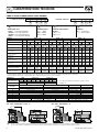 4
4
-
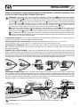 5
5
-
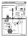 6
6
-
 7
7
-
 8
8
-
 9
9
-
 10
10
-
 11
11
-
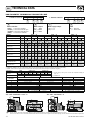 12
12
-
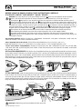 13
13
-
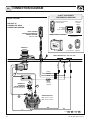 14
14
-
 15
15
-
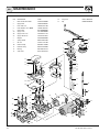 16
16
-
 17
17
-
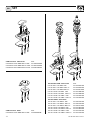 18
18
-
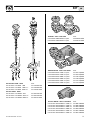 19
19
-
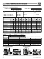 20
20
-
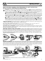 21
21
-
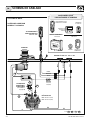 22
22
-
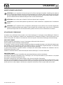 23
23
-
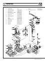 24
24
-
 25
25
-
 26
26
-
 27
27
-
 28
28
-
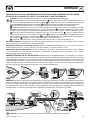 29
29
-
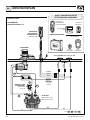 30
30
-
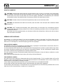 31
31
-
 32
32
-
 33
33
-
 34
34
-
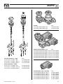 35
35
-
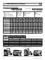 36
36
-
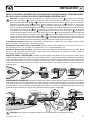 37
37
-
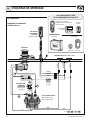 38
38
-
 39
39
-
 40
40
-
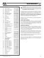 41
41
-
 42
42
-
 43
43
-
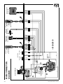 44
44
-
 45
45
-
 46
46
-
 47
47
-
 48
48


en otros idiomas
- français: Quick A 1424 Manuel utilisateur
- italiano: Quick A 1424 Manuale utente
- English: Quick A 1424 User manual
- Deutsch: Quick A 1424 Benutzerhandbuch
Artículos relacionados
-
Quick AL 712 Manual de usuario
-
-
-
-
Quick HC3 1024 DB Manual de usuario
-
-
-
-
-
Quick HRC 1002 Manual de usuario