
Manuale d'uso SALPA ANCORA ORIZZONTALI
User's Manual HORIZONTAL WINDLASSES
Manuel de l'utilisateur GUINDEAUX HORIZONTAL
Benutzerhandbuch HORIZONTAL ANKERWINDEN
Manual del usuario MOLINETES HORIZONTALES
GP2 GENIUS SERIES
1500/2000
GP2 1500
GP2 1500 D
GP2 1500 F
GP2 2000
GP2 2000 D
GP2 2000 F
REV 001a
High
Quality
Nautical
Equipment
CIMA E CATENA SU UN UNICO BARBOTIN
ROPE AND CHAIN ON A SINGLE GYPSY
CORDAGE ET CHÂINE SUR LE MÊME BARBOTIN
KETTE AUF EINER KOMBINIERTEN KETTENNUSS
CABO Y CADENA EN UN ÚNICO BARBOTEN
IT
GB
FR
DE
ES


GP2 SERIES GENIUS 1500/2000 - REV001A
3
Pag. 4 Caratteristiche tecniche
Pag. 5 Installazione
Pag. 6 Schema di collegamento
Pag. 7 Uso - Avvertenze importanti
Pag. 8/9 Manutenzione - GP2
Pag. 10 Uso - GP2 Free Fall
Pag. 11 Manutenzione - GP2 Free Fall
Pag. 12/13 Set
Pag. 14 Technical data
Pag. 15 Installation
Pag. 16 Connection diagram
Pag. 17 Usage - warning
Pag. 18/19 Maintenance - GP2
Pag. 20 Usage - GP2 Free Fall
Pag. 21 Maintenance - GP2 Free Fall
Pag. 22/23 Set
Pag. 24 Caractéristiques techniques
Pag. 25 Installation
Pag. 26 Schema de cablage
Pag. 27 Utilisation - Avvertissements importants
Pag. 28/29 Entretien - GP2
Pag. 30 Utilisation - GP2 Free Fall
Pag. 31 Entretien - GP2 Free Fal
Pag. 32/33 Groupes
Seite 34 Technische Eigenschaften
Seite 35 Montage
Seite 36 Anschlussplan
Seite 37 Gebrauch - Wichtige hinweise
Seite 38/39 Wartung - GP2
Seite 40 Gebrauch - GP2 Free Fall
Seite 41 Wartung - GP2 Free Fall
Seite 42/43 Gruppen
Pág. 44 Características técnicas
Pág. 45 Instalación
Pág. 46 Esquema de montage
Pág. 47 Uso - Advertencias importantes
Pág. 48/49 Mantenimiento - GP2
Pág. 50 Uso - GP2 Free Fall
Pág. 51 Mantenimiento - GP2 Free Fall
Pág. 52/53 Grupos
INDICE
INDEX
SOMMAIRE
INHALTSANGABE
INDICE
IT
GB
FR
DE
ES

4
CARATTERISTICHE TECNICHE
IT
GP2 SERIES GENIUS 1500/2000 - REV001A
DIMENSIONI DEI MODELLI mm ( inch )
249 (9
25
/32)
135 (5
5
/16) 217 (7
31
/32)
249 (9
25
/32)
135 (5
5
/16) 217 (7
31
/32)
GP2 1500 FF - GP2 2000 FFGP2 1500 / D - GP2 2000 / D
(1) Dopo un primo periodo d’uso.
(2) Misure effettuate con barbotin per catena da 8 mm.
(3) Valore minimo consigliato per una lunghezza totale L<20m (Vedi pag. 6).
Calcolare la sezione del cavo in funzione della lunghezza del collegamento.
(4) Con interruttore specifico per correnti continue (DC) e ritardato (magneto-termico o magneto-idraulico).
(5) Su richiesta possono essere forniti prigionieri per spessori di coperta maggiori.
(*) I valori in tabella si riferiscono ad una cima in poliestere a 3 legnoli con la giunzione cima/catena secondo il sistema “Quick
®
”.
(**) ISO EN 818-3.
Quick
®
si riserva il diritto di apportare modifiche alle caratteristiche tecniche dell'apparecchio e al contenuto di questo manuale senza alcun preavviso.
In caso di discordanze o eventuali errori tra il testo tradotto e quello originario in italiano, fare riferimento al testo italiano o inglese.
F
MODELLO GP2 1500 / D - GP2 1500 FF GP2 2000 / D - GP2 2000 FF
POTENZA MOTORE 500W 800W
Tensione motore 12V 12V 24V
Tiro istantaneo massimo 680 Kg (1499,0 lb) 900 Kg (1984 lb) 900 Kg (1984 lb)
Carico di lavoro massimo 250 Kg (551,0 lb) 350 Kg (772,0 lb) 350 Kg (772,0 lb)
Carico di lavoro 85 Kg (187,0 lb) 120 kg (265,0 lb) 120 kg (265,0 lb)
Assorbimento corrente al carico di lavoro (1) 76 A 96 A 50 A
Velocità massima di recupero (2) 25,5 mm (83,7 ft/min) 29,6 mm (97,1 ft/min) 29,6 mm (97,1 ft/min)
Velocità di recupero al carico di lavoro (2) 10,3 mm (33,8 ft/min) 20,0 mm (65,6 ft/min) 20,1 mm (65,9 ft/min)
Sezione minima cavi motore (3) 10 mm
2
(AWG7) 16 mm
2
(AWG5) 10 mm
2
(AWG7)
Interruttore di protezione (4) 40 A 80 A 40 A
Spessore coperta (5) 20 ÷ 40 mm (3/4” ÷ 1” 9/16)
Peso - modello senza campana 10,2 kg (22,4 lb)
Peso - modello con campana 11,5 kg (25,3 lb)
Peso - modello Free Fall 10,9 kg (24,0 lb)
BARBOTIN 6 mm 7 mm - 1/4” 8 mm 5/16”
Catena supportata
6 mm 6 mm 7 mm 7 mm 1/4” 1/4” 8 mm 8 mm 5/16”
DIN 766 ISO** DIN 766 ISO** G4 BBB DIN 766 ISO** G4
Cima supportata * 1/2” (12,7 mm) 1/2” (12,7 mm) 1/2” (12,7 mm) 1/2” (12,7 mm) 1/2” (12,7 mm)

5
INSTALLAZIONE
IT
GP2 SERIES GENIUS 1500/2000 - REV001A
ATTENZIONE:
prima di effettuare il collegamento accertarsi che non sia presente l'alimentazione su cavi.
PRIMA DI UTILIZZARE IL SALPA ANCORA LEGGERE ATTENTAMENTE IL PRESENTE MANUALE D'USO.
IN CASO DI DUBBI CONSULTARE IL RIVENDITORE QUICK
®
.
ATTENZIONE:
i salpa ancora Quick
®
sono stati progettati e realizzati per salpare l'ancora. Non utilizzare questi apparecchi
per altri tipi di operazioni.
Quick
®
non si assume alcuna responsabilità per i danni diretti o indiretti causati da un uso impro-
prio dell'apparecchio. Il salpa ancora non è progettato per sostenere carichi generati in particolari condizioni atmosferiche
(burrasca).
Disattivare sempre il salpa ancora quando non è in uso. Accertarsi che non vi siano bagnanti nelle vicinanze
prima di calare l’ancora.
La giunzione tra la cima e la catena deve avere dimensioni ridotte per poter scorrere agevolmente
dentro la sagoma del barbotin. Per qualsiasi problema o richiesta contattare l’assistenza Quick
®
. Per maggiore sicurezza, nel
caso in cui uno si danneggi suggeriamo di installare almeno due comandi per l’azionamento del salpa ancora.
Consigliamo l’uso dell’interruttore magneto-idraulico Quick
®
come sicurezza per il motore. Bloccare la catena con un
fermo prima di partire per la navigazione.
La scatola teleruttori o teleinvertitori deve essere installata in un luogo protetto da
possibili entrate d’acqua.
Dopo aver completato l’ancoraggio, fissare la catena o cima a punti fissi quali chian stopper o bitta.
Per prevenire rilasci non voluti l’ancora deve essere fissata, il salpa ancora non deve essere usato come unica presa di forza.
Isolare il salpa ancora dall’impianto elettrico durante la navigazione (disinserire l’interruttore di protezione del motore) e bloc-
care la catena ad un punto fisso dell’imbarcazione.
LA CONFEZIONE CONTIENE:
salpa ancora - cassetta teleinvertitori - guarnizione della base - dima di foratura - leva - viterie (per
l'assemblaggio) - manuale d’uso - condizioni di garanzia.
ATTREZZI NECESSARI PER L'INSTALLAZIONE:
trapano con punte: Ø 9 mm (23/64") e Ø 11mm (7/16”); a tazza Ø 40 mm (1" 9/16);
chiave esagonale: 13 mm.
ACCESSORI QUICK
®
CONSIGLIATI:
deviatore da pannello (mod. 800) - Pulsantiera stagna (mod. HRC1002) - Pulsante a piede (mod.
900) - Interruttore magneto-idraulico - Conta catena per l'ancoraggio (mod. CHC 1102M e CHC 1202M) - Sistema di comando via radio
RRC (mod. R02, P02, H02).
REQUISITI PER L'INSTALLAZIONE:
il salpa ancora va posizionato allineando il barbotin con il puntale di prua. Verificare che le
superfici superiore e inferiore della coperta siano più parallele possibili; se ciò non dovesse accadere compensare opportunamente la
differenza (la mancanza di parallelismo potrebbe causare perdite di potenza del motore). Lo spessore di coperta dovrà essere compreso
fra i valori indicati in tabella. Se si avessero spessori differenti è necessario consultare il rivenditore Quick
®
. Non devono esistere ostacoli
sotto coperta per il passaggio di cavi, cima e catena, la poca profondità del gavone potrebbe provocare inceppamenti.
PROCEDURA DI MONTAGGIO:
stabilita la posizione ideale praticare i fori utilizzando la dima di foratura fornita a corredo. Rimuo-
vere il materiale in eccesso dal foro di passaggio della catena/cima, rifinirlo e lisciarlo con un prodotto specifico (vernice marittima, gel
o resina epossidica) assicurando il libero passaggio della catena/cima. Posizionare il salpa ancora calandolo da sopra coperta. Avvitare
i prigionieri, utilizzando il lato corto, sulla base. Fissare il salpa ancora avvitando i dadi sui prigionieri di bloccaggio. Collegare i cavi di
alimentazione provenienti dal salpa ancora al teleinvertitore.
MAX 5 MM
(3/16”)
40 CM
(16”)
45°

6
IT
GP2 SERIES GENIUS 1500/2000 - REV001A
-
+
M1 M2
PULSANTIERA
MULTIUSO
MOD. HRC 1002
SALPA ANCORA
BATTERIA
INTERRUTTORE
MAGNETO
IDRAULICO
(VEDI TABELLA
PAG. 4)
CASSETTA
TELEINVERTITORI
MOD. T6415-12 (12V)
MOD. T6415-24 (24V)
C
A2
PULSANTI A PIEDE MOD. 900U E 900D
NERO
MARRONE
BLU
MARRONE
NERO
BLU
A1
FUSIBILE
4A (12V)
2A (24V)
SISTEMA BASE
CONTACATENA
DA PANNELLO
COMANDO
DA PLANCIA
PULSANTIERA
CONTACATENA
ACCESSORI QUICK
®
PER L'AZIONAMENTO
DEL SALPA ANCORA
L = L1 + L2 + L3 + L4 + L5
L3L2
L1
L4
L5
SCHEMA DI COLLEGAMENTO
TASCABILE - PULSANTIERA
RICEVITORE TRASMETTITORI
RADIOCOMANDI

7
IT
GP2 SERIES GENIUS 1500/2000 - REV001A
ATTENZIONE:
non avvicinare parti del corpo o oggetti alla zona in cui scorrono catena, cima e barbotin. Accer-
tarsi che non sia presente l’alimentazione al motore elettrico quando si opera manualmente sul salpa ancora
(anche quando si utilizza la leva per allentare la frizione); infatti persone dotate di comando a distanza del salpa
ancora (pulsantiera remota o radiocomando) potrebbero accidentalmente attivarlo.
ATTENZIONE:
bloccare la catena con un fermo prima di partire per la navigazione.
ATTENZIONE:
non attivare elettricamente il salpa ancora con la leva inserita nella campana o nel coperchio del
barbotin.
ATTENZIONE:
Quick
®
consiglia di utilizzare un interruttore specifico per correnti continue (DC) e ritardato
(magneto termico o magneto idraulico) per proteggere la linea del motore da surriscaldamenti o corto-circuiti.
L’interruttore può essere utilizzato per isolare il circuito di comando del salpa ancora evitando così azionamenti
accidentali.
USO DELLA FRIZIONE
MOD. FF
(vedi tavola pag. 11)
Il barbotin è reso solidale all’albero principale (
A
) dalla frizione (
F
). La frizione si apre (stacco) utilizzando la leva (37) che
inserita nel coperchio barbotin (
F
) dovrà ruotare in senso antiorario. Ruotando in senso orario si provocherà la chiusura
(attacco) della frizione.
MOD. 1500/2000
(vedi tavola pag. 8-9)
Il barbotin è reso solidale all’albero principale (28 o 46) dalla frizione (34). La frizione si apre (stacco) utilizzando la leva
(37) che inserita nella bussola (49) della campana o nel coperchio barbotin (36) dovrà ruotare in senso antiorario. Ruo-
tando in senso orario si provocherà la chiusura (attacco) della frizione.
PER SALPARE
Accendere il motore dell’imbarcazione. Assicurarsi che la frizione sia serrata ed estrarre la leva. Premere il pulsante UP
del comando a vostra disposizione. Se il salpa ancora si arresta senza che l’interruttore magneto-idraulico (o magneto-
termico) sia scattato, attendere qualche secondo e riprovare (evitare una pressione continuata del pulsante). Se l’inter-
ruttore magneto-idraulico (o magnetotermico) è scattato, riattivare l’interruttore e attendere qualche minuto prima di
riprendere a salpare. Se, dopo ripetuti tentativi, il salpa ancora continua a bloccarsi consigliamo di manovrare l’imbarca-
zione per disincagliare l’ancora.
Controllare la salita degli ultimi metri di catena per evitare danni alla prua.
PER CALARE
La calata dell’ancora si può effettuare tramite comandi elettrici oppure manualmente. Per effettuare l’operazione ma-
nualmente occorre aprire la frizione lasciando libero il barbotin di girare sul proprio asse e trascinare la catena o la cima
in acqua. Per frenare la caduta dell’ancora bisogna ruotare la leva in senso orario. Per calare l’ancora elettricamente
occorre premere il pulsante DOWN del comando a vostra disposizione. In questo modo la calata è perfettamente con-
trollabile e lo svolgimento della catena è regolare. Per evitare sollecitazioni sul salpa ancora, una volta ancorati, bloccare
la catena con un fermo oppure fissarla ad un punto saldo con una cima.
USO DELLA CAMPANA
MOD.1500 D / 2000 D (vedi tavola pag. 8-9)
ATTENZIONE:
prima di eseguire operazioni di tonneggio, accertarsi che l’ancora e relativa cima o catena siano
fissate saldamente ad una bitta o ad altro punto resistente dell’imbarcazione.
Per l’uso indipendente della campana (48) aprire la frizione con la leva (37), (almeno 2 giri della bussola in senso
antiorario). Rimuovere la leva dalla bussola (49), avvolgere la cima sulla campana (almeno 3 giri). Attivare il comando
del salpa ancora mantenendo in tensione la cima durante il recupero. Variando questa tensione in fase di recupero è
possibile modificare la velocità di avvolgimento della cima.
ATTENZIONE:
durante il recupero, mantenere un’adeguata distanza di sicurezza tra mani e campana salpa
ancora.
Terminata la procedura di recupero serrare la frizione stringendo la bussola del barbotin in senso orario e assicurare la
cima ad una bitta o ad altro punto resistente dell’imbarcazione.
USO - AVVERTENZE IMPORTANTI

8
IT
GP2 SERIES GENIUS 1500/2000 - REV001A
3
22
17
50
45
23
17
53
24
25
24
30
15
46
47
3
26
28
21
18
20
19
27
18
27
27
10
9
7
8
7
1
43
12
11
3
5
6
5
4
3
2
52
13
51
38
39
40
41
42
14
48
44
32
31
35
34
34
49
36
51
33
29
16
37
GP2 1500
GP2 1500 D
GP2 2000
GP2 2000 D
POS. DENOMINAZIONE
1A Motore 800W 12V
1B Motore 800W 24V
1C Motore 500W 12V
2 Ruota solare
3 Spina
4 Corona fissa
5 Vite
6 Anello ø 80
7 Ralla
8 Gruppo planetario
9 Corona mobile
10 Cuscinetto
11 Anello elastico
12 Chiavetta
MANUTENZIONE

9
IT
GP2 SERIES GENIUS 1500/2000 - REV001A
ATTENZIONE:
accertarsi che non sia presente l’alimen-
tazione al motore elettrico quando si opera manualmen-
te sul salpa ancora; rimuovere con cura la catena dal
barbotin.
I salpa ancora Quick
®
sono costituiti da materiali resistenti
all’ambiente marino: è indispensabile, in ogni caso, rimuovere
periodicamente i depositi di sale che si formano sulle superfici
esterne per evitare corrosioni e di conseguenza danni all’ap-
parecchio.
Lavare accuratamente con acqua dolce le superfici e le parti in
cui il sale può depositarsi.
Smontare una volta all’anno il barbotin attenendosi alla
seguente sequenza:
VERSIONE CON SISTEMA AUTOMATICO
DI CADUTA LIBERA
Con la leva (37) svitare il coperchio barbotin (
F
); svitare la vite
(
H
) ed estrarre il coperchio barbotin.
Svitare le viti di fissaggio (33) dello stacca catena (32) e rimuo-
verlo; estrarre il barbotin (35).
VERSIONE SENZA CAMPANA
Con la leva (37) svitare il coperchio barbotin (36); estrarre il cono
frizione superiore (34); svitare le viti di fissaggio (33) dello stacca
catena (32) e rimuoverlo; estrarre il barbotin (35).
VERSIONE CON CAMPANA
Con la leva (37) svitare la bussola (49); estrarre la campana (48)
ed il cono frizione superiore (34); svitare le viti di fissaggio (33)
dello stacca catena (32) e rimuoverlo; estrarre il barbotin (35).
Pulire ogni parte smontata affinché non si verifichino attacchi
di corrosione e ingrassare (con grasso marino) il filetto dell’al-
bero (28, 46 o
A
) e il barbotin (35) dove appoggiano i coni
frizione (34).
Rimuovere eventuali depositi di ossido sui morsetti della cas-
setta teleinvertitori; cospargerli di grasso.
POS.
DENOMINAZIONE
13 Vite
14 Leva tendicima
15 Molla tendicima
16 Vite tendicima
17 Spina
18 Rondella
19 Ruota oziosa
20 Cuscinetto
21 Spina
22 Vite
23 Base salpa
24 Cuscinetto
25 Anello elastico
26 Ruota uscita
27 Spina
28 Albero corto
29 Paraolio
30 Coperchio salpa
31 Sensore reed assemblato
32 Stacca catena
33 Vite
34 Cono frizione salpa
35A Barbotin “GP2”
35B Barbotin “GP2” 7 mm - 1/4”
35C Barbotin “GP2” 8 mm
35D Barbotin “GP2” 5/16”
36 Coperchio barbotin
37 Leva salpa nylon
38 Guarnizione/dima
39 Prigioniero
40 Rondella
41 Rondella dentellata
42 Dado
43 Cavo
44 Vite
45 Guarnizione carter
46 Albero lungo
47 Chiavetta
48 Campana
49 Bussola
50 Spina
51 Grower
52 Spina
53 Passacavo
MANUTENZIONE

10
IT
GP2 SERIES GENIUS 1500/2000 - REV001A
SISTEMA AUTOMATICO DI CADUTA LIBERA MOD. GP2 1500 FF - MOD. GP2 2000 FF
ATTENZIONE:
L’attivazione o disattivazione del sistema automatico deve essere effettuata con la frizione chiusa
(attaccata) onde evitare possibili malfunzionamenti degli organi elettromeccanici.
ATTIVAZIONE SISTEMA AUTOMATICO DI CADUTA LIBERA
Con questa procedura si attiva il sistema automatico di caduta libera.
• Ruotare il coperchio
F
fino ad avere il foro di uscita del perno
D
orientato
verso l’alto (come fig.A).
• Togliere l’ alimentazione del salpa ancora.
• Bloccare la catena con un fermo.
• Tirare il pomello
G
fino alla completa fuoriuscita del perno
D
.
• Assicurarsi che la frizione sia chiusa (attaccata).
• Sbloccare la catena.
• Riattivare l’alimentazione del salpa ancora.
Mantenendo premuto il pulsante DOWN del comando a vostra disposizione, si ottiene l’apertura (stacco) della frizione e
il barbotin gira liberamente rispetto al proprio asse.
Mantenendo premuto il pulsante UP del comando a vostra disposizione, invece, si ottiene la chiusura (attacco) della fri-
zione ed il barbotin torna solidale all’asse “
A
”.
PER CALARE CON SISTEMA AUTOMATICO DI CADUTA LIBERA
Con il sistema automatico attivato, mantenere premuto il pulsante DOWN del comando a vostra disposizione, fino al
punto in cui l’ancora può scendere in caduta libera senza alcun vincolo, quindi rilasciare il pulsante.
Per rallentare o bloccare la caduta catena, mantenere premuto il pulsante UP del comando a vostra disposizione fino ad
ottenere l’effetto voluto.
PER SALPARE CON SISTEMA AUTOMATICO DI CADUTA LIBERA
Eseguire la procedura come descritto nel paragrafo USO - PER SALPARE.
DISATTIVAZIONE SISTEMA AUTOMATICO DI CADUTA LIBERA
Con questa procedura si disattiva il sistema automatico di caduta libera.
• Ruotare il coperchio
F
fino ad avere il foro di uscita del perno
D
orientato
verso l’alto.
• Togliere l’ alimentazione del salpa ancora.
• Bloccare la catena con un fermo.
• Premere il perno
D
, aiutandosi con un adeguato utensile come in fig.B, verso il
centro del barbotin.
• Assicurarsi che la frizione sia chiusa (attaccata).
• Sbloccare la catena.
• Riattivare l’alimentazione del salpa ancora.
Con il sistema automatico di caduta libera disattivato, la catena può essere calata esclusivamente con accompagna-
mento elettrico oppure manualmente (vedi paragrafo USO - USO DELLA FRIZIONE).
FIG.B
FIG.A
G
D
F
USO - GP2 FREE FALL

11
IT
GP2 SERIES GENIUS 1500/2000 - REV001A
3
22
17
50
45
3
23
17
24
25
26
24
21
18
20
19
27
18
10
9
7
8
7
53
1
43
12
11
3
5
6
5
4
2
A
27
52
13
51
38
39
40
41
42
30
16
14
31
15
34
35
37
51
33
M
D
N
C
B
E
H
29
F
I
L
G
32
GP2 1500 FF
GP2 2000 FF
Riferimento numeri alle pagine 8-9
POS. DENOMINAZIONE
A
Albero
B
Guida perno
C
Vite M 8*18
D
Perno Ø 8
E
Molla perno Ø 8
F
Coperchio barbotin
G
Pomello Ø10
H
Vite coperchio barbotin
I
Vite M5
L
Perno Ø 5
M
Molla perno Ø 5
N
Boccola
MANUTENZIONE

12
IT
GP2 SERIES GENIUS 1500/2000 - REV001A
SET
OSP BARBOTIN GP2 8MM FVSSBGP20008A00
OSP BARBOTIN GP2 7MM-1/4” FVSSBGP20714A00
OSP BARBOTIN GP2 6MM FVSSBGP20006A00
OSP BARBOTIN GP2 5/16” FVSSBGP20516A00
OSP KIT TENDICIMA GP2 1500/2000 FVSSTCGP2200A00
OSP COPERCHIO BARBOTIN “SERIE 2” FVSSCPBBASG0A00
OSP CAMPANA SALPA “SERIE 2” INOX FVSSMSE0800XA00
OSP BUSSOLA CAMPANA “SERIE 1-2” FVSSGMSDCP05000

13
IT
GP2 SERIES GENIUS 1500/2000 - REV001A
SET
OSP LEVA SALPA DRITTA NYLON FVSSLVSDN000A00
OSP KIT CONI FRIZIONE GP2 FVSSCFG00000A00
OSP COPERCHIO BARBOTIN “GP2” FF COMPLETO FVSSCPBBGFF0A00
OSP KIT GUIDA PERNO GP2 FF FVSSGPGFF000A00

14
TECHNICAL DATA
GB
GP2 SERIES GENIUS 1500/2000 - REV000A
GB
DIMENSIONS OF MODELS mm ( inch )
(1) After an initial period of use.
(2) Measurements taken with a gypsy for a 8 mm chain.
(3) Minimum allowable value for a total length L< 20m (see pag. 16). Determine the cable size according to the length of the wiring.
(4) With circuit breaker designed for direct currents (DC) and delayed-action (thermal-magnetic or hydraulic-magnetic).
(5) On request, studs can be supplied for greater deck thicknesses.
(*) The values in the table regard a three-strand polyester rope with the “Quick
®
” system rope/chain joint.
(**) ISO EN 818-3.
Quick
®
reserves the right to introduce changes to the equipment and the contents of this manual without prior notice.
In case of discordance or errors in translation between the translated version and the original text in the Italian language, reference will be made to the Italian or English text.
F
MODELS GP2 1500 / D - GP2 1500 FF GP2 2000 / D - GP2 2000 FF
MOTOR OUTPUT 500W 800W
Motor supply voltage 12V 12V 24V
Maximum pull 680 Kg (1499,0 lb) 900 Kg (1984 lb) 900 Kg (1984 lb)
Maximum working load 250 Kg (551,0 lb) 350 Kg (772,0 lb) 350 Kg (772,0 lb)
Working load 85 Kg (187,0 lb) 120 kg (265,0 lb) 120 kg (265,0 lb)
Current absorption @ working load (1) 76 A 96 A 50 A
Maximum chain speed (2) 25,5 mm (83,7 ft/min) 29,6 mm (97,1 ft/min) 29,6 mm (97,1 ft/min)
Maximum chain speed @ working load (2) 10,3 mm (33,8 ft/min) 20,0 mm (65,6 ft/min) 20,1 mm (65,9 ft/min)
Motor cable size (3) 10 mm
2
(AWG7) 16 mm
2
(AWG5) 10 mm
2
(AWG7)
Protection circuit breaker (4) 40 A 80 A 40 A
Deck thickness (5) 20 ÷ 40 mm (3/4” ÷ 1” 9/16)
Weight mod. without drum 10,2 kg (22,4 lb)
Weight mod. with drum 11,5 kg (25,3 lb)
Weight mod. Free Fall 10,9 kg (24,0 lb)
GYPSY 6 mm 7 mm - 1/4” 8 mm 5/16”
Chain size
6 mm 6 mm 7 mm 7 mm 1/4” 1/4” 8 mm 8 mm 5/16”
DIN 766 ISO** DIN 766 ISO** G4 BBB DIN 766 ISO** G4
Rope size * 1/2” (12,7 mm) 1/2” (12,7 mm) 1/2” (12,7 mm) 1/2” (12,7 mm) 1/2” (12,7 mm)
249 (9
25
/32)
135 (5
5
/16) 217 (7
31
/32)
249 (9
25
/32)
135 (5
5
/16) 217 (7
31
/32)
GP2 1500 FF - GP2 2000 FFGP2 1500 / D - GP2 2000 / D

15
INSTALLATION
GB
GP2 SERIES GENIUS 1500/2000 - REV000A
GB
WARNING:
before wiring up, be sure the electrical cables are not live.
BEFORE USING THE WINDLASS READ THESE INSTRUCTIONS CAREFULLY.
IF IN DOUBT, CONTACT YOUR NEAREST “QUICK
®
” DEALER.
WARNING:
the Quick
®
windlasses are designed to weigh the anchor. Do not use the equipment for other purposes.
Quick
®
shall not be held responsible for damage to equipment and/or personal injury, caused by a faulty use
of the equipment.
The windlass is not designed for the loads that might occur in extreme weather conditions (storms).
Always deactivate the windlass when not in use. Check that there are no swimmers nearby before dropping anchor.
The splice between the rope and the chain must be tightly woven for the rope to slide easily into the gypsy shape. For any
problem or request, feel free to contact Quick
®
Technical Service. For improved safety we recommend installing at least
two anchor windlass controls in case one is accidentally damaged.
We recommend the use of the Quick
®
hydraulic-ma-
gnetic switch as the motor safety switch. Secure the chain with a further device before starting the navigation.
The contactor unit or reversing contactor unit must be installed in a point protected from accidental water contact.
After completing the anchorage, secure the chain or rope to fixed points such as chain stopper or bollard.
To prevent accidental releases, the anchor must be secured. The windlass shall not be used as the only securing device.
Isolate the windlass from the power system during navigation (switch the circuit breaker off) and lock the chain securing it to
a fixed point of the boat.
THE PACKAGE CONTAINS:
windlass - reversing contactor unit - base gasket - drill template - handle - bolts and screws (for assem-
bly) - user’s manual - conditions of warranty.
TOOLS REQUIRED FOR INSTALLATION:
drill and drill bits: Ø 9 mm (23/64") and Ø 11 mm (7/16”) - Ø 40 (1” 9/16) hollow mill; hexag-
onal wrenche: 13 mm.
“QUICK
®
”ACCESSORIES RECOMMENDED:
anchoring RL control board (mod. 800) - Waterproof hand helds R/C (mod. HRC 1002) -
Foot switch (mod. 900) - Hydraulic-magnetic circuit breaker - Anchor chain counter (mod. CHC 1102M and CHC1202M) - Radio control
RRC (mod. R02, P02, H02).
INSTALLATION REQUIREMENTS:
the windlass must be positioned with the gypsy aligned with the bow roller. Ensure that the
upper and lower surfaces of the deck are as parallel as possible. If this is not the case, compensate the difference appropriately (a lack
of parallelism could result in a loss of motor power). The deck thickness must be included among the figures listed in the table. In cases
of other thicknesses it is necessary to consult a Quick
®
retailer. There must be no obstacles under deck to the passage of cables, rope
and chain; lack of depth of the peak could cause jamming.
FITTING PROCEDURE:
when the ideal position has been established, drill four holes using the drilling template provided.Remove
excess material from the chain through hole, ensuring the free passage of the chain or rope. Position the windlass lowering it from
above deck and inserting the gasket between the deck and the base. Screw the stud bolts, using the short threaded end, onto the base.
Apply a medium grade locking product onto the thread. Fix the windlass by screwing the nuts onto the fixing studs. Connect the supply
cables from the windlass to the reversing contactor unit.
MAX 5 MM
(3/16”)
40 CM
(16”)
45°

16
GB
GP2 SERIES GENIUS 1500/2000 - REV000A
-
+
M1 M2
MULTI-PURPOSE
WATERTIGHT HAND HELD
REMOTE CONTROL
MOD. HRC 1002
WINDLASS
BATTERY
HYDRAULIC-
MAGNETIC CIRCUIT
BREAKER
(SEE TABLE ON
PAGE 14)
REVERSING
CONTACTOR UNIT
MOD. T6415-12 (12V)
MOD. T6415-24 (24V)
C A2
FOOT SWITCHES MOD. 900U AND 900D
BLACK
BROWN
BLUE
BROWN
BLACK
BLUE
A1
FUSE
4A (12V)
2A (24V)
BASIC SYSTEM
WATERTIGHT
PANEL
CHAIN COUNTER
WINDLASSES
CONTROL
BOARD
WATERTIGHT HAND HELD
CHAIN COUNTER
QUICK
®
ACCESSORIES
FOR WINDLASS OPERATION
REMOTE RADIO CONTROLS
L3L2
L1
L4
L5
L = L1 + L2 + L3 + L4 + L5
CONNECTION DIAGRAM
POCKET
RECEIVERS TRANSMITTERS
HANDHELD

17
GB
GP2 SERIES GENIUS 1500/2000 - REV000A
WARNING:
stay clear of the chains, ropes and gypsy. Make sure the electric motor is off when windlass is used
manually (even when using the handle to disengage the clutch). In fact people with windlass remote controls
(hand-held remote control or radio-controlled systems) might accidentally operate it.
WARNING:
secure the chain with a device before starting the navigation.
WARNING:
do not operate the windlass by using the electrical power when the handle is inserted in the drum or
into the gypsy cover.
WARNING:
Quick
®
recommend using a circuit breaker designed for direct current (DC) with delayed-action
(thermal-magnetic or hydraulic-magnetic) to protect the motor supply line from overheating or short circuits. The
circuit breaker can be used to cut off power to the windlass control circuit and so avoid accidental activation.
CLUTCH USE
MOD. FF
(see drawing on page 21)
The clutch
F
) provides a link between the gypsy and the main shaft (
A
). The clutch can be released (disengagement) by
using the handle (37) which, when inserted into the gypsy cover (
F
), must be turned counter-clockwise. The clutch will
be re-engaged by turning it clockwise.
MOD. 1500/2000
(see drawing on page 18-19)
The clutch (34) provides a link between the gypsy and the main shaft (28 or 46). The clutch can be released (disengage-
ment) by using the handle (37) which, when inserted in the bush (49) of the drum or into the gypsy cover (36), must be
turned counter-clockwise. The clutch will be re-engaged by turning it clockwise.
WEIGHING THE ANCHOR
Turn on the engine. Make sure the clutch is engaged and remove the handle. Press the UP button on the control pro-
vided. If the windlass stops and the hydraulic magnetic switch (or thermal cutout) has not tripped, wait a few seconds
and try again (avoid keeping the button pressed). If the hydraulic magnetic switch, has tripped, reset it and wait a few
minutes before weighing anchor once again. If, after a number of attempts, the windlass is still blocked, we suggest to
move the boat to release the anchor. Check the upward movement of the chain for the last few meters in order to avoid
damages to the bow.
CASTING THE ANCHOR
The anchor can be cast by using the electrical control or manually. To operate manually, the clutch must be disengaged
allowing the gypsy to revolve and letting the rope or chain fall into the water. To slow down the chain, the handle must
be turned clockwise. To cast the anchor by using the electrical power, press the DOWN button on the control provided.
In this manner, anchor casting is under control and the chain and rope unwind evenly. In order to avoid any stress on
the windlass -once the boat is anchored- fasten the chain or secure it in place with a rope.
DRUM USE
MOD.1500 D / 2000 D (see drawing on page 18-19)
WARNING:
before carrying out warping operations, check that the anchor and relative rope or chain are solidly
fixed to a bitt or another strong point on the boat.
For the independent use of the drum (48) release the clutch with the handle (37), (at least 2 turns of the bush anticlock-
wise). Remove the handle from the bush (49) on the gypsy, wrap the rope around the drum (at least 3 turns). Activate
the windlass control, keeping the rope under tension during take up. By varying the tension during take up it is possible
to modify the rope winding speed.
WARNING:
during take up maintain a safe distance between hands and windlass drum.
Once take up is complete, screw up the clutch by tightening the gypsy drum clockwise and secure the rope to a bitt or
other strong point on the boat.
USAGE - WARNING

18
GB
GP2 SERIES GENIUS 1500/2000 - REV000A
MAINTENANCE
3
22
17
50
45
23
17
53
24
25
24
30
15
46
47
3
26
28
21
18
20
19
27
18
27
27
10
9
7
8
7
1
43
12
11
3
5
6
5
4
3
2
52
13
51
38
39
40
41
42
14
48
44
32
31
35
34
34
49
36
51
33
29
16
37
POS. DESCRIPTION
1A Electric motor 800W 12V
1B Electric motor 800W 24V
1C Electric motor 500W 12V
2 Sun gear
3 Plug
4 Fixed gear
5 Screw
6 Ring Ø 80
7 Fifth wheel
8 Plant gear
9 Movable gear
10 Bearing
11 Circlip
12 Key
GP2 1500
GP2 1500 D
GP2 2000
GP2 2000 D

19
GB
GP2 SERIES GENIUS 1500/2000 - REV000A
WARNING:
make sure the electrical power to the motor
is switched off when working manually on the windlass.
Carefully remove the chain from the gypsy.
Quick
®
windlasses are manufactured with materials resistant
to marine environments. In any case, any salt deposits on the
outside must be removed periodically to avoid corrosion and
damage to the equipment. The parts where salt may have built
up should be washed thoroughly with fresh water.
Once a year, the drum and the gypsy are to be taken apart as
follows:
VERSION WITH FREEFALL SYSTEM
Use the handle (37) to unscrew the gypsy cover (
F
); loosen
screw (
H
) and take off the gypsy cover. Loosen the screws (33)
of the chain stripper (32) and remove it; remove the gypsy (35).
NO-DRUM VERSION
Use the handle (37) to remove the gypsy cover (36); remove the
top clutch cone (34); loosen the fixing screws (33) of the chain
stripper (32) and remove it and pull off the gypsy (35).
DRUM VERSION
Use the handle (37) to loosen the bush (49); pull off the drum
(48) and the top clutch cone (34); loosen the fixing screws (33)
of the rope/chain stripper (32) and remove it. Pull off the gypsy
(35).
Clean all the parts removed to avoid corrosion, and grease the
shaft thread (28, 46 or
A
) and the gypsy (35) where the clutch
cones rest (use grease suitable for marine environment) (34).
Remove any oxide deposits from the terminals of the electric
motor and the reversing contactor unit; grease them.
MAINTENANCE
POS.
DESCRIPTION
13 Screw
14 Pressure lever
15 Spring for pressure lever
16 Screw for pressure lever
17 Plug
18 Washer
19 Idler gear
20 Bearing
21 Plug
22 Screw
23 Windlass base
24 Bearing
25 Circlip
26 Output gear
27 Plug
28 Short shaft
29 Oil seal
30 Windlass cover
31 Assembled sensor
32 Rope/chain stripper
33 Screw
34 Windlass clutch
35A Gypsy “GP2”
35B Gypsy “GP2” 7 mm - 1/4”
35C Gypsy “GP2” 8 mm
35D Gypsy “GP2” 5/16”
36 Gypsy cover
37 Windlass lever - Nylon
38 Gasket/jig
39 Stud
40 Washer
41 Spring washer
42 Nut
43 Cable
44 Screw
45 Gasket watertight
46 Gasket watertight
47 Key
48 Drum
49 Bush
50 Plug
51 Grower
52 Plug
53 Cable outlet

20
GB
GP2 SERIES GENIUS 1500/2000 - REV000A
FREEFALL SYSTEM MOD. GP2 1500 FF - MOD. GP2 2000 FF
ATTENTION:
The automatic system should be activated or deactivated with the clutch closed (engaged) to avoid
damage to the electromechanical components.
ACTIVATING THE FREEFALL SYSTEM
Follow the directions given below to activate the freefall system:
• Turn the cover
F
until the pin’s hole
D
faces upwards (as shown in fig.A).
• Shut off power to the windlass.
• Block the chain with a lock.
• Pull the knob
G
until the pin is completely out
D
.
• Make certain the clutch is closed (engaged).
• Release the chain.
• Turn power to the windlass back on.
Hold down the DOWN button to open the clutch (disengaged).
As a result the gypsy will turn freely around its axis.
On the other hand, hold down the UP button to close the clutch (engaged). As a result, the gypsy is integral to the “
A
”
axis again.
CASTING WITH THE FREEFALL SYSTEM
With the freefall system activated, keep the DOWN button pressed up to the point in which the anchor can fall freely
without encountering any problems and then release the button.
To slow down or stop letting the chain fall down, hold down the UP button until the desired effect is obtained.
WEIGHING THE ANCHOR WITH THE FREEFALL SYSTEM
Perform the procedure given in paragraph USAGE - WEIGHING THE ANCHOR.
DEACTIVATING THE FREEFALL SYSTEM
Follow the directions given below to deactivate the freefall system:
• Turn the cover
F
until the pin’s hole
D
faces upwards.
• Shut off power to the windlass.
• Block the chain with a lock.
• Push the pin
D
, into the center of the gypsy with the aid of a suitable tool, as
shown in fig.B.
• Make certain the clutch is closed (engaged).
• Release the chain.
• Turn power to the windlass back on.
When the freefall system is deactivated, the chain can be lowered only electrically or manually (see paragraph USAGE –
CLUTCH USE).
FIG.B
FIG.A
G
D
F
USAGE GP2 FREE FALL

21
GB
GP2 SERIES GENIUS 1500/2000 - REV000A
MAINTENANCE
3
22
17
50
45
3
23
17
24
25
26
24
21
18
20
19
27
18
10
9
7
8
7
53
1
43
12
11
3
5
6
5
4
2
A
27
52
13
51
38
39
40
41
42
30
16
14
31
15
34
35
37
51
33
M
D
N
C
B
E
H
29
F
I
L
G
32
Number and code references given on next page.
POS. DESCRIPTION
A
Shaft
B
Windlass pin guide
C
Screw M 8*18
D
Pin Ø 8
E
Spring pin Ø 8
F
Gypsy cover
G
knob Ø10
H
Gypsy cover screw
I
screw M5
L
Pin Ø 5
M
Spring pin Ø 5
N
Pilot boss
GP2 1500 FF
GP2 2000 FF

22
GB
GP2 SERIES GENIUS 1500/2000 - REV000A
SET
OSP GYPSY GP2 8MM FVSSBGP20008A00
OSP GYPSY GP2 7MM-1/4” FVSSBGP20714A00
OSP GYPSY GP2 6MM FVSSBGP20006A00
OSP GYPSY GP2 5/16” FVSSBGP20516A00
OSP KIT GP2 500/1200 PRESSURE LEVER FVSSTCGP2200A00
OSP GYPSY COVER “SERIES 2” FVSSCPBBASG0A00
OSP WINDLASS DRUM “SERIES 2” STAINLESS S. FVSSMSE0800XA00
OSP DRUM BUSH “SERIES 1-2” FVSSGMSDCP05000

23
GB
GP2 SERIES GENIUS 1500/2000 - REV000A
SET
OSP STRAIGHT WINDLASS LEVER - NYLON FVSSLVSDN000A00
OSP KIT GP2 WINDLASS CLUTCH CONE FVSSCFG00000A00
OSP COMPLET FF “GP2” GYPSY COVER FVSSCPBBGFF0A00
OSP KIT GP2 FF WINDLASS PIN GUIDE FVSSGPGFF000A00

24
CARACTERISTIQUES TECHNIQUES
FR
GP2 SERIES GENIUS 1500/2000 - REV000A
La société Quick
®
se réserve le droit d'apporter les modifications nécessaires aux caractéristiques techniques de l'appareil et au contenu de ce livret sans avis préalable.
En cas de discordances ou d’erreurs éventuelles entre la traduction et le texte original en italien, se référer au texte italien ou anglais.
F
DIMENSIONS DES MODÉLES mm ( inch )
249 (9
25
/32)
135 (5
5
/16) 217 (7
31
/32)
249 (9
25
/32)
135 (5
5
/16) 217 (7
31
/32)
GP2 1500 FF - GP2 2000 FFGP2 1500 / D - GP2 2000 / D
(1) A l’arrêt, après utilisation.
(2) Mesures effectuées avec barbotin pour chaîne de 8 mm.
(3) Valeur minimale conseillée pour une longueur totale L<20m (voir pag. 26).
Déterminer la grandeur du câble réquise selon la longueur de la connexion.
(4) Avec des disjoncteurs conçus pour courants continus (DC) et retardés (magnétique-thermique ou magnétique-hydraulique).
(5) Il peut être fourni, sur demande, des arbres et des prisonniers pour des ponts d’épaisseur plus élevée.
(*) Les valeurs du tableau se réfèrent à un cordage en polyester à trois torons avec l’épaissure cordage/chaîne selon le système “Quick
®
”.
(**) ISO EN 818-3.
MODELE GP2 1500 / D - GP2 1500 FF GP2 2000 / D - GP2 2000 FF
PUISSANCE DU MOTEUR 500W 800W
Tension d'alimentation du moteur 12V 12V 24V
Traction maximum 680 Kg (1499,0 lb) 900 Kg (1984 lb) 900 Kg (1984 lb)
Charge de travail maximale 250 Kg (551,0 lb) 350 Kg (772,0 lb) 350 Kg (772,0 lb)
Charge de travail 85 Kg (187,0 lb) 120 kg (265,0 lb) 120 kg (265,0 lb)
Absorption de courant à la charge de travail (1) 76 A 96 A 50 A
Vitesse maximale de récupération (2) 25,5 mm (83,7 ft/min) 29,6 mm (97,1 ft/min) 29,6 mm (97,1 ft/min)
Vitesse de récupérat. à charge de travail (2) 10,3 mm (33,8 ft/min) 20,0 mm (65,6 ft/min) 20,1 mm (65,9 ft/min)
Section minimale du câble du moteur (3) 10 mm
2
(AWG7) 16 mm
2
(AWG5) 10 mm
2
(AWG7)
Disjoncteur (4) 40 A 80 A 40 A
Epaisseur du pont (5) 20 ÷ 40 mm (3/4” ÷ 1” 9/16)
Poids mod. sans poupée 10,2 kg (22,4 lb)
Poids mod. avec poupée 11,5 kg (25,3 lb)
Poids mod. Free Fall 10,9 kg (24,0 lb)
BARBOTIN 6 mm 7 mm - 1/4” 8 mm 5/16”
Chaîne soutenue
6 mm 6 mm 7 mm 7 mm 1/4” 1/4” 8 mm 8 mm 5/16”
DIN 766 ISO** DIN 766 ISO** G4 BBB DIN 766 ISO** G4
Cordage soutenue * 1/2” (12,7 mm) 1/2” (12,7 mm) 1/2” (12,7 mm) 1/2” (12,7 mm) 1/2” (12,7 mm)

25
INSTALLATION
FR
GP2 SERIES GENIUS 1500/2000 - REV000A
ATTENTION:
avant d’effectuer la connexion, contrôler que les câbles ne soient pas alimentés électriquement.
AVANT D’UTILISER LE GUINDEAU, LIRE ATTENTIVEMENT CE LIVRET D’INSTRUCTIONS.
EN CAS DE DOUTES, S’ADRESSER AU REVENDEUR QUICK
®
.
ATTENTION: les guindeaux Quick
®
ont été concçus et construits pour lever l’ancre. Ne pas utiliser ces appareils pour
effectuer d’autres types d’opérations.
La société Quick
®
n’assume aucune responsabilité pour les dommages directs ou
indirects causés par un mauvais usage de l’appareil.
Le guindeau n’a pas été prévu pour soutenir les charges provoquées
lors de conditions atmosphériques particulières (tempête).
Toujours désactiver le guindeau quand il n’est pas utilisé.
Avant de jeter l’ancre, vérifier qu’il n’y a pas de baigneur à proximité. L’épaissure entre le cordage et la chaîne doit avoir
des dimensions réduites pour pouvoir glisser aisément dans le gabarit du barbotin. Pour tout problème ou toute demande,
contacter l’assistance Quick
®
. Pour une plus grande sécurité, nous suggérons d’installer au moins deux commandes pour
actionner le guindeau au cas où une de celle-ci s’abîmerait.
Fixer la chaîne avec un dispositif d’arrêt avant de partir pour la
navigation.
Nous conseillons l’utilisation de l’interrupteur magnétique-hydraulique Quick
®
comme sécurité pour le moteur.
La boîtier relais ou relais inverseurs doit être installée dans un endroit protégé des éventuelles entrées d’eau. Après avoir
complété l’ancrage, fixer la chaîne ou le filin à des points fixes comme le bloqueur de chaîne ou la bitte.
Afin de prévenir des
relâches accidentels, l’ancre doit être fixée; le guindeau ne doit pas être utilisé comme seule prise de force.
Isoler le guindeau
du système électrique pendant la navigation (débrancher le disjoncteur magnétique) et bloquer la chaîne à un point fixe du bateau.
L’EMBALLAGE COMPREND:
guindeau - boîtier relais inverseur - joint de la base - gabarit de perçage - levier - différentes vis (pour
l’assemblage) - livret d’instructions - conditions de garantie.
OUTILS NECESSAIRES POUR L’INSTALLATION:
perceuse avec mèches: Ø 9 mm (23/64”) et Ø 11 mm (7/16”); à gorge Ø 40 mm
(1”9/16); clé hexagonale: 13 mm.
ACCESSOIRES QUICK
®
RECOMMANDES:
interrupteur sur panneau (mod. 800) - Telecommande étanche (mod. HRC 1002) - Bouton à
pied (mod. 900) - Disjoncteur magnétique-hydraulique - Compteur de chaîne pour l’ancrage (mod. CHC 1102 M et CHC 1202 M - Système
de commande par radio RRC (mod. R02, P02, H02).
CONDITIONS REQUISES POUR L’INSTALLATION:
le guindeau doit être positionné en alignant le barbotin avec le creux de
proue. Contrôler que les surfaces supérieures et inférieures du pont soient les plus parallèles possibles, si ce n’est pas le cas, compen
-
ser la différence de manière opportune (le manque de parallélisme pourrait provoquer des pertes de puissance du moteur). L’épaisseur
du pont devra être comprise parmi les valeurs indiquées dans le tableau. En cas d’épaisseurs différentes, s’adresser au revendeur
Quick
®
. Il ne doit pas y avoir d’obstacles sous le pont pour le passage des câbles, des cordages et des chaînes, le peu de profondeur du
coqueron pourrait provoquer des coincements.
METHODE DE MONTAGE:
une fois que la position idéale est établie, faire les trous en utilisant le gabarit de perçage fourni avec
l’appareil. Enlevez le matériel en excès de l’écubier de puits à chaînes, fignolez et lissez l’ecubier avec un produit spécifique (peinture
marine, enduit gélifié or résine epoxy) en assurant le passage libre du bout et de la chaîne. Positionner la partie supérieure en insérant le
joint entre le pont et la base et relier la partie inférieure à celle-ci en enfilant l’arbre dans le réducteur. Fixer le guindeau avec les écroux
fournis sur les goujons de fixation. Brancher les câbles d’alimentation provenant du guindeau au relais inverseur.
MAX 5 MM
(3/16”)
40 CM
(16”)
45°

26
FR
GP2 SERIES GENIUS 1500/2000 - REV000A
-
+
M1 M2
TELECOMMANDE À
FONCTION MULTIPLE
MOD. HRC 1002
GUINDEAU
BATTERIE
DISJONCTEUR
MAGNÉTIQUE-
HYDRAULIQUE
(VOIR TABLEAU À
LA PAGE 24)
BOÎTIER RELAIS
INVERSEURS
MOD. T6415-12 (12V)
MOD. T6415-24 (24V)
C
A2
BOUTONS À PIED MOD. 900U ET 900D
NOIR
MARRON
BLEU
MARRON
NOIR
BLEU
A1
FUSIBLE
4A (12V)
2A (24V)
COMPTEUR DE
CHAÎNE SUR
TABLEAU
COMMANDE
DU TABLEAU
TELECOMMANDE AVEC
COMPTEUR DE CHAÎNE
MIGNON
RÉCEPTEUR
ACCESSOIRES QUICK
®
POUR ACTIONNER LE GUINDEAU
EMETTEUR
RADIOCOMMANDES
TABLEAU DE
COMMANDE
SYSTEME DE BASE
L3L2
L1
L4
L5
L = L1 + L2 + L3 + L4 + L5
SCHÉMA DE CABLAGE

27
FR
GP2 SERIES GENIUS 1500/2000 - REV000A
27
ATTENTION:
ne pas s'approcher de la zone où glissent la chaîne, le cordage et le barbotin. Contrôler que le mo-
teur ne soit pas alimenté électriquement quand on travaille manuellement sur le guindeau (même quand on uti-
lise le levier pour desserrer l'embrayage); en effet, les personnes munies de commande à distance pour le guin-
deau (tableau des boutons-poussoirs télécommandé ou radiocommandé) pourraient l'activer involontairement.
ATTENTION:
fixer la chaîne avec un dispositif d'arrêt avant de partir pour la navigation.
ATTENTION:
ne pas activer électriquement le guindeau avec le levier introduit dans la cloche ou dans le cou-
vercle du barbotin.
ATTENTION:
Quick
®
conseille d’utiliser un disjoncteur spécifique pour courant continu (DC) et retardé (magné-
to-thermique ou magnéto-hydraulique) pour protéger la ligne du moteur des surchauffes ou des courts-circuits.
Le disjoncteur peut être utilisé pour isoler le circuit de commande du guindeau en évitant ainsi des actionne-
ments accidentels.
UTILISATION DE L'EMBRAYAGE
MOD. FF
(voir dessin à la page 31)
Le barbotin est solidaire de l'arbre principal (
A
) de l'embrayage (
F
). L'embrayage s'ouvre à l'aide du levier (37) qui, une
fois introduit dans le couvercle du barbotin (
F
), devra tourner dans le sens contraire aux aiguilles de la montre. Si l'on
tourne dans le sens des aiguilles d'une montre, l'embrayage se fermera.
MOD. 1500/2000
(voir dessin à la page 28-29)
Le barbotin est solidaire de l’arbre principal (28 ou 46) de l’embrayage (34). L’embrayage s’ouvre à l’aide du levier (37)
qui, une fois introduit dans la douille (49) de la poupée ou dans le couvercle du barbotin (36), devra tourner dans le sens
contraire aux aiguilles de la montre. Si l’on tourne dans le sens des aiguilles d’une montre, l’embrayage se fermera.
POUR LEVER L'ANCRE
Allumer le moteur de l'embarcation. S'assurer si l'embrayage est bien serré et tirer le levier. Presser le bouton UP de
la commande à votre disposition. Si le guindeau s'arrête sans que le disjoncteur magnéto-hydraulique (ou magné-
to-thermique) se soit déclenché, attendre quelques secondes et ré-essayer (éviter de presser le bouton en continu).
Si le disjoncteur magnéto-thermique s'est déclenché, réactiver le disjoncteur et attendre quelques minutes avant de
reprendre l'opération. Si, après plusieurs tentatives, le guindeau continue à se bloquer, nous recommandons d'effectuer
des manoeuvres avec l'embarcation pour désensabler l'ancre. Contrôler la montée des derniers mètres de chaîne pour
éviter des dommages à l'avant de l'embarcation.
POUR JETER L'ANCRE
Il est possible de jeter l'ancre par l'intermédiaire des commandes électriques ou bien manuellement. Pour effectuer
l'opération manuellement, ouvrir l'embrayage en laissant que le barbotin puisse tourner sur son propre axe et traîner
la chaîne ou le cordage dans l'eau. Pour freiner la descente de l'ancre, tourner le levier dans le sens des aiguilles d'une
montre. Pour jeter l'ancre électriquement, presser le bouton DOWN de la commande à votre disposition. De cette ma-
nière-là, la descente peut être bien contrôlée et le déroulement de la chaîne ou du cordage est régulier. Pour éviter tout
effort sur le guindeau, une fois que l'on est ancrés, bloquer la chaîne avec un dispositif d'arrêt ou bien la fixer à un point
solide avec un bout.
UTILISATION DE LA POUPÉE MOD.1500 D / 2000 D
(voir dessin à la page 28-29)
ATTENTION:
Avant d’exécuter les opérations de touage, s’assurer que l’ancre et son cordage ou sa chaîne est
solidement fixée à une bitte ou à un autre point résistant de l’embarcation.
Pour l’utilisation independante de la poupée (48), ouvrir l’embrayage avec le levier (37) (au moins 2 tours de la douille
dans le sens contraire des aiguilles d’une montre). Enlever le levier de la douille (49) sur le barbotin, enrouler le cordage
sur la poupée (au moins 3 tours). Activer la commande du guindeau en maintenant le cordage sous tension pendant le
virage. En chan-geant cette tension en phase de virage, il est possible de modifier la vitesse d’enroulement de la corde.
ATTENTION:
pendant le virage, maintenir une distance de sécurité adéquate entre les mains et la cloche du
guindeau.
Une fois la procedure de virage terminee, serrer l’embrayage en resserant la douille du barbotin dans le sens des
aiguilles d’une montre et assurer la corde a une bitte ou a un autre point resistant de l’embarcation.
UTILISATION

28
FR
GP2 SERIES GENIUS 1500/2000 - REV000A
ENTRETIEN
3
22
17
50
45
23
17
53
24
25
24
30
15
46
47
3
26
28
21
18
20
19
27
18
27
27
10
9
7
8
7
1
43
12
11
3
5
6
5
4
3
2
52
13
51
38
39
40
41
42
14
48
44
32
31
35
34
34
49
36
51
33
29
16
37
POS. DENOMINATION
1A Moteur électrique 800W 12V
1B Moteur électrique 800W 24V
1C Moteur électrique 500W 12V
2 Roue solaire
3 Fiche
4 Couronne fixe
5 Vis
6 Bague ø 80
7 Pièce d’écartement
8 Groupe planétaire
9 Couronne mobile
10 Roulement
11 Circlip
12 Clavette
GP2 1500
GP2 1500 D
GP2 2000
GP2 2000 D

29
FR
GP2 SERIES GENIUS 1500/2000 - REV000A
ATTENTION:
s’assure que le moteur n’est pas alimen-
té électriquement lorsqu’on agit sur le guindeau manuel-
lement. Enlever la chaîne du barbotin.
Les guindeaux Quick
®
sont construits avec des matériaux qui
résistent bien à l’environnement marin: de toute façon, il est
indispensable d’enlever périodiquement les dépôts de sel se
formant sur les surfaces externes pour éviter tout effet de cor-
rosion et des dommages à l’appareil.
Laver les surfaces et les pièces où le sel peut se déposer avec
de l’eau douce.
Une fois par année, démonter le barbotin et la poupée en pro-
cédant dans l’ordre suivant:
VERSION AVEC MECANISME AUTOMATIQUE
A CHUTE LIBRE
Avec le levier (37) dévisser le couvercle du barbotin (
F
); dévisser
la vis (
H
) et retirer le couvercle du barbotin. Dévisser les vis de
fixation (33) du dispositif de détachement de la chaîne (32) et le
retirer; enlever le barbotin (35).
VERSION SANS POUPÉE
A l’aide du levier (37), desserrer le couvercle du barbotin (36);
enlever le cône de l’embrayage supérieur (34); desserrer les vis
de fixation (33) du dispositif qui libère la chaîne (32) et le retirer;
enlever le barbotin (35).
VERSION AVEC POUPÉE
A l’aide du levier (37), desserrer la douille (49); enlever la poupée
(48) et le cône de l’embrayage supérieur (34); desserrer les vis
de fixation (33) du dispositif qui libère la chaîne (32) et le retirer;
enlever le barbotin (35).
Nettoyer chaque pièce qui a été démontée afin d’éviter tout ef-
fet de corrosion et graisser (avec de la graisse marine) le filet de
l’arbre (28, 46 ou
A
) ainsi que le barbotin (35) où les cônes de
l’embrayage appuient (34).
Enlever toutes traces d’oxyde sur les bornes d’alimentation
du moteur électrique et sur celles de la boîtier inverseurs; les
graisser.
ENTRETIEN
POS.
DENOMINATION
13 Vis
14 Levier de pression
15 Ressort pour levier
16 Vis pour levier de pression
17 Fiche
18 Rondelle
19 Roue folle
20 Cuscinetto
21 Fiche
22 Vis
23 Base du guindeau
24 Roulement
25 Circlip
26 Roue de sortie
27 Fiche
28 Arbre court
29 Joint étanche à l’huile
30 Couvercle du guindeau
31 Capteur de la chaîne assemblé
32 Dispositif de détachement
33 Vis
34 Cône de friction
35A Barbotin “GP2”
35B Barbotin “GP2” 7 mm - 1/4”
35C Barbotin “GP2” 8 mm
35D Barbotin “GP2” 5/16”
36 Couvercle du barbotin
37 Levier du guindeau - Nylon
38 Joint / gabarit
39 Goujon
40 Rondelle
41 Grower
42 Écrou
43 Câble
44 Vis
45 Joint carter d’etanchéité
46 Arbre long
47 Clavette
48 Poupée
49 Douille
50 Fiche
51 Grower
52 Fiche
53 Passa-cable

30
FR
GP2 SERIES GENIUS 1500/2000 - REV000A
MECANISME AUTOMATIQUE A CHUTE LIBRE MOD. GP2 1500 FF - MOD. GP2 2000 FF
ATTENTION:
l’activation ou désactivation du système automatique doivent être effectuées avec l'accouplement
à friction fermé (engagé) afin d'éviter de possibles dysfonctionnements des organes électromécaniques.
ENCLENCHEMENT MECANISME AUTOMATIQUE A CHUTE LIBRE
Avec cette procédure on enclenche le mécanisme automatique à chute libre.
• Tourner le couvercle
F
jusqu'à ce que l'orifice de sortie du pivot
D
soit orien-
té vers le haut (comme fig. A).
• Couper l’alimentation du guindeau.
• Bloquer la chaîne avec un arrêt.
• Tirer la poignée
G
jusqu'à ce que le pivot dépasse complètement
D
.
• S'assurer que l'accouplement à friction est bien fermé (engagé).
• Débloquer la chaîne.
• Réactiver l’alimentation du guindeau.
En maintenant la touche DOWN de la commande à votre disposition appuyée, on obtient l’ouverture (désengagé) de
l'accouplement à friction et le barbotin tourne librement par rapport à son axe propre. En maintenant la touche UP de
la commande à votre disposition appuyée, on obtient la fermeture (engagé) de l'accouplement à friction et le barbotin
tourne de manière solidaire à l'axe “
A
”.
POUR JETER L'ANCRE AVEC MECANISME AUTOMATIQUE A CHUTE LIBRE
Avec le mécanisme automatique enclenché, maintenir la touche DOWN de la commande à votre disposition appuyée,
jusqu'au point où l’ancre peut descendre par chute libre sans aucune résistance, puis relâcher la touche.
Pour ralentir ou bloquer la descente de la chaîne, maintenir la touche UP de la commande à votre disposition appuyée
jusqu'à obtenir l'effet désiré.
POUR REMONTER L'ANCRE AVEC MECANISME AUTOMATIQUE A CHUTE LIBRE
Effectuer la procédure comme décrit au paragraphe UTILISATION - POUR JETER L'ANCRE.
DESENCLENCHEMENT MECANISME AUTOMATIQUE A CHUTE LIBRE
Avec cette procédure, on désenclenche le mécanisme automatique à chute libre.
• Tourner le couvercle
F
jusqu'à l'orifice de sortie du pivot
D
soit orienté vers le haut.
• Couper l’alimentation du guindeau.
• Bloquer la chaîne avec un arrêt.
• Appuyer sur le pivot
D
, en s'aidant d'un outil adapté comme indiqué sur la fig.
B, vers le centre du barbotin.
• S'assure que l'accouplement à friction est fermé (engagé).
• Débloquer la chaîne.
• Réactiver l’alimentation du guindeau.
Avec le mécanisme automatique à chute libre désenclenché, la chaîne peut être jetée exclusivement avec un accom-
pagnement électrique ou manuellement (voir paragraphe UTLISATION - UTILISATION DE L'ACCOUPLEMENT A FRICTION).
FIG.B
FIG.A
F
G
D
F
UTILISATION GP2 FREE FALL

31
FR
GP2 SERIES GENIUS 1500/2000 - REV000A
F
ENTRETIEN
3
22
17
50
45
3
23
17
24
25
26
24
21
18
20
19
27
18
10
9
7
8
7
53
1
43
12
11
3
5
6
5
4
2
A
27
52
13
51
38
39
40
41
42
30
16
14
31
15
34
35
37
51
33
M
D
N
C
B
E
H
29
F
I
L
G
32
Référence numéros et codes de la page suivante
POS. DENOMINATION
A
Arbre série
B
Guide pivot
C
Vis M 8*18
D
Pivot Ø 8
E
Ressort pivot Ø 8
F
Couvercle barbotin
G
Poignée Ø10
H
Vis couvercle barbotin
I
Vis M5
L
Pivot Ø 5
M
Ressort pivot Ø 5
N
Douille
GP2 1500 FF
GP2 2000 FF

32
FR
GP2 SERIES GENIUS 1500/2000 - REV000A
GROUPES
OSP BARBOTIN GP2 8MM FVSSBGP20008A00
OSP BARBOTIN GP2 7MM-1/4” FVSSBGP20714A00
OSP BARBOTIN GP2 6MM FVSSBGP20006A00
OSP BARBOTIN GP2 5/16” FVSSBGP20516A00
OSP KIT LEVIER DE PRESSION GP2 500/1200 FVSSTCMG0000A00
OSP COUVERCLE BARBOTIN “SÉRIE 2” FVSSCPBBASG0A00
OSP POUPEE GUINDEAU “SÉRIE 2” INOX FVSSMSE0800XA00
OSP DOUILLE POUPEE “SÉRIE 1-2” FVSSGMSDCP05000

33
FR
GP2 SERIES GENIUS 1500/2000 - REV000A
GROUPES
OSP LEVIER DROIT EN NYLON FVSSLVSDN000A00
OSP KIT CÔNE DE FRICTION GP2 FVSSCFG00000A00
OSP COUVERCLE BARBOTIN “GP2” FF COMPLET FVSSCPBBGFF0A00
OSP KIT GUIDE PIVOT GP2 FF FVSSGPGFF000A00

34
TECHNISCHE EIGENSCHAFTEN
DE
GP2 SERIES GENIUS 1500/2000 - REV000A
Quick
®
behält sich das Recht auf Änderungen der technischen Eigenschaften des Geräts und des Inhalts dieses Handbuchs ohne Vorankündigung vor.
Bei Fehlern oder eventuellen Unstimmigkeiten zwischen der Übersetzung und dem Ausgangstext ist der Ausgangstext in Italienisch oder Englisch maßgeblich.
F
ABMESSUNGEN DER MODELLE
mm ( inch )
249 (9
25
/32)
135 (5
5
/16) 217 (7
31
/32)
249 (9
25
/32)
135 (5
5
/16) 217 (7
31
/32)
GP2 1500 FF - GP2 2000 FFGP2 1500 / D - GP2 2000 / D
(1) Bei gekuppeltem Motor nach der Anlassphase.
(2) Durchgeführte Messungen mit Kettennuss für 8 mm-Kette.
(3) Empfohlener Mindestwert fur eine gesamtmenge lange L<20m (Siehe Abb. 36).
Den Kabelquerschnitt in Abhängigkeit zur Länge des Anschlüsses berechnen.
(4) Mit besonderem Schalter für Gleichstrom (DC) und Verzögerung (Überstrom Schutzautomat oder hydraulischer Schutzautomat).
(5) Auf Anfrage können Gewindestifte für stärker Decks geliefert werden.
(*)
Die Werte in der Tabelle beziehen sich auf ein Tau aus Polyester mit 3 Kardeelen und einer Verbindung Tau/Kette mit dem “Quick
®
”-System.
(**) ISO EN 818-3.
MODELL GP2 1500 / D - GP2 1500 FF GP2 2000 / D - GP2 2000 FF
MOTORLEISTUNG 500W 800W
Spannung Motor 12V 12V 24V
Maximaler Zug 680 Kg (1499,0 lb) 900 Kg (1984 lb) 900 Kg (1984 lb)
Maximaler Arbeitslast 250 Kg (551,0 lb) 350 Kg (772,0 lb) 350 Kg (772,0 lb)
Arbeitslast 85 Kg (187,0 lb) 120 kg (265,0 lb) 120 kg (265,0 lb)
Stromaufnahme bei Arbeitslast (1) 76 A 96 A 50 A
Maximale Rückholgeschwindigkeit (2) 25,5 mm (83,7 ft/min) 29,6 mm (97,1 ft/min) 29,6 mm (97,1 ft/min)
Rückholgeschwindigkeit bei Arbeitslast (2) 10,3 mm (33,8 ft/min) 20,0 mm (65,6 ft/min) 20,1 mm (65,9 ft/min)
Motorkabel-Mindestquerschnitt (3) 10 mm
2
(AWG7) 16 mm
2
(AWG5) 10 mm
2
(AWG7)
Schutzschalter (4) 40 A 80 A 40 A
Stärke des Decks (5) 20 ÷ 40 mm (3/4” ÷ 1” 9/16)
Gewicht mod. ohne Verholspill 10,2 kg (22,4 lb)
Gewicht mod. mit Verholspill 11,5 kg (25,3 lb)
Gewicht mod. Free Fal 10,9 kg (24,0 lb)
KETTENNUSS 6 mm 7 mm - 1/4” 8 mm 5/16”
Kettengröße
6 mm 6 mm 7 mm 7 mm 1/4” 1/4” 8 mm 8 mm 5/16”
DIN 766 ISO** DIN 766 ISO** G4 BBB DIN 766 ISO** G4
Taugröße * 1/2” (12,7 mm) 1/2” (12,7 mm) 1/2” (12,7 mm) 1/2” (12,7 mm) 1/2” (12,7 mm)

35
MONTAGE
DE
GP2 SERIES GENIUS 1500/2000 - REV000A
ACHTUNG:
vor Durchführung des Anschlusses sicherstellen, daß an den Kabeln keine Spannung anliegt.
VOR DEM GEBRAUCH DER ANKERWINDE DIESE BETRIEBSANLEITUNG AUFMERKSAM DURCHLESEN.
IM ZWEIFELSFALL WENDEN SIE SICH BITTE AN DEN QUICK
®
-VERTRAGSHÄNDLER.
ACHTUNG:
die Quick
®
-Ankerwinden wurden eigens für das Fieren der Anker entwickelt und hergestellt. Diese Vorrichtungen
für keine anderen Zwecke verwenden.
Quick
®
haftet nicht für direkte oder indirekte Schäden, die durch einen unsachgemäßen
Gebrauch des Geräts entstehen.
Die Ankerwinde ist nicht darauf ausgelegt, Belastungen unter besonderen Wetterbedingungen
(Sturm) standzuhaten.
Die Ankerwinde immer ausschalten, wenn sie nicht benützt wird. Vor dem Herunterlassen vom Anker
muss sicher-gestellt werden, dass sich keine Badenden in der Nähe aufhalten.
Die Verbindung zwischen Tau und Kette muss so
klein wie möglich sein, um leicht durch die Führung in der Kettennuss zu laufen. Bei Problemen oder Fragen wenden Sie sich bitte
an den Quick
®
Kundendienst. Um für mehr Sicherheit zu garantieren, sollten mindestens zwei Steuerungen für die Ankerwin-
de instal-liert werden für den Fall, dass Defekte an einer der Steuerungen auftreten. Die Kette mit einer Feststellvorrichtung
blockieren, bevor man mit dem Boot ausfährt.
Es wird zur Verwendung eines Hauptsi-cherungsautomaten Quick
®
zur Motor-
sicherung geraten. Die Dose mit den Relaisbox oder den Umpolrelaisbox muss an einem vor Wasser geschützten Ort installiert
werden.
Nachdem Sie geankert haben, Kette/Seil immer über Kettenstopper bzw. Poller fest halten.
Ankerwinde darf nie als einzelnen Festpunkt für Ihren Boot dienen.
Schalten Sie immer die Winde am Sicherungsautomat (oder Trennschalter) aus, wenn sie nicht Gebrauch ist.
DIE PACKUNG ENTHÄLT:
Ankerwinde - Umpolrelaisbox - Basisdichtung - Bohrschablone - Hebel - Schrauben (für den Zusammenbau)
- Betriebsanleitung - Garantiebedinungen.
NOTWENDIGE WERKZEUGE FÜR DIE INSTALLATION:
Bohrmaschine Bohrer: Ø 9 mm (23/64”) und Ø 11 mm (7/16"); Scheibe Ø 40
mm (1"9/16); Inbusschlüssel: 13 mm.
EMPFOHLENE QUICK
®
-ZUBEHÖRTEILE:
Schalter an Bedientafel (mod. 800) - Wasserdichte Fernbedienung (mod. HRC 1002) - Fuß-
schalter (mod. 900) - hydraulischer Schutzautomat - Ketten zähler für Verankerung (mod. CHC1102M und CHC 1202M) - Funksteuersy-
stem RRC (mod. R02, P02, H02).
VORAUSSETZUNGEN FÜR DIE INSTALLATION:
Die Ankerwinde muss so positioniert werden, dass die Kettennuss mit der Bugs-
tütze ausgerichtet ist. Sicherstellen, dass Oberseite und Unterseite vom Deck so parallel wie möglich verlaufen. Falls nicht, die Differenz auf
geeignete Weise ausgleichen, da es sonst zu Leistungsverlust am Motor kommen kann. Die Dicke vom Deck muss innerhalb der in der Ta
-
belle angegebenen Wertspannen liegen. Sollte die Dicke nicht mit den angegebenen Werten übereinstimmen, muss mit dem Quick
®
-Händ-
ler Rücksprache gehalten werden. Unter Deck darf es keine Hindernisse geben, die das Durchführen von Kabeln, Tau und Kette behindern.
Eine zu geringe Tiefe vom Kabelgatt kann dazu führen, dass sich die Kabel verklemmen.
MONTAGE:
Nachdem die ideale Position ermittelt worden ist, mithilfe der mitgelieferten Schablone die erforderlichen Löcher bohren.
Das Durchgangsloch für die Kette von Materialresten befreien und sicherstellen, dass die Kette oder das Tau unbehindert durch das Loch
läuft. Die Ankerwinde positionieren und dazu vom Deck herablassen. Dabei die Dichtung zwischen Deck und Basis einsetzen. Den Spren
-
gring mit der kurzen Gewindeseite auf die Basis aufschrauben. Auf das Gewinde ein mittelstarkes Bremsmittel auftragen. Die Ankerwin-
de mit den mitgelieferten Schraubenmuttern an den Sprengringen befestigen. Die Stromkabel der Ankerwinde an den Umpolrelaisbox
anschließen.
MAX 5 MM
(3/16”)
40 CM
(16”)
45°

36
DE
GP2 SERIES GENIUS 1500/2000 - REV000A
-
+
M1 M2
MEHRZWECK-
WASSERDICHTE
FERNBEDIENUNG
MOD. HRC 1002
ANKERWINDE
BATTERIE
HYDRAULISCHER
SHUTZAUTOMAT
(SIEHE TABELLE
AUF S. 34)
UMPOLRELAISBOX
MOD. T6415-12 (12V)
MOD. T6415-24 (24V)
C
A2
FUSSSCHALTER MOD. 900U UND 900D
SCHWARZ
BROWN
BLAU
BROWN
SCHWARZ
BLAU
A1
SICHERUNG
4A (12V)
2A (24V)
KETTENZÄHLER-
TAFEL
SCHALTER AN
BEDIENTAFEL
METERZÄHLER-
FERNBEDIENUNG
FÜR DIE ANKERWINDE
TASCHEN - DRUCKKNOPFSTAFEL
EMPFANGSGERÄT
QUICK
®
-ZUBEHÖRTEILE FÜR DIE
BETÄTIGUNG DER ANKERWINDE
FUNKFERNSENDER
FUNKFERNSTEUERUNG
BASISSYSTEM
L3L2
L1
L4
L5
L = L1 + L2 + L3 + L4 + L5
ANSCHLUSSPLAN

37
DE
GP2 SERIES GENIUS 1500/2000 - REV000A
ACHTUNG: Körperteile oder Gegenstände fern von den Bereichen halten, in denen sich die Kette, Leine und die
Kettennuss bewegen. Sicherstellen, daß der elektrische Motor nicht an Spannung liegt, wenn man manuell an der
Ankerwinde eingreift (auch dann, wenn man den Hebel zum Lösen der Kupplung verwendet): mit Fernbedienung
der Ankerwinde ausgestattete Personen (Fernbedienfeld oder Funksteuerung) könnten die Ankerwinde einschalten.
ACHTUNG:
Die Kette mit einer Feststellvorrichtung blockieren, bevor man mit dem Boot ausfährt.
ACHTUNG:
Die Ankerwinde nicht elektrisch einschalten, wenn der Hebel in der Verholspill oder im Kettennuss-
deckel eingesetzt ist.
ACHTUNG:
Quick
®
empfiehlt die Verwendung eines Spezialschalters für Gleichstrom (DC) mit Verzögerung
(Wärmeschutzschalter oder Hauptsicherungsautomat) zum Schutz der Stromleitung vom Motor und zum Schutz
gegen Überhitzung oder Kurzschlüsse. Der Schalter kann dazu verwendet werden, um den Steuerschaltkreis der
Ankerwinde zu isolieren und so ein versehentliches Einschalten zu verhindern.
GEBRAUCH DER KUPPLUNG
MOD. FF
(siehe Zeichnung auf seite 41)
Die Kettennuss ist über die Kupplung (
A
) fest mit der Hauptwelle (
A
) verbunden. Zum Öffnen (Lösen) der Kupplung dreht
man den Hebel (37) in der Kettennussdeckel (
F
) gegen den Uhrzeigersinn. Dreht man ihn im Uhrzeigersinn, so wird die
Kupplung geschlossen (angezogen).
MOD. 1500/2000
(siehe Zeichnung auf seite 38-39)
Die Kettennuss ist über die Kupplung (34) fest mit der Hauptwelle (28 oder 46) verbunden. Zum Öffnen (Lösen) der Kup-
plung dreht man den Hebel (37) in der Buchse (49) der Verholspill oder der Kettennussdeckel (36) gegen den Uhrzeiger-
sinn. Dreht man ihn im Uhrzeigersinn, so wird die Kupplung geschlossen (angezogen).
ZUM LICHTEN DES ANKERS
Den Bootmotor einschalten. Sich vergewissern, daß die Kupplung angezogen ist und den Hebel herausziehen. Die UP-Ta-
ste an der Ihnen zur Verfügung stehenden Bedientafel drücken.
Falls die Ankerwinde anhält, ohne daß der Schutzautomat (oder thermomagnetische Schalter) ausgelöst wurde, einige
Sekunden warten und nochmals probieren (die Taste sollte nicht lange gedrückt werden). Falls der Schutzautomat aus-
gelöst wurde, den Schalter rückstellen und einige Minuten vor Lichten des Ankers warten. Falls nach mehreren Versu-
chen die Ankerwinde weiter blockiert wird, empfehlen wir Ihnen das Boot zu manövrieren, um den Anker freizumachen.
Beim lichten der letzten Kettenmeter darauf achten, daß der Bug nicht beschädigt wird.
ZUM SENKEN DES ANKERS
Der Anker kann mit den elektrischen Steuerungen oder von Hand gesenkt werden. Für das manuelle Senken muß man
die Kupplung lösen, damit die Kettennuss frei um die eigene Achse dreht und die Kette oder Leine ins Wasser mitzieht.
Zum Abbremsen des Falls den Hebel im Uhrzeigersinn drehen. Für das elektrisch gesteuerte Senken des Ankers muß
man die DOWN-Taste an der Bedientafel drücken. Auf diese Weise wird der Anker kontrolliert gesenkt und die Kette
gleichmäßig abgewickelt. Zur Verhinderung von Belastungen an der Ankerwinde muß man die Kette mit einer Feststell-
richtung blockieren oder an einer Stelle fest mit einer Leine festmachen, nachdem man sie verankert hat.
GEBRAUCH VOM VERHOLSPILL MOD.1500 D / 2000 D
(siehe Zeichnung auf seite 38-39)
ACHTUNG:
Vor dem Verholen muss sichergestellt werden, dass der Anker und das Ankertau bzw. Die Ankerkette
fest an einem Poller oder einem anderen widerstandsfähigen Punkt vom Boot verankert ist.
Für einen unabhängigen gebrauch vom Verholspill (48) die kupplung mit dem Hebel (37) lösen (mindestens 2 umdre-
hungen der Buchse gegen den uhrzeigersinn). Den Hebel von der Buchse (49) abmachen und das Tau um das Verholspill
wickeln (mindestens 3 mal). Das aufwinden vom anker einschalten und das Tau beim aufwinden gespannt halten. Durch
ändern der spannung beim aufwinden kann die aufwickelgeschwindigkeit vom Tau geändert werden.
ACHTUNG:
Beim Aufwinden muss ein ausreichend großer Sicherheitsabstand zwischen den Händen und dem
Verholspill der Ankerwinde eingehalten werden.
Nach dem aufwinden die kupplung wieder drücken und dazu die buchse der kettennuss im uhrzeigersinn anziehen. Das
tau an einem poller oder einem anderen widerstandsfähigen punkt des boots verankern.
GEBRAUCH

38
DE
GP2 SERIES GENIUS 1500/2000 - REV000A
WARTUNG
3
22
17
50
45
23
17
53
24
25
24
30
15
46
47
3
26
28
21
18
20
19
27
18
27
27
10
9
7
8
7
1
43
12
11
3
5
6
5
4
3
2
52
13
51
38
39
40
41
42
14
48
44
32
31
35
34
34
49
36
51
33
29
16
37
POS. BEZEICHNUNG
1A Elektromotor 800W 12V
1B Elektromotor 800W 24V
1C Elektromotor 500W 12V
2 Sonnenrad
3 Stecker
4 Fester Kranz
5 Schraub
6 Ring ø 80
7 Drehkranz
8 Planetengruppe
9 Beweglicher Kranz
10 Lager
11 Sprengring
12 Keil
GP2 1500
GP2 1500 D
GP2 2000
GP2 2000 D

39
DE
GP2 SERIES GENIUS 1500/2000 - REV000A
ACHTUNG:
sicherstellen, daß der elektrische Motor nicht
an Spannung liegt, wenn man manuell an der Ankerwinde
eingreift. Sorgfältig die Kette oder Leine vom Kettennuss
oder die Leine von der Verholspill nehmen.
Die Quick
®
-Ankerwinden werden aus seewasserfestem Material
hergestellt. Dennoch muß man regelmäßig Salzablagerung an
den Außenflächen entfernen, um Korrosion und folglich Schäden
am Gerät zu vermeiden.
Sorgfältig mit Süßwasser die Oberflächen und die Teile, an de-
nen sich Salz ablagern kann, waschen.
Einmal jährlich das Kettennuss und die Verholspill ausbauen.
Dabei die folgende Reihenfolge beachten:
VERSION MIT FREIFALLSYSTEM
Die Kettennussabdeckung (F) mit dem Hebel (37) lösen. Die
Schraube (H) losschrauben und den Kettennussabdeckung he-
rausnehmen. Die Befestigungsschrauben (33) der Vorrichtung
zum Abkuppeln der Kette (32) losschrauben und diese entfer-
nen. Die Kettennuss (35) herausnehmen.
VERSION OHNE VERHOLSPILL
Mit dem Hebel (37) den Kettennussdeckel (36) entriegeln. Den
oberen Kupplungskegel (34) herausziehen. Die Befestigungs-
schrauben (33) der Kettenabweiser (32) lösen und entfernen.
Das Kettennuss (35) ausbauen.
VERSION MIT VERHOLSPILL
Mit dem Hebel (37) die Buchse (49) lösen. Die Verholspill (48)
und den oberen Kupplungskegel (34) herausnehmen. Die Be-
festigungsschrauben (33) der Kettenabweiser (32) lösen und
entfernen. Das Kettennuss (35) ausbauen.
Alle ausgebauten Teile kontrollieren, um eventuelle Korrosi-
on festzustellen. Das Gewinde der Welle (28, 46 oder A) und
die Kettennuss (35) an der Stelle, an der die Kupplungskegel
aufliegen, schmieren (mit seewasserfestem Schmierfett) (34).
Eventuelle Oxydation an den Versorgungsklemmen des elektri-
schen Motors und an denen des Umpolrelaisbox mit den Schüt-
zen beseitigen. Mit Schmier fett schmieren.
WARTUNG
POS.
BEZEICHNUNG
13 Schraub
14 Controll-hebel
15 Feder mit controll-hebel
16 Schraub mit controll-hebel
17 Stecker
18 Paßscheib
19 Getriebenes Rad
20 Lager
21 Stecker
22 Schraub
23 Windenbasis
24 Lager
25 Sprengring
26 Auslaufrad
27 Stecker
28 Kurze Welle
29 Ölabdichtung
30 Windendeckel
31 Reed-Sensor, montiert
32 Kettenabweiser
33 Schraub
34 Kupplungskegel
35A Kettennuss “GP2”
35B Kettennuss “GP2” 7 mm - 1/4”
35C Kettennuss “GP2” 8 mm
35D Kettennuss “GP2” 5/16”
36 Kettennussdeckel
37 Ankerwindenhebel gerade - Nylon
38 Dichtung/Schablone
39 Stiftschraub
40 Paßscheib
41 Grower
42 Muttern
43 Kabel
44 Schraub
45 Dichtung der schutzabdeckung
46 Lange Welle
47 Keil
48 Verholspill
49 Buchse
50 Stecker
51 Grower
52 Stecker
53 Wasserdichte Kabeldurchfühung

40
DE
GP2 SERIES GENIUS 1500/2000 - REV000A
AUTOMATISCHES FREIFALLSYSTEM MOD. GP2 1500 FF - MOD. GP2 2000 FF
ACHTUNG:
Das automatische System muss bei geschlossener (angekuppelter) Kupplung aktiviert oder deakti-
viert werden, um mögliche Betriebsstörungen der elektromechanischen Teile zu vermeiden.
AKTIVIERUNG AUTOMATISCHES FREIFALLSYSTEM
Verfahrens zur Aktivierung des automatischen Freifallsystems.
• Die Abdeckung solange drehen
F
, bis die Ausgangsöffnung des Bolzens
D
nach
oben gerichtet ist (siehe Abb.A).
• Die Stromversorgung der Ankerwinde ausschalten.
• Die Kette mit einer Feststellvorrichtung blockieren.
• Solange am Griff ziehen
G
, bis der Bolzen komplett ausgetreten ist
D
.
• Sicherstellen, dass die Kupplung geschlossen (angekuppelt) ist.
• Die Kette entsperren.
• Die Stromversorgung der Ankerwinde wieder einschalten.
Die Taste DOWN der Ihnen zu Verfügung stehenden Bedieneinheit drücken und niedergedrückt halten, damit die Kup-
plung geöffnet (entkuppelt) wird und Kettennuss frei um ihre eigene Achse drehen kann. Wenn man dagegen die Taste
UP auf der zu Verfügung stehenden Bedieneinheit drückt, wird das Schließen (Ankuppeln) der Kupplung bewirkt und die
einteilige Verbindung der Kettennuss mit der Leitachse “
A
“ wird wieder hergestellt.
ZUM HERABLASSEN MIT AUTOMATISCHEM FREIFALLSYSTEM
Die Taste DOWN der Ihnen zu Verfügung stehenden Bedieneinheit bei eingeschaltetem automatischen System drücken
und solange gedrückt halten, bis ein freier Fall des Ankers ohne irgendwelche Behinderungen erfolgen kann. Danach die
Taste wieder loslassen.
Um den Kettenfall zu verlangsamen oder zu stoppen muss die Taste UP an der Ihnen zu Verfügung stehenden Bedien-
einheit solange gedrückt werden, bis die gewünschte Wirkung erzielt worden ist.
ZUM EINWINDEN MIT AUTOMATISCHEM FREIFALLSYSTEM
Das im Abschnitt GEBRAUCH - ANKER LICHTEN beschriebene Verfahren ausführen.
DEAKTIVIERUNG DES AUTOMATISCHEN FREIFALLSYSTEMS
Anhand dieses Verfahrens wird das automatische Freifallsystem deaktiviert.
• Die Abdeckung solange drehen
F
, bis die Ausgangsöffnung des Bolzens
D
nach oben gerichtet ist.
• Die Stromversorgung der Ankerwinde ausschalten.
• Die Kette mit einer Feststellvorrichtung blockieren.
• Den Bolzen
D
, unter Zuhilfenahme eines passenden Werkzeugs wie in Abbil-
dung B ersichtlich in Richtung Kettennussmitte drücken.
• Sicherstellen, dass die Kupplung geschlossen (angekuppelt) ist.
• Die Kette entsperren.
• Die Stromversorgung der Ankerwinde wieder einschalten.
Wenn das automatische Freifallsystem ausgeschaltet ist, kann die Kette ausschließlich mit elektrischer Unterstützung
oder per Hand herabgelassen werden (siehe Abschnitt GEBRAUCH - GEBRAUCH DER KUPPLUNG).
ABB. B
ABB. A
G
D
F
GEBRAUCH GP2 FREE FALL

41
DE
GP2 SERIES GENIUS 1500/2000 - REV000A
WARTUNG
3
22
17
50
45
3
23
17
24
25
26
24
21
18
20
19
27
18
10
9
7
8
7
53
1
43
12
11
3
5
6
5
4
2
A
27
52
13
51
38
39
40
41
42
30
16
14
31
15
34
35
37
51
33
M
D
N
C
B
E
H
29
F
I
L
G
32
Anhaltspunkte zu den Nummern und Kennzeichen können der nächsten Seite entnommen werden.
POS. BEZEICHNUNG
A
Welle
B
Führung Bolzen
C
Schraube M 8*18
D
Bolzen Ø 8
E
Feder Bolzen Ø 8
F
Abdeckung Kettennuss
G
Drehgriff Ø10
H
Schraube Abdeckung Kettennuss
I
Schraube M5
L
Bolzen Ø 5
M
Feder Bolzen Ø 5
N
Boccola
GP2 1500 FF
GP2 2000 FF

42
DE
GP2 SERIES GENIUS 1500/2000 - REV000A
GRUPPEN
OSP KETTENNUSS GP2 8MM FVSSBGP20008A00
OSP KETTENNUSS GP2 7MM-1/4” FVSSBGP20714A00
OSP KETTENNUSS GP2 6MM FVSSBGP20006A00
OSP KETTENNUSS GP2 5/16” FVSSBGP20516A00
OSP KIT CONTROLL-HEBEL GP2 500/1200 FVSSTCMG0000A00
OSP KETTENNUSSDECKEL “SERIE 2” FVSSCPBBASG0A00
OSP VERHOLSPILL “SERIE 2” EDELSTAHL FVSSMSE0800XA00
OSP BUCHSE “SERIE 1-2” FVSSGMSDCP05000

43
DE
GP2 SERIES GENIUS 1500/2000 - REV000A
GRUPPEN
OSP ANKERWINDENHEBEL GERADE - NYLON FVSSLVSDN000A00
OSP KIT KUPPLUNGSKEGEL GP2 FVSSCFG00000A00
OSP KETTENNUSSDECKEL “GP2” FF KOMPLET FVSSCPBBGFF0A00
OSP KIT FÜHRUNG BOLZEN GP2 FF FVSSGPGFF000A00

44
CARACTERÍSTICAS TECNICAS
ES
GP2 SERIES GENIUS 1500/2000 - REV000A
Quick
®
se reserva el derecho de aportar modificaciones en las características técnicas del aparato y en el contenido de este manual sin obligación de avisar previamente.
En caso de discordancias o eventuales errores entre el texto traducido y el texto original en italiano, remitirse al texto en italiano o en inglés.
F
DIMENSIONES DE LOS MODÉLOS
mm ( inch )
249 (9
25
/32)
135 (5
5
/16) 217 (7
31
/32)
249 (9
25
/32)
135 (5
5
/16) 217 (7
31
/32)
GP2 1500 FF - GP2 2000 FFGP2 1500 / D - GP2 2000 / D
(1) Después de un primer periodo de utilización.
(2) Medidas efectuadas con barboten para cadena da 8 mm.
(3) Valor mínimo aconsejado para una longitud total L<20m (ver pág. 46).
Calcular la sección del cable en función de la longitud de la conexión.
(4) Con interruptor específico para corrientes continuas (DC) y retraso (magneto-térmico o magneto-hidráulico).
(5) Bajo petición se pueden suministrar prisioneros para espesores de cubierta mayores.
(*)
Los valores indicados en la tabla corresponden a un cabo de poliéster a 3 filásticas con la ensambladura cabo/cadena según el sistema “Quick
®”
.
(**) ISO EN 818-3.
MODÉLO GP2 1500 / D - GP2 1500 FF GP2 2000 / D - GP2 2000 FF
POTENCIA MOTOR 500W 800W
Tensión alimentación motor 12V 12V 24V
Tiro instantáneo máximo 680 Kg (1499,0 lb) 900 Kg (1984 lb) 900 Kg (1984 lb)
Carga máxima de trabajo 250 Kg (551,0 lb) 350 Kg (772,0 lb) 350 Kg (772,0 lb)
Carga de trabajo 85 Kg (187,0 lb) 120 kg (265,0 lb) 120 kg (265,0 lb)
Absorción de corriente a la carga de trabajo (1) 76 A 96 A 50 A
Velocidad máxima de recuperación (2) 25,5 mm (83,7 ft/min) 29,6 mm (97,1 ft/min) 29,6 mm (97,1 ft/min)
Velocidad de recuperación a la carga de trabajo (2)
10,3 mm (33,8 ft/min) 20,0 mm (65,6 ft/min) 20,1 mm (65,9 ft/min)
Sección mínima cables motor (3) 10 mm
2
(AWG7) 16 mm
2
(AWG5) 10 mm
2
(AWG7)
Interruptor de protección (4) 40 A 80 A 40 A
Espesor de cubierta (5) 20 ÷ 40 mm (3/4” ÷ 1” 9/16)
Peso mod. sin campana 10,2 kg (22,4 lb)
Peso mod. con campana 11,5 kg (25,3 lb)
Peso mod. Free Fall 10,9 kg (24,0 lb)
BARBOTIN 6 mm 7 mm - 1/4” 8 mm 5/16”
Cadena soportada
6 mm 6 mm 7 mm 7 mm 1/4” 1/4” 8 mm 8 mm 5/16”
DIN 766 ISO** DIN 766 ISO** G4 BBB DIN 766 ISO** G4
Cabo soportado * 1/2” (12,7 mm) 1/2” (12,7 mm) 1/2” (12,7 mm) 1/2” (12,7 mm) 1/2” (12,7 mm)

45
INSTALACIÓN
ES
GP2 SERIES GENIUS 1500/2000 - REV000A
ATENCIÓN:
antes de efectuar la conexión asegurarse de que no esté presente la alimentación en los cables.
ANTES DE UTILIZAR EL MOLINETE LEER CON ATENCIÓN EL PRESENTE MANUAL DE INSTRUCCIONES.
EN CASO DE DUDA CONSULTAR CON EL CONCESIONARIO VENDEDOR QUICK
®
.
ATENCIÓN:
los molinetes Quick
®
han sido proyectados y realizados para levar las anclas. No utilizar estos aparatos para
otros tipos de operaciones.
La Quick
®
no asume ningún tipo de responsabildad por daños directos o indirectos causados
por una utilización inadecuada del aparato.
El molinete no ha sido diseñado para soportar cargas generadas en condiciones
atmosféricas especiales (borrasca).
Desactivar siempre el molinete cuando no se use. Asegurarse de que no hayan perso-
nas bañándose cerca antes de soltar el ancla. La ensambladura entre el cabo y la cadena debe ser de dimensiones reducidas
para poder desplazarse fácilmente dentro del perfil del barboten. Ante cualquier inconveniente o necesidad contactar con el
servicio de asistencia Quick
®
. Para más seguridad, si un accionamiento se daña, aconsejamos instalar al menos dos acciona-
mientos para el manejo del molinete. Bloquear la cadena con un retén antes de salir a navegar. Aconsejamos el uso del
interruptor magneto-hidráulico Quick
®
como seguridad para el motor. La caja de telerruptores o teleinvertidores debe ins-
talarse en un lugar protegido de posibles entradas de agua. Después de haber ancleado la embarcación, fijar la cadena o el
cabo a los puntos fijos como chain stopper o bolardo.
Para evitar dezlisamientos involuntarios el ancla tiene que ser fijada; el
molinete no se tiene que usar como la ùnica fuente de fuerza.
Aislar el molinete de la planta eléctrica durante la navegación
(desconectar el interruptor de protección del motor) y bloquear la cadena en un punto fijo de la embarcación.
LA REFERENCIA CONTIENE:
molinete - caja teleinvertidores - guarnición de la base - plantilla - palanca - tornillos (para el ensambla-
je) - manual del usuario - condiciones de garantía.
HERRAMIENTAS NECESARIAS PARA LA INSTALACIÓN:
taladro con brocas: Ø 9 mm (23/64") y Ø 11 mm (7/16");
de taza Ø 40 mm (1"9/16); llave hexagonal: 13 mm.
ACCESORIOS ACONSEJADOS POR QUICK
®
:
mando de panel (mod. 800) - Tablero de pulsadores hermético (mod. HRC 1002) - Man-
do de pie (mod. 900) - Interruptor magneto-hidráulico - Cuenta-cadena para el anclaje (mod. CHC 1102M y CHC 1202M) - Sistema de
accionamiento vía radio RRC (mod. R02, P02, H02).
REQUISITOS PARA LA INSTALACIÓN:
el molinete se posiciona alineando al barboten con la punta de la proa. Verificar que las
superficies superior e inferior de la cubierta sean lo más paralelas posibles; si eso no sucede compensar oportunamente la diferencia
(la falta de paralelismo puede causar perdidas de potencia del motor). No pueden existir osbtáculos debajo de la cubierta para el pasaje
de los cables, cabo y cadena; si no hay una buena profundidad debajo de la cubierta se pueden crear obstrucciones. El espesor de la
cubierta tendrá que ser comprendido entre los valores indicados en el tablero. Si hay espesores diferentes es necesario consultar el
revendedor Quick
®
.
PROCEDIMIENTO DE MONTAJE:
establecida la posición ideal, hacer los agujeros utilizando la plantilla que tiene en dotación.
Remover el exceso de material del agujero donde pasa la cadena, alisarlo con un producto específico (pintura marina, gel o resina epoxí
-
dica) en modo de asegurar il libre pasaje del cabo y de la cadena. Posicionar la parte superior, introduciendo la guarnición entre la cu-
bierta y la base y conectar a esta la parte inferior, introduciendo el árbol del motor en el reductor. Fijar el molinete apretando las tuercas
en los prisioneros de blocaje. Conectar los cables de alimentación que proceden del molinete al teleinvertidor.
MAX 5 MM
(3/16”)
40 CM
(16”)
45°

46
ES
GP2 SERIES GENIUS 1500/2000 - REV000A
-
+
M1 M2
TABLERO DE
PULSADORES
MULTIUSO
MOD. HRC 1002
MOLINETE
BATERÍA
INTERRUPTOR
MAGNETO-
HIDRÁULICO
(VÉASE LA TABLA
DE PÁG. 44)
CAJA
TELEINVERTIDORES
MOD. T6415-12 (12V)
MOD. T6415-24 (24V)
C A2
MANDOS DE PIE MOD. 900U Y 900D
NEGRO
MARRÓN
AZUL
MARRÓN
NEGRO
AZUL
A1
FUSIBLE
4A (12V)
2A (24V)
SISTEMA BASE
CONTAMETROS
DE PANEL
MANDO
DE PANEL
TABLERO DE PULSADORES
HERMETICO CON CUENTAMETROS
PARA EL ANCLAJE
BOTONERA
RECEPTOR
ACCESORIOS QUICK
®
PARA
EL ACCIONAMIENTO DEL MOLINETE
TRASMISORES
L3L2
L1
L4
L5
L = L1 + L2 + L3 + L4 + L5
ESQUEMA DE MONTAGE
BOLSILLO
RADIOMANDOS

47
ES
GP2 SERIES GENIUS 1500/2000 - REV000A
ATENCIÓN:
no acercar partes del cuerpo u objetos a la zona donde deslizan la cadena, el cabo y el barboten.
Asegurarse de que no esté presente la alimentación en el motor eléctrico cuando se obra manualmente en el
molinete (tampoco cuando se utilice la palanca para aflojar el embrague); de hecho, personas equipadas con
mando a distancia del molinete (tablero de pulsadores remoto o radiomando) podrían activarlo accidentalmente.
ATENCIÓN:
bloquear la cadena con un retén antes de salir a navegar.
ATENCIÓN:
no activar eléctricamente el molinete con la palanca introducida en la campana o en la tapa del
barboten.
ATENCIÓN:
Quick
®
aconseja utilizar un interruptor específico para corrientes continuas (DC) y retrasado (mag-
neto-térmico o magneto-hidráulico) para proteger la línea del motor de recalentamientos o cortocircuitos. El
interruptor puede utilizarse para aislar el circuito de accionamiento del molinete evitando de esta manera accio-
namientos accidentales.
UTILIZACIÓN DEL EMBRAGUE
MOD. FF
(vea el dibujo en la página 51)
El barboten está unido con el eje principal (
A
) mediante el embrague (
F
). El embrague se abre (desenganche) utilizando
la palanca (37) que, introducida en la tapa del barboten (
F
) deberá girar en sentido anti-horario. Girando en sentido hora-
rio se provocará el cierre (enganche) del embrague.
MOD. FF
(vea el dibujo en la página 48-49)
El barboten está unido con el eje principal (28 ó 46) mediante el embrague (34). El embrague se abre (desenganche)
utilizando la palanca (37) que, introducida en la brújula (49) de la campana o en la tapa del barboten (36) deberá girar en
sentido anti-horario. Girando en sentido horario se provocará el cierre (enganche) del embrague.
PARA LEVAR ANCLAS
Encender el motor de la embarcación. Asegurarse de que el embrague esté apretado y extraer la palanca. Presionar el
pulsador UP del mando a vuestra disposición. Si el molinete se para sin que el interruptor magneto-hidráulico (o magne-
totérmico) haya saltado, esperar algunos segundos y volver a probar (evitar presionar continuamente el pulsador). Si el
interruptor magnetotérmico ha saltado, volver a activar el interruptor y esperar algunos minutos antes de volver a levar
anclas. Si después de varios intentos el molinete continúa a bloquearse, aconsejamos maniobrar la embarcación para
desencallar el ancla. Controlar la subida de los últimos metros de cadena para evitar que se estropee la proa.
PARA FONDEAR
El tendido del ancla se puede efectuar mediante mandos eléctricos o manualmente. Para efectuar la operación manual-
mente es necesario abrir el embrague dejando libre el barboten de manera que pueda girar sobre su propio eje y arras-
trar la cadena o el cabo al agua. Para frenar la caída del ancla es necesario girar la palanca en sentido horario.
Para tender el ancla eléctricamente es necesario presionar el pulsador DOWN del mando a vuestra disposición. De esta
manera la bajada de la misma se podrá controlar perfectamente y el desenrollado de la cadena será regular. Para evitar
solicitaciones en el molinete, una vez anclados, bloquear la cadena con un retén o fijarla en un punto estable con un
cabo.
USO DE LA CAMPANA MOD.1500 D / 2000 D
(vea el dibujo en la página 48-49)
ATENCIÓN:
antes de efectuar las operaciones de atoaje, asegurarse de que el ancla y el relativo cabo o cadena
esté firmemente fijados a una bita o a otro punto resistente de la embarcación.
Para el uso independiente de la campana (48) abrir la fricción con la palanca (37), (al menos 2 giros de la brújula en
sentido anti-horario). Quitar la palanca de la brújula (49), enrollar el cabo en la campana (al menos 3 giros). Activar el
accionamiento del molinete manteniendo en tensión el cabo durante la recuperación. Variando esta tensión durante la
fase de recuperación se puede modificar la velocidad de enrollado del cabo.
ATENCIÓN:
durante la recuperación, mantener una distancia de seguridad adecuada entre las manos y la cam-
pana del molinete.
Una vez terminado el procedimiento de recuperación ajustar la fricción apretando la brújula del barboten en sentido
horario y asegurar el cabo a una bita o a otro punto resistente de la embarcación.
USO

48
ES
GP2 SERIES GENIUS 1500/2000 - REV000A
MANTENIMIENTO
3
22
17
50
45
23
17
53
24
25
24
30
15
46
47
3
26
28
21
18
20
19
27
18
27
27
10
9
7
8
7
1
43
12
11
3
5
6
5
4
3
2
52
13
51
38
39
40
41
42
14
48
44
32
31
35
34
34
49
36
51
33
29
16
37
POS. DENOMINACIÓN
1A Motor eléctrico 800W 12V
1B Motor eléctrico 800W 24V
1C Motor eléctrico 500W 12V
2 Rueda solar
3 Clavija
4 Corona fija
5 Tornillo
6 Anillo ø 80
7 Chumacera
8 Grupo planetario
9 Corona móvil
10 Cojinete
11 Seeger
12 Chaveta
GP2 1500
GP2 1500 D
GP2 2000
GP2 2000 D

49
ES
GP2 SERIES GENIUS 1500/2000 - REV000A
ATENCIÓN:
asegurarse de que no esté presente la
alimentación en el motor eléctrico cuando se actua
manualmente en el molinete; quitar con precaución las
cadenas o cabo del barboten o el cabo de la campana.
Los molinetes Quick
®
están construidos con materiales resis-
tentes al ambiente marino; de todas formas, es indispensable
eliminar periódicamente los depósitos de sal que se forman
sobre las superficies externas para evitar oxidaciones que con-
siguientemente estropearían el aparato. Lavar con agua dulce
las superficies y aquellas partes donde podría haberse deposi-
tado la sal.
Desmontar una vez al año el barboten y la campana ateniéndo-
se a la secuencia siguiente:
VERSIÓN CON SISTEMA AUTOMÁTICO DE CAÍDA LIBRE
Con la palanca (37) destornillar la tapa del barboten (
F
); destor-
nillar el tornillo (
H
) y extraer la tapa del barboten. Destornillar
los tornillos de fijación (33) del desenganche de la cadena (32) y
extraerlo; extraer el barboten (35).
VERSIÓN SIN CAMPANA
Con la palanca (37) desatornillar la tapa del barboten (36); ex-
traer el cono del embrague superior (34); desatornillar los torni-
llos de fijación (33) del dispositivo de desenganche de la cadena
(32) y quitarlo; extraer el barboten (35).
VERSIÓN CON CAMPANA
Con la palanca (37) desatornillar la brújula (49); extraer la cam-
pana (48) y el cono embrague superior (34); desatornillar los
tornillos de fijación (33) del dispositivo de desenganche de la
cadena (32) y quitarlo; extraer el barboten (35).
Limpiar cada una de las piezas desmontadas para que no se
verifiquen oxidaciones y engrasar (con grasa marina) la rosca
del eje (28, 46 o
A
) y el barboten (35) donde apoyan los conos
del embrague (34).
Eliminar los eventuales depósitos de óxido de los bornes de ali-
mentación del motor eléctrico y los de la caja teleinvertidores;
después engrasarlos.
MANTENIMIENTO
POS.
DENOMINACIÓN
13 Tornillo
14 Pestaña
15 Muelle por pestaña
16 Pasador
17 Clavija
18 Arandela
19 Rueda libre
20 Cojinete
21 Clavija
22 Tornillo
23 Base molinete
24 Cojinete
25 Seeger
26 Rueda salida
27 Clavija
28 Eje corto
29 Sello de aceite
30 Tapa molinete
31 Sensor reed ensamblado
32 Separa-cadena
33 Tornillo
34 Cono fricción molinete
35A Barboten “GP2”
35B Barboten “GP2” 7 mm - 1/4”
35C Barboten “GP2” 8 mm
35D Barboten “GP2” 5/16”
36 Tapa barboten
37 Palanca molinete - Nylon
38 Guarnición/plantilla
39 Prisionero
40 Arandela
41 Grower
42 Tuerca
43 Cable
44 Tornillo
45 Guarnición carcasa
46 Eje largo
47 Chaveta
48 Campana
49 Brújula
50 Clavija
51 Grower
52 Clavija
53 Pasacable

50
ES
GP2 SERIES GENIUS 1500/2000 - REV000A
SISTEMA AUTOMÁTICO DE CAÍDA LIBRE MOD. GP2 1500 FF - MOD. GP2 2000 FF
ATENCIÓN:
La activación o desactivación del sistema automático debe efectuarse con el embrague cerrado (co-
nectado) para evitar posibles funcionamientos anómalos de los elementos electromecánicos.
ACTIVACIÓN SISTEMA AUTOMÁTICO DE CAÍDA LIBRE
Con este procedimiento se activa el sistema automático de caída libre.
• Girar la tapa
F
hasta obtener el orificio de salida del perno
D
orientado hacia
arriba (tal y como se ilustra en la Fig. A).
• Quitar la alimentación del molinete.
• Bloquear la cadena con un tope.
• Tirar de la perilla
G
hasta la completa salida del perno
D
.
• Asegurarse de que el embrague esté cerrado (conectado).
• Desbloquear la cadena.
• Activar nuevamente la alimentación del molinete.
Manteniendo presionado el pulsador DOWN del mando a su disposición, se obtiene la apertura (desconexión) del em-
brague y el barboten gira libremente respecto al propio eje.
Manteniendo presionado el pulsador UP del mando a su disposición, en cambio, se obtiene el cierre (conexión) del em-
brague y el barboten regresa al eje “
A
”.
PARA BAJAR CON SISTEMA AUTOMÁTICO DE CAÍDA LIBRE
Con el sistema automático activado, mantener presionado el pulsador DOWN del mando a su disposición, hasta el pun-
to en que el ancla puede descender en caída libre sin ningún vínculo, entonces, soltar el pulsador.
Para disminuir la velocidad o bloquear la caída de la cadena, mantener presionado el pulsador UP del mando a su dispo-
sición hasta obtener el efecto deseado.
PARA ZARPAR CON SISTEMA AUTOMÁTICO DE CAÍDA LIBRE
Efectuar el procedimiento tal y como se describe en el párrafo USO - PARA ZARPAR.
DESACTIVACIÓN SISTEMA AUTOMÁTICO DE CAÍDA LIBRE
Con este procedimiento se desactiva el sistema automático de caída libre.
• Girar la tapa
F
hasta obtener el orificio de salida del perno
D
orientado hacia
arriba.
• Quitar la alimentación del leva-ancla.
• Bloquear la cadena con un tope.
• Presionar el perno
D
, ayudándose con un adecuado útil como en la fig. B, hacia
el centro del barboten.
• Asegurarse de que la fricción esté cerrada (conectada).
• Desbloquear la cadena.
• Volver a activar la alimentación del molinete.
Con el sistema automático de caída libre desactivado, la cadena puede descender exclusivamente con acompañamien-
to eléctrico, o bien, manualmente (ver párrafo USO - USO DEL EMBRAGUE).
FIG.B
FIG.A
G
D
F
USO GP2 FREE FALL

51
ES
GP2 SERIES GENIUS 1500/2000 - REV000A
MANTENIMIENTO
3
22
17
50
45
3
23
17
24
25
26
24
21
18
20
19
27
18
10
9
7
8
7
53
1
43
12
11
3
5
6
5
4
2
A
27
52
13
51
38
39
40
41
42
30
16
14
31
15
34
35
37
51
33
M
D
N
C
B
E
H
29
F
I
L
G
32
Referencia números y códigos en la página siguiente
POS. DENOMINACIÓN
A
Eje
B
Guía perno
C
Tornillo M 8*18
D
Perno Ø 8
E
Muelle perno Ø 8
F
Tapa barboten
G
Perilla Ø10
H
Tornillo tapa barboten
I
Tornillo M5
L
Perno Ø 5
M
Muelle perno Ø 5
N
Brújula
GP2 1500 FF
GP2 2000 FF

52
ES
GP2 SERIES GENIUS 1500/2000 - REV000A
GRUPOS
OSP BARBOTEN GP2 8MM FVSSBGP20008A00
OSP BARBOTEN GP2 7MM-1/4” FVSSBGP20714A00
OSP BARBOTEN GP2 6MM FVSSBGP20006A00
OSP BARBOTEN GP2 5/16” FVSSBGP20516A00
OSP KIT PESTAÑA GP2 500/1200 FVSSTCMG0000A00
OSP TAPA BARBOTEN “SERIE 2” FVSSCPBBASG0A00
OSP CAMPANA MOLINETE “SERIE 2” INOX FVSSMSE0800XA00
OSP BRÚJULA MOLINETE “SERIE 1-2” FVSSGMSDCP05000

53
ES
GP2 SERIES GENIUS 1500/2000 - REV000A
GRUPOS
OSP PALANCA LEVAR-ANCLA RECTA - NYLON FVSSLVSDN000A00
OSP KIT CONO FRICCIÓN NE GP2 FVSSCFG00000A00
OSP TAPA BARBOTEN “GP2” FF COMPLETO FVSSCPBBGFF0A00
OSP KIT GUÍA PERNO GP2 FF FVSSGPGFF000A00

QUICK
®
S.P.A. - Via Piangipane, 120/A - 48124 Piangipane (RAVENNA) - ITALY
Tel. +39.0544.415061 - Fax +39.0544.415047
www.quickitaly.com - E-mail: quick@quickitaly.com
Codice e numero seriale del prodotto
Product code and serial number
Code et numéro de série du produit
Code- und Seriennummer des Produkts
Código y número de serie del producto
GB
FR
DE
IT
ES
GP2 GENIUS SERIES
1500 / 2000
R001a
Transcripción de documentos
REV 001a High Quality Nautical Equipment GP2 GENIUS SERIES 1500/2000 GP2 GP2 GP2 GP2 GP2 GP2 1500 1500 1500 2000 2000 2000 D F CIMA E CATENA SU UN UNICO BARBOTIN ROPE AND CHAIN ON A SINGLE GYPSY CORDAGE ET CHÂINE SUR LE MÊME BARBOTIN KETTE AUF EINER KOMBINIERTEN KETTENNUSS CABO Y CADENA EN UN ÚNICO BARBOTEN D F IT Manuale d'uso SALPA ANCORA ORIZZONTALI GB User's Manual HORIZONTAL WINDLASSES FR Manuel de l'utilisateur GUINDEAUX HORIZONTAL DE Benutzerhandbuch HORIZONTAL ANKERWINDEN ES Manual del usuario MOLINETES HORIZONTALES IT Pag. 4 Pag. 5 Pag. 6 Pag. 7 GB Pag. 14 Pag. 15 Pag. 16 Pag. 17 FR Pag. 24 Pag. 25 Pag. 26 Pag. 27 DE Seite 34 Seite 35 Seite 36 Seite 37 ES Pág. 44 Pág. 45 Pág. 46 Pág. 47 INDICE Caratteristiche tecniche Installazione Schema di collegamento Uso - Avvertenze importanti Pag. 8/9 Pag. 10 Pag. 11 Pag. 12/13 Manutenzione - GP2 Uso - GP2 Free Fall Manutenzione - GP2 Free Fall Set Pag. 18/19 Pag. 20 Pag. 21 Pag. 22/23 Maintenance - GP2 Usage - GP2 Free Fall Maintenance - GP2 Free Fall Set Pag. 28/29 Pag. 30 Pag. 31 Pag. 32/33 Entretien - GP2 Utilisation - GP2 Free Fall Entretien - GP2 Free Fal Groupes Seite 38/39 Seite 40 Seite 41 Seite 42/43 Wartung - GP2 Gebrauch - GP2 Free Fall Wartung - GP2 Free Fall Gruppen Pág. 48/49 Pág. 50 Pág. 51 Pág. 52/53 Mantenimiento - GP2 Uso - GP2 Free Fall Mantenimiento - GP2 Free Fall Grupos INDEX Technical data Installation Connection diagram Usage - warning SOMMAIRE Caractéristiques techniques Installation Schema de cablage Utilisation - Avvertissements importants INHALTSANGABE Technische Eigenschaften Montage Anschlussplan Gebrauch - Wichtige hinweise INDICE Características técnicas Instalación Esquema de montage Uso - Advertencias importantes GP2 SERIES GENIUS 1500/2000 - REV001A 3 CARATTERISTICHE TECNICHE IT MODELLO GP2 1500 / D - GP2 1500 FF POTENZA MOTORE GP2 2000 / D - GP2 2000 FF 500W Tensione motore 800W 12V 12V 24V Tiro istantaneo massimo 680 Kg (1499,0 lb) 900 Kg (1984 lb) 900 Kg (1984 lb) Carico di lavoro massimo 250 Kg (551,0 lb) 350 Kg (772,0 lb) 350 Kg (772,0 lb) Carico di lavoro 85 Kg (187,0 lb) 120 kg (265,0 lb) 120 kg (265,0 lb) 76 A 96 A 50 A Velocità massima di recupero (2) 25,5 mm (83,7 ft/min) 29,6 mm (97,1 ft/min) 29,6 mm (97,1 ft/min) Velocità di recupero al carico di lavoro (2) 10,3 mm (33,8 ft/min) 20,0 mm (65,6 ft/min) 20,1 mm (65,9 ft/min) 10 mm2 (AWG7) 16 mm2 (AWG5) 10 mm2 (AWG7) 40 A 80 A 40 A Assorbimento corrente al carico di lavoro (1) Sezione minima cavi motore (3) Interruttore di protezione (4) Spessore coperta (5) 20 ÷ 40 mm (3/4” ÷ 1” 9/16) Peso - modello senza campana 10,2 kg (22,4 lb) Peso - modello con campana 11,5 kg (25,3 lb) Peso - modello Free Fall 10,9 kg (24,0 lb) (1) Dopo un primo periodo d’uso. (2) Misure effettuate con barbotin per catena da 8 mm. (3) Valore minimo consigliato per una lunghezza totale L<20m (Vedi pag. 6). Calcolare la sezione del cavo in funzione della lunghezza del collegamento. (4) Con interruttore specifico per correnti continue (DC) e ritardato (magneto-termico o magneto-idraulico). (5) Su richiesta possono essere forniti prigionieri per spessori di coperta maggiori. BARBOTIN Catena supportata Cima supportata * 6 mm 7 mm - 1/4” 8 mm 5/16” 6 mm 6 mm 7 mm 7 mm 1/4” 1/4” 8 mm 8 mm DIN 766 ISO** DIN 766 ISO** G4 BBB DIN 766 ISO** 1/2” (12,7 mm) 1/2” (12,7 mm) 1/2” (12,7 mm) 5/16” G4 1/2” (12,7 mm) 1/2” (12,7 mm) (*) I valori in tabella si riferiscono ad una cima in poliestere a 3 legnoli con la giunzione cima/catena secondo il sistema “Quick®”. (**) ISO EN 818-3. DIMENSIONI DEI MODELLI mm ( inch ) GP2 1500 / D - GP2 2000 / D GP2 1500 FF - GP2 2000 FF 135 (5 5/16) 135 (5 5/16) 249 (9 25/32) 249 (9 25/32) 4 217 (7 31/32) 217 (7 31/32) F Quick® si riserva il diritto di apportare modifiche alle caratteristiche tecniche dell'apparecchio e al contenuto di questo manuale senza alcun preavviso. In caso di discordanze o eventuali errori tra il testo tradotto e quello originario in italiano, fare riferimento al testo italiano o inglese. GP2 SERIES GENIUS 1500/2000 - REV001A INSTALLAZIONE IT PRIMA DI UTILIZZARE IL SALPA ANCORA LEGGERE ATTENTAMENTE IL PRESENTE MANUALE D'USO. IN CASO DI DUBBI CONSULTARE IL RIVENDITORE QUICK®. ATTENZIONE: i salpa ancora Quick® sono stati progettati e realizzati per salpare l'ancora. Non utilizzare questi apparecchi per altri tipi di operazioni. Quick® non si assume alcuna responsabilità per i danni diretti o indiretti causati da un uso improprio dell'apparecchio. Il salpa ancora non è progettato per sostenere carichi generati in particolari condizioni atmosferiche (burrasca). Disattivare sempre il salpa ancora quando non è in uso. Accertarsi che non vi siano bagnanti nelle vicinanze prima di calare l’ancora. La giunzione tra la cima e la catena deve avere dimensioni ridotte per poter scorrere agevolmente dentro la sagoma del barbotin. Per qualsiasi problema o richiesta contattare l’assistenza Quick®. Per maggiore sicurezza, nel caso in cui uno si danneggi suggeriamo di installare almeno due comandi per l’azionamento del salpa ancora. Consigliamo l’uso dell’interruttore magneto-idraulico Quick® come sicurezza per il motore. Bloccare la catena con un fermo prima di partire per la navigazione. La scatola teleruttori o teleinvertitori deve essere installata in un luogo protetto da possibili entrate d’acqua. Dopo aver completato l’ancoraggio, fissare la catena o cima a punti fissi quali chian stopper o bitta. Per prevenire rilasci non voluti l’ancora deve essere fissata, il salpa ancora non deve essere usato come unica presa di forza. Isolare il salpa ancora dall’impianto elettrico durante la navigazione (disinserire l’interruttore di protezione del motore) e bloccare la catena ad un punto fisso dell’imbarcazione. LA CONFEZIONE CONTIENE: salpa ancora - cassetta teleinvertitori - guarnizione della base - dima di foratura - leva - viterie (per l'assemblaggio) - manuale d’uso - condizioni di garanzia. ATTREZZI NECESSARI PER L'INSTALLAZIONE: trapano con punte: Ø 9 mm (23/64") e Ø 11mm (7/16”); a tazza Ø 40 mm (1" 9/16); chiave esagonale: 13 mm. ACCESSORI QUICK® CONSIGLIATI: deviatore da pannello (mod. 800) - Pulsantiera stagna (mod. HRC1002) - Pulsante a piede (mod. 900) - Interruttore magneto-idraulico - Conta catena per l'ancoraggio (mod. CHC 1102M e CHC 1202M) - Sistema di comando via radio RRC (mod. R02, P02, H02). REQUISITI PER L'INSTALLAZIONE: il salpa ancora va posizionato allineando il barbotin con il puntale di prua. Verificare che le superfici superiore e inferiore della coperta siano più parallele possibili; se ciò non dovesse accadere compensare opportunamente la differenza (la mancanza di parallelismo potrebbe causare perdite di potenza del motore). Lo spessore di coperta dovrà essere compreso fra i valori indicati in tabella. Se si avessero spessori differenti è necessario consultare il rivenditore Quick®. Non devono esistere ostacoli sotto coperta per il passaggio di cavi, cima e catena, la poca profondità del gavone potrebbe provocare inceppamenti. 40 CM (16”) MAX 5 MM (3/16”) PROCEDURA DI MONTAGGIO: stabilita la posizione ideale praticare i fori utilizzando la dima di foratura fornita a corredo. Rimuo- vere il materiale in eccesso dal foro di passaggio della catena/cima, rifinirlo e lisciarlo con un prodotto specifico (vernice marittima, gel o resina epossidica) assicurando il libero passaggio della catena/cima. Posizionare il salpa ancora calandolo da sopra coperta. Avvitare i prigionieri, utilizzando il lato corto, sulla base. Fissare il salpa ancora avvitando i dadi sui prigionieri di bloccaggio. Collegare i cavi di alimentazione provenienti dal salpa ancora al teleinvertitore. 45° ATTENZIONE: prima di effettuare il collegamento accertarsi che non sia presente l'alimentazione su cavi. GP2 SERIES GENIUS 1500/2000 - REV001A 5 IT SCHEMA DI COLLEGAMENTO ACCESSORI QUICK® PER L'AZIONAMENTO DEL SALPA ANCORA SISTEMA BASE PULSANTIERA CONTACATENA COMANDO DA PLANCIA CONTACATENA DA PANNELLO PULSANTIERA MULTIUSO MOD. HRC 1002 RADIOCOMANDI RICEVITORE TRASMETTITORI SALPA ANCORA TASCABILE - PULSANTIERA BLU MARRONE NERO PULSANTI A PIEDE MOD. 900U E 900D NERO MARRONE - BATTERIA BLU + FUSIBILE 4A (12V) 2A (24V) L1 INTERRUTTORE MAGNETO IDRAULICO (VEDI TABELLA PAG. 4) L2 M1 L3 M2 CASSETTA TELEINVERTITORI MOD. T6415-12 (12V) MOD. T6415-24 (24V) L4 L5 A1 C 6 A2 L = L1 + L2 + L3 + L4 + L5 GP2 SERIES GENIUS 1500/2000 - REV001A USO - AVVERTENZE IMPORTANTI IT ATTENZIONE: non avvicinare parti del corpo o oggetti alla zona in cui scorrono catena, cima e barbotin. Accertarsi che non sia presente l’alimentazione al motore elettrico quando si opera manualmente sul salpa ancora (anche quando si utilizza la leva per allentare la frizione); infatti persone dotate di comando a distanza del salpa ancora (pulsantiera remota o radiocomando) potrebbero accidentalmente attivarlo. ATTENZIONE: bloccare la catena con un fermo prima di partire per la navigazione. ATTENZIONE: non attivare elettricamente il salpa ancora con la leva inserita nella campana o nel coperchio del barbotin. ATTENZIONE: Quick® consiglia di utilizzare un interruttore specifico per correnti continue (DC) e ritardato (magneto termico o magneto idraulico) per proteggere la linea del motore da surriscaldamenti o corto-circuiti. L’interruttore può essere utilizzato per isolare il circuito di comando del salpa ancora evitando così azionamenti accidentali. USO DELLA FRIZIONE MOD. FF (vedi tavola pag. 11) Il barbotin è reso solidale all’albero principale (A) dalla frizione (F). La frizione si apre (stacco) utilizzando la leva (37) che inserita nel coperchio barbotin (F) dovrà ruotare in senso antiorario. Ruotando in senso orario si provocherà la chiusura (attacco) della frizione. MOD. 1500/2000 (vedi tavola pag. 8-9) Il barbotin è reso solidale all’albero principale (28 o 46) dalla frizione (34). La frizione si apre (stacco) utilizzando la leva (37) che inserita nella bussola (49) della campana o nel coperchio barbotin (36) dovrà ruotare in senso antiorario. Ruotando in senso orario si provocherà la chiusura (attacco) della frizione. PER SALPARE Accendere il motore dell’imbarcazione. Assicurarsi che la frizione sia serrata ed estrarre la leva. Premere il pulsante UP del comando a vostra disposizione. Se il salpa ancora si arresta senza che l’interruttore magneto-idraulico (o magnetotermico) sia scattato, attendere qualche secondo e riprovare (evitare una pressione continuata del pulsante). Se l’interruttore magneto-idraulico (o magnetotermico) è scattato, riattivare l’interruttore e attendere qualche minuto prima di riprendere a salpare. Se, dopo ripetuti tentativi, il salpa ancora continua a bloccarsi consigliamo di manovrare l’imbarcazione per disincagliare l’ancora. Controllare la salita degli ultimi metri di catena per evitare danni alla prua. PER CALARE La calata dell’ancora si può effettuare tramite comandi elettrici oppure manualmente. Per effettuare l’operazione manualmente occorre aprire la frizione lasciando libero il barbotin di girare sul proprio asse e trascinare la catena o la cima in acqua. Per frenare la caduta dell’ancora bisogna ruotare la leva in senso orario. Per calare l’ancora elettricamente occorre premere il pulsante DOWN del comando a vostra disposizione. In questo modo la calata è perfettamente controllabile e lo svolgimento della catena è regolare. Per evitare sollecitazioni sul salpa ancora, una volta ancorati, bloccare la catena con un fermo oppure fissarla ad un punto saldo con una cima. USO DELLA CAMPANA MOD.1500 D / 2000 D (vedi tavola pag. 8-9) ATTENZIONE: prima di eseguire operazioni di tonneggio, accertarsi che l’ancora e relativa cima o catena siano fissate saldamente ad una bitta o ad altro punto resistente dell’imbarcazione. Per l’uso indipendente della campana (48) aprire la frizione con la leva (37), (almeno 2 giri della bussola in senso antiorario). Rimuovere la leva dalla bussola (49), avvolgere la cima sulla campana (almeno 3 giri). Attivare il comando del salpa ancora mantenendo in tensione la cima durante il recupero. Variando questa tensione in fase di recupero è possibile modificare la velocità di avvolgimento della cima. ATTENZIONE: durante il recupero, mantenere un’adeguata distanza di sicurezza tra mani e campana salpa ancora. Terminata la procedura di recupero serrare la frizione stringendo la bussola del barbotin in senso orario e assicurare la cima ad una bitta o ad altro punto resistente dell’imbarcazione. GP2 SERIES GENIUS 1500/2000 - REV001A 7 IT MANUTENZIONE POS. DENOMINAZIONE 1A Motore 800W 12V 1B Motore 800W 24V 1C Motore 500W 12V 2 Ruota solare 3 Spina 4 Corona fissa 5 Vite 6 Anello ø 80 7 Ralla 8 Gruppo planetario 9 Corona mobile 10 Cuscinetto 11 Anello elastico 12 Chiavetta GP2 1500 GP2 1500 D GP2 2000 GP2 2000 D 10 9 7 17 7 2 5 4 3 45 52 3 8 1 5 3 11 14 15 12 13 6 21 18 20 19 27 18 3 50 22 25 16 51 24 24 29 34 28 27 23 53 26 43 17 47 27 35 30 44 34 46 31 38 32 39 36 33 40 51 41 42 49 37 8 48 GP2 SERIES GENIUS 1500/2000 - REV001A MANUTENZIONE POS. DENOMINAZIONE 13 Vite 14 Leva tendicima 15 Molla tendicima 16 Vite tendicima 17 Spina 18 Rondella 19 Ruota oziosa 20 Cuscinetto 21 Spina 22 Vite 23 Base salpa 24 Cuscinetto 25 Anello elastico 26 Ruota uscita 27 Spina 28 Albero corto 29 Paraolio 30 Coperchio salpa 31 Sensore reed assemblato 32 Stacca catena 33 Vite 34 Cono frizione salpa 35A Barbotin “GP2” 35B Barbotin “GP2” 7 mm - 1/4” 35C Barbotin “GP2” 8 mm 35D Barbotin “GP2” 5/16” 36 Coperchio barbotin 37 Leva salpa nylon 38 Guarnizione/dima 39 Prigioniero 40 Rondella 41 Rondella dentellata 42 Dado 43 Cavo 44 Vite 45 Guarnizione carter 46 Albero lungo 47 Chiavetta 48 Campana 49 Bussola 50 Spina 51 Grower 52 Spina 53 Passacavo GP2 SERIES GENIUS 1500/2000 - REV001A IT ATTENZIONE: accertarsi che non sia presente l’alimentazione al motore elettrico quando si opera manualmente sul salpa ancora; rimuovere con cura la catena dal barbotin. I salpa ancora Quick® sono costituiti da materiali resistenti all’ambiente marino: è indispensabile, in ogni caso, rimuovere periodicamente i depositi di sale che si formano sulle superfici esterne per evitare corrosioni e di conseguenza danni all’apparecchio. Lavare accuratamente con acqua dolce le superfici e le parti in cui il sale può depositarsi. Smontare una volta all’anno il barbotin attenendosi alla seguente sequenza: VERSIONE CON SISTEMA AUTOMATICO DI CADUTA LIBERA Con la leva (37) svitare il coperchio barbotin ( F); svitare la vite ( H ) ed estrarre il coperchio barbotin. Svitare le viti di fissaggio (33) dello stacca catena (32) e rimuoverlo; estrarre il barbotin (35). VERSIONE SENZA CAMPANA Con la leva (37) svitare il coperchio barbotin (36); estrarre il cono frizione superiore (34); svitare le viti di fissaggio (33) dello stacca catena (32) e rimuoverlo; estrarre il barbotin (35). VERSIONE CON CAMPANA Con la leva (37) svitare la bussola (49); estrarre la campana (48) ed il cono frizione superiore (34); svitare le viti di fissaggio (33) dello stacca catena (32) e rimuoverlo; estrarre il barbotin (35). Pulire ogni parte smontata affinché non si verifichino attacchi di corrosione e ingrassare (con grasso marino) il filetto dell’albero (28, 46 o A ) e il barbotin (35) dove appoggiano i coni frizione (34). Rimuovere eventuali depositi di ossido sui morsetti della cassetta teleinvertitori; cospargerli di grasso. 9 IT USO - GP2 FREE FALL SISTEMA AUTOMATICO DI CADUTA LIBERA MOD. GP2 1500 FF - MOD. GP2 2000 FF ATTENZIONE: L’attivazione o disattivazione del sistema automatico deve essere effettuata con la frizione chiusa (attaccata) onde evitare possibili malfunzionamenti degli organi elettromeccanici. ATTIVAZIONE SISTEMA AUTOMATICO DI CADUTA LIBERA Con questa procedura si attiva il sistema automatico di caduta libera. • Ruotare il coperchio F fino ad avere il foro di uscita del perno D orientato verso l’alto (come fig.A). • Togliere l’ alimentazione del salpa ancora. • Bloccare la catena con un fermo. • Tirare il pomello G fino alla completa fuoriuscita del perno D . • Assicurarsi che la frizione sia chiusa (attaccata). • Sbloccare la catena. • Riattivare l’alimentazione del salpa ancora. FIG.A G D F Mantenendo premuto il pulsante DOWN del comando a vostra disposizione, si ottiene l’apertura (stacco) della frizione e il barbotin gira liberamente rispetto al proprio asse. Mantenendo premuto il pulsante UP del comando a vostra disposizione, invece, si ottiene la chiusura (attacco) della frizione ed il barbotin torna solidale all’asse “A”. PER CALARE CON SISTEMA AUTOMATICO DI CADUTA LIBERA Con il sistema automatico attivato, mantenere premuto il pulsante DOWN del comando a vostra disposizione, fino al punto in cui l’ancora può scendere in caduta libera senza alcun vincolo, quindi rilasciare il pulsante. Per rallentare o bloccare la caduta catena, mantenere premuto il pulsante UP del comando a vostra disposizione fino ad ottenere l’effetto voluto. PER SALPARE CON SISTEMA AUTOMATICO DI CADUTA LIBERA Eseguire la procedura come descritto nel paragrafo USO - PER SALPARE. DISATTIVAZIONE SISTEMA AUTOMATICO DI CADUTA LIBERA Con questa procedura si disattiva il sistema automatico di caduta libera. FIG.B • Ruotare il coperchio F fino ad avere il foro di uscita del perno D orientato verso l’alto. • Togliere l’ alimentazione del salpa ancora. • Bloccare la catena con un fermo. • Premere il perno D , aiutandosi con un adeguato utensile come in fig.B, verso il centro del barbotin. • Assicurarsi che la frizione sia chiusa (attaccata). • Sbloccare la catena. • Riattivare l’alimentazione del salpa ancora. Con il sistema automatico di caduta libera disattivato, la catena può essere calata esclusivamente con accompagnamento elettrico oppure manualmente (vedi paragrafo USO - USO DELLA FRIZIONE). 10 GP2 SERIES GENIUS 1500/2000 - REV001A MANUTENZIONE IT GP2 1500 FF GP2 2000 FF 10 9 7 17 7 5 4 45 3 52 8 2 1 5 3 11 B 14 15 12 13 6 21 18 20 19 27 18 3 22 25 16 51 34 35 N D 24 23 17 26 43 C 50 24 29 A 27 53 30 L I 31 E G 38 32 M 39 H F 37 33 40 51 41 42 POS. DENOMINAZIONE A Albero B Guida perno C Vite M 8*18 D Perno Ø 8 E Molla perno Ø 8 F Coperchio barbotin G Pomello Ø10 H Vite coperchio barbotin I Vite M5 L Perno Ø 5 M Molla perno Ø 5 N Boccola Riferimento numeri alle pagine 8-9 GP2 SERIES GENIUS 1500/2000 - REV001A 11 IT 12 SET OSP BARBOTIN GP2 8MM FVSSBGP20008A00 OSP BARBOTIN GP2 7MM-1/4” FVSSBGP20714A00 OSP BARBOTIN GP2 6MM FVSSBGP20006A00 OSP BARBOTIN GP2 5/16” FVSSBGP20516A00 OSP KIT TENDICIMA GP2 1500/2000 FVSSTCGP2200A00 OSP COPERCHIO BARBOTIN “SERIE 2” FVSSCPBBASG0A00 OSP CAMPANA SALPA “SERIE 2” INOX FVSSMSE0800XA00 OSP BUSSOLA CAMPANA “SERIE 1-2” FVSSGMSDCP05000 GP2 SERIES GENIUS 1500/2000 - REV001A SET OSP KIT CONI FRIZIONE GP2 IT FVSSCFG00000A00 OSP COPERCHIO BARBOTIN “GP2” FF COMPLETO FVSSCPBBGFF0A00 OSP KIT GUIDA PERNO GP2 FF OSP LEVA SALPA DRITTA NYLON GP2 SERIES GENIUS 1500/2000 - REV001A FVSSGPGFF000A00 FVSSLVSDN000A00 13 TECHNICAL DATA GB MODELS GP2 1500 / D - GP2 1500 FF MOTOR OUTPUT GP2 2000 / D - GP2 2000 FF 500W Motor supply voltage 800W 12V 12V 24V Maximum pull 680 Kg (1499,0 lb) 900 Kg (1984 lb) 900 Kg (1984 lb) Maximum working load 250 Kg (551,0 lb) 350 Kg (772,0 lb) 350 Kg (772,0 lb) Working load 85 Kg (187,0 lb) 120 kg (265,0 lb) 120 kg (265,0 lb) 76 A 96 A 50 A Maximum chain speed (2) 25,5 mm (83,7 ft/min) 29,6 mm (97,1 ft/min) 29,6 mm (97,1 ft/min) Maximum chain speed @ working load (2) 10,3 mm (33,8 ft/min) 20,0 mm (65,6 ft/min) 20,1 mm (65,9 ft/min) 10 mm2 (AWG7) 16 mm2 (AWG5) 10 mm2 (AWG7) 40 A 80 A 40 A Current absorption @ working load (1) Motor cable size (3) Protection circuit breaker (4) Deck thickness (5) 20 ÷ 40 mm (3/4” ÷ 1” 9/16) Weight mod. without drum 10,2 kg (22,4 lb) Weight mod. with drum 11,5 kg (25,3 lb) Weight mod. Free Fall 10,9 kg (24,0 lb) (1) After an initial period of use. (2) Measurements taken with a gypsy for a 8 mm chain. (3) Minimum allowable value for a total length L< 20m (see pag. 16). Determine the cable size according to the length of the wiring. (4) With circuit breaker designed for direct currents (DC) and delayed-action (thermal-magnetic or hydraulic-magnetic). (5) On request, studs can be supplied for greater deck thicknesses. GYPSY Chain size Rope size * 6 mm 7 mm - 1/4” 8 mm 5/16” 6 mm 6 mm 7 mm 7 mm 1/4” 1/4” 8 mm 8 mm DIN 766 ISO** DIN 766 ISO** G4 BBB DIN 766 ISO** 1/2” (12,7 mm) 1/2” (12,7 mm) 1/2” (12,7 mm) 5/16” G4 1/2” (12,7 mm) 1/2” (12,7 mm) (*) The values in the table regard a three-strand polyester rope with the “Quick®” system rope/chain joint. (**) ISO EN 818-3. DIMENSIONS OF MODELS mm ( inch ) GP2 1500 / D - GP2 2000 / D GP2 1500 FF - GP2 2000 FF 135 (5 5/16) 135 (5 5/16) 249 (9 25/32) 249 (9 25/32) 14 217 (7 31/32) 217 (7 31/32) F Quick® reserves the right to introduce changes to the equipment and the contents of this manual without prior notice. In case of discordance or errors in translation between the translated version and the original text in the Italian language, reference will be made to the Italian or English text. GP2 SERIES GENIUS 1500/2000 - REV000A INSTALLATION GB BEFORE USING THE WINDLASS READ THESE INSTRUCTIONS CAREFULLY. IF IN DOUBT, CONTACT YOUR NEAREST “QUICK®” DEALER. WARNING: the Quick® windlasses are designed to weigh the anchor. Do not use the equipment for other purposes. Quick® shall not be held responsible for damage to equipment and/or personal injury, caused by a faulty use of the equipment. The windlass is not designed for the loads that might occur in extreme weather conditions (storms). Always deactivate the windlass when not in use. Check that there are no swimmers nearby before dropping anchor. The splice between the rope and the chain must be tightly woven for the rope to slide easily into the gypsy shape. For any ® problem or request, feel free to contact Quick Technical Service. For improved safety we recommend installing at least two anchor windlass controls in case one is accidentally damaged. We recommend the use of the Quick® hydraulic-magnetic switch as the motor safety switch. Secure the chain with a further device before starting the navigation. The contactor unit or reversing contactor unit must be installed in a point protected from accidental water contact. After completing the anchorage, secure the chain or rope to fixed points such as chain stopper or bollard. To prevent accidental releases, the anchor must be secured. The windlass shall not be used as the only securing device. Isolate the windlass from the power system during navigation (switch the circuit breaker off) and lock the chain securing it to a fixed point of the boat. THE PACKAGE CONTAINS: windlass - reversing contactor unit - base gasket - drill template - handle - bolts and screws (for assembly) - user’s manual - conditions of warranty. TOOLS REQUIRED FOR INSTALLATION: drill and drill bits: Ø 9 mm (23/64") and Ø 11 mm (7/16”) - Ø 40 (1” 9/16) hollow mill; hexagonal wrenche: 13 mm. “QUICK®”ACCESSORIES RECOMMENDED: anchoring RL control board (mod. 800) - Waterproof hand helds R/C (mod. HRC 1002) Foot switch (mod. 900) - Hydraulic-magnetic circuit breaker - Anchor chain counter (mod. CHC 1102M and CHC1202M) - Radio control RRC (mod. R02, P02, H02). INSTALLATION REQUIREMENTS: the windlass must be positioned with the gypsy aligned with the bow roller. Ensure that the upper and lower surfaces of the deck are as parallel as possible. If this is not the case, compensate the difference appropriately (a lack of parallelism could result in a loss of motor power). The deck thickness must be included among the figures listed in the table. In cases of other thicknesses it is necessary to consult a Quick® retailer. There must be no obstacles under deck to the passage of cables, rope and chain; lack of depth of the peak could cause jamming. 40 CM (16”) MAX 5 MM (3/16”) FITTING PROCEDURE: when the ideal position has been established, drill four holes using the drilling template provided.Remove excess material from the chain through hole, ensuring the free passage of the chain or rope. Position the windlass lowering it from above deck and inserting the gasket between the deck and the base. Screw the stud bolts, using the short threaded end, onto the base. Apply a medium grade locking product onto the thread. Fix the windlass by screwing the nuts onto the fixing studs. Connect the supply cables from the windlass to the reversing contactor unit. 45° WARNING: before wiring up, be sure the electrical cables are not live. GP2 SERIES GENIUS 1500/2000 - REV000A 15 GB CONNECTION DIAGRAM QUICK® ACCESSORIES FOR WINDLASS OPERATION BASIC SYSTEM WATERTIGHT HAND HELD CHAIN COUNTER WINDLASSES CONTROL BOARD WATERTIGHT PANEL CHAIN COUNTER MULTI-PURPOSE WATERTIGHT HAND HELD REMOTE CONTROL MOD. HRC 1002 REMOTE RADIO CONTROLS RECEIVERS TRANSMITTERS WINDLASS POCKET HANDHELD BLUE BROWN BLACK FOOT SWITCHES MOD. 900U AND 900D BLACK BROWN - BATTERY HYDRAULICMAGNETIC CIRCUIT BREAKER (SEE TABLE ON PAGE 14) BLUE + L2 M1 L4 FUSE 4A (12V) 2A (24V) L1 L3 M2 REVERSING CONTACTOR UNIT MOD. T6415-12 (12V) MOD. T6415-24 (24V) L5 A1 C 16 A2 L = L1 + L2 + L3 + L4 + L5 GP2 SERIES GENIUS 1500/2000 - REV000A USAGE - WARNING GB WARNING: stay clear of the chains, ropes and gypsy. Make sure the electric motor is off when windlass is used manually (even when using the handle to disengage the clutch). In fact people with windlass remote controls (hand-held remote control or radio-controlled systems) might accidentally operate it. WARNING: secure the chain with a device before starting the navigation. WARNING: do not operate the windlass by using the electrical power when the handle is inserted in the drum or into the gypsy cover. WARNING: Quick® recommend using a circuit breaker designed for direct current (DC) with delayed-action (thermal-magnetic or hydraulic-magnetic) to protect the motor supply line from overheating or short circuits. The circuit breaker can be used to cut off power to the windlass control circuit and so avoid accidental activation. CLUTCH USE MOD. FF (see drawing on page 21) The clutch F) provides a link between the gypsy and the main shaft (A). The clutch can be released (disengagement) by using the handle (37) which, when inserted into the gypsy cover (F), must be turned counter-clockwise. The clutch will be re-engaged by turning it clockwise. MOD. 1500/2000 (see drawing on page 18-19) The clutch (34) provides a link between the gypsy and the main shaft (28 or 46). The clutch can be released (disengagement) by using the handle (37) which, when inserted in the bush (49) of the drum or into the gypsy cover (36), must be turned counter-clockwise. The clutch will be re-engaged by turning it clockwise. WEIGHING THE ANCHOR Turn on the engine. Make sure the clutch is engaged and remove the handle. Press the UP button on the control provided. If the windlass stops and the hydraulic magnetic switch (or thermal cutout) has not tripped, wait a few seconds and try again (avoid keeping the button pressed). If the hydraulic magnetic switch, has tripped, reset it and wait a few minutes before weighing anchor once again. If, after a number of attempts, the windlass is still blocked, we suggest to move the boat to release the anchor. Check the upward movement of the chain for the last few meters in order to avoid damages to the bow. CASTING THE ANCHOR The anchor can be cast by using the electrical control or manually. To operate manually, the clutch must be disengaged allowing the gypsy to revolve and letting the rope or chain fall into the water. To slow down the chain, the handle must be turned clockwise. To cast the anchor by using the electrical power, press the DOWN button on the control provided. In this manner, anchor casting is under control and the chain and rope unwind evenly. In order to avoid any stress on the windlass -once the boat is anchored- fasten the chain or secure it in place with a rope. DRUM USE MOD.1500 D / 2000 D (see drawing on page 18-19) WARNING: before carrying out warping operations, check that the anchor and relative rope or chain are solidly fixed to a bitt or another strong point on the boat. For the independent use of the drum (48) release the clutch with the handle (37), (at least 2 turns of the bush anticlockwise). Remove the handle from the bush (49) on the gypsy, wrap the rope around the drum (at least 3 turns). Activate the windlass control, keeping the rope under tension during take up. By varying the tension during take up it is possible to modify the rope winding speed. WARNING: during take up maintain a safe distance between hands and windlass drum. Once take up is complete, screw up the clutch by tightening the gypsy drum clockwise and secure the rope to a bitt or other strong point on the boat. GP2 SERIES GENIUS 1500/2000 - REV000A 17 GB MAINTENANCE POS. DESCRIPTION 1A Electric motor 800W 12V 1B Electric motor 800W 24V 1C Electric motor 500W 12V 2 Sun gear 3 Plug 4 Fixed gear 5 Screw 6 Ring Ø 80 7 Fifth wheel 8 Plant gear 9 Movable gear 10 Bearing 11 Circlip 12 Key GP2 1500 GP2 1500 D GP2 2000 GP2 2000 D 10 9 7 17 7 2 5 4 3 45 52 3 8 1 5 3 11 14 15 12 13 6 21 18 20 19 27 18 3 50 22 25 16 51 24 24 29 34 28 27 23 53 26 43 17 47 27 35 30 44 34 46 31 38 32 39 36 33 40 51 41 42 49 37 18 48 GP2 SERIES GENIUS 1500/2000 - REV000A MAINTENANCE GB WARNING: make sure the electrical power to the motor is switched off when working manually on the windlass. Carefully remove the chain from the gypsy. POS. DESCRIPTION 13 Screw 14 Pressure lever 15 Spring for pressure lever 16 Screw for pressure lever 17 Plug 18 Washer 19 Idler gear 20 Bearing 21 Plug 22 Screw 23 Windlass base 24 Bearing 25 Circlip 26 Output gear 27 Plug 28 Short shaft NO-DRUM VERSION 29 Oil seal 30 Windlass cover 31 Assembled sensor Use the handle (37) to remove the gypsy cover (36); remove the top clutch cone (34); loosen the fixing screws (33) of the chain stripper (32) and remove it and pull off the gypsy (35). 32 Rope/chain stripper 33 Screw 34 Windlass clutch 35A Gypsy “GP2” 35B Gypsy “GP2” 7 mm - 1/4” 35C Gypsy “GP2” 8 mm 35D Gypsy “GP2” 5/16” 36 Gypsy cover 37 Windlass lever - Nylon 38 Gasket/jig 39 Stud 40 Washer 41 Spring washer 42 Nut 43 Cable 44 Screw 45 Gasket watertight 46 Gasket watertight 47 Key 48 Drum 49 Bush 50 Plug 51 Grower 52 Plug 53 Cable outlet GP2 SERIES GENIUS 1500/2000 - REV000A Quick® windlasses are manufactured with materials resistant to marine environments. In any case, any salt deposits on the outside must be removed periodically to avoid corrosion and damage to the equipment. The parts where salt may have built up should be washed thoroughly with fresh water. Once a year, the drum and the gypsy are to be taken apart as follows: VERSION WITH FREEFALL SYSTEM Use the handle (37) to unscrew the gypsy cover (F); loosen screw (H) and take off the gypsy cover. Loosen the screws (33) of the chain stripper (32) and remove it; remove the gypsy (35). DRUM VERSION Use the handle (37) to loosen the bush (49); pull off the drum (48) and the top clutch cone (34); loosen the fixing screws (33) of the rope/chain stripper (32) and remove it. Pull off the gypsy (35). Clean all the parts removed to avoid corrosion, and grease the shaft thread (28, 46 or A) and the gypsy (35) where the clutch cones rest (use grease suitable for marine environment) (34). Remove any oxide deposits from the terminals of the electric motor and the reversing contactor unit; grease them. 19 GB USAGE GP2 FREE FALL FREEFALL SYSTEM MOD. GP2 1500 FF - MOD. GP2 2000 FF ATTENTION: The automatic system should be activated or deactivated with the clutch closed (engaged) to avoid damage to the electromechanical components. ACTIVATING THE FREEFALL SYSTEM FIG.A Follow the directions given below to activate the freefall system: • • • • • • • Turn the cover F until the pin’s hole D faces upwards (as shown in fig.A). Shut off power to the windlass. Block the chain with a lock. Pull the knob G until the pin is completely out D . Make certain the clutch is closed (engaged). Release the chain. Turn power to the windlass back on. G D F Hold down the DOWN button to open the clutch (disengaged). As a result the gypsy will turn freely around its axis. On the other hand, hold down the UP button to close the clutch (engaged). As a result, the gypsy is integral to the “A” axis again. CASTING WITH THE FREEFALL SYSTEM With the freefall system activated, keep the DOWN button pressed up to the point in which the anchor can fall freely without encountering any problems and then release the button. To slow down or stop letting the chain fall down, hold down the UP button until the desired effect is obtained. WEIGHING THE ANCHOR WITH THE FREEFALL SYSTEM Perform the procedure given in paragraph USAGE - WEIGHING THE ANCHOR. DEACTIVATING THE FREEFALL SYSTEM Follow the directions given below to deactivate the freefall system: FIG.B Turn the cover F until the pin’s hole D faces upwards. Shut off power to the windlass. Block the chain with a lock. Push the pin D , into the center of the gypsy with the aid of a suitable tool, as shown in fig.B. • Make certain the clutch is closed (engaged). • Release the chain. • Turn power to the windlass back on. • • • • When the freefall system is deactivated, the chain can be lowered only electrically or manually (see paragraph USAGE – CLUTCH USE). 20 GP2 SERIES GENIUS 1500/2000 - REV000A MAINTENANCE GB GP2 1500 FF GP2 2000 FF 10 9 7 17 7 5 4 45 3 52 8 2 1 5 3 11 B 14 15 12 13 6 21 18 20 19 27 18 3 22 25 16 51 34 35 N D 24 23 17 26 43 C 50 24 29 A 27 53 30 L I 31 E G 38 32 M 39 H F 37 33 40 51 41 42 POS. DESCRIPTION A Shaft B Windlass pin guide C Screw M 8*18 D Pin Ø 8 E Spring pin Ø 8 F Gypsy cover G knob Ø10 H Gypsy cover screw I screw M5 L Pin Ø 5 M Spring pin Ø 5 N Pilot boss Number and code references given on next page. GP2 SERIES GENIUS 1500/2000 - REV000A 21 GB 22 SET OSP GYPSY GP2 8MM FVSSBGP20008A00 OSP GYPSY GP2 7MM-1/4” FVSSBGP20714A00 OSP GYPSY GP2 6MM FVSSBGP20006A00 OSP GYPSY GP2 5/16” FVSSBGP20516A00 OSP KIT GP2 500/1200 PRESSURE LEVER FVSSTCGP2200A00 OSP GYPSY COVER “SERIES 2” FVSSCPBBASG0A00 OSP WINDLASS DRUM “SERIES 2” STAINLESS S. FVSSMSE0800XA00 OSP DRUM BUSH “SERIES 1-2” FVSSGMSDCP05000 GP2 SERIES GENIUS 1500/2000 - REV000A SET OSP KIT GP2 WINDLASS CLUTCH CONE OSP COMPLET FF “GP2” GYPSY COVER OSP KIT GP2 FF WINDLASS PIN GUIDE OSP STRAIGHT WINDLASS LEVER - NYLON GP2 SERIES GENIUS 1500/2000 - REV000A GB FVSSCFG00000A00 FVSSCPBBGFF0A00 FVSSGPGFF000A00 FVSSLVSDN000A00 23 CARACTERISTIQUES TECHNIQUES FR MODELE GP2 1500 / D - GP2 1500 FF PUISSANCE DU MOTEUR GP2 2000 / D - GP2 2000 FF 500W Tension d'alimentation du moteur 800W 12V 12V 24V Traction maximum 680 Kg (1499,0 lb) 900 Kg (1984 lb) 900 Kg (1984 lb) Charge de travail maximale 250 Kg (551,0 lb) 350 Kg (772,0 lb) 350 Kg (772,0 lb) Charge de travail 85 Kg (187,0 lb) 120 kg (265,0 lb) 120 kg (265,0 lb) 76 A 96 A 50 A Vitesse maximale de récupération (2) 25,5 mm (83,7 ft/min) 29,6 mm (97,1 ft/min) 29,6 mm (97,1 ft/min) Vitesse de récupérat. à charge de travail (2) 10,3 mm (33,8 ft/min) 20,0 mm (65,6 ft/min) 20,1 mm (65,9 ft/min) 10 mm2 (AWG7) 16 mm2 (AWG5) 10 mm2 (AWG7) 40 A 80 A 40 A Absorption de courant à la charge de travail (1) Section minimale du câble du moteur (3) Disjoncteur (4) Epaisseur du pont (5) 20 ÷ 40 mm (3/4” ÷ 1” 9/16) Poids mod. sans poupée 10,2 kg (22,4 lb) Poids mod. avec poupée 11,5 kg (25,3 lb) Poids mod. Free Fall 10,9 kg (24,0 lb) (1) A l’arrêt, après utilisation. (2) Mesures effectuées avec barbotin pour chaîne de 8 mm. (3) Valeur minimale conseillée pour une longueur totale L<20m (voir pag. 26). Déterminer la grandeur du câble réquise selon la longueur de la connexion. (4) Avec des disjoncteurs conçus pour courants continus (DC) et retardés (magnétique-thermique ou magnétique-hydraulique). (5) Il peut être fourni, sur demande, des arbres et des prisonniers pour des ponts d’épaisseur plus élevée. BARBOTIN Chaîne soutenue Cordage soutenue * 6 mm 7 mm - 1/4” 8 mm 5/16” 6 mm 6 mm 7 mm 7 mm 1/4” 1/4” 8 mm 8 mm DIN 766 ISO** DIN 766 ISO** G4 BBB DIN 766 ISO** 1/2” (12,7 mm) 1/2” (12,7 mm) 1/2” (12,7 mm) 5/16” G4 1/2” (12,7 mm) 1/2” (12,7 mm) (*) Les valeurs du tableau se réfèrent à un cordage en polyester à trois torons avec l’épaissure cordage/chaîne selon le système “Quick®”. (**) ISO EN 818-3. DIMENSIONS DES MODÉLES mm ( inch ) GP2 1500 / D - GP2 2000 / D GP2 1500 FF - GP2 2000 FF 135 (5 5/16) 135 (5 5/16) 249 (9 25/32) 249 (9 25/32) 24 217 (7 31/32) 217 (7 31/32) F La société Quick® se réserve le droit d'apporter les modifications nécessaires aux caractéristiques techniques de l'appareil et au contenu de ce livret sans avis préalable. En cas de discordances ou d’erreurs éventuelles entre la traduction et le texte original en italien, se référer au texte italien ou anglais. GP2 SERIES GENIUS 1500/2000 - REV000A INSTALLATION FR AVANT D’UTILISER LE GUINDEAU, LIRE ATTENTIVEMENT CE LIVRET D’INSTRUCTIONS. EN CAS DE DOUTES, S’ADRESSER AU REVENDEUR QUICK®. ATTENTION: les guindeaux Quick® ont été concçus et construits pour lever l’ancre. Ne pas utiliser ces appareils pour effectuer d’autres types d’opérations. La société Quick® n’assume aucune responsabilité pour les dommages directs ou indirects causés par un mauvais usage de l’appareil. Le guindeau n’a pas été prévu pour soutenir les charges provoquées lors de conditions atmosphériques particulières (tempête). Toujours désactiver le guindeau quand il n’est pas utilisé. Avant de jeter l’ancre, vérifier qu’il n’y a pas de baigneur à proximité. L’épaissure entre le cordage et la chaîne doit avoir des dimensions réduites pour pouvoir glisser aisément dans le gabarit du barbotin. Pour tout problème ou toute demande, ® contacter l’assistance Quick . Pour une plus grande sécurité, nous suggérons d’installer au moins deux commandes pour actionner le guindeau au cas où une de celle-ci s’abîmerait. Fixer la chaîne avec un dispositif d’arrêt avant de partir pour la navigation. Nous conseillons l’utilisation de l’interrupteur magnétique-hydraulique Quick® comme sécurité pour le moteur. La boîtier relais ou relais inverseurs doit être installée dans un endroit protégé des éventuelles entrées d’eau. Après avoir complété l’ancrage, fixer la chaîne ou le filin à des points fixes comme le bloqueur de chaîne ou la bitte. Afin de prévenir des relâches accidentels, l’ancre doit être fixée; le guindeau ne doit pas être utilisé comme seule prise de force. Isoler le guindeau du système électrique pendant la navigation (débrancher le disjoncteur magnétique) et bloquer la chaîne à un point fixe du bateau. L’EMBALLAGE COMPREND: guindeau - boîtier relais inverseur - joint de la base - gabarit de perçage - levier - différentes vis (pour l’assemblage) - livret d’instructions - conditions de garantie. OUTILS NECESSAIRES POUR L’INSTALLATION: perceuse avec mèches: Ø 9 mm (23/64”) et Ø 11 mm (7/16”); à gorge Ø 40 mm (1”9/16); clé hexagonale: 13 mm. ACCESSOIRES QUICK® RECOMMANDES: interrupteur sur panneau (mod. 800) - Telecommande étanche (mod. HRC 1002) - Bouton à pied (mod. 900) - Disjoncteur magnétique-hydraulique - Compteur de chaîne pour l’ancrage (mod. CHC 1102 M et CHC 1202 M - Système de commande par radio RRC (mod. R02, P02, H02). CONDITIONS REQUISES POUR L’INSTALLATION: le guindeau doit être positionné en alignant le barbotin avec le creux de proue. Contrôler que les surfaces supérieures et inférieures du pont soient les plus parallèles possibles, si ce n’est pas le cas, compenser la différence de manière opportune (le manque de parallélisme pourrait provoquer des pertes de puissance du moteur). L’épaisseur du pont devra être comprise parmi les valeurs indiquées dans le tableau. En cas d’épaisseurs différentes, s’adresser au revendeur Quick®. Il ne doit pas y avoir d’obstacles sous le pont pour le passage des câbles, des cordages et des chaînes, le peu de profondeur du coqueron pourrait provoquer des coincements. 40 CM (16”) MAX 5 MM (3/16”) METHODE DE MONTAGE: une fois que la position idéale est établie, faire les trous en utilisant le gabarit de perçage fourni avec l’appareil. Enlevez le matériel en excès de l’écubier de puits à chaînes, fignolez et lissez l’ecubier avec un produit spécifique (peinture marine, enduit gélifié or résine epoxy) en assurant le passage libre du bout et de la chaîne. Positionner la partie supérieure en insérant le joint entre le pont et la base et relier la partie inférieure à celle-ci en enfilant l’arbre dans le réducteur. Fixer le guindeau avec les écroux fournis sur les goujons de fixation. Brancher les câbles d’alimentation provenant du guindeau au relais inverseur. 45° ATTENTION: avant d’effectuer la connexion, contrôler que les câbles ne soient pas alimentés électriquement. GP2 SERIES GENIUS 1500/2000 - REV000A 25 FR SCHÉMA DE CABLAGE ACCESSOIRES QUICK® POUR ACTIONNER LE GUINDEAU SYSTEME DE BASE TELECOMMANDE AVEC COMPTEUR DE CHAÎNE COMMANDE DU TABLEAU COMPTEUR DE CHAÎNE SUR TABLEAU TELECOMMANDE À FONCTION MULTIPLE MOD. HRC 1002 RADIOCOMMANDES RÉCEPTEUR EMETTEUR MIGNON GUINDEAU TABLEAU DE COMMANDE BLEU MARRON NOIR BOUTONS À PIED MOD. 900U ET 900D NOIR MARRON BATTERIE BLEU + FUSIBLE 4A (12V) 2A (24V) L1 DISJONCTEUR MAGNÉTIQUEHYDRAULIQUE (VOIR TABLEAU À LA PAGE 24) L2 M1 L4 L3 M2 BOÎTIER RELAIS INVERSEURS MOD. T6415-12 (12V) MOD. T6415-24 (24V) L5 A1 C 26 A2 L = L1 + L2 + L3 + L4 + L5 GP2 SERIES GENIUS 1500/2000 - REV000A UTILISATION FR ATTENTION: ne pas s'approcher de la zone où glissent la chaîne, le cordage et le barbotin. Contrôler que le moteur ne soit pas alimenté électriquement quand on travaille manuellement sur le guindeau (même quand on utilise le levier pour desserrer l'embrayage); en effet, les personnes munies de commande à distance pour le guindeau (tableau des boutons-poussoirs télécommandé ou radiocommandé) pourraient l'activer involontairement. ATTENTION: fixer la chaîne avec un dispositif d'arrêt avant de partir pour la navigation. ATTENTION: ne pas activer électriquement le guindeau avec le levier introduit dans la cloche ou dans le couvercle du barbotin. ATTENTION: Quick® conseille d’utiliser un disjoncteur spécifique pour courant continu (DC) et retardé (magnéto-thermique ou magnéto-hydraulique) pour protéger la ligne du moteur des surchauffes ou des courts-circuits. Le disjoncteur peut être utilisé pour isoler le circuit de commande du guindeau en évitant ainsi des actionnements accidentels. UTILISATION DE L'EMBRAYAGE MOD. FF (voir dessin à la page 31) Le barbotin est solidaire de l'arbre principal (A) de l'embrayage (F). L'embrayage s'ouvre à l'aide du levier (37) qui, une fois introduit dans le couvercle du barbotin (F), devra tourner dans le sens contraire aux aiguilles de la montre. Si l'on tourne dans le sens des aiguilles d'une montre, l'embrayage se fermera. MOD. 1500/2000 (voir dessin à la page 28-29) Le barbotin est solidaire de l’arbre principal (28 ou 46) de l’embrayage (34). L’embrayage s’ouvre à l’aide du levier (37) qui, une fois introduit dans la douille (49) de la poupée ou dans le couvercle du barbotin (36), devra tourner dans le sens contraire aux aiguilles de la montre. Si l’on tourne dans le sens des aiguilles d’une montre, l’embrayage se fermera. POUR LEVER L'ANCRE Allumer le moteur de l'embarcation. S'assurer si l'embrayage est bien serré et tirer le levier. Presser le bouton UP de la commande à votre disposition. Si le guindeau s'arrête sans que le disjoncteur magnéto-hydraulique (ou magnéto-thermique) se soit déclenché, attendre quelques secondes et ré-essayer (éviter de presser le bouton en continu). Si le disjoncteur magnéto-thermique s'est déclenché, réactiver le disjoncteur et attendre quelques minutes avant de reprendre l'opération. Si, après plusieurs tentatives, le guindeau continue à se bloquer, nous recommandons d'effectuer des manoeuvres avec l'embarcation pour désensabler l'ancre. Contrôler la montée des derniers mètres de chaîne pour éviter des dommages à l'avant de l'embarcation. POUR JETER L'ANCRE Il est possible de jeter l'ancre par l'intermédiaire des commandes électriques ou bien manuellement. Pour effectuer l'opération manuellement, ouvrir l'embrayage en laissant que le barbotin puisse tourner sur son propre axe et traîner la chaîne ou le cordage dans l'eau. Pour freiner la descente de l'ancre, tourner le levier dans le sens des aiguilles d'une montre. Pour jeter l'ancre électriquement, presser le bouton DOWN de la commande à votre disposition. De cette manière-là, la descente peut être bien contrôlée et le déroulement de la chaîne ou du cordage est régulier. Pour éviter tout effort sur le guindeau, une fois que l'on est ancrés, bloquer la chaîne avec un dispositif d'arrêt ou bien la fixer à un point solide avec un bout. UTILISATION DE LA POUPÉE MOD.1500 D / 2000 D (voir dessin à la page 28-29) ATTENTION: Avant d’exécuter les opérations de touage, s’assurer que l’ancre et son cordage ou sa chaîne est solidement fixée à une bitte ou à un autre point résistant de l’embarcation. Pour l’utilisation independante de la poupée (48), ouvrir l’embrayage avec le levier (37) (au moins 2 tours de la douille dans le sens contraire des aiguilles d’une montre). Enlever le levier de la douille (49) sur le barbotin, enrouler le cordage sur la poupée (au moins 3 tours). Activer la commande du guindeau en maintenant le cordage sous tension pendant le virage. En chan-geant cette tension en phase de virage, il est possible de modifier la vitesse d’enroulement de la corde. ATTENTION: pendant le virage, maintenir une distance de sécurité adéquate entre les mains et la cloche du guindeau. Une fois la procedure de virage terminee, serrer l’embrayage en resserant la douille du barbotin dans le sens des aiguilles d’une montre et assurer la corde a une bitte ou a un autre point resistant de l’embarcation. GP2 SERIES GENIUS 1500/2000 - REV000A 27 FR ENTRETIEN POS. DENOMINATION 1A Moteur électrique 800W 12V 1B Moteur électrique 800W 24V 1C Moteur électrique 500W 12V 2 Roue solaire 3 Fiche 4 Couronne fixe 5 Vis 6 Bague ø 80 7 Pièce d’écartement 8 Groupe planétaire 9 Couronne mobile 10 Roulement 11 Circlip 12 Clavette GP2 1500 GP2 1500 D GP2 2000 GP2 2000 D 10 9 7 17 7 2 5 4 3 45 52 3 8 1 5 3 11 14 15 12 13 6 21 18 20 19 27 18 3 50 22 25 16 51 24 24 29 34 28 27 23 53 26 43 17 47 27 35 30 44 34 46 31 38 32 39 36 33 40 51 41 42 49 37 28 48 GP2 SERIES GENIUS 1500/2000 - REV000A ENTRETIEN FR ATTENTION: s’assure que le moteur n’est pas alimenPOS. DENOMINATION 13 Vis 14 Levier de pression 15 Ressort pour levier 16 Vis pour levier de pression 17 Fiche 18 Rondelle 19 Roue folle 20 Cuscinetto 21 Fiche 22 Vis 23 Base du guindeau 24 Roulement 25 Circlip 26 Roue de sortie 27 Fiche 28 Arbre court 29 Joint étanche à l’huile 30 Couvercle du guindeau 31 Capteur de la chaîne assemblé 32 Dispositif de détachement 33 Vis 34 Cône de friction 35A Barbotin “GP2” 35B Barbotin “GP2” 7 mm - 1/4” 35C Barbotin “GP2” 8 mm 35D Barbotin “GP2” 5/16” 36 Couvercle du barbotin 37 Levier du guindeau - Nylon 38 Joint / gabarit 39 Goujon 40 Rondelle 41 Grower 42 Écrou 43 Câble 44 Vis 45 Joint carter d’etanchéité 46 Arbre long 47 Clavette 48 Poupée 49 Douille 50 Fiche 51 Grower 52 Fiche 53 Passa-cable GP2 SERIES GENIUS 1500/2000 - REV000A té électriquement lorsqu’on agit sur le guindeau manuellement. Enlever la chaîne du barbotin. Les guindeaux Quick® sont construits avec des matériaux qui résistent bien à l’environnement marin: de toute façon, il est indispensable d’enlever périodiquement les dépôts de sel se formant sur les surfaces externes pour éviter tout effet de corrosion et des dommages à l’appareil. Laver les surfaces et les pièces où le sel peut se déposer avec de l’eau douce. Une fois par année, démonter le barbotin et la poupée en procédant dans l’ordre suivant: VERSION AVEC MECANISME AUTOMATIQUE A CHUTE LIBRE Avec le levier (37) dévisser le couvercle du barbotin (F); dévisser la vis (H) et retirer le couvercle du barbotin. Dévisser les vis de fixation (33) du dispositif de détachement de la chaîne (32) et le retirer; enlever le barbotin (35). VERSION SANS POUPÉE A l’aide du levier (37), desserrer le couvercle du barbotin (36); enlever le cône de l’embrayage supérieur (34); desserrer les vis de fixation (33) du dispositif qui libère la chaîne (32) et le retirer; enlever le barbotin (35). VERSION AVEC POUPÉE A l’aide du levier (37), desserrer la douille (49); enlever la poupée (48) et le cône de l’embrayage supérieur (34); desserrer les vis de fixation (33) du dispositif qui libère la chaîne (32) et le retirer; enlever le barbotin (35). Nettoyer chaque pièce qui a été démontée afin d’éviter tout effet de corrosion et graisser (avec de la graisse marine) le filet de l’arbre (28, 46 ou A) ainsi que le barbotin (35) où les cônes de l’embrayage appuient (34). Enlever toutes traces d’oxyde sur les bornes d’alimentation du moteur électrique et sur celles de la boîtier inverseurs; les graisser. 29 FR F UTILISATION GP2 FREE FALL MECANISME AUTOMATIQUE A CHUTE LIBRE MOD. GP2 1500 FF - MOD. GP2 2000 FF ATTENTION: l’activation ou désactivation du système automatique doivent être effectuées avec l'accouplement à friction fermé (engagé) afin d'éviter de possibles dysfonctionnements des organes électromécaniques. ENCLENCHEMENT MECANISME AUTOMATIQUE A CHUTE LIBRE Avec cette procédure on enclenche le mécanisme automatique à chute libre. • Tourner le couvercle F jusqu'à ce que l'orifice de sortie du pivot D soit orienté vers le haut (comme fig. A). • Couper l’alimentation du guindeau. • Bloquer la chaîne avec un arrêt. • Tirer la poignée G jusqu'à ce que le pivot dépasse complètement D . • S'assurer que l'accouplement à friction est bien fermé (engagé). • Débloquer la chaîne. • Réactiver l’alimentation du guindeau. FIG.A G D F En maintenant la touche DOWN de la commande à votre disposition appuyée, on obtient l’ouverture (désengagé) de l'accouplement à friction et le barbotin tourne librement par rapport à son axe propre. En maintenant la touche UP de la commande à votre disposition appuyée, on obtient la fermeture (engagé) de l'accouplement à friction et le barbotin tourne de manière solidaire à l'axe “A”. POUR JETER L'ANCRE AVEC MECANISME AUTOMATIQUE A CHUTE LIBRE Avec le mécanisme automatique enclenché, maintenir la touche DOWN de la commande à votre disposition appuyée, jusqu'au point où l’ancre peut descendre par chute libre sans aucune résistance, puis relâcher la touche. Pour ralentir ou bloquer la descente de la chaîne, maintenir la touche UP de la commande à votre disposition appuyée jusqu'à obtenir l'effet désiré. POUR REMONTER L'ANCRE AVEC MECANISME AUTOMATIQUE A CHUTE LIBRE Effectuer la procédure comme décrit au paragraphe UTILISATION - POUR JETER L'ANCRE. DESENCLENCHEMENT MECANISME AUTOMATIQUE A CHUTE LIBRE Avec cette procédure, on désenclenche le mécanisme automatique à chute libre. • Tourner le couvercle F jusqu'à l'orifice de sortie du pivot D soit orienté vers le haut. • Couper l’alimentation du guindeau. • Bloquer la chaîne avec un arrêt. • Appuyer sur le pivot D , en s'aidant d'un outil adapté comme indiqué sur la fig. B, vers le centre du barbotin. • S'assure que l'accouplement à friction est fermé (engagé). • Débloquer la chaîne. • Réactiver l’alimentation du guindeau. FIG.B Avec le mécanisme automatique à chute libre désenclenché, la chaîne peut être jetée exclusivement avec un accompagnement électrique ou manuellement (voir paragraphe UTLISATION - UTILISATION DE L'ACCOUPLEMENT A FRICTION). 30 GP2 SERIES GENIUS 1500/2000 - REV000A ENTRETIEN FR F GP2 1500 FF GP2 2000 FF 10 9 7 17 7 5 4 45 3 52 8 2 1 5 3 11 B 14 15 12 13 6 21 18 20 19 27 18 3 22 25 16 51 34 35 N D 24 23 17 26 43 C 50 24 29 A 27 53 30 L I 31 E G 38 32 M 39 H F 37 33 40 51 41 42 POS. DENOMINATION A Arbre série B Guide pivot C Vis M 8*18 D Pivot Ø 8 E Ressort pivot Ø 8 F Couvercle barbotin G Poignée Ø10 H Vis couvercle barbotin I Vis M5 L Pivot Ø 5 M Ressort pivot Ø 5 N Douille Référence numéros et codes de la page suivante GP2 SERIES GENIUS 1500/2000 - REV000A 31 FR 32 GROUPES OSP BARBOTIN GP2 8MM FVSSBGP20008A00 OSP BARBOTIN GP2 7MM-1/4” FVSSBGP20714A00 OSP BARBOTIN GP2 6MM FVSSBGP20006A00 OSP BARBOTIN GP2 5/16” FVSSBGP20516A00 OSP KIT LEVIER DE PRESSION GP2 500/1200 FVSSTCMG0000A00 OSP COUVERCLE BARBOTIN “SÉRIE 2” FVSSCPBBASG0A00 OSP POUPEE GUINDEAU “SÉRIE 2” INOX FVSSMSE0800XA00 OSP DOUILLE POUPEE “SÉRIE 1-2” FVSSGMSDCP05000 GP2 SERIES GENIUS 1500/2000 - REV000A GROUPES OSP KIT CÔNE DE FRICTION GP2 OSP COUVERCLE BARBOTIN “GP2” FF COMPLET OSP KIT GUIDE PIVOT GP2 FF OSP LEVIER DROIT EN NYLON GP2 SERIES GENIUS 1500/2000 - REV000A FR FVSSCFG00000A00 FVSSCPBBGFF0A00 FVSSGPGFF000A00 FVSSLVSDN000A00 33 TECHNISCHE EIGENSCHAFTEN DE MODELL GP2 1500 / D - GP2 1500 FF MOTORLEISTUNG GP2 2000 / D - GP2 2000 FF 500W Spannung Motor 800W 12V 12V 24V Maximaler Zug 680 Kg (1499,0 lb) 900 Kg (1984 lb) 900 Kg (1984 lb) Maximaler Arbeitslast 250 Kg (551,0 lb) 350 Kg (772,0 lb) 350 Kg (772,0 lb) Arbeitslast 85 Kg (187,0 lb) 120 kg (265,0 lb) 120 kg (265,0 lb) 76 A 96 A 50 A Maximale Rückholgeschwindigkeit (2) 25,5 mm (83,7 ft/min) 29,6 mm (97,1 ft/min) 29,6 mm (97,1 ft/min) Rückholgeschwindigkeit bei Arbeitslast (2) 10,3 mm (33,8 ft/min) 20,0 mm (65,6 ft/min) 20,1 mm (65,9 ft/min) 10 mm2 (AWG7) 16 mm2 (AWG5) 10 mm2 (AWG7) 40 A 80 A 40 A Stromaufnahme bei Arbeitslast (1) Motorkabel-Mindestquerschnitt (3) Schutzschalter (4) Stärke des Decks (5) 20 ÷ 40 mm (3/4” ÷ 1” 9/16) Gewicht mod. ohne Verholspill 10,2 kg (22,4 lb) Gewicht mod. mit Verholspill 11,5 kg (25,3 lb) Gewicht mod. Free Fal 10,9 kg (24,0 lb) (1) Bei gekuppeltem Motor nach der Anlassphase. (2) Durchgeführte Messungen mit Kettennuss für 8 mm-Kette. (3) Empfohlener Mindestwert fur eine gesamtmenge lange L<20m (Siehe Abb. 36). Den Kabelquerschnitt in Abhängigkeit zur Länge des Anschlüsses berechnen. (4) Mit besonderem Schalter für Gleichstrom (DC) und Verzögerung (Überstrom Schutzautomat oder hydraulischer Schutzautomat). (5) Auf Anfrage können Gewindestifte für stärker Decks geliefert werden. KETTENNUSS Kettengröße Taugröße * 6 mm 7 mm - 1/4” 8 mm 5/16” 6 mm 6 mm 7 mm 7 mm 1/4” 1/4” 8 mm 8 mm DIN 766 ISO** DIN 766 ISO** G4 BBB DIN 766 ISO** 1/2” (12,7 mm) 1/2” (12,7 mm) 1/2” (12,7 mm) 5/16” G4 1/2” (12,7 mm) 1/2” (12,7 mm) (*) Die Werte in der Tabelle beziehen sich auf ein Tau aus Polyester mit 3 Kardeelen und einer Verbindung Tau/Kette mit dem “Quick®”-System. (**) ISO EN 818-3. ABMESSUNGEN DER MODELLE mm ( inch ) GP2 1500 / D - GP2 2000 / D GP2 1500 FF - GP2 2000 FF 135 (5 5/16) 135 (5 5/16) 249 (9 25/32) 249 (9 25/32) 34 217 (7 31/32) 217 (7 31/32) F Quick ® behält sich das Recht auf Änderungen der technischen Eigenschaften des Geräts und des Inhalts dieses Handbuchs ohne Vorankündigung vor. Bei Fehlern oder eventuellen Unstimmigkeiten zwischen der Übersetzung und dem Ausgangstext ist der Ausgangstext in Italienisch oder Englisch maßgeblich. GP2 SERIES GENIUS 1500/2000 - REV000A MONTAGE DE VOR DEM GEBRAUCH DER ANKERWINDE DIESE BETRIEBSANLEITUNG AUFMERKSAM DURCHLESEN. IM ZWEIFELSFALL WENDEN SIE SICH BITTE AN DEN QUICK®-VERTRAGSHÄNDLER. ACHTUNG: die Quick®-Ankerwinden wurden eigens für das Fieren der Anker entwickelt und hergestellt. Diese Vorrichtungen für keine anderen Zwecke verwenden. Quick® haftet nicht für direkte oder indirekte Schäden, die durch einen unsachgemäßen Gebrauch des Geräts entstehen. Die Ankerwinde ist nicht darauf ausgelegt, Belastungen unter besonderen Wetterbedingungen (Sturm) standzuhaten. Die Ankerwinde immer ausschalten, wenn sie nicht benützt wird. Vor dem Herunterlassen vom Anker muss sicher-gestellt werden, dass sich keine Badenden in der Nähe aufhalten. Die Verbindung zwischen Tau und Kette muss so klein wie möglich sein, um leicht durch die Führung in der Kettennuss zu laufen. Bei Problemen oder Fragen wenden Sie sich bitte an den Quick® Kundendienst. Um für mehr Sicherheit zu garantieren, sollten mindestens zwei Steuerungen für die Ankerwinde instal-liert werden für den Fall, dass Defekte an einer der Steuerungen auftreten. Die Kette mit einer Feststellvorrichtung blockieren, bevor man mit dem Boot ausfährt. Es wird zur Verwendung eines Hauptsi-cherungsautomaten Quick® zur Motorsicherung geraten. Die Dose mit den Relaisbox oder den Umpolrelaisbox muss an einem vor Wasser geschützten Ort installiert werden. Nachdem Sie geankert haben, Kette/Seil immer über Kettenstopper bzw. Poller fest halten. Ankerwinde darf nie als einzelnen Festpunkt für Ihren Boot dienen. Schalten Sie immer die Winde am Sicherungsautomat (oder Trennschalter) aus, wenn sie nicht Gebrauch ist. DIE PACKUNG ENTHÄLT: Ankerwinde - Umpolrelaisbox - Basisdichtung - Bohrschablone - Hebel - Schrauben (für den Zusammenbau) - Betriebsanleitung - Garantiebedinungen. NOTWENDIGE WERKZEUGE FÜR DIE INSTALLATION: Bohrmaschine Bohrer: Ø 9 mm (23/64”) und Ø 11 mm (7/16"); Scheibe Ø 40 mm (1"9/16); Inbusschlüssel: 13 mm. EMPFOHLENE QUICK®-ZUBEHÖRTEILE: Schalter an Bedientafel (mod. 800) - Wasserdichte Fernbedienung (mod. HRC 1002) - Fußschalter (mod. 900) - hydraulischer Schutzautomat - Ketten zähler für Verankerung (mod. CHC1102M und CHC 1202M) - Funksteuersystem RRC (mod. R02, P02, H02). VORAUSSETZUNGEN FÜR DIE INSTALLATION: Die Ankerwinde muss so positioniert werden, dass die Kettennuss mit der Bugs- tütze ausgerichtet ist. Sicherstellen, dass Oberseite und Unterseite vom Deck so parallel wie möglich verlaufen. Falls nicht, die Differenz auf geeignete Weise ausgleichen, da es sonst zu Leistungsverlust am Motor kommen kann. Die Dicke vom Deck muss innerhalb der in der Tabelle angegebenen Wertspannen liegen. Sollte die Dicke nicht mit den angegebenen Werten übereinstimmen, muss mit dem Quick®-Händler Rücksprache gehalten werden. Unter Deck darf es keine Hindernisse geben, die das Durchführen von Kabeln, Tau und Kette behindern. Eine zu geringe Tiefe vom Kabelgatt kann dazu führen, dass sich die Kabel verklemmen. 40 CM (16”) MAX 5 MM (3/16”) MONTAGE: Nachdem die ideale Position ermittelt worden ist, mithilfe der mitgelieferten Schablone die erforderlichen Löcher bohren. Das Durchgangsloch für die Kette von Materialresten befreien und sicherstellen, dass die Kette oder das Tau unbehindert durch das Loch läuft. Die Ankerwinde positionieren und dazu vom Deck herablassen. Dabei die Dichtung zwischen Deck und Basis einsetzen. Den Sprengring mit der kurzen Gewindeseite auf die Basis aufschrauben. Auf das Gewinde ein mittelstarkes Bremsmittel auftragen. Die Ankerwinde mit den mitgelieferten Schraubenmuttern an den Sprengringen befestigen. Die Stromkabel der Ankerwinde an den Umpolrelaisbox anschließen. 45° ACHTUNG: vor Durchführung des Anschlusses sicherstellen, daß an den Kabeln keine Spannung anliegt. GP2 SERIES GENIUS 1500/2000 - REV000A 35 DE ANSCHLUSSPLAN QUICK®-ZUBEHÖRTEILE FÜR DIE BETÄTIGUNG DER ANKERWINDE BASISSYSTEM METERZÄHLERFERNBEDIENUNG FÜR DIE ANKERWINDE SCHALTER AN BEDIENTAFEL KETTENZÄHLERTAFEL MEHRZWECKWASSERDICHTE FERNBEDIENUNG MOD. HRC 1002 FUNKFERNSTEUERUNG EMPFANGSGERÄT FUNKFERNSENDER ANKERWINDE TASCHEN - DRUCKKNOPFSTAFEL BLAU BROWN SCHWARZ FUSSSCHALTER MOD. 900U UND 900D SCHWARZ BROWN - BLAU + BATTERIE SICHERUNG 4A (12V) 2A (24V) L1 HYDRAULISCHER SHUTZAUTOMAT (SIEHE TABELLE AUF S. 34) L2 M1 L3 M2 UMPOLRELAISBOX MOD. T6415-12 (12V) MOD. T6415-24 (24V) L4 L5 A2 C 36 A1 L = L1 + L2 + L3 + L4 + L5 GP2 SERIES GENIUS 1500/2000 - REV000A GEBRAUCH DE ACHTUNG: Körperteile oder Gegenstände fern von den Bereichen halten, in denen sich die Kette, Leine und die Kettennuss bewegen. Sicherstellen, daß der elektrische Motor nicht an Spannung liegt, wenn man manuell an der Ankerwinde eingreift (auch dann, wenn man den Hebel zum Lösen der Kupplung verwendet): mit Fernbedienung der Ankerwinde ausgestattete Personen (Fernbedienfeld oder Funksteuerung) könnten die Ankerwinde einschalten. ACHTUNG: Die Kette mit einer Feststellvorrichtung blockieren, bevor man mit dem Boot ausfährt. ACHTUNG: Die Ankerwinde nicht elektrisch einschalten, wenn der Hebel in der Verholspill oder im Kettennussdeckel eingesetzt ist. ACHTUNG: Quick® empfiehlt die Verwendung eines Spezialschalters für Gleichstrom (DC) mit Verzögerung (Wärmeschutzschalter oder Hauptsicherungsautomat) zum Schutz der Stromleitung vom Motor und zum Schutz gegen Überhitzung oder Kurzschlüsse. Der Schalter kann dazu verwendet werden, um den Steuerschaltkreis der Ankerwinde zu isolieren und so ein versehentliches Einschalten zu verhindern. GEBRAUCH DER KUPPLUNG MOD. FF (siehe Zeichnung auf seite 41) Die Kettennuss ist über die Kupplung (A) fest mit der Hauptwelle (A) verbunden. Zum Öffnen (Lösen) der Kupplung dreht man den Hebel (37) in der Kettennussdeckel (F) gegen den Uhrzeigersinn. Dreht man ihn im Uhrzeigersinn, so wird die Kupplung geschlossen (angezogen). MOD. 1500/2000 (siehe Zeichnung auf seite 38-39) Die Kettennuss ist über die Kupplung (34) fest mit der Hauptwelle (28 oder 46) verbunden. Zum Öffnen (Lösen) der Kupplung dreht man den Hebel (37) in der Buchse (49) der Verholspill oder der Kettennussdeckel (36) gegen den Uhrzeigersinn. Dreht man ihn im Uhrzeigersinn, so wird die Kupplung geschlossen (angezogen). ZUM LICHTEN DES ANKERS Den Bootmotor einschalten. Sich vergewissern, daß die Kupplung angezogen ist und den Hebel herausziehen. Die UP-Taste an der Ihnen zur Verfügung stehenden Bedientafel drücken. Falls die Ankerwinde anhält, ohne daß der Schutzautomat (oder thermomagnetische Schalter) ausgelöst wurde, einige Sekunden warten und nochmals probieren (die Taste sollte nicht lange gedrückt werden). Falls der Schutzautomat ausgelöst wurde, den Schalter rückstellen und einige Minuten vor Lichten des Ankers warten. Falls nach mehreren Versuchen die Ankerwinde weiter blockiert wird, empfehlen wir Ihnen das Boot zu manövrieren, um den Anker freizumachen. Beim lichten der letzten Kettenmeter darauf achten, daß der Bug nicht beschädigt wird. ZUM SENKEN DES ANKERS Der Anker kann mit den elektrischen Steuerungen oder von Hand gesenkt werden. Für das manuelle Senken muß man die Kupplung lösen, damit die Kettennuss frei um die eigene Achse dreht und die Kette oder Leine ins Wasser mitzieht. Zum Abbremsen des Falls den Hebel im Uhrzeigersinn drehen. Für das elektrisch gesteuerte Senken des Ankers muß man die DOWN-Taste an der Bedientafel drücken. Auf diese Weise wird der Anker kontrolliert gesenkt und die Kette gleichmäßig abgewickelt. Zur Verhinderung von Belastungen an der Ankerwinde muß man die Kette mit einer Feststellrichtung blockieren oder an einer Stelle fest mit einer Leine festmachen, nachdem man sie verankert hat. GEBRAUCH VOM VERHOLSPILL MOD.1500 D / 2000 D (siehe Zeichnung auf seite 38-39) ACHTUNG: Vor dem Verholen muss sichergestellt werden, dass der Anker und das Ankertau bzw. Die Ankerkette fest an einem Poller oder einem anderen widerstandsfähigen Punkt vom Boot verankert ist. Für einen unabhängigen gebrauch vom Verholspill (48) die kupplung mit dem Hebel (37) lösen (mindestens 2 umdrehungen der Buchse gegen den uhrzeigersinn). Den Hebel von der Buchse (49) abmachen und das Tau um das Verholspill wickeln (mindestens 3 mal). Das aufwinden vom anker einschalten und das Tau beim aufwinden gespannt halten. Durch ändern der spannung beim aufwinden kann die aufwickelgeschwindigkeit vom Tau geändert werden. ACHTUNG: Beim Aufwinden muss ein ausreichend großer Sicherheitsabstand zwischen den Händen und dem Verholspill der Ankerwinde eingehalten werden. Nach dem aufwinden die kupplung wieder drücken und dazu die buchse der kettennuss im uhrzeigersinn anziehen. Das tau an einem poller oder einem anderen widerstandsfähigen punkt des boots verankern. GP2 SERIES GENIUS 1500/2000 - REV000A 37 DE WARTUNG POS. BEZEICHNUNG 1A Elektromotor 800W 12V 1B Elektromotor 800W 24V 1C Elektromotor 500W 12V 2 Sonnenrad 3 Stecker 4 Fester Kranz 5 Schraub 6 Ring ø 80 7 Drehkranz 8 Planetengruppe 9 Beweglicher Kranz 10 Lager 11 Sprengring 12 Keil GP2 1500 GP2 1500 D GP2 2000 GP2 2000 D 10 9 7 17 7 2 5 4 3 45 52 3 8 1 5 3 11 14 15 12 13 6 21 18 20 19 27 18 3 50 22 25 16 51 24 24 29 34 28 27 23 53 26 43 17 47 27 35 30 44 34 46 31 38 32 39 36 33 40 51 41 42 49 37 38 48 GP2 SERIES GENIUS 1500/2000 - REV000A WARTUNG POS. BEZEICHNUNG 13 Schraub 14 Controll-hebel 15 Feder mit controll-hebel 16 Schraub mit controll-hebel 17 Stecker 18 Paßscheib 19 Getriebenes Rad 20 Lager 21 Stecker 22 Schraub 23 Windenbasis 24 Lager 25 Sprengring 26 Auslaufrad 27 Stecker 28 Kurze Welle 29 Ölabdichtung 30 Windendeckel 31 Reed-Sensor, montiert 32 Kettenabweiser 33 Schraub 34 Kupplungskegel 35A Kettennuss “GP2” 35B Kettennuss “GP2” 7 mm - 1/4” 35C Kettennuss “GP2” 8 mm 35D Kettennuss “GP2” 5/16” 36 Kettennussdeckel 37 Ankerwindenhebel gerade - Nylon 38 Dichtung/Schablone 39 Stiftschraub 40 Paßscheib 41 Grower 42 Muttern 43 Kabel 44 Schraub 45 Dichtung der schutzabdeckung 46 Lange Welle 47 Keil 48 Verholspill 49 Buchse 50 Stecker 51 Grower 52 Stecker 53 Wasserdichte Kabeldurchfühung GP2 SERIES GENIUS 1500/2000 - REV000A DE ACHTUNG: sicherstellen, daß der elektrische Motor nicht an Spannung liegt, wenn man manuell an der Ankerwinde eingreift. Sorgfältig die Kette oder Leine vom Kettennuss oder die Leine von der Verholspill nehmen. Die Quick®-Ankerwinden werden aus seewasserfestem Material hergestellt. Dennoch muß man regelmäßig Salzablagerung an den Außenflächen entfernen, um Korrosion und folglich Schäden am Gerät zu vermeiden. Sorgfältig mit Süßwasser die Oberflächen und die Teile, an denen sich Salz ablagern kann, waschen. Einmal jährlich das Kettennuss und die Verholspill ausbauen. Dabei die folgende Reihenfolge beachten: VERSION MIT FREIFALLSYSTEM Die Kettennussabdeckung (F) mit dem Hebel (37) lösen. Die Schraube (H) losschrauben und den Kettennussabdeckung herausnehmen. Die Befestigungsschrauben (33) der Vorrichtung zum Abkuppeln der Kette (32) losschrauben und diese entfernen. Die Kettennuss (35) herausnehmen. VERSION OHNE VERHOLSPILL Mit dem Hebel (37) den Kettennussdeckel (36) entriegeln. Den oberen Kupplungskegel (34) herausziehen. Die Befestigungsschrauben (33) der Kettenabweiser (32) lösen und entfernen. Das Kettennuss (35) ausbauen. VERSION MIT VERHOLSPILL Mit dem Hebel (37) die Buchse (49) lösen. Die Verholspill (48) und den oberen Kupplungskegel (34) herausnehmen. Die Befestigungsschrauben (33) der Kettenabweiser (32) lösen und entfernen. Das Kettennuss (35) ausbauen. Alle ausgebauten Teile kontrollieren, um eventuelle Korrosion festzustellen. Das Gewinde der Welle (28, 46 oder A) und die Kettennuss (35) an der Stelle, an der die Kupplungskegel aufliegen, schmieren (mit seewasserfestem Schmierfett) (34). Eventuelle Oxydation an den Versorgungsklemmen des elektrischen Motors und an denen des Umpolrelaisbox mit den Schützen beseitigen. Mit Schmier fett schmieren. 39 DE GEBRAUCH GP2 FREE FALL AUTOMATISCHES FREIFALLSYSTEM MOD. GP2 1500 FF - MOD. GP2 2000 FF ACHTUNG: Das automatische System muss bei geschlossener (angekuppelter) Kupplung aktiviert oder deaktiviert werden, um mögliche Betriebsstörungen der elektromechanischen Teile zu vermeiden. AKTIVIERUNG AUTOMATISCHES FREIFALLSYSTEM Verfahrens zur Aktivierung des automatischen Freifallsystems. • Die Abdeckung solange drehen F , bis die Ausgangsöffnung des Bolzens D nach oben gerichtet ist (siehe Abb.A). • Die Stromversorgung der Ankerwinde ausschalten. • Die Kette mit einer Feststellvorrichtung blockieren. • Solange am Griff ziehen G , bis der Bolzen komplett ausgetreten ist D . • Sicherstellen, dass die Kupplung geschlossen (angekuppelt) ist. • Die Kette entsperren. • Die Stromversorgung der Ankerwinde wieder einschalten. ABB. A G D F Die Taste DOWN der Ihnen zu Verfügung stehenden Bedieneinheit drücken und niedergedrückt halten, damit die Kupplung geöffnet (entkuppelt) wird und Kettennuss frei um ihre eigene Achse drehen kann. Wenn man dagegen die Taste UP auf der zu Verfügung stehenden Bedieneinheit drückt, wird das Schließen (Ankuppeln) der Kupplung bewirkt und die einteilige Verbindung der Kettennuss mit der Leitachse “A“ wird wieder hergestellt. ZUM HERABLASSEN MIT AUTOMATISCHEM FREIFALLSYSTEM Die Taste DOWN der Ihnen zu Verfügung stehenden Bedieneinheit bei eingeschaltetem automatischen System drücken und solange gedrückt halten, bis ein freier Fall des Ankers ohne irgendwelche Behinderungen erfolgen kann. Danach die Taste wieder loslassen. Um den Kettenfall zu verlangsamen oder zu stoppen muss die Taste UP an der Ihnen zu Verfügung stehenden Bedieneinheit solange gedrückt werden, bis die gewünschte Wirkung erzielt worden ist. ZUM EINWINDEN MIT AUTOMATISCHEM FREIFALLSYSTEM Das im Abschnitt GEBRAUCH - ANKER LICHTEN beschriebene Verfahren ausführen. DEAKTIVIERUNG DES AUTOMATISCHEN FREIFALLSYSTEMS Anhand dieses Verfahrens wird das automatische Freifallsystem deaktiviert. ABB. B • Die Abdeckung solange drehen F , bis die Ausgangsöffnung des Bolzens D nach oben gerichtet ist. • Die Stromversorgung der Ankerwinde ausschalten. • Die Kette mit einer Feststellvorrichtung blockieren. • Den Bolzen D , unter Zuhilfenahme eines passenden Werkzeugs wie in Abbildung B ersichtlich in Richtung Kettennussmitte drücken. • Sicherstellen, dass die Kupplung geschlossen (angekuppelt) ist. • Die Kette entsperren. • Die Stromversorgung der Ankerwinde wieder einschalten. Wenn das automatische Freifallsystem ausgeschaltet ist, kann die Kette ausschließlich mit elektrischer Unterstützung oder per Hand herabgelassen werden (siehe Abschnitt GEBRAUCH - GEBRAUCH DER KUPPLUNG). 40 GP2 SERIES GENIUS 1500/2000 - REV000A WARTUNG DE GP2 1500 FF GP2 2000 FF 10 9 7 17 7 5 4 45 3 52 8 2 1 5 3 11 B 14 15 12 13 6 21 18 20 19 27 18 3 22 25 16 51 34 35 N D 24 23 17 26 43 C 50 24 29 A 27 53 30 L I 31 E G 38 32 M 39 H F 37 33 40 51 41 42 POS. BEZEICHNUNG A Welle B Führung Bolzen C Schraube M 8*18 D Bolzen Ø 8 E Feder Bolzen Ø 8 F Abdeckung Kettennuss G Drehgriff Ø10 H Schraube Abdeckung Kettennuss I Schraube M5 L Bolzen Ø 5 M Feder Bolzen Ø 5 N Boccola Anhaltspunkte zu den Nummern und Kennzeichen können der nächsten Seite entnommen werden. GP2 SERIES GENIUS 1500/2000 - REV000A 41 DE 42 GRUPPEN OSP KETTENNUSS GP2 8MM FVSSBGP20008A00 OSP KETTENNUSS GP2 7MM-1/4” FVSSBGP20714A00 OSP KETTENNUSS GP2 6MM FVSSBGP20006A00 OSP KETTENNUSS GP2 5/16” FVSSBGP20516A00 OSP KIT CONTROLL-HEBEL GP2 500/1200 FVSSTCMG0000A00 OSP KETTENNUSSDECKEL “SERIE 2” FVSSCPBBASG0A00 OSP VERHOLSPILL “SERIE 2” EDELSTAHL FVSSMSE0800XA00 OSP BUCHSE “SERIE 1-2” FVSSGMSDCP05000 GP2 SERIES GENIUS 1500/2000 - REV000A GRUPPEN OSP KIT KUPPLUNGSKEGEL GP2 OSP KETTENNUSSDECKEL “GP2” FF KOMPLET OSP KIT FÜHRUNG BOLZEN GP2 FF OSP ANKERWINDENHEBEL GERADE - NYLON GP2 SERIES GENIUS 1500/2000 - REV000A DE FVSSCFG00000A00 FVSSCPBBGFF0A00 FVSSGPGFF000A00 FVSSLVSDN000A00 43 CARACTERÍSTICAS TECNICAS ES MODÉLO GP2 1500 / D - GP2 1500 FF POTENCIA MOTOR GP2 2000 / D - GP2 2000 FF 500W Tensión alimentación motor 800W 12V 12V 24V Tiro instantáneo máximo 680 Kg (1499,0 lb) 900 Kg (1984 lb) 900 Kg (1984 lb) Carga máxima de trabajo 250 Kg (551,0 lb) 350 Kg (772,0 lb) 350 Kg (772,0 lb) Carga de trabajo 85 Kg (187,0 lb) 120 kg (265,0 lb) 120 kg (265,0 lb) 76 A 96 A 50 A Velocidad máxima de recuperación (2) 25,5 mm (83,7 ft/min) 29,6 mm (97,1 ft/min) 29,6 mm (97,1 ft/min) Velocidad de recuperación a la carga de trabajo (2) 10,3 mm (33,8 ft/min) 20,0 mm (65,6 ft/min) 20,1 mm (65,9 ft/min) 10 mm2 (AWG7) 16 mm2 (AWG5) 10 mm2 (AWG7) 40 A 80 A 40 A Absorción de corriente a la carga de trabajo (1) Sección mínima cables motor (3) Interruptor de protección (4) Espesor de cubierta (5) 20 ÷ 40 mm (3/4” ÷ 1” 9/16) Peso mod. sin campana 10,2 kg (22,4 lb) Peso mod. con campana 11,5 kg (25,3 lb) Peso mod. Free Fall 10,9 kg (24,0 lb) (1) Después de un primer periodo de utilización. (2) Medidas efectuadas con barboten para cadena da 8 mm. (3) Valor mínimo aconsejado para una longitud total L<20m (ver pág. 46). Calcular la sección del cable en función de la longitud de la conexión. (4) Con interruptor específico para corrientes continuas (DC) y retraso (magneto-térmico o magneto-hidráulico). (5) Bajo petición se pueden suministrar prisioneros para espesores de cubierta mayores. BARBOTIN Cadena soportada Cabo soportado * 6 mm 7 mm - 1/4” 8 mm 5/16” 6 mm 6 mm 7 mm 7 mm 1/4” 1/4” 8 mm 8 mm DIN 766 ISO** DIN 766 ISO** G4 BBB DIN 766 ISO** 1/2” (12,7 mm) 1/2” (12,7 mm) 1/2” (12,7 mm) 5/16” G4 1/2” (12,7 mm) 1/2” (12,7 mm) (*) Los valores indicados en la tabla corresponden a un cabo de poliéster a 3 filásticas con la ensambladura cabo/cadena según el sistema “Quick®”. (**) ISO EN 818-3. DIMENSIONES DE LOS MODÉLOS mm ( inch ) GP2 1500 / D - GP2 2000 / D GP2 1500 FF - GP2 2000 FF 135 (5 5/16) 135 (5 5/16) 249 (9 25/32) 249 (9 25/32) 44 217 (7 31/32) 217 (7 31/32) F Quick® se reserva el derecho de aportar modificaciones en las características técnicas del aparato y en el contenido de este manual sin obligación de avisar previamente. En caso de discordancias o eventuales errores entre el texto traducido y el texto original en italiano, remitirse al texto en italiano o en inglés. GP2 SERIES GENIUS 1500/2000 - REV000A INSTALACIÓN ES ANTES DE UTILIZAR EL MOLINETE LEER CON ATENCIÓN EL PRESENTE MANUAL DE INSTRUCCIONES. EN CASO DE DUDA CONSULTAR CON EL CONCESIONARIO VENDEDOR QUICK®. ATENCIÓN: los molinetes Quick® han sido proyectados y realizados para levar las anclas. No utilizar estos aparatos para otros tipos de operaciones. La Quick® no asume ningún tipo de responsabildad por daños directos o indirectos causados por una utilización inadecuada del aparato. El molinete no ha sido diseñado para soportar cargas generadas en condiciones atmosféricas especiales (borrasca). Desactivar siempre el molinete cuando no se use. Asegurarse de que no hayan personas bañándose cerca antes de soltar el ancla. La ensambladura entre el cabo y la cadena debe ser de dimensiones reducidas para poder desplazarse fácilmente dentro del perfil del barboten. Ante cualquier inconveniente o necesidad contactar con el servicio de asistencia Quick®. Para más seguridad, si un accionamiento se daña, aconsejamos instalar al menos dos accionamientos para el manejo del molinete. Bloquear la cadena con un retén antes de salir a navegar. Aconsejamos el uso del interruptor magneto-hidráulico Quick® como seguridad para el motor. La caja de telerruptores o teleinvertidores debe instalarse en un lugar protegido de posibles entradas de agua. Después de haber ancleado la embarcación, fijar la cadena o el cabo a los puntos fijos como chain stopper o bolardo. Para evitar dezlisamientos involuntarios el ancla tiene que ser fijada; el molinete no se tiene que usar como la ùnica fuente de fuerza. Aislar el molinete de la planta eléctrica durante la navegación (desconectar el interruptor de protección del motor) y bloquear la cadena en un punto fijo de la embarcación. LA REFERENCIA CONTIENE: molinete - caja teleinvertidores - guarnición de la base - plantilla - palanca - tornillos (para el ensamblaje) - manual del usuario - condiciones de garantía. HERRAMIENTAS NECESARIAS PARA LA INSTALACIÓN: taladro con brocas: Ø 9 mm (23/64") y Ø 11 mm (7/16"); de taza Ø 40 mm (1"9/16); llave hexagonal: 13 mm. ACCESORIOS ACONSEJADOS POR QUICK®: mando de panel (mod. 800) - Tablero de pulsadores hermético (mod. HRC 1002) - Mando de pie (mod. 900) - Interruptor magneto-hidráulico - Cuenta-cadena para el anclaje (mod. CHC 1102M y CHC 1202M) - Sistema de accionamiento vía radio RRC (mod. R02, P02, H02). REQUISITOS PARA LA INSTALACIÓN: el molinete se posiciona alineando al barboten con la punta de la proa. Verificar que las superficies superior e inferior de la cubierta sean lo más paralelas posibles; si eso no sucede compensar oportunamente la diferencia (la falta de paralelismo puede causar perdidas de potencia del motor). No pueden existir osbtáculos debajo de la cubierta para el pasaje de los cables, cabo y cadena; si no hay una buena profundidad debajo de la cubierta se pueden crear obstrucciones. El espesor de la cubierta tendrá que ser comprendido entre los valores indicados en el tablero. Si hay espesores diferentes es necesario consultar el revendedor Quick®. 40 CM (16”) MAX 5 MM (3/16”) PROCEDIMIENTO DE MONTAJE: establecida la posición ideal, hacer los agujeros utilizando la plantilla que tiene en dotación. Remover el exceso de material del agujero donde pasa la cadena, alisarlo con un producto específico (pintura marina, gel o resina epoxídica) en modo de asegurar il libre pasaje del cabo y de la cadena. Posicionar la parte superior, introduciendo la guarnición entre la cubierta y la base y conectar a esta la parte inferior, introduciendo el árbol del motor en el reductor. Fijar el molinete apretando las tuercas en los prisioneros de blocaje. Conectar los cables de alimentación que proceden del molinete al teleinvertidor. 45° ATENCIÓN: antes de efectuar la conexión asegurarse de que no esté presente la alimentación en los cables. GP2 SERIES GENIUS 1500/2000 - REV000A 45 ES ESQUEMA DE MONTAGE ACCESORIOS QUICK® PARA EL ACCIONAMIENTO DEL MOLINETE SISTEMA BASE TABLERO DE PULSADORES HERMETICO CON CUENTAMETROS PARA EL ANCLAJE MANDO DE PANEL CONTAMETROS DE PANEL TABLERO DE PULSADORES MULTIUSO MOD. HRC 1002 RADIOMANDOS RECEPTOR TRASMISORES MOLINETE BOLSILLO BOTONERA AZUL MARRÓN NEGRO MANDOS DE PIE MOD. 900U Y 900D NEGRO MARRÓN BATERÍA AZUL + FUSIBLE 4A (12V) 2A (24V) L1 INTERRUPTOR MAGNETOHIDRÁULICO (VÉASE LA TABLA DE PÁG. 44) L2 M1 L4 L3 M2 CAJA TELEINVERTIDORES MOD. T6415-12 (12V) MOD. T6415-24 (24V) L5 A1 C 46 A2 L = L1 + L2 + L3 + L4 + L5 GP2 SERIES GENIUS 1500/2000 - REV000A USO ES ATENCIÓN: no acercar partes del cuerpo u objetos a la zona donde deslizan la cadena, el cabo y el barboten. Asegurarse de que no esté presente la alimentación en el motor eléctrico cuando se obra manualmente en el molinete (tampoco cuando se utilice la palanca para aflojar el embrague); de hecho, personas equipadas con mando a distancia del molinete (tablero de pulsadores remoto o radiomando) podrían activarlo accidentalmente. ATENCIÓN: bloquear la cadena con un retén antes de salir a navegar. ATENCIÓN: no activar eléctricamente el molinete con la palanca introducida en la campana o en la tapa del barboten. ATENCIÓN: Quick® aconseja utilizar un interruptor específico para corrientes continuas (DC) y retrasado (magneto-térmico o magneto-hidráulico) para proteger la línea del motor de recalentamientos o cortocircuitos. El interruptor puede utilizarse para aislar el circuito de accionamiento del molinete evitando de esta manera accionamientos accidentales. UTILIZACIÓN DEL EMBRAGUE MOD. FF (vea el dibujo en la página 51) El barboten está unido con el eje principal (A) mediante el embrague (F). El embrague se abre (desenganche) utilizando la palanca (37) que, introducida en la tapa del barboten (F) deberá girar en sentido anti-horario. Girando en sentido horario se provocará el cierre (enganche) del embrague. MOD. FF (vea el dibujo en la página 48-49) El barboten está unido con el eje principal (28 ó 46) mediante el embrague (34). El embrague se abre (desenganche) utilizando la palanca (37) que, introducida en la brújula (49) de la campana o en la tapa del barboten (36) deberá girar en sentido anti-horario. Girando en sentido horario se provocará el cierre (enganche) del embrague. PARA LEVAR ANCLAS Encender el motor de la embarcación. Asegurarse de que el embrague esté apretado y extraer la palanca. Presionar el pulsador UP del mando a vuestra disposición. Si el molinete se para sin que el interruptor magneto-hidráulico (o magnetotérmico) haya saltado, esperar algunos segundos y volver a probar (evitar presionar continuamente el pulsador). Si el interruptor magnetotérmico ha saltado, volver a activar el interruptor y esperar algunos minutos antes de volver a levar anclas. Si después de varios intentos el molinete continúa a bloquearse, aconsejamos maniobrar la embarcación para desencallar el ancla. Controlar la subida de los últimos metros de cadena para evitar que se estropee la proa. PARA FONDEAR El tendido del ancla se puede efectuar mediante mandos eléctricos o manualmente. Para efectuar la operación manualmente es necesario abrir el embrague dejando libre el barboten de manera que pueda girar sobre su propio eje y arrastrar la cadena o el cabo al agua. Para frenar la caída del ancla es necesario girar la palanca en sentido horario. Para tender el ancla eléctricamente es necesario presionar el pulsador DOWN del mando a vuestra disposición. De esta manera la bajada de la misma se podrá controlar perfectamente y el desenrollado de la cadena será regular. Para evitar solicitaciones en el molinete, una vez anclados, bloquear la cadena con un retén o fijarla en un punto estable con un cabo. USO DE LA CAMPANA MOD.1500 D / 2000 D (vea el dibujo en la página 48-49) ATENCIÓN: antes de efectuar las operaciones de atoaje, asegurarse de que el ancla y el relativo cabo o cadena esté firmemente fijados a una bita o a otro punto resistente de la embarcación. Para el uso independiente de la campana (48) abrir la fricción con la palanca (37), (al menos 2 giros de la brújula en sentido anti-horario). Quitar la palanca de la brújula (49), enrollar el cabo en la campana (al menos 3 giros). Activar el accionamiento del molinete manteniendo en tensión el cabo durante la recuperación. Variando esta tensión durante la fase de recuperación se puede modificar la velocidad de enrollado del cabo. ATENCIÓN: durante la recuperación, mantener una distancia de seguridad adecuada entre las manos y la campana del molinete. Una vez terminado el procedimiento de recuperación ajustar la fricción apretando la brújula del barboten en sentido horario y asegurar el cabo a una bita o a otro punto resistente de la embarcación. GP2 SERIES GENIUS 1500/2000 - REV000A 47 ES MANTENIMIENTO POS. DENOMINACIÓN 1A Motor eléctrico 800W 12V 1B Motor eléctrico 800W 24V 1C Motor eléctrico 500W 12V 2 Rueda solar 3 Clavija 4 Corona fija 5 Tornillo 6 Anillo ø 80 7 Chumacera 8 Grupo planetario 9 Corona móvil 10 Cojinete 11 Seeger 12 Chaveta GP2 1500 GP2 1500 D GP2 2000 GP2 2000 D 10 9 7 17 7 2 5 4 3 45 52 3 8 1 5 3 11 14 15 12 13 6 21 18 20 19 27 18 3 50 22 25 16 51 24 24 29 34 28 27 23 53 26 43 17 47 27 35 30 44 34 46 31 38 32 39 36 33 40 51 41 42 49 37 48 48 GP2 SERIES GENIUS 1500/2000 - REV000A MANTENIMIENTO ES ATENCIÓN: asegurarse de que no esté presente la POS. DENOMINACIÓN 13 Tornillo 14 Pestaña 15 Muelle por pestaña 16 Pasador 17 Clavija 18 Arandela 19 Rueda libre 20 Cojinete 21 Clavija 22 Tornillo 23 Base molinete 24 Cojinete 25 Seeger 26 Rueda salida 27 Clavija 28 Eje corto 29 Sello de aceite 30 Tapa molinete 31 Sensor reed ensamblado 32 Separa-cadena 33 Tornillo 34 Cono fricción molinete 35A Barboten “GP2” 35B Barboten “GP2” 7 mm - 1/4” 35C Barboten “GP2” 8 mm 35D Barboten “GP2” 5/16” 36 Tapa barboten 37 Palanca molinete - Nylon 38 Guarnición/plantilla 39 Prisionero 40 Arandela 41 Grower 42 Tuerca 43 Cable 44 Tornillo 45 Guarnición carcasa 46 Eje largo 47 Chaveta 48 Campana 49 Brújula 50 Clavija 51 Grower 52 Clavija 53 Pasacable GP2 SERIES GENIUS 1500/2000 - REV000A alimentación en el motor eléctrico cuando se actua manualmente en el molinete; quitar con precaución las cadenas o cabo del barboten o el cabo de la campana. Los molinetes Quick® están construidos con materiales resistentes al ambiente marino; de todas formas, es indispensable eliminar periódicamente los depósitos de sal que se forman sobre las superficies externas para evitar oxidaciones que consiguientemente estropearían el aparato. Lavar con agua dulce las superficies y aquellas partes donde podría haberse depositado la sal. Desmontar una vez al año el barboten y la campana ateniéndose a la secuencia siguiente: VERSIÓN CON SISTEMA AUTOMÁTICO DE CAÍDA LIBRE Con la palanca (37) destornillar la tapa del barboten (F); destornillar el tornillo (H) y extraer la tapa del barboten. Destornillar los tornillos de fijación (33) del desenganche de la cadena (32) y extraerlo; extraer el barboten (35). VERSIÓN SIN CAMPANA Con la palanca (37) desatornillar la tapa del barboten (36); extraer el cono del embrague superior (34); desatornillar los tornillos de fijación (33) del dispositivo de desenganche de la cadena (32) y quitarlo; extraer el barboten (35). VERSIÓN CON CAMPANA Con la palanca (37) desatornillar la brújula (49); extraer la campana (48) y el cono embrague superior (34); desatornillar los tornillos de fijación (33) del dispositivo de desenganche de la cadena (32) y quitarlo; extraer el barboten (35). Limpiar cada una de las piezas desmontadas para que no se verifiquen oxidaciones y engrasar (con grasa marina) la rosca del eje (28, 46 o A) y el barboten (35) donde apoyan los conos del embrague (34). Eliminar los eventuales depósitos de óxido de los bornes de alimentación del motor eléctrico y los de la caja teleinvertidores; después engrasarlos. 49 ES USO GP2 FREE FALL SISTEMA AUTOMÁTICO DE CAÍDA LIBRE MOD. GP2 1500 FF - MOD. GP2 2000 FF ATENCIÓN: La activación o desactivación del sistema automático debe efectuarse con el embrague cerrado (conectado) para evitar posibles funcionamientos anómalos de los elementos electromecánicos. ACTIVACIÓN SISTEMA AUTOMÁTICO DE CAÍDA LIBRE Con este procedimiento se activa el sistema automático de caída libre. • Girar la tapa F hasta obtener el orificio de salida del perno D orientado hacia arriba (tal y como se ilustra en la Fig. A). • Quitar la alimentación del molinete. • Bloquear la cadena con un tope. • Tirar de la perilla G hasta la completa salida del perno D . • Asegurarse de que el embrague esté cerrado (conectado). • Desbloquear la cadena. • Activar nuevamente la alimentación del molinete. FIG.A G D F Manteniendo presionado el pulsador DOWN del mando a su disposición, se obtiene la apertura (desconexión) del embrague y el barboten gira libremente respecto al propio eje. Manteniendo presionado el pulsador UP del mando a su disposición, en cambio, se obtiene el cierre (conexión) del embrague y el barboten regresa al eje “A”. PARA BAJAR CON SISTEMA AUTOMÁTICO DE CAÍDA LIBRE Con el sistema automático activado, mantener presionado el pulsador DOWN del mando a su disposición, hasta el punto en que el ancla puede descender en caída libre sin ningún vínculo, entonces, soltar el pulsador. Para disminuir la velocidad o bloquear la caída de la cadena, mantener presionado el pulsador UP del mando a su disposición hasta obtener el efecto deseado. PARA ZARPAR CON SISTEMA AUTOMÁTICO DE CAÍDA LIBRE Efectuar el procedimiento tal y como se describe en el párrafo USO - PARA ZARPAR. DESACTIVACIÓN SISTEMA AUTOMÁTICO DE CAÍDA LIBRE Con este procedimiento se desactiva el sistema automático de caída libre. • Girar la tapa F hasta obtener el orificio de salida del perno D orientado hacia arriba. • Quitar la alimentación del leva-ancla. • Bloquear la cadena con un tope. • Presionar el perno D , ayudándose con un adecuado útil como en la fig. B, hacia el centro del barboten. • Asegurarse de que la fricción esté cerrada (conectada). • Desbloquear la cadena. • Volver a activar la alimentación del molinete. FIG.B Con el sistema automático de caída libre desactivado, la cadena puede descender exclusivamente con acompañamiento eléctrico, o bien, manualmente (ver párrafo USO - USO DEL EMBRAGUE). 50 GP2 SERIES GENIUS 1500/2000 - REV000A MANTENIMIENTO ES GP2 1500 FF GP2 2000 FF 10 9 7 17 7 5 4 45 3 52 8 2 1 5 3 11 B 14 15 12 13 6 21 18 20 19 27 18 3 22 25 16 51 34 35 N D 24 23 17 26 43 C 50 24 29 A 27 53 30 L I 31 E G 38 32 M 39 H F 37 33 40 51 41 42 POS. DENOMINACIÓN A Eje B Guía perno C Tornillo M 8*18 D Perno Ø 8 E Muelle perno Ø 8 F Tapa barboten G Perilla Ø10 H Tornillo tapa barboten I Tornillo M5 L Perno Ø 5 M Muelle perno Ø 5 N Brújula Referencia números y códigos en la página siguiente GP2 SERIES GENIUS 1500/2000 - REV000A 51 ES 52 GRUPOS OSP BARBOTEN GP2 8MM FVSSBGP20008A00 OSP BARBOTEN GP2 7MM-1/4” FVSSBGP20714A00 OSP BARBOTEN GP2 6MM FVSSBGP20006A00 OSP BARBOTEN GP2 5/16” FVSSBGP20516A00 OSP KIT PESTAÑA GP2 500/1200 FVSSTCMG0000A00 OSP TAPA BARBOTEN “SERIE 2” FVSSCPBBASG0A00 OSP CAMPANA MOLINETE “SERIE 2” INOX FVSSMSE0800XA00 OSP BRÚJULA MOLINETE “SERIE 1-2” FVSSGMSDCP05000 GP2 SERIES GENIUS 1500/2000 - REV000A GRUPOS OSP KIT CONO FRICCIÓN NE GP2 OSP TAPA BARBOTEN “GP2” FF COMPLETO OSP KIT GUÍA PERNO GP2 FF OSP PALANCA LEVAR-ANCLA RECTA - NYLON GP2 SERIES GENIUS 1500/2000 - REV000A ES FVSSCFG00000A00 FVSSCPBBGFF0A00 FVSSGPGFF000A00 FVSSLVSDN000A00 53 GP2 GENIUS SERIES R001a 1500 / 2000 IT Codice e numero seriale del prodotto GB Product code and serial number FR Code et numéro de série du produit DE Code- und Seriennummer des Produkts ES Código y número de serie del producto QUICK® S.P.A. - Via Piangipane, 120/A - 48124 Piangipane (RAVENNA) - ITALY Tel. +39.0544.415061 - Fax +39.0544.415047 www.quickitaly.com - E-mail: [email protected]-
 1
1
-
 2
2
-
 3
3
-
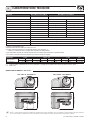 4
4
-
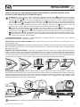 5
5
-
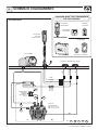 6
6
-
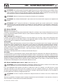 7
7
-
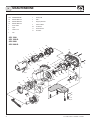 8
8
-
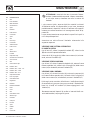 9
9
-
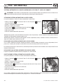 10
10
-
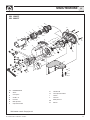 11
11
-
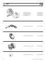 12
12
-
 13
13
-
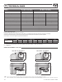 14
14
-
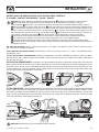 15
15
-
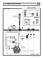 16
16
-
 17
17
-
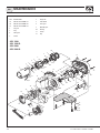 18
18
-
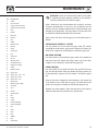 19
19
-
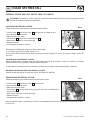 20
20
-
 21
21
-
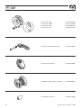 22
22
-
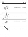 23
23
-
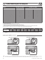 24
24
-
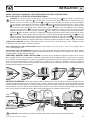 25
25
-
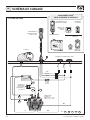 26
26
-
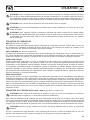 27
27
-
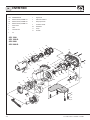 28
28
-
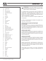 29
29
-
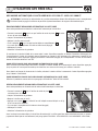 30
30
-
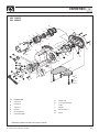 31
31
-
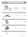 32
32
-
 33
33
-
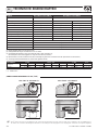 34
34
-
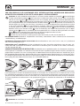 35
35
-
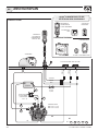 36
36
-
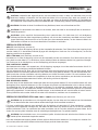 37
37
-
 38
38
-
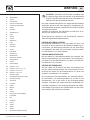 39
39
-
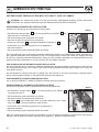 40
40
-
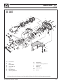 41
41
-
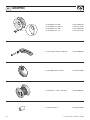 42
42
-
 43
43
-
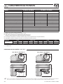 44
44
-
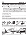 45
45
-
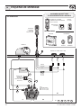 46
46
-
 47
47
-
 48
48
-
 49
49
-
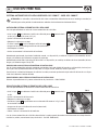 50
50
-
 51
51
-
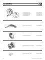 52
52
-
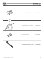 53
53
-
 54
54


Quick GP2 Genius 1500 Series Manual de usuario
- Tipo
- Manual de usuario
- Este manual también es adecuado para
en otros idiomas
Artículos relacionados
-
Quick GP2 Genius 1500 Series Manual Of Installation And Use
-
-
-
Quick HC3 1024 DB Manual de usuario
-
-
-
Quick F 1012 D Manual de usuario
-
-
-
Quick HRC 1002 Manual de usuario
