Kichler Lighting 15065AZT Manual de usuario
- Tipo
- Manual de usuario

• El alambre calibre 8 puede comprarse en longitud de 250’
(76 m.), 15503-BK
• El alambre calibre 10 puede comprarse en longitud de 250’
(76 m.), 15504-BK
• El alambre calibre 12 puede comprarse en longitudes de 75’
(22 m.), 15550-BK; 100’ (30 m.), 15501-BK; 250’ (76 m.),
15502-BK; 500’ (152 m.), 15505-BK; y 1000’ (304 m.),
15506-BK.
5) El artefacto no debe utilizarse con lámparas de halógeno, a
menoss que el artefacto esté marcado para usar con tales
lámparas.
6) Las conexiones de cableado se deben hacer con las conexiones
del(los) dispositivos) de conexión de cableado aprobados/ de
lalista,adecuadosparalaaplicación.Noexcedalasespeci
caciones de combinación de cableado del fabricante para el
tamaño y cantidad de conductores.
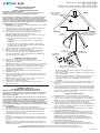
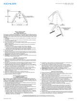
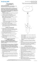
MONTAJE E INSTALACIÓN
1) Determine el lugar deseado dónde montar el artefacto.
2) Usando la Fig. A, marque la posición para perforar agujeros
piloto y para el agujero del canal de alambres (se se desea).
NOTA: La Fig. A está dibujada de tamaño real, y puede usarse
como un patrón o como referencia para dimensiones.
3) Perforeagujerospilotode3/32”(2mm.)enlasuperciede
montaje, en las posiciones marcadas. Si usa un agujero para el
canal de alambres también perfore ese ahora. Se sugiere que
sea de 1/4” (6 mm.) de diámetro.
4) Montelaabrazaderademontajealasuperciedemontaje.
usando los tornillos que se proveen.
5) Cuidadosamente resbale la pantalla de porcelana sobre la
abrazadera de montaje. El agujero en la parte posterior de la
pantalladebeencajarapretadoentrelasuperciedemontajey
la depresión en la parte posterior de la lengüeta.
NOTA:Silapantallanoparecesucientementeapretadao
parece demasia do apretada, ajuste doblando ligeramente la
lengüeta hacia adentro o afuera.
6) Desconecte o desenchufe el transformador.
7) Haga las conexiones de cableado usando las tuercas para
cables suministrados siguiendo las instrucciones de la bolsa.
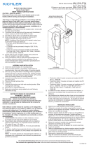
SAFETY INSTRUCTIONS
READ THIS FIRST
KEEP THESE INSTRUCTIONS
CAUTION – RISK OF SHOCK –
Disconnect Power at the main circuit breaker panel or main
fusebox before starting and during the installation.
This xture is intended for installation in accordance with the
National Electric Code (NEC) and Local code specications.
Failure to adhere to these codes and instructions may result in
serious injury and/or property damage and will void the warranty.
If you are not familiar with code requirements, installation by a
certied electrician is recommended.
1) WARNING:Thisxtureisnottobeinstalledwithin10feet(3M)
of a pool, spa or fountain.
2) Thisxtureistobeusedonlywithapowerunit(transformer)
rated a maximum of 300 W (25 AMPS) 15 volts.
3) The#18ga.xturewireisnotintendedfordirectburial.
4) Directburialratedwireistobeburiedaminimumof6"
(152mm) beneath the surface of the ground.
NOTE:IfadditionalDirectBurialwireisneeded,contactyour
local Kichler
®
landscape distributor.
•8GAwirecanbepurchasedinlengthof250’(76M),
15503-BK.
•10GAwirecanbepurchasedinlengthof250’(76M),
15504-BK.
•12GAwirecanbepurchasedinlengthsof100’(30M),
15501-BK; 250’ (76 M), 15502-BK; 500’ (152M), 15505-BK;
and 1000’ (304 M), 15506-BK.
5) Fixture shall not use a tungsten halogen lamp unless the
xtureismarkedforusewithsuchlamps.
6) Wiringconnectionsmustbemadewithapproved/listedwire
connection device(s) suitable for the application. Do not
exceedmanufacturers’wiringcombinationspecicationsfor
size and quantity of conductors.
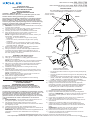
ASSEMBLY AND INSTALLATION
1) Determinedesiredlocationformountingxture.
2) Usingg.A,markpositionfordrililngpilotholesandfor
wirewayhole(ifdesired).
NOTE:Fig.Aisdrawnactualsize,itcanbeusedasatemplate
or be used as a template or be referenced for dimensions.
3) Drill3/32"(2mm)pilotholesinmountingsurfaceatpositions
marked.Ifusingawirewayholealsodrillthatatthistime.
Suggestedsize1/4"(6mm).
4) Assemblemountingbrackettomountingsurfaceusing
providedscrews.
5) Carefullyslipporcelainshadeovermountingbracket.Holein
backofshadeshouldtsnugbetweenmountingsurfaceand
dimpleonbacksideoftab.
NOTE: If shade does not seem snug enough or seems too
snug, adjust by slightly bending tab in or out.
6) Disconnect or unplug transformer.
7) Makewireconnectionsusingsuppliedwirenutsfollowing
instructions on bag.
INSTRUCCIONES DE SEGURIDAD
PRIMERO LEA ESTO
GUARDE ESTAS INSTRUCCIONES
PRECAUCIÓN – RIESGO DE DESCARGA ELÉCTRICA –
Desconecte la electricidad en el panel principal del interruptor
automático o caja principal de fusibles antes de comenzar y
durante la instalación.
Este artefacto se debe instalar de acuerdo con el Código Eléc-
trico Nacional (NEC, por sus siglas en inglés) y con las especi-
caciones del código local. No cumplir con estos códigos e
instrucciones puede resultar en lesiones graves y/ o en daños a
la propiedad y anulará la garantía. Si no está familiarizado con
los requisitos del código, la instalación se recomienda un electri-
cista certicado.
1) ADVERTENCIA: Este artefacto no debe instalarse a
menos de 10 pies (3 m) de una piscina (alberca), spa o fuente.
2) Este artefacto debe utilizarse solamente con una unidad de
potencia (tranformador) con capacidad nominal máxima de
300 vatios (25 amp.) 15 voltios.
3) El alambre del artefacto calibre No. 18 no es para soterrado
directo.
4) Elalambreclasicadoparasoterradodirectosedebeenterrar
unmínimode6pulgadas(152mm)debajodelasuperciedel
terreno.
NOTA: Si necesita alambre de soterrado directo adicional, co
muníquese con su distribuidor local Kichler® de productos de
jardinería ornamental.
For warranty information please visit: kichler.com/customer-care/warranty-information/landscape-warranty
Para informacion de la garantia por favor visite: kichler.com/customer-care/warranty-information/landscape-warranty
IS-15065-US
WIREWAY HOLE
AGUJERO DEL CANAL
DE ALAMBRES
PILOT HOLES
AGUJEROS
PILOTO
SCREWS
TORNILLOS
DIMPLE
DEPRESION
TAB
LENGUETA
MOUNTING BRACKET
PEDESTAL DE MONTAJE
FIG. A
SHADE
PANTALLA
We’re here to help 866-558-5706
Hrs: M-F 9am to 5pm EST
Estamos aquí para ayudarle 866-558-5706
Horario:Lunes-Viernes9ama5pmEST(horaocialdeleste)
La página se está cargando...

SAFETY INSTRUCTIONS
1) WARNING: This fixture is not to be installed within 10 feet (3M) of a pool, spa or fountain.
2) This fixture is to be used only with a power unit (transformer) rated a maximum of 300 W (25 AMPS) 15 volts.
3) The 8, 10, or 12 GA wiring is intended for shallow burial. Do not bury deeper than 6 inches (152 mm) below the surface.
NOTE: If more wire is needed, contact your local Kichler landscape distributor.
• 8 GA wire can be purchased in length of 250’ (76 M), 15503-BK.
• 10 GA wire can be purchased in length of 250’ (76 M), 15504-BK.
• 12 GA wire can be purchased in lengths of 75’ (22 M), 15500-BK; 100’ (30 M), 15501-BK; 250’ (76 M), 15502-BK; 500’ (152M), 15505-BK; and 1000’
(304 M) 15506-BK.
4) Fixture shall not use a tungsten halogen lamp unless the fixture is marked for use with such lamps.
INSTRUCCIONES DE SEGURIDAD
1) ADVERTENCIA: Este artefacto no debe instalarse a menos de 10 pies (3 m) de una piscina (alberca), spa o fuente.
2) Este artefacto debe utilizarse solamente con una unidad de potencia (tranformador) con capacidad nominal máxima de 300 vatios (25 amp.) 15 voltios.
3) Los alambres calibre 8, 10 y 12 son para entierro poco profundo. No entierre a más de 6 pulgadas (152 mm.) debajo de la superficie.
Nota: Si se necesita más alambre, comuníquese con su distribuidor de local Kichler de artículos para paisajes de terreno.
• El alambre calibre 8 puede comprarse en longitud de 250’ (76 m.), 15503-BK
• El alambre calibre 10 puede comprarse en longitud de 250’ (76 m.), 15504-BK
• El alambre calibre 12 puede comprarse en longitudes de 75’ (22 m.), 15550-BK; 100’ (30 m.), 15501-BK; 250’ (76 m.), 15502-BK; 500’ (152 m.), 15505-
BK; y 1000’ (304 m.), 15506-BK.
4) El artefacto no debe utilizarse con lámparas de halógeno, a menoss que el artefacto esté marcado para usar con tales lámparas.
A UTILISER UNIQUEMENT POUR LES SYSTÈMES D’ÉCLAIRAGE PAYSAGER
1) Le dispositif est accepté en tant que composant d’un système d’éclairage paysager lorsque la compatibilité de la combinaison étiquetée UL ou CSA
(ACNOR) doit être déterminée par CSA, UL respectivement ou les autorités d’inspection locales ayant compétence.
2) L’appareil doit étre connecté à un transformateur supplémentaire à basse tension approuvé pour une utilisation avec les systémes d’éclairage paysager.
3) Cet apareil doit étre connecté à un câblage secondaire du type suivant:
12GA 60°C type minimum;
SPT-3 combatible pour utilisation extreme;
ou câble d’éclairage paysager agréé.
ISTRUZIONI PER LA SICUREZZA
1) Avvertenza: l'unità non va installata entro 10 piedi (3 metri) da piscine, vasche idromassaggio o fontane.
2) Questa unità va usata solo con un'unità di alimentazione (trasformatore) con una portata massima di 300 W (25 ampere), 15 Volt.
3) Il filo da 8, 10 o 12 GA è inteso per buche poco profonde. NON scavare oltre 6 pollici (152 mm) sotto la superficie.
NOTA: se occorre più cavo, rivolgersi al distributore Kichler® di zona.
• Il filo da 8 GA può essere acquistato in lunghezze da 250 piedi (76 metri), 15503-BK.
• Il filo da 10 GA può essere acquistato in lunghezze da 250 piedi (76 metri), 15504-BK.
• Il filo da 12 GA può essere acquistato in lunghezza da 75 piedi (22 metri), 15500-BK; 100 piedi (30 metri), 15501-BK; 250 piedi (76 metri), 15502-BK;
500 piedi (152 metri), 5505-BK ed 1000 piedi (304 metri) 15506-BK.
4) L'unità non utilizza una lampadina alogena al tungsteno a meno che non sia contrassegnata per l'uso con tale tipo di lampadine.
SICHERHEITSANWEISUNGEN
1) ACHTUNG: Der Abstand zwischen der installierten Lampe oder Zubehör und einem Pool, Schwimmbad, einer Heilquelle, einem Heilbad oder Springbrunnen
muß mindestens 3 m betragen.
2) Diese Lampe darf nur mit Stromversorgungseinheiten (Wandlern) verwendet werden, die für maximal 300 Watt (25 Ampere Sekunden) x 15 Volt
ausgelegt sind.
3) Die 8, 10, oder 12 GA* Kabel sind für das Verlegen flach unter der Erde vorgesehen und sollten nicht tiefer als 15 cm unter der Oberfläche verlegt werden.
ANMERKUNG: Wenn Sie zusätzliches Kabel benötigen, wenden Sie sich bitte an Ihren örtlichen Händler für Kichler Landschaftsbeleuchtungen.
• 8 GA Kabel wird in einer Länge von 76 m angeboten: 15503-BK.
• 10 GA Kabel wird in einer Länge von 76 m angeboten: 15504-BK.
• 12 GA Kabel ist in den folgenden Längen erhältlich: 22 m (15500-BK), 30 m (15501-BK), 76 m (15502-BK), 152 m (15505-BK) und 304 m (15506-BK).
4) Tungsten (Wolfram)-Halogenlampen dürfen nur installiert werden, wenn die Bezeichnung der Beleuchtungsanlage die Verwendung dieser
Lampen ausdrücklich vorsieht.
IS-15065-EURDate Issued: 9/30/05
WARRANTY
WE WARRANT THE LANDSCAPE PRODUCTS FEATURED IN OUR LANDSCAPE LIGHTING CATALOG (WITH THE EXCEPTION OF LIGHT BULBS) FOR FIVE
YEARS AGAINST DEFECTS IN MATERIALS AND WORKMANSHIP IF IT WAS PROPERLY INSTALLED AND FAILED UNDER NORMAL OPERATING CONDI-
TIONS, PROVIDED IT IS RETURNED TO THE POINT OF PURCHASE, WHERE IT WILL BE REPAIRED OR, AS IT MAY BE DETERMINED, TO REPLACE THE
LANDSCAPE PRODUCT OR PARTS USED ON THAT PRODUCT.
GARANTIA
NOSOTROS GARANTIZAMOS POR CINCO ANOS LOS PRODUCTOS PANORAMICOS QUE OFRECEMOS EN NUESTRO CATALOGO DE ILUMINACION
PANORAMICA (CON EXCEPCION DE LAS BOMBILLAS), QUE ESTAN EXENTOS DE DEFECTOS DE MATERIALES Y MANO DE OBRA, SI SE INSTALARON
CORRECTAMIENTE Y FALLARON EN CONDICIONES DE OPERACION NORMAL, SIEMPRE QUE SE DEVUELVAN AL LUGAR DE COMPRA, DONDE SERAN
REPARADOS O, SEGUN PUEDA DETERMINARSE, SERAN
GARANTIE
NOUS GARANTISSONS LES PRODUITS DE PAYSAGES FIGURANT DANS NOTRE CATALOGUE DES LUMIERES PAYSAGISTES (A L’EXCEPTION DES
AMPOULES) PENDANT UNE PERIODE DE CINQ ANS CONTRE TOUS DEFAUTS DE MATERIAUX ET DE MAIN D’OEUVRE SOUS CONDITION QUE L’IN-
STALLATION AIT ETE EFFECTUEE CORRECTEMENT ET QUE LES PROBLEMES SE SOIENT PRODUITS AU COURS D’UN EMPLOI NORMAL. LE PRODUIT
DOIT ETRE RETOURNE AU LIEU DE VENTE OU IL SERA REPARE OU, SUITE A UNE EVALUATION, LE PRODUIT DE PAYAGE OU LES PIECES QUI LE COM-
POSENT SERONT REMPLACEES.
GARANTIE
WIR GARANTIEREN DIE LANDSCHAFTSPRODUKTE, DIE IN UNSEREM KATALOG MIT LANDSCHAFTSBELEUCHUNGSSYSTEMEN ANGEBOTEN WER-
DEN (MIT AUSNAHME DER GLÜHBIRNEN), FÜR FÜNF JAHRE. DIE GARANTIE DECKT MATERIALFEHLER UND DIE HANDWERKLICHE AUSFÜHRUNG,
SOLANGE DIE TEILE FACHGERECHT EINGEBAUT WERDEN UND DIE MÄNGEL UNTER NORMALEN BEDINGUNGEN DER VERWENDUNG AUFTRETEN,
VORAUSGESETZT, DASS DAS TEIL/ PRODUKT AM EINKAUFSORT ZURÜCKGEGEBEN WIRD. DAS PRODUKT WIRD DORT REPARIERT ODER, JE NACH
BEURTEILUNG, KANN DAS TEIL / LANDSCHAFTSBELEUCHTUNGSSYSTEM AUCH ERSETZT WERDEN.
GARANZIA
GARANTIAMO I PRODOTTI DA ESTERNO CONTENUTI IN QUESTO CATALOGO (AD ECCEZIONE DELLE LAMPADINE) PER UN PERIODO DI CINQUE ANNI
DA DIFETTI DI MATERIALE E MANODOPERA, SE DEBITAMENTE INSTALLATI, CHE SI GUASTANO IN CONDIZIONI OPERATIVE REGOLARI, AMMESSO
CHE VENGANO RESTITUITI AL CENTRO DI ACQUISTO, DOVE VERRANNO RIPARATI, OPPURE, A SECONDA DEL CASO, SOSTITUITI CON PRODOTTI O
PARTI DA ESTERNO USATI SUL PRODOTTO IN QUESTIONE.

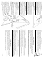
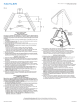
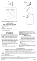
PILOT HOLES
AGUJEROS PILOTO
TROUS PILOTES
VORBOHRUNGEN
FORI PILOTA
FIG. A
SCREW
TORNILLO
VIS
SCHRAUBEN
VITI
TAB
LENGÜETA
ARRIÈRE DE LA PATTE
FLACHSTECKZUNGE
LINGUETTA
MOUNTING BRACKET
PEDESTAL DE MONTAJE
SUPPORT DE FIXATION
HALTERUNG
PIASTRA DI MONTAGGIO
DIMPLE
DEPRESIÓN
CRAN
HINTERSEITE
CONCAVITÀ
IS-15065-EUR
ASSEMBLY AND INSTALLATION
1) Determine desired location for mounting fixture.
2) Using Fig. A, mark position for drililng pilot holes and for wireway hole (if desired).
NOTE: Fig. A is drawn actual size, it can be used as a template or be used as a tem-
plate or be referenced for dimensions.
3) Drill 3/32” (2 mm) pilot holes in mounting surface at positions marked. If using a wire-
way hole also drill that at this time. Suggested size 1/4” (6 mm).
4) Assemble mounting bracket to mounting surface using provided screws.
5) Carefully slip porcelain shade over mounting bracket. Hole in back of shade should fit
snug between mounting surface and dimple on backside of tab.
NOTE: If shade does not seem snug enough or seems too snug, adjust by slightly
bending tab in or out.
6) Turn off power and disconnect or unplug transformer.
7) Run wire and make connections by following Quic Disc
®
instructions.
8) Insert bulb.
MONTAJE E INSTALACIÓN
1) Determine el lugar deseado dónde montar el artefacto.
2) Usando la Fig. A, marque la posición para perforar agujeros piloto y para el agujero del
canal de alambres (se se desea).
NOTA: La Fig. A está dibujada de tamaño real, y puede usarse como un patrón o como
referencia para dimensiones.
3) Perfore agujeros piloto de 3/32” (2 mm.) en la superficie de montaje, en las posiciones
marcadas. Si usa un agujero para el canal de alambres también perfore ese ahora. Se
sugiere que sea de 1/4” (6 mm.) de diámetro.
4) Monte la abrazadera de montaje a la superficie de montaje. usando los tornillos que se
proveen.
5) Cuidadosamente resbale la pantalla de porcelana sobre la abrazadera de montaje. El
agujero en la parte posterior de la pantalla debe encajar apretado entre la superficie de
montaje y la depresión en la parte posterior de la lengüeta.
NOTA: Si la pantalla no parece suficientemente apretada o parece demasiado apreta-
da, ajuste doblando ligeramente la lengüeta hacia adentro o afuera.
6) Apague la alimentación de energia y desconecte o desenchufe el transformador.
7) Corra el alambre y haga las conexiones siguiendo las instrucciones de Quic Disc.
8) Inserte la bombilla.
MONTAGE ET INSTALLATION
1) Déterminer l’endroit ou l’appareil sera installé.
2) Marquer la position des trous pilotes et du trou pour le guide-fil (Figure A.).
REMARQUE: La Figure A étant à l’échelle, elle peut être utilisée comme gabarit ou servir de
référence pour les dimensions.
3) Percer des trous pilotes de 2 mm (3/32”). Si un guide-fil est utilisé, percer également un trou
de 6 mm (1/4’).
4) Fixer le support de fixation sur la surface de montage avec les vis fournies.
5) Glisser avec précaution l’abat-jour en porcelaine sur le support de fixation. Le trou situé à
l’arrière de l’abat-jour doit se placer entre la surface de fixation et le cran situé à l’arrière
de la patte. REMARQUE: Si l’abat-jour n’est pas bien bloqué, courber légèrement la
patte vers l’avant ou vers l’arrière.
6) Couper l’alimentation électrique et déconnecter ou débrancer le transformateur.
7) Passer le fil électrique et faire les brancements en suivant le mode d’emploi du Quic Disc
®
.
8) Installer l’ampoule électrique.
MONTAGEANLEITUNG
1) Bestimmen Sie einen Platz für Ihre Lampe.
2) Wie in Abbildung A beschrieben, markieren Sie die Stellen für die Vorbohrungen und
das Loch für die Leitungsführung (nach Ihrem Plan).
ANMERKUNG: Abbildung A ist maßstabsgerecht gezeichnet und kann als Vorlage
oder zum Maßnehmen verwendet werden.
3) Machen Sie in den markierten Positionen 2 mm Vorbohrungen in der Montagefläche.
Wenn gewünscht, bohren Sie jetzt auch das Loch für die Leitungsführung. Die
vorgeschlagene Weite ist 6 mm.
4) Befestigen Sie die Halterung mit den einbegriffenen Schrauben an der
Montagefläche.
5) Gleiten Sie den Porzellanschirm vorsichtig über die Halterung. Das Loch in der
Rückseite des Lampenschirms sollte sich genau zwischen Montagefläche und der
kleinen Vertiefung an der Hinterseite der Flachsteckzunge befinden.
ANMERKUNG: Sollte der Lampenschirm nicht richtig fest sitzen oder zu fest sitzen,
können Sie die Flachsteckzunge ein wenig vorwärts oder rückwärts biegen.
6) Den Strom ausschalten. Den Umformer abschalten oder den Stecker herausziehen.
7) Die Leitung legen und dann nach den folgenden Quic Disc
®
Anweisungen die
Verbindungen herstellen.
8) Setzen Sie die Glühbirne ein.
ISTRUZIONI PER IL MONTAGGIO
1) Determinare la posizione desiderata per l'attrezzo di montaggio.
2) Consultando la Figura A, contrassegnare la posizione per praticare i fori pilota
ed i fori per la canaletta (se desiderato). NOTA: la Figura A riporta le dimensioni
effettive e può essere usata come sagoma o consultata come riferimento
per le dimensioni.
3) Praticare fori pilota da 2 mm nella superficie di montaggio, sulle posizioni
contrassegnate. Se si utilizza un foro per canaletta, praticarne uno ora. Le ‘
dimensioni suggerite sono 6 mm.
4) Montare la piastra alla superficie di montaggio utilizzando le viti in dotazione.
5) Far scorrere con attenzione il paralume in porcellana sulla piastra di montaggio.
Il foro sul retro del paralume dovrebbe assestarsi bene tra la superficie di
montaggio e la concavità sul lato posteriore della linguetta. NOTA: se il paralume non sembra
essere ben assestato o risulta troppo serrato, regolare leggermente piegando la linguetta in
dentro o in fuori.
6) Togliere corrente e scollegare o staccare il trasformatore.
7) Far passare il filo ed effettuare le connessioni attenendosi alle istruzioni Quic Disc
®
.
8) Inserire la lampadina.
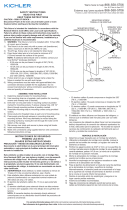
QUIC DISC
®
WIRING INSTRUCTIONS
Turn off power.
The full length of the 18 GA fixture wire may be used to connect with the 10 GA or 12 GA cable provided the following conditions are met:
• Wiring is to be protected by routing close to the fixture or accessory or secured to a building structure such as house or deck.
• 18 GA fixture wiring is to be cut off so that it is attached to the connector within 6 inches of the fixture or building structure.
• If it is necessary to make the connections underground, then no more than 6 inches of the 18 GA fixture wire is to be buried.
The Quic Disc
®
connector accommodates one 18 GA fixture wire and one 10 GA or one 12 GA supply wire.
Place the 10 gauge supply wire across the area marked 10 GA on Quic Disc
®
or place the 12 gauge supply wire across the area marked 12 GA on
Quic Disc
®
.
Place the 18 gauge fixture wire across the area marked 18 GA on the Quic Disc
®
. After the wires are in place, connect the top of the Quic Disc
®
to
the base with supplied screw, making sure that the wires remain flat in the bottom portion of the Quic Disc
®
, and the screw is tightened all the way
down.
The copper contacts will automatically pierce the wires’ insulation. Excess 18 GA fixture wire that sticks out the end of the Quic
Disc
®
is to to be cut off.
QUIC DISC® ANSCHLUSSANLEITUNGEN
Den Strom abschalten.
Die volle Länge des 18 GA Lampenkabels kann für den Anschluß an das 10 GA oder 12 GA Kabel verwendet werden, solange die folgenden Bedingungen erfüllt sind:
• Zum Schutz der Leitung müssen Kabel nahe der Lampe und Zubehör verlegt werden oder unmittelbar an einer baulichen Struktur angebracht sein, wie z.B. an einemHaus oder
einer Terrasse.
• Das 18 GA-Kabel muß abgeschnitten werden, so daß es innerhalb von 15,24 cm vom Beleuchungssystem oder einem Gebäude an eine Buchse angeschlossen ist.
• Wenn der Anschluß unterhalb der Erde gemacht werden muß, dürfen nicht mehr als 15,24 cm des 18 GA-Kabels unter der Erde verlegt sein.
Der Quic Disc
®
Konnektor kann ein 18 GA-Kabel und ein 10 GA- oder 12 GA-Kabel für die Stromversorgung aufnehmen.
Auf dem Quic Disc
®
Konnektor das 10 GA-Kabel für die Stromzufuhr über den Bereich mit der Markierung "10 GA" oder das 12 GA-Kabel über den "12 GA" Bereich legen.
Auf dem Quic Disc
®
Konnektor das 18 GA-Lampenkabel über den Bereich mit der Markierung "18 GA" legen. Mit den Kabeln richtig angeordnet, legen Sie den Quic Disc
®
Konnektor-Deckel auf das Unterteil und befestigen Sie den Deckel locker mit der beiliegenden Schraube. Wenn Sie sicher sind, daß die Kabel flach im Unterteil des Quic Disc®
Konnektors liegen, ziehen Sie die Schraube so fest wie möglich an.
Die Kupferkontakte brechen automatisch durch die Kabelisolierung. Überschüssiges 18 GA-Kabel, das über den Quic Disc
®
Konnektor hinausreicht, muß abgeschnitten werden.
ISTRUZIONI PER IL CABLAGGIO QUIC DISC
®
Togliere corrente.
Potrebbe essere necessario utilizzare l'intera lunghezza del filo dell'attrezzo da 18 GA per collegare il cavo da 10 GA o da 12 GA, ammesso che esistano le seguenti condizioni:
• Il cablaggio deve essere protetto disponendolo accanto all'attrezzo o all'accessorio o fissandolo ad una struttura, quale la casa o il balcone in legno.
• Il filo dell'attrezzo da 18 GA va tagliato di modo che sia fissato al connettore senza superare una distanza di 6 pollici dall'attrezzo stesso o dalla struttura in questione.
• Occorre effettuare collegamenti sotterranei, senza sotterrare comunque non più di 6 pollici del filo dell'attrezzo da 18 GA.
Il connettore Quic Disc
®
prevede l'utilizzo di un filo dell'attrezzo da 18 GA e di due fili di alimentazione, uno da 10 GA ed uno da 12 GA.
Sistemare il filo di alimentazione da 10 GA attraverso l'area contrassegnata 10 GA su Quic Disc
®
, oppure il filo di alimentazione da 12 GA attraverso l'area contrassegnata 12 GA
su Quic Disc
®
.
Sistemare il filo dell'attrezzo da 18 GA attraverso l'area contrassegnata 18 GA su Quic Disc
®
. Dopo aver sistemato i fili, collegare la sommità del Quic Disc
®
alla base avvalendosi
della vite in dotazione ed accertandosi che i fili restino piatti nella sezione inferiore del Quic Disc
®
e che la vite sia serrata fino in fondo.
I contatti in rame perforano automaticamente l'isolamento dei fili. Tagliare il filo dell'attrezzo da 18 GA che spunta dall'estremità del Quic Disc
®
.
INSTRUCCIONES DE ALAMBRADO DE QUIC DISC
®
Apague la alimentación de energía.
El largo total del alambre calibre 18 del artefacto se puede utilizar para conectar con un cable calibre 10 ó 12, con tal que se cumplan las condiciones siguientes:
• El alambrado se debe proteger encaminando cerca al artefacto o accesorio o asegurado a la estructura de un edificio, tal como una casa o cubierta.
• El alambrado calibre 18 del artefacto debe cortarse de manera que se una al conector dentro de las 6 pulgadas del artefacto o de la estructura del edificio.
• Si fuere necesario hacer las conexiones bajo tierra, como máximo 6 pulgadas del alambre calibre 18 del artefacto se debe enterrar.
El conector Quic Disc
®
acomoda un alambre calibre 18 del artefacto y uno calibre 10 o un alambre de alimentación calibre 12.
Coloque el alambre de alimentación calibre 10 a través del área marcada calibre 10 en el Quic Disc
®
o ponga el alambre de alimentación calibre 12 a través del área marcada cal-
ibre 12 en el Quic Disc
®
.
Ponga el alambre calibre 18 del artefacto a través del área marcada calibre 18 en el Quic Disc
®
Después que los alambres estén en su lugar, conecte el tope del Quic Disc
®
a la
base con el tornillo que se provee, asegurándose de que los alambres permanezcan en la porción inferior del Quic Disc
®
, y el tornillo esté todo apretado hacia abajo.
Los contactos de cobre automáticamente perforarán la aislación de los alambres. El exceso de alambre calibre 18 del artefacto que sobresale del extremo Quic Disc
®
debe cortarse.
INSTRUCTIONS DE CBLAGE ÉLECTRIQUE AVEC UN QUIC DISC
®
Couper le courant d'alimentation.
Toute la longueur du fil électrique de calibre 18 peut être utilisée pour le branchement avec le fil électrique de calibre 10 ou 12 si les conditions suivantes sont remplies :
• Le câblage doit être protégé soit par le cheminement des fils à proximité de l'appareil, par un accessoire ou bien il doit être fixé à la structure d'une construction telle qu'une maison ou
une terrasse.
• Les fils de calibre 18 doivent être coupés de manière à pouvoir être reliés au connecteur à une distance maximum de 6 pouces du luminaire ou de la construction.
• Si les branchements doivent être faits sous terre, pas plus de 6 pouces de fils de calibre 18 doivent être enterrés.
Le connecteur Quic Disc
®
s'adapte à un fil électrique de calibre 18, à un fil de calibre 10 ou à un fil de calibre 12.
Poser le fil électrique de calibre 10 sur le Quic Disc
®
en travers de l'endroit marqué calibre 10 ou celui de calibre 12 en travers de l'endroit marqué calibre 12.
Poser le fil d'alimentation du luminaire en travers de l'endroit marqué calibre 18. Lorsque les fils sont en place, connecter la partie supérieure du Quic Disc
®
à la base avec la vis
fournie. S'assurer que les fils sont bien à plat dans la partie inférieure du Quic Disc
®
et que la vis est serrée à fond.
Les contacts en cuivre perceront automatiquement l'isolement des fils. Couper le fil d'alimentation de calibre 18 qui dépasse du Quic Disc“.
Transcripción de documentos
We’re here to help Estamos aquí para ayudarle SAFETY INSTRUCTIONS READ THIS FIRST KEEP THESE INSTRUCTIONS CAUTION – RISK OF SHOCK – Disconnect Power at the main circuit breaker panel or main fusebox before starting and during the installation. This fixture is intended for installation in accordance with the National Electric Code (NEC) and Local code specifications. Failure to adhere to these codes and instructions may result in serious injury and/or property damage and will void the warranty. If you are not familiar with code requirements, installation by a certified electrician is recommended. 1) WARNING: This fixture is not to be installed within 10 feet (3M) of a pool, spa or fountain. 2) This fixture is to be used only with a power unit (transformer) rated a maximum of 300 W (25 AMPS) 15 volts. 3) The #18 ga. fixture wire is not intended for direct burial. 4) Direct burial rated wire is to be buried a minimum of 6" (152mm) beneath the surface of the ground. NOTE: If additional Direct Burial wire is needed, contact your local Kichler® landscape distributor. • 8 GA wire can be purchased in length of 250’ (76 M), 15503-BK. • 10 GA wire can be purchased in length of 250’ (76 M), 15504-BK. • 12 GA wire can be purchased in lengths of 100’ (30 M), 15501-BK; 250’ (76 M), 15502-BK; 500’ (152M), 15505-BK; and 1000’ (304 M), 15506-BK. 5) Fixture shall not use a tungsten halogen lamp unless the fixture is marked for use with such lamps. 6) Wiring connections must be made with approved/listed wire connection device(s) suitable for the application. Do not exceed manufacturers’ wiring combination specifications for size and quantity of conductors. 1) 2) 3) 4) 5) 6) 7) ASSEMBLY AND INSTALLATION Determine desired location for mounting fixture. Using fig. A, mark position for drililng pilot holes and for wireway hole (if desired). NOTE: Fig. A is drawn actual size, it can be used as a template or be used as a template or be referenced for dimensions. Drill 3/32" (2 mm) pilot holes in mounting surface at positions marked. If using a wireway hole also drill that at this time. Suggested size 1/4" (6 mm). Assemble mounting bracket to mounting surface using provided screws. Carefully slip porcelain shade over mounting bracket. Hole in back of shade should fit snug between mounting surface and dimple on backside of tab. NOTE: If shade does not seem snug enough or seems too snug, adjust by slightly bending tab in or out. Disconnect or unplug transformer. Make wire connections using supplied wire nuts following instructions on bag. INSTRUCCIONES DE SEGURIDAD PRIMERO LEA ESTO GUARDE ESTAS INSTRUCCIONES PRECAUCIÓN – RIESGO DE DESCARGA ELÉCTRICA – Desconecte la electricidad en el panel principal del interruptor automático o caja principal de fusibles antes de comenzar y durante la instalación. Este artefacto se debe instalar de acuerdo con el Código Eléctrico Nacional (NEC, por sus siglas en inglés) y con las especificaciones del código local. No cumplir con estos códigos e instrucciones puede resultar en lesiones graves y/ o en daños a la propiedad y anulará la garantía. Si no está familiarizado con los requisitos del código, la instalación se recomienda un electricista certificado. 1) ADVERTENCIA: Este artefacto no debe instalarse a menos de 10 pies (3 m) de una piscina (alberca), spa o fuente. 2) Este artefacto debe utilizarse solamente con una unidad de potencia (tranformador) con capacidad nominal máxima de 300 vatios (25 amp.) 15 voltios. 3) El alambre del artefacto calibre No. 18 no es para soterrado directo. 4) El alambre clasificado para soterrado directo se debe enterrar un mínimo de 6 pulgadas (152 mm) debajo de la superficie del terreno. NOTA: Si necesita alambre de soterrado directo adicional, co muníquese con su distribuidor local Kichler® de productos de jardinería ornamental. 866-558-5706 Hrs: M-F 9am to 5pm EST 866-558-5706 Horario: Lunes-Viernes 9am a 5pm EST (hora oficial del este) FIG. A PILOT HOLES AGUJEROS PILOTO SHADE PANTALLA TAB LENGUETA WIREWAY HOLE AGUJERO DEL CANAL DE ALAMBRES DIMPLE DEPRESION SCREWS TORNILLOS MOUNTING BRACKET PEDESTAL DE MONTAJE • El alambre calibre 8 puede comprarse en longitud de 250’ (76 m.), 15503-BK • El alambre calibre 10 puede comprarse en longitud de 250’ (76 m.), 15504-BK • El alambre calibre 12 puede comprarse en longitudes de 75’ (22 m.), 15550-BK; 100’ (30 m.), 15501-BK; 250’ (76 m.), 15502-BK; 500’ (152 m.), 15505-BK; y 1000’ (304 m.), 15506-BK. 5) El artefacto no debe utilizarse con lámparas de halógeno, a menoss que el artefacto esté marcado para usar con tales lámparas. 6) Las conexiones de cableado se deben hacer con las conexiones del(los) dispositivos) de conexión de cableado aprobados/ de la lista, adecuados para la aplicación. No exceda las especifi caciones de combinación de cableado del fabricante para el tamaño y cantidad de conductores. 1) 2) 3) 4) 5) 6) 7) MONTAJE E INSTALACIÓN Determine el lugar deseado dónde montar el artefacto. Usando la Fig. A, marque la posición para perforar agujeros piloto y para el agujero del canal de alambres (se se desea). NOTA: La Fig. A está dibujada de tamaño real, y puede usarse como un patrón o como referencia para dimensiones. Perfore agujeros piloto de 3/32” (2 mm.) en la superficie de montaje, en las posiciones marcadas. Si usa un agujero para el canal de alambres también perfore ese ahora. Se sugiere que sea de 1/4” (6 mm.) de diámetro. Monte la abrazadera de montaje a la superficie de montaje. usando los tornillos que se proveen. Cuidadosamente resbale la pantalla de porcelana sobre la abrazadera de montaje. El agujero en la parte posterior de la pantalla debe encajar apretado entre la superficie de montaje y la depresión en la parte posterior de la lengüeta. NOTA: Si la pantalla no parece suficientemente apretada o parece demasia do apretada, ajuste doblando ligeramente la lengüeta hacia adentro o afuera. Desconecte o desenchufe el transformador. Haga las conexiones de cableado usando las tuercas para cables suministrados siguiendo las instrucciones de la bolsa. For warranty information please visit: kichler.com/customer-care/warranty-information/landscape-warranty Para informacion de la garantia por favor visite: kichler.com/customer-care/warranty-information/landscape-warranty IS-15065-US WARRANTY WE WARRANT THE LANDSCAPE PRODUCTS FEATURED IN OUR LANDSCAPE LIGHTING CATALOG (WITH THE EXCEPTION OF LIGHT BULBS) FOR FIVE YEARS AGAINST DEFECTS IN MATERIALS AND WORKMANSHIP IF IT WAS PROPERLY INSTALLED AND FAILED UNDER NORMAL OPERATING CONDITIONS, PROVIDED IT IS RETURNED TO THE POINT OF PURCHASE, WHERE IT WILL BE REPAIRED OR, AS IT MAY BE DETERMINED, TO REPLACE THE LANDSCAPE PRODUCT OR PARTS USED ON THAT PRODUCT. GARANTIA NOSOTROS GARANTIZAMOS POR CINCO ANOS LOS PRODUCTOS PANORAMICOS QUE OFRECEMOS EN NUESTRO CATALOGO DE ILUMINACION PANORAMICA (CON EXCEPCION DE LAS BOMBILLAS), QUE ESTAN EXENTOS DE DEFECTOS DE MATERIALES Y MANO DE OBRA, SI SE INSTALARON CORRECTAMIENTE Y FALLARON EN CONDICIONES DE OPERACION NORMAL, SIEMPRE QUE SE DEVUELVAN AL LUGAR DE COMPRA, DONDE SERAN REPARADOS O, SEGUN PUEDA DETERMINARSE, SERAN GARANTIE NOUS GARANTISSONS LES PRODUITS DE PAYSAGES FIGURANT DANS NOTRE CATALOGUE DES LUMIERES PAYSAGISTES (A L’EXCEPTION DES AMPOULES) PENDANT UNE PERIODE DE CINQ ANS CONTRE TOUS DEFAUTS DE MATERIAUX ET DE MAIN D’OEUVRE SOUS CONDITION QUE L’INSTALLATION AIT ETE EFFECTUEE CORRECTEMENT ET QUE LES PROBLEMES SE SOIENT PRODUITS AU COURS D’UN EMPLOI NORMAL. LE PRODUIT DOIT ETRE RETOURNE AU LIEU DE VENTE OU IL SERA REPARE OU, SUITE A UNE EVALUATION, LE PRODUIT DE PAYAGE OU LES PIECES QUI LE COMPOSENT SERONT REMPLACEES. GARANTIE WIR GARANTIEREN DIE LANDSCHAFTSPRODUKTE, DIE IN UNSEREM KATALOG MIT LANDSCHAFTSBELEUCHUNGSSYSTEMEN ANGEBOTEN WERDEN (MIT AUSNAHME DER GLÜHBIRNEN), FÜR FÜNF JAHRE. DIE GARANTIE DECKT MATERIALFEHLER UND DIE HANDWERKLICHE AUSFÜHRUNG, SOLANGE DIE TEILE FACHGERECHT EINGEBAUT WERDEN UND DIE MÄNGEL UNTER NORMALEN BEDINGUNGEN DER VERWENDUNG AUFTRETEN, VORAUSGESETZT, DASS DAS TEIL/ PRODUKT AM EINKAUFSORT ZURÜCKGEGEBEN WIRD. DAS PRODUKT WIRD DORT REPARIERT ODER, JE NACH BEURTEILUNG, KANN DAS TEIL / LANDSCHAFTSBELEUCHTUNGSSYSTEM AUCH ERSETZT WERDEN. GARANZIA GARANTIAMO I PRODOTTI DA ESTERNO CONTENUTI IN QUESTO CATALOGO (AD ECCEZIONE DELLE LAMPADINE) PER UN PERIODO DI CINQUE ANNI DA DIFETTI DI MATERIALE E MANODOPERA, SE DEBITAMENTE INSTALLATI, CHE SI GUASTANO IN CONDIZIONI OPERATIVE REGOLARI, AMMESSO CHE VENGANO RESTITUITI AL CENTRO DI ACQUISTO, DOVE VERRANNO RIPARATI, OPPURE, A SECONDA DEL CASO, SOSTITUITI CON PRODOTTI O PARTI DA ESTERNO USATI SUL PRODOTTO IN QUESTIONE. 1) 2) 3) 4) SAFETY INSTRUCTIONS WARNING: This fixture is not to be installed within 10 feet (3M) of a pool, spa or fountain. This fixture is to be used only with a power unit (transformer) rated a maximum of 300 W (25 AMPS) 15 volts. The 8, 10, or 12 GA wiring is intended for shallow burial. Do not bury deeper than 6 inches (152 mm) below the surface. NOTE: If more wire is needed, contact your local Kichler landscape distributor. • 8 GA wire can be purchased in length of 250’ (76 M), 15503-BK. • 10 GA wire can be purchased in length of 250’ (76 M), 15504-BK. • 12 GA wire can be purchased in lengths of 75’ (22 M), 15500-BK; 100’ (30 M), 15501-BK; 250’ (76 M), 15502-BK; 500’ (152M), 15505-BK; and 1000’ (304 M) 15506-BK. Fixture shall not use a tungsten halogen lamp unless the fixture is marked for use with such lamps. INSTRUCCIONES DE SEGURIDAD 1) ADVERTENCIA: Este artefacto no debe instalarse a menos de 10 pies (3 m) de una piscina (alberca), spa o fuente. 2) Este artefacto debe utilizarse solamente con una unidad de potencia (tranformador) con capacidad nominal máxima de 300 vatios (25 amp.) 15 voltios. 3) Los alambres calibre 8, 10 y 12 son para entierro poco profundo. No entierre a más de 6 pulgadas (152 mm.) debajo de la superficie. Nota: Si se necesita más alambre, comuníquese con su distribuidor de local Kichler de artículos para paisajes de terreno. • El alambre calibre 8 puede comprarse en longitud de 250’ (76 m.), 15503-BK • El alambre calibre 10 puede comprarse en longitud de 250’ (76 m.), 15504-BK • El alambre calibre 12 puede comprarse en longitudes de 75’ (22 m.), 15550-BK; 100’ (30 m.), 15501-BK; 250’ (76 m.), 15502-BK; 500’ (152 m.), 15505BK; y 1000’ (304 m.), 15506-BK. 4) El artefacto no debe utilizarse con lámparas de halógeno, a menoss que el artefacto esté marcado para usar con tales lámparas. A UTILISER UNIQUEMENT POUR LES SYSTÈMES D’ÉCLAIRAGE PAYSAGER 1) Le dispositif est accepté en tant que composant d’un système d’éclairage paysager lorsque la compatibilité de la combinaison étiquetée UL ou CSA (ACNOR) doit être déterminée par CSA, UL respectivement ou les autorités d’inspection locales ayant compétence. 2) L’appareil doit étre connecté à un transformateur supplémentaire à basse tension approuvé pour une utilisation avec les systémes d’éclairage paysager. 3) Cet apareil doit étre connecté à un câblage secondaire du type suivant: 12GA 60°C type minimum; SPT-3 combatible pour utilisation extreme; ou câble d’éclairage paysager agréé. SICHERHEITSANWEISUNGEN 1) ACHTUNG: Der Abstand zwischen der installierten Lampe oder Zubehör und einem Pool, Schwimmbad, einer Heilquelle, einem Heilbad oder Springbrunnen muß mindestens 3 m betragen. 2) Diese Lampe darf nur mit Stromversorgungseinheiten (Wandlern) verwendet werden, die für maximal 300 Watt (25 Ampere Sekunden) x 15 Volt ausgelegt sind. 3) Die 8, 10, oder 12 GA* Kabel sind für das Verlegen flach unter der Erde vorgesehen und sollten nicht tiefer als 15 cm unter der Oberfläche verlegt werden. ANMERKUNG: Wenn Sie zusätzliches Kabel benötigen, wenden Sie sich bitte an Ihren örtlichen Händler für Kichler Landschaftsbeleuchtungen. • 8 GA Kabel wird in einer Länge von 76 m angeboten: 15503-BK. • 10 GA Kabel wird in einer Länge von 76 m angeboten: 15504-BK. • 12 GA Kabel ist in den folgenden Längen erhältlich: 22 m (15500-BK), 30 m (15501-BK), 76 m (15502-BK), 152 m (15505-BK) und 304 m (15506-BK). 4) Tungsten (Wolfram)-Halogenlampen dürfen nur installiert werden, wenn die Bezeichnung der Beleuchtungsanlage die Verwendung dieser Lampen ausdrücklich vorsieht. IS-15065-EUR ISTRUZIONI PER LA SICUREZZA 1) Avvertenza: l'unità non va installata entro 10 piedi (3 metri) da piscine, vasche idromassaggio o fontane. 2) Questa unità va usata solo con un'unità di alimentazione (trasformatore) con una portata massima di 300 W (25 ampere), 15 Volt. 3) Il filo da 8, 10 o 12 GA è inteso per buche poco profonde. NON scavare oltre 6 pollici (152 mm) sotto la superficie. NOTA: se occorre più cavo, rivolgersi al distributore Kichler® di zona. • Il filo da 8 GA può essere acquistato in lunghezze da 250 piedi (76 metri), 15503-BK. • Il filo da 10 GA può essere acquistato in lunghezze da 250 piedi (76 metri), 15504-BK. • Il filo da 12 GA può essere acquistato in lunghezza da 75 piedi (22 metri), 15500-BK; 100 piedi (30 metri), 15501-BK; 250 piedi (76 metri), 15502-BK; 500 piedi (152 metri), 5505-BK ed 1000 piedi (304 metri) 15506-BK. 4) L'unità non utilizza una lampadina alogena al tungsteno a meno che non sia contrassegnata per l'uso con tale tipo di lampadine. Date Issued: 9/30/05 ASSEMBLY AND INSTALLATION 1) Determine desired location for mounting fixture. 2) Using Fig. A, mark position for drililng pilot holes and for wireway hole (if desired). NOTE: Fig. A is drawn actual size, it can be used as a template or be used as a template or be referenced for dimensions. 3) Drill 3/32” (2 mm) pilot holes in mounting surface at positions marked. If using a wireway hole also drill that at this time. Suggested size 1/4” (6 mm). 4) Assemble mounting bracket to mounting surface using provided screws. 5) Carefully slip porcelain shade over mounting bracket. Hole in back of shade should fit snug between mounting surface and dimple on backside of tab. NOTE: If shade does not seem snug enough or seems too snug, adjust by slightly bending tab in or out. 6) Turn off power and disconnect or unplug transformer. 7) Run wire and make connections by following Quic Disc® instructions. 8) Insert bulb. PILOT HOLES AGUJEROS PILOTO TROUS PILOTES VORBOHRUNGEN FORI PILOTA SCREW TORNILLO VIS SCHRAUBEN VITI MOUNTING BRACKET PEDESTAL DE MONTAJE SUPPORT DE FIXATION HALTERUNG PIASTRA DI MONTAGGIO MONTAGE ET INSTALLATION Déterminer l’endroit ou l’appareil sera installé. Marquer la position des trous pilotes et du trou pour le guide-fil (Figure A.). REMARQUE: La Figure A étant à l’échelle, elle peut être utilisée comme gabarit ou servir de référence pour les dimensions. Percer des trous pilotes de 2 mm (3/32”). Si un guide-fil est utilisé, percer également un trou de 6 mm (1/4’). Fixer le support de fixation sur la surface de montage avec les vis fournies. Glisser avec précaution l’abat-jour en porcelaine sur le support de fixation. Le trou situé à l’arrière de l’abat-jour doit se placer entre la surface de fixation et le cran situé à l’arrière de la patte. REMARQUE: Si l’abat-jour n’est pas bien bloqué, courber légèrement la patte vers l’avant ou vers l’arrière. Couper l’alimentation électrique et déconnecter ou débrancer le transformateur. Passer le fil électrique et faire les brancements en suivant le mode d’emploi du Quic Disc®. Installer l’ampoule électrique. MONTAJE E INSTALACIÓN 1) Determine el lugar deseado dónde montar el artefacto. 2) Usando la Fig. A, marque la posición para perforar agujeros piloto y para el agujero del canal de alambres (se se desea). NOTA: La Fig. A está dibujada de tamaño real, y puede usarse como un patrón o como referencia para dimensiones. 3) Perfore agujeros piloto de 3/32” (2 mm.) en la superficie de montaje, en las posiciones marcadas. Si usa un agujero para el canal de alambres también perfore ese ahora. Se sugiere que sea de 1/4” (6 mm.) de diámetro. 4) Monte la abrazadera de montaje a la superficie de montaje. usando los tornillos que se proveen. 5) Cuidadosamente resbale la pantalla de porcelana sobre la abrazadera de montaje. El agujero en la parte posterior de la pantalla debe encajar apretado entre la superficie de montaje y la depresión en la parte posterior de la lengüeta. NOTA: Si la pantalla no parece suficientemente apretada o parece demasiado apretada, ajuste doblando ligeramente la lengüeta hacia adentro o afuera. 6) Apague la alimentación de energia y desconecte o desenchufe el transformador. 7) Corra el alambre y haga las conexiones siguiendo las instrucciones de Quic Disc. 8) Inserte la bombilla. 1) 2) 3) 4) 5) 6) 7) 8) MONTAGEANLEITUNG 1) Bestimmen Sie einen Platz für Ihre Lampe. 2) Wie in Abbildung A beschrieben, markieren Sie die Stellen für die Vorbohrungen und das Loch für die Leitungsführung (nach Ihrem Plan). ANMERKUNG: Abbildung A ist maßstabsgerecht gezeichnet und kann als Vorlage oder zum Maßnehmen verwendet werden. 3) Machen Sie in den markierten Positionen 2 mm Vorbohrungen in der Montagefläche. Wenn gewünscht, bohren Sie jetzt auch das Loch für die Leitungsführung. Die vorgeschlagene Weite ist 6 mm. 4) Befestigen Sie die Halterung mit den einbegriffenen Schrauben an der Montagefläche. 5) Gleiten Sie den Porzellanschirm vorsichtig über die Halterung. Das Loch in der Rückseite des Lampenschirms sollte sich genau zwischen Montagefläche und der kleinen Vertiefung an der Hinterseite der Flachsteckzunge befinden. ANMERKUNG: Sollte der Lampenschirm nicht richtig fest sitzen oder zu fest sitzen, können Sie die Flachsteckzunge ein wenig vorwärts oder rückwärts biegen. 6) Den Strom ausschalten. Den Umformer abschalten oder den Stecker herausziehen. 7) Die Leitung legen und dann nach den folgenden Quic Disc® Anweisungen die Verbindungen herstellen. 8) Setzen Sie die Glühbirne ein. ISTRUZIONI PER IL MONTAGGIO 1) Determinare la posizione desiderata per l'attrezzo di montaggio. 2) Consultando la Figura A, contrassegnare la posizione per praticare i fori pilota ed i fori per la canaletta (se desiderato). NOTA: la Figura A riporta le dimensioni effettive e può essere usata come sagoma o consultata come riferimento per le dimensioni. 3) Praticare fori pilota da 2 mm nella superficie di montaggio, sulle posizioni contrassegnate. Se si utilizza un foro per canaletta, praticarne uno ora. Le ‘ dimensioni suggerite sono 6 mm. 4) Montare la piastra alla superficie di montaggio utilizzando le viti in dotazione. 5) Far scorrere con attenzione il paralume in porcellana sulla piastra di montaggio. Il foro sul retro del paralume dovrebbe assestarsi bene tra la superficie di montaggio e la concavità sul lato posteriore della linguetta. NOTA: se il paralume non sembra essere ben assestato o risulta troppo serrato, regolare leggermente piegando la linguetta in dentro o in fuori. 6) Togliere corrente e scollegare o staccare il trasformatore. 7) Far passare il filo ed effettuare le connessioni attenendosi alle istruzioni Quic Disc®. 8) Inserire la lampadina. DIMPLE DEPRESIÓN CRAN HINTERSEITE CONCAVITÀ FIG. A TAB LENGÜETA ARRIÈRE DE LA PATTE FLACHSTECKZUNGE LINGUETTA QUIC DISC® WIRING INSTRUCTIONS Turn off power. The full length of the 18 GA fixture wire may be used to connect with the 10 GA or 12 GA cable provided the following conditions are met: • Wiring is to be protected by routing close to the fixture or accessory or secured to a building structure such as house or deck. • 18 GA fixture wiring is to be cut off so that it is attached to the connector within 6 inches of the fixture or building structure. • If it is necessary to make the connections underground, then no more than 6 inches of the 18 GA fixture wire is to be buried. The Quic Disc® connector accommodates one 18 GA fixture wire and one 10 GA or one 12 GA supply wire. Place the 10 gauge supply wire across the area marked 10 GA on Quic Disc® or place the 12 gauge supply wire across the area marked 12 GA on Quic Disc®. Place the 18 gauge fixture wire across the area marked 18 GA on the Quic Disc®. After the wires are in place, connect the top of the Quic Disc® to the base with supplied screw, making sure that the wires remain flat in the bottom portion of the Quic Disc®, and the screw is tightened all the way down. The copper contacts will automatically pierce the wires’ insulation. Excess 18 GA fixture wire that sticks out the end of the Quic Disc® is to to be cut off. INSTRUCCIONES DE ALAMBRADO DE QUIC DISC® Apague la alimentación de energía. El largo total del alambre calibre 18 del artefacto se puede utilizar para conectar con un cable calibre 10 ó 12, con tal que se cumplan las condiciones siguientes: • El alambrado se debe proteger encaminando cerca al artefacto o accesorio o asegurado a la estructura de un edificio, tal como una casa o cubierta. • El alambrado calibre 18 del artefacto debe cortarse de manera que se una al conector dentro de las 6 pulgadas del artefacto o de la estructura del edificio. • Si fuere necesario hacer las conexiones bajo tierra, como máximo 6 pulgadas del alambre calibre 18 del artefacto se debe enterrar. El conector Quic Disc® acomoda un alambre calibre 18 del artefacto y uno calibre 10 o un alambre de alimentación calibre 12. Coloque el alambre de alimentación calibre 10 a través del área marcada calibre 10 en el Quic Disc® o ponga el alambre de alimentación calibre 12 a través del área marcada calibre 12 en el Quic Disc®. Ponga el alambre calibre 18 del artefacto a través del área marcada calibre 18 en el Quic Disc® Después que los alambres estén en su lugar, conecte el tope del Quic Disc® a la base con el tornillo que se provee, asegurándose de que los alambres permanezcan en la porción inferior del Quic Disc®, y el tornillo esté todo apretado hacia abajo. Los contactos de cobre automáticamente perforarán la aislación de los alambres. El exceso de alambre calibre 18 del artefacto que sobresale del extremo Quic Disc® debe cortarse. INSTRUCTIONS DE CBLAGE ÉLECTRIQUE AVEC UN QUIC DISC® Couper le courant d'alimentation. Toute la longueur du fil électrique de calibre 18 peut être utilisée pour le branchement avec le fil électrique de calibre 10 ou 12 si les conditions suivantes sont remplies : • Le câblage doit être protégé soit par le cheminement des fils à proximité de l'appareil, par un accessoire ou bien il doit être fixé à la structure d'une construction telle qu'une maison ou une terrasse. • Les fils de calibre 18 doivent être coupés de manière à pouvoir être reliés au connecteur à une distance maximum de 6 pouces du luminaire ou de la construction. • Si les branchements doivent être faits sous terre, pas plus de 6 pouces de fils de calibre 18 doivent être enterrés. Le connecteur Quic Disc® s'adapte à un fil électrique de calibre 18, à un fil de calibre 10 ou à un fil de calibre 12. Poser le fil électrique de calibre 10 sur le Quic Disc® en travers de l'endroit marqué calibre 10 ou celui de calibre 12 en travers de l'endroit marqué calibre 12. Poser le fil d'alimentation du luminaire en travers de l'endroit marqué calibre 18. Lorsque les fils sont en place, connecter la partie supérieure du Quic Disc® à la base avec la vis fournie. S'assurer que les fils sont bien à plat dans la partie inférieure du Quic Disc® et que la vis est serrée à fond. Les contacts en cuivre perceront automatiquement l'isolement des fils. Couper le fil d'alimentation de calibre 18 qui dépasse du Quic Disc“. QUIC DISC® ANSCHLUSSANLEITUNGEN Den Strom abschalten. Die volle Länge des 18 GA Lampenkabels kann für den Anschluß an das 10 GA oder 12 GA Kabel verwendet werden, solange die folgenden Bedingungen erfüllt sind: • Zum Schutz der Leitung müssen Kabel nahe der Lampe und Zubehör verlegt werden oder unmittelbar an einer baulichen Struktur angebracht sein, wie z.B. an einemHaus oder einer Terrasse. • Das 18 GA-Kabel muß abgeschnitten werden, so daß es innerhalb von 15,24 cm vom Beleuchungssystem oder einem Gebäude an eine Buchse angeschlossen ist. • Wenn der Anschluß unterhalb der Erde gemacht werden muß, dürfen nicht mehr als 15,24 cm des 18 GA-Kabels unter der Erde verlegt sein. Der Quic Disc® Konnektor kann ein 18 GA-Kabel und ein 10 GA- oder 12 GA-Kabel für die Stromversorgung aufnehmen. Auf dem Quic Disc® Konnektor das 10 GA-Kabel für die Stromzufuhr über den Bereich mit der Markierung "10 GA" oder das 12 GA-Kabel über den "12 GA" Bereich legen. Auf dem Quic Disc® Konnektor das 18 GA-Lampenkabel über den Bereich mit der Markierung "18 GA" legen. Mit den Kabeln richtig angeordnet, legen Sie den Quic Disc® Konnektor-Deckel auf das Unterteil und befestigen Sie den Deckel locker mit der beiliegenden Schraube. Wenn Sie sicher sind, daß die Kabel flach im Unterteil des Quic Disc® Konnektors liegen, ziehen Sie die Schraube so fest wie möglich an. Die Kupferkontakte brechen automatisch durch die Kabelisolierung. Überschüssiges 18 GA-Kabel, das über den Quic Disc® Konnektor hinausreicht, muß abgeschnitten werden. ISTRUZIONI PER IL CABLAGGIO QUIC DISC® Togliere corrente. Potrebbe essere necessario utilizzare l'intera lunghezza del filo dell'attrezzo da 18 GA per collegare il cavo da 10 GA o da 12 GA, ammesso che esistano le seguenti condizioni: • Il cablaggio deve essere protetto disponendolo accanto all'attrezzo o all'accessorio o fissandolo ad una struttura, quale la casa o il balcone in legno. • Il filo dell'attrezzo da 18 GA va tagliato di modo che sia fissato al connettore senza superare una distanza di 6 pollici dall'attrezzo stesso o dalla struttura in questione. • Occorre effettuare collegamenti sotterranei, senza sotterrare comunque non più di 6 pollici del filo dell'attrezzo da 18 GA. Il connettore Quic Disc® prevede l'utilizzo di un filo dell'attrezzo da 18 GA e di due fili di alimentazione, uno da 10 GA ed uno da 12 GA. Sistemare il filo di alimentazione da 10 GA attraverso l'area contrassegnata 10 GA su Quic Disc®, oppure il filo di alimentazione da 12 GA attraverso l'area contrassegnata 12 GA su Quic Disc®. Sistemare il filo dell'attrezzo da 18 GA attraverso l'area contrassegnata 18 GA su Quic Disc®. Dopo aver sistemato i fili, collegare la sommità del Quic Disc® alla base avvalendosi della vite in dotazione ed accertandosi che i fili restino piatti nella sezione inferiore del Quic Disc® e che la vite sia serrata fino in fondo. I contatti in rame perforano automaticamente l'isolamento dei fili. Tagliare il filo dell'attrezzo da 18 GA che spunta dall'estremità del Quic Disc®. IS-15065-EUR-
 1
1
-
 2
2
-
 3
3
-
 4
4


Kichler Lighting 15065AZT Manual de usuario
- Tipo
- Manual de usuario
en otros idiomas
Artículos relacionados
-
Kichler Lighting 15765AZT27R Manual de usuario
-
 Kichler Lighting 16110AZT27 Manual de usuario
-
 Kichler Lighting 16111AZT30 Manual de usuario
-
Kichler Lighting 15194AZ Manual de usuario
-
 Kichler Lighting 15783CBR Manual de usuario
-
 Kichler Lighting 15066AZT Manual de usuario
-
 Kichler Lighting 15079AZT Manual de usuario
-
 Kichler Lighting 15310AZT Manual de usuario
-
 Kichler Lighting 15313TZG Manual de usuario
-
 Kichler Lighting 15488BK Manual de usuario


