SICK GSE2 Flat Side Miniature photoelectric sensors Instrucciones de operación
- Tipo
- Instrucciones de operación

O P E R A T I N G I N S T R U C T I O N
GSE2 Flat Side
Miniature photoelectric sensors


Described product
G2F
GSE2F(S)
Manufacturer
SICK AG
Erwin-Sick-Str. 1
79183 Waldkirch
Germany
Production location
SICK Product Center Asia Pte. Ltd.
Singapore
www.sick.com.sg
Legal information
This work is protected by copyright. Any rights derived from the copyright shall be
reserved for SICK AG. Reproduction of this document or parts of this document is only
permissible within the limits of the legal determination of Copyright Law. Any modifica‐
tion, abridgment or translation of this document is prohibited without the express writ‐
ten permission of SICK AG.
The trademarks stated in this document are the property of their respective owner.
© SICK AG. All rights reserved.
Original document
This document is an original document of SICK AG.
2006/42/EC
NO
SAFETY
8023329.18HX | SICK
Subject to change without notice
3

Contents
1 General safety notes......................................................................... 5
2 Notes on UL approval........................................................................ 5
3 Intended use...................................................................................... 5
4 Operating and status indicators...................................................... 5
5 Mounting............................................................................................. 6
6 Electrical installation........................................................................ 6
7 Commissioning.................................................................................. 8
8 Troubleshooting................................................................................. 10
9 Disassembly and disposal............................................................... 10
10 Maintenance...................................................................................... 11
11 Technical specifications................................................................... 12
11.1 Dimensional drawing................................................................................ 12
11.2 Light spot diameter................................................................................... 13
CONTENTS
4
8023329.18HX | SICK
Subject to change without notice

1 General safety notes
■
Read the operating instructions before commissioning.
■
Connection, mounting, and configuration may only be performed by trained
specialists.
■
2006/42/EC
NO
SAFETY
Not a safety component in accordance with the EU Machinery Directive.
■
When commissioning, protect the device from moisture, contamination and
UV radiation (sun light).
■
These operating instructions contain information required during the life cycle of
the sensor.
2 Notes on UL approval
The device must be supplied by a Class 2 source of supply.
UL Environmental Rating: Enclosure type 1
3 Intended use
The GSE2F(S) is an opto-electronic through-beam photoelectric sensor (referred to as
“sensor” in the following) for the optical, non-contact detection of objects, animals, and
persons. A sender (WS) and a receiver (WE) are required for operation. If the product is
used for any other purpose or modified in any way, any warranty claim against SICK AG
shall become void.
4 Operating and status indicators
1 2
2
1
1
LED indicator green: supply voltage active
2
Receiver: LED indicator yellow: status of received light beam
GENERAL SAFETY NOTES 1
8023329.18HX | SICK
Subject to change without notice
5

5 Mounting
Mount sensors (sender and receiver) using suitable mounting brackets (see the SICK
range of accessories). Align the sender and receiver with each other.
The minimum distance between sender and receiver is:
•
GSE2F(S)-xxx1xx: 24 mm
•
GSE2F(S)-xxx2xx: 72 mm
•
GSE2F(S)-xxx5xx: 238 mm
NOTE
Swap the sender and receiver arrangement at every second through-beam photoelec‐
tric sensor and ensure that there is sufficient distance between the through-beam pho‐
toelectric sensors.
Receiver (GE)
Receiver (GE)
Sender (GS)
Sender (GS)
Sender (GS)
Receiver (GE)
Figure 1: Arrangement of several through-beam photoelectric sensors
Note the sensor's maximum permissible tightening torque of 0.1 Nm.
6 Electrical installation
The sensors must be connected in a voltage-free state (U
V
= 0 V). The following informa‐
tion must be observed, depending on the connection type:
– Plug connection: note pin assignment: when the lid is open, the male connector
can be swiveled horizontally and vertically.
– Cable: wire color
Only apply voltage/switch on the voltage supply (U
V
> 0 V) once all electrical connec‐
tions have been established.
Explanation of the connection diagram (Tables pin assignment):
Q = switching outputs
n. c. = not connected
DC: 10 ... 30 V DC
5 MOUNTING
6
8023329.18HX | SICK
Subject to change without notice

Table 1: Pin assignment
GE2F(S)
-X14xx
-X54xx
1 BN + (L+) + (L+)
2 - - -
3 BU - (M) - (M)
4 BK Q Q
BK: 0.1 mm
2
, AWG30
BU+BN: 0.127 mm
2
, AWG28
2
1
4
3
Table 2: Pin assignment
GS2F(S)
-X14xx
-X54xx
1 BN + (L+) + (L+)
2 - - -
3 BU - (M) - (M)
4 BK n. c. n. c.
BK: 0.1 mm
2
, AWG30
BU+BN: 0.127 mm
2
, AWG28
2
1
4
3
ELECTRICAL INSTALLATION 6
8023329.18HX | SICK
Subject to change without notice
7

Table 3: Switching output
PNP Q
(≤ 50 mA)
+ (L+)
Q
– (M)
+ (L+)
Q
– (M)
Q
(≤ 50 mA)
+ (L+)
Q
– (M)
+ (L+)
Q
– (M)
NPN Q
(≤ 50 mA)
+ (L+)
Q
– (M)
+ (L+)
Q
– (M)
Q
(≤ 50 mA)
+ (L+)
Q
– (M)
+ (L+)
Q
– (M)
7 Commissioning
1 Alignment
Align the sender with the receiver. Select the position so that the red emitted light beam
hits the receiver. Tip: Use white paper or a reflector as an alignment aid. The sender must
have a clear view of the receiver, with no object in the path of the beam. You must ensure
that the optical openings (front screen) of the sensors are completely clear.
Figure 2: Alignment GSE2F
2 Sensing range
6 ELECTRICAL INSTALLATION
8
8023329.18HX | SICK
Subject to change without notice

Observe the application conditions: Adjust the distance between the sender and the
receiver according to the corresponding diagram [see figure 3] (x = sensing range, y = oper‐
ating reserve).
If several through-beam photoelectric sensors which are installed next to one another are
to be used, we recommend swapping the sender/receiver arrangement at every second
through-beam photoelectric sensor and ensuring that there is sufficient distance between
the through-beam photoelectric sensors. By doing this, mutual interference can be pre‐
vented [see figure 1].
0
Distance in mm (inch)
20
(0.79)
40
(1.57)
60
(2.36)
80
(3.15)
100
10
1
Operating reserve
Figure 3: Operating reserve 50 mm
0
Sensing range
60
1
Sensing range max.
Distance in mm (inch)
20
(0.79)
40
(1.57)
80
(3.15)
60
(2.36)
0 40
Figure 4: Sensing range 50 mm
40
(1.57)
0 80
(3.15)
120
(4.72)
160
(6.3)
200
(7.87)
100
1
Operating reserve
Distance in mm (inch)
10
Figure 5: Operating reserve 150 mm
0
Sensing range
0 150
200
1
Sensing range max.
Distance in mm (inch)
40
(1.57)
80
(3.15)
200
(7.87)
160
(6.3)
120
(4.72)
Figure 6: Sensing range 150 mm
0
Distance in mm (inch)
200
(7.87)
400
(15.75)
600
(23.62)
800
(31.5)
100
10
1
Operating reserve
Figure 7: Operating reserve 500 mm
0
Sensing range
0 500
700
1
Sensing range max.
Distance in mm (inch)
200
(7.87)
800
(31.5)
600
(23.62)
400
(15.75)
Figure 8: Sensing range 500 mm
COMMISSIONING 7
8023329.18HX | SICK
Subject to change without notice
9

1
Figure 9: Sensing range area
Use see table 3, page 8 to check the function. If the switching output fails to behave in
accordance with the table, check the application conditions. See section Fault diagnosis.
3 Sensitivity setting
Sensor which it is not possible to set: The sensor is adjusted and ready for operation.
8 Troubleshooting
The Troubleshooting table indicates measures to be taken if the sensor stops working.
Table 4: Troubleshooting
LED indicator/fault pattern Cause Measures
Yellow LED does not light up
even though the light beam is
aligned to the receiver and
there is no object in the path of
the beam
No voltage or voltage below
the limit values
Check the power supply,
check all electrical connec‐
tions (cables and plug connec‐
tions)
Voltage interruptions Ensure there is a stable power
supply without interruptions
Sensor is faulty If the power supply is OK,
replace the sensor
Yellow LED lights up, no object
in the path of the beam
The beam of light of a photo‐
electric through-beam sensor
hits the receiver of another
(neighboring) photoelectric
through-beam sensor
Swap the sender and receiver
arrangement at every sec‐
ond through-beam photoelec‐
tric sensor and ensure that
there is sufficient distance
between the through-beam
photoelectric sensors, see
figure 1, page 6
9 Disassembly and disposal
The sensor must be disposed of according to the applicable country-specific regula‐
tions. Efforts should be made during the disposal process to recycle the constituent
materials (particularly precious metals).
8 TROUBLESHOOTING
10
8023329.18HX | SICK
Subject to change without notice

NOTE
Disposal of batteries, electric and electronic devices
•
According to international directives, batteries, accumulators and electrical or
electronic devices must not be disposed of in general waste.
•
The owner is obliged by law to return this devices at the end of their life to the
respective public collection points.
•
WEEE: This symbol on the product, its package or in this document, indi‐
cates that a product is subject to these regulations.
10 Maintenance
SICK sensors are maintenance-free.
We recommend doing the following regularly:
•
Clean the external lens surfaces
•
Check the screw connections and plug-in connections
No modifications may be made to devices.
Subject to change without notice. Specified product properties and technical data are
not written guarantees.
MAINTENANCE 10
8023329.18HX | SICK
Subject to change without notice
11

11 Technical specifications
GSE2F(S)-Xxx11 GSE2F(S)-Xxx21 GSE2F(S)-Xxx51
Sensing range 0 ... 40 mm 0 ... 150 mm 0 ... 500 mm
Sensing range max. 0 ... 60 mm 0 ... 200 mm 0 ... 700 mm
Light spot diameter/distance
Supply voltage U
B
DC 10 ... 30 V
1)
DC 10 ... 30 V
1)
DC 10 ... 30 V
1)
Output current I
max.
≤ 50 mA ≤ 50 mA ≤ 50 mA
Switching frequency 800 Hz
2)
800 Hz
2)
800 Hz
2)
Max. response time ≤ 0.625 ms
3)
≤ 0.625 ms
3)
≤ 0.625 ms
3)
Enclosure rating IP67 IP67 IP67
Protection class III III III
Circuit protection A, C, D
4)
A, C, D
4)
A, C, D
4)
Ambient operating temperature -20 °C ... +50 °C -20 °C ... +50 °C -20 °C ... +50 °C
1)
Limit value; residual ripple max. 5 V
ss
2)
Object with 90 % remission (based on standard white DIN 5033)
2)
With light / dark ratio 1:1
3)
Signal transit time with resistive load
4)
A = U
B
-connections reverse polarity protected
C = Interference suppression
D = outputs overcurrent and short-circuit protected
11.1 Dimensional drawing
3.5 (0.14)
Ø 2.3
(0.09)
Ø 2.3
(0.09)
27 (1.06)
11 (0.43)1 (0.04)
4
(0.16)
10 (0.39)
5.5 (0.22) 5.5 (0.22)
Ø 2.2
(0.09)
2.2
(0.09)
2.2
(0.09)
Figure 10: GSE2F
4.5
(0.18)
Ø 2.3
(0.09)
2.2
(0.09)
2.2
(0.09)
11 (0.43)
4
(0.16)
11 (0.43)
21 (0.83)
1 (0.04)
Figure 11: GSE2FS
11 TECHNICAL SPECIFICATIONS
12
8023329.18HX | SICK
Subject to change without notice

11.2 Light spot diameter
Ø 5
(0.2)
Ø 2
(0.08)
Ø 3
(0.12)
Sensor
0 50
(1.97)
5
(0.2)
30
(1.18)
Distance in mm (inch)
Diameter in mm (inch)
Figure 12: GSE2F(S), 50 mm version
Ø 20
(0.79)
Ø 2
(0.08)
Ø 7
(0.28)
Sensor
0 150
(5.91)
10
(0.39)
70
(2.76)
Distance in mm (inch)
Diameter in mm (inch)
Figure 13: GSE2F(S), 150 mm version
Ø 70
(2.76)
Ø 2
(0.08)
Ø 12
(0.47)
Sensor
0 600
(23.62)
10
(0.39)
100
(3.94)
Distance in mm (inch)
Diameter in mm (inch)
Figure 14: GSE2F(S), 600 mm version
TECHNICAL SPECIFICATIONS
11
8023329.18HX | SICK
Subject to change without notice
13


Beschriebenes Produkt
G2F
GSE2F(S)
Hersteller
SICK AG
Erwin-Sick-Str. 1
79183 Waldkirch
Deutschland
Fertigungsstandort
SICK Product Center Asia Pte. Ltd.
Singapore
www.sick.com.sg
Rechtliche Hinweise
Dieses Werk ist urheberrechtlich geschützt. Die dadurch begründeten Rechte bleiben
bei der Firma SICK AG. Die Vervielfältigung des Werks oder von Teilen dieses Werks ist
nur in den Grenzen der gesetzlichen Bestimmungen des Urheberrechtsgesetzes zuläs‐
sig. Jede Änderung, Kürzung oder Übersetzung des Werks ohne ausdrückliche schriftli‐
che Zustimmung der Firma SICK AG ist untersagt.
Die in diesem Dokument genannten Marken sind Eigentum ihrer jeweiligen Inhaber.
© SICK AG. Alle Rechte vorbehalten.
Originaldokument
Dieses Dokument ist ein Originaldokument der SICK AG.
2006/42/EC
NO
SAFETY
8023329.18HX | SICK
Subject to change without notice
15

Inhalt
12 Allgemeine Sicherheitshinweise..................................................... 17
13 Hinweise zur UL Zulassung.............................................................. 17
14 Bestimmungsgemäße Verwendung............................................... 17
15 Betriebs- und Statusanzeigen.......................................................... 17
16 Montage.............................................................................................. 18
17 Elektrische Installation..................................................................... 18
18 Inbetriebnahme................................................................................. 20
19 Störungsbehebung............................................................................ 22
20 Demontage und Entsorgung............................................................ 23
21 Wartung.............................................................................................. 23
22 Technische Daten.............................................................................. 24
22.1 Maßzeichnung........................................................................................... 24
22.2 Lichtfleckdurchmesser............................................................................. 25
INHALT
16
8023329.18HX | SICK
Subject to change without notice

12 Allgemeine Sicherheitshinweise
■
Lesen Sie vor der Inbetriebnahme des Geräts die Betriebsanleitung.
■
Der Anschluss, die Montage und die Konfiguration des Geräts dürfen nur
von geschultem Fachpersonal vorgenommen werden.
■
2006/42/EC
NO
SAFETY
Bei diesem Gerät handelt es sich um kein sicherheitsgerichtetes Bauteil im
Sinne der EU-Maschinenrichtlinie.
■
Bei der Inbetriebnahme ist das Gerät ausreichend vor Feuchtigkeit, Ver‐
schmutzung und UV-Strahlung (Sonnenlicht) zu schützen.
■
Die vorliegende Betriebsanleitung enthält Informationen, die während des Lebens‐
zyklus der Lichtschranke benötigt werden.
13 Hinweise zur UL Zulassung
The device must be supplied by a Class 2 source of supply.
UL Environmental Rating: Enclosure type 1
14 Bestimmungsgemäße Verwendung
Die GSE2F(S) ist eine optoelektronische Einweg-Lichtschranke (im Folgenden Sensor
genannt) und wird zum optischen, berührungslosen Erfassen von Sachen, Tieren und
Personen eingesetzt. Zum Betrieb ist ein Sender (WS) und ein Empfänger (WE) erforder‐
lich. Bei jeder anderen Verwendung und bei Veränderungen am Produkt verfällt jegli‐
cher Gewährleistungsanspruch gegenüber der SICK AG.
15 Betriebs- und Statusanzeigen
1 2
2
1
1
Anzeige-LED grün: Betriebsspannung aktiv
2
Empfänger: Anzeige-LED gelb: Status Lichtempfang
ALLGEMEINE SICHERHEITSHINWEISE 12
8023329.18HX | SICK
Subject to change without notice
17

16 Montage
Lichtschranken (Sender und Empfänger) unter Verwendung geeigneter Befestigungs‐
winkel montieren (siehe die SICK Zubehörpalette). Den Sender und Empfänger anein‐
ander ausrichten.
Der Mindestabstand zwischen Sender und Empfänger beträgt:
•
GSE2F(S)-xxx1xx: 24 mm
•
GSE2F(S)-xxx2xx: 72 mm
•
GSE2F(S)-xxx5xx: 238 mm
HINWEIS
Die Sender- und Empfängeranordnung bei jeder zweiten Einweg-Lichtschranke vertau‐
schen und sicherstellen, dass der Abstand zwischen den Einweg-Lichtschranken ausrei‐
chend ist.
Receiver (GE)
Receiver (GE)
Sender (GS)
Sender (GS)
Sender (GS)
Receiver (GE)
Abbildung 15: Anordnung mehrerer Einweg-Lichtschranken
Beachten Sie das maximal zulässige Anzugsdrehmoment von 0.1 Nm.
17 Elektrische Installation
Anschluss der Sensoren muss spannungsfrei (U
V
= 0 V) erfolgen. Je nach Anschlussart
sind die folgenden Informationen zu beachten:
– Steckeranschluss: Steckerbelegung beachten: Bei geöffnetem Deckel kann der
Steckverbinder horizontal und vertikal geschwenkt werden.
– Leitung: Aderfarbe
Erst nach Anschluss aller elektrischen Verbindungen die Spannungsversorgung (U
V
> 0 V) anlegen bzw. einschalten.
Erläuterungen zum Anschlussschema (Tabelle Steckerbelegung):
Q = Schaltausgänge
n. c. = unbeschaltet
DC: 10 ... 30 V DC
1
1
Grenzwerte; Betrieb in kurzschlussgeschütztem Netz max. 8A
16 MONTAGE
18
8023329.18HX | SICK
Subject to change without notice

Tabelle 5: Steckerbelegung
GE2F(S)
-X14xx
-X54xx
1 BN + (L+) + (L+)
2 - - -
3 BU - (M) - (M)
4 BK Q Q
BK: 0,1 mm
2
, AWG30
BU+BN: 0,127 mm
2
, AWG28
2
1
4
3
Tabelle 6: Steckerbelegung
GS2F(S)
-X14xx
-X54xx
1 BN + (L+) + (L+)
2 - - -
3 BU - (M) - (M)
4 BK n. c. n. c.
BK: 0,1 mm
2
, AWG30
BU+BN: 0,127 mm
2
, AWG28
2
1
4
3
ELEKTRISCHE INSTALLATION 17
8023329.18HX | SICK
Subject to change without notice
19

Tabelle 7: Schaltausgang
PNP Q
(≤ 50 mA)
+ (L+)
Q
– (M)
+ (L+)
Q
– (M)
Q
(≤ 50 mA)
+ (L+)
Q
– (M)
+ (L+)
Q
– (M)
NPN Q
(≤ 50 mA)
+ (L+)
Q
– (M)
+ (L+)
Q
– (M)
Q
(≤ 50 mA)
+ (L+)
Q
– (M)
+ (L+)
Q
– (M)
18 Inbetriebnahme
1 Ausrichtung
Richten Sie Sender und Empfänger aufeinander aus. Wählen Sie die Position so, dass der
rote Sendelichtstrahl auf den Empfänger trifft. Tipp: Verwenden Sie weißes Papier oder
einen Reflektor als Ausrichthilfe. Zwischen Sender und Empfänger muss eine freie Sicht‐
verbindung bestehen, d. h. der Strahlengang darf nicht von einem Objekt unterbrochen
werden. Stellen Sie sicher, dass die Optiköffnungen (Frontscheibe) der Sensoren vollstän‐
dig frei sind.
17 ELEKTRISCHE INSTALLATION
20
8023329.18HX | SICK
Subject to change without notice

Abbildung 16: Ausrichtung GSE2F
2 Schaltabstand
Die Einsatzbedingungen prüfen: den Abstand zwischen Sender und Empfänger gemäß
dem entsprechenden Diagramm anpassen [siehe Abbildung 17] (x = Schaltabstand, y =
Funktionsreserve).
Bei Verwendung mehrerer Einweg-Lichtschranken, die nebeneinander montiert werden,
wird empfohlen, die Sender-/Empfängeranordnung bei jeder zweiten Einweg-Lichtschranke
zu vertauschen und sicherzustellen, dass der Abstand zwischen den Einweg-Lichtschran‐
ken ausreichend ist. Auf diese Weise kann eine gegenseitige Beeinflussung verhindert wer‐
den [siehe Abbildung 15].
0
Abstand in mm
20 40 60 80
100
10
1
Funktionsreserve
Abbildung 17: Funktionsreserve 50 mm
0
Schaltabstand
0
60
1
Schaltabstand max.
Abstand in mm
20 40 8060
40
Abbildung 18: Schaltabstand 50 mm
400 80 120 160 200
100
1
Funktionsreserve
Abstand in mm
10
Abbildung 19: Funktionsreserve
150 mm
0
Schaltabstand
0 150
200
1
Schaltabstand max.
Abstand in mm
40 80 200160120
Abbildung 20: Schaltabstand 150 mm
INBETRIEBNAHME 18
8023329.18HX | SICK
Subject to change without notice
21

0
Abstand in mm
200 400 600 800
100
10
1
Funktionsreserve
Abbildung 21: Funktionsreserve
500 mm
0
Schaltabstand
0 500
700
1
Schaltabstand max.
Abstand in mm
200 800600400
Abbildung 22: Schaltabstand 500 mm
1
Abbildung 23: Schaltabstandsbereich
Mithilfe siehe Tabelle 7, Seite 20 die Funktion überprüfen. Wenn sich die Schaltausgänge
nicht entsprechend der Tabelle verhalten, die Einsatzbedingungen prüfen. Siehe Abschnitt
zur Fehlerdiagnose.
3 Einstellung Empfindlichkeit
Sensor ohne Einstellmöglichkeit: Sensor ist eingestellt und betriebsbereit.
19 Störungsbehebung
Tabelle Störungsbehebung zeigt, welche Maßnahmen durchzuführen sind, wenn die
Funktion des Sensors nicht mehr gegeben ist.
Tabelle 8: Fehlerbehebung
Anzeige-LED / Fehlerbild Ursache Maßnahme
gelbe LED leuchtet nicht,
obwohl der Lichtstrahl auf den
Empfänger ausgerichtet ist und
kein Objekt im Strahlengang ist
keine Spannung oder Span‐
nung unterhalb der Grenz‐
werte
Spannungsversorgung prüfen,
den gesamten elektrischen
Anschluss prüfen (Leitungen
und Steckerverbindungen)
Spannungsunterbrechungen Sicherstellen einer stabilen
Spannungsversorgung ohne
Unterbrechungen
Sensor ist defekt Wenn Spannungsversorgung
in Ordnung ist, dann Sensor
austauschen
gelbe LED leuchtet, kein Objekt
im Strahlengang
Der Lichtstrahl einer Einweg-
Lichtschranke trifft auf den
Empfänger einer anderen
(benachbarten) Einweg-Licht‐
schranke
Bei jeder zweiten Einweg-
Lichtschranke die Anordnung
von Sender und Empfänger
tauschen, bzw. genügend
19 STÖRUNGSBEHEBUNG
22
8023329.18HX | SICK
Subject to change without notice

Anzeige-LED / Fehlerbild Ursache Maßnahme
Abstand zwischen den Einweg-
Lichtschranken einhalten,
siehe Abbildung 15, Seite 18
20 Demontage und Entsorgung
Die Lichtschranke muss entsprechend den geltenden länderspezifischen Vorschriften
entsorgt werden. Bei der Entsorgung sollte eine werkstoffliche Verwertung (insbeson‐
dere der Edelmetalle) angestrebt werden.
HINWEIS
Entsorgung von Batterien, Elektro- und Elektronikgeräten
•
Gemäß den internationalen Vorschriften dürfen Batterien, Akkus sowie Elektro-
und Elektronikgeräte nicht mit dem Hausmüll entsorgt werden.
•
Der Besitzer ist gesetzlich verpflichtet, diese Geräte am Ende ihrer Lebensdauer
bei den entsprechenden öffentlichen Sammelstellen abzugeben.
•
WEEE: Dieses Symbol auf dem Produkt, dessen Verpackung oder im vor‐
liegenden Dokument gibt an, dass ein Produkt den genannten Vorschriften unter‐
liegt.
21 Wartung
SICK-Sensoren sind wartungsfrei.
Wir empfehlen, in regelmäßigen Abständen
•
die optischen Grenzflächen zu reinigen
•
Verschraubungen und Steckverbindungen zu überprüfen
Veränderungen an Geräten dürfen nicht vorgenommen werden.
Irrtümer und Änderungen vorbehalten. Angegebene Produkteigenschaften und techni‐
sche Daten stellen keine Garantieerklärung dar.
DEMONTAGE UND ENTSORGUNG 20
8023329.18HX | SICK
Subject to change without notice
23

22 Technische Daten
GSE2F(S)-Xxx11 GSE2F(S)-Xxx21 GSE2F(S)-Xxx51
Schaltabstand 0 ... 40 mm 0 ... 150 mm 0 ... 500 mm
Schaltabstand max. 0 ... 60 mm 0 ... 200 mm 0 ... 700 mm
Lichtfleckdurchmesser/Entfernung
Versorgungsspannung U
B
DC 10 ... 30 V
3
DC 10 ... 30 V
3
DC 10 ... 30 V
3
Ausgangsstrom I
max.
≤ 50 mA ≤ 50 mA ≤ 50 mA
Schaltfrequenz 800 Hz
6
800 Hz
6
800 Hz
6
Ansprechzeit max. ≤ 0.625 ms
7
≤ 0.625 ms
7
≤ 0.625 ms
7
Schutzart IP67 IP67 IP67
Schutzklasse III
9
III
9
III
9
Schutzschaltungen A, C, D
11
A, C, D
11
A, C, D
11
Betriebsumgebungstemperatur -20 °C ... +50 °C -20 °C ... +50 °C -20 °C ... +50 °C
1
Für einen zuverlässigen Betrieb empfehlen wir die Verwendung von Feintripel-Reflektoren oder Reflexionsfolie. Geeignete Reflektoren und
Folien finden Sie im Zubehör-Programm von Sick. Die Verwendung von Reflektoren mit großer Tripelstruktur kann die Funktionsfähigkeit
beeinträchtigen.
2
Tastgut mit 90 % Remission (bezogen auf Standard-Weiß DIN 5033)
3
Grenzwerte; Betrieb im kurzschlussgeschützten Netz max. 8 A; Restwelligkeit max. 5 V
ss
5
Gebrauchskategorie: AC-15, DC-13 (EN 60947-1)
6
Mit Hell- / Dunkelverhältnis 1:1
7
Signallaufzeit bei ohmscher Last
8
gültig für Q\ auf Pin2, wenn per Software konfiguriert
9
Bemessungsspannung DC 50 V
11
A = U
B
-Anschlüsse verpolsicher
C = Störimpulsunterdrückung
D = Ausgänge überstrom- und kurzschlussfest
22.1 Maßzeichnung
3,5
Ø 2,3Ø 2,3
27
111
4
10
5,5 5,5
Ø 2,2
Ø 2,2
2,2
Abbildung 24: GSE2F
4,5
Ø 2,3
2,2
2,2
11
4
11
21
1
Abbildung 25: GSE2FS
22 TECHNISCHE DATEN
24
8023329.18HX | SICK
Subject to change without notice

22.2 Lichtfleckdurchmesser
Ø 5
Ø 2 Ø 3
Sensor
0 505 30
Abstand in mm
Durchmesser in mm
Abbildung 26: GSE2F(S), 50 mm version
Ø 20
Ø 2 Ø 7
Sensor
0 150
10
70
Abstand in mm
Durchmesser in mm
Abbildung 27: GSE2F(S), 150 mm version
Ø 70
Ø 2
Ø 12
Sensor
0 600
10
100
Abstand in mm
Durchmesser in mm
Abbildung 28: GSE2F(S), 600 mm version
TECHNISCHE DATEN
22
8023329.18HX | SICK
Subject to change without notice
25


Produit décrit
G2F
GSE2F(S)
Fabricant
SICK AG
Erwin-Sick-Straße 1
79183 Waldkirch
Allemagne
Site de fabrication
SICK Product Center Asia Pte. Ltd.
Singapore
www.sick.com.sg
Remarques juridiques
Cet ouvrage est protégé par les droits d'auteur. Les droits établis restent dévolus à la
société SICK AG. La reproduction de l'ouvrage, même partielle, n'est autorisée que
dans le cadre légal prévu par la loi sur les droits d'auteur. Toute modification, tout
abrègement ou toute traduction de l'ouvrage est interdit sans l'accord écrit exprès de la
société SICK AG.
Les marques citées dans ce document sont la propriété de leurs détenteurs respectifs.
© SICK AG. Tous droits réservés.
Document original
Ce document est un document original de SICK AG.
2006/42/EC
NO
SAFETY
8023329.18HX | SICK
Subject to change without notice
27

Contenu
23 Consignes générales de sécurité.................................................... 29
24 Remarques sur l’homologation UL................................................. 29
25 Utilisation conforme.......................................................................... 29
26 Afficheurs d’état et de fonctionnement......................................... 29
27 Montage.............................................................................................. 30
28 Installation électrique....................................................................... 30
29 Mise en service.................................................................................. 32
30 Élimination des défauts................................................................... 34
31 Démontage et mise au rebut.......................................................... 35
32 Maintenance...................................................................................... 35
33 Caractéristiques techniques............................................................ 36
33.1 Plan coté.................................................................................................... 36
33.2 Diamètre spot........................................................................................... 37
CONTENU
28
8023329.18HX | SICK
Subject to change without notice

23 Consignes générales de sécurité
■
Lire la notice d’instruction avant la mise en service.
■
Le raccordement, le montage et la configuration ne doivent être réalisés
que par un personnel qualifié.
■
2006/42/EC
NO
SAFETY
N’est pas un composant de sécurité selon la Directive machines de l’UE.
■
Lors de la mise en service, protéger l’appareil contre l'humidité, la saleté et
le rayonnement UV (lumière du soleil).
■
Cette notice d’instruction contient des informations nécessaires durant le cycle de
vie du capteur.
24 Remarques sur l’homologation UL
The device must be supplied by a Class 2 source of supply.
UL Environmental Rating: Enclosure type 1
25 Utilisation conforme
GSE2F(S) est une barrière émetteur-récepteur optoélectronique (appelée capteur dans
ce document) qui permet la détection optique sans contact d’objets, d’animaux et de
personnes. Un émetteur (WS) et un récepteur (WE) sont nécessaires à son fonctionne‐
ment. Toute autre utilisation ou modification du produit annule la garantie de SICK AG.
26 Afficheurs d’état et de fonctionnement
1 2
2
1
1
LED d’état verte : tension d’alimentation active
2
Récepteur : LED d’état jaune : état réception de lumière
CONSIGNES GÉNÉRALES DE SÉCURITÉ 23
8023329.18HX | SICK
Subject to change without notice
29

27 Montage
Monter les capteurs (émetteur et récepteur) à l’aide d’équerres de fixation adaptées
(voir la gamme d’accessoires de SICK). Aligner l’émetteur et le récepteur l’un par rap‐
port à l’autre.
La distance minimale entre l’émetteur et le récepteur est de :
•
GSE2F(S)-xxx1xx: 24 mm
•
GSE2F(S)-xxx2xx: 72 mm
•
GSE2F(S)-xxx5xx: 238 mm
REMARQUE
Permuter la disposition de l’émetteur et du récepteur toutes les deux barrières émet‐
teur-récepteur et s’assurer que la distance entre les barrières émetteur-récepteur est
suffisante.
Receiver (GE)
Receiver (GE)
Sender (GS)
Sender (GS)
Sender (GS)
Receiver (GE)
Illustration 29: Disposition de plusieurs barrières émetteur-récepteur
Veuillez tenir compte du couple de serrage maximum autorisé de 0.1 Nm.
28 Installation électrique
Les capteurs doivent être connectés hors tension (U
V
= 0 V). Observer les informations
suivantes, en fonction du mode de raccordement :
– Fiche de raccordement : tenir compte de l’affectation des broches : Lorsque le
couvercle est ouvert, le connecteur mâle peut être pivoté horizontalement et verti‐
calement.
– Câble : couleur des conducteurs
Appliquer la tension/activer l’alimentation électrique (U
V
> 0 V) seulement lorsque tous
les raccordements électriques ont été établis.
Explication du schéma de raccordement (tableaux affectation des broches) :
Q = sorties de commutation
n. c. = non connecté
27 MONTAGE
30
8023329.18HX | SICK
Subject to change without notice

DC : 10 ... 30 V CC
1
1
Valeurs limites ; fonctionnement en réseau protégé contre les courts-circuits max. 8 A
Tableau 9: Affectation des broches
GE2F(S)
-X14xx
-X54xx
1 BN (marron) + (L+) + (L+)
2 - - -
3 BU (bleu) - (M) - (M)
4 BK (noir) Q Q
BK : 0,1 mm
2
, AWG30
BU+BN : 0,127 mm
2
, AWG28
2
1
4
3
Tableau 10: Affectation des broches
GS2F(S)
-X14xx
-X54xx
1 BN (marron) + (L+) + (L+)
2 - - -
3 BU (bleu) - (M) - (M)
4 BK (noir) n. c. n. c.
BK : 0,1 mm
2
, AWG30
BU+BN : 0,127 mm
2
, AWG28
2
1
4
3
INSTALLATION ÉLECTRIQUE 28
8023329.18HX | SICK
Subject to change without notice
31

Tableau 11: Sortie de commutation
PNP Q
(≤ 50 mA)
+ (L+)
Q
– (M)
+ (L+)
Q
– (M)
Q
(≤ 50 mA)
+ (L+)
Q
– (M)
+ (L+)
Q
– (M)
NPN Q
(≤ 50 mA)
+ (L+)
Q
– (M)
+ (L+)
Q
– (M)
Q
(≤ 50 mA)
+ (L+)
Q
– (M)
+ (L+)
Q
– (M)
29 Mise en service
1 Alignement
Alignez l’émetteur avec le récepteur. Sélectionnez la position de manière à ce que le fais‐
ceau lumineux rouge émis touche le récepteur. Astuce : Utilisez du papier blanc ou un
réflecteur comme outil d'alignement. L’émetteur doit avoir une vue dégagée sur le récep‐
teur, aucun objet ne peut se trouver sur le chemin du faisceau. Veillez à ce que les ouver‐
tures optiques (capot optique) des capteurs soient entièrement dégagées.
Illustration 30: Alignement GSE2F
28 INSTALLATION ÉLECTRIQUE
32
8023329.18HX | SICK
Subject to change without notice

2 Distance de commutation
Respecter les conditions d’application : régler la distance entre l’émetteur et le récepteur
selon le schéma correspondant [voir illustration 31] (x = distance de commutation, y =
réserve de fonctionnement).
Si plusieurs barrières émetteur-récepteur installées les unes à côté des autres doivent être
utilisées, nous conseillons de permuter la disposition de l’émetteur et du récepteur toutes
les deux barrières émetteur-récepteur et de s’assurer que la distance entre les barrières
émetteur-récepteur est suffisante. Cette action peut empêcher l’interférence mutuelle [voir
illustration 29].
0
Distance in mm (inch)
20
(0.79)
40
(1.57)
60
(2.36)
80
(3.15)
100
10
1
Operating reserve
Illustration 31: Réserve de fonctionne‐
ment 50 mm
0
Sensing range
60
1
Sensing range max.
Distance in mm (inch)
20
(0.79)
40
(1.57)
80
(3.15)
60
(2.36)
0 40
Illustration 32: Distance de commuta‐
tion 50 mm
40
(1.57)
0 80
(3.15)
120
(4.72)
160
(6.3)
200
(7.87)
100
1
Operating reserve
Distance in mm (inch)
10
Illustration 33: Réserve de fonctionne‐
ment 150 mm
0
Sensing range
0 150
200
1
Sensing range max.
Distance in mm (inch)
40
(1.57)
80
(3.15)
200
(7.87)
160
(6.3)
120
(4.72)
Illustration 34: Distance de commuta‐
tion 150 mm
MISE EN SERVICE 29
8023329.18HX | SICK
Subject to change without notice
33

0
Distance in mm (inch)
200
(7.87)
400
(15.75)
600
(23.62)
800
(31.5)
100
10
1
Operating reserve
Illustration 35: Réserve de fonctionne‐
ment 500 mm
0
Sensing range
0 500
700
1
Sensing range max.
Distance in mm (inch)
200
(7.87)
800
(31.5)
600
(23.62)
400
(15.75)
Illustration 36: Distance de commuta‐
tion 500 mm
1
Illustration 37: Zone de distance de commutation
Utiliser le tableau voir tableau 11, page 32 pour contrôler le fonctionnement. Si la sortie
de commutation ne se comporte pas selon les indications du tableau, contrôler les condi‐
tions d’application. Voir la section Diagnostic.
3 Réglage de la sensibilité
Capteur sans possibilité de réglage : le capteur est réglé et prêt à l’emploi.
30 Élimination des défauts
Le tableau Élimination des défauts présente les mesures à appliquer si le capteur ne
fonctionne plus.
Tableau 12: Suppression des défauts
LED d'état / image du défaut Cause Mesure
La LED jaune ne s’allume pas,
bien que le faisceau lumineux
soit aligné sur le récepteur et
qu’aucun objet ne se trouve
dans la trajectoire du faisceau
Pas de tension ou tension
inférieure aux valeurs limites
Contrôler l'alimentation élec‐
trique, contrôler tous les bran‐
chements électriques (câbles
et connexions)
Coupures d'alimentation élec‐
trique
S'assurer que l'alimentation
électrique est stable et ininter‐
rompue
Le capteur est défectueux Si l'alimentation électrique est
en bon état, remplacer le cap‐
teur
La LED jaune s'allume, pas
d'objet dans la trajectoire du
faisceau
Le faisceau lumineux d'une
barrière émetteur-récepteur
atteint le récepteur d'une
autre barrière émetteur-récep‐
teur (voisine)
Pour une barrière émetteur-
récepteur sur deux, intervertir
la place de l’émetteur et du
récepteur ou laisser suffisam‐
30 ÉLIMINATION DES DÉFAUTS
34
8023329.18HX | SICK
Subject to change without notice

LED d'état / image du défaut Cause Mesure
ment d’espace entre les
barrières émetteur-récepteur,
voir illustration 29, page 30
31 Démontage et mise au rebut
Le capteur doit être mis au rebut selon les régulations spécifiques au pays respectif.
Dans la limite du possible, les matériaux du capteur doivent être recyclés (notamment
les métaux précieux).
REMARQUE
Mise au rebut des batteries, des appareils électriques et électroniques
•
Selon les directives internationales, les batteries, accumulateurs et appareils élec‐
triques et électroniques ne doivent pas être mis au rebut avec les ordures
ménagères.
•
Le propriétaire est obligé par la loi de retourner ces appareils à la fin de leur cycle
de vie au point de collecte respectif.
•
WEEE: Ce symbole sur le produit, son emballage ou dans ce document
indique qu’un produit est soumis à ces régulations.
32 Maintenance
Les capteurs SICK ne nécessitent aucune maintenance.
Nous vous recommandons de procéder régulièrement
•
au nettoyage des surfaces optiques
•
au contrôle des vissages et des connexions enfichables
Ne procéder à aucune modification sur les appareils.
Sujet à modification sans préavis. Les caractéristiques du produit et techniques four‐
nies ne sont pas une déclaration de garantie.
DÉMONTAGE ET MISE AU REBUT 31
8023329.18HX | SICK
Subject to change without notice
35

33 Caractéristiques techniques
GSE2F(S)-Xxx11 GSE2F(S)-Xxx21 GSE2F(S)-Xxx51
Distance de commutation 0 ... 40 mm 0 ... 150 mm 0 ... 500 mm
Portée max. 0 ... 60 mm 0 ... 200 mm 0 ... 700 mm
Diamètre spot / distance 10 mm / 100 mm 10 mm / 100 mm 10 mm / 100 mm
Tension d'alimentation U
B
DC 10 ... 30 V
3
DC 10 ... 30 V
3
DC 10 ... 30 V
3
Courant de sortie I
max.
≤ 50 mA ≤ 50 mA ≤ 50 mA
Fréquence de commutation 800 Hz
6
800 Hz
6
800 Hz
6
Temps de réponse max. ≤ 0.625 ms
7
≤ 0.625 ms
7
≤ 0.625 ms
7
Indice de protection IP67 IP67 IP67
Classe de protection III III III
Protections électriques A, C, D
11
A, C, D
11
A, C, D
11
Température de service -20 °C ... +50 °C -20 °C ... +50 °C -20 °C ... +50 °C
1
Il est conseillé d'utiliser des réflecteurs à petits prismes ou une bande de réfecteur prismatique pour un fonctionnement fiable. Vous trou‐
verez des réflecteurs et des films appropriés dans la gamme d'accessoires Sick. L'utilisation de réflecteurs composés de gros prismes peut
diminuer les capacités de l'appareil.
2
Objet avec 90 % de réémission (par rapport au blanc standard selon DIN 5033)
3
Valeurs limites ; fonctionnement sur réseau protégé contre les courts-circuits max. 8 A ; ondulation résiduelle max. 5 V
cc
5
Catégorie d'emploi : AC-15, DC-13 (EN 60947-1)
6
Pour un rapport clair/sombre de 1:1
7
Temps de propagation du signal sur charge ohmique
8
Valable pour Q\ sur la broche 2 en cas de configuration logicielle
9
Tension de mesure 50 V CC
11
A = raccordements U
B
protégés contre les inversions de polarité
C = Suppression des impulsions parasites
D = sorties protégées contre les courts-circuits et les surcharges
33.1 Plan coté
3.5 (0.14)
Ø 2.3
(0.09)
Ø 2.3
(0.09)
27 (1.06)
11 (0.43)1 (0.04)
4
(0.16)
10 (0.39)
5.5 (0.22) 5.5 (0.22)
Ø 2.2
(0.09)
2.2
(0.09)
2.2
(0.09)
Illustration 38: GSE2F
4.5
(0.18)
Ø 2.3
(0.09)
2.2
(0.09)
2.2
(0.09)
11 (0.43)
4
(0.16)
11 (0.43)
21 (0.83)
1 (0.04)
Illustration 39: GSE2FS
33 CARACTÉRISTIQUES TECHNIQUES
36
8023329.18HX | SICK
Subject to change without notice

33.2 Diamètre spot
Ø 5
(0.2)
Ø 2
(0.08)
Ø 3
(0.12)
Sensor
0 50
(1.97)
5
(0.2)
30
(1.18)
Distance in mm (inch)
Diameter in mm (inch)
Illustration 40: GSE2F(S) , version 50 mm
Ø 20
(0.79)
Ø 2
(0.08)
Ø 7
(0.28)
Sensor
0 150
(5.91)
10
(0.39)
70
(2.76)
Distance in mm (inch)
Diameter in mm (inch)
Illustration 41: GSE2F(S) , version 150 mm
Ø 70
(2.76)
Ø 2
(0.08)
Ø 12
(0.47)
Sensor
0 600
(23.62)
10
(0.39)
100
(3.94)
Distance in mm (inch)
Diameter in mm (inch)
Illustration 42: GSE2F(S) , version 600 mm
CARACTÉRISTIQUES TECHNIQUES
33
8023329.18HX | SICK
Subject to change without notice
37


Descrizione prodotto
G2F
GSE2F(S)
Produttore
SICK AG
Erwin-Sick-Str. 1
79183 Waldkirch
Germania
Luogo di produzione
SICK Product Center Asia Pte. Ltd.
Singapore
www.sick.com.sg
Note legali
Questo manuale è protetto dai diritti d'autore. I diritti che ne conseguono rimangono
alla ditta SICK. Il manuale o parti di esso possono essere fotocopiati esclusivamente
entro i limiti previsti dalle disposizioni di legge in materia di diritti d’autore. Non è con‐
sentito modificare, abbreviare o tradurre il presente manuale senza previa autorizza‐
zione scritta della ditta SICK AG.
I marchi riportati nel presente manuale sono di proprietà del rispettivo proprietario.
© SICK AG. Tutti i diritti riservati.
Documento originale
Questo documento è un originale della ditta SICK AG.
2006/42/EC
NO
SAFETY
8023329.18HX | SICK
Subject to change without notice
39

Indice
34 Avvertenze di sicurezza generali..................................................... 41
35 Indicazioni sull’omologazione UL.................................................... 41
36 Uso conforme alle disposizioni........................................................ 41
37 Indicatori di uso e di funzionamento.............................................. 41
38 Montaggio.......................................................................................... 42
39 Installazione elettrica....................................................................... 42
40 Messa in servizio............................................................................... 44
41 Eliminazione difetti........................................................................... 46
42 Smontaggio e smaltimento............................................................. 46
43 Manutenzione.................................................................................... 47
44 Dati tecnici.......................................................................................... 48
44.1 Disegni dimensionali................................................................................ 48
44.2 Diametro punto luminoso......................................................................... 49
INDICE
40
8023329.18HX | SICK
Subject to change without notice

34 Avvertenze di sicurezza generali
■
Prima di eseguire la messa in servizio, leggere le istruzioni per l’uso.
■
Il collegamento, il montaggio e la configurazione devono essere eseguiti
esclusivamente da personale tecnico qualificato.
■
2006/42/EC
NO
SAFETY
Non è un componente di sicurezza ai sensi della Direttiva Macchine UE.
■
Durante la messa in servizio, proteggere il dispositivo dall'umidità, lo sporco
e i raggi UV (luce solare).
■
Le presenti Istruzioni per l’uso contengono informazioni necessarie durante il ciclo
di vita del sensore.
35 Indicazioni sull’omologazione UL
The device must be supplied by a Class 2 source of supply.
UL Environmental Rating: Enclosure type 1
36 Uso conforme alle disposizioni
GSE2F(S) è un sensore fotoelettrico a sbarramento (di seguito detto sensore) utilizzato
per il rilevamento ottico senza contatto di oggetti, animali e persone. Per l’esercizio
sono necessari un emettitore (WS) e un ricevitore (WE). Se viene utilizzato diversa‐
mente e in caso di modifiche del prodotto, decade qualsiasi diritto alla garanzia nei
confronti di SICK.
37 Indicatori di uso e di funzionamento
1 2
2
1
1
Indicatore LED verde: tensione di alimentazione attiva
2
Ricevitore: Indicatore LED giallo: stato ricezione luce
AVVERTENZE DI SICUREZZA GENERALI 34
8023329.18HX | SICK
Subject to change without notice
41

38 Montaggio
Montare il sensore (emettitore e ricevitore) utilizzando delle staffe di fissaggio adatte
(vedi la gamma di accessori SICK). Allineare l’emettitore e il ricevitore fra di loro.
La distanza minima tra l’emettitore e il ricevitore è:
•
GSE2F(S)-xxx1xx: 24 mm
•
GSE2F(S)-xxx2xx: 72 mm
•
GSE2F(S)-xxx5xx: 238 mm
INDICAZIONE
Scambiare la disposizione di emettitore e ricevitore ogni due sensori fotoelettrici a sbar‐
ramento e assicurarsi che ci sia una distanza sufficiente tra i sensori fotoelettrici a
sbarramento.
Receiver (GE)
Receiver (GE)
Sender (GS)
Sender (GS)
Sender (GS)
Receiver (GE)
Figura 43: Disposizione di diversi sensori fotoelettrici a sbarramento
N.B: La coppia di serraggio massima consentita del sensore è di 0.1 Nm.
39 Installazione elettrica
I sensori devono essere connessi in uno stato privo di tensione (U
V
= 0 V). Si devono
osservare le informazioni seguenti in base al tipo di collegamento:
– Collegamento a spina: osservare l’assegnazione dei pin: Quando il coperchio è
aperto, il connettore maschio può essere orientato in orizzontale e in verticale.
– Cavo: colore filo
Applicare la tensione/attivare l’alimentazione elettrica (U
V
> 0 V) solo una volta realiz‐
zati tutti i collegamenti elettrici.
Annotazione sullo schema di collegamento (tabelle ’assegnazione dei pin):
Q = uscita di commutazione
n. c. = non connesso
DC 10 ... 30 V
1
1
Valori limite; esercizio in rete con protezione di corto circuito max. 8 A
38 MONTAGGIO
42
8023329.18HX | SICK
Subject to change without notice

Tabella 13: Assegnazione dei pin
GE2F(S)
-X14xx
-X54xx
1 BN + (L+) + (L+)
2 - - -
3 BU - (M) - (M)
4 BK Q Q
BK: 0.1 mm
2
, AWG30
BU+BN: 0.127 mm
2
, AWG28
2
1
4
3
Tabella 14: Assegnazione dei pin
GS2F(S)
-X14xx
-X54xx
1 BN + (L+) + (L+)
2 - - -
3 BU - (M) - (M)
4 BK n. c. n. c.
BK: 0.1 mm
2
, AWG30
BU+BN: 0.127 mm
2
, AWG28
2
1
4
3
INSTALLAZIONE ELETTRICA 39
8023329.18HX | SICK
Subject to change without notice
43

Tabella 15: Uscita di commutazione
PNP Q
(≤ 50 mA)
+ (L+)
Q
– (M)
+ (L+)
Q
– (M)
Q
(≤ 50 mA)
+ (L+)
Q
– (M)
+ (L+)
Q
– (M)
NPN Q
(≤ 50 mA)
+ (L+)
Q
– (M)
+ (L+)
Q
– (M)
Q
(≤ 50 mA)
+ (L+)
Q
– (M)
+ (L+)
Q
– (M)
40 Messa in servizio
1 Allineamento
Allineare emettitore e ricevitore. Selezionate la posizione in modo che il raggio di luce
rossa emesso colpisca il ricevitore. Consiglio: Utilizzate carta bianca o un riflettore come
ausilio per l’allineamento. Il trasmettitore deve poter avere una visuale chiara del ricevitore
e non deve esservi nessun oggetto nel percorso del raggio. Dovete assicurarvi che le aper‐
ture ottiche (frontalino) dei sensori siano completamente libere.
Figura 44: Allineamento GSE2F
39 INSTALLAZIONE ELETTRICA
44
8023329.18HX | SICK
Subject to change without notice

2 Distanza di lavoro
Osservare le condizioni di applicazione: regolare la distanza tra l’emettitore e il ricevitore in
base al diagramma corrispondente [vedere figura 45] (x = distanza di lavoro, y = riserva
operativa).
Se si usano diversi sensori fotoelettrici a sbarramento installati uno accanto all’altro, rac‐
comandiamo di scambiare la disposizione di emettitore/ricevitore ogni due sensori fotoe‐
lettrici a sbarramento e di assicurarsi che ci sia una distanza sufficiente tra i sensori fotoe‐
lettrici a sbarramento. In questo modo è possibile prevenire interferenze reciproche [vedi
figura 43].
0
Distance in mm (inch)
20
(0.79)
40
(1.57)
60
(2.36)
80
(3.15)
100
10
1
Operating reserve
Figura 45: Riserva operativa 50 mm
0
Sensing range
60
1
Sensing range max.
Distance in mm (inch)
20
(0.79)
40
(1.57)
80
(3.15)
60
(2.36)
0 40
Figura 46: Distanza di lavoro 50 mm
40
(1.57)
0 80
(3.15)
120
(4.72)
160
(6.3)
200
(7.87)
100
1
Operating reserve
Distance in mm (inch)
10
Figura 47: Riserva operativa 150 mm
0
Sensing range
0 150
200
1
Sensing range max.
Distance in mm (inch)
40
(1.57)
80
(3.15)
200
(7.87)
160
(6.3)
120
(4.72)
Figura 48: Distanza di lavoro 150 mm
0
Distance in mm (inch)
200
(7.87)
400
(15.75)
600
(23.62)
800
(31.5)
100
10
1
Operating reserve
Figura 49: Riserva operativa 500 mm
0
Sensing range
0 500
700
1
Sensing range max.
Distance in mm (inch)
200
(7.87)
800
(31.5)
600
(23.62)
400
(15.75)
Figura 50: Distanza di lavoro 500 mm
MESSA IN SERVIZIO 40
8023329.18HX | SICK
Subject to change without notice
45

1
Figura 51: Zona della distanza di lavoro
Usare la tabella v. tabella 15, pagina 44 per controllare la funzione. Se l’uscita di commu‐
tazione non funziona in base alla tabella, controllare le condizioni di applicazione. Vedere
la diagnosi nella sezione “errore”.
3 Regolazione della sensibilità
Sensore senza possibilità di impostazione: il sensore è impostato e pronto per il funziona‐
mento.
41 Eliminazione difetti
La tabella di rimozione dei disturbi mostra quali provvedimenti si devono adottare
quando il sensore non funziona più.
Tabella 16: Individuazione ed eliminazione dei guasti
Indicatore LED / figura di
errore
Causa Provvedimento
il LED giallo non è acceso
anche se il raggio luminoso è
orientato verso il ricevitore e
nessun oggetto si trova sulla
traiettoria del raggio
nessuna tensione o tensione
al di sotto del valore soglia
Verificare la tensione di ali‐
mentazione e/o il collega‐
mento elettrico
Interruzioni di tensione Assicurarsi che ci sia un'ali‐
mentazione di tensione sta‐
bile
Il sensore è guasto Se l'alimentazione di tensione
è regolare, allora chiedere una
sostituzione del sensore
il LED giallo si accende, nessun
oggetto nella traiettoria del rag‐
gio
Il fascio di luce dell'emettitore
colpisce il ricevitore di un altro
relè fotoelettrico unidirezio‐
nale (vicino)
In ogni sensore fotoelettrico a
sbarramento scambiare la
disposizione di emettitore e
ricevitore, oppure rispettare
una distanza sufficiente fra i
sensori fotoelettrici a sbarra‐
mento., v. figura 43,
pagina 42
42 Smontaggio e smaltimento
Il sensore deve essere smaltito in conformità con le leggi nazionali vigenti in materia.
Durante il processo di smaltimento, riciclare se possibile i materiali che compongono il
sensore (in particolare i metalli nobili).
41 ELIMINAZIONE DIFETTI
46
8023329.18HX | SICK
Subject to change without notice

INDICAZIONE
Smaltimento di batterie, dispositivi elettrici ed elettronici
•
In base a direttive internazionali, le batterie, gli accumulatori e i dispositivi elettrici
ed elettronici non devono essere smaltiti tra i rifiuti generici.
•
Il titolare è tenuto per legge a riconsegnare questi dispositivi alla fine del loro ciclo
di vita presso i rispettivi punti di raccolta pubblici.
•
WEEE: Questo simbolo presente sul prodotto, nella sua confezione o nel
presente documento, indica che un prodotto è soggetto a tali regolamentazioni.
43 Manutenzione
I sensori SICK sono esenti da manutenzione.
A intervalli regolari si consiglia di
•
pulire le superfici limite ottiche
•
Verificare i collegamenti a vite e gli innesti a spina
Non è consentito effettuare modifiche agli apparecchi.
Contenuti soggetti a modifiche senza preavviso. Le proprietà del prodotto e le schede
tecniche indicate non costituiscono una dichiarazione di garanzia.
MANUTENZIONE 43
8023329.18HX | SICK
Subject to change without notice
47

44 Dati tecnici
GSE2F(S)-Xxx11 GSE2F(S)-Xxx21 GSE2F(S)-Xxx51
Distanza di commutazione 0 ... 40 mm 0 ... 150 mm 0 ... 500 mm
Distanza max. di commutazione 0 ... 60 mm 0 ... 200 mm 0 ... 700 mm
Diametro punto luminoso/distanza 10 mm / 100 mm 10 mm / 100 mm 10 mm / 100 mm
Tensione di alimentazione U
B
DC 10 ... 30 V
3
DC 10 ... 30 V
3
DC 10 ... 30 V
3
Corrente di uscita I
max.
≤ 50 mA ≤ 50 mA ≤ 50 mA
Frequenza di commutazione 800 Hz
6
800 Hz
6
800 Hz
6
Tempo di reazione max. ≤ 0.625 ms
7
≤ 0.625 ms
7
≤ 0.625 ms
7
Tipo di protezione IP67 IP67 IP67
Classe di protezione III III III
Commutazioni di protezione A, C, D
11
A, C, D
11
A, C, D
11
Temperatura ambientale di funzionamento -20 °C ... +50 °C -20 °C ... +50 °C -20 °C ... +50 °C
1
Per un funzionamento affidabile consigliamo l'uso di riflettori a microprismi o pellicola riflettente. Potete trovare riflettori e pellicole adatti
nel catalogo accessori SICK. L'uso di riflettori con grande struttura prismatica può ridurre la funzionalità.
2
Oggetto con il 90% di remissione (riferito al bianco standard DIN 5033)
3
Valori limite; funzionamento in rete protetta da cortocircuito max. 8 A; ondulazione residua max. 5 V
ss
5
Categoria d'uso: AC-15, DC-13 (EN 60947-1)
6
Con rapporto chiaro / scuro 1:1
7
Durata segnale con carico ohmico
8
valido per Q\ su Pin2, se configurato tramite software
9
Tensione di misurazione CC 50 V
11
A = U
V
-Allacciamenti protetti dall'inversione di polarità
C = Soppressione impulsi di disturbo
D = uscite protette da sovracorrente e da cortocircuito.
44.1 Disegni dimensionali
3.5 (0.14)
Ø 2.3
(0.09)
Ø 2.3
(0.09)
27 (1.06)
11 (0.43)1 (0.04)
4
(0.16)
10 (0.39)
5.5 (0.22) 5.5 (0.22)
Ø 2.2
(0.09)
2.2
(0.09)
2.2
(0.09)
Figura 52: GSE2F
4.5
(0.18)
Ø 2.3
(0.09)
2.2
(0.09)
2.2
(0.09)
11 (0.43)
4
(0.16)
11 (0.43)
21 (0.83)
1 (0.04)
Figura 53: GSE2FS
44 DATI TECNICI
48
8023329.18HX | SICK
Subject to change without notice

44.2 Diametro punto luminoso
Ø 5
(0.2)
Ø 2
(0.08)
Ø 3
(0.12)
Sensor
0 50
(1.97)
5
(0.2)
30
(1.18)
Distance in mm (inch)
Diameter in mm (inch)
Figura 54: GSE2F(S), versione da 50 mm
Ø 20
(0.79)
Ø 2
(0.08)
Ø 7
(0.28)
Sensor
0 150
(5.91)
10
(0.39)
70
(2.76)
Distance in mm (inch)
Diameter in mm (inch)
Figura 55: GSE2F(S), versione da 150 mm
Ø 70
(2.76)
Ø 2
(0.08)
Ø 12
(0.47)
Sensor
0 600
(23.62)
10
(0.39)
100
(3.94)
Distance in mm (inch)
Diameter in mm (inch)
Figura 56: GSE2F(S), versione da 600 mm
DATI TECNICI
44
8023329.18HX | SICK
Subject to change without notice
49


Produto descrito
G2F
GSE2F(S)
Fabricante
SICK AG
Erwin-Sick-Str. 1
79183 Waldkirch
Alemanha
Local de fabricação
SICK Product Center Asia Pte. Ltd.
Singapore
www.sick.com.sg
Notas legais
Reservados os direitos autorais do presente documento. Todos os direitos permane‐
cem em propriedade da empresa SICK AG. A reprodução total ou parcial desta obra só
é permitida dentro dos limites regulamentados pela Lei de Direitos Autorais. É proibido
alterar, resumir ou traduzir esta obra sem a autorização expressa e por escrito da SICK
AG.
As marcas citadas neste documento são de propriedade de seus respectivos pro‐
prietários.
© SICK AG. Todos os direitos reservados
Documento original
Este é um documento original da SICK AG.
2006/42/EC
NO
SAFETY
8023329.18HX | SICK
Subject to change without notice
51

Índice
45 Instruções gerais de segurança...................................................... 53
46 Indicações sobre a homologação UL............................................. 53
47 Especificações de uso...................................................................... 53
48 Indicadores de operação e status................................................... 53
49 Montagem.......................................................................................... 54
50 Instalação elétrica............................................................................. 54
51 Colocação em operação.................................................................. 56
52 Eliminação de falhas........................................................................ 58
53 Desmontagem e descarte............................................................... 58
54 Manutenção....................................................................................... 59
55 Dados técnicos.................................................................................. 60
55.1 Desenho dimensional.............................................................................. 60
55.2 Diâmetro do ponto de luz......................................................................... 61
ÍNDICE
52
8023329.18HX | SICK
Subject to change without notice

45 Instruções gerais de segurança
■
Leia o manual de instruções antes de colocar em operação.
■
Conexão, montagem e configuração só podem ser realizadas por especia‐
listas treinados.
■
2006/42/EC
NO
SAFETY
Não é um componente de segurança em conformidade com a Diretriz de
Máquinas da UE.
■
Ao colocar em operação, proteja o dispositivo de umidade, sujeira e
radiação UV (luz solar).
■
Esse manual de instruções contém informações necessárias durante o ciclo de
vida do sensor.
46 Indicações sobre a homologação UL
The device must be supplied by a Class 2 source of supply.
UL Environmental Rating: Enclosure type 1
47 Especificações de uso
O GSE2F(S) é uma barreira de luz unidirecional optoeletrônica (doravante denominada
“sensor”) utilizada para a detecção óptica, sem contato, de objetos, animais e pessoas.
Para a operação, são necessários um emissor (WS) e um receptor (WE). Qualquer uti‐
lização diferente ou alterações do produto ocasionam a perda da garantia da SICK AG.
48 Indicadores de operação e status
.
1 2
2
1
1
LED indicador verde: tensão de alimentação ativa
2
Receptor: Indicador LED amarelo: status recepção luminosa
INSTRUÇÕES GERAIS DE SEGURANÇA 45
8023329.18HX | SICK
Subject to change without notice
53

49 Montagem
Monte os sensores (emissor e receptor) utilizando cantoneiras de fixação adequadas
(consulte a linha de acessórios SICK). Alinhe o emissor e o receptor um com o outro.
A distância mínima entre o emissor e o receptor é:
•
GSE2F(S)-xxx1xx: 24 mm
•
GSE2F(S)-xxx2xx: 72 mm
•
GSE2F(S)-xxx5xx: 238 mm
NOTA
Troque o arranjo de emissor e receptor a cada duas barreiras de luz unidirecional e cer‐
tifique-se de que a distância entre as barreiras de luz unidirecional é suficiente.
Receiver (GE)
Receiver (GE)
Sender (GS)
Sender (GS)
Sender (GS)
Receiver (GE)
Figura 57: Arranjo de várias barreiras de luz unidirecional
Observe o torque de aperto máximo de 0.1 Nm permitido para o sensor.
50 Instalação elétrica
Os sensores devem ser conectados em estado desenergizado (U
V
= 0 V). As seguintes
informações devem ser observadas, dependendo do tipo de conexão:
– Conexão de encaixe: Observe a pinagem: Quando a tampa está aberta, o conector
macho pode ser girado horizontalmente e verticalmente.
– Cabo: cor do fio
Somente aplique tensão/ligue a alimentação de tensão (U
V
> 0 V) depois que todas as
conexões elétricas foram estabelecidas.
Explicação do esquema de conexões (tabelas pinagem):
Q = saídas de comutação
n. c. = não conectado
CC: 10 ... 30 V CC
1
1
Valores limite; operação em rede protegida contra curto-circuito máx. 8A
49 MONTAGEM
54
8023329.18HX | SICK
Subject to change without notice

Tabela 17: Pinagem
GE2F(S)
-X14xx
-X54xx
1 BN + (L+) + (L+)
2 - - -
3 BU - (M) - (M)
4 BK Q Q
BK: 0,1 mm
2
, AWG30
BU+BN: 0,127 mm
2
, AWG28
2
1
4
3
Tabela 18: Pinagem
GS2F(S)
-X14xx
-X54xx
1 BN + (L+) + (L+)
2 - - -
3 BU - (M) - (M)
4 BK n. c. n. c.
BK: 0,1 mm
2
, AWG30
BU+BN: 0,127 mm
2
, AWG28
2
1
4
3
INSTALAÇÃO ELÉTRICA 50
8023329.18HX | SICK
Subject to change without notice
55

Tabela 19: Saída de comutação
PNP Q
(≤ 50 mA)
+ (L+)
Q
– (M)
+ (L+)
Q
– (M)
Q
(≤ 50 mA)
+ (L+)
Q
– (M)
+ (L+)
Q
– (M)
NPN Q
(≤ 50 mA)
+ (L+)
Q
– (M)
+ (L+)
Q
– (M)
Q
(≤ 50 mA)
+ (L+)
Q
– (M)
+ (L+)
Q
– (M)
51 Colocação em operação
1 Alinhamento
Alinhe o emissor ao receptor. Selecione a posição de forma que o jato de luz vermelha
emitido atinja o receptor. Dica: Use um artigo técnico ou um refletor como auxílio de ali‐
nhamento. O emissor deve ter uma vista desimpedida do receptor, sem nenhum objeto no
caminho do jato. Você deve garantir que as aberturas óticas (vidro frontal) dos sensores
estejam completamente desimpedidas.
Figura 58: Alinhamento GSE2F
50 INSTALAÇÃO ELÉTRICA
56
8023329.18HX | SICK
Subject to change without notice

2 Distância de comutação
Observe as condições da aplicação: ajuste a distância entre o sensor e o receptor de
acordo com o diagrama correspondente [consulte figura 59] (x = distância de comutação,
y = reserva operacional).
Se devem ser utilizadas várias barreiras de luz unidirecional instaladas umas seguidas das
outras, recomendamos trocar o arranjo emissor/receptor a cada duas barreiras de luz uni‐
direcional e garantir que haja distância suficiente entre as barreiras de luz unidirecional.
Isso evita que haja interferência mútua [consulte figura 57].
0
Distance in mm (inch)
20
(0.79)
40
(1.57)
60
(2.36)
80
(3.15)
100
10
1
Operating reserve
Figura 59: Reserva operacional 50 mm
0
Sensing range
60
1
Sensing range max.
Distance in mm (inch)
20
(0.79)
40
(1.57)
80
(3.15)
60
(2.36)
0 40
Figura 60: Distância de comutação
50 mm
40
(1.57)
0 80
(3.15)
120
(4.72)
160
(6.3)
200
(7.87)
100
1
Operating reserve
Distance in mm (inch)
10
Figura 61: Reserva operacional 150 mm
0
Sensing range
0 150
200
1
Sensing range max.
Distance in mm (inch)
40
(1.57)
80
(3.15)
200
(7.87)
160
(6.3)
120
(4.72)
Figura 62: Distância de comutação
150 mm
0
Distance in mm (inch)
200
(7.87)
400
(15.75)
600
(23.62)
800
(31.5)
100
10
1
Operating reserve
Figura 63: Reserva operacional 500 mm
0
Sensing range
0 500
700
1
Sensing range max.
Distance in mm (inch)
200
(7.87)
800
(31.5)
600
(23.62)
400
(15.75)
Figura 64: Distância de comutação
500 mm
COLOCAÇÃO EM OPERAÇÃO 51
8023329.18HX | SICK
Subject to change without notice
57

1
Figura 65: Área de distância de comutação
Consulte a tabela ver tabela 19, página 56 para verificar a função. Se a saída de
comutação não se comportar conforme a tabela, verifique as condições da aplicação. Con‐
sulte a seção de diagnóstico de erros.
3 Ajuste da sensibilidade
Sensor sem possibilidade de ajuste: sensor está ajustado e operacional.
52 Eliminação de falhas
A tabela Eliminação de falhas mostra as medidas a serem executadas, quando o sen‐
sor não estiver funcionando.
Tabela 20: Resolução de problemas
Indicador LED / padrão de erro Causa Medida
O LED amarelo não está aceso,
embora o feixe de luz esteja ali‐
nhado sobre o receptor e não
haja objeto no caminho do
feixe
Sem tensão ou tensão abaixo
dos valores-limite
Verificar a alimentação de
tensão, verificar toda a
conexão elétrica (cabos e
conectores)
Interrupções de tensão Assegurar uma alimentação
de tensão estável sem inter‐
rupções
Sensor está com defeito Se a alimentação de tensão
estiver em ordem, substituir o
sensor
LED amarelo aceso, nenhum
objeto no caminho óptico
O feixe de luz de uma barreira
de luz unidirecional está inci‐
dindo sobre o receptor de
uma outra barreira de luz uni‐
direcional (vizinha)
Trocar a disposição do sensor
e do receptor a cada duas
barreiras de luz unidirecionais
ou manter distância suficiente
entre as barreira de luz unidi‐
recionais, ver figura 57,
página 54
53 Desmontagem e descarte
O sensor deve ser descartado de acordo com os regulamentos específicos por país
aplicáveis. Deve-se realizar um esforço durante o processo de descarte para reciclar os
materiais constituintes (particularmente metais preciosos).
52 ELIMINAÇÃO DE FALHAS
58
8023329.18HX | SICK
Subject to change without notice

NOTA
Descarte de pilhas e dispositivos elétricos e eletrônicos
•
De acordo com diretrizes internacionais, pilhas, acumuladores e dispositivos
elétricos ou eletrônicos não devem ser descartados junto do lixo comum.
•
O proprietário é obrigado por lei a retornar esses dispositivos ao fim de sua vida
útil para os pontos de coleta públicos respectivos.
•
WEEE: Este símbolo sobre o produto, seu pacote o neste documento,
indica que um produto está sujeito a esses regulamentos.
54 Manutenção
Os sensores SICK não requerem manutenção.
Recomendamos que se efetue em intervalos regulares
•
uma limpeza das superfícies ópticas
•
uma verificação das conexões roscadas e dos conectores
Não são permitidas modificações no aparelho.
Sujeito a alterações sem aviso prévio. As propriedades do produto e os dados técnicos
especificados não constituem nenhum certificado de garantia.
MANUTENÇÃO 54
8023329.18HX | SICK
Subject to change without notice
59

55 Dados técnicos
GSE2F(S)-Xxx11 GSE2F(S)-Xxx21 GSE2F(S)-Xxx51
Distância de comutação 0 ... 40 mm 0 ... 150 mm 0 ... 500 mm
Distância de comutação máx. 0 ... 60 mm 0 ... 200 mm 0 ... 700 mm
Diâmetro do ponto de luz/distância 10 mm / 100 mm 10 mm / 100 mm 10 mm / 100 mm
Tensão de alimentação U
B
DC 10 ... 30 V
3
DC 10 ... 30 V
3
DC 10 ... 30 V
3
Corrente de saída I
max.
≤ 50 mA ≤ 50 mA ≤ 50 mA
Frequência de comutação 800 Hz
6
800 Hz
6
800 Hz
6
Tempo máx. de resposta ≤ 0.625 ms
7
≤ 0.625 ms
7
≤ 0.625 ms
7
Tipo de proteção IP67 IP67 IP67
Classe de proteção III III III
Circuitos de proteção A, C, D
11
A, C, D
11
A, C, D
11
Temperatura ambiente de funcionamento -20 °C ... +50 °C -20 °C ... +50 °C -20 °C ... +50 °C
1
Para um funcionamento seguro, recomendamos o uso de refletores com espelhos prismáticos finos ou de folhas de reflexão. No programa
de acessórios da SICK, encontram-se folhas e refletores adequados. A utilização de refletores com estrutura prismática grande pode preju‐
dicar sua funcionalidade.
2
Objeto a ser detectado com 90% de luminância (com base no padrão branco DIN 5033)
3
Valores limite; funcionamento com rede à prova de curto-circuito máx. 8 A; ondulação residual máx. 5 V
ss
5
Categoria de uso: AC-15, DC-13 (EN 60947-1)
6
Com proporção sombra/luz 1:1
7
Tempo de funcionamento do sinal com carga ôhmica
8
válido para Q\ no pino 2, quando configurado por software
9
Tensão de dimensionamento CC 50 V
11
A = conexões protegidas contra inversão de pólos U
B
C = Supressão de impulsos parasitas
D = Saídas protegidas contra sobrecorrente e curto-circuito
55.1 Desenho dimensional
3.5 (0.14)
Ø 2.3
(0.09)
Ø 2.3
(0.09)
27 (1.06)
11 (0.43)1 (0.04)
4
(0.16)
10 (0.39)
5.5 (0.22) 5.5 (0.22)
Ø 2.2
(0.09)
2.2
(0.09)
2.2
(0.09)
Figura 66: GSE2F
4.5
(0.18)
Ø 2.3
(0.09)
2.2
(0.09)
2.2
(0.09)
11 (0.43)
4
(0.16)
11 (0.43)
21 (0.83)
1 (0.04)
Figura 67: GSE2FS
55 DADOS TÉCNICOS
60
8023329.18HX | SICK
Subject to change without notice

55.2 Diâmetro do ponto de luz
Ø 5
(0.2)
Ø 2
(0.08)
Ø 3
(0.12)
Sensor
0 50
(1.97)
5
(0.2)
30
(1.18)
Distance in mm (inch)
Diameter in mm (inch)
Figura 68: GSE2F(S), versão 50 mm
Ø 20
(0.79)
Ø 2
(0.08)
Ø 7
(0.28)
Sensor
0 150
(5.91)
10
(0.39)
70
(2.76)
Distance in mm (inch)
Diameter in mm (inch)
Figura 69: GSE2F(S), versão 150 mm
Ø 70
(2.76)
Ø 2
(0.08)
Ø 12
(0.47)
Sensor
0 600
(23.62)
10
(0.39)
100
(3.94)
Distance in mm (inch)
Diameter in mm (inch)
Figura 70: GSE2F(S), versão 600 mm
DADOS TÉCNICOS
55
8023329.18HX | SICK
Subject to change without notice
61


Producto descrito
G2F
GSE2F(S)
Fabricante
SICK AG
Erwin-Sick-Str. 1
79183 Waldkirch
Alemania
Centro de producción
SICK Product Center Asia Pte. Ltd.
Singapore
www.sick.com.sg
Información legal
Este documento está protegido por la legislación sobre la propiedad intelectual. Los
derechos derivados de ello son propiedad de SICK AG. Únicamente se permite la repro‐
ducción total o parcial de este documento dentro de los límites establecidos por las
disposiciones legales sobre propiedad intelectual. Está prohibida la modificación, abre‐
viación o traducción del documento sin la autorización expresa y por escrito de SICK
AG.
Las marcas mencionadas en este documento pertenecen a sus respectivos propieta‐
rios.
© SICK AG. Reservados todos los derechos.
Documento original
Este es un documento original de SICK AG.
2006/42/EC
NO
SAFETY
8023329.18HX | SICK
Subject to change without notice
63

Índice
56 Indicaciones generales de seguridad............................................. 65
57 Indicaciones sobre la homologación UL........................................ 65
58 Uso conforme a lo previsto.............................................................. 65
59 Indicadores de servicio y funcionamiento..................................... 65
60 Montaje............................................................................................... 66
61 Instalación eléctrica.......................................................................... 66
62 Puesta en servicio............................................................................. 68
63 Resolución de problemas................................................................ 70
64 Desmontaje y eliminación............................................................... 71
65 Mantenimiento.................................................................................. 71
66 Datos técnicos................................................................................... 72
66.1 Dibujo acotado.......................................................................................... 72
66.2 Diámetro del punto luminoso.................................................................. 73
ÍNDICE
64
8023329.18HX | SICK
Subject to change without notice

56 Indicaciones generales de seguridad
■
Lea las instrucciones de uso antes de realizar la puesta en servicio.
■
Únicamente personal especializado y debidamente cualificado debe llevar
a cabo las tareas de conexión, montaje y configuración.
■
2006/42/EC
NO
SAFETY
No se trata de un componente de seguridad según las definiciones de la
directiva de máquinas de la UE.
■
Al realizar la puesta en servicio, el dispositivo se debe proteger ante la
humedad, la suciedad y la radiación UV (luz solar).
■
Las presentes instrucciones de uso contienen la información necesaria para toda
la vida útil del sensor.
57 Indicaciones sobre la homologación UL
The device must be supplied by a Class 2 source of supply.
UL Environmental Rating: Enclosure type 1
58 Uso conforme a lo previsto
La GSE2F(S) es una barrera emisor-receptor optoelectrónica (en lo sucesivo llamada
sensor) empleada para la detección óptica y sin contacto de objetos, animales y perso‐
nas. Para que funcione se precisa un emisor (WS) y un receptor (WE). Cualquier uso
diferente al previsto o modificación en el producto invalidará la garantía por parte de
SICK AG.
59 Indicadores de servicio y funcionamiento
1 2
2
1
1
LED indicador verde: tensión de alimentación activa
2
Receptor: LED indicador amarillo: estado de recepción de luz
INDICACIONES GENERALES DE SEGURIDAD 56
8023329.18HX | SICK
Subject to change without notice
65

60 Montaje
Monte los sensores (emisor y receptor) mediante escuadras de fijación adecuadas (vea
la gama de accesorios de SICK). Alinee el emisor y el receptor entre sí.
La distancia mínima entre el emisor y el receptor es:
•
GSE2F(S)-xxx1xx: 24 mm
•
GSE2F(S)-xxx2xx: 72 mm
•
GSE2F(S)-xxx5xx: 238 mm
INDICACIÓN
Intercambie la disposición del emisor y el receptor cada dos barreras emisor-receptor y
asegúrese de que exista suficiente distancia entre ellas.
Receiver (GE)
Receiver (GE)
Sender (GS)
Sender (GS)
Sender (GS)
Receiver (GE)
Figura 71: Disposición de varias barreras emisor-receptor
Tenga en cuenta el par de apriete máximo de 0.1 Nm admisible para el sensor.
61 Instalación eléctrica
Los sensores deben conectarse en estado libre de tensión (U
V
= 0 V). Debe tenerse en
cuenta la siguiente información, en función del tipo de conexión:
– Conexión de enchufe: tenga el cuenta la asignación de pines: Cuando la tapa está
abierta, el conector M16 se puede girar horizontal y verticalmente.
– Cable: color del conductor
Aplique tensión eléctrica o conecte la fuente de alimentación (U
V
> 0 V) únicamente
cuando se hayan establecido todas las conexiones eléctricas.
Explicación del diagrama de conexión (tablas asignación de pines):
Q = salidas conmutadas
n. c. = no conectado
DC: 10 ... 30 V CC
1
1
Valores límite; funcionamiento en red protegida contra cortocircuitos máx. 8 A
60 MONTAJE
66
8023329.18HX | SICK
Subject to change without notice

Tabla 21: Asignación de pines
GE2F(S)
-X14xx
-X54xx
1 BN + (L+) + (L+)
2 - - -
3 BU - (M) - (M)
4 BK Q Q
BK: 0,1 mm
2
, AWG30
BU+BN: 0,127 mm
2
, AWG28
2
1
4
3
Tabla 22: Asignación de pines
GS2F(S)
-X14xx
-X54xx
1 BN + (L+) + (L+)
2 - - -
3 BU - (M) - (M)
4 BK n. c. n. c.
BK: 0,1 mm
2
, AWG30
BU+BN: 0,127 mm
2
, AWG28
2
1
4
3
INSTALACIÓN ELÉCTRICA 61
8023329.18HX | SICK
Subject to change without notice
67

Tabla 23: Salida conmutada
PNP Q
(≤ 50 mA)
+ (L+)
Q
– (M)
+ (L+)
Q
– (M)
Q
(≤ 50 mA)
+ (L+)
Q
– (M)
+ (L+)
Q
– (M)
NPN Q
(≤ 50 mA)
+ (L+)
Q
– (M)
+ (L+)
Q
– (M)
Q
(≤ 50 mA)
+ (L+)
Q
– (M)
+ (L+)
Q
– (M)
62 Puesta en servicio
1 Alineación
Alineación del emisor con el receptor. Seleccione la posición en la que el haz de luz roja
emitida impacte en el receptor. Sugerencia: Utilice libro blanco o un reflector como útil de
alineación. El emisor debe poseer una vista despejada del receptor, sin ningún objeto en el
recorrido del haz de luz. Debe asegurarse de que las aperturas ópticas (las cubiertas ópti‐
cas) de los sensores estén totalmente despejadas.
Figura 72: Alineación GSE2F
61 INSTALACIÓN ELÉCTRICA
68
8023329.18HX | SICK
Subject to change without notice

2 Distancia de conmutación
Tenga en cuenta las condiciones de aplicación: ajuste la distancia entre el emisor y el
receptor de acuerdo con el diagrama correspondiente [véase figura 73] (x = distancia de
conmutación, y = reserva de funcionamiento).
Cuando sea necesario usar varias barreras emisor-receptor instaladas una junto a otra, se
recomienda intercambiar la disposición del emisor/receptor cada dos barreras emisor-
receptor y asegurarse de que exista una distancia suficiente entre ellas. Esto permite evi‐
tar interferencias mutuas [véase figura 71].
0
Distance in mm (inch)
20
(0.79)
40
(1.57)
60
(2.36)
80
(3.15)
100
10
1
Operating reserve
Figura 73: Reserva de funcionamiento
50 mm
0
Sensing range
60
1
Sensing range max.
Distance in mm (inch)
20
(0.79)
40
(1.57)
80
(3.15)
60
(2.36)
0 40
Figura 74: Distancia de conmutación
50 mm
40
(1.57)
0 80
(3.15)
120
(4.72)
160
(6.3)
200
(7.87)
100
1
Operating reserve
Distance in mm (inch)
10
Figura 75: Reserva de funcionamiento
150 mm
0
Sensing range
0 150
200
1
Sensing range max.
Distance in mm (inch)
40
(1.57)
80
(3.15)
200
(7.87)
160
(6.3)
120
(4.72)
Figura 76: Distancia de conmutación
150 mm
PUESTA EN SERVICIO 62
8023329.18HX | SICK
Subject to change without notice
69

0
Distance in mm (inch)
200
(7.87)
400
(15.75)
600
(23.62)
800
(31.5)
100
10
1
Operating reserve
Figura 77: Reserva de funcionamiento
500 mm
0
Sensing range
0 500
700
1
Sensing range max.
Distance in mm (inch)
200
(7.87)
800
(31.5)
600
(23.62)
400
(15.75)
Figura 78: Distancia de conmutación
500 mm
1
Figura 79: Área de la distancia de conmutación
Utilice la tabla véase tabla 23, página 68 para comprobar el funcionamiento. Si la salida
conmutada no se comporta de acuerdo con la tabla, compruebe las condiciones de apli‐
cación. Véase la sección Diagnóstico de errores.
3 Ajuste de la sensibilidad
Sensor sin posibilidad de ajuste: el sensor está ajustado y listo para su uso.
63 Resolución de problemas
La tabla “Resolución de problemas” muestra las medidas que hay que tomar cuando
ya no está indicado el funcionamiento del sensor.
Tabla 24: Resolución de problemas
LED indicador / imagen de
error
Causa Acción
El LED amarillo no se ilumina a
pesar de que el haz de luz está
orientado hacia el receptor y
no hay ningún objeto en la tra‐
yectoria del haz
Sin tensión o tensión por
debajo de los valores límite
Comprobar la fuente de ali‐
mentación, comprobar toda la
conexión eléctrica (cables y
conectores)
Interrupciones de tensión Asegurar una fuente de ali‐
mentación estable sin inte‐
rrupciones de tensión
El sensor está defectuoso Si la fuente de alimentación
no tiene problemas, cambiar
el sensor
El LED amarillo se ilumina, no
hay ningún objeto en la trayec‐
toria del haz
El haz de luz de una barrera
fotoeléctrica monohaz incide
sobre el receptor de otra
barrera fotoeléctrica monohaz
(vecina)
Cada dos barreras emisor-
receptor, cambiar la dispo‐
sición de emisores y recepto‐
63 RESOLUCIÓN DE PROBLEMAS
70
8023329.18HX | SICK
Subject to change without notice

LED indicador / imagen de
error
Causa Acción
res o mantener una distancia
suficiente entre ellas, véase
figura 71, página 66
64 Desmontaje y eliminación
El sensor debe eliminarse de conformidad con las reglamentaciones nacionales aplica‐
bles. Como parte del proceso de eliminación, se debe intentar reciclar los materiales al
máximo posible (especialmente los metales preciosos).
INDICACIÓN
Eliminación de las baterías y los dispositivos eléctricos y electrónicos
•
De acuerdo con las directivas internacionales, las pilas, las baterías y los dispositi‐
vos eléctricos y electrónicos no se deben eliminar junto con la basura doméstica.
•
La legislación obliga a que estos dispositivos se entreguen en los puntos de reco‐
gida públicos al final de su vida útil.
•
WEEE: La presencia de este símbolo en el producto, el material de emba‐
laje o este documento indica que el producto está sujeto a esta reglamentación.
65 Mantenimiento
Los sensores SICK no precisan mantenimiento.
A intervalos regulares, recomendamos:
•
Limpiar las superficies ópticas externas
•
Comprobar las uniones roscadas y las conexiones.
No se permite realizar modificaciones en los aparatos.
Sujeto a cambio sin previo aviso. Las propiedades y los datos técnicos del producto no
suponen ninguna declaración de garantía.
DESMONTAJE Y ELIMINACIÓN 64
8023329.18HX | SICK
Subject to change without notice
71

66 Datos técnicos
GSE2F(S)-Xxx11 GSE2F(S)-Xxx21 GSE2F(S)-Xxx51
Distancia de conmutación 0 ... 40 mm 0 ... 150 mm 0 ... 500 mm
Distancia de conmutación máx. 0 ... 60 mm 0 ... 200 mm 0 ... 700 mm
Diámetro del punto luminoso/distancia 10 mm / 100 mm 10 mm / 100 mm 10 mm / 100 mm
Tensión de alimentación U
B
DC 10 ... 30 V
3
DC 10 ... 30 V
3
DC 10 ... 30 V
3
Intensidad de salida I
max.
≤ 50 mA ≤ 50 mA ≤ 50 mA
Frecuencia de conmutación 800 Hz
6
800 Hz
6
800 Hz
6
Tiempo de respuesta máx. ≤ 0.625 ms
7
≤ 0.625 ms
7
≤ 0.625 ms
7
Tipo de protección IP67 IP67 IP67
Clase de protección III III III
Circuitos de protección A, C, D
11
A, C, D
11
A, C, D
11
Temperatura ambiente de servicio -20 °C ... +50 °C -20 °C ... +50 °C -20 °C ... +50 °C
1
Para un funcionamiento fiable recomendamos el uso de reflectores finetriple o bien lámina de reflexión. En el programa de accesorios de
Sick encontrará láminas y reflectores apropiados. El uso de reflectores con una estructura triple grande puede influenciar negativamente
la capacidad de funcionamiento.
2
Material con un 90% de reflexión (sobre el blanco estándar según DIN 5033)
3
Valores límite; funcionamiento en red protegida contra cortocircuitos máx. 8 A; ondulación residual máx. 5 V
ss
5
Categoría de empleo: CA-15, CC-13 (EN 60947-1)
6
Con una relación claro/oscuro de 1:1
7
Duración de la señal con carga óhmica
8
válido para Q\ en Pin2 si está configurado por software
9
Tensión asignada CC 50 V
11
A = U
B
protegidas contra polarización inversa
C = Supresión de impulsos parásitos
D=Salidas a prueba de sobrecorriente y cortocircuitos.
66.1 Dibujo acotado
3.5 (0.14)
Ø 2.3
(0.09)
Ø 2.3
(0.09)
27 (1.06)
11 (0.43)1 (0.04)
4
(0.16)
10 (0.39)
5.5 (0.22) 5.5 (0.22)
Ø 2.2
(0.09)
2.2
(0.09)
2.2
(0.09)
Figura 80: GSE2F
4.5
(0.18)
Ø 2.3
(0.09)
2.2
(0.09)
2.2
(0.09)
11 (0.43)
4
(0.16)
11 (0.43)
21 (0.83)
1 (0.04)
Figura 81: GSE2FS
66 DATOS TÉCNICOS
72
8023329.18HX | SICK
Subject to change without notice

66.2 Diámetro del punto luminoso
Ø 5
(0.2)
Ø 2
(0.08)
Ø 3
(0.12)
Sensor
0 50
(1.97)
5
(0.2)
30
(1.18)
Distance in mm (inch)
Diameter in mm (inch)
Figura 82: GSE2F(S), versión de 50 mm
Ø 20
(0.79)
Ø 2
(0.08)
Ø 7
(0.28)
Sensor
0 150
(5.91)
10
(0.39)
70
(2.76)
Distance in mm (inch)
Diameter in mm (inch)
Figura 83: GSE2F(S), versión de 150 mm
DATOS TÉCNICOS
66
8023329.18HX | SICK
Subject to change without notice
73


所说明的产品
G2F
GSE2F(S)
制造商
SICK AG
Erwin-Sick-Str.1
79183 Waldkirch, Germany
德国
生产基地
SICK Product Center Asia Pte. Ltd.
Singapore
www.sick.com.sg
法律信息
本文档受版权保护。其中涉及到的一切权利归西克公司所有。只允许在版权法的范
围内复制本文档的全部或部分内容。未经西克公司的明确书面许可,不允许对文档
进行修改、删减或翻译。
本文档所提及的商标为其各自所有者的资产。
© 西克公司版权所有。版权所有
原始文档
本文档为西克股份公司的原始文档。
2006/42/EC
NO
SAFETY
8023329.18HX | SICK
Subject to change without notice
75

内容
67 一般安全提示......................................................................... 77
68 关于 UL 认证的提示............................................................... 77
69 规定用途................................................................................ 77
70 运行和状态指示灯.................................................................. 77
71 安装........................................................................................ 77
72 电气安装................................................................................ 78
73 调试........................................................................................ 80
74 故障排除................................................................................ 82
75 拆卸和废弃处置...................................................................... 82
76 保养........................................................................................ 82
77 技术参数................................................................................ 84
77.1 尺寸图...................................................................................................... 84
77.2 光斑直径.................................................................................................. 85
内容
76
8023329.18HX | SICK
Subject to change without notice

67 一般安全提示
■
调试之前阅读本操作指南。
■
只有经过培训的专业人员才能执行连接、安装和配置工作。
■
2006/42/EC
NO
SAFETY
非符合欧盟机械指令的安全组件。
■
在调试过程中,必须对设备进行充分的防潮、防污和防紫外线(阳
光)。
■
这些操作指南包含传感器寿命周期内所必需的信息。
68
关于 UL 认证的提示
The device must be supplied by a Class 2 source of supply.
UL Environmental Rating: Enclosure type 1
69 规定用途
GSE2F(S) 是一种对射式光电传感器(下文简称为“传感器”),用于物体、动物和人
体的非接触式光学检测。须配有一个发射器 (WS) 和一个接收器 (WE) 才可正常运
行。如滥用本产品或擅自对其改装,则 SICK 公司的所有质保承诺均将失效。
70
运行和状态指示灯
1 2
2
1
1
绿色 LED 指示灯:工作电压激活
2
接收器:黄色 LED 指示灯:光接收状态
71 安装
使用合适的安装支架安装传感器(发射器和接收器,参见 SICK 配件范围)。将发
射器和接收器相互对准。
发射器和接收器之间的最小距离:
一般安全提示 67
8023329.18HX | SICK
Subject to change without notice
77

•
GSE2F(S)-xxx1xx:24 mm
•
GSE2F(S)-xxx2xx:72 mm
•
GSE2F(S)-xxx5xx:238 mm
提示
每隔一个对射式光电传感器,对调发射器和接收器的位置,保证对射式光电传感器
之间有足够的距离。
Receiver (GE)
Receiver (GE)
Sender (GS)
Sender (GS)
Sender (GS)
Receiver (GE)
插图 84: 多个对射式光电传感器的布置
请注意,传感器的最大允许拧紧力矩为 0.1 Nm。
72 电气安装
传感器应当以无电压状态连接 (U
V
= 0 V)。根据连接类型,应当注意下列信息:
– 插头连接:注意引脚分配:当盖子打开时,插头可以水平和垂直旋转。
– 电缆:导线颜色
一旦建立了所有的电气连接,仅供应电压/开启电压供给 (U
V
> 0 V)。
接线图的详细说明(引脚分配表):
Q = 开关量输出
n. c.= 未连接
DC:10 ... 30 V DC
1
1
极限值;在具备短路保护的电路中运行时最大 8 A
72 电气安装
78
8023329.18HX | SICK
Subject to change without notice

表格 25: 引脚分配
GE2F(S)
-X14xx
-X54xx
1
BN + (L+) + (L+)
2
- - -
3
BU - (M) - (M)
4
BK Q Q
BK:0.1 mm
2
,AWG30
BU+BN:0.127 mm
2
,
AWG28
2
1
4
3
表格 26: 引脚分配
GS2F(S)
-X14xx
-X54xx
1
BN + (L+) + (L+)
2
- - -
3
BU - (M) - (M)
4
BK n. c. n. c.
BK:0.1 mm
2
,AWG30
BU+BN:0.127 mm
2
,
AWG28
2
1
4
3
电气安装 72
8023329.18HX | SICK
Subject to change without notice
79

表格 27: 开关量输出
PNP Q
(≤ 50 mA)
+ (L+)
Q
– (M)
+ (L+)
Q
– (M)
Q
(≤ 50 mA)
+ (L+)
Q
– (M)
+ (L+)
Q
– (M)
NPN Q
(≤ 50 mA)
+ (L+)
Q
– (M)
+ (L+)
Q
– (M)
Q
(≤ 50 mA)
+ (L+)
Q
– (M)
+ (L+)
Q
– (M)
73 调试
1
对准
将发射器对准接收器。选择合适的位置使发出的红色光束能够发射到接收器。提示:用
白纸或反射器作为辅助对准的工具。从发射器应当能清晰地看到接收器,没有物体挡住
光束。应当保证传感器的光孔(透明保护盖)完全露出。
插图 85: 对准 GSE2F
2
触发感应距离
72 电气安装
80
8023329.18HX | SICK
Subject to change without notice

遵照应用条件:根据相应图表 [参见 插图 86](x = 触发感应距离,y = 运行备用),
调整发射器和接收器之间的距离。
若使用多个彼此相邻安装的对射式光电传感器,建议每隔一个对射式光电传感器对调发
射器/接收器的位置,保证对射式光电传感器之间有足够的距离。这样可以避免相互干
扰 [参见 插图 84]。
0
Distance in mm (inch)
20
(0.79)
40
(1.57)
60
(2.36)
80
(3.15)
100
10
1
Operating reserve
插图 86: 运行备用 50 mm
0
Sensing range
60
1
Sensing range max.
Distance in mm (inch)
20
(0.79)
40
(1.57)
80
(3.15)
60
(2.36)
0 40
插图 87: 触发感应距离 50 mm
40
(1.57)
0 80
(3.15)
120
(4.72)
160
(6.3)
200
(7.87)
100
1
Operating reserve
Distance in mm (inch)
10
插图 88: 运行备用 150 mm
0
Sensing range
0 150
200
1
Sensing range max.
Distance in mm (inch)
40
(1.57)
80
(3.15)
200
(7.87)
160
(6.3)
120
(4.72)
插图 89: 触发感应距离 150 mm
0
Distance in mm (inch)
200
(7.87)
400
(15.75)
600
(23.62)
800
(31.5)
100
10
1
Operating reserve
插图 90: 运行备用 500 mm
0
Sensing range
0 500
700
1
Sensing range max.
Distance in mm (inch)
200
(7.87)
800
(31.5)
600
(23.62)
400
(15.75)
插图 91: 触发感应距离 500 mm
调试 73
8023329.18HX | SICK
Subject to change without notice
81

1
插图 92: 触发感应距离区域
使用图 参见 表格 27, 第 80 页 和表 检查其功能。如果开关量输出与表不符,检查应用
状况。参见故障诊断一节。
3
设置灵敏度
无需设置传感器:传感器已设置并准备就绪。
74 故障排除
故障排除表格中罗列了传感器无法执行某项功能时应采取的各项措施。
表格 28: 故障排除
LED 指示灯 / 故障界面 原因 措施
虽然光束已对准接收器且光路
中没有任何物体,但黄色 LED
未亮起
无电压或电压低于极限值 检查电源,检查整体电气连
接(导线和插头连接)
电压中断 确保电源稳定无中断
传感器损坏 如果电源正常,则更换传感
器
黄色 LED 亮起,光路中无物
体
某个单向光栅的光束照射到
另一个(相邻)单向光栅的
接收器上
每隔一个对射式光电传感器
即交换发射器和接收器的顺
序或在各个对射式光电传感
器之间保留足够间距, 参见
插图 84, 第 78 页
75
拆卸和废弃处置
必须根据适用的国家/地区特定法规处理传感器。在废弃处置过程中应努力回收构成
材料(特别是贵金属)。
提示
电池、电气和电子设备的废弃处置
•
根据国际指令,电池、蓄电池和电气或电子设备不得作为一般废物处理。
•
根据法律,所有者有义务在使用寿命结束时将这些设备返还给相应的公共收集
点。
•
WEEE: 产品、其包装或本文档中的此符号表示产品受这些法规约束。
76
保养
SICK 传感器无需保养。
我们建议,定期:
74 故障排除
82
8023329.18HX | SICK
Subject to change without notice

•
清洁镜头检测面
•
检查螺栓连接和插头连接
不得对设备进行任何改装。
如有更改,不另行通知。所给出的产品特性和技术参数并非质保声明。
8023329.18HX | SICK
Subject to change without notice
83

77 技术参数
GSE2F(S)-Xxx11 GSE2F(S)-Xxx21 GSE2F(S)-Xxx51
开关距离 0 ... 40 mm 0 ... 150 mm 0 ... 500 mm
最大开关距离 0 ... 60 mm 0 ... 200 mm 0 ... 700 mm
光斑直径/距离 10 mm / 100
mm
10 mm / 100 mm 10 mm / 100 mm
供电电压 U
B
DC 10 ... 30 V
3
DC 10 ... 30 V
3
DC 10 ... 30 V
3
输出电流 I
max.
≤ 50 mA ≤ 50 mA ≤ 50 mA
开关频率 800 Hz
6
800 Hz
6
800 Hz
6
最长响应时间 ≤ 0.625 ms
7
≤ 0.625 ms
7
≤ 0.625 ms
7
防护类型 IP67 IP67 IP67
防护等级 III III III
保护电路 A, C, D
11
A, C, D
11
A, C, D
11
工作环境温度 -20 °C ... +50 °C -20 °C ... +50 °C -20 °C ... +50 °C
1
为确保可靠运行,我们建议使用三棱镜反射器或反射箔。合适的反射器和反射箔请参见 SICK 配件产品系列。使用带三棱镜结构的反
射器可能妨碍其功能运行。
2
具有 90 % 反射比的扫描对象(指 DIN 5033 规定的标准白)
3
极限值:在防短路电网中运行,最大 8 A;最大余波 5 V
ss
5
使用类别符合 EN 60947-1 AC-15, DC-13
6
明暗比为 1:1
7
信号传输时间(电阻负载时)
8
若通过软件完成配置,则适用于针脚 2 的 Q\
9
测量电压 DC 50 V
11
A = U
B
接口(已采取反极性保护措施)
C = 抑制干扰脉冲
D = 抗过载电流和抗短路输出端
77.1 尺寸图
3.5 (0.14)
Ø 2.3
(0.09)
Ø 2.3
(0.09)
27 (1.06)
11 (0.43)1 (0.04)
4
(0.16)
10 (0.39)
5.5 (0.22) 5.5 (0.22)
Ø 2.2
(0.09)
2.2
(0.09)
2.2
(0.09)
插图 93: GSE2F
4.5
(0.18)
Ø 2.3
(0.09)
2.2
(0.09)
2.2
(0.09)
11 (0.43)
4
(0.16)
11 (0.43)
21 (0.83)
1 (0.04)
插图 94: GSE2FS
77 技术参数
84
8023329.18HX | SICK
Subject to change without notice

77.2 光斑直径
Ø 5
(0.2)
Ø 2
(0.08)
Ø 3
(0.12)
Sensor
0 50
(1.97)
5
(0.2)
30
(1.18)
Distance in mm (inch)
Diameter in mm (inch)
插图 95: GSE2F(S), 50 毫米版本
Ø 20
(0.79)
Ø 2
(0.08)
Ø 7
(0.28)
Sensor
0 150
(5.91)
10
(0.39)
70
(2.76)
Distance in mm (inch)
Diameter in mm (inch)
插图 96: GSE2F(S), 150 毫米版本
Ø 70
(2.76)
Ø 2
(0.08)
Ø 12
(0.47)
Sensor
0 600
(23.62)
10
(0.39)
100
(3.94)
Distance in mm (inch)
Diameter in mm (inch)
插图 97: GSE2F(S), 600 毫米版本
技
术参数 77
8023329.18HX | SICK
Subject to change without notice
85


説明されている製品
G2F
GSE2F(S)
メーカー
SICK AG
Erwin-Sick-Str.1
79183 Waldkirch
Germany
生産拠点
SICK Product Center Asia Pte. Ltd.
Singapore
www.sick.com.sg
法律情報
本書は著作権によって保護されています。著作権に由来するいかなる権利も SICK
AG が保有しています。本書および本書の一部の複製は、著作権法の法的規定の範
囲内でのみ許可されます。本書の内容を変更、削除または翻訳することは、SICK
AG の書面による明確な同意がない限り禁じられています。
本書に記載されている商標は、それぞれの所有者の所有です。
© SICK AG. 無断複写・複製・転載を禁ず。
オリジナルドキュメント
このドキュメントは SICK AG のオリジナルドキュメントです。
2006/42/EC
NO
SAFETY
8023329.18HX | SICK
Subject to change without notice
87

目次
78 一般的な安全上の注意事項.................................................... 89
79 UL 認証に関する注意事項..................................................... 89
80 正しいご使用方法.................................................................. 89
81 動作およびステータス表示灯................................................ 89
82 取付........................................................................................ 90
83 電気的接続............................................................................. 90
84 コミッショニング.................................................................. 92
85 トラブルシューティング....................................................... 94
86 分解および廃棄...................................................................... 94
87 メンテナンス......................................................................... 95
88 技術仕様................................................................................ 96
88.1 寸法図...................................................................................................... 96
88.2 光点のスポット径.................................................................................. 97
目次
88
8023329.18HX | SICK
Subject to change without notice

78 一般的な安全上の注意事項
■
コミッショニング前に取扱説明書をよくお読みください。
■
本製品の接続・取付・コンフィグレーションは、訓練を受けた技術者が
行ってください。
■
2006/42/EC
NO
SAFETY
本製品は、EU の機械指令を満たす人体保護用の安全コンポーネントで
はありません。
■
試運転中は、湿気、汚れ、紫外線(日光)からデバイスを十分に保護す
る必要があります。
■
本取扱説明書には、センサのライフサイクル中に必要となる情報が記載されて
います。
79 UL 認証に関する注意事項
The device must be supplied by a Class 2 source of supply.
UL Environmental Rating: Enclosure type 1
80 正しいご使用方法
GSE2F(S)とは透過形光電スイッチ (以下センサと呼ぶ) で、物体、動物または人物
などを光学技術により非接触で検知するための装置です。動作には投光器 (WS)
および受光器 (WE) が必要です。製品を用途以外の目的で使用したり改造したり
した場合は、SICK AG に対する一切の保証請求権が無効になります。
81
動作およびステータス表示灯
1 2
2
1
1
緑色の LED 表示: 動作電圧有効
2
受光器:黄色の LED 表示: 受光状態
一般的な安全上の注意事項 78
8023329.18HX | SICK
Subject to change without notice
89

82 取付
適切な取付ブラケットを使用してセンサ(投光器と受光器)を取り付けます(SICK
アクセサリカタログを参照)。投光器と受光器を互いに方向調整します。
投光器と受光器の間の最小距離:
•
GSE2F(S)-xxx1xx:24 mm
•
GSE2F(S)-xxx2xx:72 mm
•
GSE2F(S)-xxx5xx:238 mm
メモ
透過形光電スイッチひとつおきに、投光器と受光器の配置を入れ替え、透過形光電
スイッチ同士の間に十分な間隔を空けます。
Receiver (GE)
Receiver (GE)
Sender (GS)
Sender (GS)
Sender (GS)
Receiver (GE)
図 98: 複数の透過形光電スイッチの配置
センサの最大許容締付トルク 0.1Nm に注意してください。
83 電気的接続
センサの接続は必ず無電圧状態(V
S
= 0 V)で行ってください。接続タイプに応じ
て、以下の情報に注意する必要があります:
– プラグ接続:ピン割り当てについて:ふたを開けると、オスコネクタを横方向
および縦方向に回すことができます。
– ケーブル:ワイヤの色
まずすべての電気的接続を確立し、チェックしてから、供給電圧(V
s
> 0 V)をオ
ンにしてください。
配線図の説明(ピン割り当ての表):
Q = スイッチング出力
n. c. = 未接続
DC:10 ... 30 V DC
1
1
短絡保護された回路での動作限界値: 最大 8 A
82 取付
90
8023329.18HX | SICK
Subject to change without notice

表 29: ピン配置
GE2F(S)
-X14xx
-X54xx
1
BN + (L+) + (L+)
2
- - -
3
BU - (M) - (M)
4
BK Q Q
BK:0.1 mm
2
、AWG30
BU+BN:0.127 mm
2
、AWG28
2
1
4
3
表 30: ピン配置
GS2F(S)
-X14xx
-X54xx
1
BN + (L+) + (L+)
2
- - -
3
BU - (M) - (M)
4
BK n. c. n. c.
BK:0.1 mm
2
、AWG30
BU+BN:0.127 mm
2
、AWG28
2
1
4
3
電気的接続 83
8023329.18HX | SICK
Subject to change without notice
91

表 31: スイッチング出力
PNP Q
(≤ 50 mA)
+ (L+)
Q
– (M)
+ (L+)
Q
– (M)
Q
(≤ 50 mA)
+ (L+)
Q
– (M)
+ (L+)
Q
– (M)
NPN Q
(≤ 50 mA)
+ (L+)
Q
– (M)
+ (L+)
Q
– (M)
Q
(≤ 50 mA)
+ (L+)
Q
– (M)
+ (L+)
Q
– (M)
84 コミッショニング
1
光軸調整
投光器を受光器の方向に合わせます。赤色光投光ビームが受光器の受光レンズ部分に
当たるように位置を調整します。ヒント: 光軸調整の補助として白い紙やリフレクタ
(反射シート) などを使用することができます。投光器から受光器への視界が遮られた
り、光軸に物体があったりしてはなりません。センサの光学的開口部分 (フロントカバ
ー) の視界を遮るものが一切ないことを確認してください。
図 99: 光軸調整 GSE2F
83 電気的接続
92
8023329.18HX | SICK
Subject to change without notice

2
検出距離
使用条件の遵守:対応する図に従って、投光器と受光器の間隔を調整します [図 100
を参照] (x = 検出距離、y = 予備能)。
複数の透過形光電スイッチを隣り合わせに取り付けて使用する場合は、透過形光電ス
イッチひとつおきに投光器/受光器の配置を入れ替えることと、透過形光電スイッチ同
士の間に十分な間隔を空けることをお勧めします。それにより相互干渉を防止するこ
とができます [図 98 を参照]。
0
Distance in mm (inch)
20
(0.79)
40
(1.57)
60
(2.36)
80
(3.15)
100
10
1
Operating reserve
図 100: 予備能 50 mm
0
Sensing range
60
1
Sensing range max.
Distance in mm (inch)
20
(0.79)
40
(1.57)
80
(3.15)
60
(2.36)
0 40
図 101: 検出距離 50 mm
40
(1.57)
0 80
(3.15)
120
(4.72)
160
(6.3)
200
(7.87)
100
1
Operating reserve
Distance in mm (inch)
10
図 102: 予備能 150 mm
0
Sensing range
0 150
200
1
Sensing range max.
Distance in mm (inch)
40
(1.57)
80
(3.15)
200
(7.87)
160
(6.3)
120
(4.72)
図 103: 検出距離 150 mm
0
Distance in mm (inch)
200
(7.87)
400
(15.75)
600
(23.62)
800
(31.5)
100
10
1
Operating reserve
図 104: 予備能 500 mm
0
Sensing range
0 500
700
1
Sensing range max.
Distance in mm (inch)
200
(7.87)
800
(31.5)
600
(23.62)
400
(15.75)
図 105: 検出距離 500 mm
コミッショニング 84
8023329.18HX | SICK
Subject to change without notice
93

1
図 106: 検出距離範囲
機能を確認するには、図 参照 表 31, ページ 92 および表 2 を使用してください。ス
イッチング出力が表 3 のように動作しない場合は、使用条件を確認してください。エ
ラー診断のセクションを参照してください。
3
感度設定
設定不要なセンサ: センサは設定され、動作準備が整っています。
85 トラブルシューティング
トラブルシューティングの表は、センサが機能しなくなった場合に、どのような対
策を講じるべきかを示しています。
表 32: トラブルシューティング
LED 表示灯/故障パターン 原因 対策
光軸が受光器に合わせて調整
され、光軸上に物体が何もな
いにもかかわらず、黄色 LED
が点灯しない
無電圧、または電圧が限界値
以下
電源を確認し、すべての電気
接続(ケーブルおよびプラグ
接続)を確認します
電圧がきていない又は不安
定
安定した電源電圧が供給さ
れていることを確認します
センサの異常 電源に問題がなければ、セン
サを交換します
黄色い LED が点灯、光軸に対
象物がない
透過形光電センサの投光光
軸が、別の(隣接する)透過
形光電センサの受光器にあ
たる
透過形光電スイッチひとつ
おきに、投光器と受光器の配
置を入れ替え、透過形光電ス
イッチ同士の間に十分な間
隔を保ちます。, 参照 図 98,
ページ 90
86
分解および廃棄
センサは必ず該当国の規制にしたがって処分してください。廃棄処理の際には、で
きるだけ構成材料をリサイクルするよう努めてください(特に貴金属類)。
メモ
バッテリー、電気および電子デバイスの廃棄
•
国際的指令に従い、バッテリー、アキュムレータ、および電気または電子デバ
イスは、一般廃棄物として廃棄することはできません。
•
法律により、所有者は、本デバイスの耐用年数の終了時に本デバイスをそれぞ
れの公的な回収場所まで返却することが義務付けられています。
•
WEEE: 製品、梱包または本文書に記載されているこの記号は、製品が
これらの規制の対象であることを示します。
85 トラブルシューティング
94
8023329.18HX | SICK
Subject to change without notice

87 メンテナンス
SICK センサはメンテナンスフリーです。
定期的に以下を行うことをお勧めしています:
•
レンズ境界面の清掃
•
ネジ締結と差込み締結の点検
機器を改造することは禁止されています。
記載内容につきましては予告なしに変更する場合がございますのであらかじめご
了承ください。指定された製品特性および技術データは保証書ではありません。
メンテナンス 87
8023329.18HX | SICK
Subject to change without notice
95

88 技術仕様
GSE2F(S)-Xxx11 GSE2F(S)-Xxx21 GSE2F(S)-Xxx51
検出範囲 0 ... 40 mm 0 ... 150 mm 0 ... 500 mm
最大検出範囲 0 ... 60 mm 0 ... 200 mm 0 ... 700 mm
光点のスポット径/距離 10 mm / 100
mm
10 mm / 100 mm 10 mm / 100 mm
供給電圧 U
B
DC 10 ... 30 V
3
DC 10 ... 30 V
3
DC 10 ... 30 V
3
出力電流 I
max.
≤ 50 mA ≤ 50 mA ≤ 50 mA
スイッチング周波数 800 Hz
6
800 Hz
6
800 Hz
6
最大応答時間 ≤ 0.625 ms
7
≤ 0.625 ms
7
≤ 0.625 ms
7
保護等級 IP67 IP67 IP67
保護クラス III III III
回路保護 A, C, D
11
A, C, D
11
A, C, D
11
周辺温度 (作動中) -20 °C ... +50 °C -20 °C ... +50 °C -20 °C ... +50 °C
1
動作の信頼性を高めるため、トリプルリフレクタまたはリフレクタシートの使用をお勧めします。適切なリフレクタやリフレクタ
シートは、SICK 製品カタログに記載されています。大きなトリプル構造をもつリフレクタの使用は、センサの検出機能に悪影響を
与える場合があります。
2
反射率 90 % の対象物(DIN 5033 に準拠した白色)
3
限界値:短絡保護の操作は最大 8 A;残留リップルは最大 5 V
ss
5
EN 60947-1 AC-15、DC-13 に準拠した使用カテゴリー
6
ライト/ダークの比率 1:1
7
負荷のある信号経過時間
8
ピン 2 の Q\ に有効、ソフトウェアを介して設定する場合
9
定格電圧 DC 50 V
11
A = U
B
電源電圧逆接保護
C = 干渉パルス抑制
D = 出力の過電流保護および短絡保護
88.1 寸法図
3.5 (0.14)
Ø 2.3
(0.09)
Ø 2.3
(0.09)
27 (1.06)
11 (0.43)1 (0.04)
4
(0.16)
10 (0.39)
5.5 (0.22) 5.5 (0.22)
Ø 2.2
(0.09)
2.2
(0.09)
2.2
(0.09)
図 107: GSE2F
4.5
(0.18)
Ø 2.3
(0.09)
2.2
(0.09)
2.2
(0.09)
11 (0.43)
4
(0.16)
11 (0.43)
21 (0.83)
1 (0.04)
図 108: GSE2FS
88 技術仕様
96
8023329.18HX | SICK
Subject to change without notice

88.2 光点のスポット径
Ø 5
(0.2)
Ø 2
(0.08)
Ø 3
(0.12)
Sensor
0 50
(1.97)
5
(0.2)
30
(1.18)
Distance in mm (inch)
Diameter in mm (inch)
図 109: GSE2F(S), 50 mm 版
Ø 20
(0.79)
Ø 2
(0.08)
Ø 7
(0.28)
Sensor
0 150
(5.91)
10
(0.39)
70
(2.76)
Distance in mm (inch)
Diameter in mm (inch)
図 110: GSE2F(S), 150 mm 版
Ø 70
(2.76)
Ø 2
(0.08)
Ø 12
(0.47)
Sensor
0 600
(23.62)
10
(0.39)
100
(3.94)
Distance in mm (inch)
Diameter in mm (inch)
図 111: GSE2F(S), 600 mm 版
技術仕様
88
8023329.18HX | SICK
Subject to change without notice
97


Описание продукта
G2F
GSE2F(S)
Изготовитель
SICK AG
Erwin-Sick-Str. 1
79183 Waldkirch
Deutschland (Германия)
Место изготовления
SICK Product Center Asia Pte. Ltd.
Singapore
www.sick.com.sg
Правовые примечания
Данная документация защищена авторским правом. Обоснованные таким образом
права сохраняются за фирмой SICK AG. Тиражирование документации или ее части
допускается только в рамках положений закона об авторских правах. Внесение в
документацию изменений, сокращение или перевод ее содержимого без
однозначного письменного согласия фирмы SICK AG запрещено.
Товарные знаки, упомянутые в данном документе, являются собственностью
соответствующего владельца.
© SICK AG Все права защищены.
Оригинальный документ
Настоящий документ является оригинальным документом SICK AG.
2006/42/EC
NO
SAFETY
8023329.18HX | SICK
Subject to change without notice
99

Содержание
89 Общие указания по технике безопасности................................101
90 Указания по допуску к эксплуатации UL..................................... 101
91 Применение по назначению.........................................................101
92 Эксплуатация и индикаторы состояния...................................... 101
93 Монтаж............................................................................................... 102
94 Электрическое подключение.........................................................102
95 Ввод в эксплуатацию....................................................................... 104
96 Устранение неисправностей......................................................... 106
97 Демонтаж и утилизация.................................................................. 106
98 Техобслуживание............................................................................. 107
99 Технические характеристики........................................................ 108
99.1 Масштабный чертеж............................................................................... 108
99.2 Диаметр светового пятна....................................................................... 109
СОДЕРЖАНИЕ
100
8023329.18HX | SICK
Subject to change without notice

89 Общие указания по технике безопасности
■
Перед вводом в эксплуатацию прочитайте инструкции по эксплуатации.
■
Подключение, монтаж и настройку могут выполнять только
квалифицированные специалисты.
■
2006/42/EC
NO
SAFETY
Не является компонентом безопасности в соответствии с Директивой ЕС
по работе с машинным оборудованием.
■
При вводе в эксплуатацию устройство должно быть надлежащим образом
защищено от влаги, грязи и ультрафиолетового излучения (солнечного света).
■
Настоящие инструкции по эксплуатации содержат информацию, необходимую в
течение срока эксплуатации датчика.
90 Указания по допуску к эксплуатации UL
The device must be supplied by a Class 2 source of supply.
UL Environmental Rating: Enclosure type 1
91 Применение по назначению
GSE2F(S) является однолучевым фотоэлектрическим датчиком (в дальнейшем
называемым «датчик») и используется для оптической бесконтактной регистрации
предметов, животных и людей. Для эксплуатации необходимы передатчик (WS) и
приёмник (WE). В случае использования устройства для иных целей, а также в случае
внесения в изделие изменений, любые претензии к компании SICK AG на
предоставление гарантии исключаются.
92 Эксплуатация и индикаторы состояния
1 2
2
1
1
Светодиодный индикатор, зелёный: напряжение питания включено
2
Приемник: СД-индикатор желтый: состояние приема света
ОБЩИЕ УКАЗАНИЯ ПО ТЕХНИКЕ БЕЗОПАСНОСТИ 89
8023329.18HX | SICK
Subject to change without notice
101

93 Монтаж
Установите датчики (передатчик и приемник) при помощи соответствующих
крепежных кронштейнов (см. перечень вспомогательных принадлежностей SICK).
Отрегулируйте взаимное расположение передатчика и приемника.
Минимальное расстояние между передатчиком и приемником составляет:
•
GSE2F(S)-xxx1xx: 24 мм
•
GSE2F(S)-xxx2xx: 72 мм
•
GSE2F(S)-xxx5xx: 238 мм
УКАЗАНИЕ
Поменяйте местами расположение передатчика и приемника для каждого второго
фотоэлектрического датчика со сквозным лучом и убедитесь в том, что между
датчиками со сквозным лучом обеспечивается достаточное расстояние.
Receiver (GE)
Receiver (GE)
Sender (GS)
Sender (GS)
Sender (GS)
Receiver (GE)
Рисунок 112: Расположение нескольких датчиков со сквозным лучом
Имейте в виду, что максимальный допустимый крутящий момент затяжки у датчика
составляет 0.1 Нм.
94 Электрическое подключение
Датчики должны подключаться в состоянии отсутствия подачи напряжения (U
V
= 0 В).
В зависимости от типа подключения, следует соблюдать следующие указания:
– Разъемное соединение: когда крышка открыта, штекер можно вращать
горизонтально и вертикально.
– Кабель: цвет провода
Подача напряжения/включение электропитания (U
V
> 0 В) допускается только после
завершения всех электрических подключений.
Пояснения к схеме подключений (Таблицы назанчения выводов):
Q = переключающий выход
n. c. = не подключен (not connected)
93 МОНТАЖ
102
8023329.18HX | SICK
Subject to change without notice

Постоянный ток: 10 ... 30 В пост. тока
1
1
Предельные значения: эксплуатация в защищённой от короткого замыкания сети макс. 8А
Таблица 33: Присваивание выводов
GE2F(S)
-X14xx
-X54xx
1 BN + (L+) + (L+)
2 - - -
3 BU - (M) - (M)
4 BK Q Q
BK: 0,1 мм
2
, AWG30
BU+BN: 0,127 мм
2
, AWG28
2
1
4
3
Таблица 34: Присваивание выводов
GS2F(S)
-X14xx
-X54xx
1 BN + (L+) + (L+)
2 - - -
3 BU - (M) - (M)
4 BK не подключен не подключен
BK: 0,1 мм
2
, AWG30
BU+BN: 0,127 мм
2
, AWG28
2
1
4
3
ЭЛЕКТРИЧЕСКОЕ ПОДКЛЮЧЕНИЕ 94
8023329.18HX | SICK
Subject to change without notice
103

Таблица 35: Коммутационный выход
PNP Q
(≤ 50 мА)
+ (L+)
Q
– (M)
+ (L+)
Q
– (M)
Q
(≤ 50 мА)
+ (L+)
Q
– (M)
+ (L+)
Q
– (M)
NPN Q
(≤ 50 мА)
+ (L+)
Q
– (M)
+ (L+)
Q
– (M)
Q
(≤ 50 мА)
+ (L+)
Q
– (M)
+ (L+)
Q
– (M)
95 Ввод в эксплуатацию
1 Регулировки
Отрегулируйте передатчик и приемник. Выберите положение, при котором красный луч
попадает в приемник. Примечание: Используйте лист белой бумаги или отражатель для
регулировки. Передатчик должен быть расположен на одной линии с приемником. На
пути луча не должны быть расположены посторонние предметы. Следует убедиться, что
оптические отверстия (передний экран) датчиков ничем не блокируются.
Рисунок 113: Регулировка GSE2F
94 ЭЛЕКТРИЧЕСКОЕ ПОДКЛЮЧЕНИЕ
104
8023329.18HX | SICK
Subject to change without notice

2 Расстояние срабатывания
Контролируйте условия применения: Отрегулируйте расстояние между передатчиком и
приемным устройством согласно соответствующей схеме [см. рисунок 114] (x =
расстояние срабатывания, y - рабочий резерв).
Если используется несколько фотоэлектрических датчиков со сквозным лучом, которые
установлены один за другим, рекомендуется поменять местами расположение
передатчика и приемника для каждого второго фотоэлектрического датчика со
сквозным лучом, обеспечивая достаточное расстояние между датчиками со сквозным
лучом. Благодаря этому предотвращаются взаимные помехи [см. рисунок 112].
0
Distance in mm (inch)
20
(0.79)
40
(1.57)
60
(2.36)
80
(3.15)
100
10
1
Operating reserve
Рисунок 114: Рабочий резерв 50 мм
0
Sensing range
60
1
Sensing range max.
Distance in mm (inch)
20
(0.79)
40
(1.57)
80
(3.15)
60
(2.36)
0 40
Рисунок 115: Расстояния
срабатывания 50 мм
40
(1.57)
0 80
(3.15)
120
(4.72)
160
(6.3)
200
(7.87)
100
1
Operating reserve
Distance in mm (inch)
10
Рисунок 116: Рабочий резерв 150 мм
0
Sensing range
0 150
200
1
Sensing range max.
Distance in mm (inch)
40
(1.57)
80
(3.15)
200
(7.87)
160
(6.3)
120
(4.72)
Рисунок 117: Расстояния
срабатывания 150 мм
0
Distance in mm (inch)
200
(7.87)
400
(15.75)
600
(23.62)
800
(31.5)
100
10
1
Operating reserve
Рисунок 118: Рабочий резерв 500 мм
0
Sensing range
0 500
700
1
Sensing range max.
Distance in mm (inch)
200
(7.87)
800
(31.5)
600
(23.62)
400
(15.75)
Рисунок 119: Расстояния
срабатывания 500 мм
ВВОД В ЭКСПЛУАТАЦИЮ 95
8023329.18HX | SICK
Subject to change without notice
105

1
Рисунок 120: Участок расстояния срабатывания
Используйте Таблицу см. таблица 35, страница 104 для проверки работы. Если
переключающий выход не ведет себя в соответствии с условиями Таблицы, проверьте
условия эксплуатации. См. раздел Диагностика неисправностей.
3 Настройка чувствительности
Датчик без возможности настройки: датчик настроен и готов к эксплуатации.
96 Устранение неисправностей
В таблице Устранение неисправностей показано, какие меры необходимо
предпринять, если датчики не работают.
Таблица 36: Поиск и устранение неисправностей
Cветодиодный индикатор /
картина неисправности
Причина Меры по устранению
желтый светодиод не горит,
хотя световой луч выверен по
одной оси с приемником и на
траектории луча нет никакого
объекта
нет напряжения питания или
оно ниже нижнего
предельного значения
Проверить напряжения
питания, всю схему
электроподключения
(проводку и разъемные
соединения)
Пропадание напряжения
питания
Обеспечить надежную подачу
напряжения питания без его
пропадания
Сенсор неисправен Если напряжение питания в
порядке, то заменить сенсор
желтый светодиод горит,
объект на пути луча
отсутствует
Световой луч однолучевого
фоторелейного барьера
попадает на приемник
другого (соседнего)
однолучевого фоторелейного
барьера
На каждом втором
однолучевом
фотоэлектрическом датчике
поменять расположение
передатчика и приёмника
или соблюдать достаточное
расстояние между
однолучевыми
фотоэлектрическими
датчиками., см. рисунок 112,
страница 102
97 Демонтаж и утилизация
Датчик должен быть утилизирован в соответствии с действующим законодательством
конкретной страны. В процессе утилизации следует прилагать усилия для
переработки составляющих материалов (особенно драгоценных металлов).
96 УСТРАНЕНИЕ НЕИСПРАВНОСТЕЙ
106
8023329.18HX | SICK
Subject to change without notice

УКАЗАНИЕ
Утилизация батарей, электрических и электронных устройств
•
В соответствии с международными директивами батареи, аккумуляторы и
электрические или электронные устройства не должны выбрасываться в общий
мусор.
•
По закону владелец обязан вернуть эти устройства в конце срока их службы в
соответствующие пункты общественного сбора.
•
WEEE: Этот символ на изделии, его упаковке или в данном документе
указывает на то, что изделие подпадает под действие настоящих правил.
98 Техобслуживание
Датчики SICK не нуждаются в техобслуживании.
Рекомендуется регулярно
•
очищать оптические ограничивающие поверхности
•
проверять прочность резьбовых и штекерных соединений
Запрещается вносить изменения в устройства.
Право на ошибки и внесение изменений сохранено. Указанные свойства изделия и
технические характеристики не являются гарантией.
ТЕХОБСЛУЖИВАНИЕ 98
8023329.18HX | SICK
Subject to change without notice
107

99 Технические характеристики
GSE2F(S)-Xxx11 GSE2F(S)-Xxx21 GSE2F(S)-Xxx51
Расстояние срабатывания 0 ... 40 mm 0 ... 150 mm 0 ... 500 mm
Расстояние срабатывания, макс. 0 ... 60 mm 0 ... 200 mm 0 ... 700 mm
Диаметр светового пятна/расстояние 10 mm / 100 mm 10 mm / 100 mm 10 mm / 100 mm
Напряжение питания U
B
DC 10 ... 30 V
3
DC 10 ... 30 V
3
DC 10 ... 30 V
3
Выходной ток I
макс.
≤ 50 mA ≤ 50 mA ≤ 50 mA
Частота переключения 800 Hz
6
800 Hz
6
800 Hz
6
Время отклика макс. ≤ 0.625 ms
7
≤ 0.625 ms
7
≤ 0.625 ms
7
Класс защиты IP67 IP67 IP67
Класс защиты III III III
Схемы защиты A, C, D
11
A, C, D
11
A, C, D
11
Диапазон рабочих температур -20 °C ... +50 °C -20 °C ... +50 °C -20 °C ... +50 °C
1
Для обеспечения надежности и безопасности эксплуатации мы рекомендуем использовать только чувствительные тройные отражатели
или отражающую пленку. Соответствующие отражатели и пленки вы найдете с ассортименте принадлежностей Sick. Использование
отражателей с большой тройной структурой может послужить причиной снижения работоспособности.
2
Сканируемый объект – ремиссия 90 % (относительно стандартного белого по DIN 5033)
3
Предельные значения: эксплуатация в защищенной от короткого замыкания сети макс. 8 А; остаточная волнистость макс. 5 В
ss
5
Категория применения согласно EN 60947-1 AC-15, DC-13
6
Соотношение светлых и темных участков изображения 1:1
7
Продолжительность сигнала при омической нагрузке
8
действительно для Q \ на PIN2, если сконфигурировано программным обеспечением
9
Расчетное напряжение DC 50 V
11
A = U
B
-подключения с защитой от перепутывания полюсов
C = подавление импульсных помех
D = выходы защищены от перенапряжения и короткого замыкания
99.1 Масштабный чертеж
3.5 (0.14)
Ø 2.3
(0.09)
Ø 2.3
(0.09)
27 (1.06)
11 (0.43)1 (0.04)
4
(0.16)
10 (0.39)
5.5 (0.22) 5.5 (0.22)
Ø 2.2
(0.09)
2.2
(0.09)
2.2
(0.09)
Рисунок 121: GSE2F
4.5
(0.18)
Ø 2.3
(0.09)
2.2
(0.09)
2.2
(0.09)
11 (0.43)
4
(0.16)
11 (0.43)
21 (0.83)
1 (0.04)
Рисунок 122: GSE2FS
99 ТЕХНИЧЕСКИЕ ХАРАКТЕРИСТИКИ
108
8023329.18HX | SICK
Subject to change without notice

99.2 Диаметр светового пятна
Ø 5
(0.2)
Ø 2
(0.08)
Ø 3
(0.12)
Sensor
0 50
(1.97)
5
(0.2)
30
(1.18)
Distance in mm (inch)
Diameter in mm (inch)
Рисунок 123: GSE2F(S), 50-мм версия
Ø 20
(0.79)
Ø 2
(0.08)
Ø 7
(0.28)
Sensor
0 150
(5.91)
10
(0.39)
70
(2.76)
Distance in mm (inch)
Diameter in mm (inch)
Рисунок 124: GSE2F(S), 150-мм версия
Ø 70
(2.76)
Ø 2
(0.08)
Ø 12
(0.47)
Sensor
0 600
(23.62)
10
(0.39)
100
(3.94)
Distance in mm (inch)
Diameter in mm (inch)
Рисунок 125: GSE2F(S), 600-мм версия
ТЕХНИЧЕСКИЕ ХАРАКТЕРИСТИКИ
99
8023329.18HX | SICK
Subject to change without notice
109

Detailed addresses and further locations at www.sick.com
Australia
Phone +61 (3) 9457 0600
1800 33 48 02 – tollfree
E-Mail [email protected]
Austria
Phone +43 (0) 2236 62288-0
E-Mail of[email protected]
Belgium/Luxembourg
Phone +32 (0) 2 466 55 66
E-Mail [email protected]
Brazil
Phone +55 11 3215-4900
E-Mail [email protected]
Canada
Phone +1 905.771.1444
E-Mail [email protected]
Czech Republic
Phone +420 234 719 500
E-Mail [email protected]
Chile
Phone +56 (2) 2274 7430
E-Mail [email protected]
China
Phone +86 20 2882 3600
E-Mail info[email protected]
Denmark
Phone +45 45 82 64 00
E-Mail [email protected]
Finland
Phone +358-9-25 15 800
E-Mail [email protected]
France
Phone +33 1 64 62 35 00
E-Mail [email protected]
Germany
Phone +49 (0) 2 11 53 010
E-Mail [email protected]
Greece
Phone +30 210 6825100
E-Mail [email protected]
Hong Kong
Phone +852 2153 6300
E-Mail [email protected]
Hungary
Phone +36 1 371 2680
E-Mail erte[email protected]
India
Phone +91-22-6119 8900
E-Mail info@sick-india.com
Israel
Phone +972 97110 11
E-Mail [email protected]
Italy
Phone +39 02 27 43 41
E-Mail [email protected]
Japan
Phone +81 3 5309 2112
E-Mail suppor[email protected]
Malaysia
Phone +603-8080 7425
E-Mail enquiry[email protected]
Mexico
Phone +52 (472) 748 9451
E-Mail [email protected]
Netherlands
Phone +31 (0) 30 229 25 44
E-Mail [email protected]
New Zealand
Phone +64 9 415 0459
0800 222 278 – tollfree
E-Mail [email protected]z
Norway
Phone +47 67 81 50 00
E-Mail [email protected]
Poland
Phone +48 22 539 41 00
E-Mail [email protected]
Romania
Phone +40 356-17 11 20
E-Mail [email protected]
Russia
Phone +7 495 283 09 90
E-Mail [email protected]
Singapore
Phone +65 6744 3732
E-Mail sales[email protected]
Slovakia
Phone +421 482 901 201
E-Mail [email protected]
Slovenia
Phone +386 591 78849
E-Mail of[email protected]
South Africa
Phone +27 10 060 0550
E-Mail info@sickautomation.co.za
South Korea
Phone +82 2 786 6321/4
E-Mail infokorea@sick.com
Spain
Phone +34 93 480 31 00
E-Mail [email protected]
Sweden
Phone +46 10 110 10 00
E-Mail [email protected]
Switzerland
Phone +41 41 619 29 39
E-Mail [email protected]
Taiwan
Phone +886-2-2375-6288
E-Mail [email protected]
Thailand
Phone +66 2 645 0009
E-Mail [email protected]
Turkey
Phone +90 (216) 528 50 00
E-Mail [email protected]
United Arab Emirates
Phone +971 (0) 4 88 65 878
E-Mail [email protected]
United Kingdom
Phone +44 (0)17278 31121
E-Mail [email protected]
USA
Phone +1 800.325.7425
E-Mail [email protected]
Vietnam
Phone +65 6744 3732
E-Mail sales
SICK
110
8023329.18HX | SICK
Subject to change without notice
Transcripción de documentos
OPERATING INSTRUCTION GSE2 Flat Side Miniature photoelectric sensors OPERATING INSTRUCTION GSE2 Flat Side Miniature photoelectric sensors de en es fr it ja pt ru zh Described product G2F GSE2F(S) Manufacturer SICK AG Erwin-Sick-Str. 1 79183 Waldkirch Germany Production location SICK Product Center Asia Pte. Ltd. Singapore www.sick.com.sg Legal information This work is protected by copyright. Any rights derived from the copyright shall be reserved for SICK AG. Reproduction of this document or parts of this document is only permissible within the limits of the legal determination of Copyright Law. Any modifica‐ tion, abridgment or translation of this document is prohibited without the express writ‐ ten permission of SICK AG. The trademarks stated in this document are the property of their respective owner. © SICK AG. All rights reserved. Original document This document is an original document of SICK AG. NO 2006/42/EC SAFETY 8023329.18HX | SICK Subject to change without notice 3 CONTENTS Contents 1 General safety notes......................................................................... 5 2 Notes on UL approval........................................................................ 5 3 Intended use...................................................................................... 5 4 Operating and status indicators...................................................... 5 5 Mounting............................................................................................. 6 6 Electrical installation........................................................................ 6 7 Commissioning.................................................................................. 8 8 Troubleshooting................................................................................. 10 9 Disassembly and disposal............................................................... 10 10 Maintenance...................................................................................... 11 11 Technical specifications................................................................... 12 11.1 Dimensional drawing................................................................................ 11.2 Light spot diameter................................................................................... 4 12 13 8023329.18HX | SICK Subject to change without notice GENERAL SAFETY NOTES 1 1 General safety notes ■ Read the operating instructions before commissioning. ■ Connection, mounting, and configuration may only be performed by trained specialists. ■ NO 2006/42/EC SAFETY Not a safety component in accordance with the EU Machinery Directive. ■ ■ 2 When commissioning, protect the device from moisture, contamination and UV radiation (sun light). These operating instructions contain information required during the life cycle of the sensor. Notes on UL approval The device must be supplied by a Class 2 source of supply. UL Environmental Rating: Enclosure type 1 3 Intended use The GSE2F(S) is an opto-electronic through-beam photoelectric sensor (referred to as “sensor” in the following) for the optical, non-contact detection of objects, animals, and persons. A sender (WS) and a receiver (WE) are required for operation. If the product is used for any other purpose or modified in any way, any warranty claim against SICK AG shall become void. 4 Operating and status indicators 1 2 1 2 8023329.18HX | SICK Subject to change without notice 1 2 LED indicator green: supply voltage active Receiver: LED indicator yellow: status of received light beam 5 5 MOUNTING 5 Mounting Mount sensors (sender and receiver) using suitable mounting brackets (see the SICK range of accessories). Align the sender and receiver with each other. The minimum distance between sender and receiver is: • • • GSE2F(S)-xxx1xx: 24 mm GSE2F(S)-xxx2xx: 72 mm GSE2F(S)-xxx5xx: 238 mm NOTE Swap the sender and receiver arrangement at every second through-beam photoelec‐ tric sensor and ensure that there is sufficient distance between the through-beam pho‐ toelectric sensors. Sender (GS) Receiver (GE) Receiver (GE) Sender (GS) Sender (GS) Receiver (GE) Figure 1: Arrangement of several through-beam photoelectric sensors Note the sensor's maximum permissible tightening torque of 0.1 Nm. 6 Electrical installation The sensors must be connected in a voltage-free state (UV = 0 V). The following informa‐ tion must be observed, depending on the connection type: – – Plug connection: note pin assignment: when the lid is open, the male connector can be swiveled horizontally and vertically. Cable: wire color Only apply voltage/switch on the voltage supply (UV > 0 V) once all electrical connec‐ tions have been established. Explanation of the connection diagram (Tables pin assignment): Q = switching outputs n. c. = not connected DC: 10 ... 30 V DC 6 8023329.18HX | SICK Subject to change without notice ELECTRICAL INSTALLATION 6 -X54xx -X14xx GE2F(S) Table 1: Pin assignment 1 BN + (L+) + (L+) 2 - - - 3 BU - (M) - (M) 4 BK Q Q BK: 0.1 mm2, AWG30 BU+BN: 0.127 mm2, AWG28 2 4 1 3 -X54xx -X14xx GS2F(S) Table 2: Pin assignment 1 BN + (L+) + (L+) 2 - - - 3 BU - (M) - (M) 4 BK n. c. n. c. BK: 0.1 mm2, AWG30 BU+BN: 0.127 mm2, AWG28 8023329.18HX | SICK Subject to change without notice 2 4 1 3 7 6 ELECTRICAL INSTALLATION Table 3: Switching output PNP Q (≤ 50 mA) Q (≤ 50 mA) NPN Q (≤ 50 mA) Q (≤ 50 mA) 7 + (L+) + (L+) Q Q – (M) – (M) + (L+) + (L+) Q Q – (M) – (M) + (L+) + (L+) Q Q – (M) – (M) + (L+) + (L+) Q Q – (M) – (M) Commissioning 1 Alignment Align the sender with the receiver. Select the position so that the red emitted light beam hits the receiver. Tip: Use white paper or a reflector as an alignment aid. The sender must have a clear view of the receiver, with no object in the path of the beam. You must ensure that the optical openings (front screen) of the sensors are completely clear. Figure 2: Alignment GSE2F 2 8 Sensing range 8023329.18HX | SICK Subject to change without notice COMMISSIONING 7 Observe the application conditions: Adjust the distance between the sender and the receiver according to the corresponding diagram [see figure 3] (x = sensing range, y = oper‐ ating reserve). If several through-beam photoelectric sensors which are installed next to one another are to be used, we recommend swapping the sender/receiver arrangement at every second through-beam photoelectric sensor and ensuring that there is sufficient distance between the through-beam photoelectric sensors. By doing this, mutual interference can be pre‐ vented [see figure 1]. Operating reserve 100 10 1 0 20 40 60 80 (0.79) (1.57) (2.36) (3.15) 0 1 20 40 (0.79) (1.57) 0 60 80 (2.36) (3.15) 60 40 Distance in mm (inch) Sensing range max. Sensing range Distance in mm (inch) Figure 3: Operating reserve 50 mm Figure 4: Sensing range 50 mm Operating reserve 100 10 1 0 0 1 0 40 80 120 (1.57) (3.15) (4.72) 160 200 (6.3) (7.87) 200 150 40 80 120 160 200 (1.57) (3.15) (4.72) (6.3) (7.87) Distance in mm (inch) Sensing range max. Sensing range Distance in mm (inch) Figure 5: Operating reserve 150 mm Figure 6: Sensing range 150 mm Operating reserve 100 10 1 0 0 1 0 200 400 (7.87) (15.75) 600 800 (23.62) (31.5) Distance in mm (inch) Figure 7: Operating reserve 500 mm 8023329.18HX | SICK Subject to change without notice 700 500 200 400 (7.87) (15.75) 600 800 (23.62) (31.5) Distance in mm (inch) Sensing range Sensing range max. Figure 8: Sensing range 500 mm 9 8 TROUBLESHOOTING 1 Figure 9: Sensing range area Use see table 3, page 8 to check the function. If the switching output fails to behave in accordance with the table, check the application conditions. See section Fault diagnosis. 3 8 Sensitivity setting Sensor which it is not possible to set: The sensor is adjusted and ready for operation. Troubleshooting The Troubleshooting table indicates measures to be taken if the sensor stops working. Table 4: Troubleshooting LED indicator/fault pattern Cause Yellow LED does not light up No voltage or voltage below even though the light beam is the limit values aligned to the receiver and there is no object in the path of the beam Voltage interruptions Yellow LED lights up, no object in the path of the beam 9 Measures Check the power supply, check all electrical connec‐ tions (cables and plug connec‐ tions) Ensure there is a stable power supply without interruptions Sensor is faulty If the power supply is OK, replace the sensor The beam of light of a photo‐ electric through-beam sensor hits the receiver of another (neighboring) photoelectric through-beam sensor Swap the sender and receiver arrangement at every sec‐ ond through-beam photoelec‐ tric sensor and ensure that there is sufficient distance between the through-beam photoelectric sensors, see figure 1, page 6 Disassembly and disposal The sensor must be disposed of according to the applicable country-specific regula‐ tions. Efforts should be made during the disposal process to recycle the constituent materials (particularly precious metals). 10 8023329.18HX | SICK Subject to change without notice MAINTENANCE 10 NOTE Disposal of batteries, electric and electronic devices • According to international directives, batteries, accumulators and electrical or electronic devices must not be disposed of in general waste. • The owner is obliged by law to return this devices at the end of their life to the respective public collection points. • WEEE: This symbol on the product, its package or in this document, indi‐ cates that a product is subject to these regulations. 10 Maintenance SICK sensors are maintenance-free. We recommend doing the following regularly: • • Clean the external lens surfaces Check the screw connections and plug-in connections No modifications may be made to devices. Subject to change without notice. Specified product properties and technical data are not written guarantees. 8023329.18HX | SICK Subject to change without notice 11 11 TECHNICAL SPECIFICATIONS 11 Technical specifications GSE2F(S)-Xxx11 GSE2F(S)-Xxx21 GSE2F(S)-Xxx51 Sensing range 0 ... 40 mm 0 ... 150 mm 0 ... 500 mm Sensing range max. 0 ... 60 mm 0 ... 200 mm 0 ... 700 mm Supply voltage UB DC 10 ... 30 V1) DC 10 ... 30 V1) DC 10 ... 30 V1) Output current Imax. ≤ 50 mA ≤ 50 mA ≤ 50 mA Switching frequency 800 Hz 800 Hz 800 Hz2) Max. response time ≤ 0.625 ms3) ≤ 0.625 ms3) ≤ 0.625 ms3) Enclosure rating IP67 IP67 IP67 Protection class III III III Circuit protection A, C, D4) A, C, D4) A, C, D4) Ambient operating temperature -20 °C ... +50 °C -20 °C ... +50 °C -20 °C ... +50 °C Light spot diameter/distance 1) 2) 2) 3) 4) 2) 2) Limit value; residual ripple max. 5 Vss Object with 90 % remission (based on standard white DIN 5033) With light / dark ratio 1:1 Signal transit time with resistive load A = UB-connections reverse polarity protected C = Interference suppression D = outputs overcurrent and short-circuit protected 11.1 Dimensional drawing Ø 2.2 (0.09) 10 (0.39) 5.5 (0.22) 5.5 (0.22) 2.2 (0.09) 11 (0.43) 3.5 (0.14) 4.5 (0.18) 2.2 2.2 Ø 2.3 Ø 2.3 (0.09) (0.09) (0.09) 2.2 Figure 10: GSE2F 11 (0.43) 1 (0.04) 4 21 (0.83) 1 (0.04) (0.16) 4 27 (1.06) 11 (0.43) (0.16) (0.09) (0.09) Ø 2.3 (0.09) Figure 11: GSE2FS 12 8023329.18HX | SICK Subject to change without notice TECHNICAL SPECIFICATIONS 11 11.2 Light spot diameter Diameter in mm (inch) Ø3 Ø5 (0.12) (0.2) Sensor Ø2 (0.08) 0 5 30 50 (0.2) (1.18) (1.97) Distance in mm (inch) Figure 12: GSE2F(S), 50 mm version Diameter in mm (inch) Ø7 Ø 20 (0.28) (0.79) Sensor Ø2 (0.08) 0 10 (0.39) 70 150 (2.76) (5.91) Distance in mm (inch) Figure 13: GSE2F(S), 150 mm version Diameter in mm (inch) Ø 12 (0.47) Ø 70 (0.08) (2.76) Sensor Ø2 0 100 10 (3.94) (0.39) 600 (23.62) Distance in mm (inch) Figure 14: GSE2F(S), 600 mm version 8023329.18HX | SICK Subject to change without notice 13 BETRIEBSANLEITUNG GSE2 Flat Side Miniatur-Lichtschranken de en es fr it ja pt ru zh Beschriebenes Produkt G2F GSE2F(S) Hersteller SICK AG Erwin-Sick-Str. 1 79183 Waldkirch Deutschland Fertigungsstandort SICK Product Center Asia Pte. Ltd. Singapore www.sick.com.sg Rechtliche Hinweise Dieses Werk ist urheberrechtlich geschützt. Die dadurch begründeten Rechte bleiben bei der Firma SICK AG. Die Vervielfältigung des Werks oder von Teilen dieses Werks ist nur in den Grenzen der gesetzlichen Bestimmungen des Urheberrechtsgesetzes zuläs‐ sig. Jede Änderung, Kürzung oder Übersetzung des Werks ohne ausdrückliche schriftli‐ che Zustimmung der Firma SICK AG ist untersagt. Die in diesem Dokument genannten Marken sind Eigentum ihrer jeweiligen Inhaber. © SICK AG. Alle Rechte vorbehalten. Originaldokument Dieses Dokument ist ein Originaldokument der SICK AG. NO 2006/42/EC SAFETY 8023329.18HX | SICK Subject to change without notice 15 INHALT Inhalt 12 Allgemeine Sicherheitshinweise..................................................... 17 13 Hinweise zur UL Zulassung.............................................................. 17 14 Bestimmungsgemäße Verwendung............................................... 17 15 Betriebs- und Statusanzeigen.......................................................... 17 16 Montage.............................................................................................. 18 17 Elektrische Installation..................................................................... 18 18 Inbetriebnahme................................................................................. 20 19 Störungsbehebung............................................................................ 22 20 Demontage und Entsorgung............................................................ 23 21 Wartung.............................................................................................. 23 22 Technische Daten.............................................................................. 24 22.1 Maßzeichnung........................................................................................... 22.2 Lichtfleckdurchmesser............................................................................. 16 24 25 8023329.18HX | SICK Subject to change without notice ALLGEMEINE SICHERHEITSHINWEISE 12 12 Allgemeine Sicherheitshinweise ■ Lesen Sie vor der Inbetriebnahme des Geräts die Betriebsanleitung. ■ Der Anschluss, die Montage und die Konfiguration des Geräts dürfen nur von geschultem Fachpersonal vorgenommen werden. ■ NO 2006/42/EC Bei diesem Gerät handelt es sich um kein sicherheitsgerichtetes Bauteil im Sinne der EU-Maschinenrichtlinie. SAFETY ■ ■ 13 Bei der Inbetriebnahme ist das Gerät ausreichend vor Feuchtigkeit, Ver‐ schmutzung und UV-Strahlung (Sonnenlicht) zu schützen. Die vorliegende Betriebsanleitung enthält Informationen, die während des Lebens‐ zyklus der Lichtschranke benötigt werden. Hinweise zur UL Zulassung The device must be supplied by a Class 2 source of supply. UL Environmental Rating: Enclosure type 1 14 Bestimmungsgemäße Verwendung Die GSE2F(S) ist eine optoelektronische Einweg-Lichtschranke (im Folgenden Sensor genannt) und wird zum optischen, berührungslosen Erfassen von Sachen, Tieren und Personen eingesetzt. Zum Betrieb ist ein Sender (WS) und ein Empfänger (WE) erforder‐ lich. Bei jeder anderen Verwendung und bei Veränderungen am Produkt verfällt jegli‐ cher Gewährleistungsanspruch gegenüber der SICK AG. 15 Betriebs- und Statusanzeigen 1 2 1 2 8023329.18HX | SICK Subject to change without notice 1 2 Anzeige-LED grün: Betriebsspannung aktiv Empfänger: Anzeige-LED gelb: Status Lichtempfang 17 16 MONTAGE 16 Montage Lichtschranken (Sender und Empfänger) unter Verwendung geeigneter Befestigungs‐ winkel montieren (siehe die SICK Zubehörpalette). Den Sender und Empfänger anein‐ ander ausrichten. Der Mindestabstand zwischen Sender und Empfänger beträgt: • • • GSE2F(S)-xxx1xx: 24 mm GSE2F(S)-xxx2xx: 72 mm GSE2F(S)-xxx5xx: 238 mm HINWEIS Die Sender- und Empfängeranordnung bei jeder zweiten Einweg-Lichtschranke vertau‐ schen und sicherstellen, dass der Abstand zwischen den Einweg-Lichtschranken ausrei‐ chend ist. Sender (GS) Receiver (GE) Receiver (GE) Sender (GS) Sender (GS) Receiver (GE) Abbildung 15: Anordnung mehrerer Einweg-Lichtschranken Beachten Sie das maximal zulässige Anzugsdrehmoment von 0.1 Nm. 17 Elektrische Installation Anschluss der Sensoren muss spannungsfrei (UV = 0 V) erfolgen. Je nach Anschlussart sind die folgenden Informationen zu beachten: – – Steckeranschluss: Steckerbelegung beachten: Bei geöffnetem Deckel kann der Steckverbinder horizontal und vertikal geschwenkt werden. Leitung: Aderfarbe Erst nach Anschluss aller elektrischen Verbindungen die Spannungsversorgung (UV > 0 V) anlegen bzw. einschalten. Erläuterungen zum Anschlussschema (Tabelle Steckerbelegung): Q = Schaltausgänge n. c. = unbeschaltet DC: 10 ... 30 V DC1 1 18 Grenzwerte; Betrieb in kurzschlussgeschütztem Netz max. 8A 8023329.18HX | SICK Subject to change without notice ELEKTRISCHE INSTALLATION 17 -X54xx -X14xx GE2F(S) Tabelle 5: Steckerbelegung 1 BN + (L+) + (L+) 2 - - - 3 BU - (M) - (M) 4 BK Q Q BK: 0,1 mm2, AWG30 BU+BN: 0,127 mm2, AWG28 2 4 1 3 -X54xx -X14xx GS2F(S) Tabelle 6: Steckerbelegung 1 BN + (L+) + (L+) 2 - - - 3 BU - (M) - (M) 4 BK n. c. n. c. BK: 0,1 mm2, AWG30 BU+BN: 0,127 mm2, AWG28 8023329.18HX | SICK Subject to change without notice 2 4 1 3 19 17 ELEKTRISCHE INSTALLATION Tabelle 7: Schaltausgang PNP Q (≤ 50 mA) Q (≤ 50 mA) NPN Q (≤ 50 mA) Q (≤ 50 mA) 18 + (L+) Q Q – (M) – (M) + (L+) + (L+) Q Q – (M) – (M) + (L+) + (L+) Q Q – (M) – (M) + (L+) + (L+) Q Q – (M) – (M) Inbetriebnahme 1 20 + (L+) Ausrichtung Richten Sie Sender und Empfänger aufeinander aus. Wählen Sie die Position so, dass der rote Sendelichtstrahl auf den Empfänger trifft. Tipp: Verwenden Sie weißes Papier oder einen Reflektor als Ausrichthilfe. Zwischen Sender und Empfänger muss eine freie Sicht‐ verbindung bestehen, d. h. der Strahlengang darf nicht von einem Objekt unterbrochen werden. Stellen Sie sicher, dass die Optiköffnungen (Frontscheibe) der Sensoren vollstän‐ dig frei sind. 8023329.18HX | SICK Subject to change without notice INBETRIEBNAHME 18 Abbildung 16: Ausrichtung GSE2F 2 Schaltabstand Die Einsatzbedingungen prüfen: den Abstand zwischen Sender und Empfänger gemäß dem entsprechenden Diagramm anpassen [siehe Abbildung 17] (x = Schaltabstand, y = Funktionsreserve). Bei Verwendung mehrerer Einweg-Lichtschranken, die nebeneinander montiert werden, wird empfohlen, die Sender-/Empfängeranordnung bei jeder zweiten Einweg-Lichtschranke zu vertauschen und sicherzustellen, dass der Abstand zwischen den Einweg-Lichtschran‐ ken ausreichend ist. Auf diese Weise kann eine gegenseitige Beeinflussung verhindert wer‐ den [siehe Abbildung 15]. Funktionsreserve 100 10 1 0 60 40 20 0 40 60 80 Abstand in mm 1 20 0 40 60 80 Abstand in mm Abbildung 17: Funktionsreserve 50 mm Schaltabstand max. Schaltabstand Abbildung 18: Schaltabstand 50 mm Funktionsreserve 100 10 1 1 0 40 80 120 160 200 Abstand in mm Abbildung 19: Funktionsreserve 150 mm 8023329.18HX | SICK Subject to change without notice 0 0 150 40 Schaltabstand 80 120 200 160 200 Abstand in mm Schaltabstand max. Abbildung 20: Schaltabstand 150 mm 21 19 STÖRUNGSBEHEBUNG Funktionsreserve 100 10 1 1 200 0 400 600 800 Abstand in mm Abbildung 21: Funktionsreserve 500 mm 0 0 500 200 400 700 600 800 Abstand in mm Schaltabstand max. Schaltabstand Abbildung 22: Schaltabstand 500 mm 1 Abbildung 23: Schaltabstandsbereich Mithilfe siehe Tabelle 7, Seite 20 die Funktion überprüfen. Wenn sich die Schaltausgänge nicht entsprechend der Tabelle verhalten, die Einsatzbedingungen prüfen. Siehe Abschnitt zur Fehlerdiagnose. 3 19 Einstellung Empfindlichkeit Sensor ohne Einstellmöglichkeit: Sensor ist eingestellt und betriebsbereit. Störungsbehebung Tabelle Störungsbehebung zeigt, welche Maßnahmen durchzuführen sind, wenn die Funktion des Sensors nicht mehr gegeben ist. Tabelle 8: Fehlerbehebung Anzeige-LED / Fehlerbild Ursache gelbe LED leuchtet nicht, keine Spannung oder Span‐ obwohl der Lichtstrahl auf den nung unterhalb der Grenz‐ Empfänger ausgerichtet ist und werte kein Objekt im Strahlengang ist Spannungsversorgung prüfen, den gesamten elektrischen Anschluss prüfen (Leitungen und Steckerverbindungen) Spannungsunterbrechungen Sicherstellen einer stabilen Spannungsversorgung ohne Unterbrechungen Sensor ist defekt Wenn Spannungsversorgung in Ordnung ist, dann Sensor austauschen gelbe LED leuchtet, kein Objekt Der Lichtstrahl einer Einwegim Strahlengang Lichtschranke trifft auf den Empfänger einer anderen (benachbarten) Einweg-Licht‐ schranke 22 Maßnahme Bei jeder zweiten EinwegLichtschranke die Anordnung von Sender und Empfänger tauschen, bzw. genügend 8023329.18HX | SICK Subject to change without notice DEMONTAGE UND ENTSORGUNG 20 Anzeige-LED / Fehlerbild 20 Ursache Maßnahme Abstand zwischen den EinwegLichtschranken einhalten, siehe Abbildung 15, Seite 18 Demontage und Entsorgung Die Lichtschranke muss entsprechend den geltenden länderspezifischen Vorschriften entsorgt werden. Bei der Entsorgung sollte eine werkstoffliche Verwertung (insbeson‐ dere der Edelmetalle) angestrebt werden. HINWEIS Entsorgung von Batterien, Elektro- und Elektronikgeräten • Gemäß den internationalen Vorschriften dürfen Batterien, Akkus sowie Elektround Elektronikgeräte nicht mit dem Hausmüll entsorgt werden. • Der Besitzer ist gesetzlich verpflichtet, diese Geräte am Ende ihrer Lebensdauer bei den entsprechenden öffentlichen Sammelstellen abzugeben. • Dieses Symbol auf dem Produkt, dessen Verpackung oder im vor‐ WEEE: liegenden Dokument gibt an, dass ein Produkt den genannten Vorschriften unter‐ liegt. 21 Wartung SICK-Sensoren sind wartungsfrei. Wir empfehlen, in regelmäßigen Abständen • • die optischen Grenzflächen zu reinigen Verschraubungen und Steckverbindungen zu überprüfen Veränderungen an Geräten dürfen nicht vorgenommen werden. Irrtümer und Änderungen vorbehalten. Angegebene Produkteigenschaften und techni‐ sche Daten stellen keine Garantieerklärung dar. 8023329.18HX | SICK Subject to change without notice 23 22 TECHNISCHE DATEN 22 Technische Daten GSE2F(S)-Xxx11 GSE2F(S)-Xxx21 GSE2F(S)-Xxx51 Schaltabstand 0 ... 40 mm 0 ... 150 mm 0 ... 500 mm Schaltabstand max. 0 ... 60 mm 0 ... 200 mm 0 ... 700 mm Versorgungsspannung UB DC 10 ... 30 V3 DC 10 ... 30 V3 DC 10 ... 30 V3 Ausgangsstrom Imax. ≤ 50 mA ≤ 50 mA ≤ 50 mA Schaltfrequenz 800 Hz 800 Hz 800 Hz6 Ansprechzeit max. ≤ 0.625 ms7 ≤ 0.625 ms7 ≤ 0.625 ms7 Schutzart IP67 IP67 IP67 Schutzklasse III III III9 Schutzschaltungen A, C, D11 A, C, D11 A, C, D11 Betriebsumgebungstemperatur -20 °C ... +50 °C -20 °C ... +50 °C -20 °C ... +50 °C Lichtfleckdurchmesser/Entfernung 1 2 3 5 6 7 8 9 11 6 9 6 9 Für einen zuverlässigen Betrieb empfehlen wir die Verwendung von Feintripel-Reflektoren oder Reflexionsfolie. Geeignete Reflektoren und Folien finden Sie im Zubehör-Programm von Sick. Die Verwendung von Reflektoren mit großer Tripelstruktur kann die Funktionsfähigkeit beeinträchtigen. Tastgut mit 90 % Remission (bezogen auf Standard-Weiß DIN 5033) Grenzwerte; Betrieb im kurzschlussgeschützten Netz max. 8 A; Restwelligkeit max. 5 Vss Gebrauchskategorie: AC-15, DC-13 (EN 60947-1) Mit Hell- / Dunkelverhältnis 1:1 Signallaufzeit bei ohmscher Last gültig für Q\ auf Pin2, wenn per Software konfiguriert Bemessungsspannung DC 50 V A = UB-Anschlüsse verpolsicher C = Störimpulsunterdrückung D = Ausgänge überstrom- und kurzschlussfest 22.1 Maßzeichnung Ø 2,2 10 5,5 5,5 Ø 2,2 11 3,5 4,5 2,2 1 21 1 11 27 4 11 4 2,2 Ø 2,3 Ø 2,3 Abbildung 24: GSE2F 2,2 Ø 2,3 Abbildung 25: GSE2FS 24 8023329.18HX | SICK Subject to change without notice TECHNISCHE DATEN 22 22.2 Lichtfleckdurchmesser Durchmesser in mm Ø3 Ø5 Sensor Ø2 0 5 30 50 Abstand in mm Abbildung 26: GSE2F(S), 50 mm version Durchmesser in mm Ø7 Ø 20 0 10 70 150 Abstand in mm Sensor Ø2 Abbildung 27: GSE2F(S), 150 mm version Ø 70 Sensor Durchmesser in mm Ø 12 Ø2 0 100 10 600 Abstand in mm Abbildung 28: GSE2F(S), 600 mm version 8023329.18HX | SICK Subject to change without notice 25 NOTICE D’INSTRUCTION GSE2 face plate Capteurs photoélectriques miniatures de en es fr it ja pt ru zh Produit décrit G2F GSE2F(S) Fabricant SICK AG Erwin-Sick-Straße 1 79183 Waldkirch Allemagne Site de fabrication SICK Product Center Asia Pte. Ltd. Singapore www.sick.com.sg Remarques juridiques Cet ouvrage est protégé par les droits d'auteur. Les droits établis restent dévolus à la société SICK AG. La reproduction de l'ouvrage, même partielle, n'est autorisée que dans le cadre légal prévu par la loi sur les droits d'auteur. Toute modification, tout abrègement ou toute traduction de l'ouvrage est interdit sans l'accord écrit exprès de la société SICK AG. Les marques citées dans ce document sont la propriété de leurs détenteurs respectifs. © SICK AG. Tous droits réservés. Document original Ce document est un document original de SICK AG. NO 2006/42/EC SAFETY 8023329.18HX | SICK Subject to change without notice 27 CONTENU Contenu 23 Consignes générales de sécurité.................................................... 29 24 Remarques sur l’homologation UL................................................. 29 25 Utilisation conforme.......................................................................... 29 26 Afficheurs d’état et de fonctionnement......................................... 29 27 Montage.............................................................................................. 30 28 Installation électrique....................................................................... 30 29 Mise en service.................................................................................. 32 30 Élimination des défauts................................................................... 34 31 Démontage et mise au rebut.......................................................... 35 32 Maintenance...................................................................................... 35 33 Caractéristiques techniques............................................................ 36 33.1 Plan coté.................................................................................................... 33.2 Diamètre spot........................................................................................... 28 36 37 8023329.18HX | SICK Subject to change without notice CONSIGNES GÉNÉRALES DE SÉCURITÉ 23 23 Consignes générales de sécurité ■ Lire la notice d’instruction avant la mise en service. ■ Le raccordement, le montage et la configuration ne doivent être réalisés que par un personnel qualifié. ■ NO 2006/42/EC SAFETY N’est pas un composant de sécurité selon la Directive machines de l’UE. ■ ■ 24 Lors de la mise en service, protéger l’appareil contre l'humidité, la saleté et le rayonnement UV (lumière du soleil). Cette notice d’instruction contient des informations nécessaires durant le cycle de vie du capteur. Remarques sur l’homologation UL The device must be supplied by a Class 2 source of supply. UL Environmental Rating: Enclosure type 1 25 Utilisation conforme GSE2F(S) est une barrière émetteur-récepteur optoélectronique (appelée capteur dans ce document) qui permet la détection optique sans contact d’objets, d’animaux et de personnes. Un émetteur (WS) et un récepteur (WE) sont nécessaires à son fonctionne‐ ment. Toute autre utilisation ou modification du produit annule la garantie de SICK AG. 26 Afficheurs d’état et de fonctionnement 1 2 1 2 8023329.18HX | SICK Subject to change without notice 1 2 LED d’état verte : tension d’alimentation active Récepteur : LED d’état jaune : état réception de lumière 29 27 MONTAGE 27 Montage Monter les capteurs (émetteur et récepteur) à l’aide d’équerres de fixation adaptées (voir la gamme d’accessoires de SICK). Aligner l’émetteur et le récepteur l’un par rap‐ port à l’autre. La distance minimale entre l’émetteur et le récepteur est de : • • • GSE2F(S)-xxx1xx: 24 mm GSE2F(S)-xxx2xx: 72 mm GSE2F(S)-xxx5xx: 238 mm REMARQUE Permuter la disposition de l’émetteur et du récepteur toutes les deux barrières émet‐ teur-récepteur et s’assurer que la distance entre les barrières émetteur-récepteur est suffisante. Sender (GS) Receiver (GE) Receiver (GE) Sender (GS) Sender (GS) Receiver (GE) Illustration 29: Disposition de plusieurs barrières émetteur-récepteur Veuillez tenir compte du couple de serrage maximum autorisé de 0.1 Nm. 28 Installation électrique Les capteurs doivent être connectés hors tension (UV = 0 V). Observer les informations suivantes, en fonction du mode de raccordement : – – Fiche de raccordement : tenir compte de l’affectation des broches : Lorsque le couvercle est ouvert, le connecteur mâle peut être pivoté horizontalement et verti‐ calement. Câble : couleur des conducteurs Appliquer la tension/activer l’alimentation électrique (UV > 0 V) seulement lorsque tous les raccordements électriques ont été établis. Explication du schéma de raccordement (tableaux affectation des broches) : Q = sorties de commutation n. c. = non connecté 30 8023329.18HX | SICK Subject to change without notice INSTALLATION ÉLECTRIQUE 28 DC : 10 ... 30 V CC1 1 Valeurs limites ; fonctionnement en réseau protégé contre les courts-circuits max. 8 A 1 -X54xx -X14xx GE2F(S) Tableau 9: Affectation des broches BN (marron) + (L+) + (L+) 2 - - - 3 BU (bleu) - (M) - (M) 4 BK (noir) Q Q BK : 0,1 mm2, AWG30 BU+BN : 0,127 mm2, AWG28 2 4 1 3 -X54xx -X14xx GS2F(S) Tableau 10: Affectation des broches 1 BN (marron) + (L+) + (L+) 2 - - - 3 BU (bleu) - (M) - (M) 4 BK (noir) n. c. BK : 0,1 mm2, AWG30 BU+BN : 0,127 mm2, AWG28 8023329.18HX | SICK Subject to change without notice n. c. 2 4 1 3 31 28 INSTALLATION ÉLECTRIQUE Tableau 11: Sortie de commutation PNP Q (≤ 50 mA) Q (≤ 50 mA) NPN Q (≤ 50 mA) Q (≤ 50 mA) 29 + (L+) + (L+) Q Q – (M) – (M) + (L+) + (L+) Q Q – (M) – (M) + (L+) + (L+) Q Q – (M) – (M) + (L+) + (L+) Q Q – (M) – (M) Mise en service 1 Alignement Alignez l’émetteur avec le récepteur. Sélectionnez la position de manière à ce que le fais‐ ceau lumineux rouge émis touche le récepteur. Astuce : Utilisez du papier blanc ou un réflecteur comme outil d'alignement. L’émetteur doit avoir une vue dégagée sur le récep‐ teur, aucun objet ne peut se trouver sur le chemin du faisceau. Veillez à ce que les ouver‐ tures optiques (capot optique) des capteurs soient entièrement dégagées. Illustration 30: Alignement GSE2F 32 8023329.18HX | SICK Subject to change without notice MISE EN SERVICE 29 2 Distance de commutation Respecter les conditions d’application : régler la distance entre l’émetteur et le récepteur selon le schéma correspondant [voir illustration 31] (x = distance de commutation, y = réserve de fonctionnement). Si plusieurs barrières émetteur-récepteur installées les unes à côté des autres doivent être utilisées, nous conseillons de permuter la disposition de l’émetteur et du récepteur toutes les deux barrières émetteur-récepteur et de s’assurer que la distance entre les barrières émetteur-récepteur est suffisante. Cette action peut empêcher l’interférence mutuelle [voir illustration 29]. Operating reserve 100 10 1 0 20 40 (0.79) (1.57) 0 1 20 40 (0.79) (1.57) 0 60 80 (2.36) (3.15) 60 80 (2.36) (3.15) Distance in mm (inch) Sensing range max. Sensing range Distance in mm (inch) Illustration 31: Réserve de fonctionne‐ ment 50 mm 60 40 Illustration 32: Distance de commuta‐ tion 50 mm Operating reserve 100 10 1 0 0 1 0 40 80 120 (1.57) (3.15) (4.72) 160 200 (6.3) (7.87) Distance in mm (inch) Illustration 33: Réserve de fonctionne‐ ment 150 mm 8023329.18HX | SICK Subject to change without notice 200 150 40 80 120 160 200 (1.57) (3.15) (4.72) (6.3) (7.87) Distance in mm (inch) Sensing range Sensing range max. Illustration 34: Distance de commuta‐ tion 150 mm 33 30 ÉLIMINATION DES DÉFAUTS Operating reserve 100 10 1 0 0 1 0 200 400 (7.87) (15.75) 600 800 (23.62) (31.5) Distance in mm (inch) Illustration 35: Réserve de fonctionne‐ ment 500 mm 700 500 200 400 600 800 (7.87) (15.75) (23.62) (31.5) Distance in mm (inch) Sensing range Sensing range max. Illustration 36: Distance de commuta‐ tion 500 mm 1 Illustration 37: Zone de distance de commutation Utiliser le tableau voir tableau 11, page 32 pour contrôler le fonctionnement. Si la sortie de commutation ne se comporte pas selon les indications du tableau, contrôler les condi‐ tions d’application. Voir la section Diagnostic. 3 30 Réglage de la sensibilité Capteur sans possibilité de réglage : le capteur est réglé et prêt à l’emploi. Élimination des défauts Le tableau Élimination des défauts présente les mesures à appliquer si le capteur ne fonctionne plus. Tableau 12: Suppression des défauts LED d'état / image du défaut Cause Mesure La LED jaune ne s’allume pas, bien que le faisceau lumineux soit aligné sur le récepteur et qu’aucun objet ne se trouve dans la trajectoire du faisceau Pas de tension ou tension inférieure aux valeurs limites Contrôler l'alimentation élec‐ trique, contrôler tous les bran‐ chements électriques (câbles et connexions) La LED jaune s'allume, pas d'objet dans la trajectoire du faisceau 34 Coupures d'alimentation élec‐ S'assurer que l'alimentation trique électrique est stable et ininter‐ rompue Le capteur est défectueux Si l'alimentation électrique est en bon état, remplacer le cap‐ teur Le faisceau lumineux d'une barrière émetteur-récepteur atteint le récepteur d'une autre barrière émetteur-récep‐ teur (voisine) Pour une barrière émetteurrécepteur sur deux, intervertir la place de l’émetteur et du récepteur ou laisser suffisam‐ 8023329.18HX | SICK Subject to change without notice DÉMONTAGE ET MISE AU REBUT 31 LED d'état / image du défaut 31 Cause Mesure ment d’espace entre les barrières émetteur-récepteur, voir illustration 29, page 30 Démontage et mise au rebut Le capteur doit être mis au rebut selon les régulations spécifiques au pays respectif. Dans la limite du possible, les matériaux du capteur doivent être recyclés (notamment les métaux précieux). REMARQUE Mise au rebut des batteries, des appareils électriques et électroniques • Selon les directives internationales, les batteries, accumulateurs et appareils élec‐ triques et électroniques ne doivent pas être mis au rebut avec les ordures ménagères. • Le propriétaire est obligé par la loi de retourner ces appareils à la fin de leur cycle de vie au point de collecte respectif. • WEEE: Ce symbole sur le produit, son emballage ou dans ce document indique qu’un produit est soumis à ces régulations. 32 Maintenance Les capteurs SICK ne nécessitent aucune maintenance. Nous vous recommandons de procéder régulièrement • • au nettoyage des surfaces optiques au contrôle des vissages et des connexions enfichables Ne procéder à aucune modification sur les appareils. Sujet à modification sans préavis. Les caractéristiques du produit et techniques four‐ nies ne sont pas une déclaration de garantie. 8023329.18HX | SICK Subject to change without notice 35 33 CARACTÉRISTIQUES TECHNIQUES 33 Caractéristiques techniques GSE2F(S)-Xxx11 GSE2F(S)-Xxx21 GSE2F(S)-Xxx51 Distance de commutation 0 ... 40 mm 0 ... 150 mm 0 ... 500 mm Portée max. 0 ... 60 mm 0 ... 200 mm 0 ... 700 mm Diamètre spot / distance 10 mm / 100 mm 10 mm / 100 mm 10 mm / 100 mm Tension d'alimentation UB DC 10 ... 30 V DC 10 ... 30 V3 Courant de sortie Imax. ≤ 50 mA ≤ 50 mA ≤ 50 mA Fréquence de commutation 800 Hz 800 Hz 800 Hz6 Temps de réponse max. ≤ 0.625 ms7 ≤ 0.625 ms7 ≤ 0.625 ms7 Indice de protection IP67 IP67 IP67 Classe de protection III III III Protections électriques A, C, D11 A, C, D11 A, C, D11 Température de service -20 °C ... +50 °C -20 °C ... +50 °C -20 °C ... +50 °C 1 2 3 5 6 7 8 9 11 3 6 DC 10 ... 30 V 3 6 Il est conseillé d'utiliser des réflecteurs à petits prismes ou une bande de réfecteur prismatique pour un fonctionnement fiable. Vous trou‐ verez des réflecteurs et des films appropriés dans la gamme d'accessoires Sick. L'utilisation de réflecteurs composés de gros prismes peut diminuer les capacités de l'appareil. Objet avec 90 % de réémission (par rapport au blanc standard selon DIN 5033) Valeurs limites ; fonctionnement sur réseau protégé contre les courts-circuits max. 8 A ; ondulation résiduelle max. 5 Vcc Catégorie d'emploi : AC-15, DC-13 (EN 60947-1) Pour un rapport clair/sombre de 1:1 Temps de propagation du signal sur charge ohmique Valable pour Q\ sur la broche 2 en cas de configuration logicielle Tension de mesure 50 V CC A = raccordements UB protégés contre les inversions de polarité C = Suppression des impulsions parasites D = sorties protégées contre les courts-circuits et les surcharges 33.1 Plan coté Ø 2.2 (0.09) 10 (0.39) 5.5 (0.22) 5.5 (0.22) 2.2 (0.09) 11 (0.43) 3.5 (0.14) 4.5 (0.18) 2.2 2.2 Ø 2.3 Ø 2.3 (0.09) (0.09) (0.09) 2.2 Illustration 38: GSE2F 11 (0.43) 1 (0.04) 4 21 (0.83) 1 (0.04) (0.16) 4 27 (1.06) 11 (0.43) (0.16) (0.09) (0.09) Ø 2.3 (0.09) Illustration 39: GSE2FS 36 8023329.18HX | SICK Subject to change without notice CARACTÉRISTIQUES TECHNIQUES 33 33.2 Diamètre spot Diameter in mm (inch) Ø3 Ø5 (0.12) (0.2) Sensor Ø2 (0.08) 0 5 30 50 (0.2) (1.18) (1.97) Distance in mm (inch) Illustration 40: GSE2F(S) , version 50 mm Diameter in mm (inch) Ø7 Ø 20 (0.28) (0.79) Sensor Ø2 (0.08) 0 10 (0.39) 70 150 (2.76) (5.91) Distance in mm (inch) Illustration 41: GSE2F(S) , version 150 mm Diameter in mm (inch) Ø 12 (0.47) Ø 70 (0.08) (2.76) Sensor Ø2 0 100 10 (3.94) (0.39) 600 (23.62) Distance in mm (inch) Illustration 42: GSE2F(S) , version 600 mm 8023329.18HX | SICK Subject to change without notice 37 ISTRUZIONI PER L’USO GSE2 Flat Side Sensori fotoelettrici miniaturizzati de en es fr it ja pt ru zh Descrizione prodotto G2F GSE2F(S) Produttore SICK AG Erwin-Sick-Str. 1 79183 Waldkirch Germania Luogo di produzione SICK Product Center Asia Pte. Ltd. Singapore www.sick.com.sg Note legali Questo manuale è protetto dai diritti d'autore. I diritti che ne conseguono rimangono alla ditta SICK. Il manuale o parti di esso possono essere fotocopiati esclusivamente entro i limiti previsti dalle disposizioni di legge in materia di diritti d’autore. Non è con‐ sentito modificare, abbreviare o tradurre il presente manuale senza previa autorizza‐ zione scritta della ditta SICK AG. I marchi riportati nel presente manuale sono di proprietà del rispettivo proprietario. © SICK AG. Tutti i diritti riservati. Documento originale Questo documento è un originale della ditta SICK AG. NO 2006/42/EC SAFETY 8023329.18HX | SICK Subject to change without notice 39 INDICE Indice 34 Avvertenze di sicurezza generali..................................................... 41 35 Indicazioni sull’omologazione UL.................................................... 41 36 Uso conforme alle disposizioni........................................................ 41 37 Indicatori di uso e di funzionamento.............................................. 41 38 Montaggio.......................................................................................... 42 39 Installazione elettrica....................................................................... 42 40 Messa in servizio............................................................................... 44 41 Eliminazione difetti........................................................................... 46 42 Smontaggio e smaltimento............................................................. 46 43 Manutenzione.................................................................................... 47 44 Dati tecnici.......................................................................................... 48 44.1 Disegni dimensionali................................................................................ 44.2 Diametro punto luminoso......................................................................... 40 48 49 8023329.18HX | SICK Subject to change without notice AVVERTENZE DI SICUREZZA GENERALI 34 34 Avvertenze di sicurezza generali ■ Prima di eseguire la messa in servizio, leggere le istruzioni per l’uso. ■ Il collegamento, il montaggio e la configurazione devono essere eseguiti esclusivamente da personale tecnico qualificato. ■ NO 2006/42/EC SAFETY Non è un componente di sicurezza ai sensi della Direttiva Macchine UE. ■ ■ 35 Durante la messa in servizio, proteggere il dispositivo dall'umidità, lo sporco e i raggi UV (luce solare). Le presenti Istruzioni per l’uso contengono informazioni necessarie durante il ciclo di vita del sensore. Indicazioni sull’omologazione UL The device must be supplied by a Class 2 source of supply. UL Environmental Rating: Enclosure type 1 36 Uso conforme alle disposizioni GSE2F(S) è un sensore fotoelettrico a sbarramento (di seguito detto sensore) utilizzato per il rilevamento ottico senza contatto di oggetti, animali e persone. Per l’esercizio sono necessari un emettitore (WS) e un ricevitore (WE). Se viene utilizzato diversa‐ mente e in caso di modifiche del prodotto, decade qualsiasi diritto alla garanzia nei confronti di SICK. 37 Indicatori di uso e di funzionamento 1 2 1 2 8023329.18HX | SICK Subject to change without notice 1 2 Indicatore LED verde: tensione di alimentazione attiva Ricevitore: Indicatore LED giallo: stato ricezione luce 41 38 MONTAGGIO 38 Montaggio Montare il sensore (emettitore e ricevitore) utilizzando delle staffe di fissaggio adatte (vedi la gamma di accessori SICK). Allineare l’emettitore e il ricevitore fra di loro. La distanza minima tra l’emettitore e il ricevitore è: • • • GSE2F(S)-xxx1xx: 24 mm GSE2F(S)-xxx2xx: 72 mm GSE2F(S)-xxx5xx: 238 mm INDICAZIONE Scambiare la disposizione di emettitore e ricevitore ogni due sensori fotoelettrici a sbar‐ ramento e assicurarsi che ci sia una distanza sufficiente tra i sensori fotoelettrici a sbarramento. Sender (GS) Receiver (GE) Receiver (GE) Sender (GS) Sender (GS) Receiver (GE) Figura 43: Disposizione di diversi sensori fotoelettrici a sbarramento N.B: La coppia di serraggio massima consentita del sensore è di 0.1 Nm. 39 Installazione elettrica I sensori devono essere connessi in uno stato privo di tensione (UV = 0 V). Si devono osservare le informazioni seguenti in base al tipo di collegamento: – – Collegamento a spina: osservare l’assegnazione dei pin: Quando il coperchio è aperto, il connettore maschio può essere orientato in orizzontale e in verticale. Cavo: colore filo Applicare la tensione/attivare l’alimentazione elettrica (UV > 0 V) solo una volta realiz‐ zati tutti i collegamenti elettrici. Annotazione sullo schema di collegamento (tabelle ’assegnazione dei pin): Q = uscita di commutazione n. c. = non connesso DC 10 ... 30 V1 1 42 Valori limite; esercizio in rete con protezione di corto circuito max. 8 A 8023329.18HX | SICK Subject to change without notice INSTALLAZIONE ELETTRICA 39 -X54xx -X14xx GE2F(S) Tabella 13: Assegnazione dei pin 1 BN + (L+) + (L+) 2 - - - 3 BU - (M) - (M) 4 BK Q Q BK: 0.1 mm2, AWG30 BU+BN: 0.127 mm2, AWG28 2 4 1 3 -X54xx -X14xx GS2F(S) Tabella 14: Assegnazione dei pin 1 BN + (L+) + (L+) 2 - - - 3 BU - (M) - (M) 4 BK n. c. n. c. BK: 0.1 mm2, AWG30 BU+BN: 0.127 mm2, AWG28 8023329.18HX | SICK Subject to change without notice 2 4 1 3 43 39 INSTALLAZIONE ELETTRICA Tabella 15: Uscita di commutazione PNP Q (≤ 50 mA) Q (≤ 50 mA) NPN Q (≤ 50 mA) Q (≤ 50 mA) 40 + (L+) + (L+) Q Q – (M) – (M) + (L+) + (L+) Q Q – (M) – (M) + (L+) + (L+) Q Q – (M) – (M) + (L+) + (L+) Q Q – (M) – (M) Messa in servizio 1 Allineamento Allineare emettitore e ricevitore. Selezionate la posizione in modo che il raggio di luce rossa emesso colpisca il ricevitore. Consiglio: Utilizzate carta bianca o un riflettore come ausilio per l’allineamento. Il trasmettitore deve poter avere una visuale chiara del ricevitore e non deve esservi nessun oggetto nel percorso del raggio. Dovete assicurarvi che le aper‐ ture ottiche (frontalino) dei sensori siano completamente libere. Figura 44: Allineamento GSE2F 44 8023329.18HX | SICK Subject to change without notice MESSA IN SERVIZIO 40 2 Distanza di lavoro Osservare le condizioni di applicazione: regolare la distanza tra l’emettitore e il ricevitore in base al diagramma corrispondente [vedere figura 45] (x = distanza di lavoro, y = riserva operativa). Se si usano diversi sensori fotoelettrici a sbarramento installati uno accanto all’altro, rac‐ comandiamo di scambiare la disposizione di emettitore/ricevitore ogni due sensori fotoe‐ lettrici a sbarramento e di assicurarsi che ci sia una distanza sufficiente tra i sensori fotoe‐ lettrici a sbarramento. In questo modo è possibile prevenire interferenze reciproche [vedi figura 43]. Operating reserve 100 10 1 0 20 40 (0.79) (1.57) 0 1 20 40 (0.79) (1.57) 0 60 80 (2.36) (3.15) 60 80 (2.36) (3.15) Distance in mm (inch) Sensing range max. Sensing range Distance in mm (inch) Figura 45: Riserva operativa 50 mm 60 40 Figura 46: Distanza di lavoro 50 mm Operating reserve 100 10 1 0 0 1 0 40 80 120 (1.57) (3.15) (4.72) 160 200 (6.3) (7.87) 40 80 120 160 200 (1.57) (3.15) (4.72) (6.3) (7.87) Distance in mm (inch) Sensing range max. Sensing range Distance in mm (inch) Figura 47: Riserva operativa 150 mm 200 150 Figura 48: Distanza di lavoro 150 mm Operating reserve 100 10 1 0 0 1 0 200 400 (7.87) (15.75) 600 800 (23.62) (31.5) Distance in mm (inch) Figura 49: Riserva operativa 500 mm 8023329.18HX | SICK Subject to change without notice 700 500 200 400 600 800 (7.87) (15.75) (23.62) (31.5) Distance in mm (inch) Sensing range Sensing range max. Figura 50: Distanza di lavoro 500 mm 45 41 ELIMINAZIONE DIFETTI 1 Figura 51: Zona della distanza di lavoro Usare la tabella v. tabella 15, pagina 44 per controllare la funzione. Se l’uscita di commu‐ tazione non funziona in base alla tabella, controllare le condizioni di applicazione. Vedere la diagnosi nella sezione “errore”. 3 41 Regolazione della sensibilità Sensore senza possibilità di impostazione: il sensore è impostato e pronto per il funziona‐ mento. Eliminazione difetti La tabella di rimozione dei disturbi mostra quali provvedimenti si devono adottare quando il sensore non funziona più. Tabella 16: Individuazione ed eliminazione dei guasti Indicatore LED / figura di errore Causa Provvedimento il LED giallo non è acceso anche se il raggio luminoso è orientato verso il ricevitore e nessun oggetto si trova sulla traiettoria del raggio nessuna tensione o tensione al di sotto del valore soglia Verificare la tensione di ali‐ mentazione e/o il collega‐ mento elettrico Interruzioni di tensione Assicurarsi che ci sia un'ali‐ mentazione di tensione sta‐ bile Il sensore è guasto Se l'alimentazione di tensione è regolare, allora chiedere una sostituzione del sensore il LED giallo si accende, nessun Il fascio di luce dell'emettitore oggetto nella traiettoria del rag‐ colpisce il ricevitore di un altro gio relè fotoelettrico unidirezio‐ nale (vicino) 42 In ogni sensore fotoelettrico a sbarramento scambiare la disposizione di emettitore e ricevitore, oppure rispettare una distanza sufficiente fra i sensori fotoelettrici a sbarra‐ mento., v. figura 43, pagina 42 Smontaggio e smaltimento Il sensore deve essere smaltito in conformità con le leggi nazionali vigenti in materia. Durante il processo di smaltimento, riciclare se possibile i materiali che compongono il sensore (in particolare i metalli nobili). 46 8023329.18HX | SICK Subject to change without notice MANUTENZIONE 43 INDICAZIONE Smaltimento di batterie, dispositivi elettrici ed elettronici • In base a direttive internazionali, le batterie, gli accumulatori e i dispositivi elettrici ed elettronici non devono essere smaltiti tra i rifiuti generici. • Il titolare è tenuto per legge a riconsegnare questi dispositivi alla fine del loro ciclo di vita presso i rispettivi punti di raccolta pubblici. • WEEE: Questo simbolo presente sul prodotto, nella sua confezione o nel presente documento, indica che un prodotto è soggetto a tali regolamentazioni. 43 Manutenzione I sensori SICK sono esenti da manutenzione. A intervalli regolari si consiglia di • • pulire le superfici limite ottiche Verificare i collegamenti a vite e gli innesti a spina Non è consentito effettuare modifiche agli apparecchi. Contenuti soggetti a modifiche senza preavviso. Le proprietà del prodotto e le schede tecniche indicate non costituiscono una dichiarazione di garanzia. 8023329.18HX | SICK Subject to change without notice 47 44 DATI TECNICI 44 Dati tecnici GSE2F(S)-Xxx11 GSE2F(S)-Xxx21 GSE2F(S)-Xxx51 Distanza di commutazione 0 ... 40 mm 0 ... 150 mm 0 ... 500 mm Distanza max. di commutazione 0 ... 60 mm 0 ... 200 mm 0 ... 700 mm Diametro punto luminoso/distanza 10 mm / 100 mm 10 mm / 100 mm 10 mm / 100 mm Tensione di alimentazione UB DC 10 ... 30 V DC 10 ... 30 V3 Corrente di uscita Imax. ≤ 50 mA ≤ 50 mA ≤ 50 mA Frequenza di commutazione 800 Hz 800 Hz 800 Hz6 Tempo di reazione max. ≤ 0.625 ms7 ≤ 0.625 ms7 ≤ 0.625 ms7 Tipo di protezione IP67 IP67 IP67 Classe di protezione III III III Commutazioni di protezione A, C, D11 A, C, D11 A, C, D11 Temperatura ambientale di funzionamento -20 °C ... +50 °C -20 °C ... +50 °C -20 °C ... +50 °C 1 2 3 5 6 7 8 9 11 3 6 DC 10 ... 30 V 3 6 Per un funzionamento affidabile consigliamo l'uso di riflettori a microprismi o pellicola riflettente. Potete trovare riflettori e pellicole adatti nel catalogo accessori SICK. L'uso di riflettori con grande struttura prismatica può ridurre la funzionalità. Oggetto con il 90% di remissione (riferito al bianco standard DIN 5033) Valori limite; funzionamento in rete protetta da cortocircuito max. 8 A; ondulazione residua max. 5 Vss Categoria d'uso: AC-15, DC-13 (EN 60947-1) Con rapporto chiaro / scuro 1:1 Durata segnale con carico ohmico valido per Q\ su Pin2, se configurato tramite software Tensione di misurazione CC 50 V A = UV-Allacciamenti protetti dall'inversione di polarità C = Soppressione impulsi di disturbo D = uscite protette da sovracorrente e da cortocircuito. 44.1 Disegni dimensionali Ø 2.2 (0.09) 10 (0.39) 5.5 (0.22) 5.5 (0.22) 2.2 (0.09) 11 (0.43) 3.5 (0.14) 4.5 (0.18) 2.2 2.2 Ø 2.3 Ø 2.3 (0.09) (0.09) (0.09) 2.2 Figura 52: GSE2F 11 (0.43) 1 (0.04) 4 21 (0.83) 1 (0.04) (0.16) 4 27 (1.06) 11 (0.43) (0.16) (0.09) (0.09) Ø 2.3 (0.09) Figura 53: GSE2FS 48 8023329.18HX | SICK Subject to change without notice DATI TECNICI 44 44.2 Diametro punto luminoso Diameter in mm (inch) Ø3 Ø5 (0.12) (0.2) Sensor Ø2 (0.08) 0 5 30 50 (0.2) (1.18) (1.97) Distance in mm (inch) Figura 54: GSE2F(S), versione da 50 mm Diameter in mm (inch) Ø7 Ø 20 (0.28) (0.79) Sensor Ø2 (0.08) 0 10 (0.39) 70 150 (2.76) (5.91) Distance in mm (inch) Figura 55: GSE2F(S), versione da 150 mm Diameter in mm (inch) Ø 12 (0.47) Ø 70 (0.08) (2.76) Sensor Ø2 0 100 10 (3.94) (0.39) 600 (23.62) Distance in mm (inch) Figura 56: GSE2F(S), versione da 600 mm 8023329.18HX | SICK Subject to change without notice 49 MANUAL DE INSTRUÇÕES GSE2 Flat Side Barreiras de luz miniatura de en es fr it ja pt ru zh Produto descrito G2F GSE2F(S) Fabricante SICK AG Erwin-Sick-Str. 1 79183 Waldkirch Alemanha Local de fabricação SICK Product Center Asia Pte. Ltd. Singapore www.sick.com.sg Notas legais Reservados os direitos autorais do presente documento. Todos os direitos permane‐ cem em propriedade da empresa SICK AG. A reprodução total ou parcial desta obra só é permitida dentro dos limites regulamentados pela Lei de Direitos Autorais. É proibido alterar, resumir ou traduzir esta obra sem a autorização expressa e por escrito da SICK AG. As marcas citadas neste documento são de propriedade de seus respectivos pro‐ prietários. © SICK AG. Todos os direitos reservados Documento original Este é um documento original da SICK AG. NO 2006/42/EC SAFETY 8023329.18HX | SICK Subject to change without notice 51 ÍNDICE Índice 45 Instruções gerais de segurança...................................................... 53 46 Indicações sobre a homologação UL............................................. 53 47 Especificações de uso...................................................................... 53 48 Indicadores de operação e status................................................... 53 49 Montagem.......................................................................................... 54 50 Instalação elétrica............................................................................. 54 51 Colocação em operação.................................................................. 56 52 Eliminação de falhas........................................................................ 58 53 Desmontagem e descarte............................................................... 58 54 Manutenção....................................................................................... 59 55 Dados técnicos.................................................................................. 60 55.1 Desenho dimensional.............................................................................. 55.2 Diâmetro do ponto de luz......................................................................... 52 60 61 8023329.18HX | SICK Subject to change without notice INSTRUÇÕES GERAIS DE SEGURANÇA 45 45 Instruções gerais de segurança ■ Leia o manual de instruções antes de colocar em operação. ■ Conexão, montagem e configuração só podem ser realizadas por especia‐ listas treinados. ■ NO 2006/42/EC Não é um componente de segurança em conformidade com a Diretriz de Máquinas da UE. SAFETY ■ ■ 46 Ao colocar em operação, proteja o dispositivo de umidade, sujeira e radiação UV (luz solar). Esse manual de instruções contém informações necessárias durante o ciclo de vida do sensor. Indicações sobre a homologação UL The device must be supplied by a Class 2 source of supply. UL Environmental Rating: Enclosure type 1 47 Especificações de uso O GSE2F(S) é uma barreira de luz unidirecional optoeletrônica (doravante denominada “sensor”) utilizada para a detecção óptica, sem contato, de objetos, animais e pessoas. Para a operação, são necessários um emissor (WS) e um receptor (WE). Qualquer uti‐ lização diferente ou alterações do produto ocasionam a perda da garantia da SICK AG. 48 Indicadores de operação e status . 1 2 1 2 8023329.18HX | SICK Subject to change without notice 1 2 LED indicador verde: tensão de alimentação ativa Receptor: Indicador LED amarelo: status recepção luminosa 53 49 MONTAGEM 49 Montagem Monte os sensores (emissor e receptor) utilizando cantoneiras de fixação adequadas (consulte a linha de acessórios SICK). Alinhe o emissor e o receptor um com o outro. A distância mínima entre o emissor e o receptor é: • • • GSE2F(S)-xxx1xx: 24 mm GSE2F(S)-xxx2xx: 72 mm GSE2F(S)-xxx5xx: 238 mm NOTA Troque o arranjo de emissor e receptor a cada duas barreiras de luz unidirecional e cer‐ tifique-se de que a distância entre as barreiras de luz unidirecional é suficiente. Sender (GS) Receiver (GE) Receiver (GE) Sender (GS) Sender (GS) Receiver (GE) Figura 57: Arranjo de várias barreiras de luz unidirecional Observe o torque de aperto máximo de 0.1 Nm permitido para o sensor. 50 Instalação elétrica Os sensores devem ser conectados em estado desenergizado (UV = 0 V). As seguintes informações devem ser observadas, dependendo do tipo de conexão: – – Conexão de encaixe: Observe a pinagem: Quando a tampa está aberta, o conector macho pode ser girado horizontalmente e verticalmente. Cabo: cor do fio Somente aplique tensão/ligue a alimentação de tensão (UV > 0 V) depois que todas as conexões elétricas foram estabelecidas. Explicação do esquema de conexões (tabelas pinagem): Q = saídas de comutação n. c. = não conectado CC: 10 ... 30 V CC1 1 54 Valores limite; operação em rede protegida contra curto-circuito máx. 8A 8023329.18HX | SICK Subject to change without notice INSTALAÇÃO ELÉTRICA 50 -X54xx -X14xx GE2F(S) Tabela 17: Pinagem 1 BN + (L+) + (L+) 2 - - - 3 BU - (M) - (M) 4 BK Q Q BK: 0,1 mm2, AWG30 BU+BN: 0,127 mm2, AWG28 2 4 1 3 -X54xx -X14xx GS2F(S) Tabela 18: Pinagem 1 BN + (L+) + (L+) 2 - - - 3 BU - (M) - (M) 4 BK n. c. n. c. BK: 0,1 mm2, AWG30 BU+BN: 0,127 mm2, AWG28 8023329.18HX | SICK Subject to change without notice 2 4 1 3 55 50 INSTALAÇÃO ELÉTRICA Tabela 19: Saída de comutação PNP Q (≤ 50 mA) Q (≤ 50 mA) NPN Q (≤ 50 mA) Q (≤ 50 mA) 51 + (L+) + (L+) Q Q – (M) – (M) + (L+) + (L+) Q Q – (M) – (M) + (L+) + (L+) Q Q – (M) – (M) + (L+) + (L+) Q Q – (M) – (M) Colocação em operação 1 Alinhamento Alinhe o emissor ao receptor. Selecione a posição de forma que o jato de luz vermelha emitido atinja o receptor. Dica: Use um artigo técnico ou um refletor como auxílio de ali‐ nhamento. O emissor deve ter uma vista desimpedida do receptor, sem nenhum objeto no caminho do jato. Você deve garantir que as aberturas óticas (vidro frontal) dos sensores estejam completamente desimpedidas. Figura 58: Alinhamento GSE2F 56 8023329.18HX | SICK Subject to change without notice COLOCAÇÃO EM OPERAÇÃO 51 2 Distância de comutação Observe as condições da aplicação: ajuste a distância entre o sensor e o receptor de acordo com o diagrama correspondente [consulte figura 59] (x = distância de comutação, y = reserva operacional). Se devem ser utilizadas várias barreiras de luz unidirecional instaladas umas seguidas das outras, recomendamos trocar o arranjo emissor/receptor a cada duas barreiras de luz uni‐ direcional e garantir que haja distância suficiente entre as barreiras de luz unidirecional. Isso evita que haja interferência mútua [consulte figura 57]. Operating reserve 100 10 1 0 60 40 20 40 60 80 (0.79) (1.57) (2.36) (3.15) 0 Distance in mm (inch) 1 20 40 60 80 (0.79) (1.57) (2.36) (3.15) 0 Distance in mm (inch) Figura 59: Reserva operacional 50 mm Sensing range max. Sensing range Figura 60: Distância de comutação 50 mm Operating reserve 100 10 1 0 0 200 150 40 80 120 160 200 (1.57) (3.15) (4.72) (6.3) (7.87) Distance in mm (inch) 1 0 40 80 120 160 200 (1.57) (3.15) (4.72) (6.3) (7.87) Distance in mm (inch) Figura 61: Reserva operacional 150 mm Sensing range max. Sensing range Figura 62: Distância de comutação 150 mm Operating reserve 100 10 1 0 0 200 400 (7.87) (15.75) 600 800 (23.62) (31.5) Distance in mm (inch) 1 0 200 400 (7.87) (15.75) 600 800 (23.62) (31.5) Distance in mm (inch) Figura 63: Reserva operacional 500 mm 8023329.18HX | SICK Subject to change without notice 700 500 Sensing range Sensing range max. Figura 64: Distância de comutação 500 mm 57 52 ELIMINAÇÃO DE FALHAS 1 Figura 65: Área de distância de comutação Consulte a tabela ver tabela 19, página 56 para verificar a função. Se a saída de comutação não se comportar conforme a tabela, verifique as condições da aplicação. Con‐ sulte a seção de diagnóstico de erros. 3 52 Ajuste da sensibilidade Sensor sem possibilidade de ajuste: sensor está ajustado e operacional. Eliminação de falhas A tabela Eliminação de falhas mostra as medidas a serem executadas, quando o sen‐ sor não estiver funcionando. Tabela 20: Resolução de problemas Indicador LED / padrão de erro Causa Medida O LED amarelo não está aceso, Sem tensão ou tensão abaixo embora o feixe de luz esteja ali‐ dos valores-limite nhado sobre o receptor e não haja objeto no caminho do feixe Interrupções de tensão Verificar a alimentação de tensão, verificar toda a conexão elétrica (cabos e conectores) LED amarelo aceso, nenhum objeto no caminho óptico 53 Assegurar uma alimentação de tensão estável sem inter‐ rupções Sensor está com defeito Se a alimentação de tensão estiver em ordem, substituir o sensor O feixe de luz de uma barreira de luz unidirecional está inci‐ dindo sobre o receptor de uma outra barreira de luz uni‐ direcional (vizinha) Trocar a disposição do sensor e do receptor a cada duas barreiras de luz unidirecionais ou manter distância suficiente entre as barreira de luz unidi‐ recionais, ver figura 57, página 54 Desmontagem e descarte O sensor deve ser descartado de acordo com os regulamentos específicos por país aplicáveis. Deve-se realizar um esforço durante o processo de descarte para reciclar os materiais constituintes (particularmente metais preciosos). 58 8023329.18HX | SICK Subject to change without notice MANUTENÇÃO 54 NOTA Descarte de pilhas e dispositivos elétricos e eletrônicos • De acordo com diretrizes internacionais, pilhas, acumuladores e dispositivos elétricos ou eletrônicos não devem ser descartados junto do lixo comum. O proprietário é obrigado por lei a retornar esses dispositivos ao fim de sua vida • útil para os pontos de coleta públicos respectivos. • WEEE: Este símbolo sobre o produto, seu pacote o neste documento, indica que um produto está sujeito a esses regulamentos. 54 Manutenção Os sensores SICK não requerem manutenção. Recomendamos que se efetue em intervalos regulares • • uma limpeza das superfícies ópticas uma verificação das conexões roscadas e dos conectores Não são permitidas modificações no aparelho. Sujeito a alterações sem aviso prévio. As propriedades do produto e os dados técnicos especificados não constituem nenhum certificado de garantia. 8023329.18HX | SICK Subject to change without notice 59 55 DADOS TÉCNICOS 55 Dados técnicos GSE2F(S)-Xxx11 GSE2F(S)-Xxx21 GSE2F(S)-Xxx51 Distância de comutação 0 ... 40 mm 0 ... 150 mm 0 ... 500 mm Distância de comutação máx. 0 ... 60 mm 0 ... 200 mm 0 ... 700 mm Diâmetro do ponto de luz/distância 10 mm / 100 mm 10 mm / 100 mm 10 mm / 100 mm Tensão de alimentação UB DC 10 ... 30 V DC 10 ... 30 V3 Corrente de saída Imax. ≤ 50 mA ≤ 50 mA ≤ 50 mA Frequência de comutação 800 Hz 800 Hz 800 Hz6 Tempo máx. de resposta ≤ 0.625 ms7 ≤ 0.625 ms7 ≤ 0.625 ms7 Tipo de proteção IP67 IP67 IP67 Classe de proteção III III III Circuitos de proteção A, C, D11 A, C, D11 A, C, D11 Temperatura ambiente de funcionamento -20 °C ... +50 °C -20 °C ... +50 °C -20 °C ... +50 °C 1 2 3 5 6 7 8 9 11 3 6 DC 10 ... 30 V 3 6 Para um funcionamento seguro, recomendamos o uso de refletores com espelhos prismáticos finos ou de folhas de reflexão. No programa de acessórios da SICK, encontram-se folhas e refletores adequados. A utilização de refletores com estrutura prismática grande pode preju‐ dicar sua funcionalidade. Objeto a ser detectado com 90% de luminância (com base no padrão branco DIN 5033) Valores limite; funcionamento com rede à prova de curto-circuito máx. 8 A; ondulação residual máx. 5 Vss Categoria de uso: AC-15, DC-13 (EN 60947-1) Com proporção sombra/luz 1:1 Tempo de funcionamento do sinal com carga ôhmica válido para Q\ no pino 2, quando configurado por software Tensão de dimensionamento CC 50 V A = conexões protegidas contra inversão de pólos UB C = Supressão de impulsos parasitas D = Saídas protegidas contra sobrecorrente e curto-circuito 55.1 Desenho dimensional Ø 2.2 (0.09) 10 (0.39) 5.5 (0.22) 5.5 (0.22) 2.2 (0.09) 11 (0.43) 3.5 (0.14) 4.5 (0.18) 2.2 2.2 Ø 2.3 Ø 2.3 (0.09) (0.09) (0.09) 2.2 Figura 66: GSE2F 11 (0.43) 1 (0.04) 4 21 (0.83) 1 (0.04) (0.16) 4 27 (1.06) 11 (0.43) (0.16) (0.09) (0.09) Ø 2.3 (0.09) Figura 67: GSE2FS 60 8023329.18HX | SICK Subject to change without notice DADOS TÉCNICOS 55 55.2 Diâmetro do ponto de luz Diameter in mm (inch) Ø3 Ø5 (0.12) (0.2) Sensor Ø2 (0.08) 0 5 30 50 (0.2) (1.18) (1.97) Distance in mm (inch) Figura 68: GSE2F(S), versão 50 mm Diameter in mm (inch) Ø7 Ø 20 (0.28) (0.79) Sensor Ø2 (0.08) 0 10 (0.39) 70 150 (2.76) (5.91) Distance in mm (inch) Figura 69: GSE2F(S), versão 150 mm Diameter in mm (inch) Ø 12 (0.47) Ø 70 (0.08) (2.76) Sensor Ø2 0 100 10 (3.94) (0.39) 600 (23.62) Distance in mm (inch) Figura 70: GSE2F(S), versão 600 mm 8023329.18HX | SICK Subject to change without notice 61 INSTRUCCIONES DE USO GSE2 Flat Side Fotocélulas miniatura de en es fr it ja pt ru zh Producto descrito G2F GSE2F(S) Fabricante SICK AG Erwin-Sick-Str. 1 79183 Waldkirch Alemania Centro de producción SICK Product Center Asia Pte. Ltd. Singapore www.sick.com.sg Información legal Este documento está protegido por la legislación sobre la propiedad intelectual. Los derechos derivados de ello son propiedad de SICK AG. Únicamente se permite la repro‐ ducción total o parcial de este documento dentro de los límites establecidos por las disposiciones legales sobre propiedad intelectual. Está prohibida la modificación, abre‐ viación o traducción del documento sin la autorización expresa y por escrito de SICK AG. Las marcas mencionadas en este documento pertenecen a sus respectivos propieta‐ rios. © SICK AG. Reservados todos los derechos. Documento original Este es un documento original de SICK AG. NO 2006/42/EC SAFETY 8023329.18HX | SICK Subject to change without notice 63 ÍNDICE Índice 56 Indicaciones generales de seguridad............................................. 65 57 Indicaciones sobre la homologación UL........................................ 65 58 Uso conforme a lo previsto.............................................................. 65 59 Indicadores de servicio y funcionamiento..................................... 65 60 Montaje............................................................................................... 66 61 Instalación eléctrica.......................................................................... 66 62 Puesta en servicio............................................................................. 68 63 Resolución de problemas................................................................ 70 64 Desmontaje y eliminación............................................................... 71 65 Mantenimiento.................................................................................. 71 66 Datos técnicos................................................................................... 72 66.1 Dibujo acotado.......................................................................................... 66.2 Diámetro del punto luminoso.................................................................. 64 72 73 8023329.18HX | SICK Subject to change without notice INDICACIONES GENERALES DE SEGURIDAD 56 56 Indicaciones generales de seguridad ■ Lea las instrucciones de uso antes de realizar la puesta en servicio. ■ Únicamente personal especializado y debidamente cualificado debe llevar a cabo las tareas de conexión, montaje y configuración. ■ NO 2006/42/EC No se trata de un componente de seguridad según las definiciones de la directiva de máquinas de la UE. SAFETY ■ ■ 57 Al realizar la puesta en servicio, el dispositivo se debe proteger ante la humedad, la suciedad y la radiación UV (luz solar). Las presentes instrucciones de uso contienen la información necesaria para toda la vida útil del sensor. Indicaciones sobre la homologación UL The device must be supplied by a Class 2 source of supply. UL Environmental Rating: Enclosure type 1 58 Uso conforme a lo previsto La GSE2F(S) es una barrera emisor-receptor optoelectrónica (en lo sucesivo llamada sensor) empleada para la detección óptica y sin contacto de objetos, animales y perso‐ nas. Para que funcione se precisa un emisor (WS) y un receptor (WE). Cualquier uso diferente al previsto o modificación en el producto invalidará la garantía por parte de SICK AG. 59 Indicadores de servicio y funcionamiento 1 2 1 2 8023329.18HX | SICK Subject to change without notice 1 2 LED indicador verde: tensión de alimentación activa Receptor: LED indicador amarillo: estado de recepción de luz 65 60 MONTAJE 60 Montaje Monte los sensores (emisor y receptor) mediante escuadras de fijación adecuadas (vea la gama de accesorios de SICK). Alinee el emisor y el receptor entre sí. La distancia mínima entre el emisor y el receptor es: • • • GSE2F(S)-xxx1xx: 24 mm GSE2F(S)-xxx2xx: 72 mm GSE2F(S)-xxx5xx: 238 mm INDICACIÓN Intercambie la disposición del emisor y el receptor cada dos barreras emisor-receptor y asegúrese de que exista suficiente distancia entre ellas. Sender (GS) Receiver (GE) Receiver (GE) Sender (GS) Sender (GS) Receiver (GE) Figura 71: Disposición de varias barreras emisor-receptor Tenga en cuenta el par de apriete máximo de 0.1 Nm admisible para el sensor. 61 Instalación eléctrica Los sensores deben conectarse en estado libre de tensión (UV = 0 V). Debe tenerse en cuenta la siguiente información, en función del tipo de conexión: – – Conexión de enchufe: tenga el cuenta la asignación de pines: Cuando la tapa está abierta, el conector M16 se puede girar horizontal y verticalmente. Cable: color del conductor Aplique tensión eléctrica o conecte la fuente de alimentación (UV > 0 V) únicamente cuando se hayan establecido todas las conexiones eléctricas. Explicación del diagrama de conexión (tablas asignación de pines): Q = salidas conmutadas n. c. = no conectado DC: 10 ... 30 V CC1 1 66 Valores límite; funcionamiento en red protegida contra cortocircuitos máx. 8 A 8023329.18HX | SICK Subject to change without notice INSTALACIÓN ELÉCTRICA 61 -X54xx -X14xx GE2F(S) Tabla 21: Asignación de pines 1 BN + (L+) + (L+) 2 - - - 3 BU - (M) - (M) 4 BK Q Q BK: 0,1 mm2, AWG30 BU+BN: 0,127 mm2, AWG28 2 4 1 3 -X54xx -X14xx GS2F(S) Tabla 22: Asignación de pines 1 BN + (L+) + (L+) 2 - - - 3 BU - (M) - (M) 4 BK n. c. n. c. BK: 0,1 mm2, AWG30 BU+BN: 0,127 mm2, AWG28 8023329.18HX | SICK Subject to change without notice 2 4 1 3 67 61 INSTALACIÓN ELÉCTRICA Tabla 23: Salida conmutada PNP Q (≤ 50 mA) Q (≤ 50 mA) NPN Q (≤ 50 mA) Q (≤ 50 mA) 62 + (L+) + (L+) Q Q – (M) – (M) + (L+) + (L+) Q Q – (M) – (M) + (L+) + (L+) Q Q – (M) – (M) + (L+) + (L+) Q Q – (M) – (M) Puesta en servicio 1 Alineación Alineación del emisor con el receptor. Seleccione la posición en la que el haz de luz roja emitida impacte en el receptor. Sugerencia: Utilice libro blanco o un reflector como útil de alineación. El emisor debe poseer una vista despejada del receptor, sin ningún objeto en el recorrido del haz de luz. Debe asegurarse de que las aperturas ópticas (las cubiertas ópti‐ cas) de los sensores estén totalmente despejadas. Figura 72: Alineación GSE2F 68 8023329.18HX | SICK Subject to change without notice PUESTA EN SERVICIO 62 2 Distancia de conmutación Tenga en cuenta las condiciones de aplicación: ajuste la distancia entre el emisor y el receptor de acuerdo con el diagrama correspondiente [véase figura 73] (x = distancia de conmutación, y = reserva de funcionamiento). Cuando sea necesario usar varias barreras emisor-receptor instaladas una junto a otra, se recomienda intercambiar la disposición del emisor/receptor cada dos barreras emisorreceptor y asegurarse de que exista una distancia suficiente entre ellas. Esto permite evi‐ tar interferencias mutuas [véase figura 71]. Operating reserve 100 10 1 0 20 40 (0.79) (1.57) 0 1 20 40 (0.79) (1.57) 0 60 80 (2.36) (3.15) 60 80 (2.36) (3.15) Distance in mm (inch) Sensing range max. Sensing range Distance in mm (inch) Figura 73: Reserva de funcionamiento 50 mm 60 40 Figura 74: Distancia de conmutación 50 mm Operating reserve 100 10 1 0 0 1 0 40 80 120 (1.57) (3.15) (4.72) 160 200 (6.3) (7.87) Distance in mm (inch) Figura 75: Reserva de funcionamiento 150 mm 8023329.18HX | SICK Subject to change without notice 200 150 40 80 120 160 200 (1.57) (3.15) (4.72) (6.3) (7.87) Distance in mm (inch) Sensing range Sensing range max. Figura 76: Distancia de conmutación 150 mm 69 63 RESOLUCIÓN DE PROBLEMAS Operating reserve 100 10 1 0 0 1 0 200 400 (7.87) (15.75) 600 800 (23.62) (31.5) Distance in mm (inch) Figura 77: Reserva de funcionamiento 500 mm 700 500 200 400 600 800 (7.87) (15.75) (23.62) (31.5) Distance in mm (inch) Sensing range Sensing range max. Figura 78: Distancia de conmutación 500 mm 1 Figura 79: Área de la distancia de conmutación Utilice la tabla véase tabla 23, página 68 para comprobar el funcionamiento. Si la salida conmutada no se comporta de acuerdo con la tabla, compruebe las condiciones de apli‐ cación. Véase la sección Diagnóstico de errores. 3 63 Ajuste de la sensibilidad Sensor sin posibilidad de ajuste: el sensor está ajustado y listo para su uso. Resolución de problemas La tabla “Resolución de problemas” muestra las medidas que hay que tomar cuando ya no está indicado el funcionamiento del sensor. Tabla 24: Resolución de problemas LED indicador / imagen de error Causa El LED amarillo no se ilumina a Sin tensión o tensión por pesar de que el haz de luz está debajo de los valores límite orientado hacia el receptor y no hay ningún objeto en la tra‐ yectoria del haz Interrupciones de tensión El sensor está defectuoso El LED amarillo se ilumina, no hay ningún objeto en la trayec‐ toria del haz 70 Acción Comprobar la fuente de ali‐ mentación, comprobar toda la conexión eléctrica (cables y conectores) Asegurar una fuente de ali‐ mentación estable sin inte‐ rrupciones de tensión Si la fuente de alimentación no tiene problemas, cambiar el sensor El haz de luz de una barrera Cada dos barreras emisorfotoeléctrica monohaz incide receptor, cambiar la dispo‐ sobre el receptor de otra sición de emisores y recepto‐ barrera fotoeléctrica monohaz (vecina) 8023329.18HX | SICK Subject to change without notice DESMONTAJE Y ELIMINACIÓN 64 LED indicador / imagen de error Causa Acción res o mantener una distancia suficiente entre ellas, véase figura 71, página 66 64 Desmontaje y eliminación El sensor debe eliminarse de conformidad con las reglamentaciones nacionales aplica‐ bles. Como parte del proceso de eliminación, se debe intentar reciclar los materiales al máximo posible (especialmente los metales preciosos). INDICACIÓN Eliminación de las baterías y los dispositivos eléctricos y electrónicos • De acuerdo con las directivas internacionales, las pilas, las baterías y los dispositi‐ vos eléctricos y electrónicos no se deben eliminar junto con la basura doméstica. • La legislación obliga a que estos dispositivos se entreguen en los puntos de reco‐ gida públicos al final de su vida útil. • WEEE: La presencia de este símbolo en el producto, el material de emba‐ laje o este documento indica que el producto está sujeto a esta reglamentación. 65 Mantenimiento Los sensores SICK no precisan mantenimiento. A intervalos regulares, recomendamos: • • Limpiar las superficies ópticas externas Comprobar las uniones roscadas y las conexiones. No se permite realizar modificaciones en los aparatos. Sujeto a cambio sin previo aviso. Las propiedades y los datos técnicos del producto no suponen ninguna declaración de garantía. 8023329.18HX | SICK Subject to change without notice 71 66 DATOS TÉCNICOS 66 Datos técnicos GSE2F(S)-Xxx11 GSE2F(S)-Xxx21 GSE2F(S)-Xxx51 Distancia de conmutación 0 ... 40 mm 0 ... 150 mm 0 ... 500 mm Distancia de conmutación máx. 0 ... 60 mm 0 ... 200 mm 0 ... 700 mm Diámetro del punto luminoso/distancia 10 mm / 100 mm 10 mm / 100 mm 10 mm / 100 mm Tensión de alimentación UB DC 10 ... 30 V DC 10 ... 30 V3 Intensidad de salida Imax. ≤ 50 mA ≤ 50 mA ≤ 50 mA Frecuencia de conmutación 800 Hz 800 Hz 800 Hz6 Tiempo de respuesta máx. ≤ 0.625 ms7 ≤ 0.625 ms7 ≤ 0.625 ms7 Tipo de protección IP67 IP67 IP67 Clase de protección III III III Circuitos de protección A, C, D11 A, C, D11 A, C, D11 Temperatura ambiente de servicio -20 °C ... +50 °C -20 °C ... +50 °C -20 °C ... +50 °C 1 2 3 5 6 7 8 9 11 3 6 DC 10 ... 30 V 3 6 Para un funcionamiento fiable recomendamos el uso de reflectores finetriple o bien lámina de reflexión. En el programa de accesorios de Sick encontrará láminas y reflectores apropiados. El uso de reflectores con una estructura triple grande puede influenciar negativamente la capacidad de funcionamiento. Material con un 90% de reflexión (sobre el blanco estándar según DIN 5033) Valores límite; funcionamiento en red protegida contra cortocircuitos máx. 8 A; ondulación residual máx. 5 Vss Categoría de empleo: CA-15, CC-13 (EN 60947-1) Con una relación claro/oscuro de 1:1 Duración de la señal con carga óhmica válido para Q\ en Pin2 si está configurado por software Tensión asignada CC 50 V A = UB protegidas contra polarización inversa C = Supresión de impulsos parásitos D=Salidas a prueba de sobrecorriente y cortocircuitos. 66.1 Dibujo acotado Ø 2.2 (0.09) 10 (0.39) 5.5 (0.22) 5.5 (0.22) 2.2 (0.09) 11 (0.43) 3.5 (0.14) 4.5 (0.18) 2.2 2.2 Ø 2.3 Ø 2.3 (0.09) (0.09) (0.09) 2.2 Figura 80: GSE2F 11 (0.43) 1 (0.04) 4 21 (0.83) 1 (0.04) (0.16) 4 27 (1.06) 11 (0.43) (0.16) (0.09) (0.09) Ø 2.3 (0.09) Figura 81: GSE2FS 72 8023329.18HX | SICK Subject to change without notice DATOS TÉCNICOS 66 66.2 Diámetro del punto luminoso Diameter in mm (inch) Ø3 Ø5 (0.12) (0.2) Sensor Ø2 (0.08) 0 5 30 50 (0.2) (1.18) (1.97) Distance in mm (inch) Figura 82: GSE2F(S), versión de 50 mm Diameter in mm (inch) Ø7 Ø 20 (0.28) (0.79) Sensor Ø2 (0.08) 0 10 (0.39) 70 150 (2.76) (5.91) Distance in mm (inch) Figura 83: GSE2F(S), versión de 150 mm 8023329.18HX | SICK Subject to change without notice 73 操作指南 GSE2 Flat Side 微型光电传感器 de en es fr it ja pt ru zh 所说明的产品 G2F GSE2F(S) 制造商 SICK AG Erwin-Sick-Str.1 79183 Waldkirch, Germany 德国 生产基地 SICK Product Center Asia Pte. Ltd. Singapore www.sick.com.sg 法律信息 本文档受版权保护。其中涉及到的一切权利归西克公司所有。只允许在版权法的范 围内复制本文档的全部或部分内容。未经西克公司的明确书面许可,不允许对文档 进行修改、删减或翻译。 本文档所提及的商标为其各自所有者的资产。 © 西克公司版权所有。版权所有 原始文档 本文档为西克股份公司的原始文档。 NO 2006/42/EC SAFETY 8023329.18HX | SICK Subject to change without notice 75 内容 内容 67 一般安全提示......................................................................... 77 68 关于 UL 认证的提示............................................................... 77 69 规定用途................................................................................ 77 70 运行和状态指示灯.................................................................. 77 71 安装........................................................................................ 77 72 电气安装................................................................................ 78 73 调试........................................................................................ 80 74 故障排除................................................................................ 82 75 拆卸和废弃处置...................................................................... 82 76 保养........................................................................................ 82 77 技术参数................................................................................ 84 77.1 尺寸图...................................................................................................... 77.2 光斑直径.................................................................................................. 76 84 85 8023329.18HX | SICK Subject to change without notice 一般安全提示 67 67 一般安全提示 ■ 调试之前阅读本操作指南。 ■ 只有经过培训的专业人员才能执行连接、安装和配置工作。 ■ NO 2006/42/EC SAFETY 非符合欧盟机械指令的安全组件。 ■ ■ 68 在调试过程中,必须对设备进行充分的防潮、防污和防紫外线(阳 光)。 这些操作指南包含传感器寿命周期内所必需的信息。 关于 UL 认证的提示 The device must be supplied by a Class 2 source of supply. UL Environmental Rating: Enclosure type 1 69 规定用途 GSE2F(S) 是一种对射式光电传感器(下文简称为“传感器”),用于物体、动物和人 体的非接触式光学检测。须配有一个发射器 (WS) 和一个接收器 (WE) 才可正常运 行。如滥用本产品或擅自对其改装,则 SICK 公司的所有质保承诺均将失效。 70 运行和状态指示灯 1 2 1 2 71 1 2 绿色 LED 指示灯:工作电压激活 接收器:黄色 LED 指示灯:光接收状态 安装 使用合适的安装支架安装传感器(发射器和接收器,参见 SICK 配件范围)。将发 射器和接收器相互对准。 发射器和接收器之间的最小距离: 8023329.18HX | SICK Subject to change without notice 77 72 电气安装 • • • GSE2F(S)-xxx1xx:24 mm GSE2F(S)-xxx2xx:72 mm GSE2F(S)-xxx5xx:238 mm 提示 每隔一个对射式光电传感器,对调发射器和接收器的位置,保证对射式光电传感器 之间有足够的距离。 Sender (GS) Receiver (GE) Receiver (GE) Sender (GS) Sender (GS) Receiver (GE) 插图 84: 多个对射式光电传感器的布置 请注意,传感器的最大允许拧紧力矩为 0.1 Nm。 72 电气安装 传感器应当以无电压状态连接 (UV = 0 V)。根据连接类型,应当注意下列信息: – – 插头连接:注意引脚分配:当盖子打开时,插头可以水平和垂直旋转。 电缆:导线颜色 一旦建立了所有的电气连接,仅供应电压/开启电压供给 (UV > 0 V)。 接线图的详细说明(引脚分配表): Q = 开关量输出 n. c.= 未连接 DC:10 ... 30 V DC1 1 78 极限值;在具备短路保护的电路中运行时最大 8 A 8023329.18HX | SICK Subject to change without notice 电气安装 72 -X54xx -X14xx GE2F(S) 表格 25: 引脚分配 1 BN + (L+) + (L+) 2 - - - 3 BU - (M) - (M) 4 BK Q Q BK:0.1 mm2,AWG30 BU+BN:0.127 mm2, AWG28 2 4 1 3 -X54xx -X14xx GS2F(S) 表格 26: 引脚分配 1 BN + (L+) + (L+) 2 - - - 3 BU - (M) - (M) 4 BK n. c. n. c. BK:0.1 mm2,AWG30 BU+BN:0.127 mm2, AWG28 8023329.18HX | SICK Subject to change without notice 2 4 1 3 79 72 电气安装 表格 27: 开关量输出 PNP Q (≤ 50 mA) Q (≤ 50 mA) NPN Q (≤ 50 mA) Q (≤ 50 mA) 73 + (L+) + (L+) Q Q – (M) – (M) + (L+) + (L+) Q Q – (M) – (M) + (L+) + (L+) Q Q – (M) – (M) + (L+) + (L+) Q Q – (M) – (M) 调试 1 对准 将发射器对准接收器。选择合适的位置使发出的红色光束能够发射到接收器。提示:用 白纸或反射器作为辅助对准的工具。从发射器应当能清晰地看到接收器,没有物体挡住 光束。应当保证传感器的光孔(透明保护盖)完全露出。 插图 85: 对准 GSE2F 2 80 触发感应距离 8023329.18HX | SICK Subject to change without notice 调试 73 遵照应用条件:根据相应图表 [参见 插图 86](x = 触发感应距离,y = 运行备用), 调整发射器和接收器之间的距离。 若使用多个彼此相邻安装的对射式光电传感器,建议每隔一个对射式光电传感器对调发 射器/接收器的位置,保证对射式光电传感器之间有足够的距离。这样可以避免相互干 扰 [参见 插图 84]。 Operating reserve 100 10 1 0 20 40 60 80 (0.79) (1.57) (2.36) (3.15) 0 1 20 40 (0.79) (1.57) 0 60 80 (2.36) (3.15) 60 40 Distance in mm (inch) Sensing range max. Sensing range Distance in mm (inch) 插图 86: 运行备用 50 mm 插图 87: 触发感应距离 50 mm Operating reserve 100 10 1 0 0 1 0 40 80 120 (1.57) (3.15) (4.72) 160 200 (6.3) (7.87) 200 150 40 80 120 160 200 (1.57) (3.15) (4.72) (6.3) (7.87) Distance in mm (inch) Sensing range max. Sensing range Distance in mm (inch) 插图 89: 触发感应距离 150 mm 插图 88: 运行备用 150 mm Operating reserve 100 10 1 0 0 1 0 200 400 (7.87) (15.75) 600 800 (23.62) (31.5) Distance in mm (inch) 插图 90: 运行备用 500 mm 8023329.18HX | SICK Subject to change without notice 700 500 200 400 (7.87) (15.75) 600 800 (23.62) (31.5) Distance in mm (inch) Sensing range Sensing range max. 插图 91: 触发感应距离 500 mm 81 74 故障排除 1 插图 92: 触发感应距离区域 使用图 参见 表格 27, 第 80 页 和表 检查其功能。如果开关量输出与表不符,检查应用 状况。参见故障诊断一节。 3 74 设置灵敏度 无需设置传感器:传感器已设置并准备就绪。 故障排除 故障排除表格中罗列了传感器无法执行某项功能时应采取的各项措施。 表格 28: 故障排除 LED 指示灯 / 故障界面 原因 虽然光束已对准接收器且光路 无电压或电压低于极限值 中没有任何物体,但黄色 LED 未亮起 电压中断 黄色 LED 亮起,光路中无物 体 75 措施 检查电源,检查整体电气连 接(导线和插头连接) 确保电源稳定无中断 传感器损坏 如果电源正常,则更换传感 器 某个单向光栅的光束照射到 另一个(相邻)单向光栅的 接收器上 每隔一个对射式光电传感器 即交换发射器和接收器的顺 序或在各个对射式光电传感 器之间保留足够间距, 参见 插图 84, 第 78 页 拆卸和废弃处置 必须根据适用的国家/地区特定法规处理传感器。在废弃处置过程中应努力回收构成 材料(特别是贵金属)。 提示 电池、电气和电子设备的废弃处置 • 根据国际指令,电池、蓄电池和电气或电子设备不得作为一般废物处理。 • 根据法律,所有者有义务在使用寿命结束时将这些设备返还给相应的公共收集 点。 • WEEE: 76 产品、其包装或本文档中的此符号表示产品受这些法规约束。 保养 SICK 传感器无需保养。 我们建议,定期: 82 8023329.18HX | SICK Subject to change without notice • • 清洁镜头检测面 检查螺栓连接和插头连接 不得对设备进行任何改装。 如有更改,不另行通知。所给出的产品特性和技术参数并非质保声明。 8023329.18HX | SICK Subject to change without notice 83 77 技术参数 77 技术参数 GSE2F(S)-Xxx11 GSE2F(S)-Xxx21 GSE2F(S)-Xxx51 开关距离 0 ... 40 mm 0 ... 150 mm 0 ... 500 mm 最大开关距离 0 ... 60 mm 0 ... 200 mm 0 ... 700 mm 光斑直径/距离 10 mm / 100 mm 10 mm / 100 mm 10 mm / 100 mm 供电电压 UB DC 10 ... 30 V3 DC 10 ... 30 V3 DC 10 ... 30 V3 输出电流 Imax. ≤ 50 mA ≤ 50 mA ≤ 50 mA 开关频率 800 Hz 800 Hz 800 Hz6 最长响应时间 ≤ 0.625 ms7 ≤ 0.625 ms7 ≤ 0.625 ms7 防护类型 IP67 IP67 IP67 防护等级 III 保护电路 A, C, D 工作环境温度 -20 °C ... +50 °C -20 °C ... +50 °C 1 2 3 5 6 7 8 9 11 6 6 III 11 A, C, D III A, C, D11 11 -20 °C ... +50 °C 为确保可靠运行,我们建议使用三棱镜反射器或反射箔。合适的反射器和反射箔请参见 SICK 配件产品系列。使用带三棱镜结构的反 射器可能妨碍其功能运行。 具有 90 % 反射比的扫描对象(指 DIN 5033 规定的标准白) 极限值:在防短路电网中运行,最大 8 A;最大余波 5 Vss 使用类别符合 EN 60947-1 AC-15, DC-13 明暗比为 1:1 信号传输时间(电阻负载时) 若通过软件完成配置,则适用于针脚 2 的 Q\ 测量电压 DC 50 V A = UB 接口(已采取反极性保护措施) C = 抑制干扰脉冲 D = 抗过载电流和抗短路输出端 77.1 尺寸图 Ø 2.2 (0.09) 10 (0.39) 5.5 (0.22) 5.5 (0.22) 2.2 (0.09) 11 (0.43) 3.5 (0.14) 4.5 (0.18) 2.2 2.2 Ø 2.3 Ø 2.3 (0.09) (0.09) (0.09) 2.2 插图 93: GSE2F 11 (0.43) 1 (0.04) 4 21 (0.83) 1 (0.04) (0.16) 4 27 (1.06) 11 (0.43) (0.16) (0.09) (0.09) Ø 2.3 (0.09) 插图 94: GSE2FS 84 8023329.18HX | SICK Subject to change without notice 技术参数 77 77.2 光斑直径 Diameter in mm (inch) Ø3 Ø5 (0.12) (0.2) Sensor Ø2 (0.08) 0 5 30 50 (0.2) (1.18) (1.97) Distance in mm (inch) 插图 95: GSE2F(S), 50 毫米版本 Diameter in mm (inch) Ø7 Ø 20 (0.28) (0.79) Sensor Ø2 (0.08) 0 10 (0.39) 70 150 (2.76) (5.91) Distance in mm (inch) 插图 96: GSE2F(S), 150 毫米版本 Diameter in mm (inch) Ø 12 (0.47) Ø 70 (0.08) (2.76) Sensor Ø2 0 100 10 (3.94) (0.39) 600 (23.62) Distance in mm (inch) 插图 97: GSE2F(S), 600 毫米版本 8023329.18HX | SICK Subject to change without notice 85 取扱説明書 GSE2 Flat Side 超小型光電センサ de en es fr it ja pt ru zh 説明されている製品 G2F GSE2F(S) メーカー SICK AG Erwin-Sick-Str.1 79183 Waldkirch Germany 生産拠点 SICK Product Center Asia Pte. Ltd. Singapore www.sick.com.sg 法律情報 本書は著作権によって保護されています。著作権に由来するいかなる権利も SICK AG が保有しています。本書および本書の一部の複製は、著作権法の法的規定の範 囲内でのみ許可されます。本書の内容を変更、削除または翻訳することは、SICK AG の書面による明確な同意がない限り禁じられています。 本書に記載されている商標は、それぞれの所有者の所有です。 © SICK AG. 無断複写・複製・転載を禁ず。 オリジナルドキュメント このドキュメントは SICK AG のオリジナルドキュメントです。 NO 2006/42/EC SAFETY 8023329.18HX | SICK Subject to change without notice 87 目次 目次 78 一般的な安全上の注意事項.................................................... 89 79 UL 認証に関する注意事項..................................................... 89 80 正しいご使用方法.................................................................. 89 81 動作およびステータス表示灯................................................ 89 82 取付........................................................................................ 90 83 電気的接続............................................................................. 90 84 コミッショニング.................................................................. 92 85 トラブルシューティング....................................................... 94 86 分解および廃棄...................................................................... 94 87 メンテナンス......................................................................... 95 88 技術仕様................................................................................ 96 88.1 寸法図...................................................................................................... 88.2 光点のスポット径.................................................................................. 88 96 97 8023329.18HX | SICK Subject to change without notice 一般的な安全上の注意事項 78 78 一般的な安全上の注意事項 ■ コミッショニング前に取扱説明書をよくお読みください。 ■ 本製品の接続・取付・コンフィグレーションは、訓練を受けた技術者が 行ってください。 ■ NO 2006/42/EC 本製品は、EU の機械指令を満たす人体保護用の安全コンポーネントで はありません。 SAFETY ■ ■ 79 試運転中は、湿気、汚れ、紫外線(日光)からデバイスを十分に保護す る必要があります。 本取扱説明書には、センサのライフサイクル中に必要となる情報が記載されて います。 UL 認証に関する注意事項 The device must be supplied by a Class 2 source of supply. UL Environmental Rating: Enclosure type 1 80 正しいご使用方法 GSE2F(S)とは透過形光電スイッチ (以下センサと呼ぶ) で、物体、動物または人物 などを光学技術により非接触で検知するための装置です。動作には投光器 (WS) および受光器 (WE) が必要です。製品を用途以外の目的で使用したり改造したり した場合は、SICK AG に対する一切の保証請求権が無効になります。 81 動作およびステータス表示灯 1 2 1 2 8023329.18HX | SICK Subject to change without notice 1 2 緑色の LED 表示: 動作電圧有効 受光器:黄色の LED 表示: 受光状態 89 82 取付 82 取付 適切な取付ブラケットを使用してセンサ(投光器と受光器)を取り付けます(SICK アクセサリカタログを参照)。投光器と受光器を互いに方向調整します。 投光器と受光器の間の最小距離: • • • GSE2F(S)-xxx1xx:24 mm GSE2F(S)-xxx2xx:72 mm GSE2F(S)-xxx5xx:238 mm メモ 透過形光電スイッチひとつおきに、投光器と受光器の配置を入れ替え、透過形光電 スイッチ同士の間に十分な間隔を空けます。 Sender (GS) Receiver (GE) Receiver (GE) Sender (GS) Sender (GS) Receiver (GE) 図 98: 複数の透過形光電スイッチの配置 センサの最大許容締付トルク 0.1Nm に注意してください。 83 電気的接続 センサの接続は必ず無電圧状態(VS = 0 V)で行ってください。接続タイプに応じ て、以下の情報に注意する必要があります: – – プラグ接続:ピン割り当てについて:ふたを開けると、オスコネクタを横方向 および縦方向に回すことができます。 ケーブル:ワイヤの色 まずすべての電気的接続を確立し、チェックしてから、供給電圧(Vs > 0 V)をオ ンにしてください。 配線図の説明(ピン割り当ての表): Q = スイッチング出力 n. c. = 未接続 DC:10 ... 30 V DC1 1 90 短絡保護された回路での動作限界値: 最大 8 A 8023329.18HX | SICK Subject to change without notice 電気的接続 83 -X54xx -X14xx GE2F(S) 表 29: ピン配置 1 BN + (L+) + (L+) 2 - - - 3 BU - (M) - (M) 4 BK Q Q BK:0.1 mm2、AWG30 BU+BN:0.127 mm2、AWG28 2 4 1 3 1 -X54xx -X14xx GS2F(S) 表 30: ピン配置 BN + (L+) 2 - - - 3 BU - (M) - (M) 4 BK n. c. n. c. BK:0.1 mm2、AWG30 BU+BN:0.127 mm2、AWG28 8023329.18HX | SICK Subject to change without notice + (L+) 2 4 1 3 91 83 電気的接続 表 31: スイッチング出力 PNP Q (≤ 50 mA) Q (≤ 50 mA) NPN Q (≤ 50 mA) Q (≤ 50 mA) 84 + (L+) + (L+) Q Q – (M) – (M) + (L+) + (L+) Q Q – (M) – (M) + (L+) + (L+) Q Q – (M) – (M) + (L+) + (L+) Q Q – (M) – (M) コミッショニング 1 光軸調整 投光器を受光器の方向に合わせます。赤色光投光ビームが受光器の受光レンズ部分に 当たるように位置を調整します。ヒント: 光軸調整の補助として白い紙やリフレクタ (反射シート) などを使用することができます。投光器から受光器への視界が遮られた り、光軸に物体があったりしてはなりません。センサの光学的開口部分 (フロントカバ ー) の視界を遮るものが一切ないことを確認してください。 図 99: 光軸調整 GSE2F 92 8023329.18HX | SICK Subject to change without notice コミッショニング 84 2 検出距離 使用条件の遵守:対応する図に従って、投光器と受光器の間隔を調整します [図 100 を参照] (x = 検出距離、y = 予備能)。 複数の透過形光電スイッチを隣り合わせに取り付けて使用する場合は、透過形光電ス イッチひとつおきに投光器/受光器の配置を入れ替えることと、透過形光電スイッチ同 士の間に十分な間隔を空けることをお勧めします。それにより相互干渉を防止するこ とができます [図 98 を参照]。 Operating reserve 100 10 1 0 20 40 60 80 (0.79) (1.57) (2.36) (3.15) 0 1 20 40 (0.79) (1.57) 0 60 80 (2.36) (3.15) 60 40 Distance in mm (inch) Sensing range max. Sensing range Distance in mm (inch) 図 101: 検出距離 50 mm 図 100: 予備能 50 mm Operating reserve 100 10 1 0 0 1 0 40 80 120 (1.57) (3.15) (4.72) 160 200 (6.3) (7.87) 200 150 40 80 120 160 200 (1.57) (3.15) (4.72) (6.3) (7.87) Distance in mm (inch) Sensing range max. Sensing range Distance in mm (inch) 図 102: 予備能 150 mm 図 103: 検出距離 150 mm Operating reserve 100 10 1 0 0 1 0 200 400 (7.87) (15.75) 600 800 (23.62) (31.5) Distance in mm (inch) 図 104: 予備能 500 mm 8023329.18HX | SICK Subject to change without notice 700 500 200 400 (7.87) (15.75) 600 800 (23.62) (31.5) Distance in mm (inch) Sensing range Sensing range max. 図 105: 検出距離 500 mm 93 85 トラブルシューティング 1 図 106: 検出距離範囲 機能を確認するには、図 参照 表 31, ページ 92 および表 2 を使用してください。ス イッチング出力が表 3 のように動作しない場合は、使用条件を確認してください。エ ラー診断のセクションを参照してください。 3 85 感度設定 設定不要なセンサ: センサは設定され、動作準備が整っています。 トラブルシューティング トラブルシューティングの表は、センサが機能しなくなった場合に、どのような対 策を講じるべきかを示しています。 表 32: トラブルシューティング LED 表示灯/故障パターン 原因 対策 光軸が受光器に合わせて調整 無電圧、または電圧が限界値 電源を確認し、すべての電気 され、光軸上に物体が何もな 以下 接続(ケーブルおよびプラグ いにもかかわらず、黄色 LED 接続)を確認します が点灯しない 電圧がきていない又は不安 安定した電源電圧が供給さ 定 れていることを確認します センサの異常 黄色い LED が点灯、光軸に対 透過形光電センサの投光光 象物がない 軸が、別の(隣接する)透過 形光電センサの受光器にあ たる 86 電源に問題がなければ、セン サを交換します 透過形光電スイッチひとつ おきに、投光器と受光器の配 置を入れ替え、透過形光電ス イッチ同士の間に十分な間 隔を保ちます。, 参照 図 98, ページ 90 分解および廃棄 センサは必ず該当国の規制にしたがって処分してください。廃棄処理の際には、で きるだけ構成材料をリサイクルするよう努めてください(特に貴金属類)。 メモ バッテリー、電気および電子デバイスの廃棄 • 国際的指令に従い、バッテリー、アキュムレータ、および電気または電子デバ イスは、一般廃棄物として廃棄することはできません。 • 法律により、所有者は、本デバイスの耐用年数の終了時に本デバイスをそれぞ れの公的な回収場所まで返却することが義務付けられています。 • WEEE: 製品、梱包または本文書に記載されているこの記号は、製品が これらの規制の対象であることを示します。 94 8023329.18HX | SICK Subject to change without notice メンテナンス 87 87 メンテナンス SICK センサはメンテナンスフリーです。 定期的に以下を行うことをお勧めしています: • • レンズ境界面の清掃 ネジ締結と差込み締結の点検 機器を改造することは禁止されています。 記載内容につきましては予告なしに変更する場合がございますのであらかじめご 了承ください。指定された製品特性および技術データは保証書ではありません。 8023329.18HX | SICK Subject to change without notice 95 88 技術仕様 88 技術仕様 GSE2F(S)-Xxx11 GSE2F(S)-Xxx21 GSE2F(S)-Xxx51 検出範囲 0 ... 40 mm 0 ... 150 mm 0 ... 500 mm 最大検出範囲 0 ... 60 mm 0 ... 200 mm 0 ... 700 mm 光点のスポット径/距離 10 mm / 100 mm 10 mm / 100 mm 10 mm / 100 mm 供給電圧 UB DC 10 ... 30 V3 DC 10 ... 30 V3 DC 10 ... 30 V3 出力電流 Imax. ≤ 50 mA ≤ 50 mA ≤ 50 mA スイッチング周波数 800 Hz 800 Hz 800 Hz6 最大応答時間 ≤ 0.625 ms7 ≤ 0.625 ms7 ≤ 0.625 ms7 保護等級 IP67 IP67 IP67 保護クラス III 回路保護 A, C, D 周辺温度 (作動中) -20 °C ... +50 °C -20 °C ... +50 °C 1 2 3 5 6 7 8 9 11 6 6 III 11 A, C, D III A, C, D11 11 -20 °C ... +50 °C 動作の信頼性を高めるため、トリプルリフレクタまたはリフレクタシートの使用をお勧めします。適切なリフレクタやリフレクタ シートは、SICK 製品カタログに記載されています。大きなトリプル構造をもつリフレクタの使用は、センサの検出機能に悪影響を 与える場合があります。 反射率 90 % の対象物(DIN 5033 に準拠した白色) 限界値:短絡保護の操作は最大 8 A;残留リップルは最大 5 Vss EN 60947-1 AC-15、DC-13 に準拠した使用カテゴリー ライト/ダークの比率 1:1 負荷のある信号経過時間 ピン 2 の Q\ に有効、ソフトウェアを介して設定する場合 定格電圧 DC 50 V A = UB 電源電圧逆接保護 C = 干渉パルス抑制 D = 出力の過電流保護および短絡保護 88.1 寸法図 Ø 2.2 (0.09) 10 (0.39) 5.5 (0.22) 5.5 (0.22) 2.2 (0.09) 11 (0.43) 3.5 (0.14) 4.5 (0.18) 2.2 2.2 Ø 2.3 Ø 2.3 (0.09) (0.09) (0.09) 2.2 図 107: GSE2F 11 (0.43) 1 (0.04) 4 21 (0.83) 1 (0.04) (0.16) 4 27 (1.06) 11 (0.43) (0.16) (0.09) (0.09) Ø 2.3 (0.09) 図 108: GSE2FS 96 8023329.18HX | SICK Subject to change without notice 技術仕様 88 88.2 光点のスポット径 Diameter in mm (inch) Ø3 Ø5 (0.12) (0.2) Sensor Ø2 (0.08) 0 5 30 50 (0.2) (1.18) (1.97) Distance in mm (inch) 図 109: GSE2F(S), 50 mm 版 Diameter in mm (inch) Ø7 Ø 20 (0.28) (0.79) Sensor Ø2 (0.08) 0 10 (0.39) 70 150 (2.76) (5.91) Distance in mm (inch) 図 110: GSE2F(S), 150 mm 版 Diameter in mm (inch) Ø 12 (0.47) Ø 70 (0.08) (2.76) Sensor Ø2 0 100 10 (3.94) (0.39) 600 (23.62) Distance in mm (inch) 図 111: GSE2F(S), 600 mm 版 8023329.18HX | SICK Subject to change without notice 97 ИНСТРУКЦИЯ ПО ЭКСПЛУАТАЦИИ GSE2 Flat Side Фотоэлектрические датчики в миниатюрном корпусе de en es fr it ja pt ru zh Описание продукта G2F GSE2F(S) Изготовитель SICK AG Erwin-Sick-Str. 1 79183 Waldkirch Deutschland (Германия) Место изготовления SICK Product Center Asia Pte. Ltd. Singapore www.sick.com.sg Правовые примечания Данная документация защищена авторским правом. Обоснованные таким образом права сохраняются за фирмой SICK AG. Тиражирование документации или ее части допускается только в рамках положений закона об авторских правах. Внесение в документацию изменений, сокращение или перевод ее содержимого без однозначного письменного согласия фирмы SICK AG запрещено. Товарные знаки, упомянутые в данном документе, являются собственностью соответствующего владельца. © SICK AG Все права защищены. Оригинальный документ Настоящий документ является оригинальным документом SICK AG. NO 2006/42/EC SAFETY 8023329.18HX | SICK Subject to change without notice 99 СОДЕРЖАНИЕ Содержание 89 Общие указания по технике безопасности................................ 101 90 Указания по допуску к эксплуатации UL..................................... 101 91 Применение по назначению......................................................... 101 92 Эксплуатация и индикаторы состояния...................................... 101 93 Монтаж............................................................................................... 102 94 Электрическое подключение......................................................... 102 95 Ввод в эксплуатацию....................................................................... 104 96 Устранение неисправностей......................................................... 106 97 Демонтаж и утилизация.................................................................. 106 98 Техобслуживание............................................................................. 107 99 Технические характеристики........................................................ 108 99.1 Масштабный чертеж............................................................................... 108 99.2 Диаметр светового пятна....................................................................... 109 100 8023329.18HX | SICK Subject to change without notice ОБЩИЕ УКАЗАНИЯ ПО ТЕХНИКЕ БЕЗОПАСНОСТИ 89 89 Общие указания по технике безопасности ■ Перед вводом в эксплуатацию прочитайте инструкции по эксплуатации. ■ Подключение, монтаж и настройку могут выполнять только квалифицированные специалисты. ■ NO 2006/42/EC Не является компонентом безопасности в соответствии с Директивой ЕС по работе с машинным оборудованием. SAFETY ■ ■ 90 При вводе в эксплуатацию устройство должно быть надлежащим образом защищено от влаги, грязи и ультрафиолетового излучения (солнечного света). Настоящие инструкции по эксплуатации содержат информацию, необходимую в течение срока эксплуатации датчика. Указания по допуску к эксплуатации UL The device must be supplied by a Class 2 source of supply. UL Environmental Rating: Enclosure type 1 91 Применение по назначению GSE2F(S) является однолучевым фотоэлектрическим датчиком (в дальнейшем называемым «датчик») и используется для оптической бесконтактной регистрации предметов, животных и людей. Для эксплуатации необходимы передатчик (WS) и приёмник (WE). В случае использования устройства для иных целей, а также в случае внесения в изделие изменений, любые претензии к компании SICK AG на предоставление гарантии исключаются. 92 Эксплуатация и индикаторы состояния 1 2 1 2 8023329.18HX | SICK Subject to change without notice 1 2 Светодиодный индикатор, зелёный: напряжение питания включено Приемник: СД-индикатор желтый: состояние приема света 101 93 МОНТАЖ 93 Монтаж Установите датчики (передатчик и приемник) при помощи соответствующих крепежных кронштейнов (см. перечень вспомогательных принадлежностей SICK). Отрегулируйте взаимное расположение передатчика и приемника. Минимальное расстояние между передатчиком и приемником составляет: • • • GSE2F(S)-xxx1xx: 24 мм GSE2F(S)-xxx2xx: 72 мм GSE2F(S)-xxx5xx: 238 мм УКАЗАНИЕ Поменяйте местами расположение передатчика и приемника для каждого второго фотоэлектрического датчика со сквозным лучом и убедитесь в том, что между датчиками со сквозным лучом обеспечивается достаточное расстояние. Sender (GS) Receiver (GE) Receiver (GE) Sender (GS) Sender (GS) Receiver (GE) Рисунок 112: Расположение нескольких датчиков со сквозным лучом Имейте в виду, что максимальный допустимый крутящий момент затяжки у датчика составляет 0.1 Нм. 94 Электрическое подключение Датчики должны подключаться в состоянии отсутствия подачи напряжения (UV = 0 В). В зависимости от типа подключения, следует соблюдать следующие указания: – – Разъемное соединение: когда крышка открыта, штекер можно вращать горизонтально и вертикально. Кабель: цвет провода Подача напряжения/включение электропитания (UV > 0 В) допускается только после завершения всех электрических подключений. Пояснения к схеме подключений (Таблицы назанчения выводов): Q = переключающий выход n. c. = не подключен (not connected) 102 8023329.18HX | SICK Subject to change without notice ЭЛЕКТРИЧЕСКОЕ ПОДКЛЮЧЕНИЕ 94 Постоянный ток: 10 ... 30 В пост. тока 1 1 Предельные значения: эксплуатация в защищённой от короткого замыкания сети макс. 8А 1 -X54xx -X14xx GE2F(S) Таблица 33: Присваивание выводов BN + (L+) + (L+) 2 - - - 3 BU - (M) - (M) 4 BK Q Q BK: 0,1 мм2, AWG30 BU+BN: 0,127 мм2, AWG28 2 4 1 3 -X54xx -X14xx GS2F(S) Таблица 34: Присваивание выводов 1 BN + (L+) + (L+) 2 - - - 3 BU - (M) - (M) 4 BK не подключен не подключен BK: 0,1 мм2, AWG30 BU+BN: 0,127 мм2, AWG28 8023329.18HX | SICK Subject to change without notice 2 4 1 3 103 94 ЭЛЕКТРИЧЕСКОЕ ПОДКЛЮЧЕНИЕ Таблица 35: Коммутационный выход PNP Q (≤ 50 мА) Q (≤ 50 мА) NPN Q (≤ 50 мА) Q (≤ 50 мА) 95 + (L+) + (L+) Q Q – (M) – (M) + (L+) + (L+) Q Q – (M) – (M) + (L+) + (L+) Q Q – (M) – (M) + (L+) + (L+) Q Q – (M) – (M) Ввод в эксплуатацию 1 Регулировки Отрегулируйте передатчик и приемник. Выберите положение, при котором красный луч попадает в приемник. Примечание: Используйте лист белой бумаги или отражатель для регулировки. Передатчик должен быть расположен на одной линии с приемником. На пути луча не должны быть расположены посторонние предметы. Следует убедиться, что оптические отверстия (передний экран) датчиков ничем не блокируются. Рисунок 113: Регулировка GSE2F 104 8023329.18HX | SICK Subject to change without notice ВВОД В ЭКСПЛУАТАЦИЮ 95 2 Расстояние срабатывания Контролируйте условия применения: Отрегулируйте расстояние между передатчиком и приемным устройством согласно соответствующей схеме [см. рисунок 114] (x = расстояние срабатывания, y - рабочий резерв). Если используется несколько фотоэлектрических датчиков со сквозным лучом, которые установлены один за другим, рекомендуется поменять местами расположение передатчика и приемника для каждого второго фотоэлектрического датчика со сквозным лучом, обеспечивая достаточное расстояние между датчиками со сквозным лучом. Благодаря этому предотвращаются взаимные помехи [см. рисунок 112]. Operating reserve 100 10 1 0 60 40 20 40 (0.79) (1.57) 0 60 80 (2.36) (3.15) Distance in mm (inch) 1 20 40 (0.79) (1.57) 0 60 80 (2.36) (3.15) Sensing range max. Sensing range Distance in mm (inch) Рисунок 115: Расстояния срабатывания 50 мм Рисунок 114: Рабочий резерв 50 мм Operating reserve 100 10 1 0 0 200 150 40 80 120 160 200 (1.57) (3.15) (4.72) (6.3) (7.87) Distance in mm (inch) 1 0 40 80 120 (1.57) (3.15) (4.72) 160 200 (6.3) (7.87) Sensing range max. Sensing range Distance in mm (inch) Рисунок 117: Расстояния срабатывания 150 мм Рисунок 116: Рабочий резерв 150 мм Operating reserve 100 10 1 0 0 200 400 600 800 (7.87) (15.75) (23.62) (31.5) Distance in mm (inch) 1 0 200 400 (7.87) (15.75) 600 800 (23.62) (31.5) Distance in mm (inch) Рисунок 118: Рабочий резерв 500 мм 8023329.18HX | SICK Subject to change without notice 700 500 Sensing range Sensing range max. Рисунок 119: Расстояния срабатывания 500 мм 105 96 УСТРАНЕНИЕ НЕИСПРАВНОСТЕЙ 1 Рисунок 120: Участок расстояния срабатывания Используйте Таблицу см. таблица 35, страница 104 для проверки работы. Если переключающий выход не ведет себя в соответствии с условиями Таблицы, проверьте условия эксплуатации. См. раздел Диагностика неисправностей. 3 96 Настройка чувствительности Датчик без возможности настройки: датчик настроен и готов к эксплуатации. Устранение неисправностей В таблице Устранение неисправностей показано, какие меры необходимо предпринять, если датчики не работают. Таблица 36: Поиск и устранение неисправностей Cветодиодный индикатор / картина неисправности Причина Меры по устранению желтый светодиод не горит, хотя световой луч выверен по одной оси с приемником и на траектории луча нет никакого объекта нет напряжения питания или оно ниже нижнего предельного значения Проверить напряжения питания, всю схему электроподключения (проводку и разъемные соединения) Пропадание напряжения питания Обеспечить надежную подачу напряжения питания без его пропадания Сенсор неисправен Если напряжение питания в порядке, то заменить сенсор Световой луч однолучевого фоторелейного барьера попадает на приемник другого (соседнего) однолучевого фоторелейного барьера На каждом втором однолучевом фотоэлектрическом датчике поменять расположение передатчика и приёмника или соблюдать достаточное расстояние между однолучевыми фотоэлектрическими датчиками., см. рисунок 112, страница 102 желтый светодиод горит, объект на пути луча отсутствует 97 Демонтаж и утилизация Датчик должен быть утилизирован в соответствии с действующим законодательством конкретной страны. В процессе утилизации следует прилагать усилия для переработки составляющих материалов (особенно драгоценных металлов). 106 8023329.18HX | SICK Subject to change without notice ТЕХОБСЛУЖИВАНИЕ 98 УКАЗАНИЕ Утилизация батарей, электрических и электронных устройств • В соответствии с международными директивами батареи, аккумуляторы и электрические или электронные устройства не должны выбрасываться в общий мусор. • По закону владелец обязан вернуть эти устройства в конце срока их службы в соответствующие пункты общественного сбора. • WEEE: Этот символ на изделии, его упаковке или в данном документе указывает на то, что изделие подпадает под действие настоящих правил. 98 Техобслуживание Датчики SICK не нуждаются в техобслуживании. Рекомендуется регулярно • • очищать оптические ограничивающие поверхности проверять прочность резьбовых и штекерных соединений Запрещается вносить изменения в устройства. Право на ошибки и внесение изменений сохранено. Указанные свойства изделия и технические характеристики не являются гарантией. 8023329.18HX | SICK Subject to change without notice 107 99 ТЕХНИЧЕСКИЕ ХАРАКТЕРИСТИКИ 99 Технические характеристики GSE2F(S)-Xxx11 GSE2F(S)-Xxx21 GSE2F(S)-Xxx51 Расстояние срабатывания 0 ... 40 mm 0 ... 150 mm 0 ... 500 mm Расстояние срабатывания, макс. 0 ... 60 mm 0 ... 200 mm 0 ... 700 mm Диаметр светового пятна/расстояние 10 mm / 100 mm 10 mm / 100 mm 10 mm / 100 mm Напряжение питания UB DC 10 ... 30 V DC 10 ... 30 V3 Выходной ток Iмакс. ≤ 50 mA ≤ 50 mA ≤ 50 mA Частота переключения 800 Hz 800 Hz 800 Hz6 Время отклика макс. ≤ 0.625 ms7 ≤ 0.625 ms7 ≤ 0.625 ms7 Класс защиты IP67 IP67 IP67 Класс защиты III III III Схемы защиты A, C, D11 A, C, D11 A, C, D11 Диапазон рабочих температур -20 °C ... +50 °C -20 °C ... +50 °C -20 °C ... +50 °C 1 2 3 5 6 7 8 9 11 3 6 DC 10 ... 30 V 3 6 Для обеспечения надежности и безопасности эксплуатации мы рекомендуем использовать только чувствительные тройные отражатели или отражающую пленку. Соответствующие отражатели и пленки вы найдете с ассортименте принадлежностей Sick. Использование отражателей с большой тройной структурой может послужить причиной снижения работоспособности. Сканируемый объект – ремиссия 90 % (относительно стандартного белого по DIN 5033) Предельные значения: эксплуатация в защищенной от короткого замыкания сети макс. 8 А; остаточная волнистость макс. 5 Вss Категория применения согласно EN 60947-1 AC-15, DC-13 Соотношение светлых и темных участков изображения 1:1 Продолжительность сигнала при омической нагрузке действительно для Q \ на PIN2, если сконфигурировано программным обеспечением Расчетное напряжение DC 50 V A = UB-подключения с защитой от перепутывания полюсов C = подавление импульсных помех D = выходы защищены от перенапряжения и короткого замыкания 99.1 Масштабный чертеж Ø 2.2 (0.09) 10 (0.39) 5.5 (0.22) 5.5 (0.22) 2.2 (0.09) 11 (0.43) 3.5 (0.14) 4.5 (0.18) 2.2 2.2 Ø 2.3 Ø 2.3 (0.09) (0.09) (0.09) 2.2 Рисунок 121: GSE2F 11 (0.43) 1 (0.04) 4 21 (0.83) 1 (0.04) (0.16) 4 27 (1.06) 11 (0.43) (0.16) (0.09) (0.09) Ø 2.3 (0.09) Рисунок 122: GSE2FS 108 8023329.18HX | SICK Subject to change without notice ТЕХНИЧЕСКИЕ ХАРАКТЕРИСТИКИ 99 99.2 Диаметр светового пятна Diameter in mm (inch) Ø3 Ø5 (0.12) (0.2) Sensor Ø2 (0.08) 0 5 30 50 (0.2) (1.18) (1.97) Distance in mm (inch) Рисунок 123: GSE2F(S), 50-мм версия Diameter in mm (inch) Ø7 Ø 20 (0.28) (0.79) Sensor Ø2 (0.08) 0 10 (0.39) 70 150 (2.76) (5.91) Distance in mm (inch) Рисунок 124: GSE2F(S), 150-мм версия Diameter in mm (inch) Ø 12 (0.47) Ø 70 (0.08) (2.76) Sensor Ø2 0 100 10 (3.94) (0.39) 600 (23.62) Distance in mm (inch) Рисунок 125: GSE2F(S), 600-мм версия 8023329.18HX | SICK Subject to change without notice 109 SICK Australia Phone +61 (3) 9457 0600 1800 33 48 02 – tollfree E-Mail [email protected] Hungary Phone +36 1 371 2680 E-Mail [email protected] Slovakia Phone +421 482 901 201 E-Mail [email protected] India Phone +91-22-6119 8900 E-Mail [email protected] Slovenia Phone +386 591 78849 E-Mail [email protected] Israel Phone +972 97110 11 E-Mail [email protected] South Africa Phone +27 10 060 0550 E-Mail [email protected] Italy Phone +39 02 27 43 41 E-Mail [email protected] South Korea Phone +82 2 786 6321/4 E-Mail [email protected] Japan Phone +81 3 5309 2112 E-Mail [email protected] Spain Phone +34 93 480 31 00 E-Mail [email protected] Malaysia Phone +603-8080 7425 E-Mail [email protected] Sweden Phone +46 10 110 10 00 E-Mail [email protected] Mexico Phone +52 (472) 748 9451 E-Mail [email protected] Switzerland Phone +41 41 619 29 39 E-Mail [email protected] Netherlands Phone +31 (0) 30 229 25 44 E-Mail [email protected] Taiwan Phone +886-2-2375-6288 E-Mail [email protected] Denmark Phone +45 45 82 64 00 E-Mail [email protected] New Zealand Phone +64 9 415 0459 0800 222 278 – tollfree E-Mail [email protected] Thailand Phone +66 2 645 0009 E-Mail [email protected] Finland Phone +358-9-25 15 800 E-Mail [email protected] Norway Phone +47 67 81 50 00 E-Mail [email protected] France Phone +33 1 64 62 35 00 E-Mail [email protected] Poland Phone +48 22 539 41 00 E-Mail [email protected] Germany Phone +49 (0) 2 11 53 010 E-Mail [email protected] Romania Phone +40 356-17 11 20 E-Mail [email protected] Greece Phone +30 210 6825100 E-Mail [email protected] Russia Phone +7 495 283 09 90 E-Mail [email protected] Hong Kong Phone +852 2153 6300 E-Mail [email protected] Singapore Phone +65 6744 3732 E-Mail [email protected] Austria Phone +43 (0) 2236 62288-0 E-Mail [email protected] Belgium/Luxembourg Phone +32 (0) 2 466 55 66 E-Mail [email protected] Brazil Phone +55 11 3215-4900 E-Mail [email protected] Canada Phone +1 905.771.1444 E-Mail [email protected] Czech Republic Phone +420 234 719 500 E-Mail [email protected] Chile Phone +56 (2) 2274 7430 E-Mail [email protected] China Phone +86 20 2882 3600 E-Mail [email protected] Turkey Phone +90 (216) 528 50 00 E-Mail [email protected] United Arab Emirates Phone +971 (0) 4 88 65 878 E-Mail [email protected] United Kingdom Phone +44 (0)17278 31121 E-Mail [email protected] USA Phone +1 800.325.7425 E-Mail [email protected] Vietnam Phone +65 6744 3732 E-Mail [email protected] Detailed addresses and further locations at www.sick.com 110 8023329.18HX | SICK Subject to change without notice-
 1
1
-
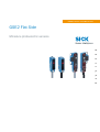 2
2
-
 3
3
-
 4
4
-
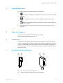 5
5
-
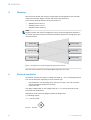 6
6
-
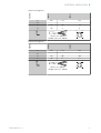 7
7
-
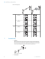 8
8
-
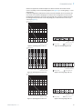 9
9
-
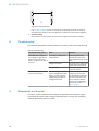 10
10
-
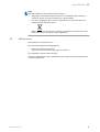 11
11
-
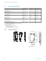 12
12
-
 13
13
-
 14
14
-
 15
15
-
 16
16
-
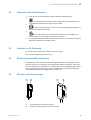 17
17
-
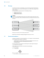 18
18
-
 19
19
-
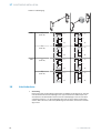 20
20
-
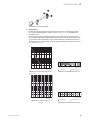 21
21
-
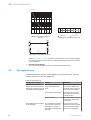 22
22
-
 23
23
-
 24
24
-
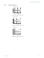 25
25
-
 26
26
-
 27
27
-
 28
28
-
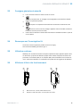 29
29
-
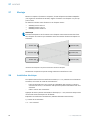 30
30
-
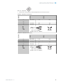 31
31
-
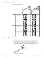 32
32
-
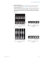 33
33
-
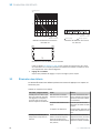 34
34
-
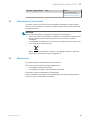 35
35
-
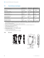 36
36
-
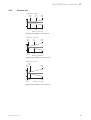 37
37
-
 38
38
-
 39
39
-
 40
40
-
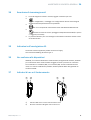 41
41
-
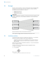 42
42
-
 43
43
-
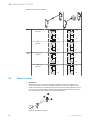 44
44
-
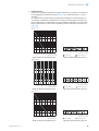 45
45
-
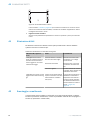 46
46
-
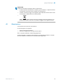 47
47
-
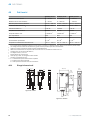 48
48
-
 49
49
-
 50
50
-
 51
51
-
 52
52
-
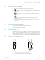 53
53
-
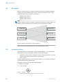 54
54
-
 55
55
-
 56
56
-
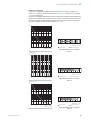 57
57
-
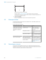 58
58
-
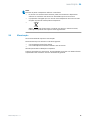 59
59
-
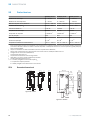 60
60
-
 61
61
-
 62
62
-
 63
63
-
 64
64
-
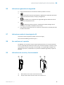 65
65
-
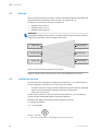 66
66
-
 67
67
-
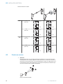 68
68
-
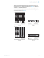 69
69
-
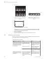 70
70
-
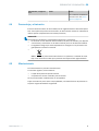 71
71
-
 72
72
-
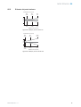 73
73
-
 74
74
-
 75
75
-
 76
76
-
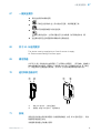 77
77
-
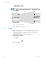 78
78
-
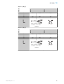 79
79
-
 80
80
-
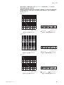 81
81
-
 82
82
-
 83
83
-
 84
84
-
 85
85
-
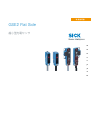 86
86
-
 87
87
-
 88
88
-
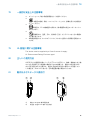 89
89
-
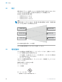 90
90
-
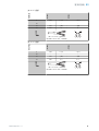 91
91
-
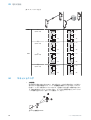 92
92
-
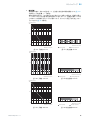 93
93
-
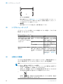 94
94
-
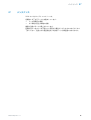 95
95
-
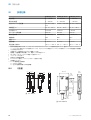 96
96
-
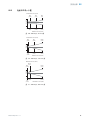 97
97
-
 98
98
-
 99
99
-
 100
100
-
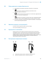 101
101
-
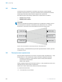 102
102
-
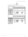 103
103
-
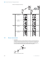 104
104
-
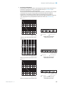 105
105
-
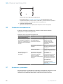 106
106
-
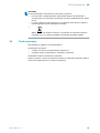 107
107
-
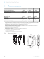 108
108
-
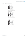 109
109
-
 110
110


SICK GSE2 Flat Side Miniature photoelectric sensors Instrucciones de operación
- Tipo
- Instrucciones de operación
en otros idiomas
- français: SICK GSE2 Flat Side Miniature photoelectric sensors Mode d'emploi
- italiano: SICK GSE2 Flat Side Miniature photoelectric sensors Istruzioni per l'uso
- English: SICK GSE2 Flat Side Miniature photoelectric sensors Operating instructions
- Deutsch: SICK GSE2 Flat Side Miniature photoelectric sensors Bedienungsanleitung
- русский: SICK GSE2 Flat Side Miniature photoelectric sensors Инструкция по эксплуатации
- português: SICK GSE2 Flat Side Miniature photoelectric sensors Instruções de operação
- 日本語: SICK GSE2 Flat Side Miniature photoelectric sensors 取扱説明書
Artículos relacionados
-
SICK GTB2 Flat Miniature photoelectric sensors Instrucciones de operación
-
-
-
SICK GSE6L Instrucciones de operación
-
-
-
-
-