
O P E R A T I N G I N S T R U C T I O N
GSE6L
Miniature photoelectric sensors


Described product
G6L
GSE6L
Manufacturer
SICK AG
Erwin-Sick-Str. 1
79183 Waldkirch
Germany
Production location
SICK Malaysia
Legal information
This work is protected by copyright. Any rights derived from the copyright shall be
reserved for SICK AG. Reproduction of this document or parts of this document is
only permissible within the limits of the legal determination of Copyright Law. Any modi‐
fication, abridgment or translation of this document is prohibited without the express
written permission of SICK AG.
The trademarks stated in this document are the property of their respective owner.
© SICK AG. All rights reserved.
Original document
This document is an original document of SICK AG.
Laser
1
2006/42/EC
NO
SAFETY
8025390.1AR6 / 21.02.2021 | SICK
Subject to change without notice
3

Contents
1 General safety notes......................................................................... 5
2 Notes on UL approval........................................................................ 5
3 Intended use...................................................................................... 5
4 Operating and status indicators...................................................... 6
5 Mounting............................................................................................. 6
6 Electrical installation........................................................................ 7
7 Commissioning.................................................................................. 9
7.1 Alignment.................................................................................................. 9
7.2 Sensing range........................................................................................... 9
7.3 Settings..................................................................................................... 10
8 Troubleshooting................................................................................. 10
9 Disassembly and disposal............................................................... 11
10 Maintenance...................................................................................... 11
11 Technical specifications................................................................... 12
11.1 Dimensional drawing................................................................................ 13
11.2 Light spot diagram.................................................................................... 13
CONTENTS
4
8025390.1AR6 / 21.02.2021 | SICK
Subject to change without notice

1 General safety notes
■
Read the operating instructions before commissioning.
■
Connection, mounting, and configuration may only be performed by trained
specialists.
■
2006/42/EC
NO
SAFETY
Not a safety component in accordance with the EU Machinery Directive.
■
Do not install the sensor at locations that are exposed to direct sunlight
or other weather influences, unless this is expressly permitted in the operating
instructions.
■
These operating instructions contain information required during the life cycle of
the sensor.
EN/IEC 60825-1:2014
IEC60825-1:2007
LASER CLASS 1
Laser
1
Maximum pulse power < 3.9 mW
Puls length: 3 µs
Wavelength: 670 - 690 nm
Complies with FDA performance
standards except for conformance with
IEC 60825-1 Ed. 3,
as described in Laser Notice No. 56,
dated May 8, 2019
ATTENTION
WARNING: Interruption, manipulation or incorrect use can lead to hazardous exposure
due to laser radiation.
2 Notes on UL approval
The device shall be supplied from an isolating transformer having a secondary overcur‐
rent protective device that complies with UL 248 to be installed in the field rated either:
a) max 5 amps for voltages 0 ~ 20 V (0 ~ 28.3 V peak), or
b) 100 / Vp for voltages of 20 ~ 30 V (28.3 ~ 42.4 V peak).
Alternatively, they can be supplied from a Class 2 power supply.
UL Environmental Rating: Enclosure type 1
3 Intended use
The GSE6L is an opto-electronic through-beam photoelectric sensor (referred to as
“sensor” in the following) for the optical, non-contact detection of objects. A sender
(GS) and a receiver (GE) are required for operation. If the product is used for any other
purpose or modified in any way, any warranty claim against SICK AG shall become void.
GENERAL SAFETY NOTES 1
8025390.1AR6 / 21.02.2021 | SICK
Subject to change without notice
5

4 Operating and status indicators
GSE6L-xxx1x
1
2 3
23
1
1
Potentiometer: sensitivity adjustment
2
LED indicator yellow: status of received light beam
3
LED indicator green: supply voltage active
GSE6L-xxx3x
Sensor which it is not possible to set: The sensor is adjusted and ready for operation.
2 3
23
5 Mounting
Mount sensors (sender and receiver) using suitable mounting brackets (see the SICK
range of accessories). Align the sender and receiver with each other.
4 OPERATING AND STATUS INDICATORS
6
8025390.1AR6 / 21.02.2021 | SICK
Subject to change without notice

NOTE
When mounting through beam photoelectric sensors adjacent to each other, alternate
the sender (GS6L) and receiver (GE6L) arrangement every other pair. Also ensure
that there is sufficient distance between pairs based on the sender (GS6L) light spot
diameter. Refer to figure 1 and figure 2.
Receiver (GE)
Receiver (GE)
Sender (GS)
Sender (GS)
Sender (GS)
Receiver (GE)
Figure 1: Arrangement of several through-beam photoelectric sensors
Sensor
Ø 70
(2.76)
Ø 3.5
(0.14)
Ø 90
(3.54)
Ø 120
(4.72)
Distance in m (feet)
Diameter in mm (inch)
1
(3.28)
12
(39.37)
30
(98.43)
40
(131.23)
Figure 2: GSE6L
6 Electrical installation
The sensors must be connected in a voltage-free state (U
V
= 0 V). The following informa‐
tion must be observed depending on the connection type:
– Plug connection: pin assignment
– Cable: wire color
Only apply voltage/switch on the voltage supply (U
V
> 0 V) once all electrical connec‐
tions have been established.
Explanation of connection terminology:
BN = Brown
WH = White
BU = Blue
BK = Black
n. c. = no connection
Q = switching output 1
Q = switching output 2
L+ = supply voltage (Uv)
M = common
L.ON = light operate
ELECTRICAL INSTALLATION 6
8025390.1AR6 / 21.02.2021 | SICK
Subject to change without notice
7

D.ON = dark operate
Connection and Output detail:
Table 1: DC
GE6L -P1xxx
-N1xxx
-E2xxx
-F2xxx
-P3xxx
-N3xxx
-P5xxx
-N5xxx
-P4xxx
-N4xxx
-P6xxx
-N6xxx
-P7xxx
-N7xxx
-E4xxx
-F4xxx
-E6xxx
-F6xxx
-E7xxx
-F7xxx
1 = BN + (L+) + (L+) + (L+) + (L+) + (L+)
2 = WH -
Q
- n. c.
Q
3 = BU - (M) - (M) - (M) - (M) - (M)
4 = BK Q Q Q Q Q
0.205 mm
2
/
AWG24
0.205 mm
2
/
AWG24
1
4
3
2
1
4
3
2
1
4
3
Table 2: DC, GS
GS6L- -D1xxx -D3xxx
-D5xxx
-D4xxx
-D6xxx
-D7xxx
-DAxxx
-DBxxx
-DCxxx
1 = BN + (L+) + (L+) + (L+)
2 = WH - - n. c.
3 = BU - (M) - (M) - (M)
4 = BK n. c. n. c. n. c.
0.205 mm
2
/ AWG24
1
4
3
2
1
4
3
Table 3: Output function
GE6L
-Px1xx
-Px2xx
-Px5xx
-Px6xx
L.ON, PNP: Q (≤ 100 mA)
+ (L+)
Q
‒ (M)
Load
+ (L+)
Q
‒ (M)
Load
6 ELECTRICAL INSTALLATION
8
8025390.1AR6 / 21.02.2021 | SICK
Subject to change without notice

-Px1xx
-Px2xx
-Px3xx
-Px4xx
D.ON, PNP: Q (≤ 100 mA)
+ (L+)
Q
‒ (M)
Load
+ (L+)
Q
‒ (M)
Load
-Nx1xx
-Nx2xx
-Nx5xx
-Nx6xx
L.ON, NPN Open Collector Q (≤ 100 mA)
+ (L+)
Q
‒ (M)
+ (L+)
Q
‒ (M)
Load
+ (L+)
Q
‒ (M)
Load
-Nx1xx
-Nx2xx
-Nx3xx
-Nx4xx
D.ON, NPN Open Collector Q (≤ 100 mA)
+ (L+)
Q
‒ (M)
Load
+ (L+)
Q
‒ (M)
+ (L+)
Q
‒ (M)
Load
7 Commissioning
7.1 Alignment
Align the sender with the receiver. Select the position so that the red emitted light beam
hits the receiver. Tip: Use white paper or a reflector as an alignment aid. The sender
must have a clear view of the receiver, with no object in the path of the beam [see
figure 3]. You must ensure that the optical openings (front screen) of the sensors are
completely clear.
Figure 3: Alignment
7.2 Sensing range
Observe the application conditions: Adjust the distance between the sender and the
receiver according to the corresponding diagram [see figure 4] (x = sensing range, y =
operating reserve).
When mounting through beam photoelectric sensors adjacent to each other, alternate
the sender (GS6L) and receiver (GE6L) arrangement every other pair. Also ensure
that there is sufficient distance between pairs based on the sender (GS6L) light spot
diameter. By doing this, mutual interference can be prevented [see figure 1].
Use table 3 to check the function. If the switching output fails to behave in accordance
with table 3, check the application conditions.
COMMISSIONING 7
8025390.1AR6 / 21.02.2021 | SICK
Subject to change without notice
9

100
10
1
Operating reserve
40
(131.23)
10
(32.80)
20
(65.62)
30
(98.43)
0
Distance in m (feet)
Recommended sensing range for
the best performance
Figure 4: Characteristic curve, GSE6L
7.3
Settings
Sensitivity setting
Sensor which it is not possible to set: The sensor is adjusted and ready for operation.
The sensitivity is adjusted with the potentiometer (type: 5-turn). Clockwise rotation:
operating reserve increased; counterclockwise rotation: operating reserve reduced. We
recommend setting the potentiometer to “Maximum”.
The sensor is adjusted and ready for operation.
8 Troubleshooting
The Troubleshooting table indicates measures to be taken if the sensor stops working.
Table 4: Troubleshooting
LED indicator/fault pattern Cause Measures
Yellow LED does not light up
even though the light beam
is aligned to the receiver and
there is no object in the path of
the beam
No voltage or voltage below
the limit values
Check the power supply,
check all electrical connec‐
tions (cables and plug connec‐
tions)
Voltage interruptions Ensure there is a stable power
supply without interruptions
Sensor is faulty If the power supply is OK,
replace the sensor
Yellow LED flashes Sensor is still ready for oper‐
ation, but the operating condi‐
tions are not ideal
Check the operating condi‐
tions: Fully align the beam
of light (light spot) with the
receiver. / Clean the optical
surfaces / If the potentiom‐
eter is set to the max. sen‐
sitivity: Reduce the distance
7 COMMISSIONING
10
8025390.1AR6 / 21.02.2021 | SICK
Subject to change without notice

LED indicator/fault pattern Cause Measures
between the sender and the
receiver / Check sensing
range and adjust if necessary
Yellow LED lights up, no object
in the path of the beam
The beam of light of a pho‐
toelectric through-beam sen‐
sor hits the receiver of
another (neighboring) photo‐
electric through-beam sensor
Swap the sender and receiver
arrangement at every sec‐
ond through-beam photoelec‐
tric sensor and ensure that
there is sufficient distance
between the through-beam
photoelectric sensors : see
figure 1, page 7
9 Disassembly and disposal
The sensor must be disposed of according to the applicable country-specific regula‐
tions. Efforts should be made during the disposal process to recycle the constituent
materials (particularly precious metals).
NOTE
Disposal of batteries, electric and electronic devices
•
According to international directives, batteries, accumulators and electrical or
electronic devices must not be disposed of in general waste.
•
The owner is obliged by law to return this devices at the end of their life to the
respective public collection points.
•
WEEE: This symbol on the product, its package or in this document,
indicates that a product is subject to these regulations.
10 Maintenance
SICK sensors are maintenance-free.
We recommend doing the following regularly:
•
Clean the external lens surfaces
•
Check the screw connections and plug-in connections
No modifications may be made to devices.
Subject to change without notice. Specified product properties and technical data are
not written guarantees.
DISASSEMBLY AND DISPOSAL 9
8025390.1AR6 / 21.02.2021 | SICK
Subject to change without notice
11

11 Technical specifications
GSE6L
Laser class 1
Sensing range 0 ... 30 m
Sensing range max. 0 ... 40 m
Light spot diameter/distance 3.5 mm / 1000 mm
Supply voltage U
B
DC 10 ... 30 V
1)
Output current I
max.
100 mA
2)
Switching frequency 1,000 Hz
3)
Max. response time 0.625 ms
4)
Enclosure rating IP67
Protection class III
Circuit protection A, C, D
5)
Ambient operating temperature -20 ... +50 °C
6)
1)
Limit values. U
B
connections reverse-polarity protected. Residual ripple max 5 V
PP
2)
As of U
B
> 24 V, a max. load current I
max.
= 50 mA is permitted.
3)
With light / dark ratio 1:1
4)
Signal transit time with resistive load
5)
A = U
B
-connections reverse polarity protected
C = Interference suppression
D = outputs overcurrent and short-circuit protected
6)
As of T
a
≥ 45 °C, a max. supply voltage U
B
= 24 V and a max. load current I
max.
= 50 mA is permitted.
11 TECHNICAL SPECIFICATIONS
12
8025390.1AR6 / 21.02.2021 | SICK
Subject to change without notice

11.1 Dimensional drawing
6.3
(0.25)
0.5
(0.02)
21
(0.83)
0.5
(0.02)
9.7
(0.38)
3
(0.12)
11.5
(0.45)
31.5 (1.24)
28.5 (1.12)
25.4 (1.00)
2.3
(0.09)
18.3
(0.72)
305 (12.01)
9.7
(0.38)
12
(0.47)
1
2
4
4
3
Figure 5: Dimensional drawing
1
Center of optical axis, sender
2
Center of optical axis, receiver
3
Operating and status indicators
4
M3 threaded mounting hole
11.2 Light spot diagram
Sensor
Ø 70
(2.76)
Ø 3.5
(0.14)
Ø 90
(3.54)
Ø 120
(4.72)
Distance in m (feet)
Diameter in mm (inch)
1
(3.28)
12
(39.37)
30
(98.43)
40
(131.23)
TECHNICAL SPECIFICATIONS 11
8025390.1AR6 / 21.02.2021 | SICK
Subject to change without notice
13


Beschriebenes Produkt
G6L
GSE6L
Hersteller
SICK AG
Erwin-Sick-Str. 1
79183 Waldkirch
Deutschland
Fertigungsstandort
SICK Malaysia
Rechtliche Hinweise
Dieses Werk ist urheberrechtlich geschützt. Die dadurch begründeten Rechte bleiben
bei der Firma SICK AG. Die Vervielfältigung des Werks oder von Teilen dieses Werks
ist nur in den Grenzen der gesetzlichen Bestimmungen des Urheberrechtsgesetzes
zulässig. Jede Änderung, Kürzung oder Übersetzung des Werks ohne ausdrückliche
schriftliche Zustimmung der Firma SICK AG ist untersagt.
Die in diesem Dokument genannten Marken sind Eigentum ihrer jeweiligen Inhaber.
© SICK AG. Alle Rechte vorbehalten.
Originaldokument
Dieses Dokument ist ein Originaldokument der SICK AG.
Laser
1
2006/42/EC
NO
SAFETY
8025390.1AR6 / 21.02.2021 | SICK
Subject to change without notice
15

Inhalt
12 Allgemeine Sicherheitshinweise..................................................... 17
13 Hinweise zur UL Zulassung.............................................................. 17
14 Bestimmungsgemäße Verwendung............................................... 17
15 Betriebs- und Statusanzeigen.......................................................... 18
16 Montage.............................................................................................. 18
17 Elektrische Installation..................................................................... 19
18 Inbetriebnahme................................................................................. 21
18.1 Ausrichtung............................................................................................... 21
18.2 Schaltabstand........................................................................................... 21
18.3 Einstellungen............................................................................................. 22
19 Störungsbehebung............................................................................ 22
20 Demontage und Entsorgung............................................................ 23
21 Wartung.............................................................................................. 23
22 Technische Daten.............................................................................. 24
22.1 Maßzeichnung........................................................................................... 25
22.2 Lichtfleckdiagramm.................................................................................. 25
INHALT
16
8025390.1AR6 / 21.02.2021 | SICK
Subject to change without notice

12 Allgemeine Sicherheitshinweise
■
Lesen Sie vor der Inbetriebnahme des Geräts die Betriebsanleitung.
■
Der Anschluss, die Montage und die Konfiguration des Geräts dürfen nur
von geschultem Fachpersonal vorgenommen werden.
■
2006/42/EC
NO
SAFETY
Bei diesem Gerät handelt es sich um kein sicherheitsgerichtetes Bauteil im
Sinne der EU-Maschinenrichtlinie.
■
Installieren Sie den Sensor nicht an Orten, die direkter Sonneneinstrahlung
oder sonstigen Wettereinflüssen ausgesetzt sind, ausser dies ist in der Betriebs‐
anleitung ausdrücklich erlaubt.
■
Die vorliegende Betriebsanleitung enthält Informationen, die während des Lebens‐
zyklus der Lichtschranke benötigt werden.
EN/IEC 60825-1:2014
IEC60825-1:2007
LASERKLASSE 1
Laser
1
Maximale Pulsleistung: < 3,9 mW
Impulsdauer: 3 µs
Wellenlänge: 670 - 690 nm
Entspricht den FDA
Leistungsstandards mit Ausnahme der
Konformität mit IEC 60825-1, Ed. 3
wie im Laserhinweis Nr. 56 vom
08.05.2019 beschrieben
ACHTUNG
WARNUNG: Eingriffe, Manipulation oder eine unsachgemäße Verwendung können zu
gefährlicher Exposition gegenüber Laserstrahlung führen.
13 Hinweise zur UL Zulassung
The device shall be supplied from an isolating transformer having a secondary overcur‐
rent protective device that complies with UL 248 to be installed in the field rated either:
a) max 5 amps for voltages 0 ~ 20 V (0 ~ 28.3 V peak), or
b) 100 / Vp for voltages of 20 ~ 30 V (28.3 ~ 42.4 V peak).
Alternatively, they can be supplied from a Class 2 power supply.
UL Environmental Rating: Enclosure type 1
14 Bestimmungsgemäße Verwendung
Die GSE6L ist eine optoelektronische Einweg-Lichtschranke (im Folgenden Sensor
genannt) und wird zum optischen, berührungslosen Erfassen von Sachen eingesetzt.
Zum Betrieb ist ein Sender (GS) und ein Empfänger (GE) erforderlich. Bei jeder anderen
Verwendung und bei Veränderungen am Produkt verfällt jeglicher Gewährleistungsan‐
spruch gegenüber der SICK AG.
ALLGEMEINE SICHERHEITSHINWEISE 12
8025390.1AR6 / 21.02.2021 | SICK
Subject to change without notice
17

15 Betriebs- und Statusanzeigen
GSE6L-xxx1x
1
2 3
23
1
1
Potentiometer: Einstellung der Empfindlichkeit
2
Anzeige-LED gelb: Status Lichtempfang
3
Anzeige-LED grün: Versorgungsspannung aktiv
GSE6L-xxx3x
Sensor ohne Einstellmöglichkeit: Sensor ist eingestellt und betriebsbereit.
2 3
23
16 Montage
Lichtschranken (Sender und Empfänger) unter Verwendung geeigneter Befestigungs‐
winkel montieren (siehe SICK-Zubehörpalette). Sender und Empfänger aneinander aus‐
richten.
15 BETRIEBS- UND STATUSANZEIGEN
18
8025390.1AR6 / 21.02.2021 | SICK
Subject to change without notice

HINWEIS
Bei Montage mehrerer Einweg-Lichtschranken nebeneinander die Anordnung des Sen‐
ders (GS6L) und Empfängers (GE6L) bei jedem zweiten Paar vertauschen. Außerdem
basierend auf dem Lichtfleckdurchmesser des Senders (GS6L) einen ausreichend gro‐
ßen Abstand zwischen den Paaren einhalten. Siehe Abbildung 6 und Abbildung 7.
Receiver (GE)
Receiver (GE)
Sender (GS)
Sender (GS)
Sender (GS)
Receiver (GE)
Abbildung 6: Anordnung mehrerer Einweg-Lichtschranken
Sensor
Ø 70Ø 3,5 Ø 90 Ø 120
Abstand in m
Durchmesser in mm
1 12 30 40
Abbildung 7: GSE6L
17 Elektrische Installation
Anschluss der Sensoren muss spannungsfrei (U
V
= 0 V) erfolgen. Je nach Anschlussart
sind die folgenden Informationen zu beachten:
– Steckeranschluss: Anschlussbelegung
– Leitung: Aderfarbe
Erst nach Anschluss aller elektrischen Verbindungen die Spannungsversorgung (U
V
> 0 V) anlegen bzw. einschalten.
Erläuterung der Anschlussterminologie:
BN = braun
WH = weiß
BU = blau
BK = schwarz
n. c. = unbeschaltet
Q = Schaltausgang 1
Q = Schaltausgang 2
L+ = Versorgungsspannung (Uv)
M = gemeinsam
L.ON = Hellauswertung
D.ON = Dunkelauswertung
ELEKTRISCHE INSTALLATION 17
8025390.1AR6 / 21.02.2021 | SICK
Subject to change without notice
19

Anschluss- und Ausgangsdetails:
Tabelle 5: DC
GE6L -P1xxx
-N1xxx
-E2xxx
-F2xxx
-P3xxx
-N3xxx
-P5xxx
-N5xxx
-P4xxx
-N4xxx
-P6xxx
-N6xxx
-P7xxx
-N7xxx
-E4xxx
-F4xxx
-E6xxx
-F6xxx
-E7xxx
-F7xxx
1 = BN + (L+) + (L+) + (L+) + (L+) + (L+)
2 = WH -
Q
- n. c.
Q
3 = BU - (M) - (M) - (M) - (M) - (M)
4 = BK Q Q Q Q Q
0,205 mm
2
/ AWG2
4
0,205 mm
2
/ AWG2
4
1
4
3
2
1
4
3
2
1
4
3
Tabelle 6: DC, GS
GS6L- -D1xxx -D3xxx
-D5xxx
-D4xxx
-D6xxx
-D7xxx
-DAxxx
-DBxxx
-DCxxx
1 = BN + (L+) + (L+) + (L+)
2 = WH - - n. c.
3 = BU - (M) - (M) - (M)
4 = BK n. c. n. c. n. c.
0.205 mm
2
/ AWG24
1
4
3
2
1
4
3
Tabelle 7: Output function
GE6L
-Px1xx
-Px2xx
-Px5xx
-Px6xx
L.ON, PNP: Q (≤ 100 mA)
+ (L+)
Q
‒ (M)
Load
+ (L+)
Q
‒ (M)
Load
17 ELEKTRISCHE INSTALLATION
20
8025390.1AR6 / 21.02.2021 | SICK
Subject to change without notice

-Px1xx
-Px2xx
-Px3xx
-Px4xx
D.ON, PNP: Q (≤ 100 mA)
+ (L+)
Q
‒ (M)
Load
+ (L+)
Q
‒ (M)
Load
-Nx1xx
-Nx2xx
-Nx5xx
-Nx6xx
L.ON, NPN Open Collector Q (≤ 100 mA)
+ (L+)
Q
‒ (M)
+ (L+)
Q
‒ (M)
Load
+ (L+)
Q
‒ (M)
Load
-Nx1xx
-Nx2xx
-Nx3xx
-Nx4xx
D.ON, NPN Open Collector Q (≤ 100 mA)
+ (L+)
Q
‒ (M)
Load
+ (L+)
Q
‒ (M)
+ (L+)
Q
‒ (M)
Load
18 Inbetriebnahme
18.1 Ausrichtung
Den Sender auf den Empfänger ausrichten. Die Position so wählen, dass der rote
Sendelichtstrahl den Empfänger trifft. Tipp: weißes Papier oder einen Reflektor als
Ausrichthilfe verwenden. Der Sender muss freie Sicht auf den Empfänger haben, ohne
Objekte im Strahlweg [siehe Abbildung 8]. Es muss sichergestellt werden, dass die
Optiköffnungen (Frontscheibe) der Sensoren komplett frei sind.
Abbildung 8: Ausrichtung
18.2 Schaltabstand
Die Einsatzbedingungen prüfen: den Abstand zwischen Sender und Empfänger gemäß
dem entsprechenden Diagramm anpassen [siehe Abbildung 9] (x = Schaltabstand, y =
Funktionsreserve).
Bei Montage mehrerer Einweg-Lichtschranken nebeneinander die Anordnung des Sen‐
ders (GS6L) und Empfängers (GE6L) bei jedem zweiten Paar vertauschen. Außerdem
basierend auf dem Lichtfleckdurchmesser des Senders (GS6L) einen ausreichend gro‐
ßen Abstand zwischen den Paaren einhalten. Auf diese Weise kann eine gegenseitige
Beeinflussung verhindert werden [siehe Abbildung 6].
INBETRIEBNAHME 18
8025390.1AR6 / 21.02.2021 | SICK
Subject to change without notice
21

Mithilfe von Tabelle 3 die Funktion überprüfen. Wenn sich der Schaltausgang nicht
entsprechend Tabelle 3 verhält, die Einsatzbedingungen prüfen.
100
10
1
Funktionsreserve
4010 20 300
Abstand in m
Empfohlener Schaltabstandsbereich für
beste Performance
Abbildung 9: Kennlinie, GSE6L
18.3
Einstellungen
Empfindlichkeitseinstellung
Sensor, der nicht eingestellt werden kann: Der Sensor ist justiert und betriebsbereit.
Die Empfindlichkeit wird mit dem Potentiometer eingestellt (Typ: 5 Drehungen). Dre‐
hung im Uhrzeigersinn: Funktionsreserve erhöht; Drehung gegen den Uhrzeigersinn:
Funktionsreserve verringert. Es wird empfohlen, das Potentiometer auf „Maximum“
einzustellen.
Der Sensor ist justiert und betriebsbereit.
19 Störungsbehebung
Tabelle Störungsbehebung zeigt, welche Maßnahmen durchzuführen sind, wenn die
Funktion des Sensors nicht mehr gegeben ist.
Tabelle 8: Fehlerbehebung
Anzeige-LED / Fehlerbild Ursache Maßnahme
gelbe LED leuchtet nicht,
obwohl der Lichtstrahl auf den
Empfänger ausgerichtet ist und
kein Objekt im Strahlengang ist
keine Spannung oder Span‐
nung unterhalb der Grenz‐
werte
Spannungsversorgung prüfen,
den gesamten elektrischen
Anschluss prüfen (Leitungen
und Steckerverbindungen)
Spannungsunterbrechungen Sicherstellen einer stabilen
Spannungsversorgung ohne
Unterbrechungen
Sensor ist defekt Wenn Spannungsversorgung
in Ordnung ist, dann Sensor
austauschen
18 INBETRIEBNAHME
22
8025390.1AR6 / 21.02.2021 | SICK
Subject to change without notice

Anzeige-LED / Fehlerbild Ursache Maßnahme
gelbe LED blinkt Sensor ist noch betriebsbe‐
reit, aber die Betriebsbedin‐
gungen sind nicht optimal
Betriebsbedingungen prüfen:
Lichtstrahl (Lichtfleck) voll‐
ständig auf den Empfän‐
ger ausrichten / Reinigung
der optischen Flächen /
falls Potentiometer auf max.
Empfindlichkeit eingestellt:
Abstand zwischen Sender
und Empfänger verringern /
Schaltabstand überprüfen
und ggf. anpassen.
gelbe LED leuchtet, kein Objekt
im Strahlengang
Der Lichtstrahl einer Ein‐
weg-Lichtschranke trifft auf
den Empfänger einer anderen
(benachbarten) Einweg-Licht‐
schranke
Bei jeder zweiten Ein‐
weg-Lichtschranke die Anord‐
nung von Sender und Empfän‐
ger tauschen, bzw. genügend
Abstand zwischen den Ein‐
weg-Lichtschranken einhalten:
siehe Abbildung 6, Seite 19
20 Demontage und Entsorgung
Die Lichtschranke muss entsprechend den geltenden länderspezifischen Vorschriften
entsorgt werden. Bei der Entsorgung sollte eine werkstoffliche Verwertung (insbeson‐
dere der Edelmetalle) angestrebt werden.
HINWEIS
Entsorgung von Batterien, Elektro- und Elektronikgeräten
•
Gemäß den internationalen Vorschriften dürfen Batterien, Akkus sowie Elektro-
und Elektronikgeräte nicht mit dem Hausmüll entsorgt werden.
•
Der Besitzer ist gesetzlich verpflichtet, diese Geräte am Ende ihrer Lebensdauer
bei den entsprechenden öffentlichen Sammelstellen abzugeben.
•
WEEE: Dieses Symbol auf dem Produkt, dessen Verpackung oder im
vorliegenden Dokument gibt an, dass ein Produkt den genannten Vorschriften
unterliegt.
21 Wartung
SICK-Sensoren sind wartungsfrei.
Wir empfehlen, in regelmäßigen Abständen
•
die optischen Grenzflächen zu reinigen
•
Verschraubungen und Steckverbindungen zu überprüfen
Veränderungen an Geräten dürfen nicht vorgenommen werden.
Irrtümer und Änderungen vorbehalten. Angegebene Produkteigenschaften und techni‐
sche Daten stellen keine Garantieerklärung dar.
DEMONTAGE UND ENTSORGUNG 20
8025390.1AR6 / 21.02.2021 | SICK
Subject to change without notice
23

22 Technische Daten
GSE6L
Laserklasse 1
Schaltabstand 0 ... 30 m
Schaltabstand max. 0 ... 40 m
Lichtfleckdurchmesser/Entfernung 3.5 mm / 1000 mm
Versorgungsspannung U
B
DC 10 ... 30 V
1)
Ausgangsstrom I
max.
100 mA
2)
Schaltfrequenz 1,000 Hz
3)
Ansprechzeit max. 0.625 ms
4)
Schutzart IP67
Schutzklasse III
Schutzschaltungen A, C, D
5)
Betriebsumgebungstemperatur -20 ... +50 °C
6)
1)
Grenzwerte. U
B
-Anschlüsse verpolsicher. Restwelligkeit max. 5 V
ss
2)
Ab U
B
> 24 V ist ein max. Ausgangsstrom I
max
= 50 mA zulässig.
3)
Mit Hell- / Dunkelverhältnis 1:1
4)
Signallaufzeit bei ohmscher Last
5)
A = U
B
-Anschlüsse verpolsicher
C = Störimpulsunterdrückung
D = Ausgänge überstrom- und kurzschlussfest
6)
Ab T
u
≥ 45 °C ist eine max. Versorgungsspannung U
B
= 24 V und ein max. Ausgangsstrom I
max
= 50 mA zulässig.
22 TECHNISCHE DATEN
24
8025390.1AR6 / 21.02.2021 | SICK
Subject to change without notice

22.1 Maßzeichnung
6,3
0,5
21
0,5
9,7
3
11,5
31,5
28,5
25,4
2,3
18,3
305
9,7
12
1
2
4
4
3
Abbildung 10: Maßzeichnung
1
Mitte Optikachse, Sender
2
Mitte Optikachse, Empfänger
3
Bedien- und Anzeigeelemente
4
Befestigungsgewinde M3
22.2 Lichtfleckdiagramm
Sensor
Ø 70Ø 3,5 Ø 90 Ø 120
Abstand in m
Durchmesser in mm
1 12 30 40
TECHNISCHE DATEN 22
8025390.1AR6 / 21.02.2021 | SICK
Subject to change without notice
25


Produit décrit
G6L
GSE6L
Fabricant
SICK AG
Erwin-Sick-Straße 1
79183 Waldkirch
Allemagne
Site de fabrication
SICK Malaisie
Remarques juridiques
Cet ouvrage est protégé par les droits d'auteur. Les droits établis restent dévolus à
la société SICK AG. La reproduction de l'ouvrage, même partielle, n'est autorisée que
dans le cadre légal prévu par la loi sur les droits d'auteur. Toute modification, tout
abrègement ou toute traduction de l'ouvrage est interdit sans l'accord écrit exprès de la
société SICK AG.
Les marques citées dans ce document sont la propriété de leurs détenteurs respectifs.
© SICK AG. Tous droits réservés.
Document original
Ce document est un document original de SICK AG.
Laser
1
2006/42/EC
NO
SAFETY
8025390.1AR6 / 21.02.2021 | SICK
Subject to change without notice
27

Contenu
23 Consignes générales de sécurité.................................................... 29
24 Remarques sur l’homologation UL................................................. 29
25 Utilisation conforme.......................................................................... 29
26 Afficheurs d’état et de fonctionnement......................................... 30
27 Montage.............................................................................................. 30
28 Installation électrique....................................................................... 31
29 Mise en service.................................................................................. 33
29.1 Alignement................................................................................................ 33
29.2 Distance de commutation........................................................................ 33
29.3 Réglages.................................................................................................... 34
30 Élimination des défauts................................................................... 34
31 Démontage et mise au rebut.......................................................... 35
32 Maintenance...................................................................................... 35
33 Caractéristiques techniques............................................................ 37
33.1 Plan coté.................................................................................................... 38
33.2 Schéma du spot lumineux........................................................................ 38
CONTENU
28
8025390.1AR6 / 21.02.2021 | SICK
Subject to change without notice

23 Consignes générales de sécurité
■
Lire la notice d’instruction avant la mise en service.
■
Le raccordement, le montage et la configuration ne doivent être réalisés
que par un personnel qualifié.
■
2006/42/EC
NO
SAFETY
N’est pas un composant de sécurité selon la Directive machines de l’UE.
■
N’installez pas le capteur à des endroits directement exposées aux rayons
du soleil ou à d’autres conditions météorologiques, sauf si cela est explicitement
autorisé dans la notice d'instruction.
■
Cette notice d’instruction contient des informations nécessaires durant le cycle de
vie du capteur.
EN/IEC 60825-1:2014
IEC60825-1:2007
LASER CLASS 1
Laser
1
Maximum pulse power < 3.9 mW
Puls length: 3 µs
Wavelength: 670 - 690 nm
Complies with FDA performance
standards except for conformance with
IEC 60825-1 Ed. 3,
as described in Laser Notice No. 56,
dated May 8, 2019
ATTENTION
ATTENTION : Toute intervention, manipulation ou utilisation non conforme peuvent
provoquer une exposition dangereuse aux rayons laser.
24 Remarques sur l’homologation UL
The device shall be supplied from an isolating transformer having a secondary overcur‐
rent protective device that complies with UL 248 to be installed in the field rated either:
a) max 5 amps for voltages 0 ~ 20 V (0 ~ 28.3 V peak), or
b) 100 / Vp for voltages of 20 ~ 30 V (28.3 ~ 42.4 V peak).
Alternatively, they can be supplied from a Class 2 power supply.
UL Environmental Rating: Enclosure type 1
25 Utilisation conforme
GSE6L est une barrière émetteur-récepteur optoélectronique (appelée capteur dans ce
document) qui permet la détection optique sans contact d’objets. Un émetteur (GS) et
un récepteur (GE) sont nécessaires à son fonctionnement. Toute autre utilisation ou
modification du produit annule la garantie de SICK AG.
CONSIGNES GÉNÉRALES DE SÉCURITÉ 23
8025390.1AR6 / 21.02.2021 | SICK
Subject to change without notice
29

26 Afficheurs d’état et de fonctionnement
GSE6L-xxx1x
1
2 3
23
1
1
Potentiomètre : réglage de la sensibilité
2
LED d’état jaune : état réception de lumière
3
LED d'état verte : tension d'alimentation active
GSE6L-xxx3x
Capteur sans possibilité de réglage : le capteur est réglé et prêt à l'emploi.
2 3
23
27 Montage
Monter les capteurs (émetteur et récepteur) à l’aide d’équerres de fixation adaptées
(voir la gamme d’accessoires de SICK). Aligner l’émetteur et le récepteur l’un par
rapport à l’autre.
26 AFFICHEURS D’ÉTAT ET DE FONCTIONNEMENT
30
8025390.1AR6 / 21.02.2021 | SICK
Subject to change without notice

REMARQUE
Lors du montage du faisceau capteurs photoélectriques les unes à côté des autres,
alterner le couple émetteur (GS6L) et récepteur (GE6L) à chaque paire. Également
s’assurer qu’il y ait suffisamment d’écart entre les paires basées sur le diamètre de
spot lumineux de l’émetteur (GS6L). Voir illustration 11 et illustration 12.
Receiver (GE)
Receiver (GE)
Sender (GS)
Sender (GS)
Sender (GS)
Receiver (GE)
Illustration 11: Disposition de plusieurs barrières émetteur-récepteur
Sensor
Ø 70
(2.76)
Ø 3.5
(0.14)
Ø 90
(3.54)
Ø 120
(4.72)
Distance in m (feet)
Diameter in mm (inch)
1
(3.28)
12
(39.37)
30
(98.43)
40
(131.23)
Illustration 12: GSE6L
28 Installation électrique
Les capteurs doivent être connectés hors tension (U
V
= 0 V). Observer les informations
suivantes, en fonction du mode de raccordement :
– Fiche de raccordement : affectation des broches
– Câble : couleur des conducteurs
Appliquer la tension/activer l’alimentation électrique (U
V
> 0 V) seulement lorsque tous
les raccordements électriques ont été établis.
Explication de la terminologie de raccordement :
BN = Marron
WH = Blanc
BU = Bleu
BK = Noir
n. c. = aucune connexion
Q = sortie de commutation 1
Q = sortie de commutation 2
L+ = tension d’alimentation (Uv)
M = commun
L.ON = commutation claire
INSTALLATION ÉLECTRIQUE 28
8025390.1AR6 / 21.02.2021 | SICK
Subject to change without notice
31

D.ON = commutation sombre
Détails sur la connexion et la sortie :
Tableau 9: CC
GE6L -P1xxx
-N1xxx
-E2xxx
-F2xxx
-P3xxx
-N3xxx
-P5xxx
-N5xxx
-P4xxx
-N4xxx
-P6xxx
-N6xxx
-P7xxx
-N7xxx
-E4xxx
-F4xxx
-E6xxx
-F6xxx
-E7xxx
-F7xxx
1 = BN (marron) + (L+) + (L+) + (L+) + (L+) + (L+)
2 = WH (blanc) -
Q
- n. c.
Q
3 = BU (bleu) - (M) - (M) - (M) - (M) - (M)
4 = BK (noir) Q Q Q Q Q
0,205 mm
2
/ AWG2
4
0,205 mm
2
/ AWG2
4
1
4
3
2
1
4
3
2
1
4
3
Tableau 10: DC, GS
GS6L- -D1xxx -D3xxx
-D5xxx
-D4xxx
-D6xxx
-D7xxx
-DAxxx
-DBxxx
-DCxxx
1 = BN + (L+) + (L+) + (L+)
2 = WH - - n. c.
3 = BU - (M) - (M) - (M)
4 = BK n. c. n. c. n. c.
0.205 mm
2
/ AWG24
1
4
3
2
1
4
3
Tableau 11: Output function
GE6L
28 INSTALLATION ÉLECTRIQUE
32
8025390.1AR6 / 21.02.2021 | SICK
Subject to change without notice

-Px1xx
-Px2xx
-Px5xx
-Px6xx
L.ON, PNP: Q (≤ 100 mA)
+ (L+)
Q
‒ (M)
Load
+ (L+)
Q
‒ (M)
Load
-Px1xx
-Px2xx
-Px3xx
-Px4xx
D.ON, PNP: Q (≤ 100 mA)
+ (L+)
Q
‒ (M)
Load
+ (L+)
Q
‒ (M)
Load
-Nx1xx
-Nx2xx
-Nx5xx
-Nx6xx
L.ON, NPN Open Collector Q (≤ 100 mA)
+ (L+)
Q
‒ (M)
+ (L+)
Q
‒ (M)
Load
+ (L+)
Q
‒ (M)
Load
-Nx1xx
-Nx2xx
-Nx3xx
-Nx4xx
D.ON, NPN Open Collector Q (≤ 100 mA)
+ (L+)
Q
‒ (M)
Load
+ (L+)
Q
‒ (M)
+ (L+)
Q
‒ (M)
Load
29 Mise en service
29.1 Alignement
Aligner l’émetteur avec le récepteur. Choisir la position de façon à ce que le faisceau
de lumière rouge émis rencontre le récepteur. Astuce : Utiliser du papier blanc ou un
réflecteur comme outil d'alignement. Aucun obstacle ne doit se trouver entre l’émetteur
et le récepteur, sur la trajectoire du faisceau [voir illustration 13]. Veiller à ce que les
ouvertures optiques (vitres frontales) des capteurs soient parfaitement dégagées.
Illustration 13: Alignement
29.2 Distance de commutation
Respecter les conditions d’application : ajuster la distance entre l’émetteur et le récep‐
teur selon le schéma correspondant [voir illustration 14] (x = distance de commutation,
y = réserve de fonctionnement).
MISE EN SERVICE 29
8025390.1AR6 / 21.02.2021 | SICK
Subject to change without notice
33

Lors du montage du faisceau capteurs photoélectriques les unes à côté des autres,
alterner le couple émetteur (GS6L) et récepteur (GE6L) à chaque paire. Également s’as‐
surer qu’il y ait suffisamment d’écart entre les paires basées sur le diamètre de spot
lumineux de l’émetteur (GS6L). Cette action peut empêcher l’interférence mutuelle
[voir illustration 11].
Utiliser tableau 3 pour contrôler le fonctionnement. Si la sortie de commutation ne se
comporte pas selon les indications de tableau 3, contrôler les conditions d’application.
100
10
1
Operating reserve
40
(131.23)
10
(32.80)
20
(65.62)
30
(98.43)
0
Distance in m (feet)
Recommended sensing range for
the best performance
Illustration 14: Courbe caractéristique, GSE6L
29.3
Réglages
Réglage de la sensibilité
Un capteur qui ne peut pas être déterminé : Le capteur est réglé et prêt à fonctionner.
La sensibilité est réglée avec le potentiomètre (type : 5 tours). Rotation dans le sens
des aiguilles d’une montre : réserve de fonctionnement accrue ; rotation dans le
sens inverse des aiguilles d’une montre : réserve de fonctionnement réduite. Nous
conseillons de régler le potentiomètre sur « Maximum ».
Le capteur est réglé et prêt à fonctionner.
30 Élimination des défauts
Le tableau Élimination des défauts présente les mesures à appliquer si le capteur ne
fonctionne plus.
Tableau 12: Suppression des défauts
LED d'état / image du défaut Cause Mesure
La LED jaune ne s’allume pas,
bien que le faisceau lumineux
soit aligné sur le récepteur et
qu’aucun objet ne se trouve
dans la trajectoire du faisceau
Pas de tension ou tension
inférieure aux valeurs limites
Contrôler l'alimentation élec‐
trique, contrôler tous les bran‐
chements électriques (câbles
et connexions)
29 MISE EN SERVICE
34
8025390.1AR6 / 21.02.2021 | SICK
Subject to change without notice

LED d'état / image du défaut Cause Mesure
Coupures d'alimentation élec‐
trique
S'assurer que l'alimentation
électrique est stable et ininter‐
rompue
Le capteur est défectueux Si l'alimentation électrique est
en bon état, remplacer le cap‐
teur
La LED jaune clignote Le capteur est encore opéra‐
tionnel, mais les conditions
d'utilisation ne sont pas idéa‐
les
Vérifier les conditions d’utili‐
sation : Diriger le faisceau
lumineux (spot lumineux)
entièrement sur le récepteur /
Nettoyage des surfaces opti‐
ques / Si le potentiomètre
est réglé sur la sensibilité
max. : réduire la distance
entre l’émetteur et le récep‐
teur / Contrôler la distance
de commutation et éventuelle‐
ment l’adapter
La LED jaune s'allume, pas
d'objet dans la trajectoire du
faisceau
Le faisceau lumineux d'une
barrière émetteur-récepteur
atteint le récepteur d'une
autre barrière émetteur-récep‐
teur (voisine)
Pour une barrière émet‐
teur-récepteur sur deux, inter‐
vertir la place de l’émetteur
et du récepteur ou laisser suf‐
fisamment d’espace entre les
barrières émetteur-récepteur :
voir illustration 11, page 31
31 Démontage et mise au rebut
Le capteur doit être mis au rebut selon les régulations spécifiques au pays respectif.
Dans la limite du possible, les matériaux du capteur doivent être recyclés (notamment
les métaux précieux).
REMARQUE
Mise au rebut des batteries, des appareils électriques et électroniques
•
Selon les directives internationales, les batteries, accumulateurs et appareils
électriques et électroniques ne doivent pas être mis au rebut avec les ordures
ménagères.
•
Le propriétaire est obligé par la loi de retourner ces appareils à la fin de leur cycle
de vie au point de collecte respectif.
•
WEEE: Ce symbole sur le produit, son emballage ou dans ce document
indique qu’un produit est soumis à ces régulations.
32 Maintenance
Les capteurs SICK ne nécessitent aucune maintenance.
Nous vous recommandons de procéder régulièrement
•
au nettoyage des surfaces optiques
•
au contrôle des vissages et des connexions enfichables
Ne procéder à aucune modification sur les appareils.
DÉMONTAGE ET MISE AU REBUT 31
8025390.1AR6 / 21.02.2021 | SICK
Subject to change without notice
35

Sujet à modification sans préavis. Les caractéristiques du produit et techniques four‐
nies ne sont pas une déclaration de garantie.
36
8025390.1AR6 / 21.02.2021 | SICK
Subject to change without notice

33 Caractéristiques techniques
GSE6L
Classe laser 1
Distance de commutation 0 ... 30 m
Portée max. 0 ... 40 m
Diamètre spot / distance 3.5 mm / 1000 mm
Tension d'alimentation U
B
DC 10 ... 30 V
1)
Courant de sortie I
max.
100 mA
2)
Fréquence de commutation 1,000 Hz
3)
Temps de réponse max. 0.625 ms
4)
Indice de protection IP67
Classe de protection III
Protections électriques A, C, D
5)
Température de service -20 ... +50 °C
6)
1)
Valeurs limites. Connexions U
B
protégées contre l’inversion de polarité Ondulation résiduelle max. 5 V
ss
2)
À partir de U
B
> 24 V un courant de sortie max. I
max
= 50 mA est admissible.
3)
Pour un rapport clair/sombre de 1:1
4)
Temps de propagation du signal sur charge ohmique
5)
A = raccordements U
B
protégés contre les inversions de polarité
C = Suppression des impulsions parasites
D = sorties protégées contre les courts-circuits et les surcharges
6)
À partir de T
u
≥ 45 °C, une tension d'alimentation U
B
= 24 V et un courant de sortie max. I
max
= 50 mA sont admissibles.
CARACTÉRISTIQUES TECHNIQUES 33
8025390.1AR6 / 21.02.2021 | SICK
Subject to change without notice
37

33.1 Plan coté
6.3
(0.25)
0.5
(0.02)
21
(0.83)
0.5
(0.02)
9.7
(0.38)
3
(0.12)
11.5
(0.45)
31.5 (1.24)
28.5 (1.12)
25.4 (1.00)
2.3
(0.09)
18.3
(0.72)
305 (12.01)
9.7
(0.38)
12
(0.47)
1
2
4
4
3
Illustration 15: Plan coté
1
Centre de l’axe optique émetteur
2
Centre de l’axe optique récepteur
3
Éléments de commande et d'affichage
4
Taraudage M3
33.2 Schéma du spot lumineux
Sensor
Ø 70
(2.76)
Ø 3.5
(0.14)
Ø 90
(3.54)
Ø 120
(4.72)
Distance in m (feet)
Diameter in mm (inch)
1
(3.28)
12
(39.37)
30
(98.43)
40
(131.23)
33 CARACTÉRISTIQUES TECHNIQUES
38
8025390.1AR6 / 21.02.2021 | SICK
Subject to change without notice


Produto descrito
G6L
GSE6L
Fabricante
SICK AG
Erwin-Sick-Str. 1
79183 Waldkirch
Alemanha
Local de fabricação
SICK Malaysia
Notas legais
Reservados os direitos autorais do presente documento. Todos os direitos permane‐
cem em propriedade da empresa SICK AG. A reprodução total ou parcial desta obra só
é permitida dentro dos limites regulamentados pela Lei de Direitos Autorais. É proibido
alterar, resumir ou traduzir esta obra sem a autorização expressa e por escrito da SICK
AG.
As marcas citadas neste documento são de propriedade de seus respectivos proprietá‐
rios.
© SICK AG. Todos os direitos reservados
Documento original
Este é um documento original da SICK AG.
Laser
1
2006/42/EC
NO
SAFETY
40
8025390.1AR6 / 21.02.2021 | SICK
Subject to change without notice

Índice
34 Instruções gerais de segurança...................................................... 42
35 Indicações sobre a homologação UL............................................. 42
36 Especificações de uso...................................................................... 42
37 Indicadores de operação e status................................................... 43
38 Montagem.......................................................................................... 43
39 Instalação elétrica............................................................................. 44
40 Colocação em operação.................................................................. 46
40.1 Alinhamento.............................................................................................. 46
40.2 Distância de comutação.......................................................................... 46
40.3 Configurações........................................................................................... 47
41 Eliminação de falhas........................................................................ 47
42 Desmontagem e descarte............................................................... 48
43 Manutenção....................................................................................... 48
44 Dados técnicos.................................................................................. 49
44.1 Desenho dimensional.............................................................................. 50
44.2 Diagrama do ponto de luz........................................................................ 50
ÍNDICE
8025390.1AR6 / 21.02.2021 | SICK
Subject to change without notice
41

34 Instruções gerais de segurança
■
Leia o Manual de instruções antes de colocar em operação.
■
A conexão, montagem e configuração podem ser efetuadas apenas por
técnicos especializados treinados.
■
2006/42/EC
NO
SAFETY
Este não é um componente de segurança em conformidade com a diretriz
de Máquinas da UE.
■
Não instalar o sensor em locais expostos à luz solar direta ou outras influ‐
ências atmosféricas, a menos que isto seja expressamente permitido no manual
de operação.
■
Este Manual de instruções contém as informações necessárias para operação
durante a vida útil do sensor.
EN/IEC 60825-1:2014
IEC60825-1:2007
LASER CLASS 1
Laser
1
Maximum pulse power < 3.9 mW
Puls length: 3 µs
Wavelength: 670 - 690 nm
Complies with FDA performance
standards except for conformance with
IEC 60825-1 Ed. 3,
as described in Laser Notice No. 56,
dated May 8, 2019
ATENÇÃO
AVISO: A interrupção, manipulação ou uso incorreto podem levar à exposição perigosa
devido à radiação laser.
35 Indicações sobre a homologação UL
The device shall be supplied from an isolating transformer having a secondary overcur‐
rent protective device that complies with UL 248 to be installed in the field rated either:
a) max 5 amps for voltages 0 ~ 20 V (0 ~ 28.3 V peak), or
b) 100 / Vp for voltages of 20 ~ 30 V (28.3 ~ 42.4 V peak).
Alternatively, they can be supplied from a Class 2 power supply.
UL Environmental Rating: Enclosure type 1
36 Especificações de uso
O GSE6L é uma barreira de luz unidirecional optoeletrônica (doravante denominada
“sensor”) utilizada para a detecção óptica e sem contato de objetos. Para a operação,
são necessários um emissor (GS) e um receptor (GE). Qualquer utilização diferente ou
alterações do produto ocasionam a perda da garantia da SICK AG.
34 INSTRUÇÕES GERAIS DE SEGURANÇA
42
8025390.1AR6 / 21.02.2021 | SICK
Subject to change without notice

37 Indicadores de operação e status
.
GSE6L-xxx1x
1
2 3
23
1
1
Potenciômetro: ajuste da sensibilidade
2
Indicador LED amarelo: status recepção luminosa
3
LED indicador, verde: tensão de alimentação ativa
GSE6L-xxx3x
Sensor, o qual não é possível definir: o sensor está ajustado e pronto para a operação.
2 3
23
38 Montagem
Monte os sensores (emissor e receptor) utilizando cantoneiras de fixação adequadas
(consulte a linha de acessórios SICK). Alinhe o emissor e o receptor um com o outro.
INDICADORES DE OPERAÇÃO E STATUS 37
8025390.1AR6 / 21.02.2021 | SICK
Subject to change without notice
43

NOTA
Para a montagem de barreiras de luz unidirecional adjacentes entre si, alterne o
arranjo do emissor (GS6L) e receptor (GE6L) a cada dois pares. Também assegure uma
distância suficiente entre os pares com base no diâmetro do ponto de luz do emissor
(GS6L). Consulte figura 16 e figura 17.
Receiver (GE)
Receiver (GE)
Sender (GS)
Sender (GS)
Sender (GS)
Receiver (GE)
Figura 16: Arranjo de várias barreiras de luz unidirecional
Sensor
Ø 70
(2.76)
Ø 3.5
(0.14)
Ø 90
(3.54)
Ø 120
(4.72)
Distance in m (feet)
Diameter in mm (inch)
1
(3.28)
12
(39.37)
30
(98.43)
40
(131.23)
Figura 17: GSE6L
39 Instalação elétrica
Os sensores devem ser conectados em estado desenergizado (U
V
= 0 V). As seguintes
informações devem ser observadas, dependendo do tipo de conexão:
– Conexão de encaixe: pinagem
– Cabo: cor do fio
Somente aplique tensão/ligue a alimentação de tensão (U
V
> 0 V) depois que todas as
conexões elétricas foram estabelecidas.
Explicação da terminologia de conexão:
BN = marrom
WH = branco
BU = azul
BK = preto
n. c. = sem conexão
Q = saída de comutação 1
Q = saída de comutação 2
L+ = tensão de alimentação (Uv)
M = comum
L.ON = operação por luz
39 INSTALAÇÃO ELÉTRICA
44
8025390.1AR6 / 21.02.2021 | SICK
Subject to change without notice

D.ON = operação por sombra
Detalhes de conexão e saída:
Tabela 13: DC
GE6L -P1xxx
-N1xxx
-E2xxx
-F2xxx
-P3xxx
-N3xxx
-P5xxx
-N5xxx
-P4xxx
-N4xxx
-P6xxx
-N6xxx
-P7xxx
-N7xxx
-E4xxx
-F4xxx
-E6xxx
-F6xxx
-E7xxx
-F7xxx
1 = BN + (L+) + (L+) + (L+) + (L+) + (L+)
2 = WH -
Q
- n. c.
Q
3 = BU - (M) - (M) - (M) - (M) - (M)
4 = BK Q Q Q Q Q
0,205 mm
2
/ AWG2
4
0,205 mm
2
/ AWG2
4
1
4
3
2
1
4
3
2
1
4
3
Tabela 14: DC, GS
GS6L- -D1xxx -D3xxx
-D5xxx
-D4xxx
-D6xxx
-D7xxx
-DAxxx
-DBxxx
-DCxxx
1 = BN + (L+) + (L+) + (L+)
2 = WH - - n. c.
3 = BU - (M) - (M) - (M)
4 = BK n. c. n. c. n. c.
0.205 mm
2
/ AWG24
1
4
3
2
1
4
3
Tabela 15: Output function
GE6L
INSTALAÇÃO ELÉTRICA 39
8025390.1AR6 / 21.02.2021 | SICK
Subject to change without notice
45

-Px1xx
-Px2xx
-Px5xx
-Px6xx
L.ON, PNP: Q (≤ 100 mA)
+ (L+)
Q
‒ (M)
Load
+ (L+)
Q
‒ (M)
Load
-Px1xx
-Px2xx
-Px3xx
-Px4xx
D.ON, PNP: Q (≤ 100 mA)
+ (L+)
Q
‒ (M)
Load
+ (L+)
Q
‒ (M)
Load
-Nx1xx
-Nx2xx
-Nx5xx
-Nx6xx
L.ON, NPN Open Collector Q (≤ 100 mA)
+ (L+)
Q
‒ (M)
+ (L+)
Q
‒ (M)
Load
+ (L+)
Q
‒ (M)
Load
-Nx1xx
-Nx2xx
-Nx3xx
-Nx4xx
D.ON, NPN Open Collector Q (≤ 100 mA)
+ (L+)
Q
‒ (M)
Load
+ (L+)
Q
‒ (M)
+ (L+)
Q
‒ (M)
Load
40 Colocação em operação
40.1 Alinhamento
Alinhe o emissor com o receptor. Selecione a posição de forma que o jato de luz verme‐
lha emitido atinja o receptor. Dica: Use um papel branco ou um refletor para auxiliar
no alinhamento. O emissor deve ter uma visão desimpedida do receptor, não devendo
haver objetos no caminho do jato [consulte figura 18]. Você deve garantir que as
aberturas ópticas (vidro frontal) dos sensores estejam completamente desimpedidas.
Figura 18: Alinhamento
40.2 Distância de comutação
Observe as condições da aplicação: ajuste a distância entre o sensor e o receptor
de acordo com o diagrama correspondente [consulte figura 19] (x = distância de
comutação, y = reserva operacional).
40 COLOCAÇÃO EM OPERAÇÃO
46
8025390.1AR6 / 21.02.2021 | SICK
Subject to change without notice

Para a montagem de barreiras de luz unidirecional adjacentes entre si, alterne o
arranjo do emissor (GS6L) e receptor (GE6L) a cada dois pares. Também assegure uma
distância suficiente entre os pares com base no diâmetro do ponto de luz do emissor
(GS6L). Isso evita que haja interferência mútua [consulte figura 16].
Use tabela 3 para verificar a função. Se a saída de comutação não se comportar
conforme a tabela 3, verifique as condições da aplicação.
100
10
1
Operating reserve
40
(131.23)
10
(32.80)
20
(65.62)
30
(98.43)
0
Distance in m (feet)
Recommended sensing range for
the best performance
Figura 19: Curva característica, GSE6L
40.3
Configurações
Configuração de sensibilidade
Sensor, o qual não é possível definir: o sensor está ajustado e pronto para a operação.
A sensibilidade é ajustada com o potenciômetro (tipo: 5 voltas). Rotação no sentido
horário: aumento na reserva operacional; rotação no sentido anti-horário: redução na
reserva operacional. Recomendamos configurar o potenciômetro no “Máximo”.
O sensor está ajustado e pronto para a operação.
41 Eliminação de falhas
A tabela Eliminação de falhas mostra as medidas a serem executadas, quando o
sensor não estiver funcionando.
Tabela 16: Resolução de problemas
Indicador LED / padrão de erro Causa Medida
O LED amarelo não está aceso,
embora o feixe de luz esteja
alinhado sobre o receptor e
não haja objeto no caminho do
feixe
Sem tensão ou tensão abaixo
dos valores-limite
Verificar a alimentação de ten‐
são, verificar toda a conexão
elétrica (cabos e conectores)
Interrupções de tensão Assegurar uma alimentação
de tensão estável sem inter‐
rupções
COLOCAÇÃO EM OPERAÇÃO 40
8025390.1AR6 / 21.02.2021 | SICK
Subject to change without notice
47

Indicador LED / padrão de erro Causa Medida
Sensor está com defeito Se a alimentação de tensão
estiver em ordem, substituir o
sensor
LED amarelo intermitente Sensor ainda está operacio‐
nal, mas as condições de ope‐
ração não são ideais
Verificar as condições de ope‐
ração: Alinhar o feixe de
luz (ponto de luz) completa‐
mente ao receptor / Limpeza
das superfícies ópticas / Se
o potenciômetro estiver ajus‐
tado para a máx. sensibili‐
dade: reduzir a distância entre
o emissor e o receptor / Verifi‐
car e, se necessário, adaptar
a distância de comutação
LED amarelo aceso, nenhum
objeto no caminho óptico
O feixe de luz de uma bar‐
reira de luz unidirecional está
incidindo sobre o receptor de
uma outra barreira de luz uni‐
direcional (vizinha)
Trocar a disposição do sensor
e do receptor a cada duas
barreiras de luz unidirecionais
ou manter distância suficiente
entre as barreira de luz uni‐
direcionais: ver figura 16,
página 44
42 Desmontagem e descarte
O sensor deve ser descartado de acordo com os regulamentos específicos por país
aplicáveis. Deve-se realizar um esforço durante o processo de descarte para reciclar os
materiais constituintes (particularmente metais preciosos).
NOTA
Descarte de pilhas e dispositivos elétricos e eletrônicos
•
De acordo com diretrizes internacionais, pilhas, acumuladores e dispositivos elé‐
tricos ou eletrônicos não devem ser descartados junto do lixo comum.
•
O proprietário é obrigado por lei a retornar esses dispositivos ao fim de sua vida
útil para os pontos de coleta públicos respectivos.
•
WEEE: Este símbolo sobre o produto, seu pacote o neste documento,
indica que um produto está sujeito a esses regulamentos.
43 Manutenção
Os sensores SICK não requerem manutenção.
Recomendamos que se efetue em intervalos regulares
•
uma limpeza das superfícies ópticas
•
uma verificação das conexões roscadas e dos conectores
Não são permitidas modificações no aparelho.
Sujeito a alterações sem aviso prévio. As propriedades do produto e os dados técnicos
especificados não constituem nenhum certificado de garantia.
42 DESMONTAGEM E DESCARTE
48
8025390.1AR6 / 21.02.2021 | SICK
Subject to change without notice

44 Dados técnicos
GSE6L
Classe de laser 1
Distância de comutação 0 ... 30 m
Distância de comutação máx. 0 ... 40 m
Diâmetro do ponto de luz/distância 3.5 mm / 1000 mm
Tensão de alimentação U
B
DC 10 ... 30 V
1)
Corrente de saída I
max.
100 mA
2)
Frequência de comutação 1,000 Hz
3)
Tempo máx. de resposta 0.625 ms
4)
Tipo de proteção IP67
Classe de proteção III
Circuitos de proteção A, C, D
5)
Temperatura ambiente de funcionamento -20 ... +50 °C
6)
1)
Valores-limite. Conexões U
B
protegidas contra inversão de polaridade. Ondulação residual máx. 5 V
ss
2)
A partir de uma U
B
> 24 V é permitida uma corrente máxima de saída I
max
= 50 mA.
3)
Com proporção sombra/luz 1:1
4)
Tempo de funcionamento do sinal com carga ôhmica
5)
A = conexões protegidas contra inversão de pólos U
B
C = Supressão de impulsos parasitas
D = Saídas protegidas contra sobrecorrente e curto-circuito
6)
A partir de uma T
u
≥ 45 °C é permitida uma tensão de alimentação máx. U
B
= 24 V e uma corrente máxima de saída I
max
= 50 mA.
DADOS TÉCNICOS 44
8025390.1AR6 / 21.02.2021 | SICK
Subject to change without notice
49

44.1 Desenho dimensional
6.3
(0.25)
0.5
(0.02)
21
(0.83)
0.5
(0.02)
9.7
(0.38)
3
(0.12)
11.5
(0.45)
31.5 (1.24)
28.5 (1.12)
25.4 (1.00)
2.3
(0.09)
18.3
(0.72)
305 (12.01)
9.7
(0.38)
12
(0.47)
1
2
4
4
3
Figura 20: Desenho dimensional
1
Centro do eixo do sistema óptico, emissor
2
Centro do eixo do sistema óptico receptor
3
Elementos de comando e indicação
4
Rosca de fixação M3
44.2 Diagrama do ponto de luz
Sensor
Ø 70
(2.76)
Ø 3.5
(0.14)
Ø 90
(3.54)
Ø 120
(4.72)
Distance in m (feet)
Diameter in mm (inch)
1
(3.28)
12
(39.37)
30
(98.43)
40
(131.23)
44 DADOS TÉCNICOS
50
8025390.1AR6 / 21.02.2021 | SICK
Subject to change without notice


Descrizione prodotto
G6L
GSE6L
Produttore
SICK AG
Erwin-Sick-Str. 1
79183 Waldkirch
Germania
Luogo di produzione
SICK Malesia
Note legali
Questo manuale è protetto dai diritti d'autore. I diritti che ne conseguono rimangono
alla ditta SICK. Il manuale o parti di esso possono essere fotocopiati esclusivamente
entro i limiti previsti dalle disposizioni di legge in materia di diritti d’autore. Non è
consentito modificare, abbreviare o tradurre il presente manuale senza previa autoriz‐
zazione scritta della ditta SICK AG.
I marchi riportati nel presente manuale sono di proprietà del rispettivo proprietario.
© SICK AG. Tutti i diritti riservati.
Documento originale
Questo documento è un originale della ditta SICK AG.
Laser
1
2006/42/EC
NO
SAFETY
52
8025390.1AR6 / 21.02.2021 | SICK
Subject to change without notice

Indice
45 Avvertenze di sicurezza generali..................................................... 54
46 Indicazioni sull’omologazione UL.................................................... 54
47 Uso conforme alle disposizioni........................................................ 54
48 Indicatori di uso e di funzionamento.............................................. 55
49 Montaggio.......................................................................................... 55
50 Installazione elettrica....................................................................... 56
51 Messa in funzione............................................................................. 58
51.1 Allineamento............................................................................................. 58
51.2 Distanza di lavoro..................................................................................... 58
51.3 Impostazioni.............................................................................................. 59
52 Eliminazione difetti........................................................................... 59
53 Smontaggio e smaltimento............................................................. 60
54 Manutenzione.................................................................................... 60
55 Dati tecnici.......................................................................................... 61
55.1 Disegni dimensionali................................................................................ 62
55.2 Diagramma del punto luminoso.............................................................. 62
INDICE
8025390.1AR6 / 21.02.2021 | SICK
Subject to change without notice
53

45 Avvertenze di sicurezza generali
■
Prima di eseguire la messa in servizio, leggere le istruzioni per l’uso.
■
Il collegamento, il montaggio e la configurazione devono essere eseguiti
esclusivamente da personale tecnico qualificato.
■
2006/42/EC
NO
SAFETY
Non è un componente di sicurezza ai sensi della Direttiva Macchine UE.
■
Non installare il sensore in luoghi esposti all'irraggiamento solare diretto
o ad altri influssi meteorologici, se non espressamente consentito nelle istruzioni
per l'uso.
■
Le presenti Istruzioni per l’uso contengono informazioni necessarie durante il ciclo
di vita del sensore.
EN/IEC 60825-1:2014
IEC60825-1:2007
LASER CLASS 1
Laser
1
Maximum pulse power < 3.9 mW
Puls length: 3 µs
Wavelength: 670 - 690 nm
Complies with FDA performance
standards except for conformance with
IEC 60825-1 Ed. 3,
as described in Laser Notice No. 56,
dated May 8, 2019
ATTENZIONE
ATTENZIONE: l’interruzione, la manipolazione o l’uso improprio possono causare un’e‐
sposizione pericolosa dovuta a radiazioni laser.
46 Indicazioni sull’omologazione UL
The device shall be supplied from an isolating transformer having a secondary overcur‐
rent protective device that complies with UL 248 to be installed in the field rated either:
a) max 5 amps for voltages 0 ~ 20 V (0 ~ 28.3 V peak), or
b) 100 / Vp for voltages of 20 ~ 30 V (28.3 ~ 42.4 V peak).
Alternatively, they can be supplied from a Class 2 power supply.
UL Environmental Rating: Enclosure type 1
47 Uso conforme alle disposizioni
GSE6L è un sensore fotoelettrico a sbarramento (di seguito detto sensore) utilizzato
per il rilevamento ottico senza contatto di oggetti. Per l’esercizio sono necessari un
emettitore (GS) e un ricevitore (GE). Se viene utilizzato diversamente e in caso di
modifiche del prodotto, decade qualsiasi diritto alla garanzia nei confronti di SICK.
45 AVVERTENZE DI SICUREZZA GENERALI
54
8025390.1AR6 / 21.02.2021 | SICK
Subject to change without notice

48 Indicatori di uso e di funzionamento
GSE6L-xxx1x
1
2 3
23
1
1
Potenziometro: impostazione della sensibilità
2
Indicatore LED giallo: stato ricezione luce
3
Indicatore LED verde: tensione di alimentazione attiva
GSE6L-xxx3x
Sensore senza possibilità di impostazione: il sensore è impostato e pronto per il funzio‐
namento.
2 3
23
49 Montaggio
Montare il sensore (emettitore e ricevitore) utilizzando delle staffe di fissaggio adatte
(vedi la gamma di accessori SICK). Allineare l’emettitore e il ricevitore fra di loro.
INDICATORI DI USO E DI FUNZIONAMENTO 48
8025390.1AR6 / 21.02.2021 | SICK
Subject to change without notice
55

INDICAZIONE
Se i sensori fotoelettrici a sbarramento vengono montati l’uno accanto all’altro, alter‐
nare la disposizione di emettitore (GS6L) e ricevitore (GE6L) ad ogni coppia. Assicurare
inoltre una distanza sufficiente tra le coppie in base al diametro del punto luminoso
dell’emettitore (GS6L). Consultare figura 21 e figura 22.
Receiver (GE)
Receiver (GE)
Sender (GS)
Sender (GS)
Sender (GS)
Receiver (GE)
Figura 21: Disposizione di diversi sensori fotoelettrici a sbarramento
Sensor
Ø 70
(2.76)
Ø 3.5
(0.14)
Ø 90
(3.54)
Ø 120
(4.72)
Distance in m (feet)
Diameter in mm (inch)
1
(3.28)
12
(39.37)
30
(98.43)
40
(131.23)
Figura 22: GSE6L
50 Installazione elettrica
I sensori devono essere connessi in uno stato privo di tensione (U
V
= 0 V). Le seguenti
informazioni devono essere osservate in base al tipo di collegamento:
– Collegamento a spina: occupazione dei pin
– Cavo: colore filo
Applicare la tensione/attivare l’alimentazione elettrica (U
V
> 0 V) solo una volta realiz‐
zati tutti i collegamenti elettrici.
Spiegazione della terminologia di collegamento:
BN = Marrone
WH = Bianco
BU = Blu
BK = Nero
n. c. = connessione mancante
Q1 = uscita di commutazione 1 QQ2 = uscita di commutazione 2
L+ = tensione di alimentazione (Uv)
M = comune
L.ON = funzionamento light on
D.ON = funzionamento dark on
50 INSTALLAZIONE ELETTRICA
56
8025390.1AR6 / 21.02.2021 | SICK
Subject to change without notice

Dettagli del collegamento e dell’uscita:
Tabella 17: DC
GE6L -P1xxx
-N1xxx
-E2xxx
-F2xxx
-P3xxx
-N3xxx
-P5xxx
-N5xxx
-P4xxx
-N4xxx
-P6xxx
-N6xxx
-P7xxx
-N7xxx
-E4xxx
-F4xxx
-E6xxx
-F6xxx
-E7xxx
-F7xxx
1 = marrone + (L+) + (L+) + (L+) + (L+) + (L+)
2 = bianco -
Q
- n. c.
Q
3 = blu - (M) - (M) - (M) - (M) - (M)
4 = nero Q Q Q Q Q
0,205 mm
2
/ AWG2
4
0,205 mm
2
/ AWG2
4
1
4
3
2
1
4
3
2
1
4
3
Tabella 18: DC, GS
GS6L- -D1xxx -D3xxx
-D5xxx
-D4xxx
-D6xxx
-D7xxx
-DAxxx
-DBxxx
-DCxxx
1 = BN + (L+) + (L+) + (L+)
2 = WH - - n. c.
3 = BU - (M) - (M) - (M)
4 = BK n. c. n. c. n. c.
0.205 mm
2
/ AWG24
1
4
3
2
1
4
3
Tabella 19: Output function
GE6L
-Px1xx
-Px2xx
-Px5xx
-Px6xx
L.ON, PNP: Q (≤ 100 mA)
+ (L+)
Q
‒ (M)
Load
+ (L+)
Q
‒ (M)
Load
INSTALLAZIONE ELETTRICA 50
8025390.1AR6 / 21.02.2021 | SICK
Subject to change without notice
57

-Px1xx
-Px2xx
-Px3xx
-Px4xx
D.ON, PNP: Q (≤ 100 mA)
+ (L+)
Q
‒ (M)
Load
+ (L+)
Q
‒ (M)
Load
-Nx1xx
-Nx2xx
-Nx5xx
-Nx6xx
L.ON, NPN Open Collector Q (≤ 100 mA)
+ (L+)
Q
‒ (M)
+ (L+)
Q
‒ (M)
Load
+ (L+)
Q
‒ (M)
Load
-Nx1xx
-Nx2xx
-Nx3xx
-Nx4xx
D.ON, NPN Open Collector Q (≤ 100 mA)
+ (L+)
Q
‒ (M)
Load
+ (L+)
Q
‒ (M)
+ (L+)
Q
‒ (M)
Load
51 Messa in funzione
51.1 Allineamento
Allineare l’emettitore con il ricevitore. Selezionare la posizione così che il raggio di luce
rosso emesso colpisca il ricevitore. Consiglio: Usare della carta bianca o un riflettore
come aiuto per l’allineamento. L’emettitore deve avere una visuale chiara del ricevitore,
senza oggetti nel percorso del fascio [vedi figura 23]. È necessario assicurarsi che le
aperture ottiche (frontalino) del sensore siano completamente libere.
Figura 23: Allineamento
51.2 Distanza di lavoro
Osservare le condizioni di applicazione: regolare la distanza tra l’emettitore e il ricevi‐
tore in base al diagramma corrispondente [vedi figura 24] (x = distanza di lavoro, y =
riserva operativa).
Se i sensori fotoelettrici a sbarramento vengono montati l’uno accanto all’altro, alter‐
nare la disposizione di emettitore (GS6L) e ricevitore (GE6L) ad ogni coppia. Assicurare
inoltre una distanza sufficiente tra le coppie in base al diametro del punto luminoso
dell’emettitore (GS6L). In questo modo è possibile prevenire interferenze reciproche
[vedi figura 21].
51 MESSA IN FUNZIONE
58
8025390.1AR6 / 21.02.2021 | SICK
Subject to change without notice

Utilizzare tabella 3 per verificare il funzionamento. Se l’uscita di commutazione non si
comporta in conformità con tabella 3, controllare le condizioni di applicazione.
100
10
1
Operating reserve
40
(131.23)
10
(32.80)
20
(65.62)
30
(98.43)
0
Distance in m (feet)
Recommended sensing range for
the best performance
Figura 24: Curva caratteristica, GSE6L
51.3
Impostazioni
Regolazione della sensibilità
Sensore impossibile da impostare: Il sensore viene regolato ed è pronto per il funziona‐
mento.
La sensibilità viene regolata con il potenziometro (tipo: 5 giri). Rotazione in senso ora‐
rio: maggiore riserva operativa; rotazione in senso antiorario: riserva operativa ridotta.
Raccomandiamo di regolare il potenziometro sul “massimo”.
Il sensore viene regolato ed è pronto per il funzionamento.
52 Eliminazione difetti
La tabella di rimozione dei disturbi mostra quali provvedimenti si devono adottare
quando il sensore non funziona più.
Tabella 20: Individuazione ed eliminazione dei guasti
Indicatore LED / figura di
errore
Causa Provvedimento
il LED giallo non è acceso
anche se il raggio luminoso è
orientato verso il ricevitore e
nessun oggetto si trova sulla
traiettoria del raggio
nessuna tensione o tensione
al di sotto del valore soglia
Verificare la tensione di ali‐
mentazione e/o il collega‐
mento elettrico
Interruzioni di tensione Assicurarsi che ci sia un'ali‐
mentazione di tensione sta‐
bile
Il sensore è guasto Se l'alimentazione di tensione
è regolare, allora chiedere una
sostituzione del sensore
MESSA IN FUNZIONE 51
8025390.1AR6 / 21.02.2021 | SICK
Subject to change without notice
59

Indicatore LED / figura di
errore
Causa Provvedimento
Il LED giallo lampeggia Il sensore è ancora pronto per
il funzionamento, ma le con‐
dizioni di esercizio non sono
ottimali
Controllare le condizioni di
esercizio: Dirigere il raggio di
luce (il punto luminoso) com‐
pletamente sul ricevitore /
Pulizia delle superfici ottiche /
se il potenziometro è impo‐
stato sulla sensibilità mas‐
sima: diminuire la distanza tra
emettitore e ricevitore / con‐
trollare la distanza di lavoro e,
se necessario, adattarla
il LED giallo si accende, nessun
oggetto nella traiettoria del rag‐
gio
Il fascio di luce dell'emetti‐
tore colpisce il ricevitore di un
altro relè fotoelettrico unidire‐
zionale (vicino)
Seguendo l’intervallo di ogni
due sensori fotoelettrici a
sbarramento, scambiare la
disposizione di emettitore e
ricevitore, o rispettare una
distanza sufficiente fra i
sensori fotoelettrici a sbarra‐
mento: v. figura 21, pagina 56
53 Smontaggio e smaltimento
Il sensore deve essere smaltito in conformità con le leggi nazionali vigenti in materia.
Durante il processo di smaltimento, riciclare se possibile i materiali che compongono il
sensore (in particolare i metalli nobili).
INDICAZIONE
Smaltimento di batterie, dispositivi elettrici ed elettronici
•
In base a direttive internazionali, le batterie, gli accumulatori e i dispositivi elettrici
ed elettronici non devono essere smaltiti tra i rifiuti generici.
•
Il titolare è tenuto per legge a riconsegnare questi dispositivi alla fine del loro ciclo
di vita presso i rispettivi punti di raccolta pubblici.
•
WEEE: Questo simbolo presente sul prodotto, nella sua confezione o nel
presente documento, indica che un prodotto è soggetto a tali regolamentazioni.
54 Manutenzione
I sensori SICK sono esenti da manutenzione.
A intervalli regolari si consiglia di
•
pulire le superfici limite ottiche
•
Verificare i collegamenti a vite e gli innesti a spina
Non è consentito effettuare modifiche agli apparecchi.
Contenuti soggetti a modifiche senza preavviso. Le proprietà del prodotto e le schede
tecniche indicate non costituiscono una dichiarazione di garanzia.
53 SMONTAGGIO E SMALTIMENTO
60
8025390.1AR6 / 21.02.2021 | SICK
Subject to change without notice

55 Dati tecnici
GSE6L
Classe laser 1
Distanza di commutazione 0 ... 30 m
Distanza max. di commutazione 0 ... 40 m
Diametro punto luminoso/distanza 3.5 mm / 1000 mm
Tensione di alimentazione U
B
DC 10 ... 30 V
1)
Corrente di uscita I
max.
100 mA
2)
Frequenza di commutazione 1,000 Hz
3)
Tempo di reazione max. 0.625 ms
4)
Tipo di protezione IP67
Classe di protezione III
Commutazioni di protezione A, C, D
5)
Temperatura ambientale di funzionamento -20 ... +50 °C
6)
1)
valori limite. Allacciamenti U
B
protetti dall'inversione di polarità. Valori ripple residuo max. 5 V
ss
2)
A partire da U
B
> 24 V è consentita una corrente in uscita massima I
max
= 50 mA.
3)
Con rapporto chiaro / scuro 1:1
4)
Durata segnale con carico ohmico
5)
A = U
V
-Allacciamenti protetti dall'inversione di polarità
C = Soppressione impulsi di disturbo
D = uscite protette da sovracorrente e da cortocircuito.
6)
A partire da T
u
≥ 45 °C è consentita una tensione di alimentazione max. U
B
= 24 V e una corrente in uscita massima I
max
= 50 mA.
DATI TECNICI 55
8025390.1AR6 / 21.02.2021 | SICK
Subject to change without notice
61

55.1 Disegni dimensionali
6.3
(0.25)
0.5
(0.02)
21
(0.83)
0.5
(0.02)
9.7
(0.38)
3
(0.12)
11.5
(0.45)
31.5 (1.24)
28.5 (1.12)
25.4 (1.00)
2.3
(0.09)
18.3
(0.72)
305 (12.01)
9.7
(0.38)
12
(0.47)
1
2
4
4
3
Figura 25: Disegni dimensionali
1
Centro asse ottico trasmettitore
2
Centro asse ottico ricevitore
3
Elementi di comando e di visualizzazione
4
Filettatura di serraggio M3
55.2 Diagramma del punto luminoso
Sensor
Ø 70
(2.76)
Ø 3.5
(0.14)
Ø 90
(3.54)
Ø 120
(4.72)
Distance in m (feet)
Diameter in mm (inch)
1
(3.28)
12
(39.37)
30
(98.43)
40
(131.23)
55 DATI TECNICI
62
8025390.1AR6 / 21.02.2021 | SICK
Subject to change without notice


Producto descrito
G6L
GSE6L
Fabricante
SICK AG
Erwin-Sick-Str. 1
79183 Waldkirch
Alemania
Centro de producción
SICK Malasia
Información legal
Este documento está protegido por la legislación sobre la propiedad intelectual. Los
derechos derivados de ello son propiedad de SICK AG. Únicamente se permite la
reproducción total o parcial de este documento dentro de los límites establecidos por
las disposiciones legales sobre propiedad intelectual. Está prohibida la modificación,
abreviación o traducción del documento sin la autorización expresa y por escrito de
SICK AG.
Las marcas mencionadas en este documento pertenecen a sus respectivos propieta‐
rios.
© SICK AG. Reservados todos los derechos.
Documento original
Este es un documento original de SICK AG.
Laser
1
2006/42/EC
NO
SAFETY
64
8025390.1AR6 / 21.02.2021 | SICK
Subject to change without notice

Índice
56 Indicaciones generales de seguridad............................................. 66
57 Indicaciones sobre la homologación UL........................................ 66
58 Uso conforme a lo previsto.............................................................. 66
59 Indicadores de servicio y funcionamiento..................................... 67
60 Montaje............................................................................................... 67
61 Instalación eléctrica.......................................................................... 68
62 Puesta en marcha............................................................................. 70
62.1 Alineación.................................................................................................. 70
62.2 Distancia de conmutación....................................................................... 70
62.3 Configuración............................................................................................ 71
63 Resolución de problemas................................................................ 71
64 Desmontaje y eliminación............................................................... 72
65 Mantenimiento.................................................................................. 72
66 Datos técnicos................................................................................... 74
66.1 Dibujo acotado.......................................................................................... 75
66.2 Diámetro del spot..................................................................................... 75
ÍNDICE
8025390.1AR6 / 21.02.2021 | SICK
Subject to change without notice
65

56 Indicaciones generales de seguridad
■
Lea las instrucciones de uso antes de realizar la puesta en servicio.
■
Únicamente personal especializado y debidamente cualificado debe llevar
a cabo las tareas de conexión, montaje y configuración.
■
2006/42/EC
NO
SAFETY
No se trata de un componente de seguridad según las definiciones de la
directiva de máquinas de la UE.
■
No instale el sensor en lugares directamente expuestos a la radiación solar
o a otras influencias climatológicas, salvo si las instrucciones de uso lo permiten
expresamente.
■
Las presentes instrucciones de uso contienen la información necesaria para todo
el ciclo de vida del sensor.
EN/IEC 60825-1:2014
IEC60825-1:2007
LASER CLASS 1
Laser
1
Maximum pulse power < 3.9 mW
Puls length: 3 µs
Wavelength: 670 - 690 nm
Complies with FDA performance
standards except for conformance with
IEC 60825-1 Ed. 3,
as described in Laser Notice No. 56,
dated May 8, 2019
ATENCIÓN
ADVERTENCIA: La intervención, la manipulación y el uso incorrecto pueden causar una
situación de riesgo de exposición a radiación láser.
57 Indicaciones sobre la homologación UL
The device shall be supplied from an isolating transformer having a secondary overcu‐
rrent protective device that complies with UL 248 to be installed in the field rated
either:
a) max 5 amps for voltages 0 ~ 20 V (0 ~ 28.3 V peak), or
b) 100 / Vp for voltages of 20 ~ 30 V (28.3 ~ 42.4 V peak).
Alternatively, they can be supplied from a Class 2 power supply.
UL Environmental Rating: Enclosure type 1
58 Uso conforme a lo previsto
La GSE6L es una barrera emisor-receptor optoelectrónica (en lo sucesivo llamada
sensor) empleada para la detección óptica y sin contacto de objetos. Para que funcione
se precisa un emisor (GS) y un receptor (GE). Cualquier uso diferente al previsto o
modificación en el producto invalidará la garantía por parte de SICK AG.
56 INDICACIONES GENERALES DE SEGURIDAD
66
8025390.1AR6 / 21.02.2021 | SICK
Subject to change without notice

59 Indicadores de servicio y funcionamiento
GSE6L-xxx1x
1
2 3
23
1
1
Potenciómetro: ajuste de la sensibilidad
2
LED indicador amarillo: estado de recepción de luz
3
LED indicador verde: tensión de alimentación activa
GSE6L-xxx3x
Sensor sin posibilidad de ajuste: el sensor está ajustado y listo para su uso.
2 3
23
60 Montaje
Monte los sensores (emisor y receptor) mediante escuadras de fijación adecuadas (vea
la gama de accesorios de SICK). Alinee el emisor y el receptor entre sí.
INDICADORES DE SERVICIO Y FUNCIONAMIENTO 59
8025390.1AR6 / 21.02.2021 | SICK
Subject to change without notice
67

INDICACIÓN
En el montaje de fotocélulas adyacentes entre sí, se debe alternar la disposición del
emisor (GS6L) y el receptor (GE6L) de cada pareja. También debe asegurarse de que
haya suficiente distancia entre las parejas de acuerdo con el diámetro del spot del
emisor (GS6L). Consulte figura 26 y figura 27.
Receiver (GE)
Receiver (GE)
Sender (GS)
Sender (GS)
Sender (GS)
Receiver (GE)
Figura 26: Disposición de varias barreras emisor-receptor
Sensor
Ø 70
(2.76)
Ø 3.5
(0.14)
Ø 90
(3.54)
Ø 120
(4.72)
Distance in m (feet)
Diameter in mm (inch)
1
(3.28)
12
(39.37)
30
(98.43)
40
(131.23)
Figura 27: GSE6L
61 Instalación eléctrica
Los sensores deben conectarse en estado libre de tensión (U
V
= 0 V). Debe tenerse en
cuenta la siguiente información, en función del tipo de conexión:
– Conexión de enchufe: asignación de pines
– Cable: color del conductor
Aplique tensión eléctrica o conecte la fuente de alimentación (U
V
> 0 V) únicamente
cuando se hayan establecido todas las conexiones eléctricas.
Leyenda de la terminología de conexión:
BN = marrón
WH = blanco
BU = azul
BK = negro
n. c. = sin conexión
Q = salida conmutada 1
Q = salida conmutada 2
L+ = tensión de alimentación (Uv)
M = común
L.ON = funcionamiento con luz
61 INSTALACIÓN ELÉCTRICA
68
8025390.1AR6 / 21.02.2021 | SICK
Subject to change without notice

D.ON = funcionamiento con oscuridad
Detalles de la conexión y la salida:
Tabla 21: CC
GE6L -P1xxx
-N1xxx
-E2xxx
-F2xxx
-P3xxx
-N3xxx
-P5xxx
-N5xxx
-P4xxx
-N4xxx
-P6xxx
-N6xxx
-P7xxx
-N7xxx
-E4xxx
-F4xxx
-E6xxx
-F6xxx
-E7xxx
-F7xxx
1 = BN + (L+) + (L+) + (L+) + (L+) + (L+)
2 = WH -
Q
- n. c.
Q
3 = BU - (M) - (M) - (M) - (M) - (M)
4 = BK Q Q Q Q Q
0,205 mm
2
/ AWG2
4
0,205 mm
2
/ AWG2
4
1
4
3
2
1
4
3
2
1
4
3
Tabla 22: DC, GS
GS6L- -D1xxx -D3xxx
-D5xxx
-D4xxx
-D6xxx
-D7xxx
-DAxxx
-DBxxx
-DCxxx
1 = BN + (L+) + (L+) + (L+)
2 = WH - - n. c.
3 = BU - (M) - (M) - (M)
4 = BK n. c. n. c. n. c.
0.205 mm
2
/ AWG24
1
4
3
2
1
4
3
Tabla 23: Output function
GE6L
INSTALACIÓN ELÉCTRICA 61
8025390.1AR6 / 21.02.2021 | SICK
Subject to change without notice
69

-Px1xx
-Px2xx
-Px5xx
-Px6xx
L.ON, PNP: Q (≤ 100 mA)
+ (L+)
Q
‒ (M)
Load
+ (L+)
Q
‒ (M)
Load
-Px1xx
-Px2xx
-Px3xx
-Px4xx
D.ON, PNP: Q (≤ 100 mA)
+ (L+)
Q
‒ (M)
Load
+ (L+)
Q
‒ (M)
Load
-Nx1xx
-Nx2xx
-Nx5xx
-Nx6xx
L.ON, NPN Open Collector Q (≤ 100 mA)
+ (L+)
Q
‒ (M)
+ (L+)
Q
‒ (M)
Load
+ (L+)
Q
‒ (M)
Load
-Nx1xx
-Nx2xx
-Nx3xx
-Nx4xx
D.ON, NPN Open Collector Q (≤ 100 mA)
+ (L+)
Q
‒ (M)
Load
+ (L+)
Q
‒ (M)
+ (L+)
Q
‒ (M)
Load
62 Puesta en marcha
62.1 Alineación
Alinee el emisor con el receptor. Seleccione la posición de forma que el haz de luz roja
emitido incida en el reflector. Sugerencia: utilice un papel blanco o un reflector como
útil de alineación. El emisor debe tener una perspectiva clara del receptor, sin objetos
en la trayectoria del haz [véase figura 28]. Debe asegurarse de que las aberturas
ópticas (pantalla frontal) de los sensores queden completamente despejadas.
Figura 28: Alineación
62.2 Distancia de conmutación
Tenga en cuenta las condiciones de aplicación: ajuste la distancia entre el emisor y el
receptor de acuerdo con el diagrama correspondiente [véase figura 29 ] (x = distancia
de conmutación, y = reserva de funcionamiento).
62 PUESTA EN MARCHA
70
8025390.1AR6 / 21.02.2021 | SICK
Subject to change without notice

Al instalar fotocélulas situadas una junto a la otra, debe alternarse la posición del
emisor (GS6L) y del receptor (GE6L) cada dos fotocélulas. También debe asegurarse de
que haya suficiente distancia entre las parejas de acuerdo con el diámetro del spot del
emisor (GS6L). Esto permite evitar interferencias mutuas [véase figura 26].
Utilice tabla 3 para comprobar el funcionamiento. Si la salida conmutada no se com‐
porta de acuerdo con tabla 3, compruebe las condiciones de aplicación.
100
10
1
Operating reserve
40
(131.23)
10
(32.80)
20
(65.62)
30
(98.43)
0
Distance in m (feet)
Recommended sensing range for
the best performance
Figura 29: Curva característica de GSE6L
62.3
Configuración
Ajuste de sensibilidad
Sensor que no se puede ajustar: el sensor está ajustado y listo para funcionar.
La sensibilidad se ajusta con el potenciómetro (tipo: 5 vueltas). Rotación en el sen‐
tido horario: reserva de funcionamiento aumentada; rotación en sentido antihorario:
reserva de funcionamiento reducida. Se recomienda ajustar el potenciómetro a “Maxi‐
mum”.
El sensor se ha ajustado y está listo para el funcionamiento.
63 Resolución de problemas
La tabla “Resolución de problemas” muestra las medidas que hay que tomar cuando
ya no está indicado el funcionamiento del sensor.
Tabla 24: Resolución de problemas
LED indicador / imagen de
error
Causa Acción
El LED amarillo no se ilumina
a pesar de que el haz de luz
está orientado hacia el recep‐
tor y no hay ningún objeto en la
trayectoria del haz
Sin tensión o tensión por
debajo de los valores límite
Comprobar la fuente de ali‐
mentación, comprobar toda la
conexión eléctrica (cables y
conectores)
PUESTA EN MARCHA 62
8025390.1AR6 / 21.02.2021 | SICK
Subject to change without notice
71

LED indicador / imagen de
error
Causa Acción
Interrupciones de tensión Asegurar una fuente de ali‐
mentación estable sin inte‐
rrupciones de tensión
El sensor está defectuoso Si la fuente de alimentación
no tiene problemas, cambiar
el sensor
El LED amarillo parpadea El sensor aún está operativo,
pero las condiciones de servi‐
cio no son óptimas
Comprobar las condiciones de
servicio: Alinear el haz de luz
(spot) completamente con el
receptor / Limpieza de las
superficies ópticas / Si el
potenciómetro está ajustado a
la máxima sensibilidad, redu‐
cir la distancia entre el emisor
y el receptor / Comprobar la
distancia de conmutación y, si
es necesario, adaptarla
El LED amarillo se ilumina, no
hay ningún objeto en la trayec‐
toria del haz
El haz de luz de una barrera
fotoeléctrica monohaz incide
sobre el receptor de otra
barrera fotoeléctrica monohaz
(vecina)
Cada dos barreras emi‐
sor-receptor, cambiar la dispo‐
sición de emisores y recepto‐
res o mantener una distancia
suficiente entre ellas: véase
figura 26, página 68
64 Desmontaje y eliminación
El sensor debe eliminarse de conformidad con las reglamentaciones nacionales aplica‐
bles. Como parte del proceso de eliminación, se debe intentar reciclar los materiales al
máximo posible (especialmente los metales preciosos).
INDICACIÓN
Eliminación de las baterías y los dispositivos eléctricos y electrónicos
•
De acuerdo con las directivas internacionales, las pilas, las baterías y los dispositi‐
vos eléctricos y electrónicos no se deben eliminar junto con la basura doméstica.
•
La legislación obliga a que estos dispositivos se entreguen en los puntos de
recogida públicos al final de su vida útil.
•
WEEE: La presencia de este símbolo en el producto, el material de emba‐
laje o este documento indica que el producto está sujeto a esta reglamentación.
65 Mantenimiento
Los sensores SICK no precisan mantenimiento.
A intervalos regulares, recomendamos:
•
Limpiar las superficies ópticas externas
•
Comprobar las uniones roscadas y las conexiones.
No se permite realizar modificaciones en los aparatos.
Sujeto a cambio sin previo aviso. Las propiedades y los datos técnicos del producto no
suponen ninguna declaración de garantía.
64 DESMONTAJE Y ELIMINACIÓN
72
8025390.1AR6 / 21.02.2021 | SICK
Subject to change without notice

8025390.1AR6 / 21.02.2021 | SICK
Subject to change without notice
73

66 Datos técnicos
GSE6L
Clase de láser 1
Distancia de conmutación 0 ... 30 m
Distancia de conmutación máx. 0 ... 40 m
Diámetro del punto luminoso/distancia 3.5 mm / 1000 mm
Tensión de alimentación U
B
DC 10 ... 30 V
1)
Intensidad de salida I
max.
100 mA
2)
Frecuencia de conmutación 1,000 Hz
3)
Tiempo de respuesta máx. 0.625 ms
4)
Tipo de protección IP67
Clase de protección III
Circuitos de protección A, C, D
5)
Temperatura ambiente de servicio -20 ... +50 °C
6)
1)
Valores límite. Conexiones U
B
protegidas contra polarización inversa. Ondulación residual máx. 5 V
ss
2)
A partir de U
B
> 24 V se permite una intensidad de salida máx. I
max
= 50 mA.
3)
Con una relación claro/oscuro de 1:1
4)
Duración de la señal con carga óhmica
5)
A = U
B
protegidas contra polarización inversa
C = Supresión de impulsos parásitosD=Salidas a prueba de sobrecorriente y cortocircuitos.
6)
A partir de T
u
≥ 45 °C se permite una tensión de alimentación máx. U
B
= 24 V y una intensidad de salida máx. I
max
= 50 mA.
66 DATOS TÉCNICOS
74
8025390.1AR6 / 21.02.2021 | SICK
Subject to change without notice

66.1 Dibujo acotado
6.3
(0.25)
0.5
(0.02)
21
(0.83)
0.5
(0.02)
9.7
(0.38)
3
(0.12)
11.5
(0.45)
31.5 (1.24)
28.5 (1.12)
25.4 (1.00)
2.3
(0.09)
18.3
(0.72)
305 (12.01)
9.7
(0.38)
12
(0.47)
1
2
4
4
3
Figura 30: Dibujo acotado
1
Centro del eje óptico del emisor
2
Centro del eje óptico del receptor
3
Elementos de mando y visualización
4
Rosca de fijación M3
66.2 Diámetro del spot
Sensor
Ø 70
(2.76)
Ø 3.5
(0.14)
Ø 90
(3.54)
Ø 120
(4.72)
Distance in m (feet)
Diameter in mm (inch)
1
(3.28)
12
(39.37)
30
(98.43)
40
(131.23)
DATOS TÉCNICOS 66
8025390.1AR6 / 21.02.2021 | SICK
Subject to change without notice
75


所说明的产品
G6L
GSE6L
制造商
SICK AG
Erwin-Sick-Str.1
79183 Waldkirch, Germany
德国
生产基地
SICK Malaysia
法律信息
本文档受版权保护。其中涉及到的一切权利归西克公司所有。只允许在版权法的范
围内复制本文档的全部或部分内容。未经西克公司的明确书面许可,不允许对文档
进行修改、删减或翻译。
本文档所提及的商标为其各自所有者的资产。
© 西克公司版权所有。
原始文档
本文档为西克股份公司的原始文档。
Laser
1
2006/42/EC
NO
SAFETY
8025390.1AR6 / 21.02.2021 | SICK
Subject to change without notice
77

内容
67 一般安全提示......................................................................... 79
68 关于 UL 认证的提示............................................................... 79
69 规定用途................................................................................ 79
70 运行和状态指示灯.................................................................. 79
71 安装........................................................................................ 80
72 电气安装................................................................................ 81
73 调试........................................................................................ 83
73.1 对准.......................................................................................................... 83
73.2 触发感应距离.......................................................................................... 83
73.3 设置.......................................................................................................... 84
74 故障排除................................................................................ 84
75 拆卸和废弃处置...................................................................... 85
76 保养........................................................................................ 85
77 技术参数................................................................................ 86
77.1 尺寸图...................................................................................................... 87
77.2 光点图...................................................................................................... 87
内容
78
8025390.1AR6 / 21.02.2021 | SICK
Subject to change without notice

67 一般安全提示
■
调试之前阅读本操作指南。
■
只有经过培训的专业人员才能执行连接、安装和配置工作。
■
2006/42/EC
NO
SAFETY
非符合欧盟机械指令的安全组件。
■
请勿将传感器安装在阳光直射或受其它气候影响的位置,除非操作指南
中明确允许这一行为。
■
这些操作指南包含传感器寿命周期内所必需的信息。
EN/IEC 60825-1:2014
IEC60825-1:2007
LASER CLASS 1
Laser
1
Maximum pulse power < 3.9 mW
Puls length: 3 µs
Wavelength: 670 - 690 nm
Complies with FDA performance
standards except for conformance with
IEC 60825-1 Ed. 3,
as described in Laser Notice No. 56,
dated May 8, 2019
注意
警告:中断、操纵或不正确使用可能会因激光辐射而导致危险的曝露。
68 关于 UL 认证的提示
The device shall be supplied from an isolating transformer having a secondary
overcurrent protective device that complies with UL 248 to be installed in the
field rated either:
a) max 5 amps for voltages 0 ~ 20 V (0 ~ 28.3 V peak), or
b) 100 / Vp for voltages of 20 ~ 30 V (28.3 ~ 42.4 V peak).
Alternatively, they can be supplied from a Class 2 power supply.
UL Environmental Rating: Enclosure type 1
69
规定用途
GSE6L 是一种对射式光电传感器(下文简称为“传感器”),用于物体的非接触式光
学检测。须配有一个发射器 (GS) 和一个接收器 (GE) 才可正常运行。如滥用本产品
或擅自对其改装,则 SICK 公司的所有质保承诺均将失效。
70
运行和状态指示灯
GSE6L-xxx1x
一般安全提示 67
8025390.1AR6 / 21.02.2021 | SICK
Subject to change without notice
79

1
2 3
23
1
1
电位计:用于调节灵敏度
2
黄色 LED 指示灯:光接收状态
3
绿色 LED 指示灯:工作电压激活
GSE6L-xxx3x
无需设置传感器:传感器已设置并准备就绪。
2 3
23
71 安装
使用合适的安装支架安装传感器(发射器和接收器,参见 SICK 配件范围)。将发
射器和接收器相互对准。
70 运行和状态指示灯
80
8025390.1AR6 / 21.02.2021 | SICK
Subject to change without notice

提示
当彼此相邻地安装对射式光电传感器时,每隔一对交替布置发射器 (GS6L) 和接收
器 (GE6L)。此外,根据发射器 (GS6L) 光点直径,确保各对之间有足够的距离。请
参阅 插图 31 和 插图 32。
Receiver (GE)
Receiver (GE)
Sender (GS)
Sender (GS)
Sender (GS)
Receiver (GE)
插图 31: 多个对射式光电传感器的布置
Sensor
Ø 70
(2.76)
Ø 3.5
(0.14)
Ø 90
(3.54)
Ø 120
(4.72)
Distance in m (feet)
Diameter in mm (inch)
1
(3.28)
12
(39.37)
30
(98.43)
40
(131.23)
插图 32: GSE6L
72 电气安装
传感器应当以无电压状态连接 (U
V
= 0 V)。根据连接类型,应当注意下列信息:
– 插头连接:引脚分配
– 电缆:导线颜色
一旦建立了所有的电气连接,仅供应电压/开启电压供给 (U
V
> 0 V)。
连接术语的说明:
BN = 棕色
WH = 白色
BU = 蓝色
BK = 黑色
n. c. = 未连接
Q = 开关量输出 1
Q = 开关量输出 2
L+ = 工作电压 (Uv)
M = 通用
L.ON = 亮动
D.ON = 暗动
电气安装 72
8025390.1AR6 / 21.02.2021 | SICK
Subject to change without notice
81

连接和输出详情:
表格 25: DC
GE6L -P1xxx
-N1xxx
-E2xxx
-F2xxx
-P3xxx
-N3xxx
-P5xxx
-N5xxx
-P4xxx
-N4xxx
-P6xxx
-N6xxx
-P7xxx
-N7xxx
-E4xxx
-F4xxx
-E6xxx
-F6xxx
-E7xxx
-F7xxx
1 = BN
+ (L+) + (L+) + (L+) + (L+) + (L+)
2 = WH
-
Q
- n. c.
Q
3 = BU
- (M) - (M) - (M) - (M) - (M)
4 = BK
Q Q Q Q Q
0.205 mm
2
/ AW
G24
0.205 mm
2
/ AW
G24
1
4
3
2
1
4
3
2
1
4
3
表格 26: DC, GS
GS6L-
-D1xxx -D3xxx
-D5xxx
-D4xxx
-D6xxx
-D7xxx
-DAxxx
-DBxxx
-DCxxx
1 = BN
+ (L+) + (L+) + (L+)
2 = WH
- - n. c.
3 = BU
- (M) - (M) - (M)
4 = BK
n. c. n. c. n. c.
0.205 mm
2
/ AWG24
1
4
3
2
1
4
3
表格 27: Output function
GE6L
-Px1xx
-Px2xx
-Px5xx
-Px6xx
L.ON, PNP: Q (≤ 100 mA)
+ (L+)
Q
‒ (M)
Load
+ (L+)
Q
‒ (M)
Load
72 电气安装
82
8025390.1AR6 / 21.02.2021 | SICK
Subject to change without notice

-Px1xx
-Px2xx
-Px3xx
-Px4xx
D.ON, PNP: Q (≤ 100 mA)
+ (L+)
Q
‒ (M)
Load
+ (L+)
Q
‒ (M)
Load
-Nx1xx
-Nx2xx
-Nx5xx
-Nx6xx
L.ON, NPN Open Collector Q (≤
100 mA)
+ (L+)
Q
‒ (M)
+ (L+)
Q
‒ (M)
Load
+ (L+)
Q
‒ (M)
Load
-Nx1xx
-Nx2xx
-Nx3xx
-Nx4xx
D.ON, NPN Open Collector Q (≤
100 mA)
+ (L+)
Q
‒ (M)
Load
+ (L+)
Q
‒ (M)
+ (L+)
Q
‒ (M)
Load
73
调试
73.1 对准
将发射器对准接收器。选择合适的位置使发出的红色光束能够发射到接收器。提
示:用白纸或反射镜作为辅助对准的工具。从发射器应当能清晰地看到接收器,且
光束路径中没有物体 [参见 插图 33]。应当保证传感器的光孔(透明保护盖)完全
露出。
插图 33: 对准
73.2 触发感应距离
遵照应用条件:根据相应图表 [参见 插图 34](x = 触发感应距离,y = 运行备
用),调整发射器和接收器之间的距离。
当彼此相邻地安装对射式光电传感器时,每隔一对交替布置发射器 (GS6L) 和接收
器 (GE6L)。此外,根据发射器 (GS6L) 光点直径,确保各对之间有足够的距离。这
样可以避免相互干扰 [参见 插图 31]。
使用 表格 3 检查功能。如果开关量输出与 表格 3 不符,检查应用状况。
调试 73
8025390.1AR6 / 21.02.2021 | SICK
Subject to change without notice
83

100
10
1
Operating reserve
40
(131.23)
10
(32.80)
20
(65.62)
30
(98.43)
0
Distance in m (feet)
Recommended sensing range for
the best performance
插图 34: 特性曲线,GSE6L
73.3
设置
灵敏度设置
传感器无法设置:传感器已调校,准备运行。
使用电位计(类型:5 圈回转型)调节灵敏度。顺时针方向转动:运行备用容量增
加;逆时针方向转动:运行备用容量减少。建议将电位计设置为“最大”。
传感器已调校,准备运行。
74
故障排除
故障排除表格中罗列了传感器无法执行某项功能时应采取的各项措施。
表格 28: 故障排除
LED 指示灯 / 故障界面 原因 措施
虽然光束已对准接收器且光路
中没有任何物体,但黄色 LED
未亮起
无电压或电压低于极限值 检查电源,检查整体电气连
接(导线和插头连接)
电压中断 确保电源稳定无中断
传感器损坏 如果电源正常,则更换传感
器
,黄色 LED 闪烁 尽管传感器准备就绪,但运
行条件不佳
检查运行条件: 光束(光
斑)完全对准接收器 / 清洁
光学表面 / 如果已将电位计
设置到最大灵敏度:减小发
射器和接收器之间的间距 /
检查触发感应距离,必要时
调整
73 调试
84
8025390.1AR6 / 21.02.2021 | SICK
Subject to change without notice

LED 指示灯 / 故障界面 原因 措施
黄色 LED 亮起,光路中无物
体
某个单向光栅的光束照射到
另一个(相邻)单向光栅的
接收器上
每隔一个对射式光电传感器
即交换发射器和接收器的顺
序或在各个对射式光电传感
器之间保留足够间距: 参见
插图 31, 第 81 页
75
拆卸和废弃处置
必须根据适用的国家/地区特定法规处理传感器。在废弃处置过程中应努力回收构成
材料(特别是贵金属)。
提示
电池、电气和电子设备的废弃处置
•
根据国际指令,电池、蓄电池和电气或电子设备不得作为一般废物处理。
•
根据法律,所有者有义务在使用寿命结束时将这些设备返还给相应的公共收集
点。
•
WEEE: 产品、其包装或本文档中的此符号表示产品受这些法规约束。
76
保养
SICK 传感器无需保养。
我们建议,定期:
•
清洁镜头检测面
•
检查螺栓连接和插头连接
不得对设备进行任何改装。
如有更改,不另行通知。所给出的产品特性和技术参数并非质保声明。
拆卸和废弃处置 75
8025390.1AR6 / 21.02.2021 | SICK
Subject to change without notice
85

77 技术参数
GSE6L
激光等级 1
开关距离 0 ... 30 m
最大开关距离 0 ... 40 m
光斑直径/距离 3.5 mm / 1000 mm
供电电压 U
B
DC 10 ... 30 V
1)
输出电流 I
max.
100 mA
2)
开关频率 1,000 Hz
3)
最长响应时间 0.625 ms
4)
防护类型 IP67
防护等级 III
保护电路 A, C, D
5)
工作环境温度 -20 ... +50 °C
6)
1)
极限值。U
B
接口,带反极性保护。残余纹波,最大 5 V
SS
2)
在 U
B
> 24 V 的情况下,允许最大输出电流 I
max
= 50 mA。
3)
明暗比为 1:1
4)
信号传输时间(电阻负载时)
5)
A = U
B
接口(已采取反极性保护措施)
C = 抑制干扰脉冲
D = 抗过载电流和抗短路输出端
6)
温度 T
U
≥ 45 °C 时,允许的最大供应电压为 V
max
= 24 V,最大输出电流为
Imax
= 50 mA。
77 技术参数
86
8025390.1AR6 / 21.02.2021 | SICK
Subject to change without notice

77.1 尺寸图
6.3
(0.25)
0.5
(0.02)
21
(0.83)
0.5
(0.02)
9.7
(0.38)
3
(0.12)
11.5
(0.45)
31.5 (1.24)
28.5 (1.12)
25.4 (1.00)
2.3
(0.09)
18.3
(0.72)
305 (12.01)
9.7
(0.38)
12
(0.47)
1
2
4
4
3
插图 35: 尺寸图
1
发射器光轴中心
2
接收器光轴中心
3
操作及显示元件
4
紧固螺纹 M3
77.2 光点图
Sensor
Ø 70
(2.76)
Ø 3.5
(0.14)
Ø 90
(3.54)
Ø 120
(4.72)
Distance in m (feet)
Diameter in mm (inch)
1
(3.28)
12
(39.37)
30
(98.43)
40
(131.23)
技术参数 77
8025390.1AR6 / 21.02.2021 | SICK
Subject to change without notice
87


説明されている製品
G6L
GSE6L
メーカー
SICK AG
Erwin-Sick-Str.1
79183 Waldkirch
Germany
生産拠点
SICK Malaysia
法律情報
本書は著作権によって保護されています。著作権に由来するいかなる権利も SICK
AG が保有しています。本書および本書の一部の複製は、著作権法の法的規定の範
囲内でのみ許可されます。本書の内容を変更、削除または翻訳することは、SICK
AG の書面による明確な同意がない限り禁じられています。
本書に記載されている商標は、それぞれの所有者の所有です。
© SICK AG. 無断複写・複製・転載を禁ず。
オリジナルドキュメント
このドキュメントは SICK AG のオリジナルドキュメントです。
Laser
1
2006/42/EC
NO
SAFETY
8025390.1AR6 / 21.02.2021 | SICK
Subject to change without notice
89

目次
78 一般的な安全上の注意事項.................................................... 91
79 UL 認証に関する注意事項..................................................... 91
80 正しいご使用方法.................................................................. 91
81 動作およびステータス表示灯................................................ 92
82 取付........................................................................................ 92
83 電気的接続............................................................................. 93
84 コミッショニング.................................................................. 95
84.1 方向調整.................................................................................................. 95
84.2 検出距離.................................................................................................. 95
84.3 設定.......................................................................................................... 96
85 トラブルシューティング....................................................... 96
86 分解および廃棄...................................................................... 97
87 メンテナンス......................................................................... 97
88 技術仕様................................................................................ 98
88.1 寸法図...................................................................................................... 99
88.2 レーザスポット図.................................................................................. 99
目次
90
8025390.1AR6 / 21.02.2021 | SICK
Subject to change without notice

78 一般的な安全上の注意事項
■
コミッショニング前に取扱説明書をよくお読みください。
■
本製品の接続・取付・コンフィグレーションは、必ず訓練を受けた技術
者が行ってください。
■
2006/42/EC
NO
SAFETY
本製品は、EU 機械指令に準拠したセーフティコンポーネントではあり
ません。
■
取扱説明書で明示的に許可されている場合を除き、直射日光やその他の
天候の影響を受ける場所には設置しないでください。
■
本取扱説明書には、センサのライフサイクル中に必要となる情報が記載されて
います。
EN/IEC 60825-1:2014
IEC60825-1:2007
LASER CLASS 1
Laser
1
Maximum pulse power < 3.9 mW
Puls length: 3 µs
Wavelength: 670 - 690 nm
Complies with FDA performance
standards except for conformance with
IEC 60825-1 Ed. 3,
as described in Laser Notice No. 56,
dated May 8, 2019
要注意
警告:投光光軸の妨害・人為的操作・不適切な使用は、レーザ照射による危険な被
ばくにつながる恐れがあります。
79
UL 認証に関する注意事項
The device shall be supplied from an isolating transformer having a secondary
overcurrent protective device that complies with UL 248 to be installed in the
field rated either:
a) max 5 amps for voltages 0 ~ 20 V (0 ~ 28.3 V peak), or
b) 100 / Vp for voltages of 20 ~ 30 V (28.3 ~ 42.4 V peak).
Alternatively, they can be supplied from a Class 2 power supply.
UL Environmental Rating: Enclosure type 1
80
正しいご使用方法
GSE6L とは透過形光電スイッチ (以下センサと呼ぶ) で、物体を光学技術により非
接触で検知するための装置です。動作には投光器 (GS) および受光器 (GE) が必要
です。製品を用途以外の目的で使用したり改造したりした場合は、SICK AG に対す
る一切の保証請求権が無効になります。
一般的な安全上の注意事項 78
8025390.1AR6 / 21.02.2021 | SICK
Subject to change without notice
91

81 動作およびステータス表示灯
GSE6L-xxx1x
1
2 3
23
1
1
ポテンショメータ: 感度調節
2
黄色の LED 表示: 受光状態
3
緑色 LED 表示: 供給電圧アクティブ
GSE6L-xxx3x
設定不可能なセンサ:センサは調整済みで、動作できる状態にあります。
2 3
23
82 取付
適切な取付ブラケットを使用してセンサ(投光器と受光器)を取り付けます(SICK
アクセサリカタログを参照)。投光器と受光器を互いに方向調整します。
81 動作およびステータス表示灯
92
8025390.1AR6 / 21.02.2021 | SICK
Subject to change without notice

メモ
透過形光電スイッチを互いに隣接させて取り付ける場合は、投光器(GS6L)と受
光器(GE6L)をひとつおきに交互になるよう配置します。また、投光器(GS6L)
の光軸スポットの直径に基づき、ペアの間に十分な間隔を設けるようにしてくださ
い。図 36 および図 37 を参照してください。
Receiver (GE)
Receiver (GE)
Sender (GS)
Sender (GS)
Sender (GS)
Receiver (GE)
図 36: 複数の透過形光電スイッチの配置
Sensor
Ø 70
(2.76)
Ø 3.5
(0.14)
Ø 90
(3.54)
Ø 120
(4.72)
Distance in m (feet)
Diameter in mm (inch)
1
(3.28)
12
(39.37)
30
(98.43)
40
(131.23)
図 37: GSE6L
83 電気的接続
センサの接続は必ず無電圧状態(V
S
= 0 V)で行ってください。接続タイプに応じ
て、以下の情報に注意する必要があります:
– プラグ接続:ピン割り当て
– ケーブル:ワイヤの色
まずすべての電気的接続を確立し、チェックしてから、供給電圧(V
s
> 0 V)をオ
ンにしてください。
接続用語の説明:
BN = 茶色
WH = 白色
BU = 青色
BK = 黒色
n. c. = 未接続
Q = スイッチング出力 1
Q = スイッチング出力 2
L+ = 供給電圧 (Uv)
M = 共通
L.ON = ライトオン
電気的接続 83
8025390.1AR6 / 21.02.2021 | SICK
Subject to change without notice
93

D.ON = ダークオン
接続と出力の詳細:
表 29: DC
GE6L -P1xxx
-N1xxx
-E2xxx
-F2xxx
-P3xxx
-N3xxx
-P5xxx
-N5xxx
-P4xxx
-N4xxx
-P6xxx
-N6xxx
-P7xxx
-N7xxx
-E4xxx
-F4xxx
-E6xxx
-F6xxx
-E7xxx
-F7xxx
1 = 茶
+ (L+) + (L+) + (L+) + (L+) + (L+)
2 = 白
-
Q
- n. c.
Q
3 = 青
- (M) - (M) - (M) - (M) - (M)
4 = 黒
Q Q Q Q Q
0.205 mm
2
/ AW
G24
0.205 mm
2
/ AW
G24
1
4
3
2
1
4
3
2
1
4
3
表 30: DC, GS
GS6L-
-D1xxx -D3xxx
-D5xxx
-D4xxx
-D6xxx
-D7xxx
-DAxxx
-DBxxx
-DCxxx
1 = BN
+ (L+) + (L+) + (L+)
2 = WH
- - n. c.
3 = BU
- (M) - (M) - (M)
4 = BK
n. c. n. c. n. c.
0.205 mm
2
/ AWG24
1
4
3
2
1
4
3
表 31: Output function
GE6L
83 電気的接続
94
8025390.1AR6 / 21.02.2021 | SICK
Subject to change without notice

-Px1xx
-Px2xx
-Px5xx
-Px6xx
L.ON, PNP: Q (≤ 100 mA)
+ (L+)
Q
‒ (M)
Load
+ (L+)
Q
‒ (M)
Load
-Px1xx
-Px2xx
-Px3xx
-Px4xx
D.ON, PNP: Q (≤ 100 mA)
+ (L+)
Q
‒ (M)
Load
+ (L+)
Q
‒ (M)
Load
-Nx1xx
-Nx2xx
-Nx5xx
-Nx6xx
L.ON, NPN Open Collector Q (≤
100 mA)
+ (L+)
Q
‒ (M)
+ (L+)
Q
‒ (M)
Load
+ (L+)
Q
‒ (M)
Load
-Nx1xx
-Nx2xx
-Nx3xx
-Nx4xx
D.ON, NPN Open Collector Q (≤
100 mA)
+ (L+)
Q
‒ (M)
Load
+ (L+)
Q
‒ (M)
+ (L+)
Q
‒ (M)
Load
84
コミッショニング
84.1 方向調整
投光器を受光器の方向に合わせます。赤色光投光スポットが受光器の受光レンズ
部分に照射されるように位置を調整します。ヒント:光軸調整の補助として白い紙
やリフレクタを使用することができます。投光器から受光器への視界が遮られた
り、光軸に物体があったりしてはなりません [図 38 を参照]。センサの光学的開口
部分 (フロントカバー) の視界を遮るものが一切ないことを確認してください。
図 38: 方向調整
84.2 検出距離
使用条件の遵守:対応する図に従って、投光器と受光器の間隔を調整します [図 39
および] (x = 検出距離、y = 予備能)。
コミッショニング 84
8025390.1AR6 / 21.02.2021 | SICK
Subject to change without notice
95

透過形光電スイッチを隣り合わせて取り付ける場合は、投光器 (GS6L) と受光器
(GE6L) をひとつおきに交互になるように配置します。また、投光器(GS6L)の光
軸スポットの直径に基づき、ペアの間に十分な間隔を設けるようにしてください。
それにより相互干渉を防止することができます [図 36 を参照]。
機能を確認するには、表 3 を使用してください。スイッチング出力が表 3 のよう
に動作しない場合は、使用条件を確認してください。
100
10
1
Operating reserve
40
(131.23)
10
(32.80)
20
(65.62)
30
(98.43)
0
Distance in m (feet)
Recommended sensing range for
the best performance
図 39: GSE6L の特性曲線
84.3
設定
感度設定
設定不可能なセンサ:センサは調整済みで、動作できる状態にあります。
ポテンショメータを使用して感度を調整します (タイプ:5 回転)。右回転: 予備能
増加; 左回転: 予備能減少。ポテンショメータを「最大」に設定することをお勧めし
ます。
センサは調整済みで、動作準備が完了しています。
85
トラブルシューティング
トラブルシューティングの表は、センサが機能しなくなった場合に、どのような対
策を講じるべきかを示しています。
表 32: トラブルシューティング
LED 表示灯/故障パターン 原因 対策
光軸が受光器に合わせて調整
され、光軸上に物体が何もな
いにもかかわらず、黄色 LED
が点灯しない
無電圧、または電圧が限界値
以下
電源を確認し、すべての電気
接続(ケーブルおよびプラグ
接続)を確認します
電圧がきていない又は不安
定
安定した電源電圧が供給さ
れていることを確認します
センサの異常 電源に問題がなければ、セン
サを交換します
84 コミッショニング
96
8025390.1AR6 / 21.02.2021 | SICK
Subject to change without notice

LED 表示灯/故障パターン 原因 対策
黄色い LED が点滅 センサの動作準備はまだ整
っているが、動作条件が最適
ではない
動作条件の点検: 光軸 (光軸
スポット) を完全に受光器に
合わせます。 / 光学面の洗
浄 / ポテンショメータを最
大感度に設定した場合: 投光
器と受光器の間隔を短くす
る / 検出距離を点検し必要
に応じて調整する
黄色い LED が点灯、光軸に対
象物がない
透過形光電センサの投光光
軸が、別の(隣接する)透過
形光電センサの受光器にあ
たる
透過形光電スイッチひとつ
おきに、投光器と受光器の配
置を入れ替え、透過形光電ス
イッチ同士の間に十分な間
隔を保ちます: 参照 図 36,
ページ 93
86
分解および廃棄
センサは必ず該当国の規制にしたがって処分してください。廃棄処理の際には、で
きるだけ構成材料をリサイクルするよう努めてください(特に貴金属類)。
メモ
バッテリー、電気および電子デバイスの廃棄
•
国際的指令に従い、バッテリー、アキュムレータ、および電気または電子デバ
イスは、一般廃棄物として廃棄することはできません。
•
法律により、所有者は、本デバイスの耐用年数の終了時に本デバイスをそれぞ
れの公的な回収場所まで返却することが義務付けられています。
•
WEEE: 製品、梱包または本文書に記載されているこの記号は、製品が
これらの規制の対象であることを示します。
87
メンテナンス
SICK センサはメンテナンスフリーです。
定期的に以下を行うことをお勧めしています:
•
レンズ境界面の清掃
•
ネジ締結と差込み締結の点検
機器を改造することは禁止されています。
記載内容につきましては予告なしに変更する場合がございますのであらかじめご
了承ください。指定された製品特性および技術データは保証書ではありません。
分解および廃棄 86
8025390.1AR6 / 21.02.2021 | SICK
Subject to change without notice
97

88 技術仕様
GSE6L
レーザークラス 1
検出範囲 0 ... 30 m
最大検出範囲 0 ... 40 m
光点のスポット径/距離 3.5 mm / 1000 mm
供給電圧 U
B
DC 10 ... 30 V
1)
出力電流 I
max.
100 mA
2)
スイッチング周波数 1,000 Hz
3)
最大応答時間 0.625 ms
4)
保護等級 IP67
保護クラス III
回路保護 A, C, D
5)
周辺温度 (作動中) -20 ... +50 °C
6)
1)
限界値。U
B
接続 逆極性保護。残留リップル 最大 5 V
SS
2)
U
B
> 24 V からは、最大出力電流 Imax = 50 mA が許容されます。
3)
ライト/ダークの比率 1:1
4)
負荷のある信号経過時間
5)
A = U
B
電源電圧逆接保護
C = 干渉パルス抑制
D = 出力の過電流保護および短絡保護
6)
T
u
≥ 45 °C を上回る場合は、最大供給電圧 U
B
= 24 V、最大出力電流 I
max
= 50 mA が許可。
88 技術仕様
98
8025390.1AR6 / 21.02.2021 | SICK
Subject to change without notice

88.1 寸法図
6.3
(0.25)
0.5
(0.02)
21
(0.83)
0.5
(0.02)
9.7
(0.38)
3
(0.12)
11.5
(0.45)
31.5 (1.24)
28.5 (1.12)
25.4 (1.00)
2.3
(0.09)
18.3
(0.72)
305 (12.01)
9.7
(0.38)
12
(0.47)
1
2
4
4
3
図 40: 寸法図
1
投光器光軸の中心
2
受光器光軸の中心
3
操作/表示要素
4
M3 固定ネジ穴
88.2 レーザスポット図
Sensor
Ø 70
(2.76)
Ø 3.5
(0.14)
Ø 90
(3.54)
Ø 120
(4.72)
Distance in m (feet)
Diameter in mm (inch)
1
(3.28)
12
(39.37)
30
(98.43)
40
(131.23)
技術仕様 88
8025390.1AR6 / 21.02.2021 | SICK
Subject to change without notice
99


Описание продукта
G6L
GSE6L
Изготовитель
SICK AG
Erwin-Sick-Str. 1
79183 Waldkirch
Deutschland (Германия)
Место изготовления
SICK Malaysia
Правовые примечания
Данная документация защищена авторским правом. Обоснованные таким образом
права сохраняются за фирмой SICK AG. Тиражирование документации или ее части
допускается только в рамках положений закона об авторских правах. Внесение в
документацию изменений, сокращение или перевод ее содержимого без однознач‐
ного письменного согласия фирмы SICK AG запрещено.
Товарные знаки, упомянутые в данном документе, являются собственностью соот‐
ветствующего владельца.
© SICK AG Все права защищены.
Оригинальный документ
Настоящий документ является оригинальным документом SICK AG.
Laser
1
2006/42/EC
NO
SAFETY
8025390.1AR6 / 21.02.2021 | SICK
Subject to change without notice
101

Содержание
89 Общие указания по технике безопасности................................103
90 Указания по допуску к эксплуатации UL..................................... 103
91 Применение по назначению.........................................................103
92 Эксплуатация и индикаторы состояния...................................... 104
93 Монтаж............................................................................................... 104
94 Электрическое подключение.........................................................105
95 Ввод в эксплуатацию.......................................................................107
95.1 Регулировка.............................................................................................. 107
95.2 Расстояние срабатывания..................................................................... 108
95.3 Настройки................................................................................................. 108
96 Устранение неисправностей......................................................... 108
97 Демонтаж и утилизация.................................................................. 109
98 Техобслуживание............................................................................. 110
99 Технические характеристики........................................................ 111
99.1 Масштабный чертеж............................................................................... 112
99.2 Схема светового пятна........................................................................... 112
СОДЕРЖАНИЕ
102
8025390.1AR6 / 21.02.2021 | SICK
Subject to change without notice

89 Общие указания по технике безопасности
■
Перед вводом в эксплуатацию прочитайте инструкции по эксплуатации.
■
Подключение, монтаж и настройку могут выполнять только квалифициро‐
ванные специалисты.
■
2006/42/EC
NO
SAFETY
Не является компонентом безопасности в соответствии с Директивой ЕС
по машинному оборудованию.
■
Не устанавливайте датчик в местах, подверженных воздействию прямых
солнечных лучей или других атмосферных воздействий, за исключением слу‐
чаев, когда это явным образом разрешено в руководстве по эксплуатации.
■
Настоящие инструкции по эксплуатации содержат информацию, необходимую в
течение всего срока эксплуатации датчика.
EN/IEC 60825-1:2014
IEC60825-1:2007
LASER CLASS 1
Laser
1
Maximum pulse power < 3.9 mW
Puls length: 3 µs
Wavelength: 670 - 690 nm
Complies with FDA performance
standards except for conformance with
IEC 60825-1 Ed. 3,
as described in Laser Notice No. 56,
dated May 8, 2019
ВНИМАНИЕ
ПРЕДУПРЕЖДЕНИЕ. Прерывание, обработка или неправильное использование могут
привести к опасному воздействию лазерного излучения.
90 Указания по допуску к эксплуатации UL
The device shall be supplied from an isolating transformer having a secondary
overcurrent protective device that complies with UL 248 to be installed in the field
rated either:
a) max 5 amps for voltages 0 ~ 20 V (0 ~ 28.3 V peak), or
b) 100 / Vp for voltages of 20 ~ 30 V (28.3 ~ 42.4 V peak).
Alternatively, they can be supplied from a Class 2 power supply.
UL Environmental Rating: Enclosure type 1
91 Применение по назначению
GSE6L является однолучевым фотоэлектрическим датчиком (в дальнейшем называе‐
мым «датчик») и используется для оптической бесконтактной регистрации предметов.
Для эксплуатации необходимы передатчик (GS) и приёмник (GE). В случае использо‐
вания устройства для иных целей, а также в случае внесения в изделие изменений,
любые претензии к компании SICK AG на предоставление гарантии исключаются.
ОБЩИЕ УКАЗАНИЯ ПО ТЕХНИКЕ БЕЗОПАСНОСТИ 89
8025390.1AR6 / 21.02.2021 | SICK
Subject to change without notice
103

92 Эксплуатация и индикаторы состояния
GSE6L-xxx1x
1
2 3
23
1
1
Потенциометр: регулировка чувствительности
2
СД-индикатор желтый: состояние приема света
3
СД-индикатор зеленый: напряжение питания включено
GSE6L-xxx3x
Датчик, который невозможно настроить: датчик отрегулирован и готов к работе.
2 3
23
93 Монтаж
Установите датчики (передатчик и приемник) при помощи соответствующих крепеж‐
ных кронштейнов (см. перечень вспомогательных принадлежностей SICK). Отрегули‐
руйте взаимное расположение передатчика и приемника.
92 ЭКСПЛУАТАЦИЯ И ИНДИКАТОРЫ СОСТОЯНИЯ
104
8025390.1AR6 / 21.02.2021 | SICK
Subject to change without notice

УКАЗАНИЕ
При монтаже фотоэлектрических датчиков со сквозным лучом рядом друг с другом
чередуйте расположение передатчика (GS6L) и приемника (GE6L) из разных пар.
Также убедитесь в наличии достаточного расстояния между парами в зависимости от
диаметра светового пятна передатчика (GS6L). См. рисунок 41 и рисунок 42.
Receiver (GE)
Receiver (GE)
Sender (GS)
Sender (GS)
Sender (GS)
Receiver (GE)
Рисунок 41: Расположение нескольких датчиков со сквозным лучом
Sensor
Ø 70
(2.76)
Ø 3.5
(0.14)
Ø 90
(3.54)
Ø 120
(4.72)
Distance in m (feet)
Diameter in mm (inch)
1
(3.28)
12
(39.37)
30
(98.43)
40
(131.23)
Рисунок 42: GSE6L
94 Электрическое подключение
Датчики должны подключаться при отсутствии подачи напряжения (U
V
= 0 В). В
зависимости от типа подключения, следует соблюдать следующие указания:
– Штепсельное соединение: назначение контактов
– Кабель: цвет провода
Подача напряжения или включение электропитания (U
V
> 0 В) допускается только
после завершения выполнения всех электрических подключений.
Объяснение обозначений соединений:
BN = Brown (коричневый)
WH = White (белый)
BU = Blue (синий)
BK = Black (черный)
n. c. = no connection (нет подключения)
Q = switching output 1 (переключающий вывод 1)
Q = switching output 2 (переключающий вывод 2)
L+ = supply voltage (Uv) (питающее напряжение)
M = common (общий)
L.ON = light operate (переключатель света)
ЭЛЕКТРИЧЕСКОЕ ПОДКЛЮЧЕНИЕ 94
8025390.1AR6 / 21.02.2021 | SICK
Subject to change without notice
105

D.ON = dark operate (переключатель темноты)
Детали подключения и вывода:
Таблица 33: Постоянный ток
GE6L -P1xxx
-N1xxx
-E2xxx
-F2xxx
-P3xxx
-N3xxx
-P5xxx
-N5xxx
-P4xxx
-N4xxx
-P6xxx
-N6xxx
-P7xxx
-N7xxx
-E4xxx
-F4xxx
-E6xxx
-F6xxx
-E7xxx
-F7xxx
1 = BN + (L+) + (L+) + (L+) + (L+) + (L+)
2 = WH -
Q
- n. c.
Q
3 = BU - (M) - (M) - (M) - (M) - (M)
4 = BK Q Q Q Q Q
0,205 мм
2
/ AWG2
4
0,205 мм
2
/ AWG2
4
1
4
3
2
1
4
3
2
1
4
3
Таблица 34: DC, GS
GS6L- -D1xxx -D3xxx
-D5xxx
-D4xxx
-D6xxx
-D7xxx
-DAxxx
-DBxxx
-DCxxx
1 = BN + (L+) + (L+) + (L+)
2 = WH - - n. c.
3 = BU - (M) - (M) - (M)
4 = BK n. c. n. c. n. c.
0.205 mm
2
/ AWG24
1
4
3
2
1
4
3
Таблица 35: Output function
GE6L
94 ЭЛЕКТРИЧЕСКОЕ ПОДКЛЮЧЕНИЕ
106
8025390.1AR6 / 21.02.2021 | SICK
Subject to change without notice

-Px1xx
-Px2xx
-Px5xx
-Px6xx
L.ON, PNP: Q (≤ 100 mA)
+ (L+)
Q
‒ (M)
Load
+ (L+)
Q
‒ (M)
Load
-Px1xx
-Px2xx
-Px3xx
-Px4xx
D.ON, PNP: Q (≤ 100 mA)
+ (L+)
Q
‒ (M)
Load
+ (L+)
Q
‒ (M)
Load
-Nx1xx
-Nx2xx
-Nx5xx
-Nx6xx
L.ON, NPN Open Collector Q (≤ 100 mA)
+ (L+)
Q
‒ (M)
+ (L+)
Q
‒ (M)
Load
+ (L+)
Q
‒ (M)
Load
-Nx1xx
-Nx2xx
-Nx3xx
-Nx4xx
D.ON, NPN Open Collector Q (≤ 100 mA)
+ (L+)
Q
‒ (M)
Load
+ (L+)
Q
‒ (M)
+ (L+)
Q
‒ (M)
Load
95 Ввод в эксплуатацию
95.1 Регулировка
Отрегулируйте взаимное расположение передатчика и приемника. Выберите такое
расположение, чтобы излучаемый красный луч попадал в приемник. Совет. В каче‐
стве вспомогательного средства при выравнивании используйте белый лист бумаги
или отражатель. Между датчиком и приемником должно быть открытое простран‐
ство, любые объекты на траектории прохождения луча должны отсутствовать [см.
рисунок 43]. Следует убедиться в том, что оптические отверстия (передний экран)
датчиков полностью очищены.
Рисунок 43: Регулировка
ВВОД В ЭКСПЛУАТАЦИЮ 95
8025390.1AR6 / 21.02.2021 | SICK
Subject to change without notice
107

95.2 Расстояние срабатывания
Учитывайте условия эксплуатации: отрегулируйте расстояние между передатчиком
и приемником с использованием соответствующей схемы [см. рисунок 44] (x =
диапазон срабатывания, y = рабочий резерв).
При монтаже фотоэлектрических датчиков со сквозным лучом рядом друг с другом
необходимо чередовать расположение передатчика (GS6L) и приемника (GE6L) из
разных пар. Также убедитесь в наличии достаточного расстояния между парами
в зависимости от диаметра светового пятна передатчика (GS6L). Благодаря этому
предотвращаются взаимные помехи [см. рисунок 41].
Используйте таблица 3 для проверки функции. Если переключающий вывод не ведет
себя в соответствии с таблица 3, проверьте условия эксплуатации.
100
10
1
Operating reserve
40
(131.23)
10
(32.80)
20
(65.62)
30
(98.43)
0
Distance in m (feet)
Recommended sensing range for
the best performance
Рисунок 44: Характеристическая кривая GSE6L
95.3
Настройки
Настройка чувствительности
Датчик, который невозможно настроить: датчик отрегулирован и готов к работе.
Чувствительность регулируется при помощи потенциометра (тип: 5 поворотов). Вра‐
щение по часовой стрелке: увеличивается рабочий резерв; вращение против часо‐
вой стрелки: уменьшается рабочий резерв. Мы рекомендуем установить потенцио‐
метр на «Максимум».
Датчик отрегулирован и готов к работе.
96 Устранение неисправностей
В таблице Устранение неисправностей показано, какие меры необходимо предпри‐
нять, если датчики не работают.
95 ВВОД В ЭКСПЛУАТАЦИЮ
108
8025390.1AR6 / 21.02.2021 | SICK
Subject to change without notice

Таблица 36: Поиск и устранение неисправностей
Cветодиодный индикатор /
картина неисправности
Причина Меры по устранению
желтый светодиод не горит,
хотя световой луч выверен по
одной оси с приемником и на
траектории луча нет никакого
объекта
нет напряжения питания или
оно ниже нижнего предель‐
ного значения
Проверить напряжения пита‐
ния, всю схему электропод‐
ключения (проводку и раз‐
ъемные соединения)
Пропадание напряжения
питания
Обеспечить надежную подачу
напряжения питания без его
пропадания
Сенсор неисправен Если напряжение питания в
порядке, то заменить сенсор
желтый светодиод мигает Сенсор пока еще готов к
работе, но эксплуатационные
условия не оптимальны
Проверить эксплуатационные
условия: Полностью сориен‐
тировать световой луч (свето‐
вое пятно) на приемник /
чистка оптических поверх‐
ностей / если потенциометр
уже настроен на макс.
чувствительность: уменьшить
расстояние между передатчи‐
ком и приёмником / прове‐
рить и, при необходимости,
скорректировать расстояние
срабатывания
желтый светодиод горит, объ‐
ект на пути луча отсутствует
Световой луч однолучевого
фоторелейного барьера
попадает на приемник дру‐
гого (соседнего) однолуче‐
вого фоторелейного барьера
На каждом втором однолуче‐
вом фотоэлектрическом дат‐
чике поменять расположение
передатчика и приёмника
или соблюдать достаточное
расстояние между однолуче‐
выми фотоэлектрическими
датчиками: см. рисунок 41,
страница 105
97 Демонтаж и утилизация
Датчик должен быть утилизирован в соответствии с действующим законодательством
конкретной страны. В процессе утилизации следует прилагать усилия для перера‐
ботки составляющих материалов (особенно драгоценных металлов).
УКАЗАНИЕ
Утилизация батарей, электрических и электронных устройств
•
В соответствии с международными директивами батареи, аккумуляторы и элек‐
трические или электронные устройства не должны выбрасываться в общий
мусор.
•
По закону владелец обязан вернуть эти устройства в конце срока их службы в
соответствующие пункты общественного сбора.
•
WEEE: Этот символ на изделии, его упаковке или в данном документе
указывает на то, что изделие подпадает под действие настоящих правил.
8025390.1AR6 / 21.02.2021 | SICK
Subject to change without notice
109

98 Техобслуживание
Датчики SICK не нуждаются в техобслуживании.
Рекомендуется регулярно
•
очищать оптические ограничивающие поверхности
•
проверять прочность резьбовых и штекерных соединений
Запрещается вносить изменения в устройства.
Право на ошибки и внесение изменений сохранено. Указанные свойства изделия и
технические характеристики не являются гарантией.
98 ТЕХОБСЛУЖИВАНИЕ
110
8025390.1AR6 / 21.02.2021 | SICK
Subject to change without notice

99 Технические характеристики
GSE6L
Класс лазера 1
Расстояние срабатывания 0 ... 30 m
Расстояние срабатывания, макс. 0 ... 40 m
Диаметр светового пятна/расстояние 3.5 mm / 1000 mm
Напряжение питания U
B
DC 10 ... 30 V
1)
Выходной ток I
макс.
100 mA
2)
Частота переключения 1,000 Hz
3)
Время отклика макс. 0.625 ms
4)
Класс защиты IP67
Класс защиты III
Схемы защиты A, C, D
5)
Диапазон рабочих температур -20 ... +50 °C
6)
1)
Предельные значения. Соединения U
B
с защитой от перемены полярности. Остаточная пульсация макс. 5 В
ss
2)
От U
B
> 24 В допустимый максимальный выходной ток I
max
= 50 мА.
3)
Соотношение светлых и темных участков изображения 1:1
4)
Продолжительность сигнала при омической нагрузке
5)
A = U
B
-подключения с защитой от перепутывания полюсов
C = подавление импульсных помех
D = выходы защищены от перенапряжения и короткого замыкания
6)
Начиная с T
u
≥ 45 °C допустимы макс. напряжение питания U
B
= 24 В и макс. выходной ток I
max
= 50 мA.
ТЕХНИЧЕСКИЕ ХАРАКТЕРИСТИКИ 99
8025390.1AR6 / 21.02.2021 | SICK
Subject to change without notice
111

99.1 Масштабный чертеж
6.3
(0.25)
0.5
(0.02)
21
(0.83)
0.5
(0.02)
9.7
(0.38)
3
(0.12)
11.5
(0.45)
31.5 (1.24)
28.5 (1.12)
25.4 (1.00)
2.3
(0.09)
18.3
(0.72)
305 (12.01)
9.7
(0.38)
12
(0.47)
1
2
4
4
3
Рисунок 45: Масштабный чертеж
1
Середина оптической оси передатчика
2
Середина оптической оси приемника
3
Элементы управления и индикаторы
4
Резьбовое крепежное отверстие М3
99.2 Схема светового пятна
Sensor
Ø 70
(2.76)
Ø 3.5
(0.14)
Ø 90
(3.54)
Ø 120
(4.72)
Distance in m (feet)
Diameter in mm (inch)
1
(3.28)
12
(39.37)
30
(98.43)
40
(131.23)
99 ТЕХНИЧЕСКИЕ ХАРАКТЕРИСТИКИ
112
8025390.1AR6 / 21.02.2021 | SICK
Subject to change without notice

Detailed addresses and further locations at www.sick.com
Australia
Phone +61 (3) 9457 0600
1800 33 48 02 – tollfree
E-Mail [email protected]
Austria
Phone +43 (0) 2236 62288-0
E-Mail [email protected]
Belgium/Luxembourg
Phone +32 (0) 2 466 55 66
E-Mail [email protected]
Brazil
Phone +55 11 3215-4900
E-Mail [email protected]
Canada
Phone +1 905.771.1444
E-Mail [email protected]
Czech Republic
Phone +420 234 719 500
E-Mail [email protected]
Chile
Phone +56 (2) 2274 7430
E-Mail [email protected]
China
Phone +86 20 2882 3600
E-Mail info.c[email protected]
Denmark
Phone +45 45 82 64 00
E-Mail [email protected]
Finland
Phone +358-9-25 15 800
E-Mail [email protected]
France
Phone +33 1 64 62 35 00
E-Mail [email protected]
Germany
Phone +49 (0) 2 11 53 010
E-Mail [email protected]
Greece
Phone +30 210 6825100
E-Mail [email protected]
Hong Kong
Phone +852 2153 6300
E-Mail [email protected]
Hungary
Phone +36 1 371 2680
E-Mail [email protected]
India
Phone +91-22-6119 8900
E-Mail info@sick-india.com
Israel
Phone +972 97110 11
E-Mail info@sick-sensors.com
Italy
Phone +39 02 27 43 41
E-Mail [email protected]
Japan
Phone +81 3 5309 2112
E-Mail [email protected]
Malaysia
Phone +603-8080 7425
E-Mail enquiry.m[email protected]
Mexico
Phone +52 (472) 748 9451
E-Mail [email protected]
Netherlands
Phone +31 (0) 30 229 25 44
E-Mail [email protected]
New Zealand
Phone +64 9 415 0459
0800 222 278 – tollfree
E-Mail [email protected]
Norway
Phone +47 67 81 50 00
E-Mail [email protected]
Poland
Phone +48 22 539 41 00
E-Mail [email protected]
Romania
Phone +40 356-17 11 20
E-Mail [email protected]
Russia
Phone +7 495 283 09 90
E-Mail [email protected]
Singapore
Phone +65 6744 3732
E-Mail [email protected]
Slovakia
Phone +421 482 901 201
E-Mail [email protected]
Slovenia
Phone +386 591 78849
E-Mail [email protected]
South Africa
Phone +27 10 060 0550
E-Mail info@sickautomation.co.za
South Korea
Phone +82 2 786 6321/4
E-Mail infok[email protected]
Spain
Phone +34 93 480 31 00
E-Mail [email protected]
Sweden
Phone +46 10 110 10 00
E-Mail [email protected]
Switzerland
Phone +41 41 619 29 39
E-Mail [email protected]
Taiwan
Phone +886-2-2375-6288
E-Mail [email protected]
Thailand
Phone +66 2 645 0009
E-Mail [email protected]
Turkey
Phone +90 (216) 528 50 00
E-Mail [email protected]
United Arab Emirates
Phone +971 (0) 4 88 65 878
E-Mail [email protected]
United Kingdom
Phone +44 (0)17278 31121
E-Mail [email protected].uk
USA
Phone +1 800.325.7425
E-Mail [email protected]
Vietnam
Phone +65 6744 3732
E-Mail sales
SICK
8025390.1AR6 / 21.02.2021 | SICK
Subject to change without notice
113
Transcripción de documentos
OPERATING INSTRUCTION GSE6L Miniature photoelectric sensors OPERATING INSTRUCTION GSE6L Miniature photoelectric sensors de en es fr it ja pt ru zh Described product G6L GSE6L Manufacturer SICK AG Erwin-Sick-Str. 1 79183 Waldkirch Germany Production location SICK Malaysia Legal information This work is protected by copyright. Any rights derived from the copyright shall be reserved for SICK AG. Reproduction of this document or parts of this document is only permissible within the limits of the legal determination of Copyright Law. Any modi‐ fication, abridgment or translation of this document is prohibited without the express written permission of SICK AG. The trademarks stated in this document are the property of their respective owner. © SICK AG. All rights reserved. Original document This document is an original document of SICK AG. NO Laser 1 8025390.1AR6 / 21.02.2021 | SICK Subject to change without notice 2006/42/EC SAFETY 3 CONTENTS Contents 1 General safety notes......................................................................... 5 2 Notes on UL approval........................................................................ 5 3 Intended use...................................................................................... 5 4 Operating and status indicators...................................................... 6 5 Mounting............................................................................................. 6 6 Electrical installation........................................................................ 7 7 Commissioning.................................................................................. 9 7.1 7.2 7.3 Alignment.................................................................................................. Sensing range........................................................................................... Settings..................................................................................................... 8 Troubleshooting................................................................................. 10 9 Disassembly and disposal............................................................... 11 10 Maintenance...................................................................................... 11 11 Technical specifications................................................................... 12 11.1 Dimensional drawing................................................................................ 11.2 Light spot diagram.................................................................................... 4 9 9 10 13 13 8025390.1AR6 / 21.02.2021 | SICK Subject to change without notice GENERAL SAFETY NOTES 1 1 General safety notes Read the operating instructions before commissioning. ■ ■ Connection, mounting, and configuration may only be performed by trained specialists. ■ NO 2006/42/EC SAFETY Not a safety component in accordance with the EU Machinery Directive. ■ Do not install the sensor at locations that are exposed to direct sunlight or other weather influences, unless this is expressly permitted in the operating instructions. These operating instructions contain information required during the life cycle of the sensor. ■ LASER CLASS 1 Laser 1 EN/IEC 60825-1:2014 IEC60825-1:2007 Maximum pulse power < 3.9 mW Puls length: 3 µs Wavelength: 670 - 690 nm Complies with FDA performance standards except for conformance with IEC 60825-1 Ed. 3, as described in Laser Notice No. 56, dated May 8, 2019 ATTENTION WARNING: Interruption, manipulation or incorrect use can lead to hazardous exposure due to laser radiation. 2 Notes on UL approval The device shall be supplied from an isolating transformer having a secondary overcur‐ rent protective device that complies with UL 248 to be installed in the field rated either: a) b) max 5 amps for voltages 0 ~ 20 V (0 ~ 28.3 V peak), or 100 / Vp for voltages of 20 ~ 30 V (28.3 ~ 42.4 V peak). Alternatively, they can be supplied from a Class 2 power supply. UL Environmental Rating: Enclosure type 1 3 Intended use The GSE6L is an opto-electronic through-beam photoelectric sensor (referred to as “sensor” in the following) for the optical, non-contact detection of objects. A sender (GS) and a receiver (GE) are required for operation. If the product is used for any other purpose or modified in any way, any warranty claim against SICK AG shall become void. 8025390.1AR6 / 21.02.2021 | SICK Subject to change without notice 5 4 OPERATING AND STATUS INDICATORS 4 Operating and status indicators GSE6L-xxx1x 2 3 3 2 1 1 1 2 3 Potentiometer: sensitivity adjustment LED indicator yellow: status of received light beam LED indicator green: supply voltage active GSE6L-xxx3x Sensor which it is not possible to set: The sensor is adjusted and ready for operation. 2 5 3 3 2 Mounting Mount sensors (sender and receiver) using suitable mounting brackets (see the SICK range of accessories). Align the sender and receiver with each other. 6 8025390.1AR6 / 21.02.2021 | SICK Subject to change without notice ELECTRICAL INSTALLATION 6 NOTE When mounting through beam photoelectric sensors adjacent to each other, alternate the sender (GS6L) and receiver (GE6L) arrangement every other pair. Also ensure that there is sufficient distance between pairs based on the sender (GS6L) light spot diameter. Refer to figure 1 and figure 2. Sender (GS) Receiver (GE) Receiver (GE) Sender (GS) Sender (GS) Receiver (GE) Figure 1: Arrangement of several through-beam photoelectric sensors Diameter in mm (inch) Ø 3.5 Ø 70 Ø 90 Ø 120 (2.76) (3.54) (4.72) Sensor (0.14) 1 12 (3.28) (39.37) 30 40 (98.43) (131.23) Distance in m (feet) Figure 2: GSE6L 6 Electrical installation The sensors must be connected in a voltage-free state (UV = 0 V). The following informa‐ tion must be observed depending on the connection type: – – Plug connection: pin assignment Cable: wire color Only apply voltage/switch on the voltage supply (UV > 0 V) once all electrical connec‐ tions have been established. Explanation of connection terminology: BN = Brown WH = White BU = Blue BK = Black n. c. = no connection Q = switching output 1 Q = switching output 2 L+ = supply voltage (Uv) M = common L.ON = light operate 8025390.1AR6 / 21.02.2021 | SICK Subject to change without notice 7 6 ELECTRICAL INSTALLATION D.ON = dark operate Connection and Output detail: Table 1: DC GE6L -P1xxx -N1xxx -E2xxx -F2xxx -P3xxx -N3xxx -P5xxx -N5xxx -P4xxx -N4xxx -P6xxx -N6xxx -P7xxx -N7xxx -E4xxx -F4xxx -E6xxx -F6xxx -E7xxx -F7xxx 1 = BN + (L+) + (L+) + (L+) + (L+) + (L+) 2 = WH - Q - n. c. Q 3 = BU - (M) - (M) - (M) - (M) - (M) 4 = BK Q Q Q Q Q 4 0.205 mm2 / AWG24 0.205 mm2 / AWG24 3 1 2 4 2 4 1 3 1 3 Table 2: DC, GS GS6L- -D1xxx -D3xxx -D5xxx -D4xxx -D6xxx -D7xxx -DAxxx -DBxxx -DCxxx 1 = BN + (L+) + (L+) + (L+) 2 = WH - - n. c. 3 = BU - (M) - (M) - (M) 4 = BK n. c. n. c. n. c. 4 0.205 mm2 / AWG24 3 1 2 4 1 3 Table 3: Output function GE6L + (L+) Q Q ‒ (M) Load 8 + (L+) Load -Px1xx -Px2xx -Px5xx -Px6xx L.ON, PNP: Q (≤ 100 mA) ‒ (M) 8025390.1AR6 / 21.02.2021 | SICK Subject to change without notice COMMISSIONING 7 + (L+) Q Q ‒ (M) ‒ (M) -Nx1xx -Nx2xx -Nx5xx -Nx6xx L.ON, NPN Open Collector Q (≤ 100 mA) + (L+) + (L+) -Nx1xx -Nx2xx -Nx3xx -Nx4xx D.ON, NPN Open Collector Q (≤ 100 mA) Q ‒ (M) ‒ (M) + (L+) + (L+) Load Alignment Load 7.1 Q Load Commissioning Load 7 Load + (L+) Load -Px1xx -Px2xx -Px3xx -Px4xx D.ON, PNP: Q (≤ 100 mA) Q Q ‒ (M) ‒ (M) Align the sender with the receiver. Select the position so that the red emitted light beam hits the receiver. Tip: Use white paper or a reflector as an alignment aid. The sender must have a clear view of the receiver, with no object in the path of the beam [see figure 3]. You must ensure that the optical openings (front screen) of the sensors are completely clear. Figure 3: Alignment 7.2 Sensing range Observe the application conditions: Adjust the distance between the sender and the receiver according to the corresponding diagram [see figure 4] (x = sensing range, y = operating reserve). When mounting through beam photoelectric sensors adjacent to each other, alternate the sender (GS6L) and receiver (GE6L) arrangement every other pair. Also ensure that there is sufficient distance between pairs based on the sender (GS6L) light spot diameter. By doing this, mutual interference can be prevented [see figure 1]. Use table 3 to check the function. If the switching output fails to behave in accordance with table 3, check the application conditions. 8025390.1AR6 / 21.02.2021 | SICK Subject to change without notice 9 7 COMMISSIONING Operating reserve 100 10 1 0 10 20 30 40 (32.80) (65.62) (98.43) (131.23) Distance in m (feet) Recommended sensing range for the best performance Figure 4: Characteristic curve, GSE6L 7.3 Settings Sensitivity setting Sensor which it is not possible to set: The sensor is adjusted and ready for operation. The sensitivity is adjusted with the potentiometer (type: 5-turn). Clockwise rotation: operating reserve increased; counterclockwise rotation: operating reserve reduced. We recommend setting the potentiometer to “Maximum”. The sensor is adjusted and ready for operation. 8 Troubleshooting The Troubleshooting table indicates measures to be taken if the sensor stops working. Table 4: Troubleshooting LED indicator/fault pattern Cause Yellow LED does not light up No voltage or voltage below even though the light beam the limit values is aligned to the receiver and there is no object in the path of the beam Voltage interruptions Sensor is faulty Yellow LED flashes 10 Measures Check the power supply, check all electrical connec‐ tions (cables and plug connec‐ tions) Ensure there is a stable power supply without interruptions If the power supply is OK, replace the sensor Sensor is still ready for oper‐ Check the operating condi‐ ation, but the operating condi‐ tions: Fully align the beam tions are not ideal of light (light spot) with the receiver. / Clean the optical surfaces / If the potentiom‐ eter is set to the max. sen‐ sitivity: Reduce the distance 8025390.1AR6 / 21.02.2021 | SICK Subject to change without notice DISASSEMBLY AND DISPOSAL 9 9 LED indicator/fault pattern Cause Measures between the sender and the receiver / Check sensing range and adjust if necessary Yellow LED lights up, no object in the path of the beam The beam of light of a pho‐ toelectric through-beam sen‐ sor hits the receiver of another (neighboring) photo‐ electric through-beam sensor Swap the sender and receiver arrangement at every sec‐ ond through-beam photoelec‐ tric sensor and ensure that there is sufficient distance between the through-beam photoelectric sensors : see figure 1, page 7 Disassembly and disposal The sensor must be disposed of according to the applicable country-specific regula‐ tions. Efforts should be made during the disposal process to recycle the constituent materials (particularly precious metals). NOTE Disposal of batteries, electric and electronic devices • According to international directives, batteries, accumulators and electrical or electronic devices must not be disposed of in general waste. • The owner is obliged by law to return this devices at the end of their life to the respective public collection points. • This symbol on the product, its package or in this document, WEEE: indicates that a product is subject to these regulations. 10 Maintenance SICK sensors are maintenance-free. We recommend doing the following regularly: • • Clean the external lens surfaces Check the screw connections and plug-in connections No modifications may be made to devices. Subject to change without notice. Specified product properties and technical data are not written guarantees. 8025390.1AR6 / 21.02.2021 | SICK Subject to change without notice 11 11 TECHNICAL SPECIFICATIONS 11 Technical specifications GSE6L Laser class 1 Sensing range 0 ... 30 m Sensing range max. 0 ... 40 m Light spot diameter/distance 3.5 mm / 1000 mm Supply voltage UB DC 10 ... 30 V1) Output current Imax. 100 mA2) Switching frequency 1,000 Hz3) Max. response time 0.625 ms 4) Enclosure rating IP67 Protection class III Circuit protection A, C, D5) Ambient operating temperature -20 ... +50 °C6) 1) 2) 3) 4) 5) 6) 12 Limit values. UB connections reverse-polarity protected. Residual ripple max 5 VPP As of UB > 24 V, a max. load current Imax. = 50 mA is permitted. With light / dark ratio 1:1 Signal transit time with resistive load A = UB-connections reverse polarity protected C = Interference suppression D = outputs overcurrent and short-circuit protected As of Ta ≥ 45 °C, a max. supply voltage UB = 24 V and a max. load current Imax. = 50 mA is permitted. 8025390.1AR6 / 21.02.2021 | SICK Subject to change without notice TECHNICAL SPECIFICATIONS 11 21 (0.83) 4 2.3 0.5 (0.02) 4 31.5 (1.24) 11.5 1 (0.45) 25.4 (1.00) 6.3 (0.25) 9.7 2 (0.38) 0.5 3 28.5 (1.12) 12 (0.47) (0.09) Dimensional drawing (0.02) 11.1 18.3 (0.72) 3 9.7 (0.38) 305 (12.01) (0.12) Figure 5: Dimensional drawing Center of optical axis, sender Center of optical axis, receiver Operating and status indicators M3 threaded mounting hole 1 2 3 4 11.2 Light spot diagram Diameter in mm (inch) Ø 3.5 Ø 70 Ø 90 Ø 120 (2.76) (3.54) (4.72) Sensor (0.14) 1 12 (3.28) (39.37) 30 40 (98.43) (131.23) Distance in m (feet) 8025390.1AR6 / 21.02.2021 | SICK Subject to change without notice 13 BETRIEBSANLEITUNG GSE6L Miniatur-Lichtschranke de en es fr it ja pt ru zh Beschriebenes Produkt G6L GSE6L Hersteller SICK AG Erwin-Sick-Str. 1 79183 Waldkirch Deutschland Fertigungsstandort SICK Malaysia Rechtliche Hinweise Dieses Werk ist urheberrechtlich geschützt. Die dadurch begründeten Rechte bleiben bei der Firma SICK AG. Die Vervielfältigung des Werks oder von Teilen dieses Werks ist nur in den Grenzen der gesetzlichen Bestimmungen des Urheberrechtsgesetzes zulässig. Jede Änderung, Kürzung oder Übersetzung des Werks ohne ausdrückliche schriftliche Zustimmung der Firma SICK AG ist untersagt. Die in diesem Dokument genannten Marken sind Eigentum ihrer jeweiligen Inhaber. © SICK AG. Alle Rechte vorbehalten. Originaldokument Dieses Dokument ist ein Originaldokument der SICK AG. NO Laser 1 8025390.1AR6 / 21.02.2021 | SICK Subject to change without notice 2006/42/EC SAFETY 15 INHALT Inhalt 12 Allgemeine Sicherheitshinweise..................................................... 17 13 Hinweise zur UL Zulassung.............................................................. 17 14 Bestimmungsgemäße Verwendung............................................... 17 15 Betriebs- und Statusanzeigen.......................................................... 18 16 Montage.............................................................................................. 18 17 Elektrische Installation..................................................................... 19 18 Inbetriebnahme................................................................................. 21 18.1 Ausrichtung............................................................................................... 18.2 Schaltabstand........................................................................................... 18.3 Einstellungen............................................................................................. 19 Störungsbehebung............................................................................ 22 20 Demontage und Entsorgung............................................................ 23 21 Wartung.............................................................................................. 23 22 Technische Daten.............................................................................. 24 22.1 Maßzeichnung........................................................................................... 22.2 Lichtfleckdiagramm.................................................................................. 16 21 21 22 25 25 8025390.1AR6 / 21.02.2021 | SICK Subject to change without notice ALLGEMEINE SICHERHEITSHINWEISE 12 12 Allgemeine Sicherheitshinweise ■ Lesen Sie vor der Inbetriebnahme des Geräts die Betriebsanleitung. ■ Der Anschluss, die Montage und die Konfiguration des Geräts dürfen nur von geschultem Fachpersonal vorgenommen werden. ■ NO 2006/42/EC Bei diesem Gerät handelt es sich um kein sicherheitsgerichtetes Bauteil im Sinne der EU-Maschinenrichtlinie. SAFETY ■ ■ Installieren Sie den Sensor nicht an Orten, die direkter Sonneneinstrahlung oder sonstigen Wettereinflüssen ausgesetzt sind, ausser dies ist in der Betriebs‐ anleitung ausdrücklich erlaubt. Die vorliegende Betriebsanleitung enthält Informationen, die während des Lebens‐ zyklus der Lichtschranke benötigt werden. LASERKLASSE 1 Laser 1 EN/IEC 60825-1:2014 IEC60825-1:2007 Maximale Pulsleistung: < 3,9 mW Impulsdauer: 3 µs Wellenlänge: 670 - 690 nm Entspricht den FDA Leistungsstandards mit Ausnahme der Konformität mit IEC 60825-1, Ed. 3 wie im Laserhinweis Nr. 56 vom 08.05.2019 beschrieben ACHTUNG WARNUNG: Eingriffe, Manipulation oder eine unsachgemäße Verwendung können zu gefährlicher Exposition gegenüber Laserstrahlung führen. 13 Hinweise zur UL Zulassung The device shall be supplied from an isolating transformer having a secondary overcur‐ rent protective device that complies with UL 248 to be installed in the field rated either: a) b) max 5 amps for voltages 0 ~ 20 V (0 ~ 28.3 V peak), or 100 / Vp for voltages of 20 ~ 30 V (28.3 ~ 42.4 V peak). Alternatively, they can be supplied from a Class 2 power supply. UL Environmental Rating: Enclosure type 1 14 Bestimmungsgemäße Verwendung Die GSE6L ist eine optoelektronische Einweg-Lichtschranke (im Folgenden Sensor genannt) und wird zum optischen, berührungslosen Erfassen von Sachen eingesetzt. Zum Betrieb ist ein Sender (GS) und ein Empfänger (GE) erforderlich. Bei jeder anderen Verwendung und bei Veränderungen am Produkt verfällt jeglicher Gewährleistungsan‐ spruch gegenüber der SICK AG. 8025390.1AR6 / 21.02.2021 | SICK Subject to change without notice 17 15 BETRIEBS- UND STATUSANZEIGEN 15 Betriebs- und Statusanzeigen GSE6L-xxx1x 2 3 3 2 1 1 1 2 3 Potentiometer: Einstellung der Empfindlichkeit Anzeige-LED gelb: Status Lichtempfang Anzeige-LED grün: Versorgungsspannung aktiv GSE6L-xxx3x Sensor ohne Einstellmöglichkeit: Sensor ist eingestellt und betriebsbereit. 2 16 3 3 2 Montage Lichtschranken (Sender und Empfänger) unter Verwendung geeigneter Befestigungs‐ winkel montieren (siehe SICK-Zubehörpalette). Sender und Empfänger aneinander aus‐ richten. 18 8025390.1AR6 / 21.02.2021 | SICK Subject to change without notice ELEKTRISCHE INSTALLATION 17 HINWEIS Bei Montage mehrerer Einweg-Lichtschranken nebeneinander die Anordnung des Sen‐ ders (GS6L) und Empfängers (GE6L) bei jedem zweiten Paar vertauschen. Außerdem basierend auf dem Lichtfleckdurchmesser des Senders (GS6L) einen ausreichend gro‐ ßen Abstand zwischen den Paaren einhalten. Siehe Abbildung 6 und Abbildung 7. Sender (GS) Receiver (GE) Receiver (GE) Sender (GS) Sender (GS) Receiver (GE) Abbildung 6: Anordnung mehrerer Einweg-Lichtschranken Ø 90 Ø 120 Sensor Durchmesser in mm Ø 3,5 Ø 70 1 12 Abstand in m 30 40 Abbildung 7: GSE6L 17 Elektrische Installation Anschluss der Sensoren muss spannungsfrei (UV = 0 V) erfolgen. Je nach Anschlussart sind die folgenden Informationen zu beachten: – – Steckeranschluss: Anschlussbelegung Leitung: Aderfarbe Erst nach Anschluss aller elektrischen Verbindungen die Spannungsversorgung (UV > 0 V) anlegen bzw. einschalten. Erläuterung der Anschlussterminologie: BN = braun WH = weiß BU = blau BK = schwarz n. c. = unbeschaltet Q = Schaltausgang 1 Q = Schaltausgang 2 L+ = Versorgungsspannung (Uv) M = gemeinsam L.ON = Hellauswertung D.ON = Dunkelauswertung 8025390.1AR6 / 21.02.2021 | SICK Subject to change without notice 19 17 ELEKTRISCHE INSTALLATION Anschluss- und Ausgangsdetails: Tabelle 5: DC GE6L -P1xxx -N1xxx -E2xxx -F2xxx -P3xxx -N3xxx -P5xxx -N5xxx -P4xxx -N4xxx -P6xxx -N6xxx -P7xxx -N7xxx -E4xxx -F4xxx -E6xxx -F6xxx -E7xxx -F7xxx 1 = BN + (L+) + (L+) + (L+) + (L+) + (L+) 2 = WH - Q - n. c. Q 3 = BU - (M) - (M) - (M) - (M) - (M) 4 = BK Q Q Q Q Q 4 0,205 mm2 / AWG2 0,205 mm2 / AWG2 4 4 3 1 2 4 2 4 1 3 1 3 Tabelle 6: DC, GS GS6L- -D1xxx -D3xxx -D5xxx -D4xxx -D6xxx -D7xxx -DAxxx -DBxxx -DCxxx 1 = BN + (L+) + (L+) + (L+) 2 = WH - - n. c. 3 = BU - (M) - (M) - (M) 4 = BK n. c. n. c. n. c. 4 0.205 mm2 / AWG24 3 1 2 4 1 3 Tabelle 7: Output function GE6L + (L+) Q Q ‒ (M) Load 20 + (L+) Load -Px1xx -Px2xx -Px5xx -Px6xx L.ON, PNP: Q (≤ 100 mA) ‒ (M) 8025390.1AR6 / 21.02.2021 | SICK Subject to change without notice INBETRIEBNAHME 18 + (L+) Q Q ‒ (M) ‒ (M) -Nx1xx -Nx2xx -Nx5xx -Nx6xx L.ON, NPN Open Collector Q (≤ 100 mA) + (L+) + (L+) -Nx1xx -Nx2xx -Nx3xx -Nx4xx D.ON, NPN Open Collector Q (≤ 100 mA) Q ‒ (M) ‒ (M) + (L+) + (L+) Load Ausrichtung Load 18.1 Q Load Inbetriebnahme Load 18 Load + (L+) Load -Px1xx -Px2xx -Px3xx -Px4xx D.ON, PNP: Q (≤ 100 mA) Q Q ‒ (M) ‒ (M) Den Sender auf den Empfänger ausrichten. Die Position so wählen, dass der rote Sendelichtstrahl den Empfänger trifft. Tipp: weißes Papier oder einen Reflektor als Ausrichthilfe verwenden. Der Sender muss freie Sicht auf den Empfänger haben, ohne Objekte im Strahlweg [siehe Abbildung 8]. Es muss sichergestellt werden, dass die Optiköffnungen (Frontscheibe) der Sensoren komplett frei sind. Abbildung 8: Ausrichtung 18.2 Schaltabstand Die Einsatzbedingungen prüfen: den Abstand zwischen Sender und Empfänger gemäß dem entsprechenden Diagramm anpassen [siehe Abbildung 9] (x = Schaltabstand, y = Funktionsreserve). Bei Montage mehrerer Einweg-Lichtschranken nebeneinander die Anordnung des Sen‐ ders (GS6L) und Empfängers (GE6L) bei jedem zweiten Paar vertauschen. Außerdem basierend auf dem Lichtfleckdurchmesser des Senders (GS6L) einen ausreichend gro‐ ßen Abstand zwischen den Paaren einhalten. Auf diese Weise kann eine gegenseitige Beeinflussung verhindert werden [siehe Abbildung 6]. 8025390.1AR6 / 21.02.2021 | SICK Subject to change without notice 21 18 INBETRIEBNAHME Mithilfe von Tabelle 3 die Funktion überprüfen. Wenn sich der Schaltausgang nicht entsprechend Tabelle 3 verhält, die Einsatzbedingungen prüfen. Funktionsreserve 100 10 1 0 10 20 30 40 Abstand in m Empfohlener Schaltabstandsbereich für beste Performance Abbildung 9: Kennlinie, GSE6L 18.3 Einstellungen Empfindlichkeitseinstellung Sensor, der nicht eingestellt werden kann: Der Sensor ist justiert und betriebsbereit. Die Empfindlichkeit wird mit dem Potentiometer eingestellt (Typ: 5 Drehungen). Dre‐ hung im Uhrzeigersinn: Funktionsreserve erhöht; Drehung gegen den Uhrzeigersinn: Funktionsreserve verringert. Es wird empfohlen, das Potentiometer auf „Maximum“ einzustellen. Der Sensor ist justiert und betriebsbereit. 19 Störungsbehebung Tabelle Störungsbehebung zeigt, welche Maßnahmen durchzuführen sind, wenn die Funktion des Sensors nicht mehr gegeben ist. Tabelle 8: Fehlerbehebung Anzeige-LED / Fehlerbild Ursache gelbe LED leuchtet nicht, keine Spannung oder Span‐ obwohl der Lichtstrahl auf den nung unterhalb der Grenz‐ Empfänger ausgerichtet ist und werte kein Objekt im Strahlengang ist 22 Maßnahme Spannungsversorgung prüfen, den gesamten elektrischen Anschluss prüfen (Leitungen und Steckerverbindungen) Spannungsunterbrechungen Sicherstellen einer stabilen Spannungsversorgung ohne Unterbrechungen Sensor ist defekt Wenn Spannungsversorgung in Ordnung ist, dann Sensor austauschen 8025390.1AR6 / 21.02.2021 | SICK Subject to change without notice DEMONTAGE UND ENTSORGUNG 20 Anzeige-LED / Fehlerbild Ursache Maßnahme gelbe LED blinkt Sensor ist noch betriebsbe‐ reit, aber die Betriebsbedin‐ gungen sind nicht optimal Betriebsbedingungen prüfen: Lichtstrahl (Lichtfleck) voll‐ ständig auf den Empfän‐ ger ausrichten / Reinigung der optischen Flächen / falls Potentiometer auf max. Empfindlichkeit eingestellt: Abstand zwischen Sender und Empfänger verringern / Schaltabstand überprüfen und ggf. anpassen. gelbe LED leuchtet, kein Objekt Der Lichtstrahl einer Ein‐ im Strahlengang weg-Lichtschranke trifft auf den Empfänger einer anderen (benachbarten) Einweg-Licht‐ schranke 20 Bei jeder zweiten Ein‐ weg-Lichtschranke die Anord‐ nung von Sender und Empfän‐ ger tauschen, bzw. genügend Abstand zwischen den Ein‐ weg-Lichtschranken einhalten: siehe Abbildung 6, Seite 19 Demontage und Entsorgung Die Lichtschranke muss entsprechend den geltenden länderspezifischen Vorschriften entsorgt werden. Bei der Entsorgung sollte eine werkstoffliche Verwertung (insbeson‐ dere der Edelmetalle) angestrebt werden. HINWEIS Entsorgung von Batterien, Elektro- und Elektronikgeräten • Gemäß den internationalen Vorschriften dürfen Batterien, Akkus sowie Elektround Elektronikgeräte nicht mit dem Hausmüll entsorgt werden. • Der Besitzer ist gesetzlich verpflichtet, diese Geräte am Ende ihrer Lebensdauer bei den entsprechenden öffentlichen Sammelstellen abzugeben. • WEEE: Dieses Symbol auf dem Produkt, dessen Verpackung oder im vorliegenden Dokument gibt an, dass ein Produkt den genannten Vorschriften unterliegt. 21 Wartung SICK-Sensoren sind wartungsfrei. Wir empfehlen, in regelmäßigen Abständen • • die optischen Grenzflächen zu reinigen Verschraubungen und Steckverbindungen zu überprüfen Veränderungen an Geräten dürfen nicht vorgenommen werden. Irrtümer und Änderungen vorbehalten. Angegebene Produkteigenschaften und techni‐ sche Daten stellen keine Garantieerklärung dar. 8025390.1AR6 / 21.02.2021 | SICK Subject to change without notice 23 22 TECHNISCHE DATEN 22 Technische Daten GSE6L Laserklasse 1 Schaltabstand 0 ... 30 m Schaltabstand max. 0 ... 40 m Lichtfleckdurchmesser/Entfernung 3.5 mm / 1000 mm Versorgungsspannung UB DC 10 ... 30 V1) Ausgangsstrom Imax. 100 mA2) Schaltfrequenz 1,000 Hz3) Ansprechzeit max. 0.625 ms 4) Schutzart IP67 Schutzklasse III Schutzschaltungen A, C, D5) Betriebsumgebungstemperatur -20 ... +50 °C6) 1) 2) 3) 4) 5) 6) 24 Grenzwerte. UB-Anschlüsse verpolsicher. Restwelligkeit max. 5 Vss Ab UB > 24 V ist ein max. Ausgangsstrom Imax = 50 mA zulässig. Mit Hell- / Dunkelverhältnis 1:1 Signallaufzeit bei ohmscher Last A = UB-Anschlüsse verpolsicher C = Störimpulsunterdrückung D = Ausgänge überstrom- und kurzschlussfest Ab Tu ≥ 45 °C ist eine max. Versorgungsspannung UB = 24 V und ein max. Ausgangsstrom Imax = 50 mA zulässig. 8025390.1AR6 / 21.02.2021 | SICK Subject to change without notice TECHNISCHE DATEN 22 Maßzeichnung 0,5 3 21 4 4 11,5 9,7 1 31,5 25,4 2 28,5 6,3 0,5 12 2,3 22.1 18,3 3 305 9,7 Abbildung 10: Maßzeichnung 1 2 3 4 22.2 Mitte Optikachse, Sender Mitte Optikachse, Empfänger Bedien- und Anzeigeelemente Befestigungsgewinde M3 Lichtfleckdiagramm Ø 90 Ø 120 Sensor Durchmesser in mm Ø 3,5 Ø 70 1 12 Abstand in m 8025390.1AR6 / 21.02.2021 | SICK Subject to change without notice 30 40 25 NOTICE D’INSTRUCTION GSE6L Capteurs photoélectriques miniatures de en es fr it ja pt ru zh Produit décrit G6L GSE6L Fabricant SICK AG Erwin-Sick-Straße 1 79183 Waldkirch Allemagne Site de fabrication SICK Malaisie Remarques juridiques Cet ouvrage est protégé par les droits d'auteur. Les droits établis restent dévolus à la société SICK AG. La reproduction de l'ouvrage, même partielle, n'est autorisée que dans le cadre légal prévu par la loi sur les droits d'auteur. Toute modification, tout abrègement ou toute traduction de l'ouvrage est interdit sans l'accord écrit exprès de la société SICK AG. Les marques citées dans ce document sont la propriété de leurs détenteurs respectifs. © SICK AG. Tous droits réservés. Document original Ce document est un document original de SICK AG. NO Laser 1 8025390.1AR6 / 21.02.2021 | SICK Subject to change without notice 2006/42/EC SAFETY 27 CONTENU Contenu 23 Consignes générales de sécurité.................................................... 29 24 Remarques sur l’homologation UL................................................. 29 25 Utilisation conforme.......................................................................... 29 26 Afficheurs d’état et de fonctionnement......................................... 30 27 Montage.............................................................................................. 30 28 Installation électrique....................................................................... 31 29 Mise en service.................................................................................. 33 29.1 Alignement................................................................................................ 29.2 Distance de commutation........................................................................ 29.3 Réglages.................................................................................................... 30 Élimination des défauts................................................................... 34 31 Démontage et mise au rebut.......................................................... 35 32 Maintenance...................................................................................... 35 33 Caractéristiques techniques............................................................ 37 33.1 Plan coté.................................................................................................... 33.2 Schéma du spot lumineux........................................................................ 28 33 33 34 38 38 8025390.1AR6 / 21.02.2021 | SICK Subject to change without notice CONSIGNES GÉNÉRALES DE SÉCURITÉ 23 23 Consignes générales de sécurité ■ Lire la notice d’instruction avant la mise en service. ■ Le raccordement, le montage et la configuration ne doivent être réalisés que par un personnel qualifié. ■ NO 2006/42/EC SAFETY N’est pas un composant de sécurité selon la Directive machines de l’UE. ■ ■ N’installez pas le capteur à des endroits directement exposées aux rayons du soleil ou à d’autres conditions météorologiques, sauf si cela est explicitement autorisé dans la notice d'instruction. Cette notice d’instruction contient des informations nécessaires durant le cycle de vie du capteur. LASER CLASS 1 Laser 1 EN/IEC 60825-1:2014 IEC60825-1:2007 Maximum pulse power < 3.9 mW Puls length: 3 µs Wavelength: 670 - 690 nm Complies with FDA performance standards except for conformance with IEC 60825-1 Ed. 3, as described in Laser Notice No. 56, dated May 8, 2019 ATTENTION ATTENTION : Toute intervention, manipulation ou utilisation non conforme peuvent provoquer une exposition dangereuse aux rayons laser. 24 Remarques sur l’homologation UL The device shall be supplied from an isolating transformer having a secondary overcur‐ rent protective device that complies with UL 248 to be installed in the field rated either: a) b) max 5 amps for voltages 0 ~ 20 V (0 ~ 28.3 V peak), or 100 / Vp for voltages of 20 ~ 30 V (28.3 ~ 42.4 V peak). Alternatively, they can be supplied from a Class 2 power supply. UL Environmental Rating: Enclosure type 1 25 Utilisation conforme GSE6L est une barrière émetteur-récepteur optoélectronique (appelée capteur dans ce document) qui permet la détection optique sans contact d’objets. Un émetteur (GS) et un récepteur (GE) sont nécessaires à son fonctionnement. Toute autre utilisation ou modification du produit annule la garantie de SICK AG. 8025390.1AR6 / 21.02.2021 | SICK Subject to change without notice 29 26 AFFICHEURS D’ÉTAT ET DE FONCTIONNEMENT 26 Afficheurs d’état et de fonctionnement GSE6L-xxx1x 2 3 3 2 1 1 1 2 3 Potentiomètre : réglage de la sensibilité LED d’état jaune : état réception de lumière LED d'état verte : tension d'alimentation active GSE6L-xxx3x Capteur sans possibilité de réglage : le capteur est réglé et prêt à l'emploi. 2 27 3 3 2 Montage Monter les capteurs (émetteur et récepteur) à l’aide d’équerres de fixation adaptées (voir la gamme d’accessoires de SICK). Aligner l’émetteur et le récepteur l’un par rapport à l’autre. 30 8025390.1AR6 / 21.02.2021 | SICK Subject to change without notice INSTALLATION ÉLECTRIQUE 28 REMARQUE Lors du montage du faisceau capteurs photoélectriques les unes à côté des autres, alterner le couple émetteur (GS6L) et récepteur (GE6L) à chaque paire. Également s’assurer qu’il y ait suffisamment d’écart entre les paires basées sur le diamètre de spot lumineux de l’émetteur (GS6L). Voir illustration 11 et illustration 12. Sender (GS) Receiver (GE) Receiver (GE) Sender (GS) Sender (GS) Receiver (GE) Illustration 11: Disposition de plusieurs barrières émetteur-récepteur Diameter in mm (inch) Ø 3.5 Ø 70 Ø 90 Ø 120 (2.76) (3.54) (4.72) Sensor (0.14) 1 12 (3.28) (39.37) 30 40 (98.43) (131.23) Distance in m (feet) Illustration 12: GSE6L 28 Installation électrique Les capteurs doivent être connectés hors tension (UV = 0 V). Observer les informations suivantes, en fonction du mode de raccordement : – – Fiche de raccordement : affectation des broches Câble : couleur des conducteurs Appliquer la tension/activer l’alimentation électrique (UV > 0 V) seulement lorsque tous les raccordements électriques ont été établis. Explication de la terminologie de raccordement : BN = Marron WH = Blanc BU = Bleu BK = Noir n. c. = aucune connexion Q = sortie de commutation 1 Q = sortie de commutation 2 L+ = tension d’alimentation (Uv) M = commun L.ON = commutation claire 8025390.1AR6 / 21.02.2021 | SICK Subject to change without notice 31 28 INSTALLATION ÉLECTRIQUE D.ON = commutation sombre Détails sur la connexion et la sortie : Tableau 9: CC GE6L -P1xxx -N1xxx -E2xxx -F2xxx -P3xxx -N3xxx -P5xxx -N5xxx -P4xxx -N4xxx -P6xxx -N6xxx -P7xxx -N7xxx -E4xxx -F4xxx -E6xxx -F6xxx -E7xxx -F7xxx 1 = BN (marron) + (L+) + (L+) + (L+) + (L+) + (L+) 2 = WH (blanc) - Q - n. c. Q 3 = BU (bleu) - (M) - (M) - (M) - (M) - (M) 4 = BK (noir) Q Q Q Q Q 4 0,205 mm2 / AWG2 0,205 mm2 / AWG2 4 4 3 1 2 4 2 4 1 3 1 3 Tableau 10: DC, GS GS6L- -D1xxx -D3xxx -D5xxx -D4xxx -D6xxx -D7xxx -DAxxx -DBxxx -DCxxx 1 = BN + (L+) + (L+) + (L+) 2 = WH - - n. c. 3 = BU - (M) - (M) - (M) 4 = BK n. c. n. c. n. c. 4 0.205 mm2 / AWG24 1 3 2 4 1 3 Tableau 11: Output function GE6L 32 8025390.1AR6 / 21.02.2021 | SICK Subject to change without notice MISE EN SERVICE 29 + (L+) Q Q ‒ (M) ‒ (M) -Px1xx -Px2xx -Px3xx -Px4xx D.ON, PNP: Q (≤ 100 mA) + (L+) + (L+) Q Q ‒ (M) ‒ (M) -Nx1xx -Nx2xx -Nx5xx -Nx6xx L.ON, NPN Open Collector Q (≤ 100 mA) + (L+) + (L+) -Nx1xx -Nx2xx -Nx3xx -Nx4xx D.ON, NPN Open Collector Q (≤ 100 mA) Load Load Q ‒ (M) ‒ (M) + (L+) + (L+) Load Alignement Q Load 29.1 Load Mise en service Load 29 Load + (L+) Load -Px1xx -Px2xx -Px5xx -Px6xx L.ON, PNP: Q (≤ 100 mA) Q Q ‒ (M) ‒ (M) Aligner l’émetteur avec le récepteur. Choisir la position de façon à ce que le faisceau de lumière rouge émis rencontre le récepteur. Astuce : Utiliser du papier blanc ou un réflecteur comme outil d'alignement. Aucun obstacle ne doit se trouver entre l’émetteur et le récepteur, sur la trajectoire du faisceau [voir illustration 13]. Veiller à ce que les ouvertures optiques (vitres frontales) des capteurs soient parfaitement dégagées. Illustration 13: Alignement 29.2 Distance de commutation Respecter les conditions d’application : ajuster la distance entre l’émetteur et le récep‐ teur selon le schéma correspondant [voir illustration 14] (x = distance de commutation, y = réserve de fonctionnement). 8025390.1AR6 / 21.02.2021 | SICK Subject to change without notice 33 29 MISE EN SERVICE Lors du montage du faisceau capteurs photoélectriques les unes à côté des autres, alterner le couple émetteur (GS6L) et récepteur (GE6L) à chaque paire. Également s’as‐ surer qu’il y ait suffisamment d’écart entre les paires basées sur le diamètre de spot lumineux de l’émetteur (GS6L). Cette action peut empêcher l’interférence mutuelle [voir illustration 11]. Utiliser tableau 3 pour contrôler le fonctionnement. Si la sortie de commutation ne se comporte pas selon les indications de tableau 3, contrôler les conditions d’application. Operating reserve 100 10 1 0 10 20 30 40 (32.80) (65.62) (98.43) (131.23) Distance in m (feet) Recommended sensing range for the best performance Illustration 14: Courbe caractéristique, GSE6L 29.3 Réglages Réglage de la sensibilité Un capteur qui ne peut pas être déterminé : Le capteur est réglé et prêt à fonctionner. La sensibilité est réglée avec le potentiomètre (type : 5 tours). Rotation dans le sens des aiguilles d’une montre : réserve de fonctionnement accrue ; rotation dans le sens inverse des aiguilles d’une montre : réserve de fonctionnement réduite. Nous conseillons de régler le potentiomètre sur « Maximum ». Le capteur est réglé et prêt à fonctionner. 30 Élimination des défauts Le tableau Élimination des défauts présente les mesures à appliquer si le capteur ne fonctionne plus. Tableau 12: Suppression des défauts 34 LED d'état / image du défaut Cause Mesure La LED jaune ne s’allume pas, bien que le faisceau lumineux soit aligné sur le récepteur et qu’aucun objet ne se trouve dans la trajectoire du faisceau Pas de tension ou tension inférieure aux valeurs limites Contrôler l'alimentation élec‐ trique, contrôler tous les bran‐ chements électriques (câbles et connexions) 8025390.1AR6 / 21.02.2021 | SICK Subject to change without notice DÉMONTAGE ET MISE AU REBUT 31 LED d'état / image du défaut Cause Mesure Coupures d'alimentation élec‐ S'assurer que l'alimentation trique électrique est stable et ininter‐ rompue 31 Le capteur est défectueux Si l'alimentation électrique est en bon état, remplacer le cap‐ teur La LED jaune clignote Le capteur est encore opéra‐ tionnel, mais les conditions d'utilisation ne sont pas idéa‐ les Vérifier les conditions d’utili‐ sation : Diriger le faisceau lumineux (spot lumineux) entièrement sur le récepteur / Nettoyage des surfaces opti‐ ques / Si le potentiomètre est réglé sur la sensibilité max. : réduire la distance entre l’émetteur et le récep‐ teur / Contrôler la distance de commutation et éventuelle‐ ment l’adapter La LED jaune s'allume, pas d'objet dans la trajectoire du faisceau Le faisceau lumineux d'une barrière émetteur-récepteur atteint le récepteur d'une autre barrière émetteur-récep‐ teur (voisine) Pour une barrière émet‐ teur-récepteur sur deux, inter‐ vertir la place de l’émetteur et du récepteur ou laisser suf‐ fisamment d’espace entre les barrières émetteur-récepteur : voir illustration 11, page 31 Démontage et mise au rebut Le capteur doit être mis au rebut selon les régulations spécifiques au pays respectif. Dans la limite du possible, les matériaux du capteur doivent être recyclés (notamment les métaux précieux). REMARQUE Mise au rebut des batteries, des appareils électriques et électroniques • Selon les directives internationales, les batteries, accumulateurs et appareils électriques et électroniques ne doivent pas être mis au rebut avec les ordures ménagères. • Le propriétaire est obligé par la loi de retourner ces appareils à la fin de leur cycle de vie au point de collecte respectif. • WEEE: Ce symbole sur le produit, son emballage ou dans ce document indique qu’un produit est soumis à ces régulations. 32 Maintenance Les capteurs SICK ne nécessitent aucune maintenance. Nous vous recommandons de procéder régulièrement • • au nettoyage des surfaces optiques au contrôle des vissages et des connexions enfichables Ne procéder à aucune modification sur les appareils. 8025390.1AR6 / 21.02.2021 | SICK Subject to change without notice 35 Sujet à modification sans préavis. Les caractéristiques du produit et techniques four‐ nies ne sont pas une déclaration de garantie. 36 8025390.1AR6 / 21.02.2021 | SICK Subject to change without notice CARACTÉRISTIQUES TECHNIQUES 33 33 Caractéristiques techniques GSE6L Classe laser 1 Distance de commutation 0 ... 30 m Portée max. 0 ... 40 m Diamètre spot / distance 3.5 mm / 1000 mm Tension d'alimentation UB DC 10 ... 30 V1) Courant de sortie Imax. 100 mA2) Fréquence de commutation 1,000 Hz3) Temps de réponse max. 0.625 ms 4) Indice de protection IP67 Classe de protection III Protections électriques A, C, D5) Température de service -20 ... +50 °C6) 1) 2) 3) 4) 5) 6) Valeurs limites. Connexions UB protégées contre l’inversion de polarité Ondulation résiduelle max. 5 Vss À partir de UB > 24 V un courant de sortie max. Imax = 50 mA est admissible. Pour un rapport clair/sombre de 1:1 Temps de propagation du signal sur charge ohmique A = raccordements UB protégés contre les inversions de polarité C = Suppression des impulsions parasites D = sorties protégées contre les courts-circuits et les surcharges À partir de Tu ≥ 45 °C, une tension d'alimentation UB = 24 V et un courant de sortie max. Imax = 50 mA sont admissibles. 8025390.1AR6 / 21.02.2021 | SICK Subject to change without notice 37 33 CARACTÉRISTIQUES TECHNIQUES 21 (0.83) 4 2.3 0.5 (0.02) 4 31.5 (1.24) 11.5 1 (0.45) 25.4 (1.00) 6.3 (0.25) 9.7 2 (0.38) 0.5 3 28.5 (1.12) 12 (0.47) (0.09) Plan coté (0.02) 33.1 18.3 (0.72) 3 9.7 (0.38) 305 (12.01) (0.12) Illustration 15: Plan coté Centre de l’axe optique émetteur Centre de l’axe optique récepteur Éléments de commande et d'affichage Taraudage M3 1 2 3 4 33.2 Schéma du spot lumineux Diameter in mm (inch) Ø 3.5 Ø 70 Ø 90 Ø 120 (2.76) (3.54) (4.72) Sensor (0.14) 1 12 (3.28) (39.37) 30 40 (98.43) (131.23) Distance in m (feet) 38 8025390.1AR6 / 21.02.2021 | SICK Subject to change without notice MANUAL DE INSTRUÇÕES GSE6L Barreiras de luz miniatura de en es fr it ja pt ru zh Produto descrito G6L GSE6L Fabricante SICK AG Erwin-Sick-Str. 1 79183 Waldkirch Alemanha Local de fabricação SICK Malaysia Notas legais Reservados os direitos autorais do presente documento. Todos os direitos permane‐ cem em propriedade da empresa SICK AG. A reprodução total ou parcial desta obra só é permitida dentro dos limites regulamentados pela Lei de Direitos Autorais. É proibido alterar, resumir ou traduzir esta obra sem a autorização expressa e por escrito da SICK AG. As marcas citadas neste documento são de propriedade de seus respectivos proprietá‐ rios. © SICK AG. Todos os direitos reservados Documento original Este é um documento original da SICK AG. NO Laser 1 40 2006/42/EC SAFETY 8025390.1AR6 / 21.02.2021 | SICK Subject to change without notice ÍNDICE Índice 34 Instruções gerais de segurança...................................................... 42 35 Indicações sobre a homologação UL............................................. 42 36 Especificações de uso...................................................................... 42 37 Indicadores de operação e status................................................... 43 38 Montagem.......................................................................................... 43 39 Instalação elétrica............................................................................. 44 40 Colocação em operação.................................................................. 46 40.1 Alinhamento.............................................................................................. 40.2 Distância de comutação.......................................................................... 40.3 Configurações........................................................................................... 41 Eliminação de falhas........................................................................ 47 42 Desmontagem e descarte............................................................... 48 43 Manutenção....................................................................................... 48 44 Dados técnicos.................................................................................. 49 44.1 Desenho dimensional.............................................................................. 44.2 Diagrama do ponto de luz........................................................................ 8025390.1AR6 / 21.02.2021 | SICK Subject to change without notice 46 46 47 50 50 41 34 INSTRUÇÕES GERAIS DE SEGURANÇA 34 Instruções gerais de segurança ■ Leia o Manual de instruções antes de colocar em operação. ■ A conexão, montagem e configuração podem ser efetuadas apenas por técnicos especializados treinados. ■ NO 2006/42/EC Este não é um componente de segurança em conformidade com a diretriz de Máquinas da UE. SAFETY ■ ■ Não instalar o sensor em locais expostos à luz solar direta ou outras influ‐ ências atmosféricas, a menos que isto seja expressamente permitido no manual de operação. Este Manual de instruções contém as informações necessárias para operação durante a vida útil do sensor. LASER CLASS 1 Laser 1 EN/IEC 60825-1:2014 IEC60825-1:2007 Maximum pulse power < 3.9 mW Puls length: 3 µs Wavelength: 670 - 690 nm Complies with FDA performance standards except for conformance with IEC 60825-1 Ed. 3, as described in Laser Notice No. 56, dated May 8, 2019 ATENÇÃO AVISO: A interrupção, manipulação ou uso incorreto podem levar à exposição perigosa devido à radiação laser. 35 Indicações sobre a homologação UL The device shall be supplied from an isolating transformer having a secondary overcur‐ rent protective device that complies with UL 248 to be installed in the field rated either: a) b) max 5 amps for voltages 0 ~ 20 V (0 ~ 28.3 V peak), or 100 / Vp for voltages of 20 ~ 30 V (28.3 ~ 42.4 V peak). Alternatively, they can be supplied from a Class 2 power supply. UL Environmental Rating: Enclosure type 1 36 Especificações de uso O GSE6L é uma barreira de luz unidirecional optoeletrônica (doravante denominada “sensor”) utilizada para a detecção óptica e sem contato de objetos. Para a operação, são necessários um emissor (GS) e um receptor (GE). Qualquer utilização diferente ou alterações do produto ocasionam a perda da garantia da SICK AG. 42 8025390.1AR6 / 21.02.2021 | SICK Subject to change without notice INDICADORES DE OPERAÇÃO E STATUS 37 37 Indicadores de operação e status . GSE6L-xxx1x 2 3 3 2 1 1 1 2 3 Potenciômetro: ajuste da sensibilidade Indicador LED amarelo: status recepção luminosa LED indicador, verde: tensão de alimentação ativa GSE6L-xxx3x Sensor, o qual não é possível definir: o sensor está ajustado e pronto para a operação. 2 38 3 3 2 Montagem Monte os sensores (emissor e receptor) utilizando cantoneiras de fixação adequadas (consulte a linha de acessórios SICK). Alinhe o emissor e o receptor um com o outro. 8025390.1AR6 / 21.02.2021 | SICK Subject to change without notice 43 39 INSTALAÇÃO ELÉTRICA NOTA Para a montagem de barreiras de luz unidirecional adjacentes entre si, alterne o arranjo do emissor (GS6L) e receptor (GE6L) a cada dois pares. Também assegure uma distância suficiente entre os pares com base no diâmetro do ponto de luz do emissor (GS6L). Consulte figura 16 e figura 17. Sender (GS) Receiver (GE) Receiver (GE) Sender (GS) Sender (GS) Receiver (GE) Figura 16: Arranjo de várias barreiras de luz unidirecional Diameter in mm (inch) Ø 3.5 Ø 70 Ø 90 Ø 120 (2.76) (3.54) (4.72) Sensor (0.14) 1 12 (3.28) (39.37) 30 40 (98.43) (131.23) Distance in m (feet) Figura 17: GSE6L 39 Instalação elétrica Os sensores devem ser conectados em estado desenergizado (UV = 0 V). As seguintes informações devem ser observadas, dependendo do tipo de conexão: – – Conexão de encaixe: pinagem Cabo: cor do fio Somente aplique tensão/ligue a alimentação de tensão (UV > 0 V) depois que todas as conexões elétricas foram estabelecidas. Explicação da terminologia de conexão: BN = marrom WH = branco BU = azul BK = preto n. c. = sem conexão Q = saída de comutação 1 Q = saída de comutação 2 L+ = tensão de alimentação (Uv) M = comum L.ON = operação por luz 44 8025390.1AR6 / 21.02.2021 | SICK Subject to change without notice INSTALAÇÃO ELÉTRICA 39 D.ON = operação por sombra Detalhes de conexão e saída: Tabela 13: DC GE6L -P1xxx -N1xxx -E2xxx -F2xxx -P3xxx -N3xxx -P5xxx -N5xxx -P4xxx -N4xxx -P6xxx -N6xxx -P7xxx -N7xxx -E4xxx -F4xxx -E6xxx -F6xxx -E7xxx -F7xxx 1 = BN + (L+) + (L+) + (L+) + (L+) + (L+) 2 = WH - Q - n. c. Q 3 = BU - (M) - (M) - (M) - (M) - (M) 4 = BK Q Q Q Q Q 4 0,205 mm2 / AWG2 0,205 mm2 / AWG2 4 4 3 1 2 4 2 4 1 3 1 3 Tabela 14: DC, GS GS6L- -D1xxx -D3xxx -D5xxx -D4xxx -D6xxx -D7xxx -DAxxx -DBxxx -DCxxx 1 = BN + (L+) + (L+) + (L+) 2 = WH - - n. c. 3 = BU - (M) - (M) - (M) 4 = BK n. c. n. c. n. c. 4 0.205 mm2 / AWG24 1 3 2 4 1 3 Tabela 15: Output function GE6L 8025390.1AR6 / 21.02.2021 | SICK Subject to change without notice 45 40 COLOCAÇÃO EM OPERAÇÃO + (L+) Q Q ‒ (M) ‒ (M) -Px1xx -Px2xx -Px3xx -Px4xx D.ON, PNP: Q (≤ 100 mA) + (L+) + (L+) Q Q ‒ (M) ‒ (M) -Nx1xx -Nx2xx -Nx5xx -Nx6xx L.ON, NPN Open Collector Q (≤ 100 mA) + (L+) + (L+) -Nx1xx -Nx2xx -Nx3xx -Nx4xx D.ON, NPN Open Collector Q (≤ 100 mA) Load Load Q ‒ (M) ‒ (M) + (L+) + (L+) Load Alinhamento Q Load 40.1 Load Colocação em operação Load 40 Load + (L+) Load -Px1xx -Px2xx -Px5xx -Px6xx L.ON, PNP: Q (≤ 100 mA) Q Q ‒ (M) ‒ (M) Alinhe o emissor com o receptor. Selecione a posição de forma que o jato de luz verme‐ lha emitido atinja o receptor. Dica: Use um papel branco ou um refletor para auxiliar no alinhamento. O emissor deve ter uma visão desimpedida do receptor, não devendo haver objetos no caminho do jato [consulte figura 18]. Você deve garantir que as aberturas ópticas (vidro frontal) dos sensores estejam completamente desimpedidas. Figura 18: Alinhamento 40.2 Distância de comutação Observe as condições da aplicação: ajuste a distância entre o sensor e o receptor de acordo com o diagrama correspondente [consulte figura 19] (x = distância de comutação, y = reserva operacional). 46 8025390.1AR6 / 21.02.2021 | SICK Subject to change without notice COLOCAÇÃO EM OPERAÇÃO 40 Para a montagem de barreiras de luz unidirecional adjacentes entre si, alterne o arranjo do emissor (GS6L) e receptor (GE6L) a cada dois pares. Também assegure uma distância suficiente entre os pares com base no diâmetro do ponto de luz do emissor (GS6L). Isso evita que haja interferência mútua [consulte figura 16]. Use tabela 3 para verificar a função. Se a saída de comutação não se comportar conforme a tabela 3, verifique as condições da aplicação. Operating reserve 100 10 1 0 10 20 30 40 (32.80) (65.62) (98.43) (131.23) Distance in m (feet) Recommended sensing range for the best performance Figura 19: Curva característica, GSE6L 40.3 Configurações Configuração de sensibilidade Sensor, o qual não é possível definir: o sensor está ajustado e pronto para a operação. A sensibilidade é ajustada com o potenciômetro (tipo: 5 voltas). Rotação no sentido horário: aumento na reserva operacional; rotação no sentido anti-horário: redução na reserva operacional. Recomendamos configurar o potenciômetro no “Máximo”. O sensor está ajustado e pronto para a operação. 41 Eliminação de falhas A tabela Eliminação de falhas mostra as medidas a serem executadas, quando o sensor não estiver funcionando. Tabela 16: Resolução de problemas 8025390.1AR6 / 21.02.2021 | SICK Subject to change without notice Indicador LED / padrão de erro Causa Medida O LED amarelo não está aceso, Sem tensão ou tensão abaixo embora o feixe de luz esteja dos valores-limite alinhado sobre o receptor e não haja objeto no caminho do Interrupções de tensão feixe Verificar a alimentação de ten‐ são, verificar toda a conexão elétrica (cabos e conectores) Assegurar uma alimentação de tensão estável sem inter‐ rupções 47 42 DESMONTAGEM E DESCARTE Indicador LED / padrão de erro Causa Sensor está com defeito 42 Medida Se a alimentação de tensão estiver em ordem, substituir o sensor LED amarelo intermitente Sensor ainda está operacio‐ Verificar as condições de ope‐ nal, mas as condições de ope‐ ração: Alinhar o feixe de ração não são ideais luz (ponto de luz) completa‐ mente ao receptor / Limpeza das superfícies ópticas / Se o potenciômetro estiver ajus‐ tado para a máx. sensibili‐ dade: reduzir a distância entre o emissor e o receptor / Verifi‐ car e, se necessário, adaptar a distância de comutação LED amarelo aceso, nenhum objeto no caminho óptico O feixe de luz de uma bar‐ reira de luz unidirecional está incidindo sobre o receptor de uma outra barreira de luz uni‐ direcional (vizinha) Trocar a disposição do sensor e do receptor a cada duas barreiras de luz unidirecionais ou manter distância suficiente entre as barreira de luz uni‐ direcionais: ver figura 16, página 44 Desmontagem e descarte O sensor deve ser descartado de acordo com os regulamentos específicos por país aplicáveis. Deve-se realizar um esforço durante o processo de descarte para reciclar os materiais constituintes (particularmente metais preciosos). NOTA Descarte de pilhas e dispositivos elétricos e eletrônicos • De acordo com diretrizes internacionais, pilhas, acumuladores e dispositivos elé‐ tricos ou eletrônicos não devem ser descartados junto do lixo comum. • O proprietário é obrigado por lei a retornar esses dispositivos ao fim de sua vida útil para os pontos de coleta públicos respectivos. • WEEE: Este símbolo sobre o produto, seu pacote o neste documento, indica que um produto está sujeito a esses regulamentos. 43 Manutenção Os sensores SICK não requerem manutenção. Recomendamos que se efetue em intervalos regulares • • uma limpeza das superfícies ópticas uma verificação das conexões roscadas e dos conectores Não são permitidas modificações no aparelho. Sujeito a alterações sem aviso prévio. As propriedades do produto e os dados técnicos especificados não constituem nenhum certificado de garantia. 48 8025390.1AR6 / 21.02.2021 | SICK Subject to change without notice DADOS TÉCNICOS 44 44 Dados técnicos GSE6L Classe de laser 1 Distância de comutação 0 ... 30 m Distância de comutação máx. 0 ... 40 m Diâmetro do ponto de luz/distância 3.5 mm / 1000 mm Tensão de alimentação UB DC 10 ... 30 V1) Corrente de saída Imax. 100 mA2) Frequência de comutação 1,000 Hz3) Tempo máx. de resposta 0.625 ms 4) Tipo de proteção IP67 Classe de proteção III Circuitos de proteção A, C, D5) Temperatura ambiente de funcionamento -20 ... +50 °C6) 1) 2) 3) 4) 5) 6) Valores-limite. Conexões UB protegidas contra inversão de polaridade. Ondulação residual máx. 5 Vss A partir de uma UB > 24 V é permitida uma corrente máxima de saída Imax = 50 mA. Com proporção sombra/luz 1:1 Tempo de funcionamento do sinal com carga ôhmica A = conexões protegidas contra inversão de pólos UB C = Supressão de impulsos parasitas D = Saídas protegidas contra sobrecorrente e curto-circuito A partir de uma Tu ≥ 45 °C é permitida uma tensão de alimentação máx. UB = 24 V e uma corrente máxima de saída Imax = 50 mA. 8025390.1AR6 / 21.02.2021 | SICK Subject to change without notice 49 44 DADOS TÉCNICOS 21 (0.83) 4 2.3 0.5 (0.02) 4 31.5 (1.24) 11.5 1 (0.45) 25.4 (1.00) 6.3 (0.25) 9.7 2 (0.38) 0.5 3 28.5 (1.12) 12 (0.47) (0.09) Desenho dimensional (0.02) 44.1 18.3 (0.72) 3 9.7 (0.38) 305 (12.01) (0.12) Figura 20: Desenho dimensional Centro do eixo do sistema óptico, emissor Centro do eixo do sistema óptico receptor Elementos de comando e indicação Rosca de fixação M3 1 2 3 4 44.2 Diagrama do ponto de luz Diameter in mm (inch) Ø 3.5 Ø 70 Ø 90 Ø 120 (2.76) (3.54) (4.72) Sensor (0.14) 1 12 (3.28) (39.37) 30 40 (98.43) (131.23) Distance in m (feet) 50 8025390.1AR6 / 21.02.2021 | SICK Subject to change without notice ISTRUZIONI PER L’USO GSE6L Sensori fotoelettrici miniaturizzati de en es fr it ja pt ru zh Descrizione prodotto G6L GSE6L Produttore SICK AG Erwin-Sick-Str. 1 79183 Waldkirch Germania Luogo di produzione SICK Malesia Note legali Questo manuale è protetto dai diritti d'autore. I diritti che ne conseguono rimangono alla ditta SICK. Il manuale o parti di esso possono essere fotocopiati esclusivamente entro i limiti previsti dalle disposizioni di legge in materia di diritti d’autore. Non è consentito modificare, abbreviare o tradurre il presente manuale senza previa autoriz‐ zazione scritta della ditta SICK AG. I marchi riportati nel presente manuale sono di proprietà del rispettivo proprietario. © SICK AG. Tutti i diritti riservati. Documento originale Questo documento è un originale della ditta SICK AG. NO Laser 1 52 2006/42/EC SAFETY 8025390.1AR6 / 21.02.2021 | SICK Subject to change without notice INDICE Indice 45 Avvertenze di sicurezza generali..................................................... 54 46 Indicazioni sull’omologazione UL.................................................... 54 47 Uso conforme alle disposizioni........................................................ 54 48 Indicatori di uso e di funzionamento.............................................. 55 49 Montaggio.......................................................................................... 55 50 Installazione elettrica....................................................................... 56 51 Messa in funzione............................................................................. 58 51.1 Allineamento............................................................................................. 51.2 Distanza di lavoro..................................................................................... 51.3 Impostazioni.............................................................................................. 52 Eliminazione difetti........................................................................... 59 53 Smontaggio e smaltimento............................................................. 60 54 Manutenzione.................................................................................... 60 55 Dati tecnici.......................................................................................... 61 55.1 Disegni dimensionali................................................................................ 55.2 Diagramma del punto luminoso.............................................................. 8025390.1AR6 / 21.02.2021 | SICK Subject to change without notice 58 58 59 62 62 53 45 AVVERTENZE DI SICUREZZA GENERALI 45 Avvertenze di sicurezza generali ■ Prima di eseguire la messa in servizio, leggere le istruzioni per l’uso. ■ Il collegamento, il montaggio e la configurazione devono essere eseguiti esclusivamente da personale tecnico qualificato. ■ NO 2006/42/EC SAFETY Non è un componente di sicurezza ai sensi della Direttiva Macchine UE. ■ ■ Non installare il sensore in luoghi esposti all'irraggiamento solare diretto o ad altri influssi meteorologici, se non espressamente consentito nelle istruzioni per l'uso. Le presenti Istruzioni per l’uso contengono informazioni necessarie durante il ciclo di vita del sensore. LASER CLASS 1 Laser 1 EN/IEC 60825-1:2014 IEC60825-1:2007 Maximum pulse power < 3.9 mW Puls length: 3 µs Wavelength: 670 - 690 nm Complies with FDA performance standards except for conformance with IEC 60825-1 Ed. 3, as described in Laser Notice No. 56, dated May 8, 2019 ATTENZIONE ATTENZIONE: l’interruzione, la manipolazione o l’uso improprio possono causare un’e‐ sposizione pericolosa dovuta a radiazioni laser. 46 Indicazioni sull’omologazione UL The device shall be supplied from an isolating transformer having a secondary overcur‐ rent protective device that complies with UL 248 to be installed in the field rated either: a) b) max 5 amps for voltages 0 ~ 20 V (0 ~ 28.3 V peak), or 100 / Vp for voltages of 20 ~ 30 V (28.3 ~ 42.4 V peak). Alternatively, they can be supplied from a Class 2 power supply. UL Environmental Rating: Enclosure type 1 47 Uso conforme alle disposizioni GSE6L è un sensore fotoelettrico a sbarramento (di seguito detto sensore) utilizzato per il rilevamento ottico senza contatto di oggetti. Per l’esercizio sono necessari un emettitore (GS) e un ricevitore (GE). Se viene utilizzato diversamente e in caso di modifiche del prodotto, decade qualsiasi diritto alla garanzia nei confronti di SICK. 54 8025390.1AR6 / 21.02.2021 | SICK Subject to change without notice INDICATORI DI USO E DI FUNZIONAMENTO 48 48 Indicatori di uso e di funzionamento GSE6L-xxx1x 2 3 3 2 1 1 1 2 3 Potenziometro: impostazione della sensibilità Indicatore LED giallo: stato ricezione luce Indicatore LED verde: tensione di alimentazione attiva GSE6L-xxx3x Sensore senza possibilità di impostazione: il sensore è impostato e pronto per il funzio‐ namento. 2 49 3 3 2 Montaggio Montare il sensore (emettitore e ricevitore) utilizzando delle staffe di fissaggio adatte (vedi la gamma di accessori SICK). Allineare l’emettitore e il ricevitore fra di loro. 8025390.1AR6 / 21.02.2021 | SICK Subject to change without notice 55 50 INSTALLAZIONE ELETTRICA INDICAZIONE Se i sensori fotoelettrici a sbarramento vengono montati l’uno accanto all’altro, alter‐ nare la disposizione di emettitore (GS6L) e ricevitore (GE6L) ad ogni coppia. Assicurare inoltre una distanza sufficiente tra le coppie in base al diametro del punto luminoso dell’emettitore (GS6L). Consultare figura 21 e figura 22. Sender (GS) Receiver (GE) Receiver (GE) Sender (GS) Sender (GS) Receiver (GE) Figura 21: Disposizione di diversi sensori fotoelettrici a sbarramento Diameter in mm (inch) Ø 3.5 Ø 70 Ø 90 Ø 120 (2.76) (3.54) (4.72) Sensor (0.14) 1 12 (3.28) (39.37) 30 40 (98.43) (131.23) Distance in m (feet) Figura 22: GSE6L 50 Installazione elettrica I sensori devono essere connessi in uno stato privo di tensione (UV = 0 V). Le seguenti informazioni devono essere osservate in base al tipo di collegamento: – – Collegamento a spina: occupazione dei pin Cavo: colore filo Applicare la tensione/attivare l’alimentazione elettrica (UV > 0 V) solo una volta realiz‐ zati tutti i collegamenti elettrici. Spiegazione della terminologia di collegamento: BN = Marrone WH = Bianco BU = Blu BK = Nero n. c. = connessione mancante Q1 = uscita di commutazione 1 QQ2 = uscita di commutazione 2 L+ = tensione di alimentazione (Uv) M = comune L.ON = funzionamento light on D.ON = funzionamento dark on 56 8025390.1AR6 / 21.02.2021 | SICK Subject to change without notice INSTALLAZIONE ELETTRICA 50 Dettagli del collegamento e dell’uscita: Tabella 17: DC GE6L -P1xxx -N1xxx -E2xxx -F2xxx -P3xxx -N3xxx -P5xxx -N5xxx -P4xxx -N4xxx -P6xxx -N6xxx -P7xxx -N7xxx -E4xxx -F4xxx -E6xxx -F6xxx -E7xxx -F7xxx 1 = marrone + (L+) + (L+) + (L+) + (L+) + (L+) 2 = bianco - Q - n. c. Q 3 = blu - (M) - (M) - (M) - (M) - (M) 4 = nero Q Q Q Q Q 4 0,205 mm2 / AWG2 0,205 mm2 / AWG2 4 4 3 1 2 4 2 4 1 3 1 3 Tabella 18: DC, GS GS6L- -D1xxx -D3xxx -D5xxx -D4xxx -D6xxx -D7xxx -DAxxx -DBxxx -DCxxx 1 = BN + (L+) + (L+) + (L+) 2 = WH - - n. c. 3 = BU - (M) - (M) - (M) 4 = BK n. c. n. c. n. c. 4 0.205 mm2 / AWG24 3 1 2 4 1 3 Tabella 19: Output function GE6L + (L+) Q Q ‒ (M) Load 8025390.1AR6 / 21.02.2021 | SICK Subject to change without notice + (L+) Load -Px1xx -Px2xx -Px5xx -Px6xx L.ON, PNP: Q (≤ 100 mA) ‒ (M) 57 51 MESSA IN FUNZIONE + (L+) Q Q ‒ (M) ‒ (M) -Nx1xx -Nx2xx -Nx5xx -Nx6xx L.ON, NPN Open Collector Q (≤ 100 mA) + (L+) + (L+) -Nx1xx -Nx2xx -Nx3xx -Nx4xx D.ON, NPN Open Collector Q (≤ 100 mA) Q ‒ (M) ‒ (M) + (L+) + (L+) Load Allineamento Load 51.1 Q Load Messa in funzione Load 51 Load + (L+) Load -Px1xx -Px2xx -Px3xx -Px4xx D.ON, PNP: Q (≤ 100 mA) Q Q ‒ (M) ‒ (M) Allineare l’emettitore con il ricevitore. Selezionare la posizione così che il raggio di luce rosso emesso colpisca il ricevitore. Consiglio: Usare della carta bianca o un riflettore come aiuto per l’allineamento. L’emettitore deve avere una visuale chiara del ricevitore, senza oggetti nel percorso del fascio [vedi figura 23]. È necessario assicurarsi che le aperture ottiche (frontalino) del sensore siano completamente libere. Figura 23: Allineamento 51.2 Distanza di lavoro Osservare le condizioni di applicazione: regolare la distanza tra l’emettitore e il ricevi‐ tore in base al diagramma corrispondente [vedi figura 24] (x = distanza di lavoro, y = riserva operativa). Se i sensori fotoelettrici a sbarramento vengono montati l’uno accanto all’altro, alter‐ nare la disposizione di emettitore (GS6L) e ricevitore (GE6L) ad ogni coppia. Assicurare inoltre una distanza sufficiente tra le coppie in base al diametro del punto luminoso dell’emettitore (GS6L). In questo modo è possibile prevenire interferenze reciproche [vedi figura 21]. 58 8025390.1AR6 / 21.02.2021 | SICK Subject to change without notice MESSA IN FUNZIONE 51 Utilizzare tabella 3 per verificare il funzionamento. Se l’uscita di commutazione non si comporta in conformità con tabella 3, controllare le condizioni di applicazione. Operating reserve 100 10 1 0 10 20 30 40 (32.80) (65.62) (98.43) (131.23) Distance in m (feet) Recommended sensing range for the best performance Figura 24: Curva caratteristica, GSE6L 51.3 Impostazioni Regolazione della sensibilità Sensore impossibile da impostare: Il sensore viene regolato ed è pronto per il funziona‐ mento. La sensibilità viene regolata con il potenziometro (tipo: 5 giri). Rotazione in senso ora‐ rio: maggiore riserva operativa; rotazione in senso antiorario: riserva operativa ridotta. Raccomandiamo di regolare il potenziometro sul “massimo”. Il sensore viene regolato ed è pronto per il funzionamento. 52 Eliminazione difetti La tabella di rimozione dei disturbi mostra quali provvedimenti si devono adottare quando il sensore non funziona più. Tabella 20: Individuazione ed eliminazione dei guasti 8025390.1AR6 / 21.02.2021 | SICK Subject to change without notice Indicatore LED / figura di errore Causa Provvedimento il LED giallo non è acceso anche se il raggio luminoso è orientato verso il ricevitore e nessun oggetto si trova sulla traiettoria del raggio nessuna tensione o tensione al di sotto del valore soglia Verificare la tensione di ali‐ mentazione e/o il collega‐ mento elettrico Interruzioni di tensione Assicurarsi che ci sia un'ali‐ mentazione di tensione sta‐ bile Il sensore è guasto Se l'alimentazione di tensione è regolare, allora chiedere una sostituzione del sensore 59 53 SMONTAGGIO E SMALTIMENTO 53 Indicatore LED / figura di errore Causa Provvedimento Il LED giallo lampeggia Il sensore è ancora pronto per il funzionamento, ma le con‐ dizioni di esercizio non sono ottimali Controllare le condizioni di esercizio: Dirigere il raggio di luce (il punto luminoso) com‐ pletamente sul ricevitore / Pulizia delle superfici ottiche / se il potenziometro è impo‐ stato sulla sensibilità mas‐ sima: diminuire la distanza tra emettitore e ricevitore / con‐ trollare la distanza di lavoro e, se necessario, adattarla il LED giallo si accende, nessun Il fascio di luce dell'emetti‐ oggetto nella traiettoria del rag‐ tore colpisce il ricevitore di un gio altro relè fotoelettrico unidire‐ zionale (vicino) Seguendo l’intervallo di ogni due sensori fotoelettrici a sbarramento, scambiare la disposizione di emettitore e ricevitore, o rispettare una distanza sufficiente fra i sensori fotoelettrici a sbarra‐ mento: v. figura 21, pagina 56 Smontaggio e smaltimento Il sensore deve essere smaltito in conformità con le leggi nazionali vigenti in materia. Durante il processo di smaltimento, riciclare se possibile i materiali che compongono il sensore (in particolare i metalli nobili). INDICAZIONE Smaltimento di batterie, dispositivi elettrici ed elettronici • In base a direttive internazionali, le batterie, gli accumulatori e i dispositivi elettrici ed elettronici non devono essere smaltiti tra i rifiuti generici. • Il titolare è tenuto per legge a riconsegnare questi dispositivi alla fine del loro ciclo di vita presso i rispettivi punti di raccolta pubblici. • WEEE: Questo simbolo presente sul prodotto, nella sua confezione o nel presente documento, indica che un prodotto è soggetto a tali regolamentazioni. 54 Manutenzione I sensori SICK sono esenti da manutenzione. A intervalli regolari si consiglia di • • pulire le superfici limite ottiche Verificare i collegamenti a vite e gli innesti a spina Non è consentito effettuare modifiche agli apparecchi. Contenuti soggetti a modifiche senza preavviso. Le proprietà del prodotto e le schede tecniche indicate non costituiscono una dichiarazione di garanzia. 60 8025390.1AR6 / 21.02.2021 | SICK Subject to change without notice DATI TECNICI 55 55 Dati tecnici GSE6L Classe laser 1 Distanza di commutazione 0 ... 30 m Distanza max. di commutazione 0 ... 40 m Diametro punto luminoso/distanza 3.5 mm / 1000 mm Tensione di alimentazione UB DC 10 ... 30 V1) Corrente di uscita Imax. 100 mA2) Frequenza di commutazione 1,000 Hz3) Tempo di reazione max. 0.625 ms 4) Tipo di protezione IP67 Classe di protezione III Commutazioni di protezione A, C, D5) Temperatura ambientale di funzionamento -20 ... +50 °C6) 1) 2) 3) 4) 5) 6) valori limite. Allacciamenti UB protetti dall'inversione di polarità. Valori ripple residuo max. 5 Vss A partire da UB > 24 V è consentita una corrente in uscita massima Imax = 50 mA. Con rapporto chiaro / scuro 1:1 Durata segnale con carico ohmico A = UV-Allacciamenti protetti dall'inversione di polarità C = Soppressione impulsi di disturbo D = uscite protette da sovracorrente e da cortocircuito. A partire da Tu ≥ 45 °C è consentita una tensione di alimentazione max. UB = 24 V e una corrente in uscita massima Imax = 50 mA. 8025390.1AR6 / 21.02.2021 | SICK Subject to change without notice 61 55 DATI TECNICI 21 (0.83) 4 2.3 0.5 (0.02) 4 31.5 (1.24) 11.5 1 (0.45) 25.4 (1.00) 6.3 (0.25) 9.7 2 (0.38) 0.5 3 28.5 (1.12) 12 (0.47) (0.09) Disegni dimensionali (0.02) 55.1 18.3 (0.72) 3 9.7 (0.38) 305 (12.01) (0.12) Figura 25: Disegni dimensionali Centro asse ottico trasmettitore Centro asse ottico ricevitore Elementi di comando e di visualizzazione Filettatura di serraggio M3 1 2 3 4 55.2 Diagramma del punto luminoso Diameter in mm (inch) Ø 3.5 Ø 70 Ø 90 Ø 120 (2.76) (3.54) (4.72) Sensor (0.14) 1 12 (3.28) (39.37) 30 40 (98.43) (131.23) Distance in m (feet) 62 8025390.1AR6 / 21.02.2021 | SICK Subject to change without notice INSTRUCCIONES DE USO GSE6L Fotocélulas miniatura de en es fr it ja pt ru zh Producto descrito G6L GSE6L Fabricante SICK AG Erwin-Sick-Str. 1 79183 Waldkirch Alemania Centro de producción SICK Malasia Información legal Este documento está protegido por la legislación sobre la propiedad intelectual. Los derechos derivados de ello son propiedad de SICK AG. Únicamente se permite la reproducción total o parcial de este documento dentro de los límites establecidos por las disposiciones legales sobre propiedad intelectual. Está prohibida la modificación, abreviación o traducción del documento sin la autorización expresa y por escrito de SICK AG. Las marcas mencionadas en este documento pertenecen a sus respectivos propieta‐ rios. © SICK AG. Reservados todos los derechos. Documento original Este es un documento original de SICK AG. NO Laser 1 64 2006/42/EC SAFETY 8025390.1AR6 / 21.02.2021 | SICK Subject to change without notice ÍNDICE Índice 56 Indicaciones generales de seguridad............................................. 66 57 Indicaciones sobre la homologación UL........................................ 66 58 Uso conforme a lo previsto.............................................................. 66 59 Indicadores de servicio y funcionamiento..................................... 67 60 Montaje............................................................................................... 67 61 Instalación eléctrica.......................................................................... 68 62 Puesta en marcha............................................................................. 70 62.1 Alineación.................................................................................................. 62.2 Distancia de conmutación....................................................................... 62.3 Configuración............................................................................................ 63 Resolución de problemas................................................................ 71 64 Desmontaje y eliminación............................................................... 72 65 Mantenimiento.................................................................................. 72 66 Datos técnicos................................................................................... 74 66.1 Dibujo acotado.......................................................................................... 66.2 Diámetro del spot..................................................................................... 8025390.1AR6 / 21.02.2021 | SICK Subject to change without notice 70 70 71 75 75 65 56 INDICACIONES GENERALES DE SEGURIDAD 56 Indicaciones generales de seguridad ■ Lea las instrucciones de uso antes de realizar la puesta en servicio. ■ Únicamente personal especializado y debidamente cualificado debe llevar a cabo las tareas de conexión, montaje y configuración. ■ NO 2006/42/EC No se trata de un componente de seguridad según las definiciones de la directiva de máquinas de la UE. SAFETY ■ ■ No instale el sensor en lugares directamente expuestos a la radiación solar o a otras influencias climatológicas, salvo si las instrucciones de uso lo permiten expresamente. Las presentes instrucciones de uso contienen la información necesaria para todo el ciclo de vida del sensor. LASER CLASS 1 Laser 1 EN/IEC 60825-1:2014 IEC60825-1:2007 Maximum pulse power < 3.9 mW Puls length: 3 µs Wavelength: 670 - 690 nm Complies with FDA performance standards except for conformance with IEC 60825-1 Ed. 3, as described in Laser Notice No. 56, dated May 8, 2019 ATENCIÓN ADVERTENCIA: La intervención, la manipulación y el uso incorrecto pueden causar una situación de riesgo de exposición a radiación láser. 57 Indicaciones sobre la homologación UL The device shall be supplied from an isolating transformer having a secondary overcu‐ rrent protective device that complies with UL 248 to be installed in the field rated either: a) b) max 5 amps for voltages 0 ~ 20 V (0 ~ 28.3 V peak), or 100 / Vp for voltages of 20 ~ 30 V (28.3 ~ 42.4 V peak). Alternatively, they can be supplied from a Class 2 power supply. UL Environmental Rating: Enclosure type 1 58 Uso conforme a lo previsto La GSE6L es una barrera emisor-receptor optoelectrónica (en lo sucesivo llamada sensor) empleada para la detección óptica y sin contacto de objetos. Para que funcione se precisa un emisor (GS) y un receptor (GE). Cualquier uso diferente al previsto o modificación en el producto invalidará la garantía por parte de SICK AG. 66 8025390.1AR6 / 21.02.2021 | SICK Subject to change without notice INDICADORES DE SERVICIO Y FUNCIONAMIENTO 59 59 Indicadores de servicio y funcionamiento GSE6L-xxx1x 2 3 3 2 1 1 1 2 3 Potenciómetro: ajuste de la sensibilidad LED indicador amarillo: estado de recepción de luz LED indicador verde: tensión de alimentación activa GSE6L-xxx3x Sensor sin posibilidad de ajuste: el sensor está ajustado y listo para su uso. 2 60 3 3 2 Montaje Monte los sensores (emisor y receptor) mediante escuadras de fijación adecuadas (vea la gama de accesorios de SICK). Alinee el emisor y el receptor entre sí. 8025390.1AR6 / 21.02.2021 | SICK Subject to change without notice 67 61 INSTALACIÓN ELÉCTRICA INDICACIÓN En el montaje de fotocélulas adyacentes entre sí, se debe alternar la disposición del emisor (GS6L) y el receptor (GE6L) de cada pareja. También debe asegurarse de que haya suficiente distancia entre las parejas de acuerdo con el diámetro del spot del emisor (GS6L). Consulte figura 26 y figura 27. Sender (GS) Receiver (GE) Receiver (GE) Sender (GS) Sender (GS) Receiver (GE) Figura 26: Disposición de varias barreras emisor-receptor Diameter in mm (inch) Ø 3.5 Ø 70 Ø 90 Ø 120 (2.76) (3.54) (4.72) Sensor (0.14) 1 12 (3.28) (39.37) 30 40 (98.43) (131.23) Distance in m (feet) Figura 27: GSE6L 61 Instalación eléctrica Los sensores deben conectarse en estado libre de tensión (UV = 0 V). Debe tenerse en cuenta la siguiente información, en función del tipo de conexión: – – Conexión de enchufe: asignación de pines Cable: color del conductor Aplique tensión eléctrica o conecte la fuente de alimentación (UV > 0 V) únicamente cuando se hayan establecido todas las conexiones eléctricas. Leyenda de la terminología de conexión: BN = marrón WH = blanco BU = azul BK = negro n. c. = sin conexión Q = salida conmutada 1 Q = salida conmutada 2 L+ = tensión de alimentación (Uv) M = común L.ON = funcionamiento con luz 68 8025390.1AR6 / 21.02.2021 | SICK Subject to change without notice INSTALACIÓN ELÉCTRICA 61 D.ON = funcionamiento con oscuridad Detalles de la conexión y la salida: Tabla 21: CC GE6L -P1xxx -N1xxx -E2xxx -F2xxx -P3xxx -N3xxx -P5xxx -N5xxx -P4xxx -N4xxx -P6xxx -N6xxx -P7xxx -N7xxx -E4xxx -F4xxx -E6xxx -F6xxx -E7xxx -F7xxx 1 = BN + (L+) + (L+) + (L+) + (L+) + (L+) 2 = WH - Q - n. c. Q 3 = BU - (M) - (M) - (M) - (M) - (M) 4 = BK Q Q Q Q Q 4 0,205 mm2 / AWG2 0,205 mm2 / AWG2 4 4 3 1 2 4 2 4 1 3 1 3 Tabla 22: DC, GS GS6L- -D1xxx -D3xxx -D5xxx -D4xxx -D6xxx -D7xxx -DAxxx -DBxxx -DCxxx 1 = BN + (L+) + (L+) + (L+) 2 = WH - - n. c. 3 = BU - (M) - (M) - (M) 4 = BK n. c. n. c. n. c. 4 0.205 mm2 / AWG24 1 3 2 4 1 3 Tabla 23: Output function GE6L 8025390.1AR6 / 21.02.2021 | SICK Subject to change without notice 69 62 PUESTA EN MARCHA + (L+) Q Q ‒ (M) ‒ (M) -Px1xx -Px2xx -Px3xx -Px4xx D.ON, PNP: Q (≤ 100 mA) + (L+) + (L+) Q Q ‒ (M) ‒ (M) -Nx1xx -Nx2xx -Nx5xx -Nx6xx L.ON, NPN Open Collector Q (≤ 100 mA) + (L+) + (L+) -Nx1xx -Nx2xx -Nx3xx -Nx4xx D.ON, NPN Open Collector Q (≤ 100 mA) Load Load Q ‒ (M) ‒ (M) + (L+) + (L+) Load Alineación Q Load 62.1 Load Puesta en marcha Load 62 Load + (L+) Load -Px1xx -Px2xx -Px5xx -Px6xx L.ON, PNP: Q (≤ 100 mA) Q Q ‒ (M) ‒ (M) Alinee el emisor con el receptor. Seleccione la posición de forma que el haz de luz roja emitido incida en el reflector. Sugerencia: utilice un papel blanco o un reflector como útil de alineación. El emisor debe tener una perspectiva clara del receptor, sin objetos en la trayectoria del haz [véase figura 28]. Debe asegurarse de que las aberturas ópticas (pantalla frontal) de los sensores queden completamente despejadas. Figura 28: Alineación 62.2 Distancia de conmutación Tenga en cuenta las condiciones de aplicación: ajuste la distancia entre el emisor y el receptor de acuerdo con el diagrama correspondiente [véase figura 29 ] (x = distancia de conmutación, y = reserva de funcionamiento). 70 8025390.1AR6 / 21.02.2021 | SICK Subject to change without notice PUESTA EN MARCHA 62 Al instalar fotocélulas situadas una junto a la otra, debe alternarse la posición del emisor (GS6L) y del receptor (GE6L) cada dos fotocélulas. También debe asegurarse de que haya suficiente distancia entre las parejas de acuerdo con el diámetro del spot del emisor (GS6L). Esto permite evitar interferencias mutuas [véase figura 26]. Utilice tabla 3 para comprobar el funcionamiento. Si la salida conmutada no se com‐ porta de acuerdo con tabla 3, compruebe las condiciones de aplicación. Operating reserve 100 10 1 0 10 20 30 40 (32.80) (65.62) (98.43) (131.23) Distance in m (feet) Recommended sensing range for the best performance Figura 29: Curva característica de GSE6L 62.3 Configuración Ajuste de sensibilidad Sensor que no se puede ajustar: el sensor está ajustado y listo para funcionar. La sensibilidad se ajusta con el potenciómetro (tipo: 5 vueltas). Rotación en el sen‐ tido horario: reserva de funcionamiento aumentada; rotación en sentido antihorario: reserva de funcionamiento reducida. Se recomienda ajustar el potenciómetro a “Maxi‐ mum”. El sensor se ha ajustado y está listo para el funcionamiento. 63 Resolución de problemas La tabla “Resolución de problemas” muestra las medidas que hay que tomar cuando ya no está indicado el funcionamiento del sensor. Tabla 24: Resolución de problemas LED indicador / imagen de error Causa El LED amarillo no se ilumina Sin tensión o tensión por a pesar de que el haz de luz debajo de los valores límite está orientado hacia el recep‐ tor y no hay ningún objeto en la trayectoria del haz 8025390.1AR6 / 21.02.2021 | SICK Subject to change without notice Acción Comprobar la fuente de ali‐ mentación, comprobar toda la conexión eléctrica (cables y conectores) 71 64 DESMONTAJE Y ELIMINACIÓN LED indicador / imagen de error 64 Causa Acción Interrupciones de tensión Asegurar una fuente de ali‐ mentación estable sin inte‐ rrupciones de tensión El sensor está defectuoso Si la fuente de alimentación no tiene problemas, cambiar el sensor El LED amarillo parpadea El sensor aún está operativo, pero las condiciones de servi‐ cio no son óptimas Comprobar las condiciones de servicio: Alinear el haz de luz (spot) completamente con el receptor / Limpieza de las superficies ópticas / Si el potenciómetro está ajustado a la máxima sensibilidad, redu‐ cir la distancia entre el emisor y el receptor / Comprobar la distancia de conmutación y, si es necesario, adaptarla El LED amarillo se ilumina, no hay ningún objeto en la trayec‐ toria del haz El haz de luz de una barrera fotoeléctrica monohaz incide sobre el receptor de otra barrera fotoeléctrica monohaz (vecina) Cada dos barreras emi‐ sor-receptor, cambiar la dispo‐ sición de emisores y recepto‐ res o mantener una distancia suficiente entre ellas: véase figura 26, página 68 Desmontaje y eliminación El sensor debe eliminarse de conformidad con las reglamentaciones nacionales aplica‐ bles. Como parte del proceso de eliminación, se debe intentar reciclar los materiales al máximo posible (especialmente los metales preciosos). INDICACIÓN Eliminación de las baterías y los dispositivos eléctricos y electrónicos • De acuerdo con las directivas internacionales, las pilas, las baterías y los dispositi‐ vos eléctricos y electrónicos no se deben eliminar junto con la basura doméstica. • La legislación obliga a que estos dispositivos se entreguen en los puntos de recogida públicos al final de su vida útil. • WEEE: La presencia de este símbolo en el producto, el material de emba‐ laje o este documento indica que el producto está sujeto a esta reglamentación. 65 Mantenimiento Los sensores SICK no precisan mantenimiento. A intervalos regulares, recomendamos: • • Limpiar las superficies ópticas externas Comprobar las uniones roscadas y las conexiones. No se permite realizar modificaciones en los aparatos. Sujeto a cambio sin previo aviso. Las propiedades y los datos técnicos del producto no suponen ninguna declaración de garantía. 72 8025390.1AR6 / 21.02.2021 | SICK Subject to change without notice 8025390.1AR6 / 21.02.2021 | SICK Subject to change without notice 73 66 DATOS TÉCNICOS 66 Datos técnicos GSE6L Clase de láser 1 Distancia de conmutación 0 ... 30 m Distancia de conmutación máx. 0 ... 40 m Diámetro del punto luminoso/distancia 3.5 mm / 1000 mm Tensión de alimentación UB DC 10 ... 30 V1) Intensidad de salida Imax. 100 mA2) Frecuencia de conmutación 1,000 Hz3) Tiempo de respuesta máx. 0.625 ms 4) Tipo de protección IP67 Clase de protección III Circuitos de protección A, C, D5) Temperatura ambiente de servicio -20 ... +50 °C6) 1) 2) 3) 4) 5) 6) 74 Valores límite. Conexiones UB protegidas contra polarización inversa. Ondulación residual máx. 5 Vss A partir de UB > 24 V se permite una intensidad de salida máx. Imax = 50 mA. Con una relación claro/oscuro de 1:1 Duración de la señal con carga óhmica A = UB protegidas contra polarización inversa C = Supresión de impulsos parásitosD=Salidas a prueba de sobrecorriente y cortocircuitos. A partir de Tu ≥ 45 °C se permite una tensión de alimentación máx. UB = 24 V y una intensidad de salida máx. Imax = 50 mA. 8025390.1AR6 / 21.02.2021 | SICK Subject to change without notice DATOS TÉCNICOS 66 21 (0.83) 4 2.3 0.5 (0.02) 4 31.5 (1.24) 11.5 1 (0.45) 25.4 (1.00) 6.3 (0.25) 9.7 2 (0.38) 0.5 3 28.5 (1.12) 12 (0.47) (0.09) Dibujo acotado (0.02) 66.1 18.3 (0.72) 3 9.7 (0.38) 305 (12.01) (0.12) Figura 30: Dibujo acotado Centro del eje óptico del emisor Centro del eje óptico del receptor Elementos de mando y visualización Rosca de fijación M3 1 2 3 4 66.2 Diámetro del spot Diameter in mm (inch) Ø 3.5 Ø 70 Ø 90 Ø 120 (2.76) (3.54) (4.72) Sensor (0.14) 1 12 (3.28) (39.37) 30 40 (98.43) (131.23) Distance in m (feet) 8025390.1AR6 / 21.02.2021 | SICK Subject to change without notice 75 操作指南 GSE6L 微型光电传感器 de en es fr it ja pt ru zh 所说明的产品 G6L GSE6L 制造商 SICK AG Erwin-Sick-Str.1 79183 Waldkirch, Germany 德国 生产基地 SICK Malaysia 法律信息 本文档受版权保护。其中涉及到的一切权利归西克公司所有。只允许在版权法的范 围内复制本文档的全部或部分内容。未经西克公司的明确书面许可,不允许对文档 进行修改、删减或翻译。 本文档所提及的商标为其各自所有者的资产。 © 西克公司版权所有。 原始文档 本文档为西克股份公司的原始文档。 NO Laser 1 8025390.1AR6 / 21.02.2021 | SICK Subject to change without notice 2006/42/EC SAFETY 77 内容 内容 67 一般安全提示......................................................................... 79 68 关于 UL 认证的提示............................................................... 79 69 规定用途................................................................................ 79 70 运行和状态指示灯.................................................................. 79 71 安装........................................................................................ 80 72 电气安装................................................................................ 81 73 调试........................................................................................ 83 73.1 对准.......................................................................................................... 73.2 触发感应距离.......................................................................................... 73.3 设置.......................................................................................................... 74 故障排除................................................................................ 84 75 拆卸和废弃处置...................................................................... 85 76 保养........................................................................................ 85 77 技术参数................................................................................ 86 77.1 尺寸图...................................................................................................... 77.2 光点图...................................................................................................... 78 83 83 84 87 87 8025390.1AR6 / 21.02.2021 | SICK Subject to change without notice 一般安全提示 67 67 一般安全提示 ■ 调试之前阅读本操作指南。 ■ 只有经过培训的专业人员才能执行连接、安装和配置工作。 ■ NO 2006/42/EC SAFETY 非符合欧盟机械指令的安全组件。 ■ ■ 请勿将传感器安装在阳光直射或受其它气候影响的位置,除非操作指南 中明确允许这一行为。 这些操作指南包含传感器寿命周期内所必需的信息。 LASER CLASS 1 Laser 1 EN/IEC 60825-1:2014 IEC60825-1:2007 Maximum pulse power < 3.9 mW Puls length: 3 µs Wavelength: 670 - 690 nm Complies with FDA performance standards except for conformance with IEC 60825-1 Ed. 3, as described in Laser Notice No. 56, dated May 8, 2019 注意 警告:中断、操纵或不正确使用可能会因激光辐射而导致危险的曝露。 68 关于 UL 认证的提示 The device shall be supplied from an isolating transformer having a secondary overcurrent protective device that complies with UL 248 to be installed in the field rated either: a) b) max 5 amps for voltages 0 ~ 20 V (0 ~ 28.3 V peak), or 100 / Vp for voltages of 20 ~ 30 V (28.3 ~ 42.4 V peak). Alternatively, they can be supplied from a Class 2 power supply. UL Environmental Rating: Enclosure type 1 69 规定用途 GSE6L 是一种对射式光电传感器(下文简称为“传感器”),用于物体的非接触式光 学检测。须配有一个发射器 (GS) 和一个接收器 (GE) 才可正常运行。如滥用本产品 或擅自对其改装,则 SICK 公司的所有质保承诺均将失效。 70 运行和状态指示灯 GSE6L-xxx1x 8025390.1AR6 / 21.02.2021 | SICK Subject to change without notice 79 70 运行和状态指示灯 2 3 3 2 1 1 1 2 3 电位计:用于调节灵敏度 黄色 LED 指示灯:光接收状态 绿色 LED 指示灯:工作电压激活 GSE6L-xxx3x 无需设置传感器:传感器已设置并准备就绪。 2 71 3 3 2 安装 使用合适的安装支架安装传感器(发射器和接收器,参见 SICK 配件范围)。将发 射器和接收器相互对准。 80 8025390.1AR6 / 21.02.2021 | SICK Subject to change without notice 电气安装 72 提示 当彼此相邻地安装对射式光电传感器时,每隔一对交替布置发射器 (GS6L) 和接收 器 (GE6L)。此外,根据发射器 (GS6L) 光点直径,确保各对之间有足够的距离。请 参阅 插图 31 和 插图 32。 Sender (GS) Receiver (GE) Receiver (GE) Sender (GS) Sender (GS) Receiver (GE) 插图 31: 多个对射式光电传感器的布置 Diameter in mm (inch) Ø 3.5 Ø 70 Ø 90 Ø 120 (2.76) (3.54) (4.72) Sensor (0.14) 1 12 (3.28) (39.37) 30 40 (98.43) (131.23) Distance in m (feet) 插图 32: GSE6L 72 电气安装 传感器应当以无电压状态连接 (UV = 0 V)。根据连接类型,应当注意下列信息: – – 插头连接:引脚分配 电缆:导线颜色 一旦建立了所有的电气连接,仅供应电压/开启电压供给 (UV > 0 V)。 连接术语的说明: BN = 棕色 WH = 白色 BU = 蓝色 BK = 黑色 n. c. = 未连接 Q = 开关量输出 1 Q = 开关量输出 2 L+ = 工作电压 (Uv) M = 通用 L.ON = 亮动 D.ON = 暗动 8025390.1AR6 / 21.02.2021 | SICK Subject to change without notice 81 72 电气安装 连接和输出详情: 表格 25: DC GE6L -P1xxx -N1xxx -E2xxx -F2xxx -P3xxx -N3xxx -P5xxx -N5xxx -P4xxx -N4xxx -P6xxx -N6xxx -P7xxx -N7xxx -E4xxx -F4xxx -E6xxx -F6xxx -E7xxx -F7xxx 1 = BN + (L+) + (L+) + (L+) + (L+) + (L+) 2 = WH - Q - n. c. Q 3 = BU - (M) - (M) - (M) - (M) - (M) 4 = BK Q Q Q Q Q 4 0.205 mm2 / AW G24 3 1 0.205 mm2 / AW G24 2 4 2 4 1 3 1 3 表格 26: DC, GS GS6L- -D1xxx -D3xxx -D5xxx -D4xxx -D6xxx -D7xxx -DAxxx -DBxxx -DCxxx 1 = BN + (L+) + (L+) + (L+) 2 = WH - - n. c. 3 = BU - (M) - (M) - (M) 4 = BK n. c. n. c. n. c. 4 0.205 mm2 / AWG24 3 1 2 4 1 3 表格 27: Output function GE6L + (L+) Q Q ‒ (M) Load 82 + (L+) Load -Px1xx -Px2xx -Px5xx -Px6xx L.ON, PNP: Q (≤ 100 mA) ‒ (M) 8025390.1AR6 / 21.02.2021 | SICK Subject to change without notice 调试 73 对准 ‒ (M) + (L+) + (L+) Q Q ‒ (M) ‒ (M) + (L+) + (L+) Load 73.1 ‒ (M) Load 调试 Q Load 73 Q Load -Nx1xx -Nx2xx -Nx3xx -Nx4xx D.ON, NPN Open Collector Q (≤ 100 mA) + (L+) Load -Nx1xx -Nx2xx -Nx5xx -Nx6xx L.ON, NPN Open Collector Q (≤ 100 mA) + (L+) Load -Px1xx -Px2xx -Px3xx -Px4xx D.ON, PNP: Q (≤ 100 mA) Q Q ‒ (M) ‒ (M) 将发射器对准接收器。选择合适的位置使发出的红色光束能够发射到接收器。提 示:用白纸或反射镜作为辅助对准的工具。从发射器应当能清晰地看到接收器,且 光束路径中没有物体 [参见 插图 33]。应当保证传感器的光孔(透明保护盖)完全 露出。 插图 33: 对准 73.2 触发感应距离 遵照应用条件:根据相应图表 [参见 插图 34](x = 触发感应距离,y = 运行备 用),调整发射器和接收器之间的距离。 当彼此相邻地安装对射式光电传感器时,每隔一对交替布置发射器 (GS6L) 和接收 器 (GE6L)。此外,根据发射器 (GS6L) 光点直径,确保各对之间有足够的距离。这 样可以避免相互干扰 [参见 插图 31]。 使用 表格 3 检查功能。如果开关量输出与 表格 3 不符,检查应用状况。 8025390.1AR6 / 21.02.2021 | SICK Subject to change without notice 83 73 调试 Operating reserve 100 10 1 0 10 20 30 40 (32.80) (65.62) (98.43) (131.23) Distance in m (feet) Recommended sensing range for the best performance 插图 34: 特性曲线,GSE6L 73.3 设置 灵敏度设置 传感器无法设置:传感器已调校,准备运行。 使用电位计(类型:5 圈回转型)调节灵敏度。顺时针方向转动:运行备用容量增 加;逆时针方向转动:运行备用容量减少。建议将电位计设置为“最大”。 传感器已调校,准备运行。 74 故障排除 故障排除表格中罗列了传感器无法执行某项功能时应采取的各项措施。 表格 28: 故障排除 LED 指示灯 / 故障界面 原因 虽然光束已对准接收器且光路 无电压或电压低于极限值 中没有任何物体,但黄色 LED 未亮起 电压中断 ,黄色 LED 闪烁 84 措施 检查电源,检查整体电气连 接(导线和插头连接) 确保电源稳定无中断 传感器损坏 如果电源正常,则更换传感 器 尽管传感器准备就绪,但运 行条件不佳 检查运行条件: 光束(光 斑)完全对准接收器 / 清洁 光学表面 / 如果已将电位计 设置到最大灵敏度:减小发 射器和接收器之间的间距 / 检查触发感应距离,必要时 调整 8025390.1AR6 / 21.02.2021 | SICK Subject to change without notice 拆卸和废弃处置 75 75 LED 指示灯 / 故障界面 原因 措施 黄色 LED 亮起,光路中无物 体 某个单向光栅的光束照射到 另一个(相邻)单向光栅的 接收器上 每隔一个对射式光电传感器 即交换发射器和接收器的顺 序或在各个对射式光电传感 器之间保留足够间距: 参见 插图 31, 第 81 页 拆卸和废弃处置 必须根据适用的国家/地区特定法规处理传感器。在废弃处置过程中应努力回收构成 材料(特别是贵金属)。 提示 电池、电气和电子设备的废弃处置 • 根据国际指令,电池、蓄电池和电气或电子设备不得作为一般废物处理。 • 根据法律,所有者有义务在使用寿命结束时将这些设备返还给相应的公共收集 点。 • WEEE: 76 产品、其包装或本文档中的此符号表示产品受这些法规约束。 保养 SICK 传感器无需保养。 我们建议,定期: • • 清洁镜头检测面 检查螺栓连接和插头连接 不得对设备进行任何改装。 如有更改,不另行通知。所给出的产品特性和技术参数并非质保声明。 8025390.1AR6 / 21.02.2021 | SICK Subject to change without notice 85 77 技术参数 77 技术参数 GSE6L 激光等级 1 开关距离 0 ... 30 m 最大开关距离 0 ... 40 m 光斑直径/距离 3.5 mm / 1000 mm 供电电压 UB DC 10 ... 30 V1) 输出电流 Imax. 100 mA2) 开关频率 1,000 Hz3) 最长响应时间 0.625 ms 防护类型 IP67 防护等级 III 保护电路 A, C, D5) 工作环境温度 -20 ... +50 °C6) 1) 2) 3) 4) 5) 6) 86 极限值。UB 接口,带反极性保护。残余纹波,最大 5 VSS 在 UB > 24 V 的情况下,允许最大输出电流 Imax = 50 mA。 明暗比为 1:1 信号传输时间(电阻负载时) A = UB 接口(已采取反极性保护措施) C = 抑制干扰脉冲 D = 抗过载电流和抗短路输出端 温度 TU ≥ 45 °C 时,允许的最大供应电压为 Vmax = 24 V,最大输出电流为 Imax 4) = 50 mA。 8025390.1AR6 / 21.02.2021 | SICK Subject to change without notice 技术参数 77 21 (0.83) 4 2.3 0.5 (0.02) 4 31.5 (1.24) 11.5 1 (0.45) 25.4 (1.00) 6.3 (0.25) 9.7 2 (0.38) 0.5 3 28.5 (1.12) 12 (0.47) (0.09) 尺寸图 (0.02) 77.1 18.3 (0.72) 3 9.7 (0.38) 305 (12.01) (0.12) 插图 35: 尺寸图 发射器光轴中心 接收器光轴中心 操作及显示元件 紧固螺纹 M3 1 2 3 4 77.2 光点图 Diameter in mm (inch) Ø 3.5 Ø 70 Ø 90 Ø 120 (2.76) (3.54) (4.72) Sensor (0.14) 1 12 (3.28) (39.37) 30 40 (98.43) (131.23) Distance in m (feet) 8025390.1AR6 / 21.02.2021 | SICK Subject to change without notice 87 取扱説明書 GSE6L 超小型光電センサ de en es fr it ja pt ru zh 説明されている製品 G6L GSE6L メーカー SICK AG Erwin-Sick-Str.1 79183 Waldkirch Germany 生産拠点 SICK Malaysia 法律情報 本書は著作権によって保護されています。著作権に由来するいかなる権利も SICK AG が保有しています。本書および本書の一部の複製は、著作権法の法的規定の範 囲内でのみ許可されます。本書の内容を変更、削除または翻訳することは、SICK AG の書面による明確な同意がない限り禁じられています。 本書に記載されている商標は、それぞれの所有者の所有です。 © SICK AG. 無断複写・複製・転載を禁ず。 オリジナルドキュメント このドキュメントは SICK AG のオリジナルドキュメントです。 NO Laser 1 8025390.1AR6 / 21.02.2021 | SICK Subject to change without notice 2006/42/EC SAFETY 89 目次 目次 78 一般的な安全上の注意事項.................................................... 91 79 UL 認証に関する注意事項..................................................... 91 80 正しいご使用方法.................................................................. 91 81 動作およびステータス表示灯................................................ 92 82 取付........................................................................................ 92 83 電気的接続............................................................................. 93 84 コミッショニング.................................................................. 95 84.1 方向調整.................................................................................................. 84.2 検出距離.................................................................................................. 84.3 設定.......................................................................................................... 85 トラブルシューティング....................................................... 96 86 分解および廃棄...................................................................... 97 87 メンテナンス......................................................................... 97 88 技術仕様................................................................................ 98 88.1 寸法図...................................................................................................... 88.2 レーザスポット図.................................................................................. 90 95 95 96 99 99 8025390.1AR6 / 21.02.2021 | SICK Subject to change without notice 一般的な安全上の注意事項 78 78 一般的な安全上の注意事項 ■ コミッショニング前に取扱説明書をよくお読みください。 ■ 本製品の接続・取付・コンフィグレーションは、必ず訓練を受けた技術 者が行ってください。 ■ NO 2006/42/EC 本製品は、EU 機械指令に準拠したセーフティコンポーネントではあり ません。 SAFETY ■ ■ 取扱説明書で明示的に許可されている場合を除き、直射日光やその他の 天候の影響を受ける場所には設置しないでください。 本取扱説明書には、センサのライフサイクル中に必要となる情報が記載されて います。 LASER CLASS 1 Laser 1 EN/IEC 60825-1:2014 IEC60825-1:2007 Maximum pulse power < 3.9 mW Puls length: 3 µs Wavelength: 670 - 690 nm Complies with FDA performance standards except for conformance with IEC 60825-1 Ed. 3, as described in Laser Notice No. 56, dated May 8, 2019 要注意 警告:投光光軸の妨害・人為的操作・不適切な使用は、レーザ照射による危険な被 ばくにつながる恐れがあります。 79 UL 認証に関する注意事項 The device shall be supplied from an isolating transformer having a secondary overcurrent protective device that complies with UL 248 to be installed in the field rated either: a) b) max 5 amps for voltages 0 ~ 20 V (0 ~ 28.3 V peak), or 100 / Vp for voltages of 20 ~ 30 V (28.3 ~ 42.4 V peak). Alternatively, they can be supplied from a Class 2 power supply. UL Environmental Rating: Enclosure type 1 80 正しいご使用方法 GSE6L とは透過形光電スイッチ (以下センサと呼ぶ) で、物体を光学技術により非 接触で検知するための装置です。動作には投光器 (GS) および受光器 (GE) が必要 です。製品を用途以外の目的で使用したり改造したりした場合は、SICK AG に対す る一切の保証請求権が無効になります。 8025390.1AR6 / 21.02.2021 | SICK Subject to change without notice 91 81 動作およびステータス表示灯 81 動作およびステータス表示灯 GSE6L-xxx1x 2 3 3 2 1 1 1 2 3 ポテンショメータ: 感度調節 黄色の LED 表示: 受光状態 緑色 LED 表示: 供給電圧アクティブ GSE6L-xxx3x 設定不可能なセンサ:センサは調整済みで、動作できる状態にあります。 2 82 3 3 2 取付 適切な取付ブラケットを使用してセンサ(投光器と受光器)を取り付けます(SICK アクセサリカタログを参照)。投光器と受光器を互いに方向調整します。 92 8025390.1AR6 / 21.02.2021 | SICK Subject to change without notice 電気的接続 83 メモ 透過形光電スイッチを互いに隣接させて取り付ける場合は、投光器(GS6L)と受 光器(GE6L)をひとつおきに交互になるよう配置します。また、投光器(GS6L) の光軸スポットの直径に基づき、ペアの間に十分な間隔を設けるようにしてくださ い。図 36 および図 37 を参照してください。 Sender (GS) Receiver (GE) Receiver (GE) Sender (GS) Sender (GS) Receiver (GE) 図 36: 複数の透過形光電スイッチの配置 Diameter in mm (inch) Ø 3.5 Ø 70 Ø 90 Ø 120 (2.76) (3.54) (4.72) Sensor (0.14) 1 12 (3.28) (39.37) 30 40 (98.43) (131.23) Distance in m (feet) 図 37: GSE6L 83 電気的接続 センサの接続は必ず無電圧状態(VS = 0 V)で行ってください。接続タイプに応じ て、以下の情報に注意する必要があります: – – プラグ接続:ピン割り当て ケーブル:ワイヤの色 まずすべての電気的接続を確立し、チェックしてから、供給電圧(Vs > 0 V)をオ ンにしてください。 接続用語の説明: BN = 茶色 WH = 白色 BU = 青色 BK = 黒色 n. c. = 未接続 Q = スイッチング出力 1 Q = スイッチング出力 2 L+ = 供給電圧 (Uv) M = 共通 L.ON = ライトオン 8025390.1AR6 / 21.02.2021 | SICK Subject to change without notice 93 83 電気的接続 D.ON = ダークオン 接続と出力の詳細: 表 29: DC GE6L -P1xxx -N1xxx -E2xxx -F2xxx -P3xxx -N3xxx -P5xxx -N5xxx -P4xxx -N4xxx -P6xxx -N6xxx -P7xxx -N7xxx -E4xxx -F4xxx -E6xxx -F6xxx -E7xxx -F7xxx 1=茶 + (L+) + (L+) + (L+) + (L+) + (L+) 2=白 - Q - n. c. Q 3=青 - (M) - (M) - (M) - (M) - (M) 4=黒 Q Q Q Q Q 4 0.205 mm2 / AW G24 0.205 mm2 / AW G24 3 1 2 4 2 4 1 3 1 3 表 30: DC, GS GS6L- -D1xxx -D3xxx -D5xxx -D4xxx -D6xxx -D7xxx -DAxxx -DBxxx -DCxxx 1 = BN + (L+) + (L+) + (L+) 2 = WH - - n. c. 3 = BU - (M) - (M) - (M) 4 = BK n. c. n. c. n. c. 4 0.205 mm2 / AWG24 1 3 2 4 1 3 表 31: Output function GE6L 94 8025390.1AR6 / 21.02.2021 | SICK Subject to change without notice コミッショニング 84 + (L+) Q Q ‒ (M) ‒ (M) -Px1xx -Px2xx -Px3xx -Px4xx D.ON, PNP: Q (≤ 100 mA) + (L+) + (L+) Q Q + (L+) Q Q ‒ (M) ‒ (M) + (L+) + (L+) Load 方向調整 + (L+) Load 84.1 Load コミッショニング ‒ (M) Load 84 ‒ (M) Load -Nx1xx -Nx2xx -Nx3xx -Nx4xx D.ON, NPN Open Collector Q (≤ 100 mA) Load -Nx1xx -Nx2xx -Nx5xx -Nx6xx L.ON, NPN Open Collector Q (≤ 100 mA) Load + (L+) Load -Px1xx -Px2xx -Px5xx -Px6xx L.ON, PNP: Q (≤ 100 mA) Q Q ‒ (M) ‒ (M) 投光器を受光器の方向に合わせます。赤色光投光スポットが受光器の受光レンズ 部分に照射されるように位置を調整します。ヒント:光軸調整の補助として白い紙 やリフレクタを使用することができます。投光器から受光器への視界が遮られた り、光軸に物体があったりしてはなりません [図 38 を参照]。センサの光学的開口 部分 (フロントカバー) の視界を遮るものが一切ないことを確認してください。 図 38: 方向調整 84.2 検出距離 使用条件の遵守:対応する図に従って、投光器と受光器の間隔を調整します [図 39 および] (x = 検出距離、y = 予備能)。 8025390.1AR6 / 21.02.2021 | SICK Subject to change without notice 95 84 コミッショニング 透過形光電スイッチを隣り合わせて取り付ける場合は、投光器 (GS6L) と受光器 (GE6L) をひとつおきに交互になるように配置します。また、投光器(GS6L)の光 軸スポットの直径に基づき、ペアの間に十分な間隔を設けるようにしてください。 それにより相互干渉を防止することができます [図 36 を参照]。 機能を確認するには、表 3 を使用してください。スイッチング出力が表 3 のよう に動作しない場合は、使用条件を確認してください。 Operating reserve 100 10 1 0 10 20 30 40 (32.80) (65.62) (98.43) (131.23) Distance in m (feet) Recommended sensing range for the best performance 図 39: GSE6L の特性曲線 84.3 設定 感度設定 設定不可能なセンサ:センサは調整済みで、動作できる状態にあります。 ポテンショメータを使用して感度を調整します (タイプ:5 回転)。右回転: 予備能 増加; 左回転: 予備能減少。ポテンショメータを「最大」に設定することをお勧めし ます。 センサは調整済みで、動作準備が完了しています。 85 トラブルシューティング トラブルシューティングの表は、センサが機能しなくなった場合に、どのような対 策を講じるべきかを示しています。 表 32: トラブルシューティング LED 表示灯/故障パターン 原因 対策 光軸が受光器に合わせて調整 無電圧、または電圧が限界値 電源を確認し、すべての電気 され、光軸上に物体が何もな 以下 接続(ケーブルおよびプラグ いにもかかわらず、黄色 LED 接続)を確認します が点灯しない 電圧がきていない又は不安 安定した電源電圧が供給さ 定 れていることを確認します センサの異常 96 電源に問題がなければ、セン サを交換します 8025390.1AR6 / 21.02.2021 | SICK Subject to change without notice 分解および廃棄 86 LED 表示灯/故障パターン 原因 黄色い LED が点滅 センサの動作準備はまだ整 動作条件の点検: 光軸 (光軸 っているが、動作条件が最適 スポット) を完全に受光器に ではない 合わせます。 / 光学面の洗 浄 / ポテンショメータを最 大感度に設定した場合: 投光 器と受光器の間隔を短くす る / 検出距離を点検し必要 に応じて調整する 黄色い LED が点灯、光軸に対 透過形光電センサの投光光 象物がない 軸が、別の(隣接する)透過 形光電センサの受光器にあ たる 86 対策 透過形光電スイッチひとつ おきに、投光器と受光器の配 置を入れ替え、透過形光電ス イッチ同士の間に十分な間 隔を保ちます: 参照 図 36, ページ 93 分解および廃棄 センサは必ず該当国の規制にしたがって処分してください。廃棄処理の際には、で きるだけ構成材料をリサイクルするよう努めてください(特に貴金属類)。 メモ バッテリー、電気および電子デバイスの廃棄 • 国際的指令に従い、バッテリー、アキュムレータ、および電気または電子デバ イスは、一般廃棄物として廃棄することはできません。 • 法律により、所有者は、本デバイスの耐用年数の終了時に本デバイスをそれぞ れの公的な回収場所まで返却することが義務付けられています。 • WEEE: 製品、梱包または本文書に記載されているこの記号は、製品が これらの規制の対象であることを示します。 87 メンテナンス SICK センサはメンテナンスフリーです。 定期的に以下を行うことをお勧めしています: • • レンズ境界面の清掃 ネジ締結と差込み締結の点検 機器を改造することは禁止されています。 記載内容につきましては予告なしに変更する場合がございますのであらかじめご 了承ください。指定された製品特性および技術データは保証書ではありません。 8025390.1AR6 / 21.02.2021 | SICK Subject to change without notice 97 88 技術仕様 88 技術仕様 GSE6L レーザークラス 1 検出範囲 0 ... 30 m 最大検出範囲 0 ... 40 m 光点のスポット径/距離 3.5 mm / 1000 mm 供給電圧 UB DC 10 ... 30 V1) 出力電流 Imax. 100 mA2) スイッチング周波数 1,000 Hz3) 最大応答時間 0.625 ms 保護等級 IP67 保護クラス III 回路保護 A, C, D5) 周辺温度 (作動中) -20 ... +50 °C6) 1) 2) 3) 4) 5) 6) 98 4) 限界値。UB 接続 逆極性保護。残留リップル 最大 5 VSS UB > 24 V からは、最大出力電流 Imax = 50 mA が許容されます。 ライト/ダークの比率 1:1 負荷のある信号経過時間 A = UB 電源電圧逆接保護 C = 干渉パルス抑制 D = 出力の過電流保護および短絡保護 Tu ≥ 45 °C を上回る場合は、最大供給電圧 UB = 24 V、最大出力電流 Imax = 50 mA が許可。 8025390.1AR6 / 21.02.2021 | SICK Subject to change without notice 技術仕様 88 21 (0.83) 4 2.3 0.5 (0.02) 4 31.5 (1.24) 11.5 1 (0.45) 25.4 (1.00) 6.3 (0.25) 9.7 2 (0.38) 0.5 3 28.5 (1.12) 12 (0.47) (0.09) 寸法図 (0.02) 88.1 18.3 (0.72) 3 9.7 (0.38) 305 (12.01) (0.12) 図 40: 寸法図 投光器光軸の中心 受光器光軸の中心 操作/表示要素 M3 固定ネジ穴 1 2 3 4 88.2 レーザスポット図 Diameter in mm (inch) Ø 3.5 Ø 70 Ø 90 Ø 120 (2.76) (3.54) (4.72) Sensor (0.14) 1 12 (3.28) (39.37) 30 40 (98.43) (131.23) Distance in m (feet) 8025390.1AR6 / 21.02.2021 | SICK Subject to change without notice 99 ИНСТРУКЦИЯ ПО ЭКСПЛУАТАЦИИ GSE6L Фотоэлектрические датчики в миниатюрном корпусе de en es fr it ja pt ru zh Описание продукта G6L GSE6L Изготовитель SICK AG Erwin-Sick-Str. 1 79183 Waldkirch Deutschland (Германия) Место изготовления SICK Malaysia Правовые примечания Данная документация защищена авторским правом. Обоснованные таким образом права сохраняются за фирмой SICK AG. Тиражирование документации или ее части допускается только в рамках положений закона об авторских правах. Внесение в документацию изменений, сокращение или перевод ее содержимого без однознач‐ ного письменного согласия фирмы SICK AG запрещено. Товарные знаки, упомянутые в данном документе, являются собственностью соот‐ ветствующего владельца. © SICK AG Все права защищены. Оригинальный документ Настоящий документ является оригинальным документом SICK AG. NO Laser 1 8025390.1AR6 / 21.02.2021 | SICK Subject to change without notice 2006/42/EC SAFETY 101 СОДЕРЖАНИЕ Содержание 89 Общие указания по технике безопасности................................ 103 90 Указания по допуску к эксплуатации UL..................................... 103 91 Применение по назначению......................................................... 103 92 Эксплуатация и индикаторы состояния...................................... 104 93 Монтаж............................................................................................... 104 94 Электрическое подключение......................................................... 105 95 Ввод в эксплуатацию....................................................................... 107 95.1 Регулировка.............................................................................................. 107 95.2 Расстояние срабатывания..................................................................... 108 95.3 Настройки................................................................................................. 108 96 Устранение неисправностей......................................................... 108 97 Демонтаж и утилизация.................................................................. 109 98 Техобслуживание............................................................................. 110 99 Технические характеристики........................................................ 111 99.1 Масштабный чертеж............................................................................... 112 99.2 Схема светового пятна........................................................................... 112 102 8025390.1AR6 / 21.02.2021 | SICK Subject to change without notice ОБЩИЕ УКАЗАНИЯ ПО ТЕХНИКЕ БЕЗОПАСНОСТИ 89 89 Общие указания по технике безопасности ■ Перед вводом в эксплуатацию прочитайте инструкции по эксплуатации. ■ Подключение, монтаж и настройку могут выполнять только квалифициро‐ ванные специалисты. ■ NO 2006/42/EC Не является компонентом безопасности в соответствии с Директивой ЕС по машинному оборудованию. SAFETY ■ ■ Не устанавливайте датчик в местах, подверженных воздействию прямых солнечных лучей или других атмосферных воздействий, за исключением слу‐ чаев, когда это явным образом разрешено в руководстве по эксплуатации. Настоящие инструкции по эксплуатации содержат информацию, необходимую в течение всего срока эксплуатации датчика. LASER CLASS 1 Laser 1 EN/IEC 60825-1:2014 IEC60825-1:2007 Maximum pulse power < 3.9 mW Puls length: 3 µs Wavelength: 670 - 690 nm Complies with FDA performance standards except for conformance with IEC 60825-1 Ed. 3, as described in Laser Notice No. 56, dated May 8, 2019 ВНИМАНИЕ ПРЕДУПРЕЖДЕНИЕ. Прерывание, обработка или неправильное использование могут привести к опасному воздействию лазерного излучения. 90 Указания по допуску к эксплуатации UL The device shall be supplied from an isolating transformer having a secondary overcurrent protective device that complies with UL 248 to be installed in the field rated either: a) b) max 5 amps for voltages 0 ~ 20 V (0 ~ 28.3 V peak), or 100 / Vp for voltages of 20 ~ 30 V (28.3 ~ 42.4 V peak). Alternatively, they can be supplied from a Class 2 power supply. UL Environmental Rating: Enclosure type 1 91 Применение по назначению GSE6L является однолучевым фотоэлектрическим датчиком (в дальнейшем называе‐ мым «датчик») и используется для оптической бесконтактной регистрации предметов. Для эксплуатации необходимы передатчик (GS) и приёмник (GE). В случае использо‐ вания устройства для иных целей, а также в случае внесения в изделие изменений, любые претензии к компании SICK AG на предоставление гарантии исключаются. 8025390.1AR6 / 21.02.2021 | SICK Subject to change without notice 103 92 ЭКСПЛУАТАЦИЯ И ИНДИКАТОРЫ СОСТОЯНИЯ 92 Эксплуатация и индикаторы состояния GSE6L-xxx1x 2 3 3 2 1 1 1 2 3 Потенциометр: регулировка чувствительности СД-индикатор желтый: состояние приема света СД-индикатор зеленый: напряжение питания включено GSE6L-xxx3x Датчик, который невозможно настроить: датчик отрегулирован и готов к работе. 2 93 3 3 2 Монтаж Установите датчики (передатчик и приемник) при помощи соответствующих крепеж‐ ных кронштейнов (см. перечень вспомогательных принадлежностей SICK). Отрегули‐ руйте взаимное расположение передатчика и приемника. 104 8025390.1AR6 / 21.02.2021 | SICK Subject to change without notice ЭЛЕКТРИЧЕСКОЕ ПОДКЛЮЧЕНИЕ 94 УКАЗАНИЕ При монтаже фотоэлектрических датчиков со сквозным лучом рядом друг с другом чередуйте расположение передатчика (GS6L) и приемника (GE6L) из разных пар. Также убедитесь в наличии достаточного расстояния между парами в зависимости от диаметра светового пятна передатчика (GS6L). См. рисунок 41 и рисунок 42. Sender (GS) Receiver (GE) Receiver (GE) Sender (GS) Sender (GS) Receiver (GE) Рисунок 41: Расположение нескольких датчиков со сквозным лучом Diameter in mm (inch) Ø 3.5 Ø 70 Ø 90 Ø 120 (2.76) (3.54) (4.72) Sensor (0.14) 1 12 (3.28) (39.37) 30 40 (98.43) (131.23) Distance in m (feet) Рисунок 42: GSE6L 94 Электрическое подключение Датчики должны подключаться при отсутствии подачи напряжения (UV = 0 В). В зависимости от типа подключения, следует соблюдать следующие указания: – – Штепсельное соединение: назначение контактов Кабель: цвет провода Подача напряжения или включение электропитания (UV > 0 В) допускается только после завершения выполнения всех электрических подключений. Объяснение обозначений соединений: BN = Brown (коричневый) WH = White (белый) BU = Blue (синий) BK = Black (черный) n. c. = no connection (нет подключения) Q = switching output 1 (переключающий вывод 1) Q = switching output 2 (переключающий вывод 2) L+ = supply voltage (Uv) (питающее напряжение) M = common (общий) L.ON = light operate (переключатель света) 8025390.1AR6 / 21.02.2021 | SICK Subject to change without notice 105 94 ЭЛЕКТРИЧЕСКОЕ ПОДКЛЮЧЕНИЕ D.ON = dark operate (переключатель темноты) Детали подключения и вывода: Таблица 33: Постоянный ток GE6L -P1xxx -N1xxx -E2xxx -F2xxx -P3xxx -N3xxx -P5xxx -N5xxx -P4xxx -N4xxx -P6xxx -N6xxx -P7xxx -N7xxx -E4xxx -F4xxx -E6xxx -F6xxx -E7xxx -F7xxx 1 = BN + (L+) + (L+) + (L+) + (L+) + (L+) 2 = WH - Q - n. c. Q 3 = BU - (M) - (M) - (M) - (M) - (M) 4 = BK Q Q Q Q Q 4 0,205 мм2 / AWG2 0,205 мм2 / AWG2 4 4 3 1 2 4 2 4 1 3 1 3 Таблица 34: DC, GS GS6L- -D1xxx -D3xxx -D5xxx -D4xxx -D6xxx -D7xxx -DAxxx -DBxxx -DCxxx 1 = BN + (L+) + (L+) + (L+) 2 = WH - - n. c. 3 = BU - (M) - (M) - (M) 4 = BK n. c. n. c. n. c. 4 0.205 mm2 / AWG24 1 3 2 4 1 3 Таблица 35: Output function GE6L 106 8025390.1AR6 / 21.02.2021 | SICK Subject to change without notice ВВОД В ЭКСПЛУАТАЦИЮ 95 + (L+) Q Q ‒ (M) ‒ (M) -Px1xx -Px2xx -Px3xx -Px4xx D.ON, PNP: Q (≤ 100 mA) + (L+) + (L+) Q Q ‒ (M) ‒ (M) -Nx1xx -Nx2xx -Nx5xx -Nx6xx L.ON, NPN Open Collector Q (≤ 100 mA) + (L+) + (L+) -Nx1xx -Nx2xx -Nx3xx -Nx4xx D.ON, NPN Open Collector Q (≤ 100 mA) Load Load Q ‒ (M) ‒ (M) + (L+) + (L+) Load Регулировка Q Load 95.1 Load Ввод в эксплуатацию Load 95 Load + (L+) Load -Px1xx -Px2xx -Px5xx -Px6xx L.ON, PNP: Q (≤ 100 mA) Q Q ‒ (M) ‒ (M) Отрегулируйте взаимное расположение передатчика и приемника. Выберите такое расположение, чтобы излучаемый красный луч попадал в приемник. Совет. В каче‐ стве вспомогательного средства при выравнивании используйте белый лист бумаги или отражатель. Между датчиком и приемником должно быть открытое простран‐ ство, любые объекты на траектории прохождения луча должны отсутствовать [см. рисунок 43]. Следует убедиться в том, что оптические отверстия (передний экран) датчиков полностью очищены. Рисунок 43: Регулировка 8025390.1AR6 / 21.02.2021 | SICK Subject to change without notice 107 95 ВВОД В ЭКСПЛУАТАЦИЮ 95.2 Расстояние срабатывания Учитывайте условия эксплуатации: отрегулируйте расстояние между передатчиком и приемником с использованием соответствующей схемы [см. рисунок 44] (x = диапазон срабатывания, y = рабочий резерв). При монтаже фотоэлектрических датчиков со сквозным лучом рядом друг с другом необходимо чередовать расположение передатчика (GS6L) и приемника (GE6L) из разных пар. Также убедитесь в наличии достаточного расстояния между парами в зависимости от диаметра светового пятна передатчика (GS6L). Благодаря этому предотвращаются взаимные помехи [см. рисунок 41]. Используйте таблица 3 для проверки функции. Если переключающий вывод не ведет себя в соответствии с таблица 3, проверьте условия эксплуатации. Operating reserve 100 10 1 0 10 20 30 40 (32.80) (65.62) (98.43) (131.23) Distance in m (feet) Recommended sensing range for the best performance Рисунок 44: Характеристическая кривая GSE6L 95.3 Настройки Настройка чувствительности Датчик, который невозможно настроить: датчик отрегулирован и готов к работе. Чувствительность регулируется при помощи потенциометра (тип: 5 поворотов). Вра‐ щение по часовой стрелке: увеличивается рабочий резерв; вращение против часо‐ вой стрелки: уменьшается рабочий резерв. Мы рекомендуем установить потенцио‐ метр на «Максимум». Датчик отрегулирован и готов к работе. 96 Устранение неисправностей В таблице Устранение неисправностей показано, какие меры необходимо предпри‐ нять, если датчики не работают. 108 8025390.1AR6 / 21.02.2021 | SICK Subject to change without notice Таблица 36: Поиск и устранение неисправностей 97 Cветодиодный индикатор / картина неисправности Причина Меры по устранению желтый светодиод не горит, хотя световой луч выверен по одной оси с приемником и на траектории луча нет никакого объекта нет напряжения питания или оно ниже нижнего предель‐ ного значения Проверить напряжения пита‐ ния, всю схему электропод‐ ключения (проводку и раз‐ ъемные соединения) Пропадание напряжения питания Обеспечить надежную подачу напряжения питания без его пропадания Сенсор неисправен Если напряжение питания в порядке, то заменить сенсор желтый светодиод мигает Сенсор пока еще готов к Проверить эксплуатационные работе, но эксплуатационные условия: Полностью сориен‐ условия не оптимальны тировать световой луч (свето‐ вое пятно) на приемник / чистка оптических поверх‐ ностей / если потенциометр уже настроен на макс. чувствительность: уменьшить расстояние между передатчи‐ ком и приёмником / прове‐ рить и, при необходимости, скорректировать расстояние срабатывания желтый светодиод горит, объ‐ ект на пути луча отсутствует Световой луч однолучевого фоторелейного барьера попадает на приемник дру‐ гого (соседнего) однолуче‐ вого фоторелейного барьера На каждом втором однолуче‐ вом фотоэлектрическом дат‐ чике поменять расположение передатчика и приёмника или соблюдать достаточное расстояние между однолуче‐ выми фотоэлектрическими датчиками: см. рисунок 41, страница 105 Демонтаж и утилизация Датчик должен быть утилизирован в соответствии с действующим законодательством конкретной страны. В процессе утилизации следует прилагать усилия для перера‐ ботки составляющих материалов (особенно драгоценных металлов). УКАЗАНИЕ Утилизация батарей, электрических и электронных устройств • В соответствии с международными директивами батареи, аккумуляторы и элек‐ трические или электронные устройства не должны выбрасываться в общий мусор. • По закону владелец обязан вернуть эти устройства в конце срока их службы в соответствующие пункты общественного сбора. • WEEE: Этот символ на изделии, его упаковке или в данном документе указывает на то, что изделие подпадает под действие настоящих правил. 8025390.1AR6 / 21.02.2021 | SICK Subject to change without notice 109 98 ТЕХОБСЛУЖИВАНИЕ 98 Техобслуживание Датчики SICK не нуждаются в техобслуживании. Рекомендуется регулярно • • очищать оптические ограничивающие поверхности проверять прочность резьбовых и штекерных соединений Запрещается вносить изменения в устройства. Право на ошибки и внесение изменений сохранено. Указанные свойства изделия и технические характеристики не являются гарантией. 110 8025390.1AR6 / 21.02.2021 | SICK Subject to change without notice ТЕХНИЧЕСКИЕ ХАРАКТЕРИСТИКИ 99 99 Технические характеристики GSE6L Класс лазера 1 Расстояние срабатывания 0 ... 30 m Расстояние срабатывания, макс. 0 ... 40 m Диаметр светового пятна/расстояние 3.5 mm / 1000 mm Напряжение питания UB DC 10 ... 30 V1) Выходной ток Iмакс. 100 mA2) Частота переключения 1,000 Hz3) Время отклика макс. 0.625 ms 4) Класс защиты IP67 Класс защиты III Схемы защиты A, C, D5) Диапазон рабочих температур -20 ... +50 °C6) 1) 2) 3) 4) 5) 6) Предельные значения. Соединения UB с защитой от перемены полярности. Остаточная пульсация макс. 5 Вss От UB > 24 В допустимый максимальный выходной ток Imax = 50 мА. Соотношение светлых и темных участков изображения 1:1 Продолжительность сигнала при омической нагрузке A = UB-подключения с защитой от перепутывания полюсов C = подавление импульсных помех D = выходы защищены от перенапряжения и короткого замыкания Начиная с Tu ≥ 45 °C допустимы макс. напряжение питания UB = 24 В и макс. выходной ток Imax = 50 мA. 8025390.1AR6 / 21.02.2021 | SICK Subject to change without notice 111 99 ТЕХНИЧЕСКИЕ ХАРАКТЕРИСТИКИ 21 (0.83) 4 2.3 0.5 (0.02) 4 31.5 (1.24) 11.5 1 (0.45) 25.4 (1.00) 6.3 (0.25) 9.7 2 (0.38) 0.5 3 28.5 (1.12) 12 (0.47) (0.09) Масштабный чертеж (0.02) 99.1 18.3 (0.72) 3 9.7 (0.38) 305 (12.01) (0.12) Рисунок 45: Масштабный чертеж Середина оптической оси передатчика Середина оптической оси приемника Элементы управления и индикаторы Резьбовое крепежное отверстие М3 1 2 3 4 99.2 Схема светового пятна Diameter in mm (inch) Ø 3.5 Ø 70 Ø 90 Ø 120 (2.76) (3.54) (4.72) Sensor (0.14) 1 12 (3.28) (39.37) 30 40 (98.43) (131.23) Distance in m (feet) 112 8025390.1AR6 / 21.02.2021 | SICK Subject to change without notice SICK Australia Phone +61 (3) 9457 0600 1800 33 48 02 – tollfree E-Mail [email protected] Hungary Phone +36 1 371 2680 E-Mail [email protected] Slovakia Phone +421 482 901 201 E-Mail [email protected] India Phone +91-22-6119 8900 E-Mail [email protected] Slovenia Phone +386 591 78849 E-Mail [email protected] Israel Phone +972 97110 11 E-Mail [email protected] South Africa Phone +27 10 060 0550 E-Mail [email protected] Italy Phone +39 02 27 43 41 E-Mail [email protected] South Korea Phone +82 2 786 6321/4 E-Mail [email protected] Japan Phone +81 3 5309 2112 E-Mail [email protected] Spain Phone +34 93 480 31 00 E-Mail [email protected] Malaysia Phone +603-8080 7425 E-Mail [email protected] Sweden Phone +46 10 110 10 00 E-Mail [email protected] Mexico Phone +52 (472) 748 9451 E-Mail [email protected] Switzerland Phone +41 41 619 29 39 E-Mail [email protected] Netherlands Phone +31 (0) 30 229 25 44 E-Mail [email protected] Taiwan Phone +886-2-2375-6288 E-Mail [email protected] Denmark Phone +45 45 82 64 00 E-Mail [email protected] New Zealand Phone +64 9 415 0459 0800 222 278 – tollfree E-Mail [email protected] Thailand Phone +66 2 645 0009 E-Mail [email protected] Finland Phone +358-9-25 15 800 E-Mail [email protected] Norway Phone +47 67 81 50 00 E-Mail [email protected] France Phone +33 1 64 62 35 00 E-Mail [email protected] Poland Phone +48 22 539 41 00 E-Mail [email protected] Germany Phone +49 (0) 2 11 53 010 E-Mail [email protected] Romania Phone +40 356-17 11 20 E-Mail [email protected] Greece Phone +30 210 6825100 E-Mail [email protected] Russia Phone +7 495 283 09 90 E-Mail [email protected] Hong Kong Phone +852 2153 6300 E-Mail [email protected] Singapore Phone +65 6744 3732 E-Mail [email protected] Austria Phone +43 (0) 2236 62288-0 E-Mail [email protected] Belgium/Luxembourg Phone +32 (0) 2 466 55 66 E-Mail [email protected] Brazil Phone +55 11 3215-4900 E-Mail [email protected] Canada Phone +1 905.771.1444 E-Mail [email protected] Czech Republic Phone +420 234 719 500 E-Mail [email protected] Chile Phone +56 (2) 2274 7430 E-Mail [email protected] China Phone +86 20 2882 3600 E-Mail [email protected] Turkey Phone +90 (216) 528 50 00 E-Mail [email protected] United Arab Emirates Phone +971 (0) 4 88 65 878 E-Mail [email protected] United Kingdom Phone +44 (0)17278 31121 E-Mail [email protected] USA Phone +1 800.325.7425 E-Mail [email protected] Vietnam Phone +65 6744 3732 E-Mail [email protected] Detailed addresses and further locations at www.sick.com 8025390.1AR6 / 21.02.2021 | SICK Subject to change without notice 113-
 1
1
-
 2
2
-
 3
3
-
 4
4
-
 5
5
-
 6
6
-
 7
7
-
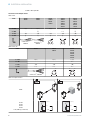 8
8
-
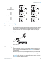 9
9
-
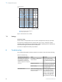 10
10
-
 11
11
-
 12
12
-
 13
13
-
 14
14
-
 15
15
-
 16
16
-
 17
17
-
 18
18
-
 19
19
-
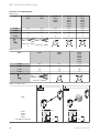 20
20
-
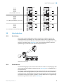 21
21
-
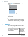 22
22
-
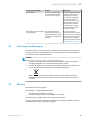 23
23
-
 24
24
-
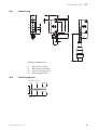 25
25
-
 26
26
-
 27
27
-
 28
28
-
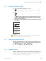 29
29
-
 30
30
-
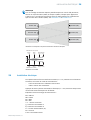 31
31
-
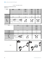 32
32
-
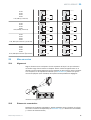 33
33
-
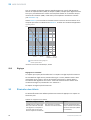 34
34
-
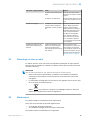 35
35
-
 36
36
-
 37
37
-
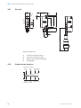 38
38
-
 39
39
-
 40
40
-
 41
41
-
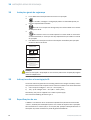 42
42
-
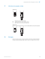 43
43
-
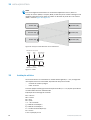 44
44
-
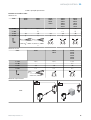 45
45
-
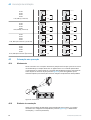 46
46
-
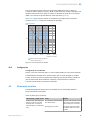 47
47
-
 48
48
-
 49
49
-
 50
50
-
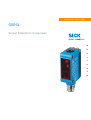 51
51
-
 52
52
-
 53
53
-
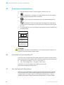 54
54
-
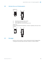 55
55
-
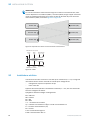 56
56
-
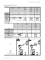 57
57
-
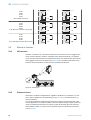 58
58
-
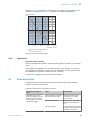 59
59
-
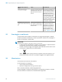 60
60
-
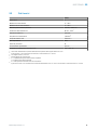 61
61
-
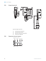 62
62
-
 63
63
-
 64
64
-
 65
65
-
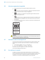 66
66
-
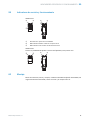 67
67
-
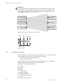 68
68
-
 69
69
-
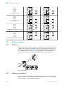 70
70
-
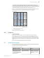 71
71
-
 72
72
-
 73
73
-
 74
74
-
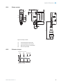 75
75
-
 76
76
-
 77
77
-
 78
78
-
 79
79
-
 80
80
-
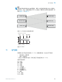 81
81
-
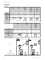 82
82
-
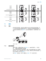 83
83
-
 84
84
-
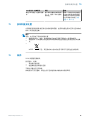 85
85
-
 86
86
-
 87
87
-
 88
88
-
 89
89
-
 90
90
-
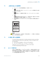 91
91
-
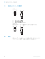 92
92
-
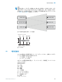 93
93
-
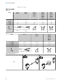 94
94
-
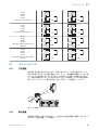 95
95
-
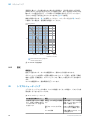 96
96
-
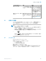 97
97
-
 98
98
-
 99
99
-
 100
100
-
 101
101
-
 102
102
-
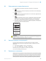 103
103
-
 104
104
-
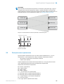 105
105
-
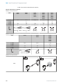 106
106
-
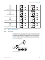 107
107
-
 108
108
-
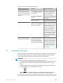 109
109
-
 110
110
-
 111
111
-
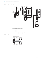 112
112
-
 113
113


en otros idiomas
- français: SICK GSE6L Mode d'emploi
- italiano: SICK GSE6L Istruzioni per l'uso
- English: SICK GSE6L Operating instructions
- Deutsch: SICK GSE6L Bedienungsanleitung
- русский: SICK GSE6L Инструкция по эксплуатации
- português: SICK GSE6L Instruções de operação
- 日本語: SICK GSE6L 取扱説明書
Artículos relacionados
-
SICK GSE6L Instrucciones de operación
-
-
SICK GL6L Instrucciones de operación
-
-
-
-
-
-
-