
F-15-755
Jun, 2005
Spanish
Instalación, funcionamiento y mantenimiento del
Fuente de alimentación de plasma
ESP 600C

El equipo descrito en este manual es
potencialmente peligroso. Tenga cuidado cuando
instale, ponga en funcionamiento y realice labores
de mantenimiento en este equipo.
El comprador es el único responsable del
funcionamiento y el uso seguro de todos los
productos adquiridos, incluido el
cumplimiento de la OSHA y otra normativa
gubernamental vigente. ESAB Cutting
Systems no se hace responsable de cualquier
lesión o daño personal ocasionado como
consecuencia del uso de cualquier producto
fabricado o vendido por ESAB. Lea las
cláusulas y condiciones de venta de ESAB
para una descripción más concreta de las
responsabilidades y limitaciones legales de
ESAB.
La más alta prioridad de ESAB Cutting
Systems es la satisfacción total del cliente.
Estamos constantemente a la búsqueda de
nuevos modos de mejorar nuestros productos,
servicios y documentación. El resultado es
que llevamos a cabo mejoras y/o realizamos
cambios cuando es necesario. ESAB se
esfuerza todo lo posible en garantizar que
nuestra documentación esté actualizada. No
podemos garantizar que cada una de las
partes de nuestra documentación refleje las
últimas mejoras de diseño. Por lo tanto, la
información contenida en este documento está
sujeta a cambios sin previo aviso.
Este manual es el número de pieza ESAB F15778
Este manual está escrito para comodidad y uso del
comprador de la máquina de corte. No representa
un contrato o cualquier otra obligación por parte de
ESAB Cutting Systems.
© ESAB Cutting Systems, 2002
Impreso en EE.UU.

Fuente de alimentación de plasma ESP-600C Índice
i
Página
Sección 1 Seguridad
1.1 Introducción.......................................................................................................... 1
1.2 Notaciones y símbolos sobre seguridad................................................................. 1
1.3 Información general sobre seguridad ..................................................................... 2
1.4 Precauciones durante la instalación....................................................................... 3
1.5 Conexión eléctrica a masa..................................................................................... 4
1.6 Manejo de una máquina de corte por plasma ........................................................ 4-7
1.7 Precauciones durante el funcionamiento................................................................ 8
1.8 Referencias de seguridad...................................................................................... 9
Sección 2 Descripción
2.1 General................................................................................................................. 1
2.2 Especificaciones generales.................................................................................... 1
2.3 Dimensiones y peso.............................................................................................. 2
Sección 3 Instalación
3.1 General................................................................................................................. 1
3.2 Desembalaje......................................................................................................... 1
3.3 Emplazamiento ..................................................................................................... 2
3.4 Conexiones de potencia de entrada ...................................................................... 2-5
3.4.1 Energía eléctrica primaria............................................................................. 3
3.4.2 Conductores de entrada.............................................................................. 4
3.4.3 Procedimiento de conexión de entrada........................................................ 4-5
3.5 Conexiones de salida ............................................................................................ 5-6
3.5.1 Cables de salida.......................................................................................... 5
3.5.2 Procedimiento de conexión de salida........................................................... 5
3.6 Instalación en paralelo........................................................................................... 6-7
3.7 Diagrama del sistema de bloqueo de interconexión del sistema con Smart Flow II.... 8
3.8 Diagrama del sistema de bloqueo de interconexión del sistema sin Smart Flow II.... 9
Sección 4 Funcionamiento
4.1 Introducción.......................................................................................................... 1
4.2 Panel de control.................................................................................................... 1-3
4.3 Secuencia de funcionamiento................................................................................ 4
4.4 Ajustes de iniciación de arco ................................................................................. 4-7
4.4.1 Activar/Desactivar el temporizador de inicio del arco ..................................... 6
4.4.2 Ajuste del temporizador de inicio de arco...................................................... 6
4.4.3 Controles de inicio del arco .......................................................................... 7
4.4.4 Corriente de inicio y temporizador de pendiente ascendente ......................... 7
4.5 Curva V-I ............................................................................................................... 8

Fuente de alimentación de plasma ESP-600C Índice
ii
Sección 5 Mantenimiento
5.1 General ................................................................................................................. 1
5.2 Limpieza................................................................................................................ 1
5.3 Lubricación del ventilador ...................................................................................... 2
Section 6 Troubleshooting (Solución de problemas)
6.1 General ................................................................................................................ 1
6.2 Fault Indicators (Indicadores de fallo)...................................................................... 1-3
6.3 Fault Isolation (Diagnostics) (Aislamiento de fallo -- diagnóstico) ............................. 4-10
6.3.1 Fans (Aislamiento de fallo -- diagnóstico)....................................................... 4
6.3.2 Power not on or Low Voltage (Sin alimentación o Voltaje bajo) ............................... 4
6.3.3 Fault Light Illumination (Iluminación de luz de fallo) ................................................... 5-8
6.3.4 Torch will not Fire (El soplete no se enciende)........................................................... 9
6.3.5 Fuses 1 and 2 Blown (Los fusibles 1 y 2 fundidos) ................................................... 10
6.3.6 Intermittent, interrupted or Partial Operation (Funcionamiento intermitente,
interrumpido o parcial)...................................................................................................................
10-12
6.4 Testing and Replacing Components (Comprobación y sustitución de componentes) ..... 13
6.4.1 Power Rectifiers (Rectificadores de alimentación) ..................................................... 14
Negative Plate (Placa negativa).................................................................................. 14
Positive Plate (Placa positiva)...................................................................................... 15
Electrode Plate (Placa de electrodo) ................................................................. 15
6.4.2 Freewheeling Diodes and IGBTs (Diodos de circulación libre e IGBTs) ................... 16-18
6.4.3 Power Shunt Installation (Instalación del derivador de alimentación) ....................... 18
6.4.4 Procedure for Verifying Calibration of Digital Meters (Procedimiento para la
comprobación de la calibración de los medidores digitales) ..........................................................
19
6.5 ESP-400C Schematic Diagrams (Diagramas esquemáticos de la unidad ESP-400C) ....... 20-27
6.6 Wiring Diagrams (Diagramas de cableado)......................................................................... 28-51
6.7 PC Controller Board (PCB1 - P/N 38032) Schematics (Esquema de la placa de
control PCB).................................................................................................................
52-56
6.8 PCB Digital Meter Board (PCB4 – P/N 38139) Schematics (Esquema de la placa de
medición digital PCB) ....................................................................................................................
57-59
6.9 IGBT Driver Board (PCB2,3 – P/N 38030) Schematics (Esquema de la placa de
transmisión IGBT)..........................................................................................................................
60-62

Fuente de alimentación de plasma ESP-600C Índice
iii
Section 7 Replacement Parts (Piezas de repuesto)
7.1 General................................................................................................................. 1
7.2 Ordering (Pedido)................................................................................................................ 1
7.3 Outside View - Front and Back (Vista exterior - frontal y posterior)................................... 2-3
7.4 Front View With PCBs Exposed (Vista frontal con los PCBs expuestos)............................ 4-5
7.5 Right Side View (Vista lateral derecho) ................................................................................ 6-7
7.6 Left Side View (Vista lateral izquierdo) ................................................................................ 8-9
7.7 Top View (Vista superior)..................................................................................................... 10-11
7.8 Back Inside View (Vista interior desde la parte posterior) ................................................... 12-13
7.9 Middle Cross Section (Sección transversal media) ............................................................ 14-15
7.10 Front Cross Section – Behind Front Panel (Sección transversal frontal - tras el panel
frontal)...........................................................................................................................................
16-17
Información cliente/técnica Contraportada del manual

Fuente de alimentación de plasma ESP-600C Índice
iv
Esta página se ha dejado en blanco intencionadamente.

SECCIÓN 1 SEGURIDAD
Fuente de alimentación de plasma ESP 600C 1-1
1.1 Introducción
El proceso de cortar metales mediante un equipo
de plasma proporciona a la industria una
herramienta valiosa y de múltiples usos. Las
máquinas de corte ESAB están diseñadas para
facilitar tanto seguridad como eficacia en el
funcionamiento. No obstante, como ocurre con
cualquier maquinaría, son necesarios una atención
razonable a los procedimientos de funcionamiento,
las precauciones y un uso seguro para lograr una
utilidad óptima. Sin importar que un individuo esté
implicado en el funcionamiento, el mantenimiento
o simplemente como mero observador deben
cumplirse las precauciones y la práctica de un uso
seguro. El hecho de no respetar ciertas
precauciones podría tener como consecuencia
lesiones personales graves o serios daños en el
equipo. Las siguientes precauciones son
directrices generales aplicables cuando trabaje con
máquinas de corte. Encontrará precauciones más
explícitas concernientes a la máquina básica y a
sus accesorios en los manuales de instrucciones.
Para una información más exhaustiva acerca de la
seguridad en el campo de equipos de corte y
soldadura, obtenga y lea las publicaciones que
figuran en la lista de Referencias recomendadas.

SECCIÓN 1 SEGURIDAD
Fuente de alimentación de plasma ESP 600C 1-2
1.2 Indicaciones de seguridad y símbolos
Las siguientes palabras y símbolos se utilizan a lo
largo de este manual. Indican diferentes niveles de
compromiso con la seguridad.
!
ALERTA o ATENCIÓN. Su seguridad corre
riesgo o existe un funcionamiento incorrecto
potencial del equipo. Se utiliza con otros
símbolos de información.
PELIGRO
!
Se utiliza para llamar la atención sobre
peligros inmediatos que, de no evitarse,
causará lesiones personales graves o incluso
la muerte.
ADVERTENCIA
!
Se utiliza para llamar la atención sobre
peligros potenciales que podrían ocasionar
lesiones personales o incluso la muerte.
PRECAUCION
!
Se utiliza para llamar la atención sobre
peligros que podrían causar lesiones
personales o daños menores en el equipo.
PRECAUCION
Se utiliza para llamar la atención sobre
peligros que pueden afectar al equipo.
AVISO
Se utiliza para llamar la atención acerca de
información importante sobre la instalación,
el funcionamiento o el mantenimiento que no
está directamente relacionada con riesgos.

SECCIÓN 1 SEGURIDAD
Fuente de alimentación de plasma ESP 600C 1-3
1.3 Información general acerca de la seguridad
ADVERTENCIA
!
La maquinaría se enciende a menudo
automáticamente.
Este equipo se mueve en diferentes direcciones y
a diferentes velocidades.
· El desplazamiento de maquinaría podría
provocar aplastamientos.
· Sólo personal cualificado deberá llevar a
cabo el funcionamiento y mantenimiento
de este generador.
· Mantenga a todo el personal, material, y
equipo que no estén implicados en el
proceso de producción lejos de todo el
área del sistema.
· Rodee con vallas toda la celda de trabajo
para evitar que el personal pase por el
área o se encuentre en el espacio de
trabajo del equipo.
· Coloque los símbolos de ADVERTENCIA
adecuados a la entrada de cada celda de
trabajo.
· Siga el procedimiento de bloqueo antes
de proceder a la reparación del equipo.
ADVERTENCIA
!
No seguir las instrucciones podría
ocasionar lesiones graves o la muerte.
Lea y comprenda este manual del operario antes
de utilizar la máquina.
· Lea el procedimiento completo antes del
funcionamiento y mantenimiento del
sistema.
· Debe prestar especial atención a las
advertencias de peligro que facilitan
información esencial relacionada con la
seguridad del personal y/o posibles
daños al equipo.
· Aquellos que tengan acceso o
responsabilidad sobre el sistema deben
cumplir estrictamente todas las
precauciones de seguridad relativas al
equipo eléctrico y su uso.
· Lea la documentación acerca de la
seguridad disponible en su empresa.

SECCIÓN 1 SEGURIDAD
Fuente de alimentación de plasma ESP 600C 1-4
ADVERTENCIA
!
No seguir las instrucciones en las
etiquetas de advertencia podría causar la
muerte o lesiones graves.
Lea y entienda todas las etiquetas de
advertencia de la máquina.
Consulte el manual del operario para obtener
más información acerca de la seguridad.
1.4 Precauciones en la instalación
ADVERTENCIA
!
El equipo instalado incorrectamente puede
causar lesiones o incluso la muerte.
Siga estas indicaciones cuando instale la máquina:
· Póngase en contacto con su
representante de ESAB antes de proceder
a la instalación. El podría aconsejarle
seguir ciertas precauciones en relación
con la instalación de tubos conductores y
el levantamiento de la máquina, etc. para
garantizar la máxima seguridad.
· No intente nunca realizar modificaciones
en la máquina o agregar complementos al
equipo sin consultar previamente con un
representante de ESAB.
· Cumpla los requisitos de distancias de
seguridad para garantizar un
funcionamiento correcto y la seguridad del
personal.
· Debe ser siempre personal cualificado el
que realice la instalación, la localización y
reparación de averías y el mantenimiento
de este equipo.
· Proporcione un desconector de pared con
fusibles del tamaño adecuado cerca del
suministro eléctrico.

SECCIÓN 1 SEGURIDAD
Fuente de alimentación de plasma ESP 600C 1-5
1.5 Conexión eléctrica a tierra
La conexión eléctrica es imprescindible para un
funcionamiento correcto de la máquina así como
para la SEGURIDAD. Consulte esta sección del
Manual de instalación para obtener instrucciones
detalladas acerca de la conexión a tierra.
PELIGRO
!
Peligro de descarga.
Una conexión a tierra incorrecta podría
ocasionar lesiones o incluso la muerte.
La máquina debe estar correctamente
conectada a tierra antes de la puesta en
funcionamiento.
1.6 Funcionamiento de una máquina de corte por plasma
ADVERTENCIA
!
Peligro por materia despedida y
ruido.
· Las salpicaduras ardiendo podrían
quemar y lesionar sus ojos. Lleve gafas
protectoras para proteger sus ojos de
quemaduras y de salpicaduras durante el
funcionamiento.
· Las astillas podrían estar ardiendo y caer
lejos. Aquellos que se encuentren en los
alrededores también deberán llevar gafas
protectoras.
· El ruido del arco de plasma podría dañar
los oídos. Lleve la protección adecuada
para sus oídos cuando corte sobre agua.
ADVERTENCIA
!
Peligro de quemaduras.
El metal caliente puede producir quemaduras.
· No toque la plancha o las piezas de metal
inmediatamente después de cortar.
Espere un tiempo hasta que el metal se
enfríe o póngalo bajo el agua.
· No toque el soplete de plasma
inmediatamente después de cortar.
Espere un tiempo hasta que se enfríe.

SECCIÓN 1 SEGURIDAD
Fuente de alimentación de plasma ESP 600C 1-6
ADVERTENCIA
!
Voltaje peligroso. Las descargas
eléctricas pueden causar la muerte.
· NO toque el soplete de plasma, la mesa
de corte o las conexiones de cables durante
el proceso de corte por plasma.
· Cierre siempre los suministros eléctricos
de plasma antes de tocar o reparar el soplete
de plasma.
· Cierre siempre los suministros eléctricos
de plasma antes de tocar o reparar cualquier
componente del sistema.
· No toque piezas eléctricas cargadas.
· Mantenga todas los paneles y cubiertas
en su lugar cuando la máquina esté
conectada a una fuente de alimentación.
· Lleve guantes, calzado y ropa de
seguridad para aislarse de la pieza de
trabajo y de la toma de tierra.
· Mantenga secos los guantes, el calzado,
la ropa, el área de trabajo y el equipo.
· Reemplace los cables gastados o
dañados.

SECCIÓN 1 SEGURIDAD
Fuente de alimentación de plasma ESP 600C 1-7
ADVERTENCIA
!
Peligro de gases.
Los vapores y gases generados por el
proceso de corte por plasma podrían ser
peligrosos para su salud.
· NO inhale el vapor o los gases.
· No utilice el soplete de plasma si el
sistema de eliminación de humos y gases no
funciona correctamente.
· Utilice sistemas de ventilación adicionales
para eliminar los humos en caso necesario.
· Utilice una mascarilla de respiración si la
ventilación no es adecuada.
· Proporcione ventilación mecánica positiva
cuando corte acero inoxidable, cobre, cinc,
berilio o cadmio. No inhale los vapores.
· No trabaje cerca de operaciones de
desengrasado y pulverización. El calor o los
rayos del arco pueden interactuar con el
hidrocarburo clorado y formar fosgeno, un
gas altamente tóxico, y otros gases irritantes.

SECCIÓN 1 SEGURIDAD
Fuente de alimentación de plasma ESP 600C 1-8
ADVERTENCIA
!
Peligro de radiación.
Los rayos del arco pueden causar daños en los
ojos y quemaduras en la piel.
· Lleve la protección correcta para cuerpo y
ojos.
· Lleve gafas de seguridad oscuras con
protección lateral. Consulte el siguiente
diagrama para el tintado de cristales
recomendado cuando corte con plasma:
Corriente del arco Filtro de la lente
Hasta 100 Amps Sombra No. 8
100-200 Amps Sombra No. 10
200-400 Amps Sombra No. 12
Más de 400 Amps Sombra No. 14
· Reemplace las gafas/lentes cuando los
cristales tengan marcas o estén rotos
· Avise a otras personas en el área para
que no miren directamente al arco a no ser
que lleven unas gafas de seguridad
adecuadas.
· Prepare el área de corte para reducir el
reflejo y la transmisión de luz ultravioleta.
§ Utilice una pintura especial en las
paredes que absorba la luz UV.
§ Instale pantallas o cortinas
protectoras para reducir la transmisión
ultravioleta.

SECCIÓN 1 SEGURIDAD
Fuente de alimentación de plasma ESP 600C 1-9
ADVERTENCIA
!
Peligro de quemaduras.
El calor, las salpicaduras y las chispas pueden
provocar fuego y quemaduras.
· No corte cerca de material inflamable.
· No lleve consigo ningún material inflamable
(p.ej. encendedor de butano).
· El arco piloto puede ocasionar quemaduras.
Mantenga la boquilla del soplete lejos de sí
mismo y de otros cuando active el proceso de
plasma.
· Lleve la protección correcta para cuerpo y
ojos.
· Lleve guantes, calzado de seguridad y gorra.
· Lleve ropa resistente al fuego que le cubra
todas las áreas expuestas.
· Lleve pantalones sin dobladillo para evitar la
entrada de chispas y residuos.
· Tenga a su alcance un equipo de extinción
de incendios.
ADVERTENCIA
!
Peligro de explosión.
· Ciertas aleaciones de aluminio-litio (Al-Li)
fundido pueden causar explosiones cuando
el corte por plasma se realiza SOBRE agua.
§ Dichas aleaciones deberán ser
cortadas en seco sobre una mesa
seca.
§ NO corte en seco sobre agua.
§ Póngase en contacto con su
distribuidor de aluminio para obtener
información de seguridad adicional
acerca de los peligros asociados con
estas aleaciones.
· No corte en ambientes impregnados de
polvo o vapores explosivos.
· No lleve ningún material inflamable
consigo (p.ej. un encendedor de butano)
· No corte contenedores que hayan
contenido sustancias inflamables.

SECCIÓN 1 SEGURIDAD
Fuente de alimentación de plasma ESP 600C 1-10
1.7 Precauciones en el servicio
PELIGRO
!
Voltaje peligroso. Las descargas
eléctricas pueden causar la muerte.
· NO toque el soplete de plasma, la mesa de
corte o las conexiones de cables durante el
proceso de corte por plasma.
· Cierre siempre los suministros eléctricos
de plasma antes de tocar o reparar cualquier
componente del sistema.
· Apague siempre los suministros eléctricos
de plasma antes de retirar las cubiertas o
paneles para reparar un componente del
sistema.
· No toque piezas eléctricas cargadas de
corriente.
· Mantenga todas los paneles y cubiertas en
su lugar cuando la máquina esté conectada a
una fuente de alimentación.
· Mantenga secos los guantes, el calzado,
la ropa, el área de trabajo y el equipo.
· Examine los cables conductores a tierra y
eléctricos para comprobar si están
desgastados o agrietados. Reemplace los
cables gastados o dañados. No los utilice si
están defectuosos.
· Nunca pase por alto los bloqueos de
seguridad.
· Siga los procedimientos de bloqueo
.
PRECAUCION
Establezca y cumpla el mantenimiento preventivo.
Se puede establecer un programa combinado a
partir de los horarios recomendados.
Evite dejar equipo de pruebas o herramientas
de mano sobre la máquina. Podrían
producirse daños eléctricos o mecánicos
graves en el equipo o en la máquina.

SECCIÓN 1 SEGURIDAD
Fuente de alimentación de plasma ESP 600C 1-11
PRECAUCION
!
Deberá proceder con sumo cuidado cuando
examine el sistema de circuitos con un
osciloscopio o con un voltímetro. Los
circuitos integrados son susceptibles de
sobretensión. Apague antes de utilizar
sondas para evitar corto circuitos
accidentales de los componentes.
Antes de que se active el suministro, deben
estar todos los cuadros del circuito en tomas
de corrientes, todos los cables conectados
correctamente, todos los armarios cerrados y
bloqueados, todos los dispositivos de
protección y cubiertas reemplazados.
1.8 Referencias de seguridad -- Reglamentos, normativa, directrices
Se recomiendan las siguientes publicaciones sobre
seguridad en las operaciones de corte y
soldadura. Estas publicaciones has sido
preparadas para proteger a las personas de
lesiones o enfermedades y para proteger la
propiedad de posibles daños ocasionados por un
uso poco seguro. Aunque algunas de estas
publicaciones no están relacionadas
específicamente con este tipo de equipo de corte
industrial, se aplican los mismos principios de
seguridad.

SECCIÓN 1 SEGURIDAD
Fuente de alimentación de plasma ESP 600C 1-12
1.8.1 EEUU
· “Precautions and Safe Practices in Welding and Cutting with Oxygen-Fuel
Gas Equipment,” (Precauciones y uso seguro en la utilización del equipo
de corte y soldadura con gas y oxígeno-combustible) Form 2035. ESAB
Cutting Systems.
· “Precautions and Safe Practices for Electric Welding and Cutting,”
(Precauciones y prácticas seguras en el corte y soldadura eléctricos)
Form 52-529. ESAB Cutting Systems.
· “Safety in Welding and Cutting” (Seguridad en corte y soldadura) - ANSI Z
49.1, American Welding Society, 2501 NW 7th Street, Miami, Florida,
33125.
· “Recommended Safe Practices for Shielded Gases for Welding and
Plasma Arc Cutting” (Prácticas seguras recomendadas para la protección
de gases durante la soldadura y el corte con arco de plasma) - AWS
C5.10-94, American Welding Society.
· “Recommended Practices for Plasma Arc Welding” (Prácticas
recomendadas para la soldadura con arco de plasma)- AWS C5.1,
American Welding Society.
· “Recommended Practices for Arc Cutting” (Prácticas recomendadas para
el corte con arco)- AWS C5.2, American Welding Society.
· “Safe Practices” (Prácticas seguras) - AWS SP, American Welding
Society.
· “Standard for Fire Protection in Use of Cutting and Welding Procedures”
(Normas para la protección en caso de fuego en la utilización de
procedimientos de corte y soldadura) - NFPA 51B, National Fire
Protection Association (Asociación Nacional de Protección contra el
fuego), 60 Batterymarch Street, Boston, Massachusetts, 02110.
· “Standard for Installation and Operation of Oxygen - Fuel Gas Systems for
Welding and Cutting” (Normas para la instalación y funcionamiento de
sistemas de gas combustible de oxígeno en la soldadura y el corte)-
NFPA 51, National Fire Protection Association.
· “Safety Precautions for Oxygen, Nitrogen, Argon, Helium, Carbon Dioxide,
Hydrogen, and Acetylene” (Precauciones de seguridad para oxígeno,
nitrógeno, argón, helio, dióxido de carbono, hidrógeno y acetileno) Form
3499. ESAB Cutting Systems. Disponible a través de su representante
de ESAB o su distribuidor local.
· "Design and Installation of Oxygen Piping Systems" (Diseño e instalación
de sistemas conductores de oxígeno) Form 5110. ESAB Cutting
Systems.
· “Precautions for Safe Handling of Compressed Gases in Cylinders”
(Precauciones para el manejo seguro de gases comprimidos en los
cilindros), CGA Standard P-1, Compressed Gas Association.
También puede solicitar documentación referente a un uso seguro en las
operaciones de corte y soldadura con materiales gaseosos a Compressed
Gas Association Asociación de gases comprimidos), Inc., 500 Fifth Ave., New
York, NY 10036.

SECCIÓN 1 SEGURIDAD
Fuente de alimentación de plasma ESP 600C 1-13
1.8.2 Internacional
Prevención de accidentes
VBG 1 Estipulaciones generales
VBG 4 Equipo eléctrico y maquinaria
VBG 15 Soldadura, corte y métodos de trabajo
relacionados
VBG 48 Trabajos de limpieza con chorro de perdigones
VBG 61 Gases
VBG 62 Oxígeno
VBG 87 Máquinas de chorro de líquido
VBG 93 Rayos láser, prevención de accidentes y electro-
tecnología
VBG 121 Ruido
Normativa VDE (Asociación Alemana de
Ingenieros Eléctricos)
VDE 0100 Montaje de instalaciones eléctricas con voltaje
normal de hasta 1000 voltios
VDE0113 Equipo eléctrico de maquinas industriales
VDE 0837 Seguridad frente a la radiación de productos
láser; guía del usuario (DIN EN 60825)
VDE 0837-
50
Especificación para dispositivos de protección
frente al láser
Normas técnicas TRAC para los depósitos de acetileno y carburo
TRAC-204 Líneas de acetileno
TRAC-206 Sistemas de batería de cilindros de acetileno
TRAC-207 Dispositivos de seguridad
Normas técnicas TRG para gases de presión
TRG 100 Normativa general para gases de presión
TRG 101 Gases a presión
TRG 102 Mezclas de gas técnicas
TRG 104 Gases a presión; uso alternativo de los
depósitos de gases comprimidos

SECCIÓN 1 SEGURIDAD
Fuente de alimentación de plasma ESP 600C 1-14
Normas DIN
DIN 2310
Parte 1
Corte térmico; terminología y nomenclatura
DIN 2310
Parte 2
Corte térmico; determinación de la calidad de las
caras de corte
DIN 2310
Parte 4
Corte térmico; corte con arco de plasma; principios
del proceso, calidad, tolerancia dimensional
DIN 2310
Parte 5
Corte térmico; corte por rayo láser de materiales
metálicos; principios del proceso
DIN 4844
Parte 1
Etiquetas de seguridad (DIN EN 7287)
Normas basadas en DIN EN ISO
DIN EN
292/1 y 2
Seguridad de la maquinaria
DIN EN 559 Tubos flexibles para soldar, cortar, y procesos
similares
DIN EN 560 Conexiones de tubos y tubos flexibles del equipo
de soldadura, corte y procesos similares.
DIN EN 561 Conexión de tubos flexibles del equipo de
soldadura con gas
DIN EN 626-
1
Seguridad de las máquinas, reducción de riesgos
para la salud
DIN EN 848-
1
Fresadoras con un solo eje vertical
DIN EN 1829 Máquinas de chorro de agua a alta presión
DIN EN 9013 Corte térmico, corte con oxígeno, principios del
proceso, tolerancia dimensional
DIN EN
12584
Imperfecciones en cortes con llama de
oxi/combustible, con rayo láser y plasma
DIN EN
12626
Máquinas de procesamiento de láser
DIN EN
28206
Prueba de aprobación de máquinas de corte con
oxígeno
DIN EN
31252
Equipo láser
DIN EN
31553
Equipo láser y relacionado con el láser
DIN EN
60204-1
Equipo eléctrico de las máquinas
DIN EN
60825
Seguridad de radiación de productos láser
DIN EN 999 Disposición de los dispositivos de protección
Normativa VDI
VDI 2906 Calidad de las caras de corte de piezas metálicas;
corte con chorro de agua abrasivo y corte con arco
de plasma
VDI 2084 Temperatura de la habitación; Sistemas técnicos
para talleres de soldadura

SECCIÓN 2 Descripción
Fuente de alimentación de plasma ESP 600C 2-1
2.1 Introducción
La fuente de alimentación ESP está diseñada para
aplicaciones de corte mecanizado de alta velocidad
mediante plasma. Se puede utilizar en combinación
con otros productos ESAB, como los sopletes PT-
15 y PT-600, junto con el Smart Flow II, un sistema
computerizado de regulación y conmutación de
gas.
· De 50 a 600 Amperios de variación de corriente
de corte
· Enfriamiento por chorro de aire a presión
· Alimentación CC de estado sólido
· Protección del voltaje de entrada
· Control local o remoto del panel frontal
· Protección de conmutador térmico para
transformador principal y componentes
semiconductores
· Capacidad de transporte de la unidad mediante
aros superiores de levantamiento o espacio
inferior para el uso de horquilla elevadora
Posibilidad de utilización de una fuente de
alimentación paralela secundaria para ampliar la
capacidad de salida de corriente.
2.2 Especificaciones generales
ESP-600C 400V,
50Hz
CE
ESP-600C 460V,
60Hz
ESP-600C
575V, 60Hz
Número de pieza 35879 35878 35880
Voltaje
200 V cc
Variación de corriente CC
De 50A a 600A
Potencia
120 KW
SALIDA(100
% ciclo de
trabajo)
Voltaje de Circuito Abierto
(VCA)
427 V cc
Voltaje (Trifásico)
400 V 460 V 575 V
Corriente (Trifásica)
206 A RMS 179 A RMS 143 A RMS
Frecuencia
50/60 HZ 60 Hz 60 Hz
KVA
142,7 KVA 142,6 KVA 142,4 KVA
Potencia
129,9 KW 129,8 KW 129,6 KW
ENTRADA
Factor de potencia
91,0 %
Fusible de entrada Nec.
250A 250A 200A

SECCIÓN 2 Descripción
Fuente de alimentación de plasma ESP 600C 2-2
2.3 Dimensiones y peso
PESO = 925,3 kg
102,2 cm
114,3 cm
94,6 cm

SECCIÓN 3 Instalación
Fuente de alimentación de plasma ESP -600C 3-1
600C
3.1 General
ADVERTENCIA
!
El incumplimiento de estas
instrucciones puede provocar la
muerte, lesiones o daños en la
propiedad.
Siga estas instrucciones para evitar
lesiones o daños en la propiedad.
Debe cumplir las normas locales, estatales
y nacionales sobre electricidad y
seguridad.
3.2 Desembalaje
PRECAUCION
Si utiliza una sola argolla de izada
dañará la chapa metálica y el
bastidor
Utilice ambas argollas de izada para el
transporte de la unidad mediante
elevamiento.
La unidad pesa aproximadamente 907 kg.
Utilice correas o cables adecuados en
buenas condiciones.
· Tras recibir el equipo, compruebe que no ha
sufrido daños durante el transporte.
· Extraiga todos los componentes del
receptáculo de transporte y compruebe que no
queden piezas sueltas en el receptáculo.
· Compruebe que no haya nada en las rejillas que
pueda obstruir el paso del aire.

SECCIÓN 3 Instalación
Fuente de alimentación de plasma ESP -600C 3-2
3.3 Emplazamiento
Atención: Utilice ambas argollas de izada para el
transporte de la unidad mediante levantamiento.
· Deberá dejarse un espacio mínimo de 0,6 m en
la parte frontal y posterior para facilitar el paso
de la corriente de aire de refrigeración.
· Tenga en cuenta que ha de dejar el espacio
necesario para retirar el panel superior y los
paneles laterales para llevar a cabo las labores
de mantenimiento, limpieza e inspección.
· Coloque la unidad ESP-600C relativamente
cerca de una toma de corriente provista de
fusible.
· Mantenga despejada la superficie situada
debajo de la fuente de alimentación para facilitar
el paso de la corriente de aire de refrigeración.
· El entorno deberá estar relativamente libre de
polvo, gases y calor excesivo. Estos factores
afectarán la capacidad de refrigeración.
PRECAUCION
La existencia de elementos
conductores en forma de polvo y
suciedad dentro de la fuente de
alimentación puede provocar una
descarga por arco.
El equipamiento puede resultar dañado. Se
puede producir un cortocircuito eléctrico si se
permite la acumulación de polvo en el interior
de la fuente de alimentación. Consulte la
sección de mantenimiento.
3.4 Conexión de potencia de entrada
ADVERTENCIA
!
¡La descarga eléctrica puede
resultar mortal!
Tome todas las precauciones posibles para
evitar una descarga eléctrica.
Antes de realizar cualquier conexión en el
interior de la máquina, abra el dispositivo de
desconexión de línea y apague la unidad.
Fuente de
alimentación

SECCIÓN 3 Instalación
Fuente de alimentación de plasma ESP -600C 3-3
3.4.1 Energía eléctrica primaria
La ESP-600C es una unidad trifásica. La potencia
de entrada debe proceder de un dispositivo de
desconexión de línea (exterior) provisto de fusibles o
cortacircuitos en regla, según las normativas locales
o estatales.
Capacidades recomendadas para conductores de
entrada y fusibles de línea:
Carga especificada Conductor* de
entrada y de
masa
Voltios Amperios
AWG/Cu
mm
2
Capacidad
del fusible
de acción
retardada
(amperios)
400
460
575
138
120
96
4/0
3/0
1/0
120
95
55
200
150
125
*Capacidades según el NEC (National Electrical Code) para un
conductor de cobre normal a una temperatura de 90°C y una
temperatura ambiente de 40°C. No más de tres conductores
por canal de conducción o cable. Se debe cumplir la
normativa local en caso de que ésta especifique unas
capacidades diferentes a las expuestas anteriormente.
(Voltaje de arco) x (Corriente de arco) x 0,688
Corriente de entrada =
(Voltaje de línea)
AVISO
Puede que se necesite una línea de
alimentación desactivada.
La unidad ESP-600C está equipada con un
sistema de compensación de voltaje de línea,
aunque para evitar una merma en el rendimiento
a causa de un circuito sobrecargado, es posible
que se requiera una línea de alimentación
desactivada.

SECCIÓN 3 Instalación
Fuente de alimentación de plasma ESP -600C 3-4
3.4.2 Conductores de entrada
· Suministrados por el cliente
· Puede tratarse de conductores de cobre
recubiertos de una gruesa capa de goma (tres
de alimentación y uno de masa) o simplemente
de canalizaciones sólidas o flexibles.
· Capacidades de acuerdo con la tabla.
AVISO
Los conductores de entrada deben acabar
en terminales de anillo.
Los conductores de entrada deben disponer de
terminales de anillo diseñados para piezas de
12,7 mm, antes de unirse a la unidad ESP-600C.
3.4.3 Procedimiento de conexión de entrada
1. Retire el panel lateral izquierdo de la unidad
ESP-600C
2. Introduzca los cables a través del orificio de
acceso del panel posterior.
3. Asegure los cables con un protector contra
tirones o un manguito de unión (no incluido) al
orificio de acceso.
4. Conecte el cable de masa al borne de la base
del armazón.
5. Conecte los terminales de anillo del cable de
alimentación a los terminales principales con las
clavijas, arandelas y tuercas suministradas.
6. Conecte los conductores de entrada al
dispositivo de desconexión de línea (exterior).
Masa del chasis
Cable entrada alim.
Abertura acceso
(panel trasero)
Terminales
primarios

SECCIÓN 3 Instalación
Fuente de alimentación de plasma ESP -600C 3-5
ADVERTENCIA
!
¡La descarga eléctrica puede
resultar mortal!
Los terminales de anillo deben dejar un
espacio entre el panel lateral y el
transformador principal. Esta holgura debe
ser suficiente para evitar la formación de un
arco eléctrico.
Asegúrese de que los cables no interfieren el
giro normal del ventilador de refrigeración.
ADVERTENCIA
!
Una conexión a masa inadecuada
puede dar como resultado la muerte
o lesiones.
El armazón debe quedar conectado a una
masa eléctrica autorizada.
Asegúrese de que el cable de masa NO está
conectado a ningún terminal primario.

SECCIÓN 3 Instalación
Fuente de alimentación de plasma ESP -600C 3-6
3.5 Conexiones de salida
ADVERTENCIA
!
¡La descarga eléctrica puede
resultar mortal! ¡Voltaje y corriente
peligrosos!
Siempre que se trabaje en las cercanías de
una fuente de alimentación de plasma con las
cubiertas retiradas.
· Desconecte la fuente de alimentación en
el dispositivo de desconexión de línea
(exterior).
· Una persona cualificada deberá
comprobar las barras colectoras (positiva
y negativa) con un voltímetro.

SECCIÓN 3 Instalación
Fuente de alimentación de plasma ESP -600C 3-7
3.5.1 Cables de salida (suministrados por el cliente)
Escoja cables de salida para corte mediante plasma
(suministrados por el cliente) sobre la base de un
cable de cobre aislado de 4/0 AWG, 600 voltios por
cada 400 amperios de corriente de salida.
!
Atención: No utilice cable de soldeo
aislado de 100 voltios.
3.5.2 Procedimiento de conexión de salida
1. Retire el panel de acceso situado en la parte
inferior delantera de la fuente de alimentación.
2. Pase los cables de salida a través de los
orificios de la parte inferior en el panel frontal o
en la parte inferior de la fuente de alimentación,
inmediatamente detrás del panel frontal.
3. Conecte los cables en los terminales
designados montados en el interior de la fuente
de alimentación utilizando los conectores de
cable de presión incluidos en la unidad.
4. Vuelva a colocar el panel retirado en el primer
paso del procedimiento.
Panel de
acceso

SECCIÓN 3 Instalación
Fuente de alimentación de plasma ESP -600C 3-8
3.6 Instalación en paralelo
Se pueden conectar dos fuentes de alimentación
400A para ampliar la capacidad de salida de
corriente.
PRECAUCION
La corriente de inicio de la fuente de
alimentación paralela supera las
cantidades recomendadas cuando se corta
por debajo de 100A.
Utilice solamente una fuente de alimentación
para obtener una corriente inferior a 100A.
Recomendamos la desconexión del cable
negativo de la fuente de alimentación
secundaria cuando se haya de cambiar a una
corriente inferior a 100 amperios. El extremo
de este cable debe ser protegido
convenientemente para evitar descargas
eléctricas.

SECCIÓN 3 Instalación
Fuente de alimentación de plasma ESP -600C
3-9
!
Atención: La fuente de alimentación primaria
tiene puenteado el conductor del electrodo (-).
La fuente de alimentación secundaria tiene
puenteado el electrodo de trabajo (+).
1. Conecte los cables de salida negativos (-) a la
línea de alta frecuencia (generador de alta
frecuencia).
2. Conecte los cables de salida positivos (+) a la
pieza a soldar por resistencia.
3. Conecte los conductores positivo (+) y negativo
(-) entre las dos fuentes de alimentación.
4. Conectar el cable del arco piloto al terminal del
arco piloto en la fuente de poder primaria. La
conexión para el cable del arco piloto de la
fuente de poder secundaria no es utilizado. El
circuito de arco piloto no trabaja en paralelo.
5. Ajuste el interruptor ALTO/BAJO del arco piloto
en la fuente de alimentación secundaria en
"BAJO".
6. Ajuste el interruptor ALTO/BAJO del arco piloto
en la fuente de alimentación primaria en
"ALTO".
ADVERTENCIA
!
¡La descarga eléctrica puede
resultar mortal!
¡Los conductores eléctricos
desprotegidos pueden resultar
peligrosos!
No deje ningún conductor "con corriente"
desprotegido. Desconecte ambos
extremos del conductor para su seguridad.
Si utiliza una sola fuente de alimentación
en una configuración en paralelo, el
conductor del electrodo negativo debe ser
desconectado de la fuente de alimentación
secundaria y de la línea de alta frecuencia.
En caso de no hacerlo, la segunda unidad
estaría conectada a la corriente eléctrica.
(-)
(+)
(-)
(+)
3 - 4/0 600V
3 - 4/0 600V
Fuente de Poder
Secundaria
Fuente de Poder
Primaria
Trabajo Trabajo
Electrodo
Electrodo
Cables negativos a
la caja de plomería
(generador de a.f.)
Cables positivos
para la pieza
de trabajo
Quite la conexión negativa
de la fuente de poder
secundaria e lo aísle
para convertir de dos
para una fuente
de poder
Electrodo
(-)
Trabajo
(+)
(-)
(+)
3 - 4/0 600V
3 - 4/0 600V
Cables
positivos
para la pieza
de trabajo
Fuente de Poder
Primaria
Fuente de Poder
Secundaria
4/0 600V
Puentes
entre las
unidades
1 - 14 AWG 600V
Cable para la
conexión del
arco piloto a
la caja de
plomería
(generador de
a.f.)
Arco piloto
Electrodo
Trabajo
Cables
negativos a
la caja de
plomería
(generador de
a.f.)
Conexiones para instalación de 2
fuentes en paralelo.

SECCIÓN 3 Instalación
Fuente de alimentación de plasma ESP -600C 3-10
3.7 Diagrama del bloqueo de interconexión del sistema con SmartFlow II
N2
O2
Air
H-35
1
2
3
4
5
6
7
8
9
10
11
12
13
14
15
16
17
18
6
0
0
C

SECCIÓN 3 Instalación
Fuente de alimentación de plasma ESP -600C 3-11
Diagrama del bloqueo de interconexión del sistema con SmartFlow II
1 Trifásica c/masa
2 Vista frontal
3 Vista posterior
4 Remoto a CNC
5 CNC
6 E/S CNC a SmartFlow II
7 Soplete(-)
8 Arco piloto
9 Electrodo de trabajo (+)
10 SmartFlow II
11 Bomba de corte de agua (PT-15)
12 Agua de refrigeración a soplete
13 Agua de refrigeración desde soplete
14 Control de voltaje alto
15 Haz de sopletes de plasma y soplete
16 Conexión a masa
17 Control On-Off
18 Refrigerador de agua WC-7

SECCIÓN 3 Instalación
Fuente de alimentación de plasma ESP -600C 3-12
3.8 Diagrama del bloqueo de interconexión del sistema con control manual de flujo
1
2
3
4
5
6
7
8
9
10
11
12
13
14
15
16
17
18
19
20
21
22
23
24
25
26
27
28
29
30
31
32
33
34
35
36
37
38
39
40
41
42
43
44
46
47
5
45

SECCIÓN 3 Instalación
Fuente de alimentación de plasma ESP -600C 3-13
Diagrama del bloqueo de interconexión del sistema con control manual de flujo
1 Reguladores de gas 25 Solenoide de gas de incio
2 Oxigeno 26 Refrigerador y bomba
3 Nitrògeno 27 Toma de corriente
4 Bomba de agua de corte 28 Corriente de entrada
5 On-Off 29 Fuente de alimentoción
6 Corte de agua 30 Retorno de refigerante
7 Control de flujo 31 Salida de refrigerante
8 Proceso OK 32 (+) Pieza de trabajo
9 Interbloqueos 33 (-) Electrodo
10 Ref. corriente 34 Arco Piloto
11 E-parada 35 Línea de alta frecuencia
12 Control máquina de corte 36 Bloque de medición de gas
13 Ref. Altura 37 Gas de atmósfera inerte
14 Proceso Off 38 Sum. de aire
15 Soplete – PT-15XL o PT-19XLS o PT-600 39 Gas
16 Control altura 40 Arco piloto alta frec.
17 Voltaje de pieza de trabajo 41 Inyecciónde agua
18 Respuesta de voltaie 42 Refrigerante hacia – Corriente (-) hacia
19 Gas de corte 43 Refrigerante desde – Corriente (-) hacia
20 Gas de incio 44 Pieza de trabajo
21 Agua de inyección 45 Conexión a masa
22 Interbloqueos
Inscripción
23 Altrafrecuencia. On-Off 46 Conexiones eléctricas
24 Solenoide de gas de corte 47 Lineas de fluidos

SECCIÓN 3 Instalación
Fuente de alimentación de plasma ESP -600C 3-14
Esta página se ha dejado en blanco intencionadamente.

SECCIÓN 4 Funcionamiento
Fuente de alimentación de plasma ESP 600C 4-1
4.1 Introducción
La unidad ESP-600C no tiene ningún interruptor
ON/OFF. La línea de alimentación principal se
controla a través del dispositivo de desconexión de
la línea (exterior).
ADVERTENCIA
!
No utilice la unidad ESP-600C sin las
cubiertas.
Los componentes de alta tensión están al
descubierto, por lo que aumenta el riesgo
de descarga eléctrica.
Los componentes internos pueden
dañarse, ya que los ventiladores de
refrigeración pierden eficacia.
4.2 Panel de control
Línea de alimentación principal
El indicador se ilumina cuando la potencia de
entrada se aplica a la fuente de alimentación.
Sobrecalentamiento
El indicador se ilumina cuando la fuente de
alimentación se ha sobrecalentado.
Contactor On
El indicador se ilumina cuando el contactor principal
se activa.

SECCIÓN 4 Funcionamiento
Fuente de alimentación de plasma ESP 600C 4-2
Fallo
El indicador se ilumina cuando aparecen anomalías
en el proceso de corte o cuando el voltaje de la
línea de entrada difiere del valor nominal requerido
en ±10%.
Fallo de reinicio de alimentación
El indicador se ilumina cuando se detecta un fallo
grave. La potencia de entrada deberá
desconectarse durante al menos 5 segundos, para
luego volver a aplicarla.
Dial de corriente (Potenciómetro)
Dial de la unidad ESP-600C. La unidad ESP-600C
ofrece una variación posible que va de 50 a 600 A.
Se utiliza tan sólo en el modo panel.
Interruptor Panel/Señal remota
Controla la ubicación del control de corriente.
· Coloque en la posición PANEL para controlar la
unidad desde el potenciómetro actual.
· Coloque en la posición REMOTE para controlar
la unidad desde una señal externa (CNC).
Conexión remota
Toma Amphenol de 19 pins para conectar la fuente
de alimentación al CNC.
Interruptor de arco piloto HIGH/LOW
Se utiliza para seleccionar la cantidad de corriente
de arco piloto deseada. Por regla general, para
intensidades de 100 amperios o inferiores, se utiliza
el valor LOW (bajo). Esto puede variar dependiendo
del gas, material y soplete utilizado. Los ajustes
High/Low (alto/bajo) se especifican en la
información de corte incluida en el manual del
soplete.

SECCIÓN 4 Funcionamiento
Fuente de alimentación de plasma ESP 600C 4-3
Medidores
Muestran el voltaje y el amperaje en el momento de
corte. El amperímetro puede activarse aunque no
sea en el momento de corte para ver una
estimación de la corriente de corte antes de que
éste comience.
Interruptor Actual/Preset
Este interruptor se mantiene de modo
predeterminado en la posición ACTUAL. Cuando
se presiona hacia abajo, el AMPERÍMETRO
muestra una estimación de la corriente real. Esto
permite al operador preseleccionar una corriente de
corte cercana a la corriente deseada utilizando el
potenciómetro de corriente.
Los ajustes finales se realizan después de que el
soplete haya comenzado a cortar para conseguir
una corriente más precisa.
ADVERTENCIA
!
¡Voltaje y corriente peligrosos!
¡La descarga eléctrica puede
resultar mortal!
Antes de iniciar el funcionamiento de la unidad,
asegúrese de que los procedimientos de
instalación y de conexión a masa se han
seguido correctamente.
No trabaje con la unidad mientras tenga
retiradas sus cubiertas.

SECCIÓN 4 Funcionamiento
Fuente de alimentación de plasma ESP 600C 4-4
Begin
Cutting
ACTUAL AMPS
PRESET AMPS
HIGH
LOW
PILOT
ARC
PANEL
REMOTE
Apply Power
4.3 Secuencia de funcionamiento
1. Conecte la unidad a la corriente eléctrica
cerrando el interruptor de línea (exterior). (La
unidad ESP-600C no tiene ningún interruptor
ON/OFF). La luz indicadora de alimentación
principal se iluminará y la luz de fallo parpadeará
y después se apagará.
2. Seleccione el ajuste Panel/Remote.
3. Ajuste el interruptor de arco piloto High/Low.
(Consulte la información sobre corte en el
manual del soplete.)
4.
Si utiliza el modo panel, compruebe la
intensidad preseleccionada con el interruptor
ACTUAL/PRESET AMPS. Ajuste el nivel de
corriente hasta que el valor deseado
aproximado aparezca en el amperímetro.
5.
Comience la operación de corte por plasma.
Esto puede incluir el ajuste manual de otras
opciones, dependiendo del volumen total de
plasma.
6.
Si se utiliza el modo panel, tras iniciar la
operación de corte, ajuste la corriente a la
cantidad deseada.
7.
Compruebe la luz indicadora de fallo. Si alguna
luz de fallo se ilumina, consulte la sección de
Solución de problemas.
Atención: La luz de fallo parpadea cuando el
contactor se activa por primera vez, lo que quiere
decir que el Bus CC se ha activado con normalidad.

SECCIÓN 4 Funcionamiento
Fuente de alimentación de plasma ESP 600C 4-5
Cut Current
1
OUT
= 50 V
REF
1
OUT
= 50 V
REF
4.4 Ajustes de iniciación de arco
El tiempo necesario para conseguir una corriente
completa puede ajustarse de modo que se adecue
a su sistema concreto. Esta opción utiliza un 50%
de la corriente de corte para su arranque, se
detiene y después, gradualmente (menos de un
segundo), consigue una corriente completa. La
unidad ESP-600C se suministra con esta opción
activada. La configuración predeterminada es la
siguiente:
Corriente de inicio mínima 40A
Corriente de inicio 50% de corriente
de corte
Tiempo necesario para
conseguir una corriente
completa
800 mseg
Tiempo de parada 50 mseg
Forma de la onda de la corriente de inicio con arco
Temporizador de inicio OFF
Approx. 2 mseg hasta corriente
completa
Corriente de salida CC
Forma de la onda de la corriente de inicio con arco
Temporizador de inicio ON
Corriente
De prada
Corriente de salida CC
Tiempo
hasta corriente completa
a 800 mseg
Estas funciones de temporización puede
desactivarse o ajustarse para adecuarse a los
requisitos individuales de cada sistema.

SECCIÓN 4 Funcionamiento
Fuente de alimentación de plasma ESP 600C 4-6
12
ON
OFF
ADVERTENCIA
!
¡La descarga eléctrica puede
resultar mortal!
Desconecte la unidad en el dispositivo de
desconexión general de línea (exterior)
antes de retirar las cubiertas o realizar
cualquier tipo de ajuste en la fuente de
alimentación.
4.4.1 Activar/Desactivar el temporizador de inicio del arco
Configuración predeterminada de fábrica
1.
Retire el panel de acceso de la esquina superior
derecha del panel frontal. Asegúrese de volver
a colocar este panel después de realizar los
ajustes.
2. Localice los interruptores SW1 y PCB1, y
púlselos para desactivarlos. Para volver a
activarlos, púlselos de nuevo hacia arriba. (Si
un interruptor está hacia arriba y el otro hacia
abajo, el tiempo de inicio de arco se considera
activado.)
4.4.2 Ajuste del temporizador de inicio de arco
Corriente de inicio mínima
Controlada mediante la selección de posiciones de
la 5 a la 8 en SW2. Cuando se presiona un
interruptor, su valor se añade al valor mínimo
establecido de fábrica (40A).
Interruptor #5 = 80A mín. corriente de inicio
Interruptor #6 = 40A mín. corriente de inicio
Interruptor #7 = 20A mín. corriente de inicio
Interruptor #8 = 10A mín. corriente de inicio
ON
OFF
12345678
SW2
Tiempo de parada
Controlada mediante la selección de posiciones de
la 1 a la 4 SW2 en PCB1. Cuando se presiona un
interruptor, su valor se añade al tiempo mínimo de
parada (10 mseg).
Interruptor #1 = 10 mseg de tiempo de parada
Interruptor #2 = 20 mseg de tiempo de parada
Interruptor #3 = 40 mseg de tiempo de parada
Interruptor #4 = 80 mseg de tiempo de parada
El ajuste predeterminado se da con el interruptor #3
activado. 40 mseg + 10 mseg (mínimo) = 50 mseg
Configuración predeterminada de fábrica
SW1

SECCIÓN 4 Funcionamiento
Fuente de alimentación de plasma ESP 600C 4-7
4.4.3 Controles de inicio del arco
Retire el dfd
4.4.4 Corriente de inicio y temporizador de pendiente ascendente
90%
80%
70%
60%
50%
40%
30%
20%
10%
0%
0 1 2 3 4 5 6 7 8 9 10 MÁX
Ajuste del potenciómetro de covviente de salida
Porcentaje (%) de corriente de salida
Corriente de inicio (%) y relación del
potenciómetro
Corriente de inicio
Ajústela con el potenciómetro situado encima y a la
izquierda del centro del PCB1. El valor
predeterminado de fábrica es 7.
Temporizador de pendiente ascendente
Interruptor de tres posiciones situado junto al
potenciómetro de corriente de inicio. Marca el
tiempo que va desde la corriente de inicio (después
de que acabe la parada) hasta alcanzar la corriente
completa. Valor de fábrica = 800 mseg
Posición izquierda = 250 mseg
Posición central = 800 mseg
Posición derecha = 1.200 mseg
SW2
SW1
Potenciómetro de
corriente de inicio
Temporizador de
corriente

SECCIÓN 4 Funcionamiento
Fuente de alimentación de plasma ESP 600C 4-8
450
400
350
300
250
200
150
100
50
100
200
300
400
500
600
700
V
REF
=0,625v
V
REF
=1,000v
V
REF
=2,000v
V
REF
=3,000v
V
REF
=4,000v
V
REF
=5,000v
V
REF
=6,000v
V
REF
=7,000v
V
REF
=7,500v
I
OUT
= (80) X (V
REF
)
4.5 Curvas V-I de la unidad ESP-600C
427 v Circuito abierto (Modelos
460 & 575 v)
410 v Circuito abierto (Modelo 400 v)
Salida de arranque
/
Circito de inicio
Voltaje salida Máx
@Línea nominal
Corriente Máxima
Corriente Mínima
Limite interno de Dorriente
Output Voltage (volts)
Corriente de Salida (Amperios)

SECCIÓN 5 Mantenimiento
Fuente de alimentación de plasma ESP 600C
5-1
5.1 General
ADVERTENCIA
!
¡La descarga eléctrica puede
resultar mortal!
Desconecte la unidad en el dispositivo de
desconexión general de línea de corriente
antes de realizar cualquier labor de
mantenimiento.
ADVERTENCIA
!
Protéjase los ojos cuando utilice
aire comprimido para limpiar.
· Utilice gafas protectoras con
protecciones laterales cuando limpie la
fuente de alimentación.
· Utilice sólo aire de baja presión.
PRECAUCION
!
Las labores de mantenimiento de
este equipo sólo deberán ser
realizadas por personal cualificado.
5.2 Limpieza
Para evitar problemas en el funcionamiento de la
unidad es necesario limpiar la fuente de
alimentación con regularidad. La frecuencia de
limpieza depende del entorno y del uso.
1. Desconecte la unidad en el dispositivo de
desconexión general.
2. Retire los paneles laterales.
3. Utilice aire comprimido seco de baja presión,
limpie el polvo de todos los conductos de aire y
demás componentes. Ponga especial atención
en los disipadores térmicos de la parte frontal
de la unidad. El polvo actúa como aislante y
reduce la disipación del calor. No olvide utilizar
gafas protectoras.

SECCIÓN 5 Mantenimiento
Fuente de alimentación de plasma ESP 600C
5-2
PRECAUCION
Las restricciones de aire pueden
causar el sobrecalentamiento de la
unidad ESP-600C.
Los conmutadores térmicos podrían
activarse, causando la interrupción del
funcionamiento de la unidad.
No utilice filtros de aire en esta unidad.
Mantenga los conductos de aire limpios de
polvo y otros obstáculos.
5.3 Lubricación
· Algunas unidades están equipadas con tubos
de lubricación en los ventiladores. Estos
ventiladores deberían lubricarse después de un
año de funcionamiento.
· El resto de unidades ESP-600C tienen motores
de ventiladores que se lubrican continuamente y
no necesitan un mantenimiento regular.
ADVERTENCIA
!
¡Peligro de descarga eléctrica!
Asegúrese de volver a colocar todas las
cubiertas retiradas durante la limpieza
antes de volver a conectar la unidad.

SECTION 6 Troubleshooting
ESP 400C and 600C Plasma Power Sources
6-1
VOLTS
AMPS
OUTPUT
ACTUAL AMPS
PRESET AMPS
LOW
HIGH
PILOT
ARC
50
MIN
100
200
300
400
500
600
MAX
0
MAIN
POWER
CURRENT
PANEL
REMOTE
OVER
TEMP
CONTACTOR
ON
FAULT
POWER
RESET
FAULT
600C
WARNING
!
6.1 General
Electric Shock Can Kill!
Do not permit untrained persons to inspect
or repair this equipment.
Electrical work must be performed by an
experienced electrician.
CAUTION
!
Stop Work Immediately If Power
Source Does Not Work Properly.
Have only trained personnel investigate
the cause.
Use only recommended replacement parts.
6.2 Fault Indicators
Fault indicators are found on the front panel
Used with the LEDs on PCB1 (located behind
the cover with the ESP label) problems can be
diagnosed.
NOTE: Momentary lighting (flashing) is normal
and does not indicated a fault.
Fault Indicator used with:
LED 3
LED 4
LED 5
LED 7
LED 8
Power Reset Fault Indicator used with:
LED 6
LED 9
LED 10
LED 11
LED 12
LED 13
Front Panel Fault Indicators
PCB1 Located
behind this panel.

SECTION 6 Troubleshooting
ESP 400C and 600C Plasma Power Sources
6-2
Fault Indicator (Front Panel)
Illuminates when there are abnormalities in the
cutting process or when the input voltage falls
±10% outside the normal value. Momentary
illumination is normal. If continuously lit, check
LEDs 3, 4, 5, 7, and 8 on PCB1 for further
diagnosis.
LED 3 – (amber) Bus Ripple Fault -
Momentarily illuminates at the beginning of each
cut. Continuously lit during single-phasing or
imbalanced line-to-line voltages of the three phase
input line.(Excessive Ripple) Power Source is shut
down.
LED 4 – (amber) High Bus Fault – Illuminates
when input line voltage is too high for proper
operation (approx. 20% above nominal line voltage
rating). Power source is shut down.
LED 5 – (amber) Low Bus Fault – Illuminates
when input line voltage is approx. 20% below
nominal line voltage rating. PS is shut down.
LED 7 – (amber) Arc Voltage Saturation Fault
– Illuminates when the cutting arc voltage is too
high and cutting current drops below preset level.
LED will extinguish after voltage decreases and
current rises.
LED 8 – (amber) Arc Voltage Cutoff Fault –
Illuminates when arc voltage increases over the
preset value. PS is shut down.

SECTION 6 Troubleshooting
ESP 400C and 600C Plasma Power Sources
6-3
Power Reset Fault Indicator (on front panel)
Illuminates when a serious fault is detected. Input
power must be disconnected for a least 5 seconds
to clear this fault. Check PCB1 Red LEDs 6, 9, 10,
11, 12, and 13 if this fault is illuminated for further
diagnosis.
LED 6 – (red) Right Overcurrent Fault –
Illuminates when the current out of the right side
chopper is too high (300 amps). This current is
measured by the right-side hall sensor. The power
source is shut down.
LED 9 – (red) Left Overcurrent Fault –
Illuminates when the current from the left side
chopper is too high (300 amps). Measured by the
left hall sensor. Power source is shut down.
LED 10 _ (red) Left IGBT Unsaturated Fault –
Illuminates when left IGBT is not fully conducting.
PS (PS) is shut down.
LED 11 – (red) Right IGBT Unsaturated Fault –
Illuminates when right IGBT is not fully conducting.
Power Source (PS) is shut down.
LED 12 – (red) Left -(neg) 12V Bias Supply
Fault – Illuminates when negative 12 V bias supply
to the left side IGBT gate drive circuit (located on
PWM-drive board PCB2) is missing. PS is shut
down.
LED 13 – (red) Right –(neg) 12V Bias Supply
Fault - Illuminates when negative 12 V bias supply
to the right side IGBT gate drive circuit (located on
PWM-drive board PCB3) is missing. PS is shut
down.

SECTION 6 Troubleshooting
ESP 400C and 600C Plasma Power Sources
6-4
6.3 Fault Isolation
Many of the most common problems are listed by
symptom.
6.3.1 Fans not working
6.3.2 Power not on
6.3.3 Fault Light Illumination
6.3.4 Torch won’t fire
6.3.5 Fusses Blown F1 and F2
6.3.6 Intermittent, Interrupted or Partial Operation
6.3.1 Fans Not Working
Problem Possible Cause Action
All Three fans do not run
This is normal when not cutting.
Fans run only when “Contactor On”
signal is received.
None
One or two fans do not run.
Broken or disconnected wire in fan
motor circuit.
Faulty fan(s)
Repair wire.
Replace fans
6.3.2 Power Not On or LOW Voltage
Problem Possible Cause Action
Power source inoperable:
Main Power lamp is off.
Missing 3-phase input voltage
Missing 1 of 3-phase input voltage
Restore all 3 phases of input voltage
to within ±10% of nominal line.
Restore all 3 phases of input voltage
to within ±10% of nominal line.
Low Open Circuit Voltage
Fuse F3 blown
Pilot arc Contactor (K4) faulty
Faulty Control PCB1
Replace F3
Replace K4
Replace Control PCB1 (P/N 38032)

SECTION 6 Troubleshooting
ESP 400C and 600C Plasma Power Sources
6-5
6.3.3 Fault Light Illumination
Problem Possible Cause Action
Fault light illuminates at the end of
cut but goes off at the start of the
next.
Normal condition caused by
terminating the arc by running the
torch off the work or the arc being
attached to a part that falls away.
Reprogram cutting process to
ensure arc is terminated only by
removing the “Contactor On” signal.
LED 3 – (amber) Bus Ripple
Imbalance of 3-phase input power
Momentary loss of one phase of
input power
Faulty control PCB1
Maintain phase voltage imbalance of
less than 5%.
Restore and maintain input power
within ±10% nominal
Replace PCB1 P/N 38032
LED 4 – (amber) High Bus
One or more phases of input voltage
exceed nominal line voltage by more
than 20%.
Faulty control PCB1
One or more shorted diode rectifiers
(D25-D28) on the “Electrode Plate”
Restore and maintain line voltage
within ±10%
Replace PCB1 P/N 38032
Replace shorted diode rectifiers
LED 5 – (amber) Low Bus
One or more phases of input voltage
are lower than nominal by more than
15%.
Blown F1 and F2 fuses
Over temp Light comes on.
Imbalanced 3-phase input power
Momentary loss of one phase of
input power
Faulty Main Contactor (K1)
FAULTY Control PCB1
Restore and maintain with in ±10%
of nominal
See F1 and F2 in Blown Fuses
Section
See over temp in Fault Light Section
Maintain phase voltage imbalance of
less than 5%
Restore and maintain within ±10% of
nominal
Replace K1
Replace PCB1 P/N 30832

SECTION 6 Troubleshooting
ESP 400C and 600C Plasma Power Sources
6-6
Problem Possible Cause Action
LED 6 – (red) Right Over Current
Note:
If operation at 250A or less is
possible, then the LEFT side is
not working.
Output current of the right side
exceeds 200A because of operating
the power source over 400A.
Cutting at over 250A with a faulty
left side (left side output = 0)
Right current transducer connector
loose or unplugged. PCB loose.
Loose or unplugged connector at
right PWM/Drive Printed circuit
board.
P2 at left of PWM/Drive PCB loose or
unplugged.
Check voltage between P7-6 and
P7-7. A voltage in either polarity of
greater than 0.01 V indicates a faulty
right current transducer (TD2).
Faulty PCB1
Faulty right PWM/Drive PCB
Turn the output current down to
400A
See faulty left or right side
Secure connections
Secure connection
Secure connection
Replace right current transducer
(TD2)
Replace PCB1 P/N 30832
Replace right PWM/Drive PCB P/N
38030
LED 6 – (red) Left Over Current
Note:
If operation at 250A or less is
possible, then the Right side is
not working.
Output current of the left side
exceeds 250A because of operating
the power source over 400.
Cutting at over 250A with a faulty
right side (right side output = 0)
Left current transducer connector
loose or unplugged. PCB loose.
Loose or unplugged connector at left
PWM/Drive Printed circuit board.
P2 at right of PWM/Drive PCB loose
or unplugged.
Check voltage between P7-2 and
P7-3. A voltage in either polarity of
greater than 0.01 V indicates a faulty
left current transducer (TD1).
Faulty PCB1
Faulty left PWM/Drive PCB
Turn the output current down to
400A
See faulty right side
Secure connections
Secure connection
Secure connection
Replace left current transducer (TD1)
Replace PCB1 P/N 38032
Replace left PWM/Drive PCB P/N
38030

SECTION 6 Troubleshooting
ESP 400C and 600C Plasma Power Sources
6-7
Problem Possible Cause Action
Very high Output current
accompanied by either a left or
right over current (LED 6)
Shorted IGBT
Current pot set too high
Faulty left PWM/Drive PCB
High remote current signal
Faulty PCB1
Replace the pair of IGBTs containing
the shorted IGBT
Lower the current setting
Replace left PWM/Drive PCB
Decrease remote current signal
Replace PCB1 P/N 38032
LED 10 - (red) Left IGBT
Unsaturated
Black wire connecting IGBT (Q4)
collector to P3 of the left PWM/Drive
PCB (PCB2) is disconnected.
Shorted Freewheeling Diode(s)
Loose or unplugged P1 connector at
the left PWM/Drive PCB
Loose or unplugged P10 connector
at PCB1
Faulty PCB1
Faulty left PWM/Drive PCB
Secure connector
Replace freewheeling diode(s)
Secure P1
Secure P10
Replace PCB1 P/N 38032
Replace PCB2 P/N 38030
LED 11 - (red) Right IGBT
Unsaturated
Black wire connecting IGBT (Q4)
collector to P3 of the right
PWM/Drive PCB (PCB3) is
disconnected.
Shorted Freewheeling Diode(s)
Loose or unplugged P1 connector at
the left PWM/Drive PCB
Loose or unplugged P10 connector
at PCB1
Faulty PCB1
Faulty right PWM/Drive PCB
Secure connector
Replace freewheeling diode(s)
Secure P1
Secure P11
Replace PCB1 P/N 38032
Replace PCB3 P/N 38030

SECTION 6 Troubleshooting
ESP 400C and 600C Plasma Power Sources
6-8
Problem Possible Cause Action
LED 12 – (red) Left –12V
Missing
Loose or unplugged P1 connector at
the left PWM/Drive PCB
Loose or unplugged P10 connector
at PCB1
Faulty left PWM/Drive PCB
Secure P1 connector
Secure P10 connector
Replace left PWM/Drive PCB P/N
38030
LED 12 – (red) Right –12V
Missing
Loose or unplugged P1 connector at
the right PWM/Drive PCB
Loose or unplugged P11 connector
at PCB1
Faulty right PWM/Drive PCB
Secure P1 connector
Secure P11 connector
Replace right PWM/Drive PCB P/N
38030
Very high Output current
accompanied by either a left or
right over current (LED 6)
Shorted IGBT
Current pot set too high
Faulty left PWM/Drive PCB
High remote current signal
Faulty PCB1
Replace the pair of IGBTs containing
the shorted IGBT
Lower the current setting
Replace left PWM/Drive PCB
Decrease remote current signal
Replace PCB1 P/N 38032
Over Temp Lamp illuminates
One or more fans inoperable
Broken wire or unplugged connector
at thermal switch.
Obstruction to air flow closer than 2
feet to rear of power source.
Excessive dirt restricting cooling air
flow
Obstructed air intake
Repair or replace fan(s)
Repair broken wires and unplugged
connector
Allow 2 ft. minimum between the rear
of the power source and any object
that may restrict air flow.
Clean out excessive dirt, especially in
the extrusions for the IGBTs and
freewheeling diodes, the POS, NEG
and Electrode Plates, the main
transformer (T1) and the filter
inductors (L1 and L2).
Check and clear any obstructions
from the bottom, front, and top rear
of the Power Source.

SECTION 6 Troubleshooting
ESP 400C and 600C Plasma Power Sources
6-9
6.3.4 Torch Will Not Fire
Problem Possible Cause Action
Main Arc Transfers to the work
with a short “pop”, placing only a
small dimple in the work.
Panel/Remote switch in “Remote”
with no remote control of the
current
Remote current control present
but signal missing.
Current pot set too low.
Start current pot, located behind
the cover for the control PCB is
set too low.
Place Panel/Remote switch in
“Panel” position
Check for current reference signal
at TB1-4(+) and TB1-5(-). See
Signal vs. Output Current Curve
this section.
Increase current pot setting.
Increase the start current post
setting to “7”.
Arc does not start. There is no
arc at the torch. Open circuit
voltage is OK at 400 –460V
Open connection between the
power source positive output and
the work.
Fuse F6 in the Pilot arc circuit is
blown.
Fuse F7 in the pilot arc circuit is
blown.
Pilot arc High/Low switch is in the
”LOW” position when using
consumables for 100A or higher
(Refer to process data included in
torch manuals)
Pilot arc contactor (K4) faulty.
Faulty PCB1
Repair connection
Replace F6
Replace F7
Change Pilot arc to “High”
position. (Refer to process data
included in torch manuals)
Replace K4
Replace PCB1 P/N 38032

SECTION 6 Troubleshooting
ESP 400C and 600C Plasma Power Sources
6-10
6.3.5 Fuses F1 and F2 Blown
Problem Possible Cause Action
Fuses F1 and F2 blown. Process controller ignites pilot arc
too soon after providing the
“Contactor On” signal
Faulty negative (Electrode) output
cable shorting to earth ground.
Shorted freewheeling diode.
One or more shorted diode
rectifiers (D13-D18) on “POS
Plate”.
One or more shorted diode
rectifiers (D7-D12) on “NEG
Plate”.
Process controller must allow at
least 300MS to lapse between
the application of the “Contactor
On” signal and the ignition of the
pilot arc. Fix process controller
logic and replace diodes.
Repair cable
Replace shorted freewheeling
diode and F1-F2
Replace all diode rectifiers on the
“POS Plate”.
Replace all diode rectifiers on the
“NEG Plate”.
6.3.6 Intermittent, Interrupted or Partial Operation
Problem Possible Cause Action
Works OK at 250A or less- Over
current – Faulty Left Side
Loose or unplugged connector at
left PWM/Drive PCB (PCB2)
Faulty left PWM/Drive PCB
Check voltage between P5-1 and
P5-2 at the left PWM/Drive PCB
(PCB2). Should be 20V AC.
Between P5-1 and P5-3 should
be 40V AC. If not the control
transformer (T5) is faulty.
Secure connector
Replace right PWM/Drive PCB
P/N 38030
Replace control transformer T5

SECTION 6 Troubleshooting
ESP 400C and 600C Plasma Power Sources
6-11
Problem Possible Cause Action
Works OK at 250A or less- Over
current – Faulty Right Side
Loose or unplugged connector at
Right PWM/Drive PCB (PCB3)
Faulty Right PWM/Drive PCB
Check voltage between P5-1 and
P5-2 at the right PWM/Drive PCB
(PCB3). Should be 20V AC.
Between P5-1 and P5-3 should
be 40V AC. If not the control
transformer (T7) is faulty.
Secure connector
Replace right PWM/Drive PCB
P/N 38030
Replace control transformer T7
Power Supply turns off
prematurely in the middle of the
cut.
“Contactor On” signal is removed
from unit.
Momentary loss of primary input
power.
Faulty condition, indicated by
illumination of the fault lamp.
Faulty condition, indicated by the
illumination of the power reset
fault lamp.
Current setting too low.
Remote current signal removed
during cut.
Power source is OK. Trouble
shoot process controller.
Restore and maintain input
voltage within ±10% of nominal.
Remove control PCB (PCB1)
access panel to determine the
fault causing the shutdown.
Refer to fault light illumination
section.
Remove control PCB (PCB1)
access panel to determine the
fault causing the shutdown.
Refer to fault light illumination
section.
Increase current setting
Fix remote current signal

SECTION 6 Troubleshooting
ESP 400C and 600C Plasma Power Sources
6-12
Problem Possible Cause Action
Output current is unstable and
drifts above or below the setting.
Place the PANEL/REMOTE
switch in the “PANEL” position.
Adjust current control pot. If
current no longer drifts, the
remote current control signal is
faulty.
Select “PANEL” on the
PANEL/REMOTE switch and
adjust the current control pot.
The current still drifts, measure
the current reference signal at
TB1-4 (+) and TB1-5 (-). If the
signal drifts, the current control
pot is faulty. If the signal does
not drift, the Control PCB (PCB1)
is faulty.
Fix the remote current control
signal to operate the
PANEL/REMOTE switch in the
“PANEL” position.
Replace the current control pot.
Replace the control PCB (PCB1)
P/N 38032

SECTION 6 Troubleshooting
ESP 400C and 600C Plasma Power Sources
6-13
6.4 Testing and Replacing Components
NOTICE
• Replace a PC board only until a problem was
isolated to that board.
• Always disconnect power before removing or
installing a PC board.
• Do not grasp or pull on board components.
• Always place a removed board on a static free
surface.
• If a PC board is found to be a problem, check
with your ESAB distributor for a replacement.
Provide the distributor with the part number of
the board as well as the serial number of the
power source.
• Do not attempt to repair the board yourself.
Warranty will be voided if repaired by the
customer or an unauthorized repair shop.
Power Semiconductor Components
Three categories of power semiconductors include;
• Power Rectifiers
• Freewheeling Diodes
• IGBTs

SECTION 6 Troubleshooting
ESP 400C and 600C Plasma Power Sources
6-14
6.4.1 Power Rectifiers
Power Rectifiers – Procedure to access behind the
front panel
1. Remove top cover and side panels
2. Locate and disconnect plug in rear of ammeter
(white plug with one red and one black wire)
3. Remove pilot arc switch
4. Disconnect voltmeter
5. Disconnect orange and yellow wires from relay
K4.
6. Remove two bolts holding the left side of the
front panel to the base.
7. Remove three bolts holding across the center
base of the front panel. These are accessed
from underneath.
8. Remove one of the bolts holding the right side
of the front panel to the base. Loosen the
second bolt. Of these two bolts, remove the
bolt on the left and loosen the bolt on the right.
9. Swing the front panel out to gain access to
power rectifier components.
Troubleshooting Procedures –Negative Plate
1. Visually inspect fuses F8 and F9. Replace if
they show signs of being blown or melted.
Inspect diodes. If ruptured or burned, replace
all diodes on the NEG Plate. If diodes appear to
be OK, proceed to next step.
Power Rectifiers located
behind the front panel.
Location of fuses F8 and F9
Location of Neg. Plate

SECTION 6 Troubleshooting
ESP 400C and 600C Plasma Power Sources
6-15
1. Check ohms between NEG Plate and BR “A”
Bus. A reading of 2 ohms or less indicates one
or more shorted diodes. Replace all Diodes on
NEG Plate.
2. If fuses F8 and/or F9 were open in the first step,
make two more ohmmeter readings.
A. Measure resistance between the NEG Plate
and BR “B” bus.
B. Measure between NEG Plate and BR “C”
bus.
If resistance is 2 ohms or less in either case, replace
all the diodes on the NEG Plate.
Troubleshooting POS Plate
1. Check ohms between POS Plate and BR “A”
Bus. A reading of 2 ohms or less indicates one
or more shorted diodes. Replace all Diodes on
POS Plate.
2. If fuses F8 and/or F9 were open in the first step,
make two more ohmmeter readings.
A. Measure resistance between the POS Plate
and BR “B” bus.
B. Measure between POS Plate and BR “C” bus.
If resistance is 2 ohms or less in either case, replace
all the diodes on the POS Plate.
Troubleshooting Electrode Plate
D27,28
D25,26
1. Visually inspect for ruptured or burned diodes.
Replace only those damaged.
2. Check resistance between Electrode Plate and
the parallel pig tails (cathode leads) of D25 and
D26. If reading is 2 ohms or less, disconnect
leads from bus and check each diode. Replace
only shorted diodes.
Repeat procedure for D27 and D28. Replace only
shorted diodes.
“C” bus
“B” bus
“A” bus
NEG Plate
Electrode Plate
POS Plate
Diode Rectifier
Cathode
Leads
Bus
Location of Positive Plate
Fuses F8 and F9

SECTION 6 Troubleshooting
ESP 400C and 600C Plasma Power Sources
6-16
CAUTION
CAUTION
6.4.2 Troubleshooting Freewheeling Diode and IGBTs
Freewheeling Diodes and IGBTs
1. Remove top cover.
2. Remove “incoming” bus bars.
3. Remove PCB2 and PCB3 from IGBTs. (PC
boards are held in place by four screws each.)
After PCB2 and/or PCB3 have been
removed, protect against electrostatic
damage. The emitter and the gate of each
affected IGBT must be jumpered together
to prevent electrostatic damage.
Electrostatic Discharge Hazard
Electrostatic discharge may damage these
components.
• Damage is accumulative and may only
appear as shortened component life
and not as a catastrophic failure.
• Wear a protective ground strap when
handling to prevent damage to PCB
components.
• Always place a pc board in a static-free
bag when not installed.
Emitter
Gate

SECTION 6 Troubleshooting
ESP 400C and 600C Plasma Power Sources
6-17
32
1
3
1
2
2
1
3
Snubber Capacitor
(ex.C18)
Freewheeling Diode
(ex. D6)
Snubber Resistor
(ex. R9)
Red Wire
4. Remove bus bars between capacitor banks,
IGBTs and freewheeling diodes.
View of freewheeling diodes and capacitor banks
with bus bars removed. (PCB2 and PCB3 are
shown still in place)
CAUTION
Failure To Route Leads Properly Can Lead To
Failure Of Freewheeling Diodes.
Dressing Of Freewheeling Diode Snubber
Leads.
Red wire of snubber resistor must be routed under
capacitor self lead. Red wire terminal must have a
minimum 1/8" clearance from the bus bar on diode
terminal #2.
Note: Bus bar connecting terminal no. 3 is not
shown for terminal clarity.
The red snubber leads are numbered as viewed
from the rear of the power source:
D1 - Left D4 - Right
D2 - Right D5 - Left
D3 - Left D6 - Right
Cover snubber capacitor self leads with sleeving
P/N 95193486
PCB3
PCB2

SECTION 6 Troubleshooting
ESP 400C and 600C Plasma Power Sources
6-18
NOTICE
Some power sources may contain snubber
resistors and capacitors in a molded module similar
in size and mounting to the free wheeling diode
modules. These snubber modules utilize two
conductive straps. One strap attaches to the free
wheeling diode terminal #1 and the other to terminal
#3. Strap to #3 is sandwitched between the free
wheeling diode and the stamped copper bus. The
strap to #1 is mounted on top of the copper bus
under the mounting hardware and in direct contact
with the copper bus.
6.4.3 Power Shunt Installation
CAUTION
Instability Or Oscillation In Cutting Current
Can Be Caused By Improper Dressing Of
Shunt Pick-Up Leads.
Poor torch consumable life will be the
result.
There are two cables that attach to the shunt pick-
up points:
a two conductor cable drives the ammeter
a three conductor which provides the current
feedback signal to PCB1 (control PCB).
Dressing of the 2 conductor cable is not critical.
The following is the dressing procedure for the 3
conductor cable.
• The breakout point should be physically at the
middle of the shunt. The breakout point is the
place where the conductors exit from the outer
insulation jacket.
• The black and clear insulated wires must be
kept next to the shunt and under the cable ties.
• The wire terminals for the black and clear
insulated wires should be oriented in parallel
with bus bars as shown.
Terminals
parallel to
bus bars

SECTION 6 Troubleshooting
ESP 400C and 600C Plasma Power Sources
6-19
• It is important to have the barrels of the black
and clear insulated wires, from the three lead
cable, be pointing in opposite directions.
• The third wire attaches to the bus bar on the left
with the shunt mounting hardware. Orientation
of this wire is not critical.
6.4.4 Procedure For Verifying Calibration Of Digital Meters.
Voltmeter
1. Connect a digital meter known to be calibrated
to the positive and negative output bus bars.
2. Compare the power source voltmeter reading to
the calibrated meter reading. Readings should
match within ± 0.75%
Ammeter
1. External to the power source, connect a
precision shunt in series with the work lead(s).
The best shunt is one with a value of 100 µΩ
(50mV/500A or 100mV/1000A) and a calibrated
tolerance of ± 0.25%.
2. Use a calibrated 4 ½ digit meter to measure the
output of the shunt. The amperage indicated
with the external shunt and meter should match
power source ammeter to within ± 0.75%.
Two Leads
Three Leads
C
l
ea
r In
su
l
a
ti
o
n

SECTION 6 Troubleshooting
ESP 400C and 600C Plasma Power Sources
6-20
6.5 ESP-400C Schematic Diagrams - Drawing 1 - Part1
1a
2a
3a
4a
5a
6a
7a
8a
9a
BLK
BLK
GRY
GRY
LOC SYM Descrip LOC SYM Descrip LOC SYM Descrip
1 M1,2 Motor ,fan 1/3 hp 1 C14-16 Capacitor .033uf 630v 2 C24 Capacitor 5uf 600vdc
1 M3 Motor, fan 230v 50/60hz 1 D19,20,23 Module diode rectifier 630v 2 C13,15,17 Capacitor .033uf 630v
1 T1 Transformer main 1 R12,13 Resistor 8ohm 300w 2 K2 Contactor 3 pole 90A
1 T2 Transformer control 1 D2,4 Module diode Red 2 K4 Contactor 3 pole 40A
1 T5-8 Transformer 117/12/12/24ct 1 R5,7 Resistor 10ohm 50w 2 PL1 Lamp neon wht
1 K1A,B,C Contactor 3pole 90A 1 R53,54 Resistor 2ohm 25w 2 PL2 Lamp neon wht
1 PCB2 PC board circuit IGBT Driver 2 TD1,2 Transducer Current 2 PL3 Lamp indicator Amber
1 Q1-2 Module IGBT 600A 600V 2 PCB3 PC board IGBT driver 2 TS4,5,6 Switch thermal 176 deg.F
1 C19,20 Capacitor 27uf 1200vdc 2 Q3,4 Module IGBT 600A 600v 2 TS7 Switch thermal 194 deg.F
1 C23 Capacitor 5uf 800vdc 2 C21,22 Capacitor 27uf 1200vdc 2 TS1,2,3 Switch thermal 176 deg.F

SECTION 6 Troubleshooting
ESP 400C and 600C Plasma Power Sources
6-21
Schematic Diagram - Drawing 1 – Part2
1b
2b
3b
4b
5b
6b
7b
8b
9b
2 C18 Capacitor .033uf 630v 2 C41-43,44 Capacitor .01uf 125vdc 3 R44 Resistor 10k 8w
2 R4,6,8,9 Resistor 10ohm 50w 2 D29,30 Rectifier silicone reverse 85A 3 C30 Capacitor 60uf 370v
2 D1,3,5,6 Module diode dual 100A 600V 2 D31,32 Rectifier silicone forward 85A 3 C39,40 Capacitor .01uf 125vdc
2 D21,22,24 Module dual diode rectifier 630V 2 F3 Fuse slo-blo 15A 600v 3 D27,28 Diode rect reverse 800v 300A
2 R14,15 Resistor 8ohm 300w 2 F6 Fuse n-t delay 15A 3 D33,35 Rectifier silicone reverse 85A
2 L1,2 Inductor Assy 2 R23 Resistor 1 ohm 300w 3 D34 Rectifier silicone forward 85A
2 D25,26 Resistor 10ohm 300w 2 R24 Resistor 8 ohm 300w 3 R25,26 Resistor 10 ohm
2 C37,38 Capacitor .01uf 125vdc 2 FN1,FN2 Filter PC board 3 R39,40 Resistor 10k 8w
2 R30 Resistor 1k 100w 3 PCB4 PC board digital meter 3 R34,35,36 Resistor 220k 1w
2 R16,17 Resistor 8ohm 300w 3 SH1 Shunt 100mV 800A 3 R29 Resistor 1k 100w
2 S1 Switch toggle 3pst 2 pos 3 R31 Resistor 1k 100w 3 R21,22 Resistor 10ohm 300w
2 R41-43 Resistor 10k 8w 3 R18,19,20 Resistor 4 ohm 300w 3 R27 Resistor 10ohm 300w
2 C27,28,29 Capacitor 2900uf 450w 3 R38 Resistor 220k 1w

SECTION 6 Troubleshooting
ESP 400C and 600C Plasma Power Sources
6-22
Schematic Diagram - Drawing 2 – Part1
LOC SYM Descrip LOC SYM Descrip LOC SYM Descrip
C32,33 Capacitor 1900uf 450v 4 C25 Capacitor 10uf 370v 4 K6 Relay 3pdt
C34,35,36 Capacitor 10uf 370vac 4 R32 Resistor 220k 4 TD1 Transducer Current
R1,2,3 Resistor 1 ohm 300w 4 FN4 Filter RFI 4 TD2 Transducer Current
F1,2 Fuse 15A 4 R37 Resistor 10ohm 1w 4 R46-48 Resistor 133k 1/2w
TB4,5,6 Terminal Assy 4 C31 Capacitor 1uf 600v 4 R52 Resistor 4.7k ohms 2w 10%
4 K3,5-7 Relay 3pdt brkt mt 4 R51 Pot 10k 2w 4 PL4,5 Lamp LED red 12v

SECTION 6 Troubleshooting
ESP 400C and 600C Plasma Power Sources
6-23
Schematic Diagram - Drawing 2 – Part2
LOC SYM DESCRIPTION LOC SYM DESCRIPTION LOC SYM DESCRIPTION
4 T3,4 XMFR 117/12/12/24ct 5 C45,46 Capacitor .01uf 125vdc 5 S3 Switch toggle DPDT 3 pos
5 R50 Pot 15k 2w 5 R45 Resistor 10k 8w 5%
5 S2 Switch toggle DPDT 2 pos 5 FN3 Filter EMI

SECTION 6 Troubleshooting
ESP 400C and 600C Plasma Power Sources
6-24
Schematic Diagram - Drawing 3

SECTION 6 Troubleshooting
ESP 400C and 600C Plasma Power Sources
6-25
Schematic Diagram - Drawing 4

SECTION 6 Troubleshooting
ESP 400C and 600C Plasma Power Sources
6-26
Schematic Diagram - Drawing 5 – Part1

SECTION 6 Troubleshooting
ESP 400C and 600C Plasma Power Sources
6-27
Schematic Diagram - Drawing 5 – Part2

SECTION 6 Troubleshooting
ESP 400C and 600C Plasma Power Sources
6-28
6.6 Wiring Diagrams – 460V 60H
z
Drawing 1 – Part1 (P/N 35878)
YEL
ELECTRODE BUS BLK
BLU
WORK BUS BLU
TB10
FN1
FN2
GND4 GRN
K4-T1 YEL
GND4 GRN
3
3
Section A-A
TB1-10 BLK
TB1-12 BLK
PCB4 P1-1 GRN
PCB4 P1-2 GRN/YEL
PCB4 P1-3 GRN
H1
H2
T9
C47
D7,D8
BR"A" BUS
C50
D13
D14
C48 D9,D10
BR "B" BUS
C51
D15,
D16
C49
D11,
D12
C52
D17,
D18
BR "C" BUS
D27,
D28
C39
C40
TS3-1 WHT
TB9-21 BLK
D25,
D26
WHT
WHT
C38
C37
WHT
WHT
TS7
1
2
"B" COIL
"B" COIL
L1
"A" COIL
L2
"A" COIL
X1
X1
X1
X1
X3 YEL
X4 YEL
TB11-3 YEL
TB11-2 YEL
Section B-B
Ammeter
Voltmeter
K4-L1 BLK
R19-2 ORN
R17-1 YEL
D29/30 BUS WHT
S2-6 GRY
S2-3 RED
TB1-3 VIO
TB1-4 ORN
PCB1 P8-2 VIO
R50-2 RED
R50-3 GRY
TB1 6
GRY
PCB1 P8-1 GRY
TB1-5 BLU
POS PLATE RED
R24-2 BRN
FN4-3 BLK
TB1-10-A BLK
T2-X2
BLU
PCB1 P7-10 GRY
PCB1 P7-15 WHT
PCB1 P7-14 BRN
PCB1 P7-13 RED
PCB1 P7-12 VIO
PCB1 P7-11 BLK
TB1-12
WHT
TB1-11 WHT
TB1-9 RED
TB1-10-B BLK
TB1-18 BRN
TB9-24 YEL
TB9-24 YEL
PCB1 P9-11 VIO
PCB1 P9-5 GRY
TB9-21 BLK
FN1-1 BLK
PCB4 P3-1 BLK
FN1-3 GRN
FN2-3 GRN
FN2-2 BLU
PCB4 P1-4 BLU
J1
A TB1-1 BRN
B TB1-2 YEL
C TB1-4 ORN
D TB1-5 BLU
E TB1-9 RED
F TB1-7 BLK
G TB1-8 WHT
H GND 5 GRN
J TB1-13 GRY
K TB1-14 VIO
K3-4 RED
BR "A"
BUS
F5-1 BLU
R23-1 BRN
M3-2 RED
M2-2 RED
M1-2 RED
BR "B"
BUS
F5-2 BLU
F3-1 BRN
X2
X3
X4
X5
X6
X7
X8
X2
X3
X4
X5
X6
X7
X8
X2
X3
X4
X5
X6
X7
X8
BR "C"
BUS
M3-1 WHT
M2-1 WHT
M1-1 WHT
F4-1 BRN
D33 BUS GRY
2
1
2
1
2
1
TS4-1 WHT
H1
H2
H1
H2
H1
H2
TS7-2 WHT
K1C-T1.2.3 BLK
K1B-T1.2.3 BLK
K1A-T1.2.3 BLK
GND 1
L1
L2
GND 4
A
A
B
B
"A"
TS1
TS2
TS3
T1
"B"
"C"
WORK BUSELECTRODE BUS
R50
R51
PL1
PL2
PL3
PL4
PL5
3
2
1
1
2
3
S3
3
2
1
6
5
4
CB1
S1
5
3
1
6
4
2
4 5 6
1 2 3
S2
S4
1
2
3
PCB4
P2-1
P2-2
P2-3
P2-4
P2-5
P2-6
P2-7
P2-8
W
H
T
R
E
D
B
L
K
G
R
N
B
R
N
B
L
U
O
R
N
Y
E
L
PCB4 P1-11 VIO
PCB4 P1-12 GRY
A
B
C
D
E
F
G
H
J
K
L
M
N
P
R
S
T
U
V
1 7 8 2 1 7 8 2
1 T9-GRN
2 T9-GRN/YEL
3 T9-GRN
4 WORK BUS-BLU
5 TB1-15 RED
6 TB1-16 BLK
7 SH1 +
8 TB9-2 WHT
9 TB9-1 ORN
PCB4 P1-10 BLK
10 PCB4 P1-9 BLK
11 S4-1 VIO
12 S4-2 GRY
PCB4
P1
P3
1 ELECTRODE BUS-BLK
ESP-400C
Note: From ESP-400C/600C//460V
Drawing No. 35719, sheet 1 of 5
Rev E

SECTION 6 Troubleshooting
ESP 400C and 600C Plasma Power Sources
6-29
6.6 Wiring Diagrams – 460V 60H
z
Drawing 1 – Part2 (P/N 35878)
M1-3 GRN
M2-3 GRN
F2-1 ORN
K2-L3 RED
F1-1 VIO
ELECTRODE PLATE GRY
K4-T2 WHT
F7-1 BRN
C32 (-) BLU
T1-CX4 WHT
GND-2 GRN
T1-BX2 RED
K1B-L1 YEL
K1C-L1 BLK
WHT
FN4-4 WHT
GND 3 GRN
CB1-1 BLU
TB8-15 YEL
TB8-16 RED
F4-2 BLK
S1-3 ORN
T1-AX7 BRN
T2
H1
H2
H3
H4
H5
H6
X1
X2
X3
X4
K4-L3 RED
POS PLATE BLU
C27(-) WHT
S1-1 YEL
T1-BX2 RED
GND-2 GRN
T1-CX4 WHT
M2
1
2
3
R20
R23
1
1
1
1
2
2
2
2
ORN
1
2
2
1
2
2
1
1
R22
R19
R16
R17
R21
R18
TD1 (SPLICE) BLK
TD2 (SPLICE) BLK
F7-2 ORN
D35-C VIO
K2-L2 WHT
TB4 BLU
K2-L1 BLK
R3
R2
R1
M1
1
2
1
2
1
2
1
2
3
Note: From ESP-400C/600C//460V
Drawing No. 35719, sheet 1 of 5
Rev E

SECTION 6 Troubleshooting
ESP 400C and 600C Plasma Power Sources
6-30
6.6 Wiring Diagrams – 460V 60H
z
Drawing 2 – Part 1 (P/N 35878)
T1-BH2/CH1 BLK
C61
C62
C60
R57
R56
R55
F1-2 GRY
R1-1 BLU
K1A-L1 BLK
F2-2 GRN
K1A-L2 BLK
K1A-L3 BLK
K1C-L3 BLK
K1C-L2 BLK
K1C-L1 BLK
K1B-L3 BLK
K1B-L2 BLK
K1B-L1 BLK
TB4
TB5
TB6
VIEW L-L
400V 50HZ
UNITS ONLY
K1C-T3 RED
K1B-T3 WHT
K1A-T3 BLK
C26-1 ORN
R1-2 BLK
R2-2 WHT
R3-2 RED
C26-2 WHT
K2-T1 BLK
T1-AH1 BLK
T1-AH1 BLK
T1-AH1 BLK
K1B-A ORN
T1-AH2/BH1 BLK
T1-AH2/BH1 BLK
T1-AH2/BH1 BLK
K2-T2 WHT
T1-BH2/CH1 BLK
T1-BH2/CH1 BLK
K2-T3 RED
K1-B/C25-2 GRY
TB6 BLK
TB6 BLK
TB6 BLK
T2-H6 BLK
K1B-A/C25-1 ORN
K1A-B/K1C-B GRY
TB5 BLK
TB5 BLK
TB5 BLK
T2-H1 YEL
K1A-A/K1C-A ORN
K1B-B GRY
TB4 BLK
TB4 BLK
TB4 BLK
L1 L2 L3L1 L2 L3L1 L2 L3
T1 T2 T3T1 T2 T3T1 T2 T3
A K1A B
A K1B B
A K1C B
C2(+) BLU
C2(-) YEL
1
2
R10
R11
1
2
1 2
1 2
R53
R54
K7-4 BLK
"A"
"B"
"C"
X1
X1
X1
F8
F9
C23-2 VIO
C4(+) WHT
C24-1 VIO
C10(+) WHT
T1-CX4 WHT
T1-BX2 RED
M3
C
GC
G
R28-2 YEL
R25-2 GRY
T1-CX7 GRY
C34-2 BLK
R26-2 RED
C33(+) RED
S1-4 RED
ELECTRODE PLATE
POS PLATE
NEG PLATE
BLK
D33
D34
TB6 BRN
TB5 GRY
K3-7 ORN
K1C-A ORN
K7-7 GRY
K1C-B GRY
K2-A ORN
K4-B ORN
K7-9 ORN
TB1-11 WHT
K2-B WHT
F1
F2
R2-1 VIO
R3-1 ORN
C25
C26
R32 R33
1
2
1
2
K1A
K1B
K1C
K2
SEE VIEW K-K
TB4
TB5
TB6
SEE VIEW L-L
C8(+) BLU
C8(-) YEL
VIEW K-K

SECTION 6 Troubleshooting
ESP 400C and 600C Plasma Power Sources
6-31
6.6 Wiring Diagrams – 460V 60H
z
Drawing 2 – Part 2 (P/N 35878)
C2(+) BLU
C2(-) YEL
1
2
R10
R11
1
2
1 2
1 2
R53
R54
K7-4 BLK
"A"
"B"
"C"
X1
X1
X1
F8
F9
C23-2 VIO
C4(+) WHT
C24-1 VIO
C10(+) WHT
T1-CX4 WHT
T1-BX2 RED
M3
C
GC
G
C8(+) BLU
C8(-) YEL
PCB1 P7-9 BLU
NEG PLATE YEL
ELECTRODE PLATE GRY
PCB1 P5-9 BLK
PRA1
TB7
PRA1 YEL
C28(+) BLU
R20-2 BLU
F3-2 BLK
D31
D32
D29 D30
BLK
C41
C42
C43
C44
ORN
K4-T3 ORN
C27(-) WHT
S1-2 WHT
PRA1 GRY
C29(-) GRY
R21-2 GRY
TD2 (SPLICE) GRY
TD1 (SPLICE) GRY
ELECTRODE PLATE
POS
PLATE
NEGATIVE PLATE
F7-1 BRN
PCB1 P4-1 WHT
TB1-9 RED
K6-9 RED
PCB1 P6-1 ORN
K5-9 RED
R45
R52
2
1
34
5
6
7
9
10
11
12 13
8
TB7
VIEW G-G
SECTION D-D

SECTION 6 Troubleshooting
ESP 400C and 600C Plasma Power Sources
6-32
6.6 Wiring Diagrams – 460V 60H
z
Drawing 3 (P/N 35878)
R30-1 BLU
POS PLATE BLU
R16-1 WHT
D29/D30 BUS WHT
R31-2 GRY
ELECTRODE PLATE GRY
D31-A BLK
T1-BX7 BRN
D21-1 ORN
D22-1 ORN
D22-2 BRN
D21-2 BRN
TB11-8 RED
C29(-) GRY
R22-2 BLK
R14
R15
1
2
1
2
F3
F4
1
1
2
2
R16-2 (SPLICE) BLK
TD2
C29
C28
C27
C30
+
+
+
1
2
R38 R43
R42 R41
R44
GRY
R31
R30
1
1
2
2
F5
F6
F7
1
1
2
2
12
T3
T2
T1
L3
L2
L1
A
B
K4
BLK
C31 R37
R18-1 ORN
C29(+) VIO
T1-BX5 BLU
C29 (+) VIO
C28 (+) BLU
R31-1 VIO
F6-2 VIO
K4-T2 WHT
K4-T1 YEL
R19-1 BRN
TB7-5 BRN
R24-1 VIO
T1-AX5 BLU
TB10 YEL
C30-1 YEL
R18-2 WHT
C30-2 WHT
D32-A ORN
PCB1 P2-5 YEL
C26-1 ORN
S1-5 BLK
R23-2 RED
R29-1 RED
POS PLATE RED
R29-2 BLU
C36-2 BLU
R22-1 BLU
C36-1 ORN
C35-1 BRN
C34-1 YEL
C33(+) RED
ELECTRODE PLATE YEL
C33
C32
BLK
R39
R40
+
+
RED
1
1
1
1
1
2
2
2
2
2
R27
R26 R25 R29
R28
R27-1 ORN
C32(-) BLU
R26-1 BRN
R25-1 YEL
C32(-) BLU
D33 BUS GRY
POS PLATE RED
D35-C VIO
D34-A BLK
BLK
R34
R35
R36
1
1
2
1
2
2
C34
C35
C36
F6-1 VIO
S1-6 BRN
D19-2 BRN
D19-1 ORN
D20-1 ORN
D20-2 BRN
1
1
2
2
R12
R13
TD1
ELECTRODE PLATE (SPLICE) GRY
R17-2 (SPLICE) BLK
R21-1 VIO
R27-2 VIO
D35
T1-CX5 BRN
ELECTRODE PLATE (SPLICE) GRY
(-)
(+)
SH1
3
SH1(-)
(+)
PCB1 P1-1 CLR (TP)
TB1-15 RED(TP)
TB11-1 BLU
PCB1 P1-3 SHLD
PCB1 P1-2 BLK(TP)
TB1-16 BLK(TP)
TD1
1 2 3 4
P1
1 PCB1 P7-1 BLK
2 PCB1 P7-4 RED
3 PCB1 P7-2 GRN
4 PCB1 P7-3 WHT
P1
1 PCB1 P7-5 BLK
2 PCB1 P7-8 RED
3 PCB1 P7-6 GRN
4 PCB1 P7-7 WHT
1 2 3 4
TD2
P1
P1
R59
R63
R58
BLK
1
2
3
4
5
6
7
8
TB11
SHT BUS POS BLU
PCB1 P9-12 YEL
L2-X4 YEL
L2-X3 YEL
PCB1 P9-13 YEL
RIGHT COLLECTOR BUS RED
Note: Wires on shunt
(+) and (-) must be
dressed in location and
direction shown.
Note1:
Splice must pass through
transducers TD1 and TD2 in
direction shown.
H
J
H
J
VIEW E-E
Note: From ESP-400C/600C//460V
35719, sheet 3 of 5
Rev E
PCB4 P1-4 BLU

SECTION 6 Troubleshooting
ESP 400C and 600C Plasma Power Sources
6-33
6.6 Wiring Diagrams – 460V 60H
z
Drawing 4 (P/N 35878)
R12-1 BRN
R12-2 ORN
PCB2 P3 BLK
R10-1 YEL
R10-2 BLU
R53-2 WHT
R54-2 WHT
R11-1 BLU
R11-2 YEL
R54-1 VIO
R14-2 ORN
R14-1 BRN
X7
X6
X5
X4
X3
X2
X1
B
L
U
Y
E
L
G
R
N
G
R
Y
H1
H2
T6
PCB2 P6-3 RED
PCB2 P6-2 GRN/YEL
PCB2 P6-1 BRN
TB2-2 WHT
TB2-1 BLK
X7
X6
X5
X4
X3
X2
X1
B
L
U
Y
E
L
G
R
N
G
R
Y
H1
H2
T7
PCB3 P5-2 GRN/YEL
PCB3 P5-1 BRN
TB3-2 WHT
TB3-1 BLK
PCB3 P5-3 RED
C21
T7
D21
2
1
EC
Q3
P5
C7
C8
+
+
C1
C2
+
+
D19
C19
T6
E
C
Q1
P6
P3
P1
K2
PCB2
C23
1
2
D23
Q1-C BLK
P2
P5
TB2
T5
C20
D20
E
C
R13-1 BRN
R13-2 ORN
R52-1 VIO
C6 +
C5 +
C4 +
C3 +
C9
C10
C12
+
+
+
C11
+
PCB3 P3 BLK
R15-2 ORN
R15-1 BRN
D22
C22
T8
TB3
1
2
E
C
Q4
D24
C24
P3
P1
P2
Q4-C BLK
P6
2
1
TB2-1 BLK
TB9-20 BLK
TB2-2 WHT
TB9-15 WHT
T8-H1 BLK
T7-H1 BLK
T8-H2 BLK
T7-H2 WHT
TB3
1
2
T8
H1
H2
X1
X2
X3
X4
X5
X6
X7
TB3-1 BLK
TB3-2 BLK
PCB3 P6-1 BRN
PCB3 P6-2 GRN/YEL
PCB3 P6-3 RED
G
R
Y
G
R
N
Y
E
L
B
L
U
T5
H1
H2
X1
X2
X3
X4
X5
X6
X7
TB2-1 BLK
TB2-2 BLK
PCB2 P5-1 BRN
PCB2 P5-2 GRN/YEL
PCB2 P5-3 RED
G
R
Y
G
R
N
Y
E
L
TB2
T5-H1 BLK
T6-H1 BLK
T5-H2 BLK
T6-H2 WHT
TB3-1 BLK
TB3-2 WHT
1
2
1 PCB1 P10-1 BLK
2 PCB1 P10-2 WHT
3 PCB1 P10-3 GRN
4 PCB1 P10-4 RED
5 PCB1 P10-7 BLU
6 PCB1 P10-8 ORN
7 PCB1 P10-9 YEL
8 PCB1 P10-10 BRN
9 PCB1 P10-5 GRY
10 PCB1 P10-6 VIO
1 PCB2 P2-3 YEL
2 PCB3 P2-2 CLR(TP)
3 PCB2 P2-1 YEL
4 PCB3 P2-4 SHLD
5 PCB3 P2-3 BLK(TP)
6
1 T5-X1 BRN
2 T5-X4 GRN/YEL
3 T5-X7 RED
1 T6-X1 BRN
2 T6-X4 GRN/YEL
3 T6-X7 RED
PCB2
P1
P2
P5
P6
1 PCB1 P11-1 BLK
2 PCB1 P11-2 WHT
3 PCB1 P11-3 GRN
4 PCB1 P11-4 RED
5 PCB1 P11-7 BLU
6 PCB1 P11-8 ORN
7 PCB1 P11-9 YEL
8 PCB1 P11-10 BRN
9 PCB1 P11-5 GRY
10 PCB1 P11-6 VIO
1
2 PCB2 P2-2 CLR(TP)
3 PCB2 P2-5 BLK(TP)
4 PCB2 P2-4 SHLD(TP)
5
6
1 T7-X1 BRN
2 T7-X4 GRN/YEL
3 T7-X7 RED
1 T8-X1 BRN
2 T8-X4 GRN/YEL
3 T8-X7 RED
PCB3
P1
P2
P5
P6
VIEW F-F (WITH BUS BARS)
PCB3
Note: From ESP-400C/600C//460V
35719, sheet 4 of 5
Rev E
B
L
U

SECTION 6 Troubleshooting
ESP 400C and 600C Plasma Power Sources
6-34
6.6 Wiring Diagrams – 460V 60H
z
Drawing 5 – Part 1 (P/N 35878)
1 SH1(+) CLR(TP)
2 SH1(-) BLK(TP)
3 TB1-6 GRY
SH1-3 SHLD
1
2 TB8-4 ORN
3 TB8-3 BLK
4
5 K4-A YEL
6 TB9-14 WHT
PCB P3-3 WHT
7 FN3-4 ORN
8 FN3-3 GRY
1
2 K6-A BLU
3 PCB1 P2-6 WHT
PCB1 P6-2 WHT
1 TB7-7 WHT
2 TB1-6 GRY
3
4 TB8-5 VIO
5 TB8-6 YEL
1
2
3
4
5
6
7
8
9
10
11
12 TB11-2 YEL
13 TB11-4 YEL
14
GRY
GRY
GRY
GRY
VIO
VIO
VIO
VIO
VIO
PL4(+) GRY
PL5(+) VIO
1 TB9-1 RED
2 TB9-2 WHT
3 TB9-3 BRN
4 TB9-4 VIO
5 TB9-5 GRY
6 TB9-6 ORN
7 TB9-7 YEL
8 TB9-8 VIO
9 PRA1-BLK
10 T3-X1 BRN
11 TB9-24 YEL
T3-X4 GRN/YEL
12 T3-X7 RED
1 PCB2 P1-1 BLK
2 PCB2 P1-2 WHT
3 PCB2 P1-3 GRN
4 PCB2 P1-4 RED
5 PCB2 P1-9 GRY
6 PCB2 P1-10 VIO
7 PCB2 P1-5 BLU
8 PCB2 P1-6 ORN
9 PCB2 P1-7 YEL
10 PCB2 P1-8 BRN
11
12
1 TB7-9 ORN
2 PCB1 P3-3 WHT
3 TB9-11 GRY
4 TB9-10 BLU
5 TB9-9 BLK
6
1 S2-5 GRY
2 S2-2 VIO
3
4 T4-X1 BRN
5 T4-X4 GRN/YEL
6 T4-X7 RED
1 PCB3 P1-1 BLK
2 PCB3 P1-2 WHT
3 PCB3 P1-3 GRN
4 PCB3 P1-4 RED
5 PCB3 P1-9 GRY
6 PCB3 P1-10 VIO
7 PCB3 P1-5 BLU
8 PCB3 P1-6 ORN
9 PCB3 P1-7 YEL
10 PCB3 P1-8 BRN
11
12
1 TD1 P1-1 BLK
2 TD1 P1-3 GRN
3 TD1 P1-4 WHT
4 TD1 P1-2 RED
5 TD2 P1-1 BLK
6 TD2 P1-3 GRN
7 TD2 P1-4 WHT
8 TD2 P1-2 RED
9 PRA1- BLU
10 R51-1 GRY
11 R51-2 BLK
12 R51-3 VIO
13 S3-1 RED
14 S3-2 BRN
15 S3-3 WHT
TB9
PCB4 P1-9 ORN
PCB1 P5-1 RED
PCB4 P1-8 WHT
PCB1 P5-2 WHT
PCB1 P5-3 BRN
PCB1 P5-4 VIO
PCB1 P5-5 GRY
PCB1 P5-6 ORN
PCB1 P5-7 YEL
PCB1 P6-5 BLK
PCB1 P6-4 BLU
PCB1 P6-3 GRY
TB1-12 WHT
PCB1 P2-8 WHT
T3-H2 WHT
TB3-2 WHT
K3-B WHT
K7-B WHT
TB8-17 WHT
TB3-1 BLK
TB1-10 BLK
TS7-1 BLK
PL3-1 BLK
K3-6 BLK
K5-6 BLK
PCB1 P5-11 YEL
PL5(-) YEL
PL4(-) YEL
K6-B BLK
T3-H1 BLK
JUMPER
JUMPER
JUMPER
JUMPER
JUMPER
BLK
1
2
3
4
5
6
7
8
9
10
11
12
13
14
15
16
17
18
19
20
21
22
23
24
TB1-1 BRN
(LINE)
TB1-2 YEL
PCB1 P2-8 GRY
(LOAD)
PCB1 P2-7 ORN
FN3
1
2
3
4
PCB1 P5-10 BRN
PCB1 P5-11 GRN/YEL
PCB1 P5-12 RED
TB9-20 BLK
TB9-15 WHT
G
R
Y
G
R
N
Y
E
L
B
L
U
T3
X1
X2
X3
X4
X5
X6
X7
TB1-7 BLK
(LINE)
TB1-8 WHT
CB1-2 BLK
(LOAD)
T2-X1 WHT
TB1-11 WHT
FN4
1
2
3
4
TB1-12 BLK
TB1-10 BLK
PCB1 P8-6 RED
PCB1 P8-5 GRN/YEL
PCB1 P8-4 BRN
B
L
U
Y
E
L
G
R
N
G
R
Y
T4
H1
H2
X1
X2
X3
X4
X5
X6
X7
T4
GND5
P7
P6
P10 P11
P9
P8
P1
P2
P3
P4
P5
PCB1
T3
FN3
FN4
TB9
PL3-2 BRN
PCB4 P1-6 BLK
PCB4 P1-5 RED
J1-K VIO
J1-J GRY
PL1-2 WHT
PL2-2 WHT
WHT
PL1-1 BLK
CB1-2 BLK
PL2-1 RED
J1-E RED
J1-G WHT
J1-F BLK
TB8-7 BLK
S2-6 GRY
S2-4 BLU
J1-D BLU
J1-C ORN
S2-1 ORN
R50-1 VIO
J1-B YEL
J1-A BRN
TS6-2 BRN
K7-A BRN
SH1(-) BLK(TP)
SH1(+) RED(TP)
T9-H2 WHT
T4-H2 BLK
TB9-14 WHT
C26-2 WHT
FN4-4 WHT
T4-H1 BLK
TB9-20 BLK
T9-H1 BLK
TB7-8 RED
TB8-8 RED
FN4-2 WHT
FN4-1 BLK
PCB1 P1-3 GRY
PCB1 P4-2 GRY
TB8-12 BLU
TB8-11 ORN
PCB1 P5-8 VIO
FN3-2 YEL
FN3-1 BRN
C45
C46
J1-H GRN
GND 5
18
17
16
15
14
13
12
11
10
9
8
7
6
5
4
3
2
1
TB1
P1
P2
P3
P4
P5
P6
P7
P8
P9
P10
P11
PCB1
TB1
VIEW H-H
Note: From ESP-400C/600C//460V
35719, sheet 5 of 5
Rev E

SECTION 6 Troubleshooting
ESP 400C and 600C Plasma Power Sources
6-35
6.6 Wiring Diagrams – 460V 60H
z
Drawing 5 – Part 2 (P/N 35878)
TB1-18 BRN
TS6
1
2
C2
C3
C4
C5
C6
C7
C8
C9 C10
C11 C12
D1
D2
D3
D4 D5
D6
R
4
R
5
R
6
R
7
R
8
R
9
1
2
1
2
TS5-1 WHT
TS1-2 WHT
TS5
TS4
C13
C14
C15
C16
C17
C18
1
2
3
1
2
3
1
2
3
3
2
1
3
2
1
3
2
1
RED
RED
RED
RED
RED
RED
C1
C1
TS5-1 WHT
TS1-2 WHT
TS5-2 WHT
1 2 3
4 5 6
7 8 9
1 2 3
4 5 6
7 8 9
1 2 3
4 5 6
7 8 9
1 2 3
4 5 6
7 8 9
A B
A BA BA B
C54
C53
K3
K6
K6
K7
T1-AX1 BLK
C25-2 GRY
TB1-18 BRN
TB9-16 WHT
C26-1 ORN
K3-9 YEL
TB8-9 GRY
TB8-10 BRN
PCB1 P3-2 BLU
TB9-22 BLK
TB7-8 RED
TB8-18 VIO
TB8-1 BLU
TB8-2 WHT
TB7-8 RED
TB9-22 BLK
T1-AX2 RED
C25-1 ORN
TB8-19 BLU
TB9-16 WHT
K7-6 YEL
TB9-22 BLK
K3K5
K6
K7
TB8
K3-A BLU
K6-6 VIO
TB9-17 WHT
T2-X4 RED
T2-X3 YEL
TB1-5 BLU
TB1-4 ORN
K6-7 BRN
K6-1 GRY
TB1-9 RED
TB1-7 BLK
PCB1 P4-5 YEL
PCB1 P4-4 VIO
PCB1 P2-2 ORN
PCB1 P2-3 BLK
K5-B WHT
K5-A BLU
20
19
18
17
16
15
14
13
12
11
10
9
8
7
6
5
4
3
2
1
JUMPER
TB8
VIEW J-J
VIEW F-F
(WITHOUT BUS BARS)
Note: From ESP-400C/600C//460V
35719, sheet 5 of 5
Rev E

SECTION 6 Troubleshooting
ESP 400C and 600C Plasma Power Sources
6-36
6.7 Wiring Diagrams – 400V 50H
z
Drawing 1 – Part 1 (P/N 35879)
YEL
ELECTRODE BUS BLK
BLU
WORK BUS BLU
TB10
FN1
FN2
GND4 GRN
K4-T1 YEL
GND4 GRN
3
3
Section A-A
TB1-10 BLK
TB1-12 BLK
PCB4 P1-1 GRN
PCB4 P1-2 GRN/YEL
PCB4 P1-3 GRN
H1
H2
T9
C47
D7,D8
BR"A" BUS
C50
D13
D14
C48 D9,D10
BR "B" BUS
C51
D15,
D16
C49
D11,
D12
C52
D17,
D18
BR "C" BUS
D27,
D28
C39
C40
TS3-1 WHT
TB9-21 BLK
D25,
D26
WHT
WHT
C38
C37
WHT
WHT
TS7
1
2
"B" COIL
"B" COIL
L1
"A" COIL
L2
"A" COIL
X1
X1
X1
X1
X3 YEL
X4 YEL
TB11-3 YEL
TB11-2 YEL
Section B-B
Ammeter
Voltmeter
K4-L1 BLK
R19-2 ORN
R17-1 YEL
D29/30 BUS WHT
S2-6 GRY
S2-3 RED
TB1-3 VIO
TB1-4 ORN
PCB1 P8-2 VIO
R50-2 RED
R50-3 GRY
TB1 6
GRY
PCB1 P8-1 GRY
TB1-5 BLU
POS PLATE RED
R24-2 BRN
FN4-3 BLK
TB1-10-A BLK
T2-X2
BLU
PCB1 P7-10 GRY
PCB1 P7-15 WHT
PCB1 P7-14 BRN
PCB1 P7-13 RED
PCB1 P7-12 VIO
PCB1 P7-11 BLK
TB1-12
WHT
TB1-11 WHT
TB1-9 RED
TB1-10-B BLK
TB1-18 BRN
TB9-24 YEL
TB9-24 YEL
PCB1 P9-11 VIO
PCB1 P9-5 GRY
TB9-21 BLK
FN1-1 BLK
PCB4 P3-1 BLK
FN1-3 GRN
FN2-3 GRN
FN2-2 BLU
PCB4 P1-4 BLU
J1
A TB1-1 BRN
B TB1-2 YEL
C TB1-4 ORN
D TB1-5 BLU
E TB1-9 RED
F TB1-7 BLK
G TB1-8 WHT
H GND 5 GRN
J TB1-13 GRY
K TB1-14 VIO
K3-4 RED
BR "A"
BUS
F5-1 BLU
R23-1 BRN
M3-2 RED
M2-2 RED
M1-2 RED
BR "B"
BUS
F5-2 BLU
F3-1 BRN
X2
X3
X4
X5
X6
X7
X8
X2
X3
X4
X5
X6
X7
X8
X2
X3
X4
X5
X6
X7
X8
BR "C"
BUS
M3-1 WHT
M2-1 WHT
M1-1 WHT
F4-1 BRN
D33 BUS GRY
2
1
2
1
2
1
TS4-1 WHT
H1
H2
H1
H2
H1
H2
TS7-2 WHT
K1C-T1.2.3 BLK
K1B-T1.2.3 BLK
K1A-T1.2.3 BLK
GND 1
L1
L2
GND 4
A
A
B
B
"A"
TS1
TS2
TS3
T1
"B"
"C"
WORK BUSELECTRODE BUS
R50
R51
PL1
PL2
PL3
PL4
PL5
3
2
1
1
2
3
S3
3
2
1
6
5
4
CB1
S1
5
3
1
6
4
2
4 5 6
1 2 3
S2
S4
1
2
3
PCB4
P2-1
P2-2
P2-3
P2-4
P2-5
P2-6
P2-7
P2-8
W
H
T
R
E
D
B
L
K
G
R
N
B
R
N
B
L
U
O
R
N
Y
E
L
PCB4 P1-11 VIO
PCB4 P1-12 GRY
A
B
C
D
E
F
G
H
J
K
L
M
N
P
R
S
T
U
V
1 7 8 2 1 7 8 2
1 T9-GRN
2 T9-GRN/YEL
3 T9-GRN
4 WORK BUS-BLU
5 TB1-15 RED
6 TB1-16 BLK
7 SH1 +
8 TB9-2 WHT
9 TB9-1 ORN
PCB4 P1-10 BLK
10 PCB4 P1-9 BLK
11 S4-1 VIO
12 S4-2 GRY
PCB4
P1
P3
1 ELECTRODE BUS-BLK
ESP-400C
X9
X9
X9
Note: From ESP-400C/600C//400V
0558002859, sheet 1 of 5

SECTION 6 Troubleshooting
ESP 400C and 600C Plasma Power Sources
6-37
6.7 Wiring Diagrams – Drawing 1 – Part 1 400V 50H
z
(P/N 35879)
M1-3 GRN
M2-3 GRN
F2-1 ORN
K2-L3 RED
F1-1 VIO
ELECTRODE PLATE GRY
K4-T2 WHT
F7-1 BRN
C32 (-) BLU
T1-CX4 WHT
GND-2 GRN
T1-BX2 RED
K1B-L1 YEL
K1C-L1 BLK
WHT
FN4-4 WHT
GND 3 GRN
CB1-1 BLU
TB8-15 YEL
TB8-16 RED
F4-2 BLK
S1-3 ORN
T1-AX7 BRN
T2
H1
H2
H3
H4
H5
H6
X1
X2
X3
X4
K4-L3 RED
POS PLATE BLU
C27(-) WHT
S1-1 YEL
T1-BX2 RED
GND-2 GRN
T1-CX4 WHT
M2
1
2
3
R20
R23
1
1
1
1
2
2
2
2
ORN
1
2
2
1
2
2
1
1
R22
R19
R16
R17
R21
R18
TD1 (SPLICE) BLK
TD2 (SPLICE) BLK
F7-2 ORN
D35-C VIO
K2-L2 WHT
TB4 BLU
K2-L1 BLK
R3
R2
R1
M1
1
2
1
2
1
2
1
2
3
Note: From ESP-400C/600C//400V,50 Hz
Drawing No. 0558002859, sheet 1 of 5
OR

SECTION 6 Troubleshooting
ESP 400C and 600C Plasma Power Sources
6-38
6.7 Wiring Diagrams – Drawing 2 – Part 1 400V 50H
z
(P/N 35879)
T1-BH2/CH1 BLK
C61
C62
C60
R57
R56
R55
F1-2 GRY
R1-1 BLU
K1A-L1 BLK
F2-2 GRN
K1A-L2 BLK
K1A-L3 BLK
K1C-L3 BLK
K1C-L2 BLK
K1C-L1 BLK
K1B-L3 BLK
K1B-L2 BLK
K1B-L1 BLK
TB4 TB5
TB6
VIEW L-L
400V 50HZ
UNITS ONLY
K1C-T3 RED
K1B-T3 WHT
K1A-T3 BLK
C26-1 ORN
R1-2 BLK
R2-2 WHT
R3-2 RED
C26-2 WHT
K2-T1 BLK
T1-AH1 BLK
T1-AH1 BLK
T1-AH1 BLK
K1B-A ORN
T1-AH2/BH1 BLK
T1-AH2/BH1 BLK
T1-AH2/BH1 BLK
K2-T2 WHT
T1-BH2/CH1 BLK
T1-BH2/CH1 BLK
K2-T3 RED
K1-B/C25-2 GRY
TB6 BLK
TB6 BLK
TB6 BLK
T2-H6 BLK
K1B-A/C25-1 ORN
K1A-B/K1C-B GRY
TB5 BLK
TB5 BLK
TB5 BLK
T2-H1 YEL
K1A-A/K1C-A ORN
K1B-B GRY
TB4 BLK
TB4 BLK
TB4 BLK
L1 L2 L3L1 L2 L3L1 L2 L3
T1 T2 T3T1 T2 T3T1 T2 T3
A K1A B
A K1B B
A K1C B
R28-2 YEL
R25-2 GRY
T1-CX7 GRY
C34-2 BLK
R26-2 RED
C33(+) RED
S1-4 RED
ELECTRODE PLATE
POS PLATE
NEG PLATE
BLK
D33
D34
TB6 BRN
TB5 GRY
K3-7 ORN
K1C-A ORN
K7-7 GRY
K1C-B GRY
K2-A ORN
K4-B ORN
K7-9 ORN
TB1-11 WHT
K2-B WHT
F1
F2
R2-1 VIO
R3-1 ORN
C25
C26
R32 R33
1
2
1
2
K1A
K1B
K1C
K2
SEE VIEW K-K
TB4
TB5
TB6
SEE VIEW L-L
VIEW K-K
F
F
E
E
D
D
SECTION C-C
A K2 B
L1 L2 L3
T1 T2 T3
Note: From ESP-400C/600C//400V,50 Hz
Drawing No. 0558002859, sheet 2 of 5
OR

SECTION 6 Troubleshooting
ESP 400C and 600C Plasma Power Sources
6-39
6.7 Wiring Diagrams – Drawing 2 – Part 2 400V 50H
z
(P/N 35879)
C2(+) BLU
C2(-) YEL
1
2
R10
R11
1
2
1 2
1 2
R53
R54
K7-4 BLK
"A"
"B"
"C"
X1
X1
X1
F8
F9
C23-2 VIO
C4(+) WHT
C24-1 VIO
C10(+) WHT
T1-CX4 WHT
T1-BX2 RED
M3
C
GC
G
C8(+) BLU
C8(-) YEL
PCB1 P7-9 BLU
NEG PLATE YEL
ELECTRODE PLATE GRY
PCB1 P5-9 BLK
PRA1
TB7
PRA1 YEL
C28(+) BLU
R20-2 BLU
F3-2 BLK
D31
D32
D29
D30
BLK
C41
C42
C43
C44
ORN
K4-T3 ORN
C27(-) WHT
S1-2 WHT
PRA1 GRY
C29(-) GRY
R21-2 GRY
TD2 (SPLICE) GRY
TD1 (SPLICE) GRY
ELECTRODE PLATE
POS
PLATE
NEGATIVE PLATE
F7-1 BRN
PCB1 P4-1 WHT
TB1-9 RED
K6-9 RED
PCB1 P6-1 ORN
K5-9 RED
R45
R52
2
1
34
5
6
7
9
10
11
12 13
8
TB7
VIEW G-G
SECTION D-D
T2
Note: From ESP-400C/600C//400V,50 Hz
Drawing No. 0558002859, sheet 2 of 5
OR

SECTION 6 Troubleshooting
ESP 400C and 600C Plasma Power Sources
6-40
6.7 Wiring Diagrams – Drawing 3 400V 50H
z
(P/N 35879)
R30-1 BLU
POS PLATE BLU
D29/D30 BUS WHT
R31-2 GRY
ELECTRODE PLATE GRY
D31-A BLK
T1-BX7 BRN
D21-1 ORN
D22-1 ORN
D22-2 BRN
D21-2 BRN
TB11-8 RED
C29(-) GRY
R22-2 BLK
R14
R15
1
2
1
2
F3
F4
1
1
2
2
R16-2 (SPLICE) BLK
TD2
C29
C28
C27
C30
+
+
+
1
2
R38 R43
R42 R41
R44
GRY
R31
R30
1
1
2
2
F5
F6
F7
1
1
2
2
12
T3
T2
T1
L3
L2
L1
A
B
K4
BLK
C31 R37
R18-1 ORN
C29(+) VIO
T1-BX5 BLU
C29 (+) VIO
C28 (+) BLU
R31-1 VIO
F6-2 VIO
K4-T2 WHT
K4-T1 YEL
R19-1 BRN
TB7-5 BRN
R24-1 VIO
T1-AX5 BLU
TB10 YEL
C30-1 YEL
R18-2 WHT
C30-2 WHT
D32-A ORN
PCB1 P2-5 YEL
C26-1 ORN
S1-5 BLK
R23-2 RED
R29-1 RED
POS PLATE RED
R29-2 BLU
C36-2 BLU
R22-1 BLU
C36-1 ORN
C35-1 BRN
C34-1 YEL
C33(+) RED
ELECTRODE PLATE YEL
C33
C32
BLK
R39
R40
+
+
RED
1
1
1
1
1
2
2
2
2
2
R27
R26 R25 R29
R28
R27-1 ORN
C32(-) BLU
R26-1 BRN
R25-1 YEL
C32(-) BLU
D33 BUS GRY
POS PLATE RED
D35-C VIO
D34-A BLK
BLK
R34
R35
R36
1
1
2
1
2
2
C34
C35
C36
F6-1 VIO
S1-6 BRN
D19-2 BRN
D19-1 ORN
D20-1 ORN
D20-2 BRN
1
1
2
2
R12
R13
TD1
ELECTRODE PLATE (SPLICE) GRY
R17-2 (SPLICE) BLK
R21-1 VIO
R27-2 VIO
D35
T1-CX5 BRN
ELECTRODE PLATE (SPLICE) GRY
(-)
(+)
SH1
3
SH1
(-)
(+)
PCB1 P1-1 CLR (TP)
TB1-15 RED(TP)
TB11-1 BLU
PCB1 P1-3 SHLD
PCB1 P1-2 BLK(TP)
TB1-16 BLK(TP)
TD1
1 2 3 4
P1
1 PCB1 P7-1 BLK
2 PCB1 P7-4 RED
3 PCB1 P7-2 GRN
4 PCB1 P7-3 WHT
P1
1 PCB1 P7-5 BLK
2 PCB1 P7-8 RED
3 PCB1 P7-6 GRN
4 PCB1 P7-7 WHT
1 2 3 4
TD2
P1
P1
R59
R63
R58
BLK
1
2
3
4
5
6
7
8
TB11
SHT BUS POS BLU
PCB1 P9-12 YEL
L2-X4 YEL
L2-X3 YEL
PCB1 P9-13 YEL
RIGHT COLLECTOR BUS RED
Note: Wires on shunt
(+) and (-) must be
dressed in location and
direction shown.
Note1:
Splice must pass through
transducers TD1 and TD2 in
direction shown.
H
J
H
J
VIEW E-E
PCB4 P1-4 BLU
Note: From ESP-400C/600C//400V,50 Hz
Drawing No. 0558002859, sheet 3 of 5
OR
R16-1 WHT

SECTION 6 Troubleshooting
ESP 400C and 600C Plasma Power Sources
6-41
6.7 Wiring Diagrams – Drawing 4 400V 50H
z
(P/N 35879)
R12-1 BRN
R12-2 ORN
PCB2 P3 BLK
R10-1 YEL
R10-2 BLU
R53-2 WHT
R54-2 WHT
R11-1 BLU
R11-2 YEL
R54-1 VIO
R14-2 ORN
R14-1 BRN
X7
X6
X5
X4
X3
X2
X1
B
L
U
Y
E
L
G
R
N
G
R
Y
H1
H2
T6
PCB2 P6-3 RED
PCB2 P6-2 GRN/YEL
PCB2 P6-1 BRN
TB2-2 WHT
TB2-1 BLK
X7
X6
X5
X4
X3
X2
X1
B
L
U
Y
E
L
G
R
N
G
R
Y
H1
H2
T7
PCB3 P5-2 GRN/YEL
PCB3 P5-1 BRN
TB3-2 WHT
TB3-1 BLK
PCB3 P5-3 RED
C21
T7
D21
2
1
E
C
Q3
P5
C7
C8
+
+
C1
C2
+
+
D19
C19
T6
E
C
Q1
P6
P3
P1
K2
PCB2
C23
1
2
D23
Q1-C BLK
P2
P5
TB2
T5
C20
D20
E
C
R13-1 BRN
R13-2 ORN
R52-1 VIO
C6 +
C5 +
C4 +
C3 +
C9
C10
C12
+
+
+
C11
+
PCB3 P3 BLK
R15-2 ORN
R15-1 BRN
D22
C22
T8
TB3
1
2
E
CQ4
D24
C24
P3
P1
P2
Q4-C BLK
P6
2
1
TB2-1 BLK
TB9-20 BLK
TB2-2 WHT
TB9-15 WHT
T8-H1 BLK
T7-H1 BLK
T8-H2 BLK
T7-H2 WHT
TB3
1
2
T8
H1
H2
X1
X2
X3
X4
X5
X6
X7
TB3-1 BLK
TB3-2 BLK
PCB3 P6-1 BRN
PCB3 P6-2 GRN/YEL
PCB3 P6-3 RED
G
R
Y
G
R
N
Y
E
L
B
L
U
T5
H1
H2
X1
X2
X3
X4
X5
X6
X7
TB2-1 BLK
TB2-2 BLK
PCB2 P5-1 BRN
PCB2 P5-2 GRN/YEL
PCB2 P5-3 RED
G
R
Y
G
R
N
Y
E
L
TB2
T5-H1 BLK
T6-H1 BLK
T5-H2 BLK
T6-H2 WHT
TB3-1 BLK
TB3-2 WHT
1
2
1 PCB1 P10-1 BLK
2 PCB1 P10-2 WHT
3 PCB1 P10-3 GRN
4 PCB1 P10-4 RED
5 PCB1 P10-7 BLU
6 PCB1 P10-8 ORN
7 PCB1 P10-9 YEL
8 PCB1 P10-10 BRN
9 PCB1 P10-5 GRY
10 PCB1 P10-6 VIO
1 PCB2 P2-3 YEL
2 PCB3 P2-2 CLR(TP)
3 PCB2 P2-1 YEL
4 PCB3 P2-4 SHLD
5 PCB3 P2-3 BLK(TP)
6
1 T5-X1 BRN
2 T5-X4 GRN/YEL
3 T5-X7 RED
1 T6-X1 BRN
2 T6-X4 GRN/YEL
3 T6-X7 RED
PCB2
P1
P2
P5
P6
1 PCB1 P11-1 BLK
2 PCB1 P11-2 WHT
3 PCB1 P11-3 GRN
4 PCB1 P11-4 RED
5 PCB1 P11-7 BLU
6 PCB1 P11-8 ORN
7 PCB1 P11-9 YEL
8 PCB1 P11-10 BRN
9 PCB1 P11-5 GRY
10 PCB1 P11-6 VIO
1
2 PCB2 P2-2 CLR(TP)
3 PCB2 P2-5 BLK(TP)
4 PCB2 P2-4 SHLD(TP)
5
6
1 T7-X1 BRN
2 T7-X4 GRN/YEL
3 T7-X7 RED
1 T8-X1 BRN
2 T8-X4 GRN/YEL
3 T8-X7 RED
PCB3
P1
P2
P5
P6
VIEW F-F (WITH BUS BARS)
PCB3
B
L
U
Note: From ESP-400C/600C//400V,50 Hz
Drawing No. 0558002859, sheet 4 of 5
OR

SECTION 6 Troubleshooting
ESP 400C and 600C Plasma Power Sources
6-42
6.7 Wiring Diagrams – Drawing 5 – Part 1 400V 50H
z
(P/N 35879)
1 SH1(+) CLR(TP)
2 SH1(-) BLK(TP)
3 TB1-6 GRY
SH1-3 SHLD
1
2 TB8-4 ORN
3 TB8-3 BLK
4
5 K4-A YEL
6 TB9-14 WHT
PCB P3-3 WHT
7 FN3-4 ORN
8 FN3-3 GRY
1
2 K6-A BLU
3 PCB1 P2-6 WHT
PCB1 P6-2 WHT
1 TB7-7 WHT
2 TB1-6 GRY
3
4 TB8-5 VIO
5 TB8-6 YEL
1
2
3
4
5
6
7
8
9
10
11
12 TB11-2 YEL
13 TB11-4 YEL
14
GRY
GRY
GRY
GRY
VIO
VIO
VIO
VIO
VIO
PL4(+) GRY
PL5(+) VIO
1 TB9-1 RED
2 TB9-2 WHT
3 TB9-3 BRN
4 TB9-4 VIO
5 TB9-5 GRY
6 TB9-6 ORN
7 TB9-7 YEL
8 TB9-8 VIO
9 PRA1-BLK
10 T3-X1 BRN
11 TB9-24 YEL
T3-X4 GRN/YEL
12 T3-X7 RED
1 PCB2 P1-1 BLK
2 PCB2 P1-2 WHT
3 PCB2 P1-3 GRN
4 PCB2 P1-4 RED
5 PCB2 P1-9 GRY
6 PCB2 P1-10 VIO
7 PCB2 P1-5 BLU
8 PCB2 P1-6 ORN
9 PCB2 P1-7 YEL
10 PCB2 P1-8 BRN
11
12
1 TB7-9 ORN
2 PCB1 P3-3 WHT
3 TB9-11 GRY
4 TB9-10 BLU
5 TB9-9 BLK
6
1 S2-5 GRY
2 S2-2 VIO
3
4 T4-X1 BRN
5 T4-X4 GRN/YEL
6 T4-X7 RED
1 PCB3 P1-1 BLK
2 PCB3 P1-2 WHT
3 PCB3 P1-3 GRN
4 PCB3 P1-4 RED
5 PCB3 P1-9 GRY
6 PCB3 P1-10 VIO
7 PCB3 P1-5 BLU
8 PCB3 P1-6 ORN
9 PCB3 P1-7 YEL
10 PCB3 P1-8 BRN
11
12
1 TD1 P1-1 BLK
2 TD1 P1-3 GRN
3 TD1 P1-4 WHT
4 TD1 P1-2 RED
5 TD2 P1-1 BLK
6 TD2 P1-3 GRN
7 TD2 P1-4 WHT
8 TD2 P1-2 RED
9 PRA1- BLU
10 R51-1 GRY
11 R51-2 BLK
12 R51-3 VIO
13 S3-1 RED
14 S3-2 BRN
15 S3-3 WHT
TB9
PCB4 P1-9 ORN
PCB1 P5-1 RED
PCB4 P1-8 WHT
PCB1 P5-2 WHT
PCB1 P5-3 BRN
PCB1 P5-4 VIO
PCB1 P5-5 GRY
PCB1 P5-6 ORN
PCB1 P5-7 YEL
PCB1 P6-5 BLK
PCB1 P6-4 BLU
PCB1 P6-3 GRY
TB1-12 WHT
PCB1 P2-8 WHT
T3-H2 WHT
TB3-2 WHT
K3-B WHT
K7-B WHT
TB8-17 WHT
TB3-1 BLK
TB1-10 BLK
TS7-1 BLK
PL3-1 BLK
K3-6 BLK
K5-6 BLK
PCB1 P5-11 YEL
PL5(-) YEL
PL4(-) YEL
K6-B BLK
T3-H1 BLK
JUMPER
JUMPER
JUMPER
JUMPER
JUMPER
BLK
1
2
3
4
5
6
7
8
9
10
11
12
13
14
15
16
17
18
19
20
21
22
23
24
TB1-1 BRN
(LINE)
TB1-2 YEL
PCB1 P2-8 GRY
(LOAD)
PCB1 P2-7 ORN
FN3
1
2
3
4
PCB1 P5-10 BRN
PCB1 P5-11 GRN/YEL
PCB1 P5-12 RED
TB9-20 BLK
TB9-15 WHT
G
R
Y
G
R
N
Y
E
L
B
L
U
T3
X1
X2
X3
X4
X5
X6
X7
TB1-7 BLK
(LINE)
TB1-8 WHT
CB1-2 BLK
(LOAD)
T2-X1 WHT
TB1-11 WHT
FN4
1
2
3
4
TB1-12 BLK
TB1-10 BLK
PCB1 P8-6 RED
PCB1 P8-5 GRN/YEL
PCB1 P8-4 BRN
B
L
U
Y
E
L
G
R
N
G
R
Y
T4
H1
H2
X1
X2
X3
X4
X5
X6
X7
T4
GND5
P7
P6
P10 P11
P9
P8
P1
P2
P3
P4
P5
PCB1
T3
FN3
FN4
TB9
PL3-2 BRN
PCB4 P1-6 BLK
PCB4 P1-5 RED
J1-K VIO
J1-J GRY
PL1-2 WHT
PL2-2 WHT
WHT
PL1-1 BLK
CB1-2 BLK
PL2-1 RED
J1-E RED
J1-G WHT
J1-F BLK
TB8-7 BLK
S2-6 GRY
S2-4 BLU
J1-D BLU
J1-C ORN
S2-1 ORN
R50-1 VIO
J1-B YEL
J1-A BRN
TS6-2 BRN
K7-A BRN
SH1(-) BLK(TP)
SH1(+) RED(TP)
T9-H2 WHT
T4-H2 BLK
TB9-14 WHT
C26-2 WHT
FN4-4 WHT
T4-H1 BLK
TB9-20 BLK
T9-H1 BLK
TB7-8 RED
TB8-8 RED
FN4-2 WHT
FN4-1 BLK
PCB1 P1-3 GRY
PCB1 P4-2 GRY
TB8-12 BLU
TB8-11 ORN
PCB1 P5-8 VIO
FN3-2 YEL
FN3-1 BRN
C45
C46
J1-H GRN
GND 5
18
17
16
15
14
13
12
11
10
9
8
7
6
5
4
3
2
1
TB1
P1
P2
P3
P4
P5
P6
P7
P8
P9
P10
P11
PCB1
TB1
VIEW H-H
Note: From ESP-400C/600C//400V,50 Hz
Drawing No. 0558002859, sheet 5 of 5
OR

SECTION 6 Troubleshooting
ESP 400C and 600C Plasma Power Sources
6-43
6.7 Wiring Diagrams – Drawing 5 – Part 2 400V 50H
z
(P/N 35879)
TB1-18 BRN
TS6
1
2
C2
C3
C4
C5
C6
C7
C8
C9 C10
C11 C12
D1
D2
D3
D4 D5
D6
R
4
R
5
R
6
R
7
R
8
R
9
1
2
1
2
TS5-1 WHT
TS1-2 WHT
TS5
TS4
C13
C14
C15
C16
C17
C18
1
2
3
1
2
3
1
2
3
3
2
1
3
2
1
3
2
1
RED
RED
RED
RED
RED
RED
C1
C1
TS5-1 WHT
TS1-2 WHT
TS5-2 WHT
1 2 3
4 5 6
7 8 9
1 2 3
4 5 6
7 8 9
1 2 3
4 5 6
7 8 9
1 2 3
4 5 6
7 8 9
A B
A BA BA B
C54
C53
K3
K6
K6
K7
T1-AX1 BLK
C25-2 GRY
TB1-18 BRN
TB9-16 WHT
C26-1 ORN
K3-9 YEL
TB8-9 GRY
TB8-10 BRN
PCB1 P3-2 BLU
TB9-22 BLK
TB7-8 RED
TB8-18 VIO
TB8-1 BLU
TB8-2 WHT
TB7-8 RED
TB9-22 BLK
T1-AX2 RED
C25-1 ORN
TB8-19 BLU
TB9-16 WHT
K7-6 YEL
TB9-22 BLK
K3K5
K6
K7
TB8
K3-A BLU
K6-6 VIO
TB9-17 WHT
T2-X4 RED
T2-X3 YEL
TB1-5 BLU
TB1-4 ORN
K6-7 BRN
K6-1 GRY
TB1-9 RED
TB1-7 BLK
PCB1 P4-5 YEL
PCB1 P4-4 VIO
PCB1 P2-2 ORN
PCB1 P2-3 BLK
K5-B WHT
K5-A BLU
20
19
18
17
16
15
14
13
12
11
10
9
8
7
6
5
4
3
2
1
JUMPER
TB8
VIEW J-J
VIEW F-F
(WITHOUT BUS BARS)
Note: From ESP-400C/600C//400V,50 Hz
Drawing No. 0558002859, sheet 5 of 5
OR

SECTION 6 Troubleshooting
ESP 400C and 600C Plasma Power Sources
6-44
6.8 Wiring Diagrams – 575V 60H
z
Drawing 1 – Part 1 (P/N 35880)
YEL
ELECTRODE BUS BLK
BLU
WORK BUS BLU
TB10
FN1
FN2
GND4 GRN
K4-T1 YEL
GND4 GRN
3
3
Section A-A
TB1-10 BLK
TB1-12 BLK
PCB4 P1-1 GRN
PCB4 P1-2 GRN/YEL
PCB4 P1-3 GRN
H1
H2
T9
C47
D7,D8
BR"A" BUS
C50
D13
D14
C48 D9,D10
BR "B" BUS
C51
D15,
D16
C49
D11,
D12
C52
D17,
D18
BR "C" BUS
D27,
D28
C39
C40
TS3-1 WHT
TB9-21 BLK
D25,
D26
WHT
WHT
C38
C37
WHT
WHT
TS7
1
2
"B" COIL
"B" COIL
L1
"A" COIL
L2
"A" COIL
X1
X1
X1
X1
X3 YEL
X4 YEL
TB11-3 YEL
TB11-2 YEL
Section B-B
Ammeter
Voltmeter
K4-L1 BLK
R19-2 ORN
R17-1 YEL
D29/30 BUS WHT
S2-6 GRY
S2-3 RED
TB1-3 VIO
TB1-4 ORN
PCB1 P8-2 VIO
R50-2 RED
R50-3 GRY
TB1 6
GRY
PCB1 P8-1 GRY
TB1-5 BLU
POS PLATE RED
R24-2 BRN
FN4-3 BLK
TB1-10-A BLK
T2-X2
BLU
PCB1 P7-10 GRY
PCB1 P7-15 WHT
PCB1 P7-14 BRN
PCB1 P7-13 RED
PCB1 P7-12 VIO
PCB1 P7-11 BLK
TB1-12
WHT
TB1-11 WHT
TB1-9 RED
TB1-10-B BLK
TB1-18 BRN
TB9-24 YEL
TB9-24 YEL
PCB1 P9-11 VIO
PCB1 P9-5 GRY
TB9-21 BLK
FN1-1 BLK
PCB4 P3-1 BLK
FN1-3 GRN
FN2-3 GRN
FN2-2 BLU
PCB4 P1-4 BLU
J1
A TB1-1 BRN
B TB1-2 YEL
C TB1-4 ORN
D TB1-5 BLU
E TB1-9 RED
F TB1-7 BLK
G TB1-8 WHT
H GND 5 GRN
J TB1-13 GRY
K TB1-14 VIO
K3-4 RED
BR "A"
BUS
F5-1 BLU
R23-1 BRN
M3-2 RED
M2-2 RED
M1-2 RED
BR "B"
BUS
F5-2 BLU
F3-1 BRN
X2
X3
X4
X5
X6
X7
X8
X2
X3
X4
X5
X6
X7
X8
X2
X3
X4
X5
X6
X7
X8
BR "C"
BUS
M3-1 WHT
M2-1 WHT
M1-1 WHT
F4-1 BRN
D33 BUS GRY
2
1
2
1
2
1
TS4-1 WHT
H1
H2
H3
H4
TS7-2 WHT
K1C-T1.2.3 BLK
K1B-T1.2.3 BLK
K1A-T1.2.3 BLK
GND 1
L1
L2
GND 4
A
A
B
B
"A"
TS1
TS2
TS3
T1
"B"
"C"
WORK BUSELECTRODE BUS
R50
R51
PL1
PL2
PL3
PL4
PL5
3
2
1
1
2
3
S3
3
2
1
6
5
4
CB1
S1
5
3
1
6
4
2
4 5 6
1 2 3
S2
S4
1
2
3
PCB4
P2-1
P2-2
P2-3
P2-4
P2-5
P2-6
P2-7
P2-8
W
H
T
R
E
D
B
L
K
G
R
N
B
R
N
B
L
U
O
R
N
Y
E
L
PCB4 P1-11 VIO
PCB4 P1-12 GRY
A
B
C
D
E
F
G
H
J
K
L
M
N
P
R
S
T
U
V
1 7 8 2 1 7 8 2
1 T9-GRN
2 T9-GRN/YEL
3 T9-GRN
4 SHUNT 1-3 -BLU
5 TB1-15 RED (600C Only)
6 TB1-16 BLK
7 TB1-15 (400C Only)
8 TB9-2 WHT
9 TB9-1 ORN
PCB4 P1-10 ORN
10 PCB4 P1-9 ORN
11 S4-1 VIO
12 S4-2 GRY
PCB4
P1
P3
1 ELECTRODE BUS-BLK
ESP-400C
X9
X9
X9
Note: From ESP-400C/600C//575V
Drawing No. 0558002852, sheet 1 of 5
OR
H1
H2
H3
H4
H1
H2
H3
H4

SECTION 6 Troubleshooting
ESP 400C and 600C Plasma Power Sources
6-45
6.8 Wiring Diagrams – 575V 60H
z
Drawing 1 – Part 2 (P/N 35880)
M1-3 GRN
M2-3 GRN
F2-1 ORN
K2-L3 RED
F1-1 VIO
ELECTRODE PLATE GRY
K4-T2 WHT
F7-1 BRN
C32 (-) BLU
T1-CX4 WHT
GND-2 GRN
T1-BX2 RED
K1B-L1 YEL
K1C-L1 BLK
WHT
FN4-4 WHT
GND 3 GRN
CB1-1 BLU
TB8-15 YEL
TB8-16 RED
F4-2 BLK
S1-3 ORN
T1-AX7 BRN
T2
H1
H2
H3
H4
H5
H6
H7
X1
X2
X3
X4
K4-L3 RED
POS PLATE BLU
C27(-) WHT
S1-1 YEL
T1-BX2 RED
GND-2 GRN
T1-CX4 WHT
M2
1
2
3
R20
R23
1
1
1
1
2
2
2
2
ORN
1
2
2
1
2
2
1
1
R22
R19
R16
R17
R21
R18
TD1 (SPLICE) BLK
TD2 (SPLICE) BLK
F7-2 ORN
D35-C VIO
K2-L2 WHT
TB4 BLU
K2-L1 BLK
R3
R2
R1
M1
1
2
1
2
1
2
1
2
3
Note: From ESP-400C/600C//575V
Drawing No. 0558002852, sheet 1 of 5
OR
GND 3

SECTION 6 Troubleshooting
ESP 400C and 600C Plasma Power Sources
6-46
6.8 Wiring Diagrams – 575V 60H
z
Drawing 2 – Part 1 (P/N 35880)
T1-BH2/CH1 BLK
C61
C62
C60
R57
R56
R55
F1-2 GRY
R1-1 BLU
K1A-L1 BLK
F2-2 GRN
K1A-L2 BLK
K1A-L3 BLK
K1C-L3 BLK
K1C-L2 BLK
K1C-L1 BLK
K1B-L3 BLK
K1B-L2 BLK
K1B-L1 BLK
TB4
TB5
TB6
VIEW L-L
400V 50HZ
UNITS ONLY
K1C-T3 RED
K1B-T3 WHT
K1A-T3 BLK
C26-1 ORN
R1-2 BLK
R2-2 WHT
R3-2 RED
C26-2 WHT
K2-T1 BLK
T1-AH1 BLK
T1-AH1 BLK
T1-AH1 BLK
K1B-A ORN
T1-AH2/BH1 BLK
T1-AH2/BH1 BLK
T1-AH2/BH1 BLK
K2-T2 WHT
T1-BH2/CH1 BLK
T1-BH2/CH1 BLK
K2-T3 RED
K1-B/C25-2 GRY
TB6 BLK
TB6 BLK
TB6 BLK
T2-H6 BLK
K1B-A/C25-1 ORN
K1A-B/K1C-B GRY
TB5 BLK
TB5 BLK
TB5 BLK
T2-H1 YEL
K1A-A/K1C-A ORN
K1B-B GRY
TB4 BLK
TB4 BLK
TB4 BLK
L1 L2 L3L1 L2 L3L1 L2 L3
T1 T2 T3T1 T2 T3T1 T2 T3
A K1A B
A K1B B
A K1C B
R28-2 YEL
R25-2 GRY
T1-CX7 GRY
C34-2 BLK
R26-2 RED
C33(+) RED
S1-4 RED
ELECTRODE PLATE
POS PLATE
NEG PLATE
BLK
D33
D34
TB6 BRN
TB5 GRY
K3-7 ORN
K1C-A ORN
K7-7 GRY
K1C-B GRY
K2-A ORN
K4-B ORN
K7-9 ORN
TB1-11 WHT
K2-B WHT
F1
F2
R2-1 VIO
R3-1 ORN
C25
C26
R32 R33
1
2
1
2
K1A
K1B
K1C
K2
SEE VIEW K-K
TB4
TB5
TB6
SEE VIEW L-L
VIEW K-K
F
F
E
E
D
D
SECTION C-C
A K2 B
L1 L2 L3
T1 T2 T3
Note: From ESP-400C/600C//575V
Drawing No. 0558002852, sheet 2 of 5
OR

SECTION 6 Troubleshooting
ESP 400C and 600C Plasma Power Sources
6-47
6.8 Wiring Diagrams – 575V 60H
z
Drawing 2 – Part 2 (P/N 35880)
C2(+) BLU
C2(-) YEL
1
2
R10
R11
1
2
1 2
1 2
R53
R54
K7-4 BLK
"A"
"B"
"C"
X1
X1
X1
F8
F9
C23-2 VIO
C4(+) WHT
C24-1 VIO
C10(+) WHT
T1-CX4 WHT
T1-BX2 RED
M3
C
GC
G
C8(+) BLU
C8(-) YEL
PCB1 P7-9 BLU
NEG PLATE YEL
ELECTRODE PLATE GRY
PCB1 P5-9 BLK
PRA1
TB7
PRA1 YEL
C28(+) BLU
R20-2 BLU
F3-2 BLK
D31
D32
D29
D30
BLK
C41
C42
C43
C44
ORN
K4-T3 ORN
C27(-) WHT
S1-2 WHT
PRA1 GRY
C29(-) GRY
R21-2 GRY
TD2 (SPLICE) GRY
TD1 (SPLICE) GRY
ELECTRODE PLATE
POS
PLATE
NEGATIVE PLATE
F7-1 BRN
PCB1 P4-1 WHT
TB1-9 RED
K6-9 RED
PCB1 P6-1 ORN
K5-9 RED
R45
R52
2
1
34
5
6
7
9
10
11
12 13
8
TB7
VIEW G-G
SECTION D-D
T2
Note: From ESP-400C/600C//575V
Drawing No. 0558002852, sheet 2 of 5
OR

SECTION 6 Troubleshooting
ESP 400C and 600C Plasma Power Sources
6-48
6.8 Wiring Diagrams – 575V 60H
z
Drawing 3 (P/N 35880)
R30-1 BLU
POS PLATE BLU
D29/D30 BUS WHT
R31-2 GRY
ELECTRODE PLATE GRY
D31-A BLK
T1-BX7 BRN
D21-1 ORN
D22-1 ORN
D22-2 BRN
D21-2 BRN
TB11-8 RED
C29(-) GRY
R22-2 BLK
R14
R15
1
2
1
2
F3
F4
1
1
2
2
R16-2 (SPLICE) BLK
TD2
C29
C28
C27
C30
+
+
+
1
2
R38 R43
R42 R41
R44
GRY
R31
R30
1
1
2
2
F5
F6
F7
1
1
2
2
12
T3
T2
T1
L3
L2
L1
A
B
K4
BLK
C31 R37
R18-1 ORN
C29(+) VIO
T1-BX5 BLU
C29 (+) VIO
C28 (+) BLU
R31-1 VIO
F6-2 VIO
K4-T2 WHT
K4-T1 YEL
R19-1 BRN
TB7-5 BRN
R24-1 VIO
T1-AX5 BLU
TB10 YEL
C30-1 YEL
R18-2 WHT
C30-2 WHT
D32-A ORN
PCB1 P2-5 YEL
C26-1 ORN
S1-5 BLK
R23-2 RED
R29-1 RED
POS PLATE RED
R29-2 BLU
C36-2 BLU
R22-1 BLU
C36-1 ORN
C35-1 BRN
C34-1 YEL
C33(+) RED
ELECTRODE PLATE YEL
C33
C32
BLK
R39
R40
+
+
RED
1
1
1
1
1
2
2
2
2
2
R27
R26 R25 R29
R28
R27-1 ORN
C32(-) BLU
R26-1 BRN
R25-1 YEL
C32(-) BLU
D33 BUS GRY
POS PLATE RED
D35-C VIO
D34-A BLK
BLK
R34
R35
R36
1
1
2
1
2
2
C34
C35
C36
F6-1 VIO
S1-6 BRN
D19-2 BRN
D19-1 ORN
D20-1 ORN
D20-2 BRN
1
1
2
2
R12
R13
TD1
ELECTRODE PLATE (SPLICE) GRY
R17-2 (SPLICE) BLK
R21-1 VIO
R27-2 VIO
D35
T1-CX5 BRN
ELECTRODE PLATE (SPLICE) GRY
(-)
(+)
SH1
3
SH1(-)
(+)
PCB1 P1-1 CLR (TP)
TB1-15 RED(TP)
TB11-1 BLU
PCB1 P1-3 SHLD
PCB1 P1-2 BLK(TP)
TB1-16 BLK(TP)
TD1
1 2 3 4
P1
1 PCB1 P7-1 BLK
2 PCB1 P7-4 RED
3 PCB1 P7-2 GRN
4 PCB1 P7-3 WHT
P1
1 PCB1 P7-5 BLK
2 PCB1 P7-8 RED
3 PCB1 P7-6 GRN
4 PCB1 P7-7 WHT
1 2 3 4
TD2
P1
P1
R59
R63
R58
BLK
1
2
3
4
5
6
7
8
TB11
SHT BUS POS BLU
PCB1 P9-12 YEL
L2-X4 YEL
L2-X3 YEL
PCB1 P9-13 YEL
RIGHT COLLECTOR BUS RED
Note: Wires on shunt
(+) and (-) must be
dressed in location and
direction shown.
Note1:
Splice must pass through
transducers TD1 and TD2 in
direction shown.
H
J
H
J
VIEW E-E
PCB4 P1-4 BLU
R16-1 WHT
Note: From ESP-400C/600C//575V
Drawing No. 0558002852, sheet 3 of 5
OR

SECTION 6 Troubleshooting
ESP 400C and 600C Plasma Power Sources
6-49
6.8 Wiring Diagrams – 575V 60H
z
Drawing 4 (P/N 35880)
R12-1 BRN
R12-2 ORN
PCB2 P3 BLK
R10-1 YEL
R10-2 BLU
R53-2 WHT
R54-2 WHT
R11-1 BLU
R11-2 YEL
R54-1 VIO
R14-2 ORN
R14-1 BRN
X7
X6
X5
X4
X3
X2
X1
B
L
U
Y
E
L
G
R
N
G
R
Y
H1
H2
T6
PCB2 P6-3 RED
PCB2 P6-2 GRN/YEL
PCB2 P6-1 BRN
TB2-2 WHT
TB2-1 BLK
X7
X6
X5
X4
X3
X2
X1
B
L
U
Y
E
L
G
R
N
G
R
Y
H1
H2
T7
PCB3 P5-2 GRN/YEL
PCB3 P5-1 BRN
TB3-2 WHT
TB3-1 BLK
PCB3 P5-3 RED
C21
T7
D21
2
1
E
C
Q3
P5
C7
C8
+
+
C1
C2
+
+
D19
C19
T6
E
C
Q1
P6
P3
P1
K2
PCB2
C23
1
2
D23
Q1-C BLK
P2
P5
TB2
T5
C20
D20
E
C
R13-1 BRN
R13-2 ORN
R52-1 VIO
C6 +
C5 +
C4 +
C3 +
C9
C10
C12
+
+
+
C11
+
PCB3 P3 BLK
R15-2 ORN
R15-1 BRN
D22
C22
T8
TB3
1
2
E
CQ4
D24
C24
P3
P1
P2
Q4-C BLK
P6
2
1
TB2-1 BLK
TB9-20 BLK
TB2-2 WHT
TB9-15 WHT
T8-H1 BLK
T7-H1 BLK
T8-H2 BLK
T7-H2 WHT
TB3
1
2
T8
H1
H2
X1
X2
X3
X4
X5
X6
X7
TB3-1 BLK
TB3-2 BLK
PCB3 P6-1 BRN
PCB3 P6-2 GRN/YEL
PCB3 P6-3 RED
G
R
Y
G
R
N
Y
E
L
B
L
U
T5
H1
H2
X1
X2
X3
X4
X5
X6
X7
TB2-1 BLK
TB2-2 BLK
PCB2 P5-1 BRN
PCB2 P5-2 GRN/YEL
PCB2 P5-3 RED
G
R
Y
G
R
N
Y
E
L
TB2
T5-H1 BLK
T6-H1 BLK
T5-H2 BLK
T6-H2 WHT
TB3-1 BLK
TB3-2 WHT
1
2
1 PCB1 P10-1 BLK
2 PCB1 P10-2 WHT
3 PCB1 P10-3 GRN
4 PCB1 P10-4 RED
5 PCB1 P10-7 BLU
6 PCB1 P10-8 ORN
7 PCB1 P10-9 YEL
8 PCB1 P10-10 BRN
9 PCB1 P10-5 GRY
10 PCB1 P10-6 VIO
1 PCB2 P2-3 YEL
2 PCB3 P2-2 CLR(TP)
3 PCB2 P2-1 YEL
4 PCB3 P2-4 SHLD
5 PCB3 P2-3 BLK(TP)
6
1 T5-X1 BRN
2 T5-X4 GRN/YEL
3 T5-X7 RED
1 T6-X1 BRN
2 T6-X4 GRN/YEL
3 T6-X7 RED
PCB2
P1
P2
P5
P6
1 PCB1 P11-1 BLK
2 PCB1 P11-2 WHT
3 PCB1 P11-3 GRN
4 PCB1 P11-4 RED
5 PCB1 P11-7 BLU
6 PCB1 P11-8 ORN
7 PCB1 P11-9 YEL
8 PCB1 P11-10 BRN
9 PCB1 P11-5 GRY
10 PCB1 P11-6 VIO
1
2 PCB2 P2-2 CLR(TP)
3 PCB2 P2-5 BLK(TP)
4 PCB2 P2-4 SHLD(TP)
5
6
1 T7-X1 BRN
2 T7-X4 GRN/YEL
3 T7-X7 RED
1 T8-X1 BRN
2 T8-X4 GRN/YEL
3 T8-X7 RED
PCB3
P1
P2
P5
P6
VIEW F-F (WITH BUS BARS)
PCB3
B
L
U
Note: From ESP-400C/600C//575V
Drawing No. 0558002852, sheet 4 of 5
OR

SECTION 6 Troubleshooting
ESP 400C and 600C Plasma Power Sources
6-50
6.8 Wiring Diagrams – 575V 60H
z
Drawing 5 – Part 1 (P/N 35880)
1 SH1(+) CLR(TP)
2 SH1(-) BLK(TP)
3 TB1-6 GRY
SH1-3 SHLD
1
2 TB8-4 ORN
3 TB8-3 BLK
4
5 K4-A YEL
6 TB9-14 WHT
PCB P3-3 WHT
7 FN3-4 ORN
8 FN3-3 GRY
1
2 K6-A BLU
3 PCB1 P2-6 WHT
PCB1 P6-2 WHT
1 TB7-7 WHT
2 TB1-6 GRY
3
4 TB8-5 VIO
5 TB8-6 YEL
1
2
3
4
5
6
7
8
9
10
11
12 TB11-2 YEL
13 TB11-4 YEL
14
GRY
GRY
GRY
GRY
VIO
VIO
VIO
VIO
VIO
PL4(+) GRY
PL5(+) VIO
1 TB9-1 RED
2 TB9-2 WHT
3 TB9-3 BRN
4 TB9-4 VIO
5 TB9-5 GRY
6 TB9-6 ORN
7 TB9-7 YEL
8 TB9-8 VIO
9 PRA1-BLK
10 T3-X1 BRN
11 TB9-24 YEL
T3-X4 GRN/YEL
12 T3-X7 RED
1 PCB2 P1-1 BLK
2 PCB2 P1-2 WHT
3 PCB2 P1-3 GRN
4 PCB2 P1-4 RED
5 PCB2 P1-9 GRY
6 PCB2 P1-10 VIO
7 PCB2 P1-5 BLU
8 PCB2 P1-6 ORN
9 PCB2 P1-7 YEL
10 PCB2 P1-8 BRN
11
12
1 TB7-9 ORN
2 PCB1 P3-3 WHT
3 TB9-11 GRY
4 TB9-10 BLU
5 TB9-9 BLK
6
1 S2-5 GRY
2 S2-2 VIO
3
4 T4-X1 BRN
5 T4-X4 GRN/YEL
6 T4-X7 RED
1 PCB3 P1-1 BLK
2 PCB3 P1-2 WHT
3 PCB3 P1-3 GRN
4 PCB3 P1-4 RED
5 PCB3 P1-9 GRY
6 PCB3 P1-10 VIO
7 PCB3 P1-5 BLU
8 PCB3 P1-6 ORN
9 PCB3 P1-7 YEL
10 PCB3 P1-8 BRN
11
12
1 TD1 P1-1 BLK
2 TD1 P1-3 GRN
3 TD1 P1-4 WHT
4 TD1 P1-2 RED
5 TD2 P1-1 BLK
6 TD2 P1-3 GRN
7 TD2 P1-4 WHT
8 TD2 P1-2 RED
9 PRA1- BLU
10 R51-1 GRY
11 R51-2 BLK
12 R51-3 VIO
13 S3-1 RED
14 S3-2 BRN
15 S3-3 WHT
TB9
PCB4 P1-9 ORN
PCB1 P5-1 RED
PCB4 P1-8 WHT
PCB1 P5-2 WHT
PCB1 P5-3 BRN
PCB1 P5-4 VIO
PCB1 P5-5 GRY
PCB1 P5-6 ORN
PCB1 P5-7 YEL
PCB1 P6-5 BLK
PCB1 P6-4 BLU
PCB1 P6-3 GRY
TB1-12 WHT
PCB1 P2-8 WHT
T3-H2 WHT
TB3-2 WHT
K3-B WHT
K7-B WHT
TB8-17 WHT
TB3-1 BLK
TB1-10 BLK
TS7-1 BLK
PL3-1 BLK
K3-6 BLK
K5-6 BLK
PCB1 P5-11 YEL
PL5(-) YEL
PL4(-) YEL
K6-B BLK
T3-H1 BLK
JUMPER
JUMPER
JUMPER
JUMPER
JUMPER
BLK
1
2
3
4
5
6
7
8
9
10
11
12
13
14
15
16
17
18
19
20
21
22
23
24
TB1-1 BRN
(LINE)
TB1-2 YEL
PCB1 P2-8 GRY
(LOAD)
PCB1 P2-7 ORN
FN3
1
2
3
4
PCB1 P5-10 BRN
PCB1 P5-11 GRN/YEL
PCB1 P5-12 RED
TB9-20 BLK
TB9-15 WHT
G
R
Y
G
R
N
Y
E
L
B
L
U
T3
X1
X2
X3
X4
X5
X6
X7
TB1-7 BLK
(LINE)
TB1-8 WHT
CB1-2 BLK
(LOAD)
T2-X1 WHT
TB1-11 WHT
FN4
1
2
3
4
TB1-12 BLK
TB1-10 BLK
PCB1 P8-6 RED
PCB1 P8-5 GRN/YEL
PCB1 P8-4 BRN
B
L
U
Y
E
L
G
R
N
G
R
Y
T4
H1
H2
X1
X2
X3
X4
X5
X6
X7
T4
GND5
P7
P6
P10 P11
P9
P8
P1
P2
P3
P4
P5
PCB1
T3
FN3
FN4
TB9
PL3-2 BRN
PCB4 P1-6 BLK
PCB4 P1-5 RED
J1-K VIO
J1-J GRY
PL1-2 WHT
PL2-2 WHT
WHT
PL1-1 BLK
CB1-2 BLK
PL2-1 RED
J1-E RED
J1-G WHT
J1-F BLK
TB8-7 BLK
S2-6 GRY
S2-4 BLU
J1-D BLU
J1-C ORN
S2-1 ORN
R50-1 VIO
J1-B YEL
J1-A BRN
TS6-2 BRN
K7-A BRN
SH1(-) BLK(TP)
SH1(+) RED(TP)
T9-H2 WHT
T4-H2 BLK
TB9-14 WHT
C26-2 WHT
FN4-4 WHT
T4-H1 BLK
TB9-20 BLK
T9-H1 BLK
TB7-8 RED
TB8-8 RED
FN4-2 WHT
FN4-1 BLK
PCB1 P1-3 GRY
PCB1 P4-2 GRY
TB8-12 BLU
TB8-11 ORN
PCB1 P5-8 VIO
FN3-2 YEL
FN3-1 BRN
C45
C46
J1-H GRN
GND 5
18
17
16
15
14
13
12
11
10
9
8
7
6
5
4
3
2
1
TB1
P1
P2
P3
P4
P5
P6
P7
P8
P9
P10
P11
PCB1
TB1
VIEW H-H
Note: From ESP-400C/600C//575V
Drawing No. 0558002852, sheet 5 of 5
OR

SECTION 6 Troubleshooting
ESP 400C and 600C Plasma Power Sources
6-51
6.8 Wiring Diagrams – Drawing 5 – Part 2 575V 50H
z
(P/N 35880)
TB1-18 BRN
TS6
1
2
C2
C3
C4
C5
C6
C7
C8
C9 C10
C11 C12
D1
D2
D3
D4 D5
D6
R4
R5
R6
R7
R8
R9
1
2
1
2
TS5-1 WHT
TS1-2 WHT
TS5
TS4
C13
C14
C15
C16
C17
C18
1
2
3
1
2
3
1
2
3
3
2
1
3
2
1
3
2
1
RED
RED
RED
RED
RED
RED
C1
C1
TS5-1 WHT
TS1-2 WHT
TS5-2 WHT
1 2 3
4 5 6
7 8 9
1 2 3
4 5 6
7 8 9
1 2 3
4 5 6
7 8 9
1 2 3
4 5 6
7 8 9
A B
A BA BA B
C54
C53
K3
K6
K6
K7
T1-AX1 BLK
C25-2 GRY
TB1-18 BRN
TB9-16 WHT
C26-1 ORN
K3-9 YEL
TB8-9 GRY
TB8-10 BRN
PCB1 P3-2 BLU
TB9-22 BLK
TB7-8 RED
TB8-18 VIO
TB8-1 BLU
TB8-2 WHT
TB7-8 RED
TB9-22 BLK
T1-AX2 RED
C25-1 ORN
TB8-19 BLU
TB9-16 WHT
K7-6 YEL
TB9-22 BLK
K3K5
K6
K7
TB8
K3-A BLU
K6-6 VIO
TB9-17 WHT
T2-X4 RED
T2-X3 YEL
TB1-5 BLU
TB1-4 ORN
K6-7 BRN
K6-1 GRY
TB1-9 RED
TB1-7 BLK
PCB1 P4-5 YEL
PCB1 P4-4 VIO
PCB1 P2-2 ORN
PCB1 P2-3 BLK
K5-B WHT
K5-A BLU
20
19
18
17
16
15
14
13
12
11
10
9
8
7
6
5
4
3
2
1
JUMPER
TB8
VIEW J-J
VIEW F-F
(WITHOUT BUS BARS)
Note: From ESP-400C/600C//575V
Drawing No. 0558002852, sheet 5 of 5
OR

SECTION 6 Troubleshooting
ESP 400C and 600C Plasma Power Sources
6-52
6.9 PC Controller Board (PCB1,P/N 38032, REV C) Schematics Drawing 1 Part 1

SECTION 6 Troubleshooting
ESP 400C and 600C Plasma Power Sources
6-53
6.9 PC Controller Board (PCB1-P/N 38032) Schematics - Drawing 1 Part 2

SECTION 6 Troubleshooting
ESP 400C and 600C Plasma Power Sources
6-54
6.9 PC Controller Board (PCB1-P/N 38032) Schematics - Drawing 2 Part 2
1
2
3
4
5

SECTION 6 Troubleshooting
ESP 400C and 600C Plasma Power Sources
6-55
6.9 PC Controller Board (PCB1-P/N 38032) Schematics - Drawing 2 Part 2
5
4
3
2
1

SECTION 6 Troubleshooting
ESP 400C and 600C Plasma Power Sources
6-56
6.9 PC Controller Board (PCB1-P/N 38032) Schematics - Drawing 3

SECTION 6 Troubleshooting
ESP 400C and 600C Plasma Power Sources
6-57
6.10 PCB Digital Meter Board (PCB4-P/N 38139) Drawing 1

SECTION 6 Troubleshooting
ESP 400C and 600C Plasma Power Sources
6-58
1
2
3
4
5
6
6.10 PCB Digital Meter Board (PCB4-P/N 38139) Drawing 2 Part
1

SECTION 6 Troubleshooting
ESP 400C and 600C Plasma Power Sources
6-59
1
2
3
4
5
6
6.10 PCB Digital Meter Board (PCB4-P/N 38139) Drawing 2 Part 2

SECTION 6 Troubleshooting
ESP 400C and 600C Plasma Power Sources
6-60
34001
3-12H
LOSS
IGBT SAT
-12V INDICATOR
SS CONTACTOR
.01
100K
P1-10
P1-09
P1-08
221
R84
LED3
R52
TP30
10K
221
R51
.01
TP28
TP29
C27
D13
IC08
P1-07
P1-06
P1-05
IC10
R49
Q7
R50
IC09
100K
1M
TP26
TP27
R86
-12H
C53
R85
100K
.01
C52
ANALOG
ISOLATOR
R47
Q6
TP25
1M
100K
R48
TP24
T
.01
1KV
R42
C54
#
R40
-15Z
P6-2
C31
1000
+
20V
SS CONTACTOR
20V
Z
COMPARATOR
+15Z
IC08
20K
R38
221
Z
R82
R83
Q3
.01
C21
ON
TP22
OFF
10K
P6-3
R59
2W
1.0
C32
.10
P6-1
1.0
2W
R60
H
1000
+
~
~
-
+
BR2
C28
.10
C33
TP31
4.7
C22
4.7
H
Q
D
R21
555
1
P1-02
P1-04
P1-03
P1-01
C06
.47
+15Z
C25
C24
R46
10
C26 .01
˜-0.5V
TP23
MAX
R43
10
1M
10K
R45
R44
9
15
2
.47
#
16
IC07
10
R35
10
8
7
#
.47
1
R39
R37
10
C19
.47
TP04
.01
˜+4.5VVMIN
5
2
C11
6
.0015C12
20K
#
R41
SET
8
11
IC03
4
VSS
7
SR
6
10
R19
CLOCK OSCILLATOR
IC02
20KHZ
TP03
3
7
48
3.32K
R20
10K
POT5
CW
CLK
13=OPEN
3
10
R
9
4013
12=OPEN
VDD
14
Q
1
C13
.47
R23
10
TP05
+15Z
C18
.0015
R36
680
1/2W
2N4401
D51
10K
R31
.47
C20
2
-
+
IC05
D10
TP16
D50
D11
TP13
6
499
R26
Q2
D12
Z
TP21
MAX ERROR
#
100K
R34
TP09
TP06
Z
CW
10K
#
POT4
+15Z
10K
TP20
R33
13
6
14
M57962L
IC06
8
C23
1
ZD7
5
4
TP32
IC10
R55
2.21K
2
D09
1
+15H
TP17
+15Z
TP12
C14
R22
IC04
2
2
1
+15Z
5
3
TP11
IC04
6
5
10
Z
7
.47
14
4
P2-1
P2-3
1K 10K
R87
TP19
1K
R24
+15Z
R29
P2-6P2-5
D08
TP18
8
IC04
9
10
C17
R32
221
560
PF
Z
10K
R25
1K
12
IC04
13
CW
POT1
+15Z
P2-4
P2-2
POT1˜3.32K
1
2
3
4
5
6
7
8
9
10
11
6.11 IGBT Driver Board (PCB2,3 – P/N 38030) Drawing 1 Part 1

SECTION 6 Troubleshooting
ESP 400C and 600C Plasma Power Sources
6-61
TP15
R05
IN
D15
IN
D19
10
#
ZD4
Q8
TP34
C30
1000
D17
7912
REG4
H
OUT
D18
LEAVE OFF BOARD#
LED5
+
R54
3.32K
-12H
10K
R58
IGBT 3
TP33
1000
C29
REG3
7815
D16
OUT
D14
3.32K
+
LED4
R53
R56
2
1
IC09
1K
E
E
#
2.2
1W
R07
#
2.2
1W
630V
.033
C51
R06
ZD6
ZD5
G
E
E
ZD3
R57
15K
+15H
R15
C03
IGBT 2
IGBT 1
2.2
1W
ZD2
Q4
#
R03
2.2
2.2
#
1W
1W
R04
D20
1W
Q5
G
P3-1
E
E
ZD1
TP01
2.2
R02
#
1
W
R01
˜+1.25V
.10
G
RAMP
˜-5.OV
v
t
POWER CONNECTIONS FOR IC1
R14
4
10
-15Z
IC01
7
-
+
34001
10
Z
.47
.47
C04
C05
C50
10K
R11
TP02
Z
R30
100 Q1
20K
POT6
10K
R10
+
3.3
10K
IC01
3
+
R81
10K
-
2
34001
6
22.1K
R16
SPAN
CW
POT2
10K
D07
R80
+15Z
POSITION
1.0
P5-3
P5-2
TP14
+15Z
20V
20V
~
~
.10
2W 1.0
C02
-
R09
2W
Z
BR1
+
.10
C01
P5-1
R08
LED2
-15Z
7
POWER CONNECTIONS FOR IC5
34001
+
IC05
-
10
-15Z
.47
.47
C15
4
R27
Z
7915
+15Z
D06
REG2
IN
TP10
C16
R28
10
OUT
3.32K
LED1
3.32K
+15Z
REG1
7815
D02
D05
1000
C08
+
1000
C07
+
TP08
IN
D03
C09
D01
+
D04
+
C10
3.3
R12
3.3
OUT
R13
TP07
Z
1
2
3
5
6
7
8
9
10
4
11
6.11 IGBT Driver Board (PCB2,3 – P/N 38030) Drawing 1 Part 2

SECTION 6 Troubleshooting
ESP 400C and 600C Plasma Power Sources
6-62
6.11 IGBT Driver Board (PCB2,3 – P/N 38030) Drawing 2

SECTION 7 Replacement Parts
ESP 600C Plasma Power Source -
7-1
7.1 General
Always provide the serial number of the unit on
which the parts will be used. The serial number is
stamped on the unit nameplate.
7.2 Ordering
To ensure proper operation, it is recommended
that only genuine ESAB parts and products be
used with this equipment. The use of non-ESAB
parts may void your warranty.
Replacement parts may be ordered from your
ESAB Distributor or from:
ESAB Welding and Cutting Products
ATTN: Customer Service Department
PO Box 100545 Ebenezer Road
Florence, SC USA 29501-0545
Phone (843) 664-4405
(800) ESAB-123 (372-3123)
ESAB Cutting Systems - Canada
6010 Tomken Road
Mississauga, Ontario, Canada L5T 1X9
Phone (905) 670-0220
Fax (905) 670-4879
ESAB Cutting Systems GmbH
Robert-Bosch-Strasse 20
Postfach 1128
D-61184 Karben 1
Germany
Phone 011 49 60 39 400
Fax 011 49 60 39 403 02
http://www.esab.de
Be sure to indicate any special shipping
instructions when ordering replacement parts.
Refer to the Communications Guide located on
the last page of this manual for a list of customer
service phone numbers.

SECTION 7 Replacement Parts
ESP 600C Plasma Power Source -
7-2
7.3 Outside View – Front And Back
1
2
3
4
5
6
7
8
9
11
10
12
13
14
15
16
17
18
19
20
22
21

SECTION 7 Replacement Parts
ESP 600C Plasma Power Source -
7-3
Item No Qty Part Number Description Circuit Symbol
1 1 35749 Base
2 1 35751 Panel Right Side
3 1 35753 Cover Top
4 2 951032 Lamp LED Red 12V PL4, PL5
5 1 2134926 Lamp Indicator Amber PL3
6 2 951526 Lamp Neon White PL1, PL2
7 1 950122 Circuit Breaker 10A CB1
8 1 950715 Potentiometer 15K 2W R50
9 1 2062170 Knob
10 1 634518 Switch Toggle DPDT 2 pos S2
11 1 672508 Switch 10GL 3pst 2 pos S1
12 1 951061 Meter LED 5VDC 200MN #dp-350 VM
13 1 951061 Meter LED 5VDC 200MN #dp-350 AM
14 1 1006733 Conn Box Recp 19P J1
15 1 35752 Panel Left Side
16 1 35722 Panel Front
17 1 954932 Label PC Box Cover –ESP-400C
18 1
32338GY,BK,D
G
Plate Cover ESP-400C
19 1
35822GY,BK,D
G
Access Door
20 5 993426 Grommet Rubber 1.5 ID
21 1 634516 Switch Toggle SPDT 2 pos 10A 250V Q/D S4
22 1
35750GY,BK,D
G
Rear Panel

SECTION 7 Replacement Parts
ESP 600C Plasma Power Source -
7-4
2
3
4
5
10
10
(T-4)
9
8
7
6
View with LED meter panel removed
P1
P2
1
7.4 Front View With PCBs Exposed
View with PCB Cover Removed

SECTION 7 Replacement Parts
ESP 600C Plasma Power Source -
7-5
Item No Qty Part Number Description Circuit Symbol
1 1 38139 PCB Meter Digital PCB4
2 1 2062018 Potentiometer 10 K 2W R51
3 1 951502 Knob
4 1 950458 Switch Toggle DPDT 3 pos S3
5 1 38032 PC Board Control PCB1
6 1 0558004783 Terminal Block 18 pos TB1
7 1 951275 Filter RFI FN4
8 1 995103 Terminal Strip 24 pos TB9
9 1 950116 Filter OMI FN3
10 1 35779 Kit Wire 600C Control 460/575V

SECTION 7 Replacement Parts
ESP 600C Plasma Power Source -
7-6
7.5 Right Side View
11
1
7
8
9
8
7
6
10
2
3
4
5
10
12

SECTION 7 Replacement Parts
ESP 600C Plasma Power Source -
7-7
Item No Qty Part Number Description Circuit Symbol
1 1 35717 Transformer Control T2
2 2 674969 PCB Filter FN1,2
3 4 950704 RECT SIL Reverse 85A D29,30,35
4 3 950703 RECT SIL Forward 85A D31,32,34
5 1 973168 Terminal Strip 13 pos TB7
6 7 17300008 Resistor 8 OHM 300W R12-17,24
7 6 17300001 Resistor 1 OHM 300W R1-3,21-23
8 3 17300004 Resistor 4 OHM 300W 18-20
9 1 35750 Panel Rear
10 1 35710 Inductor L2
11 1 0558002525 Potted Resistor Assembly PRA1
12 6 950631 PC Board Support

SECTION 7 Replacement Parts
ESP 600C Plasma Power Source -
7-8
7.6 Left Side View
1
2
3
4
5
6
5
8
7
9
10
11

SECTION 7 Replacement Parts
ESP 600C Plasma Power Source -
7-9
Item No Qty Part Number Description Circuit Symbol
1 3 35895 Kit Wire 600C 400V
C60,61,62,
R55-57
2 1 0558002394 Bus Bar Neg Short
3 4 951491 Contactor 3 pole 90A K2,K1a,1b,1c
4 2 2046333 Fuse Slo-Blo 15A 600V F1,2
5 2 672772 Capacitor 10 µf 370V C25,26,34-36
6 2 17280210 Resistor 1K ohms 100W R10,11,28-31
7 3 17280010 Resistor 10 ohms 100W R25,26,27
8 1 950703 RECT SIL Forward 85A D34
9 1 950704 RECT SIL Reverse 85A D33
10 35710 Inductor (REF) L1,2
11 1 952002 Core, Saturable Amorphos

SECTION 7 Replacement Parts
ESP 600C Plasma Power Source -
7-10
7.7 Top View

SECTION 7 CE Replacement Parts
ESP 600C Plasma Power Source CE
7-11
Item No Qty Part Number Description Circuit Symbol
1 2 38030 PCB IGBT Driver PCB2,3
2 6 17750051 Resistor 10ohm 50W Noninductive R4-9
3 6 951828 Capacitor .033 µf 630V C13-18
4 15 951635 Capacitor 1900 µf 450V C1-12,29,32,33
5 3 951085 Switch Thermal 176 DEG F TS4-6
6 4 35779 Kit Wire ESP Control 460/575V
7 6 0558001020 Module Diode Dual 100A 600V D1-6
8 2 pr 951951 IGBT Matched Pair 600A 600V
9
10 4 950704 RECT SIL Reverse 85A
11 5 672772 Capacitor 10 µf 370V C25,26,34,35,36
12 5 17300008 Resistor 8 ohm 300W R12-15,24
13 2 0558002348 Transducer Current TD1,2
14 1 951282 Shunt 100mV 500A SH1
15 4 951998 Capacitor .27 µf 1200 VDC C19-22
16 4 951996 Module Dual Diode Rectifier 600V 30A D19,22
17 2 2046333 Fuse Slo-Blo 15A 600V F3,4
18
19 2 951802 Capacitor 2900 µf 450V C27,28
20 1 950255 Capacitor 60 µf 370V C30
21 2 2062357 Fuse Slo-Blo 30A 250V F5,7
22 1 951527 Fuse 15A F6
23 1 673458 Contactor 3 pole 40A K4
24 2 952103 Fuse holder 60A
25 4 951199 Core Saturable
26 6 952002 Core Saturable Amorphous
27 2 0558002435 Capacitor 3100 µf 450V C27,28

SECTION 7 Replacement Parts
ESP 600C Plasma Power Source -
7-12
7.8 Back Inside View
2
1
4
2
3

SECTION 7 Replacement Parts
ESP 600C Plasma Power Source -
7-13
Item No Qty Part Number Description Circuit Symbol
1 2 2062334 Motor Fan 1/3 hP M1,2
2 6 17300001 Resistor 1 ohm 300W R1-3,21-23
3 3 17300004 Resistor 4 ohm 300W R18-20

SECTION 7 Replacement Parts
ESP 600C Plasma Power Source -
7-14
7.9 Middle Cross Section
5
2
3
4
3
2
F8
F9
1

SECTION 7 Replacement Parts
ESP 600C Plasma Power Source -
7-15
Item No Qty Part Number Description Circuit Symbol
1 2 951997 Transducer Current (ref) TD1,2
2 2 17280210 Resistor 1K ohms 100W R10,11
3 2 23610413 Resistor 2 ohms 25W R53,54
4 1 951816 Fan 230 V 50/60 Hz M3
5 1 677298 Fuse Assembly F8,9

SECTION 7 Replacement Parts
ESP 600C Plasma Power Source -
7-16
7.10 Front Cross Section –Behind Front Panel
1
2
3
4
5
4
6
7
7

SECTION 7 Replacement Parts
ESP 600C Plasma Power Source -
7-17
Item No Qty Part Number Description Circuit Symbol
1 6 17280210 Resistor 1k ohms 100W R10,11,28-31
2 4 2080196 Relay 3 pos brkt MT K3,5,6,7
3 1 0558004783 Terminal Block 18 pos TB8
4 10 13730638 Diode Rectifier Reverse 800V 300A D7-12,25-28
5 6 13730639 Diode Rectifier Forward 800V 300A D13-18
6 1 950711 Switch Thermal 194 DegF TS7
7 2 35710 Inductor L1,2

SECTION 7 Replacement Parts
ESP 600C Plasma Power Source -
7-18
This page intentionally left blank.

REVISION HISTORY
Revision – Oct., 2004 – Added “1 - 14 AWG 600V lead to pilot arc connection in plumbing box (h.f.
generator)” note to top diagram on page 3-7. Changed note 4 to read - “Connect the pilot arc cable to
the pilot arc terminal in the primary power source. The pilot arc connection in the secondary power
source is not used. The pilot arc circuit is not run in parallel” on page 3-7. Modified bottom diagram
and changed note to read – “Disconnect negative connection from secondary power source and insu-
late to convert from two to one power source” on page 3-7.
Revision - June, 2005 - Section 6, Replaced 6.7 wiring diagram - drawing 1 - part 1 400v 50Hz to show
new white wire connection from H2 to H4 on page 6-37.
1.
2.

Customer // Technical Support
(843) 664-4405
(800) ESAB-123 (372-2123)
ESAB Welding and Cutting Products
PO BOX 100545 Ebenezer Road
Florence, SC 29501-0545
http://www.esab.com
ESAB Cutting Systems – Canada
6010 Tomken Road
Mississauga, Ontario Canada L5T 1X9
Phone: (905) 670-0220
Fax: (905) 670-4879
ESAB Cutting Systems GMBH
Robert-Bosch-Strasse 20
Postfach 1128
D-61184 Karben 1
Phone 011-49-6039-400
Fax 011-49-6039-403-02
http://www.esab.de
Printed in U.S.A
-
 1
1
-
 2
2
-
 3
3
-
 4
4
-
 5
5
-
 6
6
-
 7
7
-
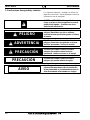 8
8
-
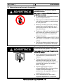 9
9
-
 10
10
-
 11
11
-
 12
12
-
 13
13
-
 14
14
-
 15
15
-
 16
16
-
 17
17
-
 18
18
-
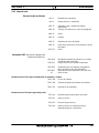 19
19
-
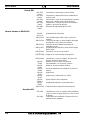 20
20
-
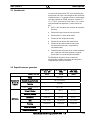 21
21
-
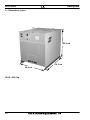 22
22
-
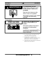 23
23
-
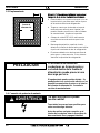 24
24
-
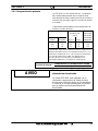 25
25
-
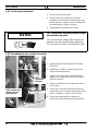 26
26
-
 27
27
-
 28
28
-
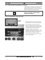 29
29
-
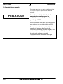 30
30
-
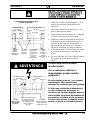 31
31
-
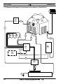 32
32
-
 33
33
-
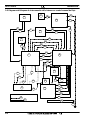 34
34
-
 35
35
-
 36
36
-
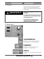 37
37
-
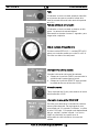 38
38
-
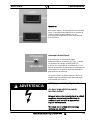 39
39
-
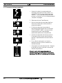 40
40
-
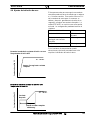 41
41
-
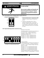 42
42
-
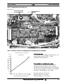 43
43
-
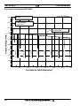 44
44
-
 45
45
-
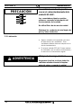 46
46
-
 47
47
-
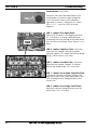 48
48
-
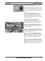 49
49
-
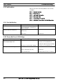 50
50
-
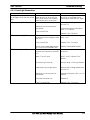 51
51
-
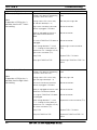 52
52
-
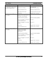 53
53
-
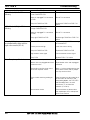 54
54
-
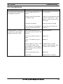 55
55
-
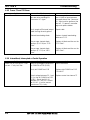 56
56
-
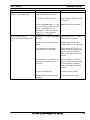 57
57
-
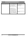 58
58
-
 59
59
-
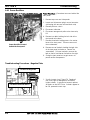 60
60
-
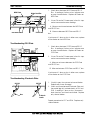 61
61
-
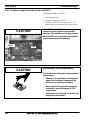 62
62
-
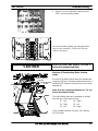 63
63
-
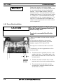 64
64
-
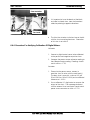 65
65
-
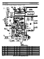 66
66
-
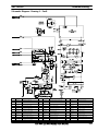 67
67
-
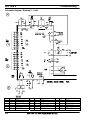 68
68
-
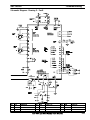 69
69
-
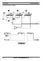 70
70
-
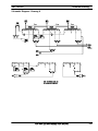 71
71
-
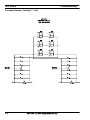 72
72
-
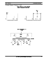 73
73
-
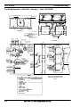 74
74
-
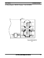 75
75
-
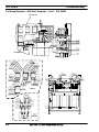 76
76
-
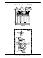 77
77
-
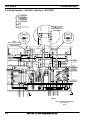 78
78
-
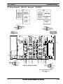 79
79
-
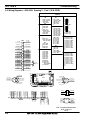 80
80
-
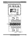 81
81
-
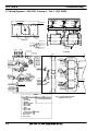 82
82
-
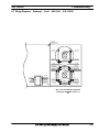 83
83
-
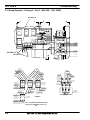 84
84
-
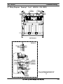 85
85
-
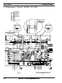 86
86
-
 87
87
-
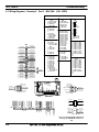 88
88
-
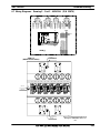 89
89
-
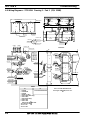 90
90
-
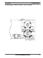 91
91
-
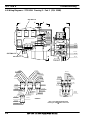 92
92
-
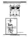 93
93
-
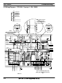 94
94
-
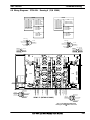 95
95
-
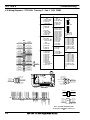 96
96
-
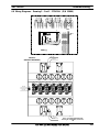 97
97
-
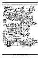 98
98
-
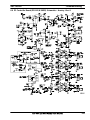 99
99
-
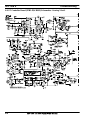 100
100
-
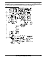 101
101
-
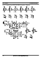 102
102
-
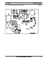 103
103
-
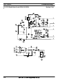 104
104
-
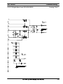 105
105
-
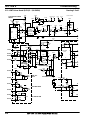 106
106
-
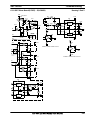 107
107
-
 108
108
-
 109
109
-
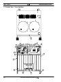 110
110
-
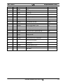 111
111
-
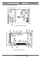 112
112
-
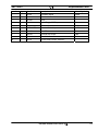 113
113
-
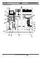 114
114
-
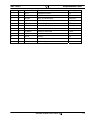 115
115
-
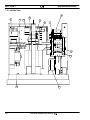 116
116
-
 117
117
-
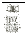 118
118
-
 119
119
-
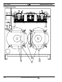 120
120
-
 121
121
-
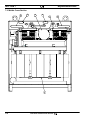 122
122
-
 123
123
-
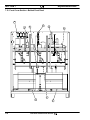 124
124
-
 125
125
-
 126
126
-
 127
127
-
 128
128


ESAB ESP-600C Manual de usuario
- Tipo
- Manual de usuario
- Este manual también es adecuado para
Artículos relacionados
-
ESAB ESP 400C Plasma Power Source Manual de usuario
-
-
-
ESAB PT-19XLS or PT-36 Manual de usuario
-
-
-
-
-
-
ESAB 100i Manual de usuario
Otros documentos
-
Adidas AVUS-10421 Manual de usuario
-
Magnetrol Thermatel TD1/TD2 Instrucciones de operación
-
 Adidas Fitness AVUS-10521 Manual de usuario
-
CAME SALOON Guía de instalación
-
-
Tunturi FitRun 90i PRO Manual Concise
-
Cooper Lighting 6- ControlKeeper 4A - CK4A Guía de instalación
-
AKO 14721 Instrucciones de operación
-
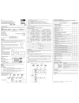 AKO Electronica AKO-14721 Installation and User Instructions
-
Robur NEXT R Installation, Use And Maintenance Manual

