DO NOT RETURN YOUR UNIT
TO THE STORE
Contact us first
www.sauder.com
Most replacement parts ship from our
facility in one or two business days.
For immediate service,
our website is available
24 hours a day, 7 days a week
to order replacement parts,
access assembly tips,
register your product,
and view Sauder products.
Mon-Fri -- 9am-5:30pm ET
United States and Canada (except holidays)
Consumer Services 1--800--523--3987
Lateral File
register your new purchase online
www.sauder.com
Assembly Instructions
09 / 30/ 11
Lot #: 340566
Date Purchased:
Record the date you purchased this unit and save the booklet
for future reference.
If you ever need to contact Sauder about this unit, refer to the
lot # and the model # when calling our toll-free number. For more
information about our furniture, company, or to order replacement
parts, please visit our web site.
Model # 101702
This instruction booklet contains important safety information.
Please read and keep for future reference.
NOTE
register your new purchase online
www.sauder.com
The center pages of this book are French and Spanish
instructions.
Les instructions en français et en espagnol sont situées
dans liencart au milieu de ce manuel. Pour plus de
commodité, celles-ci sont facilement détachables.
Se incluyen las instrucciones en español y francés en el
centro de este folleto. Para facilitar su uso, se puede
desprenderlas fácilmente.
The Camden County Collection

PARTS IDENTIFICATION
101702
(A3) RIGHT
END -- 1
(B3) LEFT
END -- 1
(E) BACK -- 1
(F2) LARGE
EXTENSION
BLOCK -- 1
(G2) SMALL
EXTENSION
BLOCK -- 3
(K3) DRAWER
SIDE -- 4
(L2) DRAWER
BOTTOM -- 2
(M) TOP
MOLDING -- 1
(V) INTERLOCK
TRACK -- 1
(N) BASE -- 1
(Y) TWIST-LOCK
R
FASTENER -- 8
(W) CABINET
ACTUATOR -- 2
(X) DRAWER
ACTUATOR -- 2
(QQ) FILE
CLIP -- 8
(O2) END
MOLDING -- 2
(AA) LOCK -- 1

Each part for this unit may not have a label or inked letter on it. Parts are labeled or inked on the edge to help
distinguish similar parts from each other. Use this PARTS IDENTIFICATION to help identify similar parts.
101702
(C) TOP -- 1 (D) BOTTOM -- 1
(H2) LOCKING
DRAWER
FRONT -- 1
(I2) LOWER
DRAWER
FRONT -- 1
(J3) DRAWER
BOX
FRONT -- 4
(RR) EXTENSION
RAIL -- 4
(SS) EXTENSION
SLIDE -- 4
(Extension Set shown separated)
(CC) PULL
MOUNT -- 8
(EE) TOUCH--UP
PEN -- 1
(R) STRAIGHT
FILE GLIDE -- 4
(FF) SAFETY
BRACKET -- 1
(DD) ANGLE
BRACKET -- 4
(S) NOTCHED
FILE GLIDE -- 4
(U) ACTUATOR
LINK -- 1
(PP) FILE
ROD -- 4
(BB) PULL -- 4

ASSEMBLY TOOLS REQUIRED
HAMMER
NO. 2 PHILLIPS SCREWDRIVER
TIP SHOWN ACTUAL SIZE
AUDER WELCOMES YOU TO THE WORLD OF READY--TO-- ASSEMBLE FURNITURE
SSEMBLY IS QUITE SIMPLE IF YOU FOLLOW OUR STEP--BY--STEP INSTRUCTIONS
NPACK PARTS CAREFULLY TO PREVENT SCRATCHING OF THE FINISHED PIECES
O NOT BEGIN ASSEMBLY UNTIL YOU ARE FAMILIAR WITH THE PARTS
XTRA TIME SPENT DURING THE ASSEMBLY WILL BE WELL WORTH IT
EADY....SET....GO
S
A
U
D
E
R
CFCs
The polystyrene foam usedin Sauder
packaging contains no CFCs
which
are known to reduce stratospheric
ozone layers.
SCREWS SHOWN ACTUAL SIZE
Each time a screw is used, it is shown
actual size for you to compare w ith the
screw in your hand.
101702
(GG) 1 --7/8” PAN HEAD SCREW -- 14 (II) 1--1/4” FLAT HEAD SCREW -- 20
(KK) 9/16” LARGE HEAD SCREW -- 9
(TT) GOLD 5/16” FLAT HEAD SCREW -- 8
(OO) NAIL -- 19
ADJUSTABLE WRENCH TAPE MEASURE
(JJ) 1 --1/4” MACHINE SCREW -- 8
(LL) 1/2” FLAT HEAD SCREW -- 4
(NN) 7/16” LARGE HEAD SCREW -- 8

1
Read each step through completely before beginning the step. This box “-” is provided as a check--off box. As you
complete each task, check it off.
- To begin assembly, push a SAUDER TWIST-LOCK
R
FASTENER (Y) into the large holes in the RIGHT END (A3)
and LEFT END (B3). Repeat this step for the BOTTOM (D).
NOTE: Be sure the TWIST-LOCK
R
FASTENERS are positioned as shown in the enlarged diagrams.
Make sure the point is positioned as shown in the enlarged diagram. Do not
tighten the
TWIST-LOCK
R
FASTENERS at this time.
NOTE: If you need to remove a TWIST-LOCK
R
FASTENER from a hole, pull the FASTENER back out
of the hole. Pull at the front and back edges, slowly working the FASTENER out of the hole.
TWIST-LOCK
R
FASTENER (Y)
LEFT
END (B3)
Make sure this point
is in this location.
Dowel end
RIGHT
END (A3)
101702
www.sauder.com/services
Look for this icon. It means a video assembly tip is available at:
Repérer cette icône. Elle signifie qu’un conseil de montage vidéo est disponible à :
Busque este icono. Significa que un consejo práctico para ensamble de muebles, grabado en video, está disponible en:
www.sauder.com/services/tips

2
101702
LEFT
END (B3)
- Slide a patented* END MOLDING (O2) onto the notched edge of each END. Carefully slide both MOLDINGS
until the MOLDINGS are even with the top edge of each END.
NOTE: The MOLDINGS should overhang the surface with holes. If the MOLDING overhangs the
wrong surface, remove it and slide it on again. Slide the MOLDING off the notched edge in
the same direction that it was slid on.
* U.S. Pat. No. 5,499,886
Slide the END
MOLDING (O2) onto
the notched edge.
END
MOLDING (O2)
END
MOLDING (O2)
Slide the END
MOLDING (O2) onto
the notched edge.
RIGHT
END (A3)
These edges
should be even.
www.sauder.com/services

3
101702
- Fasten one SMALL EXTENSION BLOCK (G2) to the RIGHT END (A3) as shown. Use three 1--7/8” PAN HEAD
SCREWS (GG) through the large holes in the SMALL EXTENSION BLOCK and into the pre--drilled holes in the RIGHT END.
NOTE: DO NOT OVERTIGHTEN THE SCREWS
. Be sure the surface with five holes on the SMALL EXTENSION
BLOCK is facing up. The middle hole is not centered. Use your tape measure. This hole must be
located toward the bottom edge. Follow the diagram closely.
- Fasten two SMALL EXTENSION BLOCKS (G2) to the LEFT END (B3) as shown. Use three 1--7/8” PAN HEAD
SCREWS (GG) through the large holes in the SMALL EXTENSION BLOCKS and into the pre--drilled holes in the LEFT END.
NOTE: DO NOT OVERTIGHTEN THE SCREWS
. Be sure the surfaces with five holes on the SMALL EXTENSION
BLOCKS are facing up. The middle holes are not centered. Use your tape measure. These holes must
be located toward the bottom edge. Follow the diagram closely.
- Fasten two ANGLE BRACKETS (DD) to the RIGHT END (A3) and LEFT END (B3) as shown. Use a 9/16” LARGE HEAD
SCREW (KK) through each BRACKET and into the pre--drilled holes in the ENDS.
NOTE: Be sure to position the BRACKETS as shown. Be sure the edges of the BRACKETS are even with the
edges of the ENDS. Follow the enlarged diagrams.
RIGHT
END (A3)
LEFT
END (B3)
SMALL EXTENSION
BLOCK (G2)
9/16” LARGE HEAD SCREW (KK)
(4 used in this step)
ANGLE
BRACKET (DD)
1--7/8” PAN HEAD SCREW (GG)
(9 used in this step)
ANGLE
BRACKET (DD)
Surface with
five holes.
These holes are not
centered. They must
be located toward the
bottom edge.
Bottom
edge
www.sauder.com/services

4
101702
Follow the diagrams closely for this step. Be sure the parts are positioned as shown.
How to use the SAUDER TWIST-LOCK
R
FASTENER (Refer to th e enlarged diagram.)
1. Insert the dowel end of the FASTENER into the hole of t he adjoining part.
NOTE: The dowel end of the FASTENER must remain fully inserted in the hole
of the adjoining part while locking the FASTENER.
2. Tighten the FASTENER with a Phillips screwdriver as tight as possible.
- Fasten the TOP MOLDING (M) to the TOP (C) as shown. Use four 1--1/4” FLAT HEAD SCREWS (II) through the
TOP MOLDING and into the pre--drilled holes in the TOP.
NOTE: Be sure the finished surface of the TOP MOLDING is facing as shown.
- Fasten the LEFT END (B3) to the TOP (C) as shown. You will need to slide the END MOLDING (O2) on the LEFT
END down as you insert the TWIST-LOCK
R
FASTENERS into the holes in the TOP. Tighten the TWIST-LOCK
R
FASTENERS in the LEFT END.
NOTE: You will need to slide the END MOLDING (O2) down a little to insert the TWIST-LOCK
R
FASTENERS into the TOP. The END MOLDING should be against the TOP MOLDING (M) after
the END is fastened.
- Fasten the BOTTOM (D) to the LEFT END (B3) as shown. Tighten the TWIST-LOCK
R
FASTENERS in
the BOTTOM.
NOTE: Be sure the surface with TWIST-LOCK
R
FASTENERS on the BOTTOM is facing as shown.
TOP (C)
LEFT
END (B3)
BOTTOM (D)
Groove
END
MOLDING (O2)
TOP
MOLDING (M)
Tighten the FASTENER as tight
as possible after
inserting the
dowel end of the FASTENER into
the hole of the adjoining part.
Finished
surface
1--1/4” FLAT HEAD SCREW (II)
(4 used in this step)
Surface with
TWIST-LOCK
R
FASTENERS
www.sauder.com/services

5
101702
Flat
edge
RIGHT
END (A3)
- Fasten the RIGHT END (A3) to the TOP (C), then to the BOTTOM (D) as shown. You will need to slide the END
MOLDING (O2) on the RIGHT END down as you insert the TWIST-LOCK
R
FASTENERS into the holes in the TOP.
Tighten the TWIST-LOCK
R
FASTENERS in the RIGHT END and BOTTOM.
NOTE: You will need to slide the END MOLDING (O2) down a little to insert the TWIST-LOCK
R
FASTENERS into the TOP. The END MOLDING should be against the TOP MOLDING (M) after
the END is fastened.
- Fasten the BASE (N) to the RIGHT END (A3) and LEFT END (B3) as shown. Use a 9/16” LARGE HEAD
SCREW (KK) through each ANGLE BRACKET and into the pre--drilled holes in the BASE.
NOTE: Be sure the flat edge of the BASE is facing as shown. Follow the diagram.
TOP (C)
END
MOLDING (O2)
BOTTOM (D)
BASE (N)
9/16” LARGE HEAD SCREW (KK)
(4 used in this step)
LEFT
END (B3)
TOP
MOLDING (M)
www.sauder.com/services

6
101702
- Tap the INTERLOCK TRACK (V) into the groove in the LARGE EXTENSION BLOCK (F2) using your hammer
as shown.
NOTE: The ends of the INTERLOCK TRACK must be even with both ends of the LARGE
EXTENSION BLOCK.
INTERLOCK
TRACK (V)
The ends of the INTERLOCK
TRACK should be even with
both ends of the LARGE
EXTENSION BLOCK.
LARGE
EXTENSION
BLOCK (F2)
www.sauder.com/services

A l’usage exclusif du
Canada
Noter la date d’achat
de cet élément et
conserver le livret
pour future référence.
Pour contacter
Sauder en ce qui
concerne cet élément,
faire référence au
numéro de lot et
numéro de modèle en
appelant notre
numéro sans frais.
Ou écrire à :
Sauder Woodworking
P.O. Box 156
Archbold, Ohio 43502
É.--U.
Lot nº :
Date de
l’achat:
LISTE DE PIÈCES LISTE DE PIÈCES
Utilisez les instructions d’assemblage en français avec les
schémas étape par étape du manuel d’instruction en anglais.
Chaque étape en français correspond à la même étape en
anglais. La pièce devant être attachée à l’élément est
représentée en gris sur les schémas de chaque étape pour plus
de précision. Comparer la “Liste de pièces” ci--dessous avec la
“PARTS IDENTIFICATION” du manuel en anglais pour vous
familiariser avec les pièces avant l’assemblage.
REMARQUE
: Ce manuel d’instructions contient d’importantes
informations relatives à la sécurité. À lire et conserver pour
toute référence future.
101702
CLASSEUR LATÉRALE
DESCRIPTION QUANTITÉREFERENCE
OUTILS D’ASSEMBLAGE REQUIS
TOURNEVIS À TÊTE CRUCIFORME PHILLIPS
Nº 2 (POINTE GRANDEUR NATURE)
TOURNEVIS À POINTE DROITE
MARTEAU
DESCRIPTION QUANTITÉREFERENCE
NE PAS RAPPORTER L’ÉLÉMENT AU MAGASIN
Nous contacter en premier
www.sauder.com
Pour obtenir une service immédiate, notre site Internet
est disponible 24 heures sur 24, 7 jours sur 7,
pour commander des pièces de rechange,
des conseils d’assemblage, enregistrer tout produit
ou visualiser des produits Sauder.
Du lundi au vendredi de9h00à17h30
(heure normale de l’est)
Aux États--Unis et au Canada (sauf jours fériés)
Services aux consommateurs 1--800--523--3987
Les pièces de rechange sont, pour la plupart, expédiées
de notre établissement dans les un à deux jours ouvrables.
A3 EXTRÉMITÉ DROITE 1
B3 EXTRÉMITÉ GAUCHE 1..................
C DESSUS 1
D DESSOUS 1............................
E ARRIÈRE 1
F2 GRAND BLOC D’EXTENSION 1...........
G2 PETIT BLOC D’EXTENSION 3
H2 DEVANT DE TIROIR VERROUILLABLE 1...
I2 DEVANT DE TIROIR INFÉRIEUR I
J3 DEVANT DE CAISSON DE TIROIR 4.......
K3 CÔTÉ DE TIROIR 4
L2 FOND DE TIROIR 2......................
M MOULURE DE DESSUS 1
NSOCLE 1...............................
O2 MOULURE D’EXTRÉMITÉ 2
RR GLISSIÈRE D’EXTENSION 4..............
SS COULISSE D’EXTENSION 4
Ensemble de extension illustré à part
R ARMATURE DROITE POUR DOSSIERS 4..
S ARMATURE CRANTÉE POUR DOSSIERS 4
PP GUIDE POUR DOSSIERS 4...............
U BRAS DE ACTIONNEUR 1
V RAIL DE VERROUILLAGE 1..............
W ACTIONNEUR D’ÉLÉMENT 2
X ACTIONNEUR DE TIROIR 2..............
Y FIXATION TWIST–LOCKR 8
QQ CLIP POUR DOSSIERS 8
AA SERRURE 1............................
BB POIGNÉE 4
CC MONTURE DE POIGNÉE 8...............
DD CONSOLE À ÉQUERRE 4
EE FEUTRE DE RETOUCHE 1...............
FF CONSOLE DE SÉCURITÉ 1
AUTOCOLLANT AVEC LOGO SAUDER 1...
Décoller le film protecteur et placer l’autocollant à l’intérieur
du tiroir ou de porte. Choisir l’emplacement de l’autocollant
avec précaution parce que sa position sera permanente.
GG VIS TÊTE GOUTTE DE SUIF 48 mm 14.....
II VIS TÊTE PLATE 32 mm 20
JJ VIS À MÉTAUX 32 mm 8..................
KK VIS TÊTE LARGE 14 mm 9
LL VIS TÊTE PLATE 13 mm 4................
TT VIS DORÉE TÊTE PLATE 8 mm 8
NN VIS TÊTE LARGE 11 mm 8...............
OO CLOU 19

101702 Fr
ÉTAPE 2
GARANTIE LIMITÉE SUR 5 ANS
1. Les meubles Sauder
R
sont garantis par Sauder W oodworking Co.
(Sauder) au pr ofit de l’acheteur original pendant une période de cinq ans à
partir de la date d’achat contre tout défaut dans les matériaux ou vice de
fabrication concernant les pièces des meubles. Le mot « défauts » tel qu’il est
utilisé sous les termes de cette garantie compr end les imperfections des pièces
qui empêchent substantiellement l’utilisation du produit.
2. En vertu de la présente garantie, Sauder réparera ou remplacera, à sa
seule discrétion, toute pièce de meuble défectueuse. Comme condition du
remplacement de la pièce jugée défectueuse, Sauder peut exiger une
confirmation indépendante du défaut allégué. Les pièces de rechange
seront garanties uniquement pendant la période restante de la garantie
originale. La présente garantie ne couvre pas le coût du montage ou
démontage, le transport, la main d’œuvre ou les autres frais imprévus
impliqués dans la dépose d’une pièce défectueuse ou l’installation de la
pièce de rechange.
3. Cette garantie s’applique dans les cas d’utilisation normale
uniquement. La présente garantie ne saurait couvrir les défauts qui
surviendraient à la suite d’un accident, d’une mauvaise utilisation ou d ’un
abus, d’un dommage intentionnel, d’un incendie, d’une inondation, d’une
altération ou modification du produit, de négligence , d’exposition ou
d’utilisation du produit allant à l’enc ontre de son usage prévu. Sauder ne
sera en aucun cas responsable des frais de réparation ou de
remplacement de tout article ayant été placé dans, sur ou à proximité de
tout mobilier Sauder.
4. La présente garantie ne s’applique que tant que le produit continue
d’être la propriété de l’acheteur original. La garantie ne peut pas être
transférée à des p ropriétaires ou utilisateurs subséquents du produit, et
sera immédiatement invalidée dans le cas où le produit est revendu,
transféré, loué sous bail ou loué à une tierce partie ou personne autre que
l’acheteur original.
5. IL N’EXISTE PAS DE GARANTIES EXPRESSES AUTRES QUE
CELLES INDIQUÉES CI--DESSUS. EN OUTRE, AUCUNE GARANTIE
IMPLICITE Y COMPRIS, MAIS NON DE FAÇON LIMITATIVE, TOUTE
GARANTIE IMPLICITE DE COMMERCIABILITÉ OU D’ADAPTATION
À UN USAGE PARTICULIER, NE S’ÉTENDRA AU--DELÀ DU TERME
DE LA PRÉSENTE GARANTIE EXPRESSE. Ce rtains états ne permettant
pas que des limites soient imposées quant à la durée d’une garantie
implicite, la limite ci --dessus peut donc ne pas être applicable. SAUDER
NE SERA EN AUCUN CAS RESPONSABLE ENVERS QUICONQUE
POUR PERTE DE PROFIT OU POUR TOUT AUTRE DOMMAGE
SPÉCIAL, CONSÉCUTIF, INDIRECT, EXEMPLAIRE OU ACCESSOIRE
DE TOUTE SORTE QUELLE QU’EN SOIT SA PROVENANCE,
CONTRAT, DÉLIT, RESPONSABILITÉ DU PRODUIT OU AUTRE.
Certains états ou provinces ne permettant pas l’exclusion ou la limite aux
responsabilités pour dommages acc identels ou consécutifs, la limite ou
l’exclusion ci--dessus peut ne pas être applicable. La présente garantie
vous donne des droits légaux spécifiques et il est possible que vous ayez
des droits supplémentaires variant d’état en état ou de province en
province. En dehors des États--Unis, les dro its légaux spécifiques peuvent
varier en fonction du pays de résidence de l’acheteur original.
6. Pour toute question concernant la garantie ou toute d emande de
réclamation, contactez Sauder en composant le 1--800 --523-- 3987, en
adressant un courrier électronique à www.sauder.com
ou bien encore en
envoyant une télécopie au 419--446--3444. Sauder peut exiger de
soumettre les demandes de réclamation sous garantie par écrit à Sauder
Woodworking Co., 502 Middle Street, Archbold, OH 43502 USA. Veuillez
joindre v otre ticket de caisse ou toute autre preuve d’achat ainsi qu’une
description spécifique du défaut de produit.
ÉTAPE 1
Pour commencer l’assemblage, enfoncer une
FIXATION TWIST--LOCKR SAUDER (Y) dans les
gros trous dans l’EXTRÉMITÉ DROITE (A3) et
l’EXTRÉMITÉ GAUCHE (B3). Répéter cette étape
pour le DESSOUS (D).
REMARQUE : S’assurer de placer les FIXATIONS
TWIST--LOCKR exactement comme l’indiquent
les schémas agrandis. S’assurer de placer la
pointe comme l’indique le schéma agrandi.
Ne
pas
serrer les FIXATIONS TWIST–LOCKR àce
stade de l’assemblage.
REMARQUE : Pour retirer une FIXA TION
TWIST--LOCKR d’un trou, il suffit de tirer la
FIXATION hors du trou. Tirer sur les bords avant et
arrière et faire sortir lentement la FIXATION du trou.
Enfiler une MOULURE D’EXTRÉMITÉ (O2) sur le
chant cranté de chaque EXTRÉMITÉ.Avec
précaution, enfiler les deux MOULURES jusqu’à ce
que les MOULURES soient à fleur du chant supérieur
de chaque EXTRÉMITÉ.
REMARQUE : Les MOULURES devraient
dépasser de la surface comportant les trous. Si la
MOULURE dépasse du mauvais côté, l’enlever et
l’enfiler à nouveau. Retirer la MOULURE du chant
crantée en la faisant glisser dans le même sens
où elle a été posée.

101702 Fr
ÉTAPE 3 ÉTAPE 4
Fixer un PETIT BLOC D’EXTENSION (G2) à
l’EXTRÉMITÉ DROITE (A3) comme l’indique le
schéma. Utiliser trois VIS TÊTE GOUTTE DE SUIF
48 mm (GG) à travers les gros trous dans le PETIT
BLOC D’EXTENSION et dans les trous pré--percés
dans l’EXTRÉMITÉ DROITE.
REMARQUE : NE PAS TROP SERRER LES
VIS.
S’assurer que la surface comportant cinq trous
sur le PETIT BLOC D’EXTENSION est dirigée vers
le haut. Le trou du milieu n’est pas centré. Utiliser
le mètre à ruban. Ce trou devrait être situé vers le
chant inférieur. Suivre attentivement les
indications du schéma.
Fixer deux PETITS BLOCS D’EXTENSION (G2) à
l’EXTRÉMITÉ GAUCHE (B3) comme l’indique le
schéma. Utiliser trois VIS TÊTE GOUTTE DE SUIF
48 mm (GG) à travers les gros trous dans les
PETITS BLOCS D’EXTENSION et dans les trous
pré--percés dans l’EXTRÉMITÉ GAUCHE.
REMARQUE : NE PAS TROP SERRER LES
VIS.
S’assurer que les surfaces comportant cinq trous
dans les PETITS BLOCS D’EXTENSION sont
dirigées vers le haut. Les trous du milieu ne sont
pas centrés. Utiliser le mètre à ruban. Ces trous
devraient être situés vers le chant inférieur.
Suivre attentivement les indications du schéma.
Fixer deux CONSOLES À ÉQUERRE (DD) à
l’EXTRÉMITÉ DROITE (A3) et à l’EXTRÉMITÉ
GAUCHE (B3) comme l’indique le schéma. Utiliser
une VISTÊTELARGE14mm(KK)à travers chaque
CONSOLE et dans les trous pré--percés des
EXTRÉMITÉS.
REMARQUE : S’assurer de placer les
CONSOLES comme l’indique le schéma.
S’assurer que les chants des CONSOLES sont à
fleur des chants des EXTRÉMITÉS. Suivre les
indications des schémas agrandis.
Suivre attentivement les indications des schémas
pour cette étape. S’assurer de placer les pièces
exactement comme l’indique le schéma.
Utilisation de la FIXATION TWIST--LOCK
R
SAUDER (Consulter le schéma agrandi.)
1. Insérer l’extrémité filetée de la FIXATION dans
le trou de la pièce attenante.
REMARQUE : L’extrémité filetée de la FIXATION
doit rester complètement insérée dans le trou de
la pièce attenante lorsque l’on bloque la
FIXATION.
2. Bien serrer la FIXATION à l’aide d’un tournevis
Phillips.
Fixer la MOULURE DE DESSUS (M) au DESSUS (C)
comme l’indique le schéma. Utiliser quatre VIS TÊTE
PLATE 32 mm (II) à travers la MOULURE DE
DESSUS et dans les trous pré--percés du DESSUS.
REMARQUE : S’assurer que la surface finie de la
MOULURE DE DESSUS est dirigée comme
l’indique le schéma.
Fixer l’EXTRÉMITÉ GAUCHE (B3) au DESSUS (C)
comme l’indique le schéma. Il faut d’enfiler la
MOULURE D’EXTRÉMITÉ (O2) située sur
l’EXTRÉMITÉ GAUCHE vers le bas lorsque l’on
insère les FIXATIONS TWIST--LOCKR dans les
trous du DESSUS. Serrer les FIXATIONS
TWIST--LOCKR dans l’EXTRÉMITÉ GAUCHE.
REMARQUE : Il faudra enfiler la MOULURE
D’EXTRÉMITÉ (O2) légèrement pour insérer les
FIXATIONS TWIST--LOCKR dans le DESSUS. La
MOULURE D’EXTRÉMITÉ devrait être plaquée
contre la MOULURE DE DESSUS (M) une fois
l’EXTRÉMITÉ fixée.
Fixer le DESSOUS (D) à l’EXTRÉMITÉ GAUCHE (B3)
comme l’indique le schéma. Serrer les FIXATIONS
TWIST--LOCKR dans le DESSOUS.
REMARQUE : S’assurer que la surface
comportant les FIXATIONS TWIST--LOCKR
situées sur le DESSOUS est dirigée comme
l’indique le schéma.

101702 Fr
ÉTAPE 8
ÉTAPE 5 ÉTAPE 7
Fixer l’EXTRÉMITÉ DROITE (A3) au DESSUS (C) et
ensuite au DESSOUS (D) comme l’indique le
schéma. Il faut d’enfiler la MOULURE
D’EXTRÉMITÉ (O2) située sur L’EXTRÉMITÉ
DROITE vers le bas lorsque l’on insère les
FIXATIONS TWIST--LOCKR dans les trous du
DESSUS. Serrer les FIXATIONS TWIST--LOCKR
dans l’EXTRÉMITÉ DROITE et le DESSOUS.
REMARQUE : Il faudra enfiler la MOULURE
D’EXTRÉMITÉ (O2) légèrement pour insérer les
FIXATIONS TWIST--LOCKR dans le DESSUS. La
MOULURE D’EXTRÉMITÉ devrait être plaquée
contre la MOULURE DE DESSUS (M) une fois
l’EXTRÉMITÉ fixée.
Fixer le SOCLE (N) à l’EXTRÉMITÉ DROITE (A3) et
à l’EXTRÉMITÉ GAUCHE (B3) comme l’indique le
schéma. Utiliser une VISTÊTELARGE14mm(KK)
à travers chaque CONSOLE À ÉQUERRE et dans
les trous pré--percés dans le SOCLE.
REMARQUE : S’assurer que le chant plat du
SOCLE est dirigé comme l’indique le schéma.
Suivre les indications du schéma.
Fixer les deux ACTIONNEURS D’ÉLÉMENT (W) au
BRAS D’ACTIONNEUR (U) comme l’indique le
schéma du haut. Enfoncer une tige dans chaque
ACTIONNEUR D’ÉLÉMENT à travers les trous dans
lesextrémitésduBRAS D’ACTIONNEUR.
Pour assurer la opération aise du système de
verrouillage, il est recommandé de utiliser de
l’encaustique pour meubles pour lubrifier l’intérieur du
RAIL DE VERROUILLAGE. Suivre les indications du
schéma.
Maintenant, enfiler les ACTIONNEURS D’ÉLÉMENT et
le BRAS D’ACTIONNEUR dans le RAIL DE
VERROUILLABLE comme l’indique le schéma du bas.
Glisser dans tout le RAIL plusieurs fois pour étaler
l’encaustique complètement.
REMARQUE : Le système de verrouillage
empêche d’ouvrir plus d’un tiroir à la fois. Ne pas
trop forcer pour étendre les tiroirs.
Avec précaution, retourner l’élément sur
l’EXTRÉMITÉ DROITE (A3).
Fixer le GRAND BLOC D’EXTENSION (F2) à
l’EXTRÉMITÉ DROITE (A3) comme l’indique le
schéma. Utiliser quatre VIS TÊTE GOUTTE DE SUIF
48 mm (GG) à travers les gros trous dans le GRAND
BLOC D’EXTENSION et dans les trous pré--percés
dans l’EXTRÉMITÉ DROITE.
REMARQUE : Ne pas trop serrer les VIS. S’assurer
que la surface comportant six trous du GRAND
BLOC D’EXTENSION est dirigée vers le haut. Suivre
attentivement les indications du schéma.
ÉTAPE 6
Enfoncer le RAIL DE VERROUILLAGE (V) dans la
rainure du GRAND BLOC D’EXTENSION (F2) à
l’aide de un marteau.
REMARQUE : Les extrémités du RAIL DE
VERROUILLAGE devraient être à fleur des
extrémités du GRAND BLOC D’EXTENSION.

101702 Fr
ÉTAPE 9 ÉTAPE 10
STOP : NE PAS relever l’élément dans sa position
verticale avant d’avoir fixé l’ARRIÈRE. L’élément
risque de s’effondrer.
Avec précaution, retourner l’élément sur ses chants
avant. Déplier l’ARRIÈRE (E) et le placer sur
l’élément.
REMARQUE : S’assurer de placer le chant cranté
de l’ARRIÈRE comme l’indique le schéma.
S’assurer que le chant inférieur de l’ARRIÈRE est
à fleur du chant inférieur du DESSOUS (D). Suivre
les indications du schéma.
POUR CLOUER L’ARRIÈRE :
1º: Enfoncer un CLOU (OO) dans la rangée de trous
le long du chant supérieur de l’ARRIÈRE (E).
2º: S’assurer que la marge tout autour des deux
chants latéraux de l’ARRIÈRE est régulière. Ceci
permet d’être sur que l’élément est “d’équerre”.
3º: Ensuite, enfoncer un CLOU dans la rangée de
trous le long du chant inférieur de l’ARRIÈRE.
Continuer de fixer l’ARRIÈRE (E) à l’élément à l’aide
des CLOUS (OO).
Relever , avec précaution, l’élément dans sa position
verticale.
Séparer les COULISSES D’EXTENSION (SS) des
GLISSIÈRES D’EXTENSION (RR). Pour cela, tirer
au maximum la COULISSE D’EXTENSION et
appuyer sur le levier de blocage noir qui se trouve
sur la COULISSE. Maintenant, sortir la COULISSE
de la GLISSIÈRE de façon à obtenir deux pièces
indépendantes. Faire attention car les pièces sont
graissées.
S’assurer que la cartouche interne de chaque
GLISSIÈRE D’EXTENSION (RR) (les roulements à
billes y compris) est complètement étirée comme
l’indique le schéma. Fixer deux GLISSIÈRES
D’EXTENSION aux BLOCS D’EXTENSION dans
chaque EXTRÉMITÉ, comme l’indique le schéma, en
utilisant deux VIS DORÉE TÊTE PLATE 8 mm à
travers chaque GLISSIÈRE D’EXTENSION et dans
les petits trous dans les BLOCS D’EXTENSION.
Consulter la note ci--dessous pour plus instructions.
REMARQUE : Pour chaque GLISSIÈRE
D’EXTENSION, faire tourner une VIS dans le trou
indiqué dans le schéma agrandi à la droite.
Enfiler ensuite la cartouche interne de la
GLISSIÈRE D’EXTENSION vers l’intérieur pour
trouver l’autre trou qui est aligné sur le trou dans
le BLOC D’EXTENSION. Faire tourner une VIS
dans ce trou.
REMARQUE : Un ACTIONNEUR D’ÉLÉMENT (W)
devrait être situé au--dessus de chaque
GLISSIÈRE sur l’EXTRÉMITÉ DROITE (A3).
Vérifier l’emplacement des ACTIONNEURS
D’ÉLÉMENT avant de fixer les GLISSIÈRES
D’EXTENSION aux BLOCS D’EXTENSION.

101702 Fr
ÉTAPE 11 ÉTAPE 12
Fixer deux CÔTÉSDETIROIR(K3)à l’un des
DEVANTS DE CAISSON DE TIROIR (J3). Utiliser
deux VIS TÊTE PLATE 32 mm (II) à travers les trous
dans chaque CÔTÉ DE TIROIR et dans les trous
dans les chants du DEVANT DE CAISSON DE
TIROIR.
REMARQUE : S’assurer que les rainures de
chaque pièce s’alignent les unes sur les autres à
l’intérieur du tiroir.
Enfiler un FOND DE TIROIR (L2) dans les rainures
des CÔTÉSDETIROIRet du DEVANT DE
CAISSON DE TIROIR.
REMARQUE : S’assurer que la surface finie du
FOND DE TIROIR est dirigée vers le haut.
Fixer un autre DEVANT DE CAISSON DE TIROIR (J3)
aux CÔTÉSDETIROIR(K3). Utiliser quatre VIS TÊTE
PLATE 32 mm (II) à travers les trous dans les CÔTÉS
DE TIROIR et dans les trous dans les chants du
DEVANT DE CAISSON DE TIROIR.
REMARQUE : S’assurer que le FOND DE TIROIR
s’encastre dans la rainure du DEVANT DE
CAISSON DE TIROIR.
Appuyer une ARMATURE CRANTÉE POUR
DOSSIERS (S) sur les deux CÔTÉS DE
TIROIR (K3) de l’un des tiroirs. Enfoncer une
ARMATURE DROITE POUR DOSSIERS (R) sur l
es
deux DEVANTS DE CAISSON DE TIROIR (J3). Les
ARMATURES POUR DOSSIERS sont
indispensables pour suspendre les dossiers.
Les tiroirs pour dossiers sont conçus pour recevoir
des dossiers de format lettre, légal ou européen.
Pour suspendre des dossiers d e format lettre ou
européen, utiliser les CLIPS POUR DOSSIERS (QQ)
et les GUIDES POUR DOSSIERS (PP). Insérer la
GUIDE POUR DOSSIERS (PP) dans chaque CLIP
POUR DOSSIERS et enfiler les CLIPS POUR
DOSSIERS sur les ARMATURES POUR
DOSSIERS (R) au besoin. Suivre les indications du
schéma.
REMARQUE : Pour suspendre les dossiers de
format lettre et européen, utiliser les GUIDES DE
DOSSIER (PP) et les ARMATURES CRANTÉES
POUR DOSSIERS (S).
Pour suspendre des dossiers d e format légal, utiliser
les ARMATURES DROITES POUR DOSSIERS (R).
Répéter cette étape pour l’autre tiroir.
Une portion agrandie du DEVANT DE TIROIR
VERROUILLABLE (H2) est représente à cette étape.
Fixer la SERRURE (AA) au DEVANT DE TIROIR
VERROUILLABLE (H2) dans l’ordre exact indiqué. Il
est important de vérifier que la CAME soit dirigée
exactement comme l’indique le schéma. En tout cas,
la clé doit tourner dans le sens contraire des aiguilles
d’une montre d’un quart de tour pour verrouiller
correctement. L a CAME devrait tourner vers le haut
une fois verrouillée.
REMARQUE : Si la serrure ne tourne pas dans le
sens contraire des aiguilles d’une montre, faire la
tourner dans le sens des aiguilles d’une montre
et fixer la CAME exactement comme l’indique le
schéma.
REMARQUE : Une fois le tiroir verrouillé, la
CAME d evrait d’insérer dans la rainure dans la
surface inférieure du DESSUS (C).

101702 Fr
ÉTAPE 13 ÉTAPE 14
Insérer une MONTURE DE POIGNÉE (CC) dans l’un
des trous dans le DEVANT DE TIROIR
VERROUILLABLE (H2). Insérer une extrémité d e
une POIGNÉE (BB) dans le trou dans cette
MONTURE DE POIGNÉE. Insérer l’autre extrémité
de la POIGNÉE dans une autre MONTURE DE
POIGNÉE et l’insérer dans l’autre trou dans le
DEVANT DE TIROIR VERROUILLABLE (H2).
Maintenant, fixer les MONTURES DE POIGNÉE au
DEVANT DE CAISSON DE TIROIR (J3). Utiliser
quatre VIS À MÉTAUX 32 mm (JJ) à travers les
trous dans le DEVANT DE CAISSON DE TIROIR et
dans les MONTURES DE POIGNÉE sur le DEVANT
DE TIROIR VERROUILLABLE.
REMARQUE : S’assurer de placer le gros trou
dans le DEVANT DE TIROIR VERROUILLABLE
comme l’indique le schéma. Le DEVANT DE
TIROIR devrait dépasser plus du chant supérieur
du tiroir. Ne pas
trop serrer les VIS. Suivre
attentivement les indications du schéma.
Fixer une COULISSE D’EXTENSION (SS) sur
chaque CÔTÉ DE TIROIR (K3) comme l’indique le
schéma.Utiliser une VISTÊTELARGE8mm(TT)
dans les trous no 1 et n o3àpartirdel’extrémité
ouverte dans chaque COULISSE D’EXTENSION et
dans les trous exacts pré-percés indiqués dans le
CÔTÉ DE TIROIR.
REMARQUE : S’assurer que les extrémités
ouvertes des COULISSES D’EXTENSION soient
dirigées vers l’arrière du tiroir.
Fixer un ACTIONNEUR DE TIROIR (X) au CÔTÉ DE
TIROIR (K3) droit comme l’indique le schéma. Utiliser
deux VIS TÊTE PLATE 13 mm (LL) à travers les
trous indiqués et dans les trous pré--percés dans le
CÔTÉ DE TIROIR.
REMARQUE : S’assurer de placer le
ACTIONNEUR DE TIROIR exactement comme
l’indique le schéma. S’assurer de bien utiliser les
deux trous exacts indiqués. Suivre attentivement
les indications du schéma agrandi.
Répéter cette étape pour l’autre tiroir.
Avant d’insérer les tiroirs dans l’élément, s’assurer
que les chants inférieurs des ACTIONNEURS
D’ÉLÉMENT (W) sont d’environ 6 mm au--dessus les
chants supérieurs des GLISSIÈRES situées sur
l’EXTRÉMITÉ DROITE (A3). Suivre attentivement le
schéma droit.
REMARQUE : Les ACTIONNEURS D’ÉLÉMENT
devraient être aux mêmes emplacements pour
retirer les tiroirs.
Pour insérer un tiroir dans l’élément, aligner les
COULISSES D’EXTENSION (SS) situées sur le tiroir
sur les GLISSIÈRES D’EXTENSION (RR) situées
sur l’élément et enfoncer le tiroir dans l’élément
jusqu’à ce que le tiroir soit complètement inséré. Le
tiroir offrira une certaine résistance jusqu’à ce qu’il
soit complètement inséré dans l’élément, il glissera
ensuite sans difficulté.
REMARQUE : Les DEVANTS DE TIROIR ont
peut--être besoin d’être ajustés. Pour ajuster les
DEVANTS DE TIROIR, desserrer les VIS qui
maintiennent les DEVANTS DE TIROIR et les
POIGNÉES aux DEVANTS DE CAISSON DE
TIROIR. Ajuster et resserrer les VIS.
Il est recommandé d’utiliser la CONSOLE DE
SÉCURITÉ (FF) fournie, surtout avec jeunes enfants.
Pour accroître la stabilité de l’élément, utiliser la
CONSOLE pour fixer le coin arrière inférieur de
l’élément au mur ou sol. Utiliser une VIS TÊTE
LARGE 14 mm (KK) à travers l’un des trous dans le
bras plus long de la CONSOLE et dans l’élément.
L’élément n’a pas de trous. Ensuite, utiliser une VIS
TÊTE PLATE 48 mm (GG) pour fixer la CONSOLE
DE SÉCURITÉ au sol, à la plinthe ou dans le mur. Si
cela ne convient pas, consulter un quincaillier pour
trouver l’attache particulière au mur.
ATTENTION : Remplir le tiroir du bas en premier
et le tiroir du haut en dernier. Placer les objets les
plus lourds dans le tiroir du bas. Vider les tiroirs
dans l’ordre inverse. Toujours vider et verrouiller
les tiroirs avant de déplacer l’élément. Le
système de verrouillage empêche d’ouvrir plus
d’un tiroir à la fois.
Pour un entretien à long terme de l’élément, il est
possible de retoucher les chants à l’aide du FEUTRE
DE RET O UCHE (EE).
Ceci complète l’assemblage. Utiliser de l’encaustique
pour meubles sur toutes les surfaces finies afin de
faire ressortir la beauté et le grain du bois. Ne pas
pulvériser de l’encaustique directement sur le
meuble. Pulvériser de l’encaustique sur un chiffon et
utiliser ensuite le chiffon pour essuyer la surface.

101702 Fr
Avertissement
Prière d’utiliser le mobilier à bon escient et avec
prudence. Une mauvaise utilisation peut être à
l’origine de risques d’accident ou peut
endommager le mobilier et les articles ménagers.
Lire attentivement le t ableau suivant.
À surveiller :
Tiroirs de caisson surchargés.
Danger éventuel :
Risque de blessure.
Caissons surchargés du haut peuvent basculer.
Des tiroirs surchargés risquerait de casser.
Solution :
Ne jamais excéder les limites de poids indiquées
dans les instructions.
Pour charger les tiroirs, commencer par remplir celui
du bas pour finir par celui du haut.
Placer les objets les plus lourds dans le tiroir inférieur .
À surveiller :
Déplacement inadéquat d’un mobilier qui n’est pas
conçu pour avoir des roulettes et n’en est pas équipé.
Danger éventuel :
Le mobilier risque de se renverser ou de casser en
cas de déplacement inadéquat.
Blessure physique. Le mobilier peut être très lourd.
Solution :
Décharger les tiroirs en commençant par celui du
haut avant de déplacer le caisson.
Ne pas pousser le mobilier , surtout sur la moquette. Se
faire aider par une autre personne pour soulever
l’élément et le mettre en place.

Anote la fecha de
comprar esta unidad y
guarde el folleto para
su referencia futura.
Si necesita ponerse
en contacto con
Sauder en cuanto a
esta unidad, refiérase
al número de lote y al
número de modelo
cuando llame a
nuestro número
gratis.
No. Lote:
Fecha
de compra:
LISTA DE PARTES LISTA DE PARTES
Use estas instrucciones de ensamblaje en español junto con
las figuras paso-a-paso provistas en el folleto inglés. Cada
paso en español corresponde al mismo paso en inglés. Se
destacan las figuras de cada paso con una tonalidad oscura
para mostrar precisamente cual parte se debe montar a la
unidad. Compare la “Lista de Partes” abajo con la “Parts
Identification” en el folleto en inglés para familiarizarse con las
partes de ensamblaje.
NOTA
: Este folleto de instrucciones contiene información
importante
sobre la seguridad. Por favor lea y guárdelo para
referencia en el futuro.
1702-100
ARCHIVERO LATERAL
DESCRIPCIÓN CANTIDADITEM DESCRIPCIÓN CANTIDADITEM
NO DEVUELVA SU UNIDAD A LA TIENDA
Comuníquese con nosotros primero
www.sauder.com
Para el servicio inmediata, nuestro sitio Web está
disponible las 24 horas al día,
7 días a la semana para pedir piezas de repuesto,
consejos de ensamblaje, registrar su producto y
ver los productos Sauder.
De lunes a viernes de 9 a.m. a 5:30 p.m. (hora del este)
Estados Unidos y Canadá (salvo días festivos)
Servicios del consumidor 1--800--523--3987
La mayoría de piezas de repuesto son enviadas desde
nuestra instalación en uno o dos días laborables.
A3 EXTREMO DERECHO 1
B3 EXTREMO IZQUIERDO 1.................
C PANEL SUPERIOR 1
D FONDO 1...............................
EDORSO 1
F BLOQUE DE EXTENSIÓN GRANDE 1.....
G BLOQUE DE EXTENSIÓN PEQUEÑO 3
H2 CARA DE CAJÓN CON CERRADURA 1....
I2 CARA DE CAJÓN INFERIOR I
J3 FRENTE DE CAJÓN 4....................
K3 LADO DE CAJÓN 4
L2 FONDO DE CAJÓN 2....................
M MOLDURA DE PANEL SUPERIOR 1
N BASE 1.................................
O2 MOLDURA DE EXTREMO 2
Juego de extensión mostrado separado
R CORRIMIENT O RECTO DE ARCHIVERO 4...
S CORRIMIENTO CON MUESCA
DE ARCHIVERO 4
RR VARILLA DE ARCHIVO 4.................
U BRAZO DE ACTUADOR 1
V CARRIL DE UNIÓN 1.....................
W ACTUADOR DE GABINETE 2
X ACTUADOR DE CAJÓN 2................
Y SUJETADOR TWIST–LOCKR 8
SS GRAPA DE ARCHIVO 8
AA CERRADURA 1.........................
BB TIRADOR 4
CC MONTAJE DE TIRADOR 8................
DD SOPORTE ANGULAR 4
EE PLUMA DE RETOQUE 1..................
FF SOPORTE DE SEGURIDAD 1
ETIQUETA CON LOGO SAUDER 1........
Separe el papel protector y adhiera las etiquetas al interior
de un cajón o una puerta. Considere cuidadosamente la
colocación porque el adhesivo es permanente.
GG TORNILLO DE CABEZA REDONDA
DE 48 mm 14
II TORNILLO DE CABEZA PERDIDA
DE 32 mm 20
JJ TORNILLO PARA METAL DE 32 mm 8.....
KK TORNILLO DE CABEZA GRANDE
DE 14 mm 9
LL TORNILLO DE CABEZA PERDIDA
DE 13 mm 4.............................
TT TORNILLO DORADO DE CABEZA PERDIDA
DE 8 mm 8
NN TORNILLO DE CABEZA GRANDE
DE 11 mm 8.............................
OO CLAVO 19

101702 Sp
PASO 2
GARANTÍA LIMITADA POR 5
AÑOS
1. Los muebles de Sauder
R
están garantizados por Sauder Woodworking
Co. (Sauder) al comprador original por un período de cinco años a partir
de la fecha de compra, contra defectos en los materiales o mano de obra
en lo que se refiere a los componentes de los muebles. La palabra
“defectos” como ha sido utilizada en e sta Garantía está definida como
imperfecciones las cuales impiden utilizar el producto.
2. Bajo esta Garantía, Sauder (a su opción únicamente) reparará o
reemplazará un componente defectuoso de mobiliario. Como condición
de proporcionar un reemplazo de un componente e l c ual ha sido
denunciado como defectuoso, Sauder podría solicitar confirmación
independiente del defecto reclamado. Las piezas de repuesto serán
garantizadas solamente por el período de tiempo que queda de la
Garantía original. Esta Garantía no cubre el costo de ensamblaje o
desmontaje, transporte, mano de obra, ni cualquier otros costos
incidentales en cuanto al retiro de una pieza defectuosa ni la instalación
de la pieza de repuesto.
3. Esta Garantía es aplicable bajo las condiciones de uso normal
solamente. Esta Garantía no se aplica a los defectos que resulten por
accidente, mal uso o abuso, daño intencional, incendio, inundación,
alteración o modificación de l producto, negligencia, exposic ión, o uso del
producto de una manera inconsistente con su uso intencionado. Sauder
no será responsable por cualquier costo de reparar o reemplazar
cualquier artículo puesto sobre, dentro, o alrededor de cualquier
producto mobiliario de Sauder.
4. Esta Garantía es válida solamente mientras que el producto continúe
siendo propiedad del comprador original y solamente sea usado por éste.
La Garantía no puede ser transferida a propietarios o usuarios del
producto posteriores, y será inmediatamente inválida en e l c aso que el
producto sea revendido, transferido, alquilado a cualquier tercero o
persona distinta al comprador original.
5. NO EXISTEN NINGUNAS OTRAS GARANTÍAS EXPRESAS SALVO LA
QUE SE CITA ARRIBA. ADEMÁS, NINGUNA GARANTÍA IMPLÍCITA,
INCLUSO, PERO NO LIMITADA A, CUALQUIER GARANTÍA
IMPLÍCITA DE COMERCIALIZACIÓN O CAPACIDAD PARA UN
PROPÓSITO ESPECÍFICO, DEBE EXTENDER MÁS ALLÁ DEL
TÉRMINO DE ESTA GARANTÍA EXPRESA. Algunos estados no permiten
la limitación de la durac ión de una garantía implícita, por eso la
limitación arriba citada pueda no ser aplicable a usted. SAUDER NO
TENDRÁ NINGUNA RESPONSABILIDAD A NINGUNA PERSONA POR
GANANCIAS PERDIDAS O POR CUALQUIER DAÑO ES PECIAL,
CONSECUENTE, INDIRECTO, EJEMPLAR O INCIDENTAL DE
CUALQUIER FORMA YA SEA SI RESULTA EN CONTRATO, AGRAVIO,
RESPONSABILIDAD DE PRODUCTO U OTRO ASPECTO. Algunos
estados no permiten la exclusión o limitación de daños incidentales o
consecuentes, en tales instancias la limitación o exclusión antes
mencionada podría no ser aplicable a usted. Esta Garantía le permite a
usted ciertos derechos legales, y usted también podría poseer otros
derechos adicionales, los cuales varían de estado a estado. Fuera de los
EE.UU., los derechos legales específicos pueden variar según el país de
residencia del comprador original.
6. Para cualquier información o reclamación de Garantía, puede ponerse
en contacto con Sauder en EE.UU. al 1--800-- 523--3987 o enviar un fax al
419--446-- 3444 o enviar un correo electrónico al www.sauder.com
. Sauder
puede solicitar que las reclamaciones sean presentadas por escrito a
Sauder Woodworking Co., 502 Middle Street, Archbold, OH 43502
EE.UU. Por favor incluya su recibo de venta u otra prueba de c ompra y
una descripción detallada del defecto del producto.
PASO 1
Para comenzar el ensamblaje, empuje un
SUJETADOR TWIST--LOCKR SAUDER (Y) dentro de
los agujeros grandes del EXTREMO DERECHO (A2) y
del EXTREMO IZQUIERDO (B3). Repita este paso
para el FONDO (D).
NOTA: Asegúrese que los SUJETADORES
TWIST–LOCKR estén colocados exactamente
como se muestra en los diagramas ampliados.
Asegúrese que la punta esté colocada tal como
se indica en el diagrama ampliado. No
apriete los
SUJETADORES TWIST–LOCKR por ahora.
NOTA: Si necesita remover un SUJETADOR
TWIST--LOCKR de un agujero, retire el
SUJETADOR del agujero. Tire de los bordes
delantero y posterior, lentamente moviendo el
SUJETADOR fuera del agujero.
Deslice una MOLDURA DE EXTREMO (O2) sobre el
borde con muesca de cada EXTREMO.
Cuidadosamente deslice ambas MOLDURAS hasta
que los bordes de las MOLDURAS estén niveladas
con el borde superior de cada EXTREMO.
NOTA: Las MOLDURAS deben sobrepasar la
superficie con agujeros. Si la MOLDURA se
extiende sobre la superficie contraria,
remuévala y deslícela sobre la parte otra vez.
Deslice la MOLDURA fuera del borde con
muesca hacia la misma dirección que antes se
deslizó sobre la parte.

101702 Sp
PASO 3
PASO 4
Fije un BLOQUE DE EXTENSIÓN PEQUEÑO (G2) al
EXTREMO DERECHO (A3) como se muestra. Pase
tres TORNILLOS DE CABEZA PERDIDA DE
48 mm (GG) a través de los agujeros grandes del
BLOQUE DE EXTENSIÓN PEQUEÑO y dentro de los
agujeros perforados del EXTREMO DERECHO.
NOTA: NO APRIETE LOS T
ORNILLOS
EXCESIVAMENTE
. Asegúrese que la superficie
con cinco agujeros del BLOQUE DE EXTENSIÓN
PEQUEÑO esté mirando hacia arriba. El agujero
en medio no está centrado. Use su cinta de
medida. Este agujero debe estar hacia el borde
inferior. Siga el diagrama atentamente.
Fije dos BLOQUES DE EXTENSIÓN PEQUEÑOS (G2)
al EXTREMO IZQUIERDO (B3) como se muestra.
Pase tres TORNILLOS DE CABEZA REDONDA DE
48 mm (GG) a través de los agujeros grandes del
BLOQUE DE EXTENSIÓN PEQUEÑO y dentro de los
agujeros perforados del EXTREMO IZQUIERDO.
NOTA: NO APRIETE LOS T
ORNILLOS
EXCESIVAMENTE
. Asegúrese que las superficies
con cinco agujeros de los BLOQUES DE
EXTENSIÓN PEQUEÑOS estén mirando hacia
arriba. Los agujeros en medio no están
centrados. Use su cinta de medida. Estos
agujeros deben estar situados hacia el borde
inferior. Siga el diagrama atentamente.
Fije dos SOPORTES ANGULARES (DD) al
EXTREMO DERECHO (A3) yalEXTREMO
IZQUIERDO (B3) como se muestra. Pase un
TORNILLO DE CABEZA GRANDE DE 14 mm (KK)
atravésdecadaSOPORTE y dentro de los agujeros
perforados de los EXTREMOS.
NOTA: Asegúrese de colocar los SOPO RTES como
se muestra. Asegúrese que los bordes de los
SOPORTES estén nivelados con los bordes de los
EXTREMOS. Siga los diagramas ampliados.
Siga los diagramas atentamente para este paso.
Asegúrese que las partes estén colocadas
exactamente como se muestra.
Cómo utilizar el SUJETADOR TWIST--LOCK
R de
SAUDER (Refiérase al diagrama
ampliado.)
1. Inserte el extremo con cabilla del
SUJETADOR dentro del agujero de la parte
adjunta.
NOTA: El extremo con cabilla del SUJETADOR
debe quedarse completamente insertado en el
agujero de la parte adjunta cuando se enclava el
SUJETADOR.
2. Atornille el SUJETADOR lo más apretado
posible con un destornillador Phillips (cruz).
Fije la MOLDURA DE PANEL SUPERIOR (M) al
PANEL SUPERIOR (C) como se muestra. Pase
cuatro TORNILLOS DE CABEZA PERDIDA DE
32 mm (II) atravésdelaMOLDURA DE PANEL
SUPERIOR y dentro de los agujeros perforados del
PANEL SUPERIOR.
NOTA: Asegúrese que la superficie con acabado
de la MOLDURA DE PANEL SUPERIOR esté
mirando hacia la dirección indicada.
Fije el EXTREMO IZQUIERDO (B3) al PANEL
SUPERIOR (C) como se muestra. Necesitará
deslizar la MOLDURA DE EXTREMO (O2) sujetada
al EXTREMO IZQUIERDO hacia abajo cuando
inserte los SUJETADORES TWIST--LOCKR dentro
de los agujeros del PANEL SUPERIOR. Apriete los
SUJETADORES TWIST--LOCKR del EXTREMO
IZQUIERDO.
NOTA: Necesitará deslizar la MOLDURA DE
EXTREMO (O2) un poco hacia abajo para insertar
los SUJETADORES TWIST--LOCKR dentro del
PANEL SUPERIOR. La MOLDURA DE EXTREMO
debe estar contra la MOLDURA DE PANEL
SUPERIOR (M) una vez el EXTREMO está fijado.
Fije el FONDO (D) al EXTREMO IZQUIERDO (B3)
como se muestra. Apriete los SUJETADORES
TWIST--LOCKR del FONDO.
NOTA: Asegúrese que la superficie con
SUJETADORES TWIST--LOCKR del FONDO esté
mirando hacia la dirección indicada.

101702 Sp
PASO 8
PASO 5
PASO 7
Fije el EXTREMO DERECHO (A3) al PANEL
SUPERIOR (C) y entonces fíjelo al FONDO (D) como
se muestra. Necesitará deslizar la MOLDURA DE
EXTREMO (O2) sujetada al EXTREMO DERECHO
hacia abajo cuando inserte los SUJETADORES
TWIST--LOCKR dentro de los agujeros del PANEL
SUPERIOR. Apriete los SUJETADORES
TWIST--LOCKR del EXTREMO DERECHO y del
FONDO.
NOTA: Necesitará deslizar la MOLDURA DE
EXTREMO (O2) un poco hacia abajo para insertar
los SUJETADORES TWIST--LOCKR dentro del
PANEL SUPERIOR. La MOLDURA DE EXTREMO
debe estar contra la MOLDURA DE PANEL
SUPERIOR (M) una vez el EXTREMO está fijado.
Fije la BASE (N) al EXTREMO DERECHO (A3) yal
EXTREMO IZQUIERDO (B3) como se muestra.
Pase un TORNILLO DE CABEZA GRANDE DE
14 mm (KK) atravésdecadaSOPORTE ANGULAR
y dentro de los agujeros perforados de la BASE.
NOTA: Asegúrese que el borde plano de la
BASE esté mirando hacia la dirección indicada.
Siga el diagrama.
Fije los dos ACTUADORES DE GABINETE (W) al
BRAZO DE ACTUADOR (U) como se muestra en el
diagrama superior. Empuje un pasador de cada
ACTUADOR DE GABINETE a través de los agujeros
en los extremos del BRAZO DE ACTUADOR.
Para asegurar que el sistema de enclavamiento
funciona sin problemas, recomendamos el uso de un
pulidor de muebles doméstico para lubricar el interior
del CARRIL DE UNIÓN. Siga el diagrama.
Ahora, deslice los ACTUADORES DE GABINETE y
el BRAZO DE ACTUADOR dentro del CARRIL DE
UNIÓN como se muestra en el diagrama inferior.
Deslícelos en cada dirección del CARRIL varias
veces para extender el pulidor completamente
.
NOTA: El sistema de enclavamiento previene que
se abra más de un cajón a la vez. No fuerza en
exceso los cajones para abrirlos.
Cuidadosamente voltee la unidad para que repose
sobre el EXTREMO DERECHO (A3).
Fije el BLOQUE DE EXTENSIÓN GRANDE (F2) al
EXTREMO DERECHO (A3) como se muestra. Pase
cuatro TORNILLOS DE CABEZA REDONDA DE
48 mm (GG) a través de los agujeros grandes del
BLOQUE DE EXTENSIÓN GRANDE y dentro de los
agujeros perforados del EXTREMO DERECHO.
NOTA: No
apriete los TORNILLOS
excesivamente. Asegúrese que la superficie con
seis agujeros del BLOQUE DE EXTENSIÓN
GRANDE esté colocada hacia arriba. Siga el
diagrama atentamente.
PASO 6
Ligeramente clave el CARRIL DE UNIÓN (V) dentro de
la ranura del BLOQUE DE EXTENSIÓN GRANDE (F2)
utilizando su martillo como se muestra.
NOTA: Los extremos del CARRIL DE UNIÓN
deben estar nivelados con los extremos del
BLOQUE DE EXTENSIÓN GRANDE.

101702 Sp
PASO 9
PASO 10
ALTO: NO coloque la unidad en posición vertical
hasta que se fije el DORSO. La unidad podría
caerse.
Cuidadosamente voltee la unidad para que repose
sobre los bordes delanteros. Desdoble el DORSO (E)
y colóquelo sobre la unidad.
NOTA: Asegúrese que el borde con muesca del
DORSO esté colocado como se muestra.
Asegúrese que el borde inferior del DORSO esté
nivelado con la superficie inferior del FONDO (D).
Siga el diagrama.
CLAVE EL DORSO A LA UNIDAD:
1º: Ligeramente clave un CLAVO (OO) dentro de
la fila de agujeros a lo largo del borde superior
del DORSO (E).
2º: Asegúrese de que los dos bordes laterales
tengan la misma cantidad de margen a lo largo
del DORSO. De esta manera se asegura de
que la unidad esté “cuadrada”.
3º: A continuación, ligeramente clave un CLAVO
dentro de la fila de agujeros a lo largo del borde
inferior del DORSO.
Continúe clavando el DORSO (E) a la unidad
utilizando los CLAVOS (OO).
Cuidadosamente ponga la unidad en posición vertical.
Separe las CORREDERAS DE EXTENSIÓN (SS) de
los RIELES DE EXTENSIÓN (RR). Para hacerlo,
extienda la CORREDERA DE EXTENSIÓN
completamente y empuje hacia abajo en la palanca
negra de liberación de la CORREDERA. Ahora,
separe la CORREDERA del RIEL de manera que
tiene dos piezas independientes. Prepárese, las
partes son grasientas.
Asegúrese de que el cartucho interno de cada RIEL
DE EXTENSIÓN (RR) (incluyendo los cojinetes de
bola) esté extendido completamente como se
muestra. Fije dos RIELES DE EXTENSIÓN alos
BLOQUES DE EXTENSIÓN sujetados a cada
EXTREMO como se muestra pasando dos
TORNILLO DORADO DE CABEZA PERDIDA
DE 8 mm atravésdecadaRIEL DE EXTENSIÓN y
dentro de los agujeros pequeños de los BLOQUES
DE EXTENSIÓN. Consulte la nota a continuación
para más instrucciones.
NOTA: Para cada RIEL DE EXTENSIÓN, atornille
un TORNILLO dentro del agujero indicado en el
diagrama ampliado a la derecha. A continuación
deslice el cartucho interno del RIEL DE
EXTENSIÓN adentro para encontrar el otro
agujero que se alinea con el agujero del BLOQUE
DE EXTENSIÓN. Atornille un T ORNILLO dentro
de este agujero.
NOTA: Debe colocar un ACTUADOR DE
GABINETE (W) encima de cada RIEL del
EXTREMO DERECHO (A3). Asegúrese de verificar
la colocación de los ACTUADORES DE
GABINETE antes de fijar los RIELES DE
EXTENSIÓN a los BLOQUES DE EXTENSIÓN.

101702 Sp
PASO 11 PASO 12
Fije dos LADOS DE CAJÓN (K3) a uno de los
FRENTES DE CAJÓN (J3). Pase dos TORNILLOS
DE CABEZA PERDIDA DE 32 mm (II) atravésde
los agujeros de cada LADO DE CAJÓN y dentro de
los agujeros en los bordes del FRENTE DE CAJÓN.
NOTA: Asegúrese que las ranuras de cada parte
se alineen una a otra en el interior del cajón.
Deslice un FONDO DE CAJÓN (L2) dentro de las
ranuras de los LADOS DE CAJÓN y del FRENTE
DE CAJÓN.
NOTA: Asegúrese que la superficie con acabado
del FONDO DE CAJÓN mire hacia arriba.
Fije otro FRENTE DE CAJÓN (J3) alosLADOS DE
CAJÓN (K3). Pase cuatro T ORNILLOS DE
CABEZA PERDIDA DE 32 mm (II) atravésdelos
agujeros de los LADOS DE CAJÓN y dentro de los
agujeros en los bordes del FRENTE DE CAJÓN.
NOTA: Asegúrese que el FONDO DE CAJÓN
quepa dentro de la ranura del FRENTE DE
CAJÓN.
Presione un CORRIMIENTO CON MUESCA DE
ARCHIVERO (S) sobre los dos LADOS DE CAJÓN (K3)
en uno de los cajones. Presione un CORRIMIENTO
RECTO DE ARCHIVERO (R) sobre los dos FRENTES
DE CAJÓN (J3). Los CORRIMIENTOS DE
ARCHIVERO son necesarios para colgar los archivos.
Los cajones son diseñados para acomodar archivos
de tamaño carta, legal o europeo. Si desea colgar
archivos de tamaño carta o europeo, use las
GRAPAS DE ARCHIVO (QQ) ylasVARILLAS DE
ARCHIVO (PP). Inserte la VARILLA DE
ARCHIVERO (PP) dentro de cada GRAPA DE
ARCHIVERO y deslice las GRAPAS DE
ARCHIVERO sobre los CORRIMIENTOS DE
ARCHIVERO (R) según sea necesario. Siga el
diagrama.
NOTA: Los archivos de tamaño carta y europeo
colgarán sobre las VARILLAS DE ARCHIVO (S) y
los CORRIMIENTOS CON MUESCA DE
ARCHIVERO (S).
Si desea colgar archivos de tamaño legal, cuelgue
los archivos sobre los CORRIMIENT O S RECTOS DE
ARCHIVERO (R).
Repita este paso para el otro cajón.
Se muestra una porción ampliada de la CARA DE
CAJÓN CON CERRADURA (H2) en este paso.
Fije la CERRADURA (AA) alaCARA DE CAJÓN
CON CERRADURA (H2) en el orden
correspondiente indicado. Es importante asegurarse
que la LEVA
esté apuntando hacia la dirección
correspondiente tal como se indica. A la vez, la llave
debe girarse hacia la izquierda una cuarta de vuelta
para enclavarse apropiadamente. La LEVA debe
volverse hacia arriba cuando se enclava.
NOTA: Si la llave no girará hacia la izquierda,
vuélvala hacia la derecha y fije la LEVA
exactamente como se muestra.
NOTA: Cuando el cajón esté cerrado con llave, la
LEVA debe colocarse dentro de la ranura en la
superficie inferior del PANEL SUPERIOR (C).

101702 Sp
PASO 13
PASO 14
Inserte un MONTAJE DE TIRADOR (CC) dentro de
uno de los agujeros de la CARA DE CAJÓN CON
CERRADURA (H2). Inserte un extremo de un
TIRADOR (BB) dentro del agujero en este
MONTAJE DE TIRADOR. Inserte el otro extremo del
TIRADOR dentro de otro MONTAJE DE TIRADOR e
insértelo dentro del otro agujero de la CARA DE
CAJÓN CON CERRADURA.
Ahora, fije los MONTAJES DE TIRADOR al FRENTE
DE CAJÓN (J3). Pase cuatro TORNILLOS PARA
METAL DE 32 mm (JJ) a través de los agujeros del
FRENTE DE CAJÓN y dentro de los MONTAJES DE
TIRADOR de la CARA DE CAJÓN CON
CERRADURA (H2).
NOTA: Asegúrese que el agujero grande de la
CARA DE CAJÓN CON CERRADURA esté
colocado como se muestra. La CARA DE CAJÓN
debe extenderse más sobre la parte superior del
cajón. No
apriete los TORNILLOS
excesivamente. Siga el diagrama atentamente.
Fije una CORREDERA DE EXTENSIÓN (SS) a cada
LADO DE CAJÓN (K3) como se muestra. Utilice un
TORNILLO DE CABEZA GRANDE de 8 mm (TT) a
través de los agujeros No. 1 y No. 3 desde el
extremo abierto de cada CORREDERA DE
EXTENSIÓN y en los agujeros pre taladrados
mostrados en el LADO DE CAJÓN.
NOTA: Asegúrese que los extremos abiertos de
las CORREDERAS DE EXTENSIÓN estén
colocados hacia la parte posterior del cajón.
Fije un ACTUADOR DE CAJÓN (X) al LADO DE
CAJÓN (K2) derecho como se muestra. Pase dos
TORNILLOS DE CABEZA PERDIDA DE 13 mm (LL)
a través de los agujeros indicados y dentro de los
agujeros perforados del LADO DE CAJÓN.
NOTA: Asegúrese de colocar el ACTUADOR DE
CAJÓN exactamente como se muestra.
Asegúrese de utilizar los dos agujeros indicados.
Siga atentamente el diagrama ampliado.
Repita este paso para el otro cajón.
Antes de insertar los cajones dentro de la unidad,
asegúrese de que los bordes inferiores de los
ACTUADORES DE GABINETE (W) estén colocados
aproximadamente 6 mm encima de los bordes superiores
de los RIELES fijados al EXTREMO DERECHO (A3).
Siga atentamente el diagrama a la derecha.
NOTA: Los ACTUADORES DE GABINETE deben
estar en las mism as colocaciones para retirar les
cajones.
Para insertar un cajón dentro de la unidad, alinee las
CORREDERAS DE EXTENSIÓN (SS) del cajón con
los RIELES DE EXTENSIÓN (RR) de la unidad y
empuje el cajón dentro de la unidad hasta que el cajón
esté completamente insertado. El cajón mueve con
dificultad hasta que se inserte completamente dentro
de la unidad. Después deslizará fácilmente hacia
adentro y hacia afuera.
NOTA: Las CARAS DE CAJÓN pueden requerir
ajustes. Para ajustar las CARAS DE CAJÓN, afloje
los T ORNILLOS que sujetan las CARAS DE CAJÓN
y TIRADORES a los FRENTES DE CAJÓN. Haga los
ajustes y apriete los TORNILLOS.
Recomendamos que utilice la MÉNSULA DE
SEGURIDAD (FF) incluida, especialmente en hogares
con niños pequeños. Para proporcionar más
estabilidad a la unidad, utilice la MÉNSULA para fijar
el rincón posterior al fondo de la unidad a la pared o al
suelo. Pase un TORNILLO DE CABEZA GRANDE DE
14 mm (KK) a través de uno de los agujeros de la
patamáslargadelaMÉNSULA y dentro de la unidad.
No hay agujeros provistos en la unidad. A
continuación, use el TORNILLO DE CABEZA
GRANDE DE 48 mm (GG) para fijar la MÉNSULA DE
SEGURIDAD al suelo, al zócalo o dentro de un
montante de la pared. Si no puede encontrar un
montante en la pared, consulte con la ferretería para
un sujetador adecuado para el tipo específico de
pared.
PRECAUCIÓN: Llene el cajón inferior primero y el
cajón superior por último. Coloque los materiales
más pesados en el cajón inferior. Descargue los
cajones en el orden inverso. Siempre descargue y
enclave los cajones antes de mover la unidad. El
sistema de enclavamiento previene que se abra
más de un cajón al mismo tiempo.
Para el cuidado y mantenimiento de la unidad sobre el
tiempo, puede retocar los bordes con la PLUMA DE
RETOQUE (EE).
Esto completa el ensamblaje. Use pulimento de
limpieza para muebles en todas las superficies
acabadas para realzar la belleza del acabado. No
rocíe el limpiador directamente sobre el mueble. Rocíe
el producto sobre un paño, y utilice el paño para
limpiar la superficie.

101702 Sp
Precaución
Por favor use el mobiliario correcta y seguramente.
El mal uso puede causar riesgos de seguridad o
daño a las unidades o artículos domésticos.
Cuidadosamente lea la tabla a continuación.
Esté alerto de:
Sobrecargar las cajones de archivero
Puede ocurrir:
Riesgo de lesiones.
Cajones de archivero muy pesados en la parte
superior pueden inclinar y caerse.
Los cajones sobrecargados pueden romperse.
Evitar el problema:
Nunca exceder los límites de peso indicados en
las instrucciones.
Comience a cargar los cajones desde la base y
trabaje hacia arriba.
Coloque los artículos más pesados en el cajón inferior.
Esté alerto de:
Mover incorrectamente el mobiliario que no está
diseñado y provisto con ruedecitas.
Puede ocurrir:
La inclinación o rotura de mobiliario si se mueve de
manera inadecuada.
Lesión física. El mobiliario puede ser muy pesado.
Evitar el problema:
Descargue los cajones desde arriba hacia abajo antes
de mover el archivero.
No empuje la unidad, especialmente sobre un piso
alfombrado. Pide a otra persona su ayuda en levantar la
unidad y colocarla en lugar .

7
101702
- Fasten both CABINET ACTUATORS (W) to the ACTUATOR LINK (U) as shown in the upper diagram. Push one
peg on each CABINET ACTUATOR through the holes at the ends of the ACTUATOR LINK.
- To ensure your interlock system functions smoothly, we recommend using any common household furniture polish to
lubricate the inside of the INTERLOCK TRACK. Follow the diagram.
- Now, slide the CABINET ACTUATORS and ACTUATOR LINK into the INTERLOCK TRACK as shown in the
lower diagram. Slide them up and down the TRACK several times to spread the polish thoroughly.
NOTE: The interlock system prevents more than one drawer from opening at a time. Do not use
excessive force to open the drawers.
CABINET
ACTUATOR (W)
ACTUATOR
LINK (U)
ACTUATOR
LINK (U)
CABINET
ACTUATOR (W)
CABINET
ACTUATOR (W)
CABINET
ACTUATOR (W)
LARGE
EXTENSION
BLOCK (F2)
Spray furniture polish
along the inside of the
INTERLOCK TRACK.
www.sauder.com/services

8
101702
TOP (C)
- Carefully turn your unit onto the RIGHT END (A3).
- Fasten the LARGE EXTENSION BLOCK (F2) to the RIGHT END (A3) as shown. Use four 1--7/8” PAN HEAD
SCREWS (GG) through the lar ge holes in the LARGE EXTENSION BLOCK and into the pre--drilled holes in the
RIGHT END.
NOTE: Do not
overtighten the SCREWS. Be sure the surface with six holes on the LARGE
EXTENSION BLOCK is facing up. Follow the diagram closely.
RIGHT
END (A3)
LARGE
EXTENSION
BLOCK (F2)
www.sauder.com/services
1--7/8” PAN HEAD SCREW (GG)
(4 used in this step)

9
101702
- Carefully turn your unit over onto its front edges. Unfold the BACK (E) and lay it over your unit.
NOTE: Be sure the notched edge of the BACK is positioned as shown. Be sure the bottom edge of the
BACK is even with the bottom surface of the BOTTOM (D). Follow the diagram.
NAILING ON THE BACK:
1st: Tap a NAIL (OO) into the row of holes along the top edge of the BACK (E).
2nd: Be sure there is an equal amount of margin along both side edges of the BACK. This will assure your
unit is “square.”
3rd: Then, tap a NAIL into the row of holes along the bottom edge of the BACK.
- Continue fastening the BACK (E) to your unit using the NAILS (OO).
Do NOT stand the unit
upright without the
BACK fastened. The
unit may collapse.
STOP
STOP
BACK (E)
BOTTOM (D)
Notched
edge
The bottom edge of the
BACK should be even
with the bottom surface
of the BOTTOM.
NAIL (OO)
(19usedinthisstep)
www.sauder.com/services

10
101702
EXTENSION SLIDE (SS)
Push the black lever in and pull the SLIDE from the RAIL.
EXTENSION RAIL (RR)
RIGHT
END (A3)
LEFT
END (B3)
- Carefully stand your unit upright.
- Separate the EXTENSION SLIDES (SS) from the EXTENSION RAILS (RR). To do this, fully extend the
EXTENSION SLIDE and push down on the black release lever on the SLIDE. Now, pull the SLIDE from the RAIL so
you have two separate parts. Be prepared, the parts are greasy.
- Be sure the inner cartridge of each EXTENSION RAIL (PP) (including the ball bearings) is fully extended as shown.
Fasten two EXTENSION RAILS to the EXTENSION BLOCKS on each END as shown using two 5/16” FLAT
HEAD SCREWS (TT) through each EXTENSION RAIL and into the small holes in the EXTENSION BLOCKS.
Refer to the following note for further instructions.
NOTE: For each EXTENSION RAIL, turn a SCREW into the hole shown in the enlarged diagram to
the right. Then slide the inner cartridge of the EXTENSION RAIL in to find the other hole t hat
lines up with the hole in the EXTENSION BLOCK. Turn a SCREW into this hole.
NOTE: There must be a CABINET ACTUATOR (W) above each RAIL on the RIGHT END (A3). Be sure
to check the location of the CABINET ACTUATORS before fastening the EXTENSION RAILS
to the EXTENSION BLOCKS.
Fasten the two
remaining EXTENSION
RAILS (P) to the
EXTENSION BLOCKS
on the RIGHT END (A3).
EXTENSION
RAIL (RR)
EXTENSION
RAIL (RR)
SMALL
EXTENSION
BLOCK (G2)
Use this hole.
www.sauder.com/services
GOLD 5/16” FLAT HEAD SCREW (TT)
(8 used in this step)

11
101702
- Fasten two DRAWER SIDES (K3) to one of the DRAWER BOX FRONTS (J3) as shown in the top diagram. Use two
1--1/4” FLAT HEAD SCREWS (II) through the holes in each DRAWER SIDE and into the holes in the edges of the DRAWER
BOX FRONT.
NOTE: Be sure the grooves in each part line up with each other on the inside of the drawer.
- Slide a DRAWER BOTTOM (L2) into the grooves in the DRAWER SIDES and DRAWER BOX FRONT.
NOTE: Be sure the finished surface of the DRAWER BOTTOM is facing up.
- Fasten another DRAWER BOX FRONT (J3) to the DRAWER SIDES (K3). Use four 1--1/4” FLAT HEAD SCREWS (II) through
the holes in the DRAWER SIDES and into the holes in the edges of the DRAWER BOX FRONT.
NOTE: Be sure the DRAWER BOTTOM fits into the groove in the DRAWER BOX FRONT.
- Press a NOTCHED FILE GLIDE (S) over both DRAWER SIDES (K3) on one of the drawers as shown in the bottom diagram.
Press a STRAIGHT FILE GLIDE (R) over both DRAWER BOX FRONTS (J3). The FILE GLIDES are necessary to hang files.
- The drawers are designed to hold letter, legal, or European-size files. If you wish to hang letter or European-size files, use the FILE
CLIPS (QQ) and the FILE RODS (PP).
Insert the FILE ROD (PP) into each FILE CLIP and slide the FILE CLIPS onto
the STRAIGHT FILE GLIDES (R) as needed.
Follow the diagram.
NOTE: The letter and European-size files will hang on the FILE RODS (PP) and the NOTCHED FILE GLIDES (S).
- If you wish to hang legal-size files, hang the files on the STRAIGHT FILE GLIDES (R).
- Repeat this step for the other d rawer.
DRAWER
SIDE (K3)
DRAWER
SIDE (K3)
DRAWER
BOX
FRONT (J3)
DRAWER
BOX
FRONT (J3)
DRAWER
BOTTOM (L2)
1--1/4” FLAT HEAD SCREW (II)
(16usedinthisstep)
Finished
surface
FILE
ROD (PP)
FILE
CLIP (QQ)
STRAIGHT
FILE
GLIDE (R)
NOTCHED
FILE
GLIDE (S)
STRAIGHT
FILE
GLIDE (R)
NOTCHED
FILE
GLIDE (S)
FILE
CLIP (QQ)
www.sauder.com/services

12
101702
An enlarged portion of the LOCKING DRAWER FRONT (H2) is shown in this step.
- Fasten the LOCK (AA) to the LOCKING DRAWER FRONT (H2) in the exact order shown. It is important to make
sure the CAM points as shown. Meanwhile, the key must turn counter-clockwise 1/4 turn to lock properly. The CAM
should swing upward when locked.
NOTE: If the key will not turn counter-clockwise, turn it clockwise and fasten the CAM as shown.
NOTE: When the drawer is locked, the CAM should be positioned in the groove in the bottom surface
of the TOP (C).
LOCKING
DRAWER
FRONT (H2)
Turn the KEY
counter--clockwise
to lock.
SCREW
CAM
NUT
WASHER
LOCK
The prongs must press into the
LOCKING DRAWER FRONT
as you tighten the NUT with an
adjustable wrench.
This end of the CAM
must be farther away
from the LOCKING
DRAWER FRONT
than the other end of
the CAM.
www.sauder.com/services

13
101702
EXTENSION
SLIDE (SS)
- Insert a PULL MOUNT (CC) into one of the holes in the LOCKING DRAWER FRONT (H2). Insert one en d of a PULL (BB)
into the hole in this PULL MOUNT. Insert the other end of the PULL into another PULL MOUNT and insert it into the other hole in
the LOCKING DRAWER FRONT.
- Now, fasten the PULL MOUNTS to the DRAWER BOX FRONT (J3). Use four 1--1/4” MACHINE SCREWS (JJ) through the
holes in the DRAWER BOX FRONT andintothePULL MOUNTS on the LOCKING DRAWER FRONT (H2).
NOTE: Be sure the LOCK in the LOCKING DRAWER FRONT is in the location shown. The DRAWER FRONT
should overhang the top of the drawer more. Do not
overtighten the SCREWS. Follow the diagram
closely.
- Fasten an EXTENSION SLIDE (SS) to each DRAWER SIDE (K3) as shown. Use a 7/16” LARGE HEAD SCREW (NN) through
holes #1 and #3 from the open end in each EXTENSION SLIDE and into the exact pre--drilled holes shown in the DRAWER SIDE.
NOTE: Be sure the open ends of the EXTENSION SLIDES are located toward the back of the drawer.
- Fasten a DRAWER ACTUATOR (X) to the right DRAWER SIDE (K3) as shown. Use two 1/2” FLAT HEAD SCREWS (LL)
through the indicated holes and into the pre--drilled holes in the DRAWER SIDE.
NOTE: Be sure to position the DRAWER ACTUATOR as shown. Be sure to use the two indicated holes. Follow
the enlarged diagram closely.
- Repeat this step for the other drawer.
EXTENSION
SLIDE (SS)
DRAWER
BOX
FRONT (J3)
LOCKING
DRAWER
FRONT (H2)
DRAWER
SIDE (K3)
DRAWER
SIDE (K3)
Open
end
Open
end
The LOCK
must be here.
1--1/4” MACHINE SCREW (JJ)
(8 used for the PULL MOUNTS)
PULL (BB)
with PULL
MOUNTS (CC)
PULL (BB)
with PULL
MOUNTS (CC)
www.sauder.com/services
1/2” FLAT HEAD SCREW (LL)
(4 used for the DRAWER ACTUATORS)
Use these
two holes.
DRAWER
ACTUATOR (X)
1
2
3
4
1
2
3
4
7/16” LARGE HEAD SCREW (NN)
(8 used for the SLIDES)

14
101702
www.sauder.com/services
- Before inserting the drawers into your unit, be sure the bottom edges of the CABINET ACTUATORS (W) are about
1/4” above the top edges of the RAILS on the RIGHT END (A2). Follow the right diagram closely.
NOTE: The CABINET ACTUATORS must be in the same locations to remove the drawers.
- To insert a drawer into your unit, line up the EXTENSION SLIDES (SS) on the drawer with the EXTENSION
RAILS (RR) on the unit and push the drawer into the unit until the drawer is fully inserted. The drawer will push in hard
until it is all the way in, then it will slide in and out easier.
NOTE: The DRAWER FRONTS may need adjustments. To adjust the DRAWER FRONTS, loosen the
SCREWS that attach the DRAWER FRONTS and PULLS to the DRAWER BOX FRONTS. Make
adjustments and tighten the SCREWS.
- We recommend using the enclosed SAFETY BRACKET (FF), especially in homes with small children. To give the
unit added stability, use the BRACKET to attach the lower back corner of the unit to the wall or floor . Use a
9/16” LARGE HEAD SCREW (KK) through one of the holes in the longer arm of the BRACKET and into your unit.
There are no holes provided in the unit. Then, use the 1--7/8” PAN HEAD SCREW (GG) to fasten the SAFETY
BRACKET to your floor, base board, or into a stud in your wall. If you cannot locate a stud in your wall, consult your
local hardware store for a suitable fastener for your particular wall type.
For long--term care and maintenance of your unit, you may touch up the edges with the TOUCH--UP PEN (EE).
- Please read the back page of the instruction booklet for important safety information.
This completes assembly. Use your favorite type of furniture polish on all finished surfaces to enhance the beauty of the
finish. Do not
spray the polish directly onto the furniture. Spray the polish onto a cloth, then use the cloth to wipe the surface.
LOCKING
DRAWER
40 lbs.
50 lbs. each
CABINET
ACTUATOR (W)
RAIL (RR)
Fasten the SAFETY
BRACKET (FF) to
the BOTTOM (D) on
the inside of the unit.
OR
The bottom edges of
the CABINET
ACTUATORS should
be about 1/4” above
the top edges of the
RAILS before
inserting the drawers.
CAUTION: This Sauder unit
has been designed for the
weights shown in this step.
Exceeding these weights
could cause excessive
“sagging” of the part.
Extreme overloading could
cause failure of the part and
possible injury.
Fasten the SAFETY
BRACKET (FF) to
the back edge.

LIMITED 5-YEAR WARRANTY
101702
1. Sauder Woodworking Co. (Sauder
R
) provides limited
warranty coverage to the original purchaser of this product
for a period of five years from the date of purchase against
defects in materials or workmanship of Sauder furniture
components. As used in this Warranty, “defect” means
imperfections in components which substantially impair
the utility of the product. This Warranty gives you specific
legal rights, and you may also have other rights which vary
from state to state.
2. There is no warranty coverage for defects or conditions
that result from the failure to follow product assembly
instructions, information or warnings, misuse or abuse,
intentional damage, fire, flood, alteration or modification
of the product, or use of the product in a manner
inconsistent with its intended use, nor any condition
resulting from incorrect or inadequate maintenance,
cleaning, or care. There is also no warranty coverage
for rented products or any products purchased “used”
or “as is”, at a distress or going--out--of business sale,
or from a liquidator.
3. As the exclusive remedy under this Warranty, Sauder
will (at its sole option) repair or replace any defective
furniture component. Sauder may require independent
confirmation of the claimed defect and proof of purchase.
Replacement parts will be warranted for only the
remaining period of the original Warranty. SAUDER
SHALL HAVE NO LIABILITY for ANY INCIDENTAL
OR CONSEQUENTIAL DAMAGES OF ANY KIND and
all such damages are EXCLUDED FROM THIS
WARRANTY, such as loss of use, disassembly,
transportation, labor or damage to property on or near the
product. Some states do not allow the exclusion or
limitation of incidental or consequential damages, so the
above limitation or exclusion may not apply to you.
4. This Warranty applies only to warranted defects that
first arise and are reported to Sauder within the warranty
coverage period. The Warranty cannot be transferred to
subsequent owners or users of the product, and it shall be
immediately void in the event the product is resold,
transferred, leased or rented to any third party or person
other than the original purchaser .
5. THERE ARE NO OTHER WARRANTIES
APPLICABLE TO THIS PRODUCT. Under the laws of
certain states, there may be no implied warranties from
Sauder and all implied warranties, INCLUDING ANY
IMPLIED WARRANTY OF MERCHANTABILITY OR
FITNESS FOR A PARTICULAR PURPOSE are
disclaimed where allowed by law. TO THE EXTENT
ANY IMPLIED WARRANTIES ARE APPLICABLE,
ANY IMPLIED WARRANTIES, INCLUDING ANY
IMPLIED WARRANTY OF MERCHANTABILITY OR
FITNESS FOR A PARTICULAR PURPOSE, ARE
LIMITED IN DURATION TO THE DURATION OF
THIS EXPRESS WARRANTY or the minimum period
allowed by law, whichever is shorter. Some states do not
allow limitations on how long an implied Warranty lasts,
so the above limitation may not apply to you.
6. For Warranty inquiries or claims, please visit our
website: www.sauder.com. You can also contact Sauder at
1--800--523--3987. Sauder may require Warranty claims to
be submitted in writing to Sauder Woodworking Co., 502
Middle Street, Archbold, OH 43502 USA. Please include
your sales receipt or other proof of purchase and a specific
description of the product defect.

Caution
Please use your f urniture correctly and safely. Improper use can cause safety hazards,
or damage to your furniture or household items. Carefully read the following chart.
-- Improperly moving furniture
that is not designed and equipped
with casters.
-- Furniture can tip over or
break if improperly moved.
-- Physical injury. Furniture can
be very heavy.
-- Unload drawers from top to
bottom before moving the file
cabinet.
-- Do not push furniture,
especially on a carpeted floor.
Have a friend help you lift the
itemandsetitinplace.
-- Overloaded file cabinet
drawers.
-- Risk of injury.
-- Top--heavy file cabinets can
tip over.
-- Overloaded drawers can break.
-- Never exceed the weight limits
shown in the instructions.
-- Work from bottom to top when
loading drawers.
-- Place the heavier items in the
lower drawers.
Look out f or.... What can happen: How to avoid the problem:
www.sauder.com
1--800--523--3987
Certificate of Conformity
1. This certificate applies to the Sauder Woodworking Product
identified by this Instruction Book.
2. This certificate applies to compliance of this product with the
CPSC Ban on Lead--Containing Paint (16 CFR 1303).
3. This product is manufactured by: Sauder Woodworking Company
502 Middle Street
Archbold, Ohio 43502
(419) 446--2711
4. Date of Manufacture: ________________
101702
October 2012
Transcripción de documentos
register your new purchase online www.sauder.com Lateral File Model # 101702 Assembly Instructions NOTE This instruction booklet contains important safety information. Please read and keep for future reference. DO NOT RETURN YOUR UNIT TO THE STORE Contact us first www.sauder.com For immediate service, our website is available 24 hours a day, 7 days a week to order replacement parts, access assembly tips, register your product, and view Sauder products. Mon-Fri -- 9am-5:30pm ET United States and Canada (except holidays) Consumer Services 1--800--523--3987 Most replacement parts ship from our facility in one or two business days. The center pages of this book are French and Spanish instructions. Les instructions en français et en espagnol sont situées dans liencart au milieu de ce manuel. Pour plus de commodité, celles-ci sont facilement détachables. Se incluyen las instrucciones en español y francés en el centro de este folleto. Para facilitar su uso, se puede desprenderlas fácilmente. The Camden County Collection Record the date you purchased this unit and save the booklet for future reference. If you ever need to contact Sauder about this unit, refer to the lot # and the model # when calling our toll-free number. For more information about our furniture, company, or to order replacement parts, please visit our web site. Lot #: 340566 Date Purchased: 09 / 30/ 11 PARTS IDENTIFICATION (A3) RIGHT END -- 1 (B3) LEFT END -- 1 (F2) LARGE EXTENSION BLOCK -- 1 (E) BACK -- 1 (K3) DRAWER SIDE -- 4 (V) INTERLOCK TRACK -- 1 101702 (L2) DRAWER BOTTOM -- 2 (W) CABINET ACTUATOR -- 2 (M) TOP MOLDING -- 1 (X) DRAWER ACTUATOR -- 2 (N) BASE -- 1 (Y) TWIST-LOCKR FASTENER -- 8 (G2) SMALL EXTENSION BLOCK -- 3 (O2) END MOLDING -- 2 (QQ) FILE CLIP -- 8 (AA) LOCK -- 1 Each part for this unit may not have a label or inked letter on it. Parts are labeled or inked on the edge to help distinguish similar parts from each other. Use this PARTS IDENTIFICATION to help identify similar parts. (C) TOP -- 1 (H2) LOCKING DRAWER FRONT -- 1 (D) BOTTOM -- 1 (I2) LOWER DRAWER FRONT -- 1 (J3) DRAWER BOX FRONT -- 4 (Extension Set shown separated) (RR) EXTENSION RAIL -- 4 (BB) PULL -- 4 (SS) EXTENSION SLIDE -- 4 (CC) PULL MOUNT -- 8 (R) STRAIGHT FILE GLIDE -- 4 (DD) ANGLE BRACKET -- 4 (S) NOTCHED FILE GLIDE -- 4 (PP) FILE ROD -- 4 (EE) TOUCH--UP PEN -- 1 (U) ACTUATOR LINK -- 1 (FF) SAFETY BRACKET -- 1 101702 S AUDER WELCOMES YOU TO THE WORLD OF READY--TO--ASSEMBLE FURNITURE ASSEMBLY IS QUITE SIMPLE IF YOU FOLLOW OUR STEP--BY--STEP INSTRUCTIONS UNPACK PARTS CAREFULLY TO PREVENT SCRATCHING OF THE FINISHED PIECES DO NOT BEGIN ASSEMBLY UNTIL YOU ARE FAMILIAR WITH THE PARTS EXTRA TIME SPENT DURING THE ASSEMBLY WILL BE WELL WORTH IT READY . . . . SET . . . . GO CFCs The polystyrene foam used in Sauder packaging contains no CFCs which are known to reduce stratospheric ozone layers. SCREWS SHOWN ACTUAL SIZE (GG) 1--7/8” PAN HEAD SCREW -- 14 (II) 1--1/4” FLAT HEAD SCREW -- 20 (JJ) 1--1/4” MACHINE SCREW -- 8 (KK) 9/16” LARGE HEAD SCREW -- 9 (LL) 1/2” FLAT HEAD SCREW -- 4 (TT) GOLD 5/16” FLAT HEAD SCREW -- 8 (NN) 7/16” LARGE HEAD SCREW -- 8 (OO) NAIL -- 19 Each time a screw is used, it is shown actual size for you to compare with the screw in your hand. ASSEMBLY TOOLS REQUIRED TIP SHOWN ACTUAL SIZE NO. 2 PHILLIPS SCREWDRIVER ADJUSTABLE WRENCH 101702 TAPE MEASURE HAMMER 1 Make sure this point is in this location. Dowel end TWIST-LOCKR FASTENER (Y) RIGHT END (A3) LEFT END (B3) Look for this icon. It means a video assembly tip is available at: Repérer cette icône. Elle signifie qu’un conseil de montage vidéo est disponible à : Busque este icono. Significa que un consejo práctico para ensamble de muebles, grabado en video, está disponible en: www.sauder.com/services/tips Read each step through completely before beginning the step. This box “-” is provided as a check--off box. As you complete each task, check it off. - To begin assembly, push a SAUDER TWIST-LOCKR FASTENER (Y) into the large holes in the RIGHT END (A3) and LEFT END (B3). Repeat this step for the BOTTOM (D). NOTE: Be sure the TWIST-LOCKR FASTENERS are positioned as shown in the enlarged diagrams. Make sure the point is positioned as shown in the enlarged diagram. Do not tighten the TWIST-LOCKR FASTENERS at this time. NOTE: If you need to remove a TWIST-LOCKR FASTENER from a hole, pull the FASTENER back out of the hole. Pull at the front and back edges, slowly working the FASTENER out of the hole. www.sauder.com/services 101702 2 Slide the END MOLDING (O2) onto the notched edge. END MOLDING (O2) These edges should be even. RIGHT END (A3) LEFT END (B3) Slide the END MOLDING (O2) onto the notched edge. END MOLDING (O2) - Slide a patented* END MOLDING (O2) onto the notched edge of each END. Carefully slide both MOLDINGS until the MOLDINGS are even with the top edge of each END. NOTE: The MOLDINGS should overhang the surface with holes. If the MOLDING overhangs the wrong surface, remove it and slide it on again. Slide the MOLDING off the notched edge in the same direction that it was slid on. * U.S. Pat. No. 5,499,886 101702 www.sauder.com/services 3 1--7/8” PAN HEAD SCREW (GG) (9 used in this step) These holes are not centered. They must be located toward the bottom edge. SMALL EXTENSION BLOCK (G2) Surface with five holes. RIGHT END (A3) LEFT END (B3) Bottom edge ANGLE BRACKET (DD) 9/16” LARGE HEAD SCREW (KK) (4 used in this step) ANGLE BRACKET (DD) - Fasten one SMALL EXTENSION BLOCK (G2) to the RIGHT END (A3) as shown. Use three 1--7/8” PAN HEAD SCREWS (GG) through the large holes in the SMALL EXTENSION BLOCK and into the pre--drilled holes in the RIGHT END. NOTE: DO NOT OVERTIGHTEN THE SCREWS. Be sure the surface with five holes on the SMALL EXTENSION BLOCK is facing up. The middle hole is not centered. Use your tape measure. This hole must be located toward the bottom edge. Follow the diagram closely. - Fasten two SMALL EXTENSION BLOCKS (G2) to the LEFT END (B3) as shown. Use three 1--7/8” PAN HEAD SCREWS (GG) through the large holes in the SMALL EXTENSION BLOCKS and into the pre--drilled holes in the LEFT END. NOTE: DO NOT OVERTIGHTEN THE SCREWS. Be sure the surfaces with five holes on the SMALL EXTENSION BLOCKS are facing up. The middle holes are not centered. Use your tape measure. These holes must be located toward the bottom edge. Follow the diagram closely. - Fasten two ANGLE BRACKETS (DD) to the RIGHT END (A3) and LEFT END (B3) as shown. Use a 9/16” LARGE HEAD SCREW (KK) through each BRACKET and into the pre--drilled holes in the ENDS. NOTE: Be sure to position the BRACKETS as shown. Be sure the edges of the BRACKETS are even with the edges of the ENDS. Follow the enlarged diagrams. www.sauder.com/services 101702 4 END MOLDING (O2) LEFT END (B3) TOP MOLDING (M) Finished surface TOP (C) Groove Surface with TWIST-LOCKR FASTENERS BOTTOM (D) 1--1/4” FLAT HEAD SCREW (II) (4 used in this step) Tighten the FASTENER as tight as possible after inserting the dowel end of the FASTENER into the hole of the adjoining part. Follow the diagrams closely for this step. Be sure the parts are positioned as shown. How to use the SAUDER TWIST-LOCKR FASTENER (Refer to the enlarged diagram.) 1. Insert the dowel end of the FASTENER into the hole of the adjoining part. NOTE: The dowel end of the FASTENER must remain fully inserted in the hole of the adjoining part while locking the FASTENER. 2. Tighten the FASTENER with a Phillips screwdriver as tight as possible. - Fasten the TOP MOLDING (M) to the TOP (C) as shown. Use four 1--1/4” FLAT HEAD SCREWS (II) through the TOP MOLDING and into the pre--drilled holes in the TOP. NOTE: Be sure the finished surface of the TOP MOLDING is facing as shown. - Fasten the LEFT END (B3) to the TOP (C) as shown. You will need to slide the END MOLDING (O2) on the LEFT END down as you insert the TWIST-LOCKR FASTENERS into the holes in the TOP. Tighten the TWIST-LOCKR FASTENERS in the LEFT END. NOTE: You will need to slide the END MOLDING (O2) down a little to insert the TWIST-LOCKR FASTENERS into the TOP. The END MOLDING should be against the TOP MOLDING (M) after the END is fastened. - Fasten the BOTTOM (D) to the LEFT END (B3) as shown. Tighten the TWIST-LOCKR FASTENERS in the BOTTOM. NOTE: 101702 Be sure the surface with TWIST-LOCKR FASTENERS on the BOTTOM is facing as shown. www.sauder.com/services 5 TOP MOLDING (M) END MOLDING (O2) LEFT END (B3) TOP (C) Flat edge BASE (N) BOTTOM (D) RIGHT END (A3) 9/16” LARGE HEAD SCREW (KK) (4 used in this step) - Fasten the RIGHT END (A3) to the TOP (C), then to the BOTTOM (D) as shown. You will need to slide the END MOLDING (O2) on the RIGHT END down as you insert the TWIST-LOCKR FASTENERS into the holes in the TOP. Tighten the TWIST-LOCKR FASTENERS in the RIGHT END and BOTTOM. NOTE: You will need to slide the END MOLDING (O2) down a little to insert the TWIST-LOCKR FASTENERS into the TOP. The END MOLDING should be against the TOP MOLDING (M) after the END is fastened. - Fasten the BASE (N) to the RIGHT END (A3) and LEFT END (B3) as shown. Use a 9/16” LARGE HEAD SCREW (KK) through each ANGLE BRACKET and into the pre--drilled holes in the BASE. NOTE: Be sure the flat edge of the BASE is facing as shown. Follow the diagram. www.sauder.com/services 101702 6 INTERLOCK TRACK (V) LARGE EXTENSION BLOCK (F2) The ends of the INTERLOCK TRACK should be even with both ends of the LARGE EXTENSION BLOCK. - Tap the INTERLOCK TRACK (V) into the groove in the LARGE EXTENSION BLOCK (F2) using your hammer as shown. NOTE: 101702 The ends of the INTERLOCK TRACK must be even with both ends of the LARGE EXTENSION BLOCK. www.sauder.com/services 101702 CLASSEUR LATÉRALE NE PAS RAPPORTER L’ÉLÉMENT AU MAGASIN Utilisez les instructions d’assemblage en français avec les schémas étape par étape du manuel d’instruction en anglais. Chaque étape en français correspond à la même étape en anglais. La pièce devant être attachée à l’élément est représentée en gris sur les schémas de chaque étape pour plus de précision. Comparer la “Liste de pièces” ci--dessous avec la “PARTS IDENTIFICATION” du manuel en anglais pour vous familiariser avec les pièces avant l’assemblage. Nous contacter en premier www.sauder.com Pour obtenir une service immédiate, notre site Internet est disponible 24 heures sur 24, 7 jours sur 7, pour commander des pièces de rechange, des conseils d’assemblage, enregistrer tout produit ou visualiser des produits Sauder. Du lundi au vendredi de 9 h 00 à 17 h 30 (heure normale de l’est) Aux États--Unis et au Canada (sauf jours fériés) REMARQUE : Ce manuel d’instructions contient d’importantes informations relatives à la sécurité. À lire et conserver pour toute référence future. Services aux consommateurs 1--800--523--3987 Les pièces de rechange sont, pour la plupart, expédiées de notre établissement dans les un à deux jours ouvrables. LISTE DE PIÈCES REFERENCE A l’usage exclusif du Canada Noter la date d’achat de cet élément et conserver le livret pour future référence. Pour contacter Sauder en ce qui concerne cet élément, faire référence au numéro de lot et numéro de modèle en appelant notre numéro sans frais. Ou écrire à : Sauder Woodworking P.O. Box 156 Archbold, Ohio 43502 É.--U. Lot nº : Date de l’achat: DESCRIPTION QUANTITÉ LISTE DE PIÈCES REFERENCE DESCRIPTION QUANTITÉ A3 EXTRÉMITÉ DROITE 1 QQ CLIP POUR DOSSIERS B3 EXTRÉMITÉ GAUCHE . . . . . . . . . . . . . . . . . . 1 AA SERRURE . . . . . . . . . . . . . . . . . . . . . . . . . . . . 1 C DESSUS 1 BB POIGNÉE D DESSOUS . . . . . . . . . . . . . . . . . . . . . . . . . . . . 1 CC MONTURE DE POIGNÉE . . . . . . . . . . . . . . . 8 8 4 E ARRIÈRE 1 DD CONSOLE À ÉQUERRE F2 GRAND BLOC D’EXTENSION . . . . . . . . . . . 1 EE FEUTRE DE RETOUCHE . . . . . . . . . . . . . . . 1 G2 PETIT BLOC D’EXTENSION FF CONSOLE DE SÉCURITÉ 3 H2 DEVANT DE TIROIR VERROUILLABLE . . . 1 I2 DEVANT DE TIROIR INFÉRIEUR J3 DEVANT DE CAISSON DE TIROIR . . . . . . . 4 K3 CÔTÉ DE TIROIR L2 FOND DE TIROIR . . . . . . . . . . . . . . . . . . . . . . 2 M MOULURE DE DESSUS N SOCLE . . . . . . . . . . . . . . . . . . . . . . . . . . . . . . . 1 I 4 1 O2 MOULURE D’EXTRÉMITÉ 2 RR GLISSIÈRE D’EXTENSION . . . . . . . . . . . . . . 4 SS COULISSE D’EXTENSION 4 Ensemble de extension illustré à part R ARMATURE DROITE POUR DOSSIERS . . 4 S ARMATURE CRANTÉE POUR DOSSIERS PP 4 1 AUTOCOLLANT AVEC LOGO SAUDER . . . 1 Décoller le film protecteur et placer l’autocollant à l’intérieur du tiroir ou de porte. Choisir l’emplacement de l’autocollant avec précaution parce que sa position sera permanente. GG VIS TÊTE GOUTTE DE SUIF 48 mm . . . . . 14 II VIS TÊTE PLATE 32 mm 20 JJ VIS À MÉTAUX 32 mm . . . . . . . . . . . . . . . . . . 8 KK VIS TÊTE LARGE 14 mm LL VIS TÊTE PLATE 13 mm . . . . . . . . . . . . . . . . 4 TT VIS DORÉE TÊTE PLATE 8 mm 9 8 NN VIS TÊTE LARGE 11 mm . . . . . . . . . . . . . . . 8 OO CLOU 19 4 GUIDE POUR DOSSIERS . . . . . . . . . . . . . . . 4 U BRAS DE ACTIONNEUR V RAIL DE VERROUILLAGE . . . . . . . . . . . . . . 1 1 W ACTIONNEUR D’ÉLÉMENT X ACTIONNEUR DE TIROIR . . . . . . . . . . . . . . 2 Y FIXATION TWIST–LOCKR 2 8 OUTILS D’ASSEMBLAGE REQUIS TOURNEVIS À TÊTE CRUCIFORME PHILLIPS Nº 2 (POINTE GRANDEUR NATURE) TOURNEVIS À POINTE DROITE MARTEAU GARANTIE LIMITÉE SUR 5 ANS ÉTAPE 1 1. Les meubles SauderR sont garantis par Sauder Woodworking Co. (Sauder) au profit de l’acheteur original pendant une période de cinq ans à partir de la date d’achat contre tout défaut dans les matériaux ou vice de fabrication concernant les pièces des meubles. Le mot « défauts » tel qu’il est utilisé sous les termes de cette garantie comprend les imperfections des pièces qui empêchent substantiellement l’utilisation du produit. Pour commencer l’assemblage, enfoncer une FIXATION TWIST--LOCKR SAUDER (Y) dans les gros trous dans l’EXTRÉMITÉ DROITE (A3) et l’EXTRÉMITÉ GAUCHE (B3). Répéter cette étape pour le DESSOUS (D). 2. En vertu de la présente garantie, Sauder réparera ou remplacera, à sa seule discrétion, toute pièce de meuble défectueuse. Comme condition du remplacement de la pièce jugée défectueuse, Sauder peut exiger une confirmation indépendante du défaut allégué. Les pièces de rechange seront garanties uniquement pendant la période restante de la garantie originale. La présente garantie ne couvre pas le coût du montage ou démontage, le transport, la main d’œuvre ou les autres frais imprévus impliqués dans la dépose d’une pièce défectueuse ou l’installation de la pièce de rechange. REMARQUE : S’assurer de placer les FIXATIONS TWIST--LOCKR exactement comme l’indiquent les schémas agrandis. S’assurer de placer la pointe comme l’indique le schéma agrandi. Ne pas serrer les FIXATIONS TWIST–LOCKR à ce stade de l’assemblage. 3. Cette garantie s’applique dans les cas d’utilisation normale uniquement. La présente garantie ne saurait couvrir les défauts qui surviendraient à la suite d’un accident, d’une mauvaise utilisation ou d’un abus, d’un dommage intentionnel, d’un incendie, d’une inondation, d’une altération ou modification du produit, de négligence, d’exposition ou d’utilisation du produit allant à l’encontre de son usage prévu. Sauder ne sera en aucun cas responsable des frais de réparation ou de remplacement de tout article ayant été placé dans, sur ou à proximité de tout mobilier Sauder. 4. La présente garantie ne s’applique que tant que le produit continue d’être la propriété de l’acheteur original. La garantie ne peut pas être transférée à des propriétaires ou utilisateurs subséquents du produit, et sera immédiatement invalidée dans le cas où le produit est revendu, transféré, loué sous bail ou loué à une tierce partie ou personne autre que l’acheteur original. 5. IL N’EXISTE PAS DE GARANTIES EXPRESSES AUTRES QUE CELLES INDIQUÉES CI-- DESSUS. EN OUTRE, AUCUNE GARANTIE IMPLICITE Y COMPRIS, MAIS NON DE FAÇON LIMITATIVE, TOUTE GARANTIE IMPLICITE DE COMMERCIABILITÉ OU D’ADAPTATION À UN USAGE PARTICULIER, NE S’ÉTENDRA AU-- DELÀ DU TERME DE LA PRÉSENTE GARANTIE EXPRESSE. Certains états ne permettant pas que des limites soient imposées quant à la durée d’une garantie implicite, la limite ci-- dessus peut donc ne pas être applicable. SAUDER NE SERA EN AUCUN CAS RESPONSABLE ENVERS QUICONQUE POUR PERTE DE PROFIT OU POUR TOUT AUTRE DOMMAGE SPÉCIAL, CONSÉCUTIF, INDIRECT, EXEMPLAIRE OU ACCESSOIRE DE TOUTE SORTE QUELLE QU’EN SOIT SA PROVENANCE, CONTRAT, DÉLIT, RESPONSABILITÉ DU PRODUIT OU AUTRE. Certains états ou provinces ne permettant pas l’exclusion ou la limite aux responsabilités pour dommages accidentels ou consécutifs, la limite ou l’exclusion ci-- dessus peut ne pas être applicable. La présente garantie vous donne des droits légaux spécifiques et il est possible que vous ayez des droits supplémentaires variant d’état en état ou de province en province. En dehors des États-- Unis, les droits légaux spécifiques peuvent varier en fonction du pays de résidence de l’acheteur original. 6. Pour toute question concernant la garantie ou toute demande de réclamation, contactez Sauder en composant le 1-- 800-- 523-- 3987, en adressant un courrier électronique à www.sauder.com ou bien encore en envoyant une télécopie au 419-- 446-- 3444. Sauder peut exiger de soumettre les demandes de réclamation sous garantie par écrit à Sauder Woodworking Co., 502 Middle Street, Archbold, OH 43502 USA. Veuillez joindre votre ticket de caisse ou toute autre preuve d’achat ainsi qu’une description spécifique du défaut de produit. 101702 Fr REMARQUE : Pour retirer une FIXATION TWIST--LOCKR d’un trou, il suffit de tirer la FIXATION hors du trou. Tirer sur les bords avant et arrière et faire sortir lentement la FIXATION du trou. ÉTAPE 2 Enfiler une MOULURE D’EXTRÉMITÉ (O2) sur le chant cranté de chaque EXTRÉMITÉ. Avec précaution, enfiler les deux MOULURES jusqu’à ce que les MOULURES soient à fleur du chant supérieur de chaque EXTRÉMITÉ. REMARQUE : Les MOULURES devraient dépasser de la surface comportant les trous. Si la MOULURE dépasse du mauvais côté, l’enlever et l’enfiler à nouveau. Retirer la MOULURE du chant crantée en la faisant glisser dans le même sens où elle a été posée. ÉTAPE 3 ÉTAPE 4 Fixer un PETIT BLOC D’EXTENSION (G2) à l’EXTRÉMITÉ DROITE (A3) comme l’indique le schéma. Utiliser trois VIS TÊTE GOUTTE DE SUIF 48 mm (GG) à travers les gros trous dans le PETIT BLOC D’EXTENSION et dans les trous pré--percés dans l’EXTRÉMITÉ DROITE. Suivre attentivement les indications des schémas pour cette étape. S’assurer de placer les pièces exactement comme l’indique le schéma. REMARQUE : NE PAS TROP SERRER LES VIS. S’assurer que la surface comportant cinq trous sur le PETIT BLOC D’EXTENSION est dirigée vers le haut. Le trou du milieu n’est pas centré. Utiliser le mètre à ruban. Ce trou devrait être situé vers le chant inférieur. Suivre attentivement les indications du schéma. Fixer deux PETITS BLOCS D’EXTENSION (G2) à l’EXTRÉMITÉ GAUCHE (B3) comme l’indique le schéma. Utiliser trois VIS TÊTE GOUTTE DE SUIF 48 mm (GG) à travers les gros trous dans les PETITS BLOCS D’EXTENSION et dans les trous pré--percés dans l’EXTRÉMITÉ GAUCHE. REMARQUE : NE PAS TROP SERRER LES VIS. S’assurer que les surfaces comportant cinq trous dans les PETITS BLOCS D’EXTENSION sont dirigées vers le haut. Les trous du milieu ne sont pas centrés. Utiliser le mètre à ruban. Ces trous devraient être situés vers le chant inférieur. Suivre attentivement les indications du schéma. Fixer deux CONSOLES À ÉQUERRE (DD) à l’EXTRÉMITÉ DROITE (A3) et à l’EXTRÉMITÉ GAUCHE (B3) comme l’indique le schéma. Utiliser une VIS TÊTE LARGE 14 mm (KK) à travers chaque CONSOLE et dans les trous pré--percés des EXTRÉMITÉS. REMARQUE : S’assurer de placer les CONSOLES comme l’indique le schéma. S’assurer que les chants des CONSOLES sont à fleur des chants des EXTRÉMITÉS. Suivre les indications des schémas agrandis. Utilisation de la FIXATION TWIST--LOCKR SAUDER (Consulter le schéma agrandi.) 1. Insérer l’extrémité filetée de la FIXATION dans le trou de la pièce attenante. REMARQUE : L’extrémité filetée de la FIXATION doit rester complètement insérée dans le trou de la pièce attenante lorsque l’on bloque la FIXATION. 2. Bien serrer la FIXATION à l’aide d’un tournevis Phillips. Fixer la MOULURE DE DESSUS (M) au DESSUS (C) comme l’indique le schéma. Utiliser quatre VIS TÊTE PLATE 32 mm (II) à travers la MOULURE DE DESSUS et dans les trous pré--percés du DESSUS. REMARQUE : S’assurer que la surface finie de la MOULURE DE DESSUS est dirigée comme l’indique le schéma. Fixer l’EXTRÉMITÉ GAUCHE (B3) au DESSUS (C) comme l’indique le schéma. Il faut d’enfiler la MOULURE D’EXTRÉMITÉ (O2) située sur l’EXTRÉMITÉ GAUCHE vers le bas lorsque l’on insère les FIXATIONS TWIST--LOCKR dans les trous du DESSUS. Serrer les FIXATIONS TWIST--LOCKR dans l’EXTRÉMITÉ GAUCHE. REMARQUE : Il faudra enfiler la MOULURE D’EXTRÉMITÉ (O2) légèrement pour insérer les FIXATIONS TWIST--LOCKR dans le DESSUS. La MOULURE D’EXTRÉMITÉ devrait être plaquée contre la MOULURE DE DESSUS (M) une fois l’EXTRÉMITÉ fixée. Fixer le DESSOUS (D) à l’EXTRÉMITÉ GAUCHE (B3) comme l’indique le schéma. Serrer les FIXATIONS TWIST--LOCKR dans le DESSOUS. REMARQUE : S’assurer que la surface comportant les FIXATIONS TWIST--LOCKR situées sur le DESSOUS est dirigée comme l’indique le schéma. 101702 Fr ÉTAPE 5 ÉTAPE 7 Fixer l’EXTRÉMITÉ DROITE (A3) au DESSUS (C) et ensuite au DESSOUS (D) comme l’indique le schéma. Il faut d’enfiler la MOULURE D’EXTRÉMITÉ (O2) située sur L’EXTRÉMITÉ DROITE vers le bas lorsque l’on insère les FIXATIONS TWIST--LOCKR dans les trous du DESSUS. Serrer les FIXATIONS TWIST--LOCKR dans l’EXTRÉMITÉ DROITE et le DESSOUS. Fixer les deux ACTIONNEURS D’ÉLÉMENT (W) au BRAS D’ACTIONNEUR (U) comme l’indique le schéma du haut. Enfoncer une tige dans chaque ACTIONNEUR D’ÉLÉMENT à travers les trous dans les extrémités du BRAS D’ACTIONNEUR. REMARQUE : Il faudra enfiler la MOULURE D’EXTRÉMITÉ (O2) légèrement pour insérer les FIXATIONS TWIST--LOCKR dans le DESSUS. La MOULURE D’EXTRÉMITÉ devrait être plaquée contre la MOULURE DE DESSUS (M) une fois l’EXTRÉMITÉ fixée. Fixer le SOCLE (N) à l’EXTRÉMITÉ DROITE (A3) et à l’EXTRÉMITÉ GAUCHE (B3) comme l’indique le schéma. Utiliser une VIS TÊTE LARGE 14 mm (KK) à travers chaque CONSOLE À ÉQUERRE et dans les trous pré--percés dans le SOCLE. REMARQUE : S’assurer que le chant plat du SOCLE est dirigé comme l’indique le schéma. Suivre les indications du schéma. ÉTAPE 6 Enfoncer le RAIL DE VERROUILLAGE (V) dans la rainure du GRAND BLOC D’EXTENSION (F2) à l’aide de un marteau. REMARQUE : Les extrémités du RAIL DE VERROUILLAGE devraient être à fleur des extrémités du GRAND BLOC D’EXTENSION. 101702 Fr Pour assurer la opération aise du système de verrouillage, il est recommandé de utiliser de l’encaustique pour meubles pour lubrifier l’intérieur du RAIL DE VERROUILLAGE. Suivre les indications du schéma. Maintenant, enfiler les ACTIONNEURS D’ÉLÉMENT et le BRAS D’ACTIONNEUR dans le RAIL DE VERROUILLABLE comme l’indique le schéma du bas. Glisser dans tout le RAIL plusieurs fois pour étaler l’encaustique complètement. REMARQUE : Le système de verrouillage empêche d’ouvrir plus d’un tiroir à la fois. Ne pas trop forcer pour étendre les tiroirs. ÉTAPE 8 Avec précaution, retourner l’élément sur l’EXTRÉMITÉ DROITE (A3). Fixer le GRAND BLOC D’EXTENSION (F2) à l’EXTRÉMITÉ DROITE (A3) comme l’indique le schéma. Utiliser quatre VIS TÊTE GOUTTE DE SUIF 48 mm (GG) à travers les gros trous dans le GRAND BLOC D’EXTENSION et dans les trous pré--percés dans l’EXTRÉMITÉ DROITE. REMARQUE : Ne pas trop serrer les VIS. S’assurer que la surface comportant six trous du GRAND BLOC D’EXTENSION est dirigée vers le haut. Suivre attentivement les indications du schéma. ÉTAPE 9 ÉTAPE 10 STOP : NE PAS relever l’élément dans sa position verticale avant d’avoir fixé l’ARRIÈRE. L’élément risque de s’effondrer. Relever, avec précaution, l’élément dans sa position verticale. Avec précaution, retourner l’élément sur ses chants avant. Déplier l’ARRIÈRE (E) et le placer sur l’élément. REMARQUE : S’assurer de placer le chant cranté de l’ARRIÈRE comme l’indique le schéma. S’assurer que le chant inférieur de l’ARRIÈRE est à fleur du chant inférieur du DESSOUS (D). Suivre les indications du schéma. POUR CLOUER L’ARRIÈRE : 1º: Enfoncer un CLOU (OO) dans la rangée de trous le long du chant supérieur de l’ARRIÈRE (E). 2º: S’assurer que la marge tout autour des deux chants latéraux de l’ARRIÈRE est régulière. Ceci permet d’être sur que l’élément est “d’équerre”. 3º: Ensuite, enfoncer un CLOU dans la rangée de trous le long du chant inférieur de l’ARRIÈRE. Continuer de fixer l’ARRIÈRE (E) à l’élément à l’aide des CLOUS (OO). Séparer les COULISSES D’EXTENSION (SS) des GLISSIÈRES D’EXTENSION (RR). Pour cela, tirer au maximum la COULISSE D’EXTENSION et appuyer sur le levier de blocage noir qui se trouve sur la COULISSE. Maintenant, sortir la COULISSE de la GLISSIÈRE de façon à obtenir deux pièces indépendantes. Faire attention car les pièces sont graissées. S’assurer que la cartouche interne de chaque GLISSIÈRE D’EXTENSION (RR) (les roulements à billes y compris) est complètement étirée comme l’indique le schéma. Fixer deux GLISSIÈRES D’EXTENSION aux BLOCS D’EXTENSION dans chaque EXTRÉMITÉ, comme l’indique le schéma, en utilisant deux VIS DORÉE TÊTE PLATE 8 mm à travers chaque GLISSIÈRE D’EXTENSION et dans les petits trous dans les BLOCS D’EXTENSION. Consulter la note ci--dessous pour plus instructions. REMARQUE : Pour chaque GLISSIÈRE D’EXTENSION, faire tourner une VIS dans le trou indiqué dans le schéma agrandi à la droite. Enfiler ensuite la cartouche interne de la GLISSIÈRE D’EXTENSION vers l’intérieur pour trouver l’autre trou qui est aligné sur le trou dans le BLOC D’EXTENSION. Faire tourner une VIS dans ce trou. REMARQUE : Un ACTIONNEUR D’ÉLÉMENT (W) devrait être situé au--dessus de chaque GLISSIÈRE sur l’EXTRÉMITÉ DROITE (A3). Vérifier l’emplacement des ACTIONNEURS D’ÉLÉMENT avant de fixer les GLISSIÈRES D’EXTENSION aux BLOCS D’EXTENSION. 101702 Fr ÉTAPE 11 ÉTAPE 12 Fixer deux CÔTÉS DE TIROIR (K3) à l’un des DEVANTS DE CAISSON DE TIROIR (J3). Utiliser deux VIS TÊTE PLATE 32 mm (II) à travers les trous dans chaque CÔTÉ DE TIROIR et dans les trous dans les chants du DEVANT DE CAISSON DE TIROIR. Une portion agrandie du DEVANT DE TIROIR VERROUILLABLE (H2) est représente à cette étape. REMARQUE : S’assurer que les rainures de chaque pièce s’alignent les unes sur les autres à l’intérieur du tiroir. Enfiler un FOND DE TIROIR (L2) dans les rainures des CÔTÉS DE TIROIR et du DEVANT DE CAISSON DE TIROIR. REMARQUE : S’assurer que la surface finie du FOND DE TIROIR est dirigée vers le haut. Fixer un autre DEVANT DE CAISSON DE TIROIR (J3) aux CÔTÉS DE TIROIR (K3). Utiliser quatre VIS TÊTE PLATE 32 mm (II) à travers les trous dans les CÔTÉS DE TIROIR et dans les trous dans les chants du DEVANT DE CAISSON DE TIROIR. REMARQUE : S’assurer que le FOND DE TIROIR s’encastre dans la rainure du DEVANT DE CAISSON DE TIROIR. Appuyer une ARMATURE CRANTÉE POUR DOSSIERS (S) sur les deux CÔTÉS DE TIROIR (K3) de l’un des tiroirs. Enfoncer une ARMATURE DROITE POUR DOSSIERS (R) sur les deux DEVANTS DE CAISSON DE TIROIR (J3). Les ARMATURES POUR DOSSIERS sont indispensables pour suspendre les dossiers. Les tiroirs pour dossiers sont conçus pour recevoir des dossiers de format lettre, légal ou européen. Pour suspendre des dossiers de format lettre ou européen, utiliser les CLIPS POUR DOSSIERS (QQ) et les GUIDES POUR DOSSIERS (PP). Insérer la GUIDE POUR DOSSIERS (PP) dans chaque CLIP POUR DOSSIERS et enfiler les CLIPS POUR DOSSIERS sur les ARMATURES POUR DOSSIERS (R) au besoin. Suivre les indications du schéma. REMARQUE : Pour suspendre les dossiers de format lettre et européen, utiliser les GUIDES DE DOSSIER (PP) et les ARMATURES CRANTÉES POUR DOSSIERS (S). Pour suspendre des dossiers de format légal, utiliser les ARMATURES DROITES POUR DOSSIERS (R). Répéter cette étape pour l’autre tiroir. 101702 Fr Fixer la SERRURE (AA) au DEVANT DE TIROIR VERROUILLABLE (H2) dans l’ordre exact indiqué. Il est important de vérifier que la CAME soit dirigée exactement comme l’indique le schéma. En tout cas, la clé doit tourner dans le sens contraire des aiguilles d’une montre d’un quart de tour pour verrouiller correctement. La CAME devrait tourner vers le haut une fois verrouillée. REMARQUE : Si la serrure ne tourne pas dans le sens contraire des aiguilles d’une montre, faire la tourner dans le sens des aiguilles d’une montre et fixer la CAME exactement comme l’indique le schéma. REMARQUE : Une fois le tiroir verrouillé, la CAME devrait d’insérer dans la rainure dans la surface inférieure du DESSUS (C). ÉTAPE 13 ÉTAPE 14 Insérer une MONTURE DE POIGNÉE (CC) dans l’un des trous dans le DEVANT DE TIROIR VERROUILLABLE (H2). Insérer une extrémité de une POIGNÉE (BB) dans le trou dans cette MONTURE DE POIGNÉE. Insérer l’autre extrémité de la POIGNÉE dans une autre MONTURE DE POIGNÉE et l’insérer dans l’autre trou dans le DEVANT DE TIROIR VERROUILLABLE (H2). Avant d’insérer les tiroirs dans l’élément, s’assurer que les chants inférieurs des ACTIONNEURS D’ÉLÉMENT (W) sont d’environ 6 mm au--dessus les chants supérieurs des GLISSIÈRES situées sur l’EXTRÉMITÉ DROITE (A3). Suivre attentivement le schéma droit. Maintenant, fixer les MONTURES DE POIGNÉE au DEVANT DE CAISSON DE TIROIR (J3). Utiliser quatre VIS À MÉTAUX 32 mm (JJ) à travers les trous dans le DEVANT DE CAISSON DE TIROIR et dans les MONTURES DE POIGNÉE sur le DEVANT DE TIROIR VERROUILLABLE. REMARQUE : S’assurer de placer le gros trou dans le DEVANT DE TIROIR VERROUILLABLE comme l’indique le schéma. Le DEVANT DE TIROIR devrait dépasser plus du chant supérieur du tiroir. Ne pas trop serrer les VIS. Suivre attentivement les indications du schéma. Fixer une COULISSE D’EXTENSION (SS) sur chaque CÔTÉ DE TIROIR (K3) comme l’indique le schéma.Utiliser une VIS TÊTE LARGE 8 mm (TT) dans les trous no 1 et no 3 à partir de l’extrémité ouverte dans chaque COULISSE D’EXTENSION et dans les trous exacts pré-percés indiqués dans le CÔTÉ DE TIROIR. REMARQUE : S’assurer que les extrémités ouvertes des COULISSES D’EXTENSION soient dirigées vers l’arrière du tiroir. Fixer un ACTIONNEUR DE TIROIR (X) au CÔTÉ DE TIROIR (K3) droit comme l’indique le schéma. Utiliser deux VIS TÊTE PLATE 13 mm (LL) à travers les trous indiqués et dans les trous pré--percés dans le CÔTÉ DE TIROIR. REMARQUE : S’assurer de placer le ACTIONNEUR DE TIROIR exactement comme l’indique le schéma. S’assurer de bien utiliser les deux trous exacts indiqués. Suivre attentivement les indications du schéma agrandi. Répéter cette étape pour l’autre tiroir. REMARQUE : Les ACTIONNEURS D’ÉLÉMENT devraient être aux mêmes emplacements pour retirer les tiroirs. Pour insérer un tiroir dans l’élément, aligner les COULISSES D’EXTENSION (SS) situées sur le tiroir sur les GLISSIÈRES D’EXTENSION (RR) situées sur l’élément et enfoncer le tiroir dans l’élément jusqu’à ce que le tiroir soit complètement inséré. Le tiroir offrira une certaine résistance jusqu’à ce qu’il soit complètement inséré dans l’élément, il glissera ensuite sans difficulté. REMARQUE : Les DEVANTS DE TIROIR ont peut--être besoin d’être ajustés. Pour ajuster les DEVANTS DE TIROIR, desserrer les VIS qui maintiennent les DEVANTS DE TIROIR et les POIGNÉES aux DEVANTS DE CAISSON DE TIROIR. Ajuster et resserrer les VIS. Il est recommandé d’utiliser la CONSOLE DE SÉCURITÉ (FF) fournie, surtout avec jeunes enfants. Pour accroître la stabilité de l’élément, utiliser la CONSOLE pour fixer le coin arrière inférieur de l’élément au mur ou sol. Utiliser une VIS TÊTE LARGE 14 mm (KK) à travers l’un des trous dans le bras plus long de la CONSOLE et dans l’élément. L’élément n’a pas de trous. Ensuite, utiliser une VIS TÊTE PLATE 48 mm (GG) pour fixer la CONSOLE DE SÉCURITÉ au sol, à la plinthe ou dans le mur. Si cela ne convient pas, consulter un quincaillier pour trouver l’attache particulière au mur. ATTENTION : Remplir le tiroir du bas en premier et le tiroir du haut en dernier. Placer les objets les plus lourds dans le tiroir du bas. Vider les tiroirs dans l’ordre inverse. Toujours vider et verrouiller les tiroirs avant de déplacer l’élément. Le système de verrouillage empêche d’ouvrir plus d’un tiroir à la fois. Pour un entretien à long terme de l’élément, il est possible de retoucher les chants à l’aide du FEUTRE DE RETOUCHE (EE). Ceci complète l’assemblage. Utiliser de l’encaustique pour meubles sur toutes les surfaces finies afin de faire ressortir la beauté et le grain du bois. Ne pas pulvériser de l’encaustique directement sur le meuble. Pulvériser de l’encaustique sur un chiffon et utiliser ensuite le chiffon pour essuyer la surface. 101702 Fr Avertissement Prière d’utiliser le mobilier à bon escient et avec prudence. Une mauvaise utilisation peut être à l’origine de risques d’accident ou peut endommager le mobilier et les articles ménagers. Lire attentivement le tableau suivant. À surveiller : Tiroirs de caisson surchargés. Danger éventuel : Risque de blessure. Caissons surchargés du haut peuvent basculer. Des tiroirs surchargés risquerait de casser. Solution : Ne jamais excéder les limites de poids indiquées dans les instructions. Pour charger les tiroirs, commencer par remplir celui du bas pour finir par celui du haut. Placer les objets les plus lourds dans le tiroir inférieur. À surveiller : Déplacement inadéquat d’un mobilier qui n’est pas conçu pour avoir des roulettes et n’en est pas équipé. Danger éventuel : Le mobilier risque de se renverser ou de casser en cas de déplacement inadéquat. Blessure physique. Le mobilier peut être très lourd. Solution : Décharger les tiroirs en commençant par celui du haut avant de déplacer le caisson. Ne pas pousser le mobilier, surtout sur la moquette. Se faire aider par une autre personne pour soulever l’élément et le mettre en place. 101702 Fr 1702-100 ARCHIVERO LATERAL NO DEVUELVA SU UNIDAD A LA TIENDA Use estas instrucciones de ensamblaje en español junto con las figuras paso-a-paso provistas en el folleto inglés. Cada paso en español corresponde al mismo paso en inglés. Se destacan las figuras de cada paso con una tonalidad oscura para mostrar precisamente cual parte se debe montar a la unidad. Compare la “Lista de Partes” abajo con la “Parts Identification” en el folleto en inglés para familiarizarse con las partes de ensamblaje. Comuníquese con nosotros primero www.sauder.com Para el servicio inmediata, nuestro sitio Web está disponible las 24 horas al día, 7 días a la semana para pedir piezas de repuesto, consejos de ensamblaje, registrar su producto y ver los productos Sauder. De lunes a viernes de 9 a.m. a 5:30 p.m. (hora del este) Estados Unidos y Canadá (salvo días festivos) NOTA: Este folleto de instrucciones contiene información importante sobre la seguridad. Por favor lea y guárdelo para referencia en el futuro. Servicios del consumidor 1--800--523--3987 La mayoría de piezas de repuesto son enviadas desde nuestra instalación en uno o dos días laborables. ITEM Anote la fecha de comprar esta unidad y guarde el folleto para su referencia futura. Si necesita ponerse en contacto con Sauder en cuanto a esta unidad, refiérase al número de lote y al número de modelo cuando llame a nuestro número gratis. No. Lote: Fecha de compra: LISTA DE PARTES DESCRIPCIÓN CANTIDAD ITEM LISTA DE PARTES DESCRIPCIÓN CANTIDAD A3 EXTREMO DERECHO 1 SS GRAPA DE ARCHIVO B3 EXTREMO IZQUIERDO . . . . . . . . . . . . . . . . . 1 AA CERRADURA . . . . . . . . . . . . . . . . . . . . . . . . . 1 C PANEL SUPERIOR 1 BB TIRADOR D FONDO . . . . . . . . . . . . . . . . . . . . . . . . . . . . . . . 1 CC MONTAJE DE TIRADOR . . . . . . . . . . . . . . . . 8 E DORSO 1 DD SOPORTE ANGULAR F BLOQUE DE EXTENSIÓN GRANDE . . . . . 1 EE PLUMA DE RETOQUE . . . . . . . . . . . . . . . . . . 1 G BLOQUE DE EXTENSIÓN PEQUEÑO FF SOPORTE DE SEGURIDAD H2 CARA DE CAJÓN CON CERRADURA . . . . 1 3 I2 CARA DE CAJÓN INFERIOR J3 FRENTE DE CAJÓN . . . . . . . . . . . . . . . . . . . . 4 K3 LADO DE CAJÓN L2 FONDO DE CAJÓN . . . . . . . . . . . . . . . . . . . . 2 M MOLDURA DE PANEL SUPERIOR N BASE . . . . . . . . . . . . . . . . . . . . . . . . . . . . . . . . . 1 O2 MOLDURA DE EXTREMO I 4 1 2 Juego de extensión mostrado separado CORRIMIENTO RECTO DE ARCHIVERO . . . 4 S CORRIMIENTO CON MUESCA DE ARCHIVERO RR 4 4 1 ETIQUETA CON LOGO SAUDER . . . . . . . . 1 Separe el papel protector y adhiera las etiquetas al interior de un cajón o una puerta. Considere cuidadosamente la colocación porque el adhesivo es permanente. GG TORNILLO DE CABEZA REDONDA DE 48 mm 14 II TORNILLO DE CABEZA PERDIDA JJ TORNILLO PARA METAL DE 32 mm . . . . . 8 KK TORNILLO DE CABEZA GRANDE DE 32 mm DE 14 mm R 8 LL 20 9 TORNILLO DE CABEZA PERDIDA DE 13 mm . . . . . . . . . . . . . . . . . . . . . . . . . . . . . 4 4 TT VARILLA DE ARCHIVO . . . . . . . . . . . . . . . . . 4 U BRAZO DE ACTUADOR 1 V CARRIL DE UNIÓN . . . . . . . . . . . . . . . . . . . . . 1 W ACTUADOR DE GABINETE X ACTUADOR DE CAJÓN . . . . . . . . . . . . . . . . 2 2 Y SUJETADOR TWIST–LOCKR 8 TORNILLO DORADO DE CABEZA PERDIDA DE 8 mm NN 8 TORNILLO DE CABEZA GRANDE DE 11 mm . . . . . . . . . . . . . . . . . . . . . . . . . . . . . 8 OO CLAVO 19 GARANTÍA LIMITADA POR 5 AÑOS 1. Los muebles de SauderR están garantizados por Sauder Woodworking Co. (Sauder) al comprador original por un período de cinco años a partir de la fecha de compra, contra defectos en los materiales o mano de obra en lo que se refiere a los componentes de los muebles. La palabra “defectos” como ha sido utilizada en esta Garantía está definida como imperfecciones las cuales impiden utilizar el producto. 2. Bajo esta Garantía, Sauder (a su opción únicamente) reparará o reemplazará un componente defectuoso de mobiliario. Como condición de proporcionar un reemplazo de un componente el cual ha sido denunciado como defectuoso, Sauder podría solicitar confirmación independiente del defecto reclamado. Las piezas de repuesto serán garantizadas solamente por el período de tiempo que queda de la Garantía original. Esta Garantía no cubre el costo de ensamblaje o desmontaje, transporte, mano de obra, ni cualquier otros costos incidentales en cuanto al retiro de una pieza defectuosa ni la instalación de la pieza de repuesto. PASO 1 Para comenzar el ensamblaje, empuje un SUJETADOR TWIST--LOCKR SAUDER (Y) dentro de los agujeros grandes del EXTREMO DERECHO (A2) y del EXTREMO IZQUIERDO (B3). Repita este paso para el FONDO (D). NOTA: Asegúrese que los SUJETADORES TWIST–LOCKR estén colocados exactamente como se muestra en los diagramas ampliados. Asegúrese que la punta esté colocada tal como se indica en el diagrama ampliado. No apriete los SUJETADORES TWIST–LOCKR por ahora. NOTA: Si necesita remover un SUJETADOR TWIST--LOCKR de un agujero, retire el SUJETADOR del agujero. Tire de los bordes delantero y posterior, lentamente moviendo el SUJETADOR fuera del agujero. 3. Esta Garantía es aplicable bajo las condiciones de uso normal solamente. Esta Garantía no se aplica a los defectos que resulten por accidente, mal uso o abuso, daño intencional, incendio, inundación, alteración o modificación del producto, negligencia, exposición, o uso del producto de una manera inconsistente con su uso intencionado. Sauder no será responsable por cualquier costo de reparar o reemplazar cualquier artículo puesto sobre, dentro, o alrededor de cualquier producto mobiliario de Sauder. PASO 2 4. Esta Garantía es válida solamente mientras que el producto continúe siendo propiedad del comprador original y solamente sea usado por éste. La Garantía no puede ser transferida a propietarios o usuarios del producto posteriores, y será inmediatamente inválida en el caso que el producto sea revendido, transferido, alquilado a cualquier tercero o persona distinta al comprador original. Deslice una MOLDURA DE EXTREMO (O2) sobre el borde con muesca de cada EXTREMO. Cuidadosamente deslice ambas MOLDURAS hasta que los bordes de las MOLDURAS estén niveladas con el borde superior de cada EXTREMO. 5. NO EXISTEN NINGUNAS OTRAS GARANTÍAS EXPRESAS SALVO LA QUE SE CITA ARRIBA. ADEMÁS, NINGUNA GARANTÍA IMPLÍCITA, INCLUSO, PERO NO LIMITADA A, CUALQUIER GARANTÍA IMPLÍCITA DE COMERCIALIZACIÓN O CAPACIDAD PARA UN PROPÓSITO ESPECÍFICO, DEBE EXTENDER MÁS ALLÁ DEL TÉRMINO DE ESTA GARANTÍA EXPRESA. Algunos estados no permiten la limitación de la duración de una garantía implícita, por eso la limitación arriba citada pueda no ser aplicable a usted. SAUDER NO TENDRÁ NINGUNA RESPONSABILIDAD A NINGUNA PERSONA POR GANANCIAS PERDIDAS O POR CUALQUIER DAÑO ESPECIAL, CONSECUENTE, INDIRECTO, EJEMPLAR O INCIDENTAL DE CUALQUIER FORMA YA SEA SI RESULTA EN CONTRATO, AGRAVIO, RESPONSABILIDAD DE PRODUCTO U OTRO ASPECTO. Algunos estados no permiten la exclusión o limitación de daños incidentales o consecuentes, en tales instancias la limitación o exclusión antes mencionada podría no ser aplicable a usted. Esta Garantía le permite a usted ciertos derechos legales, y usted también podría poseer otros derechos adicionales, los cuales varían de estado a estado. Fuera de los EE.UU., los derechos legales específicos pueden variar según el país de residencia del comprador original. 6. Para cualquier información o reclamación de Garantía, puede ponerse en contacto con Sauder en EE.UU. al 1-- 800-- 523-- 3987 o enviar un fax al 419-- 446-- 3444 o enviar un correo electrónico al www.sauder.com. Sauder puede solicitar que las reclamaciones sean presentadas por escrito a Sauder Woodworking Co., 502 Middle Street, Archbold, OH 43502 EE.UU. Por favor incluya su recibo de venta u otra prueba de compra y una descripción detallada del defecto del producto. 101702 Sp NOTA: Las MOLDURAS deben sobrepasar la superficie con agujeros. Si la MOLDURA se extiende sobre la superficie contraria, remuévala y deslícela sobre la parte otra vez. Deslice la MOLDURA fuera del borde con muesca hacia la misma dirección que antes se deslizó sobre la parte. PASO 3 PASO 4 Fije un BLOQUE DE EXTENSIÓN PEQUEÑO (G2) al EXTREMO DERECHO (A3) como se muestra. Pase tres TORNILLOS DE CABEZA PERDIDA DE 48 mm (GG) a través de los agujeros grandes del BLOQUE DE EXTENSIÓN PEQUEÑO y dentro de los agujeros perforados del EXTREMO DERECHO. Siga los diagramas atentamente para este paso. Asegúrese que las partes estén colocadas exactamente como se muestra. NOTA: NO APRIETE LOS TORNILLOS EXCESIVAMENTE. Asegúrese que la superficie con cinco agujeros del BLOQUE DE EXTENSIÓN PEQUEÑO esté mirando hacia arriba. El agujero en medio no está centrado. Use su cinta de medida. Este agujero debe estar hacia el borde inferior. Siga el diagrama atentamente. Fije dos BLOQUES DE EXTENSIÓN PEQUEÑOS (G2) al EXTREMO IZQUIERDO (B3) como se muestra. Pase tres TORNILLOS DE CABEZA REDONDA DE 48 mm (GG) a través de los agujeros grandes del BLOQUE DE EXTENSIÓN PEQUEÑO y dentro de los agujeros perforados del EXTREMO IZQUIERDO. NOTA: NO APRIETE LOS TORNILLOS EXCESIVAMENTE. Asegúrese que las superficies con cinco agujeros de los BLOQUES DE EXTENSIÓN PEQUEÑOS estén mirando hacia arriba. Los agujeros en medio no están centrados. Use su cinta de medida. Estos agujeros deben estar situados hacia el borde inferior. Siga el diagrama atentamente. Fije dos SOPORTES ANGULARES (DD) al EXTREMO DERECHO (A3) y al EXTREMO IZQUIERDO (B3) como se muestra. Pase un TORNILLO DE CABEZA GRANDE DE 14 mm (KK) a través de cada SOPORTE y dentro de los agujeros perforados de los EXTREMOS. NOTA: Asegúrese de colocar los SOPORTES como se muestra. Asegúrese que los bordes de los SOPORTES estén nivelados con los bordes de los EXTREMOS. Siga los diagramas ampliados. Cómo utilizar el SUJETADOR TWIST--LOCKR de SAUDER (Refiérase al diagrama ampliado.) 1. Inserte el extremo con cabilla del SUJETADOR dentro del agujero de la parte adjunta. NOTA: El extremo con cabilla del SUJETADOR debe quedarse completamente insertado en el agujero de la parte adjunta cuando se enclava el SUJETADOR. 2. Atornille el SUJETADOR lo más apretado posible con un destornillador Phillips (cruz). Fije la MOLDURA DE PANEL SUPERIOR (M) al PANEL SUPERIOR (C) como se muestra. Pase cuatro TORNILLOS DE CABEZA PERDIDA DE 32 mm (II) a través de la MOLDURA DE PANEL SUPERIOR y dentro de los agujeros perforados del PANEL SUPERIOR. NOTA: Asegúrese que la superficie con acabado de la MOLDURA DE PANEL SUPERIOR esté mirando hacia la dirección indicada. Fije el EXTREMO IZQUIERDO (B3) al PANEL SUPERIOR (C) como se muestra. Necesitará deslizar la MOLDURA DE EXTREMO (O2) sujetada al EXTREMO IZQUIERDO hacia abajo cuando inserte los SUJETADORES TWIST--LOCKR dentro de los agujeros del PANEL SUPERIOR. Apriete los SUJETADORES TWIST--LOCKR del EXTREMO IZQUIERDO. NOTA: Necesitará deslizar la MOLDURA DE EXTREMO (O2) un poco hacia abajo para insertar los SUJETADORES TWIST--LOCKR dentro del PANEL SUPERIOR. La MOLDURA DE EXTREMO debe estar contra la MOLDURA DE PANEL SUPERIOR (M) una vez el EXTREMO está fijado. Fije el FONDO (D) al EXTREMO IZQUIERDO (B3) como se muestra. Apriete los SUJETADORES TWIST--LOCKR del FONDO. NOTA: Asegúrese que la superficie con SUJETADORES TWIST--LOCKR del FONDO esté mirando hacia la dirección indicada. 101702 Sp PASO 5 PASO 7 Fije el EXTREMO DERECHO (A3) al PANEL SUPERIOR (C) y entonces fíjelo al FONDO (D) como se muestra. Necesitará deslizar la MOLDURA DE EXTREMO (O2) sujetada al EXTREMO DERECHO hacia abajo cuando inserte los SUJETADORES TWIST--LOCKR dentro de los agujeros del PANEL SUPERIOR. Apriete los SUJETADORES TWIST--LOCKR del EXTREMO DERECHO y del FONDO. Fije los dos ACTUADORES DE GABINETE (W) al BRAZO DE ACTUADOR (U) como se muestra en el diagrama superior. Empuje un pasador de cada ACTUADOR DE GABINETE a través de los agujeros en los extremos del BRAZO DE ACTUADOR. NOTA: Necesitará deslizar la MOLDURA DE EXTREMO (O2) un poco hacia abajo para insertar los SUJETADORES TWIST--LOCKR dentro del PANEL SUPERIOR. La MOLDURA DE EXTREMO debe estar contra la MOLDURA DE PANEL SUPERIOR (M) una vez el EXTREMO está fijado. Fije la BASE (N) al EXTREMO DERECHO (A3) y al EXTREMO IZQUIERDO (B3) como se muestra. Pase un TORNILLO DE CABEZA GRANDE DE 14 mm (KK) a través de cada SOPORTE ANGULAR y dentro de los agujeros perforados de la BASE. NOTA: Asegúrese que el borde plano de la BASE esté mirando hacia la dirección indicada. Siga el diagrama. PASO 6 Ligeramente clave el CARRIL DE UNIÓN (V) dentro de la ranura del BLOQUE DE EXTENSIÓN GRANDE (F2) utilizando su martillo como se muestra. NOTA: Los extremos del CARRIL DE UNIÓN deben estar nivelados con los extremos del BLOQUE DE EXTENSIÓN GRANDE. 101702 Sp Para asegurar que el sistema de enclavamiento funciona sin problemas, recomendamos el uso de un pulidor de muebles doméstico para lubricar el interior del CARRIL DE UNIÓN. Siga el diagrama. Ahora, deslice los ACTUADORES DE GABINETE y el BRAZO DE ACTUADOR dentro del CARRIL DE UNIÓN como se muestra en el diagrama inferior. Deslícelos en cada dirección del CARRIL varias veces para extender el pulidor completamente. NOTA: El sistema de enclavamiento previene que se abra más de un cajón a la vez. No fuerza en exceso los cajones para abrirlos. PASO 8 Cuidadosamente voltee la unidad para que repose sobre el EXTREMO DERECHO (A3). Fije el BLOQUE DE EXTENSIÓN GRANDE (F2) al EXTREMO DERECHO (A3) como se muestra. Pase cuatro TORNILLOS DE CABEZA REDONDA DE 48 mm (GG) a través de los agujeros grandes del BLOQUE DE EXTENSIÓN GRANDE y dentro de los agujeros perforados del EXTREMO DERECHO. NOTA: No apriete los TORNILLOS excesivamente. Asegúrese que la superficie con seis agujeros del BLOQUE DE EXTENSIÓN GRANDE esté colocada hacia arriba. Siga el diagrama atentamente. PASO 9 PASO 10 ALTO: NO coloque la unidad en posición vertical hasta que se fije el DORSO. La unidad podría caerse. Cuidadosamente ponga la unidad en posición vertical. Cuidadosamente voltee la unidad para que repose sobre los bordes delanteros. Desdoble el DORSO (E) y colóquelo sobre la unidad. NOTA: Asegúrese que el borde con muesca del DORSO esté colocado como se muestra. Asegúrese que el borde inferior del DORSO esté nivelado con la superficie inferior del FONDO (D). Siga el diagrama. CLAVE EL DORSO A LA UNIDAD: 1º: Ligeramente clave un CLAVO (OO) dentro de la fila de agujeros a lo largo del borde superior del DORSO (E). 2º: Asegúrese de que los dos bordes laterales tengan la misma cantidad de margen a lo largo del DORSO. De esta manera se asegura de que la unidad esté “cuadrada”. 3º: A continuación, ligeramente clave un CLAVO dentro de la fila de agujeros a lo largo del borde inferior del DORSO. Continúe clavando el DORSO (E) a la unidad utilizando los CLAVOS (OO). Separe las CORREDERAS DE EXTENSIÓN (SS) de los RIELES DE EXTENSIÓN (RR). Para hacerlo, extienda la CORREDERA DE EXTENSIÓN completamente y empuje hacia abajo en la palanca negra de liberación de la CORREDERA. Ahora, separe la CORREDERA del RIEL de manera que tiene dos piezas independientes. Prepárese, las partes son grasientas. Asegúrese de que el cartucho interno de cada RIEL DE EXTENSIÓN (RR) (incluyendo los cojinetes de bola) esté extendido completamente como se muestra. Fije dos RIELES DE EXTENSIÓN a los BLOQUES DE EXTENSIÓN sujetados a cada EXTREMO como se muestra pasando dos TORNILLO DORADO DE CABEZA PERDIDA DE 8 mm a través de cada RIEL DE EXTENSIÓN y dentro de los agujeros pequeños de los BLOQUES DE EXTENSIÓN. Consulte la nota a continuación para más instrucciones. NOTA: Para cada RIEL DE EXTENSIÓN, atornille un TORNILLO dentro del agujero indicado en el diagrama ampliado a la derecha. A continuación deslice el cartucho interno del RIEL DE EXTENSIÓN adentro para encontrar el otro agujero que se alinea con el agujero del BLOQUE DE EXTENSIÓN. Atornille un TORNILLO dentro de este agujero. NOTA: Debe colocar un ACTUADOR DE GABINETE (W) encima de cada RIEL del EXTREMO DERECHO (A3). Asegúrese de verificar la colocación de los ACTUADORES DE GABINETE antes de fijar los RIELES DE EXTENSIÓN a los BLOQUES DE EXTENSIÓN. 101702 Sp PASO 11 PASO 12 Fije dos LADOS DE CAJÓN (K3) a uno de los FRENTES DE CAJÓN (J3). Pase dos TORNILLOS DE CABEZA PERDIDA DE 32 mm (II) a través de los agujeros de cada LADO DE CAJÓN y dentro de los agujeros en los bordes del FRENTE DE CAJÓN. Se muestra una porción ampliada de la CARA DE CAJÓN CON CERRADURA (H2) en este paso. NOTA: Asegúrese que las ranuras de cada parte se alineen una a otra en el interior del cajón. Deslice un FONDO DE CAJÓN (L2) dentro de las ranuras de los LADOS DE CAJÓN y del FRENTE DE CAJÓN. NOTA: Asegúrese que la superficie con acabado del FONDO DE CAJÓN mire hacia arriba. Fije otro FRENTE DE CAJÓN (J3) a los LADOS DE CAJÓN (K3). Pase cuatro TORNILLOS DE CABEZA PERDIDA DE 32 mm (II) a través de los agujeros de los LADOS DE CAJÓN y dentro de los agujeros en los bordes del FRENTE DE CAJÓN. NOTA: Asegúrese que el FONDO DE CAJÓN quepa dentro de la ranura del FRENTE DE CAJÓN. Presione un CORRIMIENTO CON MUESCA DE ARCHIVERO (S) sobre los dos LADOS DE CAJÓN (K3) en uno de los cajones. Presione un CORRIMIENTO RECTO DE ARCHIVERO (R) sobre los dos FRENTES DE CAJÓN (J3). Los CORRIMIENTOS DE ARCHIVERO son necesarios para colgar los archivos. Los cajones son diseñados para acomodar archivos de tamaño carta, legal o europeo. Si desea colgar archivos de tamaño carta o europeo, use las GRAPAS DE ARCHIVO (QQ) y las VARILLAS DE ARCHIVO (PP). Inserte la VARILLA DE ARCHIVERO (PP) dentro de cada GRAPA DE ARCHIVERO y deslice las GRAPAS DE ARCHIVERO sobre los CORRIMIENTOS DE ARCHIVERO (R) según sea necesario. Siga el diagrama. NOTA: Los archivos de tamaño carta y europeo colgarán sobre las VARILLAS DE ARCHIVO (S) y los CORRIMIENTOS CON MUESCA DE ARCHIVERO (S). Si desea colgar archivos de tamaño legal, cuelgue los archivos sobre los CORRIMIENTOS RECTOS DE ARCHIVERO (R). Repita este paso para el otro cajón. 101702 Sp Fije la CERRADURA (AA) a la CARA DE CAJÓN CON CERRADURA (H2) en el orden correspondiente indicado. Es importante asegurarse que la LEVA esté apuntando hacia la dirección correspondiente tal como se indica. A la vez, la llave debe girarse hacia la izquierda una cuarta de vuelta para enclavarse apropiadamente. La LEVA debe volverse hacia arriba cuando se enclava. NOTA: Si la llave no girará hacia la izquierda, vuélvala hacia la derecha y fije la LEVA exactamente como se muestra. NOTA: Cuando el cajón esté cerrado con llave, la LEVA debe colocarse dentro de la ranura en la superficie inferior del PANEL SUPERIOR (C). PASO 13 PASO 14 Inserte un MONTAJE DE TIRADOR (CC) dentro de uno de los agujeros de la CARA DE CAJÓN CON CERRADURA (H2). Inserte un extremo de un TIRADOR (BB) dentro del agujero en este MONTAJE DE TIRADOR. Inserte el otro extremo del TIRADOR dentro de otro MONTAJE DE TIRADOR e insértelo dentro del otro agujero de la CARA DE CAJÓN CON CERRADURA. Antes de insertar los cajones dentro de la unidad, asegúrese de que los bordes inferiores de los ACTUADORES DE GABINETE (W) estén colocados aproximadamente 6 mm encima de los bordes superiores de los RIELES fijados al EXTREMO DERECHO (A3). Siga atentamente el diagrama a la derecha. Ahora, fije los MONTAJES DE TIRADOR al FRENTE DE CAJÓN (J3). Pase cuatro TORNILLOS PARA METAL DE 32 mm (JJ) a través de los agujeros del FRENTE DE CAJÓN y dentro de los MONTAJES DE TIRADOR de la CARA DE CAJÓN CON CERRADURA (H2). NOTA: Asegúrese que el agujero grande de la CARA DE CAJÓN CON CERRADURA esté colocado como se muestra. La CARA DE CAJÓN debe extenderse más sobre la parte superior del cajón. No apriete los TORNILLOS excesivamente. Siga el diagrama atentamente. Fije una CORREDERA DE EXTENSIÓN (SS) a cada LADO DE CAJÓN (K3) como se muestra. Utilice un TORNILLO DE CABEZA GRANDE de 8 mm (TT) a través de los agujeros No. 1 y No. 3 desde el extremo abierto de cada CORREDERA DE EXTENSIÓN y en los agujeros pre taladrados mostrados en el LADO DE CAJÓN. NOTA: Asegúrese que los extremos abiertos de las CORREDERAS DE EXTENSIÓN estén colocados hacia la parte posterior del cajón. Fije un ACTUADOR DE CAJÓN (X) al LADO DE CAJÓN (K2) derecho como se muestra. Pase dos TORNILLOS DE CABEZA PERDIDA DE 13 mm (LL) a través de los agujeros indicados y dentro de los agujeros perforados del LADO DE CAJÓN. NOTA: Asegúrese de colocar el ACTUADOR DE CAJÓN exactamente como se muestra. Asegúrese de utilizar los dos agujeros indicados. Siga atentamente el diagrama ampliado. Repita este paso para el otro cajón. NOTA: Los ACTUADORES DE GABINETE deben estar en las mismas colocaciones para retirar les cajones. Para insertar un cajón dentro de la unidad, alinee las CORREDERAS DE EXTENSIÓN (SS) del cajón con los RIELES DE EXTENSIÓN (RR) de la unidad y empuje el cajón dentro de la unidad hasta que el cajón esté completamente insertado. El cajón mueve con dificultad hasta que se inserte completamente dentro de la unidad. Después deslizará fácilmente hacia adentro y hacia afuera. NOTA: Las CARAS DE CAJÓN pueden requerir ajustes. Para ajustar las CARAS DE CAJÓN, afloje los TORNILLOS que sujetan las CARAS DE CAJÓN y TIRADORES a los FRENTES DE CAJÓN. Haga los ajustes y apriete los TORNILLOS. Recomendamos que utilice la MÉNSULA DE SEGURIDAD (FF) incluida, especialmente en hogares con niños pequeños. Para proporcionar más estabilidad a la unidad, utilice la MÉNSULA para fijar el rincón posterior al fondo de la unidad a la pared o al suelo. Pase un TORNILLO DE CABEZA GRANDE DE 14 mm (KK) a través de uno de los agujeros de la pata más larga de la MÉNSULA y dentro de la unidad. No hay agujeros provistos en la unidad. A continuación, use el TORNILLO DE CABEZA GRANDE DE 48 mm (GG) para fijar la MÉNSULA DE SEGURIDAD al suelo, al zócalo o dentro de un montante de la pared. Si no puede encontrar un montante en la pared, consulte con la ferretería para un sujetador adecuado para el tipo específico de pared. PRECAUCIÓN: Llene el cajón inferior primero y el cajón superior por último. Coloque los materiales más pesados en el cajón inferior. Descargue los cajones en el orden inverso. Siempre descargue y enclave los cajones antes de mover la unidad. El sistema de enclavamiento previene que se abra más de un cajón al mismo tiempo. Para el cuidado y mantenimiento de la unidad sobre el tiempo, puede retocar los bordes con la PLUMA DE RETOQUE (EE). Esto completa el ensamblaje. Use pulimento de limpieza para muebles en todas las superficies acabadas para realzar la belleza del acabado. No rocíe el limpiador directamente sobre el mueble. Rocíe el producto sobre un paño, y utilice el paño para limpiar la superficie. 101702 Sp Precaución Por favor use el mobiliario correcta y seguramente. El mal uso puede causar riesgos de seguridad o daño a las unidades o artículos domésticos. Cuidadosamente lea la tabla a continuación. Esté alerto de: Sobrecargar las cajones de archivero Puede ocurrir: Riesgo de lesiones. Cajones de archivero muy pesados en la parte superior pueden inclinar y caerse. Los cajones sobrecargados pueden romperse. Evitar el problema: Nunca exceder los límites de peso indicados en las instrucciones. Comience a cargar los cajones desde la base y trabaje hacia arriba. Coloque los artículos más pesados en el cajón inferior. Esté alerto de: Mover incorrectamente el mobiliario que no está diseñado y provisto con ruedecitas. Puede ocurrir: La inclinación o rotura de mobiliario si se mueve de manera inadecuada. Lesión física. El mobiliario puede ser muy pesado. Evitar el problema: Descargue los cajones desde arriba hacia abajo antes de mover el archivero. No empuje la unidad, especialmente sobre un piso alfombrado. Pide a otra persona su ayuda en levantar la unidad y colocarla en lugar. 101702 Sp 7 CABINET ACTUATOR (W) ACTUATOR LINK (U) CABINET ACTUATOR (W) Spray furniture polish along the inside of the INTERLOCK TRACK. CABINET ACTUATOR (W) LARGE EXTENSION BLOCK (F2) CABINET ACTUATOR (W) ACTUATOR LINK (U) - Fasten both CABINET ACTUATORS (W) to the ACTUATOR LINK (U) as shown in the upper diagram. Push one peg on each CABINET ACTUATOR through the holes at the ends of the ACTUATOR LINK. - To ensure your interlock system functions smoothly, we recommend using any common household furniture polish to lubricate the inside of the INTERLOCK TRACK. Follow the diagram. - Now, slide the CABINET ACTUATORS and ACTUATOR LINK into the INTERLOCK TRACK as shown in the lower diagram. Slide them up and down the TRACK several times to spread the polish thoroughly. NOTE: The interlock system prevents more than one drawer from opening at a time. Do not use excessive force to open the drawers. www.sauder.com/services 101702 8 TOP (C) RIGHT END (A3) LARGE EXTENSION BLOCK (F2) 1--7/8” PAN HEAD SCREW (GG) (4 used in this step) - Carefully turn your unit onto the RIGHT END (A3). - Fasten the LARGE EXTENSION BLOCK (F2) to the RIGHT END (A3) as shown. Use four 1--7/8” PAN HEAD SCREWS (GG) through the large holes in the LARGE EXTENSION BLOCK and into the pre--drilled holes in the RIGHT END. NOTE: 101702 Do not overtighten the SCREWS. Be sure the surface with six holes on the LARGE EXTENSION BLOCK is facing up. Follow the diagram closely. www.sauder.com/services 9 STOP Do NOT stand the unit upright without the BACK fastened. The unit may collapse. Notched edge The bottom edge of the BACK should be even with the bottom surface of the BOTTOM. BACK (E) BOTTOM (D) NAIL (OO) (19 used in this step) - Carefully turn your unit over onto its front edges. Unfold the BACK (E) and lay it over your unit. NOTE: Be sure the notched edge of the BACK is positioned as shown. Be sure the bottom edge of the BACK is even with the bottom surface of the BOTTOM (D). Follow the diagram. NAILING ON THE BACK: 1st: Tap a NAIL (OO) into the row of holes along the top edge of the BACK (E). 2nd: Be sure there is an equal amount of margin along both side edges of the BACK. This will assure your unit is “square.” 3rd: Then, tap a NAIL into the row of holes along the bottom edge of the BACK. - Continue fastening the BACK (E) to your unit using the NAILS (OO). www.sauder.com/services 101702 10 EXTENSION SLIDE (SS) EXTENSION RAIL (RR) Push the black lever in and pull the SLIDE from the RAIL. Use this hole. EXTENSION RAIL (RR) LEFT END (B3) SMALL EXTENSION BLOCK (G2) RIGHT END (A3) EXTENSION RAIL (RR) Fasten the two remaining EXTENSION RAILS (P) to the EXTENSION BLOCKS on the RIGHT END (A3). GOLD 5/16” FLAT HEAD SCREW (TT) (8 used in this step) - Carefully stand your unit upright. - Separate the EXTENSION SLIDES (SS) from the EXTENSION RAILS (RR). To do this, fully extend the EXTENSION SLIDE and push down on the black release lever on the SLIDE. Now, pull the SLIDE from the RAIL so you have two separate parts. Be prepared, the parts are greasy. - Be sure the inner cartridge of each EXTENSION RAIL (PP) (including the ball bearings) is fully extended as shown. Fasten two EXTENSION RAILS to the EXTENSION BLOCKS on each END as shown using two 5/16” FLAT HEAD SCREWS (TT) through each EXTENSION RAIL and into the small holes in the EXTENSION BLOCKS. Refer to the following note for further instructions. 101702 NOTE: For each EXTENSION RAIL, turn a SCREW into the hole shown in the enlarged diagram to the right. Then slide the inner cartridge of the EXTENSION RAIL in to find the other hole that lines up with the hole in the EXTENSION BLOCK. Turn a SCREW into this hole. NOTE: There must be a CABINET ACTUATOR (W) above each RAIL on the RIGHT END (A3). Be sure to check the location of the CABINET ACTUATORS before fastening the EXTENSION RAILS to the EXTENSION BLOCKS. www.sauder.com/services 11 1--1/4” FLAT HEAD SCREW (II) (16 used in this step) DRAWER SIDE (K3) DRAWER BOX FRONT (J3) DRAWER BOX FRONT (J3) FILE ROD (PP) NOTCHED FILE GLIDE (S) FILE CLIP (QQ) Finished surface STRAIGHT FILE GLIDE (R) STRAIGHT FILE GLIDE (R) DRAWER SIDE (K3) DRAWER BOTTOM (L2) NOTCHED FILE GLIDE (S) FILE CLIP (QQ) - Fasten two DRAWER SIDES (K3) to one of the DRAWER BOX FRONTS (J3) as shown in the top diagram. Use two 1--1/4” FLAT HEAD SCREWS (II) through the holes in each DRAWER SIDE and into the holes in the edges of the DRAWER BOX FRONT. NOTE: Be sure the grooves in each part line up with each other on the inside of the drawer. - Slide a DRAWER BOTTOM (L2) into the grooves in the DRAWER SIDES and DRAWER BOX FRONT. NOTE: Be sure the finished surface of the DRAWER BOTTOM is facing up. - Fasten another DRAWER BOX FRONT (J3) to the DRAWER SIDES (K3). Use four 1--1/4” FLAT HEAD SCREWS (II) through the holes in the DRAWER SIDES and into the holes in the edges of the DRAWER BOX FRONT. NOTE: Be sure the DRAWER BOTTOM fits into the groove in the DRAWER BOX FRONT. - Press a NOTCHED FILE GLIDE (S) over both DRAWER SIDES (K3) on one of the drawers as shown in the bottom diagram. Press a STRAIGHT FILE GLIDE (R) over both DRAWER BOX FRONTS (J3). The FILE GLIDES are necessary to hang files. - The drawers are designed to hold letter, legal, or European-size files. If you wish to hang letter or European-size files, use the FILE CLIPS (QQ) and the FILE RODS (PP). Insert the FILE ROD (PP) into each FILE CLIP and slide the FILE CLIPS onto the STRAIGHT FILE GLIDES (R) as needed. Follow the diagram. NOTE: The letter and European-size files will hang on the FILE RODS (PP) and the NOTCHED FILE GLIDES (S). - If you wish to hang legal-size files, hang the files on the STRAIGHT FILE GLIDES (R). - Repeat this step for the other drawer. www.sauder.com/services 101702 12 CAM SCREW NUT WASHER LOCKING DRAWER FRONT (H2) This end of the CAM must be farther away from the LOCKING DRAWER FRONT than the other end of the CAM. LOCK Turn the KEY counter--clockwise to lock. The prongs must press into the LOCKING DRAWER FRONT as you tighten the NUT with an adjustable wrench. An enlarged portion of the LOCKING DRAWER FRONT (H2) is shown in this step. - Fasten the LOCK (AA) to the LOCKING DRAWER FRONT (H2) in the exact order shown. It is important to make sure the CAM points as shown. Meanwhile, the key must turn counter-clockwise 1/4 turn to lock properly. The CAM should swing upward when locked. 101702 NOTE: If the key will not turn counter-clockwise, turn it clockwise and fasten the CAM as shown. NOTE: When the drawer is locked, the CAM should be positioned in the groove in the bottom surface of the TOP (C). www.sauder.com/services 13 EXTENSION SLIDE (SS) 4 1--1/4” MACHINE SCREW (JJ) (8 used for the PULL MOUNTS) Open end 2 1 3 DRAWER SIDE (K3) Open end DRAWER BOX FRONT (J3) DRAWER SIDE (K3) PULL (BB) with PULL MOUNTS (CC) 2 The LOCK must be here. 4 3 1 EXTENSION SLIDE (SS) PULL (BB) with PULL MOUNTS (CC) LOCKING DRAWER FRONT (H2) DRAWER ACTUATOR (X) Use these two holes. 7/16” LARGE HEAD SCREW (NN) (8 used for the SLIDES) 1/2” FLAT HEAD SCREW (LL) (4 used for the DRAWER ACTUATORS) - Insert a PULL MOUNT (CC) into one of the holes in the LOCKING DRAWER FRONT (H2). Insert one end of a PULL (BB) into the hole in this PULL MOUNT. Insert the other end of the PULL into another PULL MOUNT and insert it into the other hole in the LOCKING DRAWER FRONT. - Now, fasten the PULL MOUNTS to the DRAWER BOX FRONT (J3). Use four 1--1/4” MACHINE SCREWS (JJ) through the holes in the DRAWER BOX FRONT and into the PULL MOUNTS on the LOCKING DRAWER FRONT (H2). NOTE: Be sure the LOCK in the LOCKING DRAWER FRONT is in the location shown. The DRAWER FRONT should overhang the top of the drawer more. Do not overtighten the SCREWS. Follow the diagram closely. - Fasten an EXTENSION SLIDE (SS) to each DRAWER SIDE (K3) as shown. Use a 7/16” LARGE HEAD SCREW (NN) through holes #1 and #3 from the open end in each EXTENSION SLIDE and into the exact pre--drilled holes shown in the DRAWER SIDE. NOTE: Be sure the open ends of the EXTENSION SLIDES are located toward the back of the drawer. - Fasten a DRAWER ACTUATOR (X) to the right DRAWER SIDE (K3) as shown. Use two 1/2” FLAT HEAD SCREWS (LL) through the indicated holes and into the pre--drilled holes in the DRAWER SIDE. NOTE: Be sure to position the DRAWER ACTUATOR as shown. Be sure to use the two indicated holes. Follow the enlarged diagram closely. - Repeat this step for the other drawer. www.sauder.com/services 101702 14 40 lbs. Fasten the SAFETY BRACKET (FF) to the BOTTOM (D) on the inside of the unit. OR The bottom edges of the CABINET ACTUATORS should be about 1/4” above the top edges of the RAILS before inserting the drawers. LOCKING DRAWER Fasten the SAFETY BRACKET (FF) to the back edge. CABINET ACTUATOR (W) RAIL (RR) 50 lbs. each CAUTION: This Sauder unit has been designed for the weights shown in this step. Exceeding these weights could cause excessive “sagging” of the part. Extreme overloading could cause failure of the part and possible injury. - Before inserting the drawers into your unit, be sure the bottom edges of the CABINET ACTUATORS (W) are about 1/4” above the top edges of the RAILS on the RIGHT END (A2). Follow the right diagram closely. NOTE: The CABINET ACTUATORS must be in the same locations to remove the drawers. - To insert a drawer into your unit, line up the EXTENSION SLIDES (SS) on the drawer with the EXTENSION RAILS (RR) on the unit and push the drawer into the unit until the drawer is fully inserted. The drawer will push in hard until it is all the way in, then it will slide in and out easier. NOTE: The DRAWER FRONTS may need adjustments. To adjust the DRAWER FRONTS, loosen the SCREWS that attach the DRAWER FRONTS and PULLS to the DRAWER BOX FRONTS. Make adjustments and tighten the SCREWS. - We recommend using the enclosed SAFETY BRACKET (FF), especially in homes with small children. To give the unit added stability, use the BRACKET to attach the lower back corner of the unit to the wall or floor. Use a 9/16” LARGE HEAD SCREW (KK) through one of the holes in the longer arm of the BRACKET and into your unit. There are no holes provided in the unit. Then, use the 1--7/8” PAN HEAD SCREW (GG) to fasten the SAFETY BRACKET to your floor, base board, or into a stud in your wall. If you cannot locate a stud in your wall, consult your local hardware store for a suitable fastener for your particular wall type. For long--term care and maintenance of your unit, you may touch up the edges with the TOUCH--UP PEN (EE). - Please read the back page of the instruction booklet for important safety information. This completes assembly. Use your favorite type of furniture polish on all finished surfaces to enhance the beauty of the finish. Do not spray the polish directly onto the furniture. Spray the polish onto a cloth, then use the cloth to wipe the surface. 101702 www.sauder.com/services LIMITED 5-YEAR WARRANTY 1. Sauder Woodworking Co. (SauderR) provides limited warranty coverage to the original purchaser of this product for a period of five years from the date of purchase against defects in materials or workmanship of Sauder furniture components. As used in this Warranty, “defect” means imperfections in components which substantially impair the utility of the product. This Warranty gives you specific legal rights, and you may also have other rights which vary from state to state. 2. There is no warranty coverage for defects or conditions that result from the failure to follow product assembly instructions, information or warnings, misuse or abuse, intentional damage, fire, flood, alteration or modification of the product, or use of the product in a manner inconsistent with its intended use, nor any condition resulting from incorrect or inadequate maintenance, cleaning, or care. There is also no warranty coverage for rented products or any products purchased “used” or “as is”, at a distress or going--out--of business sale, or from a liquidator. 3. As the exclusive remedy under this Warranty, Sauder will (at its sole option) repair or replace any defective furniture component. Sauder may require independent confirmation of the claimed defect and proof of purchase. Replacement parts will be warranted for only the remaining period of the original Warranty. SAUDER SHALL HAVE NO LIABILITY for ANY INCIDENTAL OR CONSEQUENTIAL DAMAGES OF ANY KIND and all such damages are EXCLUDED FROM THIS WARRANTY, such as loss of use, disassembly, transportation, labor or damage to property on or near the product. Some states do not allow the exclusion or limitation of incidental or consequential damages, so the above limitation or exclusion may not apply to you. 4. This Warranty applies only to warranted defects that first arise and are reported to Sauder within the warranty coverage period. The Warranty cannot be transferred to subsequent owners or users of the product, and it shall be immediately void in the event the product is resold, transferred, leased or rented to any third party or person other than the original purchaser. 5. THERE ARE NO OTHER WARRANTIES APPLICABLE TO THIS PRODUCT. Under the laws of certain states, there may be no implied warranties from Sauder and all implied warranties, INCLUDING ANY IMPLIED WARRANTY OF MERCHANTABILITY OR FITNESS FOR A PARTICULAR PURPOSE are disclaimed where allowed by law. TO THE EXTENT ANY IMPLIED WARRANTIES ARE APPLICABLE, ANY IMPLIED WARRANTIES, INCLUDING ANY IMPLIED WARRANTY OF MERCHANTABILITY OR FITNESS FOR A PARTICULAR PURPOSE, ARE LIMITED IN DURATION TO THE DURATION OF THIS EXPRESS WARRANTY or the minimum period allowed by law, whichever is shorter. Some states do not allow limitations on how long an implied Warranty lasts, so the above limitation may not apply to you. 6. For Warranty inquiries or claims, please visit our website: www.sauder.com. You can also contact Sauder at 1--800--523--3987. Sauder may require Warranty claims to be submitted in writing to Sauder Woodworking Co., 502 Middle Street, Archbold, OH 43502 USA. Please include your sales receipt or other proof of purchase and a specific description of the product defect. 101702 Caution Please use your furniture correctly and safely. Improper use can cause safety hazards, or damage to your furniture or household items. Carefully read the following chart. Look out for.... -- Overloaded file cabinet drawers. What can happen: How to avoid the problem: -- Risk of injury. -- Never exceed the weight limits shown in the instructions. -- Top--heavy file cabinets can tip over. -- Overloaded drawers can break. -- Improperly moving furniture that is not designed and equipped with casters. -- Furniture can tip over or break if improperly moved. -- Physical injury. Furniture can be very heavy. -- Work from bottom to top when loading drawers. -- Place the heavier items in the lower drawers. -- Unload drawers from top to bottom before moving the file cabinet. -- Do not push furniture, especially on a carpeted floor. Have a friend help you lift the item and set it in place. Certificate of Conformity 1. This certificate applies to the Sauder Woodworking Product identified by this Instruction Book. 2. This certificate applies to compliance of this product with the CPSC Ban on Lead--Containing Paint (16 CFR 1303). 3. This product is manufactured by: Sauder Woodworking Company 502 Middle Street Archbold, Ohio 43502 (419) 446--2711 2012 4. Date of Manufacture: October ________________ www.sauder.com 1--800--523--3987 101702-
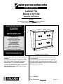 1
1
-
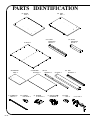 2
2
-
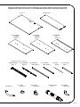 3
3
-
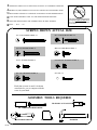 4
4
-
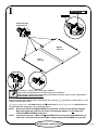 5
5
-
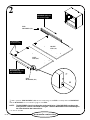 6
6
-
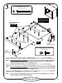 7
7
-
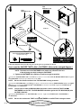 8
8
-
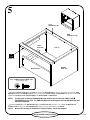 9
9
-
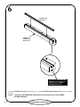 10
10
-
 11
11
-
 12
12
-
 13
13
-
 14
14
-
 15
15
-
 16
16
-
 17
17
-
 18
18
-
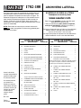 19
19
-
 20
20
-
 21
21
-
 22
22
-
 23
23
-
 24
24
-
 25
25
-
 26
26
-
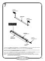 27
27
-
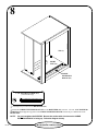 28
28
-
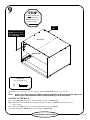 29
29
-
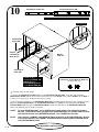 30
30
-
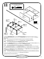 31
31
-
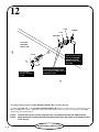 32
32
-
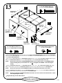 33
33
-
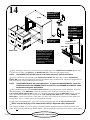 34
34
-
 35
35
-
 36
36


en otros idiomas
- français: Sauder 101702 Manuel utilisateur
- English: Sauder 101702 User manual
Artículos relacionados
-
Sauder 101785 Assembly Instructions Manual
-
-
-
-
-
-
-
-
-