Sauder 409064 Assembly Instructions Manual
- Tipo
- Assembly Instructions Manual

04 / 26 / 13
Lot #: 352741
Date Purchased:
409064
Assembly Instructions
Instructions d’assemblage
Instrucciones de Ensamblaje
DO NOT RETURN YOUR UNIT TO THE STORE
Contact us first
NE PAS RAPPORTER L’ÉLÉMENT AU MAGASIN
Nous contacter en premier
NO DEVUELVA SU UNIDAD A LA TIENDA
Comuníquese con nosotros primero
This instruction booklet contains important safety information.
Please read and keep for future reference.
NOTE
Este folleto de instrucciones contiene información importante sobre la seguridad.
Por favor lea y guárdelo para referencia en el futuro.
NOTA
Ce manuel d’instructions contient d’importantes informations relatives à la sécurité.
À lire et conserver pour toute référence future.
REMARQUE
www.sauder.com
For immediate service, our website is available
24 hours a day, 7 days a week
to order replacement parts, access assembly tips,
register your product, and view Sauder products.
Most replacement parts ship from our
facility in one or two business days.
Les pièces de rechange sont, pour la plupart, expédiées de
notre établissement dans les un à deux jours ouvrables.
La mayoría de piezas de repuesto son enviadas desde
nuestra instalación en uno o dos días laborables.
Mon-Fri -- 9am-5:30pm ET
United States and Canada (except holidays)
Consumer Services 1--800--523--3987
register your new purchase online
www.sauder.com
Mobile Lifestyle Center
Meuble mobile Lifestyle
Mueble móvil Lifestyle
Pour obtenir une service immédiate, notre site Internet
est disponible 24 heures sur 24, 7 jours sur 7,
pour commander des pièces de rechange,
des conseils d’assemblage, enregistrer tout produit
ou visualiser des produits Sauder.
Du lundi au vendredi de9h00à17h30
(heure normale de l’est)
Aux États--Unis et au Canada (sauf jours fériés)
Services aux consommateurs 1--800--523--3987
Para el servicio inmediata, nuestro sitio Web está
disponible las 24 horas al día,
7 días a la semana para pedir piezas de repuesto,
consejos de ensamblaje, registrar su producto y
ver los productos Sauder.
De lunes a viernes de 9 a.m. a 5:30 p.m. (hora del este)
Estados Unidos y Canadá (salvo días festivos)
Servicios del consumidor 1--800--523--3987
The Edge Water Collection
La Collection Edge Water
La Colección Edge Water

PARTS IDENTIFICATION: Each part for this unit may not have a label or inked letter on it. Use this PARTS
IDENTIFICATION page, the labels, and the inked letters to help distinguish similar parts from each other.
IDENTIFICATION DES PIÈCES : Les pièces de cet élément ne comportent peut--être pas toutes une
étiquette ou une lettre imprimée. Utiliser cette page IDENTIFICATION DES PIÈCES, les étiquettes et les lettres
imprimées pour faciliter l’identification des pièces semblables.
IDENTIFICACIÓN DE LAS PARTES: Cada pieza para esta unidad puede que no tenga una etiqueta o una
letra entintada. Use esta página IDENTIFICACIÓN DE LAS PARTES, etiquetas y las letras entintadas para ayudar
a identificar piezas similares.
409064
UPRIGHT -- 1
MONTANT -- 1
PARAL -- 1
RIGHT END -- 1
EXTRÉMITÉ DROITE -- 1
EXTREMO DERECHO -- 1
LEFT END -- 1
EXTRÉMITÉ GAUCHE -- 1
EXTREMO IZQUIERDO -- 1
A B C
BOTTOM -- 1
DESSOUS -- 1
FONDO -- 1
TOP -- 1
DESSUS -- 1
PANEL SUPERIOR -- 1
SMALL TOP -- 1
PETIT DESSUS -- 1
PANEL SUPERIOR PEQUEÑO -- 1
D E F
PRINTER SHELF -- 1
TABLETTE D’IMPRIMANTE -- 1
ESTANTE DE IMPRESORA -- 1
SMALL BOTTOM -- 1
PETIT DESSOUS -- 1
FONDO PEQUEÑO -- 1
LAPTOP SHELF -- 1
TABLETTE D’ORDINATEUR PORTATIF -- 1
ESTANTE DE COMPUTADOR PORTÁTIL -- 1
G H I
DOOR -- 2
PORTE -- 2
PUERTA -- 2
SMALL BACK -- 1
PETIT ARRIÈRE -- 1
DORSO PEQUEÑO -- 1
BACK -- 1
ARRIÈRE -- 1
DORSO -- 1
J K L

409064
PARTS IDENTIFICATION (CONTINUED):
IDENTIFICATION DES PIÈCES (SUITE) :
IDENTIFICACIÓN DE LAS PARTES (CONTINUACIÓN):
LAPTOP SHELF MOLDING -- 1
MOULURE DE LA TABLETTE D’ORDINATEUR PORTATIF -- 1
MOLDURA DEL ESTANTE DE COMPUTADORA PORTÁTIL -- 1
LEG -- 2
PIED -- 2
PATA -- 2
MOLDING -- 2
MOULURE -- 2
MOLDURA -- 2
M N O
FOOT -- 2
PIED -- 2
PATA -- 2
P
HARDWARE IDENTIFICATION:
IDENTIFICATION DES PIÈCES DE QUINCAILLERIE :
IDENTIFICACIÓN DE HERRAJES:
EXTENSION SLIDE -- 2
COULISSE D’EXTENSION -- 2
CORREDERA DE EXTENSIÓN -- 2
R
EXTENSION RAIL -- 2
GLISSIÈRE D’EXTENSION -- 2
RIEL DE EXTENSIÓN -- 2
Q
TWIST-LOCK
R
FASTENER -- 3
FIXATION TWIST–LOCK
R
-- 3
SUJETADOR TWIST–LOCK
R
-- 3
S
HIDDEN CAM -- 18
EXCENTRIQUE ESCAMOTABLE -- 18
EXCÉNTRICO ESCONDIDO -- 18
1F
CAM SCREW -- 6
VIS D’EXCENTRIQUE -- 6
BIELA DE EXCÉNTRICO -- 6
8F
CAM DOWEL -- 12
CHEVILLE D’EXCENTRIQUE -- 12
PASADOR DE EXCÉNTRICO -- 12
2F
METAL PIN -- 6
GOUPILLE EN MÉTAL -- 6
ESPIGA DE METAL -- 6
X
METAL BRACKET -- 7
CONSOLE EN MÉTAL -- 7
SOPORTEDEMETAL--7
W
(EXTENSION SET SHOWN SEPARATED)
(ENSEMBLE DE EXTENSION ILLUSTRÉ À PART)
(JUEGO DE EXTENSIÓN MOSTRADO SEPARADO)

409064
HARDWARE IDENTIFICATION (CONTINUED):
IDENTIFICATION DES PIÈCES DE QUINCAILLERIE (SUITE) :
IDENTIFICACIÓN DE HERRAJES (CONTINUACIÓN):
RAIL BRACKET -- 4
CONSOLE DE GLISSIÈRE -- 4
MÉNSULA DE RIEL -- 4
Y
HINGE -- 2
CHARNIÈRE -- 2
BISAGRA -- 2
BB
KNOB -- 2
POIGNÉE -- 2
TIRADOR -- 2
Z
BACKPLATE -- 2
FERRURE -- 2
PLACA DE TIRADOR -- 2
AA
DOOR HINGE -- 4
CHARNIÈRE DE PORTE -- 4
BISAGRA DE PUERTA -- 4
CC
CAM COVER -- 2
COUVERCLE D’EXCENTRIQUE -- 2
CUBIERTA DE EXCÉNTRICO -- 2
DD
FELT DISC CARD -- 1
FICHE DE TAMPONS EN FEUTRE - 1
TARJETA CON TOPES DE FIELTRO - 1
EE
WHEEL RUNNER -- 6
COULISSEAU À ROULETTES -- 6
RUEDA DE GIRO LIBRE -- 6
GG
CORD CLIP -- 3
CLIP DE CORDON -- 3
GRAPA DE CABLE -- 3
FF
LAPTOP PAD -- 1
TAPIS POUR ORDINATEUR PORTABLE -- 1
ALMOHADILLA PARA COMPUTADORA PORTÁTIL -- 1
HH
Certificate of Conformity
1. This certificate applies to the Sauder
Woodworking Product identified by this
Instruction Book.
2. This certificate applies to compliance of this
product with the CPSC Ban on
Lead--Containing Paint (16 CFR 1303).
3. This product is manufactured by:
Sauder Woodworking Company
502 Middle Street
Archbold, Ohio 43502
(419) 446--2711
4. Date of Manufacture: ________________

409064
BLACK 1--7/8” FLAT HEAD SCREW -- 2
VIS NOIRE TÊTE PLATE 48 mm -- 2
TORNILLO NEGRO DE CABEZA PERDIDA de 48 mm -- 2
BLACK 1--5/8” PAN HEAD SCREW -- 2
VIS NOIRE TÊTE GOUTTE DE SUIF 41 mm -- 2
TORNILLO NEGRO DE CABEZA REDONDA de 41 mm -- 2
1
NOTE / REMARQUE / NOTA:
Using a SCREW that is too long will cause damage. Before beginning assembly, separate
each type of SCREW. Carefully study the SCREW diagrams below (SHOWN ACTUAL SIZE
).
Pay close attention to the color of each SCREW. You may receive extra hardware with your unit.
L’usage d’une VIS trop longue peut endommager l’élément. Avant de commencer l’assemblage, séparer chaque
type de VIS. Attentivement, réviser les schémas des VIS ci--dessous (VIS ILLUSTRÉES GRANDEUR NATURE
).
Faire attention à la couleur de chaque VIS. Il est possible que unes pièces supplémentaires sont incluses avec l’élément.
El uso de un TORNILLO demasiado largo causará daño. Antes de comenzar el ensamblaje, separe cada tipo de TORNILLO.
Atentamente estudie los diagramas de TORNILLO abajo (TORNILLOS MOSTRADOS EN TAMAÑO REAL
).
Preste cuidadosa atención al color de cada TORNILLO. Es posible que se incluyen unas piezas de herraje suplementarias
con la unidad.
II JJ
MM NN
OO PP
BLACK 1--1/8” MACHINE SCREW -- 2
VIS NOIRE À MÉTAUX 28 mm -- 2
TORNILLO NEGRO PARA METAL de 28 mm -- 2
BLACK 7/8” LARGE HEAD SCREW -- 4
VIS NOIRE TÊTE LARGE 22 mm -- 4
TORNILLO NEGRO DE CABEZA GRANDE de 22 mm -- 4
KK LL
BLACK 9/16” LARGE HEAD SCREW -- 30
VIS NOIRE TÊTE LARGE 14 mm -- 30
TORNILLO NEGRO DE CABEZA GRANDE de 14 mm -- 30
BLACK 1/2” FLAT HEAD SCREW -- 8
VIS NOIRE TÊTE PLATE 13 mm -- 8
TORNILLO NEGRO DE CABEZA PERDIDA de 13 mm -- 8
GOLD 5/16” FLAT HEAD SCREW -- 4
VIS DORÉE TÊTE PLATE 8 mm -- 4
TORNILLO DORADO DE CABEZA PERDIDA de 8 mm -- 4
NAIL -- 26
CLOU -- 26
CLAVO -- 26
ASSEMBLY TOOLS REQUIRED
OUTILS D’ASSEMBLAGE REQUIS
HERRAMIENTAS DE ENSAMBLAJE REQUERIDAS
TIP SHOWN ACTUAL SIZE
POINTE GRANDEUR NATURE
PUNTA MOSTRADA EN TAMAÑO REAL
HAMMER
MARTEAU
MARTILLO
NO. 2 PHILLIPS SCREWDRIVER
TOURNEVIS À TÊTE CRUCIFORME PHILLIPS n_2
DESTORNILLADOR PHILLIPS (CRUZ) No. 2

2
409064
H
www.sauder. com/services
S
Assembler l’élément sur un sol à
moquette ou sur le carton vide pour éviter
d’endommager l’élément ou le sol.
- Pour commencer l’assemblage,
enfoncer une FIXATION
TWIST--LOCK
R
SAUDER (S) dans les
gros trous dans la TABLETTE
D’ORDINATEUR PORTATIF (H).
REMARQUE
: Ne pas serrer les
FIXATIONS TWIST--LOCK
R
àcestade
de l’assemblage.
Assemble your unit on a carpeted
floor or on the empty carton to
avoid scratching your unit or
the floor.
- To begin assembly, push a
SAUDER TWIST-LOCK
R
FASTENER (S) into the large holes
in the LAPTOP SHELF (H).
NOTE
: Do not tighten the
TWIST-LOCK
R
FASTENERS at
this time.
Ensamble la unidad sobre un piso
alfombrado o sobre el cartón vacío para
evitar rayar la unidad o el piso.
- Para comenzar el ensamblaje, empuje
un SUJETADOR TWIST--LOCK
R
SAUDER (S) dentro de los agujeros
grandes del ESTANTE DE
COMPUTADOR PORTÁTIL (H).
NOTA
: No apriete los SUJETADORES
TWIST--LOCK
R
por ahora
Look for this icon. It means a video assembly tip is available at:
Repérer cette icône. Elle signifie qu’un conseil de montage vidéo est disponible à :
Busque este icono. Significa que un consejo práctico para ensamble de muebles, grabado en video, está disponible en:
www.sauder.com/services/tips

3
409064
www.sauder. com/services
(12 used)
(12 utilisées)
(12 utilizados)
Do not tighten the HIDDEN CAMS in this step.
Ne pas
serrer les EXCENTRIQUES ESCAMOTABLES à cette étape.
No
apriete los EXCÉNTRICOS ESCONDIDOS en este paso.
Insert the CAM DOWEL into the HIDDEN CAM.
Insérer la CHEVILLE D’EXCENTRIQUE dans
l’EXCENTRIQUE ESCAMOTABLE.
Inserte el PASADOR DE EXCÉNTRICO dentro
del EXCÉNTRICO ESCONDIDO.
Arrow
Flèche
Flecha
Arrow
Flèche
Flecha
- Enfoncer dix--huit EXCENTRIQUES
ESCAMOTABLES (1F) dans les
EXTRÉMITÉS (A et B), le
DESSOUS (F), le PETIT DESSOUS (G)
et le PETIT ARRIÈRE (J). Insérer ensuite
l’extrémité en métal d’une CHEVILLE
D’EXCENTRIQUE (2F) dans chaque
EXCENTRIQUE ESCAMOTABLE, à
l’exception des EXCENTRIQUES de le
chant long des EXTRÉMITÉS.
- Push eighteen HIDDEN
CAMS (1F) into the ENDS (A
and B), BOTTOM (F), SMALL
BOTTOM (G) and SMALL
BACK (J). Then, insert the metal
end of a CAM DOWEL (2F) into
each HIDDEN CAM, except for
the CAMS in the long edge of the
ENDS.
- Empuje dieciocho EXCÉNTRICOS
ESCONDIDOS (1F) dentro de los
EXTREMOS (A y B), del FONDO (F),
del FONDO PEQUEÑO (G) y del
DORSO PEQUEÑO (J). A continuación,
inserte el extremo en metal de un
PASADOR DE EXCÉNTRICO (2F)
dentro de cada EXCÉNTRICO
ESCONDIDO, menos en el borde largo de
los EXTREMOS.
Arrow
Flèche
Flecha
(18 used)
(18 utilisées)
(18 utilizados)
Do not insert CAM DOWELS (U)
into these edges.
Ne pas insérer les CHEVILLES
D’EXCENTRIQUE (U) dans ces
chants.
No inserte los PASADORES DE
EXCÉNTRICO (U) dentro de
estos bordes.
A
B
F
G
J
2F
1F
1F
2F

4
409064
www.sauder. com/services
- Turn six CAM SCREWS (8F)
into the LEGS (M).
- Atornille seis BIELAS DE
EXCÉNTRICO (8F) dentro de las
PATAS (M).
- Faire tourner six VIS
D’EXCENTRIQUE (8F) dans les
PIEDS (M).
M
M
8F

5
409064
www.sauder. com/services
GG
- With a hammer, gently tap six
WHEEL RUNNERS (GG) into the
ENDS (A and B).
NOTE
: Measure the height of your
printer. You have the choice of
mounting the RAIL BRACKETS
in three different height positions to
fit your printer. The three positions
will allow a clearance of 11”,
13 1/2” and 15”.
- Fasten four RAIL
BRACKETS (Y) to the ENDS (A
and B). Use eight BLACK 9/16”
LARGE HEAD SCREWS (MM).
- Con un martillo, suavemente con
pequeños golpes introduzca seis
RUEDAS DE GIRO LIBRE (GG) en los
EXTREMOS (A y B).
NOTA
: Mida la altura a su impresora.
Usted tiene la opción de montar los
SOPORTES DE RIEL en tres diferentes
posiciones de altura para fijar su
impresora. Las tres posiciones permitirán
una separación de 30 cm, 34 cm y 38 cm.
- Fije cuatro MÉNSULAS DE RIEL (Y)
a los EXTREMOS (A y B). Utilice ocho
TORNILLOS NEGROS DE CABEZA
GRANDE de 14 mm (MM).
- À l’aide d’un marteau, enfoncer
délicatement six COULISSEAUX À
ROULETTES (GG) dans les
EXTRÉMITÉS (A et B).
REMARQUE
: Mesurer la longueur de
l’imprimante. Les CONSOLES DE
GLISSIÈRES peuvent être montées à trois
hauteurs différentes pour convenir à
l’imprimante. Ces trois positions offriront
un dégagement de 30 cm, 34 cm et 38 cm.
- Fixer quatre CONSOLES DE
GLISSIÈRE (Y) aux EXTRÉMITÉS (A
et B). Utiliser huit VIS NOIRES TÊTE
LARGE 14 mm (MM).
Y
8usedinthisstep
8 utilisées à cette étape
8 utilizados en este paso
Black
Noire
Negro
MM
A
B
Use these holes for 15” printer clearance.
Utiliser ces trous pour avoir un
dégagement d’imprimante de 38 cm.
Utilice estos agujeros para la separación
de 38 cm de la impresora.

6
409064
www.sauder. com/services
- Separate the EXTENSION
SLIDES (R) from the EXTENSION
RAILS (Q) as shown in the upper
diagram. Be prepared, the parts are
greasy.
- Fasten an EXTENSION
RAIL (Q) to the RAIL BRACKETS
on each END (A and B). Use four
GOLD 5/16” FLAT HEAD
SCREWS (OO).
NOTE
: For each EXTENSION
RAIL, turn a SCREW into the hole
shown in the enlarged diagram.
Then, slide the inner cartridge of the
EXTENSION RAIL out to find the
other hole that lines up with the hole
in the END. Turn a SCREW into this
hole.
- Separe las CORREDERAS DE
EXTENSIÓN (R) de los RIELES DE
EXTENSIÓN (Q) como se muestra en el
diagrama superior. Prepárese, las piezas
son grasientas.
- Fije un RIEL DE EXTENSIÓN (Q) a
las MÉNSULAS DE RIEL en cada
EXTREMO (A y B). Utilice cuatro
TORNILLOS DORADOS DE CABEZA
PERDIDA de 8 mm (OO).
NOTA
: Para cada RIEL DE
EXTENSIÓN, atornille un TORNILLO
dentro del agujero indicado en el
diagrama ampliado. A continuación
deslice el cartucho interno del RIEL DE
EXTENSIÓN hacia el exterior para
encontrar el otro agujero que se alinea con
el agujero del EXTREMO. Atornille un
TORNILLO dentro de este agujero.
- Séparer les COULISSES
D’EXTENSION (R) des GLISSIÈRES
D’EXTENSION (Q) comme l’indique le
schéma du haut. Faire attention car les
pièces sont graissées.
- Fixer une GLISSIÈRE
D’EXTENSION (Q) aux CONSOLES DE
GLISSIÈRE de chaque EXTRÉMITÉ (A
et B). Utiliser quatre VIS DORÉES TÊTE
PLATE 8 mm (OO).
REMARQUE
: Pour chaque GLISSIÈRE
D’EXTENSION, faire tourner une VIS
dans le trou indiqué dans le schéma
agrandi. Ensuite, enfiler la cartouche
internedelaGLISSIÈRE
D’EXTENSION vers l’extérieur pour
trouver l’autre trou qui est aligné sur le
trou dans l’EXTRÉMITÉ. Faire tourner
une VIS dans ce trou.
Push the black lever in and pull the SLIDE from the RAIL.
Appuyer le levier noir vers l’intérieur et tirer la COULISSE de la GLISSIÈRE.
Empuje la palanca negra hacia el interior y separe la CORREDERA del RIEL.
QR
Hole
Trou
Agujero
Open end
Extrémité ouverte
Extremo abierto
Open end
Extrémité ouverte
Extremo abierto
4usedinthisstep
4 utilisées à cette étape
4 utilizados en este paso
Gold
Dorée
Dorado
OO
A
B
Edge with HIDDEN CAMS
Chant avec les EXCENTRIQUES ESCAMOTABLES
Borde con EXCÉNTRICOS ESCONDIDOS
Edge with HIDDEN CAMS
Chant avec les EXCENTRIQUES ESCAMOTABLES
Borde con EXCÉNTRICOS ESCONDIDOS
Q
Q

7
409064
www.sauder. com/services
- Fasten the LEGS (M) to the
ENDS (A and B). Tighten six
HIDDEN CAMS.
- Fasten the FEET (P) to the
LEGS (M). Use two BLACK
1--5/8PANHEADSCREWS(JJ).
- Fije las PATAS (M) a los
EXTREMOS (A y B). Apriete seis
EXCÉNTRICOS ESCONDIDOS.
- Fije las PATAS (P) a las PATAS (M).
Utilice dos TORNILLOS NEGROS DE
CABEZA REDONDA de 41 mm (JJ).
- Fixer les PIEDS (M) aux
EXTRÉMITÉS (A et B). Serrer six
EXCENTRIQUES ESCAMOTABLES.
- Fixer les PIEDS (P) aux PIEDS (M).
Utiliser deux VIS NOIRES TÊTE
GOUTTE DE SUIF 41 mm (JJ).
M
M
A
B
2usedinthisstep
2 utilisées à cette étape
2 utilizados en este paso
Black
Noire
Negro
JJ
P
P
These surfaces should be even.
Ces surfaces devraient être à fleur.
Estas superficies deben estar niveladas.
1
2

8
409064
www.sauder. com/services
The unfinished area is closer to the top
surface.
La surface non finie se trouve plus près de
la surface supérieure.
El área sin acabado está más cerca a la
superficie superior.
How to use the SAUDER
TWIST-LOCK
R
FASTENER (Refer to the
enlarged
diagram.)
1. Insert the dowel end of the
FASTENER into the hole of the
adjoining part.
NOTE
: The dowel end of the
FASTENER must remain fully inserted
in the hole of the adjoining part while
locking the FASTENER.
2. Tighten the FASTENER with a
Phillips screwdriver as tight as possible.
- Fasten the LAPTOP SHELF
MOLDING (O) to the LAPTOP
SHELF (H). Tighten three
TWIST-LOCK
R
FASTENERS.
Cómo utilizar el SUJETADOR
TWIST--LOCK
R SAUDER
(Refiérase al diagrama ampliado.)
1. Inserte el extremo con cabilla del
SUJETADOR dentro del agujero de la
parte adjunta.
NOTA:
El extremo con cabilla del
SUJETADOR debe quedarse
completamente insertado en el agujero de
la parte adjunta cuando se enclava el
SUJETADOR.
2. Apriete el SUJETADOR lo más
apretado posible con un destornillador
Phillips (cruz).
- Fije la MOLDURA DEL ESTANTE
DE COMPUTADORA PORTÁTIL (O) al
ESTANTE DE COMPUTADORA
PORTÁTIL (H). Apriete tres
SUJETADORES TWIST--LOCK
R
.
Utilisation de la FIXATION
TWIST--LOCK
R SAUDER
(Consulter le schéma agrandi.)
1. Insérer l’extrémité filetée de la
FIXATION dans le trou de la pièce
attenante.
REMARQUE
: L’extrémité filetée de
la FIXATION doit rester complètement
inséréedansletroudelapièce
attenante lorsque l’on bloque la
FIXATION.
2. Bien serrer la FIXATION à l’aide
d’un tournevis Phillips.
- Fixer la MOULURE DE
TABLETTE POUR ORDINATEUR
PORTABLE (O) sur la TABLETTE
POUR ORDINATEUR
PORTABLE (H). Serrer trois
FIXATIONS TWIST--LOCK
R
.
H
O
Surface with TWIST-LOCK
R
FASTENERS
Surface avec les FIXATIONS TWIST--LOCKR
Superficie con SUJETADORES TWIST--LOCKR

9
www.sauder. com/services
2usedinthisstep
2 utilisées à cette étape
2 utilizados en este paso
Black
Noire
Negro
II
- Fasten the SMALL
BOTTOM (G) to the
UPRIGHT (C). Tighten two
HIDDEN CAMS.
- Fasten the SMALL BACK (J)
to the SMALL BOTTOM (G). Use
two BLACK 1--7/8” FLAT HEAD
SCREWS (II).
- Fije el FONDO PEQUEÑO (G) al
PARAL (C). Apriete dos EXCÉNTRICOS
ESCONDIDOS.
- Fije el DORSO PEQUEÑO (J) al
FONDO PEQUEÑO (G). Utilice dos
TORNILLOS NEGROS DE CABEZA
PERDIDA de 48 mm (II).
- Fixer le PETIT DESSOUS (G) au
MONTANT (C). Serrer deux
EXCENTRIQUES ESCAMOTABLES.
- Fixer le PETIT ARRIÈRE (J) au
PETIT DESSOUS (G). Utiliser deux VIS
NOIRES TÊTE PLATE 48 mm (II).
G
C
J
Large hole
Grand trou
Agujero grande
Surface with HIDDEN CAMS
Surface avec les EXCENTRIQUES ESCAMOTABLES
Superficie con EXCÉNTRICOS ESCONDIDOS
Caution
Risk of damage or injury. Hidden Cams
must be completely tightened. Hidden
Cams that are not completely tightened
may loosen, and parts may separate.
Turn the hidden cam 210 degrees to
completely tighten it.
Precaución
Riesgo de daños o heridas. Los
Excéntricos Escondidos deben a
pretarse completamente. Los Excéntricos
Escondidos que no se aprieten
completamente se aflojarán y las
partes pueden separarse. Para apretar
completamente, atornille el excéntrico
escondido 210 grados.
Attention
Risque des dégâts ou blessures. Les
Excentriques Escamotables doivent
être serrés à bloc. Les Excentriques
Escamotables que ne sont pas serrées
à par bloc peuvent desserrer et les
piées peuvent séarer. Pour serrer à
bloc, faire tourner l’excentrique
escamotable de 210 degrés.
Arrow
Flèche
Flecha
Arrow
Flèche
Flecha
Maximum 210 degrees
Maximum de 210 degrés
Máximo de 210 grados
Minimum 190 degrees
Minimum de 190 degrés
Mínimo de 190 grados
Tighten
Serrer
Apriete
Start
Commencer
Comience
409064

10
www.sauder. com/services
Unfinished surface
Surface non finie
Superficie sin acabado
C
J
- Insert six METAL PINS (X)
into the short edges of the
UPRIGHT (C) and SMALL
BACK (J).
- Push the CAM DOWEL and
PINS (X) of the SMALL BACK (J)
and UPRIGHT (C) into the holes of
the RIGHT END (A).
NOTE
: Do not tighten the
HIDDEN CAM in the SMALL
BACK at this time.
- Fasten the BOTTOM (F) to the
RIGHT END (A). Tighten two
HIDDEN CAMS.
- Inserte seis ESPIGAS DE METAL (X)
dentro de los bordes cortos del
PARAL (C) y del DORSO
PEQUEÑO (J).
- Empuje el PASADOR DE
EXCÉNTRICO y las ESPIGAS (X) del
DORSO PEQUEÑO (J) y del PARAL (C)
en los agujeros del EXTREMO
DERECHO (A).
NOTA
: No apriete el EXCÉNTRICO
ESCONDIDO en el DORSO PEQUEÑO
en este momento.
- Fije el FONDO (F) al EXTREMO
DERECHO (A). Apriete dos
EXCÉNTRICOS ESCONDIDOS.
- Insérer six GOUPILLES EN
MÉTAL (X) dans les chants courts du
MONTANT (C) et PETIT ARRIÈRE (J).
- Enfoncer la CHEVILLE
D’EXCENTRIQUE et les
GOUPILLES (X) du PETIT ARRIÈRE (J)
et du MONTANT (C) dans les trous de
l’EXTRÉMITÉ DROITE (A).
REMARQUE
: Ne pas serrer
l’EXCENTRIQUE ESCAMOTABLE
dans le PETIT ARRIÈRE à ce point.
- Fixer le DESSOUS (F) à
l’EXTRÉMITÉ DROITE (A). Serrer deux
EXCENTRIQUES ESCAMOTABLES.
X
X
Do not stand the unit upright without the
BACK fastened. The unit may collapse.
No coloque la unidad en posición
vertical hasta que se fije el DORSO.
La unidad podría caerse.
Ne pas relever l’élément dans sa position
verticale avant d’avoir fixé l’ARRIÈRE.
L’élément risque de s’effondrer.
Caution
Attention
Precaución
F
A
Minimum 190 degrees
Minimum 190 degrés
Minimo 190 grados
Arrow
Flèche
Flecha
Maximum 210 degrees
Maximum 210 degrés
Mazximo 210 grados
409064

11
www.sauder. com/services
C
J
F
- Fasten the LEFT END (B) to
the BOTTOM (F). Tighten two
HIDDEN CAMS.
NOTE
: Be sure the METAL PINS
in the UPRIGHT (C) and SMALL
BACK (J) inserts into the holes in
the LEFT END. Do not tighten the
HIDDEN CAM in the SMALL
BACK at this time.
- Fije el EXTREMO IZQUIERDO (B)
al FONDO (F). Apriete dos
EXCÉNTRICOS ESCONDIDOS.
NOTA
: Asegúrese de insertar las
ESPIGAS DE METAL sujetadas al
PARAL (C) y al DORSO PEQUEÑO (J)
dentro de los agujeros del EXTREMO
IZQUIERDO. No apriete el
EXCÉNTRICO ESCONDIDO en el
DORSO PEQUEÑO en este momento.
- Fixer l’EXTRÉMITÉ GAUCHE (B)
au DESSOUS (F). Serrer deux
EXCENTRIQUES ESCAMOTABLES.
REMARQUE
: S’assurer de bien insérer
les GOUPILLES EN MÉTAL situées sur
le MONTANT (C) et PETIT
ARRIÈRE (J) dans les trous dans
l’EXTRÉMITÉ GAUCHE. Ne pas serrer
l’EXCENTRIQUE ESCAMOTABLE
dans le PETIT ARRIÈRE à ce point.
B
Minimum 190 degrees
Minimum 190 degrés
Minimo 190 grados
Arrow
Flèche
Flecha
Maximum 210 degrees
Maximum 210 degrés
Mazximo 210 grados
409064

12
www.sauder. com/services
Unfinished surface
Surface non finie
Superficie sin acabado
Rounded edge
Chant arrondi
Borde redondeado
- Fasten the TOP (D) to the
ENDS (A and B). Tighten four
HIDDEN CAMS.
- Fije el PANEL SUPERIOR (D) a los
EXTREMOS (A y B). Apriete cuatro
EXCÉNTRICOS ESCONDIDOS.
- Fixer le DESSUS (D) aux
EXTRÉMITÉS (A et B). Serrer quatre
EXCENTRIQUES ESCAMOTABLES.
D
A
B
Minimum 190 degrees
Minimum 190 degrés
Minimo 190 grados
Arrow
Flèche
Flecha
Maximum 210 degrees
Maximum 210 degrés
Mazximo 210 grados
409064

13
www.sauder. com/services
- Fixer sept CONSOLES EN
MÉTAL (W) au DESSUS (D) et
DESSOUS (F). Utiliser sept VIS NOIRES
TÊTE LARGE 14 mm (MM).
REMARQUE : S’assurer que les
CONSOLES sont à fleur du chant
supérieur du DESSOUS.
- Fasten seven METAL
BRACKETS (W) to the TOP (D)
and BOTTOM (F). Use seven
BLACK 9/16” LARGE HEAD
SCREWS (MM).
NOTE
: Be sure the BRACKETS
are even with the top edge of the
BOTTOM.
- Fije siete SOPORTES DE
METAL (W) al PANEL SUPERIOR (D) y
al FONDO (F). Utilice siete TORNILLOS
NEGROS DE CABEZA GRANDE de
14 mm (MM).
NOTA: Asegúrese que los SOPORTES
estén nivelados con el borde superior del
FONDO.
W
W
D
F
7usedinthisstep
7 utilisées à cette étape
7 utilizados en este paso
Black
Noire
Negro
MM
409064

14
409064
www.sauder. com/services
- Fixer les MOULURES (N) sur les
CONSOLES EN MÉTAL (W) du
DESSUS et du DESSOUS. Utiliser sept
VIS NOIRES TÊTE LARGE
14 mm (MM).
- Fasten the MOLDINGS (N) to
the METAL BRACKETS (W) on
the TOP and BOTTOM. Use seven
BLACK 9/16” LARGE HEAD
SCREWS (MM).
- Fije las MOLDURAS (N) a los
SOPORTES DE METAL (W) en el
PANEL SUPERIOR y en el FONDO.
Utilice siete TORNILLOS NEGROS DE
CABEZA GRANDE de 14 mm (MM).
D
F
7usedinthisstep
7 utilisées à cette étape
7 utilizados en este paso
Black
Noire
Negro
MM
N
Rounded edge
Chant arrondi
Borde redondeado
N

15
409064
www.sauder. com/services
8usedinthisstep
8 utilisées à cette étape
8 utilizados en este paso
Black
Noire
Negro
MM
- Carefully turn your unit over
onto its front edges.
- Fasten the SMALL BACK (J)
to the ENDS (A and B). Tighten
two HIDDEN CAMS.
- Fasten two HINGES (BB) to the
SMALL BACK (J). Use four
BLACK 9/16” LARGE HEAD
SCREWS (MM).
- Fasten the SMALL TOP (E) to
the HINGES. Use four BLACK
9/16” LARGE HEAD
SCREWS (MM).
- Cuidadosamente voltee la unidad para
que repose sobre los bordes delanteros.
- Fije el DORSO PEQUEÑO (J) a los
EXTREMOS (A y B). Apriete dos
EXCÉNTRICOS ESCONDIDOS.
- Fije dos BISAGRAS (BB) al DORSO
PEQUEÑO (J). Utilice cuatro
TORNILLOS NEGROS DE CABEZA
GRANDE de 14 mm (MM).
- Fije el PANEL SUPERIOR
PEQUEÑO (E) a las BISAGRAS. Utilice
cuatro TORNILLOS NEGROS DE
CABEZA GRANDE de 14 mm (MM).
- Avec précaution, retourner
l’élément sur ses chants avant.
- Fixer le PETIT ARRIÈRE (J) aux
EXTRÉMITÉS (A et B). Serrer deux
EXCENTRIQUES ESCAMOTABLES.
- Fixer deux CHARNIÈRES (BB) sur le
PETIT ARRIÈRE (J). Utiliser quatre VIS
NOIRES TÊTE LARGE 14 mm (MM).
- Fixer le PETIT DESSUS (E) aux
CHARNIÈRES. Utiliser quatre VIS
NOIRES TÊTE LARGE 14 mm (MM).
B
A
E
BB
J
Tighten these HIDDEN CAMS.
Serrer ces EXCENTRIQUES ESCAMOTABLES.
Apriete estos EXCÉNTRICOS ESCONDIDOS.
Minimum 190 degrees
Minimum 190 degrés
Minimo 190 grados
Arrow
Flèche
Flecha
Maximum 210 degrees
Maximum 210 degrés
Mazximo 210 grados

16
409064
www.sauder. com/services
Do not stand the unit upright without the
BACK fastened. The unit may collapse.
No coloque la unidad en posición
vertical hasta que se fije el DORSO.
La unidad podría caerse.
Ne pas relever l’élément dans sa position
verticale avant d’avoir fixé l’ARRIÈRE.
L’élément risque de s’effondrer.
Caution
Attention
Precaución
- Unfold the BACK (K) and lay it
over your unit.
- Make equal margins along the
bottom and side edges of the
BACK (K). Push on opposite
corners of your unit if needed to
make it “square”.
- Fasten the BACK (K) to your
unit using the NAILS (PP).
NOTE
: Perforations have been
provided for access through the
BACK. Carefully cut out the holes
needed.
- Desdoble el DORSO (K) y colóquelo
sobre la unidad.
- Los márgenes a lo largo de los bordes
laterales e inferior del DORSO (K) debe
estar uniforme. Empuje sobre las
esquinas opuestas de la unidad si es
requerido para hacerla “cuadrada.”
- Fije el DORSO (K) a la unidad
utilizando los CLAVOS (PP).
NOTA
: Hay perforaciones provistas para
el acceso a través del DORSO.
Cuidadosamente corte los agujeros
requeridos.
- Déplier l’ARRIÈRE (K) et le placer
sur l’élément.
- Veiller à avoir des marges égales le
long du chant inférieur et des chants
latéraux de l’ARRIÈRE (K). Si besoin
est, enfoncer sur les coins opposés de
l’élément pour s’assurer d’être «
d’équerre ».
- Fixer l’ARRIÈRE (K) à l’élément en
utilisant les CLOUS (PP).
REMARQUE
: Des lignes perforées ont
été prévues pour accéder facilement à
l’ARRIÈRE. Découper avec précaution
les trous nécessaires.
K
26 used in this step
26 utilisés à cette étape
26 utilizados en este paso
PP

17
409064
www.sauder. com/services
Open end
Extrémité ouverte
Extremo abierto
Open end
Extrémité ouverte
Extremo abierto
4usedinthisstep
4 utilisées à cette étape
4 utilizados en este paso
Black
Noire
Negro
LL
Finished surface
Surface finie
Superficie con acabado
- Fasten the EXTENSION
SLIDES (R) to the PRINTER
SHELF (I). Use four BLACK 7/8”
LARGE HEAD SCREWS (LL).
- Carefully stand your unit
upright.
- To insert the PRINTER SHELF
into your unit, line up the
EXTENSION SLIDES on the
PRINTER SHELF with the
EXTENSION RAILS on the unit
and push the PRINTER SHELF
into the unit until it is fully
inserted. The PRINTER SHELF
will push in hard until it is all the
way in, then it will slide in and out
easier.
- Fije las CORREDERAS DE
EXTENSIÓN (R) al ESTANTE DE
IMPRESORA (I). Utilice cuatro
TORNILLOS NEGROS DE CABEZA
GRANDE de 22 mm (LL).
- Cuidadosamente ponga la unidad en
posición vertical.
- Para insertar el ESTANTE DE
IMPRESORA dentro de la unidad, alinee
las CORREDERAS DE EXTENSIÓN
sujetadas al ESTANTE DE IMPRESORA
con los RIELES DE EXTENSIÓN
sujetados a la unidad y empuje el
ESTANTE DE IMPRESORA dentro de la
unidad hasta que est completamente
insertado. El ESTANTE DE
IMPRESORA se mueve con dificultad
hasta que se inserte completamente dentro
de la unidad. después deslizar fácilmente
hacia adentro y hacia afuera.
- Fixer les COULISSES
D’EXTENSION (R) sur la TABLETTE
POUR IMPRIMANTE (I). Utiliser quatre
VIS NOIRES TÊTE LARGE
22 mm (LL).
- Relever, avec précaution, l’élément
dans sa position verticale.
- Pour insérer la TABLETTE POUR
IMPRIMANTE dans l’élément, aligner
les COULISSES D’EXTENSION de la
TABLETTE POUR IMPRIMANTE sur
les GLISSIÈRES D’EXTENSION de
l’élément et enfoncer la TABLETTE
POUR IMPRIMANTE dans l’élément
jusqu’à ce que la tablette soit
complètement inséré. La TABLETTE
POUR IMPRIMANTE offrira une
certaine résistance jusqu’à ce qu’il soit
complètement inséré dans l’élément, il
glissera ensuite sans difficulté.
R
R
I
I

18
409064
www.sauder. com/services
CC
CC
- Fasten two DOOR HINGES (CC)
to each DOOR (L). Use eight
BLACK 1/2” FLAT HEAD
SCREWS (NN).
- Fije dos BISAGRAS DE
PUERTA (CC) a cada PUERTA (L).
Utilice ocho TORNILLOS NEGROS DE
CABEZA PERDIDA de 13 mm (NN).
- Fixer deux CHARNIÈRES (CC) à
chaque PORTE (L). Utiliser huit VIS
NOIRES TÊTE PLATE 13 mm (NN).
8usedinthisstep
8 utilisées à cette étape
8 utilizados en este paso
Black
Noire
Negro
NN
L
L

19
409064
www.sauder. com/services
AA
Z
2usedinthisstep
2 utilisées à cette étape
2 utilizados en este paso
Black
Noire
Negro
KK
- Fixer une PORTE (L) à
l’EXTRÉMITÉ GAUCHE (B). Utiliser
les vis fournies avec les CHARNIÈRES
DE PORTE (CC). Voir l’étape suivante
pour régler les charnières.
- Fixer une FERRURE (AA) et une
POIGNÉE (Z) sur le devant de la
PORTE (L). Utiliser une VIS NOIRE À
MÉTAUX 28 mm (KK).
- Répéter cette étape pour l’autre
PORTE (L).
- DécollerleTAMPONENFEUTREde
la FICHE DE TAMPONS EN
FEUTRE (EE). Coller un TAMPON EN
FEUTRE sur la TABLETTE POUR
IMPRIMANTE (I) et les
EXTRÉMITÉS (A et B) comme l’indique
le schéma.
- Fasten a DOOR (L) to the
LEFT END (B). Use the screws in
the DOOR HINGES (CC). See the
next step for hinge adjustments.
- Fasten a BACKPLATE (AA)
and KNOB (Z) to the front of the
DOOR (L). Use a BLACK 1--1/8”
MACHINE SCREW (KK).
- Repeat this step for the other
DOOR (L).
- Peel the FELT DISCS from the
FELT DISC CARD (EE). Stick a
FELT DISC on the PRINTER
SHELF (I) and ENDS (A and B) as
shown.
- Fije la PUERTA (L) al EXTREMO
IZQUIERDO (B). Utilice los tornillos
provistos de las BISAGRAS DE
PUERTA (CC). Vea el próximo paso para
los ajustes de bisagras.
- Fije la PLACA DE TIRADOR (AA) y
un TIRADOR (Z) al frente de la
PUERTA (L). Utilice un TORNILLO
NEGRO PARA METAL de 28 mm (KK).
- Repita este paso para la otra
PUERTA (L).
- Separe los TOPES DE FIELTRO de la
TARJETA CON TOPES DE
FIELTRO (EE). Aplique un TOPE DE
FIELTRO en el ESTANTE DE
IMPRESORA (I) y en los
EXTREMOS (A y B) como se muestra.
L
EE
EE
B
A
I

Refer to the enlarged diagram to
identify the parts on the HINGES
and HINGE BRACKETS.
- The DOORS may need some
adjustments. Follow the text below
to make needed adjustments.
DOOR ADJUSTMENTS:
To adjust the DOORS from side to
side (horizontal), loosen the
mounting screw several turns, then
turn the adjusting screw in or out.
Tighten the mounting screw after
making adjustments.
To adjust the DOORS up and down
(vertical), loosen both screws that
fasten the HINGE BRACKETS to
the END. Move the DOORS up or
down to the desired location.
Tighten the screws after making
adjustments.
To adjust the DOORS in or out
(depth), loosen the mounting screw
one turn and move the DOORS in
or out, as needed. Tighten the
mounting screw after making
adjustments.
20
409064
www.sauder. com/services
Consulte el diagrama ampliado para
identificar las piezas de las BISAGRAS y
las MÉNSULAS DE BISAGRA.
- Las PUERTAS pueden requerir de
ajustes. Siga las instrucciones abajo para
hacer los ajustes.
AJUSTE LAS PUERTAS:
Para ajustar las PUERTAS de un lado al
otro (horizontalmente), afloje el tornillo
de montaje varias vueltas y gire el tornillo
de ajuste hacia el interior o hacia el
exterior. Apriete el tornillo de montaje
después de hacer los ajustes.
Para ajustar las PUERTAS hacia arriba o
hacia abajo (vertical), afloje los dos
tornillos que aseguran las MÉNSULAS
DE BISAGRA al EXTREMO. Mueva las
PUERTAS hacia arriba o hacia abajo a la
ubicación deseada. Apriete los tornillos
después de hacer los ajustes.
Para ajustar las PUERTAS hacia atrás o
hacia adelante (profundidad), afloje el
tornillo de montaje una vuelta y mueva las
PUERTAS hacia el interior o hacia el
exterior según sea necesario. Apriete el
tornillo de montaje después de hacer los
ajustes.
Consulter le schéma agrandi pour
identifier les pièces des CHARNIÈRES et
CONSOLES DE CHARNIÈRE.
- Il faut peut--être ajuster les PORTES.
Suivre les indications ci--dessous
pour ajuster.
RÉGLAGES DE PORTES:
Pour ajuster les PORTES latéralement
(horizontalement), desserrer la vis de
montage quelques tours et tourner la vis
de réglage vers l’intérieur ou vers
l’extérieur. Serrer la vis de montage après
avoir ajusté.
Pour ajuster les PORTES de haut en bas
(verticalement), desserrer les deux vis qui
maintiennent les CONSOLES DE
CHARNIÈRE à l’EXTRÉMITÉ. Déplacer
les PORTES verticalement à
l’emplacement désiré. Serrer les vis après
avoir ajusté.
Pour ajuster les PORTES vers l’intérieur
où vers l’extérieur (profondeur), desserrer
la vis de montage un tour et déplacer les
PORTES vers l’intérieur ou vers
l’extérieur. Serrer la vis de montage après
avoir ajusté.
Adjusting screw (horizontal)
Vis de réglage (horizontal)
Tornillo de ajuste (horizontal)
Mounting screw (depth)
Vis de montage (profondeur)
Tornillo de montaje (profundidad)
(vertical adjustment)
(réglage verticale)
(ajuste vertical)

21
409064
www.sauder. com/services
- Commencer par déposer le TAPIS
POUR ORDINATEUR PORTABLE (HH)
de sorte que le Velcro attaché au tapis soit
dirigé vers le haut.
- Ensuite, décoller le papier du côté
adhésif.
- Enfin, retourner le tapis et l’appuyer
fermement sur le centre de la TABLETTE
POUR ORDINATEUR PORTABLE (H).
- First, lay the LAPTOP PAD (HH)
so the velcro attached to the pad is
facing up.
- Next, peel off the paper from
the adhesive side.
- Finally, flip the pad over and
press it firmly onto the center of
the LAPTOP SHELF (H).
- Primero, coloque la ALMOHADILLA
DE COMPUTAORA PORTÁTIL (HH) de
manera que el Velcro fijado a la
almohadilla quede mirando hacia arriba.
- Luego, desprenda el papel del lado
adhesivo.
- Finalmente, coloque la almohadilla
encima y presione firmemente sobre el
centro del ESTANTE DE
COMPUTADORA PORTÁTIL (H).
1. With the velcro centered, peel off the paper so the adhesive side is facing up.
2. Carefully flip the pad over and press it firmly onto the LAPTOP SHELF.
1. Une fois le Velcro centré, décoller le papier de manière à ce que le côté
adhésif soit dirigé vers le haut.
2. Retourner soigneusement le tapis et l’appuyer fermement sur la TABLETTE
POUR ORDINATEUR PORTABLE.
1. Con el Velcro centrado, desprenda el papel de manera que el lado adhesivo
quede dirigido hacia arriba.
2. Cuidadosamente coloque la almohadilla encima y presione firmemente sobre
el ESTANTE DE COMPUTADORA PORTÁTIL.
Surface with TWIST-LOCK
R
FASTENERS
Surface avec les FIXATIONS TWIST--LOCKR
Superficie con SUJETADORES TWIST--LOCKR
H
HH

22
409064
- Poser la TABLETTE POUR
ORDINATEUR PORTABLE (H) sur les
COULISSEAUX À ROULETTES.
- Enfoncer un COUVERCLE
D’EXCENTRIQUE (DD) sur chaque
EXCENTRIQUE ESCAMOTABLE.
- Faire tourner les CLIPS POUR
CORDONS (FF) dans le PETIT
ARRIÈRE (J).
REMARQUE
: Les CLIPS POUR
CORDONS servent à gérer les cordons.
REMARQUE
: Prière de lire
attentivement les importantes
informations concernant la sécurité qui
figurent sur les pages arrière du manuel
d’instructions.
Ceci complète l’assemblage. Pour
nettoyer, utiliser l’encaustique pour
meubles préférée ou un chiffon humide.
Essuyer.
- Set the LAPTOP SHELF (H)
onto the WHEEL RUNNERS.
- Push a CAM COVER (DD)
onto each HIDDEN CAM.
- Turn the CORD CLIPS (FF)
into the SMALL BACK (J).
NOTE
: The CORD CLIPS are
used to manage your cords.
NOTE
: Please read the back pages
of the instruction booklet for
important safety information.
This completes assembly. Clean
with your favorite furniture polish
or a damp cloth. Wipe dry.
- Coloque el ESTANTE PARA LA
COMPUTADORA PORTÁTIL (H) sobre
las RUEDAS DE GIRO LIBRE.
- Empuje una CUBIERTA DE
EXCÉNTRICO (DD) sobre cada
EXCÉNTRICO ESCONDIDO.
- Atornille las GRAPAS DE
CABLE (FF) dentro del DORSO
PEQUEÑO (J).
NOTA
: Las GRAPAS DE CABLE se
utilizan para dirigir sus cables.
NOTA
: Por favor lea las páginas finales
del folleto de instrucciones para
información importante sobre la
seguridad.
Esto completa el ensamblaje. Limpie con
su pulimento para muebles preferido o un
paño húmedo. Seque con un paño.
www.sauder. com/services
50 lbs.
22 kg
20 lbs.
9kg
40 lbs.
18 kg
50 lbs.
22 kg
10 lbs.
4kg
FF
H
J
To cover HIDDEN CAMS
Pour couvrir les EXCENTRIQUES ESCAMOTABLES
Para cubrir los EXCÉNTRICOS ESCONDIDOS
DD
Removable
Laptop Shelf

GARANTÍA LIMITADA DE 5 AÑOS
1. Sauder Woodworking Co. (Sauder
R
) offre une couverture de garantie limitée à
l’acheteur initial du présent produit pendant une période de cinq ans à compter de la
date d’achat contre tout défaut de matériaux ou de fabrication des composantes de
mobilier Sauder. Le mot « défaut », tel qu’il est utilisé sous les termes de la présente
garantie, comprend les imperfections des pièces qui empêchent substantiellement
l’utilisation du produit. La présente garantie vous donne des droits légaux spécifiques et
il est possible que vous ayez des droits supplémentaires variant d’État en État ou de
province en province.
2. La présente garantie ne saurait couvrir les défauts ou conditions qui surviendraient à
la suite du non respect des instructions, informations ou mises en garde de montage,
d’une mauvaise utilisation ou d’un abus, d’un dommage intentionnel, d’un incendie,
d’une inondation, d’une altération ou modification du produit, d’une utilisation du
produit allant à l’encontre de son usage prévu, ni aucune condition résultant d’une
maintenance, d’un nettoyage ou d’un entretien inappropriés ou inadéquats. De plus, il
n’existe aucune garantie pour les produits loués ou tous les produits achetés «
d’occasion » ou « en l’état », dans le cadre d’une vente aux enchères ou de solde pour
cessation de commerce, ou auprès d’un liquidateur.
3. En tant que recours exclusif en vertu de la présente garantie, Sauder réparera ou
remplacera (sur sa seule décision) toute composante de mobilier défectueuse. Sauder
peut exiger une confirmation indépendante du défaut revendiqué ainsi qu’une preuve
d’achat. Les pièces de rechange seront garanties uniquement pendant la période restante
de la garantie originale. SAUDER NE SERA EN AUCUN CAS RESPONSABLE de
TOUT DOMMAGE ACCESSOIRE OU CONSÉCUTIF DE TOUTE SORTE et lesdits
dommages sont EXCLUS DE LA PRÉSENTE GARANTIE, à savoir perte d’utilisation,
démontage, transport, main d’ceuvre ou dommages matériels sur ou à proximité du
produit. Certains États ou provinces ne permettant pas l’exclusion ou la limite aux
responsabilités pour dommages accidentels ou consécutifs, la limite ou l’exclusion
ci--dessus peut ne pas être applicable.
1. Sauder Woodworking Co. (Sauder
R
) provee cobertura de garantía limitada al
comprador original de este producto por un período de cinco años, a partir de la fecha de
compra, contra defectos en los materiales o de mano de obra en los componentes de
muebles Sauder. Como es utilizado en esta Garantía, “defecto” significa imperfecciones
en los componentes que de manera fundamental afecta la utilidad del producto. Esta
Garantía le permite a usted ciertos derechos legales, y usted también podría poseer otros
derechos adicionales, los cuales varían de estado a estado.
2. No hay cobertura de garantía para defectos o estados que resulten del incumplimiento
en seguir las instrucciones, la información o las advertencias sobre el ensamblaje del
producto; del uso incorrecto o maltrato, del daño intencional, incendio, inundación,
cambio o modificación del producto; o de la utilización del producto de manera
contradictoria con el uso para el cual fue fabricado, ni por ningún estado que resulte del
mantenimiento, limpieza o cuidado incorrecto o inadecuado. Tampoco no hay cobertura
de garantía para los productos rentados o para cualesquiera productos comprados “de uso”
o “como está”, en una venta de bienes embargados o en una venta por salirse del negocio,
o comprados a un liquidador.
3. Como un recurso exclusivo bajo esta Garantía, Sauder (sólo a su opción) reparará o
reemplazará cualquier componente defectuoso de mueble. Sauder puede requerir una
confirmación independiente de un defecto reclamado y una prueba de compra. Las piezas
de repuesto serán garantizadas solamente por el período de tiempo que queda de la
Garantía original. SAUDER NO TENDRÁ RESPONSABILIDAD por NINGÚN DAÑO
INCIDENTAL O CONSECUENTE DE NINGÚN TIPO y todos dichos daños SE
EXCLUYEN DE ESTA GARANTÍA, tales como pérdida de uso, desensamblaje,
transportación, trabajo o daño a la propiedad en o cerca del producto. Algunos estados no
permiten la exclusión o limitación de daños incidentales o consecuentes, en tales
instancias la limitación o exclusión antes mencionada podría no ser aplicable a usted.
1. Sauder Woodworking Co. (Sauder
R
) provides limited warranty coverage to the
original purchaser of this product for a period of five years from the date of
purchase against defects in materials or workmanship of Sauder furniture
components. As used in this Warranty, “defect” means imperfections in
components which substantially impair the utility of the product. This Warranty
gives you specific legal rights, and you may also have other rights which vary from
state to state.
2. There is no warranty coverage for defects or conditions that result from the
failure to follow product assembly instructions, information or warnings, misuse or
abuse, intentional damage, fire, flood, alteration or modification of the product, or
use of the product in a manner inconsistent with its intended use, nor any condition
resulting from incorrect or inadequate maintenance, cleaning, or care. There is also
no warranty coverage for rented products or any products purchased “used” or “as
is”, at a distress or going--out--of business sale, or from a liquidator.
3. As the exclusive remedy under this Warranty, Sauder will (at its sole option)
repair or replace any defective furniture component. Sauder may require
independent confirmation of the claimed defect and proof of purchase.
Replacement parts will be warranted for only the remaining period of the original
Warranty. SAUDER SHALL HAVE NO LIABILITY for ANY INCIDENTAL OR
CONSEQUENTIAL DAMAGES OF ANY KIND and all such damages are
EXCLUDED FROM THIS WARRANTY, such as loss of use, disassembly,
transportation, labor or damage to property on or near the product. Some states do
not allow the exclusion or limitation of incidental or consequential damages, so the
above limitation or exclusion may not apply to you.
4. This Warranty applies only to warranted defects that first arise and are
reported to Sauder within the warranty coverage period. The Warranty cannot
be transferred to subsequent owners or users of the product, and it shall be
immediately void in the event the product is resold, transferred, leased or rented
to any third party or person other than the original purchaser.
5. THERE ARE NO OTHER WARRANTIES APPLICABLE TO THIS
PRODUCT. Under the laws of certain states, there may be no implied
warranties from Sauder and all implied warranties, INCLUDING ANY
IMPLIED WARRANTY OF MERCHANTABILITY OR FITNESS FOR A
PARTICULAR PURPOSE are disclaimed where allowed by law. TO THE
EXTENT ANY IMPLIED WARRANTIES ARE APPLICABLE, ANY
IMPLIED WARRANTIES, INCLUDING ANY IMPLIED WARRANTY OF
MERCHANTABILITY OR FITNESS FOR A PARTICULAR PURPOSE, ARE
LIMITED IN DURATION TO THE DURATION OF THIS EXPRESS
WARRANTY or the minimum period allowed by law, whichever is shorter.
Some states do not allow limitations on how long an implied Warranty lasts, so
the above limitation may not apply to you.
6. For Warranty inquiries or claims, please visit our website www.sauder.com.
You can also contact Sauder at 1--800--523--3987. Sauder may require Warranty
claims to be submitted in writing to Sauder Woodworking Co., 502 Middle
Street, Archbold, OH 43502 USA. Please include your sales receipt or other
proof of purchase and a specific description of the product defect.
LIMITED 5-YEAR WARRANTY
GARANTIE LIMITÉE DE 5 ANS
4. La présente garantie ne s’applique qu’aux défauts garantis qui se produisent pour
la première fois et qui sont signalés à Sauder dans les limites de couverture de la
garantie. La garantie ne peut pas être transférée à des propriétaires ou utilisateurs
subséquents du produit, et sera immédiatement invalidée dans le cas où le produit est
revendu, transféré, loué sous bail ou loué à une tierce partie ou personne autre que
l’acheteur original.
5. IL N’EXISTE AUCUNE AUTRE GARANTIE EN VIGUEUR POUR LE
PRÉSENT PRODUIT. En vertu des lois de certains États ou provinces, il ne peut y
avoir de garanties implicites de la part de Sauder et toutes les garanties implicites, Y
COMPRIS TOUTE GARANTIE IMPLICITE DE COMMERCIABILITÉ OU
D’ADAPTATION À UN USAGE PARTICULIER sont déclinées partout où la loi
l’autorise. DANS LA MESURE OÙ TOUTE GARANTIE IMPLICITE EST
APPLICABLE, TOUTE GARANTIE IMPLICITE, Y COMPRIS TOUTE
GARANTIE DE COMMERCIABILITÉ OU D’ADAPTATION À UN USAGE
PARTICULIER, EST LIMITÉE À LA DURÉE DE LA PRÉSENTE GARANTIE
EXPRESSE ou à la période minimum autorisée par la loi, la période la plus courte
étant retenue. Certains États ne permettant pas que des limites soient imposées quant
à la durée d’une garantie implicite, la limite ci--dessus peut donc ne pas être
applicable.
6. Pour toute question concernant la garantie ou toute demande de réclamation,
consulter le site Web www.sauder.com. Il est également possible de contacter Sauder
en composant le 1--800--523--3987. Sauder peut exiger de soumettre les demandes de
réclamation sous garantie par écrit à Sauder Woodworking Co., 502 Middle Street,
Archbold, OH 43502 USA. Veuillez joindre votre ticket de caisse ou toute autre
preuve d’achat ainsi qu’une description spécifique du défaut de produit.
4. Esta Garantía sólo es aplicable a defectos garantizados que primeramente surjan y
se informen a Sauder dentro del período de cobertura de garantía. La Garantía no
puede ser transferida a propietarios o usuarios subsiguientes del producto, y ésta será
inmediatamente invalidada en el caso que el producto sea revendido, transferido,
arrendado o rentado a cualquier tercero u otra persona que no sea el comprador
original.
5. NO HAY OTRA GARANTÍA APLICABLE A ESTE PRODUCTO. Bajo las leyes
de ciertos estados, pueden no haber garantías implícitas de Sauder y se hace renuncia
de responsabilidad de todas las garantías implícitas donde lo permita la ley,
INCLUYENDO CUALQUIER GARANTÍA IMPLÍCITA DE MERCANTIBILIDAD
O DE APTITUD PARA UN PROPÓSITO EN PARTICULAR. EN LA MEDIDA
CUALQUIER GARANTÍA IMPLÍCITA ES APLICABLE, CUALESQUIERA
GARANTÍAS IMPLÍCITAS, INCLUYENDO AQUELLA DE
MERCANTIBILIDAD O DE APTITUD PARA UN PROPÓSITO EN
PARTICULAR, SE LIMITAN EN DURACIÓN HASTA LA DURACIÓN DE ESTA
GARANTÍA IMPLÍCITA o hasta el periodo mínimo permitido por la ley, la que sea
más corta. Algunos estados no permiten limitaciones en cuanto a la duración de una
garantía implícita, por eso la limitación arriba citada pueda no ser aplicable a usted.
6. Para solicitud de información o reclamación de Garantía, por favor, visite nuestro
sitio Web www.sauder.com. Usted también puede contactar a Sauder llamando al
1--800--523--3987. Sauder puede solicitar que las reclamaciones sean presentadas por
escrito a Sauder Woodworking Co., 502 Middle Street, Archbold, OH 43502 EE.UU.
Por favor incluya su recibo de venta u otra prueba de compra y una descripción
detallada del defecto del producto.
409064

409064
CAUTION
Please use your furniture correctly and safely. Improper use can cause safety hazards,
or damage to your furniture or household items. Carefully read the following chart.
Look out for: What can happen: How to avoid the problem:
À surveiller : Danger éventuel : Solution :
S Overloaded shelves.
S Improper loading can cause
the product to be top--heavy.
S Improperly moving
furniture.
S Risk of injury.
S Top--heavy furniture can tip over.
S Overloaded shelves can break.
S Furniture can tip over or break if improperly
moved.
S Physical injury. Furniture can be very heavy.
S Never exceed the weight limits shown in the instructions.
S Work from bottom to top when loading shelves.
S Place the heavier items in the lower shelves.
S Unload drawers and work surfaces before moving the
unit.
S Do not push furniture, especially on a carpeted floor.
Have a friend help you lift the item and set it in place.
S Tablettes surchargées.
S En cas de chargement
inadéquat l’élément peut être
lourdduhaut.
S Déplacement inadéquat
d’un mobilier.
S Risque de blessure.
S Du mobilier mal équilibré risque de se
renverser.
S Des tablettes surchargées risquent de casser.
S Le mobilier risque de se renverser ou de
casser en cas de déplacement inadéquat.
S Blessure physique. Le mobilier peut être
très lourd.
S Ne jamais excéder les limites de poids indiquées dans les
instructions.
S Pour charger les tablettes, commencer par remplir celui
du bas pour finir par celui du haut.
S Placer les articules plus lourds sur les tablettes inférieures.
S Décharger les surfaces de travail avant de déplacer
l’élément.
S Ne pas pousser le mobilier, surtout sur la moquette. Se
faire aider par une autre personne pour soulever l’élément
et le mettre en place.
S Estantes sobrecargados.
S Cargar el producto de
manera inadecuada puede
causar la inestabilidad.
S Mover el mobiliario
incorrectamente.
S Riesgo de lesiones.
S El mobiliario inestable puede volcarse.
S Los estantes sobrecargados pueden romperse.
S La inclinación o rotura del mobiliario es
posible si se mueve de manera inadecuada.
S Lesión física. El mobiliario puede ser muy
pesado.
S Nunca exceda los límites de peso indicados en las
instrucciones.
S Cargue los estantes a partir de la base y trabaje hacia
arriba.
S Coloque los artículos más pesados sobre los estantes
inferiores.
S Descargue las superficies de trabajo antes de mover la
unidad.
S No empuje la unidad, especialmente sobre un piso
alfombrado. Pide la ayuda de otra persona para levantar la
unidad y colocarla en lugar.
CAUTION
Please use your furniture correctly and safely. Improper use can cause safety hazards,
or damage to your furniture or household items. Car efully read the following chart.
ATTENTION
Prière d’utiliser le mobilier à bon escient et avec prudence. Une mauvaise utilisation peut être à l’origine de risques
d’accident ou peut endommager le mobilier et les articles ménagers. Lire attentivement le tableau suivant.
Esté alerto de: Puede ocurrir: Evitar el problema:
PRECAUCIÓN
Por favor use el mobiliario correcta y seguramente. El mal uso puede causar riesgos de seguridad
o daño a las unidades o artículos domésticos. Cuidadosamente lea la tabla a continuación.
S Placing TVs on furniture
items that are not designed to
support a television is
hazardous.
S Risk of injury or death. TVs can be very
heavy. Plus the weight and location of the
picture tube tends to make TVs unbalanced
and prone to tipping forward.
S This product is not designed to support a television.
S Il est dangereux utiliser un
meuble que n’est pas conçu
pour supporter un téléviseur.
S Risque de blessures graves, voire mortelles.
Les téléviseurs peuvent être très lourds. De
plus, le poids et l’emplacement du tube image
ont tendance à rendre les téléviseurs instables
et enclins à tomber vers l’avant.
S Ce produit n’est pas destiné à supporter un téléviseur.
S Es peligroso colocar los
televisores sobre unidades de
mobiliario que no están
diseñadas para soportar un
televisor.
S Riesgo de lesiones o la muerte. Los
televisores pueden ser muy pesados. Además,
el peso y la ubicación del tubo de imagen
tienden a causar la inestabilidad de televisores
y hacerlos propensos a volcarse hacia adelante.
S Este producto no está diseñado para soportar un televisor.
Transcripción de documentos
register your new purchase online www.sauder.com DO NOT RETURN YOUR UNIT TO THE STORE Contact us first NE PAS RAPPORTER L’ÉLÉMENT AU MAGASIN Nous contacter en premier NO DEVUELVA SU UNIDAD A LA TIENDA Comuníquese con nosotros primero www.sauder.com For immediate service, our website is available 24 hours a day, 7 days a week to order replacement parts, access assembly tips, register your product, and view Sauder products. 409064 Assembly Instructions Instructions d’assemblage Instrucciones de Ensamblaje Mobile Lifestyle Center Meuble mobile Lifestyle Mueble móvil Lifestyle Mon-Fri -- 9am-5:30pm ET United States and Canada (except holidays) Consumer Services 1--800--523--3987 Pour obtenir une service immédiate, notre site Internet est disponible 24 heures sur 24, 7 jours sur 7, pour commander des pièces de rechange, des conseils d’assemblage, enregistrer tout produit ou visualiser des produits Sauder. Du lundi au vendredi de 9 h 00 à 17 h 30 (heure normale de l’est) Aux États--Unis et au Canada (sauf jours fériés) Services aux consommateurs 1--800--523--3987 Para el servicio inmediata, nuestro sitio Web está disponible las 24 horas al día, 7 días a la semana para pedir piezas de repuesto, consejos de ensamblaje, registrar su producto y ver los productos Sauder. De lunes a viernes de 9 a.m. a 5:30 p.m. (hora del este) Estados Unidos y Canadá (salvo días festivos) Servicios del consumidor 1--800--523--3987 Most replacement parts ship from our facility in one or two business days. Les pièces de rechange sont, pour la plupart, expédiées de notre établissement dans les un à deux jours ouvrables. La mayoría de piezas de repuesto son enviadas desde nuestra instalación en uno o dos días laborables. The Edge Water Collection La Collection Edge Water La Colección Edge Water NOTE This instruction booklet contains important safety information. Please read and keep for future reference. REMARQUE Ce manuel d’instructions contient d’importantes informations relatives à la sécurité. À lire et conserver pour toute référence future. NOTA Este folleto de instrucciones contiene información importante sobre la seguridad. Por favor lea y guárdelo para referencia en el futuro. Lot #: 352741 Date Purchased: 04 / 26 / 13 PARTS IDENTIFICATION: Each part for this unit may not have a label or inked letter on it. Use this PARTS IDENTIFICATION page, the labels, and the inked letters to help distinguish similar parts from each other. IDENTIFICATION DES PIÈCES : Les pièces de cet élément ne comportent peut--être pas toutes une étiquette ou une lettre imprimée. Utiliser cette page IDENTIFICATION DES PIÈCES, les étiquettes et les lettres imprimées pour faciliter l’identification des pièces semblables. IDENTIFICACIÓN DE LAS PARTES: Cada pieza para esta unidad puede que no tenga una etiqueta o una letra entintada. Use esta página IDENTIFICACIÓN DE LAS PARTES, etiquetas y las letras entintadas para ayudar a identificar piezas similares. 409064 A RIGHT END -- 1 EXTRÉMITÉ DROITE -- 1 EXTREMO DERECHO -- 1 B LEFT END -- 1 EXTRÉMITÉ GAUCHE -- 1 EXTREMO IZQUIERDO -- 1 D TOP -- 1 DESSUS -- 1 PANEL SUPERIOR -- 1 E SMALL TOP -- 1 PETIT DESSUS -- 1 PANEL SUPERIOR PEQUEÑO -- 1 G SMALL BOTTOM -- 1 PETIT DESSOUS -- 1 FONDO PEQUEÑO -- 1 J SMALL BACK -- 1 PETIT ARRIÈRE -- 1 DORSO PEQUEÑO -- 1 H LAPTOP SHELF -- 1 TABLETTE D’ORDINATEUR PORTATIF -- 1 ESTANTE DE COMPUTADOR PORTÁTIL -- 1 K BACK -- 1 ARRIÈRE -- 1 DORSO -- 1 C UPRIGHT -- 1 MONTANT -- 1 PARAL -- 1 F BOTTOM -- 1 DESSOUS -- 1 FONDO -- 1 I PRINTER SHELF -- 1 TABLETTE D’IMPRIMANTE -- 1 ESTANTE DE IMPRESORA -- 1 L DOOR -- 2 PORTE -- 2 PUERTA -- 2 PARTS IDENTIFICATION (CONTINUED): IDENTIFICATION DES PIÈCES (SUITE) : IDENTIFICACIÓN DE LAS PARTES (CONTINUACIÓN): M LEG -- 2 PIED -- 2 PATA -- 2 N MOLDING -- 2 MOULURE -- 2 MOLDURA -- 2 O LAPTOP SHELF MOLDING -- 1 MOULURE DE LA TABLETTE D’ORDINATEUR PORTATIF -- 1 MOLDURA DEL ESTANTE DE COMPUTADORA PORTÁTIL -- 1 P FOOT -- 2 PIED -- 2 PATA -- 2 HARDWARE IDENTIFICATION: IDENTIFICATION DES PIÈCES DE QUINCAILLERIE : IDENTIFICACIÓN DE HERRAJES: (EXTENSION SET SHOWN SEPARATED) (ENSEMBLE DE EXTENSION ILLUSTRÉ À PART) (JUEGO DE EXTENSIÓN MOSTRADO SEPARADO) Q S 8F EXTENSION RAIL -- 2 GLISSIÈRE D’EXTENSION -- 2 RIEL DE EXTENSIÓN -- 2 TWIST-LOCKR FASTENER -- 3 FIXATION TWIST–LOCKR -- 3 SUJETADOR TWIST–LOCKR -- 3 CAM SCREW -- 6 VIS D’EXCENTRIQUE -- 6 BIELA DE EXCÉNTRICO -- 6 1F R EXTENSION SLIDE -- 2 COULISSE D’EXTENSION -- 2 CORREDERA DE EXTENSIÓN -- 2 HIDDEN CAM -- 18 EXCENTRIQUE ESCAMOTABLE -- 18 EXCÉNTRICO ESCONDIDO -- 18 W METAL BRACKET -- 7 CONSOLE EN MÉTAL -- 7 SOPORTE DE METAL -- 7 2F X CAM DOWEL -- 12 CHEVILLE D’EXCENTRIQUE -- 12 PASADOR DE EXCÉNTRICO -- 12 METAL PIN -- 6 GOUPILLE EN MÉTAL -- 6 ESPIGA DE METAL -- 6 409064 HARDWARE IDENTIFICATION (CONTINUED): IDENTIFICATION DES PIÈCES DE QUINCAILLERIE (SUITE) : IDENTIFICACIÓN DE HERRAJES (CONTINUACIÓN): RAIL BRACKET -- 4 CONSOLE DE GLISSIÈRE -- 4 MÉNSULA DE RIEL -- 4 Y BB EE HINGE -- 2 CHARNIÈRE -- 2 BISAGRA -- 2 FELT DISC CARD -- 1 FICHE DE TAMPONS EN FEUTRE - 1 TARJETA CON TOPES DE FIELTRO - 1 HH Z CC FF KNOB -- 2 POIGNÉE -- 2 TIRADOR -- 2 AA DOOR HINGE -- 4 CHARNIÈRE DE PORTE -- 4 BISAGRA DE PUERTA -- 4 CORD CLIP -- 3 CLIP DE CORDON -- 3 GRAPA DE CABLE -- 3 LAPTOP PAD -- 1 TAPIS POUR ORDINATEUR PORTABLE -- 1 ALMOHADILLA PARA COMPUTADORA PORTÁTIL -- 1 BACKPLATE -- 2 FERRURE -- 2 PLACA DE TIRADOR -- 2 DD CAM COVER -- 2 COUVERCLE D’EXCENTRIQUE -- 2 CUBIERTA DE EXCÉNTRICO -- 2 GG WHEEL RUNNER -- 6 COULISSEAU À ROULETTES -- 6 RUEDA DE GIRO LIBRE -- 6 Certificate of Conformity 1. This certificate applies to the Sauder Woodworking Product identified by this Instruction Book. 2. This certificate applies to compliance of this product with the CPSC Ban on Lead--Containing Paint (16 CFR 1303). 3. This product is manufactured by: Sauder Woodworking Company 502 Middle Street Archbold, Ohio 43502 (419) 446--2711 4. Date of Manufacture: ________________ 409064 1 NOTE / REMARQUE / NOTA: Using a SCREW that is too long will cause damage. Before beginning assembly, separate each type of SCREW. Carefully study the SCREW diagrams below (SHOWN ACTUAL SIZE). Pay close attention to the color of each SCREW. You may receive extra hardware with your unit. L’usage d’une VIS trop longue peut endommager l’élément. Avant de commencer l’assemblage, séparer chaque type de VIS. Attentivement, réviser les schémas des VIS ci--dessous (VIS ILLUSTRÉES GRANDEUR NATURE). Faire attention à la couleur de chaque VIS. Il est possible que unes pièces supplémentaires sont incluses avec l’élément. El uso de un TORNILLO demasiado largo causará daño. Antes de comenzar el ensamblaje, separe cada tipo de TORNILLO. Atentamente estudie los diagramas de TORNILLO abajo (TORNILLOS MOSTRADOS EN TAMAÑO REAL). Preste cuidadosa atención al color de cada TORNILLO. Es posible que se incluyen unas piezas de herraje suplementarias con la unidad. BLACK 1--7/8” FLAT HEAD SCREW -- 2 VIS NOIRE TÊTE PLATE 48 mm -- 2 TORNILLO NEGRO DE CABEZA PERDIDA de 48 mm -- 2 JJ BLACK 1--5/8” PAN HEAD SCREW -- 2 VIS NOIRE TÊTE GOUTTE DE SUIF 41 mm -- 2 TORNILLO NEGRO DE CABEZA REDONDA de 41 mm -- 2 KK BLACK 1--1/8” MACHINE SCREW -- 2 VIS NOIRE À MÉTAUX 28 mm -- 2 TORNILLO NEGRO PARA METAL de 28 mm -- 2 LL BLACK 7/8” LARGE HEAD SCREW -- 4 VIS NOIRE TÊTE LARGE 22 mm -- 4 TORNILLO NEGRO DE CABEZA GRANDE de 22 mm -- 4 MM BLACK 9/16” LARGE HEAD SCREW -- 30 VIS NOIRE TÊTE LARGE 14 mm -- 30 TORNILLO NEGRO DE CABEZA GRANDE de 14 mm -- 30 NN BLACK 1/2” FLAT HEAD SCREW -- 8 VIS NOIRE TÊTE PLATE 13 mm -- 8 TORNILLO NEGRO DE CABEZA PERDIDA de 13 mm -- 8 OO GOLD 5/16” FLAT HEAD SCREW -- 4 VIS DORÉE TÊTE PLATE 8 mm -- 4 TORNILLO DORADO DE CABEZA PERDIDA de 8 mm -- 4 PP NAIL -- 26 CLOU -- 26 CLAVO -- 26 II ASSEMBLY TOOLS REQUIRED OUTILS D’ASSEMBLAGE REQUIS HERRAMIENTAS DE ENSAMBLAJE REQUERIDAS TIP SHOWN ACTUAL SIZE POINTE GRANDEUR NATURE PUNTA MOSTRADA EN TAMAÑO REAL HAMMER MARTEAU MARTILLO NO. 2 PHILLIPS SCREWDRIVER TOURNEVIS À TÊTE CRUCIFORME PHILLIPS n_2 DESTORNILLADOR PHILLIPS (CRUZ) No. 2 409064 2 S H Look for this icon. It means a video assembly tip is available at: Repérer cette icône. Elle signifie qu’un conseil de montage vidéo est disponible à : Busque este icono. Significa que un consejo práctico para ensamble de muebles, grabado en video, está disponible en: www.sauder.com/services/tips Assemble your unit on a carpeted floor or on the empty carton to avoid scratching your unit or the floor. 409064 Assembler l’élément sur un sol à moquette ou sur le carton vide pour éviter d’endommager l’élément ou le sol. Ensamble la unidad sobre un piso alfombrado o sobre el cartón vacío para evitar rayar la unidad o el piso. - To begin assembly, push a SAUDER TWIST-LOCKR FASTENER (S) into the large holes in the LAPTOP SHELF (H). - Pour commencer l’assemblage, enfoncer une FIXATION TWIST--LOCKR SAUDER (S) dans les gros trous dans la TABLETTE D’ORDINATEUR PORTATIF (H). - Para comenzar el ensamblaje, empuje un SUJETADOR TWIST--LOCKR SAUDER (S) dentro de los agujeros grandes del ESTANTE DE COMPUTADOR PORTÁTIL (H). NOTE: Do not tighten the TWIST-LOCKR FASTENERS at this time. REMARQUE : Ne pas serrer les FIXATIONS TWIST--LOCKR à ce stade de l’assemblage. NOTA: No apriete los SUJETADORES TWIST--LOCKR por ahora www.sauder.com/services 3 Do not tighten the HIDDEN CAMS in this step. Ne pas serrer les EXCENTRIQUES ESCAMOTABLES à cette étape. No apriete los EXCÉNTRICOS ESCONDIDOS en este paso. Do not insert CAM DOWELS (U) into these edges. Ne pas insérer les CHEVILLES D’EXCENTRIQUE (U) dans ces chants. 2F Arrow Flèche Flecha (12 used) (12 utilisées) (12 utilizados) (18 used) (18 utilisées) (18 utilizados) 1F No inserte los PASADORES DE EXCÉNTRICO (U) dentro de estos bordes. J F B A Arrow Flèche Flecha Arrow Flèche Flecha G 1F 2F Insert the CAM DOWEL into the HIDDEN CAM. Insérer la CHEVILLE D’EXCENTRIQUE dans l’EXCENTRIQUE ESCAMOTABLE. Inserte el PASADOR DE EXCÉNTRICO dentro del EXCÉNTRICO ESCONDIDO. - Push eighteen HIDDEN CAMS (1F) into the ENDS (A and B), BOTTOM (F), SMALL BOTTOM (G) and SMALL BACK (J). Then, insert the metal end of a CAM DOWEL (2F) into each HIDDEN CAM, except for the CAMS in the long edge of the ENDS. - Enfoncer dix--huit EXCENTRIQUES ESCAMOTABLES (1F) dans les EXTRÉMITÉS (A et B), le DESSOUS (F), le PETIT DESSOUS (G) et le PETIT ARRIÈRE (J). Insérer ensuite l’extrémité en métal d’une CHEVILLE D’EXCENTRIQUE (2F) dans chaque EXCENTRIQUE ESCAMOTABLE, à l’exception des EXCENTRIQUES de le chant long des EXTRÉMITÉS. www.sauder.com/services - Empuje dieciocho EXCÉNTRICOS ESCONDIDOS (1F) dentro de los EXTREMOS (A y B), del FONDO (F), del FONDO PEQUEÑO (G) y del DORSO PEQUEÑO (J). A continuación, inserte el extremo en metal de un PASADOR DE EXCÉNTRICO (2F) dentro de cada EXCÉNTRICO ESCONDIDO, menos en el borde largo de los EXTREMOS. 409064 4 8F M M - Turn six CAM SCREWS (8F) into the LEGS (M). 409064 - Faire tourner six VIS D’EXCENTRIQUE (8F) dans les PIEDS (M). www.sauder.com/services - Atornille seis BIELAS DE EXCÉNTRICO (8F) dentro de las PATAS (M). 5 GG A B Y Use these holes for 15” printer clearance. Utiliser ces trous pour avoir un dégagement d’imprimante de 38 cm. Utilice estos agujeros para la separación de 38 cm de la impresora. Black Noire Negro MM 8 used in this step 8 utilisées à cette étape 8 utilizados en este paso - With a hammer, gently tap six WHEEL RUNNERS (GG) into the ENDS (A and B). NOTE: Measure the height of your printer. You have the choice of mounting the RAIL BRACKETS in three different height positions to fit your printer. The three positions will allow a clearance of 11”, 13 1/2” and 15”. - Fasten four RAIL BRACKETS (Y) to the ENDS (A and B). Use eight BLACK 9/16” LARGE HEAD SCREWS (MM). - À l’aide d’un marteau, enfoncer délicatement six COULISSEAUX À ROULETTES (GG) dans les EXTRÉMITÉS (A et B). - Con un martillo, suavemente con pequeños golpes introduzca seis RUEDAS DE GIRO LIBRE (GG) en los EXTREMOS (A y B). REMARQUE : Mesurer la longueur de l’imprimante. Les CONSOLES DE GLISSIÈRES peuvent être montées à trois hauteurs différentes pour convenir à l’imprimante. Ces trois positions offriront un dégagement de 30 cm, 34 cm et 38 cm. NOTA: Mida la altura a su impresora. Usted tiene la opción de montar los SOPORTES DE RIEL en tres diferentes posiciones de altura para fijar su impresora. Las tres posiciones permitirán una separación de 30 cm, 34 cm y 38 cm. - Fixer quatre CONSOLES DE GLISSIÈRE (Y) aux EXTRÉMITÉS (A et B). Utiliser huit VIS NOIRES TÊTE LARGE 14 mm (MM). - Fije cuatro MÉNSULAS DE RIEL (Y) a los EXTREMOS (A y B). Utilice ocho TORNILLOS NEGROS DE CABEZA GRANDE de 14 mm (MM). www.sauder.com/services 409064 6 R Q Push the black lever in and pull the SLIDE from the RAIL. Appuyer le levier noir vers l’intérieur et tirer la COULISSE de la GLISSIÈRE. Empuje la palanca negra hacia el interior y separe la CORREDERA del RIEL. Edge with HIDDEN CAMS Chant avec les EXCENTRIQUES ESCAMOTABLES Borde con EXCÉNTRICOS ESCONDIDOS Hole Trou Agujero Open end Extrémité ouverte Extremo abierto A B Q Q Open end Extrémité ouverte Extremo abierto Gold Dorée OO Dorado 4 used in this step 4 utilisées à cette étape 4 utilizados en este paso 409064 Edge with HIDDEN CAMS Chant avec les EXCENTRIQUES ESCAMOTABLES Borde con EXCÉNTRICOS ESCONDIDOS - Separate the EXTENSION SLIDES (R) from the EXTENSION RAILS (Q) as shown in the upper diagram. Be prepared, the parts are greasy. - Séparer les COULISSES D’EXTENSION (R) des GLISSIÈRES D’EXTENSION (Q) comme l’indique le schéma du haut. Faire attention car les pièces sont graissées. - Separe las CORREDERAS DE EXTENSIÓN (R) de los RIELES DE EXTENSIÓN (Q) como se muestra en el diagrama superior. Prepárese, las piezas son grasientas. - Fasten an EXTENSION RAIL (Q) to the RAIL BRACKETS on each END (A and B). Use four GOLD 5/16” FLAT HEAD SCREWS (OO). - Fixer une GLISSIÈRE D’EXTENSION (Q) aux CONSOLES DE GLISSIÈRE de chaque EXTRÉMITÉ (A et B). Utiliser quatre VIS DORÉES TÊTE PLATE 8 mm (OO). - Fije un RIEL DE EXTENSIÓN (Q) a las MÉNSULAS DE RIEL en cada EXTREMO (A y B). Utilice cuatro TORNILLOS DORADOS DE CABEZA PERDIDA de 8 mm (OO). NOTE: For each EXTENSION RAIL, turn a SCREW into the hole shown in the enlarged diagram. Then, slide the inner cartridge of the EXTENSION RAIL out to find the other hole that lines up with the hole in the END. Turn a SCREW into this hole. REMARQUE : Pour chaque GLISSIÈRE D’EXTENSION, faire tourner une VIS dans le trou indiqué dans le schéma agrandi. Ensuite, enfiler la cartouche interne de la GLISSIÈRE D’EXTENSION vers l’extérieur pour trouver l’autre trou qui est aligné sur le trou dans l’EXTRÉMITÉ. Faire tourner une VIS dans ce trou. NOTA: Para cada RIEL DE EXTENSIÓN, atornille un TORNILLO dentro del agujero indicado en el diagrama ampliado. A continuación deslice el cartucho interno del RIEL DE EXTENSIÓN hacia el exterior para encontrar el otro agujero que se alinea con el agujero del EXTREMO. Atornille un TORNILLO dentro de este agujero. www.sauder.com/services 7 These surfaces should be even. Ces surfaces devraient être à fleur. Estas superficies deben estar niveladas. M P A B M Black Noire Negro 2 used in this step 2 utilisées à cette étape 2 utilizados en este paso P 1 JJ 2 - Fasten the LEGS (M) to the ENDS (A and B). Tighten six HIDDEN CAMS. - Fixer les PIEDS (M) aux EXTRÉMITÉS (A et B). Serrer six EXCENTRIQUES ESCAMOTABLES. - Fije las PATAS (M) a los EXTREMOS (A y B). Apriete seis EXCÉNTRICOS ESCONDIDOS. - Fasten the FEET (P) to the LEGS (M). Use two BLACK 1--5/8 PAN HEAD SCREWS (JJ). - Fixer les PIEDS (P) aux PIEDS (M). Utiliser deux VIS NOIRES TÊTE GOUTTE DE SUIF 41 mm (JJ). - Fije las PATAS (P) a las PATAS (M). Utilice dos TORNILLOS NEGROS DE CABEZA REDONDA de 41 mm (JJ). www.sauder.com/services 409064 8 The unfinished area is closer to the top surface. La surface non finie se trouve plus près de la surface supérieure. El área sin acabado está más cerca a la superficie superior. O H Surface with TWIST-LOCKR FASTENERS Surface avec les FIXATIONS TWIST--LOCKR Superficie con SUJETADORES TWIST--LOCKR How to use the SAUDER TWIST-LOCKR FASTENER (Refer to the enlarged diagram.) Utilisation de la FIXATION TWIST--LOCKR SAUDER (Consulter le schéma agrandi.) Cómo utilizar el SUJETADOR TWIST--LOCKR SAUDER (Refiérase al diagrama ampliado.) 1. Insérer l’extrémité filetée de la FIXATION dans le trou de la pièce attenante. 1. Inserte el extremo con cabilla del SUJETADOR dentro del agujero de la parte adjunta. NOTE: The dowel end of the FASTENER must remain fully inserted in the hole of the adjoining part while locking the FASTENER. REMARQUE : L’extrémité filetée de la FIXATION doit rester complètement insérée dans le trou de la pièce attenante lorsque l’on bloque la FIXATION. NOTA: El extremo con cabilla del SUJETADOR debe quedarse completamente insertado en el agujero de la parte adjunta cuando se enclava el SUJETADOR. 2. Tighten the FASTENER with a Phillips screwdriver as tight as possible. 2. Bien serrer la FIXATION à l’aide d’un tournevis Phillips. - Fasten the LAPTOP SHELF MOLDING (O) to the LAPTOP SHELF (H). Tighten three TWIST-LOCKR FASTENERS. - Fixer la MOULURE DE TABLETTE POUR ORDINATEUR PORTABLE (O) sur la TABLETTE POUR ORDINATEUR PORTABLE (H). Serrer trois FIXATIONS TWIST--LOCKR. 2. Apriete el SUJETADOR lo más apretado posible con un destornillador Phillips (cruz). 1. Insert the dowel end of the FASTENER into the hole of the adjoining part. 409064 www.sauder.com/services - Fije la MOLDURA DEL ESTANTE DE COMPUTADORA PORTÁTIL (O) al ESTANTE DE COMPUTADORA PORTÁTIL (H). Apriete tres SUJETADORES TWIST--LOCKR. 9 Surface with HIDDEN CAMS Surface avec les EXCENTRIQUES ESCAMOTABLES Superficie con EXCÉNTRICOS ESCONDIDOS Black Noire Negro II 2 used in this step 2 utilisées à cette étape 2 utilizados en este paso J G C Large hole Grand trou Agujero grande - Fasten the SMALL BOTTOM (G) to the UPRIGHT (C). Tighten two HIDDEN CAMS. - Fasten the SMALL BACK (J) to the SMALL BOTTOM (G). Use two BLACK 1--7/8” FLAT HEAD SCREWS (II). - Fixer le PETIT DESSOUS (G) au MONTANT (C). Serrer deux EXCENTRIQUES ESCAMOTABLES. - Fije el FONDO PEQUEÑO (G) al PARAL (C). Apriete dos EXCÉNTRICOS ESCONDIDOS. - Fixer le PETIT ARRIÈRE (J) au PETIT DESSOUS (G). Utiliser deux VIS NOIRES TÊTE PLATE 48 mm (II). - Fije el DORSO PEQUEÑO (J) al FONDO PEQUEÑO (G). Utilice dos TORNILLOS NEGROS DE CABEZA PERDIDA de 48 mm (II). Caution Risk of damage or injury. Hidden Cams must be completely tightened. Hidden Cams that are not completely tightened may loosen, and parts may separate. Turn the hidden cam 210 degrees to completely tighten it. Arrow Start Flèche Commencer Flecha Comience Attention Risque des dégâts ou blessures. Les Excentriques Escamotables doivent être serrés à bloc. Les Excentriques Escamotables que ne sont pas serrées à par bloc peuvent desserrer et les piées peuvent séarer. Pour serrer à bloc, faire tourner l’excentrique escamotable de 210 degrés. Precaución Riesgo de daños o heridas. Los Excéntricos Escondidos deben a pretarse completamente. Los Excéntricos Escondidos que no se aprieten completamente se aflojarán y las partes pueden separarse. Para apretar completamente, atornille el excéntrico escondido 210 grados. Tighten Serrer Maximum 210 degrees Maximum de 210 degrés Apriete Arrow Flèche Flecha Máximo de 210 grados Minimum 190 degrees Minimum de 190 degrés Mínimo de 190 grados www.sauder.com/services 409064 10 Caution Do not stand the unit upright without the BACK fastened. The unit may collapse. Attention Ne pas relever l’élément dans sa position verticale avant d’avoir fixé l’ARRIÈRE. L’élément risque de s’effondrer. Precaución No coloque la unidad en posición vertical hasta que se fije el DORSO. La unidad podría caerse. X A C J Unfinished surface Surface non finie Superficie sin acabado X F Maximum 210 degrees Maximum 210 degrés Mazximo 210 grados Arrow Flèche Flecha Minimum 190 degrees Minimum 190 degrés Minimo 190 grados - Insert six METAL PINS (X) into the short edges of the UPRIGHT (C) and SMALL BACK (J). - Insérer six GOUPILLES EN MÉTAL (X) dans les chants courts du MONTANT (C) et PETIT ARRIÈRE (J). - Push the CAM DOWEL and PINS (X) of the SMALL BACK (J) and UPRIGHT (C) into the holes of the RIGHT END (A). - Enfoncer la CHEVILLE D’EXCENTRIQUE et les GOUPILLES (X) du PETIT ARRIÈRE (J) et du MONTANT (C) dans les trous de l’EXTRÉMITÉ DROITE (A). NOTE: Do not tighten the HIDDEN CAM in the SMALL BACK at this time. REMARQUE : Ne pas serrer l’EXCENTRIQUE ESCAMOTABLE dans le PETIT ARRIÈRE à ce point. - Fasten the BOTTOM (F) to the RIGHT END (A). Tighten two HIDDEN CAMS. - Fixer le DESSOUS (F) à l’EXTRÉMITÉ DROITE (A). Serrer deux EXCENTRIQUES ESCAMOTABLES. www.sauder.com/services 409064 - Inserte seis ESPIGAS DE METAL (X) dentro de los bordes cortos del PARAL (C) y del DORSO PEQUEÑO (J). - Empuje el PASADOR DE EXCÉNTRICO y las ESPIGAS (X) del DORSO PEQUEÑO (J) y del PARAL (C) en los agujeros del EXTREMO DERECHO (A). NOTA: No apriete el EXCÉNTRICO ESCONDIDO en el DORSO PEQUEÑO en este momento. - Fije el FONDO (F) al EXTREMO DERECHO (A). Apriete dos EXCÉNTRICOS ESCONDIDOS. 11 C J F B Maximum 210 degrees Maximum 210 degrés Mazximo 210 grados Arrow Flèche Flecha Minimum 190 degrees Minimum 190 degrés Minimo 190 grados - Fasten the LEFT END (B) to the BOTTOM (F). Tighten two HIDDEN CAMS. - Fixer l’EXTRÉMITÉ GAUCHE (B) au DESSOUS (F). Serrer deux EXCENTRIQUES ESCAMOTABLES. - Fije el EXTREMO IZQUIERDO (B) al FONDO (F). Apriete dos EXCÉNTRICOS ESCONDIDOS. NOTE: Be sure the METAL PINS in the UPRIGHT (C) and SMALL BACK (J) inserts into the holes in the LEFT END. Do not tighten the HIDDEN CAM in the SMALL BACK at this time. REMARQUE : S’assurer de bien insérer les GOUPILLES EN MÉTAL situées sur le MONTANT (C) et PETIT ARRIÈRE (J) dans les trous dans l’EXTRÉMITÉ GAUCHE. Ne pas serrer l’EXCENTRIQUE ESCAMOTABLE dans le PETIT ARRIÈRE à ce point. NOTA: Asegúrese de insertar las ESPIGAS DE METAL sujetadas al PARAL (C) y al DORSO PEQUEÑO (J) dentro de los agujeros del EXTREMO IZQUIERDO. No apriete el EXCÉNTRICO ESCONDIDO en el DORSO PEQUEÑO en este momento. www.sauder.com/services 409064 12 Rounded edge Chant arrondi Borde redondeado Unfinished surface Surface non finie Superficie sin acabado D A B Maximum 210 degrees Maximum 210 degrés Mazximo 210 grados Arrow Flèche Flecha Minimum 190 degrees Minimum 190 degrés Minimo 190 grados - Fasten the TOP (D) to the ENDS (A and B). Tighten four HIDDEN CAMS. 409064 - Fixer le DESSUS (D) aux EXTRÉMITÉS (A et B). Serrer quatre EXCENTRIQUES ESCAMOTABLES. www.sauder.com/services - Fije el PANEL SUPERIOR (D) a los EXTREMOS (A y B). Apriete cuatro EXCÉNTRICOS ESCONDIDOS. 13 W D F W Black Noire Negro MM 7 used in this step 7 utilisées à cette étape 7 utilizados en este paso - Fasten seven METAL BRACKETS (W) to the TOP (D) and BOTTOM (F). Use seven BLACK 9/16” LARGE HEAD SCREWS (MM). NOTE: Be sure the BRACKETS are even with the top edge of the BOTTOM. - Fixer sept CONSOLES EN MÉTAL (W) au DESSUS (D) et DESSOUS (F). Utiliser sept VIS NOIRES TÊTE LARGE 14 mm (MM). REMARQUE : S’assurer que les CONSOLES sont à fleur du chant supérieur du DESSOUS. - Fije siete SOPORTES DE METAL (W) al PANEL SUPERIOR (D) y al FONDO (F). Utilice siete TORNILLOS NEGROS DE CABEZA GRANDE de 14 mm (MM). NOTA: Asegúrese que los SOPORTES estén nivelados con el borde superior del FONDO. www.sauder.com/services 409064 14 Rounded edge Chant arrondi Borde redondeado N D N F Black Noire Negro MM 7 used in this step 7 utilisées à cette étape 7 utilizados en este paso - Fasten the MOLDINGS (N) to the METAL BRACKETS (W) on the TOP and BOTTOM. Use seven BLACK 9/16” LARGE HEAD SCREWS (MM). 409064 - Fixer les MOULURES (N) sur les CONSOLES EN MÉTAL (W) du DESSUS et du DESSOUS. Utiliser sept VIS NOIRES TÊTE LARGE 14 mm (MM). www.sauder.com/services - Fije las MOLDURAS (N) a los SOPORTES DE METAL (W) en el PANEL SUPERIOR y en el FONDO. Utilice siete TORNILLOS NEGROS DE CABEZA GRANDE de 14 mm (MM). 15 Tighten these HIDDEN CAMS. Serrer ces EXCENTRIQUES ESCAMOTABLES. Apriete estos EXCÉNTRICOS ESCONDIDOS. BB E J B A Maximum 210 degrees Maximum 210 degrés Mazximo 210 grados Arrow Flèche Flecha Black Noire Negro MM 8 used in this step 8 utilisées à cette étape 8 utilizados en este paso Minimum 190 degrees Minimum 190 degrés Minimo 190 grados - Carefully turn your unit over onto its front edges. - Avec précaution, retourner l’élément sur ses chants avant. - Cuidadosamente voltee la unidad para que repose sobre los bordes delanteros. - Fasten the SMALL BACK (J) to the ENDS (A and B). Tighten two HIDDEN CAMS. - Fixer le PETIT ARRIÈRE (J) aux EXTRÉMITÉS (A et B). Serrer deux EXCENTRIQUES ESCAMOTABLES. - Fije el DORSO PEQUEÑO (J) a los EXTREMOS (A y B). Apriete dos EXCÉNTRICOS ESCONDIDOS. - Fasten two HINGES (BB) to the SMALL BACK (J). Use four BLACK 9/16” LARGE HEAD SCREWS (MM). - Fixer deux CHARNIÈRES (BB) sur le PETIT ARRIÈRE (J). Utiliser quatre VIS NOIRES TÊTE LARGE 14 mm (MM). - Fije dos BISAGRAS (BB) al DORSO PEQUEÑO (J). Utilice cuatro TORNILLOS NEGROS DE CABEZA GRANDE de 14 mm (MM). - Fasten the SMALL TOP (E) to the HINGES. Use four BLACK 9/16” LARGE HEAD SCREWS (MM). - Fixer le PETIT DESSUS (E) aux CHARNIÈRES. Utiliser quatre VIS NOIRES TÊTE LARGE 14 mm (MM). www.sauder.com/services - Fije el PANEL SUPERIOR PEQUEÑO (E) a las BISAGRAS. Utilice cuatro TORNILLOS NEGROS DE CABEZA GRANDE de 14 mm (MM). 409064 16 Caution Do not stand the unit upright without the BACK fastened. The unit may collapse. Attention Ne pas relever l’élément dans sa position verticale avant d’avoir fixé l’ARRIÈRE. L’élément risque de s’effondrer. Precaución No coloque la unidad en posición vertical hasta que se fije el DORSO. La unidad podría caerse. K PP 26 used in this step 26 utilisés à cette étape 26 utilizados en este paso - Unfold the BACK (K) and lay it over your unit. - Déplier l’ARRIÈRE (K) et le placer sur l’élément. - Desdoble el DORSO (K) y colóquelo sobre la unidad. - Make equal margins along the bottom and side edges of the BACK (K). Push on opposite corners of your unit if needed to make it “square”. - Veiller à avoir des marges égales le long du chant inférieur et des chants latéraux de l’ARRIÈRE (K). Si besoin est, enfoncer sur les coins opposés de l’élément pour s’assurer d’être « d’équerre ». - Los márgenes a lo largo de los bordes laterales e inferior del DORSO (K) debe estar uniforme. Empuje sobre las esquinas opuestas de la unidad si es requerido para hacerla “cuadrada.” - Fasten the BACK (K) to your unit using the NAILS (PP). NOTE: Perforations have been provided for access through the BACK. Carefully cut out the holes needed. 409064 - Fixer l’ARRIÈRE (K) à l’élément en utilisant les CLOUS (PP). REMARQUE : Des lignes perforées ont été prévues pour accéder facilement à l’ARRIÈRE. Découper avec précaution les trous nécessaires. www.sauder.com/services - Fije el DORSO (K) a la unidad utilizando los CLAVOS (PP). NOTA: Hay perforaciones provistas para el acceso a través del DORSO. Cuidadosamente corte los agujeros requeridos. 17 Open end Extrémité ouverte Extremo abierto R Open end Extrémité ouverte Extremo abierto Finished surface Surface finie Superficie con acabado I R I Black Noire Negro LL 4 used in this step 4 utilisées à cette étape 4 utilizados en este paso - Fasten the EXTENSION SLIDES (R) to the PRINTER SHELF (I). Use four BLACK 7/8” LARGE HEAD SCREWS (LL). - Carefully stand your unit upright. - To insert the PRINTER SHELF into your unit, line up the EXTENSION SLIDES on the PRINTER SHELF with the EXTENSION RAILS on the unit and push the PRINTER SHELF into the unit until it is fully inserted. The PRINTER SHELF will push in hard until it is all the way in, then it will slide in and out easier. - Fixer les COULISSES D’EXTENSION (R) sur la TABLETTE POUR IMPRIMANTE (I). Utiliser quatre VIS NOIRES TÊTE LARGE 22 mm (LL). - Fije las CORREDERAS DE EXTENSIÓN (R) al ESTANTE DE IMPRESORA (I). Utilice cuatro TORNILLOS NEGROS DE CABEZA GRANDE de 22 mm (LL). - Relever, avec précaution, l’élément dans sa position verticale. - Cuidadosamente ponga la unidad en posición vertical. - Pour insérer la TABLETTE POUR IMPRIMANTE dans l’élément, aligner les COULISSES D’EXTENSION de la TABLETTE POUR IMPRIMANTE sur les GLISSIÈRES D’EXTENSION de l’élément et enfoncer la TABLETTE POUR IMPRIMANTE dans l’élément jusqu’à ce que la tablette soit complètement inséré. La TABLETTE POUR IMPRIMANTE offrira une certaine résistance jusqu’à ce qu’il soit complètement inséré dans l’élément, il glissera ensuite sans difficulté. - Para insertar el ESTANTE DE IMPRESORA dentro de la unidad, alinee las CORREDERAS DE EXTENSIÓN sujetadas al ESTANTE DE IMPRESORA con los RIELES DE EXTENSIÓN sujetados a la unidad y empuje el ESTANTE DE IMPRESORA dentro de la unidad hasta que est completamente insertado. El ESTANTE DE IMPRESORA se mueve con dificultad hasta que se inserte completamente dentro de la unidad. después deslizar fácilmente hacia adentro y hacia afuera. www.sauder.com/services 409064 18 CC L L CC Black Noire Negro NN 8 used in this step 8 utilisées à cette étape 8 utilizados en este paso - Fasten two DOOR HINGES (CC) to each DOOR (L). Use eight BLACK 1/2” FLAT HEAD SCREWS (NN). 409064 - Fixer deux CHARNIÈRES (CC) à chaque PORTE (L). Utiliser huit VIS NOIRES TÊTE PLATE 13 mm (NN). www.sauder.com/services - Fije dos BISAGRAS DE PUERTA (CC) a cada PUERTA (L). Utilice ocho TORNILLOS NEGROS DE CABEZA PERDIDA de 13 mm (NN). 19 EE B Z AA A L Black Noire Negro EE I KK 2 used in this step 2 utilisées à cette étape 2 utilizados en este paso - Fasten a DOOR (L) to the LEFT END (B). Use the screws in the DOOR HINGES (CC). See the next step for hinge adjustments. - Fasten a BACKPLATE (AA) and KNOB (Z) to the front of the DOOR (L). Use a BLACK 1--1/8” MACHINE SCREW (KK). - Repeat this step for the other DOOR (L). - Peel the FELT DISCS from the FELT DISC CARD (EE). Stick a FELT DISC on the PRINTER SHELF (I) and ENDS (A and B) as shown. - Fixer une PORTE (L) à l’EXTRÉMITÉ GAUCHE (B). Utiliser les vis fournies avec les CHARNIÈRES DE PORTE (CC). Voir l’étape suivante pour régler les charnières. - Fije la PUERTA (L) al EXTREMO IZQUIERDO (B). Utilice los tornillos provistos de las BISAGRAS DE PUERTA (CC). Vea el próximo paso para los ajustes de bisagras. - Fixer une FERRURE (AA) et une POIGNÉE (Z) sur le devant de la PORTE (L). Utiliser une VIS NOIRE À MÉTAUX 28 mm (KK). - Fije la PLACA DE TIRADOR (AA) y un TIRADOR (Z) al frente de la PUERTA (L). Utilice un TORNILLO NEGRO PARA METAL de 28 mm (KK). - Répéter cette étape pour l’autre PORTE (L). - Repita este paso para la otra PUERTA (L). - Décoller le TAMPON EN FEUTRE de la FICHE DE TAMPONS EN FEUTRE (EE). Coller un TAMPON EN FEUTRE sur la TABLETTE POUR IMPRIMANTE (I) et les EXTRÉMITÉS (A et B) comme l’indique le schéma. - Separe los TOPES DE FIELTRO de la TARJETA CON TOPES DE FIELTRO (EE). Aplique un TOPE DE FIELTRO en el ESTANTE DE IMPRESORA (I) y en los EXTREMOS (A y B) como se muestra. www.sauder.com/services 409064 20 Adjusting screw (horizontal) Vis de réglage (horizontal) Tornillo de ajuste (horizontal) Mounting screw (depth) Vis de montage (profondeur) Tornillo de montaje (profundidad) (vertical adjustment) (réglage verticale) (ajuste vertical) Refer to the enlarged diagram to identify the parts on the HINGES and HINGE BRACKETS. Consulter le schéma agrandi pour identifier les pièces des CHARNIÈRES et CONSOLES DE CHARNIÈRE. Consulte el diagrama ampliado para identificar las piezas de las BISAGRAS y las MÉNSULAS DE BISAGRA. - The DOORS may need some adjustments. Follow the text below to make needed adjustments. - Il faut peut--être ajuster les PORTES. Suivre les indications ci--dessous pour ajuster. - Las PUERTAS pueden requerir de ajustes. Siga las instrucciones abajo para hacer los ajustes. DOOR ADJUSTMENTS: RÉGLAGES DE PORTES: AJUSTE LAS PUERTAS: To adjust the DOORS from side to side (horizontal), loosen the mounting screw several turns, then turn the adjusting screw in or out. Tighten the mounting screw after making adjustments. Pour ajuster les PORTES latéralement (horizontalement), desserrer la vis de montage quelques tours et tourner la vis de réglage vers l’intérieur ou vers l’extérieur. Serrer la vis de montage après avoir ajusté. Para ajustar las PUERTAS de un lado al otro (horizontalmente), afloje el tornillo de montaje varias vueltas y gire el tornillo de ajuste hacia el interior o hacia el exterior. Apriete el tornillo de montaje después de hacer los ajustes. To adjust the DOORS up and down (vertical), loosen both screws that fasten the HINGE BRACKETS to the END. Move the DOORS up or down to the desired location. Tighten the screws after making adjustments. Pour ajuster les PORTES de haut en bas (verticalement), desserrer les deux vis qui maintiennent les CONSOLES DE CHARNIÈRE à l’EXTRÉMITÉ. Déplacer les PORTES verticalement à l’emplacement désiré. Serrer les vis après avoir ajusté. Para ajustar las PUERTAS hacia arriba o hacia abajo (vertical), afloje los dos tornillos que aseguran las MÉNSULAS DE BISAGRA al EXTREMO. Mueva las PUERTAS hacia arriba o hacia abajo a la ubicación deseada. Apriete los tornillos después de hacer los ajustes. To adjust the DOORS in or out (depth), loosen the mounting screw one turn and move the DOORS in or out, as needed. Tighten the mounting screw after making adjustments. Pour ajuster les PORTES vers l’intérieur où vers l’extérieur (profondeur), desserrer la vis de montage un tour et déplacer les PORTES vers l’intérieur ou vers l’extérieur. Serrer la vis de montage après avoir ajusté. Para ajustar las PUERTAS hacia atrás o hacia adelante (profundidad), afloje el tornillo de montaje una vuelta y mueva las PUERTAS hacia el interior o hacia el exterior según sea necesario. Apriete el tornillo de montaje después de hacer los ajustes. 409064 www.sauder.com/services 21 1. With the velcro centered, peel off the paper so the adhesive side is facing up. 2. Carefully flip the pad over and press it firmly onto the LAPTOP SHELF. 1. Une fois le Velcro centré, décoller le papier de manière à ce que le côté adhésif soit dirigé vers le haut. 2. Retourner soigneusement le tapis et l’appuyer fermement sur la TABLETTE POUR ORDINATEUR PORTABLE. 1. Con el Velcro centrado, desprenda el papel de manera que el lado adhesivo quede dirigido hacia arriba. 2. Cuidadosamente coloque la almohadilla encima y presione firmemente sobre el ESTANTE DE COMPUTADORA PORTÁTIL. HH H Surface with TWIST-LOCKR FASTENERS Surface avec les FIXATIONS TWIST--LOCKR Superficie con SUJETADORES TWIST--LOCKR - First, lay the LAPTOP PAD (HH) so the velcro attached to the pad is facing up. - Next, peel off the paper from the adhesive side. - Finally, flip the pad over and press it firmly onto the center of the LAPTOP SHELF (H). - Commencer par déposer le TAPIS POUR ORDINATEUR PORTABLE (HH) de sorte que le Velcro attaché au tapis soit dirigé vers le haut. - Primero, coloque la ALMOHADILLA DE COMPUTAORA PORTÁTIL (HH) de manera que el Velcro fijado a la almohadilla quede mirando hacia arriba. - Ensuite, décoller le papier du côté adhésif. - Luego, desprenda el papel del lado adhesivo. - Enfin, retourner le tapis et l’appuyer fermement sur le centre de la TABLETTE POUR ORDINATEUR PORTABLE (H). - Finalmente, coloque la almohadilla encima y presione firmemente sobre el centro del ESTANTE DE COMPUTADORA PORTÁTIL (H). www.sauder.com/services 409064 22 10 lbs. 4 kg FF To cover HIDDEN CAMS Pour couvrir les EXCENTRIQUES ESCAMOTABLES Para cubrir los EXCÉNTRICOS ESCONDIDOS J DD 50 lbs. 22 kg H 20 lbs. 9 kg Removable Laptop Shelf 40 lbs. 18 kg 50 lbs. 22 kg - Set the LAPTOP SHELF (H) onto the WHEEL RUNNERS. - Push a CAM COVER (DD) onto each HIDDEN CAM. - Turn the CORD CLIPS (FF) into the SMALL BACK (J). NOTE: The CORD CLIPS are used to manage your cords. NOTE: Please read the back pages of the instruction booklet for important safety information. This completes assembly. Clean with your favorite furniture polish or a damp cloth. Wipe dry. - Poser la TABLETTE POUR ORDINATEUR PORTABLE (H) sur les COULISSEAUX À ROULETTES. - Coloque el ESTANTE PARA LA COMPUTADORA PORTÁTIL (H) sobre las RUEDAS DE GIRO LIBRE. - Enfoncer un COUVERCLE D’EXCENTRIQUE (DD) sur chaque EXCENTRIQUE ESCAMOTABLE. - Empuje una CUBIERTA DE EXCÉNTRICO (DD) sobre cada EXCÉNTRICO ESCONDIDO. - Faire tourner les CLIPS POUR CORDONS (FF) dans le PETIT ARRIÈRE (J). - Atornille las GRAPAS DE CABLE (FF) dentro del DORSO PEQUEÑO (J). REMARQUE : Les CLIPS POUR CORDONS servent à gérer les cordons. NOTA: Las GRAPAS DE CABLE se utilizan para dirigir sus cables. REMARQUE : Prière de lire attentivement les importantes informations concernant la sécurité qui figurent sur les pages arrière du manuel d’instructions. NOTA: Por favor lea las páginas finales del folleto de instrucciones para información importante sobre la seguridad. Ceci complète l’assemblage. Pour nettoyer, utiliser l’encaustique pour meubles préférée ou un chiffon humide. Essuyer. 409064 www.sauder.com/services Esto completa el ensamblaje. Limpie con su pulimento para muebles preferido o un paño húmedo. Seque con un paño. LIMITED 5-YEAR WARRANTY 1. Sauder Woodworking Co. (SauderR) provides limited warranty coverage to the original purchaser of this product for a period of five years from the date of purchase against defects in materials or workmanship of Sauder furniture components. As used in this Warranty, “defect” means imperfections in components which substantially impair the utility of the product. This Warranty gives you specific legal rights, and you may also have other rights which vary from state to state. 2. There is no warranty coverage for defects or conditions that result from the failure to follow product assembly instructions, information or warnings, misuse or abuse, intentional damage, fire, flood, alteration or modification of the product, or use of the product in a manner inconsistent with its intended use, nor any condition resulting from incorrect or inadequate maintenance, cleaning, or care. There is also no warranty coverage for rented products or any products purchased “used” or “as is”, at a distress or going--out--of business sale, or from a liquidator. 3. As the exclusive remedy under this Warranty, Sauder will (at its sole option) repair or replace any defective furniture component. Sauder may require independent confirmation of the claimed defect and proof of purchase. Replacement parts will be warranted for only the remaining period of the original Warranty. SAUDER SHALL HAVE NO LIABILITY for ANY INCIDENTAL OR CONSEQUENTIAL DAMAGES OF ANY KIND and all such damages are EXCLUDED FROM THIS WARRANTY, such as loss of use, disassembly, transportation, labor or damage to property on or near the product. Some states do not allow the exclusion or limitation of incidental or consequential damages, so the above limitation or exclusion may not apply to you. 4. This Warranty applies only to warranted defects that first arise and are reported to Sauder within the warranty coverage period. The Warranty cannot be transferred to subsequent owners or users of the product, and it shall be immediately void in the event the product is resold, transferred, leased or rented to any third party or person other than the original purchaser. 5. THERE ARE NO OTHER WARRANTIES APPLICABLE TO THIS PRODUCT. Under the laws of certain states, there may be no implied warranties from Sauder and all implied warranties, INCLUDING ANY IMPLIED WARRANTY OF MERCHANTABILITY OR FITNESS FOR A PARTICULAR PURPOSE are disclaimed where allowed by law. TO THE EXTENT ANY IMPLIED WARRANTIES ARE APPLICABLE, ANY IMPLIED WARRANTIES, INCLUDING ANY IMPLIED WARRANTY OF MERCHANTABILITY OR FITNESS FOR A PARTICULAR PURPOSE, ARE LIMITED IN DURATION TO THE DURATION OF THIS EXPRESS WARRANTY or the minimum period allowed by law, whichever is shorter. Some states do not allow limitations on how long an implied Warranty lasts, so the above limitation may not apply to you. 6. For Warranty inquiries or claims, please visit our website www.sauder.com. You can also contact Sauder at 1--800--523--3987. Sauder may require Warranty claims to be submitted in writing to Sauder Woodworking Co., 502 Middle Street, Archbold, OH 43502 USA. Please include your sales receipt or other proof of purchase and a specific description of the product defect. GARANTIE LIMITÉE DE 5 ANS 1. Sauder Woodworking Co. (SauderR) offre une couverture de garantie limitée à l’acheteur initial du présent produit pendant une période de cinq ans à compter de la date d’achat contre tout défaut de matériaux ou de fabrication des composantes de mobilier Sauder. Le mot « défaut », tel qu’il est utilisé sous les termes de la présente garantie, comprend les imperfections des pièces qui empêchent substantiellement l’utilisation du produit. La présente garantie vous donne des droits légaux spécifiques et il est possible que vous ayez des droits supplémentaires variant d’État en État ou de province en province. 2. La présente garantie ne saurait couvrir les défauts ou conditions qui surviendraient à la suite du non respect des instructions, informations ou mises en garde de montage, d’une mauvaise utilisation ou d’un abus, d’un dommage intentionnel, d’un incendie, d’une inondation, d’une altération ou modification du produit, d’une utilisation du produit allant à l’encontre de son usage prévu, ni aucune condition résultant d’une maintenance, d’un nettoyage ou d’un entretien inappropriés ou inadéquats. De plus, il n’existe aucune garantie pour les produits loués ou tous les produits achetés « d’occasion » ou « en l’état », dans le cadre d’une vente aux enchères ou de solde pour cessation de commerce, ou auprès d’un liquidateur. 3. En tant que recours exclusif en vertu de la présente garantie, Sauder réparera ou remplacera (sur sa seule décision) toute composante de mobilier défectueuse. Sauder peut exiger une confirmation indépendante du défaut revendiqué ainsi qu’une preuve d’achat. Les pièces de rechange seront garanties uniquement pendant la période restante de la garantie originale. SAUDER NE SERA EN AUCUN CAS RESPONSABLE de TOUT DOMMAGE ACCESSOIRE OU CONSÉCUTIF DE TOUTE SORTE et lesdits dommages sont EXCLUS DE LA PRÉSENTE GARANTIE, à savoir perte d’utilisation, démontage, transport, main d’ceuvre ou dommages matériels sur ou à proximité du produit. Certains États ou provinces ne permettant pas l’exclusion ou la limite aux responsabilités pour dommages accidentels ou consécutifs, la limite ou l’exclusion ci--dessus peut ne pas être applicable. 4. La présente garantie ne s’applique qu’aux défauts garantis qui se produisent pour la première fois et qui sont signalés à Sauder dans les limites de couverture de la garantie. La garantie ne peut pas être transférée à des propriétaires ou utilisateurs subséquents du produit, et sera immédiatement invalidée dans le cas où le produit est revendu, transféré, loué sous bail ou loué à une tierce partie ou personne autre que l’acheteur original. 5. IL N’EXISTE AUCUNE AUTRE GARANTIE EN VIGUEUR POUR LE PRÉSENT PRODUIT. En vertu des lois de certains États ou provinces, il ne peut y avoir de garanties implicites de la part de Sauder et toutes les garanties implicites, Y COMPRIS TOUTE GARANTIE IMPLICITE DE COMMERCIABILITÉ OU D’ADAPTATION À UN USAGE PARTICULIER sont déclinées partout où la loi l’autorise. DANS LA MESURE OÙ TOUTE GARANTIE IMPLICITE EST APPLICABLE, TOUTE GARANTIE IMPLICITE, Y COMPRIS TOUTE GARANTIE DE COMMERCIABILITÉ OU D’ADAPTATION À UN USAGE PARTICULIER, EST LIMITÉE À LA DURÉE DE LA PRÉSENTE GARANTIE EXPRESSE ou à la période minimum autorisée par la loi, la période la plus courte étant retenue. Certains États ne permettant pas que des limites soient imposées quant à la durée d’une garantie implicite, la limite ci--dessus peut donc ne pas être applicable. 6. Pour toute question concernant la garantie ou toute demande de réclamation, consulter le site Web www.sauder.com. Il est également possible de contacter Sauder en composant le 1--800--523--3987. Sauder peut exiger de soumettre les demandes de réclamation sous garantie par écrit à Sauder Woodworking Co., 502 Middle Street, Archbold, OH 43502 USA. Veuillez joindre votre ticket de caisse ou toute autre preuve d’achat ainsi qu’une description spécifique du défaut de produit. GARANTÍA LIMITADA DE 5 AÑOS 1. Sauder Woodworking Co. (SauderR) provee cobertura de garantía limitada al comprador original de este producto por un período de cinco años, a partir de la fecha de compra, contra defectos en los materiales o de mano de obra en los componentes de muebles Sauder. Como es utilizado en esta Garantía, “defecto” significa imperfecciones en los componentes que de manera fundamental afecta la utilidad del producto. Esta Garantía le permite a usted ciertos derechos legales, y usted también podría poseer otros derechos adicionales, los cuales varían de estado a estado. 2. No hay cobertura de garantía para defectos o estados que resulten del incumplimiento en seguir las instrucciones, la información o las advertencias sobre el ensamblaje del producto; del uso incorrecto o maltrato, del daño intencional, incendio, inundación, cambio o modificación del producto; o de la utilización del producto de manera contradictoria con el uso para el cual fue fabricado, ni por ningún estado que resulte del mantenimiento, limpieza o cuidado incorrecto o inadecuado. Tampoco no hay cobertura de garantía para los productos rentados o para cualesquiera productos comprados “de uso” o “como está”, en una venta de bienes embargados o en una venta por salirse del negocio, o comprados a un liquidador. 3. Como un recurso exclusivo bajo esta Garantía, Sauder (sólo a su opción) reparará o reemplazará cualquier componente defectuoso de mueble. Sauder puede requerir una confirmación independiente de un defecto reclamado y una prueba de compra. Las piezas de repuesto serán garantizadas solamente por el período de tiempo que queda de la Garantía original. SAUDER NO TENDRÁ RESPONSABILIDAD por NINGÚN DAÑO INCIDENTAL O CONSECUENTE DE NINGÚN TIPO y todos dichos daños SE EXCLUYEN DE ESTA GARANTÍA, tales como pérdida de uso, desensamblaje, transportación, trabajo o daño a la propiedad en o cerca del producto. Algunos estados no permiten la exclusión o limitación de daños incidentales o consecuentes, en tales instancias la limitación o exclusión antes mencionada podría no ser aplicable a usted. 4. Esta Garantía sólo es aplicable a defectos garantizados que primeramente surjan y se informen a Sauder dentro del período de cobertura de garantía. La Garantía no puede ser transferida a propietarios o usuarios subsiguientes del producto, y ésta será inmediatamente invalidada en el caso que el producto sea revendido, transferido, arrendado o rentado a cualquier tercero u otra persona que no sea el comprador original. 5. NO HAY OTRA GARANTÍA APLICABLE A ESTE PRODUCTO. Bajo las leyes de ciertos estados, pueden no haber garantías implícitas de Sauder y se hace renuncia de responsabilidad de todas las garantías implícitas donde lo permita la ley, INCLUYENDO CUALQUIER GARANTÍA IMPLÍCITA DE MERCANTIBILIDAD O DE APTITUD PARA UN PROPÓSITO EN PARTICULAR. EN LA MEDIDA CUALQUIER GARANTÍA IMPLÍCITA ES APLICABLE, CUALESQUIERA GARANTÍAS IMPLÍCITAS, INCLUYENDO AQUELLA DE MERCANTIBILIDAD O DE APTITUD PARA UN PROPÓSITO EN PARTICULAR, SE LIMITAN EN DURACIÓN HASTA LA DURACIÓN DE ESTA GARANTÍA IMPLÍCITA o hasta el periodo mínimo permitido por la ley, la que sea más corta. Algunos estados no permiten limitaciones en cuanto a la duración de una garantía implícita, por eso la limitación arriba citada pueda no ser aplicable a usted. 6. Para solicitud de información o reclamación de Garantía, por favor, visite nuestro sitio Web www.sauder.com. Usted también puede contactar a Sauder llamando al 1--800--523--3987. Sauder puede solicitar que las reclamaciones sean presentadas por escrito a Sauder Woodworking Co., 502 Middle Street, Archbold, OH 43502 EE.UU. Por favor incluya su recibo de venta u otra prueba de compra y una descripción detallada del defecto del producto. 409064 CAUTION Please Please useuse your your furniture furniturecorrectly correctly and and safely. Improper Improperuse usecan cancause cause safety safety hazards, hazards, oror damage damagetotoyour yourfurniture furniture or or household householditems. items.Carefully Carefullyread read thethe following following chart. chart. Look out for: What can happen: How to avoid the problem: S Overloaded shelves. S Improper loading can cause the product to be top--heavy. S Risk of injury. S Top--heavy furniture can tip over. S Overloaded shelves can break. S Never exceed the weight limits shown in the instructions. S Work from bottom to top when loading shelves. S Place the heavier items in the lower shelves. S Improperly moving furniture. S Furniture can tip over or break if improperly moved. S Physical injury. Furniture can be very heavy. S Unload drawers and work surfaces before moving the unit. S Do not push furniture, especially on a carpeted floor. Have a friend help you lift the item and set it in place. S Placing TVs on furniture items that are not designed to support a television is hazardous. S Risk of injury or death. TVs can be very heavy. Plus the weight and location of the picture tube tends to make TVs unbalanced and prone to tipping forward. S This product is not designed to support a television. ATTENTION Prière d’utiliser le mobilier à bon escient et avec prudence. Une mauvaise utilisation peut être à l’origine de risques d’accident ou peut endommager le mobilier et les articles ménagers. Lire attentivement le tableau suivant. À surveiller : S Tablettes surchargées. S En cas de chargement inadéquat l’élément peut être lourd du haut. Danger éventuel : S Risque de blessure. S Du mobilier mal équilibré risque de se renverser. S Des tablettes surchargées risquent de casser. Solution : S Ne jamais excéder les limites de poids indiquées dans les instructions. S Pour charger les tablettes, commencer par remplir celui du bas pour finir par celui du haut. S Placer les articules plus lourds sur les tablettes inférieures. S Déplacement inadéquat d’un mobilier. S Le mobilier risque de se renverser ou de casser en cas de déplacement inadéquat. S Blessure physique. Le mobilier peut être très lourd. S Décharger les surfaces de travail avant de déplacer l’élément. S Ne pas pousser le mobilier, surtout sur la moquette. Se faire aider par une autre personne pour soulever l’élément et le mettre en place. S Il est dangereux utiliser un meuble que n’est pas conçu pour supporter un téléviseur. S Risque de blessures graves, voire mortelles. Les téléviseurs peuvent être très lourds. De plus, le poids et l’emplacement du tube image ont tendance à rendre les téléviseurs instables et enclins à tomber vers l’avant. S Ce produit n’est pas destiné à supporter un téléviseur. PRECAUCIÓN Por favor use el mobiliario correcta y seguramente. El mal uso puede causar riesgos de seguridad o daño a las unidades o artículos domésticos. Cuidadosamente lea la tabla a continuación. Esté alerto de: S Estantes sobrecargados. S Cargar el producto de manera inadecuada puede causar la inestabilidad. Puede ocurrir: Evitar el problema: S Riesgo de lesiones. S Nunca exceda los límites de peso indicados en las instrucciones. S El mobiliario inestable puede volcarse. S Los estantes sobrecargados pueden romperse. S Cargue los estantes a partir de la base y trabaje hacia arriba. S Coloque los artículos más pesados sobre los estantes inferiores. S Mover el mobiliario incorrectamente. S La inclinación o rotura del mobiliario es posible si se mueve de manera inadecuada. S Lesión física. El mobiliario puede ser muy pesado. S Descargue las superficies de trabajo antes de mover la unidad. S No empuje la unidad, especialmente sobre un piso alfombrado. Pide la ayuda de otra persona para levantar la unidad y colocarla en lugar. S Es peligroso colocar los televisores sobre unidades de mobiliario que no están diseñadas para soportar un televisor. S Riesgo de lesiones o la muerte. Los televisores pueden ser muy pesados. Además, el peso y la ubicación del tubo de imagen tienden a causar la inestabilidad de televisores y hacerlos propensos a volcarse hacia adelante. S Este producto no está diseñado para soportar un televisor. 409064-
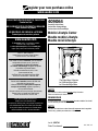 1
1
-
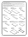 2
2
-
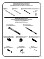 3
3
-
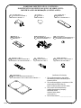 4
4
-
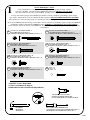 5
5
-
 6
6
-
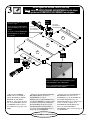 7
7
-
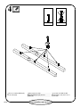 8
8
-
 9
9
-
 10
10
-
 11
11
-
 12
12
-
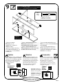 13
13
-
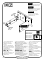 14
14
-
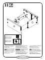 15
15
-
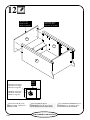 16
16
-
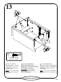 17
17
-
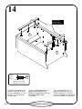 18
18
-
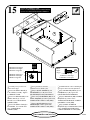 19
19
-
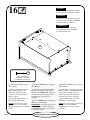 20
20
-
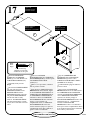 21
21
-
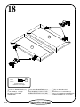 22
22
-
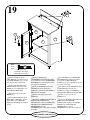 23
23
-
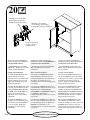 24
24
-
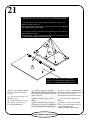 25
25
-
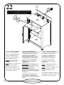 26
26
-
 27
27
-
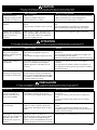 28
28


Sauder 409064 Assembly Instructions Manual
- Tipo
- Assembly Instructions Manual
en otros idiomas
- français: Sauder 409064
- English: Sauder 409064
Artículos relacionados
-
Sauder 408739 Assembly Instructions Manual
-
-
-
-
-
-
-
-
-