Craftsman 917881062 El manual del propietario
- Categoría
- Lanzadores de nieve
- Tipo
- El manual del propietario

Owner's Manual
CRRI:TSMRW
SNOW THROWER
1450 Series Briggs and
Power-Propelled
30" Two-Stage
Model No.
917.881062
• EspaSol, p. 21
CAUTIO ."
Read and follow all
Safety Rules and Instructions
before operating this equipment
Stratton
Engine
Sears, Roebuck and Co., Hoffman Estates, IL 60179 U.S.A.
Visit our Craftsman website: www.sears.com/craftsman

IMPORTANT
Safe Operation Practices for Walk=Behind Snow Throwers
This snow thrower is capable of amputating hands and feet and throwing objects.
Failure to observe the following safety instructions could result in serious injury.
&
Look for this symbol to point out im-
portant safety precautions. It means
CAUTION!!! BEOOMEALERT!!! YOUR
SAFETY IS INVOLVED.
&
WARNING: Always disconnect spark
plug wire and place it where it cannot
contact plug in order to prevent acci-
dental starting when setting up, trans-
porting, adjusting or making repairs.
WARNING: This snow thrower is for
use on sidewalks, driveways and other
ground level surfaces. Caution should
be exercised while using on sloping sur-
faces, Do not use snow thrower on
surfaces above ground level such as
roofs of residences, garages, porches
or other such structures or buildings.
WARNING: Snow throwers have ex-
posed rotating parts, which can cause
severe injury from contact, or from ma-
terial thrown from the discharge chute.
Keep the area of operation clear of all
persons, small children and pets at all
times including startup.
CAUTION: Muffler and other engine
parts become extremely hot during
operation and remain hot after engine
has stopped. To avoid severe burns on
contact, stay away from these areas.
WARNING: Engine exhaust, some of
its constituents, and certain vehicle
components contain or emit chemi-
cals known to the State of California
to cause cancer and birth defects or
other reproductive harm.
Training
1. Read, understand and follow all instructions on the
machine and in the manual(s) before operating this
unit. Be thoroughly familiar with the controls and the
proper use of the equipment. Know how to stop the
unit and disengage the controls quickly.
2. Never allow children to operate the equipment. Never
allow adults to operate the equipment without proper
instruction.
3. Keep the area of operation clear of all persons, par-
ticularly small children.
4. Exercise caution to avoid slipping or falling, especially
when operating the snow thrower in reverse.
Preparation
1. Thoroughly inspect the area where the equipment is
to be used and remove all doormats, sleds, boards,
wires, and other foreign objects.
2. Disengage all clutches and shift into neutral before
starting the engine (motor).
3. Donotoperatethe equipmentwithoutwearing adequate
winter garments. Avoid loose fitting clothing that can
get caught in moving parts. Wear footwear that will
improve footing on slippery surfaces.
4. Handle fuel with care; it is highly flammable
(a) Use an approved fuel container.
(b) Never add fuel to a running engine or hot en-
gine.
(c) Fill fuel tank outdoors with extreme care. Never fill
fuel tank indoors.
(d) Never fill containers inside a vehicle or on a truck
or trailer bed with a plastic liner. Always place
containers on the ground, away from your vehicle,
before filling.
(e) When practical, remove gas-powered equipment
from the truck or trailer and refuel it on the ground.
If this is not possible, then refuel such equipment
on a trailer with a portable container, rather than
from a gasoline dispenser nozzle.
5,
6,
7.
(f) Keep the nozzle in contact with the rim of the fuel
tank or container opening at all times, until refuel-
ing is complete. Do not use a nozzle lock-open
device.
(g) Replace gasoline cap securely and wipe up spilled
fuel.
(h) If fuel is spilled on clothing, change clothing im-
mediately.
Use extension cords and receptacles as specified by
the manufacturer for all units with electric drive motors
or electric starting motors.
Adjust the collector housing height to clear gravel or
crushed rock surface.
Never attempt to make any adjustments while the
engine (motor) is running (except when specifically
recommended by manufacturer).
Always wear safety glasses or eye shields during op-
eration or while performing an adjustment or repair to
protect eyes from foreign objects that may be thrown
from the machine.
Operation
1. Do not put hands or feet near or under rotating parts.
Keep clear of the discharge opening at all times.
2. Exercise extreme caution when operating on or cross-
ing gravel drives, walks, or roads. Stay alert for hidden
hazards or traffic.
3. After striking a foreign object, stop the engine (motor),
remove the wire from the spark plug, disconnect the
cord on electric motors, thoroughly inspect the snow
thrower for any damage, and repair the damage before
restarting and operating the snow thrower.
4. If the unit should start to vibrate abnormally, stop the
engine (motor) and check immediately for the cause.
Vibration is generally a warning of trouble.
5. Stop the engine (motor) whenever you leave the oper-
ating position, before unclogging the collector/impeller
housing or discharge chute, and when making any
repairs, adjustments or inspections.

6. Whencleaning,repairingorinspectingthesnowthrower,
stoptheengineandmakecertainthecollector/impel-
lerandall movingpartshavestopped.Disconnect
thesparkplugwireandkeepthewireawayfromthe
plug.topreventsomeonefromaccidentallystartingthe
engine.
7. Donotruntheengineindoors,exceptwhenstarting
theengineandfortransportingthesnowthrowerinor
outofthebuilding.Opentheoutsidedoors;exhaust
fumesaredangerous.
8. Exerciseextremecautionwhenoperatingonslopes.
9. Neveroperatethesnowthrowerwithoutproperguards,
andothersafetyprotectivedevicesinplaceandwork-
ing.
10.Neverdirectthedischargetowardpeopleor areas
wherepropertydamagecanoccur.Keepchildrenand
othersaway.
11.Donotoverloadthemachinecapacitybyattempting
toclearsnowattoofastarate.
12.Neveroperatethemachineathightransportspeeds
onslipperysurfaces.Lookbehindandusecarewhen
operatinginreverse.
13.Disengagepowertothecollector/impellerwhensnow
throweristransportedornotinuse.
14.Useonlyattachmentsandaccessoriesapprovedby
themanufacturerofthesnowthrower(suchaswheel
weights,counterweights,orcabs).
15.Neveroperatethesnowthrowerwithoutgoodvisibility
orlight.Alwaysbesureofyourfooting,andkeepafirm
holdonthehandles.Walk;neverrun.
16.Nevertouchahotengineormuffler.
Clearing a Clogged Discharge Chute
Hand contact with the rotating impeller inside the discharge
chute is the most common cause of injury associated with
snow throwers. Never use your hand to clean out the dis-
charge chute. To clear the chute:
1. SHUTTHE ENGINE OFF!
2. Wait 10 seconds to be sure the impeller blades have
stopped rotating.
3. Always use a clean-out tool, not your hands.
Maintenance and Storage
1. Check shear bolts and other bolts at frequent intervals
for proper tightness to be sure the equipment is in safe
working condition.
2. Never store the machine with fuel in the fuel tank
inside a building where ignition sources are present
such as hot water heaters, space heaters, or clothes
dryers. Allow the engine to cool before storing in any
enclosure.
3. Always refer to operator's manual for important details
if the snow thrower is to be stored for an extended
period.
4. Maintain or replace safety and instruction labels, as
necessary.
5. Run the machine a few minutes after throwing snow
to prevent freeze-up of the collector/impeller.
TABLE OF CONTENTS
SAFETY RULES ........................................................ 2-3
PRODUCT SPECIFICATIONS ...................................... 4
CUSTOMER RESPONSiBiLITIES ................................ 4
WARRANTY .................................................................. 4
ASSEMBLY / PRE-OPERATION ............................... 6-8
OPERATION ............................................................ 9=14
MAINTENANCE ..................................................... 15-16
MAINTENANCE SCHEDULE ..................................... 15
SERVICE AND ADJUSTMENTS ........................... 17=19
STORAGE ................................................................... 19
TROUBLESHOOTING ................................................ 20
REPAIR PARTS ..................................................... 40-55
SEARS SERVICE ................................... BACK COVER

UMITED2=YEARWARRANTY ON CRAFTSMAN SNOW THROWER
When used and maintained according to the operator's manual instructions, if this snow thrower fails due to a
defect in material or workmanship within two years from the date of purchase, call 1-800-4-MY-HOME® to arrange
for free repair.
During the first 30 days of purchase, there will be no charge to service the product in your home. For your
convenience, in-home warranty service will still be available after the first 30 days of purchase, but a trip charge
will apply. This charge will be waived if you transport the product to an authorized Craftsman drop-off location, For
the nearest authorized location, call 1-800-4-MY-HOME®,
Warranty coverage does not include:
• Expendable items that become worn during normal use, including but not limited to spark plugs, shear pins, belts,
• Standard maintenance servicing, oil changes, or tune-ups.
• Tire replacement or repair caused by punctures from outside objects, such as nails, thorns, stumps, or glass.
• Repairs necessary because of operator abuse, including but not limited to damage caused by impacting objects
that bend the frame, crankshaft or auger, or over-speeding the engine.
• Repairs necessary because of operator negligence, including but not limited to damage caused by improper
storage, failure to use the proper grade and amount of engine oil, or failure to maintain the equipment according
to the instructions contained in the operator's manual
• Engine (fuel system) cleaning or repairs necessary because of fuel determined to be contaminated or oxidized
(stale). In general, fuel should be used within 30 days of its purchase date.
• Normal deterioration and wear of the exterior finishes, or product label replacement,
This warranty applies for only 90 days if this product is used for commercial or rental purposes.
This warranty applies only while this product is within the United States.
This warranty gives you specific legal rights, and you may also have other rights, which vary, from state to state.
Seats, Roebuck And Co., Hoffman Estates, IL 60179
CONGRATULATIONS on your purchase of a new snow
thrower. It has been designed, engineered and manufac-
tured to give best possible dependability and performance.
Should you experience any problem you cannot eas-
ily remedy, please contact your nearest Sears Parts &
Repair Center. We have competent, well-trained tech-
nicians and the proper tools to service or repair this unit.
Please read and retain this manual. The instructions
will enable you to assemble and maintain your snow
thrower properly. Always observe the "SAFETY RULES",
SERIAL NUMBER:
DATE OFPURCHASE:
THE MODELAND SERIAL NUMBERSWILL BE FOUND
ONA DECALATTACH EDTOTHE REAR OFTHE SNOW
THROWER HOUSING.
YOUSHOULDRECORDBOTHSERIALNUMBERAND
DATE OF PURCHASE AND KEEPIN A SAFE PLACE
FOR FUTURE REFERENCE.
PRODUCT SPECiFiCATiONS
Gasoline Capacity 3.0 Quarts
and Type: Unleaded Regular only
Oil Type SAE 5W-30 or 10W-30
(API SG-SL): Synthetic SAE 5W-30
Oil Capacity: 18 Ounces
Spark Plug: Champion RJ19LM
Gap: 0,030"
CUSTOMER RESPONSIBiLITiES
• Read and observe the safety rules.
• Follow a regular schedule in maintaining, caring for
and using your snow thrower.
• Follow the instructions under "Maintenance" and "Stor-
age" sections of this owner's manual.

PARTS PACKED SEPARATELY I CARTON
(1) POWER
CORD
(1) FUEL STABiLiZER PACKET
START I
(2) SAFETY iGNiTiON KEYS
(1) MULTi=
WRENCH
(1) DISCHARGE CHUTE
(1) AUGER CONTROL ROD
(1) TRACTION DRIVE CONTROL ROD _
EXTRA SHEAR BOLTS AND NUTS
(2) SHEAR BOLTS 1/4=20 x 1=3/4
©
(2) SPACERS (2) LOCKNUTS
1/4=20
7
I
I
I
I
I
ROTATOR HEAD MOUNTING
(1) WASHER 3/8 (1) LOCKNUT 3/8
I
I
I
I
I
J
(3) RETAINER
SPRINGS
CHUTE DEFLECTOR REMOTE CONTROL
(1) LOCKNUT
5/16=18
(1) CARRIAGE
BOLT 5/16=18 × 5/8
(1) LOCKNUT (1) NYLON
1/4=20 WASHER
(1) SHOULDER
BOLT 1/4=20 (1) SPRING

AS / RE-O ERATION
Read these instructions and this manual in its entirety
before you attempt to assemble or operate your new
snow thrower. Reading the entire manual will familiar=
ize you with the unit, which will assist you in assembly,
operation and maintenance of the product.
Your new snow thrower has been assembled at the factory
with the exception of those parts left unassembled for ship-
ping purposes. All parts such as nuts, washers, bolts, etc.,
necessary to complete the assembly have been placed in
the parts bag. To ensure safe and proper operation of your
snow thrower, all parts and hardware you assemble must
be tightened securely. Use the correct tools as necessary
to ensure proper tightness.
REMOVE SNOW THROWER FROM CARTON
1. Remove all accessible loose parts and parts boxes
from carton.
2. Cut down all four corners of carton and lay panels flat.
3. Remove the two (2) screws securing the auger housing
to the pallet.
4. Remove all packing materials except plastic tie holding
speed control rod to lower handle.
5. Remove the two (2) plastic ties securing upper handle
to pallet.
6. Remove snow thrower from carton and check carton
thoroughly for additional loose parts.
HOW TO SET UP YOUR SNOW THROWER
TOOL BOX (See Fig. 10)
A toolbox is provided on your snow thrower. The toolbox is
located on top of the belt cover. Store the extra shear bolts,
nuts and multi-wrench provided in parts bag in the toolbox.
NOTE: The multi-wrench may be used for assembly of the
chute rotator head to snow thrower and making adjustments
to the skid plates.
UNFOLD UPPER HANDLE
1. Raise upper handle tothe operating position and tighten
handle knobs securely.
INSTALL SPEED CONTROL ROD (See Figs. 1and 2)
1. Remove plastic tie securing rod to lower handle.
2. Insert rod into speed control bracket and secure with
retainer spring.
UPPER
HANDLE
HANDLE
KNOB
LOWER
HANDLE
/' /
/ ,/
i _ _ i
FIG. 1
SPEED CONTROL ROD
RETAINER
SPRING
SPEED SPEED
CONTROL CONTROL
BRACKET LEVER
FIG. 2

AS / RE-O ERATION
INSTALL TRACTION DRIVE CONTROL ROD
(See Figs. 3 and 4)
The traction drive control rod has the long loop on the end
of the spring as shown.
1. Slide rubber sleeve up rod and hook end of spring into
pivot bracket with loop opening down as shown.
2. With top end of rod positioned under left side of control
panel, push rod down and insert top end of rod into hole
in drive control bracket. Secure with retainer spring.
INSTALL AUGER CONTROL ROD (See Figs. 5 and 6)
The auger control rod has the short loop on the end of the
spring as shown.
1. Slide rubber sleeve up rod and hook end of spring into
control arm with loop opening up as shown.
2. With top end of rod positioned under right side of
control panel, push down on rod and insert end of rod
into hole in auger control bracket. Secure with retainer
spring.
FIG. 3
RETAINER
SPRING
CONTROL
BRACKET
FIG, 4
AUGER
ROD
RUBBER
SLEEVE
CONTROL
ARM
FIG. 5
AUGER CONTROL ROD AUGER
CONTROL
RETAINER LEVER
SPRING \
CONTROL
BRACKET
FIG. 6

AS BLY / RE..O ERATION
iNSTALL DISCHARGE CHUTE / CHUTE ROTATOR
HEAD (See Fig. 7)
NOTE: The multi-wrench provided in your parts bag may
be used to install the chute rotator head,
1, Place discharge chute assembly on top of chute base
with discharge opening toward front of snow thrower,
2, Position chute rotator head overchute bracket, Ifneces-
sary, rotate chute assembly toalign square and pin on un-
derside of chute rotator head with holes inchute bracket,
3, With chute rotator head and chute bracket aligned,
position chute rotator head on pin and threaded stud
of mounting bracket,
4, Install 3/8 washer and Iocknut on threaded stud and
tighten securely,
PIN
STUD
CHUTE
BRACKET
ROTATOR HEAD
CHUTE MOUNTING
ROTATOR HEAD BRACKET
FiG. 7
iNSTALL CHUTE DEFLECTOR REMOTE CONTROL
(See Figs. 8 and 9)
1, Install remote cable bracket to discharge chute with
5/16-18 carriage bolt and 5/16-18 Iocknut as shown,
Tighten securely,
2, Install remote cable eyelet to chute deflector with
1/4-20 shoulder bolt, nylon washer and 1/4-20 Iocknut
as shown, Tighten securely,
3, Install spring hooks between hex nuts on chute rotator
head and into hole in chute deflector as shown,
SPRING
1/4-20 CHUTE
SHOULDER
HOOK
NYLON BETWEEN
WASHER HEX HUTS
ON CHUTIE
1/4-20 ROTATO R
LOCKNUT
CABLE
EYELET
5/16- ! 8
CARRIAGE
BOLT
L _EMOTE
CABLE
RACKET
5/16-18
LOCKNUT
FiG. 8
//
/
/
/
/'
CHUTE DEFLECTOR
CONTROL LEVER
I
FIG, 9
CHECK TiRE PRESSURE
The tires on your snow thrower were overinflated atthe fac-
tory for shipping purposes. Correct and equal tire pressure
is important for best snow throwing performance,
• Reduce tire pressure to 14-17 PSi (19-24,5 N-m),

OPERATION
KNOW YOUR SNOW THROWER
READ THIS OWNER'S MANUALAND ALL SAFETY RULES BEFORE OPERATING YOUR SNOWTHROWER. Compare
the illustrations with your snow thrower to familiarize yourself with the location of various controls and adjustments, Save
this manual for future reference,
These symbols may appear on your snow thrower or in literature supplied with the product. Learn and understand
their meaning,
ENGINE
OFF
I\1
DANGER ENGINE FAST SLOW CHOKE PRIMER
OR WARNING ON
R
FUEL OIL FORWARD REVERSE
READ AND FOLLOW ALL SAFETY INFORMATION
AND iNSTRUCTiONS BEFORE USE OF THIS PRODUCT.
KEEP THESE INSTRUCTIONS FOR FUTURE REFERENCE.
iGNITiON KEY.
INSERT TO START
AND RUN,
PULL OUT TO STOP.
DISENGAGED
ENGAGED
\ J
SNOW
DISCHARGE
_J
TRACTION
DRIVECONTROL

OPERATION
GASOLINE ELECTRIC AUGER DISCHARGE CHUTE CONTROL LEVER
START BUTTON CONTROL
LEVER DRIVE SPEED DEFLECTOR REMOTE
RECOIL X CONTROL LEVER CONTROL LEVER
\
STARTER
HANDLE
TRACTION
CHUTE DRIVE
CHOKE DEFLECTOR CONTROL
CONTROL LEVER
SAFETY
IGNITION
KEY
ON / OFF
SWITCH
CHUTE
LH TURN
TRIGGER
LIGHT
CLEAN-OUT TOOL
KNOB
NOTE: ITEMS ABOVE
ARE SHOWN IN
THEIR TYPICAL
LOCATION ON THE
ENGINE. ACTUAL
LOCATION MAY VARY
WITH THE ENGINE
ON YOUR UNIT.
\
\
\
TOOLBOX
DRIFT CUTTER
PLATE
AUGERS
FIG. 10
MEETS A,N,S,I, SAFETY REQUIREMENTS
Our snow throwers conform to the standards of the American National Standards institute,
Toolbox - used to store spare shear bolts, Iocknuts and
wrench,
Safety ignition key =must be inserted for the engine to
start and run, Remove when snow thrower is not in use,
Electric start button - used for starting the engine,
Recoil (auxiliary) starter handle-used for starting engine,
Primer - pumps additional fuel from the carburetor to the
cylinder for use when starting a cold engine.
Choke Control - used for starting a cold engine.
ON / OFF switch =used to STOP the engine.
LH and RH turn triggers- used to steer the snow thrower.
10
Drive speed control lever = used to select forward or
reverse motion and speed of snow thrower,
Traction drive control lever- used to engage power-pro-
pelled forward or reverse motion of snow thrower,
Auger control lever - used to engage auger motion
(throw snow),
Discharge chute control lever - used to change the
direction the snow is thrown,
Deflector remote control lever - used to change the
distance the snow is thrown,
Skid plate - used to adjust height ofscraper bar from ground,
Drift cutter - used to cut through deep snowdrifts,

OPERATION
The operation of any snow thrower can result
in foreign objects thrown into the eyes, which
can result insevere eyedamage. Always wear
safety glasses or eye shields while operating
your snow thrower or performing any adjust-
ments or repairs. We recommend standard safety glasses
or a wide vision safety mask worn over spectacles.
HOW TO USE YOUR SNOW THROWER
Know how to operate all controls before adding fuel or
attempting to start the engine.
STOPPING
TRACTION DRIVE
• Release traction drive control lever to stop the forward
or reverse movement of the snow thrower.
AUGER
• Release the auger control lever to stop throwing snow.
ENGINE
1. Move ON / OFF switch to "OFF" position.
2. Remove (do not turn) safety ignition key to prevent
unauthorized use.
NOTE: Never use choke to stop engine.
TO USE CHOKE CONTROL (See Fig. 11)
The choke control is located on the engine. Use the choke
control whenever you are starting a cold engine. Do not
use to start a warm engine.
• To engage choke, turn knob counterclockwise. Slowly
turn knob clockwise to disengage.
FIG. 11
TO CONTROL SNOW DISCHARGE (See Fig, 12)
WARNING: Snow throwers have ex-
posed rotating parts, which can cause
severe injury from contact, or from ma-
terial thrown from the discharge chute.
Keep the area of operation cJear of all
persons, small children and pets at all
times including startup.
WARNING: if the discharge chute or
auger become clogged, shut-off engine
and wait for all moving parts to stop, Use
the clean=out tool, NOT YOUR HANDS,
to unclog the chute and/or auger.
The DIRECTION inwhich snow isto be thrown iscontrolled
by the discharge chute control lever.
• Tochangethe discharge chute position, press downward
on discharge chute control lever and move lever left
or right until chute is in desired position. Be sure lever
springs back and locks into desired position.
The DISTANCE that snow is thrown is controlled by the
position of the chute deflector. Set the deflector low to
throw snow a short distance; set the deflector higher to
throw snow farther.
Press downward on chute deflector control lever and
move lever forward to lower the deflector and decrease
the distance. Move lever back to raise the deflector
and increase the distance. Be sure lever springs back
and locks into desired position.
DlSCHARGECHUTE
CONTROLLEVER
CHUTE DEFLECTOR
REMOTE CONTROLLEVER
FIG, 12
11

OPERATION
TO THROW SNOW (See Fig, 13)
The auger rotation is controlled by the auger control lever
located on the right side handle.
• Squeeze auger control lever to handle to engage the
auger and throw snow.
• Release the auger control lever to stop throwing snow.
TO MOVE FORWARD AND BACKWARD (See Fig. 15)
SELF-PROPELLING, forward and reverse movement of
the snow thrower, is controlled by the traction drive control
lever located on the left side handle.
• Squeeze traction drive control lever to handle to engage
the drive system,
• Release traction drive control lever to stop the forward
or reverse movement of the snow thrower,
SPEED and DIRECTION are controlled by the drive speed
control lever.
FIG, 13
USING THE CLEAN-OUT TOOL (See Fig, 14)
In certain snow conditions, the discharge chute may be-
come clogged with ice and snow, Use the clean-out tool
to dislodge this blockage,
When cleaning, repairing, or inspecting, make
certain all controls are disengaged and the au-
ger/impeller and all moving parts have stopped,
Disconnect the spark plug wire and keep the
wire away from the spark plug to prevent ac-
cidental starting,
• Releasethe auger control lever and shut offthe engine.
• Removethe clean-out tool from it'smounting clip. Grasp
the tool firmly bythe handle and push and twist the tool
into the discharge chute to dislodge the blockage.
After the packed snow has been dislodged, return the clean-
out tool to it's mounting clip by pushing it into the clip.
• Make sure the discharge chute is pointed in a safe di-
rection (no vehicles, buildings, people, or other objects
are in the direction of discharge) before restarting the
engine.
• Restart the engine, then squeeze the auger control
lever to the handle to clear snow from the auger hous-
ing and the discharge chute.
DISCHARGECHUTE
TOOL
MOUNTING
I
• Press downward on the speed control lever and move
lever to desired position BEFORE engaging the trac-
tion drive control lever. Be sure lever springs back and
locks into desired position,
• Slower speeds are for heavier snow and faster speeds
are for light snow and transporting the snow thrower. It
is recommended that you use a slower speed until you
are familiar with the operation of the snow thrower.
NOTE: When both traction drive and auger control levers
are engaged, the traction drive control lever will lock the
auger control lever in the engaged position. This will allow
you to release your right hand from the handle and adjust
the discharge chute direction without interrupting the snow
throwing process,
TRACTION DRIVE //_
CONTROLLEVER
FIG. 15
POWER STEERING OPERATION (See Fig, 16)
Steering triggers are used to assist in steering your snow
thrower. The triggers are located on the underside of each
handle. When atrigger is squeezed, itdisengages the drive
wheel on that side of snow thrower and allows it to turn in
that direction.
• To turn left- squeeze left side trigger,
• To turn right - squeeze right side trigger,
LH TURN
TRIGGER
FIG, 14 12 FIG. 16

OPERATION
TO ADJUST SKiD PLATES (See Fig. 17)
NOTE: The wrench provided in your parts bag may be
used to adjust the skid plates.
Skid plates are located on each side of the auger housing
and adjust the clearance between the scraper bar and the
ground surface. Adjust skid plates evenly to proper height
for current surface conditions. For removal of snow in
normal conditions, such as a paved driveway or sidewalk,
place skid plates in the highest position (lowest scraper
clearance) to give a 5 mm clearance between the scraper
bar and the ground. Use a middle position if the surface
to be cleared is uneven.
NOTE: It is not recommended to operate the snow thrower
over gravel or rocky surfaces. Objects such as gravel, rocks
or other debris, can easily be picked up and thrown by the
impeller, which can cause serious personal injury, property
damage or damage to the snow thrower.
• Ifsnow thrower must be operated over gravel surface,
use extra caution and be sure skid plates are adjusted
to lowest (highest scraper clearance) position.
1. Shut off engine and wait for all moving parts to stop.
2. Adjust skid plates by loosening the hex nuts, then mov-
ing skid plate to desired position. Be sure both plates
are adjusted evenly. Tighten securely.
(LOW GROUND
_)
AUGER
HOUSING
SCRAPER BAR
I HEX
_¢ NUTS PLATE
LOW POSITION (HIGH GROUND CLEARANCE)
FIG, 17
SCRAPER BAR
The scraper bar is not adjustable, but is reversible. After
considerable use it may become worn. When it has worn
almost to the edge of the housing, it can be reversed,
providing additional service before requiring replacement,
Replace a damaged or worn scraper bar.
TO USE DRIFT CUTTERS (See Fig. 18)
Use the drift cutters to cut through deep snowdrifts that are
higher than the front of the snow thrower.
• Loosen upper adjustment nut enough to allow drift
cutter to be raised to highest position and tighten nut
securely. Repeat for opposite side of snow thrower.
• When not using drift cutters, loosen adjustment nut,
lower to storage position and tighten nut securely.
AUGER
HOUSING
STcORTIAoGE_
DRIFT
CUTTER
ADJUST
MENT NUT
BEFORE STARTING THE ENGINE
CHECK ENGINE OiL LEVEL (See Fig. 19)
The engine on your snow thrower has been shipped, from
the factory, already filled with oil.
1. Check engine oil with snow thrower on level ground.
2. Remove oil fill cap/dipstick and wipe clean, reinsert
the dipstick and screw tight, wait for a few seconds,
remove and read oil level. If necessary, add oil until
"FULL:.'mark on dipstick is reached. Do not overfill.
• Tochange engine oil, see "TO CHANGE ENGINE OIE'
in the Maintenance section of this manual.
ADD GASOLINE (See Fig. 19)
• Fill fuel tank to bottom of tank filler neck. Do not over-
fill. Use fresh, clean, regular unleaded gasoline with
a minimum of 87 octane. Do not mix oil with gasoline.
Purchase fuel in quantities that can be used within 30
days to assure fuel freshness.
WARNING: Wipe off any spilled oil or
fuel. Do not store, spill or use gasoline
near an open flame.
CAUTION: Alcohol blended fuels (called gas-
ohol or using ethanol or methanol) can attract
moisture which leads to separation and for-
mation of acids during storage. Acidic gas can
damage the fuel system of an engine while in
storage. To avoid engine problems, the fuel
system should be emptied before storage of
30 days or longer. Empty the gas tank, start
the engine and let it run until the fuel lines and
carburetor are empty. Use fresh fuel next sea-
son. See Storage instructions for additional
information. Never use engine or carburetor
cleaner products in the fuel tank or permanent
damage may occur.
CHOKE ENGINE OIL GASOLINE
CONTROL FILL CAP / DiPSTiCK FILLER CAP
STARTER
BUTTON
PRIMER RECOIL
STARTER
SAFETY HANDLE
IGNITION ON / OFF
KEY SWITCH
NOTE: ALL ITEMS ARE SHOWN IN THEIR TYPICAL LOCATION.
ACTUAL LOCATION MAY VARY WITH ENGINE ON YOUR UNIT.
FIG, 18 13 FIG, 19

OPERATION
TO START ENGINE 5. Pull recoil starter handle quickly. Do not allow starter
Your snow thrower engine is equipped with both a 120 Volt
A.C. electric starter and a recoil starter. The electric starter
is equipped with a three-wire power cord and plug and is
designed to operate on 120 Volt A.C. household current.
• Be sure your house is a 120 Volt A.C. three-wire
grounded system. If you are uncertain, consult a
licensed electrician.
WARNING: Do not use the electric
starter if your house is not a 120 Volt
A.C. three=wire grounded system. Se=
rious personal injury or damage to your
snow thrower could result.
COLD START- ELECTRIC STARTER
1. Insert safety ignition key (packed separately in parts
bag) into ignition slot until itclicks. DO NOTtum the key.
Keep the extra safety ignition key in a safe place.
2. Place ON / OFF switch in "ON" position.
3. Rotate choke control to "FULl" position.
4. Connect the power cord to the engine.
5. Plug the other end of the power cord into a three-hole
grounded 120 Volt A.C. receptacle.
NOTE: Do not use primer when starting engine with the
electric starter.
6. Push starter button until engine starts.
IMPORTANT: Do not crank engine more than five con-
tinuous seconds between each time you try to start. Wait
5 to 10 seconds between each attempt.
7. When the engine starts, release the starter button and
slowly move the choke control to the "OFF" position.
8. Disconnect the power cord from the receptacle first,
then from the engine.
Allow the engine to warm up for a few minutes. Engine will
not develop full power until it has reached normal operat-
ing temperature.
WARM START - ELECTRIC STARTER
Follow the steps above, keeping the choke control in the
"OFF" position.
COLD START - RECOIL STARTER
1. Insert safety ignition key (packed separately in parts
bag) into ignition slot until itclicks. DO NOTturn the key.
Keep the extra safety ignition key in a safe place.
2. Place ON / OFF switch in "ON" position.
3. Rotate choke control to "FULl" position.
4. Push the primer four (4) times if the temperature is
below 15°F, or two (2) times if temperature is between
15° and 50°R If temperature is above 50°F, priming is
not necessary.
NOTE: Over priming may cause flooding, preventing the
engine from starting. If you do flood the engine, wait a few
minutes before attempting to start and DO NOT push the
primer.
6,
rope to snap back.
When the engine starts, release the recoil starter handle
and slowly move the choke control to the "OFF" posi-
tion.
Allow the engine to warm up for a few minutes. Engine will
not develop full power until it has reached normal operat-
ing temperature.
WARM START- RECOIL STARTER
Follow the steps above, keeping the choke in the "OFF"
position. DO NOT push the primer.
BEFORE STOPPING
Run the engine for a few minutes to help dry off any mois-
ture on the engine.
IF RECOIL STARTER HAS FROZEN
Ifthe recoil starter has frozen and will not turn the engine,
proceed as follows:
1. Grasp the recoil starter handle and slowly pull as much
rope out of the starter as possible.
2. Release the recoil starter handle and let it snap back
against the starter.
If the engine still fails to start, repeat the above steps or
use the electric starter.
SNOW THROWING TiPS
• Go slower in deep, freezing or heavy wet snow. Use
the drive speed control, NOT the ON / OFF switch, to
adjust speed.
• It is easier and more efficient to remove snow imme-
diately after it falls.
• The best time to remove snow is the early morning. At
this time the snow is usually dry and has not been ex-
posed to the direct sun and warming temperatures.
• Slightly overlap each successive path to ensure all
snow will be removed.
Throw snow downwind whenever possible.
Adjust the skid plates to proper height for current snow
conditions. See "TO ADJUST SKID PLATES" in this
section of this manual.
• For extremely heavy snow, reduce the width of snow
removal by overlapping previous path and moving
slowly.
, Keep engine clean and clear of snow during use. This
will help air flow and extend engine life.
, After snow-throwing iscompleted, allow engine to run for
a few minutes to melt snow and ice off the engine.
• Clean the entire snow thrower thoroughly after each
use and wipe dry so it is ready for next use.
WARNING: Do not operate snow
thrower ifweather conditions impair vis-
ibility, Throwing snow during a heavy,
windy snowstorm can blind you and be
hazardous to the safe operation of the
snow thrower.
14

CE
HT Check for Loose Fasteners I_ I_
R Clean / Inspect Snow Thrower t1_ If
O
W Check/Replace V-Belts I_
Lubrication Chart I_ If
Check Engine Oil Level
E
N Change Engine Oil
Inspect Muffler
N Check / Replace Spark Plug
E
Empty Fuel Tank
v'
t/
v'
v'
GENERAL RECOMMENDATIONS
The warranty on this snow thrower does not cover items
that have been subjected to operator abuse or negligence.
To receive full value from the warranty, operator must
maintain snow thrower as instructed in this manual. Some
adjustments will need to be made periodically to properly
maintain your snow thrower.
At least once a season, check to see if you should make
any of the adjustments described in the Service and Ad-
justments section of this manual.
• At least once a year, you should replace the spark plug
and check belts for wear. A new spark plug will help
your engine run better and last longer.
• Follow the maintenance schedule in this manual.
NOTE: Use only Original Equipment Manufacturer (OEM)
parts to service this unit. Failure to do so can cause the unit
to malfunction and pose a risk of injury to the operator.
LUBRICATION CHART
(_ SAE 5W=30 Motor Oil
(_) See "ENGINE" in
Maintenance section
(_) General
Purpose
Grease
@ Engine oil
BEFORE EACH USE
1, Check engine oil level.
2. Check for loose fasteners.
3, Check controls to be sure they are functioning properly.
LUBRICATION
Keep your snow thrower well lubricated
(See "LUBRICATION CHART"),
Auger
grease fittings
O Pivot
points
SNOW THROWER
Always observe the safety rules when performing any
maintenance.
TIRES
• Maintain proper air pressure in both tires (14-17 RS.I.
/ 19-24.5 N-m).
Keep tires free of gasoline and oil, which can harm
rubber.
NOTE: To seal tire punctures and prevent flat tires due
to slow leaks, tire sealant may be purchased from your
local parts dealer. Tire sealant also prevents tire dry rot
and corrosion.
15

E
V-BELTS TO CHANGE ENGINE OIL
Check V-belts for deterioration and wear after every 50
hours of operation and replace if necessary. The belts
are not adjustable. Replace belts ifthey begin to slip from
wear. (See "TO REMOVE BELT COVER" in the Service
and Adjustments section of this manual).
The V-belts on your snow thrower are ofspecial construction
and should be replaced byoriginal equipment manufacturer
(OEM) belts available from your nearest dealer. Using other
than OEM belts can cause personal injury or damage to
the snow thrower.
AUGER GEAR CASE
• The gear case was filled with lubricant to the proper
level at the factory. The only time the lubricant needs
attention is if service has been performed on the gear
case.
• Iflubricant is required, use only Ronex ED #1 grease.
TRACTION DRIVE SYSTEM
DO NOT lubricate the drive components inside the snow
thrower. The sprockets, hex shafts, drive disc and friction
wheel require no lubrication. The bearings and bushings
are lifetime lubricated and require no maintenance.
CAUTION: Any lubricating of the above compo=
nents can cause contamination of the friction
wheel and damage to the drive system of your
snow thrower.
ENGINE
LUBRiCATiON
Use only high quality detergent oil rated with API service
classification SG-SL Select the oil's SAE viscosity grade
according to your expected operating temperature.
SAE VISCOSITY GRADES
°F -20 0 30 32 40
i°C -3'0 -20 =1'0 0
TEMPERATURE RANGE ANTICIPATED
BEFORE NEXT OiL CHANGE
10
NOTE: Although multi-viscosity oils (5W30, 10W30 etc.)
improve starting in cold weather, these multi-viscosity oils
will result in increased oil consumption when used above
32°F/0°C. Check your engine oil level more frequently to
avoid possible engine damage from running low on oil.
Change the oil after every 25 hours of operation or at least
once a year if the snow thrower is not used for 25 hours
in one year.
Check the crankcase oil level before starting the engine and
after each five (5) hours of continuous use. Tighten oil fill
cap / dipstick securely each time you check the oil level.
Determine temperature range anticipated before next oil
change. All oil must meet API service classification SG-SL.
• Be sure snow thrower is on level surface.
• Oil will drain more freely when warm.
• Catch oil in a suitable container.
NOTE: The left side wheel may be removed from snow
thrower for easier access to the oil drain plug and place-
ment of a suitable container. The unit tilted, resting on the
frame with the left wheel removed, will help drain any oil
trapped inside the engine. (See "TO REMOVE WHEELS"
in the Service and Adjustments section of this manual).
1. Remove safety ignition key and disconnect spark plug
wire from spark plug. Place wire where itcannot come
in contact with plug.
2. Clean area around drain plug.
3. Remove drain plug and drain oil in a suitable container.
4. Install drain plug and tighten securely.
5. Wipe off any spilled oil from snow thrower and engine.
6. Install left wheel (if removed for draining oil). Be sure to
install klick pin into proper hole in wheel axle (See "TO
REMOVE WHEELS" in the Service and Adjustments
section of this manual).
7. Remove oil fill cap/dipstick. Be careful not to allow dirt
to enter the engine.
8. Refill engine with oil through oil dipstick tube. Pour
slowly. Do not overfill. For approximate capacity see
"PRODUCT SPECIFICATIONS"section of this manual.
9. Use gauge on oil fill cap/dipstick for checking level.
Be sure dipstick cap istightened securely for accurate
reading. Keep oil at "FULL.' line on dipstick.
10. Wipe off any spilled oil.
MUFFLER
Inspect and replace corroded muffler as it could create a
fire hazard and/or damage.
SPARK PLUG
Replace spark plug at the beginning of each season or after
every 100 hours of operation, which ever occurs first. Spark
plug type and gap setting are shown in the "PRODUCT
SPECIFICATIONS" section of this manual.
CLEANING
iMPORTANT: For best performance, keep snow thrower
housing free of any dirt or trash, Clean the outside of your
snow thrower after each use.
-- come in contact with plug,
Keep finished surfaces/wheels free of gasoline, oil, etc.
We do not recommend using a garden hose to clean
your snow thrower unless the electrical system, muffler
and carburetor are covered to keep water out. Water
in engine can result in shortened engine life.
16

SERVICE ADJUSTMENTS
WARNING: To avoid serious injury, before
performing any service or adjustments:
1. Be sure the on/off switch is in the
OFF position.
2, Remove safety ignition key.3. Make sure the augers and all moving
parts have completely stopped.
4. Disconnect spark plug wire from
spark plug and place wire where it
cannot come in contact with plug.
SNOW THROWER
TO ADJUST SNOW THROWER HEIGHT
See "TO ADJUST SKID PLATES" and "SCRAPER BAR"
in the Operation section of this manual.
CHUTEDEFLECTOR
The chute deflector, attached to the top of the discharge
chute, is provided to direct discharging snow away from
the operator. If the deflector becomes damaged, it should
be replaced.
• Tochange direction and/or distance snow isdischarged,
see "TO CONTROL SNOW DISCHARGE" in the Op-
eration section of this manual.
SHEAR BOLTS (See Fig. 20)
AUGER SHEAR BOLTS
Both right and left-hand augers are secured to the auger
shaft with a shoulder/shear bolt and hex nut. Should a for-
eign object or ice become lodged in the augers, the shear
bolts are designed to break, preventing damage to any
other components. If one or both augers do not turn when
auger control lever is engaged, check to see if one or both
of the bolts have sheared. To replace the shear bolts:
1. Disengage all controls and move throttle control to
STOP position or move ON/OFF switch to OFF posi-
tion. Wait for all moving parts to stop.
2. Remove safety ignition key and disconnect spark plug
wire from spark plug. Place wire where itcannot come
in contact with plug.
3. Align hole in auger hub with hole in auger shaft and
install a new 1/4-20 x 2" shoulder/shear bolt. Install
1/4-20 lock nut and tighten securely.
CAUTION: Do not substitute. Use only original
equipment shear bolts as supplied with your
snow thrower.
4. Connect spark plug wire to spark plug. Replace safety
ignition key.
IMPELLER SHEAR BOLTS
The impeller is secured to the impeller shaft with two (2)
capscrew/shear bolts and hex nuts. Should a foreign object
or ice become lodged in the impeller, the capscrews are
designed to break, preventing damage to any other com-
ponents. If impeller does not turn when auger control lever
is engaged, check to see if the capscrews have sheared.
To replace the capscrew/shear bolts:
1. Disengage all controls and move throttle control to
STOP position. Wait for all moving parts to stop.
2. Remove safety ignition key and disconnect spark plug
wire from spark plug. Place wire where it cannot come
in contact with plug.
3. Align holes in impeller hub with holes in impeller shaft
and install two (2) new 1/4-20 x 1-5/8" capscrew/shear
bolts. Install 1/4-20 Iocknuts and tighten securely.
i CAUTION: Do not substitute. Use only original
J equipment capscrew/shear bolts as supplied |
with your snow thrower.
4. Connect spark plug wire to spark plug. Replace safety
ignition key.
FIG, 20
TO REMOVE BELT COVER (See Fig. 21)
1. Remove the two (2) screws securing belt cover to
frame.
2. Remove belt cover.
• Replace belt cover by installing cover and screws and
tighten securely.
FIG, 21
17

SERVICE ADJUSTMENTS
TO REPLACE BELTS (See Fig. 22)
The auger and traction drive belts are not adjustable. Ifthe
belts are damaged or begin to slip from wear, they should
be replaced. Itis recommended that the belt(s) be replaced
by a Sears service centre/department.
NOTE: It is recommended that both the auger and traction
drive belt be replaced at the same time.
The V-belts on your snow thrower are ofspecial construction
and should be replaced byoriginal equipment manufacturer
(OEM) belts available from your nearest Sears service
centre/department. Using other than OEM belts can cause
_ersonal injury or damage to the snow thrower.
WARNING: Belt replacement requires
separation of the snow thrower, While
separating the auger housing from the
frame assembly, it is important that
an assistant stand in the operating
position and hold the snow thrower
handles, Serious personal injury and/or
damage to the unit could occur if the
snow thrower should fall during the belt
changing process.
FRAME AUGER
ASSEMBLY HOUSING
8. RELIEVE TENSION ON TRACTION DRIVE BELT
IDLER and remove traction drive belt from around
pulleys.
HINT: Insert a 3/8" drive ratchet (in the "ON" position) into
the square hole in idler arm and rotate ratchet clockwise
to relieve tension.
9. With tension relieved on idler, install new traction drive
belt around pulleys and inside belt keepers.
10. Install clutch rod in swing plate; secure with hairpin.
11. Place auger belt around and inside the groove of auger
pulley only.
12. While your assistant slowly raises handles to rejoin
the auger housing and frame assembly, pull up on the
auger belt and squeeze sides together above pulley
so belt is fully seated in groove of pulley.
13. Bring snow thrower completely together and check
carefully for proper routing of belts. If auger belt has
become dislodged from the pulley (by catching the idler
arm bracket while bringing snow thrower together),
separate the snow thrower and repeat step 10. Belt
must be fully seated in pulley groove when bringing
the snow thrower together.
14. Install the two (2) hex bolts and tighten securely.
15. INSTALL ENGINE PULLEY- Place belt in pulley groove
and slide pulley on crankshaft. Install flat washer,
Iockwasher and bolt and tighten securely (41-47 N-m
torque). Make sure belt is inside belt keeper.
16. INSTALL BELT COVER and two (2) screws. Tighten
securely.
17. INSTALL DISCHARGE CHUTE - See "INSTALL DIS-
CHARGE CHUTE / CHUTE ROTATER HEAD" in the
Assembly / Pre-Operation section of this manual.
1, REMOVE GASOLINE FROM FUEL TANK - Drain
gasoline from fuel tank into a suitable container, out-
doors, away from fire or flame, Wipe up any spilled
gasoline,
2, REMOVE DISCHARGE CHUTE - Loosen Iocknut
securing chute rotator head to mounting bracket only
enough to allow chute rotator head to be raised and
discharge chute to be removed from snow thrower,
3, REMOVE BELT COVER - See "TO REMOVE BELT
COVER" in this section of this manual,
4. REMOVE ENGINE PULLEY-Removebolt, lockwasher
and flat washer securing pulley to engine crankshaft,
Remove outside (auger) pulley only from crankshaft,
5, SEPARATE SNOW THROWER - With your assistant
standing in the operating position holding the handles,
remove the two (2) bolts holding the auger housing and
frame together,
I WARNING: As the last bolt is removed,
m
&
I have your assistant carefully lower the I
handles down to the ground.
6. REMOVE HAIRPIN FROM CLUTCH ROD and remove
clutch rod from swing plate. Tip swing plate forward.
7. REMOVE AUGER BELT from around pulley.
18
HOLE
AUGER
FRAME ROUSING
FIG. 22

TO REMOVE WHEELS (See Fig. 23)
• Remove the klik pin and remove wheel from axle.
IMPORTANT: When installing wheel, be sure to use the
axle hole closest to the end of the shaft - do not use the
hole in the wheel hub (if equipped), Inner hole in axle and
hole in wheel hub are not used for your model snow thrower,
KLIK PIN (INSTALL
IN OUTER HOLE
OF AXLE ONLY)
OUTER HOLE
AXLE
WHEEL WHEEL HUB
FNG. 23
NOTE: To seal punctures or prevent flat tires due to slow
leaks, tire sealant may be purchased from your local parts
dealer, Tire sealant also prevents tire dry rot and corrosion,
ENGINE
CARBURETOR
Your carburetor is not adjustable. Engine performance
should not be affected at altitudes up to 7,000 feet (2,134
meters), If your engine does not operate properly due to
suspected carburetor problems, take your snow thrower
to a Sears service centre/department,
ENGINE SPEED
Never tamper with the engine governor, which isfactory set
for proper engine speed, Overspeeding the engine above
the factory high speed setting can be dangerous and will
void the warranty, If you think the engine-governed high
speed needs adjusting, contact a Sears Parts & Repair
Center, which has the proper equipment and experience
to make any necessary adjustments,
STO E
Immediately prepare your snow thrower for storage at
the end of the season or if the unit will not be used for 30
days or more,
WARNING: Never store the snow
thrower with gasoline in the tank inside
a building where fumes may reach an
open flame, spark or pilot light as on a
furnace, water heater, clothes dryer or
gas appliance. Allow the engine to cool
before storing in any enclosure.
SNOW THROWER
When snow thrower is to be stored for a period of time,
clean it thoroughly, remove all dirt, grease, leaves, etc,
Store in a clean, dry area.
1, Clean entire snow thrower (See "CLEANING" in the
Maintenance section of this manual),
2, Inspect and replace belts, if necessary (See "TO RE-
PLACE BELTS" inthe Service and Adjustments section
of this manual),
3, Lubricate as shown in the Maintenance section of this
manual,
4, Besurethat all nuts, bolts, screws, and pins are securely
fastened. Inspect moving parts for damage, breakage
and wear, Replace if necessary,
5, Touch up all rusted or chipped paint surfaces; sand
lightly before painting,
ENGINE
FUEL SYSTEM
IMPORTANT: Itis important to prevent gum deposits from
forming in essential fuel system parts such as carburetor,
fuel hose, or tank during storage, Alcohol blended fuels
(called gasohol or using ethanol or methanol) can attract
moisture which leads to separation and formation of acids
during storage. Acidic gas can damage the fuel system of
an engine while in storage,
19
• Empty the fuel tank by starting the engine and letting
it run until the fuel lines and carburetor are empty,
• Never use engine or carburetor cleaner products in
the fuel tank or permanent damage may occur,
• Use fresh fuel next season,
NOTE: Fuel stabilizer is an acceptable alternative in min-
imizing the formation of fuel gum deposits during storage,
Add stabilizer to gasoline infuel tank or storage container.
Always follow the mix ratio found on stabilizer container,
Run engine at least 10 minutes after adding stabilizer to
allow the stabilizer to reach the carburetor. Do not empty
the gas tank and carburetor if using fuel stabilizer,
ENGINE OIL
Drain oil (with engine warm) and replace with clean engine
oil, (See "ENGINE" in the Maintenance section of this
manual),
3,
4,
CYLINDER
1, Remove spark plug,
2, Pour approximately one ounce (30 ml) of oil through
spark plug hole into cylinder,
Pull recoil starter handle slowly a few times to distribute
oil,
Replace with new spark plug,
OTHER
• Remove safety ignition key; store it in a safe place,
• Do not store gasoline from one season to another,
• Replace your gasoline can if your can starts to rust.
Rust and/or dirt in your gasoline will cause problems,
• Ifpossible, store your snow thrower indoors and cover
it to protect it from dust and dirt,
• Cover your snow thrower with a suitable protective
cover that does not retain moisture, Do not use plastic,
Plastic cannot breathe, which allows condensation to
form and will cause your snow thrower to rust,
IMPORTANT: Never cover snow thrower while engine/ex-
haust area is still warm,

TROU OOTING
See appropriate section in manual unless directed to a Sears service centre/department.
PROBLEM
Does not start
Loss of power
Engine idles or
runs roughly
Excessive
vibration
Recoil starter
is hard to pull
Loss of traction
drive / slowing
of drive speed
Loss of snow
discharge or
slowing of
snow discharge
CAUSE
1. Fuel shut-off valve (if so
equipped) in OFF position.
2. Safety ignition key
is not inserted.
3. Out of fuel.
4. Throttle in STOP position
(or ON/OFF switch is OFF).
5. Choke in OFF position.
6. Primer not depressed.
7. Engine is flooded.
8. Spark plug wire is
disconnected.
9. Bad spark plug.
10. Stale fuel.
11. Water in fuel.
1. Spark plug wire loose.
2. Throwing too much snow.
3. Fuel tank cap is covered
with ice or snow.
4. Dirty or clogged muffler.
1. Choke is in FULL position.
2. Blockage in fuel line.
3. Stale fuel.
4. Water in fuel.
5. Carburetor is in need of
adjustment or overhaul.
Loose parts or damaged
augers or impeller.
1. Frozen recoil starter.
1. Drive belt is worn.
2. Drive belt is off of pulley.
3. Friction drive wheel is worn.
1. Auger belt is off of pulley.
2. Auger belt is worn.
3. Clogged discharge chute.
4. Augers / impeller jammed.
CORRECTION
1. Turn fuel shut-off valve to OPEN position.
2. insert safety ignition key.
3. Fill fuel tank with fresh, clean gasoline.
4. Move throttle to FAST position
(or ON/OFF switch to ON position).
5. Move to FULL position.
6. Prime as instructed in the Operation section of this manual.
7. Wait a few minutes before restarting, DO NOT prime.
8. Connect wire to spark plug.
9. Replace spark plug.
10. Empty fuel tank & carburetor, refill with fresh, clean gasoline.
11. Empty fuel tank & carburetor, refill with fresh, clean gasoline.
1. Reconnect spark plug wire.
2. Reduce speed and width of swath.
3. Remove ice and snow on and around fuel tank cap.
4. Clean or replace muffler.
1. Move choke to OFF position.
2. Clean fuel line.
3. Empty fuel tank & carburetor, refill with fresh, clean gasoline.
4. Empty fuel tank & carburetor, refill with fresh, clean gasoline.
5. Contact a Sears service centre/department.
1. Tighten all fasteners. Replace damaged parts. If vibration
remains, contact a Sears service centre/department.
1. See "IF RECOIL STARTER HAS FROZEN"
in the Operation section of this manual.
1. Check / replace drive belt.
2. Check / reinstall drive belt.
3. Contact a Sears service centre/department.
1. Check / reinstall auger belt.
2. Check / replace auger belt.
3. Clean snow chute.
4. Remove debris or foreign object from augers / impeller.
20

IMPORTANTE
Procedimientos de Funcionamiento Seguro Para IVl_quinas Quitanieves
Esta m&quina puede amputar manos y pies y lanzar objetos.
El no observar las siguientes instrucciones de seguridad puede dar lugar a heridas graves.
Busque este simbolo que se=
_ala las ptecauciones de segu=
tidad de jmportancia. Quiete decit
iATENCION! iESTE ALERTO! SU
SEGURIDAD ESTA COMPROMETIDA.
ADVERTENCIA: Siempte desconecte el
alambte de la bujia y pdngalo donde no
pueda enttat en contacto con la bujJa,
pata evitat el attanque pot accidente,
dutante la ptepatacion, el ttansporte, el
ajuste o cuando se hacen tepataciones.
ADVERTENCIA: Esta maquina quita-
nieves se puede utilizat en acetas,
vias de acceso y ottas areas a nivel
del suelo. Hay que tenet ptecauci6n
usandola sobte pendientes. No usat la
maquina quitanieves en areas sobte el
nivel del suelo, como techos de casae,
gatajes, p6tticos u ottas esttuctutas o
edificioe similates.
ADVERTENCIA: Las maquinas quita-
nieves tienen pattes gitatotias expues-
tas, que pueden causat hetidas graves
pot contacto, o pot material lanzado
desde el conducto de eyecci6n. Man=
tenet siempte el area de opetaci6n li=
bte de toda persona, nitros peque5os y
animales domesticos, incluso dutante
la puesta en matcha.
PRECAUCI6N: El silenciadot y ottas
piezas del motor Ilegan a ere exttema-
damente calientes dutante la opetaci6n
y siguen siendo calientes despues de
_'J_ que el motor haya patado. Pata evitat
quemadutas sevetas, petmanezca lejos
de estas areas.
ADVERTENCIA: El tubo de escape del
motor, algunos de sue constituyentes y
algunos componentes del vehiculo con=
tienen o desprenden ptoductos quimi-
cos conocidos en el Estado de Califot=
nia como causa de cancer y defectos al
nacimiento uottoedar_oe teptoductivoe.
Forrnaci6n
1. Antes de hacer funcionar esta unidad hay que leer,com-
prender y seguir todas las instrucciones en al m&quina
yen el manual(es). Familiarizarse completamente con
los mandos y el uso correcto de la m&quina. Hay que
saber como parar la unidad y desconectar los mandos
r&pidamente.
2. No permitir nunca que menores de edad utilicen la
maquina. No permitir nunca que adultos sin adecuada
instrucci6n previa utilicen la maquina.
3. Mantener el &tea de operaci6n libre de toda persona,
especialmente ni_os peque_os y animales domesti-
OOS,
4. Atenci6n a evitar de resbalarse o caerse especialmente
cuando se va marcha atr&s.
Preparaci6n
1. Inspeccionar a fondo el &tea donde se va a utilizar la
maquina yquitar todos los felpudos, trineos, planchas,
hilos y otros objeto ajenos.
2. Desconectartodoslos embragues en la posici6n neutra
antes de poner en marcha el motor.
3. No accionar la m&quina sin Ilevar vestidos invernales
adecuados para el exterior. Evitar vestidos sueltos y
colgantes que puedan quedarse atrapados en las partes
giratorias. Calzar zapatos que mejoren la estabilidad
en &teas resbaladizas.
4. Manejar el carburante con precauci6n; es altamente
inflamable.
(a) Usar un contenedor aprobado para carburante.
(b) No a_adir nunca carburante a un motor en mar-
cha o caliente.
(c) Llenar el dep6sito de carburante al aire libre con
extrema precauci6n. No Ilenar nunca el dep6sito
de carburante al interior de un edificio.
(d) No Ilenar nunca contenedores dentro un vehiculo
o en un cami6n o remolque revestido con forro de
pl&stico. Posicionar siempre los contenedores en
el suelo, lejos de su vehiculo antes de Ilenarlos.
(e) Cuando sea pr&ctico, quitar los aparatos alimen-
tados por gas del cami6n o del remolque y abas-
tecer en el suelo. Si esto no fuera posible, enton-
ces hay que abastecer tales aparatos sobre un
remolque mediante contenedores port&tiles, m&s
bien que con un inyector de distribuci6n de gaso-
lina.
(f) Mantener siempre la boquilla en contacto con el
borde de la apertura del dep6sito de carburante,
hasta que el reaprovisionamiento este completo.
No usar un dispositivo de cierre de la boquilla.
TABLA DE MATERIAS
REGLAS DE SECURIDAD .................................... 21=22
ESPECIFICACIONES DEL PRODUCTO ................... 23
GARANTIA ........................... ;,..................................... 23
MONTAJE / PRE=OPERACION ............................. 25=27
OPERACION .......................................................... 28=34
MANTENIMIENTO ................................................. 34-35 21
PROGAMA DE MANTENIMIENTO ............................ 34
SERVICIO Y AJUSTES ......................................... 36=38
ALMACENAMIENTO .................................................. 38
IDENTIFICACION DE PROBLEMAS ......................... 39
PARTES DE REPUESTO ...................................... 40=55
SERVICIO SEARS ...................................... CONTRAPA

(g) Reponer el tap6n de carburante firmemente y se-
car el carburante derramado.
(h) Si el carburante se derrama sobre vestidos, cam-
biarlos inmediatamente.
5. Paratodas lasunidades con motores de mando electrico
o de encendido electrico, usar cables de prolongamiento
y recept&culos especificados pot el fabricante.
6. Regular la altura de la m&quina quitanieves para evitar
&teas de gravilla o de pedrisco.
7. No intentar nunca hacer regulaciones mientras el motor
este en marcha (excepto cuando est& recomendado
especificamente por el fabricante).
8. Llevar siempre gafas de protecci6n o mascaras para
los ojos durante la utilizaci6n de la maquina o mientras
se haga una regulaci6n o una reparaci6n para proteger
los ojos de objetos extrafios que pueden set lanzados
pot la m&quina quitanieves.
Funcionamiento
1. Nometer las manos o los pies cerca o debajo de partes
giratorias. No acercarse nunca al &tea de apertura de
eyecci6n.
2. Tener extremacautela mientras la m&quinafuncione en
avenidas, caminos, carreteras de gravilla o los cruce.
Estar alerta pot peligros escondidos o tr&fico.
3. Despues de golpear un objeto ajeno, parar el motor,
quitar el cable de la bujia de encendido, desconectar el
cable de los motores electricos, inspeccionar a fondo
la maquina quitanieves para detectar dafios y repara-
rlos antes de volver a encender y utilizar la m&quina
quitanieves.
4. Si la unidad empezara a vibrar de manera anormal,
parar el motor ycontrolar inmediatamente para detectar
la causa. Las vibraciones son generalmente indicio de
problemas.
5. Parar el motor cada vez que se abandone la posici6n
de funcionamiento, antes de limpiar el alojamiento
del colector / impulsor o el conducto de eyecci6n y
cuando se hagan reparaciones, regulaciones o inspec-
ciones.
6,
Cuando se limpie, repare o inspeccione la m&quina,
cerciorarse de que todos los mandos esten desco-
nectados y que la colector / impulsor y todas las partes
m6viles esten paradas. Desconectar el cable de la
bujia de encendido y mantener el cable lejano de la
bujia de encendido para prevenir puestas en marcha
accidentales.
7. No hacer funcionar el motor al interior, excepto en la
puesta en marcha y para transportar la maquina quita-
nieves dentro oafuera del edificio. Abrir las puertas qu e
dan al exterior; los gases de escape son peligrosos.
8. Tenet mucho cuidado cuando se trabaja en terrenos
pendientes.
9. Nunca hacer funcionar el quitanieves sin que sus pro-
tecciones y los otros dispositivos de seguridad esten
bien colocados y funcionen.
10. No dirigir nunca la eyecci6n hacia personas o &teas
donde se pueden producir dafios. No permitir que los
nifios se acerquen.
11. No sobrecargar la capacidad de la maquina intentando
despejar nieve a una velocidad demasiado alta.
12. No conducir la m&quina demasiado r&pidamente sobre
superficies resbaladizas. Mirar atr&s y set prudente
durante la marcha atr&s.
13.
Desconectar la alimentaci6n de la barrena / impulsor
cuando se transporta o no se utiliza la m&quina quita-
nieves.
14, Usar Onicamente accesorios aprobados pot el con-
structor de la m&quina quitanieves (como pesos para
las ruedas, contrapesos o cabinas),
15, No hacer funcionar nunca la m&quina quitanieves sin
una buena visibilidad o iluminaci6n, Hay que estar
siempre seguros de los propios pasos y agarrarse
firmemente a la empufiadura, Caminar; nunca cor-
rer,
16,
Nunca tocar un motor o un silenciador de escape
calientes,
Limpiar un conducto de descarga obturado
El contacto de la mano con el impulsor giratorio al interior
del conducto de descarga es la causa m&s comOn de
lesiones con las m&quinas quitanieve, Nunca usar las
manos para limpiar elconducto de descarga, Para limpiar
el conducto:
1. iAPAGAR EL MOTOR!
2. Esperar 10segundos para asegurarse de que las hojas
del impulsor hayan parado de girar.
3. Usar siempre una herramienta para limpiar, nunca las
manos.
Mantenimiento y conservaci6n
1. Controlar frecuentemente que el perno de cizalla y
los dem&s pernos esten adecuadamente apretados
para asegurar que la m&quina puede trabajar con
seguridad.
2. No dejar nunca la m&quina quitanieves con carburante
en su dep6sito dentro de un edificio donde hayan fuen-
tes de ignici6n, como agua caliente y calentadores de
ambiente o secadoras de ropa. Dejar enfriar el motor
antes de guardar la m&quina al interior.
3. Hacer siempre referenciaalaguiade instrucciones del
operador para detallesimportantes si setiene que guar-
dar la m&quina quitanieves pot un largo periodo.
4. Mantener o sustituir las etiquetas de seguridad e in-
strucci6n, si fuera necesario.
5. Hacer funcionar la maquina quitanieves pot algunos
minutos despues de lanzar nieve, para limpiar la
maquina y prevenir el congelamiento de la colector /
impulsor.
22

GARANTIA LIMITADA DE 2 ANOS DEL LANZADOR DE NIEVE CRAFTSMAN
Siempre que se Io utiiice y se Io mantenga de acuerdo alas instrucciones deJ manual del usuario, si este lanzador de
nieve liega a faJlar debido a un defecto de los materiales o de fabricaci6n dentro de los dos aSos posteriores a la fecha de
compra, Jlame aJ 1-800-4-MY-HOME® para gestionar su reparaci6n sin cargo.
Durante los primeros 30 dJas de dicho piazo, se le brindarA el servicio a domiciiio sin costo. Para su conveniencia,
tambi6n podr_, disponer del servicio a domicilio despu6s de los primeros 30 dJas, pero se le cobrara un vi_.tico. El mismo
no ser_. apiicabJe si usted ileva la unidad a un centro autorizado de Craftsman. Para saber cuai le queda mas cerca, Ilame
aJ 1-800-4-MY-HOME®
La cobertura de la presente GarantJa no incluye:
• Aqueilos elementos perecederos que se desgastan por el uso habitual, incluidos, de manera no taxativa, las bujJas, los
pernos del cortador y las correas.
• El servicio de mantenimiento est&ndar, los cambios de aceite o los afinados.
• El cambio o reparaci6n de neum_.ticos pinchados por objetos extra_os, tales como clavos, espinas, troncos o vidrios.
• Aqueilas reparaciones que deban hacerse por probiemas derivados de maJ uso por parte del operador, incluidos, de
manera no taxativa, da_os causados por el impacto de objetos que tuerzan eJbastidor, el eje del cigQeSai o la barrena,
o bien por exigir demasiado al motor.
• Aquelias reparaciones que deban realizarse por problemas derivados de negligencia por parte del operador, incluidos,
de manera no taxativa, los da_os que se produzcan por guardarlo en condiciones inapropiadas, el no utilizar aceite de
motor del grado adecuado y en la cantidad correcta, o bien el no mantener el equipo de acuerdo alas instrucciones del
manual del usuario.
• Aquellas limpiezas o reparaciones que se le deban hacer al motor (sistema de combustible) toda vez que se determine
que eJ combustible estaba contaminado u oxidado (en mai estado). En general, se debe utilizar eJcombustible dentro
de los 30 dJas posteriores a su compra.
• El deterioro y desgaste normales de las terminaciones exteriores o el reemplazo de la etiqueta del equipo.
La presente garantJa sera valida por solo 90 dJas en caso que el equipo sea utilizado para fines comerciaies o de aiquiler.
La presente garantJa solo serA valida mientras el equipo permanezca dentro del territorio de los Estados Unidos.
La presente garantJa le otorga derechos legaies especJficos. Puede que usted tenga tambi6n otros derechos, los cuaies
varJan de un estado a otro.
Sears, Roebuck and Co,, Hoffman Estates, IL 60179
FEUClTACIONES por la compra de su Mb_quina Quitanieves.
Ha sido dise_ado, planificado y fabricado para darle la mejor
confiabilidad y el mejor rendimiento posible.
En el case de que se encuentre con cualquier problema que
no pueda solucionar fa.cilmente, haga el favor de ponerse en
contacto con un Centro de Piezas y Reparaci6n Sears o con
un otro centro de servicio cualificado. Cuenta con t6cnicos
bien capacitados y competentes y con las herramientas adec-
uadas para darle servicio o para reparar este unidad.
Haga el favor de leer y de guardar este manual. Estas instruc-
clones le permitirb_n montar y mantener su unidad en forma
adecuada. Siempre observe las "REGLAS DE SEGURIDAD."
NOMERO
DE SERIE:
FECHA DE COMPRA:
EL NOMERO DEL NODELO Y EL DE SERIE SE
ENCUENTRAN EN LA CALCOMANIA ADJUNTA A LA
PARTE TRASERA DE LA CAJA DE LA M/_QUINA QUITA-
NIEVES.
DEBE REGISTRAR TANTO EL NOMERO DE SERIE
COME LA FECHA DE COMPRA Y MANTENGALOS EN
UN LUGAR SEGURO PARA REFENCIA EN EL FUTURO.
ESPEClFICAClONES DEL PRODUCTO
Capacidad y 3.0 Cuartos
Tipo de Gasolina: Regular sin Plomo
Tipo de Aceite SAE 5W-30 o 10W-30
(API SG-SL): Sintetico SAE 5W-30
Capacidad de Aceite: 18 Onzas
BujJa: Champion RJ19LM
Abertura: 0.030"
RESPONSABILIDADES DEL CMENTE
• Lea y observe las reglas de seguridad.
• Siga un programa regular de mantenimiento, cuidado y use
de su Maquina Quitanieves.
• Siga las instrucciones descritas en las secciones "Manten-
imiento" y '_,lmacenamiento" de este Manual del Due_o.
23

PARTES EMPACADAS POR SEPARADO EL LA CAJA DE CARTON
(1) CABLE DE
ALIMENTACI()N
(1) PAQUETE DE
ESTABILIZADOR
DEL COMBUSIBLE
(1) MULTI=LLAVE
(2) LLAVES
DE IGNICI6N
DE SEGURIDAD
(1) CONDUCTO LA DESCARGA
(1) BIELA DE MANDO DE TALADRO
(1) BIELA DE MANDO DE TRACCI()N_
o
PERNOS Y TURCAS EXTRA PARA lLA C|ZAlLlLA
(2) PERNOS 1/4=20 x 2 (2) ESPACIADORS
©
(2) TUERCAS DE
SEGURIDAD 1/4-20
1
I
I
SOPORTE DE CABEZA G|RATOR|A
(1) ARANDELA (1) TUERCA DE
3/8 SEGURIDAD 3/8
I
I
I
I
I
]
I
I
I
(3) RESORTES
DE RETENCK)N
MANDO A D|STANC|A DElL DEFLECTOR DElL CONDUCTO
(1) TUERCA (1) PERNO DE
DE SEGURIDAD ACARREO
5/16=18 5/16-18 x 5/8
(1) TUERCA
DE SEGURIDAD
1/4=20
(1) ARANDELA
DE NIL()N
(1) PERNO DON
RESALTO 1/4=20
(i)
24

f
MONTAJE / RE-O ERACI
Leer eetae inetruccionee y eete manual completamente antes
de empezar a montar o hacer funcionar eu nuevo quitanievee.
La lectura del manual le familiarizara con la unidad, Io cual
le aeietira en el montaje, la operaci6n y el mantenimiento
del producto.
Su nuevo quitanieves se ha montado en la fabrica excepto aquel-
las partes que se han dejado sueltas por motivos de transporte.
Todas las partes como las tuercas, arandelas, pernos, etc., nec-
esarias para completar el ensamblaje se hallan en la bolsa de
las partes. Para asegurar un funcionamiento seguro y adecuado
de su quitanieves, todas estas partes que usted ensamblarb, han
de apretarse muy bien. Usar las herramientas correctas que
aseguren el apriete adecuado.
SACAR LA Mi_QUINA QUITANIEVES
DEL CARTON
1. Sacar todas las partes sueltas y las cajas de partes del
cart6n.
2. Cortar los cuatro b.ngulos del cart6n y apoyar los paneles en
horizontal.
3. Desmontar los dos (2) tornillos que sujetan el bastidor del
barrenas a la plataforma.
4. Quitar todos los materiales de empaquetamiento excepto el
lazo de plb,stico que sujeta la biela del control de velocidad a
la empu_adura inferior.
5. Desmontar los dos (2) lazos de pl_.stico que sujetan el em-
pur_adura superior a la plataforma.
6. Sacar la maquina quitanieves del cart6n y controlar a fondo
que no se hayan quedado en el cart6n partes adicionales
sueltas.
BIELA DE
MANDO
VELOCIDAD
"',"_, LAZO DE
EMPU- i _ PLASTICO _'_'_'r,
POMO ELA
EMPUNADURA ', ',
EMPUNADURA _ i
INFERIOR ", ',
//
//
/ /
,/ ,/
,/ /
COMO PREPARAR SU
M.&QUINA QUITANIEVES
PORTAHERRAMIENTAS (Vet Fig. 10)
Con su maquina quitanieves se le proporciona un portaherra-
mientas. El portaherramientas est& situado sobre la cubierta de
la correa. Guarde los pernos de cizalla de recambio, tuercas y
Ilave de tuercas en la bolsa de partes del portaherramientas.
NOTA: La Ilave de apriete se puede usar para montar la cabeza
giratoria del conducto a la maquina quitanieves y para hacer
regulaciones de las placas de deslizamiento.
DESPLEGAR LA EMPU_IADURA SUPERIOR
1. Alzar la empur_adura superior hasta la posici6n de operaci6n
y apretar fuerte el pomo de la empur_adura.
MONTAR LA BIELA
DEL CONTROL DE VELOCIDAD (Vet Figs. 1 y 2)
1. Quitar el lazo de pl_.stico que sujeta la biela a la empur_adura
inferior.
FIG. 1
BIELA DE MANDO
LA VELOClDAD
RESORTE DE
RETENCION
DE LA VELOCIDAD
PALANCA DE MANDO
DE LA VELOClDAD
FIG. 2
2. Montar la biela en el soporte del control de velocidad y apretar
con el resorte de sujeci6n.
25

f
MONTAJE / RE-O ERACION
MONTAJE DE LA BIELA
DE MANDO DE LA TRACCI6N (Vet Figs. 3 y 4)
La biela de mando de la tracci6n tiene un gancho largo en el
extremo del resorte, como mostrado.
1. Deslizar el manguito de caucho sobre la biela y enganchar la
terminaci6n del resorte en el soporte del pivote con el gancho
abierto hacia abajo como mostrado.
2. Con la extremidad superior de la biela colocada debajo del
lado izquierdo del panel de control, empujar la biela hacia
abajo e insertar el extremo de la biela en el orificio del soporte
del control. Apretar con el resorte de sujeci6n.
MONTAR LA BIELA
DE MANDO DE LA BARRENA (Vet Figs. 5 y 6)
La biela del mando de tracci6n tiene un gancho corto en la ex-
tremidad del resorte, como mostrado.
1. Deslizar el manguito de caucho sobre la biela y enganchar
la terminaci6n del resorte al brazo de mando con el gancho
abierto hacia arriba como mostrado.
2. Con el extremo superior de la biela colocado debajo del lado
derecho de! panel de control, empujar la biela hacia abajo
e insertar el extremo superior de la biela en el orificio en el
soporte de mando de la barrena. Apretar con el resorte de
sujeci6n.
BIELA DE MANDO
•DE TRACClON
CAUCHO
BRAZO DE
MANDO
BIELA DE
MANDO DE
MANGUITO DE
CAUCHO
:2-°[; :'4
t; :: t; I
,z- {2 £;H
',%-'-i24
_: ,-:_:)
FIG. 3
PALANCA DE
MANDO DE
TRACClON
RESORTE DE
SOPORTE
DE MANDO
DETRACClON
FIG. 4
FIG. 5
BIELA DE RESORTE PALANCA
MANDO DERE- MANDO
DELA TENCION BARRENA
BARRENA
SOPORTE
MANDO
BARRENA
FIG. 6
26

f
MONTAJE / RE-O ERACI
MONTAR ELCONDUCTO DE EYECClON/CABEZA
GIRATORIA DEL CONDUCTO (Ver Fig. 7)
NOTA: la Ilave de apriete proporcionada en su bolsa de partes se
puede utilizar para instalar la cabeza giratoria del conducto.
1. Colocar el grupo del conducto de eyecci6n sobre la base del
conducto con la abertura de eyecci6n hacia el frente de la
m&quina quitanieves.
2. Posicionar la cabeza giratoriadel conducto sobre e! soporte del
conducto. Si fuera necesado, girar el grupo del conducto para
alinear la escuadra y la clavija debajo de la cabeza giratoria
del conducto con los orificios en el soporte del conducto.
3. Con la cabeza giratoria del conducto y el soporte del conducto
alineados, posicionar la cabeza giratoria del conducto sobre
la clavija y el perno con filete del soporte de montaje.
4. Colocar una arandela y una contratuerca de 3/8 sobre el perno
con filete y apretar firmemente.
__CONT_A_
TUERCA
3/SARANDELA
PASADOR
ROSCADO
AL|NEE CABEZA GIRATORIA
DELCONDUCTO Y
SOPORTE ANTES
DE APRETAR LA
CONTRA-TUERCA
SOPORTE
CABEZA GIRATORIA CABEZA
DEL CONDUCTO GIRATORIA
FIG. 7
SOPORTE
CONDUCTO
MONTAR EL MANDO A DISTANCIA DEL DEFLEC-
TOR DEL CONDUCTO (Vet Figs. 8 y 9)
1. Acoplar el soporte del cable remoto al conducto de eyecci6n
con un perno de madera de 5/16-18 y una contratuerca de
5/16-18 como mostrado. Apretar firmemente.
2. Montar el ojal metbJico del cable remoto al deflector del con-
ducto con un perno de collarin de 1/4-20, una arandela de
nylon, una arandela plana y una contratuerca de 1/4-20 come
mostrado. Apretar firmemente.
3. Colocar resortes de gancho entre las tuercas hexagonales en
la cabeza giratoria del conducto yen el orificio del deflector
del conducto, como mostrado.
1/4-20
PERNO DE
COLLARiN
ARANDELA
DE NYLON
1/4-20
CONTRA-
TUEROA
RESORTE DEFLECTOR
DEL
GANCHO ENTRE
TURCAS HE_
AGONALE$ EN
CABEZA GI=
RATOR|A DEL
CONDUCTO
5/16-18
PERNO DE
OJAL
DEL
CABLE
J
OPORTE
LOABLE
REMOTO
5/16-18
CONTRATUERCA
FIG. 8
PALANCA DE MANDO
DEL DEFLECTOR DE CONDUCTO
/
//
FIG. 9
CONTROLAR LA PRESION DE LOS NEUM.&TICOS
Los neumb, ticos de su m&quina quitanieves se han inflado m&s
de Io normal por motivos de envio. Una correcta e igual presi6n
de los neum&ticos es importante para la mejor prestaci6n en el
despeje de nieve.
Reducir la presi6n de neumaticos a 14-17 PSI (19-24.5 N-m).
27

f
O ERACI
FAMILIARiCESE CON SU Mi_QUINA QUITANIEVES
LEA ESTE MANUAL DEL DUEi_O Y LAS REGLAS DE SEGURIDAD ANTES DE OPERAR SU M,&,QUINA QUITANIEVES.
Compare las ilustraciones con su segadora para familiarizarse con la ubicaci6n de los diversos controles y ajustes. Guarde este manual
para referencia en el futuro.
Estos simbolos pueden apateser eobre su maquina quitanievee o en la literatura proporeionada con el producto. Aprenda y
comprenda sue eignificadoe.
PELIGRO o MOTOR LENTO
ATENCION ENCENDIDO
MOTOR RAPIDO
APAGADO
I\1
ESTRANGULACION CEBADOR
R
COMBUSTIBLE ACEITE DALANTERO REVES
LEER Y SEGUIR TODAS LAS
INFORMACIONES DE SEGURIDAD
ANTES DE USAR ESTE PRODUCTO.
GUARDAR ESTASINSTRUCCiONES
PARA CONSULTAS FUTURAS.
LLAVE DE|GN|CION.
|NTRODUCiR PARA
PONER EN MARCHA,
EXTRAER PARA APAGAR.
DESCARGA
DE LA NiEVE
DESEN=
GANCHADO
ENGANCHADO
MANDO DE
LATRACCION
28

f
OPERACI
MANGODE PALANCA DE CONTROL DEL CONDUCTO DE EYECCION
DEPOSITO RETROCESO DE
PALANCA PALANCA DE
DE GASOLINA DE CONTROL DE LA PALANCA DE CONTROL DEL
SlLEN- MANGO DE CONTROL VELOCIDAD DE DEFLECTOR A DNSTANCJA
CJADOR RETROCESO DE LA GUiA PALANCA
DE BARRENA DE
CON- IRANQUE _ .CONTROL
TROL DE LA
DE LA _ DEFLECTOR DE GUiA CON
ESTRA- DESCARGA TRACCJON
NGU-
LACION
CEBADOR
LLAVEDE
ENCENDIDO DE CONDUCTO DE j
SEGURIDAD DESCARGA
INTERRUPTOR
DE ON/OFF
HERRAMIENTA
BARRENAS
NOTA:LAS PARTES
MOSTRADAS ARRJBA
SEENCUENTRANEN
SU TiPJCA POSICleN
EN EL MOTOR. LA
POSlCION REAL
PUEDEVARJAR
DEPENDIENDO
DEL MOTOR EN
SU UNIDAD.
\
GATILLO
DE
VU ELTA A
iZQUIERDA
LUZ
MANILLA
SILENCIADOR
CORTADORDE
Palanca de control de la velocidad de guia - utilizada para
seleccionar la marcha adelante o arras y la velocidad de la
maquina quitanieves.
Interruptor de ON / OFF - utilizado para parar (STOP) el
motor.
Palanca de control de la guia con tracci6n - utilizada para
accionar el movimiento propulsado de potencia adelante o
marcha arras de la maquina quitanieves.
Palanca de control del conducto de eyecci6n - utilizada
para cambiar la direcci6n de lanzamiento de la nieve.
Palanca de control del deflector a distancia - utilizada para
regular la distancia a la que se lanza la nieve.
Placaa de deelizamiento - utilizada para regular la altura de la
barra de arrastre del suelo.
Cortador de acumulacione8 - usado para cortar a traves de
acumulaciones de nieve.
Palanca de control de la barrena - utilizada para conectar el
movimiento de la barrena (lanza nieve).
Portaherramientas - utilizada para guardar pernos varios y
tuercas de recambio y Ilave de tuercas.
Gatilloa de vuelta a izquierda y derecha - utilizados para
dirigir la maquioa quitanieves.
Mango de retroceso (auxiliar) de arranque - utilizado para
poner en marcha el motor.
Cebador - bombea mas carburante desde el carburador al
cilindro para arranques con el motor frio.
Control de la estrangulacion - utilizado para arrancar con
motor frio.
Llave de encendido de eeguridad -tiene que introducirse para
que el motor arranque y funcione. Quitese cuando no se usa la
maquioa quitanieves.
Bot6n de arranque electrico - utilizado para poner en marcha
el motor,
29
FIG. 11
PLACAS DE
CUMPLE CON LOS REQUISITOS
DE SEGURIDAD DE LA A.N.S.I.
Nuestras m&quina quitanieves cumplen con los estandares
de seguridad del American National Standards Institute,

f
O ERACION
La operaci6n de cualquier mb_quina quitanieves
puede hacer que salten objetos extrafios dentro
de sus ojos, Io que puede producir da_os graves
en estos. Siempre use anteojos de seguridad
o protecci6n para los ojos mientras opere su
mb_quina quitanieves o cuando haga ajustes o
reparaciones. Recomendamos gafas o una mascara de se-
guridad de visi6n amplia de seguridad usada sobre las gafas.
COMO UTILIZAR SU MAQUINA QUITANIEVES
Conozca eomo hacer funcionar todos los mandos antes de a_adir
carburante o intentar poner en marcha el motor.
PARARSE
GU{A CONTRACCION
Soltar la palanca de control de guia a tracci6n para parar
el movimiento hacia delante o marcha atrb,s de la maquina
quitanieves.
BARRENA
Soltar la palanca de control de la barrena para parar de lanzar
nieve.
MOTOR
1. Poner el interruptor de ON / OFF en la posici6n de "OFF".
2. Quitar (sin girar) la Ilave de encendido de seguridad para
prevenir un uso no autorizado.
NOTA: No usar nunca el cebador para parar el motor.
USAR EL CONTROL DE LA ESTRANGULACION
(Ver Fig. 11)
El mando del cebador esta_ en el motor. Utilizar el mando del
cebador siempre que se arranque con motor frio. No utilizar para
poner en marcha un motor caliente.
Para conectar el cebador, girar el mando en el sentido inverso
de las agujas del reloj. Para desconectar, girar el mando poco
a poco en el sentido al de las agujas del reloj.
CERRADA'__ IXI ESTRANGULACION
FiG. 11
CONTROLAR LA EYECCION DE LA NIEVE
(Vet Fig. 12)
ADVERTENCIA: Lae maquinae quitanievee
tienen partee giratoriae expuestae, que pu-
eden sauear heridae graves pot contacto,
o pot material lanzado deede el conducto
de eyecci6n, Mantener siempre el area de
operacion libre de toda persona, nihos
pequer_os y animalee dom_eticoe, inclueo
durante la pueeta en marcha.
Si el conducto de descarga o la barrena ee ataeean,
apagar el motor y eepera que lae partee en movimiento
ee hayan parado. Usar la herramienta de limpieza, NO
LAS MANOS, para liberar el conducto y/o la barrena.
La DIRECCION en la que se lanza la nieve se controla mediante
la palanca del mando del conducto de eyecci6n.
Para cambiar la posici6n del conducto de eyecci6n, empujar
hacia abajo la palanca del mando del conducto de eyecclon y
mover la palanca hacia la izquierda o la derecha hasta que el
conducto este en la posici6n deseada. Cerciorarse de que la
palanca se suelte y se quede bloqueada en la posici6n deseada.
La DISTANCIA a la que se lanza la nieve se controla mediante
la posici6n del deflector del conducto. Colocar el deflector bajo
para lanzar nieve a breve distancia; colocarlo mb.s alto para
lanzar la nieve mAs lejos.
Presionar hacia abajo la palanca de mando del deflector del
conducto y mover la palanca hacia adelante para bajar el
deflector y disminuir la distancia. Mover la palanca del mando
del deflector del conducto hacia atr__s para alzar el deflector
y aumentar la distancia. Asegurarse de que la palanca vaya
atr&s y fijarla en la posici6n deseada.
PALANCA DE CONTROLDEL
PALANCA DE CONTROL
DELDEFLECTOR A DISTANClA
FIG. 12
30

f
O ERACI
LANZAR LA NIEVE (Vet Fig. 13)
La rotaci6n de la barrena se controla con la palanca de mando
de la barrena posicionada en la empu_adura derecha.
Apretar la palanca de mando de la barrena hacia la empu_a-
dura para conectar la barrena y lanzar nieve.
Soltar la palanca de mando de la barrena para parar de lanzar
nieve.
PALANCADE
FIG. 13
USAR LA HERRAMIENTA PARA LIMPIAR
(Vet Fig. 14)
En ciertas condiciones de la nieve, el conducto de descarga pu-
ede atascarse con hielo y nieve. Usar la herramienta de limpieza
para quitar el bloqueo.
Cuando ae limpia, repara o ee inspecciona la
maquina, asegurarse de que todoa los mandos
est_n deaconectadoa y que la barrena/impul-
sot y todaa las partes que se mueven est_n
parados, Desconectar el cable de la clavija y
mantener el cable alejado de la bujia para evitar
una puesta en marcha accidental.
Soltar la palanca de mando de la barrena y apagar el motor.
Quitar la herramienta para limpiar de su clip de soporte.
Agarrar la herramienta de modo firme per la empur_adura y
empujar y girar la herramienta en el conducto de descarga
para eliminar el atasco.
Despues de eliminar la nieve acumulada, volver a colocar la
herramienta en su clip empujandolo en el clip.
Asegurarse de que el conducto de descarga este dirigido hacia
una direcci6n segura (no vehiculos, edificios, personas u que
otros objetos esten en la direcci6n de la descarga) antes de
poner en marcha el motor.
Volver a poner en marcha el motor, luego oprimir la palanca
de mando de la barrena hacia la empu_adura para limpiar la
nieve del alojamiento de la barrena y el conducto de descarga.
CONDUCTO DE
DESCARGA
HERRAMIENTA
PARA LIMPIAR
CLIP DE
MOVERSE ADELANTE Y ATR,_,S (Vet Fig. 15)
El movimiento AUTO-PROPULSADO, hacia adelante y marcha
atrb,s de lamb, quina quitanieves, se controla mediante la palanca
de mando de la guia de tracci6n posicionada en la empur_adura
izquierda.
Apretar la palanca de mando de la guia de tracci6n hacia la
empu_adura para conectar el sistema de guia.
Soltar la palanca de mando de la guia de tracci6n para parar
el movimiento hacia delante o marcha atras de la maquina
quitanieves.
VELOClDAD y DIRECCION se controlan con la palanca del
mando de velocidad de guia.
Mover la palanca del mando de la velocidad en la posici6n
deseada ANTES de conectar la palanca del mando de guia
de tracci6n. Asegurarse de que la palanca vaya atras y fijarla
en la posici6n deseada.
ATENCION: No mover la palanca del mando de
la velocidad cuando la palanca del mando de
la guia de tracci6n esta conectada, Esto puede
perjudicar la maquina quitanieves.
Velocidades mb,s lentas son para nieve m&s pesada y ve-
Iocidades mb,s altas para nieve ligera y para transportar la
m&quina quitanieves. Se recomienda usar una velocidad mas
baja hasta que se este acostumbrado alas operaciones de
la maquina quitanieves.
NOTA: Cuando ambas palancas de mando de la guia de tracci6n
y de la barrena esten conectadas, la palanca del mando de guia
de tracci6n bloquearb, la palanca de mando de la barrena en la
posici6n de conexi6n. Esto permitira soltar la mano derecha de
la empu_adura y regular la direcci6n del conducto de eyecci6n
sin interrumpir el proceso de lanzamiento de la nieve.
PALANCADE
CONTROLDELA
TRACCION
PALANCA
DECONTROLDELA
VELOCIDAD DE GUIA
FIG. 15
FUNCIONAMIENTO DE LA DIRECCK_N (Vet Fig. 16)
Los activadores de direcci6n se utilizan para ayudar a dirigir su
maquina quitanieves. Los activadores estan posicionados en la
parte inferior de cada empur_adura. Cuando se aprieta un activa-
dor, se desconecta la rueda motriz de aquel lado de la m&quina
quitanieves y esto permite girar en esa direcci6n.
Para girar hacia la izquierda, apretar el activador del lado izq.
Para girar hacia la derecha, apretar el activador del lado dcha.
ACTIVADOR
FIG. 14 31 FIG. 16

f
O ERACION
REGULAR LAS PLACAS DE DESLIZAMIENTO
(Vet Fig. 17)
NOTA: la Ilave de apriete proporcionada en su bolsa de partes
puede utilizarse para regular las placas de deslizamiento.
Las placas de deslizamiente estAn posicionadas a cada lado
del alejamiente de la barrena y regulan la distancia entre la
barra de arrastre y el suelo. Regule las placas de deslizamiento
uniformemente a la altura apropiada alas condiciones de la
superficie. Para despejar nieve en condiciones normales, como
en vias de acceso adoquinadas o aceras, meter los placas de
deslizamiento en la posici6n mb,s alta (menor distancia de bar-
rido) para dar una distancia de 1/8" entre la barra de arrastre y
el suelo. Utilizar una posici6n intermedia si la superficie que se
debe despejar no es uniforme.
NOTA: No hacer funcionar la m__quina quitanieves sobre gravilla
o superficies rocesas. Objetos como gravilla, piedras u otros
escombros, pueden set facilmente recogidos y lanzados per el
impulsor, Io que puede causar heridas personales graves, dafies
a propiedades e a la mAquina quitanieves.
Si se tiene que utilizar la mAquina quitanieves sobre una
superficie de gravilla, cerciorarse de que las placas de desl-
izamiento esten reguladas en la posici6n mb.s baja (mayor
distancia de barrido.
1. Apagar el motor y esperar aque todas las partes en movimiento
se hayan parado.
2. Regular los placas de deslizamiento destornillando tan los
tuercas, seguidamente mover la placa de deslizamiento en
la posici6n deseada. Asegurarse de que las dos placas est6n
reguladas uniformemente. Apretar firmemente.
POSICl6N BASTIDOR
(DISTANCIA DEL BARRE-
BAJA DESDE NAS
EL SUELO)
_j BARRA DE
I
I
c_ _" DESLIZAMIENTO
TUERCAS
/
POSICI6N BAJA (DISTANCIA ALTA DESDE EL SUELO)
FIG. 17
BARRA DE ARRASTRE
La barra de arrastre no se puede regular, pero es reversible.
Despu6s de un uso muy prolongado, puede desgastarse. Cuando
se haya consumido casi hasta el borde del alojamiento, se puede
usar por el otro lade, pudi6ndola utilizar por mb,s tiempo antes de
que sea necesario un recambio. Sustituir una barra de arrastre
da_ada o desgastada.
USAR LOS CORTADORES DE ACUMULACIONES
(Vet Fig. 18)
Usar los cortadores de acumulaciones para cortar a trav6s de
acumulaciones de nieve que son mAs altas que la parte frontal
del quitanieves.
Aflojar latuerca de ajuste superior para permitir que el cortador
de acumulaciones suba hasta la posici6n mAs alta y apretar
firmemente. Repetir para el lado opuesto del quitanieves.
Cuando no se usan los cortadores de acumulaciones, aflojar
la tuerca de ajuste, bajar hasta la posici6n de almacenaje y
apretar la tuerca de mode seguro.
BASTIDOR DEL
BARRENAS
POSICI6N DE
ALMACENAJE CORTADOREDE
ACUMULACIONES
/ TUEROA
\ DEAJUSTE
FIG. 18
ANTES DE PONER EN MARCHA EL MOTOR
CONTROLAR EL NIVEL DE ACEITE DEL MOTOR
(Ver Fig. 19)
El motor de su m_tquina quitanieves viene de la fb.brica ya Ileno
de aceite.
1. Controlar el aceite del motor con la maquina quitanieves sobre
un terreno llano.
2.
Sacar el tap6n /varilla de nivel del relleno de aceite y limpiarla,
volver a poner la varilla y enroscar el tap6n firmemente, esperar
algunos segundos, sacar la varilla y leer el nivel de aceite. Si
fuera necesario, a_adir aceite hasta Ilegar a la marca "FULl"
(lleno) en la varilla. No Ilenar demasiado.
Para cambiar el aceite del motor, ver "COMO CAMBIAR EL
ACEITE DEL MOTOR" en la secci6n de Mantenimiento de
este manual.
32
TRANGU- DE NIVEL
LACION
\
DOR
LLAVE DE
ENCENDIDO DE
SEGURIDAD
CONTROL TAPA DEL DEPOSITO DE AOEITE DEL TAPA DEL
DE LA ES= MOTOR CON VARILLAINDICADORA DEPOSITO
DE
BOT6N DE
ARRAN-
Q UE
- ELEC-
MANGO
DE RETRO-
CESO (AUX-
ILIAR) DE
ARRANQUE
INTERRUPTOR DE ON/OFF
NOTA" TODAS LAS
PARTES SE MUESTRAN EN SU pOSICl6N TiPICA. LA POSICl6N
REAL PUEDE CAMBIAR SEGUN EL MOTOR DE SU UNIDAD.
FIG. 19
AGREGUE GASOLINA (Ver Fig. 19)
Llene el estanque de combustible hasta la parte inferior
del cuello de relleno del estanque de gasolina. No Io Ilene
demasiado. Use gasolina regular, sin plomo, nueva y limpia
con el minimo de 87 octanos. No mezcle el aceite con la
gasolina. Para asegurar que la gasolina utilizada sea fresca
compre estanques los cuales puedan ser utilizados durante
los primeros 30 dias.

f
0 ERACI
PUESTA EN MARCHA DEL MOTOR 5. Tirarlaempuffaduradelarrancadorderetrocesorb.pidamente.
El motor de su maquina quitanieves esta equipado tanto con un
arrancador electrico de 120 Voltios A.C. como con un arrancador
de retroceso. El arrancador el6ctrico estb, equipado con un cable
de potencia de tres hilos y un enchufe y ester proyectado para
que funcione con corriente domestica de 120 Voltios A.C.
AsegQrese que la instalaci6n electrica de su casa sea un
sistema de tres hilos puesta a tierra de 120 Voltios A.C. Si
no estb. seguro, consulte un electricista autorizado.
ADVERTENCIA: No use el arrancador
el6ctrico si la instalaei6n eleetrica de
su casa no es un sisterna de tree hilos
puesta a tierra de 120 Voltios A.C. Po-
drian resuitar heridas personal graves
o dar_os a su rnaquina quitanieves.
PUESTA EN MARCH,A CON EL MOTOR FRiO
- ARRANCADOR ELECTRICO
1. Insertar la Ilave de encendido de seguridad (embalado sepa-
rado en bolso de las piezas) en la posici6n de encendido hasta
que haga un ruido seco. NO girar la Ilave. Guardar la Ilave de
encendido de seguridad de recambio en un lugar seguro.
2. Poner el interruptor de ON / OFF en la posici6n de "ON".
3. Girar el mando del obturador en la posici6n FULL.
4. Conectar el cable de potencia al motor.
5. Enchufar la otra extremidad del cable de potencia en un en-
chufe de tres hilos con puesta a tierra de 120 Voltios A.C.
NOTA: No usar el cebador cuando se pone en marcha el motor
con el arranque electrico.
6. Pulsar el bot6n de arranque hasta que el motor se enci-
ende.
IMPORTANTE: No hacer girar e! motor por m_ts de 5 segundos
continuativamente cada vez que intente poner en marcha el mo-
tor. Esperar de 5 a 10 segundos entre cada tentativa.
7. Cuando el motor se pone en marcha, soltar el bot6n de ar-
ranque y mover lentamente el mando del obturador hasta la
poslclon OFR
8. Desconectar elcable de potencia antes del enchufe y despu6s
del motor.
Dejar que el motor se caliente por algunos minutos. El motor no
proporcionara la plena potencia hasta que no haya alcanzado
la temperatura normal de funcionamiento.
PUESTA EN MARCHA CON EL MOTOR CALIENTE -
ARRANCADOR ELECTRICO
Seguir los pasos descritos arriba, manteniendo el mando del
obturador en la posici6n OFR
PUESTA EN MARCHA CON EL MOTOR FRiO -
ARRANCADOR DE RETROCESO
1. Insertar la Ilave de encendido de seguridad (embalado sepa-
rado en bolso de las piezas) en la posici6n de encendido hasta
que haga un ruido seco. NO girar la Ilave. Guardar la Ilave de
encendido de seguridad de recambio en un lugar seguro.
2. Poner el interruptor de ON / OFF en la posici6n de "ON".
3. Girar el mando del obturador en la posici6n FULL.
4. Pulsar el cebador cuatro (4) veces si la temperatura esta por
debajo de los 15°F, o dos (2) veces si la temperatura estb,
entre los 15 ° y los 50°R Si la temperatura esta por encima
de los 50°F, el cebador no es necesario.
NOTA: Utilizar demasiado el cebador puede ahogar el motor,
impidiendo el arranque. En caso de que se ahogue e! motor,
esperar algunos minutos antes de intentar poner en marcha y
NO pulsar el cebador.
No soltar de golpe la cuerda del arrancador.
6. Cuando el motor arranca, soltar la empufiadura del arranca-
dor de retroceso y mover lentamente el mando del obturador
hasta la posici6n OFE
Dejar que el motor se caliente por algunos minutos. El motor no
proporcionarb, la plena potencia hasta que no haya alcanzado
la temperatura normal de funcionamiento.
PUESTA EN MARCHA CON EL MOTOR CALIENTE -
ARRANCADOR DE RETROCESO
Seguir los pasos descritos arriba, manteniendo el mando del
obturador en la posici6n OFE NO pulsar el cebador.
ANTES DEPARAR
Hacer funcionar el motor por algunos minutos para ayudar a
secar toda humedad del motor.
SI EL ARRANCADOR DE RETROCESO SE HA CONGE-
LADO
Si el arrancador de retroceso se ha congelado y no pone en
marcha el motor, hacer Io siguiente:
1. Coger la empu_adura del arrancador de retroceso ytirar lenta-
mente cuanta mas cuerda sea posible fuera del arrancador.
2. Soltar la empu_adura del arrancador de retroceso y dejarla
ir contra el arrancador.
Si aun asi el motor no arranca, repetir los pasos descritos arriba
o utilizar el arrancador electrico.
33
CONSEJOS PARA LANZAR LA NIEVE
Ir mas lentamente en nieve alta, helada ofuertemente mojada.
Para regular lavelocidad con respecto al suelo, utilizar el mando
de velocidad de guia, y NO el interruptor de ON/OFE
Es mb_s f&cil y eficiente despejar la nieve inmediatamente
despu6s de que haya caido.
El mejor momento para despejar la nieve es temprano por la
mafiana. En este momento la nieve estb, normalmente seca
y no ha sido expuesta directamente al sol y a temperaturas
calientes.
Hacer coincidir cada camino sucesivo para asegurar el despeje
de toda la nieve.
Lanzar la nieve sotavento siempre que sea posible.
Regular las placas de deslizamiento a la altura adecuada a
las actuales condiciones de la nieve. Ver "PARA REGULAR
LAS PLACAS DE DESLIZAMIENTO" en esta secci6n del
manual.
Para nieve considerablemente pesada, reducir la anchura
del despeje de nieve sobreponiendo los caminos previos y
andando lentamente.
• Mantener el motor limpio y libre de nieve durante el uso. Esto
ayudarb, a hacer pasar aire y prolongar_, la vida del motor.
Despu6s de completar el trabajo de despejar nieve, dejar que
el motor gire por algunos minutos para derretir nieve y hielo
que puedan estar en el motor.
Limpiar a fondo toda la m&quina quitanieves despu6s de cada
uso y secarla para que este lista para el pr6ximo uso.
ADVERTENCIA: No hacer funcionar la
rnaquina quitanJeves si Jas condiciones
del tiempo deterioran la visibilidad.
Despejar nieve durante una fuerte
y ventosa tormenta de nieve puede
ofuscarles y ser peligroso para un
funcionarniento seguro de la rnaquina
quitanieves.

lENTO
M Revisar si hay Sujetadores Sueltos
Limpiar / Inspeccionar el mAquina quitanieves
i1_ Cambiar / Revisar las Correas
N Lubricaci6n
rRevisar el nivel del Aceite
M Cambiar el Aceite del motor
Inspeccionar el Silenciador
Cambiar / Revisar la Buj{a
Vaciar el Dep6sito del Combustible
t/ t/
t/ v'
t/
t/ i/
i/
t/
t/
i/
mmmmm m mmm
TABLA DE LUBRICACION
RECOMENDAClONES GENERALES
La garantia de esta maquina quitanieves no cubre los articulos
que han estado sujetos al abuso o a la negligencia del operador.
Para recibir todo el valor de la garantia, el operador tiene que
mantener la maquina quitanieves segOn las instrucciones descritas
en este manual. Hay algunos ajustes que se tienen que hacer
en forma peri6dica para poder mantener su maquina quitanieves
adecuadamente. AI menos una vez cada estaci6n comprobar si
es necesario efectuar los ajustes descritos en las secciones de
Servicio y Ajustes de este manual.
Una vez al a_o, cambie la bujia, limpie o cambie el elemento
del filtro de aire y revise si la cuchilla esta desgastada. Una
bujia nueva y un elemento del filtro de aire limpio/nuevo
aseguran la mezcla de aire-combustible adecuada y ayudan
a que su motor funcione mejor y que dure m&s.
Siga el programa de mantenimiento en este manual.
NOTA: Usar solo parte originales del equipo del fabricante
(OEM) para realizar el mantenimiento de esta unidad. No hacer
esto puede causar el funcionamiento incorrecto de la unidad y
arriesgar la salud del operador.
ANTES DE CADA USO
1. Revise el nivel del aceite del motor.
2. Revise si hay sujetadores sueltos.
3. Controlar los mando para asegurarse de que funcionen ad-
ecuadamente.
LUBRICAClON
Mantenga el maquina quitanieves bien lubricada
(ver la "TABLA DE LUBRICACION').
(_) SAE 5W-30
Aceite del Motor
(_) Vea "MOTOR"
en la seccion de
Mantenirniento
(_ Grasa Para
Uso General
Aceite del
Motor
(_ Casquillo
Grasa Barrena
Puntos
Pivote
34

MAQUINA QUITANIEVES
Siempre observe las reglas de seguridad cuando haga el man-
tenimiento.
LLANTAS
Mantener la presi6n adecuada en ambos neumAticos (14-17
RS.I./19-24.5 N-m).
• Mantenga las Ilantas sin gasolina o aceite, que pueden dafiar
la goma.
NOTA: Para sellar los neumAticos y prevenir neumAticos desin-
flados a causa de p@didas ligeras, se puede comprar sellador al
efecto en el revendedor de partes local. EI sellador para neumAticos
tambien previene grietas y corrosi6n del neumatico.
CORREAS EN V
ControJar el deterioro y el desgaste de las correas en V despu6s
de 50 horas de funcionamiento y sustituir si fuera necesario. Las
correas no se pueden regular. Sustituir las correas si empiezan a
resbalar debido al desgaste. (Ver" QUITAR EL CU BRE CORREAS"
en la secci6n Mantenimiento y Regulaciones de este manual).
Las correas en V de su quitanieve tienen una con strucci6n especial
y han de ser sustituidos con correas originales (OEM) disponibles
en su revendedor mas cercano. Usar otras correas no originales
puede causar heridas personales o dafiar el quitanieve.
CAJA DE ENGRANAJES DE LA BARRENA
• La caja de engranajes fue Ilenada en la fabrica con lubricante
hasta el nivel. Se tiene que prestar atenci6n al lubricante s61o si
se ha efectuado un mantenimiento a la caja de engranajes.
• Si se requiere lubricante, usar s61o grasa Ronex ED #1.
SISTEMA DE TRACCION
NO lubricar las partes de guia dentro de la mAquina quitanieves.
Las coronas dentadas, los Arboles hexagonales, el disco de guia
y la rueda de fricci6n no necesitan lubricaci6n. Los rodamientos y
cojinetes estAn lubricados a per vida y no necesitan mantenimiento.
ATENCION: Toda lubricaci6n de las partes
descritas arriba puede causar contarninaci6n
de la rueda de fricci6n y dar_ar el sistema de
guia de su rnaquina quitanieves.
MOTOR
LUBRICACI6N
Use solamente aceite de detergente de alta calidad clasificado con
la clasificaci6n SG-SL de servicio API. Seleccione la calidad de
viscosidad SAE segOn su temperatura de operaci6n esperada.
CALIDADES DE VlSCOSIDAD DE SAE
,
°F -20 0 30 32 40
°c -3'0 -2'o -?0 b
GAMA DE TEMPERATURA ANTICIPADA
ANTES DEL PROXIMO CAMBIO DE ACEITE
10
AVlSO: A pesar de que los aceites de multiviscosidad (5W30,
10W30, etc.) mejoran el arranque en clima frio, estos aceites de
multiviscosidad van ha aumentar el consumo de aceite cuando
se usan en temperaturas sobre 32 ° R Revise el nivel del aceite
deJ motor mAs a menudo, para evitar un posible dafio en el motor,
debido a que no tiene suficiente aceite. Cambie el aceite despu6s
de 25 horas de operaci6n o por Io menos una vez al afio si la
maquina quitanieves se utiliza menos 25 horas el afio. Revise
el nivel del aceite del cArter antes de arrancar el motor y despues
de cada cinco (5) horas de uso continuado. Apriete el tap6n del
aceite en forma segura cada vez que revise el nivel del aceite. 35
PARA CAMBIAR EL ACEITE DEL MOTOR
Determinar la temperatura anticipada antes de cambiar el aceite.
Todo el aceite ha de cumplir con la clasificaci6n SG-SL de man-
tenimiento API.
• Asegt_rese que la maquina quitanieves este en una superficie
nivelada.
• El aceite se drenarA mAs facilmente siesta caliente.
• Recoja el aceite en un envase adecuado.
NOTA: Es posible desmontar la rueda del lado izquierdo de la
maquina quitanieves para tener un acceso mAs fAcil al tap6n
de vacio del aceite y para colocar un apropiado contenedor. El
inclinar la unidad, que quedarA apoyada a la carcasa con la rueda
izquierda desmontada, ayudarA avaciar el aceite atrapado dentro
el motor. (Ver"PARA DESMONTAR LAS RUEDAS" en la secci6n
de Mantenimiento y Regulaciones de este manual).
1. Quitar la Ilave de encendido de seguridad y desconecte
el alambre de la bujia y p6ngalo de modo que no pueda entrar
en contacto con 6sta.
2. Limpiar el Area alrededor del tap6n de drenaje.
3. Remueva el tap6n de drenaje del dep6sito de aceite y drenaje
el aceite en un envase adecuado.
4. Vuelva a poner el tap6n de drenaje del dep6sito de aceite en
su lugar y apri6telo en forma segura.
5. Limpie todo el aceite derramado en la maquina quitanieves
yen el lado del motor.
6. Montar la rueda izquierda (si se ha desmontado para vaciar el
aceite). Asegurarse de que se coloque el pasador de lingQete
en el orificio apropiado del eje de la rueda (Ver "PARA DES-
MONTAR LAS RUEDAS" en al secci6n de Mantenimiento y
Regulaciones de este manual).
7. Sacar el tap6n/varilla de nivel del dep6sito de aceite. Atenci6n
a no dejar entrar suciedad en el motor.
8. Llenar de aceite el motor a trav6s del tubo de la varilla de nivel
del aceite. Verter lentamente. No Ilenar demasiado. Para la
capacidad aproximada ver la secci6n "ESPECIFICACIONES
DEL PRODUCTO" de este manual.
9. Usar el indicador del tap6n / varilla de nivel del dep6sito de
aceite para controlar el nivel. Asegurarse de que el tap6n de
la varilla de niveJ esta bien cerrado para una lectura precisa
del nivel. Mantener el nivel de aceite sobre la linea "FULl"
(lleno) de la varilla de nivel.
10. Limpie todo el aceite derramado.
SILENCIADOR
Inspeccione y cambie el silenciador siesta corroido puede producir
un pe!igro de incendio y/o dafio.
BUJIA
Cambie el bujia al comienzo de cada tem porada de siega o despues
de cada 100 horas de operaci6n, Io que suceda primero. El tipo de
bujia y el ajuste de la abertura aparecen en"ESPECIFICACIONES
DEL PRODUCTO" en la secci6n de Mantenimiento de este manual.
LIMPIEZA
IMPORTANTE: Para obtener el mejor rendimiento, mantenga
la caja de la maquina quitanieves sin acumulacion de suciedad
y basura. Limpin la parte de abajo de su maquina quitanieves
despues de cada uso.
ADVERTENCIA: Quitar la Ilave de en=
cendido de seguridad y desconecte
el alambre de la bujJa. P6ngalo en
donde no pueda entrar en contacto
con 6sta,
Mantenga las superficies pulidas y las ruedas sin gasolina,
aceite, etc.
No recomendamos el uso de una manguera de jardin para
limpiar la maquina quitanieves a menos que el sistema elec-
trico, el silenciador y el carburador est6n tapados para evitar
que les entre el agua. El agua en el motor puede acortar la
duraci6n de 6ste.

SERVICIO Y ADJUSTES
ADVERTENCIA: Para evJtar lesJ6nes serJas, an=
tee de dar calquier servico o de hater ajustes:
1. Asegurarse de que el interruptor de
ON/OFF esta en la posici6n OFF,
2. Quitar la Ilave de encendido de segu=
ridad,
_ 3. Aseg(Jreee que la barrenae y que todae
las partes movJbles se hayan detenido
cornpletamente.
4. Desconecte el alambre de la bujia y
p6ngalo en donde no pueda entrar en
contacto con _sta.
MAQUINA QUITANIEVES
PARA AJUSTAR LA ALTURA
DE MAQUINA QUITANIEVES
Ver "REGULAR LAS PLACAS DE DESLIZAMIENTO" y "BARRA
DE ARRASTRE" en la secci6n de Operaci6n de este manual.
CONDUCTO DEFLECTOR
El conducto deflector, fijado a la parte superior del conducto de
eyecci6n, tiene la funci6n de dirigir la nieve de descarga lejos del
operador. Si se da_a e! desviador debe cambiarse.
ADVERTENCIA: Para evitar heridae
graves, no haga funcionar nunca su
maquina quitanieves sin deflector o
con el deflector averiado.
Para cambiar la direcci6n y/o la distancia a la que s e descarga
la nieve, vet "PARA CONTROLAR LA EYECCION DE LA
NIEVE" en la secci6n de Funcionamiento de este manual.
PERNOS DE SEGURIDAD (Vet Fig. 20)
PERNOS DE SEGURIDAD DE LA BARRENA
Ambas barrenas, derecha e izquierda, estan sujetadas al eje de
la barrena por un perno de tope/seguridad y una tuerca hexago-
nal. Si un objeto extra_o o hielo se metieran en las barrenas, los
pernos de seguridad estan proyectados para romperse, evitando
da_os a cualquier otra parte. Si una o ambas barrenas no giran
cuando se conecta la palanca del mando de la barrena, controlar
si uno o ambos pernos se han cortado. Para sustituir los pernos
de seguridad:
1. Desconectar todos los mandos y mover el mando del acel-
erador en la posici6n de STOP (parado). Atender que todas
las partes en movimiento se paren.
2. Quitar la Ilave de encendido de seguridad y desconecte el
alambre de la bujia. P6ngalo en donde no pueda entrar en
contacto con esta.
3. Alinear el orificio del cubo de la barrena con el orificio del eje
e instalar un nuevo perno de tope/seguridad de 1/4-20 x 2".
Colocar una contratuerca de 1/4-20 a retar firmemente.
ATENCION: No sustJtuir, Usar solamente Joe
pemoe de seguridad originales entregados
con la rnaquina quitanieves.
4. Insertar la Ilave de encendido de seguridad yvuelva a oonectar
el alambre de la bujia a esta.
PERNOS DE SEGURIDAD DEL IMPULSOR
El impulsor est& sujetado al eje del impulsor pot dos (2) tornillos
de caperuza/pernos de seguridad y tuercas hexagonales. Si un
objeto extra_o o hielo se metieran en el impulsor, los tornillos de
caperuza estan proyectados para romperse, evitando dafios a
cualquier otra parte. Si el impulsor no gira cuando se conecta
la palanca del mando de la barrena, controlar si los tornillos de
caperuza se han cortado. Para sustituir los tornillos de caperuza
/ pernos de seguridad:
1. Desconectar todos los mandos y mover el mando del acel-
erador en la posici6n de STOP (parado). Esperar que todas
las partes en movimiento se paren.
2. Quitar la Ilave de encendido de seguridad y desconecte el
alambre de la bujia. P6ngalo en donde no pueda entrar en
contacto con esta.
3. Alinear el orificio del impulsor con los orificios del eje del im-
pulsor e instalar dos (2) nuevos tornillos de caperuza/pemos
de seguridad de 1/4-20 x 1-5/8". Colocar contratuercas de
1/4-20 y apretar firmemente.
I ATEN_!r. Usar s_amente !os
tornilloe de caperuza / pemoe de seguridad
I lamaq.i.aq.ita- I
nleves,
4. Insertar lallave de encendido de seguridad y vuelva a conectar
el alambre de la bujia a &sta.
1/4-20 "1/4-20 x 1-5/8
TUERCA DE TORNILLO TAP6N/,
SEGURIDAD PERNO CIZALLA
CUBO
IMPULSOR
EJEIMPULSOR
1/4-20 x 2
PERNO
ClZALLA
DOR
CUBO
BARRENA
TUERCA
DE
CUBO EJE
BARRENA BARRENA
FIG. 20
DESMONTAR EL CUE}RE CORREAS (Vet Fig. 21)
1. Desmontar los dos (2) tornillos que sujetan el oubre correas
a la caroasa.
2. Desmontar el cubre correas.
Sustituir el cubre correas colocando la cubierta y los tornillos
y apretando firmemente.
36 FIG. 21

SERVICIO Y ADJUSTES
SUSTITUIR LAS CORREAS (Vea Fig. 22)
Las correas de la barrena y de la tracci6n no se pueden regular• Si
las correas estb, n dafiadas o empiezan a resbalar por el desgaste,
se tendrian que sustituir. Se recomienda que la(s) correa(s) sean
sustituidas por el Centro de Piezas y Reparaci6n Sears.
NOTA: Se recomienda que se sustituyan al mismo tiempo las
correas de la barrena y de la tracci6n.
Las correas en V de su quitanieve tienen una con strucci6n especial
y han de ser sustituidos con correas originales (OEM) disponibles
en su Centro de Piezas y Reparaci6n Sears mas cercano. Usar
otras correas no originales puede causar heridas personales o
da_ar el quitanieve.
ADVERTENCIA: Para sustituir las cor-
reas, es necesario desmontar la maqui-
na quitanieves. Mientras se desmonta el
alojamiento de la barrena de la carcasa,
es importante que un ayudante se situe
en la posici6n de operaei6n y agarre.
Heridas personales graves y/o averias
a la unidad podrian ocasionarse si la
maquina quitanieves cayera durante el
eambio de las correas.
ALOJAMIENTO
BARRENA
ENSAMBLAJE
DEL CHASIS
• VACIAR LA GASOLINA DEL DEPOSITO DE CARBURANTE
- Vaciar la gasolina del dep6sito del carburante en un con-
tenedor apropiado, al exterior, legos de fuego o llamas• Limpiar
toda gasolina derramada.
2. DESMONTAR EL CONDUCTO DE EYECCION - Aflojar la
contratuerca que asegura la cabeza giratoria del conducto al
soporte de montaje Io suficiente para poder levantar la cabeza
giratoria del conducto y desmontar el conducto de eyecci6n
de lamb, quina quitanieves.
3. DESMONTAR EL CUBRE CORREAS - Ver "DESMONTAR
EL CUBRE CORREAS" en esta secci6n del manual.
4. DESMONTAR LA POLEA DEL MOTOR -Desmontar el perno,
la arandela de freno y laarandela plana que aseguran la polea
de transmisi6n al b.rbol del motor. Desmontar del _rbol s61o
la polea de transmisi6n externa (de la barrena).
5. DESMONTAR LA M_,QUINA QUITANIEVES - Con su ayu-
dante en la posici6n de operaci6n y agarrando las empu_adu-
ras, desmontar los dos (2) pernos que sujetan el alojamiento
de la barrena a la carcasa.
i ADVERTENCIA: Apenas se ha desmon=
& tado el ultimo perno, el ayudante tiene
que bajar con ater=ci6n las empu_adu=
ras a tierra,
6. VACIAR LA PERNO DEL BARRA DEL EMBRAGUE y vaciar
la barra embrague del placa del oscilaci6n. Pivot la placa del
oscilaci6n delantero.
7. DESMONTAR LA CORREA DE LA BARRENA de alrededor
de la polea de transmisi6n.
8. AFLOJAR EL TENSOR DE LA CORREA DE TRACCION y
desmontar la correa de tracci6n de alrededor de las poleas
de transmisi6n.
CONSEJO: Insertar un perforador de trinquete de 3/8" (en la
posici6n "ON") en el orificio cuadrado del brazo del tensor y hacer
girar el perforador de trinquete en el sentido de las agujas del
reloj para aflojar el tensi6n.
9. Con la tensi6n aflojado, colocar una nueva correa de tracci6n
alrededor de la polea de transmisi6n y dentro de la protecci6n
de la correa.
10. MONTAR la barra embrague del placa del oscilaci6n; asegOrela
con la perno.
11. Colocar la correa de la barrena alrededor y dentro de la ranura
de la polea de transmisi6n de la barrena exclusivamente.
12. Mientras el ayudante levanta lentamente las empu_aduras
hasta acoplar nuevamente el alojamiento de la barrena y la
carcasa, levante la correa de la barrena y apretar los lados
juntos sobrela polea detransmisi6n asiqu_ lacorrease asiente
completamente en la ranura de la polea de transmisi6n.
13.Acabar de montar la maquina quitanieves completamente y
controlar atentamente el apropiado recorrido de las correas.
Si la correa de la barrena se ha separado de la polea de
transmisi6n (atrapb, ndose en el alojamiento del brazo del ten-
sor mientras se montaba lamb, quina quitanieves), desmontar
lamb, quina quitanieves y repetir el punto 12. La correa tiene
que estar completamente asentada en la ranura de la polea
de transmisi6n cuando se monta de nuevo la m_.quina quita-
nieves.
14. Colocar los dos (2) pernos hexagonales y arandelas de freno
y apretar firmemente.
15. MONTAR LA POLEA DE TRANSMISION DEL MOTOR
- Colocar la correa en la ranura de la polea y hacer deslizar
la polea sobre el arbol. Colocar la arandela plana, la arandela
de freno y el perno y apretar firmemente 35-40 ft. Ibs. (41-47
N-m de par). Asegurarse que la correa est6 dentro de la
proteccion de la correa.
16. COLOCAR EL CUBRE CORREAS y dos (2) tornillos. Apretar
firmemente.
17. MONTAR EL CON DUCTO DE EYECCION -Ver "MONTAR el
conducto de eyecci6n / CABEZA giratoria DEL CONDUCTO"
en la secci6n de Montaje de este manual.
BRAZO
NEUTRO
CHASIS
ALOJAMIENTO
BARRENA
37 FIG. 22

DESMONTAR LAS RUEDAS (Vet Fig. 23)
Desmontar el perno de lingQete y desmontar la rueda del eje.
IMPORTANTE: Cuando se montan las ruedas, asegurarse de
que se use el orificio del eje mAs cercano al extremidad del Arbol.
- no utilizar el orificio en el cubo de la rueda, si provisto. Los
orificios internes del eje y del cubo de la rueda no se usan para
este modelo de maquina quitanieves.
PERNO DE LINGUETE ORIFIClO
(INSTALAR EXTEFINO
SOLAMENTE EN
EL ORIFIClO
EXTERIOR
DEL
EJE)/_ EJE
RUEDA
CUBO
DELA
FIG. 23
NOTA: Para arreglar pinchazos a los neumAticos y prevenir
neumaticos desinflados a causa de p@didas lentas, se puede
comprar al representante de partes de recambio local un com-
puesto sellador para neumAticos. El compuesto sellador tambi6n
previene que los neumaticos se sequen o corrompan.
MOTOR
CARBURADOR
Su carburador no es ajustable. Las prestaciones del motor no
son afectadas por la altitud hasta 7000 pies (2,134 metros). Si
su motor no estA funcionando en forma adecuada debido a prob-
lemas que se sospecha vienen del carburador, Ileve su mAquina
quitanieves a contacto con su Centro de Piezas y Reparaci6n
Sears para repararla y/o ajustarla.
ACELERACI6N DE MOTOR
Nunca manipule el regulador del motor, el que ha sido ajustado
en la fAbrica para la velocidad del motor adecuada. Puede ser
peligroso hacer funcionar el motor a una velocidad por sobre el
ajuste de alta velocidad de la fabrica. Si cree que la velocidad alta
regulada del motor necesita ajuste, contacto con su Centro de
Piezas y Reparaci6n Sears, el que cuenta con el equipo adecuado
y la experiencia para hacer los ajustes necesarios.
ENTO
Inmediatamente prepare su maquina quitanieves para el alma-
cenamiento al final de cada temporada o si la unidad no se va a
usar por 30 dias o mAs.
PRECAUCION: Nunca almacene la
maquina quitanieves con gasolina en
el deposito dentro de un edificio en
donde los gases pueden alcanzar una
_[b lama expuesta ouna chispa, una chispa
o una luz piloto como en un homo,
calentadores de agua, secadoras de
ropa o aparatos de gas. Permita que se
enfrie el motor antes de alma-cenarla
en algun recinto cerrado.
Mi_QUINA QUITANIEVES
Cuando se va a guardar la mAquina quitanieves pot cierto periodo
de tiempo, limpiela cuidadosamente, remueva toda la mugre, la
grasa, las hojas, etc. Guardela en un Area limpia y seca.
1. Limpie toda la maquina quitanieves (Ver "LIMPIEZt%' en la
secci6n de Mantenimiento de este manual).
2. Inspeccionar y sustituir las correas, si es necesario (Ver"SUS-
TITUIR LAS CORREAS" en la secci6n de Mantenimiento y
Regulaciones de este manual).
3. LubriquelasegOn se muestraen lasecci6n de Mantenimiento
de este manual.
4. AsegOrese de que todas las tuercas y clavijas y todos los per-
nosy tornillos est6n apretados en forma segura. Inspeccione
las partes que se mueven para verificar si estan da_adas,
quebradas o desgastadas. Cambielas si es necesario.
5. Retoque todas las superficies que esten oxidadas o con la
pintura picada; use una lija antes de pintar.
MOTOR
SISTEMA DE COMBUSTIBLE
IMPORTANTE: Es importante evitar que se formen dep6sitos
de goma en partes fundamentales deJ sistema de combustible
tales como el carburador, el filtro del combustible, la manguera
del combustible o en e! estanque durante el almacenamiento. Los
combustibles mezclados con alcohol (conocido como gasohol
o que tienen etanol o metanol) pueden atraer humedad, Io que
conduce a la separacion y a la formacion de acidos durante el
Vaciar el dep6sito del carburante poniendo en marcha el
motor y dejandolo funcionar hasta que el carburante termine
y el carburador este vacio.
Nunca use los productos para limpieza del carburador o del
motor en el estanque de combustible pues se pueden producir
dar_os permanentes.
Use combustible nuevo la pr6xima temporada.
AVlSO: El estabilizador de combustible es una altemativa acept-
able para reducir a un minimo la formaci6n de dep6sitos de goma
en el combustible durante el periodo de almacenamiento. Agregue
estabilizador a la gasolina en el estanque de combustible o en el
envase para el almacenamiento. Siempre siga la proporci6n de
mezcla que se encuentra en el envase del estabilizador. Haga
funcionar el motor por Io menos 10 minutos despues de agregar
el estabilizador, para permitir que este Ilegue al carburador. No
drene la gasolina del estanque de gasolina y el carburador si se
esta usando estabilizador de combustible.
ACEITE DEL MOTOR
Drene el aceite (con el motor caliente) y cambielo con aceite de
motor limpio. (Ver "MOTOR" en la secci6n de Mantenimiento de
este manual.)
CILINDRO
1. Remueva la bujia.
2. Vacie una onza (29 ml) de aceite a traves del agujero de la
bujia en el cilindro.
3. Tire la manilla de arranque retroceso lentamente unas cuantas
veces para distribuir el aceite.
4. Oambie por una bujia nueva.
OTROS
Quitar la Ilave de encendido de seguridad; guardar en un lugar
seguro.
No guarde la gasolina de una temporada a la otra.
Cambie el envase de la gasolina si se empieza a oxidar. La oxi-
daci6n y/o la mugre en su gasolina producirAn problemas.
Si es posible, guarde su maquina quitanieves en un recinto cer-
rado y cObrala para protegerla contra el polvo y la mugre.
Cubra su mAquina quitanieves con un forro protector adecuado
que no retenga la humedad. No use plastico. El plastico no
puede respirar, Io que permite la formaci6n de condensaci6n,
Io que producira la oxidaci6n de su maquina quitanieves.
almacenamiento. La gasolina acidica puede dafiar el sistema de IMPORTANTE: Nunca cubra la maquina quitanieves mientras el
combustible de un motor durante el periodo de almacenamiento. 38 motor y las areas de escape to davia estan calientes.

E CACION PRO
Yea la secci6n apropiada en el manual amenos que est_ dirigido a un Centro de Piezas y Reparaci6n Sears.
PROBLEMA
No arranca
Faita de
fuerza
El motor
marcha
lentamente o
de manera
irregular
Vibraci6n
excesiva
Cord6n
atranoador
difJcil de tirar
P_rdida de
impulsion o
retardase de
la velocidad
P6rdida de
eyeccion de
nieve o
aflojamiento
de la eyeccion
de nieve
CAUSA
1. V&lvula del combustible est& OFR
2. La Ilave de encendido de
seguridad no est& puesta.
3. Sin combustible.
4. Acelerador en posici6n de STOP (o
interruptor de ON / OFF est& OFF).
5. Obturador en posici6n OFR
6. El cebador no est& presionado.
7. El motor estA ahogado.
8. Alambre de la bujia desconectado.
9. Bujia mala.
10. Combustible rancio.
11. Agua en el combustible.
1. Bujia de encendido suelta.
2. Lanzamiento excesivo de nieve.
3. El tap6n del dep6sito del carburante
estA obstruido de hielo y nieve.
4. Silenciador sucio u obstruido.
CORRECCi(3N
1. Gire a la v&lvula del combustible a la posici6n ON.
2. Poner la Ilave de encendido de seguridad.
3. Llene el estanque de combustible.
4. Meter el acelerador en posici6n FAST
(o meter el interrupter de ON / OFF en posici6n ON).
5. Poner en posici6n FULL.
6. Usar el cebador como descrito en la secci6n
de Funcionamiento de este manual.
7. Esperar algunos minutos antes de volver a arrancar,
NO utilizar el cebador.
8. Conecte el alambre a la bujia.
9. Cambie la bujia.
10. Drene el estanque de combustible y vuelva
a Ilenar el estanque con gasolina nueva.
11. Drene el estanque de combustible y vuelva
a Ilenar el estanque con gasolina nueva.
1. Volver a conectar la bujia de encendido.
2. Reducir la velocidad y la anchura de barrido.
3. Quitar hielo y nieve en y del tap6n del dep6sito
de carburante.
4. Limpiar o sustituir el silenciador.
1. El obturador estA en la posici6n FULL.
2. Obstrucci6n en el conducto de carburante.
3. Combustible rancio.
4. Agua en el combustible.
5. Se necesita regular o revisar el carburador.
1. Meter el obturador en la posici6n OFE
2. Limpiar el conducto de carburante.
3. Drene el estanque de combustible y vuelva
a Ilenar el estanque con gasolina nueva.
4. Drene el estanque de combustible y vuelva
a Ilenar el estanque con gasolina nueva.
5. Contactar un Centro de Piezas y Reparaci6n.
1,
1,
1,
2.
3.
1.
2.
3.
4.
Partes sueltas o barrenas
o impulsor dahados.
Arrancador de retroceso
congelado.
Desgaste de la correa.
La correa de mando
La correa de guia se ha gastado.
La correa de las barrenas
estA fuera de la polea.
La correa de las barrenas
estA desgastada.
Conducto de eyecci6n obturado.
Barrenas / impulsor atascados.
1. Apretar todos los cerrojos. Sustituir las partes
averiadas. Si la vibraci6n persiste, contactar un
Centro de Piezas y Reparaci6n Sears.
1. Vea "SI EL ARRANCADOR DE RETROCESO SE
HA CONGELADO" en la secci6n de Funcionamiento
de este manual.
1. Revise/cambie la correa de impulsi6n.
2. Revise/vuelva a instalar la correa de impulsi6n.
est& fuera de la polea.
3. Contactar un Centro de Piezas y Reparaci6n Sears.
1. Controlar / sustituir la correa de las barrenas.
2. Controlar / sustituir la correa de las barrenas.
3. Limpiar el conducto de la nieve.
4. Quitar escombros u objetos extrahos
de las barrenas / impulsor.
39

REPAIR PARTS SNOW THROWER - - MODEL NUMBER 9t 7,881062
AUGER HOUSING / IMPELLER ASSEMBLY
16 4 6"/_'_ 13
15 _6
12 10
11
48
19
[',,.
52
33
35
28
55
10
/ 53
J
/ 50
/ 42
/ 41
/
1
t
40 39
f
/
t
\
\
\
/
J
51
...,,
36
37-
42
44
45
26
i
' 31
17
47
38 /
43
/
,/
J
52
24
\
21
29
25
\
\
k
/
/
/
/
54
18
20
24
57
54
26
25 17
30
4O

REPAIR PARTS SNOW THROWER - - MODEL NUMBER 9t 7.88t062
AUGER HOUSING / IMPELLER ASSEMBLY
KEY PART KEY PART
NO. NO. DESCRiPTiON NO. NO. DESCRiPTiON
4 191079 Pulley, Impeller 31 405972X479
5 188909 Bearing Assembly, Flange 32 174699
6 155377 Nut, Hex Flange 5/16-18 33 174700
7 180355 Bolt, Flat Head, Carriage 34 174681
5/16-18 x 5/8 35 174684
8 72250505 Bolt, Carriage 5/16-18 36 174660
9 163183 Bolt, Hex Head 37 174683
10 404930X615 Housing, Auger 38 174686
11 404933X479 Bar, Scraper 39 150078
12 178675X008 Bracket, Corner Discharge 40 86477
13 175322 Base, Discharge Chute 41 174688
14 10040500 Washer, Lock 5/16 42 174698
15 19111507 Washer, Flat 43 174701
16 74940516 Screw, HexHead 5/16-18x3/4 44 189282
17 405637 Fitting, Grease 45 174659
18 179582 Screw, HexHead 5/16xl 46 174657
19 73800400 Nut, Hex Lock 1/4-20 47 174687
20 155377 Nut, Hex Flange 5/16-18 48 175321X479
21 401347 Washer, Flat 5/16 49 74780426
22 178777X479 Skid Plate, RH 50 175311
24 128638 Nut, Wing 51 7836M
25 72270506 Bolt, Shoulder 1/4-20 52 181160X479
26 174658 Bearing, Auger 53 72270506
27 174697 Washer, Thrust, 1" 54 198709
28 198636 Bolt, Shear 55 198638
29 174762X479 Skid Plate, LH 56 180684
30 405973X479 Auger Assembly, RH 57 178878
58 411939
Auger Assembly, LH
O-Ring
Bushing, Flange 3/4
Washer, Thrust 3/4
Bearing, Thrust 3/4
Shaft, Impeller
Washer, Thrust 5/8
Bushing, Flange 5/8
Screw, Hex Head 5/16-18 x 3/4
Plug, Case
Housing, Gearbox, RH
Seal, Oil
Bushing, Flange, 1"
Key, Square 1/4 x 1/4 x 7/8
Gear, Worm
Shaft, Auger
Housing, Gearbox, LH
Impeller Assembly
Screw, Hex Head 1/4-20 x 1-5/8
Gasket, Gearbox
Pin, Roll 3/16 x 1-1/8
Bar, Drift Cutter
Bolt, Carriage
Stop
Spacer
Multi-Wrench
Gearbox Assembly
Plug Bearing Hole
NOTE: All component dimensions given in U.S. inches. 1 inch = 25.4 mm
iMPORTANT: Use only Original Equipment Manufacturer (O.E.M.) replacement parts.
Failure to do so could be hazardous, damage your snow thrower and void your warranty.
41

D\SCHAt_GEG_u' -
\
%
\
\\
\\
\ :
\\,
h:,"\
\
\
3
.r
\
.............!
7
......i_i

REPAIR PARTS SNOW THROWER ==MODEL NUMBER 9t 7,88t 062
CONTROL PANEL / DISCHARGE CHUTE
KEY PART
NO. NO. DESCRIPTION
1 414280
2 17501010
3 198475
4 73800600
5 19131316
6 404974
7 405784X479
8 150078
9 184505
10 179829
11 179246
12 191730
13 72250505
14 751153
15 404770X615
16 178633X615
17 179145
18 128415
19 414281
20 72270506
22 74041024
23 188303
25 155377
26 198474
27 169675
28 180445
29 187716
30 405400
31 192199
32 194189
Knob, Lever
Screw #10-24 x 5/8
Control Assembly, Deflector
Nut, Lock 3/8-16
Washer, Flat 3/8
Control Assembly, Chute Rotater
Support, Pivot
Screw, Hex Head 5/16-18 x 3/4
Spring, Deflector
Bolt, Shoulder
Washer, Friction, Nylon
Nut, Lock 1/4-20
Bolt, Carriage 5/16-18
Nut, Lock 5/16-18
Chute Assembly
Deflector Assembly
Seal, Deflector
Rivet, Blind
Knob, Speed Control Lever
Bolt, Carriage 5/16-18 x 3/4
Screw #10-24 x 1-1/2
Control Assembly, Power Steering
Nut, Lock 5/16-18
Lever Assembly, Speed Control
Retainer, Hairpin
Rod, Upper, Speed Control
Rod, Lower, Speed Control
Clamp, Clean-Out Tool
Tool, Clean-Out
Screw
NOTE: All component dimensions given in U,S, inches, 1 inch = 25,4 mm
IMPORTANT." Use only Original Equipment Manufacturer (O,E,M,) replacement parts,
Failure to do so could be hazardous, damage your snow thrower and void your warranty,
43

REPAIR PARTS
HANDLES
SNOW THROWER - - MODEL NUMBER 9t 7,881062
30
28
12
15
15
\\
11
22
22
17
16
16
17
31
39
44
\
\

REPAIR PARTS
HANDLES
SNOW THROWER - - MODEL NUMBER 9t 7,881062
KEY PART
NO. NO. DESCRiPTiON
1 412682X479
2 412681X479
5 169675
6 17060408
7 412677
8 196333X008
9 412679X008
10 412683X479
11 74780524
12 74780528
13 414519X479
14 414518X479
15 751153
16 19131316
17 178899
18 180480
19 405740
22 72120618
23 401940X479
24 180447
25 180926
26 178669
27 17000616
28 412680
29 193072
30 182906
31 175262
32 184471
34 17060410
36 178831
37 412675X004
38 178666
-- 401620
39 178668
40 180964
42 414572
Lever, Auger Control, RH
Lever, Traction Drive Control, LH
Retainer, Hairpin
Screw, Hex Head 1/4-20 x 3/4
Rod, Interlock
Arm, Impeller Rod
Arm, Traction Rod
Panel, Control
Screw, Hex Head 5/16-18 x 1-1/2
Screw, Hex Head 5/16-18 x 1-3/4
Handle Tube, LH
Handle Tube, RH
Nut, Lock 5/16-18
Washer, Flat 3/8
Knob, Handle
Rod, Auger Control
Rod, Traction Control
Bolt, Carriage 3/8-16 x 2-1/4
Handle Tube, Lower
Sleeve, Spring
Spring, Traction Drive
Spring, Auger Control
Screw, Hex Head 3/8-16 x 1
Bushing, Pivot Lever
Screw, Headlight Ground Wire to Blower Housing
Console, Panel
Screw, Hex Head, Tapping #10-24 x 1-1/4
Screw, Hex Head, Tapping #10-24 x 1/2
Screw
Spring, Torsion, Lever
Spring, Interlock
Headlight, Halogen (Includes Bulb)
Bulb, Halogen
Bezel, Headlight
Harness, Headlight (Halogen)
Cam, Interlock
NOTE: All component dimensions given in U,S, inches, 1 inch = 25,4 mm
iMPORTANT: Use only Original Equipment Manufacturer (O,E,M,) replacement parts,
Failure to do so could be hazardous, damage your snow thrower and void your warranty,
45

REPAIR PARTS SNOW THROWER - - MODEL NUMBER 9t 7,881062
2
14
4
2
11
43
22
19
27
20
24
21
33
36
35
34
4
46
37

REPAIR PARTS
DRIVE
SNOW THROWER - - MODEL NUMBER 9t 7,881062
KEY PART
NO. NO. DESCRIPTION
1 401619 Chain, Drive
2 751153 Nut, Lock 5/16-18
3 402882 Clip, Retainer
4 17490508 Bolt, Hex Head 5/16-18 x 1/2
5 408981 Bearing, Flange
6 12000007 E-Ring, Retainer
9 402855 Sprocket & Shaft Assembly
11 402568 Rod, Clutch
12 402187 Shaft, Hex
13 402310 Pivot Rod, Shifter
14 401732 Yoke, Shifter
15 175344 Trunnion Bearing Assembly
17 178613 Hub, Rubber Wheel
18 198176X479 Plate, Rubber Wheel
19 73930500 Nut, Lock 5/16-18
20 179831 Ring, Rubber Wheel
21 74760514 Screw, Hex Head 5/16-18 x 7/8
22 169675 Retainer, Hairpin
23 180135 Spring, Bias
24 402691 Sprocket, Axle Shaft
25 402652 Pivot Rod, Swing Plate
26 401820 Plate, Drive
27 404307 Axle Shaft Assembly
28 402504 Shaft, Friction Pulley
29 401984X479 Bracket, Shifter, Speed
31 17541008 Screw, Cap Head
32 189282 Key, Square
33 198791 Bearing, Ball
34 402394 Plate, Swing
35 402511 Spacer, Bearing
36 402393 Pulley, Friction
37 132010 Nut, Lock 5/16-18
41 12000012 Ring, Retaining
43 402878 Spring, Return
44 9465MI Pin, Roll
NOTE: All component dimensions given in U,S, inches, 1 inch = 25,4 mm
IMPORTANT." Use only Original Equipment Manufacturer (O,E,M,) replacement parts,
Failure to do so could be hazardous, damage your snow thrower and void your warranty,
47

REPAIR PARTS
CHASSIS / ENGINE / PULLEYS
30
SNOW THROWER - - MODEL NUMBER 9t 7,881062
56
i ,,2. 4_,,
, ,4{,, \_
19
29
31
32
36 \ 38
50 J
11 J
34
35
\
,/
,/
,/
52 /
12
45
44
51
11 \\
40
46
58
22
23
24
18 20
26
27
7
15
/
/
/
48

REPAIR PARTS SNOW THROWER ==MODEL NUMBER 9t 7,88t 062
CHASSIS / ENGINE / PULLEYS
KEY PART KEY PART
NO. NO. DESCRiPTiON NO. NO. DESCRiPTiON
1
2
3
414557
180522
4 74780520
5 150078
6 59289
7 166785
8 175330
9 416954
10 10040500
11 17490508
12 410420
13 85179
14 178828
15 408007
16 150406
17 187786
18 74780524
19 175331
20 180523
21 74610516
22 409475
23 180478
24 179157
25 400026
26 850263
27 851084
Spring, Traction idler 28
Pulley, Idler (2-1/4) 29
Engine, B&S, Model Number
20M314-0927-E1 (See Breakdown) 30
Screw, Hex Head 5/16-18 x 1-1/4 31
Screw 32
Washer, Flat 33
Nut, Jam, Lock 5/16-18 34
Pin, idler Pivot 35
V-Belt, Traction Drive 36
Washer, Lock 5/16 37
Screw, Hex Washer Head 38
5/16-18 x 1/2 39
Impeller Arm Assembly 40
Retainer, Hairpin 41
Spring, Brake 42
V-Belt, impeller Drive 43
Screw, Hex Head 3/8-16 x 1-1/4 44
Arm, idler 45
Screw, Hex Head 5/16-18 x 1-1/2 46
Bushing, Idler Pivot 47
Pulley, idler (2-3/4) 49
Screw, Hex Head 5/16-24 x 1 50
Spacer, Engine Pulley 51
Pulley, Engine, Traction Drive 52
Pulley, Engine, impeller Drive 53
Washer, Flat 3/8 56
Washer, Lock 3/8 57
Screw, Hex Head 3/8-24 x 1-3/8 58
155452
192213
178830
17490408
402881
403096X004
198580
405485
191730
402856X004
187101
416717X004
413429X479
700279
73930500
403097X004
17000616
175324X479
410877
184471
409346X615
402685X615
406109
57079
193071
417015X615
11050500
198563
Guide, Belt
Belt Cover Assembly
(includes Toolbox Cover)
Cover, Toolbox
Screw, Hex Head 1/4-20 x 1/2
Bolt, Shoulder 5/16-18
Bellcrank Shifter
Clevis Pin
Arm, Auger Control
Locknut, Hex
Plate, Clutch
Link, Speed Control
Bracket, Clutch
Bracket, Traction
Hairpin, Cotter 3/32 x 1/2
Locknut, Hex
Plate, Shifter
Screw, Hex Head
Pivot Bracket, impeller Idler Arm
Pan, Frame Bottom
Screw
Frame Assembly
Plate, Frame End
Shaft, Auger Control
Washer, Hardened
Key, Safety
Mounting Plate, Engine
Washer, Lock, External Tooth
Power Cord
NOTE: All component dimensions given in U,S, inches, 1 inch = 25,4 mm
iMPORTANT: Use only Original Equipment Manufacturer (O,E,M,) replacement parts,
Failure to do so could be hazardous, damage your snow thrower and void your warranty,
49

REPAIR PARTS
WHEELS / DECALS
31
4
8
SNOW THROWER - - MODEL NUMBER 9t 7,88t062
22
/ 24
/ 23
33
9
28
/
f
26 29
25 11
10
20
2
\,
\
\
2
18 30
7
16_#_ 34 _\_
F / \
19 '-%.__ 32
34 24
29
25
14 28
', \
50
22
21
33
23
4
3
o /2
11
10
1

REPAIR PARTS
WHEELS / DECALS
KEY
NO.
1
2
3
4
7
8
9
10
11
12
13
14
15
16
17
18
19
20
21
22
23
24
25
26
27
28
29
3O
31
32
33
34
SNOW THROWER - - MODEL NUMBER 9t 7,881062
PART
NO.
196752X417
155443
405161
184471
17060410
410294
410293
17600406
17490508
405077
193506X479
182015
194944X008
194939X008
194943X008
181847
85179
179148X479
192126
182466
187622
194941
179139
194940
189282
174697
179830
193885
196753X417
700279
12000045
146315
DESCRIPTION
Wheel Assembly, 16", Power Steering, LH
Pin, Klik 1/4
Cover, Power Steering
Screw, Hex Head #10-24 x 1/2
Screw, Hex Head 1/4-20 X .62
Bracket, Steering Cable, RH
Bracket, Steering Cable, LH
Screw, Hex Head 1/4-20 x 3/8
Screw, Hex Head 5/16-18 x 1/2
Link, Steering Lever
Lever Assembly, Steering
Pin, Steering Lever
Bellcrank
Bracket Assembly, LH Steering
Bracket Assembly, RH Steering
Pin, Steering Bellcrank
Retainer, Hairpin
Bracket, Lever Assembly
Driver, Wheel
Ring, Wire Retainer
Lobe, Wheel
Slide, Clutch
Spring, Clutch Slide
Lobe, Axle
Key, Square 1/4 x .875
Washer, Thrust (1")
Bearing, Axle
Spring, Return, Steering Latch
Wheel Assembly, 16", Power Steering, RH
Clip, Retainer
Ring, Retaining
Screw, Hex Head, Tapping 5/16-18 x 5/8
KEY
NO,
PART
NO.
1 181038
2 414743
3 181034
4 181041
5 183876
6 181032
9 415476
10 183729
11 415399
12 415398
- - 416806
DESCRIPTION
Decal, Danger
Decal Craftsman, 30"
Decal Danger, Deflector
Decal Danger
Decal Craftsman
Decal Instruction
Decal Speed Control
Decal Remote Deflector
Decal LH Trigger
Decal RH Trigger
Owner's Manual
NOTE: All component dimensions given in U,S, inches, 1 inch = 25,4 mm
iMPORTANT: Use only Original Equipment Manufacturer (O,E,M,) replacement parts,
Failure to do so could be hazardous, damage your snow thrower and void your warranty,
51

BRIGGS & STRATTON 4-CYCLE ENGINE MODEL NUMBER 20M314o0927=E1
307 _ 1J
8 / _qT_842
287_J2SI _ _
524
306
1351
J
741,
24_
725
1298_
21@
22
1095 VALVE GASKET SET
51A,
sss (_ ss3%
552_718
15A _
718A
_329 REPLACEMENT ENGINE_
48 SHORT BLOCK I
358 ENGINE GASKET SET
20@
12
868 (_
51A
163 %
1022
52

BRIGGS & STRATTON 4-CYCLE ENGINE MODEL NUMBER 20M314o0927=E1
868 (_
51A(
36
1171
1(
383_
337 J
635 (_
e14
45
51A_
135
117
369
105
_ 1_7(_
1127 ?
121 CARBURETOR OVERHAUL KIT
127 0
137 (_
104 _ 163 %
105 [_
117
51A_
633 @
977 CARBURETOR GASKET SET
_J 51A( 163
%
633 @
137
53

BRIGGS & STRATTON 4-CYCLE ENGINE MODEL NUMBER 20M314o0927=E1
727
732 472
610
990
53
1196
_668 _251A
1288
1011
11%
976
1352
1252_
1251
613A_
613
828
347_
731
I 1036 EMISSIONS LABEL I
597 _(_
486 684980_
1211
3O4
697_
305_
721 957
366
100E
1070
309
455
930
332
334 ,_
881
¢;
1119 ,_
54

BRIGGS & STRATTON 4-CYCLE ENGINE MODEL NUMBER 20M314=0927-E1
281
1230 4_
222
188#_
604A i
564 _J,_
163 "<_D_,
1227 I ....._, -_-_._
/s ¸ _- _:L_:__o_ <,_=,....
I 278 C_' 505 _?
209
616
604
55

BRIGGS & STRATTON 4-CYCLE ENGINE MODEL NUMBER 20M314-0927=E1
KEY PART KEY PART
NO. NO. DESCRIPTION NO. NO. DESCRIPTION
1 794849 Cylinder Assembly 108 696736
2 698340 Kit-Bushing/Seal (Magneto Side) 109 793520
3 391086s • Seal-Oil (Magneto Side) 117 696134 O
5 794871 Head-Cylinder 118 696135 O
7 694872 .+ Gasket-Cylinder Head 121 696146
11 696750 Tube-Breather 122 694876 O $
12 694953 • Gasket-Crankcase 125 793161
13 794829 Screw (Cylinder Head) 127 690727 O
15 695757 Plug-Oil Drain 130 696139
15A 691686 Plug-Oil Drain 133 694914
16 794720 Crankshaft 135 696142
18 791965 Cover-Crankcase 137 695426 O
19 698340 Kit-Bushing/Seal (PTO Side) 146 690979
20 391086s • Seal-Oil (PTO Side) 163 692277 +
21 281658s Cap-Oil Fill 187 698080
22 794825 Screw (Crankcase Cover/Sump) 188 699479
23 794812 Flywheel 190 692127
24 222698s Key-Flywheel 192 690083
25 793561 Piston Assembly (Standard) 209 695491
792144 Piston Assembly (.020" Oversize) 219 693578
26 792026 Ring Set (Standard) 220 691724
792073 Ring Set (.020" Oversize) 222 794801
27 690975 Lock-Piston Pin 227 694864
28 696581 Pin-Piston 278 792008
29 694691 Rod-Connecting 281 697268
30 694692 Dipper-Connecting Rod 287 699629
32 690976 Screw (Connecting Rod) 300 794947
33 499596 Valve-Exhaust 304 791479
34 792200 Valve-Intake 305 699480
35 694865 Spring-Valve (Intake) 306 697240
36 694865 Spring-Valve (Exhaust) 307 794822
42 499586 Keeper-Valve 309 793524
45 690977 Tappet-Valve 332 794824
46 790958 Camshaft 333 492341
48 794910 Short Block 334 699477
51 694874.+ O_ Gasket-Intake 337 491055s
51A 694875.+ O$ Gasket-Intake 347 698338
53 795017 Stud (Carburetor) 356 692603
55 696710 Housing-Rewind Starter 358 697715
58 693389 Rope-Starter (Cut to Required 369 695422
Length) 383 19374s
60 695740 Grip-Starter Rope 455 795011
95 690718 Screw (Throttle Valve) 456 692299
97 696387 Shaft-Throttle 459 281505s
98 695408 O Kit-Idle Speed 472 791948
104 694918 O Pin-Float Hinge 474 793640
105 696136 O Valve-Float Needle 505 691251
Valve-Choke
Shaft-Choke
Jet-Main (Standard)
Jet-Main (High Altitude)
Kit-Carburetor Overhaul
Spacer-Carburetor
Carburetor
Plug-Welch
Valve-Throttle
Float-Carburetor
Tube-Fuel Transfer
Gasket-Float Bowl
Key-Timing
O$ Gasket-Air Cleaner
Line-Fuel
Screw (Control Bracket)
Screw (Fuel Tank)
Adjuster-Rocker Arm
Spring-Governor
Gear-Governor
Washer (Governor Gear)
Bracket-Control
Lever-Governor Control
Washer (Governor Control Lever)
Panel-Control
Screw (Dipstick Tube)
Muffler
Housing-Blower
Screw (Blower Housing)
Shield-Cylinder
Screw (Cylinder Shield)
Motor-Starter
Nut (Flywheel)
Armature-Magneto
Screw (Magneto Armature)
Plug-Spark
Switch-Rocker
Wire-Stop
Gasket Set-Engine
Spring-Float Bowl
Wrench-Spark Plug
Cup-Flywheel
Plate-Pawl Friction
PawI-Ratchet
Knob-Choke Shaft
Alternator
Nut (Governor Control Lever)
56

BRIGGS & STRATTON 4-CYCLE ENGINE MODEL NUMBER 20M314=0927=E1
KEY PART KEY PART
NO. NO, DESCRIPTION NO. NO, DESCRIPTION
523 790477
524 691876
525 792041
528 793006
529 791822
552 694674
562 793216
564 699854
578 792576
597 691696
601 791850
604 696758
604A 790473
608 699335
610 794541
613 794846
613A 794844
615 694676
616 694675
632 695917
633 690998 O
635 691909
663 699854
668 794539
676 697816
677 699776
689 691855
697 795012
718 690959
718A 695178
725 696756
727 697465
731 793621
731A 794540
732 699200
741 691288
742 692564
746 694679
798 697890
842 795015
847 790476
851 692424
868 794086 "+
883 695398 "+
892 791944
914 794827
Dipstick 930 696709
SeaI-O Ring (Dipstick Tube) 957 694261
Tube-Dipstick 972 694260
Hose-Primer 975 696138
Grommet 976 790221
Bushing-Governor Crank 977 696147
Bolt (Governor Control Lever) 990 695756
Screw (Control Cover) 998 792928
Wire Assembly 1005 794815
Screw (Pawl Friction Plate) 1011 794544
Clamp-Hose 1022 690971 .+
Cover-Control 1023 698042
Cover-Control 1026 695177
Starter-Rewind 1029 690972
Attester-intake 1036
Screw (Muffler)
Screw (Muffler)
Retainer-Governor Shaft 1070 794821
Crank-Governor 1095 695440
Spring/Link-Mechanical 1100 791959
Governor 1119 699772
Seal-Choke/Throttle Shaft 1127 695407
Boot-Spark Plug 1171 794828
Screw (Control Panel) 1196 696692
Spacer 1210 498144
Deflector-Muffler 1211 498144
Screw (Muffler Deflector) 1230 699847
Spring-Friction 1251 696762
Screw (Starter Motor) 1251A790471
Pin-Locating 1252 699480
Pin-Locating 1288 696757
Shield-Heat 1298 795016
Cover-Starter Drive 1318 794838
Hood-Snow 1329 20P414-0015
Hood-Snow
Screw (Starter Drive Cover)
Gear-Timing
Retainer-E Ring
Gearqdler 1351 794847
Screw (Rocker Cover)
SeaI-O Ring (Dipstick Tube)
Dipstick/Tube Assembly (_
Terminal-Spark Plug $
Seal-Valve +
Gasket-Exhaust
Switch-Key
Screw (Rocker Cover)
Guard-Rewind
Cap-Fuel
Tank-Fuel
Bowl-Float
Primer-Carburetor
Gasket Set-Carburetor
Key Set
Pipe-Oil
Fan-Flywheel
Tube-Vent
Gasket-Rocker Cover
Cover-Rocker
Rod-Push
Arm-Rocker
Label-Emissions (Available from
an authorized Briggs & Stratton
Service Dealer)
Screw (Flywheel Fan)
Gasket Set-Valve
Pivot-Rocker Arm
Screw (Alternator)
Screw (Float Bowl)
Stud (Rocker Arm Cover)
Screw (Snow
Pulley/Spring
Pulley/Spring
Stud (Control
Shield-Snow
Shield-Snow
Hood)
Assembly (Pulley)
Assembly (Spring)
Bracket)
Screw (Snow Shield)
Nut (Snow Hood)
Nut (Heat Shield)
Knob-Snow Hood
Replacement Engine (Transfer
Muffler and/or Spark Attester
Assembly from the original engine
if suitable for additional service
or add new parts as required).
Stud (Cylinder Shield)
Included in Engine Gasket Set, Key. No. 358
Included in Carburetor Overhaul Kit, Key. No. 121
Included in Carburetor Gasket Set, Key. No. 977
Included in Valve Gasket Set, Key. No. 1095
NOTE: All component dimensions given in U,S, inches
1 inch = 25,4 mm
57

RVICE OTES
58

ERVICE OTES
59

Your Home
For repair - in your home - of all major brand appliances,
lawn and garden equipment, or heating and cooling systems,
no matter who made it, no matter who sold it!
For the replacement parts, accessories and
owner's manuals that you need to do-it-yourself.
For Sears professional installation of home appliances
and items like garage door openers and water heaters.
1-800-4-MY-HOME ® Anytime, day or night
(1-800-469-4663) (U.S.A. and Canada)
www.sears.com www.sears.ca
Our Home
For repair of carry-in products like vacuums, lawn equipment,
and electronics, call or go on-line for the nearest
Sears Parts and Repair Center.
1-800-488-1222 Anytime, day or night (U.S.A. only)
www.sears.com
To purchase a protection agreement (U.S.A.)
or maintenance agreement (Canada) on a product serviced by Sears:
1-800-827-6655 (U.S.A.) 1-800-361-6665 (Canada)
Para pedir servicio de reparaci6n
a domicilio, y para ordenar piezas:
1.-888-SU-HOGAR ®
(1-888-784-6427)
Au Canada pour service en fran(_ais:
1-800-LE-FOYER Mc
(1-800-533-6937)
www.sears.ca
Serifs
© Sears Brands, LLC
® Registered Trademark / TMTrademark / SMService Mark of Sears Brands, LLC
® Marca Registrada / TMMarca de Fabrica / SMMarca de Servicio de Sears Brands, LLC
MCMarque de commerce / MDMarque depos6e de Sears Brands, LLC
416806 Rev 5 11,29,07 TH Printed in the U,S,A.
-
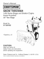 1
1
-
 2
2
-
 3
3
-
 4
4
-
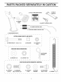 5
5
-
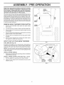 6
6
-
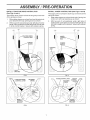 7
7
-
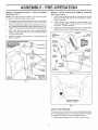 8
8
-
 9
9
-
 10
10
-
 11
11
-
 12
12
-
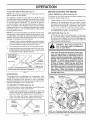 13
13
-
 14
14
-
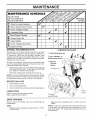 15
15
-
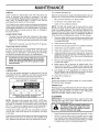 16
16
-
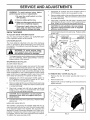 17
17
-
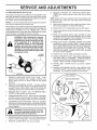 18
18
-
 19
19
-
 20
20
-
 21
21
-
 22
22
-
 23
23
-
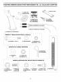 24
24
-
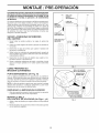 25
25
-
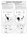 26
26
-
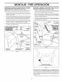 27
27
-
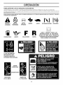 28
28
-
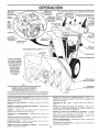 29
29
-
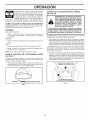 30
30
-
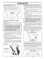 31
31
-
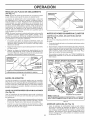 32
32
-
 33
33
-
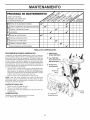 34
34
-
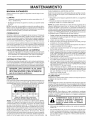 35
35
-
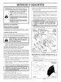 36
36
-
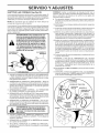 37
37
-
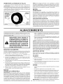 38
38
-
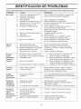 39
39
-
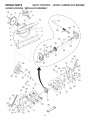 40
40
-
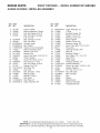 41
41
-
 42
42
-
 43
43
-
 44
44
-
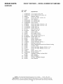 45
45
-
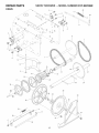 46
46
-
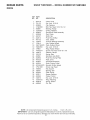 47
47
-
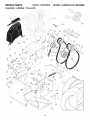 48
48
-
 49
49
-
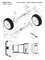 50
50
-
 51
51
-
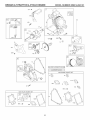 52
52
-
 53
53
-
 54
54
-
 55
55
-
 56
56
-
 57
57
-
 58
58
-
 59
59
-
 60
60


Craftsman 917881062 El manual del propietario
- Categoría
- Lanzadores de nieve
- Tipo
- El manual del propietario
en otros idiomas
- English: Craftsman 917881062 Owner's manual
Artículos relacionados
-
Craftsman 917881065 El manual del propietario
-
-
Craftsman 917881060 El manual del propietario
-
-
-
-
Otros documentos
-
Poulan 424027 Manual de usuario
-
-
Husqvarna 96193009702 El manual del propietario
-
-
-
Husqvarna ST 324 Manual de usuario
-
Kobalt A081002 Instrucciones de operación
-
 EarthWise SN70016 El manual del propietario
-
-
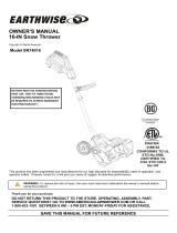 EarthWise SN74016 El manual del propietario

