MOTO GUZZI nevada Manual de usuario
- Categoría
- Motocicletas
- Tipo
- Manual de usuario
Este manual también es adecuado para
La página se está cargando...

Las instrucciones de este manual han sido preparadas principalmente para suministrar una guía simple y clara de uso; se indican también las
operaciones de mantenimiento básico y los controles periódicos que se deberán realizar en los CONCESIONARIOS o Talleres autorizados Moto
Guzzi. Además, el manual contiene las instrucciones para que pueda realizar algunas reparaciones simples. Las operaciones que no se describen
explícitamente en esta publicación requieren la disponibilidad de herramientas especiales y/o de conocimientos técnicos específicos. para su ejecución
recomendamos dirigirse a los CONCESIONARIOS o Talleres autorizados Moto Guzzi.
The instructions in this manual have been prepared to offer mainly a simple and clear guide to its use; it also describes routine maintenance procedures
and regular checks that should be carried out on the vehicle at an authorised Moto Guzzi Dealer or Workshop, The booklet also contains instructions
for simple repairs. Any operations not specifically described in this booklet require the use of special tools and/or particular technical knowledge; for
these operations, please take your vehicle to an authorised Moto Guzzi Dealer or Workshop.
2

Seguridad de las personas
El no-cumplimiento total o parcial de estas prescrip-
ciones puede comportar peligro grave para la incolu-
midad de las personas.
Personal safety
Failure to completely observe these instructions will
result in serious risk of personal injury.
Salvaguardia del ambiente
Indica el comportamiento correcto para que el uso del
vehículo no cause ningún daño a la naturaleza.
Safeguarding the environment
Sections marked with this symbol indicate the correct
use of the vehicle to prevent damaging the environ-
ment.
Integridad del vehículo
El no-cumplimiento total o parcial de estas prescrip-
ciones comporta el peligro de serios daños al vehículo
e incluso la caducidad de la garantía.
Vehicle intactness
The incomplete or non-observance of these regula-
tions leads to the risk of serious damage to the vehicle
and sometimes even the invalidity of the guarantee.
Las señales indicadas previamente son de gran im-
portancia. Sirven para evidenciar las partes del ma-
nual que requieren de más atención. Como se puede
observar, cada señal está compuesta por un símbolo
gráfico diferente, para facilitar y agilizar la búsqueda
de los temas en las diversas áreas. Antes de poner
en marcha el motor, leer atentamente este manual,
especialmente el apartado "CONDUCCIÓN SEGU-
RA". Su seguridad y la de los demás no depende
solamente de la rapidez de sus reflejos y agilidad, si-
no también del conocimiento del vehículo, de su efi-
ciencia y del conocimiento de las reglas fundamenta-
les para la CONDUCCIÓN SEGURA. Por lo tanto, le
recomendamos familiarizarse con el vehículo lo sufi-
ciente como para circular por la carretera con total
control y seguridad. IMPORTANTE Este manual se
debe considerar como parte integrante del vehículo y
debe acompañarlo en caso de venta.
The symbols illustrated above are very important.
They are used to highlight parts of the booklet that
should be read with particular care. The different sym-
bols are used to make each topic in the manual simple
and quick to locate. Before starting the engine, read
this booklet thoroughly and the "SAFE RIDING" sec-
tion in particular. Your safety as well as other's does
not only depend on the quickness of your reflexes and
agility, but also on how well you know your vehicle,
the state of maintenance of the vehicle itself and your
knowledge of the rules for SAFE RIDING. For your
safety, get to know your vehicle well so as to safely
ride and master it in road traffic IMPORTANT This
booklet is an integral part of the vehicle, and must be
handed to the new owner in the event of sale.
3
La página se está cargando...

INDICE
INDEX
NORMAS GENERALES................................................................. 9
Introducción.............................................................................. 10
Monóxido de carbono............................................................... 10
Combustible............................................................................. 11
Componentes calientes............................................................ 12
Puesta en marcha y Conducción............................................. 12
Testigos.................................................................................... 13
Aceite motor y aceite cambio usados...................................... 14
Líquido frenos y embrague...................................................... 15
Electrolito y gas hidrógeno de la batería.................................. 16
Soporte..................................................................................... 17
Comunicación de los defectos que influyen en la seguridad
................................................................................................. 18
VEHÌCULO...................................................................................... 19
Ubicación componentes principales............................................ 23
Tablero de instrumentos.............................................................. 25
Conjunto de instrumentos............................................................ 25
Grupo testigos............................................................................. 26
Reloj............................................................................................. 26
Representacion visual digital por cristales liquidos..................... 28
Simbolos de manutencion........................................................ 29
Regulacion cuentakilometros y parciales................................. 29
Regulacion muestra de la temperatura exterior....................... 31
Teclas de mando...................................................................... 32
Funciones avanzadas.............................................................. 33
Conmutador de encendido....................................................... 36
Bloqueo del volante.................................................................. 37
Pulsante claxon........................................................................... 38
Conmutador intermitentes........................................................... 39
Commutador luces....................................................................... 40
Pulsador ráfaga luz de carretera................................................. 41
GENERAL RULES............................................................................ 9
Foreword.................................................................................... 10
Carbon monoxide....................................................................... 10
Fuel............................................................................................ 11
Hot components......................................................................... 12
Start off and Riding..................................................................... 12
Warning lights............................................................................. 13
Used engine oil and gearbox oil................................................. 14
Brake and clutch fluid................................................................. 15
Battery hydrogen gas and electrolyte......................................... 16
Stand.......................................................................................... 17
Reporting of defects that affect safety........................................ 18
VEHICLE........................................................................................... 19
Arrangement of the main components........................................... 23
Dashboard..................................................................................... 25
Instrument panel............................................................................ 25
Light unit........................................................................................ 26
Clock.............................................................................................. 26
Digital lcd display........................................................................... 28
Maintenance icons..................................................................... 29
Setting the total and trip odometers........................................... 29
Setting the outside temperature display..................................... 31
Control buttons........................................................................... 32
Advanced functions.................................................................... 33
Ignition switch............................................................................. 36
Locking the steering wheel......................................................... 37
Horn button.................................................................................... 38
Switch direction indicators............................................................. 39
High/low beam selector.................................................................. 40
Passing button............................................................................... 41
Start-up button............................................................................... 41
5

Pulsante arranque....................................................................... 41
Interruptor parada motor.............................................................. 42
Mando del starter manual............................................................ 43
Abertura sillín........................................................................... 44
Compartimiento porta-doc./kit herramientas............................ 45
La identificación........................................................................... 45
EL USO........................................................................................... 47
Controles..................................................................................... 48
Abastecimiento............................................................................ 52
Regulación amortiguadores traseros........................................... 54
Regulación horquilla delantera.................................................... 56
Rodaje......................................................................................... 57
Arranque dificultoso..................................................................... 59
Aparcamiento............................................................................... 60
Escape catalítico.......................................................................... 61
Soporte........................................................................................ 63
Sugerencias contra los robos...................................................... 65
Normas basicás de seguridad..................................................... 67
EL MANTENIMIENTO.................................................................... 73
Premisa........................................................................................ 74
Control del nivel de aceite motor.............................................. 75
Llenado de aceite motor........................................................... 77
Sustitución aceite motor........................................................... 78
Nivel aceite cardán...................................................................... 82
Nivel aceite cambio...................................................................... 83
Neumáticos.................................................................................. 83
Desmontaje bujía......................................................................... 87
Desmontaje de los laterales........................................................ 92
Desmontaje filtro aire................................................................... 94
Control nivel aceite frenos........................................................... 95
Llenado liquido circuito de frenos............................................. 97
Puesta en servicio de una batería nueva................................. 97
Comprobacion del nivel del electrolito..................................... 99
Recarga batería....................................................................... 100
Larga inactividad.......................................................................... 101
Fusibles....................................................................................... 102
Bombillas..................................................................................... 104
Regulación proyector............................................................... 107
Indicadores de dirección delanteros............................................ 110
Engine stop switch......................................................................... 42
Manual starter control.................................................................... 43
Opening the saddle.................................................................... 44
Glove/tool kit compartment......................................................... 45
Identification................................................................................... 45
USE................................................................................................... 47
Checks........................................................................................... 48
Refuelling....................................................................................... 52
Rear shock absorbers adjustment................................................. 54
Front fork adjustment..................................................................... 56
Running in...................................................................................... 57
Difficult start up.............................................................................. 59
Parking........................................................................................... 60
Catalytic silencer............................................................................ 61
Stand.............................................................................................. 63
Suggestion to prevent theft............................................................ 65
Basic safety rules........................................................................... 67
MAINTENANCE................................................................................ 73
Foreword........................................................................................ 74
Engine oil level check................................................................. 75
Engine oil top-up........................................................................ 77
Engine oil change....................................................................... 78
Universal joint oil level................................................................... 82
Gearbox oil level............................................................................ 83
Tyres.............................................................................................. 83
Spark plug dismantlement............................................................. 87
Removing the sides....................................................................... 92
Removing the air filter.................................................................... 94
Checking the brake oil level........................................................... 95
Braking system fluid top up........................................................ 97
Use of a new battery.................................................................. 97
Checking the electrolyte level..................................................... 99
Charging the battery................................................................... 100
Long periods of inactivity............................................................... 101
Fuses............................................................................................. 102
Lamps............................................................................................ 104
Headlight adjustment.................................................................. 107
Front direction indicators................................................................ 110
Rear optical unit............................................................................. 111
6

Grupo óptico trasero.................................................................... 111
Indicadores de dirección traseros................................................ 112
Luz placa..................................................................................... 114
Espejos retrovisores.................................................................... 115
Freno de disco delantero y trasero.............................................. 117
Inactividad del vehiculo................................................................ 119
Limpieza del vehiculo.................................................................. 121
Transporte................................................................................... 125
DATOS TÉCNICOS........................................................................ 127
Herramientas en dotación............................................................ 136
EL MANTENIMIENTO PROGRAMADO......................................... 139
Tabla manutención programada.................................................. 140
PREPARACIONES ESPECIALES................................................. 147
Índice accesorios......................................................................... 148
Rear turn indicators........................................................................ 112
Number plate light.......................................................................... 114
Rear-view mirrors........................................................................... 115
Front and rear disc brake............................................................... 117
Periods of inactivity........................................................................ 119
Cleaning the vehicle....................................................................... 121
Transport........................................................................................ 125
TECHNICAL DATA........................................................................... 127
Kit equipment................................................................................. 136
PROGRAMMED MAINTENANCE.................................................... 139
Scheduled maintenance table........................................................ 140
SPECIAL FITTINGS.......................................................................... 147
Accessories index.......................................................................... 148
7
La página se está cargando...

Nevada - Nevada Anniversario
Cap. 01
Normas
generales
Chap. 01
General rules
9

Introducción
NOTA
EL TIEMPO PREVISTO PARA REALI-
ZAR LAS OPERACIONES DE MANTE-
NIMIENTO, DEBE SER REDUCIDO A
LA MITAD SI EL VEHÍCULO SE UTILI-
ZA EN ZONAS LLUVIOSAS, POLVO-
RIENTAS, EN RECORRIDOS ACCI-
DENTADOS O EN CONDUCCIÓN
DEPORTIVA.
Foreword
NOTE
CARRY OUT MAINTENANCE OPERA-
TIONS AT HALF THE INTERVALS
SPECIFIED IF THE VEHICLE IS USED
IN PARTICULAR RAINY OR DUSTY
CONDITIONS, OFF ROAD OR FOR
TRACK USE.
Monóxido de carbono
Si es necesario hacer funcionar el motor
para poder efectuar alguna operación,
asegurarse de que esto ocurra en un es-
pacio abierto o en un ambiente ventilado
de manera adecuada. Nunca hacer fun-
cionar el motor en espacios cerrados. Si
se trabaja en un espacio cerrado, utilizar
un sistema de evacuación de los humos
de escape.
ATENCIÓN
LOS HUMOS DE ESCAPE CONTIENEN
MONÓXIDO DE CARBONO, UN GAS
VENENOSO QUE PUEDE PROVOCAR
LA PÉRDIDA DE CONOCIMIENTO E
INCLUSO LA MUERTE.
Carbon monoxide
If you need to keep the engine running in
order to perform a procedure, please en-
sure that you do so in an open or very well
ventilated area. Never let the engine run
in an enclosed area. If you do work in an
enclosed area, make sure to use a
smoke-extraction system.
CAUTION
EXHAUST EMISSIONS CONTAIN
CARBON MONOXIDE, A POISONOUS
GAS WHICH CAN CAUSE LOSS OF
CONSCIOUSNESS AND EVEN
DEATH.
10
1 Normas generales / 1 General rules
La página se está cargando...

LA CAÍDA O LA EXCESIVA INCLINA-
CIÓN DEL VEHÍCULO PUEDEN PRO-
DUCIR DERRAMES DE COMBUSTI-
BLE.
VEHICLE FALL OR EXCESSIVE INCLI-
NATION CAN CAUSE FUEL OUT-
FLOW.
Componentes calientes
El motor y los componentes de la insta-
lación de escape alcanzan altas tempe-
raturas y permanecen calientes durante
un cierto período, incluso después de
apagar el motor. Para manipular estos
componentes, utilizar guantes aislantes
o esperar hasta que el motor y la insta-
lación de escape se hayan enfriado.
Hot components
The engine and the exhaust system com-
ponents get very hot and remain in this
condition for a certain time interval after
the engine has been switched off. Before
handling these components, make sure
that you are wearing insulating gloves or
wait until the engine and the exhaust sys-
tem have cooled down.
Puesta en marcha y
Conducción
ATENCIÓN
SI DURANTE LA CONDUCCIÓN, EN EL
TABLERO SE ENCIENDE EL TESTIGO
DE RESERVA DE COMBUSTIBLE,
SIGNIFICA QUE COMIENZA A UTILI-
ZARSE LA RESERVA.
REPONER COMBUSTIBLE LO ANTES
POSIBLE.
Start off and Riding
CAUTION
IF THE LOW FUEL WARNING LIGHT
ON THE INSTRUMENT PANEL TURNS
ON WHILE RIDING, THIS MEANS THE
RESERVE IS BEING USED.
REFUEL AS SOON AS POSSIBLE.
12
1 Normas generales / 1 General rules
La página se está cargando...
La página se está cargando...
La página se está cargando...
La página se está cargando...
La página se está cargando...

Comunicación de los defectos
que influyen en la seguridad
Salvo que se lo especifique en este Ma-
nual de Uso y Mantenimiento, no des-
montar ningún componente mecánico o
eléctrico.
ATENCIÓN
ALGUNOS CONECTORES DEL VEHÍ-
CULO PUEDEN INTERCAMBIARSE Y
SI SE MONTAN DE MANERA EQUIVO-
CADA PUEDEN PERJUDICAR EL
FUNCIONAMIENTO NORMAL DEL VE-
HÍCULO.
Reporting of defects that
affect safety
Unless otherwise specified in this Use
and Maintenance Booklet, do not remove
any mechanical or electrical component.
CAUTION
SOME CONNECTORS IN THE VEHI-
CLE MAY BE ACCIDENTALLY SWAP-
PED AND MAY COMPROMISE NOR-
MAL VEHICLE OPERATION IF INCOR-
RECTLY INSTALLED.
18
1 Normas generales / 1 General rules
La página se está cargando...
La página se está cargando...
La página se está cargando...
La página se está cargando...

02_04
Ubicación componentes
principales (02_04)
Leyenda:
1. Faro delantero
2. Espejo retrovisor izquierdo
3. Tapón del depósito de combus-
tible
4. Depósito combustible
5. Carenado lateral izquierdo
6. Portafusibles principales (30A)
7. Batería
8. Asiento conductor / pasajero
9. Asa de agarre pasajero
Arrangement of the main
components (02_04)
key:
1. Headlamp
2. Left rear-view mirror
3. Fuel tank cap
4. Fuel tank
5. Left side fairing
6. Main fuse box (30 A)
7. Battery
8. Rider/passenger saddle
9. Passenger grab handle
10. Rear left shock absorber
23
2 Vehìculo / 2 Vehicle

10. Amortiguador trasero izquierdo
11. Estribo izquierdo pasajero
12. Cerradura del asiento
13. Horquilla trasera
14. Caballete lateral
15. Estribo izquierdo del conductor
16. Palanca de mando del cambio
17. Varilla nivel de aceite del motor
18. Claxon izquierdo
19. Faro trasero
20. Depósito de líquido del freno
trasero
21. Portafusibles secundarios
22. Compartimiento portadocumen-
tos (sólo versión estándar)
23. Carenado lateral derecho
24. Espejo retrovisor derecho
25. Depósito líquido freno delantero
26. Filtro de aire
27. Claxon derecho
28. Filtro de aceite motor
29. Palanca de mando del freno tra-
sero
30. Estribo derecho conductor
31. Centralita electrónica (Magneti
Marelli IAW 15RC CA)
32. Bomba del freno trasero
33. Estribo derecho pasajero
34. Transmisión por árbol cardánico
35. Amortiguador trasero derecho
11. Passenger left footrest
12. Seat lock
13. Swingarm
14. Side stand
15. Left rider footrest
16. Gear shift lever
17. Engine oil level dipstick
18. Left horn
19. Taillight
20. Rear brake fluid reservoir
21. Auxiliary fuse box
22. Glove compartment (only stand-
ard version)
23. Right side fairing
24. Right rear-view mirror
25. Front brake fluid reservoir
26. Air filter
27. Right horn
28. Engine oil filter
29. Rear brake lever
30. Right rider footrest
31. Electronic control unit (Magneti
Marelli IAW 15RC CA)
32. Rear brake pump
33. Right passenger footrest
34. Cardan shaft transmission
35. Rear right shock absorber
24
2 Vehìculo / 2 Vehicle

02_05
02_06
Tablero de instrumentos
(02_05, 02_06)
Leyenda:
1. Palanca de mando embrague
2. Interruptor de arranque / blo-
queo del manillar
3. Instrumentos e indicadores
4. Palanca del freno delantero
5. Puño del acelerador
6. Pulsador destello luz de carre-
tera
7. Conmutador de luces
8. Palanca para el arranque en frío
9. Interruptor intermitentes
10. Pulsador claxon
11. Interruptor de parada del motor
12. Pulsador de arranque
Dashboard (02_05, 02_06)
Key:
1. Clutch control lever
2. Ignition switch /steering lock
3. Instruments and gauges
4. Front brake lever
5. Throttle grip
6. High-beam flashing switch
7. Light switch
8. Cold start lever
9. Turn indicator switch
10. Horn button
11. Engine stop switch
12. Starter button
02_07
Conjunto de instrumentos
(02_07)
Leyenda:
1. Velocímetro
2. Cuentarrevoluciones
3. Pantalla digital multifunción
Instrument panel (02_07)
Key:
1. Speedometer
2. Rpm indicator
3. Multifunctional digital display
25
2 Vehìculo / 2 Vehicle

02_08
Grupo testigos (02_08)
Leyenda:
1. Testigo intermitentes (color ver-
de)
2. Testigo luz de carretera (color
azul)
3. Testigo de presión de aceite
motor (color rojo)
4. Testigo reserva del combustible
(color amarillo ámbar)
5. Testigo 'EOBD' (color amarillo
ámbar)
6. Testigo cambio en punto muerto
(color verde)
Light unit (02_08)
Key:
1. Turn indicator warning light
(green)
2. High-beam warning light (blue)
3. Engine oil pressure warning
light (red)
4. Low fuel warning light (amber
yellow )
5. EOBD warning light (amber yel-
low)
6. Gear in neutral warning light
(green)
Reloj (02_09)
Regulación del reloj
•
Presionar durante dos segun-
dos consecutivos el botón (B).
•
Al activarse esta función el sím-
bolo AM parpadea.
•
Presionando el botón (A) se pa-
sa de AM a PM, con los símbo-
los parpadeantes.
•
Si se presiona el botón (B), se
pasa a la configuración de las
HORAS con el parpadeo de las
cifras correspondientes. Cada
vez que se presiona el botón (A)
el valor avanza 1 (de 0 a 11 y
vuelve a 0).
Clock (02_09)
Clock adjustment
•
Press key (B) for a couple of
seconds.
•
When this function is used, the
AM symbol starts flashing.
•
Press key (A) to change from
AM to PM, with the flashing sym-
bols.
•
Press key (B) to change to the
HOUR setting, and the specific
digits flash. Each time key (A) is
pressed, the value increases by
1 (from 0 to 11 and back to 0).
26
2 Vehìculo / 2 Vehicle

•
Si se presiona el botón (B), se
pasa a la configuración de los
MINUTOS con el parpadeo de
las cifras correspondientes.
•
Cada vez que se presiona el bo-
tón (A) el conteo avanza 1 (de 0
a 59 y vuelve a cero).
•
Si el botón (A) se mantiene pre-
sionado durante más de cinco
segundos: el valor aumenta 1
cada 100 ms.
•
Presionando una vez más el bo-
tón (B) se sale de la modalidad
de configuración para volver a la
función normal.
•
El reloj sólo se puede regular
con el vehículo detenido (velo-
cidad nula).
•
Press key (B) key to change to
the MINUTE setting, and the
specific digits flash.
•
Each time key (A) is pressed,
the counting advances by 1
(from 0 to 59 and back to zero).
•
Press and hold key (A) for more
than five seconds: the value in-
creases by 1 every 100ms.
•
Press key (B) again to exit the
setting mode and to go back to
standard operation.
•
The clock can be adjusted only
when the vehicle is at standstill
(zero speed).
02_09
Visualización del reloj
•
La visualización se distingue de
la regulación porque parpadean
los dos puntos centrales.
Secuencia visualizada:
- AM de 0.00 a 11.59
- PM de 12.00 a 11.59
Clock display
•
The display function is different
from the adjustment function in
that the central colon flashes.
Sequence displayed:
- AM from 0:00 to 11:59
- PM from 12:00 to 11:59
27
2 Vehìculo / 2 Vehicle

02_10
Representacion visual digital
por cristales liquidos (02_10)
•
Girando la llave de encendido a
la posición "ON", el sistema se
comporta del siguiente modo:
- activa simultáneamente todos los testi-
gos (lamp check);
- pone a cero la posición de las agujas,
que después realizan una carrera hasta
el fondo de escala y regresan nuevamen-
te a cero;
- activa durante un segundo todos los
segmentos de ambas pantallas;
- apaga todos los testigos (menos los que
están activados) y las pantallas vuelven
a la visualización normal.
Las programaciones estándar que se vi-
sualizan en la pantalla son:
- odómetro Total (Pantalla LCD izquier-
da) (1);
- temperatura aire (Pantalla LCD dere-
cha) (2).
Cualquiera sea el estado de las pantallas
antes del Key-Off.
Digital lcd display (02_10)
•
By turning the ignition key to
"ON", the system works as fol-
lows:
- it turns on all the warning lights at the
same time (lamp check);
- it resets the position of all the needles,
which afterwards go to the bottom of the
scale and return to zero;
- it activates all the segments of both dis-
plays for one second;
- it turns off all the warning lights (except
the active ones) and the displays go back
to standard view.
The standard indications displayed are:
- total odometer (left LCD Display) (1);
- air temperature (right LCD Display) (2).
no matter the status of the displays be-
fore Key-Off.
28
2 Vehìculo / 2 Vehicle

02_11
Simbolos de manutencion
(02_11)
•
El sistema visualiza la función
de la siguiente manera:
después de haber superado el kilometra-
je correspondiente al primer control pe-
riódico o a uno de los controles siguien-
tes, aparece la palabra "MAInt" en la
Pantalla LCD izquierda (1).
•
Esta visualización aparecerá
sólo después de cada arranque
y durante 5 segundos, luego se
pasará a la visualización nor-
mal.
•
Para la puesta a cero del Servi-
ce, dirigirse a un Concesionario
Oficial Moto Guzzi.
Maintenance icons (02_11)
•
The system displays the func-
tion as follows:
the word "MAInt" is shown on the left LCD
Display (1) after the mileage correspond-
ing to the first servicing or any subse-
quent servicing is exceeded.
•
This view is shown only after
each start-up for 5 seconds; af-
terwards, it will shift to the stand-
ard view.
•
Consult an Official Moto Guzzi
Dealer to reset Service.
02_12
Regulacion cuentakilometros
y parciales (02_12, 02_13)
Odómetro total
Unidad de medida para el conteo: Km o
Millas.
Visualización: en la pantalla LCD izquier-
da (1).
•
El dato se memoriza en forma
permanente.
•
No es posible volverlo a cero.
•
El odómetro total visualiza el da-
to del siguiente modo:
Setting the total and trip
odometers (02_12, 02_13)
Total odometer
Unit of measurement for the counter: Km
or Miles.
- View: on the left LCD display (1).
•
This value is stored permanent-
ly.
•
It cannot be reset.
•
Total odometer displays this val-
ue as follows:
- the TOTAL symbol is activated;
29
2 Vehìculo / 2 Vehicle

- se activa el símbolo TOTAL;
- si el valor supera 199999 se visualizan
en modo permanente "----".
- if the value exceeds 199999, the symbol
"----" is displayed permanently.
02_13
Odómetro parcial
Unidad de medida para el conteo: Km o
Millas.
Visualización: en la pantalla LCD izquier-
da (1).
•
El dato se memoriza.
•
Se puede volver a cero el con-
tador presionando durante dos
segundos consecutivos el botón
(A).
•
El odómetro parcial visualiza el
dato del siguiente modo:
- se activa el símbolo TRIP y el punto de-
cimal;
- si el valor supera 999.9 el contador se
pone a cero e inicia el conteo desde "0.0".
Trip odometer
Unit of measurement for the counter: Km
or Miles.
- View: on the left LCD display (1).
•
This value is stored.
•
Press and hold down key (A) for
two seconds to reset the coun-
ter.
•
Trip odometer displays the val-
ue as follows:
- the TRIP symbol and the decimal point
are activated;
- if the value exceeds 999.9, the counter
is reset and starts from "0.0" again.
30
2 Vehìculo / 2 Vehicle

02_14
Regulacion muestra de la
temperatura exterior (02_14)
Unidad de medida: °C o °F.
Visualización: en la pantalla LCD dere-
cha.
Los extremos de visualización son -10 /
+60 °C (14 / 140 °F).
•
Si la temperatura es inferior a
-10 °C (14 °F) en la pantalla LCD
derecha se visualizará la leyen-
da "LO" parpadeante.
•
Si el valor se encuentra entre
-10°C (14 °F) y +60°C (140 °F)
la pantalla visualizará el dato fi-
jo.
•
Si el valor es igual o superior a
+60°C (140 °F) la pantalla vi-
sualizará la leyenda "HI" parpa-
deante. Al mismo tiempo se
encenderá el símbolo de la uni-
dad de medida que se está
usando.
•
En el caso de que el sensor no
emitiera ninguna señal (corto
circuito o sensor desconectado)
se visualizarán tres líneas "---"
fijas.
Setting the outside
temperature display (02_14)
Unit of measurement: °C or °F.
- View: on the right LCD display.
The view limits are -10 / +60 °C (14 / 140
°F).
•
If temperature is below -10 °C
(14 °F), the word "LO" flashes
on the right LCD display.
•
If the value is between -10°C (14
°F) and +60°C (140 °F), it is
shown steadily on the display.
•
If the value is equivalent to or
higher than +60°C (140 °F), the
word "HI" flashes on the display.
The symbol signalling what unit
of measurement is being used
comes on at the same time.
•
If the sensor has no signal (short
circuit or disconnected), three
dashes "---" are shown steadily.
31
2 Vehìculo / 2 Vehicle

02_15
Teclas de mando (02_15)
•
Presionando el pulsador (A) con
la llave de encendido en la po-
sición "ON", en la pantalla LCD
izquierda (1) se alternan las si-
guientes visualizaciones:
- odómetro total (indica la distancia total
recorrida);
- odómetro parcial (indica la distancia re-
corrida desde la última puesta a cero o
bien desde que entra en reserva);
- Función TRIP / fuel (cuando el testigo
de reserva combustible está encendido
se visualiza la distancia recorrida en re-
serva);
•
Presionando el pulsador (B) con
la llave de encendido en la po-
sición "ON", en la Pantalla LCD
derecha (2) se alternan las si-
guientes visualizaciones:
- reloj;
- temperatura de aire.
Control buttons (02_15)
•
Push button (A) with the ignition
key set to "ON" and the following
views are shown alternately on
the left LCD Display (1):
- total odometer (shows the total distance
travelled);
- trip odometer (shows the distance trav-
elled since the last reset or use of re-
serve);
- TRIP / fuel function (when the low fuel
warning light turns on, the distance trav-
elled with reserve fuel is shown);
•
Push button (B) with the ignition
key set to "ON" and the following
views are shown alternately on
the right LCD Display (2):
- clock;
- air temperature.
32
2 Vehìculo / 2 Vehicle

02_16
Funciones avanzadas (02_16)
Función Trip Fuel
Esta función cuenta y visualiza el espacio
recorrido con el vehículo en reserva de
combustible.
Cuando se enciende el testigo de reser-
va:
•
en la pantalla LCD izquierda (1)
aparece automáticamente el to-
talizador del Trip Fuel;
•
presionando nuevamente el bo-
tón (A) es posible volver a la
visualización de Odómetro o
Trip y efectuar una visualización
cíclica de las tres magnitudes
Odómetro - Trip - Trip Fuel.
Si se posiciona la llave de encendido en
"ON":
•
durante los primeros sesenta
segundos (fase de estabiliza-
ción del sensor Reserva) el Trip
Fuel no se visualiza. Después
de lo cual el Trip Fuel se visua-
liza automáticamente. La moda-
lidad de visualización del Trip
Fuel es la siguiente:
- activa el símbolo TRIP y el punto, y en
el carácter más a la izquierda aparece la
letra "F";
- el valor inicial es "0.0".
Advanced functions (02_16)
Trip Fuel Function
This function counts and displays the dis-
tance travelled with the vehicle in fuel
reserve.
When the low fuel warning light turns on:
•
the Trip Fuel counter is automat-
ically shown on the left LCD dis-
play (1);
•
if key (A) is pressed again, the
Odometer or Trip can be viewed
again and scroll through the full
sequence of the three measure-
ments: Odometer - Trip - Trip
Fuel.
If the ignition key is set to "ON":
•
the Trip Fuel is not shown the
first sixty seconds (Reserve
sensor stabilisation phase).
Once this time is over, the Trip
Fuel is displayed automatically.
The Trip Fuel display mode is
the following:
- the TRIP symbol and point are activated
and the letter "F" is shown in the digit fur-
thermost on the left;
- the initial value is "0.0".
33
2 Vehìculo / 2 Vehicle

Función Alarma Fuel
Cuando el vehículo se encuentra en RE-
SERVA combustible:
•
en la pantalla LCD derecha (2)
aparece automáticamente la le-
yenda "FUEL" que se alterna
con la magnitud visualizada nor-
malmente (Reloj o temperatura
del aire)
•
La leyenda "FUEL" no se en-
ciende durante el arranque.
Fuel Alarm Function
When the vehicle is in fuel RESERVE:
•
the word "FUEL" is automatical-
ly shown on the right LCD dis-
play (2); it alternates with the
measurement generally dis-
played (Clock or air tempera-
ture)
•
The word "FUEL" does not
come on at start-up.
Función selección unidad
Esta función permite cambiar la unidad
de medida de la temperatura del aire (°C
o °F).
•
Si se posiciona la llave de en-
cendido en "ON" mantener pre-
sionados ambos botones (A y
B): en la pantalla LCD derecha
(2) se visualiza la configuración
actual "EU" (°C) o "USA" (°F)
parpadeante.
•
Presionando el botón (A): se pa-
sa de "EU" (°C) a "USA" (°F) y
viceversa.
•
Manteniendo presionado el bo-
tón (B) durante 5 segundos, se
memoriza en forma permanente
la última configuración y en la
pantalla LCD derecha (2) apa-
rece la leyenda "OFF".
Unit selection function
This function allows changing the unit of
measurement (°C or °F) for air tempera-
ture.
•
If the ignition key is set to "ON",
press and hold down both keys
(A and B): the current setting,
either "EU" (°C) or "USA" (°F),
flashes on the right LCD display
(2).
•
Press key (A): to shift from
"EU" (°C) to "USA" (°F) and vice
versa.
•
Press and hold down key (B) for
5 seconds and the last setting is
stored permanently and the
word "OFF" is shown on the
right LCD display (2).
•
To go back to the standard
mode, turn the ignition key to
"OFF".
34
2 Vehìculo / 2 Vehicle

•
Para volver a la modalidad nor-
mal se debe girar la llave de
encendido en "OFF".
Esta configuración no afecta a la unidad
de medida para Odómetro/Trip (Km o Mi-
llas).
This setting does not affect the unit of
measurement for the Odometer/Trip (Km
or Mile).
Regulación retroiluminación instru-
mentos
Es posible regular la retroiluminación de
los instrumentos (índices de las escalas
y pantalla) en tres niveles.
Este parámetro se puede regular dentro
de los cinco segundos después del
arranque. Cada vez que se presiona el
botón (B) se pasa al nivel inferior para
volver, en forma cíclica, al nivel máximo.
Al soltar el botón (B) durante dos segun-
dos se memoriza la selección y en el
siguiente arranque el sistema mantiene
el nivel de iluminación seleccionado.
Instrument backlighting adjustment
Backlighting of instruments and gauges
(needles of scales and displays) can be
adjusted at three levels.
This parameter can be adjusted within
five seconds after start-up. Every time
key (B) is pressed, it goes to the lower
level to return afterwards, in circular se-
quential mode, to the maximum level.
Once key (B) is released for two seconds,
the selection is stored and the next time
the vehicle is started, the system main-
tains the lighting level selected.
35
2 Vehìculo / 2 Vehicle

02_17
Conmutador de encendido
(02_17)
El interruptor de arranque se encuentra
en la placa superior del manguito de di-
rección.
Con el vehículo se entregan dos llaves
(una de reserva).
Las luces se apagan cuando el interrup-
tor de arranque está en «OFF»
NOTA
LA LLAVE ACCIONA EL CONMUTA-
DOR DE ARRANQUE/BLOQUEO DEL
MANILLAR, LA CERRADURA DEL TA-
PÓN DEL DEPÓSITO DEL COMBUSTI-
BLE Y LA CERRADURA DEL ASIENTO
NOTA
LAS LUCES SE ENCIENDEN AUTO-
MÁTICAMENTE AL ARRANCAR EL
MOTOR.
Ignition switch (02_17)
The ignition switch is located on the
headstock upper plate.
The vehicle is supplied with two keys
(one is the spare key).
The light switch turns off when the ignition
switch is set to «KEY OFF».
NOTE
THE KEY ACTIVATES THE IGNITION
SWITCH/ STEERING LOCK, THE FUEL
TANK CAP LOCK AND THE SADDLE
LOCK.
NOTE
THE LIGHTS TURN ON AUTOMATI-
CALLY UPON ENGINE START-UP.
36
2 Vehìculo / 2 Vehicle

NOTA
CONSERVAR LA LLAVE DE RESER-
VA EN UN LUGAR SEPARADO DEL
VEHÍCULO.
NOTE
KEEP THE SPARE KEY IN DIFFERENT
PLACE, NOT WITH THE VEHICLE.
02_18
Bloqueo del volante (02_18)
ATENCIÓN
NUNCA GIRAR LA LLAVE A LA POSI-
CIÓN «LOCK» DURANTE LA MAR-
CHA, PARA EVITAR LA PÉRDIDA DEL
CONTROL DEL VEHÍCULO.
Locking the steering wheel
(02_18)
CAUTION
AVOIDING LOSING CONTROL OF THE
VEHICLE - NEVER TURN THE KEY TO
«LOCK» WHILE RIDING.
Para bloquear la dirección:
•
Girar el manillar completamente
hacia la izquierda.
•
Girar la llave a la posición
«OFF».
•
Presionar y girar la llave en sen-
tido antihorario (hacia la izquier-
To lock the steering:
•
Turn the handlebar fully to the
left.
•
Turn the key to «OFF».
•
Press and turn the key anti-
clockwise (to the left), move the
37
2 Vehìculo / 2 Vehicle

da), girar lentamente el manillar
hasta posicionar la llave en
«LOCK».
•
Extraer la llave.
handlebar slowly until the key is
set to «LOCK».
•
Take out the key.
LOCK: La dirección está bloqueada. No
es posible poner en marcha el motor y
accionar las luces. Se puede sacar la lla-
ve
OFF: El motor y las luces no se pueden
poner en funcionamiento. Se puede sa-
car la llave.
ON: El motor puede ponerse en funcio-
namiento. No se puede sacar la llave
LOCK: The steering is locked. It is not
possible to start the engine or switch on
the lights. The key can be extracted
OFF: The engine and lights cannot be set
to work. The key may be removed.
ON: the engine may be started. The key
cannot be extracted.
Pulsante claxon (02_19)
NOTA
LOS COMPONENTES ELÉCTRICOS
FUNCIONAN SÓLO CON EL INTE-
RRUPTOR DE ARRANQUE EN POSI-
CIÓN «ON»
Horn button (02_19)
NOTE
ELECTRICAL COMPONENTS FUNC-
TION ONLY WHEN THE IGNITION KEY
IS SET TO "ON"
38
2 Vehìculo / 2 Vehicle

02_19
Presionado, pone en funcionamiento el
avisador sonoro.
Press it to activate the horn.
Conmutador intermitentes
(02_20)
NOTA
LOS COMPONENTES ELÉCTRICOS
FUNCIONAN SÓLO CON EL INTE-
RRUPTOR DE ARRANQUE EN POSI-
CIÓN «ON»
Switch direction indicators
(02_20)
NOTE
ELECTRICAL COMPONENTS FUNC-
TION ONLY WHEN THE IGNITION KEY
IS SET TO "ON"
02_20
Para girar hacia la izquierda, desplazar el
interruptor hacia la izquierda; para girar
hacia la derecha, desplazar el interruptor
hacia la derecha. Presionar el interruptor
para desactivar el intermitente.
ATENCIÓN
SI EL TESTIGO FLECHAS PARPADEA
RÁPIDAMENTE, SIGNIFICA QUE UNA
O AMBAS BOMBILLAS DE LOS IN-
TERMITENTES ESTÁN QUEMADAS.
Move the switch to the left, to indicate a
left turn; move the switch to the right to
indicate a right turn. Pressing the switch
deactivates the turn indicator.
CAUTION
IF THE WARNING LIGHT WITH AR-
ROWS FLASHES QUICKLY, IT MEANS
THAT ONE OR BOTH TURN INDICA-
TORS LIGHT BULBS ARE BURNT
OUT.
39
2 Vehìculo / 2 Vehicle

Commutador luces (02_21)
NOTA
LOS COMPONENTES ELÉCTRICOS
FUNCIONAN SÓLO CON EL INTE-
RRUPTOR DE ARRANQUE EN POSI-
CIÓN «ON»
High/low beam selector
(02_21)
NOTE
ELECTRICAL COMPONENTS FUNC-
TION ONLY WHEN THE IGNITION KEY
IS SET TO "ON"
02_21
Conmutador de luces
•
En la posición central, están
siempre activadas: la luz de po-
sición, la luz del tablero y la luz
de cruce.
•
En la posición izquierda, se ac-
tiva la luz de carretera.
•
En la posición derecha, se acti-
va el destello de la luz de carre-
tera, en caso de peligro o emer-
gencia.
Light switch
•
At central position, the tail light,
the instrument panel light and
the low-beam light are always
turned on.
•
Left position: the high-beam
light is turned on.
•
Right position: the high-beam
flash is turned on, in cases of
danger or emergency.
40
2 Vehìculo / 2 Vehicle

02_22
Pulsador ráfaga luz de
carretera (02_22)
NOTA
LOS COMPONENTES ELÉCTRICOS
FUNCIONAN SÓLO CON EL INTE-
RRUPTOR DE ARRANQUE EN POSI-
CIÓN «ON»
Passing button (02_22)
NOTE
ELECTRICAL COMPONENTS FUNC-
TION ONLY WHEN THE IGNITION KEY
IS SET TO "ON"
Permite utilizar el destello de la luz de
carretera en casos de peligro o emergen-
cia.
Al liberar el pulsador se desactiva el des-
tello de la luz de carretera.
Uses the high-beam flash in case of dan-
ger or emergency.
Releasing the switch deactivates the
high-beam flash.
02_23
Pulsante arranque (02_23)
NOTA
LOS COMPONENTES ELÉCTRICOS
FUNCIONAN SÓLO CON EL INTE-
RRUPTOR DE ARRANQUE EN POSI-
CIÓN «ON»
Start-up button (02_23)
NOTE
ELECTRICAL COMPONENTS FUNC-
TION ONLY WHEN THE IGNITION KEY
IS SET TO "ON"
Presionando el pulsador, el arrancador
pone en funcionamiento el motor.
Press the button and the starter motor
spins the engine.
41
2 Vehìculo / 2 Vehicle

02_24
Interruptor parada motor
(02_24)
ATENCIÓN
NO UTILIZAR EL INTERRUPTOR DE
PARADA DEL MOTOR DURANTE LA
MARCHA.
Engine stop switch (02_24)
CAUTION
DO NOT OPERATE THE ENGINE STOP
SWITCH WHILE RIDING THE VEHI-
CLE.
Cumple la función de interruptor de se-
guridad o de emergencia.
Presionando el interruptor en la posición
«KEY ON» se puede arrancar el motor;
presionándolo en la posición «KEY
OFF», el motor se detiene.
ATENCIÓN
CON EL MOTOR DETENIDO Y EL IN-
TERRUPTOR DE ARRANQUE EN PO-
It acts as an engine cut-off or emergency
stop switch.
When the switch is pressed in "KEY ON",
the engine can be started; when pressed
in " KEY OFF", the engine stops.
CAUTION
WITH ENGINE OFF AND THE IGNITION
SWITCH SET TO «ON» THE BATTERY
MAY GET DISCHARGED.
42
2 Vehìculo / 2 Vehicle

SICIÓN «ON» LA BATERÍA PODRÍA
DESCARGARSE.
CON EL VEHÍCULO DETENIDO Y DES-
PUÉS DE HABER PARADO EL MO-
TOR, COLOCAR EL INTERRUPTOR
DE ARRANQUE EN LA POSICIÓN
«OFF».
WITH THE VEHICLE AT A STAND-
STILL AND AFTER SHUTTING OFF
THE ENGINE, TURN THE IGNITION
SWITCH TO «OFF».
02_25
Mando del starter manual
(02_25)
Al girar hacia abajo la palanca para el
arranque en frío, entra en funcionamien-
to el starter para el mencionado arranque
del motor.
Para desactivar el starter, llevar la palan-
ca para el arranque en frío a la posición
inicial.
Manual starter control (02_25)
By turning the cold start lever down-
wards, the engine cold start starter be-
gins working.
To disconnect the starter, restore the cold
start lever to its initial position.
43
2 Vehìculo / 2 Vehicle

02_26
02_27
Abertura sillín (02_26, 02_27)
•
Colocar el vehículo sobre el ca-
ballete.
•
Introducir la llave (1) en la ce-
rradura del asiento.
•
Girar la llave (1) en sentido an-
tihorario, levantar y extraer el
asiento (2) por la parte poste-
rior.
ATENCIÓN
ANTES DE BAJAR Y BLOQUEAR EL
ASIENTO, CONTROLAR DE NO HA-
BER OLVIDADO LA LLAVE EN LOS
COMPARTIMIENTOS PORTADOCU-
MENTOS/KIT HERRAMIENTAS.
Opening the saddle (02_26,
02_27)
•
Rest the vehicle on its stand.
•
Insert the key (1) in the saddle
lock.
•
Turn the key (1) anticlockwise,
lift and remove the saddle (2) af-
terwards.
CAUTION
BEFORE LOWERING AND LOCKING
THE SADDLE, CHECK THAT THE KEY
HAS NOT BEEN LEFT INSIDE THE
GLOVE-BOX / TOOLKIT COMPART-
MENT.
Para bloquear el asiento:
•
Posicionar la parte delantera del
asiento en su alojamiento y ba-
jar la parte trasera.
•
Presionar en la parte trasera,
hasta que enganche la cerradu-
ra.
To lock the saddle:
•
Place the saddle front part in its
seat and lower the rear part.
•
Press the rear part to trip the
lock.
44
2 Vehìculo / 2 Vehicle

ANTES DE CONDUCIR ASEGURARSE
DE QUE EL ASIENTO ESTÉ CORREC-
TAMENTE BLOQUEADO.
BEFORE RIDING, MAKE SURE THAT
THE SADDLE IS CORRECTLY
LOCKED.
Compartimiento porta-doc./kit
herramientas
Para acceder al compartimiento portado-
cumentos / kit de herramientas, sacar el
asiento.
Glove/tool kit compartment
Remove the saddle to have access to the
glove-box / toolkit compartment.
02_28
La identificación (02_28,
02_29)
Es conveniente tomar nota de los núme-
ros del chasis y del motor, en el espacio
reservado para los mismos en el presen-
te manual. El número de chasis puede
ser útil para adquirir piezas de repuesto.
ATENCIÓN
LA MODIFICACIÓN DE LOS CÓDIGOS
DE IDENTIFICACIÓN CONSTITUYE
UN DELITO QUE PUEDE SANCIONAR-
SE CON GRAVES IMPUTACIONES
CRIMINALES. ADEMÁS, LA GARAN-
TÍA LIMITADA PARA NUEVOS VEHÍ-
Identification (02_28, 02_29)
Write down the chassis and engine num-
ber in the specific space in this booklet.
The chassis number is handy when pur-
chasing spare parts.
CAUTION
THE MODIFICATION OF THE IDENTI-
FICATION CODES IS A SERIOUS PUN-
ISHABLE CRIME. HOWEVER, THE
LIMITED WARRANTY FOR NEW VEHI-
CLES WILL BE VOID IF THE VEHICLE
IDENTIFICATION NUMBER (VIN) HAS
BEEN MODIFIED OR NOT PROMPTLY
DETERMINED.
45
2 Vehìculo / 2 Vehicle

CULOS QUEDARÁ SIN EFECTO SI SE
MODIFICA EL NÚMERO DE IDENTIFI-
CACIÓN DEL VEHÍCULO (VIN) O SI EL
MISMO NO PUEDE IDENTIFICARSE
RÁPIDAMENTE.
02_29
NÚMERO DE CHASIS
El número de chasis está estampillado
en el manguito de dirección, lado dere-
cho.
Chasis n....................
CHASSIS NUMBER
The chassis number is stamped on the
right hand side of the headstock.
Chassis No. ....................
NÚMERO DE MOTOR
El número del motor está estampillado en
la parte izquierda del vehículo cerca del
tapón de control del nivel de aceite motor.
Motor Nº....................
ENGINE NUMBER
The engine number is stamped on the left
side, close to the engine oil level check
cap.
Engine No. ....................
46
2 Vehìculo / 2 Vehicle

Nevada - Nevada Anniversario
Cap. 03
El uso
Chap. 03
Use
47
La página se está cargando...

03_01
Cada vez que se posiciona el interruptor
de arranque en 'KEY ON' se enciende el
testigo 'EOBD' durante aproximadamen-
te dos segundos.
Every time the ignition switch is set to
'KEY ON', the 'EOBD' warning light turns
on for about two seconds.
CONTROLES PRELIMINARES
Freno de disco delantero y trasero Controlar el funcionamiento, la
carrera en vacío de las palancas
de mando, el nivel del líquido y
eventuales pérdidas. Controlar el
desgaste de las pastillas. Si es
necesario efectuar el rellenado del
líquido de frenos.
Acelerador Controlar que funcione con
suavidad y que se pueda abrir y
cerrar completamente, en todas
las posiciones de la dirección.
Regular y/o lubricar si es
necesario.
Aceite motor Controlar y/o restaurar el nivel si es
necesario.
Ruedas/neumáticos Controlar el estado superficial de
los neumáticos, la presión de
PRE-RIDE CHECKS
Front and rear disc brake Check for proper operation. Check
brake lever empty travel and brake
fluid level. Check for leaks. Check
brake pads for wear. If necessary
top-up with brake fluid.
Throttle grip Check that the throttle functions
smoothly and can be fully opened
and closed in all steering positions.
Adjust and/or lubricate if
necessary.
Engine oil Check and/or top-up as required.
Wheels/ tyres Check that tyres are in good
conditions. Check inflation
pressure, tyre wear and potential
damage.
49
3 El uso / 3 Use

inflado, el desgaste y eventuales
daños.
Quitar eventuales cuerpos
extraños encastrados en las
esculturas de la banda de
rodadura.
Palancas del freno Controlar que funcionen con
suavidad.
Lubricar las articulaciones y
regular la carrera si es necesario.
Embrague Controlar el funcionamiento, la
carrera en vacío de la palanca de
mando, el nivel del líquido y
eventuales pérdidas. Si es
necesario, efectuar el llenado del
líquido: el embrague debe
funcionar sin tironeos ni
deslizamientos.
Dirección Controlar que la rotación sea
homogénea, fácilmente deslizable
y sin juego ni aflojamientos.
Caballete central - lateral Controlar que funcione. Controlar
que durante el descenso y el
ascenso del caballete no haya
fricciones y que la tensión de los
muelles lo regrese a su posición
normal. Lubricar los
acoplamientos y las articulaciones
si es necesario. Controlar el
correcto funcionamiento del
interruptor de seguridad.
Remove any possible strange
body that might be stuck in the
tread design.
Brake levers Check they function smoothly.
Lubricate the joints and adjust the
travel if necessary.
Clutch Check for proper operation. Check
clutch lever free play and fluid
level. Check for leaks. Top-up the
fluid if necessary; the clutch must
work without gripping and/or
sliding.
Steering Check that the rotation is uniform,
smooth and there are no signs of
clearance or slackness.
Centre - side stand Check it works properly. Check
that there is no resistance when the
side stand is pulled up and down
and that the spring tension makes
it snap back to its rest position.
Lubricate couplings and joints if
necessary. Check the safety
switch for correct operation.
Clamping elements Check that the clamping elements
are not loose.
Adjust or tighten them as required.
Fuel tank Check the coolant level and refill if
necessary.
50
3 El uso / 3 Use

Elementos de fijación Controlar que los elementos de
fijación no se estén flojos.
Eventualmente, regular o apretar.
Depósito combustible Controlar el nivel y reabastecer si
es necesario.
Controlar las eventuales pérdidas
u oclusiones del circuito.
Controlar que el tapón de
combustible esté correctamente
cerrado.
Interruptor de parada del motor
(ON - OFF)
Controlar el funcionamiento
correcto.
Luces, testigos, avisador acústico,
interruptores luz de stop trasera y
dispositivos eléctricos
Controlar el funcionamiento
correcto de los dispositivos
sonoros y visuales. Sustituir las
bombillas o intervenir en caso de
avería.
Aceite de transmisión - Guzzi Controlar. Si fuera necesario
realizar el llenado, dirigirse a un
taller autorizado Moto Guzzi.
Check the circuit for leaks or
obstructions.
Check that the tank cap closes
correctly.
Engine stop switch (ON - OFF) Check function.
Lights, warning lights, horn, rear
stop light switch and electrical
devices
Check function of horn and lights.
Replace bulbs or repair any faults
noted.
Transmission oil - Guzzi Check. Should top-up be
necessary, please refer to an
authorised Moto Guzzi repair
shop.
51
3 El uso / 3 Use

03_02
Abastecimiento (03_02)
Para reabastecer el combustible:
•
Introducir la llave (1) en la ce-
rradura del tapón del depósito
(2).
•
Rotar la llave en sentido antiho-
rario, tirar y extraer la tapa del
depósito (2).
NO AGREGAR ADITIVOS U OTRAS
SUSTANCIAS AL COMBUSTIBLE.
SI SE USA UN EMBUDO U OTRO OB-
JETO, ASEGURARSE DE QUE ESTÉ
PERFECTAMENTE LIMPIO.
NO LLENAR COMPLETAMENTE EL
DEPÓSITO; EL NIVEL MÁXIMO DE
COMBUSTIBLE DEBE PERMANECER
POR DEBAJO DEL BORDE INFERIOR
DEL COLECTOR (VER FIGURA).
Refuelling (03_02)
To refuel:
•
Introduce the key (1) in the fuel
tank cap lock (2).
•
Turn the key anticlockwise, pull
and remove the fuel tank cap
(2).
DO NOT ADD ADDITIVES OR ANY
OTHER SUBSTANCES TO THE FUEL.
WHEN USING A FUNNEL OR ANY
OTHER ELEMENT, MAKE SURE IT IS
PERFECTLY CLEAN.
DO NOT FILL THE TANK UP TO THE
RIM; FUEL MAXIMUM LEVEL MUST
ALWAYS BE BELOW THE LOWER
EDGE OF THE FILLER NECK (SEE
FIGURE).
Characteristic
Fuel (reserve included)
52
3 El uso / 3 Use

Características Técnicas
Combustible (incluido reserva)
14 l (3.70 gal US)
Reserva de combustible
4 l (1.056 gal US)
14 l (3.70 USgal)
Fuel reserve
4 l (1.056 US gal)
•
Reabastecer.
Al concluir el reabastecimiento:
ATENCIÓN
EL TAPÓN PUEDE CERRARSE SOLA-
MENTE CON LA LLAVE (1) INTRODU-
CIDA.
•
Refuel.
After refuelling:
CAUTION
THE CAP CAN ONLY BE CLOSED IF
THE KEY (1) IS INSERTED.
•
Con la llave (1) introducida, vol-
ver a cerrar el tapón, presionán-
dolo.
ASEGURARSE DE QUE LA TAPA ES-
TÉ CORRECTAMENTE CERRADA.
•
Once the key (1) is inserted,
press the cap to close it again.
MAKE SURE THE CAP IS TIGHTLY
CLOSED.
•
Retirar la llave (1).
•
Remove the key (1).
53
3 El uso / 3 Use

03_03
03_04
03_05
Regulación amortiguadores
traseros (03_03, 03_04, 03_05)
Para regular la configuración, el amorti-
guador cuenta con un regulador de tuer-
ca (1) para regular la precarga del muelle
(2) y con una tuerca de bloqueo (3).
NOTA
SE PUEDE REGULAR LA ALTURA DE
LA PARTE TRASERA DEL VEHÍCULO
PARA PERSONALIZAR EL AJUSTE
DEL MISMO.
Rear shock absorbers
adjustment (03_03, 03_04,
03_05)
To adjust setting, the shock absorber has
a ring nut set screw (1) to adjust preload-
ing of spring (2) and a locking ring nut (3).
NOTE
THE VEHICLE REAR HEIGHT CAN BE
ADJUSTED TO PERSONALISE THE
SUSPENSION SETTING.
54
3 El uso / 3 Use

NOTA
EL TIEMPO PREVISTO PARA REALI-
ZAR LAS OPERACIONES DE MANTE-
NIMIENTO, DEBE SER REDUCIDO A
LA MITAD SI EL VEHÍCULO SE UTILI-
ZA EN ZONAS LLUVIOSAS, POLVO-
RIENTAS, EN RECORRIDOS ACCI-
DENTADOS O EN CONDUCCIÓN
DEPORTIVA.
ATENCIÓN
NO FORZAR LA ROTACIÓN DEL RE-
GULADOR (1), MÁS ALLÁ DEL FINAL
DE CARRERA EN LOS DOS SENTI-
DOS, PARA EVITAR POSIBLES DA-
ÑOS.
NOTE
CARRY OUT MAINTENANCE OPERA-
TIONS AT HALF THE INTERVALS
SPECIFIED IF THE VEHICLE IS USED
IN PARTICULAR RAINY OR DUSTY
CONDITIONS, OFF ROAD OR FOR
TRACK USE.
CAUTION
TO AVOID DAMAGE, DO NOT FORCE
THE SET SCREW (1) BEYOND THE
RESPECTIVE END OF TRAVEL ON EI-
THER SIDE.
•
Utilizando la llave apropiada,
desenroscar la tuerca de blo-
queo (3).
•
Intervenir en la tuerca de regu-
lación (1) para regular la precar-
ga del muelle (A) utilizando la
correspondiente llave de espi-
gón que se encuentra en el so-
bre de las herramientas.
•
Enroscar para aumentar la pre-
carga; viceversa, desenroscar
para disminuirla.
•
Efectuada la regulación, apretar
la tuerca (3).
ATENCIÓN
PARA LOGRAR UNA BUENA ESTABI-
LIDAD DEL VEHÍCULO ES SIEMPRE
•
Using the specific spanner, un-
screw the locking ring nut (3).
•
Act on the adjustment ring nut
(1) to adjust the preloading of
spring (A) with the relevant hook
spanner included in the toolkit
pouch.
•
Screw to increase preloading;
and vice versa, screw to reduce
it.
•
Once the adjustment is done,
screw the ring nut (3).
CAUTION
TO OBTAIN A GOOD STABILITY IN
YOUR VEHICLE, MAKE SURE THAT
BOTH SHOCK ABSORBERS ARE AD-
JUSTED AT THE SAME POSITION. IF
55
3 El uso / 3 Use

CONVENIENTE ASEGURARSE DE
QUE AMBOS AMORTIGUADORES
HAYAN SIDO REGULADOS EN LA
MISMA POSICIÓN. SI FUERA NECE-
SARIO DIRIGIRSE A UN Concesiona-
rio Oficial Moto Guzzi.
NECESSARY, CONTACT AN Official
Moto Guzzi Dealer.
03_06
03_07
Regulación horquilla
delantera (03_06, 03_07)
Periódicamente, efectuar los siguientes
controles:
Con la palanca del freno delantero accio-
nada, presionar repetidamente en el ma-
nillar, empujando a fondo la horquilla. La
carrera debe ser suave y los vástagos no
deben evidenciar marcas de aceite.
Controlar el ajuste de todos los órganos
y el funcionamiento de las articulaciones
de la suspensión delantera y trasera.
ATENCIÓN
PARA CAMBIAR EL ACEITE DE LA
HORQUILLA DELANTERA Y LOS RE-
TENES DE ACEITE, DIRIGIRSE A UN
Concesionario Oficial Moto Guzzi.
Front fork adjustment (03_06,
03_07)
Carry out the following checks regularly:
Operating the front brake lever, press the
handlebar repeatedly to send the fork
fully down. The stroke should be soft and
there should be no oil marks on the
stems.
Check the tightening of all the elements
and the correct operation of the front and
rear suspension joints.
CAUTION
TO HAVE THE FRONT FORK OIL AND
OIL SEALS REPLACED, CONTACT AN
Official Moto Guzzi Dealer.
56
3 El uso / 3 Use

Rodaje
El rodaje del motor es fundamental para
garantizar su duración y su correcto fun-
cionamiento. Recorrer, en lo posible, ca-
rreteras con muchas curvas y/o con
colinas, donde el motor, las suspensio-
nes y los frenos sean sometidos a un
rodaje más eficaz. Variar la velocidad de
conducción durante el rodaje. De esta
manera, se permite "recargar" el trabajo
de los componentes y luego "aliviarlo",
enfriando las partes del motor.
ATENCIÓN
ES POSIBLE QUE DEL EMBRAGUE
SE DESPRENDA UN LEVE OLOR DE
QUEMADO, DURANTE EL PRIMER
PERIODO DE USO. ESTE FENÓMENO
ES PERFECTAMENTE NORMAL Y DE-
SAPARECERÁ APENAS LOS DISCOS
DEL EMBRAGUE TENGAN UN POCO
DE USO.
SI BIEN ES IMPORTANTE FORZAR
LOS COMPONENTES DEL MOTOR
DURANTE EL RODAJE, PRESTAR
MUCHA ATENCIÓN PARA NO EXCE-
DERSE.
ATENCIÓN
SÓLO DESPUÉS DE HABER EFEC-
TUADO EL CONTROL PERIÓDICO DE
FINALIZACIÓN DEL RODAJE ES PO-
SIBLE OBTENER LAS MEJORES
PRESTACIONES DEL VEHÍCULO.
Running in
Engine run-in is essential to ensure en-
gine long life and correct operation.
Twisty roads and gradients are ideal to
run in engine, brakes and suspensions
effectively. Vary your riding speed during
the run-in. This ensures that components
operate under both "loaded" and "unloa-
ded" conditions, allowing the engine
components to cool.
CAUTION
THE CLUTCH MAY EMIT A SLIGHT
BURNING SMELL WHEN FIRST USED.
THIS PHENOMENON SHOULD BE
CONSIDERED NORMAL AND WILL
DISAPPEAR AS SOON AS THE
CLUTCH DISCS GET ADAPTED.
IT IS IMPORTANT TO STRAIN ENGINE
COMPONENTS DURING RUN-IN,
HOWEVER, MAKE SURE NOT TO
OVERDO THIS.
CAUTION
THE FULL PERFORMANCE OF THE
VEHICLE IS ONLY AVAILABLE AFTER
THE SERVICE AT THE END OF THE
RUN-IN PERIOD.
57
3 El uso / 3 Use

Atenerse a las siguientes indicacio-
nes:
•
No acelerar repentina y comple-
tamente cuando el motor está
en marcha con un bajo régimen
de revoluciones, tanto durante
como después del rodaje.
•
Durante los primeros 100 km
(62 mi), accionar con prudencia
los frenos para evitar frenadas
bruscas y prolongadas. Esto
permite un correcto ajuste del
material de fricción de las pasti-
llas en los discos del freno.
AL ALCANZAR EL KILOMETRAJE
PREVISTO, DIRIGIRSE A UN CONCE-
SIONARIO OFICIAL Moto Guzzi PARA
QUE EJECUTE LOS CONTROLES
CONTEMPLADOS EN LA TABLA "FIN
DEL RODAJE" DE LA SECCIÓN MAN-
TENIMIENTO PROGRAMADO, CON
LA FINALIDAD DE EVITAR DAÑOS A
LAS PERSONAS O AL VEHÍCULO.
Follow the guidelines detailed below:
•
Do not twist the throttle grip
abruptly and completely when
the engine is working at a low
revs, either during or after run-
in.
•
During the first 100 Km (62
miles) use the brakes gently,
avoiding sudden or prolonged
braking. That is to permit the ad-
equate adjustment of the pad
friction material to the brake
discs.
AFTER THE SPECIFIED MILEAGE,
TAKE THE VEHICLE TO AN OFFICIAL
Moto Guzzi DEALER FOR THE
CHECKS INDICATED IN THE "AFTER
RUN-IN" TABLE IN THE SCHEDULED
MAINTENANCE SECTION TO AVOID
INJURING YOURSELF, OTHERS AND /
OR DAMAGING THE VEHICLE.
58
3 El uso / 3 Use

03_08
03_09
Arranque dificultoso (03_08,
03_09, 03_10)
ARRANQUE CON MOTOR AHOGADO
En caso de que el procedimiento de
arranque no se realice correctamente, o
cuando haya un exceso de combustible
en los conductos de aspiración, el motor
se podría ahogar.
Para limpiar un motor ahogado:
•
Presionar el pulsador de arran-
que (1) durante algunos segun-
dos (haciendo girar el motor en
vacío) con el puño del acelera-
dor (3) completamente girado
(pos. A).
Difficult start up (03_08, 03_09,
03_10)
START-UP WITH FLOODED ENGINE
The engine may get flooded if the start-
up procedure is not properly carried out
or there is excess fuel in the inlet ducts.
To clean a flooded engine:
•
Press the starter button (1) for a
few seconds (running the en-
gine with no gear engaged) with
the throttle grip (3) fully twisted
(Pos. A).
03_10
ARRANQUE EN FRÍO
En el caso de temperatura ambiente baja
(cercana o inferior a 0 °C) podrían verifi-
carse dificultades en el primer arranque.
En este caso:
•
Girar hacia abajo la palanca pa-
ra el arranque en frío (2).
•
Insistir durante al menos diez
segundos con el pulsador de
arranque accionado y, al mismo
COLD START
If the ambient temperature is low (near or
below 0°C), there may be problems with
the first start-up.
In this case:
•
Turn the cold start lever (2)
downwards.
•
Press the starter button for at
least ten seconds and at the
same time gradually turn the
throttle grip (3).
59
3 El uso / 3 Use

tiempo, girar con moderación el
puño del acelerador (3).
Si el motor arranca.
•
Soltar el puño del acelerador
(3).
•
Girar hacia arriba la palanca pa-
ra el arranque en frío (2).
En caso de que el ralentí sea inestable,
accionar el puño del acelerador (3) con
rotaciones pequeñas y frecuentes.
Si el motor no arranca.
•
Esperar algunos segundos e in-
tentar nuevamente el procedi-
miento de arranque.
If the engine starts.
•
Release the throttle grip (3).
•
Turn the cold start lever (2) up-
wards.
If idle speed is not stable, twist the throttle
grip (3) slightly and frequently.
If the engine does not start.
•
Wait for a few seconds and re-
peat the start-up procedure.
Aparcamiento
La elección de la zona de aparcamiento
es muy importante y se deben respetar la
señalización vial y las indicaciones que
se presentan a continuación.
ATENCIÓN
APARCAR EL VEHÍCULO SOBRE UN
TERRENO SÓLIDO Y PLANO PARA
EVITAR QUE SE CAIGA.
NO APOYAR EL VEHÍCULO EN LAS
PAREDES Y NO ACOSTARLO EN EL
PAVIMENTO.
ASEGURARSE DE QUE EL VEHÍCU-
LO, Y ESPECIALMENTE LAS PARTES
CALIENTES DEL MISMO, NO REPRE-
Parking
It is very important to select an adequate
parking spot, in compliance with road sig-
nals and the guidelines described below.
CAUTION
PARK ON SAFE AND LEVEL GROUND
TO PREVENT THE vehicle FROM
FALLING.
DO NOT LEAN THE vehicle ON A
WALL OR LAY IT ON THE GROUND.
MAKE SURE THE VEHICLE AND SPE-
CIALLY ITS HOT PARTS DO NOT
POSE ANY RISK TO PEOPLE OR
CHILDREN. DO NOT LEAVE YOUR VE-
HICLE UNATTENDED WITH THE EN-
60
3 El uso / 3 Use

SENTEN PELIGRO ALGUNO PARA
LAS PERSONAS Y LOS NIÑOS. NO
DEJAR EL VEHÍCULO SIN VIGILAN-
CIA, CON EL MOTOR ENCENDIDO O
CON LA LLAVE COLOCADA EN EL
CONMUTADOR DE ARRANQUE.
ATENCIÓN
LA CAÍDA O LA EXCESIVA INCLINA-
CIÓN DEL VEHÍCULO PUEDEN PRO-
DUCIR DERRAMES DE COMBUSTI-
BLE.
EL COMBUSTIBLE UTILIZADO PARA
LA PROPULSIÓN DE LOS MOTORES
DE EXPLOSIÓN ES EXTREMADA-
MENTE INFLAMABLE Y PUEDE RE-
SULTAR EXPLOSIVO EN DETERMI-
NADAS CONDICIONES.
NO CARGAR SOBRE EL CABALLETE
LATERAL EL PESO DEL CONDUC-
TOR NI EL DEL PASAJERO.
GINE ON OR THE KEY IN THE IGNI-
TION SWITCH.
CAUTION
VEHICLE FALL OR EXCESSIVE INCLI-
NATION CAN CAUSE FUEL OUT-
FLOW.
FUEL USED TO DRIVE EXPLOSION
ENGINES IS HIGHLY FLAMMABLE
AND CAN BECOME EXPLOSIVE UN-
DER SPECIFIC CONDITIONS.
DO NOT REST THE RIDER OR PAS-
SENGER WEIGHT ON THE SIDE
STAND.
Escape catalítico
El vehículo cuenta con un silenciador con
catalizador metálico del tipo "trivalente al
platino - paladio - rodio".
Este dispositivo tiene la tarea de oxidar
el CO (monóxido de carbono) convirtién-
dolo en anhídrido carbónico, los HC (hi-
Catalytic silencer
The vehicle has a silencer with a "plati-
num - palladium - rhodium three-way"
metal catalytic converter.
This device oxidises the CO (carbon
monoxide) producing carbon dioxide,
and the UHC (unburned hydrocarbons)
61
3 El uso / 3 Use

drocarburos sin quemar) convirtiéndolos
en vapor de agua y de reducir los NOX
(óxidos de nitrógeno) convirtiéndolos en
oxígeno y nitrógeno presentes en los ga-
ses de escape.
EVITAR DE APARCAR EL VEHÍCULO
CERCA DE ARBUSTOS SECOS O EN
LUGARES ACCESIBLES PARA LOS
NIÑOS DADO QUE EL SILENCIADOR
DEL ESCAPE, DURANTE EL USO, AL-
CANZA TEMPERATURAS MUY ELE-
VADAS; POR LO TANTO PRESTAR LA
MÁXIMA ATENCIÓN Y EVITAR TODO
TIPO DE CONTACTO ANTES DE QUE
SE HAYA ENFRIADO COMPLETA-
MENTE.
NO UTILIZAR GASOLINA CON PLO-
MO DADO QUE PROVOCA LA DES-
TRUCCIÓN DEL CATALIZADOR.
producing water vapour and reduces
NOX (nitrogen oxide) producing oxygen
and nitrogen present in the exhaust
fumes.
DO NOT PARK THE VEHICLE NEAR
DRY BRUSHWOOD OR IN PLACES
EASILY ACCESSIBLE BY CHILDREN
BECAUSE THE CATALYTIC CON-
VERTER REACHES HIGH TEMPERA-
TURES DURING VEHICLE OPERA-
TION; FOR THIS REASON, PAY
UTMOST ATTENTION AND DO NOT
TOUCH IT UNTIL IT HAS COMPLETE-
LY COOLED DOWN.
DO NOT USE LEADED PETROL AS IT
CAUSES IRREPARABLE DAMAGE TO
THE CATALYTIC CONVERTER.
Se advierte al propietario del vehículo
que la ley puede prohibir lo siguiente:
•
la eliminación de cualquier dis-
positivo o elemento incorporado
a un vehículo nuevo, con el fin
de controlar la emisión de rui-
dos, antes de la venta o entrega
del vehículo al comprador final o
mientras se lo está utilizando, o
cualquier otro acto tendiente a
inutilizarlo, por parte de cual-
quiera, salvo por intervenciones
Vehicle owners are warned that the law
may prohibit the following:
•
the removal of any device or el-
ement belonging to a new vehi-
cle or any other action by any-
one leading to render it non-
operating, if not for mainte-
nance, repair or replacement
reasons, in order to control
noise emission before the sale
or delivery of the vehicle to the
ultimate buyer or while it is used;
62
3 El uso / 3 Use

de mantenimiento, reparación o
sustitución;
•
el uso del vehículo después de
que dicho dispositivo o elemen-
to constitutivo haya sido extraí-
do o inutilizado.
Controlar el silenciador/tubo de escape y
los tubos del escape, comprobando que
no existan indicios de herrumbre u orifi-
cios y que el sistema de escape funcione
correctamente.
Si el ruido producido por el sistema de
escape aumenta, contactar inmediata-
mente con un CONCESIONARIO o un
Taller autorizado Moto Guzzi.
NOTA
ESTÁ PROHIBIDO ALTERAR EL SIS-
TEMA DE ESCAPE.
•
using the vehicle after that de-
vice or element has been re-
moved or rendered non-operat-
ing.
Check the muffler/exhaust silencer and
the silencer pipes, make sure there are
no signs of rust or holes and that the ex-
haust system works properly.
If the noise produced by the exhaust sys-
tem increases, get immediately in touch
with the Dealer or with a Moto Guzzi au-
thorised repair shop.
NOTE
DO NOT TAMPER WITH THE EX-
HAUST SYSTEM.
03_11
Soporte (03_11, 03_12, 03_13)
EL CABALLETE LATERAL Y EL CEN-
TRAL (SI LO HAY) DEBEN GIRAR LI-
BREMENTE: ENGRASAR LA ARTICU-
LACIÓN SI ES NECESARIO.
Stand (03_11, 03_12, 03_13)
THE SIDE STAND AND THE CENTRE
STAND (IF INSTALLED) MUST MOVE
SMOOTHLY; GREASE THE JOINT, IF
NECESSARY.
63
3 El uso / 3 Use

03_12
03_13
CABALLETE LATERAL
En el caso de que alguna maniobra (por
ejemplo: el desplazamiento del vehículo)
haya provocado el retroceso del caballe-
te,se debe proceder como se indica a
continuación para volver a poner el vehí-
culo sobre el mismo:
•
Tomar el puño izquierdo y apo-
yar la mano derecha sobre la
parte trasera superior del vehí-
culo.
•
Empujar el caballete lateral con
el pie derecho, extendiéndolo
completamente.
•
Inclinar el vehículo hasta que el
caballete se apoye en el suelo.
Girar el manillar completamente
hacia la izquierda
•
.
ATENCIÓN
ASEGURARSE DE LA ESTABILIDAD
DEL VEHÍCULO.
SIDE STAND
If the stand has been folded up for any
manoeuvre (for example, when the vehi-
cle is in motion), place the vehicle on the
stand again as follows:
•
Grasp the left grip and place
your right hand on the rear up-
per part of the vehicle.
•
Push on the side stand with your
right foot and lower it complete-
ly.
•
Lean the vehicle until the stand
is resting on the ground.
•
Turn the handlebar fully to the
left.
CAUTION
MAKE SURE THE VEHICLE IS STA-
BLE.
64
3 El uso / 3 Use

En el caballete lateral (1) se encuentra un
interruptor de seguridad (2) que tiene la
función de impedir o interrumpir el fun-
cionamiento del motor con la marcha
acoplada y el caballete lateral (1) bajo.
A safety switch (2) is installed on the side
stand (1) to inhibit ignition or to stop the
engine when a gear is engaged and the
side stand (1) is lowered.
Sugerencias contra los robos
ATENCIÓN
SI SE UTILIZA UN DISPOSITIVO DE
BLOQUEO DE DISCO, RECORDAR
MUY ESPECIALMENTE RETIRARLO
ANTES DE CONDUCIR EL VEHÍCULO.
LA INOBSERVANCIA DE ESTA AD-
VERTENCIA PODRÍA CAUSAR SE-
RIOS DAÑOS A LA INSTALACIÓN DE
FRENOS Y PROVOCAR ACCIDENTES
CON LOS CONSIGUIENTES DAÑOS
FÍSICOS O LA MUERTE
Suggestion to prevent theft
CAUTION
WHEN USING A DISC LOCKING DE-
VICE, PAY UTMOST ATTENTION TO
REMOVE IT BEFORE RIDING. FAIL-
URE TO OBSERVE THIS WARNING
MAY CAUSE SERIOUS DAMAGE TO
THE BRAKING SYSTEM AND ACCI-
DENTS WITH CONSEQUENT PHYSI-
CAL INJURIES OR EVEN DEATH.
NUNCA dejar la llave de contacto colo-
cada y siempre bloquear el manillar.
Aparcar el vehículo en un lugar seguro,
en lo posible en un garaje o en un lugar
con vigilancia. Siempre que sea posible,
utilizar un segundo dispositivo antirrobo.
Controlar que los documentos y el im-
puesto de circulación estén en orden. Es-
cribir los datos personales y el número de
teléfono en esta página para facilitar la
identificación del propietario, en caso de
NEVER leave the ignition key in the lock
and always use the steering lock. Park
the vehicle in a safe place such as a ga-
rage or a place with guards. Whenever
possible, use an additional anti-theft de-
vice. Make sure all vehicle documents
are in order and the road tax paid. Write
down your personal details and tele-
phone number on this page to help iden-
tifying the owner in case of vehicle
retrieval after a theft.
LAST NAME: ..................................
65
3 El uso / 3 Use

que se encuentre el vehículo, después
de un robo.
APELLIDO: ....................................
NOMBRE: .........................................
DIRECCIÓN: ....................................
N° TELEFÓNICO: ..........................
ADVERTENCIA
EN MUCHOS CASOS LOS VEHÍCU-
LOS ROBADOS SE IDENTIFICAN
GRACIAS A LOS DATOS INDICADOS
EN EL MANUAL DE USO Y MANTENI-
MIENTO.
NAME: .........................................
ADDRESS: .................................
TELEPHONE No: ..........................
WARNING
IN MANY CASES, STOLEN VEHICLES
CAN BE IDENTIFIED BY DATA IN THE
USE / MAINTENANCE BOOKLET
03_14
66
3 El uso / 3 Use

03_15
03_16
03_17
Normas basicás de seguridad
(03_15)
Prestar la máxima atención a las indica-
ciones siguientes porque fueron redacta-
das para evitar daños a las personas, a
las cosas o al vehículo, derivados de una
posible caída del piloto o del pasajero, o
de la caída o vuelco del vehículo.
Las operaciones de ascenso y descenso
del vehículo deben ser efectuadas con
total libertad de movimiento y con las ma-
nos libres (de objetos, casco, guantes o
antiparras, aún no utilizados).
Ascender y descender sólo por el lado
izquierdo del vehículo y sólo con el ca-
ballete lateral bajo.
Basic safety rules (03_15)
Follow the instructions given below atten-
tively to avoid injuring persons, damaging
property or the vehicle in the event of the
rider or the passenger falling off the ve-
hicle and/or the vehicle falling or over-
turning.
When getting on and off the vehicle,
make sure nothing is restricting your
movements; do not hold any objects in
your hands (helmet, gloves or goggles
not put on).
Always get on and off the vehicle on the
left side and with the side stand lowered.
67
3 El uso / 3 Use

03_18
El caballete fue proyectado para soste-
ner el peso del vehículo y un mínimo de
carga, sin conductor ni pasajero.
El ascenso en posición de conducción,
con el vehículo posicionado sobre el ca-
ballete lateral, sólo está permitido para
prevenir una posible caída o vuelco y no
prevé la carga del peso del conductor y/
o del pasajero.
Durante el ascenso y el descenso, el pe-
so del vehículo puede ocasionar un des-
balanceo con la consiguiente pérdida de
equilibrio y la posibilidad de una caída o
vuelco.
ATENCIÓN
EL CONDUCTOR ES SIEMPRE EL PRI-
MERO QUE ASCIENDE AL VEHÍCULO
Y EL ULTIMO EN DESCENDER Y ES
EL QUE GOBIERNA EL EQUILIBRIO Y
LA ESTABILIDAD DURANTE EL AS-
CENSO O DESCENSO DEL PASAJE-
RO
The stand has been designed to support
the weight of the vehicle and a minimum
load, without the added weight of rider
and passenger.
The purpose of the side stand is to pre-
vent the vehicle from falling or overturn-
ing while rider and passenger get on the
vehicle and get ready to ride; the stand
should not be used to support the weight
of rider and passenger.
While getting on and off, the vehicle may
become unstable due to its weight and it
may fall or overturn.
CAUTION
THE RIDER MUST GET ON THE VEHI-
CLE FIRST AND GET OFF LAST TO BE
ABLE TO CONTROL AND BALANCE
THE VEHICLE WHILE THE PASSEN-
GER IS GETTING ON OR OFF THE VE-
HICLE.
Por otra parte, el pasajero debe ascender
y descender del vehículo con cautela,
para no desbalancear el vehículo y el
conductor.
ATENCIÓN
ES TAREA DEL CONDUCTOR INS-
TRUIR AL PASAJERO ACERCA DE LA
When getting on and off the vehicle, the
passenger must move carefully so as not
to cause a loss of stability for vehicle and
rider.
CAUTION
THE RIDER MUST INSTRUCT THE
PASSENGER ON HOW TO GET ON
AND OFF THE VEHICLE SAFELY.
68
3 El uso / 3 Use
La página se está cargando...

cargar el propio peso en el ca-
ballete lateral.
ATENCIÓN
SI NO LOGRARA APOYAR AMBOS
PIES EN EL PISO, APOYAR EL DERE-
CHO (EN EL CASO DE DESBALAN-
CEO EL LADO IZQUIERDO ESTÁ
"PROTEGIDO" POR EL CABALLETE
LATERAL) Y MANTENER EL IZQUIER-
DO LISTO PARA APOYARSE.
ing your weight on the side
stand
CAUTION
IF YOU CAN NOT REACH THE
GROUND WITH BOTH FEET WHEN
SEATED, PLACE YOUR RIGHT FOOT
ON THE GROUND (IF YOU LOSE BAL-
ANCE, THE SIDE STAND WILL PRE-
VENT A FALL ON THE LEFT SIDE)
AND BE READY TO PUT YOUR LEFT
FOOT ON THE GROUND.
•
Apoyar ambos pies en tierra y
enderezar el vehículo en posi-
ción de marcha, manteniéndolo
en equilibrio.
ATENCIÓN
EL CONDUCTOR NO DEBE EXTRAER
O INTENTAR EXTRAER LOS ESTRI-
BOS REPOSAPIÉS DEL PASAJERO
DESDE LA POSICIÓN DE CONDUC-
CIÓN, PODRÍA COMPROMETER EL
EQUILIBRIO Y LA ESTABILIDAD DEL
VEHÍCULO.
•
Place both feet on the ground,
straighten and balance the ve-
hicle keeping it upright in riding
position.
CAUTION
THE RIDER MUST NOT EXTRACT OR
ATTEMPT TO EXTRACT THE PAS-
SENGER FOOTRESTS WHILE SEAT-
ED, BECAUSE THIS MIGHT COMPRO-
MISE VEHICLE STABILITY AND
BALANCE.
•
Hacer que el pasajero extraiga
los dos estribos reposapiés pa-
sajero.
•
Instruirlo acerca del ascenso al
vehículo.
•
Have the passenger fold out the
two passenger footrests.
•
Give instructions as necessary
to help the passenger mount the
vehicle.
•
Lift and retract the side stand
completely with the left foot.
GETTING OFF THE VEHICLE
70
3 El uso / 3 Use

•
Intervenir con el pie izquierdo en
el caballete lateral y hacer que
retorne completamente.
DESCENSO
•
Elegir la zona de aparcamiento.
•
Detener el vehículo.
ASEGURARSE DE QUE EL TERRENO
EN EL QUE SE HA APARCADO LA
MOTOCICLETA SEA ESTABLE, RE-
GULAR Y CARENTE DE OBSTÁCU-
LOS.
•
Select an appropriate parking
spot.
•
Stop the vehicle.
MAKE SURE THAT THE GROUND ON
WHICH THE MOTORCYCLE IS
PARKED IS STABLE, EVEN AND FREE
OF OBSTACLES.
•
Con el taco del pie izquierdo,
accionar en el caballete lateral y
extenderlo completamente.
ATENCIÓN
SI NO LOGRARA APOYAR AMBOS
PIES EN EL PISO, APOYAR EL DERE-
CHO (EN EL CASO DE DESBALAN-
CEO EL LADO IZQUIERDO ESTÁ
"PROTEGIDO" POR EL CABALLETE
LATERAL) Y MANTENER EL IZQUIER-
DO LISTO PARA APOYARSE.
•
With the left shoe heel, lower
and extend the side stand com-
pletely.
CAUTION
IF YOU CAN NOT REACH THE
GROUND WITH BOTH FEET WHEN
SEATED, PLACE YOUR RIGHT FOOT
ON THE GROUND (IF YOU LOSE BAL-
ANCE, THE SIDE STAND WILL PRE-
VENT A FALL ON THE LEFT SIDE)
AND BE READY TO PUT YOUR LEFT
FOOT ON THE GROUND.
•
Apoyar ambos pies en el piso y
mantener en equilibrio el vehí-
culo en posición de marcha.
•
Place both feet on the ground
and keep the vehicle balanced
in the upright position.
71
3 El uso / 3 Use

•
Instruir al pasajero acerca de la
forma correcta de descender del
vehículo.
PELIGRO DE CAÍDA O VUELCO.
ASEGURARSE DE QUE EL PASAJE-
RO HAYA DESCENDIDO DEL VEHÍCU-
LO. NO CARGAR EL PROPIO PESO
EN EL CABALLETE LATERAL
.
•
Give instructions as necessary
to help the passenger dismount
the vehicle.
RISK OF FALLING AND OVERTURN-
ING.
MAKE SURE THE PASSENGER HAS
GOT OFF THE VEHICLE.
DO NOT REST YOUR WEIGHT ON THE
SIDE STAND.
•
Inclinar la motocicleta hasta que
el caballete toque el suelo.
•
Empuñar correctamente el ma-
nillar y descender del vehículo.
•
Girar el manillar completamente
hacia la izquierda.
•
Colocar el reposapiés del pasa-
jero en posición.
ATENCIÓN
ASEGURARSE DE LA ESTABILIDAD
DEL VEHÍCULO.
•
Tilt the motorcycle until the
stand touch the ground.
•
Grasp the handlebar firmly and
get off the vehicle.
•
Turn the handlebar fully left-
wards.
•
Return the passenger footrests
to position.
CAUTION
MAKE SURE THE VEHICLE IS STA-
BLE.
72
3 El uso / 3 Use

Nevada - Nevada Anniversario
Cap. 04
El
mantenimiento
Chap. 04
Maintenance
73

Premisa
Normalmente las operaciones de mante-
nimiento ordinario pueden ser realizadas
por el usuario y a veces pueden necesitar
de la utilización de utillaje específico y de
una cierta preparación técnica. En caso
de mantenimiento periódico, interven-
ción de asistencia o de consulta técnica,
dirigirse a un CONCESIONARIO OFI-
CIAL Moto Guzzi, en donde se le garan-
tiza un servicio esmerado y rápido.
ADVERTENCIA
ESTE VEHÍCULO ESTA PREPARADO
PARA IDENTIFICAR EN TIEMPO
REAL, EVENTUALES ANOMALÍAS DE
FUNCIONAMIENTO, MEMORIZADAS
POR LA CENTRALITA ELECTRÓNI-
CA.
CADA VEZ QUE EL CONMUTADOR DE
ARRANQUE SE POSICIONA EN "ON",
EN EL TABLERO SE ENCIENDE, DU-
RANTE APROXIMADAMENTE TRES
SEGUNDOS, EL TESTIGO LED
"ALARMA".
Foreword
In general terms, scheduled mainte-
nance can be carried out by the owner;
however, some operations may require
specific tools and technical training. For
periodic maintenance, servicing or tech-
nical advice, contact an Official Moto
Guzzi Dealer for prompt and accurate
service.
WARNING
THIS VEHICLE HAS BEEN PROGRAM-
MED TO INDICATE IN REAL TIME ANY
ACTIVATION FAILURE STORED IN
THE ELECTRONIC CONTROL UNIT
MEMORY.
ANY TIME THE IGNITION SWITCH IS
SET TO "ON", THE "ALARMS" WARN-
ING LIGHT ON THE INSTRUMENT
PANEL TURNS ON FOR THREE SEC-
ONDS.
74
4 El mantenimiento / 4 Maintenance
La página se está cargando...

ALARMA Y EL ICONO DE PRESIÓN
ACEITE DEL MOTOR.
ATENCIÓN
PARA CALENTAR EL MOTOR Y LLE-
VAR EL ACEITE A TEMPERATURA DE
FUNCIONAMIENTO, NO HACER FUN-
CIONAR EL MOTOR EN RALENTÍ CON
EL VEHÍCULO DETENIDO.
EL PROCEDIMIENTO CORRECTO
PREVÉ EFECTUAR EL CONTROL
DESPUÉS DE UN VIAJE O DESPUÉS
DE HABER RECORRIDO APROXIMA-
DAMENTE 15 Km (10 mi) FUERA DE
LA CIUDAD (SUFICIENTES PARA
ELEVAR LA TEMPERATURA DEL
ACEITE DEL MOTOR).
CAUTION
DO NOT IDLE THE ENGINE WITH THE
VEHICLE AT A STANDSTILL TO
WARM THE ENGINE AND BRING THE
OIL TO OPERATING TEMPERATURE.
PREFERABLY CHECK THE OIL AF-
TER A JOURNEY OF AFTER TRAVEL-
LING APPROXIMATELY 15 Km (10
miles) IN EXTRAURBAN CONDITIONS
(ENOUGH TO WARM UP THE ENGINE
OIL TO OPERATING TEMPERATURE).
•
Parar el motor.
•
Mantener el vehículo en posi-
ción vertical con las dos ruedas
apoyadas en el piso.
•
Desenroscar el tapón de llena-
do / la varilla de nivel del aceite.
•
Comprobar a través de la varilla
el nivel de aceite.
'MÁX ' = nivel máximo.
'MÍN' = nivel mínimo.
La diferencia entre "MÁX" y "MÍN" es de
aproximadamente 400 cc (24.40 cu in).
•
Shut off the engine.
•
Keep the vehicle upright with
both wheels on the ground.
•
Unscrew the filler plug / oil dip-
stick.
•
Check oil level by means of the
oil dipstick.
'MAX' = maximum level.
'MIN' = minimum level.
The difference between 'MAX' and 'MIN'
marks is approx. 400 cm³ (24.40 cu.in).
•
The oil level is correct when it is
close to the 'MAX' mark.
76
4 El mantenimiento / 4 Maintenance

•
El nivel es correcto, si alcanza
aproximadamente el nivel
"MÁX".
ATENCIÓN
NO SOBREPASAR LA MARCA "MÁX"
NI DESCENDER POR DEBAJO DE LA
MARCA "MÍN", PARA EVITAR GRA-
VES DAÑOS AL MOTOR.
CAUTION
DO NOT GO BEYOND THE "MAX" AND
BELOW THE "MIN" LEVEL MARK TO
AVOID SEVERE ENGINE DAMAGE.
04_03
Llenado de aceite motor
(04_03)
Si es necesario, restablecer el nivel de
aceite del motor:
•
Desenroscar y quitar el tapón de
llenado.
NO AGREGAR ADITIVOS U OTRAS
SUSTANCIAS AL ACEITE.
Engine oil top-up (04_03)
Fill with engine oil as required:
•
Unscrew and remove the filler
plug.
DO NOT ADD ADDITIVES OR OTHER
SUBSTANCES TO THE OIL.
Si se usa un embudo u otro objeto,
asegurarse de que esté perfectamente
limpio.
When using a funnel or any other ele-
ment, make sure it is perfectly clean.
CAUTION
USE HIGH-QUALITY 10W - 60 OIL.
77
4 El mantenimiento / 4 Maintenance
La página se está cargando...
La página se está cargando...

•
Desenroscar y quitar los tapo-
nes de drenaje (1).
•
Desenroscar y quitar el tapón de
llenado (2).
•
Drenar y dejar escurrir el aceite
durante algunos minutos dentro
del recipiente.
•
Controlar y eventualmente sus-
tituir las arandelas de estan-
queidad de los tapones de dre-
naje (1).
•
Retirar los residuos metálicos
adheridos al imán de los tapo-
nes de drenaje (1).
•
Enroscar y apretar los tapones
de drenaje (1).
Par de apriete de los tapones de dre-
naje (1): 12 Nm (1,2 kg).
NO ARROJAR EL ACEITE AL MEDIO
AMBIENTE.
SE RECOMIENDA LLEVARLO AL TA-
LLER DE SERVICIO DONDE HABI-
TUALMENTE SE LO COMPRA O A UN
CENTRO DE RECOLECCIÓN DE ACEI-
TES, EN UN RECIPIENTE CERRADO
HERMÉTICAMENTE.
•
Unscrew and remove the filler
cap (2).
•
Drain the oil into the container;
allow several minutes for oil to
drain out completely.
•
Check and if necessary, replace
the sealing washers of drainage
plugs (1).
•
Remove any metal scrap attach-
ed to the magnet of drainage
plugs (1).
•
Screw and tighten the drainage
plugs (1).
Drainage plugs tightening torque (1):
12 Nm (1.2 kgm)
DO NOT DISPOSE OF OIL INTO THE
ENVIRONMENT.
DISPOSE OF ENGINE OIL IN A
SEALED CONTAINER AND TAKE IT
TO YOUR SUPPLIER OR TO THE
NEAREST USED OIL COLLECTION
CENTRE.
80
4 El mantenimiento / 4 Maintenance

04_06
Sustitución del filtro de aceite motor
NOTA
EL TIEMPO PREVISTO PARA REALI-
ZAR LAS OPERACIONES DE MANTE-
NIMIENTO, DEBE SER REDUCIDO A
LA MITAD SI EL VEHÍCULO SE UTILI-
ZA EN ZONAS LLUVIOSAS, POLVO-
RIENTAS, EN RECORRIDOS ACCI-
DENTADOS O EN CONDUCCIÓN
DEPORTIVA.
ATENCIÓN
SUSTITUIR EL FILTRO DE ACEITE
MOTOR CADA 7500 km (4687 mi) (O
CADA CAMBIO DE ACEITE MOTOR).
Engine oil filter replacement
NOTE
CARRY OUT MAINTENANCE OPERA-
TIONS AT HALF THE INTERVALS
SPECIFIED IF THE VEHICLE IS USED
IN PARTICULAR RAINY OR DUSTY
CONDITIONS, OFF ROAD OR FOR
TRACK USE.
CAUTION
REPLACE THE ENGINE OIL FILTER
EVERY 7500 KM (4687 MILES) (OR
EACH TIME YOU CHANGE THE EN-
GINE OIL).
•
Desenroscar el tornillo (3) y ex-
traer la tapa (4).
•
Extraer el filtro de aceite motor
(5).
NOTA
NO VOLVER A UTILIZAR EL FILTRO
USADO.
•
Loosen the screw (3) and re-
move the cover (4).
•
Remove the engine oil filter (5).
NOTE
NEVER REUSE AN OLD FILTER.
•
Extender una capa de aceite en
el anillo de estanqueidad (6) del
nuevo filtro de aceite motor.
•
Introducir el nuevo filtro de acei-
te motor con el muelle dirigido
hacia abajo.
•
Spread a thin layer of oil on the
sealing ring (6) of the new en-
gine oil filter.
•
Fit the new engine oil filter with
the spring facing downwards.
•
Refit the cover (4), screw and
tighten the screw (3)
81
4 El mantenimiento / 4 Maintenance

•
Volver a montar la tapa (4), en-
roscar y apretar el tornillo (3).
Nivel aceite cardán (04_07,
04_08)
NOTA
EL TIEMPO PREVISTO PARA REALI-
ZAR LAS OPERACIONES DE MANTE-
NIMIENTO, DEBE SER REDUCIDO A
LA MITAD SI EL VEHÍCULO SE UTILI-
ZA EN ZONAS LLUVIOSAS, POLVO-
RIENTAS, EN RECORRIDOS ACCI-
DENTADOS O EN CONDUCCIÓN
DEPORTIVA.
Universal joint oil level (04_07,
04_08)
NOTE
CARRY OUT MAINTENANCE OPERA-
TIONS AT HALF THE INTERVALS
SPECIFIED IF THE VEHICLE IS USED
IN PARTICULAR RAINY OR DUSTY
CONDITIONS, OFF ROAD OR FOR
TRACK USE.
04_07
Controlar periódicamente el nivel de
aceite del cardán, sustituirlo en los inter-
valos previstos en la tabla de manteni-
miento programado.
Para el control:
•
Mantener el vehículo en posi-
ción vertical con las dos ruedas
apoyadas en el piso.
•
Desenroscar y quitar el tapón
del nivel.
•
Controlar a través del tapón de
nivel que el aceite toque el orifi-
cio. Si el aceite está por debajo
del nivel indicado se debe pro-
ceder al llenado.
Check the cardan shaft oil level regularly;
change the oil at the specified intervals
according to the scheduled maintenance
table
To check:
•
Keep the vehicle upright with
both wheels on the ground.
•
Unscrew and remove the level
plug.
•
Check that the oil level is on the
rim of the hole of the level plug.
Top-up if oil is below the speci-
fied level.
82
4 El mantenimiento / 4 Maintenance
La página se está cargando...
La página se está cargando...
La página se está cargando...
La página se está cargando...

04_10
Límite mínimo de profundidad de la
banda de rodadura:
delantero y trasero de 2 mm (0.079 in)
(USA 3 mm) (USA 0.118 in) y no inferior
a lo establecido por la legislación vigente
en el país de uso del vehículo.
Minimum tread depth:
front and rear 2 mm (0.079 in) (USA 3
mm) (USA 0.118 in) and anyway not low-
er to what it is specified in the current
legislation in the country in which the ve-
hicle is used.
04_11
04_12
Desmontaje bujía (04_11,
04_12, 04_13, 04_14, 04_15)
NOTA
EL TIEMPO PREVISTO PARA REALI-
ZAR LAS OPERACIONES DE MANTE-
NIMIENTO, DEBE SER REDUCIDO A
LA MITAD SI EL VEHÍCULO SE UTILI-
ZA EN ZONAS LLUVIOSAS, POLVO-
RIENTAS, EN RECORRIDOS ACCI-
DENTADOS O EN CONDUCCIÓN
DEPORTIVA.
ATENCIÓN
CONTROLAR, LIMPIAR O SUSTITUIR,
UNA POR UNA, AMBAS BUJÍAS.
DESMONTAR PERIÓDICAMENTE LAS
BUJÍAS, LIMPIAR LAS INCRUSTACIO-
Spark plug dismantlement
(04_11, 04_12, 04_13, 04_14,
04_15)
NOTE
CARRY OUT MAINTENANCE OPERA-
TIONS AT HALF THE INTERVALS
SPECIFIED IF THE VEHICLE IS USED
IN PARTICULAR RAINY OR DUSTY
CONDITIONS, OFF ROAD OR FOR
TRACK USE.
CAUTION
CHECK, CLEAN OR CHANGE BOTH
SPARK PLUGS ONE AT A TIME.
AT REGULAR INTERVALS, REMOVE
THE SPARK PLUG AND CLEAN OFF
ANY CARBON DEPOSITS OR RE-
PLACE AS REQUIRED.
87
4 El mantenimiento / 4 Maintenance

04_13
NES DE CARBÓN Y, SI ES NECESA-
RIO, SUSTITUIRLAS.
AUNQUE SÓLO UNA DE LAS BUJÍAS
REQUIERA LA SUSTITUCIÓN, SIEM-
PRE SE DEBEN SUSTITUIR TODAS.
ATENCIÓN
ANTES DE REALIZAR LAS SIGUIEN-
TES OPERACIONES, DEJAR EN-
FRIAR EL MOTOR Y EL SILENCIA-
DOR, HASTA QUE ALCANCEN LA
TEMPERATURA AMBIENTE, PARA
EVITAR POSIBLES QUEMADURAS.
ATENCIÓN
LAS SIGUIENTES OPERACIONES SE
REFIEREN A UN SOLO CILINDRO, PE-
RO SON VÁLIDAS PARA AMBOS.
ALWAYS REPLACE BOTH SPARK
PLUGS, EVEN IF ONLY ONE NEEDS
REPLACING.
CAUTION
BEFORE CARRYING OUT THE FOL-
LOWING OPERATIONS AND IN OR-
DER TO AVOID BURNS, LEAVE EN-
GINE AND SILENCER TO COOL OFF
TO AMBIENT TEMPERATURE.
CAUTION
THE FOLLOWING PROCEDURES RE-
FER TO A SINGLE CYLINDER, BUT
ARE VALID FOR BOTH CYLINDERS.
04_14
Para extraerla:
•
Extraer la pipeta (1) de la bujía.
•
Quitar todo rastro de suciedad
de la base de la bujía.
•
Introducir en la bujía la llave en
dotación correspondiente al kit
de herramientas.
•
Introducir en el alojamiento he-
xagonal de la llave para bujía la
llave (2), con el mango suminis-
trado en dotación con el kit de
herramientas.
For removal:
•
Remove the tube (1) of the
spark plug.
•
Clean off any trace of dirt from
the spark plug base.
•
Fit the special spanner supplied
in the toolkit to the spark plug.
•
Insert the spanner (2) matching
the relevant handle supplied
with the toolkit into the hexago-
nal head of the spark plug span-
ner.
88
4 El mantenimiento / 4 Maintenance

•
Desenroscar la bujía y extraerla
de su alojamiento, prestando
atención para no dejar entrar
polvo u otras sustancias dentro
del cilindro.
•
Unscrew the spark plug and re-
move it from its seat, making
sure no dust or dirt gets into the
cylinder.
Para el control y la limpieza:
ATENCIÓN
LOS ELECTRODOS DE LAS BUJÍAS
MONTADAS EN ESTE VEHÍCULO SON
DE PLATINO. PARA LA LIMPIEZA NO
UTILIZAR CEPILLOS METÁLICOS NI
PRODUCTOS ABRASIVOS; USAR EX-
CLUSIVAMENTE UN CHORRO DE AI-
RE COMPRIMIDO.
To check and clean:
CAUTION
THE ELECTRODES OF THE SPARK
PLUGS INSTALLED ON THIS VEHICLE
ARE PLATINUM ELECTRODES. DO
NOT USE METAL BRUSHES AND/OR
ABRASIVE PRODUCTS TO CLEAN
THE SPARK PLUGS. USE ONLY A
COMPRESSED AIR JET.
04_15
Leyenda:
- electrodo central (3);
- aislante (4);
- electrodo lateral (5).
•
Controlar que los electrodos y el
aislante de la bujía no presenten
depósitos de carbón o marcas
de corrosión; si fuera necesario,
limpiar con un chorro de agua a
presión.
La bujía debe sustituirse cuando presen-
ta: grietas en el aislante, electrodos co-
Key:
- central electrode (3);
- insulator (4);
- side electrode (5);
•
Check that the electrodes and
the insulator of the spark plug do
not show signs of carbon depos-
its and corrosion. If required,
clean them using a compressed
air jet.
Replace the spark plug if its insulator is
cracked, the electrodes show signs of
89
4 El mantenimiento / 4 Maintenance
La página se está cargando...

ATENCIÓN
NO INTENTAR DE NINGUNA MANERA
RESTABLECER LA DISTANCIA EN-
TRE LOS ELECTRODOS.
La distancia entre los electrodos debe
ser de 0,6 - 0,7 mm. (0.023 - 0.027 pul-
gadas): si fuera diferente, sustituir la bu-
jía.
•
Asegurarse de que la arandela
(8) esté en buen estado.
The electrode gap should be between 0.6
- 0.7 mm (0.023 - 0.027 in). Replace the
spark plug if the gap is different.
•
Make sure that the washer (8) is
in good conditions.
Para la instalación:
•
Con la arandela montada (8),
enroscar a mano la bujía para
evitar dañar el roscado.
•
Apretar con la llave en dotación
del kit de herramientas girando
1/2 vuelta cada bujía para apre-
tar la arandela.
Par de apriete de la bujía: 20 Nm (2 kg).
ATENCIÓN
LA BUJÍA DEBE ESTAR BIEN ENROS-
CADA, DE OTRA MANERA EL MOTOR
PODRÍA SOBRECALENTARSE Y DA-
ÑARSE GRAVEMENTE. UTILIZAR SÓ-
LO BUJÍAS DEL TIPO RECOMENDA-
DO; DE LO CONTRARIO, SE PODRÍAN
To install:
•
Once the washer is fitted (8),
manually screw the spark plug
to avoid damaging the thread.
•
Tighten it using the spanner
supplied in the tool kit, make
each spark plug complete 1/2 of
a turn to press the washer.
Spark plug tightening torque: 20 Nm (2
kgm).
CAUTION
TIGHTEN THE SPARK PLUG COR-
RECTLY, OTHERWISE THE ENGINE
MAY OVERHEAT AND GET IRRE-
TRIEVABLE DAMAGED. USE RECOM-
MENDED SPARK PLUGS ONLY. US-
ING A SPARK PLUG OTHER THAN
91
4 El mantenimiento / 4 Maintenance

COMPROMETER LAS PRESTACIO-
NES Y LA DURACIÓN DEL MOTOR.
SPECIFIED MIGHT COMPROMISE EN-
GINE PERFORMANCE AND LIFE.
•
Colocar correctamente la pipeta
(1) de la bujía (2), de manera
que no se separe con las vibra-
ciones del motor.
ATENCIÓN
REPETIR LAS OPERACIONES ESPE-
CIFICADAS EN LA BUJÍA DEL OTRO
CILINDRO.
•
Position the tube (1) of spark
plug (2) correctly so that it does
not get detached due to engine
vibrations.
CAUTION
REPEAT THE OPERATIONS DESCRI-
BED FOR THE SPARK PLUG ON THE
OTHER CYLINDER.
04_16
Desmontaje de los laterales
(04_16, 04_17)
•
Extraer el asiento del conductor.
•
Desenroscar y quitar el tornillo
(1).
NOTA
MANIPULAR CON CUIDADO LOS
COMPONENTES PINTADOS Y DE
PLÁSTICO; TENER CUIDADO PARA
NO RAYARLOS O DAÑARLOS.
Removing the sides (04_16,
04_17)
•
Remove the rider saddle.
•
Loosen and remove the screw
(1).
NOTE
HANDLE PAINTED AND PLASTIC
COMPONENTS WITH CARE; BE
CAREFUL NOT TO SCRATCH OR
DAMAGE THEM.
92
4 El mantenimiento / 4 Maintenance

04_17
•
Desenganchar delicadamente
los pernos (2) de sus gomas de
sujeción.
El carenado (3) derecho se puede ex-
traer completamente.
El carenado (3) izquierdo se puede ex-
traer manteniéndolo unido al chasis me-
diante el cable de desenganche del
asiento.
ATENCIÓN
PROCEDER CON ATENCIÓN.
NO DAÑAR LAS LENGÜETAS Y/O
SUS ALOJAMIENTOS.
MANIPULAR CON CUIDADO LAS
PARTES DE PLÁSTICO Y LAS PAR-
TES PINTADAS PARA NO RAYARLAS
O DAÑARLAS
ATENCIÓN
DURANTE EL MONTAJE ASEGURAR-
SE DE HABER COLOCADO CORREC-
•
Carefully release the pins (2)
from the relevant retaining rub-
ber rings.
The right fairing (3) can be fully removed.
The left fairing (3) can be removed,
though keeping it connected to the chas-
sis, via the saddle unlocking cable.
CAUTION
PROCEED WITH CAUTION.
DO NOT DAMAGE THE TABS AND/OR
THEIR SLOTS.
HANDLE THE PLASTIC AND PAINTED
PARTS CAREFULLY SO AS NOT TO
SCRATCH OR DAMAGE THEM
CAUTION
UPON REFITTING, PAY ATTENTION
TO POSITIONING THE REFERENCE
PINS (2) CORRECTLY.
93
4 El mantenimiento / 4 Maintenance
La página se está cargando...

04_18
Control nivel aceite frenos
(04_18, 04_19)
FRENO DELANTERO
CONTROL
•
Colocar el vehículo sobre el ca-
ballete
•
Girar completamente el manillar
hacia la derecha.
•
Controlar que el líquido del de-
pósito supere la referencia
"MÍN"
MÍN= nivel mínimo.
MÁX= nivel máximo
Si el líquido no llega por lo menos a la
referencia "MIN":
ATENCIÓN
EL NIVEL DEL LÍQUIDO DISMINUYE
PROGRESIVAMENTE CON EL DES-
GASTE DE LAS PASTILLAS.
Checking the brake oil level
(04_18, 04_19)
FRONT BRAKE
CHECK
•
Rest the vehicle on its stand
•
Turn the handlebar fully to the
right.
•
Check that the fluid in the reser-
voir is above the 'MIN' reference
mark.
MIN = minimum level
MAX = maximum level
If the fluid does not reach at least the
'MIN' reference mark:
CAUTION
BRAKE LEVEL DECREASES GRADU-
ALLY AS BRAKE PADS WEAR DOWN.
•
Controlar el desgaste de las
pastillas de freno y del disco.
Si las pastillas y/o el disco no se deben
sustituir, realizar el llenado.
•
Check brake pads and discs for
wear.
If the pads and/or the disc do not need
replacing, top up the fluid.
95
4 El mantenimiento / 4 Maintenance

04_19
FRENO TRASERO
CONTROL
•
Extraer el carenado lateral de-
recho.
•
Mantener el vehículo en posi-
ción vertical de manera de que
el líquido del depósito (1) se en-
cuentre paralelo al tapón (2).
•
Controlar que el líquido del de-
pósito supere la referencia
"MÍN".
MÍN= nivel mínimo.
MÁX= nivel máximo
Si el líquido no llega por lo menos a la
referencia "MIN":
ATENCIÓN
EL NIVEL DEL LÍQUIDO DISMINUYE
PROGRESIVAMENTE CON EL DES-
GASTE DE LAS PASTILLAS.
REAR BRAKE
CHECK
•
Remove the right side fairing.
•
Place the vehicle upright so that
the fluid in the reservoir (1) is
parallel to the cap (2).
•
Make sure that the fluid level in
the reservoir is above the 'MIN'
mark.
MIN = minimum level
MAX = maximum level
If the fluid does not reach at least the
'MIN' reference mark:
CAUTION
BRAKE LEVEL DECREASES GRADU-
ALLY AS BRAKE PADS WEAR DOWN.
•
Controlar el desgaste de las
pastillas de freno y del disco.
Si las pastillas y/o el disco no se deben
sustituir, realizar el llenado.
•
Check brake pads and discs for
wear.
If the pads and/or the disc do not need
replacing, top up the fluid.
96
4 El mantenimiento / 4 Maintenance
La página se está cargando...

04_20
04_21
•
Asegurarse de que el interruptor
de arranque esté en posición
'KEY OFF'.
•
Extraer el asiento del conductor.
•
Extraer el carenado lateral iz-
quierdo.
•
Desenroscar los dos tornillos de
fijación (1) y extraer el estribo
(2).
•
Desenroscar y extraer el tornillo
(4) del borne negativo (-).
•
Desplazar lateralmente el cable
negativo (3).
•
Desenroscar y extraer el tornillo
(6) del borne positivo (+).
•
Desplazar lateralmente el cable
positivo (7).
•
Sujetar firmemente la batería (5)
y extraerla de su alojamiento le-
vantándola.
ATENCIÓN
UNA VEZ EXTRAÍDA, LA BATERÍA SE
DEBE COLOCAR EN UN LUGAR SE-
GURO Y FUERA DEL ALCANCE DE
LOS NIÑOS.
•
Make sure the ignition switch is
set to 'KEY OFF'.
•
Remove the rider saddle.
•
Remove the left side fairing.
•
Undo the two fixing screws (1)
and remove the bracket (2).
•
Undo and remove the screw (4)
of the negative terminal (-).
•
Move the negative lead (3)
aside.
•
Undo and remove the screw (6)
of the positive terminal (+).
•
Move the positive lead (7) aside.
•
Hold the battery (5) firmly and lift
it out of its compartment.
CAUTION
ONCE REMOVED, THE BATTERY
MUST BE PUT AWAY IN A SAFE
PLACE OUT OF THE REACH OF CHIL-
DREN.
•
Colocar la batería sobre una su-
perficie plana, en un lugar fres-
co y seco.
•
Posicionar el estribo de fijación
(2) y colocar los tornillos (1).
•
Put the battery away on a level
surface, in a cool and dry place.
•
Place the fixing bracket (2) and
refit the screws (1).
•
Refit the left side fairing.
•
Refit the rider saddle.
98
4 El mantenimiento / 4 Maintenance
La página se está cargando...

RE NINGÚN TIPO DE INTERVENCIÓN,
SINO UN ESPORÁDICO CONTROL Y
UNA EVENTUAL RECARGA.
TION, EXCEPT FOR SPORADIC
CHECKS AND RECHARGE.
Recarga batería
•
Extraer la batería.
•
Proveerse de un cargador de
baterías adecuado.
•
Predisponer el cargador de ba-
terías para el tipo de recarga
deseada.
•
Conectar la batería al cargador
de baterías.
ATENCIÓN
DURANTE LA RECARGA O USO, VEN-
TILAR ADECUADAMENTE EL LOCAL,
EVITAR LA INHALACIÓN DE LOS GA-
SES EMITIDOS DURANTE LA RECAR-
GA DE LA BATERÍA.
Charging the battery
•
Remove the battery.
•
Get an adequate battery charg-
er.
•
Set the battery charger for the
recharge type indicated.
•
Connect the battery to the bat-
tery charger.
CAUTION
WHEN RECHARGING OR USING THE
BATTERY, BE CAREFUL TO HAVE
THE ROOM ADEQUATELY AIRED. DO
NOT BREATH GASES RELEASED
WHEN THE BATTERY IS RECHARG-
ING.
Encender el cargador de baterías.
Características Técnicas
MODALIDAD DE RECARGA
Recarga - Normal
Corriente Eléctrica - 1,8 A
Switch on the battery charger.
Characteristic
RECHARGE MODES:
Recharge - Ordinary
Electric Current - 1.8A
100
4 El mantenimiento / 4 Maintenance

Tiempo - 8-10 horas Time - 8-10 hours
Larga inactividad
En caso de que el vehículo permanezca
inactivo durante más de quince días es
necesario recargar la batería para evitar
la sulfatación.
•
Extraer la batería y colocarla en
un lugar fresco y seco.
En los períodos invernales o cuando el
vehículo permanece detenido, controlar
periódicamente la carga (una vez al
mes), para evitar su degradación.
•
Recargarla completamente con
una carga normal.
Si la batería permanece en el vehículo,
desconectar los cables de los bornes.
Long periods of inactivity
If the vehicle is inactive longer than fifteen
days, it is necessary to recharge the bat-
tery to avoid sulphation.
•
Remove the battery and put it
away in a cool and dry place.
In winter or when the vehicle remains
stopped, check the charge frequently
(about once a month) to avoid deteriora-
tion.
•
Recharge it fully with an ordina-
ry charge.
If the battery is still installed in the vehicle,
disconnect the cables from the terminals.
CONTROL Y LIMPIEZA DE TERMINA-
LES Y BORNES
•
Extraer parcialmente la batería
de su alojamiento.
•
Controlar que los terminales de
los cables y los bornes de la ba-
tería se encuentren:
- en buenas condiciones (y no corroídos
o cubiertos de depósitos);
- cubiertos con grasa neutra o vaselina.
CHECKING AND CLEANING TERMI-
NALS AND LEADS
•
Partially remove the battery
from its housing.
•
Check that the cable terminals
and battery leads are:
- in good conditions (not corroded or cov-
ered by deposits);
- covered by neutral grease or petroleum
jelly.
101
4 El mantenimiento / 4 Maintenance

Fusibles (04_22, 04_23, 04_24)
ATENCIÓN
NO REPARAR FUSIBLES DEFECTUO-
SOS.
NO UTILIZAR NUNCA UN FUSIBLE DE
POTENCIA DISTINTA A LA ESPECIFI-
CADA PARA EVITAR DAÑOS EN LA
INSTALACIÓN ELÉCTRICA O CORTO-
CIRCUITOS, CON EL CONSIGUIENTE
RIESGO DE INCENDIOS.
NOTA
CUANDO UN FUSIBLE SE DAÑA FRE-
CUENTEMENTE, ES PROBABLE QUE
EXISTA UN CORTOCIRCUITO O UNA
SOBRECARGA. EN ESTE CASO CON-
SULTAR UN CONCESIONARIO OFI-
CIAL Moto Guzzi.
Fuses (04_22, 04_23, 04_24)
CAUTION
DO NOT REPAIR FAULTY FUSES.
NEVER USE A FUSE THAT IS DIFFER-
ENT THAN WHAT IS SPECIFIED TO
PREVENT DAMAGES TO THE ELEC-
TRICAL SYSTEM OR SHORT CIR-
CUITS, WITH THE RISK OF FIRE.
NOTE
A FUSE THAT BLOWS FREQUENTLY
MAY INDICATE A SHORT CIRCUIT OR
OVERLOAD. IF THIS OCCURS, CON-
TACT AN Official Guzzi Dealer.
04_22
Para el control:
•
Colocar en "OFF" el interruptor
de arranque, para evitar un cor-
tocircuito accidental.
•
Extraer el asiento.
•
Sacar la tapa de la caja de los
fusibles.
•
Extraer un fusible a la vez y con-
trolar si el filamento está inte-
rrumpido.
To check:
•
Set the ignition switch to 'OFF' to
avoid an accidental short circuit.
•
Remove the saddle.
•
Remove the cover of the fuse
box.
•
Take out one fuse at a time and
check if the filament is broken.
•
Before replacing the fuse, find
and solve, whenever possible,
102
4 El mantenimiento / 4 Maintenance

04_23
•
Antes de sustituir el fusible bus-
car, en lo posible, la causa que
produjo el inconveniente.
•
Sustituir el fusible si está daña-
do por uno del mismo amperaje.
NOTA
SI SE UTILIZA UN FUSIBLE DE RE-
SERVA, REPONER UNO IGUAL EN EL
ALOJAMIENTO CORRESPONDIENTE.
the problem that caused it to
blow.
•
If the fuse is damaged, replace
it with one of the same amper-
age.
NOTE
IF THE SPARE FUSE IS USED, RE-
PLACE IT WITH ONE OF THE SAME
TYPE IN THE CORRESPONDING FIT-
TING.
04_24
DISPOSICIÓN DE LOS FUSIBLES
A) Luces de carretera / de cruce, de
arranque (15 A).
B) Luces de stop, luces de posición, cla-
xon, indicadores de dirección (15 A).
C) Desde batería a alimentación perma-
nente inyección (3 A).
D) Servicios inyección (15 A).
E) Fusible principal (30 A).
F) Recarga de batería (30 A).
FUSE DISTRIBUTION
A) High-beam / low-beam lights, start-up
(15 A).
B) Stop lights, tail lights, horn, turn indi-
cators (15 A).
C) From battery to injection permanent
power supply (3 A).
D) Injection services (15 A).
E) Main fuse (30 A).
F) Battery recharge (30 A).
103
4 El mantenimiento / 4 Maintenance
La página se está cargando...

04_25
DISPOSICIÓN BOMBILLAS
En el faro delantero están alojadas:
- una bombilla (1) de luz de cruce / de
carretera (superior);
- una bombilla (2) de luz de posición (in-
ferior);
SUSTITUCIÓN BOMBILLAS FARO DE-
LANTERO
•
Colocar el vehículo sobre el ca-
ballete.
•
Retirar la parábola completa del
cuerpo del proyector desenros-
cando el tornillo (3).
BULB LAYOUT
In the front headlight there are:
- one high-beam / low-beam bulb (1) (up-
per);
- one tail light bulb (2) (lower);
Front headlamp bulb replacement
•
Rest the vehicle on its stand.
•
Remove the complete parabole
from the headlight body by un-
doing the screw (3).
BOMBILLA DE LUZ DE CRUCE / DE
CARRETERA
•
Sujetar el conector eléctrico de
la bombilla (4), tirar de él y des-
conectarlo de la bombilla.
•
Desplazar con las manos la cu-
bierta (5).
•
Desenganchar los dos extre-
mos del muelle de retención (6)
ubicado en el portalámpara.
•
Extraer la bombilla (1) de su alo-
jamiento.
NOTA
INTRODUCIR LA BOMBILLA EN EL
PORTALÁMPARAS HACIENDO COIN-
LOW-BEAM / HIGH-BEAM LIGHT
BULB
•
Pull out the electrical connection
to the bulb (4), and disconnect it
from the bulb.
•
Move hood (5) manually.
•
Release the two ends of the re-
taining spring (6) located on the
bulb holder.
•
Pull the bulb (1) out of its seat.
NOTE
INSERT THE BULB INTO THE BULB
HOLDER, MAKING SURE THE REFER-
ENCE FITTINGS MATCH.
105
4 El mantenimiento / 4 Maintenance

CIDIR LOS ALOJAMIENTOS DE POSI-
CIONAMIENTO.
•
Instalar correctamente una
bombilla del mismo modelo.
•
Install a bulb of the same type
adequately.
04_26
04_27
BOMBILLA LUZ DE POSICIÓN
•
Sujetar el portalámparas de luz
de posición (7), tirar de él y ex-
traerlo de su alojamiento.
•
Sacar la bombilla (2) y sustituirla
por una del mismo modelo.
•
Controlar que se haya colocado
correctamente la bombilla en el
portalámparas.
TAIL LIGHT BULB
•
Pull out the tail light bulb holder
(7) from its seat.
•
Remove the bulb (2) and re-
place it with another of the same
type.
•
Check the proper insertion of
the bulb in the bulb holder.
106
4 El mantenimiento / 4 Maintenance
La página se está cargando...

04_29
04_30
EU - Para realizar un control rápido de la
orientación correcta del haz luminoso de-
lantero:
•
Colocar el vehículo a 10 m ( 32.8
ft) de distancia de una pared
vertical, asegurándose de que
el piso sea plano.
•
Encender la luz de cruce, sen-
tarse en el vehículo y controlar
que el haz luminoso proyectado
en la pared quede inmediata-
mente debajo de la recta hori-
zontal del proyector (aproxima-
damente 9/10 de la altura total).
EU - For a quick inspection of the cor-
rect aiming of the front light beam:
•
Place the vehicle 10 m (32.8 ft)
from a vertical wall and make
sure the ground is level.
•
Turn on the low-beam light, sit
on the scooter and check that
the light beam projected to the
wall is a little below the headlight
horizontal straight line (about
9/10 of the total height).
Para la regulación vertical del haz lu-
minoso:
•
Colocar el vehículo en posición
vertical.
•
Aflojar levemente los tornillos
(1) de fijación del proyector y co-
locar manualmente el haz lumi-
noso en la posición deseada.
•
Efectuada la regulación, apretar
los tornillos (1).
In order to carry out vertical adjust-
ment of the light beam:
•
Stand the scooter in a vertical
position.
•
Slightly loosen the headlight fix-
ing screws (1), and move the
light beam manually to the de-
sired position.
•
Once the adjustment is finished
tighten the screws (1).
108
4 El mantenimiento / 4 Maintenance

Al finalizar la regulación:
NOTA
CONTROLAR LA CORRECTA ORIEN-
TACIÓN VERTICAL DEL HAZ LUMINO-
SO.
After adjusting:
NOTE
CHECK THAT THE LIGHT BEAM VER-
TICAL DIRECTION IS CORRECT.
Para la regulación horizontal del haz
luminoso:
•
Colocar el vehículo en posición
vertical.
•
Accionando el tornillo (2) regular
la orientación del haz luminoso.
Al finalizar la regulación:
NOTA
CONTROLAR LA CORRECTA ORIEN-
TACIÓN HORIZONTAL DEL HAZ LU-
MINOSO.
In order to carry out horizontal adjust-
ment of the light beam:
•
Stand the scooter in a vertical
position.
•
Actuating on the screw (2) ad-
just the direction of the light
beam.
After adjusting:
NOTE
CHECK THAT THE LIGHT BEAM HOR-
IZONTAL DIRECTION IS CORRECT.
04_31
109
4 El mantenimiento / 4 Maintenance

Indicadores de dirección
delanteros (04_31)
•
Colocar el vehículo sobre el ca-
ballete.
•
Desenroscar y quitar el tornillo
(1).
NOTA
AL EXTRAER LA PANTALLA DE PRO-
TECCIÓN, PROCEDER CON CAUTE-
LA PARA NO ROMPER EL DIENTE DE
ACOPLAMIENTO.
Front direction indicators
(04_31)
•
Rest the vehicle on its stand.
•
Loosen and remove the screw
(1).
NOTE
REMOVE THE PROTECTION GLASS
WITH CAUTION SO AS NOT TO
BREAK THE FITTING TOOTH.
•
Extraer la pantalla de protección
(2).
ATENCIÓN
DURANTE EL ENSAMBLAJE, POSI-
CIONAR CORRECTAMENTE LA PAN-
TALLA DE PROTECCIÓN EN SU ALO-
JAMIENTO.
AJUSTAR CON CAUTELA Y MODERA-
CIÓN EL TORNILLO (1) PARA EVITAR
QUE SE DAÑE LA PANTALLA DE
PROTECCIÓN.
•
Remove the protective glass (2).
CAUTION
UPON REFITTING, POSITION THE
PROTECTIVE GLASS CORRECTLY IN
ITS POSITION.
TIGHTEN THE SCREW (1) CAREFUL-
LY AND MODERATELY TO AVOID
DAMAGING THE PROTECTIVE
GLASS.
•
Presionar con moderación la
bombilla (3) y girarla en sentido
antihorario.
•
Extraer la bombilla (3) de su alo-
jamiento.
•
Press bulb (3) slightly and turn it
anticlockwise.
•
Pull the bulb (3) out of its seat.
NOTE
INSERT THE BULB IN THE BULB
HOLDER SO THAT THE TWO GUIDING
110
4 El mantenimiento / 4 Maintenance

NOTA
INTRODUCIR LA BOMBILLA EN EL
PORTALÁMPARAS DE MODO QUE
COINCIDAN LAS DOS ESPIGAS DE
GUÍA CON LAS GUÍAS CORRESPON-
DIENTES EN EL PORTALÁMPARAS.
PINS COINCIDE WITH THEIR GUIDES
ON THE BULB HOLDER.
•
Instalar correctamente una
bombilla del mismo modelo.
NOTA
SI EL PORTALÁMPARAS «4» SOBRE-
SALE DE SU ALOJAMIENTO, VOLVER
A COLOCARLO CORRECTAMENTE,
HACIENDO COINCIDIR LA APERTU-
RA RADIADA DEL PORTALÁMPARAS
CON EL ALOJAMIENTO DEL TORNI-
LLO.
•
Install a bulb of the same type
adequately.
NOTE
IF THE BULB HOLDER «4» IS STICKS
OUT ITS FITTING, INSERT IT AGAIN
CORRECTLY BY MATCHING THE
BULB HOLDER RADIAL OPENING
WITH THE SCREW SEAT.
04_32
Grupo óptico trasero (04_32,
04_33, 04_34)
•
Colocar el vehículo sobre el ca-
ballete.
•
Desenroscar y extraer los dos
tornillos (1).
•
Sacar la pantalla de protección
(2) procediendo con cuidado.
•
Presionar con moderación la
bombilla (3) y girarla en sentido
antihorario.
•
Extraer la bombilla (3) de su alo-
jamiento.
Rear optical unit (04_32,
04_33, 04_34)
•
Rest the vehicle on its stand.
•
Undo and remove the two
screws (1).
•
Remove the protective glass (2)
with caution.
•
Press the bulb (3) slightly and
turn it anticlockwise.
•
Pull the bulb (3) out of its fitting.
•
Insert a bulb of equal rating in
the bulb holder making the two
guiding pins coincide with their
guides on the bulb holder.
111
4 El mantenimiento / 4 Maintenance

04_33
04_34
•
Introducir una bombilla del mis-
mo tipo en el portalámparas, ha-
ciendo coincidir las dos espigas
de guía con las guías corres-
pondientes en el portalámparas.
•
Apretar con cuidado y modera-
damente los dos tornillos (1) pa-
ra evitar que se dañe la pantalla
de protección (2).
•
Tighten the two screws (1) care-
fully and moderately so as to
avoid damaging the protective
glass (2).
04_35
Indicadores de dirección
traseros (04_35)
•
Colocar el vehículo sobre el ca-
ballete.
•
Desenroscar y quitar el tornillo
(1).
NOTA
AL EXTRAER LA PANTALLA DE PRO-
TECCIÓN, PROCEDER CON CAUTE-
Rear turn indicators (04_35)
•
Rest the vehicle on its stand.
•
Loosen and remove the screw
(1).
NOTE
REMOVE THE PROTECTION GLASS
WITH CAUTION SO AS NOT TO
BREAK THE FITTING TOOTH.
112
4 El mantenimiento / 4 Maintenance

LA PARA NO ROMPER EL DIENTE DE
ACOPLAMIENTO.
•
Extraer la pantalla de protección
(2).
ATENCIÓN
DURANTE EL ENSAMBLAJE, POSI-
CIONAR CORRECTAMENTE LA PAN-
TALLA DE PROTECCIÓN EN SU ALO-
JAMIENTO.
AJUSTAR CON CAUTELA Y MODERA-
CIÓN EL TORNILLO (1) PARA EVITAR
QUE SE DAÑE LA PANTALLA DE
PROTECCIÓN.
•
Remove the protective glass (2).
CAUTION
UPON REFITTING, POSITION THE
PROTECTIVE GLASS CORRECTLY IN
ITS POSITION.
TIGHTEN THE SCREW (1) CAREFUL-
LY AND MODERATELY TO AVOID
DAMAGING THE PROTECTIVE
GLASS.
•
Presionar con moderación la
bombilla (3) y girarla en sentido
antihorario.
•
Extraer la bombilla (3) de su alo-
jamiento.
NOTA
INTRODUCIR LA BOMBILLA EN EL
PORTALÁMPARAS DE MODO QUE
COINCIDAN LAS DOS ESPIGAS DE
GUÍA CON LAS GUÍAS CORRESPON-
DIENTES EN EL PORTALÁMPARAS.
•
Press bulb (3) slightly and turn it
anticlockwise.
•
Pull the bulb (3) out of its seat.
NOTE
INSERT THE BULB IN THE BULB
HOLDER SO THAT THE TWO GUIDING
PINS COINCIDE WITH THEIR GUIDES
ON THE BULB HOLDER.
•
Instalar correctamente una
bombilla del mismo modelo.
•
Install a bulb of the same type
adequately.
113
4 El mantenimiento / 4 Maintenance
La página se está cargando...

•
Sujetar el portalámparas de la
luz de posición, tirar de él y ex-
traerlo de su alojamiento.
•
Extraer y sustituir la bombilla
por una del mismo tipo.
ATENCIÓN
CONTROLAR QUE SE HAYA COLO-
CADO CORRECTAMENTE LA BOMBI-
LLA EN EL PORTALÁMPARAS.
•
Hold the tail light bulb holder,
pull and take it out of its fitting.
•
Slide off and replace the bulb
with another of the same type.
CAUTION
CHECK THE PROPER INSERTION OF
THE BULB IN THE BULB HOLDER.
04_37
04_38
Espejos retrovisores (04_37,
04_38)
NUNCA CONDUZCA CON LOS ESPE-
JOS RETROVISORES GIRADOS IN-
CORRECTAMENTE.
ASEGURARSE SIEMPRE, ANTES DE
PARTIR, DE QUE SE ENCUENTREN
EN POSICIÓN DE TRABAJO Y CO-
RRECTAMENTE REGULADOS.
Rear-view mirrors (04_37,
04_38)
DO NOT RIDE WITH REAR-VIEW MIR-
RORS INCORRECTLY SET.
BEFORE RIDING OFF, ALWAYS
MAKE SURE THEY ARE CORRECTLY
ADJUSTED TO RIDE.
115
4 El mantenimiento / 4 Maintenance

Extraer los espejos retrovisores:
•
Posicionar el vehículo en el ca-
ballete.
•
Aflojar la tuerca de bloqueo.
AL VOLVER A MONTAR, ASEGURAR-
SE, ANTES DE APRETAR LA TUERCA
DE BLOQUEO, QUE LA BARRA QUE
SOSTIENE EL ESPEJO RETROVISOR
ESTE ORIENTADA DE TAL MODO
QUE RESULTE ALINEADA CON EL
MANILLAR.
Rear-view mirrors removal:
•
Place the vehicle on its stand.
•
Loosen the locking nut.
UPON REFITTING AND BEFORE
TIGHTENING THE LOCKING NUT,
MAKE SURE THAT THE REAR VIEW
MIRROR SUPPORT STEM IS ALIGNED
WITH THE HANDLEBAR.
•
Sacar hacia arriba y extraer el
grupo espejo retrovisor comple-
to.
Eventualmente repetir la operación para
extraer el otro espejo retrovisor.
Regulación espejos retrovisores:
•
Subir al vehículo en posición de
conducción.
•
Girar el espejo regulando co-
rrectamente la inclinación.
Repetir el mismo procedimiento para re-
gular el otro espejo retrovisor.
•
Controlar que no presenten de-
pósitos de suciedad y fango.
•
Slide up and remove the com-
plete rear-view mirror unit.
Repeat the procedure to remove the oth-
er rear-view mirror, if necessary.
Rear-view mirrors adjustment:
•
Get on the vehicle in riding po-
sition.
•
Turn mirror and adjust the cor-
rect angle.
Repeat the procedure to adjust the other
mirror.
•
Make sure there is no dirt or
mud.
116
4 El mantenimiento / 4 Maintenance
La página se está cargando...

Para realizar el control rápido del des-
gaste de las pastillas:
•
Colocar el vehículo sobre el ca-
ballete.
•
Efectuar un control visual entre
el disco y las pastillas trabajan-
do:
- desde arriba y desde atrás, para la pin-
za del freno delantero (1);
- desde la parte inferior trasera, para la
pinza del freno trasera (2).
ATENCIÓN
EL CONSUMO MÁS ALLÁ DEL LÍMITE
DEL MATERIAL DE FRICCIÓN CAU-
SARÍA EL CONTACTO DEL SOPORTE
METÁLICO DE LA PASTILLA CON EL
DISCO, CON EL CONSIGUIENTE RUI-
DO METÁLICO Y ESCAPE DE CHIS-
PAS DE LA PINZA; LA EFICACIA DE
FRENADO, LA SEGURIDAD Y EL
BUEN ESTADO DEL DISCO QUEDA-
RÍAN DE ESTE MODO COMPROMETI-
DOS.
To carry out a quick pad wear check:
•
Rest the vehicle on its stand.
•
Carry out a visual inspection of
brake disc and pads as follows:
- look from above at the rear to check the
front brake calliper (1);
- from the bottom rear side to check the
rear brake calliper (2);
CAUTION
EXCESSIVE WEAR OF THE FRICTION
MATERIAL MAKES THE PAD METAL
SUPPORT GET INTO CONTACT WITH
THE DISC, WHICH RESULTS IN A
METALLIC NOISE AND SPARKS IN
THE CALLIPER; THEREFORE, BRAK-
ING EFFICIENCY AND DISC SAFETY
AND INTEGRITY ARE AT RISK.
Si el espesor del material de fricción (in-
cluso de una sola pastilla delantera (3) o
trasera (4)) se encuentra reducido hasta
aproximadamente 1,5 mm. (0,059 in) (o
si uno solo de los indicadores de desgas-
te no es visible) hacer sustituir todas las
pastillas de las pinzas del freno, dirigién-
If the friction material thickness (even of
one front (3) or rear (4) pad) is reduced
to a value of about 1.5 mm (0.059 in) (or
even if one of the wear indicators is not
very visible), contact an Official Moto
Guzzi Dealer to replace all the calliper
pads.
118
4 El mantenimiento / 4 Maintenance

dose a un CONCESIONARIO OFICIAL
Moto Guzzi.
Inactividad del vehiculo
(04_41, 04_42)
Es necesario adoptar algunas precaucio-
nes para evitar los efectos originados por
la falta de uso del vehículo. Además es
necesario realizar las reparaciones y un
control general antes del aparcamiento,
pues de lo contrario posteriormente po-
dría olvidarse.
Proceder de la siguiente manera:
•
Extraer la batería.
•
Lavar y secar el vehículo.
•
Pasar cera sobre las superficies
pintadas.
•
Inflar los neumáticos.
•
Situar el vehículo en un local no
calefaccionado, libre de hume-
dad, protegido de los rayos so-
lares en donde las variaciones
de temperaturas sean mínimas.
•
Colocar y atar una bolsa de
plástico en el extremo del tubo
de escape del silenciador para
evitar que ingrese humedad.
ATENCIÓN
SE ACONSEJA COLOCAR EL VEHÍ-
CULO SOBRE SOPORTES ESTABLES
Periods of inactivity (04_41,
04_42)
Take some measures to avoid the side
effects of not using the vehicle. Also, car-
ry out general maintenance and checks
before garaging the vehicle as one can
forget to do so afterwards.
Proceed as follows:
•
Remove the battery.
•
Wash and dry the vehicle.
•
Polish painted surfaces.
•
Inflate the tyres.
•
Store the vehicle in cool, dry
place, with minimum tempera-
ture variations and not exposed
to sun rays.
•
Wrap and tie a plastic bag
around the muffler exhaust end
to keep moisture out.
CAUTION
PLACE THE VEHICLE ON SUITABLE
SUPPORTS TO KEEP THE TYRES OFF
THE GROUND.
119
4 El mantenimiento / 4 Maintenance

QUE MANTENGAN AMBOS NEUMÁTI-
COS LEVANTADOS DEL SUELO.
Cubrir el vehículo evitando usar materia-
les plásticos impermeables.
ATENCIÓN
PARA EVITAR QUE SE DETERIORE
LA BATERÍA, PROCEDER COMO SE
HA INDICADO PARA LOS PERIODOS
DE INACTIVIDAD PROLONGADA.
Cover the vehicle but do not use plastic
or waterproof materials.
CAUTION
TO AVOID BATTERY DETERIORA-
TION, FOLLOW THE PROCEDURE DE-
SCRIBED FOR PROLONGED INAC-
TIVITY.
DESPUÉS DEL PERÍODO DE APAR-
CAMIENTO
NOTA
SACAR LAS BOLSAS PLÁSTICAS DE
LOS EXTREMOS DEL SILENCIADOR.
After storage
NOTE
TAKE THE PLASTIC BAGS OFF THE
EXHAUST PIPE OPENING.
04_41
•
Descubrir y limpiar el vehículo.
•
Controlar el estado de carga de
la batería e instalarla.
•
Reabastecer el depósito de
combustible
•
Efectuar los controles prelimina-
res.
•
Uncover and clean the vehicle.
•
Check the battery for correct
charge and install it.
•
Refill the fuel tank.
•
Carry out the pre-ride checks.
120
4 El mantenimiento / 4 Maintenance

04_42
ATENCIÓN
RECORRER ALGUNOS KILÓMETROS
DE PRUEBA A VELOCIDAD MODERA-
DA Y EN UNA ZONA ALEJADA DE
TRÁFICO.
CAUTION
TEST RIDE THE VEHICLE AT MODER-
ATE SPEED FOR A FEW KILOMETRES
IN AN AREA AWAY FROM TRAFFIC.
Limpieza del vehiculo (04_43,
04_44, 04_45, 04_46)
Limpiar frecuentemente el vehículo si
se utiliza en zonas o en condiciones
de:
•
Contaminación atmosférica
(ciudad y zonas industriales).
•
Salinidad y humedad de la at-
mósfera (zonas marinas, clima
cálido y húmedo).
•
Particulares condiciones am-
bientales/estacionales (uso de
sal, productos químicos anti-
congelantes en carreteras du-
rante el período invernal).
•
Se debe dedicar especial aten-
ción para evitar que en la carro-
cería queden depósitos, resi-
duos de polvos industriales y
contaminantes, manchas de al-
quitrán, insectos muertos, ex-
crementos de pájaros, etc.
•
Evitar aparcar el vehículo deba-
jo de los árboles. En algunas
Cleaning the vehicle (04_43,
04_44, 04_45, 04_46)
Clean the motorcycle frequently if ex-
posed to adverse conditions, such as:
•
Air pollution (cities and industrial
areas).
•
Salinity and humidity in the at-
mosphere (seashore areas, hot
and wet weather).
•
Special environmental/season-
al conditions (use of salt, anti-
icing chemical products on the
roads in winter).
•
Always clean off any smog and
pollution residue, tar stains, in-
sects, bird droppings, etc. from
the bodywork.
•
Avoid parking the vehicle under
trees. During some seasons,
resins, fruits or leaves contain-
ing aggressive chemical sub-
stances that may damage the
paintwork may fall from trees.
121
4 El mantenimiento / 4 Maintenance
La página se está cargando...

04_43
04_44
04_45
Para eliminar la suciedad y el fango de-
positados en las superficies pintadas, es
necesario utilizar un chorro de agua a
baja presión, mojar cuidadosamente las
partes sucias, eliminar el fango y la su-
ciedad con una esponja suave para ca-
rrocería, embebida en abundante agua y
champú (2 ÷ 4 partes de champú en
agua). Luego enjuagar con abundante
agua y secar con una gamuza. Para lim-
piar las partes exteriores del motor, utili-
zar detergentes desengrasantes, pince-
les y trapos. Las partes de aluminio
anodizado o pintado como horquillas,
llantas, chasis, estribos, etc. se deben la-
var con jabón neutro y agua. El uso de
detergentes demasiado agresivos puede
arruinar el tratamiento de la superficie de
estos componentes.
PARA LA LIMPIEZA DE LOS FAROS,
UTILIZAR UNA ESPONJA EMBEBIDA
EN DETERGENTE NEUTRO Y AGUA,
FROTANDO CON DELICADEZA LAS
SUPERFICIES Y ENJUAGANDO FRE-
CUENTEMENTE CON ABUNDANTE
AGUA. SE RECUERDA QUE EL LUS-
TRADO CON CERA SILICONADA SE
DEBE REALIZAR DESPUÉS DE UN
CUIDADOSO LAVADO DEL VEHÍCU-
LO. NO LUSTRAR CON PASTAS
ABRASIVAS LA PINTURA OPACA. NO
LAVAR AL SOL, ESPECIALMENTE EN
VERANO CON LA CARROCERÍA TO-
DAVÍA CALIENTE, PORQUE SI EL
To clean off dirt and mud deposited from
painted surfaces, soften caked dirt with a
low-pressure water jet. Sponge off using
a car body sponge soaked in a car body
shampoo and water solution (2 - 4% parts
of shampoo in water). Then rinse with
plenty of water, and dry with a chamois
leather. To clean the engine outer parts,
use degreasing detergent, brushes and
old cloths. Anodised or painted alumini-
um parts such as forks, wheel rims,
frame, footrests etc. should be washed
using water and mild soap. Using aggres-
sive detergents may damage the surface
treatment of these components.
TO CLEAN THE HEADLIGHTS USE A
SPONGE SOAKED IN WATER AND
MILD DETERGENT, RUBBING THE
SURFACE GENTLY AND RINSING
FREQUENTLY WITH PLENTY OF WA-
TER. REMEMBER TO CLEAN THE VE-
HICLE CAREFULLY BEFORE APPLY-
ING SILICON WAX POLISH. DO NOT
POLISH MATT-PAINTED SURFACES
WITH POLISHING PASTE. THE VEHI-
CLE SHOULD NEVER BE WASHED IN
DIRECT SUNLIGHT, ESPECIALLY
DURING SUMMER, OR WITH THE
BODYWORK STILL HOT AS THE CAR
SHAMPOO CAN DAMAGE THE PAINT-
WORK IF IT DRIES BEFORE BEING
RINSED OFF.
123
4 El mantenimiento / 4 Maintenance
La página se está cargando...

TENSIOACTIVOS NO SUPERIORES
AL 5% (JABÓN NEUTRO, DETERGEN-
TE DESENGRASANTE O ALCOHOL).
SECAR CON CUIDADO EL ASIENTO
AL FINALIZAR LA LIMPIEZA.
ATENCIÓN
NO APLICAR EN EL ASIENTO CERA
DE PROTECCIÓN, PARA EVITAR
RESBALAMIENTOS.
CAUTION
DO NOT APPLY PROTECTIVE WAX
ON THE SADDLE AS IT MAY BECOME
SLIPPERY.
04_47
Transporte (04_47)
Antes de transportar el vehículo es ne-
cesario vaciar cuidadosamente el depó-
sito de combustible, controlando que
quede completamente seco.
Durante el desplazamiento el vehículo
debe mantener una posición vertical, es-
tar bien sujetado y tener acoplada la pri-
mera marcha, para evitar eventuales
pérdidas de combustible y de aceite.
EN CASO DE AVERÍA NO REMOLCAR
EL VEHÍCULO, SINO SOLICITAR LA
INTERVENCIÓN DE UN MEDIO DE AU-
XILIO.
Transport (04_47)
Before transporting the vehicle, empty
the fuel tank well and make sure it is per-
fectly dry.
During transport, the vehicle must be well
anchored and upright, and first gear must
be engaged to avoid fuel and oil leaks.
IN CASE OF FAILURE, DO NOT HAVE
THE VEHICLE TOWED. ASK FOR
ROAD ASSISTANCE SERVICE.
125
4 El mantenimiento / 4 Maintenance

126
4 El mantenimiento / 4 Maintenance

Nevada - Nevada Anniversario
Cap. 05
Datos técnicos
Chap. 05
Technical data
127

DIMENSIONES Y MASA
Longitud máxima 2166 mm (85.27 in)
Largo máximo (Anniversario) 2210 mm.(87.01 in)
Anchura máxima 805 mm (31.69 in)
Ancho máximo (Anniversario) 800 mm.(31.5 in)
Altura máxima (puños) 1068 mm (42.04 in)
Altura máxima (Se excluyen los
espejos retrovisores)
(Anniversario)
1120 mm (44.10 in)
Altura del asiento 770 mm (30.31 in)
Distancia entre ejes 1467 mm (57.75 in)
Altura libre mínima desde el piso 209 mm (8.22 in)
Peso en orden de marcha 191 Kg (421.08 lb)
WEIGHT AND DIMENSIONS
Maximum length 2166 mm (85.27 in)
Maximum length (Anniversario) 2210 mm (87.01 in)
Maximum width 805 mm (31.69 in)
Maximum width (Anniversario) 800 mm (31.5 in)
Maximum height (hand grips) 1068 mm (42.04 in)
Maximum height (Except rear view
mirrors) (Anniversario)
1120 mm (44.10 in)
Saddle height 770 mm (30.31 in)
Wheelbase 1467 mm (57.75 in)
Minimum ground clearance 209 mm (8.22 in)
Kerb weight 191 kg (421.08 lb)
MOTOR
Tipo bicilíndrico transversal de V 90°, a
cuatro tiempos
Número de cilindros 2
Cilindrada 744 cm³ (45.40 cu in)
ENGINE
Type four stroke 90° transverse V-twin
Number of cylinders 2
Engine capacity 744 cm³ (45.40 cu.in)
Bore / stroke 80x74 mm (3.14x2.91 in)
128
5 Datos técnicos / 5 Technical data

Diámetro interior/carrera 80x74 mm (3.14x2.91 in)
Relación de compresión 9,6: 1
Arranque Eléctrico
N° revoluciones del motor en
ralentí
1100 +/- 100 rev/min (rpm)
Juego de válvulas de aspiración 0,10 mm. (0.0039 in)
Juego de válvulas de escape 0,15 mm (0.0059 ")
Embrague monodisco en seco con
acoplamiento flexible
Sistema de lubricación Sistema a presión regulado por
válvulas y bomba trocoidal
Filtro de aire con cartucho, en seco
Refrigeración aire
Compression ratio 9.6 : 1
Ignition starter
Idle speed 1100 +/- 100 rpm (rpm)
Intake valve clearance 0.10 mm (0.0039 in)
Exhaust valve clearance 0.15 mm (0.0059 in)
Clutch dry single-disc clutch with anti-
vibration buffers
Lubrication system Pressurised circuit with regulator
valves and trochoidal pump
Air filter dry cartridge air filter
Cooling air
CAMBIO DE VELOCIDADES
Tipo mecánico de 5 relaciones con
mando por pedal en el lado
izquierdo del motor
GEARBOX
Type mechanical, 5 speeds with foot
lever on the left-hand side of the
engine
129
5 Datos técnicos / 5 Technical data

CAPACIDAD
Combustible (incluido reserva) 14 l (3.70 gal US)
Reserva de combustible 4 l (1.056 gal US)
Aceite motor Cambio de aceite y filtro de aceite
1780 cm³ (108.62 cu in)
Aceite del cambio de velocidades 1 l (0.26 gal US)
Aceite transmisión 170 cm³ (10.37 cu in)
Plazas 2
Máxima carga vehículo 180 kg (396 lb) (conductor +
pasajero + equipaje)
CAPACITY
Fuel (reserve included) 14 l (3.70 USgal)
Fuel reserve 4 l (1.056 US gal)
Engine oil oil change and oil filter
replacement: 1780 cm³ (108.62
cu.in)
Gearbox oil 1 l (0.26 USgal)
Transmission oil 170 cm³ (10.37 cu.in)
Seats 2
Vehicle maximum load 180 kg (396 lb) (rider + passenger
+ luggage)
TRANSMISIÓN
Transmisión primaria de engranajes, relación 16 / 21= 1:
1,3125
Relaciones cambio 1° marcha 11 / 26 = 1 : 2,3636
Relaciones cambio 2° marcha 14 / 23 = 1 : 1,6429
Relaciones cambio 3° marcha 18 / 23 = 1 : 1,2778
Relaciones cambio 4° marcha 18 / 19 = 1 : 1,0556
Relaciones cambio 5° marcha 22 / 25 = 1 : 0,9
TRANSMISSION
Primary drive with gears, ratio: 16 / 21 = 1 :
1.3125
1st gear ratio 11 / 26 = 1 : 2.3636
2nd gear ratio 14 / 23 = 1 : 1.6429
3rd gear ratio 18 / 23 = 1 : 1.2778
4th gear ratio 18 / 19 = 1 : 1.0556
5th gear ratio 22 / 25 = 1 : 0.9
130
5 Datos técnicos / 5 Technical data

Transmisión final de cardán, relación 8 / 33 = 1 :
4,825
Final drive with cardan shaft, ratio: 8 / 33 = 1 :
4.825
ALIMENTACIÓN
Tipo inyección electrónica (Weber -
Marelli)
Difusor diám. 36 mm (1.42 in)
Combustible Gasolina súper sin plomo, con
octanaje mínimo 95 (N.O.R.M.) y
85 (N.O.M.M.).
FUEL SYSTEM
Type electronic injection (Weber -
Marelli)
Diffuser diam. 36 mm (1.42 in)
Fuel Premium unleaded petrol,
minimum octane rating of 95
(NORM) and 85 (NOMM)
CHASIS
Tipo Tubular de doble cuna de acero
desmontable con alto límite de
deformación elástica
Ángulo de inclinación de la
dirección
27.5°
Avance 138 mm.(5.43 in)
CHASSIS
Type Modular double cradle, high
strength steel tubular chassis
Steering rake 27.5°
Trail 138 mm (5.43 in)
131
5 Datos técnicos / 5 Technical data

SUSPENSIONES
Delantero horquilla telescópica hidráulica
diám. 40 mm (1.57 in)
Carrera 130 mm (5.12 in)
Trasero horquilla trasera oscilante fundida
a presión en aleación ligera con 2
amortiguadores regulables en la
precarga del muelle
Carrera de la rueda 100 mm.(3.93 in)
SUSPENSIONS
Front telescopic hydraulic fork, with 40
mm (1.57 in) diameter
Travel 130 mm (5.12 in)
Rear swinging arm in die-cast light alloy,
2 shock absorbers with adjustable
spring preloading
Wheel travel 100 mm (3.93 in)
FRENOS
Delantero disco flotante de acero inox
diámetro 320 mm. (12.59 in) pinza
de 4 pistones diferenciados y
contrapuestos
Trasero disco de acero inox.diám. 260 mm
(10.24 in)
BRAKES
Front stainless steel floating disc,
diameter 320 mm (12.59 in)
calliper with 4 different and
counteracting plungers
Rear stainless steel disc, diameter 260
mm (10.24 in)
LLANTAS DE LAS RUEDAS
Tipo con radios para neumáticos con
cámara de aire
Delantero 2,5''x18''
WHEEL RIMS
Type with spokes, for tyres with inner
tubes
Front 2.5''x18''
132
5 Datos técnicos / 5 Technical data

Trasero 3" x 16" Rear 3" x 16"
NEUMÁTICOS
Delantera (de serie) METZLER LASERTEC
Delantero (medida) 100/90 V18 MC (56V)
Delantero (presión de inflado) 2,2 bar (220 kPa) (31.90 PSI)
Delantero (presión de inflado)
(Anniversario)
2,5 bar (250 kPa) (36.3 PSI)
Delantero (presión de inflado con
pasajero)
2,5 bar (250 kPa) (36.3 PSI)
Trasera (de serie) METZLER LASERTEC
Trasero (medida) 130/90 V18 MC (67V)
Trasero (presión de inflado) 2,2 bar (220 kPa) (31.90 PSI)
Trasero (presión de inflado)
(Anniversario)
2,5 bar (250 kPa) (33.6 PSI)
Trasero (presión de inflado con
pasajero)
2,5 bar (250 kPa) (36.3 PSI)
TYRES
Front (standard) METZLER LASERTEC
Front (size) 100/90 V18 MC (56V)
Front (inflation pressure) 2.2 bar (220 kPa) (31.90 PSI)
Front (inflation pressure)
(Anniversario)
2,5 bar (250 kPa) (36.3 PSI)
Front (inflation pressure with
passenger)
2.5 bar (250 kPa) (36.3 PSI)
Rear (standard) METZLER LASERTEC
Rear (size) 130/90 V16 MC (67V)
Rear (inflation pressure) 2.2 bar (220 kPa) (31.90 PSI)
Rear (inflation pressure)
(Anniversario)
2,5 bar (250 kPa) (33.6 PSI)
Rear (inflation pressure with
passenger)
2.5 bar (250 kPa) (36.3 PSI)
BUJÍAS
Estándar NGK BR8ES
Como alternativa NGK BR9ES
SPARK PLUGS
Standard NGK BR8ES
Alternatively: NGK BR9ES
133
5 Datos técnicos / 5 Technical data

Distancia electrodos bujías 0,6 ÷ 0,7 mm (0.024 ÷ 0.027 in)
Resistencia 5 kOhm
Spark plug electrode gap 0.6 - 0.7 mm (0.024 - 0.027 in)
Resistance 5 kOhm
INSTALACIÓN ELÉCTRICA
Batería 12V - 12 Ah
Fusibles 3- 15- 30 A
Generador (alternador +
rectificador)
12 V - 350 W
ELECTRICAL SYSTEM
Battery 12V - 12 Ah
Fuses 3- 15- 30 A
Generator (alternator + rectifier) 12V - 350 W
BOMBILLAS
Luz de cruce/de carretera
(halógena)
12 V - 55 W / 60 W H4
Luz de posición delantera 12V - 5W
Intermitentes 12 V - 10 W (RY 10 W bombilla
anaranjada)
Luces de posición trasera / stop 12 V - 5 / 21 W
Iluminación instrumento LED
Luz de matrícula 12V - 5W
BULBS
Low/high beam headlight
(halogen)
12 V - 55 W / 60 W H4
Front daylight running light 12V - 5W
Turn indicator light 12 V - 10 W (orange RY 10 W bulb)
Rear tail light /stop lights 12 V - 5 / 21 W
Instrument panel lighting LED
License plate light 12V - 5W
134
5 Datos técnicos / 5 Technical data

TESTIGOS
Cambio en punto muerto LED
Intermitentes LED
Reserva de combustible LED
Luz de carretera LED
Presión aceite motor LED
Testigo de control inyección LED
WARNING LIGHTS
Gear in neutral LED
Turn indicators LED
Fuel reserve LED
High beam light LED
Engine oil pressure LED
Injection check warning light LED
135
5 Datos técnicos / 5 Technical data

05_01
Herramientas en dotación
(05_01)
La dotación de herramientas com-
prende:
- Llaves macho hexagonales dobladas 5
- 6 - 8 mm (0.20 - 0.24 - 0.31 in) (1);
- Llave de horquilla doble 13 - 14 mm
(0.51 - 0.55 in) (2);
- Llave estrella 24 mm (0.95 in) (3);
- Llave estrella 27 mm (1.06 in) (4);
Kit equipment (05_01)
The tools supplied are:
- 5 - 6 - 8 mm (0.20 - 0.24 - 0.31 in) L-
shaped hex Allen keys (1);
- 13 - 14 mm (0.51 - 0.55 in) double open
ended spanner (2);
- 24 mm (0.95 in) ring spanner (3);
- 27 mm (1.06 in) ring spanner (4);
- 22 - 21 mm (0.87 - 0.83 in) box-spanner
for spark plug (5);
- Pin for box-spanner (6);
136
5 Datos técnicos / 5 Technical data

- Llave de tubo 21 - 22 mm (0.83 - 0.87
in) para bujía (5);
- Perno para llave de tubo (6);
- Adaptador hexagonal (7);
- Llave para regulación de precarga del
amortiguador (8);
- Destornillador de doble punta cruz / cor-
te (9);
- Un estuche contenedor (10).
- Hexagonal adapter (7);
- Shock absorber preloading adjustment
wrench (8);
- Crosshead / plain slot screwdriver (9);
- One toolkit pouch (10).
137
5 Datos técnicos / 5 Technical data

138
5 Datos técnicos / 5 Technical data

Nevada - Nevada Anniversario
Cap. 06
El
mantenimiento
programado
Chap. 06
Programmed
maintenance
139

Tabla manutención
programada
Un mantenimiento adecuado constituye
un factor determinante para una mayor
duración del vehículo en condiciones óp-
timas de funcionamiento y rendimiento.
A tal fin Moto Guzzi dispuso una serie de
controles y de intervenciones de mante-
nimiento a pagar, que se detallan en el
cuadro sinóptico que se muestra en la
pagina siguiente. Es recomendable que
eventuales pequeñas anomalías de fun-
cionamiento se informen inmediatamen-
te al CONCESIONARIO o Revendedor
Autorizado Moto Guzzi, sin esperar al si-
guiente control periódico para remediar-
lo.
Es indispensable realizar los controles
periódicos en los intervalos de kilómetros
y tiempos prescritos, apenas se alcanza
el kilometraje previsto. Los controles pe-
riódicos de mantenimiento se deben
efectuar puntualmente para la correcta
utilización de la garantía. Por cualquier
otra información relacionada con la mo-
dalidad de aplicación de la Garantía y la
ejecución del "Mantenimiento programa-
do", remitirse al "Manual de Garantía".
Scheduled maintenance table
Adequate maintenance is fundamental to
ensuring long-lasting, optimum operation
and performance of your vehicle.
To this end, Moto Guzzi offers a set of
checks and maintenance services (at the
owner's expense) that are listed in the
summary table shown on the following
page. Any minor faults should be repor-
ted without delay to an Authorised Moto
Guzzi Dealer or Sub-Dealer without
waiting until the next scheduled service
to solve it.
All scheduled maintenance services
must be carried out at the specified inter-
vals and mileage, as soon as the prede-
termined mileage is reached. Carrying
out scheduled services on time is essen-
tial for your warranty validity. For further
information regarding Warranty proce-
dures and ''Scheduled Maintenance'',
please refer to the ''Warranty Booklet''.
NOTA
EL TIEMPO PREVISTO PARA REALI-
ZAR LAS OPERACIONES DE MANTE-
NIMIENTO, DEBE SER REDUCIDO A
NOTE
CARRY OUT MAINTENANCE OPERA-
TIONS AT HALF THE INTERVALS
SPECIFIED IF THE VEHICLE IS USED
140
6 El mantenimiento programado / 6 Programmed maintenance

LA MITAD SI EL VEHÍCULO SE UTILI-
ZA EN ZONAS LLUVIOSAS, POLVO-
RIENTAS, EN RECORRIDOS ACCI-
DENTADOS O EN CONDUCCIÓN
DEPORTIVA.
IN PARTICULAR RAINY OR DUSTY
CONDITIONS, OFF ROAD OR FOR
TRACK USE.
I: CONTROLAR Y LIMPIAR, REGULAR,
LUBRICAR O SUSTITUIR SI ES PRECI-
SO
C: LIMPIAR, R: SUSTITUIR, A: REGU-
LAR, L: LUBRICAR
* Controlar y limpiar, regular o sustituir si
es necesario antes de cada viaje.
** Sustituir cada 2 años o 20000 km
(12427 mi).
*** Sustituir cada 4 años.
**** En cada arranque.
***** Controlar cada mes.
I: INSPECT AND CLEAN, ADJUST, LU-
BRICATE OR REPLACE IF NECESSA-
RY
C: CLEAN, R: REPLACE, A: ADJUST, L:
LUBRICATE
* Check and clean, adjust or replace if
necessary before every ride.
** Replace every 2 years or 20000 km
(12427 miles).
*** Replace every 4 years
**** At every start-up.
***** Check monthly.
TABLA DE MANTENIMIENTO PERIÓDICO
Km x 1.000 1 7,5 15 22,5 30 37,5 45 52,5 60
Bujías R R R R R R R R
Carburación en ralentí (CO) I I I I I I I I
Cables de la transmisión y mandos I I I I I I I I I
Cojinetes de dirección y juego de dirección I I I I I I I I I
Cojinetes de las ruedas I I I I I I I I
141
6 El mantenimiento programado / 6 Programmed maintenance

Km x 1.000 1 7,5 15 22,5 30 37,5 45 52,5 60
Discos de freno I I I I I I I I I
Filtro de aire I R I R I R I R
Filtro de aceite motor R R R R R R R R R
Horquilla I I I I I
Funcionamiento orientación de las luces I I I I I I I I
Funcionamiento general del vehículo I I I I I I I I I
Instalaciones de frenos I I I I I I I I I
Instalación de luces I I I I I I I I I
Interruptores de seguridad I I I I I I I I I
Líquido de frenos** I I I I I I I I I
Aceite del cambio de velocidades R R R R R R R R R
Aceite / retenes de aceite horquilla R R R
Aceite motor R R R R R R R R R
Aceite transmisión final R R R R R R R R R
Neumáticos - presión / desgaste***** I I I I I I I I I
Revoluciones motor en ralentí A A A A A A A A A
Regulación del juego de las válvulas A A A A A A A A A
Ruedas I I I I I I I I I
Apriete de los bulones I I I I I I I I I
Apriete de los bornes de la batería I
Apriete de los tornillos de la culata A
Sincronización de los cilindros I I I I I I I I I
142
6 El mantenimiento programado / 6 Programmed maintenance

Km x 1.000 1 7,5 15 22,5 30 37,5 45 52,5 60
Suspensiones y ajuste I I I I I
Testigo presión aceite motor ****
Tubos combustible*** I I I I I I I I
Tubos frenos *** I I I I I I I I
Desgaste del embrague I I I I I I I I
Desgaste de las pastillas de frenos *
ROUTINE MAINTENANCE TABLE
km x 1,000
1 7.5 15 22.5 30 37.5 45 52.5 60
Spark plugs R R R R R R R R
Idle mixture (CO) I I I I I I I I
Transmission cables and controls I I I I I I I I I
Steering bearings and steering clearance I I I I I I I I I
Wheel bearings I I I I I I I I
Brake discs I I I I I I I I I
Air filter I R I R I R I R
Engine oil filter R R R R R R R R R
Fork I I I I I
Light aiming operation I I I I I I I I
Vehicle general operation I I I I I I I I I
Braking systems I I I I I I I I I
Light circuit I I I I I I I I I
143
6 El mantenimiento programado / 6 Programmed maintenance
La página se está cargando...

PRODUCTOS ACONSEJADOS
Producto Denominación Características
AGIP RACING 4T 10W-60 Aceite motor SAE 10W - 60. Como alternativa, se pueden
utilizar aceites de marca o con prestaciones
iguales o superiores a las especificaciones
CCMC G-4 A.P.I. SG.
AGIP GEAR MG SAE 85W-140 Aceite transmisión -
AGIP GEAR MG/S SAE 85W-90 Aceite del cambio de velocidades -
AGIP FORK 7.5W Aceite horquilla SAE 5W / SAE 20W
AGIP GREASE SM2 Grasa de litio con molibdeno para cojinetes y
otros puntos de lubricación
NLGI 2
Grasa neutra o vaselina. Polos batería
AGIP BRAKE 4 / BRAKE 5.1 Líquido de frenos Como alternativa, se pueden utilizar líquidos
con prestaciones iguales o superiores a las
especificaciones Fluido sintético SAE J1703,
NHTSA 116 DOT 4, ISO 4925.
RECOMMENDED PRODUCTS
Product Description Specifications
AGIP RACING 4T 10W-60 Engine oil SAE 10W - 60. As an alternative to the
suggested oils, one may use brand name oils
with performances matching or higher than
CCMC G-<metricconverter productid="4 A"
w:st="on" />4 A</metricconverter />.P.I. SG
specifications.
AGIP GEAR MG SAE 85W-140 Transmission oil -
145
6 El mantenimiento programado / 6 Programmed maintenance
La página se está cargando...

Nevada - Nevada Anniversario
Cap. 07
Preparaciones
especiales
Chap. 07
Special fittings
147

Índice accesorios
Para este vehículo, se dispone de acce-
sorios e indumentaria especial. Para ma-
yor información, consultar con un pro-
veedor o visitar el sitio:
www.motoguzzi.it
Accessories index
For this vehicle, dedicated accessories
and clothing are available For additional
info please refer to your dealer or visit our
site:
www.motoguzzi.it
148
7 Preparaciones especiales / 7 Special fittings

TABLA DE MATERIAS
A
Accesorios: 148
Aceite cardán: 82
Aceite motor: 14, 75, 77, 78
Amortiguadores: 54
Arranque: 41, 59
B
Batería: 16, 97, 100
Bombillas: 104
Bujía: 87
C
Claxon: 38
Combustible: 11
Conmutador intermitentes:
39
D
Datos técnicos: 127
E
Embrague: 15
Espejos: 115
F
Freno: 117
Freno de disco: 117
Funciones avanzadas: 33
Fusibles: 102
G
Grupo óptico: 111
H
Horquilla: 56
I
Identificación: 45
Intermitentes: 39
M
Mantenimiento: 73, 139
Mantenimiento programado:
139
N
Neumáticos: 83
P
Proyector: 107
R
Reloj: 26
T
Tablero: 25
Tablero de instrumentos: 25
Testigos: 13, 26
149
La página se está cargando...
La página se está cargando...

EL VALOR DE LA ASISTENCIA
Gracias a las continuas actualizaciones técnicas y a los programas de formación específica sobre los productos Moto Guzzi, sólo los mecánicos de la Red Oficial Moto Guzzi conocen profundamente
este vehículo y disponen del equipamiento especial necesario para realizar correctamente de las intervenciones de mantenimiento y reparación.
La fiabilidad del vehículo también depende de sus condiciones mecánicas. ¡El control antes de conducir, el mantenimiento regular y el uso exclusivo de Repuestos Originales Moto Guzzi son factores
esenciales!
Para obtener información sobre el CONCESIONARIO OFICIAL y/o Centro de Asistencia más cercano, consultar las Páginas Amarillas o buscar directamente en el mapa de nuestro Sitio web oficial:
www.motoguzzi.it
Sólo solicitando Repuestos Originales Moto Guzzi se tendrá un producto estudiado y probado durante la fase de proyecto del vehículo. Los Repuestos Originales Moto Guzzi están sometidos siste-
máticamente a procedimientos de control de calidad, para garantizar su fiabilidad y duración en el tiempo.
Las descripciones e ilustraciones que aparecen en la presente publicación no se consideran contractuales. Por lo tanto, Moto Guzzi se reserva el derecho de realizar, en cualquier momento, las
eventuales modificaciones a los órganos, piezas o suministros de accesorios que considere convenientes y que respondan a mejoras o a cualquier exigencia de carácter constructivo o comercial,
respetando siempre las características esenciales del tipo descrito e ilustrado, y sin obligarse a actualizar inmediatamente esta publicación.
Algunas versiones presentadas en esta publicación no están disponibles en algunos países. La disponibilidad de cada versión se debe comprobar en la red oficial de venta Moto Guzzi.
© Copyright 2010- Moto Guzzi. Todos los derechos reservados. Prohibida la reproducción total o parcial. Moto Guzzi - After sales service.
La marca Moto Guzzi es propiedad de Piaggio & C. S.p.A.
THE VALUE OF SERVICE
Only the mechanics of the Official Moto Guzzi Service Network know this vehicle well, thanks to constant technical professional development and Moto Guzzi specific training programmes, and have
the tools needed to carry out maintenance and repair operations correctly.
The reliability of the vehicle also depends on its mechanical conditions. Checking the vehicle before riding it, carrying out routine maintenance and using only Moto Guzzi Original Spare parts is
fundamental!
For information about the nearest Official Dealer and/or Service Centre, consult the Yellow Pages or search directly on the inset map in our Official Website:
www.motoguzzi.it
Only by purchasing Moto Guzzi Original Spare Parts will you get a product designed and tested during the bike designing phase. Moto Guzzi Original Spare Parts are subject to systematic quality control
procedures so that their reliability and performance over time is guaranteed.
The descriptions and illustrations given in this publication are not binding; While the basic features as described and illustrated in this booklet remain unchanged, Moto Guzzi reserves the right, at any
time and without being required to update this publication beforehand, to make any changes to components, parts or accessory supplies, which it deems necessary to improve the product or which are
required for manufacturing or commercial reasons.
La página se está cargando...
Transcripción de documentos
Las instrucciones de este manual han sido preparadas principalmente para suministrar una guía simple y clara de uso; se indican también las operaciones de mantenimiento básico y los controles periódicos que se deberán realizar en los CONCESIONARIOS o Talleres autorizados Moto Guzzi. Además, el manual contiene las instrucciones para que pueda realizar algunas reparaciones simples. Las operaciones que no se describen explícitamente en esta publicación requieren la disponibilidad de herramientas especiales y/o de conocimientos técnicos específicos. para su ejecución recomendamos dirigirse a los CONCESIONARIOS o Talleres autorizados Moto Guzzi. The instructions in this manual have been prepared to offer mainly a simple and clear guide to its use; it also describes routine maintenance procedures and regular checks that should be carried out on the vehicle at an authorised Moto Guzzi Dealer or Workshop, The booklet also contains instructions for simple repairs. Any operations not specifically described in this booklet require the use of special tools and/or particular technical knowledge; for these operations, please take your vehicle to an authorised Moto Guzzi Dealer or Workshop. 2 Seguridad de las personas Personal safety El no-cumplimiento total o parcial de estas prescripciones puede comportar peligro grave para la incolumidad de las personas. Failure to completely observe these instructions will result in serious risk of personal injury. Salvaguardia del ambiente Safeguarding the environment Indica el comportamiento correcto para que el uso del vehículo no cause ningún daño a la naturaleza. Sections marked with this symbol indicate the correct use of the vehicle to prevent damaging the environment. Integridad del vehículo Vehicle intactness El no-cumplimiento total o parcial de estas prescripciones comporta el peligro de serios daños al vehículo e incluso la caducidad de la garantía. The incomplete or non-observance of these regulations leads to the risk of serious damage to the vehicle and sometimes even the invalidity of the guarantee. Las señales indicadas previamente son de gran importancia. Sirven para evidenciar las partes del manual que requieren de más atención. Como se puede observar, cada señal está compuesta por un símbolo gráfico diferente, para facilitar y agilizar la búsqueda de los temas en las diversas áreas. Antes de poner en marcha el motor, leer atentamente este manual, especialmente el apartado "CONDUCCIÓN SEGURA". Su seguridad y la de los demás no depende solamente de la rapidez de sus reflejos y agilidad, sino también del conocimiento del vehículo, de su eficiencia y del conocimiento de las reglas fundamentales para la CONDUCCIÓN SEGURA. Por lo tanto, le recomendamos familiarizarse con el vehículo lo suficiente como para circular por la carretera con total control y seguridad. IMPORTANTE Este manual se debe considerar como parte integrante del vehículo y debe acompañarlo en caso de venta. The symbols illustrated above are very important. They are used to highlight parts of the booklet that should be read with particular care. The different symbols are used to make each topic in the manual simple and quick to locate. Before starting the engine, read this booklet thoroughly and the "SAFE RIDING" section in particular. Your safety as well as other's does not only depend on the quickness of your reflexes and agility, but also on how well you know your vehicle, the state of maintenance of the vehicle itself and your knowledge of the rules for SAFE RIDING. For your safety, get to know your vehicle well so as to safely ride and master it in road traffic IMPORTANT This booklet is an integral part of the vehicle, and must be handed to the new owner in the event of sale. 3 INDICE INDEX NORMAS GENERALES................................................................. Introducción.............................................................................. Monóxido de carbono............................................................... Combustible............................................................................. Componentes calientes............................................................ Puesta en marcha y Conducción............................................. Testigos.................................................................................... Aceite motor y aceite cambio usados...................................... Líquido frenos y embrague...................................................... Electrolito y gas hidrógeno de la batería.................................. Soporte..................................................................................... Comunicación de los defectos que influyen en la seguridad ................................................................................................. VEHÌCULO...................................................................................... Ubicación componentes principales............................................ Tablero de instrumentos.............................................................. Conjunto de instrumentos............................................................ Grupo testigos............................................................................. Reloj............................................................................................. Representacion visual digital por cristales liquidos..................... Simbolos de manutencion........................................................ Regulacion cuentakilometros y parciales................................. Regulacion muestra de la temperatura exterior....................... Teclas de mando...................................................................... Funciones avanzadas.............................................................. Conmutador de encendido....................................................... Bloqueo del volante.................................................................. Pulsante claxon........................................................................... Conmutador intermitentes........................................................... Commutador luces....................................................................... Pulsador ráfaga luz de carretera................................................. 9 10 10 11 12 12 13 14 15 16 17 18 19 23 25 25 26 26 28 29 29 31 32 33 36 37 38 39 40 41 GENERAL RULES............................................................................ Foreword.................................................................................... Carbon monoxide....................................................................... Fuel............................................................................................ Hot components......................................................................... Start off and Riding..................................................................... Warning lights............................................................................. Used engine oil and gearbox oil................................................. Brake and clutch fluid................................................................. Battery hydrogen gas and electrolyte......................................... Stand.......................................................................................... Reporting of defects that affect safety........................................ VEHICLE........................................................................................... Arrangement of the main components........................................... Dashboard..................................................................................... Instrument panel............................................................................ Light unit........................................................................................ Clock.............................................................................................. Digital lcd display........................................................................... Maintenance icons..................................................................... Setting the total and trip odometers........................................... Setting the outside temperature display..................................... Control buttons........................................................................... Advanced functions.................................................................... Ignition switch............................................................................. Locking the steering wheel......................................................... Horn button.................................................................................... Switch direction indicators............................................................. High/low beam selector.................................................................. Passing button............................................................................... Start-up button............................................................................... 5 9 10 10 11 12 12 13 14 15 16 17 18 19 23 25 25 26 26 28 29 29 31 32 33 36 37 38 39 40 41 41 Pulsante arranque....................................................................... 41 Interruptor parada motor.............................................................. 42 Mando del starter manual............................................................ 43 Abertura sillín........................................................................... 44 Compartimiento porta-doc./kit herramientas............................ 45 La identificación........................................................................... 45 EL USO........................................................................................... 47 Controles..................................................................................... 48 Abastecimiento............................................................................ 52 Regulación amortiguadores traseros........................................... 54 Regulación horquilla delantera.................................................... 56 Rodaje......................................................................................... 57 Arranque dificultoso..................................................................... 59 Aparcamiento............................................................................... 60 Escape catalítico.......................................................................... 61 Soporte........................................................................................ 63 Sugerencias contra los robos...................................................... 65 Normas basicás de seguridad..................................................... 67 EL MANTENIMIENTO.................................................................... 73 Premisa........................................................................................ 74 Control del nivel de aceite motor.............................................. 75 Llenado de aceite motor........................................................... 77 Sustitución aceite motor........................................................... 78 Nivel aceite cardán...................................................................... 82 Nivel aceite cambio...................................................................... 83 Neumáticos.................................................................................. 83 Desmontaje bujía......................................................................... 87 Desmontaje de los laterales........................................................ 92 Desmontaje filtro aire................................................................... 94 Control nivel aceite frenos........................................................... 95 Llenado liquido circuito de frenos............................................. 97 Puesta en servicio de una batería nueva................................. 97 Comprobacion del nivel del electrolito..................................... 99 Recarga batería....................................................................... 100 Larga inactividad.......................................................................... 101 Fusibles....................................................................................... 102 Bombillas..................................................................................... 104 Regulación proyector............................................................... 107 Indicadores de dirección delanteros............................................ 110 Engine stop switch......................................................................... 42 Manual starter control.................................................................... 43 Opening the saddle.................................................................... 44 Glove/tool kit compartment......................................................... 45 Identification................................................................................... 45 USE................................................................................................... 47 Checks........................................................................................... 48 Refuelling....................................................................................... 52 Rear shock absorbers adjustment................................................. 54 Front fork adjustment..................................................................... 56 Running in...................................................................................... 57 Difficult start up.............................................................................. 59 Parking........................................................................................... 60 Catalytic silencer............................................................................ 61 Stand.............................................................................................. 63 Suggestion to prevent theft............................................................ 65 Basic safety rules........................................................................... 67 MAINTENANCE................................................................................ 73 Foreword........................................................................................ 74 Engine oil level check................................................................. 75 Engine oil top-up........................................................................ 77 Engine oil change....................................................................... 78 Universal joint oil level................................................................... 82 Gearbox oil level............................................................................ 83 Tyres.............................................................................................. 83 Spark plug dismantlement............................................................. 87 Removing the sides....................................................................... 92 Removing the air filter.................................................................... 94 Checking the brake oil level........................................................... 95 Braking system fluid top up........................................................ 97 Use of a new battery.................................................................. 97 Checking the electrolyte level..................................................... 99 Charging the battery................................................................... 100 Long periods of inactivity............................................................... 101 Fuses............................................................................................. 102 Lamps............................................................................................ 104 Headlight adjustment.................................................................. 107 Front direction indicators................................................................ 110 Rear optical unit............................................................................. 111 6 Grupo óptico trasero.................................................................... 111 Indicadores de dirección traseros................................................ 112 Luz placa..................................................................................... 114 Espejos retrovisores.................................................................... 115 Freno de disco delantero y trasero.............................................. 117 Inactividad del vehiculo................................................................ 119 Limpieza del vehiculo.................................................................. 121 Transporte................................................................................... 125 DATOS TÉCNICOS........................................................................ 127 Herramientas en dotación............................................................ 136 EL MANTENIMIENTO PROGRAMADO......................................... 139 Tabla manutención programada.................................................. 140 PREPARACIONES ESPECIALES................................................. 147 Índice accesorios......................................................................... 148 Rear turn indicators........................................................................ 112 Number plate light.......................................................................... 114 Rear-view mirrors........................................................................... 115 Front and rear disc brake............................................................... 117 Periods of inactivity........................................................................ 119 Cleaning the vehicle....................................................................... 121 Transport........................................................................................ 125 TECHNICAL DATA........................................................................... 127 Kit equipment................................................................................. 136 PROGRAMMED MAINTENANCE.................................................... 139 Scheduled maintenance table........................................................ 140 SPECIAL FITTINGS.......................................................................... 147 Accessories index.......................................................................... 148 7 Nevada - Nevada Anniversario Cap. 01 Normas generales Chap. 01 General rules 9 1 Normas generales / 1 General rules Introducción Foreword NOTA NOTE EL TIEMPO PREVISTO PARA REALIZAR LAS OPERACIONES DE MANTENIMIENTO, DEBE SER REDUCIDO A LA MITAD SI EL VEHÍCULO SE UTILIZA EN ZONAS LLUVIOSAS, POLVORIENTAS, EN RECORRIDOS ACCIDENTADOS O EN CONDUCCIÓN DEPORTIVA. CARRY OUT MAINTENANCE OPERATIONS AT HALF THE INTERVALS SPECIFIED IF THE VEHICLE IS USED IN PARTICULAR RAINY OR DUSTY CONDITIONS, OFF ROAD OR FOR TRACK USE. Monóxido de carbono Carbon monoxide Si es necesario hacer funcionar el motor para poder efectuar alguna operación, asegurarse de que esto ocurra en un espacio abierto o en un ambiente ventilado de manera adecuada. Nunca hacer funcionar el motor en espacios cerrados. Si se trabaja en un espacio cerrado, utilizar un sistema de evacuación de los humos de escape. If you need to keep the engine running in order to perform a procedure, please ensure that you do so in an open or very well ventilated area. Never let the engine run in an enclosed area. If you do work in an enclosed area, make sure to use a smoke-extraction system. CAUTION ATENCIÓN LOS HUMOS DE ESCAPE CONTIENEN MONÓXIDO DE CARBONO, UN GAS VENENOSO QUE PUEDE PROVOCAR LA PÉRDIDA DE CONOCIMIENTO E INCLUSO LA MUERTE. 10 EXHAUST EMISSIONS CONTAIN CARBON MONOXIDE, A POISONOUS GAS WHICH CAN CAUSE LOSS OF CONSCIOUSNESS AND EVEN DEATH. 1 Normas generales / 1 General rules LA CAÍDA O LA EXCESIVA INCLINACIÓN DEL VEHÍCULO PUEDEN PRODUCIR DERRAMES DE COMBUSTIBLE. VEHICLE FALL OR EXCESSIVE INCLINATION CAN CAUSE FUEL OUTFLOW. Componentes calientes Hot components El motor y los componentes de la instalación de escape alcanzan altas temperaturas y permanecen calientes durante un cierto período, incluso después de apagar el motor. Para manipular estos componentes, utilizar guantes aislantes o esperar hasta que el motor y la instalación de escape se hayan enfriado. The engine and the exhaust system components get very hot and remain in this condition for a certain time interval after the engine has been switched off. Before handling these components, make sure that you are wearing insulating gloves or wait until the engine and the exhaust system have cooled down. Puesta en marcha y Conducción Start off and Riding ATENCIÓN IF THE LOW FUEL WARNING LIGHT ON THE INSTRUMENT PANEL TURNS ON WHILE RIDING, THIS MEANS THE RESERVE IS BEING USED. SI DURANTE LA CONDUCCIÓN, EN EL TABLERO SE ENCIENDE EL TESTIGO DE RESERVA DE COMBUSTIBLE, SIGNIFICA QUE COMIENZA A UTILIZARSE LA RESERVA. REPONER COMBUSTIBLE LO ANTES POSIBLE. 12 CAUTION REFUEL AS SOON AS POSSIBLE. Comunicación de los defectos que influyen en la seguridad Reporting of defects that affect safety Salvo que se lo especifique en este Manual de Uso y Mantenimiento, no desmontar ningún componente mecánico o eléctrico. Unless otherwise specified in this Use and Maintenance Booklet, do not remove any mechanical or electrical component. ATENCIÓN 1 Normas generales / 1 General rules ALGUNOS CONECTORES DEL VEHÍCULO PUEDEN INTERCAMBIARSE Y SI SE MONTAN DE MANERA EQUIVOCADA PUEDEN PERJUDICAR EL FUNCIONAMIENTO NORMAL DEL VEHÍCULO. 18 CAUTION SOME CONNECTORS IN THE VEHICLE MAY BE ACCIDENTALLY SWAPPED AND MAY COMPROMISE NORMAL VEHICLE OPERATION IF INCORRECTLY INSTALLED. 2 Vehìculo / 2 Vehicle 02_04 Ubicación componentes principales (02_04) Arrangement of the main components (02_04) Leyenda: key: 1. Faro delantero 2. Espejo retrovisor izquierdo 3. Tapón del depósito de combustible 4. Depósito combustible 5. Carenado lateral izquierdo 6. Portafusibles principales (30A) 7. Batería 8. Asiento conductor / pasajero 9. Asa de agarre pasajero 23 1. 2. 3. 4. 5. 6. 7. 8. 9. 10. Headlamp Left rear-view mirror Fuel tank cap Fuel tank Left side fairing Main fuse box (30 A) Battery Rider/passenger saddle Passenger grab handle Rear left shock absorber 10. 11. 12. 13. 14. 15. 16. 17. 18. 19. 20. 21. 22. 23. 24. 25. 26. 27. 28. 29. 2 Vehìculo / 2 Vehicle 30. 31. 32. 33. 34. 35. Amortiguador trasero izquierdo Estribo izquierdo pasajero Cerradura del asiento Horquilla trasera Caballete lateral Estribo izquierdo del conductor Palanca de mando del cambio Varilla nivel de aceite del motor Claxon izquierdo Faro trasero Depósito de líquido del freno trasero Portafusibles secundarios Compartimiento portadocumentos (sólo versión estándar) Carenado lateral derecho Espejo retrovisor derecho Depósito líquido freno delantero Filtro de aire Claxon derecho Filtro de aceite motor Palanca de mando del freno trasero Estribo derecho conductor Centralita electrónica (Magneti Marelli IAW 15RC CA) Bomba del freno trasero Estribo derecho pasajero Transmisión por árbol cardánico Amortiguador trasero derecho 24 11. 12. 13. 14. 15. 16. 17. 18. 19. 20. 21. 22. 23. 24. 25. 26. 27. 28. 29. 30. 31. 32. 33. 34. 35. Passenger left footrest Seat lock Swingarm Side stand Left rider footrest Gear shift lever Engine oil level dipstick Left horn Taillight Rear brake fluid reservoir Auxiliary fuse box Glove compartment (only standard version) Right side fairing Right rear-view mirror Front brake fluid reservoir Air filter Right horn Engine oil filter Rear brake lever Right rider footrest Electronic control unit (Magneti Marelli IAW 15RC CA) Rear brake pump Right passenger footrest Cardan shaft transmission Rear right shock absorber Leyenda: 02_05 1. Palanca de mando embrague 2. Interruptor de arranque / bloqueo del manillar 3. Instrumentos e indicadores 4. Palanca del freno delantero 5. Puño del acelerador 6. Pulsador destello luz de carretera 7. Conmutador de luces 8. Palanca para el arranque en frío 9. Interruptor intermitentes 10. Pulsador claxon 11. Interruptor de parada del motor 12. Pulsador de arranque Dashboard (02_05, 02_06) Key: 1. 2. 3. 4. 5. 6. 7. 8. 9. 10. 11. 12. Clutch control lever Ignition switch /steering lock Instruments and gauges Front brake lever Throttle grip High-beam flashing switch Light switch Cold start lever Turn indicator switch Horn button Engine stop switch Starter button 02_06 Conjunto de instrumentos (02_07) Leyenda: 1. Velocímetro 2. Cuentarrevoluciones 3. Pantalla digital multifunción 02_07 25 Instrument panel (02_07) Key: 1. Speedometer 2. Rpm indicator 3. Multifunctional digital display 2 Vehìculo / 2 Vehicle Tablero de instrumentos (02_05, 02_06) 02_08 Grupo testigos (02_08) Light unit (02_08) Leyenda: Key: 1. Testigo intermitentes (color verde) 2. Testigo luz de carretera (color azul) 3. Testigo de presión de aceite motor (color rojo) 4. Testigo reserva del combustible (color amarillo ámbar) 5. Testigo 'EOBD' (color amarillo ámbar) 6. Testigo cambio en punto muerto (color verde) Reloj (02_09) Clock (02_09) Regulación del reloj Clock adjustment • • 2 Vehìculo / 2 Vehicle 1. Turn indicator warning light (green) 2. High-beam warning light (blue) 3. Engine oil pressure warning light (red) 4. Low fuel warning light (amber yellow ) 5. EOBD warning light (amber yellow) 6. Gear in neutral warning light (green) • • Presionar durante dos segundos consecutivos el botón (B). Al activarse esta función el símbolo AM parpadea. Presionando el botón (A) se pasa de AM a PM, con los símbolos parpadeantes. Si se presiona el botón (B), se pasa a la configuración de las HORAS con el parpadeo de las cifras correspondientes. Cada vez que se presiona el botón (A) el valor avanza 1 (de 0 a 11 y vuelve a 0). 26 • • • • Press key (B) for a couple of seconds. When this function is used, the AM symbol starts flashing. Press key (A) to change from AM to PM, with the flashing symbols. Press key (B) to change to the HOUR setting, and the specific digits flash. Each time key (A) is pressed, the value increases by 1 (from 0 to 11 and back to 0). • • • • Si se presiona el botón (B), se pasa a la configuración de los MINUTOS con el parpadeo de las cifras correspondientes. Cada vez que se presiona el botón (A) el conteo avanza 1 (de 0 a 59 y vuelve a cero). Si el botón (A) se mantiene presionado durante más de cinco segundos: el valor aumenta 1 cada 100 ms. Presionando una vez más el botón (B) se sale de la modalidad de configuración para volver a la función normal. El reloj sólo se puede regular con el vehículo detenido (velocidad nula). Visualización del reloj • La visualización se distingue de la regulación porque parpadean los dos puntos centrales. • • • • • Press key (B) key to change to the MINUTE setting, and the specific digits flash. Each time key (A) is pressed, the counting advances by 1 (from 0 to 59 and back to zero). Press and hold key (A) for more than five seconds: the value increases by 1 every 100ms. Press key (B) again to exit the setting mode and to go back to standard operation. The clock can be adjusted only when the vehicle is at standstill (zero speed). Clock display • The display function is different from the adjustment function in that the central colon flashes. Secuencia visualizada: Sequence displayed: - AM de 0.00 a 11.59 - AM from 0:00 to 11:59 - PM de 12.00 a 11.59 - PM from 12:00 to 11:59 02_09 27 2 Vehìculo / 2 Vehicle • Representacion visual digital por cristales liquidos (02_10) • Girando la llave de encendido a la posición "ON", el sistema se comporta del siguiente modo: - activa simultáneamente todos los testigos (lamp check); 02_10 - pone a cero la posición de las agujas, que después realizan una carrera hasta el fondo de escala y regresan nuevamente a cero; - activa durante un segundo todos los segmentos de ambas pantallas; - apaga todos los testigos (menos los que están activados) y las pantallas vuelven a la visualización normal. • By turning the ignition key to "ON", the system works as follows: - it turns on all the warning lights at the same time (lamp check); - it resets the position of all the needles, which afterwards go to the bottom of the scale and return to zero; - it activates all the segments of both displays for one second; - it turns off all the warning lights (except the active ones) and the displays go back to standard view. The standard indications displayed are: Las programaciones estándar que se visualizan en la pantalla son: - total odometer (left LCD Display) (1); - odómetro Total (Pantalla LCD izquierda) (1); no matter the status of the displays before Key-Off. - temperatura aire (Pantalla LCD derecha) (2). 2 Vehìculo / 2 Vehicle Digital lcd display (02_10) Cualquiera sea el estado de las pantallas antes del Key-Off. 28 - air temperature (right LCD Display) (2). • El sistema visualiza la función de la siguiente manera: después de haber superado el kilometraje correspondiente al primer control periódico o a uno de los controles siguientes, aparece la palabra "MAInt" en la Pantalla LCD izquierda (1). 02_11 • • 02_12 Esta visualización aparecerá sólo después de cada arranque y durante 5 segundos, luego se pasará a la visualización normal. Para la puesta a cero del Service, dirigirse a un Concesionario Oficial Moto Guzzi. Maintenance icons (02_11) • The system displays the function as follows: the word "MAInt" is shown on the left LCD Display (1) after the mileage corresponding to the first servicing or any subsequent servicing is exceeded. • • This view is shown only after each start-up for 5 seconds; afterwards, it will shift to the standard view. Consult an Official Moto Guzzi Dealer to reset Service. Regulacion cuentakilometros y parciales (02_12, 02_13) Setting the total and trip odometers (02_12, 02_13) Odómetro total Total odometer Unidad de medida para el conteo: Km o Millas. Unit of measurement for the counter: Km or Miles. Visualización: en la pantalla LCD izquierda (1). - View: on the left LCD display (1). • • • El dato se memoriza en forma permanente. No es posible volverlo a cero. El odómetro total visualiza el dato del siguiente modo: 29 • • • This value is stored permanently. It cannot be reset. Total odometer displays this value as follows: - the TOTAL symbol is activated; 2 Vehìculo / 2 Vehicle Simbolos de manutencion (02_11) - se activa el símbolo TOTAL; - si el valor supera 199999 se visualizan en modo permanente "----". - if the value exceeds 199999, the symbol "----" is displayed permanently. Odómetro parcial Trip odometer Unidad de medida para el conteo: Km o Millas. Unit of measurement for the counter: Km or Miles. Visualización: en la pantalla LCD izquierda (1). - View: on the left LCD display (1). • • 02_13 • El dato se memoriza. Se puede volver a cero el contador presionando durante dos segundos consecutivos el botón (A). El odómetro parcial visualiza el dato del siguiente modo: - se activa el símbolo TRIP y el punto decimal; 2 Vehìculo / 2 Vehicle - si el valor supera 999.9 el contador se pone a cero e inicia el conteo desde "0.0". 30 • • • This value is stored. Press and hold down key (A) for two seconds to reset the counter. Trip odometer displays the value as follows: - the TRIP symbol and the decimal point are activated; - if the value exceeds 999.9, the counter is reset and starts from "0.0" again. Setting the outside temperature display (02_14) Unidad de medida: °C o °F. Unit of measurement: °C or °F. Visualización: en la pantalla LCD derecha. - View: on the right LCD display. Los extremos de visualización son -10 / +60 °C (14 / 140 °F). 02_14 • • • • Si la temperatura es inferior a -10 °C (14 °F) en la pantalla LCD derecha se visualizará la leyenda "LO" parpadeante. Si el valor se encuentra entre -10°C (14 °F) y +60°C (140 °F) la pantalla visualizará el dato fijo. Si el valor es igual o superior a +60°C (140 °F) la pantalla visualizará la leyenda "HI" parpadeante. Al mismo tiempo se encenderá el símbolo de la unidad de medida que se está usando. En el caso de que el sensor no emitiera ninguna señal (corto circuito o sensor desconectado) se visualizarán tres líneas "---" fijas. 31 The view limits are -10 / +60 °C (14 / 140 °F). • • • • If temperature is below -10 °C (14 °F), the word "LO" flashes on the right LCD display. If the value is between -10°C (14 °F) and +60°C (140 °F), it is shown steadily on the display. If the value is equivalent to or higher than +60°C (140 °F), the word "HI" flashes on the display. The symbol signalling what unit of measurement is being used comes on at the same time. If the sensor has no signal (short circuit or disconnected), three dashes "---" are shown steadily. 2 Vehìculo / 2 Vehicle Regulacion muestra de la temperatura exterior (02_14) Teclas de mando (02_15) • Presionando el pulsador (A) con la llave de encendido en la posición "ON", en la pantalla LCD izquierda (1) se alternan las siguientes visualizaciones: - odómetro total (indica la distancia total recorrida); 02_15 - odómetro parcial (indica la distancia recorrida desde la última puesta a cero o bien desde que entra en reserva); - Función TRIP / fuel (cuando el testigo de reserva combustible está encendido se visualiza la distancia recorrida en reserva); • Presionando el pulsador (B) con la llave de encendido en la posición "ON", en la Pantalla LCD derecha (2) se alternan las siguientes visualizaciones: - reloj; 2 Vehìculo / 2 Vehicle - temperatura de aire. 32 Control buttons (02_15) • Push button (A) with the ignition key set to "ON" and the following views are shown alternately on the left LCD Display (1): - total odometer (shows the total distance travelled); - trip odometer (shows the distance travelled since the last reset or use of reserve); - TRIP / fuel function (when the low fuel warning light turns on, the distance travelled with reserve fuel is shown); • Push button (B) with the ignition key set to "ON" and the following views are shown alternately on the right LCD Display (2): - clock; - air temperature. Advanced functions (02_16) Función Trip Fuel Trip Fuel Function Esta función cuenta y visualiza el espacio recorrido con el vehículo en reserva de combustible. This function counts and displays the distance travelled with the vehicle in fuel reserve. Cuando se enciende el testigo de reserva: When the low fuel warning light turns on: • 02_16 • en la pantalla LCD izquierda (1) aparece automáticamente el totalizador del Trip Fuel; presionando nuevamente el botón (A) es posible volver a la visualización de Odómetro o Trip y efectuar una visualización cíclica de las tres magnitudes Odómetro - Trip - Trip Fuel. Si se posiciona la llave de encendido en "ON": • durante los primeros sesenta segundos (fase de estabilización del sensor Reserva) el Trip Fuel no se visualiza. Después de lo cual el Trip Fuel se visualiza automáticamente. La modalidad de visualización del Trip Fuel es la siguiente: - activa el símbolo TRIP y el punto, y en el carácter más a la izquierda aparece la letra "F"; - el valor inicial es "0.0". 33 • • the Trip Fuel counter is automatically shown on the left LCD display (1); if key (A) is pressed again, the Odometer or Trip can be viewed again and scroll through the full sequence of the three measurements: Odometer - Trip - Trip Fuel. If the ignition key is set to "ON": • the Trip Fuel is not shown the first sixty seconds (Reserve sensor stabilisation phase). Once this time is over, the Trip Fuel is displayed automatically. The Trip Fuel display mode is the following: - the TRIP symbol and point are activated and the letter "F" is shown in the digit furthermost on the left; - the initial value is "0.0". 2 Vehìculo / 2 Vehicle Funciones avanzadas (02_16) Función Alarma Fuel Fuel Alarm Function Cuando el vehículo se encuentra en RESERVA combustible: When the vehicle is in fuel RESERVE: • • • • the word "FUEL" is automatically shown on the right LCD display (2); it alternates with the measurement generally displayed (Clock or air temperature) The word "FUEL" does not come on at start-up. Función selección unidad Unit selection function Esta función permite cambiar la unidad de medida de la temperatura del aire (°C o °F). This function allows changing the unit of measurement (°C or °F) for air temperature. • • 2 Vehìculo / 2 Vehicle en la pantalla LCD derecha (2) aparece automáticamente la leyenda "FUEL" que se alterna con la magnitud visualizada normalmente (Reloj o temperatura del aire) La leyenda "FUEL" no se enciende durante el arranque. • Si se posiciona la llave de encendido en "ON" mantener presionados ambos botones (A y B): en la pantalla LCD derecha (2) se visualiza la configuración actual "EU" (°C) o "USA" (°F) parpadeante. Presionando el botón (A): se pasa de "EU" (°C) a "USA" (°F) y viceversa. Manteniendo presionado el botón (B) durante 5 segundos, se memoriza en forma permanente la última configuración y en la pantalla LCD derecha (2) aparece la leyenda "OFF". 34 • • • • If the ignition key is set to "ON", press and hold down both keys (A and B): the current setting, either "EU" (°C) or "USA" (°F), flashes on the right LCD display (2). Press key (A): to shift from "EU" (°C) to "USA" (°F) and vice versa. Press and hold down key (B) for 5 seconds and the last setting is stored permanently and the word "OFF" is shown on the right LCD display (2). To go back to the standard mode, turn the ignition key to "OFF". Para volver a la modalidad normal se debe girar la llave de encendido en "OFF". This setting does not affect the unit of measurement for the Odometer/Trip (Km or Mile). Esta configuración no afecta a la unidad de medida para Odómetro/Trip (Km o Millas). Regulación retroiluminación instrumentos Es posible regular la retroiluminación de los instrumentos (índices de las escalas y pantalla) en tres niveles. Este parámetro se puede regular dentro de los cinco segundos después del arranque. Cada vez que se presiona el botón (B) se pasa al nivel inferior para volver, en forma cíclica, al nivel máximo. Al soltar el botón (B) durante dos segundos se memoriza la selección y en el siguiente arranque el sistema mantiene el nivel de iluminación seleccionado. 35 Instrument backlighting adjustment Backlighting of instruments and gauges (needles of scales and displays) can be adjusted at three levels. This parameter can be adjusted within five seconds after start-up. Every time key (B) is pressed, it goes to the lower level to return afterwards, in circular sequential mode, to the maximum level. Once key (B) is released for two seconds, the selection is stored and the next time the vehicle is started, the system maintains the lighting level selected. 2 Vehìculo / 2 Vehicle • 02_17 Conmutador de encendido (02_17) El interruptor de arranque se encuentra en la placa superior del manguito de dirección. The ignition switch is located on the headstock upper plate. The vehicle is supplied with two keys (one is the spare key). Con el vehículo se entregan dos llaves (una de reserva). The light switch turns off when the ignition switch is set to «KEY OFF». Las luces se apagan cuando el interruptor de arranque está en «OFF» NOTE NOTA 2 Vehìculo / 2 Vehicle Ignition switch (02_17) LA LLAVE ACCIONA EL CONMUTADOR DE ARRANQUE/BLOQUEO DEL MANILLAR, LA CERRADURA DEL TAPÓN DEL DEPÓSITO DEL COMBUSTIBLE Y LA CERRADURA DEL ASIENTO NOTA LAS LUCES SE ENCIENDEN AUTOMÁTICAMENTE AL ARRANCAR EL MOTOR. 36 THE KEY ACTIVATES THE IGNITION SWITCH/ STEERING LOCK, THE FUEL TANK CAP LOCK AND THE SADDLE LOCK. NOTE THE LIGHTS TURN ON AUTOMATICALLY UPON ENGINE START-UP. NOTE CONSERVAR LA LLAVE DE RESERVA EN UN LUGAR SEPARADO DEL VEHÍCULO. KEEP THE SPARE KEY IN DIFFERENT PLACE, NOT WITH THE VEHICLE. Bloqueo del volante (02_18) Locking the steering wheel (02_18) 02_18 ATENCIÓN NUNCA GIRAR LA LLAVE A LA POSICIÓN «LOCK» DURANTE LA MARCHA, PARA EVITAR LA PÉRDIDA DEL CONTROL DEL VEHÍCULO. CAUTION Para bloquear la dirección: To lock the steering: • • • Girar el manillar completamente hacia la izquierda. Girar la llave a la posición «OFF». Presionar y girar la llave en sentido antihorario (hacia la izquier37 AVOIDING LOSING CONTROL OF THE VEHICLE - NEVER TURN THE KEY TO «LOCK» WHILE RIDING. • • • Turn the handlebar fully to the left. Turn the key to «OFF». Press and turn the key anticlockwise (to the left), move the 2 Vehìculo / 2 Vehicle NOTA • da), girar lentamente el manillar hasta posicionar la llave en «LOCK». Extraer la llave. LOCK: La dirección está bloqueada. No es posible poner en marcha el motor y accionar las luces. Se puede sacar la llave OFF: El motor y las luces no se pueden poner en funcionamiento. Se puede sacar la llave. • handlebar slowly until the key is set to «LOCK». Take out the key. LOCK: The steering is locked. It is not possible to start the engine or switch on the lights. The key can be extracted OFF: The engine and lights cannot be set to work. The key may be removed. ON: the engine may be started. The key cannot be extracted. ON: El motor puede ponerse en funcionamiento. No se puede sacar la llave Horn button (02_19) NOTA NOTE LOS COMPONENTES ELÉCTRICOS FUNCIONAN SÓLO CON EL INTERRUPTOR DE ARRANQUE EN POSICIÓN «ON» ELECTRICAL COMPONENTS FUNCTION ONLY WHEN THE IGNITION KEY IS SET TO "ON" 2 Vehìculo / 2 Vehicle Pulsante claxon (02_19) 38 Press it to activate the horn. Conmutador intermitentes (02_20) Switch direction indicators (02_20) NOTA NOTE LOS COMPONENTES ELÉCTRICOS FUNCIONAN SÓLO CON EL INTERRUPTOR DE ARRANQUE EN POSICIÓN «ON» ELECTRICAL COMPONENTS FUNCTION ONLY WHEN THE IGNITION KEY IS SET TO "ON" Para girar hacia la izquierda, desplazar el interruptor hacia la izquierda; para girar hacia la derecha, desplazar el interruptor hacia la derecha. Presionar el interruptor para desactivar el intermitente. Move the switch to the left, to indicate a left turn; move the switch to the right to indicate a right turn. Pressing the switch deactivates the turn indicator. 02_19 ATENCIÓN 02_20 SI EL TESTIGO FLECHAS PARPADEA RÁPIDAMENTE, SIGNIFICA QUE UNA O AMBAS BOMBILLAS DE LOS INTERMITENTES ESTÁN QUEMADAS. 39 CAUTION IF THE WARNING LIGHT WITH ARROWS FLASHES QUICKLY, IT MEANS THAT ONE OR BOTH TURN INDICATORS LIGHT BULBS ARE BURNT OUT. 2 Vehìculo / 2 Vehicle Presionado, pone en funcionamiento el avisador sonoro. Commutador luces (02_21) NOTA LOS COMPONENTES ELÉCTRICOS FUNCIONAN SÓLO CON EL INTERRUPTOR DE ARRANQUE EN POSICIÓN «ON» NOTE Conmutador de luces Light switch • • • En la posición central, están siempre activadas: la luz de posición, la luz del tablero y la luz de cruce. En la posición izquierda, se activa la luz de carretera. En la posición derecha, se activa el destello de la luz de carretera, en caso de peligro o emergencia. 2 Vehìculo / 2 Vehicle 02_21 High/low beam selector (02_21) 40 ELECTRICAL COMPONENTS FUNCTION ONLY WHEN THE IGNITION KEY IS SET TO "ON" • • • At central position, the tail light, the instrument panel light and the low-beam light are always turned on. Left position: the high-beam light is turned on. Right position: the high-beam flash is turned on, in cases of danger or emergency. Passing button (02_22) NOTA ELECTRICAL COMPONENTS FUNCTION ONLY WHEN THE IGNITION KEY IS SET TO "ON" LOS COMPONENTES ELÉCTRICOS FUNCIONAN SÓLO CON EL INTERRUPTOR DE ARRANQUE EN POSICIÓN «ON» NOTE 02_22 Permite utilizar el destello de la luz de carretera en casos de peligro o emergencia. Al liberar el pulsador se desactiva el destello de la luz de carretera. Uses the high-beam flash in case of danger or emergency. Releasing the switch deactivates the high-beam flash. Pulsante arranque (02_23) Start-up button (02_23) NOTA NOTE LOS COMPONENTES ELÉCTRICOS FUNCIONAN SÓLO CON EL INTERRUPTOR DE ARRANQUE EN POSICIÓN «ON» ELECTRICAL COMPONENTS FUNCTION ONLY WHEN THE IGNITION KEY IS SET TO "ON" Presionando el pulsador, el arrancador pone en funcionamiento el motor. Press the button and the starter motor spins the engine. 02_23 41 2 Vehìculo / 2 Vehicle Pulsador ráfaga luz de carretera (02_22) 02_24 Interruptor parada motor (02_24) Engine stop switch (02_24) CAUTION ATENCIÓN 2 Vehìculo / 2 Vehicle NO UTILIZAR EL INTERRUPTOR DE PARADA DEL MOTOR DURANTE LA MARCHA. DO NOT OPERATE THE ENGINE STOP SWITCH WHILE RIDING THE VEHICLE. Cumple la función de interruptor de seguridad o de emergencia. It acts as an engine cut-off or emergency stop switch. Presionando el interruptor en la posición «KEY ON» se puede arrancar el motor; presionándolo en la posición «KEY OFF», el motor se detiene. When the switch is pressed in "KEY ON", the engine can be started; when pressed in " KEY OFF", the engine stops. ATENCIÓN CON EL MOTOR DETENIDO Y EL INTERRUPTOR DE ARRANQUE EN PO42 CAUTION WITH ENGINE OFF AND THE IGNITION SWITCH SET TO «ON» THE BATTERY MAY GET DISCHARGED. CON EL VEHÍCULO DETENIDO Y DESPUÉS DE HABER PARADO EL MOTOR, COLOCAR EL INTERRUPTOR DE ARRANQUE EN LA POSICIÓN «OFF». WITH THE VEHICLE AT A STANDSTILL AND AFTER SHUTTING OFF THE ENGINE, TURN THE IGNITION SWITCH TO «OFF». 02_25 Mando del starter manual (02_25) Al girar hacia abajo la palanca para el arranque en frío, entra en funcionamiento el starter para el mencionado arranque del motor. Para desactivar el starter, llevar la palanca para el arranque en frío a la posición inicial. 43 Manual starter control (02_25) By turning the cold start lever downwards, the engine cold start starter begins working. To disconnect the starter, restore the cold start lever to its initial position. 2 Vehìculo / 2 Vehicle SICIÓN «ON» LA BATERÍA PODRÍA DESCARGARSE. Abertura sillín (02_26, 02_27) • • • 02_26 Colocar el vehículo sobre el caballete. Introducir la llave (1) en la cerradura del asiento. Girar la llave (1) en sentido antihorario, levantar y extraer el asiento (2) por la parte posterior. Opening the saddle (02_26, 02_27) • • • Rest the vehicle on its stand. Insert the key (1) in the saddle lock. Turn the key (1) anticlockwise, lift and remove the saddle (2) afterwards. CAUTION ATENCIÓN ANTES DE BAJAR Y BLOQUEAR EL ASIENTO, CONTROLAR DE NO HABER OLVIDADO LA LLAVE EN LOS COMPARTIMIENTOS PORTADOCUMENTOS/KIT HERRAMIENTAS. BEFORE LOWERING AND LOCKING THE SADDLE, CHECK THAT THE KEY HAS NOT BEEN LEFT INSIDE THE GLOVE-BOX / TOOLKIT COMPARTMENT. 02_27 2 Vehìculo / 2 Vehicle Para bloquear el asiento: • • Posicionar la parte delantera del asiento en su alojamiento y bajar la parte trasera. Presionar en la parte trasera, hasta que enganche la cerradura. 44 To lock the saddle: • • Place the saddle front part in its seat and lower the rear part. Press the rear part to trip the lock. BEFORE RIDING, MAKE SURE THAT THE SADDLE IS CORRECTLY LOCKED. Compartimiento porta-doc./kit herramientas Glove/tool kit compartment Para acceder al compartimiento portadocumentos / kit de herramientas, sacar el asiento. La identificación (02_28, 02_29) Es conveniente tomar nota de los números del chasis y del motor, en el espacio reservado para los mismos en el presente manual. El número de chasis puede ser útil para adquirir piezas de repuesto. Remove the saddle to have access to the glove-box / toolkit compartment. Identification (02_28, 02_29) Write down the chassis and engine number in the specific space in this booklet. The chassis number is handy when purchasing spare parts. CAUTION ATENCIÓN 02_28 LA MODIFICACIÓN DE LOS CÓDIGOS DE IDENTIFICACIÓN CONSTITUYE UN DELITO QUE PUEDE SANCIONARSE CON GRAVES IMPUTACIONES CRIMINALES. ADEMÁS, LA GARANTÍA LIMITADA PARA NUEVOS VEHÍ45 THE MODIFICATION OF THE IDENTIFICATION CODES IS A SERIOUS PUNISHABLE CRIME. HOWEVER, THE LIMITED WARRANTY FOR NEW VEHICLES WILL BE VOID IF THE VEHICLE IDENTIFICATION NUMBER (VIN) HAS BEEN MODIFIED OR NOT PROMPTLY DETERMINED. 2 Vehìculo / 2 Vehicle ANTES DE CONDUCIR ASEGURARSE DE QUE EL ASIENTO ESTÉ CORRECTAMENTE BLOQUEADO. CULOS QUEDARÁ SIN EFECTO SI SE MODIFICA EL NÚMERO DE IDENTIFICACIÓN DEL VEHÍCULO (VIN) O SI EL MISMO NO PUEDE IDENTIFICARSE RÁPIDAMENTE. NÚMERO DE CHASIS El número de chasis está estampillado en el manguito de dirección, lado derecho. CHASSIS NUMBER The chassis number is stamped on the right hand side of the headstock. Chassis No. .................... Chasis n.................... 02_29 ENGINE NUMBER El número del motor está estampillado en la parte izquierda del vehículo cerca del tapón de control del nivel de aceite motor. The engine number is stamped on the left side, close to the engine oil level check cap. Motor Nº.................... Engine No. .................... 2 Vehìculo / 2 Vehicle NÚMERO DE MOTOR 46 Nevada - Nevada Anniversario Cap. 03 El uso Chap. 03 Use 47 Every time the ignition switch is set to 'KEY ON', the 'EOBD' warning light turns on for about two seconds. 03_01 CONTROLES PRELIMINARES Freno de disco delantero y trasero Controlar el funcionamiento, la carrera en vacío de las palancas de mando, el nivel del líquido y eventuales pérdidas. Controlar el desgaste de las pastillas. Si es necesario efectuar el rellenado del líquido de frenos. Acelerador Controlar que funcione con suavidad y que se pueda abrir y cerrar completamente, en todas las posiciones de la dirección. Regular y/o lubricar si es necesario. Aceite motor Controlar y/o restaurar el nivel si es necesario. Ruedas/neumáticos Controlar el estado superficial de los neumáticos, la presión de PRE-RIDE CHECKS Front and rear disc brake Check for proper operation. Check brake lever empty travel and brake fluid level. Check for leaks. Check brake pads for wear. If necessary top-up with brake fluid. Throttle grip Check that the throttle functions smoothly and can be fully opened and closed in all steering positions. Adjust and/or lubricate if necessary. Engine oil Check and/or top-up as required. Wheels/ tyres Check that tyres are in good conditions. Check inflation pressure, tyre wear and potential damage. 49 3 El uso / 3 Use Cada vez que se posiciona el interruptor de arranque en 'KEY ON' se enciende el testigo 'EOBD' durante aproximadamente dos segundos. inflado, el desgaste y eventuales daños. Remove any possible strange body that might be stuck in the tread design. Quitar eventuales cuerpos extraños encastrados en las esculturas de la banda de rodadura. Palancas del freno Controlar que suavidad. funcionen Brake levers Lubricate the joints and adjust the travel if necessary. con Clutch Check for proper operation. Check clutch lever free play and fluid level. Check for leaks. Top-up the fluid if necessary; the clutch must work without gripping and/or sliding. Steering Check that the rotation is uniform, smooth and there are no signs of clearance or slackness. Centre - side stand Check it works properly. Check that there is no resistance when the side stand is pulled up and down and that the spring tension makes it snap back to its rest position. Lubricate couplings and joints if necessary. Check the safety switch for correct operation. Clamping elements Check that the clamping elements are not loose. Lubricar las articulaciones y regular la carrera si es necesario. 3 El uso / 3 Use Embrague Check they function smoothly. Controlar el funcionamiento, la carrera en vacío de la palanca de mando, el nivel del líquido y eventuales pérdidas. Si es necesario, efectuar el llenado del líquido: el embrague debe funcionar sin tironeos ni deslizamientos. Dirección Controlar que la rotación sea homogénea, fácilmente deslizable y sin juego ni aflojamientos. Caballete central - lateral Controlar que funcione. Controlar que durante el descenso y el ascenso del caballete no haya fricciones y que la tensión de los muelles lo regrese a su posición normal. Lubricar los acoplamientos y las articulaciones si es necesario. Controlar el correcto funcionamiento del interruptor de seguridad. Adjust or tighten them as required. Fuel tank 50 Check the coolant level and refill if necessary. Depósito combustible Controlar que los elementos de fijación no se estén flojos. Check the circuit for leaks or obstructions. Eventualmente, regular o apretar. Check that the tank cap closes correctly. Controlar el nivel y reabastecer si es necesario. Controlar las eventuales pérdidas u oclusiones del circuito. Controlar que el tapón de combustible esté correctamente cerrado. Interruptor de parada del motor (ON - OFF) Controlar correcto. el Engine stop switch (ON - OFF) Check function. Lights, warning lights, horn, rear stop light switch and electrical devices Check function of horn and lights. Replace bulbs or repair any faults noted. Transmission oil - Guzzi Check. Should top-up be necessary, please refer to an authorised Moto Guzzi repair shop. funcionamiento Luces, testigos, avisador acústico, Controlar el funcionamiento interruptores luz de stop trasera y correcto de los dispositivos dispositivos eléctricos sonoros y visuales. Sustituir las bombillas o intervenir en caso de avería. Aceite de transmisión - Guzzi Controlar. Si fuera necesario realizar el llenado, dirigirse a un taller autorizado Moto Guzzi. 51 3 El uso / 3 Use Elementos de fijación 03_02 Abastecimiento (03_02) Refuelling (03_02) To refuel: Para reabastecer el combustible: • • Introducir la llave (1) en la cerradura del tapón del depósito (2). Rotar la llave en sentido antihorario, tirar y extraer la tapa del depósito (2). NO AGREGAR ADITIVOS U OTRAS SUSTANCIAS AL COMBUSTIBLE. 3 El uso / 3 Use SI SE USA UN EMBUDO U OTRO OBJETO, ASEGURARSE DE QUE ESTÉ PERFECTAMENTE LIMPIO. NO LLENAR COMPLETAMENTE EL DEPÓSITO; EL NIVEL MÁXIMO DE COMBUSTIBLE DEBE PERMANECER POR DEBAJO DEL BORDE INFERIOR DEL COLECTOR (VER FIGURA). • • Introduce the key (1) in the fuel tank cap lock (2). Turn the key anticlockwise, pull and remove the fuel tank cap (2). DO NOT ADD ADDITIVES OR ANY OTHER SUBSTANCES TO THE FUEL. WHEN USING A FUNNEL OR ANY OTHER ELEMENT, MAKE SURE IT IS PERFECTLY CLEAN. DO NOT FILL THE TANK UP TO THE RIM; FUEL MAXIMUM LEVEL MUST ALWAYS BE BELOW THE LOWER EDGE OF THE FILLER NECK (SEE FIGURE). Characteristic Fuel (reserve included) 52 Combustible (incluido reserva) 14 l (3.70 USgal) Fuel reserve 4 l (1.056 US gal) 14 l (3.70 gal US) Reserva de combustible 4 l (1.056 gal US) • • Reabastecer. Refuel. Al concluir el reabastecimiento: After refuelling: ATENCIÓN CAUTION EL TAPÓN PUEDE CERRARSE SOLAMENTE CON LA LLAVE (1) INTRODUCIDA. THE CAP CAN ONLY BE CLOSED IF THE KEY (1) IS INSERTED. • Con la llave (1) introducida, volver a cerrar el tapón, presionándolo. ASEGURARSE DE QUE LA TAPA ESTÉ CORRECTAMENTE CERRADA. • Retirar la llave (1). 53 • Once the key (1) is inserted, press the cap to close it again. MAKE SURE THE CAP IS TIGHTLY CLOSED. • Remove the key (1). 3 El uso / 3 Use Características Técnicas Regulación amortiguadores traseros (03_03, 03_04, 03_05) Para regular la configuración, el amortiguador cuenta con un regulador de tuerca (1) para regular la precarga del muelle (2) y con una tuerca de bloqueo (3). 03_03 To adjust setting, the shock absorber has a ring nut set screw (1) to adjust preloading of spring (2) and a locking ring nut (3). NOTA NOTE SE PUEDE REGULAR LA ALTURA DE LA PARTE TRASERA DEL VEHÍCULO PARA PERSONALIZAR EL AJUSTE DEL MISMO. THE VEHICLE REAR HEIGHT CAN BE ADJUSTED TO PERSONALISE THE SUSPENSION SETTING. 03_04 3 El uso / 3 Use Rear shock absorbers adjustment (03_03, 03_04, 03_05) 03_05 54 NOTE EL TIEMPO PREVISTO PARA REALIZAR LAS OPERACIONES DE MANTENIMIENTO, DEBE SER REDUCIDO A LA MITAD SI EL VEHÍCULO SE UTILIZA EN ZONAS LLUVIOSAS, POLVORIENTAS, EN RECORRIDOS ACCIDENTADOS O EN CONDUCCIÓN DEPORTIVA. CARRY OUT MAINTENANCE OPERATIONS AT HALF THE INTERVALS SPECIFIED IF THE VEHICLE IS USED IN PARTICULAR RAINY OR DUSTY CONDITIONS, OFF ROAD OR FOR TRACK USE. ATENCIÓN TO AVOID DAMAGE, DO NOT FORCE THE SET SCREW (1) BEYOND THE RESPECTIVE END OF TRAVEL ON EITHER SIDE. NO FORZAR LA ROTACIÓN DEL REGULADOR (1), MÁS ALLÁ DEL FINAL DE CARRERA EN LOS DOS SENTIDOS, PARA EVITAR POSIBLES DAÑOS. • • • • Utilizando la llave apropiada, desenroscar la tuerca de bloqueo (3). Intervenir en la tuerca de regulación (1) para regular la precarga del muelle (A) utilizando la correspondiente llave de espigón que se encuentra en el sobre de las herramientas. Enroscar para aumentar la precarga; viceversa, desenroscar para disminuirla. Efectuada la regulación, apretar la tuerca (3). ATENCIÓN PARA LOGRAR UNA BUENA ESTABILIDAD DEL VEHÍCULO ES SIEMPRE 55 CAUTION • • • • Using the specific spanner, unscrew the locking ring nut (3). Act on the adjustment ring nut (1) to adjust the preloading of spring (A) with the relevant hook spanner included in the toolkit pouch. Screw to increase preloading; and vice versa, screw to reduce it. Once the adjustment is done, screw the ring nut (3). CAUTION TO OBTAIN A GOOD STABILITY IN YOUR VEHICLE, MAKE SURE THAT BOTH SHOCK ABSORBERS ARE ADJUSTED AT THE SAME POSITION. IF 3 El uso / 3 Use NOTA CONVENIENTE ASEGURARSE DE QUE AMBOS AMORTIGUADORES HAYAN SIDO REGULADOS EN LA MISMA POSICIÓN. SI FUERA NECESARIO DIRIGIRSE A UN Concesionario Oficial Moto Guzzi. NECESSARY, CONTACT AN Official Moto Guzzi Dealer. Regulación horquilla delantera (03_06, 03_07) Front fork adjustment (03_06, 03_07) Periódicamente, efectuar los siguientes controles: Carry out the following checks regularly: Con la palanca del freno delantero accionada, presionar repetidamente en el manillar, empujando a fondo la horquilla. La carrera debe ser suave y los vástagos no deben evidenciar marcas de aceite. 03_06 Controlar el ajuste de todos los órganos y el funcionamiento de las articulaciones de la suspensión delantera y trasera. ATENCIÓN 3 El uso / 3 Use PARA CAMBIAR EL ACEITE DE LA HORQUILLA DELANTERA Y LOS RETENES DE ACEITE, DIRIGIRSE A UN Concesionario Oficial Moto Guzzi. 03_07 56 Operating the front brake lever, press the handlebar repeatedly to send the fork fully down. The stroke should be soft and there should be no oil marks on the stems. Check the tightening of all the elements and the correct operation of the front and rear suspension joints. CAUTION TO HAVE THE FRONT FORK OIL AND OIL SEALS REPLACED, CONTACT AN Official Moto Guzzi Dealer. Running in El rodaje del motor es fundamental para garantizar su duración y su correcto funcionamiento. Recorrer, en lo posible, carreteras con muchas curvas y/o con colinas, donde el motor, las suspensiones y los frenos sean sometidos a un rodaje más eficaz. Variar la velocidad de conducción durante el rodaje. De esta manera, se permite "recargar" el trabajo de los componentes y luego "aliviarlo", enfriando las partes del motor. Engine run-in is essential to ensure engine long life and correct operation. Twisty roads and gradients are ideal to run in engine, brakes and suspensions effectively. Vary your riding speed during the run-in. This ensures that components operate under both "loaded" and "unloaded" conditions, allowing the engine components to cool. ATENCIÓN THE CLUTCH MAY EMIT A SLIGHT BURNING SMELL WHEN FIRST USED. THIS PHENOMENON SHOULD BE CONSIDERED NORMAL AND WILL DISAPPEAR AS SOON AS THE CLUTCH DISCS GET ADAPTED. ES POSIBLE QUE DEL EMBRAGUE SE DESPRENDA UN LEVE OLOR DE QUEMADO, DURANTE EL PRIMER PERIODO DE USO. ESTE FENÓMENO ES PERFECTAMENTE NORMAL Y DESAPARECERÁ APENAS LOS DISCOS DEL EMBRAGUE TENGAN UN POCO DE USO. SI BIEN ES IMPORTANTE FORZAR LOS COMPONENTES DEL MOTOR DURANTE EL RODAJE, PRESTAR MUCHA ATENCIÓN PARA NO EXCEDERSE. ATENCIÓN SÓLO DESPUÉS DE HABER EFECTUADO EL CONTROL PERIÓDICO DE FINALIZACIÓN DEL RODAJE ES POSIBLE OBTENER LAS MEJORES PRESTACIONES DEL VEHÍCULO. 57 CAUTION IT IS IMPORTANT TO STRAIN ENGINE COMPONENTS DURING RUN-IN, HOWEVER, MAKE SURE NOT TO OVERDO THIS. CAUTION THE FULL PERFORMANCE OF THE VEHICLE IS ONLY AVAILABLE AFTER THE SERVICE AT THE END OF THE RUN-IN PERIOD. 3 El uso / 3 Use Rodaje Atenerse a las siguientes indicaciones: • • No acelerar repentina y completamente cuando el motor está en marcha con un bajo régimen de revoluciones, tanto durante como después del rodaje. Durante los primeros 100 km (62 mi), accionar con prudencia los frenos para evitar frenadas bruscas y prolongadas. Esto permite un correcto ajuste del material de fricción de las pastillas en los discos del freno. 3 El uso / 3 Use AL ALCANZAR EL KILOMETRAJE PREVISTO, DIRIGIRSE A UN CONCESIONARIO OFICIAL Moto Guzzi PARA QUE EJECUTE LOS CONTROLES CONTEMPLADOS EN LA TABLA "FIN DEL RODAJE" DE LA SECCIÓN MANTENIMIENTO PROGRAMADO, CON LA FINALIDAD DE EVITAR DAÑOS A LAS PERSONAS O AL VEHÍCULO. 58 Follow the guidelines detailed below: • • Do not twist the throttle grip abruptly and completely when the engine is working at a low revs, either during or after runin. During the first 100 Km (62 miles) use the brakes gently, avoiding sudden or prolonged braking. That is to permit the adequate adjustment of the pad friction material to the brake discs. AFTER THE SPECIFIED MILEAGE, TAKE THE VEHICLE TO AN OFFICIAL Moto Guzzi DEALER FOR THE CHECKS INDICATED IN THE "AFTER RUN-IN" TABLE IN THE SCHEDULED MAINTENANCE SECTION TO AVOID INJURING YOURSELF, OTHERS AND / OR DAMAGING THE VEHICLE. Difficult start up (03_08, 03_09, 03_10) ARRANQUE CON MOTOR AHOGADO START-UP WITH FLOODED ENGINE En caso de que el procedimiento de arranque no se realice correctamente, o cuando haya un exceso de combustible en los conductos de aspiración, el motor se podría ahogar. The engine may get flooded if the startup procedure is not properly carried out or there is excess fuel in the inlet ducts. Para limpiar un motor ahogado: • To clean a flooded engine: • Presionar el pulsador de arranque (1) durante algunos segundos (haciendo girar el motor en vacío) con el puño del acelerador (3) completamente girado (pos. A). Press the starter button (1) for a few seconds (running the engine with no gear engaged) with the throttle grip (3) fully twisted (Pos. A). 03_09 ARRANQUE EN FRÍO COLD START En el caso de temperatura ambiente baja (cercana o inferior a 0 °C) podrían verificarse dificultades en el primer arranque. If the ambient temperature is low (near or below 0°C), there may be problems with the first start-up. En este caso: In this case: • • 03_10 Girar hacia abajo la palanca para el arranque en frío (2). Insistir durante al menos diez segundos con el pulsador de arranque accionado y, al mismo 59 • • Turn the cold start lever (2) downwards. Press the starter button for at least ten seconds and at the same time gradually turn the throttle grip (3). 3 El uso / 3 Use 03_08 Arranque dificultoso (03_08, 03_09, 03_10) tiempo, girar con moderación el puño del acelerador (3). Si el motor arranca. • • Soltar el puño del acelerador (3). Girar hacia arriba la palanca para el arranque en frío (2). En caso de que el ralentí sea inestable, accionar el puño del acelerador (3) con rotaciones pequeñas y frecuentes. If the engine starts. • • Release the throttle grip (3). Turn the cold start lever (2) upwards. If idle speed is not stable, twist the throttle grip (3) slightly and frequently. If the engine does not start. • Wait for a few seconds and repeat the start-up procedure. Si el motor no arranca. • Esperar algunos segundos e intentar nuevamente el procedimiento de arranque. Aparcamiento Parking La elección de la zona de aparcamiento es muy importante y se deben respetar la señalización vial y las indicaciones que se presentan a continuación. It is very important to select an adequate parking spot, in compliance with road signals and the guidelines described below. ATENCIÓN 3 El uso / 3 Use APARCAR EL VEHÍCULO SOBRE UN TERRENO SÓLIDO Y PLANO PARA EVITAR QUE SE CAIGA. NO APOYAR EL VEHÍCULO EN LAS PAREDES Y NO ACOSTARLO EN EL PAVIMENTO. ASEGURARSE DE QUE EL VEHÍCULO, Y ESPECIALMENTE LAS PARTES CALIENTES DEL MISMO, NO REPRE60 CAUTION PARK ON SAFE AND LEVEL GROUND TO PREVENT THE vehicle FROM FALLING. DO NOT LEAN THE vehicle ON A WALL OR LAY IT ON THE GROUND. MAKE SURE THE VEHICLE AND SPECIALLY ITS HOT PARTS DO NOT POSE ANY RISK TO PEOPLE OR CHILDREN. DO NOT LEAVE YOUR VEHICLE UNATTENDED WITH THE EN- GINE ON OR THE KEY IN THE IGNITION SWITCH. CAUTION ATENCIÓN VEHICLE FALL OR EXCESSIVE INCLINATION CAN CAUSE FUEL OUTFLOW. LA CAÍDA O LA EXCESIVA INCLINACIÓN DEL VEHÍCULO PUEDEN PRODUCIR DERRAMES DE COMBUSTIBLE. FUEL USED TO DRIVE EXPLOSION ENGINES IS HIGHLY FLAMMABLE AND CAN BECOME EXPLOSIVE UNDER SPECIFIC CONDITIONS. EL COMBUSTIBLE UTILIZADO PARA LA PROPULSIÓN DE LOS MOTORES DE EXPLOSIÓN ES EXTREMADAMENTE INFLAMABLE Y PUEDE RESULTAR EXPLOSIVO EN DETERMINADAS CONDICIONES. DO NOT REST THE RIDER OR PASSENGER WEIGHT ON THE SIDE STAND. NO CARGAR SOBRE EL CABALLETE LATERAL EL PESO DEL CONDUCTOR NI EL DEL PASAJERO. Escape catalítico Catalytic silencer El vehículo cuenta con un silenciador con catalizador metálico del tipo "trivalente al platino - paladio - rodio". The vehicle has a silencer with a "platinum - palladium - rhodium three-way" metal catalytic converter. Este dispositivo tiene la tarea de oxidar el CO (monóxido de carbono) convirtiéndolo en anhídrido carbónico, los HC (hi- This device oxidises the CO (carbon monoxide) producing carbon dioxide, and the UHC (unburned hydrocarbons) 61 3 El uso / 3 Use SENTEN PELIGRO ALGUNO PARA LAS PERSONAS Y LOS NIÑOS. NO DEJAR EL VEHÍCULO SIN VIGILANCIA, CON EL MOTOR ENCENDIDO O CON LA LLAVE COLOCADA EN EL CONMUTADOR DE ARRANQUE. drocarburos sin quemar) convirtiéndolos en vapor de agua y de reducir los NOX (óxidos de nitrógeno) convirtiéndolos en oxígeno y nitrógeno presentes en los gases de escape. EVITAR DE APARCAR EL VEHÍCULO CERCA DE ARBUSTOS SECOS O EN LUGARES ACCESIBLES PARA LOS NIÑOS DADO QUE EL SILENCIADOR DEL ESCAPE, DURANTE EL USO, ALCANZA TEMPERATURAS MUY ELEVADAS; POR LO TANTO PRESTAR LA MÁXIMA ATENCIÓN Y EVITAR TODO TIPO DE CONTACTO ANTES DE QUE SE HAYA ENFRIADO COMPLETAMENTE. 3 El uso / 3 Use NO UTILIZAR GASOLINA CON PLOMO DADO QUE PROVOCA LA DESTRUCCIÓN DEL CATALIZADOR. Se advierte al propietario del vehículo que la ley puede prohibir lo siguiente: • la eliminación de cualquier dispositivo o elemento incorporado a un vehículo nuevo, con el fin de controlar la emisión de ruidos, antes de la venta o entrega del vehículo al comprador final o mientras se lo está utilizando, o cualquier otro acto tendiente a inutilizarlo, por parte de cualquiera, salvo por intervenciones 62 producing water vapour and reduces NOX (nitrogen oxide) producing oxygen and nitrogen present in the exhaust fumes. DO NOT PARK THE VEHICLE NEAR DRY BRUSHWOOD OR IN PLACES EASILY ACCESSIBLE BY CHILDREN BECAUSE THE CATALYTIC CONVERTER REACHES HIGH TEMPERATURES DURING VEHICLE OPERATION; FOR THIS REASON, PAY UTMOST ATTENTION AND DO NOT TOUCH IT UNTIL IT HAS COMPLETELY COOLED DOWN. DO NOT USE LEADED PETROL AS IT CAUSES IRREPARABLE DAMAGE TO THE CATALYTIC CONVERTER. Vehicle owners are warned that the law may prohibit the following: • the removal of any device or element belonging to a new vehicle or any other action by anyone leading to render it nonoperating, if not for maintenance, repair or replacement reasons, in order to control noise emission before the sale or delivery of the vehicle to the ultimate buyer or while it is used; Controlar el silenciador/tubo de escape y los tubos del escape, comprobando que no existan indicios de herrumbre u orificios y que el sistema de escape funcione correctamente. Si el ruido producido por el sistema de escape aumenta, contactar inmediatamente con un CONCESIONARIO o un Taller autorizado Moto Guzzi. NOTA • using the vehicle after that device or element has been removed or rendered non-operating. Check the muffler/exhaust silencer and the silencer pipes, make sure there are no signs of rust or holes and that the exhaust system works properly. If the noise produced by the exhaust system increases, get immediately in touch with the Dealer or with a Moto Guzzi authorised repair shop. NOTE DO NOT TAMPER WITH THE EXHAUST SYSTEM. ESTÁ PROHIBIDO ALTERAR EL SISTEMA DE ESCAPE. Soporte (03_11, 03_12, 03_13) EL CABALLETE LATERAL Y EL CENTRAL (SI LO HAY) DEBEN GIRAR LIBREMENTE: ENGRASAR LA ARTICULACIÓN SI ES NECESARIO. 03_11 63 Stand (03_11, 03_12, 03_13) THE SIDE STAND AND THE CENTRE STAND (IF INSTALLED) MUST MOVE SMOOTHLY; GREASE THE JOINT, IF NECESSARY. 3 El uso / 3 Use • de mantenimiento, reparación o sustitución; el uso del vehículo después de que dicho dispositivo o elemento constitutivo haya sido extraído o inutilizado. 03_12 CABALLETE LATERAL SIDE STAND En el caso de que alguna maniobra (por ejemplo: el desplazamiento del vehículo) haya provocado el retroceso del caballete,se debe proceder como se indica a continuación para volver a poner el vehículo sobre el mismo: If the stand has been folded up for any manoeuvre (for example, when the vehicle is in motion), place the vehicle on the stand again as follows: • 03_13 • 3 El uso / 3 Use • • Tomar el puño izquierdo y apoyar la mano derecha sobre la parte trasera superior del vehículo. Empujar el caballete lateral con el pie derecho, extendiéndolo completamente. Inclinar el vehículo hasta que el caballete se apoye en el suelo. Girar el manillar completamente hacia la izquierda . ATENCIÓN ASEGURARSE DE LA ESTABILIDAD DEL VEHÍCULO. 64 • • • • Grasp the left grip and place your right hand on the rear upper part of the vehicle. Push on the side stand with your right foot and lower it completely. Lean the vehicle until the stand is resting on the ground. Turn the handlebar fully to the left. CAUTION MAKE SURE THE VEHICLE IS STABLE. A safety switch (2) is installed on the side stand (1) to inhibit ignition or to stop the engine when a gear is engaged and the side stand (1) is lowered. Sugerencias contra los robos Suggestion to prevent theft ATENCIÓN CAUTION SI SE UTILIZA UN DISPOSITIVO DE BLOQUEO DE DISCO, RECORDAR MUY ESPECIALMENTE RETIRARLO ANTES DE CONDUCIR EL VEHÍCULO. LA INOBSERVANCIA DE ESTA ADVERTENCIA PODRÍA CAUSAR SERIOS DAÑOS A LA INSTALACIÓN DE FRENOS Y PROVOCAR ACCIDENTES CON LOS CONSIGUIENTES DAÑOS FÍSICOS O LA MUERTE WHEN USING A DISC LOCKING DEVICE, PAY UTMOST ATTENTION TO REMOVE IT BEFORE RIDING. FAILURE TO OBSERVE THIS WARNING MAY CAUSE SERIOUS DAMAGE TO THE BRAKING SYSTEM AND ACCIDENTS WITH CONSEQUENT PHYSICAL INJURIES OR EVEN DEATH. NUNCA dejar la llave de contacto colocada y siempre bloquear el manillar. Aparcar el vehículo en un lugar seguro, en lo posible en un garaje o en un lugar con vigilancia. Siempre que sea posible, utilizar un segundo dispositivo antirrobo. Controlar que los documentos y el impuesto de circulación estén en orden. Escribir los datos personales y el número de teléfono en esta página para facilitar la identificación del propietario, en caso de NEVER leave the ignition key in the lock and always use the steering lock. Park the vehicle in a safe place such as a garage or a place with guards. Whenever possible, use an additional anti-theft device. Make sure all vehicle documents are in order and the road tax paid. Write down your personal details and telephone number on this page to help identifying the owner in case of vehicle retrieval after a theft. LAST NAME: .................................. 65 3 El uso / 3 Use En el caballete lateral (1) se encuentra un interruptor de seguridad (2) que tiene la función de impedir o interrumpir el funcionamiento del motor con la marcha acoplada y el caballete lateral (1) bajo. que se encuentre el vehículo, después de un robo. APELLIDO: .................................... NOMBRE: ......................................... DIRECCIÓN: .................................... N° TELEFÓNICO: .......................... ADVERTENCIA EN MUCHOS CASOS LOS VEHÍCULOS ROBADOS SE IDENTIFICAN GRACIAS A LOS DATOS INDICADOS EN EL MANUAL DE USO Y MANTENIMIENTO. 3 El uso / 3 Use 03_14 66 NAME: ......................................... ADDRESS: ................................. TELEPHONE No: .......................... WARNING IN MANY CASES, STOLEN VEHICLES CAN BE IDENTIFIED BY DATA IN THE USE / MAINTENANCE BOOKLET 3 El uso / 3 Use 03_15 Normas basicás de seguridad (03_15) Prestar la máxima atención a las indicaciones siguientes porque fueron redactadas para evitar daños a las personas, a las cosas o al vehículo, derivados de una posible caída del piloto o del pasajero, o de la caída o vuelco del vehículo. 03_16 Las operaciones de ascenso y descenso del vehículo deben ser efectuadas con total libertad de movimiento y con las manos libres (de objetos, casco, guantes o antiparras, aún no utilizados). Ascender y descender sólo por el lado izquierdo del vehículo y sólo con el caballete lateral bajo. 03_17 67 Basic safety rules (03_15) Follow the instructions given below attentively to avoid injuring persons, damaging property or the vehicle in the event of the rider or the passenger falling off the vehicle and/or the vehicle falling or overturning. When getting on and off the vehicle, make sure nothing is restricting your movements; do not hold any objects in your hands (helmet, gloves or goggles not put on). Always get on and off the vehicle on the left side and with the side stand lowered. El caballete fue proyectado para sostener el peso del vehículo y un mínimo de carga, sin conductor ni pasajero. El ascenso en posición de conducción, con el vehículo posicionado sobre el caballete lateral, sólo está permitido para prevenir una posible caída o vuelco y no prevé la carga del peso del conductor y/ o del pasajero. 03_18 Durante el ascenso y el descenso, el peso del vehículo puede ocasionar un desbalanceo con la consiguiente pérdida de equilibrio y la posibilidad de una caída o vuelco. ATENCIÓN 3 El uso / 3 Use EL CONDUCTOR ES SIEMPRE EL PRIMERO QUE ASCIENDE AL VEHÍCULO Y EL ULTIMO EN DESCENDER Y ES EL QUE GOBIERNA EL EQUILIBRIO Y LA ESTABILIDAD DURANTE EL ASCENSO O DESCENSO DEL PASAJERO The stand has been designed to support the weight of the vehicle and a minimum load, without the added weight of rider and passenger. The purpose of the side stand is to prevent the vehicle from falling or overturning while rider and passenger get on the vehicle and get ready to ride; the stand should not be used to support the weight of rider and passenger. While getting on and off, the vehicle may become unstable due to its weight and it may fall or overturn. CAUTION THE RIDER MUST GET ON THE VEHICLE FIRST AND GET OFF LAST TO BE ABLE TO CONTROL AND BALANCE THE VEHICLE WHILE THE PASSENGER IS GETTING ON OR OFF THE VEHICLE. Por otra parte, el pasajero debe ascender y descender del vehículo con cautela, para no desbalancear el vehículo y el conductor. When getting on and off the vehicle, the passenger must move carefully so as not to cause a loss of stability for vehicle and rider. ATENCIÓN CAUTION ES TAREA DEL CONDUCTOR INSTRUIR AL PASAJERO ACERCA DE LA THE RIDER MUST INSTRUCT THE PASSENGER ON HOW TO GET ON AND OFF THE VEHICLE SAFELY. 68 cargar el propio peso en el caballete lateral. ATENCIÓN CAUTION SI NO LOGRARA APOYAR AMBOS PIES EN EL PISO, APOYAR EL DERECHO (EN EL CASO DE DESBALANCEO EL LADO IZQUIERDO ESTÁ "PROTEGIDO" POR EL CABALLETE LATERAL) Y MANTENER EL IZQUIERDO LISTO PARA APOYARSE. IF YOU CAN NOT REACH THE GROUND WITH BOTH FEET WHEN SEATED, PLACE YOUR RIGHT FOOT ON THE GROUND (IF YOU LOSE BALANCE, THE SIDE STAND WILL PREVENT A FALL ON THE LEFT SIDE) AND BE READY TO PUT YOUR LEFT FOOT ON THE GROUND. • 3 El uso / 3 Use ing your weight on the side stand Apoyar ambos pies en tierra y enderezar el vehículo en posición de marcha, manteniéndolo en equilibrio. • Place both feet on the ground, straighten and balance the vehicle keeping it upright in riding position. ATENCIÓN CAUTION EL CONDUCTOR NO DEBE EXTRAER O INTENTAR EXTRAER LOS ESTRIBOS REPOSAPIÉS DEL PASAJERO DESDE LA POSICIÓN DE CONDUCCIÓN, PODRÍA COMPROMETER EL EQUILIBRIO Y LA ESTABILIDAD DEL VEHÍCULO. THE RIDER MUST NOT EXTRACT OR ATTEMPT TO EXTRACT THE PASSENGER FOOTRESTS WHILE SEATED, BECAUSE THIS MIGHT COMPROMISE VEHICLE STABILITY AND BALANCE. • • Hacer que el pasajero extraiga los dos estribos reposapiés pasajero. Instruirlo acerca del ascenso al vehículo. 70 • Have the passenger fold out the two passenger footrests. • Give instructions as necessary to help the passenger mount the vehicle. • Lift and retract the side stand completely with the left foot. GETTING OFF THE VEHICLE Intervenir con el pie izquierdo en el caballete lateral y hacer que retorne completamente. • • Select an appropriate parking spot. Stop the vehicle. DESCENSO • • Elegir la zona de aparcamiento. Detener el vehículo. MAKE SURE THAT THE GROUND ON WHICH THE MOTORCYCLE IS PARKED IS STABLE, EVEN AND FREE OF OBSTACLES. ASEGURARSE DE QUE EL TERRENO EN EL QUE SE HA APARCADO LA MOTOCICLETA SEA ESTABLE, REGULAR Y CARENTE DE OBSTÁCULOS. • Con el taco del pie izquierdo, accionar en el caballete lateral y extenderlo completamente. • With the left shoe heel, lower and extend the side stand completely. ATENCIÓN CAUTION SI NO LOGRARA APOYAR AMBOS PIES EN EL PISO, APOYAR EL DERECHO (EN EL CASO DE DESBALANCEO EL LADO IZQUIERDO ESTÁ "PROTEGIDO" POR EL CABALLETE LATERAL) Y MANTENER EL IZQUIERDO LISTO PARA APOYARSE. IF YOU CAN NOT REACH THE GROUND WITH BOTH FEET WHEN SEATED, PLACE YOUR RIGHT FOOT ON THE GROUND (IF YOU LOSE BALANCE, THE SIDE STAND WILL PREVENT A FALL ON THE LEFT SIDE) AND BE READY TO PUT YOUR LEFT FOOT ON THE GROUND. • Apoyar ambos pies en el piso y mantener en equilibrio el vehículo en posición de marcha. 71 • Place both feet on the ground and keep the vehicle balanced in the upright position. 3 El uso / 3 Use • • Instruir al pasajero acerca de la forma correcta de descender del vehículo. PELIGRO DE CAÍDA O VUELCO. ASEGURARSE DE QUE EL PASAJERO HAYA DESCENDIDO DEL VEHÍCULO. NO CARGAR EL PROPIO PESO EN EL CABALLETE LATERAL . • • • • Inclinar la motocicleta hasta que el caballete toque el suelo. Empuñar correctamente el manillar y descender del vehículo. Girar el manillar completamente hacia la izquierda. Colocar el reposapiés del pasajero en posición. • Give instructions as necessary to help the passenger dismount the vehicle. RISK OF FALLING AND OVERTURNING. MAKE SURE THE PASSENGER HAS GOT OFF THE VEHICLE. DO NOT REST YOUR WEIGHT ON THE SIDE STAND. • • • • Tilt the motorcycle until the stand touch the ground. Grasp the handlebar firmly and get off the vehicle. Turn the handlebar fully leftwards. Return the passenger footrests to position. CAUTION ASEGURARSE DE LA ESTABILIDAD DEL VEHÍCULO. MAKE SURE THE VEHICLE IS STABLE. 3 El uso / 3 Use ATENCIÓN 72 Nevada - Nevada Anniversario Cap. 04 El mantenimiento Chap. 04 Maintenance 73 Premisa Foreword Normalmente las operaciones de mantenimiento ordinario pueden ser realizadas por el usuario y a veces pueden necesitar de la utilización de utillaje específico y de una cierta preparación técnica. En caso de mantenimiento periódico, intervención de asistencia o de consulta técnica, dirigirse a un CONCESIONARIO OFICIAL Moto Guzzi, en donde se le garantiza un servicio esmerado y rápido. In general terms, scheduled maintenance can be carried out by the owner; however, some operations may require specific tools and technical training. For periodic maintenance, servicing or technical advice, contact an Official Moto Guzzi Dealer for prompt and accurate service. ADVERTENCIA THIS VEHICLE HAS BEEN PROGRAMMED TO INDICATE IN REAL TIME ANY ACTIVATION FAILURE STORED IN THE ELECTRONIC CONTROL UNIT MEMORY. 4 El mantenimiento / 4 Maintenance ESTE VEHÍCULO ESTA PREPARADO PARA IDENTIFICAR EN TIEMPO REAL, EVENTUALES ANOMALÍAS DE FUNCIONAMIENTO, MEMORIZADAS POR LA CENTRALITA ELECTRÓNICA. CADA VEZ QUE EL CONMUTADOR DE ARRANQUE SE POSICIONA EN "ON", EN EL TABLERO SE ENCIENDE, DURANTE APROXIMADAMENTE TRES SEGUNDOS, EL TESTIGO LED "ALARMA". 74 WARNING ANY TIME THE IGNITION SWITCH IS SET TO "ON", THE "ALARMS" WARNING LIGHT ON THE INSTRUMENT PANEL TURNS ON FOR THREE SECONDS. ALARMA Y EL ICONO DE PRESIÓN ACEITE DEL MOTOR. ATENCIÓN PARA CALENTAR EL MOTOR Y LLEVAR EL ACEITE A TEMPERATURA DE FUNCIONAMIENTO, NO HACER FUNCIONAR EL MOTOR EN RALENTÍ CON EL VEHÍCULO DETENIDO. 4 El mantenimiento / 4 Maintenance EL PROCEDIMIENTO CORRECTO PREVÉ EFECTUAR EL CONTROL DESPUÉS DE UN VIAJE O DESPUÉS DE HABER RECORRIDO APROXIMADAMENTE 15 Km (10 mi) FUERA DE LA CIUDAD (SUFICIENTES PARA ELEVAR LA TEMPERATURA DEL ACEITE DEL MOTOR). • • • • Parar el motor. Mantener el vehículo en posición vertical con las dos ruedas apoyadas en el piso. Desenroscar el tapón de llenado / la varilla de nivel del aceite. Comprobar a través de la varilla el nivel de aceite. 'MÁX ' = nivel máximo. 'MÍN' = nivel mínimo. La diferencia entre "MÁX" y "MÍN" es de aproximadamente 400 cc (24.40 cu in). 76 CAUTION DO NOT IDLE THE ENGINE WITH THE VEHICLE AT A STANDSTILL TO WARM THE ENGINE AND BRING THE OIL TO OPERATING TEMPERATURE. PREFERABLY CHECK THE OIL AFTER A JOURNEY OF AFTER TRAVELLING APPROXIMATELY 15 Km (10 miles) IN EXTRAURBAN CONDITIONS (ENOUGH TO WARM UP THE ENGINE OIL TO OPERATING TEMPERATURE). • • • • Shut off the engine. Keep the vehicle upright with both wheels on the ground. Unscrew the filler plug / oil dipstick. Check oil level by means of the oil dipstick. 'MAX' = maximum level. 'MIN' = minimum level. The difference between 'MAX' and 'MIN' marks is approx. 400 cm³ (24.40 cu.in). • The oil level is correct when it is close to the 'MAX' mark. El nivel es correcto, si alcanza aproximadamente el nivel "MÁX". ATENCIÓN CAUTION NO SOBREPASAR LA MARCA "MÁX" NI DESCENDER POR DEBAJO DE LA MARCA "MÍN", PARA EVITAR GRAVES DAÑOS AL MOTOR. DO NOT GO BEYOND THE "MAX" AND BELOW THE "MIN" LEVEL MARK TO AVOID SEVERE ENGINE DAMAGE. Llenado de aceite motor (04_03) Engine oil top-up (04_03) Si es necesario, restablecer el nivel de aceite del motor: • 04_03 Fill with engine oil as required: • Unscrew and remove the filler plug. Desenroscar y quitar el tapón de llenado. DO NOT ADD ADDITIVES OR OTHER SUBSTANCES TO THE OIL. NO AGREGAR ADITIVOS U OTRAS SUSTANCIAS AL ACEITE. Si se usa un embudo u otro objeto, asegurarse de que esté perfectamente limpio. When using a funnel or any other element, make sure it is perfectly clean. CAUTION USE HIGH-QUALITY 10W - 60 OIL. 77 4 El mantenimiento / 4 Maintenance • • • • • • • Desenroscar y quitar los tapones de drenaje (1). Desenroscar y quitar el tapón de llenado (2). Drenar y dejar escurrir el aceite durante algunos minutos dentro del recipiente. Controlar y eventualmente sustituir las arandelas de estanqueidad de los tapones de drenaje (1). Retirar los residuos metálicos adheridos al imán de los tapones de drenaje (1). Enroscar y apretar los tapones de drenaje (1). • • • • • Unscrew and remove the filler cap (2). Drain the oil into the container; allow several minutes for oil to drain out completely. Check and if necessary, replace the sealing washers of drainage plugs (1). Remove any metal scrap attached to the magnet of drainage plugs (1). Screw and tighten the drainage plugs (1). Drainage plugs tightening torque (1): 12 Nm (1.2 kgm) Par de apriete de los tapones de drenaje (1): 12 Nm (1,2 kg). 4 El mantenimiento / 4 Maintenance DO NOT DISPOSE OF OIL INTO THE ENVIRONMENT. NO ARROJAR EL ACEITE AL MEDIO AMBIENTE. SE RECOMIENDA LLEVARLO AL TALLER DE SERVICIO DONDE HABITUALMENTE SE LO COMPRA O A UN CENTRO DE RECOLECCIÓN DE ACEITES, EN UN RECIPIENTE CERRADO HERMÉTICAMENTE. 80 DISPOSE OF ENGINE OIL IN A SEALED CONTAINER AND TAKE IT TO YOUR SUPPLIER OR TO THE NEAREST USED OIL COLLECTION CENTRE. Engine oil filter replacement NOTA NOTE EL TIEMPO PREVISTO PARA REALIZAR LAS OPERACIONES DE MANTENIMIENTO, DEBE SER REDUCIDO A LA MITAD SI EL VEHÍCULO SE UTILIZA EN ZONAS LLUVIOSAS, POLVORIENTAS, EN RECORRIDOS ACCIDENTADOS O EN CONDUCCIÓN DEPORTIVA. CARRY OUT MAINTENANCE OPERATIONS AT HALF THE INTERVALS SPECIFIED IF THE VEHICLE IS USED IN PARTICULAR RAINY OR DUSTY CONDITIONS, OFF ROAD OR FOR TRACK USE. ATENCIÓN REPLACE THE ENGINE OIL FILTER EVERY 7500 KM (4687 MILES) (OR EACH TIME YOU CHANGE THE ENGINE OIL). SUSTITUIR EL FILTRO DE ACEITE MOTOR CADA 7500 km (4687 mi) (O CADA CAMBIO DE ACEITE MOTOR). • • Desenroscar el tornillo (3) y extraer la tapa (4). Extraer el filtro de aceite motor (5). NOTA CAUTION • • Loosen the screw (3) and remove the cover (4). Remove the engine oil filter (5). NOTE NEVER REUSE AN OLD FILTER. NO VOLVER A UTILIZAR EL FILTRO USADO. • • Extender una capa de aceite en el anillo de estanqueidad (6) del nuevo filtro de aceite motor. Introducir el nuevo filtro de aceite motor con el muelle dirigido hacia abajo. 81 • • • Spread a thin layer of oil on the sealing ring (6) of the new engine oil filter. Fit the new engine oil filter with the spring facing downwards. Refit the cover (4), screw and tighten the screw (3) 4 El mantenimiento / 4 Maintenance 04_06 Sustitución del filtro de aceite motor 4 El mantenimiento / 4 Maintenance • Volver a montar la tapa (4), enroscar y apretar el tornillo (3). Nivel aceite cardán (04_07, 04_08) Universal joint oil level (04_07, 04_08) NOTA NOTE EL TIEMPO PREVISTO PARA REALIZAR LAS OPERACIONES DE MANTENIMIENTO, DEBE SER REDUCIDO A LA MITAD SI EL VEHÍCULO SE UTILIZA EN ZONAS LLUVIOSAS, POLVORIENTAS, EN RECORRIDOS ACCIDENTADOS O EN CONDUCCIÓN DEPORTIVA. CARRY OUT MAINTENANCE OPERATIONS AT HALF THE INTERVALS SPECIFIED IF THE VEHICLE IS USED IN PARTICULAR RAINY OR DUSTY CONDITIONS, OFF ROAD OR FOR TRACK USE. Controlar periódicamente el nivel de aceite del cardán, sustituirlo en los intervalos previstos en la tabla de mantenimiento programado. Check the cardan shaft oil level regularly; change the oil at the specified intervals according to the scheduled maintenance table Para el control: To check: • • 04_07 • Mantener el vehículo en posición vertical con las dos ruedas apoyadas en el piso. Desenroscar y quitar el tapón del nivel. Controlar a través del tapón de nivel que el aceite toque el orificio. Si el aceite está por debajo del nivel indicado se debe proceder al llenado. 82 • • • Keep the vehicle upright with both wheels on the ground. Unscrew and remove the level plug. Check that the oil level is on the rim of the hole of the level plug. Top-up if oil is below the specified level. delantero y trasero de 2 mm (0.079 in) (USA 3 mm) (USA 0.118 in) y no inferior a lo establecido por la legislación vigente en el país de uso del vehículo. Minimum tread depth: front and rear 2 mm (0.079 in) (USA 3 mm) (USA 0.118 in) and anyway not lower to what it is specified in the current legislation in the country in which the vehicle is used. 04_10 Desmontaje bujía (04_11, 04_12, 04_13, 04_14, 04_15) Spark plug dismantlement (04_11, 04_12, 04_13, 04_14, 04_15) NOTA 04_11 EL TIEMPO PREVISTO PARA REALIZAR LAS OPERACIONES DE MANTENIMIENTO, DEBE SER REDUCIDO A LA MITAD SI EL VEHÍCULO SE UTILIZA EN ZONAS LLUVIOSAS, POLVORIENTAS, EN RECORRIDOS ACCIDENTADOS O EN CONDUCCIÓN DEPORTIVA. NOTE CARRY OUT MAINTENANCE OPERATIONS AT HALF THE INTERVALS SPECIFIED IF THE VEHICLE IS USED IN PARTICULAR RAINY OR DUSTY CONDITIONS, OFF ROAD OR FOR TRACK USE. CAUTION ATENCIÓN CONTROLAR, LIMPIAR O SUSTITUIR, UNA POR UNA, AMBAS BUJÍAS. DESMONTAR PERIÓDICAMENTE LAS BUJÍAS, LIMPIAR LAS INCRUSTACIO04_12 87 CHECK, CLEAN OR CHANGE BOTH SPARK PLUGS ONE AT A TIME. AT REGULAR INTERVALS, REMOVE THE SPARK PLUG AND CLEAN OFF ANY CARBON DEPOSITS OR REPLACE AS REQUIRED. 4 El mantenimiento / 4 Maintenance Límite mínimo de profundidad de la banda de rodadura: NES DE CARBÓN Y, SI ES NECESARIO, SUSTITUIRLAS. AUNQUE SÓLO UNA DE LAS BUJÍAS REQUIERA LA SUSTITUCIÓN, SIEMPRE SE DEBEN SUSTITUIR TODAS. ALWAYS REPLACE BOTH SPARK PLUGS, EVEN IF ONLY ONE NEEDS REPLACING. CAUTION ATENCIÓN 04_13 ANTES DE REALIZAR LAS SIGUIENTES OPERACIONES, DEJAR ENFRIAR EL MOTOR Y EL SILENCIADOR, HASTA QUE ALCANCEN LA TEMPERATURA AMBIENTE, PARA EVITAR POSIBLES QUEMADURAS. 4 El mantenimiento / 4 Maintenance ATENCIÓN BEFORE CARRYING OUT THE FOLLOWING OPERATIONS AND IN ORDER TO AVOID BURNS, LEAVE ENGINE AND SILENCER TO COOL OFF TO AMBIENT TEMPERATURE. CAUTION THE FOLLOWING PROCEDURES REFER TO A SINGLE CYLINDER, BUT ARE VALID FOR BOTH CYLINDERS. LAS SIGUIENTES OPERACIONES SE REFIEREN A UN SOLO CILINDRO, PERO SON VÁLIDAS PARA AMBOS. Para extraerla: • • • • 04_14 For removal: Extraer la pipeta (1) de la bujía. Quitar todo rastro de suciedad de la base de la bujía. Introducir en la bujía la llave en dotación correspondiente al kit de herramientas. Introducir en el alojamiento hexagonal de la llave para bujía la llave (2), con el mango suministrado en dotación con el kit de herramientas. 88 • • • • Remove the tube (1) of the spark plug. Clean off any trace of dirt from the spark plug base. Fit the special spanner supplied in the toolkit to the spark plug. Insert the spanner (2) matching the relevant handle supplied with the toolkit into the hexagonal head of the spark plug spanner. • Unscrew the spark plug and remove it from its seat, making sure no dust or dirt gets into the cylinder. Para el control y la limpieza: To check and clean: ATENCIÓN CAUTION LOS ELECTRODOS DE LAS BUJÍAS MONTADAS EN ESTE VEHÍCULO SON DE PLATINO. PARA LA LIMPIEZA NO UTILIZAR CEPILLOS METÁLICOS NI PRODUCTOS ABRASIVOS; USAR EXCLUSIVAMENTE UN CHORRO DE AIRE COMPRIMIDO. THE ELECTRODES OF THE SPARK PLUGS INSTALLED ON THIS VEHICLE ARE PLATINUM ELECTRODES. DO NOT USE METAL BRUSHES AND/OR ABRASIVE PRODUCTS TO CLEAN THE SPARK PLUGS. USE ONLY A COMPRESSED AIR JET. Leyenda: Key: - electrodo central (3); - central electrode (3); - aislante (4); - insulator (4); - electrodo lateral (5). - side electrode (5); • 04_15 Desenroscar la bujía y extraerla de su alojamiento, prestando atención para no dejar entrar polvo u otras sustancias dentro del cilindro. Controlar que los electrodos y el aislante de la bujía no presenten depósitos de carbón o marcas de corrosión; si fuera necesario, limpiar con un chorro de agua a presión. La bujía debe sustituirse cuando presenta: grietas en el aislante, electrodos co89 • Check that the electrodes and the insulator of the spark plug do not show signs of carbon deposits and corrosion. If required, clean them using a compressed air jet. Replace the spark plug if its insulator is cracked, the electrodes show signs of 4 El mantenimiento / 4 Maintenance • NO INTENTAR DE NINGUNA MANERA RESTABLECER LA DISTANCIA ENTRE LOS ELECTRODOS. La distancia entre los electrodos debe ser de 0,6 - 0,7 mm. (0.023 - 0.027 pulgadas): si fuera diferente, sustituir la bujía. • • • Asegurarse de que la arandela (8) esté en buen estado. Make sure that the washer (8) is in good conditions. To install: Para la instalación: • The electrode gap should be between 0.6 - 0.7 mm (0.023 - 0.027 in). Replace the spark plug if the gap is different. Con la arandela montada (8), enroscar a mano la bujía para evitar dañar el roscado. Apretar con la llave en dotación del kit de herramientas girando 1/2 vuelta cada bujía para apretar la arandela. Par de apriete de la bujía: 20 Nm (2 kg). ATENCIÓN LA BUJÍA DEBE ESTAR BIEN ENROSCADA, DE OTRA MANERA EL MOTOR PODRÍA SOBRECALENTARSE Y DAÑARSE GRAVEMENTE. UTILIZAR SÓLO BUJÍAS DEL TIPO RECOMENDADO; DE LO CONTRARIO, SE PODRÍAN 91 • • Once the washer is fitted (8), manually screw the spark plug to avoid damaging the thread. Tighten it using the spanner supplied in the tool kit, make each spark plug complete 1/2 of a turn to press the washer. Spark plug tightening torque: 20 Nm (2 kgm). CAUTION TIGHTEN THE SPARK PLUG CORRECTLY, OTHERWISE THE ENGINE MAY OVERHEAT AND GET IRRETRIEVABLE DAMAGED. USE RECOMMENDED SPARK PLUGS ONLY. USING A SPARK PLUG OTHER THAN 4 El mantenimiento / 4 Maintenance ATENCIÓN COMPROMETER LAS PRESTACIONES Y LA DURACIÓN DEL MOTOR. 4 El mantenimiento / 4 Maintenance • • Position the tube (1) of spark plug (2) correctly so that it does not get detached due to engine vibrations. ATENCIÓN CAUTION REPETIR LAS OPERACIONES ESPECIFICADAS EN LA BUJÍA DEL OTRO CILINDRO. REPEAT THE OPERATIONS DESCRIBED FOR THE SPARK PLUG ON THE OTHER CYLINDER. Desmontaje de los laterales (04_16, 04_17) Removing the sides (04_16, 04_17) • • 04_16 Colocar correctamente la pipeta (1) de la bujía (2), de manera que no se separe con las vibraciones del motor. SPECIFIED MIGHT COMPROMISE ENGINE PERFORMANCE AND LIFE. Extraer el asiento del conductor. Desenroscar y quitar el tornillo (1). • • Remove the rider saddle. Loosen and remove the screw (1). NOTA NOTE MANIPULAR CON CUIDADO LOS COMPONENTES PINTADOS Y DE PLÁSTICO; TENER CUIDADO PARA NO RAYARLOS O DAÑARLOS. HANDLE PAINTED AND PLASTIC COMPONENTS WITH CARE; BE CAREFUL NOT TO SCRATCH OR DAMAGE THEM. 92 • Desenganchar delicadamente los pernos (2) de sus gomas de sujeción. El carenado (3) derecho se puede extraer completamente. • Carefully release the pins (2) from the relevant retaining rubber rings. The right fairing (3) can be fully removed. The left fairing (3) can be removed, though keeping it connected to the chassis, via the saddle unlocking cable. El carenado (3) izquierdo se puede extraer manteniéndolo unido al chasis mediante el cable de desenganche del asiento. CAUTION ATENCIÓN PROCEED WITH CAUTION. PROCEDER CON ATENCIÓN. DO NOT DAMAGE THE TABS AND/OR THEIR SLOTS. NO DAÑAR LAS LENGÜETAS Y/O SUS ALOJAMIENTOS. MANIPULAR CON CUIDADO LAS PARTES DE PLÁSTICO Y LAS PARTES PINTADAS PARA NO RAYARLAS O DAÑARLAS ATENCIÓN DURANTE EL MONTAJE ASEGURARSE DE HABER COLOCADO CORREC- 93 HANDLE THE PLASTIC AND PAINTED PARTS CAREFULLY SO AS NOT TO SCRATCH OR DAMAGE THEM CAUTION UPON REFITTING, PAY ATTENTION TO POSITIONING THE REFERENCE PINS (2) CORRECTLY. 4 El mantenimiento / 4 Maintenance 04_17 Checking the brake oil level (04_18, 04_19) FRENO DELANTERO FRONT BRAKE CONTROL CHECK • • 04_18 • Colocar el vehículo sobre el caballete Girar completamente el manillar hacia la derecha. Controlar que el líquido del depósito supere la referencia "MÍN" MÍN= nivel mínimo. • Rest the vehicle on its stand Turn the handlebar fully to the right. Check that the fluid in the reservoir is above the 'MIN' reference mark. MIN = minimum level MAX = maximum level MÁX= nivel máximo Si el líquido no llega por lo menos a la referencia "MIN": ATENCIÓN EL NIVEL DEL LÍQUIDO DISMINUYE PROGRESIVAMENTE CON EL DESGASTE DE LAS PASTILLAS. • • • Controlar el desgaste de las pastillas de freno y del disco. Si las pastillas y/o el disco no se deben sustituir, realizar el llenado. 95 If the fluid does not reach at least the 'MIN' reference mark: CAUTION BRAKE LEVEL DECREASES GRADUALLY AS BRAKE PADS WEAR DOWN. • Check brake pads and discs for wear. If the pads and/or the disc do not need replacing, top up the fluid. 4 El mantenimiento / 4 Maintenance Control nivel aceite frenos (04_18, 04_19) FRENO TRASERO REAR BRAKE CONTROL CHECK • • • 4 El mantenimiento / 4 Maintenance 04_19 Extraer el carenado lateral derecho. Mantener el vehículo en posición vertical de manera de que el líquido del depósito (1) se encuentre paralelo al tapón (2). Controlar que el líquido del depósito supere la referencia "MÍN". • • • Remove the right side fairing. Place the vehicle upright so that the fluid in the reservoir (1) is parallel to the cap (2). Make sure that the fluid level in the reservoir is above the 'MIN' mark. MIN = minimum level MÍN= nivel mínimo. MAX = maximum level MÁX= nivel máximo If the fluid does not reach at least the 'MIN' reference mark: Si el líquido no llega por lo menos a la referencia "MIN": CAUTION ATENCIÓN BRAKE LEVEL DECREASES GRADUALLY AS BRAKE PADS WEAR DOWN. EL NIVEL DEL LÍQUIDO DISMINUYE PROGRESIVAMENTE CON EL DESGASTE DE LAS PASTILLAS. • Controlar el desgaste de las pastillas de freno y del disco. Si las pastillas y/o el disco no se deben sustituir, realizar el llenado. 96 • Check brake pads and discs for wear. If the pads and/or the disc do not need replacing, top up the fluid. • • • • • 04_20 • • • • Asegurarse de que el interruptor de arranque esté en posición 'KEY OFF'. Extraer el asiento del conductor. Extraer el carenado lateral izquierdo. Desenroscar los dos tornillos de fijación (1) y extraer el estribo (2). Desenroscar y extraer el tornillo (4) del borne negativo (-). Desplazar lateralmente el cable negativo (3). Desenroscar y extraer el tornillo (6) del borne positivo (+). Desplazar lateralmente el cable positivo (7). Sujetar firmemente la batería (5) y extraerla de su alojamiento levantándola. • • • • • • • • Make sure the ignition switch is set to 'KEY OFF'. Remove the rider saddle. Remove the left side fairing. Undo the two fixing screws (1) and remove the bracket (2). Undo and remove the screw (4) of the negative terminal (-). Move the negative lead (3) aside. Undo and remove the screw (6) of the positive terminal (+). Move the positive lead (7) aside. Hold the battery (5) firmly and lift it out of its compartment. CAUTION ONCE REMOVED, THE BATTERY MUST BE PUT AWAY IN A SAFE PLACE OUT OF THE REACH OF CHILDREN. ATENCIÓN 4 El mantenimiento / 4 Maintenance • 04_21 UNA VEZ EXTRAÍDA, LA BATERÍA SE DEBE COLOCAR EN UN LUGAR SEGURO Y FUERA DEL ALCANCE DE LOS NIÑOS. • • Colocar la batería sobre una superficie plana, en un lugar fresco y seco. Posicionar el estribo de fijación (2) y colocar los tornillos (1). 98 • • • • Put the battery away on a level surface, in a cool and dry place. Place the fixing bracket (2) and refit the screws (1). Refit the left side fairing. Refit the rider saddle. RE NINGÚN TIPO DE INTERVENCIÓN, SINO UN ESPORÁDICO CONTROL Y UNA EVENTUAL RECARGA. TION, EXCEPT FOR SPORADIC CHECKS AND RECHARGE. Recarga batería Charging the battery • • • • Extraer la batería. Proveerse de un cargador de baterías adecuado. Predisponer el cargador de baterías para el tipo de recarga deseada. Conectar la batería al cargador de baterías. • • • • Remove the battery. Get an adequate battery charger. Set the battery charger for the recharge type indicated. Connect the battery to the battery charger. CAUTION 4 El mantenimiento / 4 Maintenance ATENCIÓN DURANTE LA RECARGA O USO, VENTILAR ADECUADAMENTE EL LOCAL, EVITAR LA INHALACIÓN DE LOS GASES EMITIDOS DURANTE LA RECARGA DE LA BATERÍA. WHEN RECHARGING OR USING THE BATTERY, BE CAREFUL TO HAVE THE ROOM ADEQUATELY AIRED. DO NOT BREATH GASES RELEASED WHEN THE BATTERY IS RECHARGING. Encender el cargador de baterías. Switch on the battery charger. Características Técnicas Characteristic MODALIDAD DE RECARGA RECHARGE MODES: Recarga - Normal Recharge - Ordinary Corriente Eléctrica - 1,8 A Electric Current - 1.8A 100 Time - 8-10 hours Larga inactividad Long periods of inactivity En caso de que el vehículo permanezca inactivo durante más de quince días es necesario recargar la batería para evitar la sulfatación. If the vehicle is inactive longer than fifteen days, it is necessary to recharge the battery to avoid sulphation. • Extraer la batería y colocarla en un lugar fresco y seco. En los períodos invernales o cuando el vehículo permanece detenido, controlar periódicamente la carga (una vez al mes), para evitar su degradación. • Recargarla completamente con una carga normal. Si la batería permanece en el vehículo, desconectar los cables de los bornes. CONTROL Y LIMPIEZA DE TERMINALES Y BORNES • • Extraer parcialmente la batería de su alojamiento. Controlar que los terminales de los cables y los bornes de la batería se encuentren: - en buenas condiciones (y no corroídos o cubiertos de depósitos); - cubiertos con grasa neutra o vaselina. 101 • Remove the battery and put it away in a cool and dry place. In winter or when the vehicle remains stopped, check the charge frequently (about once a month) to avoid deterioration. • Recharge it fully with an ordinary charge. If the battery is still installed in the vehicle, disconnect the cables from the terminals. CHECKING AND CLEANING TERMINALS AND LEADS • • Partially remove the battery from its housing. Check that the cable terminals and battery leads are: - in good conditions (not corroded or covered by deposits); - covered by neutral grease or petroleum jelly. 4 El mantenimiento / 4 Maintenance Tiempo - 8-10 horas Fusibles (04_22, 04_23, 04_24) Fuses (04_22, 04_23, 04_24) ATENCIÓN CAUTION NO REPARAR FUSIBLES DEFECTUOSOS. DO NOT REPAIR FAULTY FUSES. NO UTILIZAR NUNCA UN FUSIBLE DE POTENCIA DISTINTA A LA ESPECIFICADA PARA EVITAR DAÑOS EN LA INSTALACIÓN ELÉCTRICA O CORTOCIRCUITOS, CON EL CONSIGUIENTE RIESGO DE INCENDIOS. 4 El mantenimiento / 4 Maintenance NOTA CUANDO UN FUSIBLE SE DAÑA FRECUENTEMENTE, ES PROBABLE QUE EXISTA UN CORTOCIRCUITO O UNA SOBRECARGA. EN ESTE CASO CONSULTAR UN CONCESIONARIO OFICIAL Moto Guzzi. Para el control: • • • • 04_22 NEVER USE A FUSE THAT IS DIFFERENT THAN WHAT IS SPECIFIED TO PREVENT DAMAGES TO THE ELECTRICAL SYSTEM OR SHORT CIRCUITS, WITH THE RISK OF FIRE. NOTE A FUSE THAT BLOWS FREQUENTLY MAY INDICATE A SHORT CIRCUIT OR OVERLOAD. IF THIS OCCURS, CONTACT AN Official Guzzi Dealer. To check: Colocar en "OFF" el interruptor de arranque, para evitar un cortocircuito accidental. Extraer el asiento. Sacar la tapa de la caja de los fusibles. Extraer un fusible a la vez y controlar si el filamento está interrumpido. 102 • • • • • Set the ignition switch to 'OFF' to avoid an accidental short circuit. Remove the saddle. Remove the cover of the fuse box. Take out one fuse at a time and check if the filament is broken. Before replacing the fuse, find and solve, whenever possible, • Antes de sustituir el fusible buscar, en lo posible, la causa que produjo el inconveniente. Sustituir el fusible si está dañado por uno del mismo amperaje. NOTA NOTE SI SE UTILIZA UN FUSIBLE DE RESERVA, REPONER UNO IGUAL EN EL ALOJAMIENTO CORRESPONDIENTE. IF THE SPARE FUSE IS USED, REPLACE IT WITH ONE OF THE SAME TYPE IN THE CORRESPONDING FITTING. DISPOSICIÓN DE LOS FUSIBLES FUSE DISTRIBUTION A) Luces de carretera / de cruce, de arranque (15 A). A) High-beam / low-beam lights, start-up (15 A). B) Luces de stop, luces de posición, claxon, indicadores de dirección (15 A). B) Stop lights, tail lights, horn, turn indicators (15 A). C) Desde batería a alimentación permanente inyección (3 A). C) From battery to injection permanent power supply (3 A). D) Servicios inyección (15 A). D) Injection services (15 A). E) Fusible principal (30 A). E) Main fuse (30 A). F) Recarga de batería (30 A). F) Battery recharge (30 A). 04_23 04_24 • the problem that caused it to blow. If the fuse is damaged, replace it with one of the same amperage. 103 4 El mantenimiento / 4 Maintenance • BULB LAYOUT En el faro delantero están alojadas: In the front headlight there are: - una bombilla (1) de luz de cruce / de carretera (superior); - one high-beam / low-beam bulb (1) (upper); - una bombilla (2) de luz de posición (inferior); - one tail light bulb (2) (lower); SUSTITUCIÓN BOMBILLAS FARO DELANTERO • • • • • • • Colocar el vehículo sobre el caballete. Retirar la parábola completa del cuerpo del proyector desenroscando el tornillo (3). BOMBILLA DE LUZ DE CRUCE / DE CARRETERA • Front headlamp bulb replacement Sujetar el conector eléctrico de la bombilla (4), tirar de él y desconectarlo de la bombilla. Desplazar con las manos la cubierta (5). Desenganchar los dos extremos del muelle de retención (6) ubicado en el portalámpara. Extraer la bombilla (1) de su alojamiento. NOTA INTRODUCIR LA BOMBILLA EN EL PORTALÁMPARAS HACIENDO COIN- 105 Rest the vehicle on its stand. Remove the complete parabole from the headlight body by undoing the screw (3). LOW-BEAM BULB • • • • / HIGH-BEAM LIGHT Pull out the electrical connection to the bulb (4), and disconnect it from the bulb. Move hood (5) manually. Release the two ends of the retaining spring (6) located on the bulb holder. Pull the bulb (1) out of its seat. NOTE INSERT THE BULB INTO THE BULB HOLDER, MAKING SURE THE REFERENCE FITTINGS MATCH. 4 El mantenimiento / 4 Maintenance 04_25 DISPOSICIÓN BOMBILLAS CIDIR LOS ALOJAMIENTOS DE POSICIONAMIENTO. • Instalar correctamente una bombilla del mismo modelo. BOMBILLA LUZ DE POSICIÓN • • • Sujetar el portalámparas de luz de posición (7), tirar de él y extraerlo de su alojamiento. Sacar la bombilla (2) y sustituirla por una del mismo modelo. Controlar que se haya colocado correctamente la bombilla en el portalámparas. 4 El mantenimiento / 4 Maintenance 04_26 04_27 106 • Install a bulb of the same type adequately. TAIL LIGHT BULB • • • Pull out the tail light bulb holder (7) from its seat. Remove the bulb (2) and replace it with another of the same type. Check the proper insertion of the bulb in the bulb holder. EU - Para realizar un control rápido de la orientación correcta del haz luminoso delantero: • • 4 El mantenimiento / 4 Maintenance 04_29 Colocar el vehículo a 10 m ( 32.8 ft) de distancia de una pared vertical, asegurándose de que el piso sea plano. Encender la luz de cruce, sentarse en el vehículo y controlar que el haz luminoso proyectado en la pared quede inmediatamente debajo de la recta horizontal del proyector (aproximadamente 9/10 de la altura total). EU - For a quick inspection of the correct aiming of the front light beam: • • Place the vehicle 10 m (32.8 ft) from a vertical wall and make sure the ground is level. Turn on the low-beam light, sit on the scooter and check that the light beam projected to the wall is a little below the headlight horizontal straight line (about 9/10 of the total height). 04_30 Para la regulación vertical del haz luminoso: • • • Colocar el vehículo en posición vertical. Aflojar levemente los tornillos (1) de fijación del proyector y colocar manualmente el haz luminoso en la posición deseada. Efectuada la regulación, apretar los tornillos (1). 108 In order to carry out vertical adjustment of the light beam: • • • Stand the scooter in a vertical position. Slightly loosen the headlight fixing screws (1), and move the light beam manually to the desired position. Once the adjustment is finished tighten the screws (1). After adjusting: NOTA NOTE CONTROLAR LA CORRECTA ORIENTACIÓN VERTICAL DEL HAZ LUMINOSO. CHECK THAT THE LIGHT BEAM VERTICAL DIRECTION IS CORRECT. Para la regulación horizontal del haz luminoso: In order to carry out horizontal adjustment of the light beam: • • Colocar el vehículo en posición vertical. Accionando el tornillo (2) regular la orientación del haz luminoso. Al finalizar la regulación: • • Stand the scooter in a vertical position. Actuating on the screw (2) adjust the direction of the light beam. After adjusting: NOTA CONTROLAR LA CORRECTA ORIENTACIÓN HORIZONTAL DEL HAZ LUMINOSO. 04_31 109 NOTE CHECK THAT THE LIGHT BEAM HORIZONTAL DIRECTION IS CORRECT. 4 El mantenimiento / 4 Maintenance Al finalizar la regulación: Indicadores de dirección delanteros (04_31) • • Colocar el vehículo sobre el caballete. Desenroscar y quitar el tornillo (1). NOTA AL EXTRAER LA PANTALLA DE PROTECCIÓN, PROCEDER CON CAUTELA PARA NO ROMPER EL DIENTE DE ACOPLAMIENTO. • Extraer la pantalla de protección (2). 4 El mantenimiento / 4 Maintenance ATENCIÓN DURANTE EL ENSAMBLAJE, POSICIONAR CORRECTAMENTE LA PANTALLA DE PROTECCIÓN EN SU ALOJAMIENTO. AJUSTAR CON CAUTELA Y MODERACIÓN EL TORNILLO (1) PARA EVITAR QUE SE DAÑE LA PANTALLA DE PROTECCIÓN. • • Presionar con moderación la bombilla (3) y girarla en sentido antihorario. Extraer la bombilla (3) de su alojamiento. Front direction indicators (04_31) • • Rest the vehicle on its stand. Loosen and remove the screw (1). NOTE REMOVE THE PROTECTION GLASS WITH CAUTION SO AS NOT TO BREAK THE FITTING TOOTH. • Remove the protective glass (2). CAUTION UPON REFITTING, POSITION THE PROTECTIVE GLASS CORRECTLY IN ITS POSITION. TIGHTEN THE SCREW (1) CAREFULLY AND MODERATELY TO AVOID DAMAGING THE PROTECTIVE GLASS. • • Press bulb (3) slightly and turn it anticlockwise. Pull the bulb (3) out of its seat. NOTE INSERT THE BULB IN THE BULB HOLDER SO THAT THE TWO GUIDING 110 INTRODUCIR LA BOMBILLA EN EL PORTALÁMPARAS DE MODO QUE COINCIDAN LAS DOS ESPIGAS DE GUÍA CON LAS GUÍAS CORRESPONDIENTES EN EL PORTALÁMPARAS. • Instalar correctamente una bombilla del mismo modelo. PINS COINCIDE WITH THEIR GUIDES ON THE BULB HOLDER. • Install a bulb of the same type adequately. NOTA NOTE SI EL PORTALÁMPARAS «4» SOBRESALE DE SU ALOJAMIENTO, VOLVER A COLOCARLO CORRECTAMENTE, HACIENDO COINCIDIR LA APERTURA RADIADA DEL PORTALÁMPARAS CON EL ALOJAMIENTO DEL TORNILLO. IF THE BULB HOLDER «4» IS STICKS OUT ITS FITTING, INSERT IT AGAIN CORRECTLY BY MATCHING THE BULB HOLDER RADIAL OPENING WITH THE SCREW SEAT. Grupo óptico trasero (04_32, 04_33, 04_34) Rear optical unit (04_32, 04_33, 04_34) • • • • 04_32 • Colocar el vehículo sobre el caballete. Desenroscar y extraer los dos tornillos (1). Sacar la pantalla de protección (2) procediendo con cuidado. Presionar con moderación la bombilla (3) y girarla en sentido antihorario. Extraer la bombilla (3) de su alojamiento. 111 • • • • • • Rest the vehicle on its stand. Undo and remove the two screws (1). Remove the protective glass (2) with caution. Press the bulb (3) slightly and turn it anticlockwise. Pull the bulb (3) out of its fitting. Insert a bulb of equal rating in the bulb holder making the two guiding pins coincide with their guides on the bulb holder. 4 El mantenimiento / 4 Maintenance NOTA • • Introducir una bombilla del mismo tipo en el portalámparas, haciendo coincidir las dos espigas de guía con las guías correspondientes en el portalámparas. Apretar con cuidado y moderadamente los dos tornillos (1) para evitar que se dañe la pantalla de protección (2). • Tighten the two screws (1) carefully and moderately so as to avoid damaging the protective glass (2). 4 El mantenimiento / 4 Maintenance 04_33 04_34 Indicadores de dirección traseros (04_35) • • Colocar el vehículo sobre el caballete. Desenroscar y quitar el tornillo (1). NOTA 04_35 AL EXTRAER LA PANTALLA DE PROTECCIÓN, PROCEDER CON CAUTE112 Rear turn indicators (04_35) • • Rest the vehicle on its stand. Loosen and remove the screw (1). NOTE REMOVE THE PROTECTION GLASS WITH CAUTION SO AS NOT TO BREAK THE FITTING TOOTH. • Extraer la pantalla de protección (2). ATENCIÓN DURANTE EL ENSAMBLAJE, POSICIONAR CORRECTAMENTE LA PANTALLA DE PROTECCIÓN EN SU ALOJAMIENTO. AJUSTAR CON CAUTELA Y MODERACIÓN EL TORNILLO (1) PARA EVITAR QUE SE DAÑE LA PANTALLA DE PROTECCIÓN. • • Presionar con moderación la bombilla (3) y girarla en sentido antihorario. Extraer la bombilla (3) de su alojamiento. NOTA INTRODUCIR LA BOMBILLA EN EL PORTALÁMPARAS DE MODO QUE COINCIDAN LAS DOS ESPIGAS DE GUÍA CON LAS GUÍAS CORRESPONDIENTES EN EL PORTALÁMPARAS. • Instalar correctamente una bombilla del mismo modelo. 113 • Remove the protective glass (2). CAUTION UPON REFITTING, POSITION THE PROTECTIVE GLASS CORRECTLY IN ITS POSITION. TIGHTEN THE SCREW (1) CAREFULLY AND MODERATELY TO AVOID DAMAGING THE PROTECTIVE GLASS. • • Press bulb (3) slightly and turn it anticlockwise. Pull the bulb (3) out of its seat. NOTE INSERT THE BULB IN THE BULB HOLDER SO THAT THE TWO GUIDING PINS COINCIDE WITH THEIR GUIDES ON THE BULB HOLDER. • Install a bulb of the same type adequately. 4 El mantenimiento / 4 Maintenance LA PARA NO ROMPER EL DIENTE DE ACOPLAMIENTO. • Sujetar el portalámparas de la luz de posición, tirar de él y extraerlo de su alojamiento. Extraer y sustituir la bombilla por una del mismo tipo. ATENCIÓN CONTROLAR QUE SE HAYA COLOCADO CORRECTAMENTE LA BOMBILLA EN EL PORTALÁMPARAS. 04_37 • • Hold the tail light bulb holder, pull and take it out of its fitting. Slide off and replace the bulb with another of the same type. CAUTION CHECK THE PROPER INSERTION OF THE BULB IN THE BULB HOLDER. Espejos retrovisores (04_37, 04_38) Rear-view mirrors (04_37, 04_38) NUNCA CONDUZCA CON LOS ESPEJOS RETROVISORES GIRADOS INCORRECTAMENTE. DO NOT RIDE WITH REAR-VIEW MIRRORS INCORRECTLY SET. ASEGURARSE SIEMPRE, ANTES DE PARTIR, DE QUE SE ENCUENTREN EN POSICIÓN DE TRABAJO Y CORRECTAMENTE REGULADOS. 04_38 115 BEFORE RIDING OFF, ALWAYS MAKE SURE THEY ARE CORRECTLY ADJUSTED TO RIDE. 4 El mantenimiento / 4 Maintenance • Extraer los espejos retrovisores: • • Posicionar el vehículo en el caballete. Aflojar la tuerca de bloqueo. AL VOLVER A MONTAR, ASEGURARSE, ANTES DE APRETAR LA TUERCA DE BLOQUEO, QUE LA BARRA QUE SOSTIENE EL ESPEJO RETROVISOR ESTE ORIENTADA DE TAL MODO QUE RESULTE ALINEADA CON EL MANILLAR. 4 El mantenimiento / 4 Maintenance • Sacar hacia arriba y extraer el grupo espejo retrovisor completo. Eventualmente repetir la operación para extraer el otro espejo retrovisor. Regulación espejos retrovisores: • • Subir al vehículo en posición de conducción. Girar el espejo regulando correctamente la inclinación. Repetir el mismo procedimiento para regular el otro espejo retrovisor. • Controlar que no presenten depósitos de suciedad y fango. 116 Rear-view mirrors removal: • • Place the vehicle on its stand. Loosen the locking nut. UPON REFITTING AND BEFORE TIGHTENING THE LOCKING NUT, MAKE SURE THAT THE REAR VIEW MIRROR SUPPORT STEM IS ALIGNED WITH THE HANDLEBAR. • Slide up and remove the complete rear-view mirror unit. Repeat the procedure to remove the other rear-view mirror, if necessary. Rear-view mirrors adjustment: • • Get on the vehicle in riding position. Turn mirror and adjust the correct angle. Repeat the procedure to adjust the other mirror. • Make sure there is no dirt or mud. Para realizar el control rápido del desgaste de las pastillas: • • Colocar el vehículo sobre el caballete. Efectuar un control visual entre el disco y las pastillas trabajando: • • Rest the vehicle on its stand. Carry out a visual inspection of brake disc and pads as follows: - look from above at the rear to check the front brake calliper (1); - desde arriba y desde atrás, para la pinza del freno delantero (1); - from the bottom rear side to check the rear brake calliper (2); - desde la parte inferior trasera, para la pinza del freno trasera (2). CAUTION ATENCIÓN 4 El mantenimiento / 4 Maintenance To carry out a quick pad wear check: EL CONSUMO MÁS ALLÁ DEL LÍMITE DEL MATERIAL DE FRICCIÓN CAUSARÍA EL CONTACTO DEL SOPORTE METÁLICO DE LA PASTILLA CON EL DISCO, CON EL CONSIGUIENTE RUIDO METÁLICO Y ESCAPE DE CHISPAS DE LA PINZA; LA EFICACIA DE FRENADO, LA SEGURIDAD Y EL BUEN ESTADO DEL DISCO QUEDARÍAN DE ESTE MODO COMPROMETIDOS. Si el espesor del material de fricción (incluso de una sola pastilla delantera (3) o trasera (4)) se encuentra reducido hasta aproximadamente 1,5 mm. (0,059 in) (o si uno solo de los indicadores de desgaste no es visible) hacer sustituir todas las pastillas de las pinzas del freno, dirigién- 118 EXCESSIVE WEAR OF THE FRICTION MATERIAL MAKES THE PAD METAL SUPPORT GET INTO CONTACT WITH THE DISC, WHICH RESULTS IN A METALLIC NOISE AND SPARKS IN THE CALLIPER; THEREFORE, BRAKING EFFICIENCY AND DISC SAFETY AND INTEGRITY ARE AT RISK. If the friction material thickness (even of one front (3) or rear (4) pad) is reduced to a value of about 1.5 mm (0.059 in) (or even if one of the wear indicators is not very visible), contact an Official Moto Guzzi Dealer to replace all the calliper pads. Inactividad del vehiculo (04_41, 04_42) Periods of inactivity (04_41, 04_42) Es necesario adoptar algunas precauciones para evitar los efectos originados por la falta de uso del vehículo. Además es necesario realizar las reparaciones y un control general antes del aparcamiento, pues de lo contrario posteriormente podría olvidarse. Take some measures to avoid the side effects of not using the vehicle. Also, carry out general maintenance and checks before garaging the vehicle as one can forget to do so afterwards. Proceder de la siguiente manera: • • • • • • Extraer la batería. Lavar y secar el vehículo. Pasar cera sobre las superficies pintadas. Inflar los neumáticos. Situar el vehículo en un local no calefaccionado, libre de humedad, protegido de los rayos solares en donde las variaciones de temperaturas sean mínimas. Colocar y atar una bolsa de plástico en el extremo del tubo de escape del silenciador para evitar que ingrese humedad. ATENCIÓN SE ACONSEJA COLOCAR EL VEHÍCULO SOBRE SOPORTES ESTABLES 119 Proceed as follows: • • • • • • Remove the battery. Wash and dry the vehicle. Polish painted surfaces. Inflate the tyres. Store the vehicle in cool, dry place, with minimum temperature variations and not exposed to sun rays. Wrap and tie a plastic bag around the muffler exhaust end to keep moisture out. CAUTION PLACE THE VEHICLE ON SUITABLE SUPPORTS TO KEEP THE TYRES OFF THE GROUND. 4 El mantenimiento / 4 Maintenance dose a un CONCESIONARIO OFICIAL Moto Guzzi. QUE MANTENGAN AMBOS NEUMÁTICOS LEVANTADOS DEL SUELO. Cubrir el vehículo evitando usar materiales plásticos impermeables. Cover the vehicle but do not use plastic or waterproof materials. ATENCIÓN CAUTION PARA EVITAR QUE SE DETERIORE LA BATERÍA, PROCEDER COMO SE HA INDICADO PARA LOS PERIODOS DE INACTIVIDAD PROLONGADA. TO AVOID BATTERY DETERIORATION, FOLLOW THE PROCEDURE DESCRIBED FOR PROLONGED INACTIVITY. DESPUÉS DEL PERÍODO DE APARCAMIENTO After storage NOTA 4 El mantenimiento / 4 Maintenance SACAR LAS BOLSAS PLÁSTICAS DE LOS EXTREMOS DEL SILENCIADOR. • • • • Descubrir y limpiar el vehículo. Controlar el estado de carga de la batería e instalarla. Reabastecer el depósito de combustible Efectuar los controles preliminares. 04_41 120 NOTE TAKE THE PLASTIC BAGS OFF THE EXHAUST PIPE OPENING. • • • • Uncover and clean the vehicle. Check the battery for correct charge and install it. Refill the fuel tank. Carry out the pre-ride checks. CAUTION RECORRER ALGUNOS KILÓMETROS DE PRUEBA A VELOCIDAD MODERADA Y EN UNA ZONA ALEJADA DE TRÁFICO. TEST RIDE THE VEHICLE AT MODERATE SPEED FOR A FEW KILOMETRES IN AN AREA AWAY FROM TRAFFIC. Limpieza del vehiculo (04_43, 04_44, 04_45, 04_46) Cleaning the vehicle (04_43, 04_44, 04_45, 04_46) Limpiar frecuentemente el vehículo si se utiliza en zonas o en condiciones de: • Contaminación atmosférica (ciudad y zonas industriales). • Salinidad y humedad de la atmósfera (zonas marinas, clima cálido y húmedo). • Particulares condiciones ambientales/estacionales (uso de sal, productos químicos anticongelantes en carreteras durante el período invernal). • Se debe dedicar especial atención para evitar que en la carrocería queden depósitos, residuos de polvos industriales y contaminantes, manchas de alquitrán, insectos muertos, excrementos de pájaros, etc. • Evitar aparcar el vehículo debajo de los árboles. En algunas Clean the motorcycle frequently if exposed to adverse conditions, such as: • Air pollution (cities and industrial areas). • Salinity and humidity in the atmosphere (seashore areas, hot and wet weather). • Special environmental/seasonal conditions (use of salt, antiicing chemical products on the roads in winter). • Always clean off any smog and pollution residue, tar stains, insects, bird droppings, etc. from the bodywork. • Avoid parking the vehicle under trees. During some seasons, resins, fruits or leaves containing aggressive chemical substances that may damage the paintwork may fall from trees. 04_42 121 4 El mantenimiento / 4 Maintenance ATENCIÓN 04_44 04_45 PARA LA LIMPIEZA DE LOS FAROS, UTILIZAR UNA ESPONJA EMBEBIDA EN DETERGENTE NEUTRO Y AGUA, FROTANDO CON DELICADEZA LAS SUPERFICIES Y ENJUAGANDO FRECUENTEMENTE CON ABUNDANTE AGUA. SE RECUERDA QUE EL LUSTRADO CON CERA SILICONADA SE DEBE REALIZAR DESPUÉS DE UN CUIDADOSO LAVADO DEL VEHÍCULO. NO LUSTRAR CON PASTAS ABRASIVAS LA PINTURA OPACA. NO LAVAR AL SOL, ESPECIALMENTE EN VERANO CON LA CARROCERÍA TODAVÍA CALIENTE, PORQUE SI EL 123 To clean off dirt and mud deposited from painted surfaces, soften caked dirt with a low-pressure water jet. Sponge off using a car body sponge soaked in a car body shampoo and water solution (2 - 4% parts of shampoo in water). Then rinse with plenty of water, and dry with a chamois leather. To clean the engine outer parts, use degreasing detergent, brushes and old cloths. Anodised or painted aluminium parts such as forks, wheel rims, frame, footrests etc. should be washed using water and mild soap. Using aggressive detergents may damage the surface treatment of these components. TO CLEAN THE HEADLIGHTS USE A SPONGE SOAKED IN WATER AND MILD DETERGENT, RUBBING THE SURFACE GENTLY AND RINSING FREQUENTLY WITH PLENTY OF WATER. REMEMBER TO CLEAN THE VEHICLE CAREFULLY BEFORE APPLYING SILICON WAX POLISH. DO NOT POLISH MATT-PAINTED SURFACES WITH POLISHING PASTE. THE VEHICLE SHOULD NEVER BE WASHED IN DIRECT SUNLIGHT, ESPECIALLY DURING SUMMER, OR WITH THE BODYWORK STILL HOT AS THE CAR SHAMPOO CAN DAMAGE THE PAINTWORK IF IT DRIES BEFORE BEING RINSED OFF. 4 El mantenimiento / 4 Maintenance 04_43 Para eliminar la suciedad y el fango depositados en las superficies pintadas, es necesario utilizar un chorro de agua a baja presión, mojar cuidadosamente las partes sucias, eliminar el fango y la suciedad con una esponja suave para carrocería, embebida en abundante agua y champú (2 ÷ 4 partes de champú en agua). Luego enjuagar con abundante agua y secar con una gamuza. Para limpiar las partes exteriores del motor, utilizar detergentes desengrasantes, pinceles y trapos. Las partes de aluminio anodizado o pintado como horquillas, llantas, chasis, estribos, etc. se deben lavar con jabón neutro y agua. El uso de detergentes demasiado agresivos puede arruinar el tratamiento de la superficie de estos componentes. SECAR CON CUIDADO EL ASIENTO AL FINALIZAR LA LIMPIEZA. ATENCIÓN CAUTION DO NOT APPLY PROTECTIVE WAX ON THE SADDLE AS IT MAY BECOME SLIPPERY. NO APLICAR EN EL ASIENTO CERA DE PROTECCIÓN, PARA EVITAR RESBALAMIENTOS. 04_47 Transporte (04_47) Transport (04_47) Antes de transportar el vehículo es necesario vaciar cuidadosamente el depósito de combustible, controlando que quede completamente seco. Before transporting the vehicle, empty the fuel tank well and make sure it is perfectly dry. Durante el desplazamiento el vehículo debe mantener una posición vertical, estar bien sujetado y tener acoplada la primera marcha, para evitar eventuales pérdidas de combustible y de aceite. EN CASO DE AVERÍA NO REMOLCAR EL VEHÍCULO, SINO SOLICITAR LA INTERVENCIÓN DE UN MEDIO DE AUXILIO. 125 During transport, the vehicle must be well anchored and upright, and first gear must be engaged to avoid fuel and oil leaks. IN CASE OF FAILURE, DO NOT HAVE THE VEHICLE TOWED. ASK FOR ROAD ASSISTANCE SERVICE. 4 El mantenimiento / 4 Maintenance TENSIOACTIVOS NO SUPERIORES AL 5% (JABÓN NEUTRO, DETERGENTE DESENGRASANTE O ALCOHOL). 126 4 El mantenimiento / 4 Maintenance Nevada - Nevada Anniversario Cap. 05 Datos técnicos Chap. 05 Technical data 127 5 Datos técnicos / 5 Technical data DIMENSIONES Y MASA WEIGHT AND DIMENSIONS Longitud máxima 2166 mm (85.27 in) Maximum length 2166 mm (85.27 in) Largo máximo (Anniversario) 2210 mm.(87.01 in) Maximum length (Anniversario) 2210 mm (87.01 in) Anchura máxima 805 mm (31.69 in) Maximum width 805 mm (31.69 in) Ancho máximo (Anniversario) 800 mm.(31.5 in) Maximum width (Anniversario) 800 mm (31.5 in) Altura máxima (puños) 1068 mm (42.04 in) Maximum height (hand grips) 1068 mm (42.04 in) Altura máxima (Se excluyen los espejos retrovisores) (Anniversario) 1120 mm (44.10 in) Maximum height (Except rear view 1120 mm (44.10 in) mirrors) (Anniversario) Altura del asiento 770 mm (30.31 in) Distancia entre ejes 1467 mm (57.75 in) Altura libre mínima desde el piso 209 mm (8.22 in) Peso en orden de marcha 191 Kg (421.08 lb) Saddle height 770 mm (30.31 in) Wheelbase 1467 mm (57.75 in) Minimum ground clearance 209 mm (8.22 in) Kerb weight 191 kg (421.08 lb) MOTOR ENGINE Tipo bicilíndrico transversal de V 90°, a cuatro tiempos Número de cilindros 2 Cilindrada 744 cm³ (45.40 cu in) Type four stroke 90° transverse V-twin Number of cylinders 2 Engine capacity 744 cm³ (45.40 cu.in) Bore / stroke 80x74 mm (3.14x2.91 in) 128 80x74 mm (3.14x2.91 in) Compression ratio 9.6 : 1 Relación de compresión 9,6: 1 Ignition starter Arranque Eléctrico Idle speed 1100 +/- 100 rpm (rpm) N° revoluciones del motor en ralentí 1100 +/- 100 rev/min (rpm) Intake valve clearance 0.10 mm (0.0039 in) Juego de válvulas de aspiración 0,10 mm. (0.0039 in) Exhaust valve clearance 0.15 mm (0.0059 in) Juego de válvulas de escape 0,15 mm (0.0059 ") Clutch dry single-disc clutch with antivibration buffers Embrague monodisco en seco acoplamiento flexible Lubrication system Pressurised circuit with regulator valves and trochoidal pump Sistema a presión regulado por válvulas y bomba trocoidal Air filter dry cartridge air filter Filtro de aire con cartucho, en seco Cooling air Refrigeración aire Sistema de lubricación con CAMBIO DE VELOCIDADES Tipo mecánico de 5 relaciones con mando por pedal en el lado izquierdo del motor GEARBOX Type 129 mechanical, 5 speeds with foot lever on the left-hand side of the engine 5 Datos técnicos / 5 Technical data Diámetro interior/carrera CAPACIDAD Combustible (incluido reserva) 14 l (3.70 gal US) Fuel (reserve included) 14 l (3.70 USgal) Reserva de combustible 4 l (1.056 gal US) Fuel reserve 4 l (1.056 US gal) Aceite motor Cambio de aceite y filtro de aceite 1780 cm³ (108.62 cu in) Engine oil oil change and oil filter replacement: 1780 cm³ (108.62 cu.in) Aceite del cambio de velocidades 1 l (0.26 gal US) Aceite transmisión 170 cm³ (10.37 cu in) Gearbox oil 1 l (0.26 USgal) Transmission oil 170 cm³ (10.37 cu.in) Plazas 2 Seats 2 Vehicle maximum load 180 kg (396 lb) (rider + passenger + luggage) Máxima carga vehículo 5 Datos técnicos / 5 Technical data CAPACITY 180 kg (396 lb) (conductor + pasajero + equipaje) TRANSMISIÓN TRANSMISSION Transmisión primaria de engranajes, relación 16 / 21= 1: 1,3125 Primary drive with gears, ratio: 16 / 21 = 1 : 1.3125 Relaciones cambio 1° marcha 11 / 26 = 1 : 2,3636 1st gear ratio 11 / 26 = 1 : 2.3636 Relaciones cambio 2° marcha 14 / 23 = 1 : 1,6429 2nd gear ratio 14 / 23 = 1 : 1.6429 Relaciones cambio 3° marcha 18 / 23 = 1 : 1,2778 3rd gear ratio 18 / 23 = 1 : 1.2778 Relaciones cambio 4° marcha 18 / 19 = 1 : 1,0556 4th gear ratio 18 / 19 = 1 : 1.0556 Relaciones cambio 5° marcha 22 / 25 = 1 : 0,9 5th gear ratio 22 / 25 = 1 : 0.9 130 de cardán, relación 8 / 33 = 1 : 4,825 Final drive ALIMENTACIÓN with cardan shaft, ratio: 8 / 33 = 1 : 4.825 FUEL SYSTEM Tipo inyección electrónica (Weber Marelli) Type electronic Marelli) Difusor diám. 36 mm (1.42 in) Diffuser diam. 36 mm (1.42 in) Combustible Gasolina súper sin plomo, con octanaje mínimo 95 (N.O.R.M.) y 85 (N.O.M.M.). Fuel Premium unleaded petrol, minimum octane rating of 95 (NORM) and 85 (NOMM) CHASIS Tipo Tubular de doble cuna de acero desmontable con alto límite de deformación elástica Ángulo de inclinación de la dirección 27.5° Avance 138 mm.(5.43 in) injection (Weber CHASSIS Type Modular double cradle, high strength steel tubular chassis Steering rake 27.5° Trail 138 mm (5.43 in) 131 - 5 Datos técnicos / 5 Technical data Transmisión final SUSPENSIONES SUSPENSIONS Delantero horquilla telescópica hidráulica diám. 40 mm (1.57 in) Front telescopic hydraulic fork, with 40 mm (1.57 in) diameter Carrera 130 mm (5.12 in) Travel 130 mm (5.12 in) Trasero horquilla trasera oscilante fundida a presión en aleación ligera con 2 amortiguadores regulables en la precarga del muelle Rear swinging arm in die-cast light alloy, 2 shock absorbers with adjustable spring preloading Wheel travel 100 mm (3.93 in) Carrera de la rueda 100 mm.(3.93 in) 5 Datos técnicos / 5 Technical data FRENOS BRAKES Delantero disco flotante de acero inox diámetro 320 mm. (12.59 in) pinza de 4 pistones diferenciados y contrapuestos Front stainless steel floating disc, diameter 320 mm (12.59 in) calliper with 4 different and counteracting plungers Trasero disco de acero inox.diám. 260 mm (10.24 in) Rear stainless steel disc, diameter 260 mm (10.24 in) LLANTAS DE LAS RUEDAS WHEEL RIMS Tipo con radios para neumáticos con cámara de aire Type with spokes, for tyres with inner tubes Delantero 2,5''x18'' Front 2.5''x18'' 132 3" x 16" Rear 3" x 16" NEUMÁTICOS TYRES Delantera (de serie) METZLER LASERTEC Front (standard) METZLER LASERTEC Delantero (medida) 100/90 V18 MC (56V) Front (size) 100/90 V18 MC (56V) Delantero (presión de inflado) 2,2 bar (220 kPa) (31.90 PSI) Front (inflation pressure) 2.2 bar (220 kPa) (31.90 PSI) Delantero (presión de inflado) (Anniversario) 2,5 bar (250 kPa) (36.3 PSI) Front (inflation pressure) (Anniversario) 2,5 bar (250 kPa) (36.3 PSI) Delantero (presión de inflado con pasajero) 2,5 bar (250 kPa) (36.3 PSI) Front (inflation pressure with passenger) 2.5 bar (250 kPa) (36.3 PSI) Trasera (de serie) METZLER LASERTEC Rear (standard) METZLER LASERTEC Trasero (medida) 130/90 V18 MC (67V) Rear (size) 130/90 V16 MC (67V) Trasero (presión de inflado) 2,2 bar (220 kPa) (31.90 PSI) Rear (inflation pressure) 2.2 bar (220 kPa) (31.90 PSI) Trasero (presión de inflado) (Anniversario) 2,5 bar (250 kPa) (33.6 PSI) Rear (inflation pressure) (Anniversario) 2,5 bar (250 kPa) (33.6 PSI) Trasero (presión de inflado con pasajero) 2,5 bar (250 kPa) (36.3 PSI) Rear (inflation pressure with passenger) 2.5 bar (250 kPa) (36.3 PSI) BUJÍAS SPARK PLUGS Estándar NGK BR8ES Standard NGK BR8ES Como alternativa NGK BR9ES Alternatively: NGK BR9ES 133 5 Datos técnicos / 5 Technical data Trasero Distancia electrodos bujías 0,6 ÷ 0,7 mm (0.024 ÷ 0.027 in) Spark plug electrode gap 0.6 - 0.7 mm (0.024 - 0.027 in) Resistencia 5 kOhm Resistance 5 kOhm INSTALACIÓN ELÉCTRICA ELECTRICAL SYSTEM Batería 12V - 12 Ah Battery 12V - 12 Ah Fusibles 3- 15- 30 A Fuses 3- 15- 30 A Generador (alternador + rectificador) 12 V - 350 W Generator (alternator + rectifier) 12V - 350 W 5 Datos técnicos / 5 Technical data BOMBILLAS BULBS Luz de cruce/de carretera (halógena) 12 V - 55 W / 60 W H4 Low/high beam headlight (halogen) 12 V - 55 W / 60 W H4 Luz de posición delantera 12V - 5W Front daylight running light 12V - 5W Intermitentes 12 V - 10 W (RY 10 W bombilla anaranjada) Turn indicator light 12 V - 10 W (orange RY 10 W bulb) Rear tail light /stop lights 12 V - 5 / 21 W Luces de posición trasera / stop 12 V - 5 / 21 W Instrument panel lighting LED Iluminación instrumento LED License plate light 12V - 5W Luz de matrícula 12V - 5W 134 WARNING LIGHTS Cambio en punto muerto LED Gear in neutral LED Intermitentes LED Turn indicators LED Reserva de combustible LED Fuel reserve LED Luz de carretera LED High beam light LED Presión aceite motor LED Engine oil pressure LED Testigo de control inyección LED Injection check warning light LED 135 5 Datos técnicos / 5 Technical data TESTIGOS 5 Datos técnicos / 5 Technical data 05_01 Herramientas en dotación (05_01) Kit equipment (05_01) La dotación de herramientas comprende: - 5 - 6 - 8 mm (0.20 - 0.24 - 0.31 in) Lshaped hex Allen keys (1); - Llaves macho hexagonales dobladas 5 - 6 - 8 mm (0.20 - 0.24 - 0.31 in) (1); - 13 - 14 mm (0.51 - 0.55 in) double open ended spanner (2); - Llave de horquilla doble 13 - 14 mm (0.51 - 0.55 in) (2); - 24 mm (0.95 in) ring spanner (3); - Llave estrella 24 mm (0.95 in) (3); - Llave estrella 27 mm (1.06 in) (4); The tools supplied are: - 27 mm (1.06 in) ring spanner (4); - 22 - 21 mm (0.87 - 0.83 in) box-spanner for spark plug (5); - Pin for box-spanner (6); 136 - Hexagonal adapter (7); - Perno para llave de tubo (6); - Shock absorber preloading adjustment wrench (8); - Adaptador hexagonal (7); - Crosshead / plain slot screwdriver (9); - Llave para regulación de precarga del amortiguador (8); - One toolkit pouch (10). - Destornillador de doble punta cruz / corte (9); - Un estuche contenedor (10). 137 5 Datos técnicos / 5 Technical data - Llave de tubo 21 - 22 mm (0.83 - 0.87 in) para bujía (5); 138 5 Datos técnicos / 5 Technical data Nevada - Nevada Anniversario Cap. 06 El mantenimiento programado Chap. 06 Programmed maintenance 139 Tabla manutención programada 6 El mantenimiento programado / 6 Programmed maintenance Un mantenimiento adecuado constituye un factor determinante para una mayor duración del vehículo en condiciones óptimas de funcionamiento y rendimiento. A tal fin Moto Guzzi dispuso una serie de controles y de intervenciones de mantenimiento a pagar, que se detallan en el cuadro sinóptico que se muestra en la pagina siguiente. Es recomendable que eventuales pequeñas anomalías de funcionamiento se informen inmediatamente al CONCESIONARIO o Revendedor Autorizado Moto Guzzi, sin esperar al siguiente control periódico para remediarlo. Es indispensable realizar los controles periódicos en los intervalos de kilómetros y tiempos prescritos, apenas se alcanza el kilometraje previsto. Los controles periódicos de mantenimiento se deben efectuar puntualmente para la correcta utilización de la garantía. Por cualquier otra información relacionada con la modalidad de aplicación de la Garantía y la ejecución del "Mantenimiento programado", remitirse al "Manual de Garantía". Scheduled maintenance table Adequate maintenance is fundamental to ensuring long-lasting, optimum operation and performance of your vehicle. To this end, Moto Guzzi offers a set of checks and maintenance services (at the owner's expense) that are listed in the summary table shown on the following page. Any minor faults should be reported without delay to an Authorised Moto Guzzi Dealer or Sub-Dealer without waiting until the next scheduled service to solve it. All scheduled maintenance services must be carried out at the specified intervals and mileage, as soon as the predetermined mileage is reached. Carrying out scheduled services on time is essential for your warranty validity. For further information regarding Warranty procedures and ''Scheduled Maintenance'', please refer to the ''Warranty Booklet''. NOTA NOTE EL TIEMPO PREVISTO PARA REALIZAR LAS OPERACIONES DE MANTENIMIENTO, DEBE SER REDUCIDO A CARRY OUT MAINTENANCE OPERATIONS AT HALF THE INTERVALS SPECIFIED IF THE VEHICLE IS USED 140 IN PARTICULAR RAINY OR DUSTY CONDITIONS, OFF ROAD OR FOR TRACK USE. I: CONTROLAR Y LIMPIAR, REGULAR, LUBRICAR O SUSTITUIR SI ES PRECISO I: INSPECT AND CLEAN, ADJUST, LUBRICATE OR REPLACE IF NECESSARY C: LIMPIAR, R: SUSTITUIR, A: REGULAR, L: LUBRICAR C: CLEAN, R: REPLACE, A: ADJUST, L: LUBRICATE * Controlar y limpiar, regular o sustituir si es necesario antes de cada viaje. * Check and clean, adjust or replace if necessary before every ride. ** Sustituir cada 2 años o 20000 km (12427 mi). ** Replace every 2 years or 20000 km (12427 miles). *** Sustituir cada 4 años. *** Replace every 4 years **** En cada arranque. **** At every start-up. ***** Controlar cada mes. ***** Check monthly. TABLA DE MANTENIMIENTO PERIÓDICO Km x 1.000 1 7,5 15 22,5 30 37,5 45 52,5 60 Bujías R R R R R R R R Carburación en ralentí (CO) I I I I I I I I Cables de la transmisión y mandos I I I I I I I I I Cojinetes de dirección y juego de dirección I I I I I I I I I I I I I I I I I Cojinetes de las ruedas 141 6 El mantenimiento programado / 6 Programmed maintenance LA MITAD SI EL VEHÍCULO SE UTILIZA EN ZONAS LLUVIOSAS, POLVORIENTAS, EN RECORRIDOS ACCIDENTADOS O EN CONDUCCIÓN DEPORTIVA. Km x 1.000 1 7,5 15 22,5 30 37,5 45 52,5 60 Discos de freno I I I I I I I I I I R I R I R I R R R R R R R R R Filtro de aire Filtro de aceite motor R Horquilla I I 6 El mantenimiento programado / 6 Programmed maintenance Funcionamiento orientación de las luces I I I I I I I I I I I Funcionamiento general del vehículo I I I I I I I I I Instalaciones de frenos I I I I I I I I I Instalación de luces I I I I I I I I I Interruptores de seguridad I I I I I I I I I Líquido de frenos** I I I I I I I I I Aceite del cambio de velocidades R R R R R R R R R Aceite / retenes de aceite horquilla R R R Aceite motor R R R R R R R R R Aceite transmisión final R R R R R R R R R Neumáticos - presión / desgaste***** I I I I I I I I I Revoluciones motor en ralentí A A A A A A A A A Regulación del juego de las válvulas A A A A A A A A A Ruedas I I I I I I I I I Apriete de los bulones I I I I I I I I I Apriete de los bornes de la batería I Apriete de los tornillos de la culata A Sincronización de los cilindros I I I I I I I I I 142 1 Suspensiones y ajuste I 7,5 15 22,5 I 30 37,5 I 45 52,5 I 60 I Testigo presión aceite motor **** Tubos combustible*** I I I I I I I I Tubos frenos *** I I I I I I I I Desgaste del embrague I I I I I I I I Desgaste de las pastillas de frenos * ROUTINE MAINTENANCE TABLE 7.5 15 22.5 30 37.5 45 52.5 60 Spark plugs R R R R R R R R Idle mixture (CO) I I I I I I I I km x 1,000 1 Transmission cables and controls I I I I I I I I I Steering bearings and steering clearance I I I I I I I I I I I I I I I I I I I I I I I I I I R I R I R I R R R R R R R R R Wheel bearings Brake discs I Air filter Engine oil filter R Fork I I Light aiming operation I I I I I I I I I I I Vehicle general operation I I I I I I I I I Braking systems I I I I I I I I I Light circuit I I I I I I I I I 143 6 El mantenimiento programado / 6 Programmed maintenance Km x 1.000 Producto Denominación Características AGIP RACING 4T 10W-60 Aceite motor SAE 10W - 60. Como alternativa, se pueden utilizar aceites de marca o con prestaciones iguales o superiores a las especificaciones CCMC G-4 A.P.I. SG. AGIP GEAR MG SAE 85W-140 Aceite transmisión - AGIP GEAR MG/S SAE 85W-90 Aceite del cambio de velocidades - AGIP FORK 7.5W Aceite horquilla SAE 5W / SAE 20W AGIP GREASE SM2 Grasa de litio con molibdeno para cojinetes y otros puntos de lubricación NLGI 2 Grasa neutra o vaselina. Polos batería AGIP BRAKE 4 / BRAKE 5.1 Líquido de frenos Como alternativa, se pueden utilizar líquidos con prestaciones iguales o superiores a las especificaciones Fluido sintético SAE J1703, NHTSA 116 DOT 4, ISO 4925. RECOMMENDED PRODUCTS Product Description Specifications AGIP RACING 4T 10W-60 Engine oil SAE 10W - 60. As an alternative to the suggested oils, one may use brand name oils with performances matching or higher than CCMC G-<metricconverter productid="4 A" w:st="on" />4 A</metricconverter />.P.I. SG specifications. AGIP GEAR MG SAE 85W-140 Transmission oil - 145 6 El mantenimiento programado / 6 Programmed maintenance PRODUCTOS ACONSEJADOS Nevada - Nevada Anniversario Cap. 07 Preparaciones especiales Chap. 07 Special fittings 147 Accessories index Para este vehículo, se dispone de accesorios e indumentaria especial. Para mayor información, consultar con un proveedor o visitar el sitio: For this vehicle, dedicated accessories and clothing are available For additional info please refer to your dealer or visit our site: www.motoguzzi.it www.motoguzzi.it 7 Preparaciones especiales / 7 Special fittings Índice accesorios 148 TABLA DE MATERIAS A E M Accesorios: 148 Aceite cardán: 82 Aceite motor: 14, 75, 77, 78 Amortiguadores: 54 Arranque: 41, 59 Embrague: 15 Espejos: 115 Mantenimiento: 73, 139 Mantenimiento programado: 139 B Batería: 16, 97, 100 Bombillas: 104 Bujía: 87 F Freno: 117 Freno de disco: 117 Funciones avanzadas: 33 Fusibles: 102 N Neumáticos: 83 P Proyector: 107 G Grupo óptico: 111 C Claxon: 38 Combustible: 11 Conmutador intermitentes: 39 D Datos técnicos: 127 R Reloj: 26 H Horquilla: 56 T Tablero: 25 Tablero de instrumentos: 25 Testigos: 13, 26 I Identificación: 45 Intermitentes: 39 149 EL VALOR DE LA ASISTENCIA Gracias a las continuas actualizaciones técnicas y a los programas de formación específica sobre los productos Moto Guzzi, sólo los mecánicos de la Red Oficial Moto Guzzi conocen profundamente este vehículo y disponen del equipamiento especial necesario para realizar correctamente de las intervenciones de mantenimiento y reparación. La fiabilidad del vehículo también depende de sus condiciones mecánicas. ¡El control antes de conducir, el mantenimiento regular y el uso exclusivo de Repuestos Originales Moto Guzzi son factores esenciales! Para obtener información sobre el CONCESIONARIO OFICIAL y/o Centro de Asistencia más cercano, consultar las Páginas Amarillas o buscar directamente en el mapa de nuestro Sitio web oficial: www.motoguzzi.it Sólo solicitando Repuestos Originales Moto Guzzi se tendrá un producto estudiado y probado durante la fase de proyecto del vehículo. Los Repuestos Originales Moto Guzzi están sometidos sistemáticamente a procedimientos de control de calidad, para garantizar su fiabilidad y duración en el tiempo. Las descripciones e ilustraciones que aparecen en la presente publicación no se consideran contractuales. Por lo tanto, Moto Guzzi se reserva el derecho de realizar, en cualquier momento, las eventuales modificaciones a los órganos, piezas o suministros de accesorios que considere convenientes y que respondan a mejoras o a cualquier exigencia de carácter constructivo o comercial, respetando siempre las características esenciales del tipo descrito e ilustrado, y sin obligarse a actualizar inmediatamente esta publicación. Algunas versiones presentadas en esta publicación no están disponibles en algunos países. La disponibilidad de cada versión se debe comprobar en la red oficial de venta Moto Guzzi. © Copyright 2010- Moto Guzzi. Todos los derechos reservados. Prohibida la reproducción total o parcial. Moto Guzzi - After sales service. La marca Moto Guzzi es propiedad de Piaggio & C. S.p.A. THE VALUE OF SERVICE Only the mechanics of the Official Moto Guzzi Service Network know this vehicle well, thanks to constant technical professional development and Moto Guzzi specific training programmes, and have the tools needed to carry out maintenance and repair operations correctly. The reliability of the vehicle also depends on its mechanical conditions. Checking the vehicle before riding it, carrying out routine maintenance and using only Moto Guzzi Original Spare parts is fundamental! For information about the nearest Official Dealer and/or Service Centre, consult the Yellow Pages or search directly on the inset map in our Official Website: www.motoguzzi.it Only by purchasing Moto Guzzi Original Spare Parts will you get a product designed and tested during the bike designing phase. Moto Guzzi Original Spare Parts are subject to systematic quality control procedures so that their reliability and performance over time is guaranteed. The descriptions and illustrations given in this publication are not binding; While the basic features as described and illustrated in this booklet remain unchanged, Moto Guzzi reserves the right, at any time and without being required to update this publication beforehand, to make any changes to components, parts or accessory supplies, which it deems necessary to improve the product or which are required for manufacturing or commercial reasons.-
 1
1
-
 2
2
-
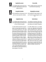 3
3
-
 4
4
-
 5
5
-
 6
6
-
 7
7
-
 8
8
-
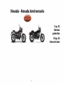 9
9
-
 10
10
-
 11
11
-
 12
12
-
 13
13
-
 14
14
-
 15
15
-
 16
16
-
 17
17
-
 18
18
-
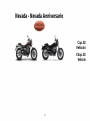 19
19
-
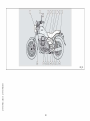 20
20
-
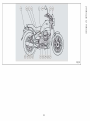 21
21
-
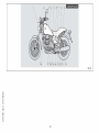 22
22
-
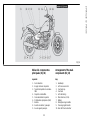 23
23
-
 24
24
-
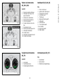 25
25
-
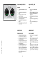 26
26
-
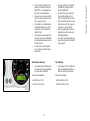 27
27
-
 28
28
-
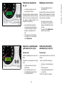 29
29
-
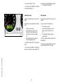 30
30
-
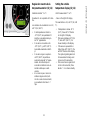 31
31
-
 32
32
-
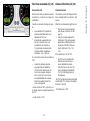 33
33
-
 34
34
-
 35
35
-
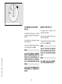 36
36
-
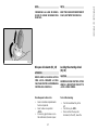 37
37
-
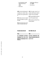 38
38
-
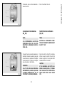 39
39
-
 40
40
-
 41
41
-
 42
42
-
 43
43
-
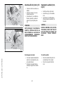 44
44
-
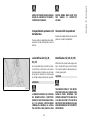 45
45
-
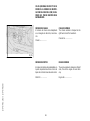 46
46
-
 47
47
-
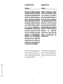 48
48
-
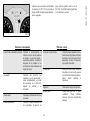 49
49
-
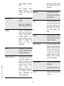 50
50
-
 51
51
-
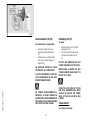 52
52
-
 53
53
-
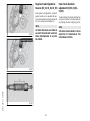 54
54
-
 55
55
-
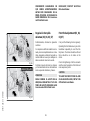 56
56
-
 57
57
-
 58
58
-
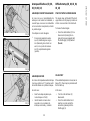 59
59
-
 60
60
-
 61
61
-
 62
62
-
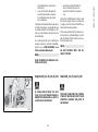 63
63
-
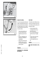 64
64
-
 65
65
-
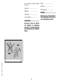 66
66
-
 67
67
-
 68
68
-
 69
69
-
 70
70
-
 71
71
-
 72
72
-
 73
73
-
 74
74
-
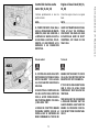 75
75
-
 76
76
-
 77
77
-
 78
78
-
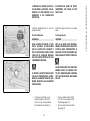 79
79
-
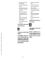 80
80
-
 81
81
-
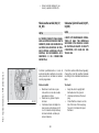 82
82
-
 83
83
-
 84
84
-
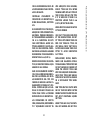 85
85
-
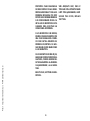 86
86
-
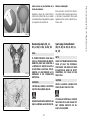 87
87
-
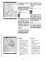 88
88
-
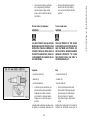 89
89
-
 90
90
-
 91
91
-
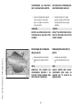 92
92
-
 93
93
-
 94
94
-
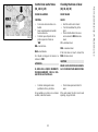 95
95
-
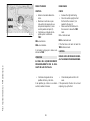 96
96
-
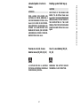 97
97
-
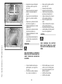 98
98
-
 99
99
-
 100
100
-
 101
101
-
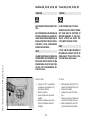 102
102
-
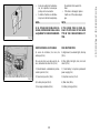 103
103
-
 104
104
-
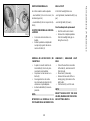 105
105
-
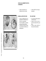 106
106
-
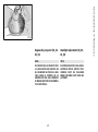 107
107
-
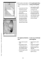 108
108
-
 109
109
-
 110
110
-
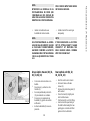 111
111
-
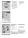 112
112
-
 113
113
-
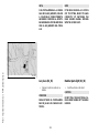 114
114
-
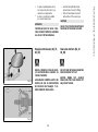 115
115
-
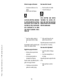 116
116
-
 117
117
-
 118
118
-
 119
119
-
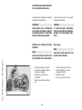 120
120
-
 121
121
-
 122
122
-
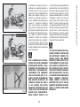 123
123
-
 124
124
-
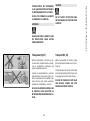 125
125
-
 126
126
-
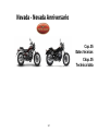 127
127
-
 128
128
-
 129
129
-
 130
130
-
 131
131
-
 132
132
-
 133
133
-
 134
134
-
 135
135
-
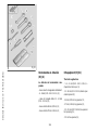 136
136
-
 137
137
-
 138
138
-
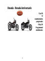 139
139
-
 140
140
-
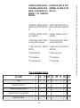 141
141
-
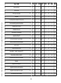 142
142
-
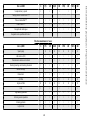 143
143
-
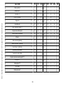 144
144
-
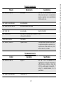 145
145
-
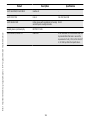 146
146
-
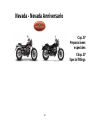 147
147
-
 148
148
-
 149
149
-
 150
150
-
 151
151
-
 152
152
-
 153
153


MOTO GUZZI nevada Manual de usuario
- Categoría
- Motocicletas
- Tipo
- Manual de usuario
- Este manual también es adecuado para
en otros idiomas
- English: MOTO GUZZI nevada User manual
Artículos relacionados
-
MOTO GUZZI BELLAGIO Manual de usuario
-
-
MOTO GUZZI V7 CLASSIC Manual de usuario
-
-
-
-
-
-
-