
Istruzioni ed avvertenze per l’installazione e l’uso
Instructions and warnings for installation and use
Instrucciones y advertencias para su instalación y uso
Anleitungen und Hinweise zu Installation und Einsatz
Instruções e advertências para a instalação e utilização
Instructions et avertissements pour l’installation et l’usage
CBX10224
CBX10224F
Control unit for a 24 Vdc motor, for a sliding gate, up-and-over door or barrier
Steuergerät für einen Motor 24 Vdc, für Schiebetor, Schwingtor oder Schrankenönung
Centrale per un motore 24 Vdc, per cancello scorrevole, portone basculante o barriera
Logique de commande pour un moteur 24 Vdc, pour portail coulissant,
porte basculante ou barrieres
Central para un motor 24 Vdc, para puerta de corredera, portón basculante o barreras
Unidade para um motor 24 Vdc, para portão de correr, portão basculante ou barreira
Centrala do silnika 24 Vdc, napędzającego przesuwną bramę ogrodzeniową,
uchylną bramę garażową lub szlaban

2
EN
1
2
3
4
5
6
7
8
Safety warnings
2.1
2.2
2.3
2.4
4.1
4.2
4.3
4.4
4.5
5.1
5.2
Introducing the product
Description of the control unit
Description of the connections
Models and technical characteristics
List of cables required
Preliminary Checks
Installing the Product
Electric connections
Display during normal operation
Autolearning of the travel stroke
Transmitter learning procedure
Customising the system - BASIC MENU
Testing and commissioning
Testing
Commissioning
Further details - ADVANCED MENU
Instructions and warnings for the
nal user
EC declaration of conformity
pag. 3
pag. 4
pag. 4
pag. 4
pag. 4
pag. 5
pag. 5
pag. 6
pag. 6
pag. 7
pag. 9
pag. 9
pag. 10
pag. 14
pag. 14
pag. 14
pag. 15
pag. 20
pag. 135
TABLE OF CONTENTS

3
EN
1 - SAFETY WARNINGS
ORIGINAL INSTRUCTIONS - important safety instructions. Fol-
low the instructions since incorrect installation can lead to se-
vere inquiry! Save these instructions.
Read the instructions carefully before proceeding with installation.
The design and manufacture of the devices making up the
product and the information in this manual are compliant with
current safety standards. However, incorrect installation or
programming may cause serious injury to those working on or
using the system. Compliance with the instructions provided
here when installing the product is therefore extremely impor-
tant.
If in any doubt regarding installation, do not proceed and contact the
Marantec Technical Service for clarications.
Under European legislation, an automatic door or gate system
must comply with the standards envisaged in the Directive
2006/42/EC (Machinery Directive) and in particular standards
EN 12453; EN 12635 and EN 13241-1, which enable declaration
of presumed conformity of the automation system.
Therefore, nal connection of the automation system to the electri-
cal mains, system testing, commissioning and routine maintenance
must be performed by skilled, qualied personnel, in observance of
the instructions in the “Testing and commissioning the automation
system” section.
The aforesaid personnel are also responsible for the tests required
to verify the solutions adopted according to the risks present, and for
ensuring observance of all legal provisions, standards and regula-
tions, with particular reference to all requirements of the EN 12453
standard which establishes the test methods for testing door and
gate automation systems.
Before starting installation, perform the following checks and
assessments:
ensure that every device used to set up the automation system is
suited to the intended system overall. For this purpose, pay special
attention to the data provided in the “Technical specications” sec-
tion. Do not proceed with installation if any one of these devices is
not suitable for its intended purpose;
check that the devices purchased are sucient to guarantee system
safety and functionality;
perform a risk assessment, including a list of the essential safety
requirements as envisaged in Annex I of the Machinery Directive,
specifying the solutions adopted. The risk assessment is one of the
documents included in the automation system’s technical le. This
must be compiled by a professional installer.
Considering the risk situations that may arise during instal-
lation phases and use of the product, the automation system
must be installed in compliance with the following safety pre-
cautions:
never make modications to any part of the automation system other
than those specied in this manual. Operations of this type can only
lead to malfunctions. The manufacturer declines all liability for da-
mage caused by unauthorised modications to products;
if the power cable is damaged, it must be replaced by the manufac-
turer or its after-sales service, or in all cases by a person with similar
qualications, to prevent all risks;
do not allow parts of the automation system to be immersed in water
or other liquids. During installation ensure that no liquids are able to
enter the various devices;
should this occur, disconnect the power supply immediately and
contact a Marantec Service Centre. Use of the automation system in
these conditions may cause hazards;
never place automation system components near to sources of heat
or expose them to naked lights. This may damage system compo-
nents and cause malfunctions, re or hazards;
The drive shall be disconnected from its power source during
cleaning, maintenance and when replacing parts. If the discon-
nect device is not in a visible location, ax a notice stating:
“MAINTENANCE IN PROGRESS”:
connect all devices to an electric power line equipped with an
earthing system;
the product cannot be considered to provide eective protection
against intrusion. If eective protection is required, the automation
system must be combined with other devices;
the product may not be used until the automation system “commis-
sioning” procedure has been performed as specied in the “Automa-
tion system testing and commissioning” section;
the system power supply line must include a circuit breaker device
with a contact gap allowing complete disconnection in the conditions
specied by class III overvoltage;
use unions with IP55 or higher protection when connecting hoses,
pipes or cable glands;
the electrical system upstream of the automation system must com-
ply with the relevant regulations and be constructed to good wor-
kmanship standards;
this appliance can be used by children aged from 8 years and above
and persons with reduced physical, sensory or mental capabilities or
lack of experience and knowledge if they have been given supervi-
sion or instruction concerning use of the appliance in a safe way and
understand the hazards involved;
before starting the automation system, ensure that there is no-one
in the immediate vicinity;
before proceeding with any cleaning or maintenance work on the
automation system, disconnect it from the electrical mains;
special care must be taken to avoid crushing between the part ope-
rated by the automation system and any xed parts around it;
children must be supervised to ensure that they do not play with the
equipment.
that the drive cannot be used with a driven part incorporating a wi-
cket door unless the drive can only be operated with the wicket door
in the safe position;
The automation system component packaging material must
be disposed of in full observance of current local waste dispo-
sal legislation.
Marantec reserves the right to amend these instructions if neces-
sary; they and/or any more recent versions are available at www.
marantec.com
Frequently examine the installation for imbalance where ap-
plicable and signs of wear or damage to cables, springs and
mounting.
Do not use if repair or adjustment is necessary.
ATTENTION !
ATTENTION !
ATTENTION !
ATTENTION !
ATTENTION !

4
EN
2.1 - Description of the control unit
The CBX10224 control unit is the most modern, ecient system for
the control of Marantec motors for the electric opening and closure
of sliding gates, up-and-over doors and electromechanical barrier.
All other, improper, use of the control unit is forbidden. The
2.2 - Description of the connections
1- Motor power supply connections and encoder
2- Transformer power supply connections
3- 24Vdc and 24Vac output connections to controls and safety
devices
4- Connector for battery charger KBP
5- Limit switch connector
6- Functions display
7- Safety device dip switch
8- Fuse 2A slow-acting
9- STOP-PH2-PH1-OPEN-CLOSE-PAR-SBS safety led and led
input led
10- Limit switch indicator LED LSC
11- Limit switch indicator LED LSO
12- STEPPING SBS button
13- UP + button
14- MENU button
15- DOWN - button
16- Antenna
17- KEY led
2.3 - Models and technical characteristics
CBX10224 has a display allowing easy programming and constant
monitoring of the input status; the menu structure also allows easy
setting of working times and operating modes.
2 - INTRODUCING THE PRODUCT
CODE DESCRIPTION
CBX10224 24V control unit for sliding gates, up-and-over doors or electromechanical barrier
CBX10224F 24V control unit FAST LINE for sliding gates, up-and-over doors or electromechanical barrier
NEG
PH-POW
STOP
STOP
STOP
STOP
PH2
PH1
OPEN
CLOSE
PAR
SBS
PH2
PH1
PH 2
COM
FLASH
IND
LED
SHIELD
UP
MENU
SBS
DOWN
(RADIO)
ANT
24 VAC
24 VAC
PH 1
OPEN
CLOSE
SBS
PAR
COM
POWER SUPPLY
NEG
ENC
V +
M -
M +
BATTERY
LS 1
LS 2
KEY
COM
1
4
16
8
2
5
7
9
6
17
3
10
11
13
12
15
14

5
EN
3 - PRELIMINARY CHECKS
2.4 - List of cables required
The cables required for connection of the various devices in a stan-
dard system are listed in the cables list table.
Before installing the product, perform the following checks and in-
spections:
check that the gate, the door or the barrier is suitable for automation;
the weight and size of the gate or door and the balance of the barrier
boom must be within the operating limits specied for the automa-
tion system in which the product is installed;
heck that the gate or door has rm, eective mechanical safety
stops;
make sure that the product xing zone is not subject to ooding;
high acidity or salinity or nearby heat sources might cause the pro-
duct to malfunction;
in case of extreme weather conditions (e.g. snow, ice, wide tempera-
ture variations or high temperatures), friction may increase, causing
a corresponding rise in the force needed to operate the system;
the starting torque may therefore exceed that required in normal
conditions;
check that when operated by hand the gate, the door or the barrier
moves smoothly without any areas of greater friction or derailment
risk;
check that the gate, door or the barrier is well balanced and will the-
refore remain stationery when released in any position;
check that the electricity supply line to which the product is to be
connected is suitably earthed and protected by an overload and dif-
ferential safety breaker device;
he system power supply line must include a circuit breaker device
with a contact gap allowing complete disconnection in the conditions
specied by class III overvoltage;
ensure that all the material used for installation complies with the
relevant regulatory standards.
The cables used must be suitable for the type of installation; for
example, an H03VV-F type cable is recommended for indoor appli-
cations, while H07RN-F is suitable for outdoor applications.
- Power supply with protection against short-circuits inside the con-
trol unit, on motors and on the connected accessories.
- Obstacle detection.
- Automatic learning of working times.
- Safety device deactivation by means of dip switches: there is no
need to bridge the terminals of safety devices which are not instal-
led - the function is simply disabled by means of a dip switch.
* If the power supply cable is more than 20 m long, it must be of larger gauge (3x2.5mm2) and a safety grounding system must be installed
near the automation unit.
TECHNICAL SPECIFICATIONS: CBX10224 CBX10224F
Power supply (L-N) 230 Vac (+10% - 15%) 50-60 Hz
Max motor load 150 W
Output for Vac accessories power/device test power Vdc
24 Vac without regulation 200 mA / 24 Vdc without regu-
lation 250 mA
Courtesy light output
24 Vdc 25 W
Flashing light output
Pause time Adjustable 0 - 900 sec. Adjustable 0,1 - 90 sec.
Operating temperature -20 °C + 55 °C
230 Vac power supply line fuses 1.6 A slow-acting
Max. number of transmitters storage
Compatible with all Marantec “Bi-Linked” transmitters
200
ELECTRIC CABLE TECHNICAL SPECIFICATIONS:
Connection cable maximum allowable limit
Control unit power supply line 1 x cable 3 x 1,5 mm
2
20 m *
Flashing light, courtesy light
Antenna
3 x 0,5 mm
2
**
1 x cable type RG58
20 m
20 m (advised < 5 m)
Electric lock 1 x cable 2 x 1 mm
2
10 m
Transmitter photocells 1 x cable 2 x 0,5 mm
2
20 m
Receiver photocells 1 x cable 4 x 0,5 mm
2
20 m
Sensitive edge 1 x cable 2 x 0,5 mm
2
20 m
Key-switch 1 x cable 4 x 0,5 mm
2
** 20 m

6
EN
4 - PRODUCT INSTALLATION
4.1 - Electrical connections
Before making the connections, ensure that the control unit is not powered up
ON
1 2 3
STOP
PH2
PH1
MOTOR CONNECTOR
Power supply connection terminal board
M + Power supply motor
M - Power supply motor
V + Power supply encoder
ENC Encoder signal
NEG Maximum encoder power supply
POWER SUPPLY CONNECTOR
L Power supply live 230 Vac (120 Vac) 50-60 Hz
N Power supply neutral 230 Vac (120 Vac) 50-60 Hz
Earth
DIP SWITCH
Set on “ON” to disable inputs STOP, PH1, PH2
Eliminates the need to bridge the terminal board inputs.
with the dip switch ON,
the safety devices are disabled
ATTENTION !
ATTENTION !
ELECTRICAL CONNECTIONS
FOR ENERGY SAVING
NEG
PH-POW
STOP
STOP
PH 2
COM
FLASH
IND
LED
24 VAC
24 VAC
PH 1
OPEN
CLOSE
SBS
PAR
COM
PHOTOTEST
OUTPUT LED
OPEN
PHOTOCELL 1
PHOTOCELL 2
CLOSE
PARCIAL
STEP BY STEP
COMMON
STOP/EDGE
INDICATOR
NEGATIVE
24 VAC
24 VAC
2
3
4
1
1
2
TX
RX
NC
PH2
2
3
4
1
1
2
TX
RX
PH1
GND
_
12/24
AC/DC
GND
_
12/24
AC/DC
COM
OUT
GND
_
12/24
AC/DC
GND
_
12/24
AC/DC
COM
OUT
NC
POWER
POWER SUPPLY
SUPPLY
N
T1,6A
L
230Vac
50/60Hz
COM
LED
FLASH
STOP
STOP
PH2
PH1
OPEN
CLOSE
PAR
SBS
PH2
PH1
SHIELD
UP
MENU
SBS
DOWN
(RADIO)
ANT
NEG
ENC
V +
M -
M +
BATTERY
LS 1
LS 2
KEY
COM
NEG
PH-POW
STOP
STOP
PH 2
COM
FLASH
IND
LED
24 VAC
24 VAC
PH 1
OPEN
CLOSE
SBS
PAR
COM
PHOTOTEST
OUTPUT LED
OPEN
PHOTOCELL 1
PHOTOCELL 2
CLOSE
PARCIAL
STEP BY STEP
COMMON
STOP/EDGE
INDICATOR
NEGATIVE
24 VAC
24 VAC
2
3
4
1
1
2
TX
RX
NC
PH2
2
3
4
1
1
2
TX
RX
PH1
GND
_
12/24
AC/DC
GND
_
12/24
AC/DC
COM
OUT
GND
_
12/24
AC/DC
GND
_
12/24
AC/DC
COM
OUT
NC
POWER
POWER SUPPLY
SUPPLY
N
T1,6A
L
230Vac
50/60Hz
STOP
STOP
PH2
PH1
OPEN
CLOSE
PAR
SBS
PH2
PH1
SHIELD
UP
MENU
SBS
DOWN
(RADIO)
ANT
NEG
ENC
V +
M -
M +
BATTERY
LS 1
LS 2
KEY
COM

7
EN
SAFETY AND CONTROL DEVICE CONNECTOR
COM Common for the FLASH-IND-LED inputs
FLASH Flashing light output 24Vdc (without regulation), maximum 25W
IND
IND output for gate open indicator light 24 Vdc not regulated 4W MAX / Electric lock output 12Vac, 15VA maximum
selectable with parameter IN.D.
LED
Courtesy light output 24Vdc (without regulation), maximum 25W, controllable also via radio ON-OFF command (radio
channel 4 selecting fC.y. = 2, tC.y. = 0)
24 VAC Accessories power supply 24 Vac without regulation, 200 mA (with battery operation output not active)
24 VAC Accessories power supply 24 Vac without regulation, 200 mA (with battery operation output not active)
NEG Accessories power supply negative
PH-POW
Photocells PH1 and PH2 power supply positive; phototest can be selected with parameter tp.h. 24 Vdc, 250 mA
STOP
STOP safety device, NC contact between STOP and STOP (warning, with dip switch 1 ON the safety device input is
o). This input is classied as a safety device; the contact can be deactivated at any time, cutting out the automation
system and disabling all functions, including Automatic Closure.
Safety sensor edge, ON/OFF, NC contact or resistive 8K2 between STOP and STOP.
Input selectable with parameter Ed.m.
PH2
Photocells (opening), NC contact between PH2 and COM (warning, with dip switch 2 ON the PHOTOCELL 2 safety
device input is o). The photocell is tripped at any time during opening of the automation system, halting operation
immediately; the automation system will continue opening when the contact is restored. In the event of intervention on
closure (parameter Ph.2. = 0) the device stops and on release re-opens.
PH1
Photocells (closing), NC contact between PH1 and COM (warning, with dip switch 3 ON the PHOTOCELL 1 safety
device input is o) The photocell is tripped at any time during closing of the automation system, halting operation im-
mediately and reversing the travel direction.
OPEN
OPEN command NO contact between OPEN and COM
Contact for the HOLD-TO-RUN function. The gate OPENS as long as the contact is held down
CLOSE
CLOSE command NO contact between CLOSE and COM
Contact for the HOLD-TO-RUN function. The gate CLOSES as long as the contact is held down
PAR
PARCIAL command NO contact between PAR and COM
Used to open the gate partially, depending on the software setting (not active in barrier/up-and-over mode)
SBS
STEPPING command NO contact between SBS and COM
Open/Stop/Close/Stop command, or as set in the software
COM Common for the PH2-PH1-OPEN-CLOSE-PAR-SBS inputs
SHIELD Antenna - shield -
ANT Antenna - signal -
4.2 - Display during normal operation
In “NORMAL OPERATING MODE”, i.e. when the system is powered up normally, the 3-gure LCD display shows the following status messages:
MESSAGES MEANING
--
Gate closed or switch-on after shutdown
OP
Gate opening
CL
Gate closing
SO
Gate stopped during opening
SC
Gate stopped during closure
F1
Photocell 1 tripped
F2
Photocell 2 tripped
ALI
Re-alignment procedure
oP
Gate stopped without automatic reclosure
-tC
Gate open with timed reclosure
Flashing dash counting in progress
L--
Learning started on limit switch (move the gate o the limit switch to continue the learning procedure) or lear-
ning stopped due to trip of safety device or motor inversion.
LOP
Learning opening
LCL
Learning closure
MESSAGES MEANING
-.-
Limit switch CLOSED (one dot between the two lines)
tC.
Limit switch OPEN (a point to the right)
SO
No limit switch active (no dots present)
In addition, the dots between the gures illustrate the status of the limit switches, as described in greater detail below:
n

8
EN
Malfunctions
This section lists a number of malfunctions which may occur.
SURGE OVERLOAD ALARM The motor’s current drawdown has increased very quickly
EOL
1. The gate has struck an obstacle.
2. Friction on runners or rack (see motor current [A]).
SAFETY EDGE ALARM The control unit has received a signal from the safety edge
EED
1. The safety edge has been pressed.
2. The safety edge is not connected correctly.
LIMIT SWITCH ALARM The limit switches are not working properly
ELS
1. The limit switches are damaged.
2. The limit switches are not connected.
3. Check the travel time which has passed without tripping of the limit switches.
After eliminating the cause of the alarm, to delete all errors simply
press the “DOWN -” key or press the SBS (STEPPING) command
The display returns to the normal screen.
PHOTOCELL ALARM/SAFETY EDGE Phototest fail outcome.
EPH
1. Check the photocell and the safety edge connections.
2. Check that the photocells and the safety edg are operating correctly.
ENCODER ALARM Encoder encoder (only if encoder is present)
EEN
1. Check the encoder connections.
2. Check that the encoder are operating correctly.
EVENT DESCRIPTION
KEY TO MAIN CONTROL
FLASHING LIGHT AND KEY LEDS
CONTROL UNIT
opening Gate opening
closure Gate closing
automatic closure Gate open with timed reclosure active
stop during closure Gate stopped during closure
stop during opening Gate stopped during opening
open Gate completely open without automatic reclosure
closed Gate completely closed
programmation During the programming phase 2 quick ashes + pause + 1 ash
obstacle M1 Motor 1 obstacle detected 4 quick ashes + pause, 3 times
photo 1! Photocell 1 tripped 2 quick ashes + pause, 3 times
photo 2! Photocell 2 tripped 2 quick ashes + pause, 3 times
sensitive edge! Sensitive edge tripped 5 quick ashes + pause, 3 times
parcial opening Parcial opening in progress
automatic parcial closure Gate opening to parcial position with timed reclosure activated
realignment Realignment after a manual release
phototest error Phototest error detected 3 quick ashes + pause, 3 times
encoder error Encoder error detected 7 quick ashes
DISPLAY MEANING
Status display (--, OP, CL, SO, ecc..) Description of the control unit (--, OP, CL, SO, ecc..)
Maneuvers performed Counter displays alternating the thousands (without dots) and the units (with dots).
Motor current [A] Current absorbed by the motor
Press “UP“ to read the following parameters on display.

9
EN
4.4 - Learning a transmitter
A transmitter can be “learned” via the specic programming menu or by remote memorisation, using a previously memorised transmitter.
UP
SBS
DOWN
MENU
4.3 - Autolearning of the travel stroke
The rst time the control unit is powered up, an autolearning proce-
dure must be carried out to acquire fundamental parameters such
as the travel stroke length and deceleration points.
AUTOLEARNING OF THE TRAVEL STROKE AND MAIN PARAMETERS
The decelerations will be those set in the menu, with the same percentage during both opening and closing.
1. Release the gate or door, move it onto the central position and lock it in place again.
2. Hold down the + and MENU buttons SIMULTANEOUSLY for more than 5 seconds, until the screen shows
LOP and get ready to press the DOWN key (see illustration) if necessary.
3. If the rst operation is NOT opening of the gate, press the DOWN key to stop the autolearning.
Then press SBS to restart the acquisition: the gate starts moving again, in the right direction. The motor
opens the gate at low speed to the opening limit switch. On reaching the opening limit switch, the gate re-
starts in the closing direction at low speed until it reaches the closing limit switch, displaying LCL.
4. Perform a number of opening, closing and sudden stop commands to ensure that the system is solid with
no assembly defects.
All the main parameters are set with the default settings by the control unit. To customise the installation, proceed as described in point 4.5
below.
CLEARING THE ENTIRE RECEIVER MEMORY
If you are in programming mode exit pressing the MENU button until -- appears. Press the DOWN (RADIO)
button for more than 2 seconds. Until the display shows the word “rd” (radio), then release the button
1. Press the DOWN (RADIO) button and hold it down until the LED lights up (about 3 seconds) and then goes
out (about 3 seconds). Release the key.
(>3s)-> (>3s)->
2. About 1 second after the key is released, the KEY LED starts to ash
(1s)+ (1s)+
3. Press the key on the receiver as the LED ashes for the third time
4. If the deletion has been successful, the KEY LED will give one long ash
3s
MEMORISING A REMOTE CONTROL
If you are in programming mode exit pressing the MENU button until -- appears. Press the DOWN (RADIO)
button for more than 2 seconds. Until the display shows the word “rd” (radio), then release the button
1. Press and release the DOWN (RADIO) button a number of times equal to the number of the function to be
selected: once for function STEP BY STEP, twice for function PARTIAL, three times for function ONLY OPEN,
four times for function LIGHT ON/OFF
+ +
2. The KEY LED will ash a number of times equal to the number of the function selected, with 1 second pauses
between ashes
+1s +1s
3. Press the back key of the remote control to be memorized and then press the front key within 7 seconds
2s
4. If the memorization has been successful, the KEY LED will give one long ash
3s
5. To memorize another remote control on the same function, repeat point 3
N.B If no commands are given for 7 seconds, the receiver automatically quits the programming mode
DELETING A REMOTE CONTROL
If you are in programming mode exit pressing the MENU button until -- appears. Press the DOWN (RADIO)
button for more than 2 seconds. Until the display shows the word “rd” (radio), then release the button
1. Press the DOWN (RADIO) button until the LED lights up (about 3 seconds), then release the button
(>3s)->
2. Press the key of the remote control to be deleted within 7 seconds
3. If the deletion has been successful, KEY LED will give one long ash
3s

10
EN
4.5 - Customising the system - BASIC MENU
If necessary, users may select a BASIC MENU which allows modi-
cation of the control unit’s basic parameters. To select the BASIC
MENU proceed as described below.
WARNING: to be certain of accessing the NORMAL OPERATION
display state, the starting point for accessing the BASIC MENU,
press the MENU key twice
Exampling of modifying a BASIC MENU parameter
UP
UP
UP
UP
UP UP
UP
DOWN
DOWN
DOWN
DOWN
DOWN DOWN
DOWN
MENU
MENU
MENU
MENU
MENU MENU
MENU
After accessing the BASIC
MENU, press the + and – keys
to scroll through the functions.
Press the MENU key quickly to
quit the menu.
Press the MENU key for 1 se-
cond to access the basic menu.
Press the + and – keys to scroll
through the functions to modify
other parameters.
Press the + and – keys to to
modify the value.
Press the MENU key for 1 se-
cond to display the parameter
in order to save the modied
value, or MENU quickly to quit
the function without saving.
To access the value modica-
tion function, press the MENU
key for 1 second, until the va-
lue starts to ash quickly.

11
EN
PARAMETERS DESCRIPTION DEFAULT MIN MAX UNIT
1
TCL
Automatic reclosure time (0 = o) 0 0 900 s
2
ttr
Reclosing time after transit on PH1
(0 = o)
0 0 30 s
3
SEI
Sensitivity on obstacles
0 = Maximum impact force
10 = Minimum impact force
3 0 10
4
SFO
Motor speed during opening
1 = minimum
2 = low
3 = medium
4 = high
5 = maximum
4 1 5
5
SSO
Motor speed during opening deceleration phase
1 = minimum
2 = low
3 = medium
4 = high
5 = maximum
1 1 5
6
SFC
Motor speed during closing
1 = minimum
2 = low
3 = medium
4 = high
5 = maximum
4 1 5
7
SSC
Motor speed during closing deceleration phase
1 = minimum
2 = low
3 = medium
4 = high
5 = maximum
1 1 5
8
SBS
STEP BY STEP or SBS conguration:
0 = Normal (AP-ST-CH-ST-AP-ST…)
1 = Alternate STOP (AP-ST-CH-AP-ST-CH…)
2 = Alternate (AP-CH-AP-CH…)
3 = Apartment block – timer
4 = Apartment block with immediate reclosure
0 *** 0 4
9
sT2
Additional stop input:
0 = disabled
1 = The PAR input becomes the STOP function. NO
contact input
0 0 1
10
LSI
Deceleration distance
0 to 100 = Motor deceleration percentage during
opening and closure
20 0 ** 100 %
11
BlT
Post blackout procedure
0 = No action, remains stationery
1 = Closure
0 0 1 s
12
SBY
Energy saving: enables photocell switch-o when gate
is closed
0= disabled
1= enabled
0 0 1
*** = The default value for barriers is 4
PARAMETERS CBX10224

EN
12
PARAMETERS CBX10224F - SU500F
PARAMETERS DESCRIPTION DEFAULT MIN MAX UNIT
1
TCL
Automatic reclosure time (0 = o) 0 0 900 s
2
ttr
Reclosing time after transit on PH1
(0 = o)
0 0 30 s
3
SEI
Sensitivity on obstacles
0 = Maximum impact force
10 = Minimum impact force
3 0 10
4
SFO
Motor speed during opening
1 = minimum
2 = low
3 = medium
4 = high
5 = maximum
5 1 5
5
SSO
Motor speed during opening deceleration phase
1 = minimum
2 = low
1 1 2
6
SFC
Motor speed during closing
1 = minimum
2 = low
3 = medium
4 = high
5 = maximum
5 1 5
7
SSC
Motor speed during closing deceleration phase
1 = minimum
2 = low
1 1 2
8
SBS
STEP BY STEP or SBS conguration:
0 = Normal (AP-ST-CH-ST-AP-ST…)
1 = Alternate STOP (AP-ST-CH-AP-ST-CH…)
2 = Alternate (AP-CH-AP-CH…)
3 = Apartment block – timer
4 = Apartment block with immediate reclosure
0 0 4
9
LSI
Deceleration distance in opening
from 5 to 100 = Motor deceleration percentage during
opening
20 5 100 %
10
LS2
Deceleration distance in closing
from 5 to 100 = Motor deceleration percentage during
closure
20 5 100 %
11
BlT
Post blackout procedure
0 = No action, remains stationery
1 = Closure
0 0 1
12
SBY
Energy saving: enables photocell switch-o when
barrier is closed
0= disabled
1= enabled
0 0 1

13
EN
PARAMETERS CBX10224F - PA3F
PARAMETERS DESCRIPTION DEFAULT MIN MAX UNIT
1
TCL
Automatic reclosure time (0 = o) 0 0 600 0,1 sec
2
ttr
Reclosing time after transit on PH1
(0 = o)
0 0 300 0,1 sec
3
SEI
Sensitivity on obstacles
0 = Maximum impact force
5 = Minimum impact force
0 0 5
4
SFO
Motor speed during opening
1 = minimum
2 = low
3 = medium
4 = high
5 = maximum
5 1 5
5
SFC
Motor speed during closing
1 = minimum
2 = low
3 = medium
4 = high
5 = maximum
5 1 5
6
SBS
STEP BY STEP or SBS conguration:
0 = Normal (AP-ST-CH-ST-AP-ST…)
1 = Alternate STOP (AP-ST-CH-AP-ST-CH…)
2 = Alternate (AP-CH-AP-CH…)
3 = Apartment block – timer
4 = Apartment block with immediate reclosure
4 0 4
7
LSI
Deceleration distance in opening
from 40 to 100 = Motor deceleration percentage
during opening
55 40 100 %
8
LS2
Deceleration distance in closing
from 40 to 100 = Motor deceleration percentage
during closure
68 40 100 %
9
BlT
Post blackout procedure
0 = No action, remains stationery
1 = Closure
0 0 1 sec
10
SBY
Energy saving: enables photocell switch-o when
barrier is closed
0= disabled
1= enabled
0 0 1

14
EN
5.2 Commissioning
Once all (and not just some) of the system devices have passed the
testing procedure, the system can be commissioned;
the system’s technical dossier must be produced and kept for 10
years. It must contain the electrical wiring diagram, a drawing or
photograph of the system, the analysis of the risks and the solutions
adopted to deal with them, the manufacturer’s declaration of con-
formity for all connected devices, the operator’s manual for every
device and the system maintenance plan;
x a dataplate with the details of the automation, the name of the
person who commissioned it, the serial number and year of con-
struction and the CE marking on the gate or door;
also t a sign specifying the procedure for releasing the system by
hand;
draw up the declaration of conformity, the instructions and precau-
tions for use for the end user and the system maintenance plan and
consign them to the end user;
ensure that the user has fully understood how to operate the system
in automatic, manual and emergency modes;
the end user must also be informed in writing about any risks and
hazards still present;
After detecting an obstacle, the gate or door stops during its
opening travel and automatic closure is disabled; to restart
operation, the user must press the control button or use the
transmitter.
5 - TESTING AND COMMISSIONING THE AUTOMATION SYSTEM
5.1 Testing
All system components must be tested following the procedures de-
scribed in their respective operator’s manuals;
ensure that the recommendations in Chapter 1 - Safety Warnings -
have been complied with;
check that the gate or door is able to move freely once the automa-
tion system has been released and is well balanced, meaning that it
will remain stationery when released in any position;
check that all connected devices (photocells, sensitive edges, emer-
gency buttons, etc.) are operating correctly by performing gate or
door opening, closing and stop tests using the connected control
devices (transmitters, buttons or switches);
perform the impact measurements as required by the EN12445
standard, adjusting the control unit’s speed, motor force and decele-
ration functions if the measurements do not give the required results,
until the correct setting is obtained.
The system must be tested by a qualied technician, who must per-
form the tests required by the relevant standards in relation to the
risks present, to check that the installation complies with the relevant
regulatory requirements, especially the EN12445 standard which
species the test methods for gate and door automation systems.
ATTENTION !

15
EN
6 - FURTHER DETAILS - ADVANCED MENU
The ADVANCED MENU allows the system to be further customised
by modifying parameters not accessible from the basic menu.
To access the ADVANCED menu, press the MENU key and hold it
down for 5 seconds.
To modify ADVANCED MENU parameters, proceed as described
for the BASIC MENU.
LEGENDA:
SL= sliding gate
BA= barrier
OH= up-and-over door
N.B. Some default functions/display items may vary with respect to
the type of motor selected.
PARAMETERS
DESCRIPTION DEFAULT MIN MAX UNIT TYPE
1
SP.h.
Use of PHOTO1 when starting from closed
0 = PHOTO1 is checked
1 = The gate starts even with PHOTO1 excited
1 0 1
SL/BA/
OH
2
Ph.2.
Use of PHOTO2
0 = Enabled during both opening and closing AP/CH
1 =Only enabled during opening AP
1 0 1
SL/BA/
OH
3
tP.h.
Photo-device test
0 = o
1 = PHOTO1 on
2 = PHOTO2 on
3 = PHOTO1 and PHOTO2 on
0 0 3
SL/BA/
OH
4
Ed.m.
STOP input selection
0 = STOP contact (NC)
1 = Resistive safety edge (8k2)
2 = Contact safety edge (NC)
0 0 2
SL/BA/
OH
5
iE.D.
Sensitive edge tripping mode
0= only tripped during closure with direction reversal
1 = stops the automation (during both opening and
closure) and retreats from the obstacle
0 0 1
SL/BA/
OH
6
tE.D.
Edge test
0 = o
1 = on
0 0 1
SL/BA/
OH
7
LP.o.
Parcial opening 50 10 100 % SL
8
TP.C.
Time for automatic closure from parcial opening (0=o) 0 0 900 s SL
9
FP.r.
Flashing light output setup
0 = Steady
1 = Flashing
2 = Two-colour LED strip for barrier (MODE 1)
- gate closed steady red
- gate open LEDs o
- during opening ashing green
- during closing ashing red
- stopped not on limit switch ashing red
3 = two-colour LED strip for barrier (MODE 2)
- gate closed steady red
- gate open steady green
- during opening ashing green
- during closing ashing red
- stopped not on limit switch ashing red
N.B.: if this parameter is set as 2 or 3, the settings of
parameter .D. will be ignored.
If this parameter is set as 2 or 3, the ashing light and gate
open light outputs will be used for operation with the LED strip
1 * 0 3
SL/BA/
OH
10
tP.r.
Pre-ashing time (0 = o) 0 0 20 s
SL/BA/
OH
11
FC.Y.
Courtesy light setup
0 = On at end of operation for time TCY
1 = On if gate not closed + duration of TCY
2 = On if courtesy light timer (TCY) time not out
0 0 2
SL/BA/
OH
12
tC.Y.
Courtesy light on time 0 0 900 s
SL/BA/
OH
n
PARAMETERS CBX10224

EN
16
PARAMETERS
DESCRIPTION DEFAULT MIN MAX UNIT TYPE
13
CL.E.
Clearance. Allows to stop before the fully open position: it
is useful to avoid mechanical stress during opening.
0 0 30 % BA/OH
14
de.a.
Hold-to-run
0 = o
1 = on
0 0 1
SL/BA/
OH
15
IN.D.
0 = deactivated
1 = gate open light ON/OFF
2 = gate open light proportional
- Slow ashing with gate opening
- Quick ashing with gate closing
- Steady light if gate open
- 2 ashes + pause with gate stationary (position other than
closed)
3 = Electric lock
4 = Magnetic electric lock function with output active when
gate/door is closed
N.B. interface with an external relay with 24 Vdc winding. To
activate this function, the pre-ash must be enabled at the
recommended value of 1 sec (tP.r. ≠ 0)
5 = LED strip for gate open light (MODE 1)
- steady light when open and closed
- ashing light in all other positions
6 = LED strip for gate open light (MODE 2)
- gate closed steady red
- gate open LEDs o
ashing red in all other positions
0 0 6
SL/BA/
OH
16
se.r.
Service interval cycle threshold.
(0 = o)
10 0 200
x 1000
cycles
SL/BA/
OH
17
se.f.
Enabling of continuous ashing indicating
service required with se.r. ≠ 0 (only active with gate
closed).
0 = o
1 = on
0 0 1
SL/BA/
OH
18
EL.T.
Electric lock activation time in seconds 4 1 10 s
SL/BA/
OH
19
ST.P.
High-speed motor start-up.
0 = on
1 = o
0 0 1
SL/BA/
OH
20
EN.C.
1 = O (use of virtual encoder)
2 = On (use of motor’s physical encoder)
1 1 2
SL/BA/
OH
21
NE.P.
1 to 10 pulses per revolution of the physical encoder 4 1 10
SL/BA/
OH
22
DE.F.
2 = Restore of factory settings for sliding gate motor
SU700M
3 = Restore of factory settings for sliding gate motor
SU1100M
4 = Factory setting restore for 4/6 mt barrier
5 = Factory setting restore for 8 mt barrier
0 0 5
SL/BA/
OH
To set the default values: 1) access the advanced programming
function; 2) select the “dEf” parameter”; 3) activate the modication
mode (“0” on display”); 4) accept the modication (press “MENU”
and hold it down). A countdown should now appear: 49,48...,1 down
to “don“. Release the key when nished.
To use both colours of a two-colour LED strip, make the connections
as explained in the CTLIGHT instructions and modify parameters
FP.r. as required (setting 2 or 3).
To use just one colour of a LED strip, make the connections as ex-
plained in the CTLIGHT instructions and modify parameter IN.D. as
required (setting 5 or 6); parameter FP.r. cannot be set on 2 or 3.
* = The default value for barriers is 3

17
EN
PARAMETERS CBX10224F - SU500F
PARAMETERS DESCRIPTION DEFAULT MIN MAX UNIT
1
SP.h.
Use of PHOTO1 when starting from closed
0 = PHOTO1 is checked
1 = The barrier starts even with PHOTO1 excited
1 0 1
2
Ph.2.
Use of PHOTO2
0 = Enabled during both opening and closing AP/CH
1 =Only enabled during opening AP
1 0 1
3
tP.h.
Photo-device test
0 = o
1 = PHOTO1 on
2 = PHOTO2 on
3 = PHOTO1 and PHOTO2 on
0 0 3
4
Ed.m.
STOP input selection
0 = STOP contact (NC)
1 = Resistive safety edge (8k2)
2 = Contact safety edge (NC)
0 0 2
5
iE.D.
Sensitive edge tripping mode
0= only tripped during closure with direction reversal
1 = stops the automation (during both opening and
closure) and retreats from the obstacle
0 0 1
6
tE.D.
Edge test
0 = o
1 = on
0 0 1
7
LP.o.
Parcial opening 50 30 100
8
TP.C.
Time for automatic closure from parcial opening (0=o) 0 0 900 sec
9
FP.r.
Flashing light output setup
0 = Steady
1 = Flashing
1 0 1
10
tP.r.
Pre-ashing time (0 = o) 0 0 20 sec
11
FC.Y.
(LED output)
Courtesy light setup
0 = On at end of operation for time TCY
1 = On if not closed + duration of TCY
2 = On if courtesy light timer (TCY) time not out
0 0 2
12
tC.Y.
Courtesy light on time, if FC.Y. dierent from 3
0 0 900 sec
13
IN.D.
0 = deactivated
1 = open light ON/OFF
2 = open light proportional
- Slow ashing with opening
- Quick ashing with closing
- Steady light if open
- 2 ashes + pause with barrier stationary (position other
than closed)
3 = Electric lock
4 = Magnetic electric lock function with output active when
gate is closed (tP.r.>0)
0 0 4
14
se.r.
Service interval cycle threshold.
(0 = o)
50 0 200
x 10.000
cycles
15
se.f.
Enabling of continuous ashing indicating
service required with se.r. ≠ 0 (only active with gate
closed).
0 = o
1 = on
1 0 1
16
EL.T.
Electric lock activation time in seconds 4 1 10
n

EN
18
PARAMETERS DESCRIPTION DEFAULT MIN MAX UNIT
17
DE.F.
1 = Restore of factory settings for sliding gate motors
SU500F
2 = Restore of factory settings for sliding barrier motor
PA3F
1 1 2
To set the default values: 1) access the advanced programming
function; 2) select the “dEf” parameter”; 3) activate the modication
mode; 4) accept the modication (press “MENU” and hold it down).
A countdown should now appear: 49,48...,1 down to “don“. Release
the key when nished.
* connect between COM and LED. to reset disconnect main power.
PARAMETERS DESCRIPTION DEFAULT MIN MAX UNIT
1
SP.h.
Use of PHOTO1 when starting from closed
0 = PHOTO1 is checked
1 = The barrier starts even with PHOTO1 excited
1 0 1
2
Ph.2.
Use of PHOTO2
0 = Enabled during both opening and closing AP/CH
1 =Only enabled during opening AP
1 0 1
3
tP.h.
Photo-device test
0 = o
1 = PHOTO1 on
2 = PHOTO2 on
3 = PHOTO1 and PHOTO2 on
0 0 3
4
Ed.m.
STOP input selection
0 = STOP contact (NC)
1 = Resistive safety edge (8k2)
2 = Contact safety edge (NC)
0 0 2
5
iE.D.
Sensitive edge tripping mode
0= only tripped during closure with direction reversal
1 = stops the automation (during both opening and
closure) and retreats from the obstacle
0 0 1
6
tE.D.
Edge test
0 = o
1 = on
0 0 1
8
FP.r.
Flashing light output setup
0 = Steady
1 = Flashing
2 = Two-colour LED disk for barrier
- barrier closed steady red
- barrier open steady green
- during opening steady green
- during closing steady red
- stopped not on limit switch steady red
2 0 2
9
tP.r.
Pre-ashing time (0 = o) 0 0 20 sec
10
FC.Y.
(LED output)
Courtesy light setup
0 = On at end of operation for time TCY
1 = On if barrier not closed + duration of TCY
2 = On if courtesy light timer (TCY) time not out
3* = Fault detection. Active in case of:
- motor overtravel >10 sec
- obstacle detection for 3 times
- limit switch error
- service maintenance reached
- encoder error
3 0 3
11
tC.Y.
Courtesy light on time, if FC.Y. dierent from 3
0 0 900 sec
* connect between COM and LED. to reset disconnect main power.
PARAMETERS CBX10224F - PA3F

19
EN
PARAMETS DESCRIPTION DEFAULT MIN MAX UNIT
12
IN.D.
(active if FP.r. dierent
from 2)
0 = deactivated
1 = barrier open light ON/OFF
2 = barrier open light proportional
- Slow ashing with barrier opening
- Quick ashing with barrier closing
- Steady light if barrier open
- 2 ashes + pause with barrier stationary (position other
than closed)
3 = Electric lock
4 = Magnetic electric lock function with output active when
barrier is closed
(tP.r.>0)
0 0 4
13
se.r.
Service interval cycle threshold.
(0 = o)
50 0 200
x 10.000
cycles
14
se.f.
Enabling of continuous ashing indicating
service required with se.r. ≠ 0 (only active with barrier
closed).
0 = o
1 = on
1 0 1
15
ST.P.
High-speed motor start-up.
0 = on
1 = o
1 0 1
16
DE.F.
1 = Restore of factory settings for sliding gate motors
SU500F
2 = Restore of factory settings for sliding barrier motor
PA3F
1 0 1

20
EN
Marantec Antriebs- und Steuerungstechnik GmbH & Co. KG produ-
ces systems for the automation of gates, garage doors, automatic
doors, roller blinds and car-park and road barriers. However, Ma-
rantec is not the manufacturer of your complete automation system,
which is the outcome of the analysis, assessment, choice of mate-
rials and installation work of your chosen installer. Every automation
system is unique, and only your installer has the experience and
skill required to produce a safe, reliable, durable system tailored to
your needs, and above all that complies with the relevant regulatory
standards. Although your automation system complies with the re-
gulation safety level, this does not rule out the presence of “residual
risk”, meaning the possibility that hazards may occur, usually due to
reckless or even incorrect use. We would therefore like to give you
some advice for the correct use of the system:
• before using the automation system for the rst time, have the in-
staller explain the potential causes of residual risks to you;
• keep the manual for future reference, and pass it on to any new
owner of the automation system;
• reckless use and misuse of the automation system may make it
dangerous: do not operate the automation system with people, ani-
mal or objects within its range of action;
• a properly designed automation system has a high level of safety,
since its sensor systems prevent it from moving with people or ob-
stacles present so that its operation is always predictable and safe.
However, as a precaution children should not be allowed to play clo-
se to the automation system, and to prevent involuntary activation,
remote controls must not be left within their reach;
• as soon as any system malfunction is noticed, disconnect the elec-
tricity supply and perform the manual release procedure. Never at-
tempt repairs on your own; call in your installation engineer. In the
meantime the door or gate can be operated without automation once
the geared motor has been released using the release key supplied
with the system. In the event of safety devices out of service arran-
ge for repairs to the automation immediately;
• in the event of malfunctions or power failures: while waiting for the
engineer to come (or for the power to be restored if your system is
not equipped with buer batteries), the door or gate can be used just
like any non-automated installation. To do this, the manual release
procedure must be carried out;
• manual release and operation: rst bear in mind that the release
procedure can only be carried out with the door or gate stationery.
• Maintenance: Like any machine, your automation system needs
regular periodic maintenance to ensure its long life and total safety.
Arrange a periodic maintenance schedule with your installation en-
gineer. Marantec recommends that maintenance checks should be
carried out every six months for normal domestic use, but this inter-
val may vary depending on the level of use. Any inspection, main-
tenance or repair work must only be carried out by qualied sta.
• Never modify the automation system or its programming and setup
parameters: this is the responsibility of your installation engineer.
• Testing, routine maintenance and any repairs must be recorded by
the person who performs them and the documents must be conser-
ved by the system’s owner.
The only procedures you are capable of, and which you are recom-
mended to perform, are cleaning of the photocell glass and removal
of any leaves or stones that may obstruct the automation system.
To prevent anyone from activating the gate or door, release the au-
tomation system before starting. Clean only with a cloth dipped in
a little water.
At the end of its useful life, the automation system must be disman-
tled by qualied personnel, and the materials must be recycled or
disposed of in compliance with the legislation locally in force.
If after some time your remote control seems to have become less
eective, or stops operating completely, the battery may be at (de-
pending on the level of use, this may take from several months up
to more than a year). You will realise this because the transmission
conrmation light does not come on, or only lights up for a very short
time.
Batteries contain pollutants: do not dispose of them with normal wa-
ste but follow the methods specied by the local regulations.
Thank you for choosing Marantec Antriebs- und Steuerungstechnik
GmbH & Co. KG; please visit our Internet site www.marantec.com
for further information.
7 - INSTRUCTIONS AND WARNINGS FOR THE END USER

21
DE
1
2
3
4
5
6
7
8
Sicherheitshinweise
2.1
2.2
2.3
2.4
4.1
4.2
4.3
4.4
4.5
5.1
5.2
Einführung in das Produkt
Beschreibung des Steuergerätes
Beschreibung der Anschlüsse
Modelle und technische Eigenschaften
Liste benötigter Kabel
Vorabkontrollen
Produktinstallation
Elektrische Anschlüsse
Anzeige Normalmodus
Einlernen des Laufs
Lernfunktion eines Senders
Benutzerdenierte Einrichtung der Anlage -
GRUNDMENÜ
Test und Inbetriebnahme
Abnahme
Inbetriebnahme
Vertiefung - ERWEITERTES MENÜ
Anweisungen und Hinweise für
den Endbenutzer
EG-Konformitätserklärung
S. 22
S. 23
S. 23
S. 23
S. 23
S. 24
S. 24
S. 25
S. 25
S. 26
S. 28
S. 28
S. 29
S. 33
S. 33
S. 33
S. 34
S. 39
S. 135
INHALTSVERZEICHNIS

22
DE
1 - SICHERHEITSHINWEISE
ORIGINALANWEISUNGEN – Wichtige Sicherheitsanweisun-
gen. Für die Sicherheit der Personen ist es wichtig, die folgen-
den Sicherheitsanweisungen zu befolgen. Bewahren Sie diese
Anweisungen auf.
Vor Durchführung der Installation lesen Sie die Anleitung bitte
aufmerksam durch.
Die Konstruktion und die Herstellung der Geräte, aus denen
sich das Produkt zusammensetzt, und die in diesem Handbuch
enthaltenen Informationen entsprechen den geltenden Si-
cherheitsvorschriften. Dennoch können eine falsche Installa-
tion und eine falsche Programmierung schwerwiegende Ver-
letzungen bei Personen verursachen, die die Arbeit ausführen,
und bei denen, die die Anlage benutzen werden. Aus diesem
Grund ist es wichtig, während der Installation strikt alle Anwei-
sungen in diesem Handbuch zu beachten.
Bei Zweifel jeglicher Art die Installation abbrechen und ggf. den Ma-
rantec Kundendienst zur Klärung kontaktieren.
Für die europäische Gesetzgebung muss der Einbau einer au-
tomatischen Tür oder eines automatischen Tors den Bestim-
mungen der Richtlinie 2006/42/EG (Maschinenrichtlinie) und im
Besonderen den Normen EN 12453, EN 12635 und EN 13241-1
entsprechen, die eine Konformitätserklärung der Automatisie-
rung ermöglichen.
In Anbetracht dessen müssen die endgültige Verbindung der Auto-
matisierung ans Stromnetz, die Endabnahme der Anlage, die Inbe-
triebnahme und die regelmäßige Wartung von qualiziertem und
erfahrenem Personal entsprechend den Anleitungen unter „Prüfung
und Inbetriebnahme der Automatisierung“ durchgeführt werden.
Außerdem muss das Personal auch die vorgesehenen Tests nach
den vorhandenen Risiken festlegen und die Einhaltung der Gesetze,
Vorschriften und Regeln überprüfen: insbesondere die Einhaltung
der Norm EN 12453, welche die Prüfverfahren für die Automatisie-
rung von Türen und Toren festlegt.
Vor Installationsbeginn folgende Analysen und Prüfungen dur-
chführen:
Sicherstellen, dass die für die Automatisierung vorgesehenen
Vorrichtungen für die zu realisierende Anlage geeignet sind. Die-
sbezüglich aufmerksam die im Kapitel „Technische Eigenschaften“
aufgeführten Daten prüfen. Die Installation nicht durchführen, wenn
auch nur eine der Vorrichtungen nicht für den Gebrauch geeignet ist.
Sicherstellen, dass die erworbenen Vorrichtungen ausreichend sind,
um die Sicherheit und Funktion der Anlage zu gewährleisten.
Die Risikoanalyse durchführen, welche auch die Liste der Si-
cherheitsanforderungen, aufgeführt in Anhang I der Maschinenricht-
linie, beinhalten muss, und die angewandten Lösungen nennen.Die
Risikoanalyse ist eine der Unterlagen, aus denen sich die techni-
schen Unterlagen der Automatisierung zusammensetzen. Diese
müssen von einem erfahrenen Installateur ausgefüllt werden.
In Anbetracht der Gefahrensituationen, die bei Installation und
Benutzung des Produktes auftreten können, muss die Automa-
tisierung unter Berücksichtigung folgender Hinweise installiert
werden:
Keine Änderungen an der Automatisierung vornehmen, wenn diese
nicht in diesem Handbuch vorgesehen sind. Diese können nur zu
Funktionsstörungen führen. Der Hersteller übernimmt keine Haftung
für Schäden, die durch eigenmächtige Änderungen am Produkt ve-
rursacht wurden.
Ist das Stromkabel beschädigt, muss es vom Hersteller, seinem
technischen Kundendienst oder einer ähnlich qualizierten Person
ersetzt werden, um Gefährdungen zu vermeiden;
Die einzelnen Komponenten der Automatisierung dürfen nicht in
Wasser oder andere Flüssigkeiten getaucht werden. Bei der In-
stallation darauf achten, dass keine Flüssigkeit ins Innere der Vor-
richtungen dringt.
Sollten Flüssigkeiten ins Innere der Automatisierungskomponenten
dringen, sofort die Stromzufuhr abschalten und sich an den Maran-
tec Kundendienst wenden. Die Benutzung der Automatisierung in
derartigen Situationen kann gefährlich sein.
Die einzelnen Komponenten weder Wärmequellen noch oenen
Flammen aussetzen. Dadurch können Schäden, Störungen und
Gefahrensituationen entstehen oder ein Brand ausbrechen
Die Einheit ist während der Reinigung, Wartung und Auswe-
chslung von Bestandteilen von der Speisung abzutrennen.
Sollte die Abschaltvorrichtung nicht sichtbar sein, ein Schild
mit der Aufschrift „IN WARTUNG“ anbringen.
Alle Vorrichtungen müssen mit einer Stromleitung verbunden wer-
den, die sicher geerdet ist.
Dieses Produkt kann nicht als ausreichendes System für den
Einbruchsschutz angesehen werden. Wenn Sie sich ausreichend
schützen wollen, müssen andere Vorrichtungen in die Automatisie-
rung integriert werden.
Wie im Absatz „Prüfung und Inbetriebnahme der Automatisierung“
vorgesehen, darf das Produkt erst nach der „Inbetriebnahme“ der
Automatisierung benutzt werden.
Im Stromnetz der Anlage eine Abschaltvorrichtung mit ausreichen-
dem Önungsabstand der Kontakte vorsehen, die, wie von der
Überspannungskategorie III gefordert, die komplette Abschaltung
erlaubt.
Verwenden Sie für die Verbindung von steifen und exiblen Rohren
oder Kabeldurchgängen Anschlüsse mit dem Schutzgrad IP55 oder
höher.
Die elektrische Anlage vor der Automatisierung muss den geltenden
Bestimmungen entsprechen und fachgerecht ausgeführt sein.
Das Gerät kann von Kindern im Alter von nicht weniger als 8 Jahren
und von Personen mit beschränkten körperlichen, sensoriellen und
geistigen Fähigkeiten oder ohne Erfahrung bzw. ohne das notwen-
dige Bewußtsein verwendet werden, vorausgesetzt, dass sie dabei
überwacht werden oder dass sie Anweisungen über den sicheren
Gebrauch des Gerätes und das Verständnis der damit verbundenen
Gefahren erhalten haben;
Vergewissern Sie sich vor der Inbetriebsetzung der Automatisie-
rung, dass sich keine Personen in unmittelbarer Nähe benden;
Vor jeder Reinigung und Wartung ist die Automatisierung vom
Stromnetz zu trennen;
Besondere Vorsicht ist geboten, um Quetschungen zwischen dem
geführten Teil und festen Elementen in der unmittelbaren Nähe zu
vermeiden;
Kinder sollten beaufsichtigt werden, um sicherzustellen, dass sie
nicht mit dem Gerät spielen.
Das Gerät darf mit einer automatisierten Tür mit eingebauter Fuß-
gängertür nicht verwendet werden.
ACHTUNG !
ACHTUNG !
ACHTUNG !
ACHTUNG !
ACHTUNG !
Die Anlage ist regelmäßig dahingehend zu prüfen, dass keine
Unwucht und Zeichen einer mechanischen Abnutzung, sowie
beschädigte Kabel, Federn und Stützelemente vorhanden sind.
Verwenden Sie nicht, wenn eine Reparatur oder Einstellung er-
forderlich ist.
Das Verpackungsmaterial aller Automatisierungskomponenten
muss entsprechend den örtlichen Bestimmungen entsorgt wer-
den.
Marantec behält sich vor, diese Anweisungen notfalls zu ändern;
diese Anweisungen und/oder eine neuere Version benden sich auf
der Website www.marantec.com

23
DE
2.1 - Beschreibung des Steuergerätes
Das Steuergerät CBX10224 ist das modernste und ezienteste Be-
triebssystem für die Motoren von Marantec zum elektrischen Önen
und Schließen von Schiebetoren, Garagentoren und elektromecha-
nischen Schranken. Jeder andere unsachgemäße Gebrauch des
Steuergerätes ist verboten.
2.2 - Beschreibung der Anschlüsse
1- Versorgungsanschlüsse Motor und encoder
2- Versorgungsanschlüsse Transformator
3- Ausgangsverbindungen 24Vdc und 24Vac, Bedienelemente und
Sicherheitsvorrichtungen
4- Verbinder für batterieladegerät KBP
5- Verbinder Endanschlag
6- Display für Funktionsanzeigen
7- Dip Switch Sicherheitsvorrichtungen
8- Sicherung 2A träge
9- STOP-PH2-PH1-OPEN-CLOSE-PAR-SBS Led Sicherheit und
Ledanzeige bedienungen
10- LSC led Anzeige Endschalter
11- LSO led Anzeige Endschalter
12- SBS taste Schrittbetrieb
13- UP taste +
14- MENU taste menu
15- DOWN taste -
16- Antenne
17- Led KEY
2.3 - Modelle und technische Eigenschaften
Das CBX10224 ist mit einem Display ausgestattet, das eine einfa-
che Programmierung und kontinuierliche Überwachung des Status
der Eingänge erlaubt. Außerdem gewährleistet der Menüaufbau
eine einfache Einstellung der Arbeitszeiten und der Betriebslogik.
2 - EINFÜHRUNG IN DAS PRODUKT
CODE BESCHREIBUNG
CBX10224 24-V-Steuergerät für einen Schiebe, Garagentoren oder elektromechanischen Schranken
CBX10224F 24-V-Steuergerät FAST LINE für einen Schiebe, Garagentoren oder elektromechanischen Schranken
NEG
PH-POW
STOP
STOP
STOP
STOP
PH2
PH1
OPEN
CLOSE
PAR
SBS
PH2
PH1
PH 2
COM
FLASH
IND
LED
SHIELD
UP
MENU
SBS
DOWN
(RADIO)
ANT
24 VAC
24 VAC
PH 1
OPEN
CLOSE
SBS
PAR
COM
POWER SUPPLY
NEG
ENC
V +
M -
M +
BATTERY
LS 1
LS 2
KEY
COM
1
4
16
8
2
5
7
9
6
17
3
10
11
13
12
15
14

24
DE
3 - VORABKONTROLLEN
2.4 - Liste benötigter Kabel
Die bei einer typischen Anlage erforderlichen Kabel für den
Anschluss der einzelnen Vorrichtungen sind in der Tabelle Kabelliste
aufgeführt.
Vor der Installation bitte folgende Punkte prüfen und kontrollieren:
Prüfen, dass das Tor, die Tür oder die Schranke für eine Automati-
sierung geeignet sind;
das Gewicht und die Abmessungen des Tores bzw. der Tür sowie
der Ausgleich des Schrankenbaums müssen innerhalb der Einsatz-
Grenzbestimmungen des Antriebes liegen, auf den das Produkt in-
stalliert wird;
kontrolle des Vorhandenseins und der Stärke der mechanischen Si-
cherheitsanschläge des Tors oder der Tür;
sicherstellen, dass der Befestigungsbereich nicht überutet werden
kann;
überhöhter Säure- oder Salzgehalt oder die Nähe von Wärmequel-
len können eine Funktionsstörung des Produktes verursachen;
bei extremen klimatischen Verhältnissen (wie z. B. Schnee, Eis,
hohe Temperaturunterschiede, hohe Temperaturen) könnten sich
die Reibungen verstärken; deshalb könnte der Kraftaufwand für die
Bewegung und das Anlaufmoment höher sein als im Normalzustand;
kontrollieren, dass eine sanfte manuelle Bewegung des Tors, der
Tür bzw. Schranke ohne Stellen mit stärkerem Widerstand möglich
ist und dass kein Risiko des Austreten aus den Führungsschienen
besteht;
kontrollieren, dass das Tor, die Tür bzw. Schranke im Gleichgewicht
sind und daher in jeder beliebigen Position stehen bleiben;
prüfen, dass die Stromleitung für den Anschluss des Produkts über
eine Sicherheitserdung verfügt und mit einem Leitungsschutz- und
Dierentialschalter geschützt ist;
im Stromnetz der Anlage eine Abschaltvorrichtung mit ausreichen-
dem Önungsabstand der Kontakte vorsehen, die, wie von der
Überspannungskategorie III gefordert, die komplette Abschaltung
erlaubt;
sicherstellen, dass das gesamte für die Installation benutzte Mate-
rial den geltenden Bestimmungen entspricht.
Die benutzten Kabel müssen dem Installationstyp entsprechen; z. B.
wird ein Kabel des Typs H03VV-F für Innenbereiche bzw. H07RN-F
für Außenbereiche empfohlen.
* Wenn das Versorgungskabel länger als 30 ist, muss ein Kabel mit größerem Querschnitt benutzt (3x2,5 mm
2
) und eine Sicherheitserdung
in der Nähe der Automatisierung installiert werden.
TECHNISCHE MERKMALE: CBX10224 CBX10224F
Spannungsversorgung (L-N) 230 Vac (+10% - 15%) 50-60 Hz
Motorhöchstlast 150 W
Ausgang Spannungsversorgung Zubehör Vac / Spannungsversorgung
Gerätetest Vdc
24 Vac ungeregelt 200 mA / 24 Vdc ungeregelt 250 mA
Ausgang zusätzliche Beleuchtung
24 Vdc 25 W
Ausgang Blinkleuchte
Pausenzeit Einstellbar 0 - 900 sec. Einstellbar 0,1 - 90 sec.
Betriebstemperatur -20 °C + 55 °C
Sicherungen Versorgungsleitung 230 Vac 1.6 A Träge
Max. Anzahl speicherbare Sender
Kompatibel mit allen Marantec „Bi-Linked“ -Sendern
200
TECHNISCHE SPEZIFIKATIONEN FÜR ELEKTRISCHE KABEL:
Anschluss kabelliste maximal zulässige Grenze
Elektrische Versorgungsleitung 1 x kabel 3 x 1,5 mm
2
20 m *
Blinkleuchte, zusätzliche Beleuchtung
Antenne
3 x 0,5 mm
2
**
1 x kabel typ RG58
20 m
20 m (empfohlen < 5 m)
Elektroschloss 1 x kabel 2 x 1 mm
2
10 m
Fotozellen Sender 1 x kabel 2 x 0,5 mm
2
20 m
Fotozellen Empfänger 1 x kabel 4 x 0,5 mm
2
20 m
Schaltleiste 1 x kabel 2 x 0,5 mm
2
20 m
Schlüsseltaster 1 x kabel 4 x 0,5 mm
2
** 20 m
- Gegen Kurzschlüsse im Steuergerät, an den Motoren und am an-
geschlossenen Zubehör geschützte Versorgung.
- Hinderniserkennung.
- Automatisches Erlernen der Arbeitszeit.
- Ausschaltung der Sicherheitseingänge durch Dip Switch: Die
Klemmen der nicht installierten Sicherheitsvorrichtungen müssen
nicht überbrückt werden; es reicht aus, die Funktion mit Dip Switch
zu sperren.

25
DE
4 - PRODUKTINSTALLATION
4.1 - Stromanschlüsse
Vor dem Anschluss sicherstellen, dass die Stromzufuhr des Steuergerätes abgeschaltet ist.
ON
1 2 3
STOP
PH2
PH1
MOTORVERBINDER
Klemmenleiste Versorgungsanschlüsse
M + Spannungsversorgung Motor
M - Spannungsversorgung Motor
V + Spannungsversorgung Encoder
ENC Encodersignal
NEG Masse Encoder-Speisung
STROMVERBINDER
L Phase 230 Vac (120 Vac) 50-60 Hz
N Nullleiter 230 Vac (120 Vac) 50-60 Hz
Erde
WÄHLSCHALTER DIP SWITCH
Bei Einstellung auf „ON“ sperrt er die Eingänge STOP, PH1,
PH2. Dadurch entfällt die Notwendigkeit, die Eingänge
auf der Klemmenleiste zu überbrücken.
Bei Einstellung des Dip Switch auf ON
sind die angeschlossenen
Sicherheitsvorrichtungen ausgeschlossen.
ACHTUNG !
ACHTUNG !
STROMANSCHLÜSSE FÜR
ENERGIEEINSPARUNG
NEG
PH-POW
STOP
STOP
PH 2
COM
FLASH
IND
LED
24 VAC
24 VAC
PH 1
OPEN
CLOSE
SBS
PAR
COM
PHOTOTEST
OUTPUT LED
OPEN
PHOTOCELL 1
PHOTOCELL 2
CLOSE
PARCIAL
STEP BY STEP
COMMON
STOP/EDGE
INDICATOR
NEGATIVE
24 VAC
24 VAC
2
3
4
1
1
2
TX
RX
NC
PH2
2
3
4
1
1
2
TX
RX
PH1
GND
_
12/24
AC/DC
GND
_
12/24
AC/DC
COM
OUT
GND
_
12/24
AC/DC
GND
_
12/24
AC/DC
COM
OUT
NC
POWER
POWER SUPPLY
SUPPLY
N
T1,6A
L
230Vac
50/60Hz
COM
LED
FLASH
STOP
STOP
PH2
PH1
OPEN
CLOSE
PAR
SBS
PH2
PH1
SHIELD
UP
MENU
SBS
DOWN
(RADIO)
ANT
NEG
ENC
V +
M -
M +
BATTERY
LS 1
LS 2
KEY
COM
NEG
PH-POW
STOP
STOP
PH 2
COM
FLASH
IND
LED
24 VAC
24 VAC
PH 1
OPEN
CLOSE
SBS
PAR
COM
PHOTOTEST
OUTPUT LED
OPEN
PHOTOCELL 1
PHOTOCELL 2
CLOSE
PARCIAL
STEP BY STEP
COMMON
STOP/EDGE
INDICATOR
NEGATIVE
24 VAC
24 VAC
2
3
4
1
1
2
TX
RX
NC
PH2
2
3
4
1
1
2
TX
RX
PH1
GND
_
12/24
AC/DC
GND
_
12/24
AC/DC
COM
OUT
GND
_
12/24
AC/DC
GND
_
12/24
AC/DC
COM
OUT
NC
POWER
POWER SUPPLY
SUPPLY
N
T1,6A
L
230Vac
50/60Hz
STOP
STOP
PH2
PH1
OPEN
CLOSE
PAR
SBS
PH2
PH1
SHIELD
UP
MENU
SBS
DOWN
(RADIO)
ANT
NEG
ENC
V +
M -
M +
BATTERY
LS 1
LS 2
KEY
COM

26
DE
VERBINDER FÜR SICHERHEITSVORRICHTUNGEN UND BEDIENELEMENTE
COM Gemeinsamer Leiter für Eingänge FLASH-IND-LED
FLASH Ausgang Blinkleuchte 24Vdc (ungeregelt), maximal 25W
IND
Ausgang IND Ausgang Kontrolllampe Tor geönet 24 Vdc ungeregelt 4W MAX / Ausgang Elektroschloss 12Vac, 15VA
maximal wählbar über Parameter IN.D.
LED
Ausgang zusätzliche Beleuchtung 24Vdc (ungeregelt), maximal 25W, Bedienung auch per Funk ON-OFF (4. Funkkanal
dazu fC.y. = 2, tC.y. = 0 auswählen)
24 VAC Spannungsversorgung Zubehör 24 Vac ungeregelt, 200 mA (mit Batteriebetrieb Ausgang nicht aktiv)
24 VAC Spannungsversorgung Zubehör 24 Vac ungeregelt, 200 mA (mit Batteriebetrieb Ausgang nicht aktiv)
NEG Spannungsversorgung Zubehör negativ
PH-POW
Positive Spannungsversorgung der Fotozellen PH1, PH2; Fototest wählbar über Parameter tp.h. 24 Vdc, 250 mA
STOP
STOP Sicherheitsvorrichtung NC-Kontakt zwischen STOP und STOP (Achtung: bei Dip Switch 1 auf ON wird der
Sicherungseingang gesperrt). Dieser Eingang wird als Sicherheitsvorrichtung angesehen; der Kontakt kann jederzeit
abgeschaltet werden, sodass die Automation sofort angehalten und jede Funktion, auch die automatische Schließung,
deaktiviert wird.
Eingang Schaltleiste, NC-Kontakt oder Widerstandskontaktleiste 8K2 zwischen STOP und STOP.
Eingang wählbar über Parameter Ed.m.
PH2
Fotozellen (Önung) NC-Kontakt zwischen PH2 und COM (Achtung: bei Dip Switch 2 auf ON wird der Sicherungsein-
gang gesperrt FOTOZELLE 2). Die Fotozelle spricht zu jedem Zeitpunkt während der Schließung der Automation an
und bewirkt die sofortige Blockierung der Bewegung mit Umkehr der Laufrichtung. IIm Falle eines Eingries während
des Schließvorganges (Parameter Ph.2. = 0) stoppt der Antrieb und önet nach dem Freisetzen wieder.
PH1
Fotozellen (Schließung) NC-Kontakt zwischen PH1 und COM (Achtung: bei Dip Switch 3 auf ON wird der Siche-
rungseingang gesperrt FOTOZELLE 1). Die Fotozelle spricht zu jedem Zeitpunkt während der Schließung der Auto-
mation an und bewirkt die sofortige Blockierung der Bewegung mit Umkehr der Laufrichtung.
OPEN
Befehl ÖFFNEN NO-Kontakt zwischen OPEN und COM
Kontakt TOTMANN- Funktion. Das Tor ÖFFNET, solange der Kontakt gedrückt wird.
CLOSE
Befehl SCHLIESSEN NO-Kontakt zwischen CLOSE und COM
Kontakt TOTMANN- Funktion. Das Tor SCHLIEßT, solange der Kontakt gedrückt wird.
PAR
Betätigung der TEILÖFFNUNG NO-Kontakt zwischen PAR und COM
Befehl zur teilweisen Önung des Flügels entsprechend der Softwareeinstellung (im Betriebsmodus Schranke/
Schwingtor nicht aktiv).
SBS
Befehl SCHRITTBETRIEB NO-Kontakt zwischen SBS und COM
Befehl Önen/Stopp/Schließen/Stopp oder je nach Softwareeinstellung.
COM Gemeinsamer Leiter für Eingänge PH2-PH1-OPEN-CLOSE-PAR-SBS
SHIELD Antenne - Schutzgeecht -
ANT Antenne - Signal -
4.2 - Anzeige Normalmodus
Im „NORMALMODUS“, d. h. bei normaler Stromspeisung des Systems, zeigt das LCD-Display mit 3 Ziern folgende Statusmeldungen:
ANZEIGEN BEDEUTUNG
--
Tor geschlossen oder Neustart nach Ausschalten
OP
Tor in Önung
CL
Tor in Schließung
SO
Tor in Önung angehalten
SC
Tor in Schließung angehalten
F1
Ansprechen Fotozelle 1
F2
Ansprechen Fotozelle 2
ALI
Verfahren zum Ausrichten
oP
Tor ohne automatisches Wiederschließen angehalten
-tC
Tor geönet mit zeitgesteuertem Wiederschließen
Blinkender Strich Zeitkontrolle läuft
L--
Einlernen am Endanschlag gestartet (das Tor vom Endanschlag wegbewegen, um den Einlernvorgang fortzu-
setzen) oder Lernfunktion gestoppt wegen Auslösung von Sicherheitsschaltern oder Reversierung des Motors.
LOP
Einlernen bei Önung
LCL
Einlernen bei Schließung
ANZEIGEN BEDEUTUNG
-.-
Endanschlag GESCHLOSSEN (zwischen den zwei Ziern ist ein Linien)
tC.
Endanschlag OFFEN (ein Punkt auf der rechten Seite)
SO
Kein Endanschlag eingeschaltet (kein Punkt vorhanden)
Zusätzlich zeigen die Punkte zwischen den unten genannten Ziern den Endschalterstatus wie folgt an:
n

27
DE
Betriebsstörungen
In diesem Absatz werden einige Betriebsstörungen aufgelistet, die auftreten können.
ALARM IMPULSÜBERLAST Der Strom des Motors ist sehr schnell gestiegen
EOL
1. Das Tor ist auf ein Hindernis gestoßen.
2. An der Laufschiene oder Zahnstange sind Reibungen vorhanden (sehen Motor-
strom [A]).
ALARM SICHERHEITSLEISTE Das Steuergerät hat ein Signal der Sicherheitsleiste erfasst
EED
1. Die Sicherheitsleiste wird gedrückt.
2. Die Sicherheitsleiste ist nicht sachgerecht angeschlossen.
ALARM ENDANSCHLAG Die Endanschläge funktionieren nicht sachgemäß
ELS
1. Die Endanschläge sind beschädigt.
2. Die Endanschläge sind nicht angeschlossen.
3. Prüfen, wie lange das Tor bewegt wurde, ohne dass die Endanschläge bean-
sprucht wurden
Nach Aufhebung des Alarms zum Löschen aller Fehlermeldungen
die Taste „DOWN -“
oder das Bedienelement SBS (SCHRITTBETRIEB) drücken.
Das Display kehrt wieder zur normalen Anzeige zurück.
EREIGNIS BESCHREIBUNG
ANZEIGE BLINKLICHT UND
KEY-LED DES STEUERGERÄTS
Önung Tor in Önung
Schließung Tor in Schließung
Automatische Schließung Tor geönet mit zeitgesteuertem Wiederschließen aktiviert
Stopp bei Schließung Tor in Schließphase angehalten
Stopp bei Önung Tor in Önungsphase angehalten
geönet Tor vollständig geönet ohne automatisches Wiederschließen
geschlossen Tor vollständig geschlossen
Programmierung Während der Programmierphase 2-mal schnelles Blinken + Pause + 1-mal Blinken
Hindernis M1 Hindernis Motor 1 erkannt 4-mal schnelles Blinken + Pause insgesamt 3-mal
Foto 1! Ansprechen Fotozelle 1 2-mal schnelles Blinken + Pause insgesamt 3-mal
Foto 2! Ansprechen Fotozelle 2 2-mal schnelles Blinken + Pause insgesamt 3-mal
Schaltleiste! Ansprechen Schaltleiste
5-mal schnelles Blinken + Pause insgesamt 3-mal
Teilönung Teilönung erfolgt
Automatische
Teilschließung
Tor teilgeönet mit zeitgesteuertem Wiederschließen
Wiederanpassung Wiederanpassung nach einer Entriegelung von Hand
Fehler Fototest Fototest-Fehler erkannt 3-mal schnelles Blinken + Pause insgesamt 3-mal
Fehler Encoder Encoder-Fehler erkannt 7-mal schnelles Blinken
MASSE BEDEUTUNG
Statusanzeige (--, OP, CL, SO, ecc..) Status und beschreibung des Displays (--, OP, CL, SO, ecc..)
Ausgeführte bewegungen
Bewegungszählung, die Tausende (ohne Punkte) und die Einheiten (mit Punkten)
wechseln sich ab.
Motorstrom [A] Stromaufnahme des Motors
Durch Drücken der Taste „UP“ erscheinen auf dem Display folgende Parameter.
ALARM FOTOZELLEN/
SICHERHEITSLEISTE
Der Fototest hat ein negatives Ergebnis erbracht
EPH
1. Die Anschlüsse der Fotozellen und der Sicherheitsleiste kontrollieren.
2. Prüfen, dass die Fotozellen und die Sicherheitsleiste korrekt funktionieren.
ALARM ENCODER Encoder-Fehler (nur wenn Encoder vorhanden)
EEN
1. Die Anschlüsse des Encoders kontrollieren.
2. Prüfen, dass der Encoder korrekt funktioniert.

28
DE
4.4 - Lernfunktion eines Senders
Die Lernfunktion eines Senders kann mit dem spezischen Programmierungsmenü durchgeführt werden, oder durch Fernspeicherung mit
einem bereits gespeicherten Sender.
UP
SBS
DOWN
MENU
4.3 - Einlernen des Laufs
Bei der ersten Stromversorgung des Steuergeräts muss ein Einlern-
vorgang durchgeführt werden, der die Ermittlung grundlegender Pa-
rameter wie Lauänge und Verlangsamungen erlaubt.
EINLERNEN DES LAUFS UND DER HAUPTPARAMETER
Die Verlangsamungen werden entsprechend der Einstellung im Menü durchgeführt werden, wobei der Pro-
zentwert sowohl beim Önen als auch beim Schließen gleich ist.
1. Das Tor oder die Tür entriegeln, in mittlere Stellung bringen und wieder anhalten.
2. GLEICHZEITIG die Tasten + und MENU mehr als 5 Sekunden drücken, bis LOP angezeigt wird, und sich
zum Drücken (falls nötig) der Taste DOWN bereithalten (siehe Abbildung).
3. Wenn die erste Bewegung KEINE Önung ist, die Taste DOWN drücken, um den Einlernvorgang zu
stoppen. Dann SBS drücken, damit der Lernvorgang wieder startet: Das Tor setzt sich in die richtige Richtung
in Bewegung. Der Motor önet mit geringer Geschwindigkeit bis zum Erreichen des Endanschlags für die
Önung. Nach Erreichen des Önungs-Endschalters bewegt sich das Tor wieder mit langsamer Geschwin-
digkeit in die Schließrichtung, bis es den Schließ-Endschalter erreicht und LCLangezeigt wird.
5. Einige Önungs-, Schließbewegungen und plötzliche Stopps durchführen, um sicherzustellen, dass das
System verlässlich ist und keine Montagefehler vorliegen.
Alle wichtigen Parameter werden standardmäßig vom Steuergerät konguriert. Zur benutzerdenierten Einrichtung der Installation mit dem
nächsten Absatz 4.5 fortfahren.
SPEICHERUNG EINER FUNKSTEUERUNG
Wenn man sich in der Programmierungsphase des Antriebes bendet, das Menü mit dem Taster MENÜ verlas-
sen bis der Schriftzug --erscheint. Über 2 Sekunden lang auf den Taster DOWN (FUNK) drücken, bis auf dem
Display die Meldung “rd” (Funk) erscheint; danach den Taster wieder loslassen
1. Die Taste so oft betätigen und loslassen, wie es der Nummer des Ausgangs entspricht, der aktiviert werden
soll: 1 mal für Ausgang STEP BY STEP, 2 mal für Ausgang PARCIAL, 3 mal für Ausgang ONLY OPEN, 4 mal für
Ausgang LIGHT ON/OFF
+ +
2. Die LED KEY blinkt mit der Anzahl, die dem gewählten Ausgang entspricht, unterbrochen von einer Pause von
1 Sekunde
+1s +1s
3. Drücken Sie die Rücktaste der Fernbedienung, die gespeichert werden soll, und drücken Sie dann innerhalb
von 7 Sekunden die Vordertaste
2s
4. War die Speicherung erfolgreich, meldet der LED KEY dies durch 1 langes Blinken
3s
5. Für die Speicherung einer weiteren Funksteuerung auf den selben Ausgang ist Punkt 3 zu wiederholen
N.B Wird innerhalb von 7 Sekunden keine Taste betätigt, verlässt der Empfänger automatisch die Program-
mierphase
LÖSCHEN EINER FUNKSTEUERUNG
Wenn man sich in der Programmierungsphase des Antriebes bendet, das Menü mit dem Taster MENÜ verlas-
sen bis der Schriftzug --erscheint. Über 2 Sekunden lang auf den Taster DOWN (FUNK) drücken, bis auf dem
Display die Meldung “rd” (Funk) erscheint; danach den Taster wieder loslassen
1. Die Taste des DOWN (RADIO) so oft betätigen, bis die LED aueuchtet (ca. 3 Sekunden)
(>3s)->
2. Innerhalb von 7 Sekunden die Taste der Funksteuerung, die gelöscht werden soll, so lange betätigen, bis die
LED KEY erlischt. Die Taste der Funksteuerung loslassen
3. War die Speicherung erfolgreich, meldet der LED KEY dies durch 1 langes Blinken
3s
LÖSCHEN DES KOMPLETTEN EMPFÄNGERSPEICHERS
Wenn man sich in der Programmierungsphase des Antriebes bendet, das Menü mit dem Taster MENÜ verlas-
sen bis der Schriftzug --erscheint. Über 2 Sekunden lang auf den Taster DOWN (FUNK) drücken, bis auf dem
Display die Meldung “rd” (Funk) erscheint; danach den Taster wieder loslassen
1. Die Taste DOWN (RADIO) drücken und gedrückt halten, bis die LED (ca. 3 Sekunden) aueuchtet und dann
erlischt ( ca. 3 Sekunden). Die Taste loslassen
(>3s)-> (>3s)->
2. Ca. 1 Sekunde nach dem Loslassen der Taste beginnt die LED KEY zu blinken
(1s)+ (1s)+
3. Die Taste des Empfängers beim dritten Blinken betätigen
4. War das Löschen erfolgreich, meldet der LED KEY dies durch 1 langes Blinken
3s

29
DE
Falls nötig, kann man ein GRUNDMENÜ wählen, mit dem die
Grundparameter des Steuergeräts geändert werden können. Für
die Wahl des GRUNDMENÜS wie folgt vorgehen.
ACHTUNG: Um sicher zum Anzeigestatus zu kommen, der als
NORMALFUNKTION bezeichnet wird und der Ausgangspunkt für
den Zugri auf das GRUNDMENÜ ist, zweimal die Taste MENU drü-
cken.
Beispiel einer Parameteränderung im GRUNDMENÜ
UP
UP
UP
UP
UP UP
UP
DOWN
DOWN
DOWN
DOWN
DOWN DOWN
DOWN
MENU
MENU
MENU
MENU
MENU MENU
MENU
Zum Scrollen der Funktio-
nen die Tasten + und – im
GRUNDMENÜ drücken.
Zum Verlassen des Menüs
kurz die Taste MENU drücken.
1 Sekunde die Taste MENU drü-
cken, um das GRUNDMENÜ
zu önen.
Zum Scrollen der Funktionen
für die Änderung anderer Para-
meter die Taste + oder – drü-
cken.
Zur Wertänderung die Tasten +
und – drücken.
Zur Speicherung des geänder-
ten Werts 1 Sekunde lang die
Taste MENU drücken, bis der
Wert dauerhaft angezeigt wird,
oder zum schnellen Verlassen
ohne Speicherung kurz MENU
drücken.
Um die Wertänderung zu
önen, 1 Sekunde lang die
Taste MENU drücken, bis der
Wert schnell blinkt.
4.5 - Benutzerdenierte Einrichtung der Anlage - GRUNDMENÜ

30
DE
PARAMETER BESCHREIBUNG STANDARD MIN MAX EINHEIT
1
TCL
Automatische Wiederschließzeit (0 = deaktiviert) 0 0 900 s
2
ttr
Wiederschließzeit nach Durchfahrt auf PH1
(0 = deaktiviert)
0 0 30 s
3
SEI
Empndlichkeit gegenüber Hindernis
0 = Höchste Aufprallkraft
10 = Mindeste Aufprallkraft
3 0 10
4
SFO
Geschwindigkeit des Motors bei Önung
1 = minimal
2 = niedrig
3 = mittel
4 = hoch
5 = maximal
4 1 5
5
SSO
Geschwindigkeit des Motors bei Önung während der
Verlangsamungsphase.
1 = minimal *
2 = niedrig *
3 = mittel
4 = hoch
5 = maximal
1 1 5
6
SFC
Geschwindigkeit des Motors bei Schließung
1 = minimal
2 = niedrig
3 = mittel
4 = hoch
5 = maximal
4 1 5
7
SSC
Geschwindigkeit des Motors beim Schließen während
der Verlangsamungsphase.
1 = minimal *
2 = niedrig *
3 = mittel
4 = hoch
5 = maximal
1 1 5
8
SBS
Konguration SCHRITTBETRIEB oder SBS:
0 = Normal (AP-ST-CH-ST-AP-ST…)
1 = Wechselweise STOP (AP-ST-CH-AP-ST-CH…)
2 = Wechselweise (AP-CH-AP-CH…)
3 = Wohngebäude – Timer
4 = Wohngebäude mit sofortiger Schließung
0 *** 0 4
9
sT2
Zusätzlicher Stopp-Eingang:
0 = deaktiviert
1 = Der PAR-Eingang wird die STOP-Funktion. N.O.
Kontakt Eingang
0 0 1
10
LSI
Wirkbereich der Verlangsamung
Von 0 bis 100 = Prozentualer Anteil der
Verlangsamung bei der Schließ- und
Önungsbewegung
20 0 ** 100 %
11
BlT
Verhalten nach Stromausfall
0 = Keine Auswirkung, wie vorher
1 = Schließung
0 0 1 s
12
SBY
Energieeinsparung: Befähigung zum Abschalten der
Fotozellen bei geschlossenem Tor
0 = deaktiviert
1 = aktiviert
0 0 1
* = nur für SUN4224/SC4224
** = für SUN4224/SC4224 min 15
*** = Der Standardwert für die Barrieren ist 4
PARAMETER CBX10224

31
DE
PARAMETER BESCHREIBUNG STANDARD MIN MAX EINHEIT
1
TCL
Automatische Wiederschließzeit (0 = deaktiviert) 0 0 900 s
2
ttr
Wiederschließzeit nach Durchfahrt auf PH1
(0 = deaktiviert)
0 0 30 s
3
SEI
Empndlichkeit gegenüber Hindernis
0 = Höchste Aufprallkraft
10 = Mindeste Aufprallkraft
3 0 10
4
SFO
Geschwindigkeit des Motors bei Önung
1 = minimal
2 = niedrig
3 = mittel
4 = hoch
5 = maximal
5 1 5
5
SSO
Geschwindigkeit des Motors bei Önung während der
Verlangsamungsphase.
1 = minimal
2 = niedrig
1 1 2
6
SFC
Geschwindigkeit des Motors bei Schließung
1 = minimal
2 = niedrig
3 = mittel
4 = hoch
5 = maximal
5 1 5
7
SSC
Geschwindigkeit des Motors beim Schließen während
der Verlangsamungsphase.
1 = minimal
2 = niedrig
1 1 2
8
SBS
Konguration SCHRITTBETRIEB oder SBS:
0 = Normal (AP-ST-CH-ST-AP-ST…)
1 = Wechselweise STOP (AP-ST-CH-AP-ST-CH…)
2 = Wechselweise (AP-CH-AP-CH…)
3 = Wohngebäude – Timer
4 = Wohngebäude mit sofortiger Schließung
0 0 4
9
LSI
Wirkbereich der Verlangsamung Von 5 bis 100 =
Prozentualer Anteil der Verlangsamung bei der
Önungsbewegung
20 5 100 %
10
LS2
Wirkbereich der Verlangsamung Von 5 bis 100
= Prozentualer Anteil der Verlangsamung bei der
Schließ
20 5 100 %
11
BlT
Verhalten nach Stromausfall
0 = Keine Auswirkung, wie vorher
1 = Schließung
0 0 1
12
SBY
Energieeinsparung: Befähigung zum Abschalten der
Fotozellen bei geschlossenem Schrankenbaums
0 = deaktiviert
1 = aktiviert
0 0 1
PARAMETER CBX10224F - SU500F

32
DE
PARAMETER BESCHREIBUNG STANDARD MIN MAX EINHEIT
1
TCL
Automatische Wiederschließzeit (0 = deaktiviert) 0 0 600 0,1 sec
2
ttr
Wiederschließzeit nach Durchfahrt auf PH1
(0 = deaktiviert)
0 0 300 0,1 sec
3
SEI
Empndlichkeit gegenüber Hindernis
0 = Höchste Aufprallkraft
5 = Mindeste Aufprallkraft
0 0 5
4
SFO
Geschwindigkeit des Motors bei Önung
1 = minimal
2 = niedrig
3 = mittel
4 = hoch
5 = maximal
5 1 5
5
SFC
Geschwindigkeit des Motors bei Schließung
1 = minimal
2 = niedrig
3 = mittel
4 = hoch
5 = maximal
5 1 5
6
SBS
Konguration SCHRITTBETRIEB oder SBS:
0 = Normal (AP-ST-CH-ST-AP-ST…)
1 = Wechselweise STOP (AP-ST-CH-AP-ST-CH…)
2 = Wechselweise (AP-CH-AP-CH…)
3 = Wohngebäude – Timer
4 = Wohngebäude mit sofortiger Schließung
4 0 4
7
LSI
Wirkbereich der Verlangsamung Von 40 bis 100
= Prozentualer Anteil der Verlangsamung bei der
Önungsbewegung
55 40 100 %
8
LS2
Wirkbereich der Verlangsamung Von 40 bis 100
= Prozentualer Anteil der Verlangsamung bei der
Schließ
68 40 100 %
9
BlT
Verhalten nach Stromausfall
0 = Keine Auswirkung, wie vorher
1 = Schließung
0 0 1 sec
10
SBY
Energieeinsparung: Befähigung zum Abschalten der
Fotozellen bei geschlossenem Schrankenbaums
0 = deaktiviert
1 = aktiviert
0 0 1
PARAMETER CBX10224F - PA3F

33
DE
5.2 - Inbetriebnahme
Nach positivem Test aller (und nicht nur einiger) Vorrichtungen der
Anlage kann die Inbetriebnahme vorgenommen werden;
die technischen Unterlagen der Anlage müssen ausgestellt und
10 Jahre lang aufbewahrt werden; sie umfassen den Schaltplan,
die Zeichnung oder ein Foto der Anlage, die Risikoanalyse und
die jeweiligen Lösungen, die Konformitätserklärung des Herstel-
lers bezüglich aller angeschlossenen Vorrichtungen, die Gebrau-
chsanleitungen aller Geräte und den Wartungsplan der Anlage;
am Tor oder an der Tür ein Schild mit den Daten der Automation,
dem Namen des Verantwortlichen der Inbetriebnahme, der Serien-
nummer, dem Herstellungsjahr sowie dem CE-Zeichen anbringen;
ein Schild mit den notwendigen Handlungen zur manuellen Entrie-
gelung der Anlage anbringen;
die Konformitätserklärung ausfüllen und dem Endbenutzer zusam-
men mit der Gebrauchsanweisung und dem Wartungsplan der An-
lage aushändigen;
sicherstellen, dass der Benutzer den automatischen und manuellen
Betrieb und die Notausschaltung der Automation verstanden hat;
den Endbenutzer auch schriftlich über Gefahren und Risiken infor-
mieren;
Nach Erkennen eines Hindernisses hält das Tor oder die Tür
während der Önung an und die automatische Schließung wird
ausgeschlossen. Um die Bewegung fortzusetzen, muss man
die Bedientaste drücken oder den Sender benutzen.
5 - TEST UND INBETRIEBNAHME DER AUTOMATION
5.1 - Abnahme
Alle Komponenten der Anlage müssen gemäß den jeweiligen An-
weisungen der Handbücher endgeprüft werden;
kontrollieren, dass die Anweisungen des Kapitels 1 – Anweisungen
zur Sicherheit beachtet werden;
kontrollieren, dass sich das Tor oder die Tür nach der Entriegelung
der Automation frei bewegen können und sich in jeder Stellung im
Gleichgewicht benden und stillstehen;
die korrekte Funktion aller verbundenen Vorrichtungen (Fotozellen,
Schaltleisten, Notschalter und anderes) kontrollieren, indem man
mit den angeschlossenen Steuervorrichtungen (Sender, Tasten,
Wahlschalter) alle Proben der Önung, Schließung und Blockierung
des Tors oder der Tür durchführt;
die Messungen der Aufprallkraft nach EN12445 durchführen, dabei
Geschwindigkeit, Motorkraft und Verlangsamungen des Steuer-
geräts einstellen, falls die Messungen nicht die gewünschten Werte
zeigen.
Die Endabnahme der Anlage muss von einem qualizierten Tech-
niker durchgeführt werden, der die durch die einschlägigen Bestim-
mungen je nach bestehenden Gefahren vorgesehenen Prüfungen
ausführt und die Einhaltung der Anforderungen prüft. Besonders zu
berücksichtigen ist hierbei die Norm EN12445, welche die Prüfver-
fahren für Automationen an Türen und Toren festlegt.
ACHTUNG !

34
DE
6 - VERTIEFUNG - ERWEITERTES MENÜ
Das ERWEITERTE MENÜ erlaubt durch Parameteränderungen, die
nicht im GRUNDMENÜ möglich sind, eine weitere Anpassung der
Anlage an die persönlichen Bedürfnisse.
Für den Zugri auf das ERWEITERTE Menü die Taste MENU 5
Sekunden lang drücken.
Zur Änderung der Parameter des ERWEITERTEN MENÜS wie für
das GRUNDMENÜ angegeben vorgehen.
ZEICHENERKLÄRUNG:
SL= Schiebetor
BA= Schranke
OH= Schwingtor
Hinweis: Einige defaultmäßige Funktionen und Anzeigen können im
Vergleich zur gewählten Motorart anders sein.
PARAMETER BESCHREIBUNG STANDARD MIN MAX EINHEIT TYP
1
SP.h.
Verhalten PHOTO1 beim Start aus geschlossener Stellung
0 = Prüfung PHOTO1
1 = Das Tor önet auch bei belegter PHOTO1
1 0 1
SL/BA/
OH
2
Ph.2.
Verhalten PHOTO2
0 = Sowohl bei Önung als auch Schließung aktiviert
1 = Nur bei Önung aktiviert
1 0 1
SL/BA/
OH
3
tP.h.
Test Fotovorrichtungen
0 = deaktiviert
1 = aktiviert PHOTO1
2 = aktiviert PHOTO2
3 = aktiviert PHOTO1 und PHOTO2
0 0 3
SL/BA/
OH
4
Ed.m.
Wahl Eingang STOP
0 = STOP-Kontakt (NC)
1 = Widerstandskontaktleiste (8k2)
2 = Kontaktleiste (NC)
0 0 2
SL/BA/
OH
5
iE.D.
Ansprechverhalten Leiste
0= spricht nur bei Schließung mit Bewegungsumkehr an
1 = stoppt die Automation (sowohl bei Önung als auch
Schließung) und gibt das Hindernis frei
0 0 1
SL/BA/
OH
6
tE.D.
Test Leiste
0 = deaktiviert
1 = aktiviert
0 0 1
SL/BA/
OH
7
LP.o.
Teilönung 50 10 100 % SL
8
TP.C.
Automatische Wiederschließzeit von Teilönung (0 = deaktiviert) 0 0 900 s SL
9
FP.r.
Konguration Blinkleuchtenausgang
0 = Dauerhaft
1 = Blinkend
2 = zweifarbiger LED-Streifen für Schranke
(BETRIEBSMODUS 1)
- wenn geschlossen, rotes festes Licht
- wenn geönet, LEDs ausgeschaltet
- bei Önung, grünes Blinklicht
- bei Schließung, rotes Blinklicht
- nicht auf Endschaltern stehend, rotes Blinklicht
3 = zweifarbiger LED-Streifen für Schranke
(BETRIEBSMODUS 2)
- wenn geschlossen, rotes festes Licht
- wenn geönet, grünes festes Licht
- bei Önung, grünes Blinklicht
- bei Schließung, rotes Blinklicht
- nicht auf Endschaltern stehend, rotes Blinklicht
Anmerkung: Wird der Parameter auf 2 oder 3 gesetzt, dann
werden die Einstellungen des Parameters .D. ignoriert.
Bei Einstellung des Parameters auf 2 oder 3 wird der
Ausgang für die Blinkleuchte und die Kontrollleuchte ‚Tor
geönet’ für den Betrieb mit LED-Streifen verwendet
1 * 0 3
SL/BA/
OH
10
tP.r.
Vorblinkzeit (0 = deaktiviert) 0 0 20 s
SL/BA/
OH
11
FC.Y.
Konguration zusätzliche Beleuchtung
0 = Bei Bewegungsende über Zeitdauer TCY eingeschaltet
1 = Eingeschaltet bei nicht geschlossenem Tor + Dauer TCY
2 = Eingeschaltet, solange der Timer für
Zusatzbeleuchtung (TCY) nicht abgelaufen ist
0 0 2
SL/BA/
OH
12
tC.Y.
Dauer zusätzliche Beleuchtung 0 0 900 s
SL/BA/
OH
n
PARAMETER CBX10224

35
DE
PARAMETER BESCHREIBUNG STANDARD MIN MAX EINHEIT TYP
13
CL.E.
Clearance. Ermöglicht das Anhalten vor der ganz oenen
stellung zur schonung des mechanischen Anschlags bei
der Önung.
0 0 30 % BA/OH
14
de.a.
Totmann
0 = deaktiviert
1 = aktiviert
0 0 1
SL/BA/
OH
15
IN.D.
0 = deaktiviert
1 = Kontrollleuchte Tor geönet ON/OFF
2 = Kontrollleuchte Tor geönet proportional
- Langsames Blinken bei önendem Tor
- Schnelles Blinken bei schließendem Tor
- Festlicht bei oen stehendem Tor
- 2-maliges Blinken + Pause bei stehendem Tor (andere
Position als geschlossen)
3 = Elektroschloss
4 = Funktion aktives magnetisches AusgangsElektroschloss
bei geschlossener Automatisierung
Hinweis: Mit einem externen Relais mit 24 Vdc-Spule
verbinden. Zur Aktivierung dieser Funktion ist auch die
Freigabe des Vorblinkens mit einem empfohlenen Wert
von 1 Sek (tP.r. ≠ 0) erforderlich.
5 = LED-Streifen auf Kontrollleuchte ‚Tor geönet’
(BETRIEBSMODUS 1)
- Festlicht bei Önung und Schließung
- Blinklicht in allen anderen Positionen
6 = LED-Streifen auf Kontrollleuchte ‚Tor geönet’
(BETRIEBSMODUS 2)
- wenn geschlossen, rotes festes Licht
- wenn geönet, LEDs ausgeschaltet
Rotes Blinklicht in allen anderen Positionen
0 0 6
SL/BA/
OH
16
se.r.
Zyklengrenzwert Kundendienstanforderung
(0 = deaktiviert)
10 0 200
x 1000
Zyklen
SL/BA/
OH
17
se.f.
Freigabe des Dauerblinkens für die
Kundendienstanforderung mit se.r. ≠ 0 (nur bei
geschlossenem Tor).
0 = deaktiviert
1 = aktiviert
0 0 1
SL/BA/
OH
18
EL.T.
Elektroschloss-Aktivierungszeit in Sekunden 4 1 10 s
SL/BA/
OH
19
ST.P.
Schneller Start des Motors während der Startphase.
0 = deaktiviert
1 = aktiviert
0 0 1
SL/BA/
OH
20
EN.C.
1 = O (Verwendung des virtuellen Encoders)
2 = On (Verwendung des physikalischen Motorencoders)
1 1 2
SL/BA/
OH
21
NE.P.
Zwischen 1 und 10 Impulsen/Umdrehung des
physikalischen
4 1 10
SL/BA/
OH
22
DE.F.
2 = Rückstellung der Fabrikwerte für Schiebetormotor
SU700M
3 = Rückstellung der Fabrikwerte für Schiebetormotor
SU1100M
4 = Zurücksetzen auf die Fabrikwerte für 4/6 m Schranke
5 = Zurücksetzen auf die Fabrikwerte für 8 m Schranke
0 0 5
SL/BA/
OH
Zur Einstellung der Standardwerte: 1) Önen der erweiterten
Programmierung; 2) den Parameter „dEf“ wählen; 3) Änderung-
smodus aktivieren (angezeigt wird „0“); 4) Änderung annehmen
(„MENU“ drücken und gedrückt halten). An diesem Punkt muss die
Rückwärtszählung 49,48...,01 bis „don“ zu sehen sein. Zum Schluss
die Taste wieder loslassen.
Für den Betrieb mit LED-Streifen unter Verwendung beider Farben
Rot und Grün, die Anschlüsse gemäß CTLIGHT –Anleitungen befol-
gen und die Parameter FP.r. wie gewünscht ändern (Wert 2 oder 3).
Für den Betrieb mit LED-Streifen unter Verwendung nur einer Farbe,
die Anschlüsse gemäß CTLIGHT-Anleitungen befolgen und den Pa-
rameter IN.D. wie gewünscht ändern (Wert 5 oder 6); der Parameter
FP.r. darf nicht auf 2 oder 3 gestellt werden.
* = Der Standardwert für die Barrieren ist 3

36
DE
PARAMETER CBX10224F - SU500F
PARAMETER BESCHREIBUNG STANDARD MIN MAX
EINHEIT
1
SP.h.
Verhalten PHOTO1 beim Start aus geschlossener Stellung
0 = Prüfung PHOTO1
1 = Das Schrankenbaums önet auch bei belegter
PHOTO1
1 0 1
2
Ph.2.
Verhalten PHOTO2
0 = Sowohl bei Önung als auch Schließung aktiviert
1 = Nur bei Önung aktiviert
1 0 1
3
tP.h.
Test fotodispositivi
0 = disabilitato
1 = abilitato PHOTO1
2 = abilitato PHOTO2
3 = abilitato PHOTO1 e PHOTO2
0 0 3
4
Ed.m.
Wahl Eingang STOP
0 = STOP-Kontakt (NC)
1 = Widerstandskontaktleiste (8k2)
2 = Kontaktleiste (NC)
0 0 2
5
iE.D.
Ansprechverhalten Leiste
0= spricht nur bei Schließung mit Bewegungsumkehr an
1 = stoppt die Automation (sowohl bei Önung als auch
Schließung) und gibt das Hindernis frei
0 0 1
6
tE.D.
Test Leiste
0 = deaktiviert
1 = aktiviert
0 0 1
7
LP.o.
Teilönung 50 30 100
8
TP.C.
Automatische Wiederschließzeit von Teilönung (0 = deaktiviert) 0 0 900 sec
9
FP.r.
Konguration Blinkleuchtenausgang
0 = Dauerhaft
1 = Blinkend
1 0 1
10
tP.r.
Vorblinkzeit (0 = deaktiviert)
0 0 20 sec
11
FC.Y.
(LED Ausgang)
Konguration zusätzliche Beleuchtung
0 = Bei Bewegungsende über Zeitdauer TCY eingeschaltet
1 = Eingeschaltet bei nicht geschlossenem Schrankenbaums
+ Dauer TCY
2 = Eingeschaltet, solange der Timer für
Zusatzbeleuchtung (TCY) nicht abgelaufen ist
0 0 2
12
tC.Y.
Dauer zusätzliche Beleuchtung (se FC.Y. diverso da 3)
0 0 900 sec
13
IN.D.
0 = deaktiviert
1 = Kontrollleuchte Schrankenbaums geönet ON/OFF
2 = Kontrollleuchte Schrankenbaums geönet proportional
- Langsames Blinken bei önendem Schrankenbaums
- Schnelles Blinken bei schließendem Schrankenbaums
- Festlicht bei oen stehendem Schrankenbaums
- 2-maliges Blinken + Pause bei stehendem
Schrankenbaums (andere Position als geschlossen)
3 = Elektroschloss
4 = Funktion aktives magnetisches
AusgangsElektroschloss bei geschlossener
Automatisierung
(tP.r.>0)
0 0 4
14
se.r.
Zyklengrenzwert Kundendienstanforderung
(0 = deaktiviert)
50 0 200
x 10.000
cycles

37
DE
PARAMETER CBX10224F - PA3F
PARAMETER BESCHREIBUNG STANDARD MIN MAX EINHEIT
15
se.f.
Freigabe des Dauerblinkens für die
Kundendienstanforderung mit se.r. ≠ 0 (nur bei
geschlossenem Schrankenbaums).
0 = deaktiviert
1 = aktiviert
1 0 1
16
EL.T.
Elektroschloss-Aktivierungszeit in Sekunden 4 1 10
17
DE.F.
1 = Rückstellung der Fabrikwerte für Schiebetormotor
SU500F
2 = Zurücksetzen auf die Fabrikwerte für PA3F
Schranke
1 1 2
Zur Einstellung der Standardwerte: 1) Önen der erweiterten Pro-
grammierung; 2) den Paramete “def”; 3) Änderungsmodus aktivie-
ren (angezeigt wird „0“); 4) Änderung annehmen („MENU“ drücken
und gedrückt halten).. den Paramete An diesem Punkt muss die
Rückwärtszählung 49,48...,01 bis “don“. Zum Schluss die Taste
wieder loslassen.
PARAMETER BESCHREIBUNG STANDARD MIN MAX
EINHEIT
1
SP.h.
Verhalten PHOTO1 beim Start aus geschlossener Stellung
0 = Prüfung PHOTO1
1 = Das Schrankenbaums önet auch bei belegter
PHOTO1
1 0 1
2
Ph.2.
Verhalten PHOTO2
0 = Sowohl bei Önung als auch Schließung aktiviert
1 = Nur bei Önung aktiviert
1 0 1
3
tP.h.
Test fotodispositivi
0 = disabilitato
1 = abilitato PHOTO1
2 = abilitato PHOTO2
3 = abilitato PHOTO1 e PHOTO2
0 0 3
4
Ed.m.
Wahl Eingang STOP
0 = STOP-Kontakt (NC)
1 = Widerstandskontaktleiste (8k2)
2 = Kontaktleiste (NC)
0 0 2
5
iE.D.
Ansprechverhalten Leiste
0= spricht nur bei Schließung mit Bewegungsumkehr an
1 = stoppt die Automation (sowohl bei Önung als auch
Schließung) und gibt das Hindernis frei
0 0 1
6
tE.D.
Test Leiste
0 = deaktiviert
1 = aktiviert
0 0 1
8
FP.r.
Konguration Blinkleuchtenausgang
0 = Dauerhaft
1 = Blinkend
2 = zweifarbiger LED-Streifen für Schranke
(BETRIEBSMODUS 1)
- wenn geschlossen, rotes festes Licht
- wenn geöffnet, LEDs ausgeschaltet
- bei Öffnung, grünes Blinklicht
- bei Schließung, rotes Blinklicht
- nicht auf Endschaltern stehend, rotes Blinklicht
2 0 2
9
tP.r.
Vorblinkzeit (0 = deaktiviert) 0 0 20 s

38
DE
10
FC.Y.
(LED Ausgang)
Konguration zusätzliche Beleuchtung
0 = Bei Bewegungsende über Zeitdauer TCY eingeschaltet
1 = Eingeschaltet bei nicht geschlossenem Schrankenbaums
+ Dauer TCY
2 = Eingeschaltet, solange der Timer für
Zusatzbeleuchtung (TCY) nicht abgelaufen ist
3* = Meldung von Defekten. Schaltet in folgenden Fällen ein:
- Überlauf Motor >10 Sek.
- 3 konsekutive Hinderniserkennungen
- Fehler Endschalter
- Servicegrenze überschritten
- Fehler Encoder
3 0 3
11
tC.Y.
Dauer zusätzliche Beleuchtung (se FC.Y. diverso da 3)
0 0 900 s
12
IN.D.
0 = deaktiviert
1 = Kontrollleuchte Schrankenbaums geönet ON/OFF
2 = Kontrollleuchte Schrankenbaums geönet proportional
- Langsames Blinken bei önendem Schrankenbaums
- Schnelles Blinken bei schließendem Schrankenbaums
- Festlicht bei oen stehendem Schrankenbaums
- 2-maliges Blinken + Pause bei stehendem
Schrankenbaums (andere Position als geschlossen)
3 = Elektroschloss
4 = Funktion aktives magnetisches
AusgangsElektroschloss bei geschlossener
Automatisierung
(tP.r.>0)
0 0 4
13
se.r.
Zyklengrenzwert Kundendienstanforderung
(0 = deaktiviert)
50 0 200
x 10.000
cycles
14
se.f.
Freigabe des Dauerblinkens für die
Kundendienstanforderung mit se.r. ≠ 0 (nur bei
geschlossenem Schrankenbaums).
0 = deaktiviert
1 = aktiviert
1 0 1
15
ST.P.
Schneller Start des Motors während der Startphase.
0 = deaktiviert
1 = aktiviert
1 0 1
16
DE.F.
1 = Rückstellung der Fabrikwerte für Schiebetormotor
SU500F
2 = Zurücksetzen auf die Fabrikwerte für PA3F Schranke
1 0 1

39
DE
Marantec Antriebs- und Steuerungstechnik GmbH & Co. KG stellt
Systeme zur Automatisierung von Toren, Garagentoren, auto-
matischen Türen, Rollläden sowie Schranken für Parkplätze oder
Straßensperren her. Marantec ist jedoch nicht der alleinige Her-
steller Ihrer Automation, denn diese ist auch das Ergebnis von
Analysen, Auswertung, Materialwahl und Anlagenausführung des
Installateurs Ihres Vertrauens. Jede Automation ist einmalig und nur
Ihr Installateur besitzt die Erfahrung und notwendigen Kenntnisse
zur Ausführung einer auf Ihre Anforderungen zugeschnittenen Anla-
ge, die langfristig sicher und zuverlässig und vor allem sachgerecht
arbeitet und den geltenden Bestimmungen entspricht. Auch wenn
Ihre Automation die Sicherheitsanforderungen der Bestimmungen
erfüllt, schließt dies ein „Restrisiko“ nicht aus. Das bedeutet, das
Gefahrensituationen entstehen können, die normalerweise auf eine
unvorsichtige und sogar falsche Benutzung zurückzuführen sind.
Eben aus diesem Grund möchten wir Ihnen einige Ratschläge zur
Verhaltensweise mitgeben:
• vor der ersten Benutzung der Automation lassen Sie sich vom In-
stallateur die Ursache der Restrisiken erklären;
• heben Sie die Gebrauchsanleitung für spätere Zweifel auf und
übergeben Sie diese einem eventuellen neuen Eigentümer der Au-
tomation;
• eine unvorsichtige und unsachgemäße Benutzung der Automation
kann sie zu einer Gefahr werden lassen: Veranlassen Sie nicht die
Bewegung der Automation, wenn sich Personen, Tiere oder Gegen-
stände in ihrem Aktionskreis benden;
•wenn eine Automationsanlage sachgerecht geplant wurde,
gewährleistet sie auch eine hohe Sicherheitsstufe und verhindert
bei Anwesenheit von Personen oder vorhandenen Gegenständen
mit ihren Erfassungssystemen die Bewegung, dies garantiert die
immer voraussehbare und sichere Einschaltung. Vorsichtshalber
sollte man jedoch Kindern das Spielen in der Nähe der Automation
verbieten und um ungewollte Einschaltungen zu verhindern, sollten
die Fernbedienungen nicht in ihrer Reichweite bleiben;
•sobald die Automation ein ungewöhnliches Verhalten aufwei-
st, den Strom von der Anlage nehmen und die Entriegelung von
Hand vornehmen. Keinen Reparaturversuch vornehmen, wenden
Sie sich an den Installateur Ihres Vertrauens: In der Zwischenzeit
kann die Anlage nach der Entriegelung des Getriebemotors mit dem
entsprechenden Schlüssel, der zum Lieferumfang gehört, wie eine
nicht automatisierte Önung arbeiten. Bei nicht funktionierenden
Sicherheitsvorrichtungen muss schnellstmöglich die Reparatur der
Automation veranlasst werden;
• bei Beschädigungen oder Stromausfall: Während Sie auf den In-
stallateur oder die Stromrückkehr warten und wenn die Anlage über
keine Puerbatterie verfügt, kann die Automation wie jede andere
nicht automatisierte Önung arbeiten. Hierfür muss sie von Hand
entriegelt werden;
• entriegelung und manuelle Bewegung: vor diesem Eingri darauf
achten, dass die Entriegelung nur bei stillstehendem Flügel erfol-
gen darf.
• Wartung: Damit sie möglichst lange und vollkommen sicher ar-
beitet, bedarf Ihre Automation, wie jedes andere Gerät, einer re-
gelmäßigen Wartung. Vereinbaren Sie mit Ihrem Installateur einen
Wartungsplan mit regelmäßigen Abständen. Marantec empehlt bei
einem normalen Hausgebrauch alle 6 Monate eine Wartung, die-
se Zeitspanne kann sich je nach Häugkeit der Benutzung ändern.
Jede Überprüfung, Wartung oder Reparatur darf nur durch fachlich
qualiziertes Personal erfolgen.
• Die Anlage sowie die Programmier- und Einstellparameter der Au-
tomation dürfen in keiner Weise verändert werden: Die Verantwor-
tung trägt Ihr Installateur.
• Die Endabnahme, die regelmäßigen Wartungen und eventuelle
Reparaturen müssen durch den Ausführenden belegt werden; diese
Belege müssen vom Besitzer der Anlage aufbewahrt werden.
Die einzigen Arbeiten, die Sie ausführen können und die wir Ihnen
empfehlen vorzunehmen, ist das Reinigen der Glasscheiben der Fo-
tozellen und das Entfernen von Laub oder Steinen, die eine Behin-
derung der Automation bilden könnten. Vor diesen Eingrien die Au-
tomation entriegeln, damit niemand das Tor oder die Tür betätigen
kann, und für die Reinigung nur ein leicht mit Wasser angefeuchte-
tes Tuch verwenden.
Wenn die Automation nicht mehr einsatzfähig ist, sorgen Sie dafür,
dass sie durch fachlich qualiziertes Personal abgebaut und das
Material entsprechend den örtlich geltenden Bestimmungen wieder-
verwertet oder entsorgt wird.
Falls Ihre Funkbedienung nach einiger Zeit nicht mehr gut funktio-
nieren sollte oder überhaupt nicht mehr funktioniert, könnte dies
einfach an der leeren Batterie liegen (vom Gebrauch abhängig, sie
kann für einige Monate und bis über ein Jahr reichen). Sie merken
es an der Tatsache, dass sich die Bestätigungsanzeige der Übertra-
gung nicht oder nur für einen kurzen Moment einschaltet.
Die Batterien enthalten schädliche Substanzen: Nicht in den
Hausmüll werfen, sondern sie nach den örtlich vorgesehenen Be-
stimmungen entsorgen.
Wir danken Ihnen, dass Sie Marantec Antriebs- und Steuerung-
stechnik GmbH & Co. KG gewählt haben, und laden Sie ein, für
weitere Informationen unsere Internetseite www.marantec.com zu
besuchen.
7 - ANWEISUNGEN UND HINWEISE FÜR DEN ENDBENUTZER

40
IT
1
2
3
4
5
6
7
8
Avvertenze per la sicurezza
2.1
2.2
2.3
2.4
4.1
4.2
4.3
4.4
4.5
5.1
5.2
Introduzione al prodotto
Descrizione della centrale
Descrizione dei collegamenti
Modelli e caratteristiche tecniche
Elenco cavi necessari
Veriche preliminari
Installazione del prodotto
Collegamenti elettrici
Visualizzazione modalità normale
Autoapprendimento della corsa
Apprendimento di un trasmettitore
Personalizzazione dell’impianto - MENU BASE
Collaudo e messa in servizio
Collaudo
Messa in servizio
Approfondimenti - MENU AVANZATO
Istruzioni ed avvertenze destinate
all’utilizzatore nale
Dichiarazione CE di conformità
pag. 41
pag. 42
pag. 42
pag. 42
pag. 42
pag. 43
pag. 43
pag. 44
pag. 44
pag. 45
pag. 47
pag. 47
pag. 48
pag. 52
pag. 52
pag. 52
pag. 53
pag. 58
pag. 135
INDICE

41
IT
1 - AVVERTENZE PER LA SICUREZZA
ISTRUZIONI ORIGINALI – importanti istruzioni di sicurezza. Se-
guire tutte le istruzioni perchè una scorretta installazione può porta-
re a lesioni gravi! Conservare queste istruzioni.
Leggere attentamente le istruzioni prima di eseguire l’installazione.
La progettazione e la fabbricazione dei dispositivi che com-
pongono il prodotto e le informazioni contenute nel presente
manuale rispettano le normative vigenti sulla sicurezza. Ciò
nonostante un’installazione e una programmazione errata pos-
sono causare gravi ferite alle persone che eseguono il lavoro
e a quelle che useranno l’impianto. Per questo motivo, durante
l’installazione, è importante seguire attentamente tutte le istru-
zioni riportate in questo manuale.
Non procedere con l’installazione se si hanno dubbi di qualunque
natura e richiedere eventuali chiarimenti al Servizio Assistenza Ma-
rantec.
Per la legislazione Europea la realizzazione di una porta au-
tomatica o un cancello automatico deve rispettare le norme
previste dalla Direttiva 2006/42/CE (Direttiva Macchine) e in
particolare, le norme EN 12453; EN 12635 e EN 13241-1, che
consentono di dichiarare la conformità dell’automazione.
In considerazione di ciò, il collegamento denitivo dell’automatismo
alla rete elettrica, il collaudo dell’impianto, la sua messa in servizio
e la manutenzione periodica devono essere eseguiti da personale
qualicato ed esperto, rispettando le istruzioni riportate nel riquadro
“Collaudo e messa in servizio dell’automazione”.
Inoltre, egli dovrà farsi carico di stabilire anche le prove previste in
funzione dei rischi presenti e dovrà vericare il rispetto di quanto
previsto da leggi, normative e regolamenti: in particolare, il rispetto
di tutti i requisiti della norma EN 12453 che stabilisce i metodi di
prova per la verica degli automatismi per porte e cancelli.
Prima di iniziare l’installazione, eettuare le seguenti analisi e
veriche:
vericare che i singoli dispositivi destinati all’automazione siano
adatti all’impianto da realizzare. Al riguardo, controllare con partico-
lare attenzione i dati riportati nel capitolo “Caratteristiche tecniche”.
Non eettuare l’installazione se anche uno solo di questi dispositivi
non è adatto all’uso;
vericare se i dispositivi acquistati sono sucienti a garantire la si-
curezza dell’impianto e la sua funzionalità;
eseguire l’analisi dei rischi che deve comprendere anche l’elenco dei
requisiti essenziali di sicurezza riportati nell’Allegato I della Direttiva
Macchine, indicando le soluzioni adottate. L’analisi dei rischi è uno
dei documenti che costituiscono il fascicolo tecnico dell’automazio-
ne. Questo dev’essere compilato da un installatore professionista.
Considerando le situazioni di rischio che possono vericarsi
durante le fasi di installazione e di uso del prodotto è necessa-
rio installare l’automazione osservando le seguenti avvertenze:
non eseguire modiche su nessuna parte dell’automatismo se non
quelle previste nel presente manuale. Operazioni di questo tipo
possono solo causare malfunzionamenti. Il costruttore declina ogni
responsabilità per danni derivanti da prodotti modicati arbitraria-
mente;
evitare che le parti dei componenti dell’automazione possano venire
immerse in acqua o in altre sostanze liquide. Durante l’installazio-
ne evitare che i liquidi possano penetrare all’interno dei dispositivi
presenti;
se il cavo di alimentazione risulta danneggiato esso deve essere
sostituito dal costruttore o dal suo servizio di assistenza tecnica o
comunque da una persona con qualica similare in modo da preve-
nire ogni rischio;
se sostanze liquide penetrano all’interno delle parti dei componenti
dell’automazione, scollegare immediatamente l’alimentazione elet-
trica e rivolgersi al Servizio Assistenza Marantec. L’utilizzo dell’auto-
mazione in tali condizioni può causare situazioni di pericolo;
non mettere i vari componenti dell’automazione vicino a fonti di ca-
lore né esporli a amme libere. Tali azioni possono danneggiarli ed
essere causa di malfunzionamenti, incendio o situazioni di pericolo;
L’unità deve essere scollegata dalla fonte di alimentazione du-
rante la pulizia, la manutenzione e la sostituzione di componen-
ti. Se il dispositivo di sconnessione non è a vista, apporre un
cartello con la seguente dicitura: “MANUTENZIONE IN
CORSO”;
tutti i dispositivi devono essere collegati ad una linea di alimentazio-
ne elettrica dotata di messa a terra di sicurezza;
il prodotto non può essere considerato un ecace sistema di prote-
zione contro l’intrusione. Se desiderate proteggervi ecacemente, è
necessario integrare l’automazione con altri dispositivi;
il prodotto può essere utilizzato esclusivamente dopo che è stata
eettuata la “messa in servizio” dell’automazione, come previsto nel
paragrafo “Collaudo e messa in servizio dell’automazione”;
prevedere nella rete di alimentazione dell’impianto un dispositivo di
disconnessione con una distanza di apertura dei contatti che con-
senta la disconnessione completa nelle condizioni dettate dalla ca-
tegoria di sovratensione III;
per la connessione di tubi rigidi e essibili o passacavi utilizzare rac-
cordi conformi al grado di protezione IP55 o superiore;
l’impianto elettrico a monte dell’automazione deve rispondere alle
vigenti normative ed essere eseguito a regola d’arte;
l’apparecchio può essere utilizzato da bambini di età non inferiore a
8 anni e da persone con ridotte capacità siche, sensoriali o mentali,
o prive di esperienza o della necessaria consapevolezza, purché
sotto sorveglianza oppure dopo che le stesse abbiano ricevuto istru-
zioni relative all’uso sicuro dell’apparecchio e alla comprensione dei
pericoli ad esso inerenti;
prima di avviare l’automazione assicurarsi che le persone non siano
nelle immediate vicinanze;
prima di procedere a qualsiasi operazione di pulizia e manutenzione
dell’automazione eseguire la disconnessione dalla rete elettrica;
fare particolare attenzione per evitare lo schiacciamento tra la parte
guidata ed eventuali elementi ssi circostanti;
i bambini devono essere sorvegliati per sincerarsi che non giochino
con l’apparecchio.
l’apparecchio non può essere utilizzato con una porta guidata che
incorpora una porte pedonale.
ATTENZIONE !
Esaminare periodicamente l’impianto per vericare la presenza
di sbilanciamenti e segni di usura meccanica, danneggiamento
di cavi, molle, parti di sostegno.
Non utilizzare se è necessaria riparazione o regolazione.
Il materiale dell’imballaggio di tutti i componenti dell’automa-
zione deve essere smaltito nel pieno rispetto della normativa
presente a livello locale.
Marantec si riserva il diritto di modicare le presenti istruzioni qualo-
ra necessario, queste e/o versione superiore si possono trovare sul
sito www.marantec.com
ATTENZIONE !
ATTENZIONE !
ATTENZIONE !
ATTENZIONE !

42
IT
2.1 - Descrizione della centrale
La centrale CBX10224 è il più moderno ed eciente sistema di con-
trollo per i motori Marantec per l’apertura e la chiusura elettrica di
cancelli scorrevoli, portoni basculanti e barriere elettromeccaniche.
Ogni altro uso improprio della centrale è vietato. La CBX10224 è
dotata di un display che permette una facile programmazione ed il
2.2 - Descrizione dei collegamenti
1- Collegamento alimentazione motore ed encoder
2- Collegamento alimentazione trasformatore
3- Collegamento uscite 24Vdc e 24Vac, comandi e sicurezze
4- Connettore per caricabatteria KBP
5- Connettore necorsa
6- Display di segnalazione funzioni
7- Dip switch sicurezze
8- Fusibile 2A ritardato
9- STOP-PH2-PH1-OPEN-CLOSE-PAR-SBS led
sicurezze e led segnalazione comandi
10- LSC led segnalazione necorsa
11- LSO led segnalazione necorsa
12- SBS pulsante passo passo
13- UP pulsante +
14- MENU pulsante menu
15- DOWN pulsante -
16- Antenna
17- Led KEY
2.3 - Modelli e caratteristiche tecniche
costante monitoraggio dello stato degli ingressi; inoltre la struttura
a menù permette una semplice impostazione dei tempi di lavoro e
delle logiche di funzionamento.
2 - INTRODUZIONE AL PRODOTTO
CODICE DESCRIZIONE
CBX10224 Centrale 24V per un motore per cancello scorrevole, portone basculante o barriera
CBX10224F Centrale 24V FAST LINE per un motore per cancello scorrevole, portone basculante o barriera
NEG
PH-POW
STOP
STOP
STOP
STOP
PH2
PH1
OPEN
CLOSE
PAR
SBS
PH2
PH1
PH 2
COM
FLASH
IND
LED
SHIELD
UP
MENU
SBS
DOWN
(RADIO)
ANT
24 VAC
24 VAC
PH 1
OPEN
CLOSE
SBS
PAR
COM
POWER SUPPLY
NEG
ENC
V +
M -
M +
BATTERY
LS 1
LS 2
KEY
COM
1
4
16
8
2
5
7
9
6
17
3
10
11
13
12
15
14

43
IT
3 - VERIFICHE PRELIMINARI
2.4 - Elenco cavi necessari
Nell'impianto tipico i cavi necessari per i collegamenti dei vari dispo-
sitivi sono indicati nella tabella elenco cavi.
Prima di installare il prodotto vericare e controllare i seguenti punti:
controllare che il cancello,la porta o la barriera siano adatti ad esse-
re automatizzati;
il peso e la dimensione del cancello o della porta e il bilanciamento
dell’asta della barriera devono rientrare nei limiti d’impiego speci-
cati per l’automazione su cui viene installato il prodotto;
controllare la presenza e la solidità degli arresti meccanici di sicurez-
za del cancello o della porta;
vericare che la zona di ssaggio del prodotto non sia soggetta ad
allagamenti;
condizioni di elevata acidità o salinità o la vicinanza a fonti di calore
potrebbero causare malfunzionamenti del prodotto;
in caso di condizioni climatiche estreme (per esempio in presenza di
neve, ghiaccio, elevata escursione termica, temperature elevate) gli
attriti potrebbero aumentare e quindi la forza necessaria per la mo-
vimentazione e lo spunto iniziale potrebbe essere superiori a quella
necessaria in condizioni normali;
controllare che la movimentazione manuale del cancello, della porta
o della barriera sia uida e priva di zone di maggiore attrito o vi sia
rischio di deragliamento dello stesso;
controllare che il cancello, la porta o la barriera siano in equilibrio e
rimangano quindi fermi se lasciati in qualsiasi posizione;
vericare che la linea elettrica a cui sarà collegato il prodotto sia
provvista di opportuna messa a terra di sicurezza e protetta da un
dispositivo magnetotermico e dierenziale;
prevedere nella rete di alimentazione dell’impianto un dispositivo di
disconnessione con una distanza di apertura dei contatti che con-
senta la disconnessione completa nelle condizioni dettate dalla ca-
tegoria di sovratensione III;
vericare che tutto il materiale utilizzato per l’installazione sia confor-
me alle normative vigenti.
I cavi utilizzati devono essere adatti al tipo di installazione; ad esem-
pio si consiglia un cavo tipo H03VV-F per posa in ambienti interni
oppure H07RN-F se posato all'esterno.
- Alimentazione protetta contro i cortocircuiti all’interno della centra-
le, sui motori e sugli accessori collegati;
- Rilevamento degli ostacoli;
- Apprendimento automatico dei tempi di lavoro;
- Disattivazione degli ingressi di sicurezza tramite dip switch: non
occorre ponticellare i morsetti relativi alla sicurezza non installata, è
suciente disabilitare la funzione da dip switch.
* Se il cavo di alimentazione supera i 20 m di lunghezza occorre utilizzare un cavo con sezione maggiore (3x2,5 mm
2
) ed è necessario
installare una messa a terra di sicurezza in prossimità dell’automazione
CARATTERISTICHE TECNICHE CBX10224 CBX10224F
Alimentazione (L-N) 230 Vac (+10% - 15%) 50-60 Hz
Carico max motore 150 W
Uscita alimentazione accessori Vac / alimentazione test dispositivi Vdc 24 Vac non regolati 200 mA / 24 Vdc non regolati 250 mA
Uscita luce di cortesia
24 Vdc 25 W
Uscita lampeggiante
Tempo di pausa Regolabile 0-900 sec. Regolabile 0,1 - 90 sec.
Temperatura di funzionamento -20 °C + 55 °C
Fusibili linea alimentazione 230 Vac 1.6A ritardato
N° max trasmettitori memorizzabili
Compatibile con tutti i trasmettitori Marantec “Bi-Linked”
200
SPECIFICHE TECNICHE CAVI ELETTRICI
Collegamento cavo limite massimo consentito
Linea elettrica di alimentazione 1 x cavo 3 x 1,5 mm
2
20 m *
Lampeggiante, luce cortesia
Antenna
3 x 0,5 mm
2
**
1 x cavo tipo RG58
20 m
20 m (consigliato < 5 m)
Elettroserratura 1 x cavo 2 x 1 mm
2
10 m
Fotocellule trasmettitore 1 x cavo 2 x 0,5 mm
2
20 m
Fotocellule ricevitore 1 x cavo 4 x 0,5 mm
2
20 m
Bordo sensibile 1 x cavo 2 x 0,5 mm
2
20 m
Selettore a chiave 1 x cavo 4 x 0,5 mm
2
** 20 m

44
IT
4 - INSTALLAZIONE DEL PRODOTTO
4.1 - Collegamenti elettrici
Prima di eettuare i collegamenti vericare che la centrale non sia alimentata
ON
1 2 3
STOP
PH2
PH1
CONNETTORE MOTORE
Morsettiera collegamenti alimentazione
M + Alimentazione motore
M - Alimentazione motore
V + Alimentazione encoder
ENC Segnale encoder
NEG Massa alimentazione encoder
COLLEGAMENTI ELETTICI
PER RISPARMIO ENERGETICO
CONNETTORE ALIMENTAZIONI
L Fase alimentazione 230 Vac (120 Vac) 50-60 Hz
N Neutro alimentazione 230 Vac (120 Vac) 50-60 Hz
Terra
SELETTORE DIP SWITCH
Settato su “ON” disabilita gli ingressi STOP, PH1, PH2
Elimina la necessita’ di ponticellare gli ingressi su morsettiera.
con dip switch in ON le sicurezze
collegate sono escluse
ATTENZIONE !
ATTENZIONE !
NEG
PH-POW
STOP
STOP
PH 2
COM
FLASH
IND
LED
24 VAC
24 VAC
PH 1
OPEN
CLOSE
SBS
PAR
COM
PHOTOTEST
OUTPUT LED
OPEN
PHOTOCELL 1
PHOTOCELL 2
CLOSE
PARCIAL
STEP BY STEP
COMMON
STOP/EDGE
INDICATOR
NEGATIVE
24 VAC
24 VAC
2
3
4
1
1
2
TX
RX
NC
PH2
2
3
4
1
1
2
TX
RX
PH1
GND
_
12/24
AC/DC
GND
_
12/24
AC/DC
COM
OUT
GND
_
12/24
AC/DC
GND
_
12/24
AC/DC
COM
OUT
NC
POWER
POWER SUPPLY
SUPPLY
N
T1,6A
L
230Vac
50/60Hz
COM
LED
FLASH
STOP
STOP
PH2
PH1
OPEN
CLOSE
PAR
SBS
PH2
PH1
SHIELD
UP
MENU
SBS
DOWN
(RADIO)
ANT
NEG
ENC
V +
M -
M +
BATTERY
LS 1
LS 2
KEY
COM
NEG
PH-POW
STOP
STOP
PH 2
COM
FLASH
IND
LED
24 VAC
24 VAC
PH 1
OPEN
CLOSE
SBS
PAR
COM
PHOTOTEST
OUTPUT LED
OPEN
PHOTOCELL 1
PHOTOCELL 2
CLOSE
PARCIAL
STEP BY STEP
COMMON
STOP/EDGE
INDICATOR
NEGATIVE
24 VAC
24 VAC
2
3
4
1
1
2
TX
RX
NC
PH2
2
3
4
1
1
2
TX
RX
PH1
GND
_
12/24
AC/DC
GND
_
12/24
AC/DC
COM
OUT
GND
_
12/24
AC/DC
GND
_
12/24
AC/DC
COM
OUT
NC
POWER
POWER SUPPLY
SUPPLY
N
T1,6A
L
230Vac
50/60Hz
STOP
STOP
PH2
PH1
OPEN
CLOSE
PAR
SBS
PH2
PH1
SHIELD
UP
MENU
SBS
DOWN
(RADIO)
ANT
NEG
ENC
V +
M -
M +
BATTERY
LS 1
LS 2
KEY
COM

45
IT
CONNETTORE SICUREZZE E COMANDI
COM Comune per ingressi FLASH-IND-LED
FLASH Uscita lampeggiante 24Vdc (non regolato), massimo 25W
IND
Uscita IND uscita spia cancello aperto 24 Vdc non regolati 4W MAX / Uscita elettroserratura 12Vac, 15VA massimo
selezionabile con parametro IN.D.
LED
Uscita luce di cortesia 24Vdc (non regolata), massimo 25W, gestibile anche via radio ON-OFF (4° canale radio, sele-
zionando fC.y. = 2, tC.y. = 0
24 VAC Alimentazione accessori 24 Vac non regolati, 200 mA (con funzionamento batteria uscita non attiva)
24 VAC Alimentazione accessori 24 Vac non regolati, 200 mA (con funzionamento batteria uscita non attiva)
NEG Alimentazione accessori negativa
PH-POW
Alimentazione positiva fotocellule PH1, PH2; fototest selezionabile con parametro tp.h. 24 Vdc, 250 mA
STOP
STOP sicurezza contatto NC tra STOP e STOP (attenzione, con dip switch 1 in ON disabilita ingresso sicurezza). Tale
ingresso viene considerato una sicurezza; il contatto può essere disattivato in qualsiasi momento bloccando immedia-
tamente l’automazione disabilitando qualsiasi funzione compresa la chiusura automatica.
Costa sicurezza, ON/OFF contatto NC o resistiva 8K2 tra STOP e STOP.
Ingresso selezionabile tramite paramentro Ed.m.
PH2
Fotocellule (apertura) contatto NC tra PH2 e COM (attenzione, con dip switch 2 in ON disabilita ingresso sicurezza
FOTOCELLULA 2). La fotocellula interviene in qualsiasi momento durante l’apertura dell’automazione provocando
l’immediato blocco del moto, l’automazione continuerà l’apertura al ripristino del contatto. In caso di intervento in chiu-
sura (parametro Ph.2. = 0) l’automazione si ferma e al disinpegno riapre.
PH1
Fotocellule (chiusura) contatto NC tra PH1 e COM (attenzione, con dip switch 3 in ON disabilita ingresso sicurezza
FOTOCELLULA 1). La fotocellula interviene in qualsiasi momento durante la chiusura dell’automazione provocando
l’immediato blocco del moto invertendo il senso di marcia
OPEN
Comando APERTURA contatto NA tra OPEN e COM
Contatto per la funzione UOMO PRESENTE. Il cancello APRE nche’ e’ premuto il contatto
CLOSE
Comando CHIUSURA contatto NA tra CLOSE e COM
Contatto per la funzione UOMO PRESENTE. Il cancello CHIUDE nche’ e’ premuto il contatto
PAR
Comando PARZIALE contatto NA tra PAR e COM
Comando di apertura parziale dell’anta in base alla selezione software (non attivo in modalità barriera/basculante)
SBS
Comando PASSO PASSO contatto NA tra SBS e COM
Comando Apre/Stop/Chiude/Stop o in base alla selezione software
COM Comune per ingressi PH2-PH1-OPEN-CLOSE-PAR-SBS
SHIELD Antenna - calza -
ANT Antenna - segnale -
4.2 - Visualizzazione modalità normale
In “MODALITÀ NORMALE”, cioè quando normalmente si da alimentazione al sistema, il display LCD a 3 cifre mostra i seguenti messaggi di stato:
INDICAZIONI SIGNIFICATO
--
Cancello chiuso o riaccensione dopo spegnimento
OP
Cancello in apertura
CL
Cancello in chiusura
SO
Cancello fermato in apertura
SC
Cancello fermato in chiusura
F1
Intervento fotocellula 1
F2
Intervento fotocellula 2
ALI
Procedura di riallineamento
oP
Cancello fermato senza richiusura automatica
-tC
Cancello aperto con richiusura temporizzata
Tratto lampeggiante conteggio in corso
L--
Apprendimento avviato su necorsa (spostare il cancello dal necorsa per continuare la procedura di appren-
dimento) o apprendimento arrestato causa intervento sicurezze o inversione motore.
LOP
Apprendimento in apertura
LCL
Apprendimento in chiusura
INDICAZIONI SIGNIFICATO
-.-
Finecorsa CHIUSO (un punto tra le due linee)
tC.
Finecorsa APERTO (un punto a destra)
SO
Nessun necorsa attivato (nessun punto presente)
In aggiunta i punti tra le cifre sotto indicate mostrano lo stato dei necorsa come di seguito descritto:
n

46
IT
Anomalie di funzionamento
In questo paragrafo vengono elencate alcune anomalie di funzionamento che si possono presentare.
ALLARME SOVRACCARICO IMPULSIVO La corrente del motore e’ incrementata molto rapidamente
EOL
1. Il cancello ha colpito un ostacolo.
2. Ci sono attriti sulla guida o sulla cremagliera (vedi corrente motore [A]).
ALLARME COSTA SICUREZZA La centrale ha rilevato un segnale dalla costa sicurezza
EED
1. La costa di sicurezza e’ premuta.
2. La costa di sicurezza non e’ collegata correttamente.
ALLARME FINECORSA I necorsa non funzionano correttamente
ELS
1. I necorsa sono danneggiati.
2. I necorsa non sono collegati.
3. Vericare il tempo di movimentazione trascorso senza che i necorsa siano stati
impegnati
Dopo aver rimosso la condizione di allarme, per cancellare ogni
segnalazione di errore basta semplicemente premere il tasto
“DOWN -” oppure premere il comando SBS (PASSO PASSO)
Il display ripristina le normali indicazioni.
ALLARME FOTOCELLULE/COSTA Il fototest ha dato esito negativo
EPH
1. Controllare i collegamenti delle fotocellule e della costa.
2. Vericare il corretto funzionamento delle fotocellule e della costa.
ALLARME ENCODER Errore encoder (solo se encoder presente)
EEN
1. Controllare i collegamenti dell’encoder.
2. Vericare il corretto funzionamento dell’encoder.
EVENTO DESCRIZIONE
INDICAZIONE LAMPEGGIANTE E
LED KEY CENTRALE
apertura Cancello in apertura
chiusura Cancello in chiusura
chiusura automatica Cancello aperto con richiusura temporizzata attiva
stop in chiusura Cancello fermato nella fase di chiusura
stop in apertura Cancello fermato nella fase di apertura
aperto Cancello completamente aperto senza richiusura automatica
chiuso Cancello completamente chiuso
programmazione Durante la fase di programmazione 2 lampeggi veloci + pausa + 1 lampeggio
ostacolo M1 Rilevato ostacolo motore 1 4 lampeggi veloci + pausa per 3 volte
foto 1! Intervento fotocellula 1 2 lampeggi veloci + pausa per 3 volte
foto 2! Intervento fotocellula 2 2 lampeggi veloci + pausa per 3 volte
bordo sensibile! Intervento bordo sensibile 5 lampeggi veloci + pausa per 3 volte
apertura parziale Apertura parziale in corso
chiusura automatica parziale Cancello in apertura parziale con richiusura temporizzata attiva
riallineamento Riallineamento a seguito di uno sblocco manuale
errore fototest Rilevato errore fototest 3 lampeggi veloci + pausa per 3 volte
errore encoder Rilevato errore encoder 7 lampeggi veloci
DISPLAY SIGNIFICATO
Visualizzazione stato (--, OP, CL, SO, ecc..) Descrizione dello stato della centrale (--, OP, CL, SO, ecc..)
Manovre eseguite Conteggio manovre, si alternano le migliaia (senza puntini) e le unità (con puntini).
Corrente motore [A] Corrente assorbita dal motore
Premendo il tasto “UP“ si possono leggere sul display i seguenti parametri.

47
IT
4.4 - Apprendimento di un trasmettitore
L’apprendimento di un trasmettitore può essere eettuato tramite l’apposito menu di programmazione oppure tramite la memorizzazione a
distanza con un trasmettitore già in memoria.
UP
SBS
DOWN
MENU
4.3 - Autoapprendimento della corsa
La prima volta che la centrale viene alimentata dev’essere eseguita
una procedura di auto apprendimento che permetta di rilevare dei
parametri fondamentali quali la lunghezza della corsa e dei rallen-
tamenti.
AUTOAPPRENDIMENTO DELLA CORSA E DEI PARAMETRI PRINCIPALI
I rallentamenti saranno quelli impostati da menù con la medesima percentuale sia in apertura che in chiusura.
1. Sbloccare il cancello o la porta, portarli in posizione centrale e ribloccarli.
2. Premere CONTEMPORANEAMENTE i tasti + e MENU per più di 5 secondi no a visualizzare LOP e pre-
pararsi a premere (se necessario) il tasto DOWN (vedi gura).
3. Se la prima manovra NON è un’apertura premere il tasto DOWN per fermare l’autoapprendimento.
Premere quindi SBS in modo da far ripartire l’acquisizione: il cancello riprende a muoversi in senso corretto. Il
motore apre a bassa velocità no al raggiungimento del necorsa di apertura. Al raggiungimento del necorsa
di apertura il cancello riparte nella direzione di chiusura a bassa velocità no al raggiungimento del necorsa
di chiusura visualizzando LCL.
4. Eettuare alcune manovre di apertura, chiusura e stop improvviso vericando che il sistema sia solido e
che non vi siano difetti di montaggio.
Tutti i parametri principali sono congurati di default dalla centrale. Per personalizzare l’installazione procedere con il prossimo paragrafo 4.5.
CANCELLAZIONE DI TUTTA LA MEMORIA DELLA RICEVENTE
Se si è in programmazione dell’automazione uscire dal menu premendo il tasto MENU no a visualizzare --.
Premere il pulsante DOWN (RADIO) per più di 2 secondi no a che nel display comparirà la scritta “rad” (radio),
a questo punto rilasciare il pulsante
1. Premere e mantenere premuto il pulsante DOWN (RADIO) no a quando si accende il LED (circa 3 secondi)
e poi si spegne (circa 3 secondi). Rilasciare il tasto.
(>3s)-> (>3s)->
2. Dopo circa 1 secondo dal rilascio del tasto il LED KEY inizia a lampeggiare.
(1s)+ (1s)+
3. Premere il tasto della ricevente in corrispondenza del terzo lampeggio
4. Se la cancelllazione è andata a buon ne il LED KEY emetterà 1 lampeggio lungo
3s
CANCELLAZIONE DI UN RADIOCOMANDO
Se si è in programmazione dell’automazione uscire dal menu premendo il tasto MENU no a visualizzare --.
Premere il pulsante DOWN (RADIO) per più di 2 secondi no a che nel display comparirà la scritta “rad” (radio),
a questo punto rilasciare il pulsante.
1. Premere il pulsante DOWN (RADIO) no a quando si accende il LED (circa 3 secondi), a questo punto rila-
sciare il pulsante.
(>3s)->
2. Entro 7 secondi premere il tasto del radiocomando che si vuole cancellare.
3. Se la cancelllazione è andata a buon ne il LED KEY emetterà 1 lampeggio lungo
3s
MEMORIZZAZIONE DI UN RADIOCOMANDO
Se si è in programmazione dell’automazione uscire dal menu premendo il tasto MENU no a visualizzare --.
Premere il pulsante DOWN (RADIO) per più di 2 secondi no a che nel display comparirà la scritta “rad” (radio),
a questo punto rilasciare il pulsante
1. Premere e rilasciare il pulsante DOWN (RADIO) per un numero di volte uguale alla funzione che si vuole at-
tivare: 1 volta per l’uscita STEP BY STEP, 2 volte per l’uscita PARTIAL, 3 volte per l’uscita ONLY OPEN, 4 volte
per l’uscita LIGHT ON/OFF.
+ +
2. Il LED KEY eettua un numero di lampeggi corrispondente all’uscita selezionata intervallati da una pausa di
1 secondo
+1s +1s
3. Premere il pulsante dietro sul telecomando che si desidera salvare, quindi premere il pulsante anteriore entro 7 secondi
2s
4. Se la memorizzazione è andata a buon ne il LED KEY emetterà un lampeggio lungo
3s
5. Per memorizzare un altro radiocomando sulla stessa uscita ripetere il punto 3
N.B Dopo 7 secondi di inattività la ricevente esce automaticamente dalla fase di programmazione

48
IT
4.5 - Personalizzazione dell’impianto - MENU BASE
In caso di necessità è possibile selezionare un MENU BASE che
permette di modicare i parametri base della unità di controllo. Per
selezionare il MENU BASE procedere come sotto riportato.
ATTENZIONE: per portarsi con certezza allo stato di visualizzazione
denito come FUNZIONE NORMALE, punto di partenza per acce-
dere al MENU BASE, premere 2 volte il tasto MENU
Esempio di modica di un parametro del MENU BASE
UP
UP
UP
UP
UP UP
UP
DOWN
DOWN
DOWN
DOWN
DOWN DOWN
DOWN
MENU
MENU
MENU
MENU
MENU MENU
MENU
Entrati nel MENU BASE pre-
mere i tasti + e – per scorrere
le funzioni.
Premere il tasto MENU veloce-
mente per uscire dal menù.
Premere il tasto MENU per 1
secondo per entrare nel menu
base.
Premere i tasti + o – per scor-
rere le funzioni per modicare
altri parametri.
Premere i tasti + e – per modi-
care il valore.
Premere il tasto MENU per 1
secondo no a visualizzare il
valore sso per salvare il va-
lore modicato oppure MENU
velocemente per uscire senza
salvare.
Per entrare in modica valore,
premere il tasto MENU per 1
secondo nche’ il valore lam-
peggia velocemente.

49
IT
PARAMETRI DESCRIZIONE DEFAULT MIN MAX UNITA’
1
TCL
Tempo richiusura automatica (0 = disabilitato) 0 0 900 s
2
ttr
Tempo richiusura dopo il transito su PH1
(0 = disabilitato)
0 0 30 s
3
SEI
Sensibilità su ostacolo.
0 = Massima forza di impatto
10 = Minima forza di impatto
3 0 10
4
SFO
Velocità del motore in apertura
1 = minima
2 = bassa
3 = media
4 = alta
5 = massima
4 1 5
5
SSO
Velocità del motore in apertura durante la fase di
rallentamento.
1 = minima *
2 = bassa *
3 = media
4 = alta
5 = massima
1 1 5
6
SFC
Velocità del motore in chiusura
1 = minima
2 = bassa
3 = media
4 = alta
5 = massima
4 1 5
7
SSC
Velocità del motore in chiusura durante la fase di
rallentamento.
1 = minima *
2 = bassa *
3 = media
4 = alta
5 = massima
1 1 5
8
SBS
Congurazione PASSO PASSO o SBS:
0 = Normale (AP-ST-CH-ST-AP-ST…)
1 = Alternato STOP (AP-ST-CH-AP-ST-CH…)
2 = Alternato (AP-CH-AP-CH…)
3 = Condominiale – timer
4 = Condominiale con richiusura immediata
0 *** 0 4
9
sT2
Ingresso stop aggiuntivo:
0 = disattivato
1 = l’ingresso PAR assume la funzione di STOP.
Ingresso di tipo NO
0 0 1
10
LSI
Ampiezza rallentamento
Da 0 a 100 = Percentuale di rallentamento in chiusura
e apertura dei motori
20 0 ** 100 %
11
BlT
Comportamento dopo black out
0 = nessuna azione, rimane com’era
1 = Chiusura
0 0 1 s
12
SBY
Risparmio energetico: abilitazione a spegnere le
fotocellule a cancello chiuso
0= disabilitato
1= abilitato
0 0 1
* = solo per SU4224/SC4224
** = per SU4224/SC4224 min 15
*** = il valore di default per le barriere è 4
PARAMETRI CBX10224

50
IT
PARAMETRI CBX10224F - SU500F
PARAMETRI DESCRIZIONE DEFAULT MIN MAX UNITA’
1
TCL
Tempo richiusura automatica (0 = disabilitato) 0 0 900 s
2
ttr
Tempo richiusura dopo il transito su PH1
(0 = disabilitato)
0 0 30 s
3
SEI
Sensibilità su ostacolo.
0 = Massima forza di impatto
10 = Minima forza di impatto
3 0 10
4
SFO
Velocità del motore in apertura
1 = minima
2 = bassa
3 = media
4 = alta
5 = massima
5 1 5
5
SSO
Velocità del motore in apertura durante la fase di
rallentamento.
1 = minima *
2 = bassa *
1 1 2
6
SFC
Velocità del motore in chiusura
1 = minima
2 = bassa
3 = media
4 = alta
5 = massima
5 1 5
7
SSC
Velocità del motore in chiusura durante la fase di
rallentamento.
1 = minima *
2 = bassa *
1 1 2
8
SBS
Congurazione PASSO PASSO o SBS:
0 = Normale (AP-ST-CH-ST-AP-ST…)
1 = Alternato STOP (AP-ST-CH-AP-ST-CH…)
2 = Alternato (AP-CH-AP-CH…)
3 = Condominiale – timer
4 = Condominiale con richiusura immediata
0 0 4
9
LSI
Ampiezza rallentamento in apertura
Da 5 a 100 = Percentuale di rallentamento in apertura
20 5 100 %
10
LS2
Ampiezza rallentamento in chiusura
Da 5 a 100 = Percentuale di rallentamento in chiusura
20 5 100 %
11
BlT
Comportamento dopo black out
0 = nessuna azione, rimane com’era
1 = Chiusura
0 0 1
12
SBY
Risparmio energetico: abilitazione a spegnere le
fotocellule a barriera chiusa
0= disabilitato
1= abilitato
0 0 1

51
IT
PARAMETRI CBX10224F - PA3F
PARAMETRI DESCRIZIONE DEFAULT MIN MAX UNITA’
1
TCL
Tempo richiusura automatica (0 = disabilitato) 0 0 600 0,1 sec
2
ttr
Tempo richiusura dopo il transito su PH1
(0 = disabilitato)
0 0 300 0,1 sec
3
SEI
Sensibilità su ostacolo.
0 = Massima forza di impatto
5 = Minima forza di impatto
0 0 5
4
SFO
Velocità del motore in apertura
1 = minima
2 = bassa
3 = media
4 = alta
5 = massima
5 1 5
5
SFC
Velocità del motore in chiusura
1 = minima
2 = bassa
3 = media
4 = alta
5 = massima
5 1 5
6
SBS
Congurazione PASSO PASSO o SBS:
0 = Normale (AP-ST-CH-ST-AP-ST…)
1 = Alternato STOP (AP-ST-CH-AP-ST-CH…)
2 = Alternato (AP-CH-AP-CH…)
3 = Condominiale – timer
4 = Condominiale con richiusura immediata
4 0 4
7
LSI
Ampiezza rallentamento in apertura
Da 40 a 100 = Percentuale di rallentamento in
apertura
55 40 100 %
8
LS2
Ampiezza rallentamento in chiusura
Da 40 a 100 = Percentuale di rallentamento in
chiusura
68 40 100 %
9
BlT
Comportamento dopo black out
0 = nessuna azione, rimane com’era
1 = Chiusura
0 0 1 sec
10
SBY
Risparmio energetico: abilitazione a spegnere le
fotocellule a barriera chiusa
0= disabilitato
1= abilitato
0 0 1

52
IT
5.2 - Messa in servizio
A seguito del positivo collaudo di tutti (e non solo di alcuni) i disposi-
tivi dell’impianto si può procedere con la messa in servizio;
è necessario realizzare e conservare per 10 anni il fascicolo tecnico
dell’impianto che dovrà contenere lo schema elettrico, il disegno o
foto dell’impianto, l’analisi dei rischi e le soluzioni adottate, la dichia-
razione di conformità del fabbricante di tutti i dispositivi collegati,
il manuale istruzioni di ogni dispositivo e il piano di manutenzione
dell’impianto;
ssare sul cancello o la porta una targa indicante i dati dell’automa-
zione, il nome del responsabile della messa in servizio, il numero di
matricola e l’anno di costruzione, il marchio CE;
ssare una targa che indichi le operazioni necessarie per sbloccare
manualmente l’impianto;
realizzare e consegnare all’utilizzatore nale la dichiarazione di con-
formità , le istruzioni e avvertenze d’uso per l’utilizzatore nale e il
piano di manutenzione dell’impianto;
accertarsi che l’utilizzatore abbia compreso il corretto funzionamen-
to automatico, manuale e di emergenza dell’automazione;
informare anche in forma scritta l’utilizzatore nale sui pericoli e ri-
schi ancora presenti;
Dopo la rilevazione di un ostacolo, il cancello o la porta si ferma
in apertura e viene esclusa la chiusura automatica; per ripren-
dere il movimento bisogna premere il pulsante di comando o
usare il trasmettitore.
5 - COLLAUDO E MESSA IN SERVIZIO DELL’AUTOMAZIONE
5.1 - Collaudo
Tutti i componenti dell’impianto devono essere collaudati seguendo
le procedure indicate nei rispettivi manuali di istruzioni;
controllare che siano rispettate le indicazioni del Capitolo 1 – Avver-
tenze per la sicurezza;
controllare che il cancello o la porta si possano muovere liberamen-
te una volta sbloccata l’automazione e che siano in equilibrio e ri-
mangano quindi fermi se lasciati in qualsiasi posizione;
controllare il corretto funzionamento di tutti i dispositivi collegati (fo-
tocellule, bordi sensibili, pulsanti di emergenza, altro) eettuando
delle prove di apertura, chiusura e arresto del cancello o della porta
tramite i dispositivi di comando collegati (trasmettitori, pulsanti, se-
lettori);
eettuare le misurazioni della forza d’impatto come previsto dalla
normativa EN12445 regolando le funzioni di velocità, forza motore e
rallentamenti della centrale nel caso in cui le misurazioni non diano
i risultati desiderati no a trovare il giusto settaggio.
Il collaudo dell impianto va eseguito da un tecnico qualicato che
deve eettuare le prove richieste dalla normativa di riferimento in
funzione dei rischi presenti, vericando il rispetto di quanto previsto
dalle normative, in particolare la norma EN12445 che indica i metodi
di prova per gli automatismi per porte e cancelli.
ATTENZIONE !

53
IT
PARAMETRI CBX10224
6 - APPROFONDIMENTI - MENU AVANZATO
PARAMETRI DESCRIZIONE DEFAULT MIN MAX UNITA’ TIPO
1
SP.h.
Comportamento PHOTO1 in partenza da chiuso
0 = Verica PHOTO1
1 = Il cancello apre anche con PHOTO1 impegnata
1 0 1
SL/BA/
OH
2
Ph.2.
Comportamento PHOTO2
0 = Abilitata sia in apertura che in chiusura AP/CH
1 =Abilitata solo in apertura AP
1 0 1
SL/BA/
OH
3
tP.h.
Test fotodispositivi
0 = disabilitato
1 = abilitato PHOTO1
2 = abilitato PHOTO2
3 = abilitato PHOTO1 e PHOTO2
0 0 3
SL/BA/
OH
4
Ed.m.
Selezione ingresso STOP/EDGE
0 = contatto STOP (NC)
1 = Costa resistiva (8k2)
2 = Costa contatto (NC)
0 0 2
SL/BA/
OH
5
iE.D.
Modalità intervento costa
0= interviene solo in chiusura con inversione del moto
1 = ferma l’automazione (sia apertura che chiusura) e
libera l’ostacolo
0 0 1
SL/BA/
OH
6
tE.D.
Test costa
0 = disabilitato
1 = abilitato
0 0 1
SL/BA/
OH
7
LP.o.
Apertura parziale 50 10 100 % SL
8
TP.C.
Tempo richiusura automatica da parziale (0 = disabilitato) 0 0 900 s SL
9
FP.r.
Congurazione uscita lampeggiante
0 = Fissa
1 = Lampeggiante
2 = Striscia a led bicolore per barriera (MODO 1)
- in chiuso rosso fisso
- in aperto led spenti
- in apertura verde lampeggiante
- in chiusura rosso lampeggiante
- fermo non sui finecorsa rosso lampeggiante
3 = striscia led bicolore per barriera (MODO 2)
- in chiuso rosso fisso
- in aperto verde fisso
- in apertura verde lampeggiante
- in chiusura rosso lampeggiante
- fermo non sui finecorsa rosso lampeggiante
Nota: se il parametro viene settato a 2 o 3 le impostazioni
del parametro IN.D. verranno ignorate.
Con il parametro impostato a 2 o 3 l’uscita lampeggiante
e spia cancello aperto verranno utilizzati per il
funzionamento con la striscia led
1 * 0 3
SL/BA/
OH
10
tP.r.
Tempo prelampeggio (0 = disabilitato) 0 0 20 s
SL/BA/
OH
11
FC.Y.
Congurazione luce di cortesia
0 = A ne manovra accesa per tempo TCY
1 = Accesa se cancello non chiuso + durata TCY
2 = Accesa se timer luce di cortesia (TCY) non scaduto
0 0 2
SL/BA/
OH
12
tC.Y.
Tempo durata luce cortesia 0 0 900 s
SL/BA/
OH
Il MENU AVANZATO permette di personalizzare ulteriormente l’im-
pianto modicando dei parametri non accessibili dal menu base
Per accedere al menu AVANZATO si preme e si tiene premuto per
5 secondi il tasto MENU
Per modicare i parametri del MENU AVANZATO si procede come
indicato per il MENU BASE.
LEGENDA:
SL= cancello scorrevole
BA= barriera
OH= porta basculante
N.B: Alcune funzioni/visualizzazioni di default possono variare ri-
spetto alla tipologia di motore selezionato.
n

54
IT
PARAMETRI DESCRIZIONE DEFAULT MIN MAX UNITA’ TIPO
13
CL.E.
Clearance. Permette di fermare prima della posizione di
tutto aperto; utile per non sollecitare la battuta meccanica
in apertura
0 0 30 % BA/OH
14
de.a.
Uomo presente
0 = disabilitato
1 = abilitato
0 0 1
SL/BA/
OH
15
IN.D.
0 = disattivata
1 = spia cancello aperto ON/OFF
2 = spia cancello aperto proporzionale
- Lampeggio lento con cancello in apertura
- Lampeggio veloce se cancello in chiusura
- Luce ssa se cancello aperto
- 2 lampeggi + pausa con cancello fermo (posizione diversa
da chiuso)
3 = Elettroserratura
4 = Funzione elettroserratura magnetica uscita attiva
quando automazione chiusa
N.B. interfacciare con un relè esterno con bobina a 24 Vdc.
Per attivare questa funzione è necessario anche abilitare il
prelampeggio con valore consigliato 1 sec (tP.r. ≠ 0)
5 = striscia led su spia cancello aperto (MODO 1)
- in aperto e in chiuso luce ssa
- in tutte le altre posizioni luce lampeggiante
6 = striscia led su spia cancello aperto (MODO 2)
- in chiuso rosso sso
- in aperto led spenti
in tutte le altre posizioni rosso lampeggiante
0 0 6
SL/BA/
OH
16
se.r.
Soglia cicli richiesta assistenza.
(0 = disabilitato)
10 0 200
x 1000
cicli
SL/BA/
OH
17
se.f.
Abilitazione al lampeggio continuo per richiesta
assistenza con se.r. ≠ 0 (funzione eseguita solo a cancello
chiuso).
0 = disabilitato
1 = abilitato
0 0 1
SL/BA/
OH
18
EL.T.
Tempo attivazione elettroserratura in secondi 4 1 10 s
SL/BA/
OH
19
ST.P.
Partenza veloce del motore in fase di avvio.
0 = disabilitato
1 = abilitato
0 0 1
SL/BA/
OH
20
EN.C.
1 = O (utilizzo encoder virtuale)
2 = On (utilizzo encoder sico motore)
1 1 2
SL/BA/
OH
21
NE.P.
Da 1 a 10 impulsi giro encoder sico 4 1 10
SL/BA/
OH
22
DE.F.
2 = Ripristino valori di fabbrica per motore scorrevole
SU700M
3 = Ripristino valori di fabbrica per motore scorrevole
SU1100M
4 = Ripristino valori di fabbrica per barriera 4/6 mt
5 = Ripristino valori di fabbrica per barriera 8 mt
0 0 5
SL/BA/
OH
Per impostare i valori di default: 1) entrare in programmazione avan-
zata; 2) selezionare il parametro “def”; 3) attivare il modo modica
(si visualizza “0”); 4) accettare la modica (premere “MENU” e man-
tenerlo premuto). A questo punto si deve visualizzare un conto alla
rovescia 49,48...,01 no a “don“. Alla ne rilasciare il tasto.
Per il funzionamento con striscia a led utilizzando entrambi i colori
rosso e verde seguire i collegamenti come illustrato nelle istruzioni
del CTLIGHT e modicare i parametri FP.r. come desiderato (valore
2 o 3).
Per il funzionamento con striscia a led utilizzando un solo colore
seguire i collegamenti come illustrato nele istruzioni del CTLIGHT
e modicare il parametro IN.D. come desiderato (valore 5 o 6); il
parametro FP.r. non dovrà essere posto a 2 o 3.
* = il valore di default per le barriere è 3

55
IT
PARAMETRI CBX10224F - SU500F
PARAMETRI DESCRIZIONE DEFAULT MIN MAX UNITA’
1
SP.h.
Comportamento PHOTO1 in partenza da chiuso
0 = Verica PHOTO1
1 = La barriera apre anche con PHOTO1 impegnata
1 0 1
2
Ph.2.
Comportamento PHOTO2
0 = Abilitata sia in apertura che in chiusura AP/CH
1 =Abilitata solo in apertura AP
1 0 1
3
tP.h.
Test fotodispositivi
0 = disabilitato
1 = abilitato PHOTO1
2 = abilitato PHOTO2
3 = abilitato PHOTO1 e PHOTO2
0 0 3
4
Ed.m.
Selezione ingresso STOP/EDGE
0 = contatto STOP (NC)
1 = Costa resistiva (8k2)
2 = Costa contatto (NC)
0 0 2
5
iE.D.
Modalità intervento costa
0= interviene solo in chiusura con inversione del moto
1 = ferma l’automazione (sia apertura che chiusura) e
libera l’ostacolo
0 0 1
6
tE.D.
Test costa
0 = disabilitato
1 = abilitato
0 0 1
7
LP.o.
Apertura parziale 50 30 100
8
TP.C.
Tempo richiusura automatica da parziale (0 = disabilitato) 0 0 900 sec
9
FP.r.
Congurazione uscita lampeggiante
0 = Fissa
1 = Lampeggiante
1 0 1
10
tP.r.
Tempo prelampeggio (0 = disabilitato) 0 0 20 s
11
FC.Y.
(uscita LED)
Congurazione luce di cortesia
0 = A ne manovra accesa per tempo TCY
1 = Accesa se cancello non chiuso + durata TCY
2 = Accesa se timer luce di cortesia (TCY) non scaduto
0 0 2
12
tC.Y.
Tempo durata luce cortesia 0 0 900 s
13
IN.D.
0 = disattivata
1 = spia cancello aperto ON/OFF
2 = spia cancello aperto proporzionale
- Lampeggio lento con cancello in apertura
- Lampeggio veloce se cancello in chiusura
- Luce ssa se cancello aperto
- 2 lampeggi + pausa con cancello fermo (posizione diversa
da chiuso)
3 = Elettroserratura
4 = Funzione elettroserratura magnetica uscita attiva
quando automazione chiusa
(tP.r.>0)
0 0 4
14
se.r.
Soglia cicli richiesta assistenza.
(0 = disabilitato)
50 0 200
x 10.000
cicli
15
se.f.
Abilitazione al lampeggio continuo per richiesta
assistenza con se.r. ≠ 0 (funzione eseguita solo a barriera
chiusa).
0 = disabilitato
1 = abilitato
1 0 1

56
IT
* collegare tra COM e LED. Per reset togliere alimentazione.
PARAMETRI DESCRIZIONE DEFAULT MIN MAX UNITA’
16
EL.T.
Tempo attivazione elettroserratura in secondi 4 1 10
17
DE.F.
1 = Ripristino valori di fabbrica per motore per cancello
scorrevole SU500F
2 = Ripristino valori di fabbrica per barriera PA3F
1 1 2
Per impostare i valori di default: 1) entrare in programmazione avan-
zata; 2) selezionare il parametro “def”; 3) attivare il modo modica
(si visualizza “0”); 4) accettare la modica (premere “MENU” e man-
tenerlo premuto). A questo punto si deve visualizzare un conto alla
rovescia 49,48...,01 no a “don“. Alla ne rilasciare il tasto.
PARAMETRI CBX10224F - PA3F
PARAMETRI DESCRIZIONE DEFAULT MIN MAX UNITA’
1
SP.h.
Comportamento PHOTO1 in partenza da chiuso
0 = Verica PHOTO1
1 = La barriera apre anche con PHOTO1 impegnata
1 0 1
2
Ph.2.
Comportamento PHOTO2
0 = Abilitata sia in apertura che in chiusura AP/CH
1 =Abilitata solo in apertura AP
1 0 1
3
tP.h.
Test fotodispositivi
0 = disabilitato
1 = abilitato PHOTO1
2 = abilitato PHOTO2
3 = abilitato PHOTO1 e PHOTO2
0 0 3
4
Ed.m.
Selezione ingresso STOP/EDGE
0 = contatto STOP (NC)
1 = Costa resistiva (8k2)
2 = Costa contatto (NC)
0 0 2
5
iE.D.
Modalità intervento costa
0= interviene solo in chiusura con inversione del moto
1 = ferma l’automazione (sia apertura che chiusura) e
libera l’ostacolo
0 0 1
6
tE.D.
Test costa
0 = disabilitato
1 = abilitato
0 0 1
8
FP.r.
Congurazione uscita lampeggiante
0 = Fissa
1 = Lampeggiante
2 = disco led bicolore per barriera (MODO 1)
- in chiuso rosso fisso
- in aperto led verdi
- in apertura verde
- in chiusura rosso
- fermo non sui finecorsa rosso
2 0 2
9
tP.r.
Tempo prelampeggio (0 = disabilitato) 0 0 20 s
10
FC.Y.
(uscita LED)
Congurazione luce di cortesia
0 = A ne manovra accesa per tempo TCY
1 = Accesa se asta non chiusa + durata TCY
2 = Accesa se timer luce di cortesia (TCY) non scaduto
3* = Segnalazione guasti. Si attiva in caso di:
- extracorsa motore >10 sec
- rilevazione ostacolo per 3 volte consecutive
- errore necorsa
- superato limite service
- errore encoder
3 0 3
11
tC.Y.
Tempo durata luce cortesia (se FC.Y. diverso da 3)
0 0 900 s

57
IT
PARAMETRI DESCRIZIONE DEFAULT MIN MAX UNITA’
12
IN.D.
(attivo se FP.r. diverso
da 2)
0 = disattivata
1 = spia barriera aperta ON/OFF
2 = spia barriera aperta proporzionale
- Lampeggio lento con barriera in apertura
- Lampeggio veloce se barriera in chiusura
- Luce ssa se barriera aperta
- 2 lampeggi + pausa con asta ferma (posizione diversa da
chiuso)
3 = Elettroserratura
4 = Funzione elettroserratura magnetica uscita attiva
quando automazione chiusa (tP.r.>0)
0 0 4
13
se.r.
Soglia cicli richiesta assistenza.
(0 = disabilitato)
50 0 200
x 10.000
cicli
14
se.f.
Abilitazione al lampeggio continuo per richiesta
assistenza con se.r. ≠ 0 (funzione eseguita solo a
barriera chiusa).
0 = disabilitato
1 = abilitato
1 0 1
15
ST.P.
Partenza veloce del motore in fase di avvio.
0 = disabilitato
1 = abilitato
1 0 1
16
DE.F.
1 = Ripristino valori di fabbrica per motore per cancello
scorrevole SU500F
2 = Ripristino valori di fabbrica per barriera PA3F
1 0 1

58
IT
Marantec Antriebs- und Steuerungstechnik GmbH & Co. KG produ-
ce sistemi per l’automazione di cancelli, porte garage, porte auto-
matiche, serrande, barriere per parcheggi e stradali. Marantec non è
però il produttore della vostra automazione, che è invece il risultato
di un’opera di analisi, valutazione, scelta dei materiali, e realizza-
zione dell’impianto eseguita dal vostro installatore di ducia. Ogni
automazione è unica e solo il vostro installatore possiede l’esperien-
za e la professionalità necessarie ad eseguire un impianto secondo
le vostre esigenze, sicuro ed adabile nel tempo, e soprattutto a
regola d’arte, rispondente cioè alle normative in vigore. Anche se
l’automazione in vostro possesso soddisfa il livello di sicurezza ri-
chiesto dalle normative, questo non esclude l’esistenza di un “ri-
schio residuo”, cioè la possibilità che si possano generare situazioni
di pericolo, solitamente dovute ad un utilizzo incosciente o addirit-
tura errato, per questo motivo desideriamo darvi alcuni consigli sui
comportamenti da seguire:
• prima di usare per la prima volta l’automazione, fatevi spiegare
dall’installatore l’origine dei rischi residui;
• conservate il manuale per ogni dubbio futuro e consegnatelo ad un
eventuale nuovo proprietario dell’automazione;
• un uso incosciente ed improprio dell’automazione può farla diven-
tare pericolosa: non comandate il movimento dell’automazione se
nel suo raggio di azione si trovano persone, animali o cose;
• se adeguatamente progettato un impianto di automazione garanti-
sce un alto grado di sicurezza, impedendo con i suoi sistemi di rile-
vazione il movimento in presenza di persone o cose, e garantendo
un’attivazione sempre prevedibile e sicura. È comunque prudente
vietare ai bambini di giocare in prossimità dell’automazione e per
evitare attivazioni involontarie non lasciare i telecomandi alla loro
portata.
• non appena notate qualunque comportamento anomalo da par-
te dell’automazione, togliete alimentazione elettrica all’impianto ed
eseguite lo sblocco manuale. Non tentate da soli alcuna riparazio-
ne, ma richiedete l’intervento del vostro installatore di ducia: nel
frattempo l’impianto può funzionare come un’apertura non automa-
tizzata, una volta sbloccato il motoriduttore con apposita chiave di
sblocco data in dotazione con l’impianto. Con le sicurezze fuori uso
è necessario far riparare quanto prima l’automatismo;
• in caso di rotture o assenza di alimentazione: attendete l’intervento
del vostro installatore, o il ritorno dell’energia elettrica se l’impianto
non è dotato di batterie tampone, l’automazione può essere aziona-
ta come una qualunque apertura non automatizzata. Per fare ciò è
necessario eseguire lo sblocco manuale;
• sblocco e movimento manuale: prima di eseguire questa opera-
zione porre attenzione che lo sblocco può avvenire solo quando
l’anta è ferma.
• Manutenzione: Come ogni macchinario la vostra automazione ha
bisogno di una manutenzione periodica anché possa funzionare
più a lungo possibile ed in completa sicurezza. Concordate con il vo-
stro installatore un piano di manutenzione con frequenza periodica;
Marantec consiglia un intervento ogni 6 mesi per un normale utilizzo
domestico, ma questo periodo può variare in funzione dell’intensità
d’uso. Qualunque intervento di controllo, manutenzione o riparazio-
ne deve essere eseguito solo da personale qualicato.
• Non modicate l’impianto ed i parametri di programmazione e di
regolazione dell’automazione: la responsabilità è del vostro instal-
latore.
• Il collaudo, le manutenzioni periodiche e le eventuali riparazioni de-
vono essere documentate da chi le esegue e i documenti conservati
dal proprietario dell’impianto.
Gli unici interventi che vi sono possibili e vi consigliamo di eettuare
periodicamente sono la pulizia dei vetrini delle fotocellule e la rimo-
zione di eventuali foglie o sassi che potrebbero ostacolare l’auto-
matismo. Per impedire che qualcuno possa azionare il cancello o la
porta, prima di procedere, ricordatevi di sbloccare l’automatismo e
di utilizzare per la pulizia solamente un panno leggermente inumidito
con acqua.
• Al termine della vita dell’automazione, assicuratevi che lo smalti-
mento sia eseguito da personale qualicato e che i materiali venga-
no riciclati o smaltiti secondo le norme valide a livello locale.
Se il vostro trasmettitore dopo qualche tempo vi sembra funziona-
re peggio, oppure non funzionare aatto, potrebbe semplicemente
dipendere dall’esaurimento della pila (a seconda dell’uso, possono
trascorrere da diversi mesi no ad oltre un anno). Ve ne potete ac-
corgere dal fatto che la spia di conferma della trasmissione non si
accende, oppure si accende solo per un breve istante.
Le pile contengono sostanze inquinanti: non gettarle nei riuti comu-
ni ma utilizzare i metodi previsti dai regolamenti locali.
Vi ringraziamo per aver scelto Marantec Antriebs- und Steuerung-
stechnik GmbH & Co. KG e vi invitiamo a visitare il nostro sito inter-
net www.marantec.com per ulteriori informazioni.
7 - ISTRUZIONI ED AVVERTENZE DESTINATE ALL’UTILIZZATORE FINALE

59
FR
1
2
3
4
5
6
7
8
Consignes de sécurité
2.1
2.2
2.3
2.4
4.1
4.2
4.3
4.4
4.5
5.1
5.2
Présentation du produit
Description de la logique de commande
Description des branchements
Modèles et caractéristiques techniques
Liste des câbles nécessaires
Vérications préalables
Installation du produit
Branchements électriques
Visualisation en mode normal
Autoapprentissage de la course
Apprentissage d’un émetteur
Personnalisation de l’installation -
MENU DE BASE
Réception et mise en service
Réception
Mise en service
Approfondissements - MENU AVANCÉ
Instructions et avertissements
destinés à l’utilisateur nal
Déclaration CE de conformité
page 60
page 61
page 61
page 61
page 61
page 62
page 62
page 63
page 63
page 64
page 66
page 66
page 67
page 71
page 71
page 71
page 72
page 77
page 135
TABLE DES MATIÈRES

60
FR
ne pas mettre les diérents composants de l’automatisme à proximité
de sources de chaleur et ne pas les exposer à des ammes libres.
Ces actions peuvent les endommager et causer des problèmes de
fonctionnement, un incendie ou des dangers;
L’unité doit être débranchée de la source d’alimentation durant
le nettoyage, la maintenance et le remplacement de composants.
Si le dispositif de mise hors tension ne peut pas être surveillé, il
faut poser dessus un écriteau indiquant : « MAINTENANCE EN
COURS »;
tous les dispositifs doivent être raccordés à une ligne d’alimentation
électrique avec mise à la terre de sécurité ;
le produit ne peut pas être considéré comme un système de protec-
tion ecace contre l’intrusion. Si vous souhaitez vous protéger eca-
cement, il faut intégrer d’autres dispositifs à l’automatisme;
le produit ne peut être utilisé qu’après les opérations de « mise en ser-
vice » de l’automatisme, comme cela est prévu dans le paragraphe
« Réception et mise en service de l’automatisme »;
prévoir dans le réseau d’alimentation de l’installation un dispositif de
disjonction avec une distance d’ouverture des contacts qui garantisse
la disjonction complète dans les conditions prévues par la catégorie
de surtension III;
pour le raccordement de tubes rigides et exibles ou de passe-câ-
bles, utiliser des raccords conformes à l’indice de protection IP55 ou
supérieur;
l’installation électrique en amont de l’automatisme doit être conforme
aux normes en vigueur et être réalisée dans les règles de l’art;
Les enfants de moins de 8 ans, les personnes sourant d’un handicap
physique, sensoriel ou mental ou les personnes sans expérience ou
sans la connaissance nécessaire, ne peuvent utiliser l’appareil que
sous surveillance ou après avoir reçu les instructions nécessaires
pour utiliser l’appareil en toute sécurité et avoir bien compris les dan-
gers qui peuvent en découler;
si le câble d’alimentation est détérioré, il doit être remplacé par le
constructeur, par son service après-vente ou, dans tous les cas, par
une personne ayant une qualication similaire, de manière à prévenir
tout risque éventuel;
avant d’actionner l’automatisme, s’assurer que personne ne se trouve
à proximité;
avant d’eectuer une quelconque opération de nettoyage et de main-
tenance de l’automatisme, le débrancher du réseau électrique;
les enfants doivent être surveillés an de s’assurer qu’ils ne jouent
pas avec l’appareil.
l’appareil ne peut pas être utilisé avec une porte automatisée, avec
portillon piéton intégré.
1 - CONSIGNES DE SÉCURITÉ
INSTRUCTIONS ORIGINALES – importantes consignes de sécu-
rité. Il est important, pour la sécurité des personnes, de respecter
les consignes de sécurité suivantes. Conserver ces instructions.
Lire attentivement les instructions avant d’eectuer l’installation.
La conception et la fabrication des dispositifs qui composent le
produit et les informations contenues dans ce guide respectent
les normes de sécurité en vigueur. Néanmoins, une installa-
tion et une programmation erronées peuvent causer de graves
blessures aux personnes qui exécutent le travail et à celles qui
utiliseront l’installation. C’est pourquoi il est important, durant
l’installation, de suivre scrupuleusement toutes les instructions
fournies dans ce guide.
Ne pas eectuer l’installation en cas de doute, de quelque nature
que ce soit, et, au besoin, demander des éclaircissements au service
après-vente de Marantec.
Pour la législation européenne, la réalisation d’une porte ou d’un
portail automatique doit respecter les normes prévues par la
directive 2006/42/CE (directive Machines) et, en particulier, les
normes EN 12453, EN 12635 et EN 13241-1, qui permettent de
déclarer la conformité de l’automatisme.
C’est pourquoi le branchement dénitif de l’automatisme au rése-
au électrique, la réception de l’installation, sa mise en service et la
maintenance périodique doivent être conés à du personnel qualié
et spécialisé qui interviendra selon les instructions fournies dans la
section « Réception et mise en service de l’automatisme ».
De plus, il devra se charger de procéder aux essais prévus en fon-
ction des risques présents et vérier le respect de toutes les prescrip-
tions des lois, normes et règlements : en particulier, le respect de
toutes les exigences de la norme EN 12453 qui dénit les méthodes
d’essai pour la vérication des automatismes pour portes et portails.
Avant de commencer l’installation, eectuer les analyses et véri-
cations suivantes:
vérier que chacun des dispositifs destinés à l’automatisme est
adapté à l’installation à réaliser. À ce sujet, contrôler tout particulière-
ment les données indiquées dans le chapitre « Caractéristiques tech-
niques ». Ne pas eectuer l’installation si ne serait-ce qu’un seul de
ces dispositifs n’est pas adapté à ce type d’utilisation;
vérier que les dispositifs achetés sont susants pour garantir la
sécurité de l’installation et son bon fonctionnement;
eectuer l’analyse des risques, qui doit aussi comprendre la liste des
exigences essentielles de sécurité contenues dans l’annexe I de la
directive Machines, en indiquant les solutions adoptées. L’analyse
des risques est l’un des documents qui constituent le dossier techni-
que de l’automatisme. Ce dernier doit être rédigé par un installateur
professionnel.
Compte tenu des situations de risque qui peuvent se présenter
durant les phases d’installation et d’utilisation du produit, il est
nécessaire d’installer l’automatisme en respectant les consi-
gnes suivantes :
ne pas apporter de modications à une quelconque partie de l’auto-
matisme, en dehors de celles qui sont prévues dans ce guide. Ce type
d’interventions ne peut que causer des problèmes de fonctionnement.
Le constructeur décline toute responsabilité en cas de dommages
dérivant de produits modiés de manière arbitraire ;
il faut faire en sorte que les pièces des composants de l’automatisme
ne soient jamais plongées dans l’eau ni dans d’autres substances
liquides. Durant l’installation, éviter que des liquides puissent pénétrer
à l’intérieur des dispositifs présents;
si le câble d’alimentation est détérioré, il doit être remplacé par le
constructeur, par son service après-vente ou, dans tous les cas, par
une personne ayant une qualication similaire, de manière à prévenir
tout risque éventuel;
si des substances liquides pénètrent à l’intérieur des pièces des com-
posants de l’automatisme, débrancher immédiatement l’alimentation
électrique et s’adresser au service après-vente Marantec. L’utilisation
de l’automatisme dans ces conditions peut être source de danger;
ATTENTION !
ATTENTION !
ATTENTION !
ATTENTION !
ATTENTION !
Vérier périodiquement l’installation pour s’assurer qu’elle ne
présente pas de déséquilibrages, de signes d’usure mécanique
ou de dommages sur les câbles, les ressorts et les éléments
de support. Ne pas utiliser si la réparation ou l’ajustement est
nécessaire
Les matériaux d’emballage de tous les composants de l’auto-
matisme doivent être éliminés conformément à la norme locale
en vigueur.
Marantec se réserve le droit de modier, si nécessaire, les présen-
tes instructions, dont vous pouvez trouver sur le site www.maran-
tec.com une version mise à jour.

61
FR
2.1 - Description de la logique de commande
La logique de commande CBX10224 est le système de comman-
de le plus moderne et le plus ecace pour les moteurs Marantec
destinés à l’ouverture et à la fermeture électrique de portails cou-
lissants, de portes basculantes et de barrière électromécanique.
Toute autre utilisation impropre de la logique de commande est in-
2.2 - Description des branchements
1- Branchements de l’alimentation du moteur et de encoder
2- Branchements de l’alimentation du transformateur
3- Connexion de sortie 24Vdc et 24Vac, commandes et dispositifs
de sécurité
4- Connecteur pour chargeur de batterie KBP
5- Connecteur du n de course
6- Écran de signalisation des fonctions
7- Commutateur DIP de dispositifs de sécurité
8- Fusible 2 A temporisé
9- STOP-PH2-PH1-OPEN-CLOSE-PAR-SBS des dispositifs de
sécurité et de signalisation des commandes
10- LSC de signal du n de course
11- LSO de signal du n de course
12- Bouton SBS PAS À PAS
13- UP bouton +
14- MENU bouton menu
15- DOWN bouton -
16- Antenne
17- Led KEY
2.3 - Modèles et caractéristiques techniques
terdite. La CBX10224 est équipée d’un écran qui permet d’eectuer
facilement les opérations de programmation et de surveiller con-
stamment l’état des entrées; de plus, la structure en menus simplie
les paramétrages des temps et des logiques de fonctionnement.
2 - PRÉSENTATION DU PRODUIT
CODE DESCRIPTION
CBX10224
Logique de commande 24 V pour un moteur pour portail coulissant, porte basculante ou de barrière
électromécanique
CBX10224F
Logique de commande 24 V FAST LINE pour un moteur pour portail coulissant, porte basculante
ou de barrière électromécanique
NEG
PH-POW
STOP
STOP
STOP
STOP
PH2
PH1
OPEN
CLOSE
PAR
SBS
PH2
PH1
PH 2
COM
FLASH
IND
LED
SHIELD
UP
MENU
SBS
DOWN
(RADIO)
ANT
24 VAC
24 VAC
PH 1
OPEN
CLOSE
SBS
PAR
COM
POWER SUPPLY
NEG
ENC
V +
M -
M +
BATTERY
LS 1
LS 2
KEY
COM
1
4
16
8
2
5
7
9
6
17
3
10
11
13
12
15
14

62
FR
3 - VÉRIFICATIONS PRÉALABLES
2.4 - Liste des câbles nécessaires
Sur une installation typique, les câbles nécessaires pour les bran-
chements des divers dispositifs sont indiqués dans le tableau des
câbles.
Avant d’installer le produit, vérier et contrôler les points suivants:
contrôler que le portail ou la porte peuvent être automatisés;
le poids et la dimension du portail, de la porte ou de la barrière élec-
tromécanique sur lesquels le l’automatisme est installé doivent se
situer dans les limites de fonctionnement prévues pour ce dernier;
le poids et la dimension du portail ou de la porte et l’équilibrage de la
lisse de la barrière doivent se situer dans les limites de fonctionne-
ment spéciées pour l’automatisme sur lequel est installé le produit;
vérier que la zone où est xé le produit n’est pas sujette aux inon-
dations;
une atmosphère présentant une acidité ou une salinité élevée ou
la proximité de sources de chaleur pourrait causer des défaillances
dans le fonctionnement du produit;
en cas de conditions climatiques extrêmes (par exemple : neige, gel,
forte amplitude thermique, températures élevées), les frottements
pourraient augmenter et donc la force requise pour l’actionnement
et le démarrage initial pourrait être supérieure à la force nécessaire
dans des conditions normales;
contrôler que l’actionnement manuel du portail, de la porte ou de la
barrière électromécanique est uide et ne présente pas de points de
frottement accru ou de risque de déraillement;
contrôler que le portail, la porte ou la barrière électromécanique sont
en équilibre et restent donc arrêtés dans n’importe quelle position;
vérier que la ligne électrique à laquelle le produit est branché est
correctement mise à la terre et protégée par un disjoncteur ma-
gnétothermique diérentiel;
prévoir dans le réseau d’alimentation de l’installation un dispositif
de disjonction avec une distance d’ouverture des contacts qui ga-
rantisse la disjonction complète dans les conditions prévues par la
catégorie de surtension III;
vérier que tout le matériel utilisé pour l’installation est conforme aux
normes en vigueur.
Les câbles utilisés doivent être adaptés au type d’installation ; par
exemple, il est conseillé d’utiliser un câble type H03VV-F pour la
pose à l’intérieur ou H07RN-F pour l’extérieur.
- Alimentation protégée contre les courts-circuits à l’intérieur de la logi-
que de commande, sur les moteurs et sur les accessoires raccordés.
- Détection des obstacles.
- Apprentissage automatique des temps de fonctionnement.
- Désactivation des entrées de sécurité par commutateur DIP: il
n’est pas nécessaire de shunter les bornes relatives au dispositif de
sécurité non installé, il sut de désactiver la fonction au moyen du
commutateur DIP.
* Si le câble d’alimentation fait plus de 30 m de long, il faut utiliser un câble d’une section supérieure (par exemple 3x2,5 mm
2
) et il faut
réaliser une mise à la terre de sécurité à proximité de l’automatisme.
CARACTÉRISTIQUES TECHNIQUES: CBX10224 CBX10224F
Alimentation (L-N) 230 Vac (+10% - 15%) 50-60 Hz
Charge max. moteur 150 W
Sortie alimentation des accessoires Vac/alimentation pour test des
dispositifs Vdc
24 Vac (non régulées) 200 mA / 24 Vdc (non régulées)
250 mA
Sortie éclairage automatique
24 Vdc 25 W
Sortie clignotant
Temps de pause Réglable 0-900 sec. Réglable 0,1 - 90 sec.
Température de fonctionnement -20 °C + 55 °C
Fusibles ligne d’alimentation 230 Vac 1.6A temporisé
N° maximum telecommandes stockable
Compatible avec tous les émetteurs «Bi-Linked» de Marantec
200
SPÉCIFICATIONS TECHNIQUES DES CÂBLES ÉLECTRIQUES
Branchement câbles limite maximale admissible
Ligne électrique d’alimentation de la logique de commande 1 x câble 3 x 1,5 mm
2
20 m *
Clignotant, éclairage automatique
Antenne
3 x 0,5 mm
2
**
1 x câble type RG58
20 m
20 m (conseillé < 5 m)
Serrure électrique 1 x câble 2 x 1 mm
2
10 m
Photocellules émetteur 1 x câble 2 x 0,5 mm
2
20 m
Photocellules récepteur 1 x câble 4 x 0,5 mm
2
20 m
Bord sensible 1 x câble 2 x 0,5 mm
2
20 m
Sélecteur à clé 1 x câble 4 x 0,5 mm
2
** 20 m

63
FR
4 - INSTALLATION DU PRODUIT
4.1 - Branchements électriques
Avant d’eectuer les branchements, vérier que la logique de commande n’est pas sous tension
ON
1 2 3
STOP
PH2
PH1
CONNECTEUR MOTEUR
Bornier des branchements d’alimentation
M + Alimentation du moteur
M - Alimentation du moteur
V + Alimentation encoder
ENC Signal encodeur
NEG Masse alimentation encodeur
CONNECTEUR ALIMENTATIONS
L Phase alimentation 230 Vac (120 Vac) 50-60 Hz
N Neutre alimentation 230 Vac (120 Vac) 50-60 Hz
Terre
SÉLECTEUR COMMUTATEUR DIP
Sur ON, il désactive les entrées STOP, PH1, PH2
Évite de devoir shunter les entrées sur le bornier.
avec le commutateur DIP sur ON,
les dispositifs de sécurité
raccordés sont exclus
ATTENTION !
ATTENTION !
BRANCHEMENTS ÉLECTRIQUES
POUR L’ÉCONOMIE D’ÉNERGIE
NEG
PH-POW
STOP
STOP
PH 2
COM
FLASH
IND
LED
24 VAC
24 VAC
PH 1
OPEN
CLOSE
SBS
PAR
COM
PHOTOTEST
OUTPUT LED
OPEN
PHOTOCELL 1
PHOTOCELL 2
CLOSE
PARCIAL
STEP BY STEP
COMMON
STOP/EDGE
INDICATOR
NEGATIVE
24 VAC
24 VAC
2
3
4
1
1
2
TX
RX
NC
PH2
2
3
4
1
1
2
TX
RX
PH1
GND
_
12/24
AC/DC
GND
_
12/24
AC/DC
COM
OUT
GND
_
12/24
AC/DC
GND
_
12/24
AC/DC
COM
OUT
NC
POWER
POWER SUPPLY
SUPPLY
N
T1,6A
L
230Vac
50/60Hz
COM
LED
FLASH
STOP
STOP
PH2
PH1
OPEN
CLOSE
PAR
SBS
PH2
PH1
SHIELD
UP
MENU
SBS
DOWN
(RADIO)
ANT
NEG
ENC
V +
M -
M +
BATTERY
LS 1
LS 2
KEY
COM
NEG
PH-POW
STOP
STOP
PH 2
COM
FLASH
IND
LED
24 VAC
24 VAC
PH 1
OPEN
CLOSE
SBS
PAR
COM
PHOTOTEST
OUTPUT LED
OPEN
PHOTOCELL 1
PHOTOCELL 2
CLOSE
PARCIAL
STEP BY STEP
COMMON
STOP/EDGE
INDICATOR
NEGATIVE
24 VAC
24 VAC
2
3
4
1
1
2
TX
RX
NC
PH2
2
3
4
1
1
2
TX
RX
PH1
GND
_
12/24
AC/DC
GND
_
12/24
AC/DC
COM
OUT
GND
_
12/24
AC/DC
GND
_
12/24
AC/DC
COM
OUT
NC
POWER
POWER SUPPLY
SUPPLY
N
T1,6A
L
230Vac
50/60Hz
STOP
STOP
PH2
PH1
OPEN
CLOSE
PAR
SBS
PH2
PH1
SHIELD
UP
MENU
SBS
DOWN
(RADIO)
ANT
NEG
ENC
V +
M -
M +
BATTERY
LS 1
LS 2
KEY
COM

64
FR
CONNECTEUR DISPOSITIFS DE SÉCURITÉ ET COMMANDES
COM Commun pour les entrées FLASH-IND-LED
FLASH Sortie clignotant 24Vdc (non régulée), maximum 25W
IND
Sortie IND sortie voyant portail ouvert 24 Vdc non régulée 4W MAX / Sortie serrure électrique 12Vac, 15VA
maximum sélectionnable avec le paramètre IN.D.
LED
Sortie éclairage automatique 24Vdc (non régulée), maximum 25W, également contrôlable par radio ON-OFF (4e canal radio
en sélectionnant fC.y. = 2, tC.y. = 0)
24 VAC Alimentation accessoires 24 Vac (non régulée), 200 mA (avec sortie de l’opération de la batterie non actif)
24 VAC Alimentation accessoires 24 Vac (non régulée), 200 mA (avec sortie de l’opération de la batterie non actif)
NEG Alimentation accessoires négative
PH-POW
Alimentation positive photocellules PH1, PH2; photo-test sélectionnable avec le paramètre tp.h. 24 Vdc, 250 mA
STOP
ARRÊT de sécurité contact NC entre STOP et STOP (attention: avec le commutateur DIP 1 sur ON, entrée du dispositif
de sécurité désactivée).
Cette entrée est considérée comme une sécurité; le contact peut être désactivé à tout moment et arrêter immédiate-
ment l’automatisme en bloquant toutes les fonctions, y compris la fermeture automatique.
Barre palpeuse de sécurité, ON/OFF contact NC ou résistive 8K2 entre STOP et STOP.
Sortie sélectionnable avec le paramètre Ed.m.
PH2
Photocellules (ouverture) contact NF entre PH2 et COM (attention : avec le commutateur DIP 2 sur ON, entrée de la
PHOTOCELLULE 2 désactivée). La photocellule intervient à tout moment durant l’ouverture de l’automatisme pour
bloquer immédiatement le mouvement; l’automatisme n’achèvera l’ouverture que lorsque le contact sera rétabli.
En cas d’intervention durant la fermeture (paramètre Ph.2. = 0) l’automatisme s’arrête puis, quand le contact est rétabli,
commande la réouverture.
PH1
Photocellules (fermeture) contact NF entre PH1 et COM (attention: avec le commutateur DIP 3 sur ON, entrée de la
PHOTOCELLULE 1 désactivée). La photocellule intervient à tout moment durant la fermeture de l’automatisme pour
bloquer immédiatement le mouvement et inverser le sens de marche.
OPEN
Commande D’OUVERTURE contact NO entre OPEN et COM
Contact pour la fonction de COMMANDE À ACTION MAINTENUE. Le portail S’OUVRE tant que le contact est maintenu.
CLOSE
Commande DE FERMETURE contact NO entre CLOSE et COM
Contact pour la fonction de COMMANDE À ACTION MAINTENUE. Le portail se FERME tant que le contact est maintenu.
PAR
Commande PARTIELLE contact NO entre PAR et COM
Commande d’ouverture partielle de l’ouvrant en fonction de la sélection logicielle (non active en mode barrière/basculante)
SBS
Commande PAS À PAS contact NO entre SBS et COM
Commande Ouverture/Arrêt/Fermeture/Arrêt ou en fonction de la sélection logicielle
COM Commun pour les entrées PH2-PH1-OPEN-CLOSE-PAR-SBS
SHIELD Antenne - conducteur extérieur -
ANT Antenne - signal -
4.2 - Visualisation en mode normal
En MODE NORMAL, c’est-à-dire quand le système est mis normalement sous tension, l’écran ACL à 3 chires ache les messages d’état suivants:
INDICATIONS SIGNIFICATION
--
Portail fermé ou remise sous tension après une mise hors tension
OP
Portail en phase d’ouverture
CL
Portail en phase de fermeture
SO
Portail arrêté en phase d’ouverture
SC
Portail arrêté en phase de fermeture
F1
Intervention photocellule 1
F2
Intervention photocellule 2
ALI
Procédure de réalignement
oP
Portail arrêté sans refermeture automatique
-tC
Portail ouvert avec refermeture temporisée
Trait clignotant: comptage en cours
L--
Apprentissage lancé sur le n de course (éloigner le portail du n de course pour continuer la procédure
d’apprentissage) ou apprentissage arrêté à cause de l’intervention de dispositifs de sécurité ou de l’inversion
du moteur.
LOP
Apprentissage en phase d’ouverture
LCL
Apprentissage en phase de fermeture
INDICATIONS SIGNIFICATION
-.-
Fin de course FERMÉ (un point entre les deux traits)
tC.
Fin de course OUVERT (un point à droite)
SO
Aucun n de course activé (aucun point présent)
Les points ajoutés comme ci-dessous montrent l’état des ns de course comme cela est décrit:
n

65
FR
Anomalies de fonctionnement
Ce tableau énumère certaines anomalies de fonctionnement qui peuvent se présenter.
ALARME SURCHARGE À
RÉARMEMENT MANUEL
Le courant du moteur a augmenté très rapidement
EOL
1. Le portail a heurté un obstacle.
2. Il y a des frottements sur le rail ou sur la crémaillère (vioir courant moteur [A]).
ALARME BARRE PALPEUSE DE
SÉCURITÉ
La logique de commande a détecté un signal provenant de la barre
palpeuse de sécurité
EED
1. Pression de la barre palpeuse de sécurité.
2. La barre palpeuse de sécurité n'est pas correctement branchée.
ALARME FIN DE COURSE Les ns de course ne fonctionnent pas correctement
ELS
1. Les ns de course sont endommagés.
2. Les ns de course ne sont pas branchés.
3. Vérier le temps d'actionnement qui s'est écoulé sans que les ns de course
n'aient été activés
Après avoir désactivé l’alarme, pour eacer tout signal d’erreur, il
sut de presser la touche « DOWN - »ou presser la commande
SBS (PAS À PAS)
L’écran ache de nouveau les indications normales.
ALARME PHOTOCELLULES/
SYSTÈMES DE SÉCURITÉ
Le photo-test a donné un résultat négatif
EPH
1. Contrôler les branchements des photocellules et de systèmes de sécurité.
2. Vérier le fonctionnement correct des photocellules et de systèmes de sécurité.
ALARME ENCODER Erreur encoder (uniquement si l’encodeur est présent)
EEN
1. Contrôler les branchements de encoder.
2. Vérier le fonctionnement correct de encoder.
ÉVÈNEMENT DESCRIPTION
INDICATION CLIGNOTANT ET
LED KEY LOGIQUE DE COMMANDE
ouverture Portail en phase d’ouverture
fermeture Portail en phase de fermeture
fermeture automatique Portail ouvert avec refermeture temporiséeactivée
arrêt en fermeture Portail arrêté dans la phase de fermeture
arrêt en ouverture Portail arrêté dans la phase d’ouverture
ouvert Portail complètement ouvert sans refermeture automatique
fermé Portail complètement fermé
programmation Au cours de la phase de programmation 2 clignotants rapides + pause + 1 clignotant
obstacle M1 Obstacle moteur 1 détecté 4 clignotements rapides + pause pendant 3 fois
photo 1! Intervention photocellule 1 2 clignotements rapides + pause pendant 3 fois
photo 2! Intervention photocellule 2 2 clignotements rapides + pause pendant 3 fois
bord sensible! Intervention bord sensible 5 clignotements rapides + pause pendant 3 fois
ouverture partielle Ouverture partielle en cours
fermeture automatique partielle Portail en ouverture partielle avec refermeture temporisée
réalignement Réalignement à la suite d’un débrayage manuel
erreur photo-test Erreur photo-test détectée 3 clignotements rapides + pause pendant 3 fois
erreur encoder Erreur encoder détectée 7 clignotements rapides
DISPLAY SIGNIFICATION
A chage du statut (--, OP, CL, SO, ecc..) statut et description de l’écran (--, OP, CL, SO, ecc..)
Manoeuvres eectuées
Comptage des manoeuvres, les milliers (sans points) et les unités (avec points) sont
alternés.
Courant moteur [A] Courant absorbé par le moteur
Presser la touche « UP » pour lire sur l’écran les paramètres suivants.

66
FR
MÉMORISATION D’UNE RADIOCOMMANDE
Si l’on est en phase de programmation de l’automatisme, sortir du menu en pressant la touche MENU jusqu’à
l’achage --. Presser le bouton DOWN (RADIO) pendant plus de 2 secondes jusqu’à ce que l’écran ache «
rd » (radio), puis relâcher le bouton
1. Presser puis relâcher la touche DOWN (RADIO) le nombre de fois correspondant au numéro de la sortie que
l’on veut activer : 1 fois pour la sortie STEP BY STEP, 2 fois pour la sortie PARCIAL, 3 fois pour la sortie ONLY
OPEN, 4 fois pour la sortie LIGHT ON/OFF.
+ +
2. La LED KEY clignote le nombre de fois correspondant au numéro de la sortie sélectionnée avec une pause d’une
seconde entre chaque clignotement
+1s +1s
3. Appuyez sur le bouton Précédent de la télécommande que vous souhaitez enregistrer, puis appuyez sur le
bouton avant dans les 7 secondes.
2s
4. Si la mémorisation a été correctement eectuée, la LED KEY émettra un clignotement long
3s
5. Pour mémoriser une autre radiocommande sur la même sortie, répéter le point 3
N.B Au bout de 7 secondes d’inactivité, le récepteur sort automatiquement de la phase de programmation
4.4 - Apprentissage d’un émetteur
L’apprentissage d’un émetteur peut s’eectuer grâce au menu de programmation ou par la mémorisation à distance au moyen d’un
émetteur déjà mémorisé.
UP
SBS
DOWN
MENU
4.3 - Autoapprentissage de la course
La première fois que la logique de commande est mise sous ten-
sion, il faut exécuter une procédure d’autoapprentissage qui permet-
te de détecter des paramètres fondamentaux tels que la longueur
de la course et des ralentissements.
AUTOAPPRENTISSAGE DE LA COURSE ET DES PRINCIPAUX PARAMÈTRES
Les ralentissements seront conformes aux paramètres sélectionnés dans le menu, avec le même pourcenta-
ge en phase d’ouverture qu’en phase de fermeture.
1. Débrayer le portail ou la porte, les mettre en position centrale puis les rebloquer.
2. Presser SIMULTANÉMENT les touches + et MENU pendant plus de 5 secondes jusqu’à l’achage de LOP
et se préparer à presser (si nécessaire) la touche DOWN (voir la gure).
3. Si la première manœuvre N’EST pas une ouverture, presser la touche DOWN pour arrêter l’autoappren-
tissage. Ensuite, presser SBS de manière à lancer l’autoapprentissage : le portail reprend sa course dans le
sens correct. Le moteur eectue l’ouverture à vitesse réduite jusqu’au n de course d’ouverture. Quand le
portail atteint le n de course d’ouverture, il repart en sens inverse à vitesse lente jusqu’à ce qu’il atteigne le
n de course de fermeture et l’écran ache LCL.
5. Eectuer plusieurs manœuvres d’ouverture, de fermeture et d’arrêt soudain an de vérier que le système
est solide et qu’il ne présente aucun défaut de montage.
Les principaux paramètres sont congurés par défaut par la logique de commande. Pour personnaliser l’installation, suivre les indications
de la section suivante 4.5.
EFFACEMENT D’UNE RADIOCOMMANDE
Si l’on est en phase de programmation de l’automatisme, sortir du menu en pressant la touche MENU jusqu’à
l’achage --. Presser le bouton DOWN (RADIO) pendant plus de 2 secondes jusqu’à ce que l’écran ache «
rd » (radio), puis relâcher le bouton
1. Presser la touche DOWN (RADIO) jusqu’à ce que la LED s’allume (3 secondes environ)
(>3s)->
2. Dans les 7 secondes qui suivent, presser une touche de la radiocommande que l’on veut eacer jusqu’à ce que la
LED KEY s’éteigne. Relâcher la touche de la radiocommande
3. Si l’eacement a été correctement eectué, la LED KEY émettra 1 clignotement long
3s
EFFACEMENT DE TOUTE LA MÉMOIRE DU RÉCEPTEUR
Si l’on est en phase de programmation de l’automatisme, sortir du menu en pressant la touche MENU jusqu’à
l’achage --. Presser le bouton DOWN (RADIO) pendant plus de 2 secondes jusqu’à ce que l’écran ache
«rd» (radio), puis relâcher le bouton
1. Presser sans le relâcher la touche DOWN (RADIO) jusqu’à ce que la LED s’allume (3 secondes environ) puis s’étei-
gne (3 secondes environ). Relâcher la touche
(>3s)-> (>3s)->
2. Environ une seconde après que la touche a été relâchée, la LED KEY commence à clignoter
(1s)+ (1s)+
3. Presser la touche du récepteur au troisième clignotement
4. Si l’eacement a été correctement eectué, la LED KEY émettra 1 clignotement long
3s

67
FR
Il est possible, au besoin, de sélectionner un MENU DE BASE qui
permet de modier les paramètres de base de la logique de com-
mande. Pour sélectionner le MENU DE BASE, agir comme suit.
ATTENTION : pour être sûrs d’obtenir l’état de visualisation dé-
ni comme FONCTION NORMALE, point de départ qui permet
d’accéder au MENU DE BASE, presser 2 fois la touche MENU.
Exemple de modication d’un paramètre du MENU DE BASE
UP
UP
UP
UP
UP UP
UP
DOWN
DOWN
DOWN
DOWN
DOWN DOWN
DOWN
MENU
MENU
MENU
MENU
MENU MENU
MENU
À l’intérieur du MENU DE
BASE, presser les touches +
et – pour faire déler les fon-
ctions.
Presser la touche MENU rapi-
dement pour sortir du menu.
Presser la touche MENU pen-
dant 1 seconde pour entrer
dans le menu de base.
Presser les touches + ou –
pour faire déler les fonctions,
an de modier d’autres pa-
ramètres.
Presser les touches + et – pour
modier la valeur.
Presser la touche MENU pen-
dant 1 seconde jusqu’à l’a-
chage de la valeur xe pour
enregistrer mémoriser la va-
leur modiée ou bien MENU
rapidement pour sortir sans la
mémoriser.
Pour accéder à la modication
des valeurs, presser la touche
MENU pendant 1 seconde ju-
squ’à ce que la valeur clignote
rapidement.
4.5 - Personnalisation de l’installation - MENU DE BASE

68
FR
PARAMÈTRES CBX10224
PARAMÈTRES DESCRIPTION DÉFAUT MIN MAX UNITÉ
1
TCL
Temps de la refermeture automatique (0 = désactivé) 0 0 900 s
2
ttr
Temps de la refermeture après le transit sur PH1
(0 = désactivé)
0 0 30 s
3
SEI
Sensibilité sur l’obstacle
0 = Force de choc maximale
10 = Force de choc minimale
3 0 10
4
SFO
Vitesse du moteur en ouverture
1 = minimale
2 = lente
3 = moyenne
4 = élevée
5 = maximale
4 1 5
5
SSO
Vitesse du moteur en ouverture durant la phase de
ralentissement.
1 = minimale *
2 = lente *
3 = moyenne
4 = élevée
5 = maximale
1 1 5
6
SFC
Vitesse du moteur en fermeture
1 = minimale
2 = lente
3 = moyenne
4 = élevée
5 = maximale
4 1 5
7
SSC
Vitesse du moteur en fermeture durant la phase de
ralentissement.
1 = minimale *
2 = lente *
3 = moyenne
4 = élevée
5 = maximale
1 1 5
8
SBS
Conguration PAS À PAS ou SBS:
0 = Normal (AP-ST-CH-ST-AP-ST…)
1 = Alterné STOP (AP-ST-CH-AP-ST-CH…)
2 = Alterné (AP-CH-AP-CH…)
3 = Copropriété – temporisé
4 = Copropriété avec refermeture immédiate
0 *** 0 4
9
sT2
Entrée d’arrêt supplémentaire:
0 = désactivé
1 = L’entrée PAR prend la fonction STOP. Entrée de
type NO
0 0 1
10
LSI
Amplitude ralentissement
De 0 à 100 = Pourcentage de ralentissement en
fermeture et ouverture des moteurs
20 0 ** 100 %
11
BlT
Comportement après une coupure de courant
0 = aucune action, conserve le même état
1 = fermeture
0 0 1 s
12
SBY
Économie d’énergie : activation de la fonction
d’extinction des photocellules quand le portail est
fermé
0 = désactivée
1 = activée
0 0 1
* = solo per SUN4224/SC4224
** = for SUN4224/SC4224 min 15
*** = La valeur par défaut pour les barrières est de 4

69
FR
PARAMÈTRES CBX10224F - SU500F
PARAMÈTRES DESCRIPTION DÉFAUT MIN MAX UNITÉ
1
TCL
Temps de la refermeture automatique (0 = désactivé) 0 0 900 s
2
ttr
Temps de la refermeture après le transit sur PH1
(0 = désactivé)
0 0 30 s
3
SEI
Sensibilité sur l’obstacle
0 = Force de choc maximale
10 = Force de choc minimale
3 0 10
4
SFO
Vitesse du moteur en ouverture
1 = minimale
2 = lente
3 = moyenne
4 = élevée
5 = maximale
5 1 5
5
SSO
Vitesse du moteur en ouverture durant la phase de
ralentissement.
1 = minimale
2 = lente
1 1 2
6
SFC
Vitesse du moteur en fermeture
1 = minimale
2 = lente
3 = moyenne
4 = élevée
5 = maximale
5 1 5
7
SSC
Vitesse du moteur en fermeture durant la phase de
ralentissement.
1 = minimale
2 = lente
1 1 2
8
SBS
Conguration PAS À PAS ou SBS:
0 = Normal (AP-ST-CH-ST-AP-ST…)
1 = Alterné STOP (AP-ST-CH-AP-ST-CH…)
2 = Alterné (AP-CH-AP-CH…)
3 = Copropriété – temporisé
4 = Copropriété avec refermeture immédiate
0 0 4
9
LSI
Amplitude ralentissement en ouverture
De 5 à 100 = Pourcentage de ralentissement en
ouverture des moteurs
20 5 100 %
10
LS2
Amplitude ralentissement en fermeture
De 5 à 100 = Pourcentage de ralentissement en
fermeture des moteurs
20 5 100 %
11
BlT
Comportement après une coupure de courant
0 = aucune action, conserve le même état
1 = fermeture
0 0 1
12
SBY
Économie d’énergie : activation de la fonction
d’extinction des photocellules quand le barrière est
fermé
0 = désactivée
1 = activée
0 0 1

70
FR
PARAMÈTRES CBX10224F - PA3F
PARAMÈTRES DESCRIPTION DÉFAUT MIN MAX UNITÉ
1
TCL
Temps de la refermeture automatique (0 = désactivé) 0 0 600 0,1 sec
2
ttr
Temps de la refermeture après le transit sur PH1
(0 = désactivé)
0 0 300 0,1 sec
3
SEI
Sensibilité sur l’obstacle
0 = Force de choc maximale
5 = Force de choc minimale
0 0 5
4
SFO
Vitesse du moteur en ouverture
1 = minimale
2 = lente
3 = moyenne
4 = élevée
5 = maximale
5 1 5
5
SFC
Vitesse du moteur en fermeture
1 = minimale
2 = lente
3 = moyenne
4 = élevée
5 = maximale
5 1 5
6
SBS
Conguration PAS À PAS ou SBS:
0 = Normal (AP-ST-CH-ST-AP-ST…)
1 = Alterné STOP (AP-ST-CH-AP-ST-CH…)
2 = Alterné (AP-CH-AP-CH…)
3 = Copropriété – temporisé
4 = Copropriété avec refermeture immédiate
4 0 4
7
LSI
Amplitude ralentissement en ouverture
De 40 à 100 = Pourcentage de ralentissement en
ouverture des moteurs
55 40 100 %
8
LS2
Amplitude ralentissement en fermeture
De 40 à 100 = Pourcentage de ralentissement en
fermeture des moteurs
68 40 100 %
9
BlT
Comportement après une coupure de courant
0 = aucune action, conserve le même état
1 = fermeture
0 0 1 sec
10
SBY
Économie d’énergie : activation de la fonction
d’extinction des photocellules quand le barrière est
fermé
0 = désactivée
1 = activée
0 0 1

71
FR
5.2 - Mise en service
Si la réception de tous les dispositifs de l’installation (et non pas
d’une partie) est positive, on peut eectuer la mise en service;
il faut rédiger et conserver pendant 10 ans le dossier technique
de l’installation qui devra contenir le schéma électrique, le dessin
ou la photo de l’installation, l’analyse des risques et les solutions
adoptées, la déclaration de conformité du fabricant de tous les di-
spositifs raccordés, le guide technique de chaque dispositif et le
plan de maintenance de l’installation;
xer sur le portail ou la porte une plaquette mentionnant les données
de l’automatisme, le nom du responsable de la mise en service, le
numéro de fabrication et l’année de construction, ainsi que la mar-
que CE;
xer une plaquette indiquant les opérations nécessaires pour débra-
yer manuellement l’installation;
rédiger et remettre à l’utilisateur nal la déclaration de conformité,
les instructions et les consignes d’utilisation destinées à l’utilisateur
nal, ainsi que le plan de maintenance de l’installation;
s’assurer que l’utilisateur a correctement compris le fonctionnement
automatique, manuel et d’urgence de l’automatisme;
informer aussi l’utilisateur nal par écrit sur les dangers et les ri-
sques résiduels;
Après la détection d’un obstacle, le portail ou la porte s’arrête
en phase d’ouverture et la fermeture automatique est exclue ;
pour que le portail reprenne sa course, il faut presser le bouton
de commande ou utiliser l’émetteur.
5 - RÉCEPTION ET MISE EN SERVICE DE L’AUTOMATISME
5.1 - Réception
Tous les composants de l’installation doivent être soumis aux essais
de réception selon les procédures indiquées dans leurs guides tech-
niques respectifs;
contrôler que les indications de la section 1 – Consignes de sécurité
sont respectées;
contrôler que le portail ou la porte peuvent être librement actionnés
une fois que l’automatisme a été débrayé et qu’ils sont en équilibre
et restent donc en position arrêtée dans n’importe quelle position;
contrôler le fonctionnement correct de tous les dispositifs raccordés
(photocellules, bords sensibles, boutons d’urgence, autre) en eec-
tuant des essais au moyen des dispositifs de commande raccordés
(émetteurs, boutons, sélecteurs);
eectuer les mesures de la force d’impact comme le prévoit la nor-
me EN12445 en réglant les fonctions de vitesse, de force du moteur
et des ralentissements de la logique de commande, si les mesures
ne donnent pas les résultats voulus, jusqu’au paramétrage adéquat.
La réception de l’installation doit être réalisée par un technicien qua-
lié qui doit eectuer les essais prescrits par la norme de référence
en fonction des risques présents, et vérier le respect qu’elle est
conforme aux dispositions des normes, en particulier à celles de la
norme EN12445 qui précise les méthodes d’essai à adopter pour
les automatismes pour portes et portails.
ATTENTION !

72
FR
PARAMÈTRES CBX10224
6 - APPROFONDISSEMENTS- MENU AVANCÉ
Le Menu avancé permet de personnaliser encore l’installation en modiant
des paramètres qui ne sont pas accessibles à l’intérieur du menu de base.
Pour accéder au menu AVANCÉ, presser pendant 5 secondes la touche
MENU.
Pour modier les paramètres du MENU AVANCÉ, suivre les indica-
tions fournies pour le MENU DE BASE.
LÉGENDE:
SL= portail coulissant
BA= barrière
OH= porte basculante
N. B.: certaines fonctions ou certains achages par défaut peuvent
varier en fonction du type de moteur sélectionné.
PARAMÈTRES DESCRIPTION DÉFAUT MIN MAX UNITÉ TYPE
1
SP.h.
Comportement PHOTO1 au démarrage en position fermée
0 = Vérication PHOTO1
1 = Le portail s’ouvre même avec PHOTO1 activée
1 0 1
SL/BA/
OH
2
Ph.2.
Comportement PHOTO2
0 = activée en ouverture comme en fermeture AP/CH
1 = activée uniquement en ouverture AP
1 0 1
SL/
BA/
OH
3
tP.h.
Essai des dispositifs à photocellules
0 = désactivé
1 = activé PHOTO1
2 = activé PHOTO2
3 = activé PHOTO1 et PHOTO2
0 0 3
SL/
BA/
OH
4
Ed.m.
Sélection entrée STOP
0 = contact STOP (NF)
1 = Barre palpeuse résistive (8k2)
2 = Barre palpeuse contact (NC)
0 0 2
SL/
BA/
OH
5
iE.D.
Mode d’intervention barre palpeuse
0 = intervient uniquement en phase de fermeture avec
inversion du mouvement
1 = arrête l’automatisme (en ouverture comme en fermeture)
et libère l’obstacle
0 0 1
SL/
BA/
OH
6
tE.D.
Essai barre palpeuse
0 = désactivé
1 = activé
0 0 1
SL/
BA/
OH
7
LP.o.
Ouverture partielle 50 10 100 % SL
8
TP.C.
Temps de refermeture automatique après ouverture
partielle (0 = désactivé)
0 0 900 s SL
9
FP.r.
Conguration sortie clignotant
0 = xe
1 = clignotant
2 = Bande à LED bicolore pour barrière (MODE 1)
- en position fermée rouge xe
- en position ouverte LED éteintes
- en cours d’ouverture vert clignotant
- en cours de fermeture rouge clignotant
- à l’arrêt en dehors des ns de course rouge clignotant
3 = bande LED bicolore pour barrière (MODE 2)
- en position fermée rouge xe
- en position ouverte vert xe
- en cours d’ouverture vert clignotant
- en cours de fermeture rouge clignotant
- à l’arrêt en dehors des ns de course rouge clignotant
Remarque : si le paramètre est réglé sur 2 ou 3 les
paramétrages .D seront ignorés.
Avec le paramètre 2 ou 3 la sortie clignotante et le voyant portail
ouvert seront utilisés pour le fonctionnement avec la bande LED
1 * 0 3
SL/
BA/
OH
10
tP.r.
Temps préclignotement (0 = désactivé) 0 0 20 s
SL/BA/
OH
11
FC.Y.
Conguration éclairage automatique
0 = à la n de la manœuvre, allumé pendant le temps TCY
1 = allumé si le portail n’est pas fermé + temps TCY
2 = allumé tant que le temporisateur de l’éclairage
automatique (TCY) n’est pas à la n
0 0 2
SL/
BA/
OH
12
tC.Y.
Durée éclairage automatique 0 0 900 s
SL/
BA/
OH
n

73
FR
PARAMÈTRES DESCRIPTION DÉFAUT MIN MAX UNITÉ TYPE
13
CL.E.
Clearance (Espace). Permet l’arrêt avant d’atteindre la
position complètement ouverte, de ne pas solliciter la
butée mécanique en ouverture.
0 0 30 % BA/OH
14
de.a.
Commande à action maintenue
0 = désactivée
1 = activée
0 0 1
SL/BA/
OH
15
IN.D.
0 = désactivé
1 = voyant portail ouvert ON/OFF
2 = voyant portail ouvert proportionnel
- Clignotement lent avec portail en phase d’ouverture
- Clignotement rapide si le portail est en phase de fermeture
- Lumière xe si le portail est ouvert
- 2 clignotements + pause avec le portail arrêté (position
autre que la fermeture)
3 = Serrure électrique
4 = Fonction serrure électrique magnétique sortie active
quand l’automatisme est en fermeture
N. B. : interfacer avec un relais extérieur avec une bobine
à 24 Vdc. Pour activer cette fonction, il faut aussi activer le
préclignotement avec une valeur conseillée de 1s (tP.r. ≠ 0)
5 = bande DEL sur voyant portail ouvert (MODE 1)
- en position ouverte et fermée voyant xe
- dans toutes les autres positions voyant clignotant
6 = bande DEL sur voyant portail ouvert (MODE 2)
- en position fermée rouge xe
- en position ouverte DEL éteintes
dans toutes les autres positions rouge clignotant
0 0 6
SL/BA/
OH
16
se.r.
Seuil cycles demande d’assistance.
(0 = désactivé)
10 0 200
x 1000
cycles
SL/BA/
OH
17
se.f.
Activation clignotement continu pour demande
d’assistance avec se.r. ≠ 0 (fonction exécutée
uniquement avec le portail fermé).
0 = désactivé
1 = activé
0 0 1
SL/BA/
OH
18
EL.T.
Temps d’activation de la serrure électrique en secondes 4 1 10 s
SL/BA/
OH
19
ST.P.
Démarrage rapide du moteur en phase de mise en marche
0 = désactivé
1 = activé
0 0 1
SL/BA/
OH
20
EN.C.
1 = O (utilisation encodeur virtuel)
2 = On (utilisation encodeur physique moteur)
1 1 2
SL/BA/
OH
21
NE.P.
De 1 à 10 impulsions tour encodeur physique 4 1 10
SL/BA/
OH
22
DE.F.
2 = Restauration des paramètres d’usine pour moteur
coulissant SU700M
3 = Restauration des paramètres d’usine pour moteur
coulissant SU1100M
4 = Restauration des paramètres d’usine pour barrière 4/6 m
5 = Restauration des paramètres d’usine pour porte
basculante 8 m
0 0 5
SL/BA/
OH
Pour rétablir les valeurs par défaut: 1) entrer dans la programmation
avancée; 2) sélectionner le paramètre dEf ; 3) activer le mode modi-
cation (0 s’ache); 4) accepter la modication (presser MENU sans
relâcher). On doit alors visualiser un compte à rebours 49,48...,01
jusqu’à « don ». On peut alors relâcher la touche.
Pour le fonctionnement avec bande à LED en utilisant les deux cou-
leurs rouge et vert, suivre les branchements comme le montrent les
instructions du CTLIGHT et modier les paramètres FP.r. comme
souhaité (valeur 2 ou 3).
Pour le fonctionnement avec bande à LED en utilisant une seule
couleur, suivre les branchements comme le montrent les instruc-
tions du CTLIGHT et modier le paramètre IN.D.comme souhaité
(valeur 5 ou 6) ; le paramètre FP.r. ne devra pas être placé sur 2
ou 3.
* = La valeur par défaut pour les barrières est de 3

74
FR
PARAMETRI CBX10224F - SU500F
PARAMÈTRES DESCRIPTION DÉFAUT MIN MAX UNITÉ
1
SP.h.
Comportement PHOTO1 au démarrage en position fermée
0 = Vérication PHOTO1
1 = Le barrière s’ouvre même avec PHOTO1 activée
1 0 1
2
Ph.2.
Comportement PHOTO2
0 = activée en ouverture comme en fermeture AP/CH
1 = activée uniquement en ouverture AP
1 0 1
3
tP.h.
Essai des dispositifs à photocellules
0 = désactivé
1 = activé PHOTO1
2 = activé PHOTO2
3 = activé PHOTO1 et PHOTO2
0 0 3
4
Ed.m.
Sélection entrée STOP
0 = contact STOP (NF)
1 = Barre palpeuse résistive (8k2)
2 = Barre palpeuse contact (NC)
0 0 2
5
iE.D.
Mode d’intervention barre palpeuse
0 = intervient uniquement en phase de fermeture avec
inversion du mouvement
1 = arrête l’automatisme (en ouverture comme en
fermeture) et libère l’obstacle
0 0 1
6
tE.D.
Essai barre palpeuse
0 = désactivé
1 = activé
0 0 1
7
LP.o.
Ouverture partielle 50 30 100
8
TP.C.
Temps de refermeture automatique après ouverture
partielle (0 = désactivé)
0 0 900 sec
9
FP.r.
Conguration sortie clignotant
0 = Fixe
1 = Clignotant
1 0 1
10
tP.r.
Temps préclignotement (0 = désactivé) 0 0 20 s
11
FC.Y.
(sortie LED)
Conguration éclairage automatique
0 = à la n de la manœuvre, allumé pendant le temps TCY
1 = allumé si n’est pas fermé + temps TCY
2 = allumé tant que le temporisateur de l’éclairage
automatique (TCY) n’est pas à la n
0 0 2
12
tC.Y.
Durée éclairage automatique 0 0 900 s
13
IN.D.
0 = désactivé
1 = voyant ouvert ON/OFF
2 = voyant ouvert proportionnel
- Clignotement lent avec en phase d’ouverture
- Clignotement rapide si est en phase de fermeture
- Lumière xe si est ouvert
- 2 clignotements + pause avec arrêté (position autre que
la fermeture)
3 = Serrure électrique
4 = Fonction serrure électrique magnétique sortie active
quand l’automatisme est en fermeture
(tP.r.>0)
0 0 4
14
se.r.
Seuil cycles demande d’assistance.
(0 = désactivé)
50 0 200
x 10.000
cycles

75
FR
PARAMETRI CBX10224F - PA3F
PARAMÈTRES DESCRIPTION DÉFAUT MIN MAX UNITÉ
14
se.f.
Activation clignotement continu pour demande
d’assistance avec se.r. ≠ 0 (fonction exécutée
uniquement avec le barrière fermé).
0 = désactivé
1 = activé
1 0 1
15
EL.T.
Temps d’activation de la serrure électrique en secondes 4 1 10
16
DE.F.
1 = Restauration des paramètres d’usine pour moteur
coulissant SU500F
2 = Restauration des paramètres d’usine pour barrières
PA3F
1 0 1
Pour rétablir les valeurs par défaut: 1) entrer dans la programmation
avancée; 2) sélectionner le paramètre dEf ; 3) activer le mode modi-
cation (0 s’ache); 4) accepter la modication (presser MENU sans
relâcher). On doit alors visualiser un compte à rebours 49,48...,01
jusqu’à « don ». On peut alors relâcher la touche.
* raccorder entre COM et LED. Sectionner l’alimentation pour
réinitialiser.
PARAMÈTRES DESCRIPTION DÉFAUT MIN MAX UNITÉ
1
SP.h.
Comportement PHOTO1 au démarrage en position fermée
0 = Vérication PHOTO1
1 = Le barrière s’ouvre même avec PHOTO1 activée
1 0 1
2
Ph.2.
Comportement PHOTO2
0 = activée en ouverture comme en fermeture AP/CH
1 = activée uniquement en ouverture AP
1 0 1
3
tP.h.
Essai des dispositifs à photocellules
0 = désactivé
1 = activé PHOTO1
2 = activé PHOTO2
3 = activé PHOTO1 et PHOTO2
0 0 3
4
Ed.m.
Sélection entrée STOP
0 = contact STOP (NF)
1 = Barre palpeuse résistive (8k2)
2 = Barre palpeuse contact (NC)
0 0 2
5
iE.D.
Mode d’intervention barre palpeuse
0 = intervient uniquement en phase de fermeture avec
inversion du mouvement
1 = arrête l’automatisme (en ouverture comme en
fermeture) et libère l’obstacle
0 0 1
6
tE.D.
Essai barre palpeuse
0 = désactivé
1 = activé
0 0 1
8
FP.r.
Conguration sortie clignotant
0 = Fixe
1 = Clignotant
2 = Disque à LED bicolore pour barrière (MODE 1)
- en position fermée rouge xe
- en position ouverte led vert
- en cours d’ouverture vert
- en cours de fermeture rouge
- à l’arrêt en dehors des ns de course rouge
2 0 2
9
tP.r.
Temps préclignotement (0 = désactivé) 0 0 20 s

76
FR
10
FC.Y.
(sortie LED)
Conguration éclairage automatique
0 = à la n de la manœuvre, allumé pendant le temps TCY
1 = allumé si le barrière n’est pas fermé + temps TCY
2 = allumé tant que le temporisateur de l’éclairage
automatique (TCY) n’est pas à la n
3* = Signalisation pannes. Activée dans les cas suivants :
- dépassement de course moteur >10 sec.
- détection d’un obstacle 3 fois de suite
- erreur n de course
- dépassement limite service
- erreur encodeur
3 0 3
11
tC.Y.
Durée éclairage automatique (se FC.Y. diverso da 3)
0 0 900 s
12
IN.D.
(attivo se FP.r.
diverso da 2)
0 = désactivé
1 = voyant barrière ouvert ON/OFF
2 = voyant barrière ouvert proportionnel
- Clignotement lent avec barrière en phase d’ouverture
- Clignotement rapide si le barrière est en phase de
fermeture
- Lumière xe si le barrière est ouvert
- 2 clignotements + pause avec le barrière arrêté (position
autre que la fermeture)
3 = Serrure électrique
4 = Fonction serrure électrique magnétique sortie active
quand l’automatisme est en fermeture
(tP.r.>0)
0 0 4
13
se.r.
Seuil cycles demande d’assistance.
(0 = désactivé)
50 0 200
x 10.000
cycles
14
se.f.
Activation clignotement continu pour demande
d’assistance avec se.r. ≠ 0 (fonction exécutée
uniquement avec le barrière fermé).
0 = désactivé
1 = activé
1 0 1
15
ST.P.
Démarrage rapide du moteur en phase de mise en
marche
0 = désactivé
1 = activé
1 0 1
16
DE.F.
1 = Restauration des paramètres d’usine pour moteur
coulissant SU500F
2 = Restauration des paramètres d’usine pour barrières
PA3F
1 0 1

77
FR
Marantec Antriebs- und Steuerungstechnik GmbH & Co. KG produit
des automatismes pour portails, portes de garage, portes automati-
ques, rideaux métalliques, barrières pour parkings et barrières rou-
tières. Toutefois, c’est de votre installateur de conance que dépen-
dra votre automatisme, qui sera installé chez vous par ses soins,
après un travail méticuleux d’analyse, d’évaluation et de choix du
matériel. Chaque automatisme est unique et seul votre installateur
possède l’expérience et le professionnalisme requis pour exécuter
une installation conforme à vos exigences, sûre et able dans la
durée, et surtout dans les règles de l’art et en conformité avec les
normes en vigueur. Même si l’automatisme en votre satisfait le nive-
au de sécurité requis par les normes, cela n’exclut pas la présence
d’un « risque résiduel », à savoir la possibilité que puissent survenir
des dangers, généralement dus à une utilisation négligente voire
incorrecte ; c’est pourquoi nous tenons à vous fournir quelques con-
seils sur les comportements à suivre:
• avant d’utiliser pour la première fois l’automatisme, demandez à
l’installateur de vous expliquer l’origine des risques résiduels;
• conservez le guide pour pouvoir le consulter ultérieurement en cas
de doute et remettez-le à l’ éventuel nouveau propriétaire de l’auto-
matisme;
• une utilisation négligente et impropre de l’automatisme peut le ren-
dre dangereux : n’actionnez pas le mouvement de l’automatisme si
des personnes, des animaux ou des objets se trouvent dans son
rayon d’action.
• si elle a été adéquatement conçue, l’installation d’un automati-
sme garantit un niveau de sécurité élevé, empêche, grâce à ses
systèmes de détection, tout mouvement en présence de personnes
ou d’objets et garantit une activation toujours prévisible et sûre. Il
est toutefois prudent d’interdire aux enfants de jouer à proximité de
l’automatisme et, pour éviter tout risque d’activation involontaire, de
ne jamais laisser les émetteurs à leur portée;
• dès que vous remarquez un quelconque comportement anomal
de l’automatisme, mettez l’installation hors tension et eectuez le
débrayage manuel. N’essayez pas de réparer vous-même l’automa-
tisme : demandez l’intervention de votre installateur de conance :
en attendant, l’installation peut fonctionner comme une ouverture
non automatisée, une fois que l’opérateur a été débrayé au moyen
d’une clé de débrayage fournie avec l’installation. Avec les disposi-
tifs de sécurité hors d’usage, il est nécessaire de faire réparer l’au-
tomatisme au plus vite;
• en cas de rupture ou de coupure de courant: en attendant l’inter-
vention de votre installateur ou le rétablissement du courant si l’in-
stallation n’est pas équipée de batteries tampon, l’automatisme peut
être actionné comme n’importe quelle ouverture non automatisée.
Pour ce faire, il faut eectuer le débrayage manuel;
• débrayage et mouvement manuel : avant d’eectuer cette opéra-
tion, ne pas oublier que le débrayage ne peut se faire qu’avec
l’ouvrant arrêté.
• Maintenance : comme toute machine, votre automatisme a be-
soin d’une maintenance périodique pour pouvoir fonctionner le plus
longtemps possible et en toute sécurité. Dénissez avec votre in-
stallateur un plan de maintenance périodique ; Marantec conseille
une intervention tous les 6 mois pour une utilisation domestique nor-
male, sachant que cette période peut varier en fonction de l’intensité
d’utilisation. Toutes les interventions de contrôle, de maintenance ou
de réparation doivent être conées exclusivement à du personnel
qualié.
• Ne modiez pas l’installation et les paramètres de programmation
et de réglage de l’automatisme : la responsabilité en incombe à vo-
tre installateur.
• La réception, les opérations de maintenance périodiques et les
éventuelles réparations doivent faire l’objet d’un rapport rédigé par
les techniciens concernés et lesdits documents doivent conservés
par propriétaire de l’installation.
Les seules interventions que vous êtes autorisé à eectuer et que
nous vous conseillons d’exécuter périodiquement sont : le nettoya-
ge des vitres des photocellules et l’élimination des feuilles ou des
cailloux qui pourraient gêner le fonctionnement de l’automatisme.
Pour empêcher que quiconque puisse actionner le portail ou la por-
te, avant de commencer, n’oubliez pas de débrayer l’automatisme
et d’utiliser pour le nettoyage un simple chion légèrement imbibé
d’eau.
Á la n de la vie de l’automatisme, assurez-vous que le démantèle-
ment est eectué par du personnel qualié et que les matériaux sont
recyclés ou éliminés conformément aux normes locales en vigueur.
Si, au bout d’un certain temps, votre radiocommande semble moins
bien fonctionner ou ne plus fonctionner du tout, cela peut être dû
simplement au fait que la pile est épuisée (selon l’utilisation, entre
quelques mois et un an). C’est le cas, notamment, si le voyant de
conrmation de la transmission ne s’allume pas ou s’il ne s’allume
qu’un bref instant.
Les piles contiennent des substances polluantes : ne les jetez pas
dans les déchets normaux et respectez les méthodes prévues par
les règlements locaux.
Nous vous remercions d’avoir choisi Key Automation S.r.l et vous
invitons à visiter notre site Internet www.marantec.com pour plus
d’informations.
7 - INSTRUCTIONS ET CONSIGNES DESTINÉES À L’UTILISATEUR FINAL

78
ES
1
2
3
4
5
6
7
8
Advertencias para la seguridad
2.1
2.2
2.3
2.4
4.1
4.2
4.3
4.4
4.5
5.1
5.2
Introducción al producto
Descripción de la central
Descripción de las conexiones
Modelos y características técnicas
Lista de los cables necesarios
Controles preliminares
Instalación del producto
Conexiones eléctricas
Visualización modo normal
Autoaprendizaje de la carrera
Aprendizaje de un transmisor
Personalización del sistema - MENÚ BÁSICO
Ensayo y puesta en servicio
Ensayo
Puesta en servicio
Descripción detallada -
MENÚ AVANZADO
Instrucciones y advertencias
destinadas al usuario nal
Declaración de conformidad CE
pág. 79
pág. 80
pág. 80
pág. 80
pág. 80
pág. 81
pág. 81
pág. 82
pág. 82
pág. 83
pág. 85
pág. 85
pág. 86
pág. 90
pág. 90
pág. 90
pág. 91
pág. 96
pág. 135
ÍNDICE

79
ES
1 - ADVERTENCIAS PARA LA SEGURIDAD
INSTRUCCIONES ORIGINALES – instrucciones importantes de
seguridad. Para la seguridad de las personas es importante re-
spetar las siguientes instrucciones de seguridad. Guarde estas
instrucciones.
Lea detenidamente las instrucciones antes de realizar la instalación.
El diseño y la fabricación de los dispositivos que componen el
producto y las informaciones contenidas en este manual respe-
tan las normativas vigentes sobre la seguridad. No obstante
esto, una instalación y una programación incorrectas pueden
provocar graves lesiones a las personas que realizan el trabajo
y a aquellas que utilizarán el sistema. Por dicho motivo, du-
rante la instalación es importante respetar escrupulosamente
todas las instrucciones mencionadas en este manual.
No proceda con la instalación si tuviera alguna duda y, si fuera nece-
sario, solicite aclaraciones al Servicio de Asistencia Marantec.
Para la legislación Europea la realización de una puerta au-
tomática debe respetar las Normas previstas por la Directiva
2006/42/CE (Directiva de Máquinas) y, en particular, las Normas
EN 12453, EN 12635 y EN 13241-1, que permiten declarar la con-
formidad del automatismo.
En virtud de esto, la conexión denitiva del automatismo a la red
eléctrica, el ensayo del sistema, su puesta en servicio y el man-
tenimiento periódico deben ser realizados por personal calicado
y experto, respetando las instrucciones indicadas en el apartado
“Ensayo y puesta en servicio del automatismo”.
Además, el personal deberá establecer los ensayos previstos en
función de los riesgos presentes y deberá comprobar la conformi-
dad con las leyes, normativas y reglamentos: en particular, el respe-
to de todos los requerimientos de la Norma EN 12453 que establece
los métodos de ensayo para las puertas motorizadas.
Antes de comenzar con la instalación, realice los siguientes
análisis y controles:
compruebe que los dispositivos destinados al automatismo sean
adecuados para el sistema que se debe realizar. Para tal n, contro-
le detenidamente los datos indicados en el capítulo “Características
técnicas”. No realice la instalación incluso si uno de dichos disposi-
tivos no es adecuado para el uso;
compruebe que los dispositivos comprados sean sucientes para
garantizar la seguridad del sistema y su funcionamiento;
realice el análisis de los riesgos que debe incluir la lista de los re-
querimientos esenciales de seguridad indicados en el Anexo I de
la Directiva de Máquinas, indicando las soluciones tomadas. El
análisis de los riesgos es uno de los documentos que constituyen el
expediente técnico del automatismo. El mismo deberá ser cumpli-
mentado por un instalador profesional.
Teniendo en cuenta las situaciones peligrosas que pueden ge-
nerarse durante las etapas de instalación y uso del producto,
es necesario instalar el automatismo respetando las siguientes
advertencias:
no modique ninguna pieza del automatismo, salvo aquellas previ-
stas en este manual. Las operaciones de este tipo pueden provocar
solo fallos en el funcionamiento. El fabricante no se asume ninguna
responsabilidad por los daños provocados por los productos modi-
cados arbitrariamente;
procure que las piezas de los componentes del automatismo no
queden sumergidas en agua o en otras sustancias líquidas. Duran-
te la instalación, evite que los líquidos puedan penetrar en el interior
de los dispositivos;
si el cable de alimentación estuviera dañado, deberá ser sustituido
por el fabricante o por su servicio de asistencia técnica, o bien por
una persona cualicada con el n de prevenir cualquier tipo de ri-
esgo;
si sustancias líquidas penetraran en el interior de las piezas de los
componentes del automatismo, desconecte inmediatamente la ali-
mentación eléctrica y contacte con el Servicio de Asistencia Maran-
tec. Utilizar el automatismo en dichas condiciones podría causar
situaciones peligrosas.
No coloque los componentes del automatismo cerca de fuentes de
calor ni los exponga al fuego. Esto podría averiarlos y provocar fal-
los de funcionamiento, incendios o situaciones peligrosas;
La unidad no debe estar conectada a la fuente de alimentación
durante la limpieza, mantenimiento y sustitución de componen-
tes. Si el dispositivo de desconexión no estuviera a la vista,
cuelgue un cartel que indique: “MANTENIMIENTO EN CURSO”;
todos los dispositivos deben estar conectados a una línea de ali-
mentación eléctrica con puesta a tierra de seguridad incorporada;
el producto no puede ser considerado un sistema de protección e-
caz contra las intrusiones. Si usted deseara una protección ecaz,
es necesario integrar el automatismo con otros dispositivos;
el producto se puede utilizar exclusivamente después de haber rea-
lizado la “puesta en servicio” del automatismo, tal como previsto en
el apartado “Ensayo y puesta en servicio del automatismo”;
instale en la red de alimentación del sistema un dispositivo de de-
sconexión con una distancia de apertura de los contactos que per-
mita la desconexión completa en las condiciones establecidas por
la categoría de sobretensión III;
para la conexión de tubos rígidos o exibles o prensaestopas, utilice
racores de conformidad con el grado de protección IP55 o superior;
el sistema eléctrico que alimenta el automatismo debe responder a
las normativas vigentes y debe estar realizado correctamente;
el dispositivo puede ser utilizado por niños mayores de 8 años de
edad, y por personas con capacidades físicas, sensoriales o men-
tales reducidas, o sin experiencia ni conocimientos necesarios,
siempre y cuando estén supervisados, o una vez que hayan sido
instruidos sobre el uso seguro del dispositivo y hayan comprendido
los peligros que entraña;
antes de poner en marcha el automatismo, asegúrese de que no
haya ninguna persona en las cercanías;
antes de limpiar o mantener el automatismo, desconecte la corrien-
te eléctrica;
tenga mucho cuidado para evitar el aplastamiento entre la parte
guiada y los elementos jos de alrededor;
controle que los niños no jueguen con el dispositivo.
el dispositivo no puede ser utilizado con una puerta automatizada
que incorpora una puerta peatonal.
ATENCIÓN !
ATENCIÓN !
ATENCIÓN !
ATENCIÓN !
ATENCIÓN !
Elimine el material de embalaje de todos los componentes del
automatismo respetando la normativa vigente del país de in-
stalación.
Marantec se reserva la facultad de modicar estas instrucciones de
ser necesario, esta versión o aquella superior se pueden encontrar
en la web www.marantec.com
Examinar periódicamente la instalación para comprobar dese-
quilibrios y signos de desgaste mecánico, daños a los cables,
muelles, piezas de sostén.
No utilizar si es necesario reparar o ajuste.

80
ES
2.1 - Descripción de la central
La central CBX10224 es el sistema de control más moderno y e-
ciente de los motores Marantec para la apertura y el cierre eléctri-
co de puertas correderas, de portones basculantes y de barreras
electro-mecánicas.
Cualquier otro uso de la central será considerado inadecuado.
2.2 - Descripción de las conexiones
1- Conexiones de alimentación del motor y encoder
2- Conexiones del transformador
3- Conexiones salida 24Vdc y 24Vac, de los mandos y
dispositivos de seguridad
4- Conector para cargador de batería KBP
5- Conector nal de carrera
6- Pantalla de indicador de funciones
7- Dip switch dispositivos de seguridad
8- Fusible 2A retardado
9- STOP-PH2-PH1-OPEN-CLOSE-PAR-SBS led indicador de
seguridad y led indicador de controles
10- LSC led de señalización nal de carrera
11- LSO led de señalización nal de carrera
12- SBS pulsador PASO A PASO
13- UP pulsador +
14- MENU pulsador menu
15- DOWN pulsador -
16- Antena
17- Led KEY
2.3 - Modelos y características técnicas
La central CBX10224 incorpora una pantalla que permite progra-
mar fácilmente y monitorizar de manera constante las entradas;
además, la estructura de menú permite congurar de manera sen-
cilla los tiempos de trabajo y las lógicas de funcionamiento.
2 - INTRODUCCIÓN AL PRODUCTO
CÓDIGO DESCRIPCIÓN
CBX10224 Central 24V para un motor para puerta corredera, portón basculante o barreras electromecánicas
CBX10224 Central 24V FAST LINE para un motor para puerta corredera, portón basculante o barreras electromecánicas
NEG
PH-POW
STOP
STOP
STOP
STOP
PH2
PH1
OPEN
CLOSE
PAR
SBS
PH2
PH1
PH 2
COM
FLASH
IND
LED
SHIELD
UP
MENU
SBS
DOWN
(RADIO)
ANT
24 VAC
24 VAC
PH 1
OPEN
CLOSE
SBS
PAR
COM
POWER SUPPLY
NEG
ENC
V +
M -
M +
BATTERY
LS 1
LS 2
KEY
COM
1
4
16
8
2
5
7
9
6
17
3
10
11
13
12
15
14

ES
3 - CONTROLES PRELIMINARES
2.4 - Lista de los cables necesarios
En el sistema típico los cables necesarios para las conexiones de los
distintos dispositivos están indicados en la tabla lista de los cables.
Antes de instalar el producto, compruebe y controle los siguientes
puntos:
controle que la puerta, cancelas y la barreras electro-mecánicas sea
adecuada para ser automatizada;
el peso y las medidas de la puerta y el equilibrio del mástil de la
barrera deben estar dentro de los límites de uso especicados para
el automatismo donde se instala el producto;
controle la presencia y solidez de los topes mecánicos de seguridad
de la puerta;
compruebe que la zona de jación del producto no se inunde;
las condiciones de alta acidez o salinidad o la proximidad a fuentes
de calor pueden causar fallos de funcionamiento en el producto;
en caso de condiciones climáticas extremas (por ejemplo nieve,
helada, excursión térmica elevada, altas temperaturas) podrían au-
mentar las fricciones y, por lo tanto, la fuerza necesaria para el mo-
vimiento y el punto de arranque inicial podrían ser superiores a los
necesarios en condiciones normales;
controle que el movimiento manual de la puerta, cancelas y la barre-
ras electro-mecánicas sea uido y no tenga zonas de fricción y que
no exista el riesgo de descarrilamiento de la misma;
controle que la puerta, cancelas y la barreras electro-mecánicas
esté equilibrada y que no se mueva de la posición en que se la deja;
compruebe que la línea eléctrica a la que se deba conectar el pro-
ducto tenga una puesta a tierra de seguridad y esté protegida por un
dispositivo magnetotérmico y diferencial;
instale en la red de alimentación del sistema un dispositivo de de-
sconexión con una distancia de apertura de los contactos que per-
mita la desconexión completa en las condiciones establecidas por
la categoría de sobretensión III;
compruebe que todo el material utilizado para la instalación sea
conforme a las normativas vigentes.
Los cables utilizados deben ser adecuados para el tipo de instala-
ción; por ejemplo, se aconseja un cable H03VV-F para interiores o
H07RN-F para exteriores.
- Alimentación protegida contra los cortocircuitos en el interior de la
central, en los motores y en los accesorios conectados.
- Detección de los obstáculos.
- Aprendizaje automático de los tiempos de funcionamiento.
- Desactivación de las entradas de seguridad mediante dip switch:
no es necesario puentear los bornes relativos al dispositivo de segu-
ridad no instalado, es suciente inhabilitar la función de dip switch.
* Si el cable de alimentación midiera más de 30 m, tendrá que utilizar un cable de sección más grande (3x2,5 mm
2
) y habrá que instalar una
puesta a tierra de seguridad cerca de la automation.
CARACTERÍSTICAS TÉCNICAS: CBX10224 CBX10224F
Alimentación (L-N) 230 Vac (+10% - 15%) 50-60 Hz
Carga máx. del motor 150 W
Salida de alimentación de los accesorios Vac / alimentación test
dispositivos Vdc
24 Vac no regulado 200 mA / 24 Vdc no regulado 250 mA
Salida luz de cortesía
24 Vdc 25 W
Salida luz intermitente
Tiempo de pausa Regulable 0-900 sec. Regulable 0,1 - 90 sec.
Temperatura de funcionamiento -20 °C + 55 °C
Fusibles línea de alimentación 230 Vac 1.6 A retardado
N° máx. de transmisores memorizables
Compatible con todos los transmisores Marantec “Bi-Linked”
200
ESPECIFICACIONES TÉCNICAS DE LOS CABLES ELÉCTRICOS:
Conexión cable límite máximo permitido
Línea eléctrica de alimentación 1 x cable 3 x 1,5 mm
2
20 m *
Luz intermitente, luz de cortesía
Antena
3 x 0,5 mm
2
**
1 x cable tipo RG58
20 m
20 m (aconsejado < 5 m)
Electrocerradura 1 x cable 2 x 1 mm
2
10 m
Fotocélulas transmisor 1 x cable 2 x 0,5 mm
2
20 m
Fotocélulas receptor 1 x cable 4 x 0,5 mm
2
20 m
Banda sensible 1 x cable 2 x 0,5 mm
2
20 m
Selector de llave 1 x cable 4 x 0,5 mm
2
** 20 m
81

82
ES
4 - INSTALACIÓN DEL PRODUCTO
4.1 - Conexiones eléctricas
Antes de realizar las conexiones, compruebe que la central no esté alimentada
ON
1 2 3
STOP
PH2
PH1
CONECTOR MOTOR
Regleta de conexiones alimentación
M + Alimentación motor
M - Alimentación motor
V + Alimentación encoder
ENC Señal codi cador
NEG Masa alimentación encoder
CONECTOR ALIMENTACIONES
L Fase alimentación 230 Vac (120 Vac) 50-60 Hz
N Neutro alimentación 230 Vac (120 Vac) 50-60 Hz
Tierra
SELECTOR DIP SWITCH
Ajustado en “ON” inhabilita las entradas STOP, PH1, PH2.
Elimina la necesidad de puentear las entradas en la regleta.
con el dip switch en ON,
los dispositivos de seguridad ù
conectados quedan desactivados
ATENCIÓN !
ATENCIÓN !
CONEXIONES ELÉCTRICAS
PARA AHORRO DE ENERGÍA
NEG
PH-POW
STOP
STOP
PH 2
COM
FLASH
IND
LED
24 VAC
24 VAC
PH 1
OPEN
CLOSE
SBS
PAR
COM
PHOTOTEST
OUTPUT LED
OPEN
PHOTOCELL 1
PHOTOCELL 2
CLOSE
PARCIAL
STEP BY STEP
COMMON
STOP/EDGE
INDICATOR
NEGATIVE
24 VAC
24 VAC
2
3
4
1
1
2
TX
RX
NC
PH2
2
3
4
1
1
2
TX
RX
PH1
GND
_
12/24
AC/DC
GND
_
12/24
AC/DC
COM
OUT
GND
_
12/24
AC/DC
GND
_
12/24
AC/DC
COM
OUT
NC
POWER
POWER SUPPLY
SUPPLY
N
T1,6A
L
230Vac
50/60Hz
COM
LED
FLASH
STOP
STOP
PH2
PH1
OPEN
CLOSE
PAR
SBS
PH2
PH1
SHIELD
UP
MENU
SBS
DOWN
(RADIO)
ANT
NEG
ENC
V +
M -
M +
BATTERY
LS 1
LS 2
KEY
COM
NEG
PH-POW
STOP
STOP
PH 2
COM
FLASH
IND
LED
24 VAC
24 VAC
PH 1
OPEN
CLOSE
SBS
PAR
COM
PHOTOTEST
OUTPUT LED
OPEN
PHOTOCELL 1
PHOTOCELL 2
CLOSE
PARCIAL
STEP BY STEP
COMMON
STOP/EDGE
INDICATOR
NEGATIVE
24 VAC
24 VAC
2
3
4
1
1
2
TX
RX
NC
PH2
2
3
4
1
1
2
TX
RX
PH1
GND
_
12/24
AC/DC
GND
_
12/24
AC/DC
COM
OUT
GND
_
12/24
AC/DC
GND
_
12/24
AC/DC
COM
OUT
NC
POWER
POWER SUPPLY
SUPPLY
N
T1,6A
L
230Vac
50/60Hz
STOP
STOP
PH2
PH1
OPEN
CLOSE
PAR
SBS
PH2
PH1
SHIELD
UP
MENU
SBS
DOWN
(RADIO)
ANT
NEG
ENC
V +
M -
M +
BATTERY
LS 1
LS 2
KEY
COM

ES
CONECTOR DISPOSITIVOS DE SEGURIDAD Y MANDOS
COM Común para las entradas FLASH-IND-LED
FLASH Salida luz intermitente 24Vdc (no regulado), máximo 25W
IND
Salida IND salida indicador luminoso puerta abierta 24 Vdc no regulados 4 W MÁX. / Salida electrocerradura 12Vac,
15VA máximo seleccionable con parámetro IN.D.
LED
Salida luz intermitente 24Vdc (no regulado), máximo 25W, controlable también por radio ON-OFF (4° canal radio se-
leccionando fC.y. = 2, tC.y. = 0)
24 VAC Alimentación de los accesorios 24 Vac no regulado, 200 mA (con salida de operación de la batería no activo)
24 VAC Alimentación de los accesorios 24 Vac no regulado, 200 mA (con salida de operación de la batería no activo)
NEG Alimentación negativa de los accesorios
PH-POW
Alimentación positiva de las fotocélulas PH1, PH2; fototest seleccionable con parámetro tp.h. 24 Vdc, 250 mA
STOP
STOP seguridad contacto NC entre STOP y STOP (atención, el dip switch 1 en ON inhabilita la entrada de seguridad).
Dicha entrada es considerada una seguridad; el contacto puede desactivarse en cualquier momento bloqueando
inmediatamente el automatismo, inhabilitando cualquier función, incluido el Cierre Automático
Banda de seguridad, ON/OFF contaCto NC o resistivo 8K2 entre STOP y STOP.
Entrada seleccionable con parámetro Ed.m.
PH2
Fotocélulas (apertura) contacto NC entre PH2 y COM (atención, el dip switch 2 en ON inhabilita la entrada del dispositivo
de seguridad FOTOCÉLULA 2). La fotocélula se activa en cualquier momento durante la apertura del automatismo, pro-
vocando el bloqueo inmediato del movimiento, el automatismo seguirá abriéndose al restablecerse el contacto. En caso
de activación durante el cierre (parámetro Ph.2. = 0) el automatismo se detiene y al desactivarse se abre.
PH1
Fotocélulas (cierre) contacto NC entre PH1 y COM (atención, el dip switch 3 en ON inhabilita la entrada del dispositivo
de seguridad FOTOCÉLULA 1). La fotocélula se activa en cualquier momento durante el cierre del automatismo pro-
vocando el bloqueo inmediato del movimiento, invirtiendo el sentido de marcha.
OPEN
Mando APERTURA contacto NA entre OPEN y COM
Contacto para la función HOMBRE PRESENTE. La puerta se ABRE mientras se pulsa el contacto
CLOSE
Mando CIERRE contacto NA entre CLOSE y COM
Contacto para la función HOMBRE PRESENTE. La puerta se CIERRA mientras se pulsa el contacto
PAR
Mando PARCIAL contacto NA entre PAR y COM
Mando de apertura parcial de la hoja de acuerdo con la selección software (no activo en modo barrera/basculante)
SBS
Mando PASO A PASO contacto NA entre SBS y COM
Mando Abrir/Stop/Cerrar/Stop o de acuerdo con la selección software
COM Común para las entradas PH2-PH1-OPEN-CLOSE-PAR-SBS
SHIELD Antena - trenza -
ANT Antena - señal -
4.2 - Visualización modo normal
En “MODO NORMAL”, es decir cuando normalmente se activa la alimentación al sistema, la pantalla LCD de 3 cifras muestra los siguien-
tes mensajes de estado:
INDICACIONES SIGNIFICADO
--
Puerta cerrada o reencendido después del apagado
OP
Puerta abriéndose
CL
Puerta cerrándose
SO
Puerta detenida en la apertura
SC
Puerta detenida en el cierre
F1
Activación fotocélula 1
F2
Activación fotocélula 2
ALI
Procedimiento de realineación
oP
Puerta detenida sin cierre automático
-tC
Puerta abierta con cierre temporizado
Guión intermitente conteo en curso
L--
Inicio aprendizaje en nal de carrera (desplace la puerta desde el nal de carrera para continuar el procedimiento
de aprendizaje) o parada del aprendizaje por la activación de los dispositivos de seguridad o inversión del motor
LOP
Aprendizaje durante apertura
LCL
Aprendizaje durante cierre
INDICACIONES SIGNIFICADO
-.-
Final de carrera CERRADO (un punto entre las dos líneas)
tC.
Final de carrera ABIERTO (un punto a la derecha)
SO
Ningún nal de carrera activo (ningún punto presente)
Además los puntos entre las cifras indicadas abajo muestran el estado de los nales de carrera tal como descrito a continuación:
n
83

84
ES
Irregularidades de funcionamiento
En este apartado se mencionan algunas anomalías de funcionamiento que se pueden producir.
ALARMA SOBRECARGA IMPULSIVA La corriente del motor aumenta muy rápido
EOL
1. La puerta ha golpeado un obstáculo.
2. Hay fricciones en la guía o en la cremallera (ver corriente motor [A]).
ALARMA BANDA DE SEGURIDAD La central ha detectado una señal de la banda de seguridad
EED
1. La banda de seguridad está presionada.
2. La banda de seguridad no está conectada correctamente.
ALARMA FINAL DE CARRERA Los nales de carrera no funcionan bien
ELS
1. Los nales de carrera están averiados.
2. Los nales de carrera no están conectados.
3. Compruebe el tiempo transcurrido de movimiento sin que los nales de carrera
se hayan activado
Tras haber solucionado la condición de alarma, para cance-
lar cualquier señal de error es suciente presionar el pulsador
“DOWN -” o bien presionar el mando SBS (PASO A PASO)
La pantalla restablece las indicaciones normales.
ALARMA FOTOCÉLULAS/BANDA DE
SEGURIDAD
El fototest ha dado un resultado negativo
EPH
1. Controle las conexiones de las fotocélulas y de la banda de seguridad.
2. Compruebe el funcionamiento correcto de las fotocélulas y de la banda de seguridad.
ALARMA ENCODER Error encoder (solo si el encoder está presente)
EEN
1. Controle las conexiones del encoder.
2. Compruebe el funcionamiento correcto del encoder.
EVENTO DESCRIPCIÓN
INDICACIÓN LUZ INTERMITENTE Y LED
KEY CENTRAL DE MANDO
apertura Puerta abriéndose
cierre Puerta cerrándose
cierre automático Puerta abierta con cierre temporizado activo
parada durante el cierre Puerta detenida durante el cierre
parada durante la apertura Puerta detenida durante la apertura
abierta Puerta completamente abierta sin cierre automático
cerrada Puerta completamente cerrada
programación Durante la fase de programación 2 destellos rápidos + pausa + 1 destello
obstáculo M1 Detectado obstáculo motor 1 4 destellos rápidos + pausa durante 3 veces
foto 1! Activación fotocélula 1 2 destellos rápidos + pausa durante 3 veces
foto 2! Activación fotocélula 2 2 destellos rápidos + pausa durante 3 veces
banda sensible! Activación banda sensible 5 destellos rápidos + pausa durante 3 veces
apertura parcial Apertura parcial ejecutándose
cierre automático parcial
Puerta en apertura parcial con cierre
temporizado activo
realineación Realineación después de un desbloqueo manual
error fototest Detectado error fototest 3 destellos rápidos + pausa durante 3 veces
error encoder Detectado error encoder 7 destellos rápidos
DISPLAY SIGNIFICADO
Visualización estado (--, OP, CL, SO, ecc..) Estado y descripción de la pantalla (--, OP, CL, SO, ecc..)
Maniobras realizadas
Recuento de maniobras, se alternan los millares (sin puntitos) y las unidades (con
puntitos).
Corriente motor [A] Corriente absorbida por el motor
Presionando el pulsador “UP“ en la pantalla se pueden leer los siguientes parámetros.

ES
4.4 - Aprendizaje de un transmisor
El aprendizaje de un transmisor puede realizarse mediante el menú de programación o mediante la memorización a distancia con un
transmisor ya memorizado.
UP
SBS
DOWN
MENU
4.3 - Autoaprendizaje de la carrera
La primera vez que se alimenta la central debe realizarse un pro-
cedimiento de autoaprendizaje que permita detectar los parámetros
fundamentales como la longitud de la carrera y las ralentizaciones.
AUTOAPRENDIZAJE DE LA CARRERA Y DE LOS PARÁMETROS PRINCIPALES
Las ralentizaciones serán aquellas conguradas desde el menú con el mismo porcentaje durante la apertura
y el cierre.
1. Desbloquee la puerta, colóquela en la posición central y bloquéela de nuevo.
2. Presione SIMULTÁNEAMENTE los pulsadores + y MENÚ durante más de 5 segundos hasta visualizar LOP
y prepárese para presionar (si fuera necesario) el pulsador DOWN (véase la gura).
3. Si el primer movimiento NO es una apertura, presione el pulsador DOWN para detener el autoaprendizaje.
Luego presione SS para que reanude la adquisición: la puerta vuelve a moverse en el sentido correcto. El
motor realiza el movimiento de apertura a velocidad lenta hasta llegar al nal de carrera de apertura. Al llegar
al nal de carrera de apertura, la puerta arranca nuevamente hacia la dirección de cierre a velocidad lenta
hasta llegar al nal de carrera de cierre, visualizando LCL.
4. Realice algunos movimientos de apertura, cierre y stop improviso, comprobando que el sistema sea sólido
y que no haya defectos de montaje.
Todos los parámetros principales están congurados por defecto por la central. Para personalizar la instalación, proceda con el próximo
apartado 4.5.
85
CANCELACIÓN DE UN RADIOMANDO
Si usted está dentro del procedimiento de programación del automatismo, salga del menú pulsando MENÚ hasta
que se visualice --. Presione el pulsador DOWN (RADIO) durante más de 2 segundos hasta que en la pantalla
aparezca escrito “rd” (radio), entonces suelte el pulsador
1. Presione el pulsador DOWN (RADIO) hasta que se encienda el LED (3 segundos aprox.)
(>3s)->
2. Presione antes de 7 segundos un pulsador del radiomando que se desea cancelar hasta que se apague el LED
KEY. Suelte el pulsador del radiomando
3. Si la cancelación ha sido correcta, el LED KEY emitirá 1 destello prolongado
3s
N.B Transcurridos 7 segundos de inactividad, el receptor sale automáticamente de la fase de programación
MEMORIZACIÓN DE UN RADIOMANDO
Si usted está dentro del procedimiento de programación del automatismo, salga del menú pulsando MENÚ hasta
que se visualice --. Presione el pulsador DOWN (RADIO) durante más de 2 segundos hasta que en la pantalla
aparezca escrito “rd” (radio), entonces suelte el pulsador
1. Presione y suelte el pulsador DOWN (RADIO) durante un número de veces equivalente a la salida que se desea
activar: 1 vez para la salida STEP BY STEP, 2 veces para la salida PARCIAL, 3 veces para la salida ONLY OPEN, 4
veces para la salida LIGHT ON/OFF.
+ +
2. El LED KEY realiza un número de destellos correspondiente a la salida seleccionada, con un intervalo de
pausa de 1 segundo
+1s +1s
3. Presione el botón Atrás en el control remoto que desea guardar, luego presione el botón frontal en 7 segundos
2s
4. Si la memorización ha sido correcta, el LED KEY emitirá un destello prolongado
3s
5. Para memorizar otro radiomando en la misma salida, repita el punto 3
N.B Transcurridos 7 segundos de inactividad, el receptor sale automáticamente de la fase de programación
CANCELACIÓN DE TODA LA MEMORIA DEL RECEPTOR
Si usted está dentro del procedimiento de programación del automatismo, salga del menú pulsando MENÚ hasta
que se visualice --. Presione el pulsador DOWN (RADIO) durante más de 2 segundos hasta que en la pantalla
aparezca escrito “rd” (radio), entonces suelte el pulsador
1. Presione y mantenga presionado el pulsador DOWN (RADIO) hasta que se encienda el LED (3 segundos aprox.) y
luego se apague (3 segundos aprox.). Suelte el pulsador
(>3s)-> (>3s)->
2. Transcurrido 1 segundo después de haber soltado el pulsador, el LED KEY comenzará a destellar
(1s)+ (1s)+
3. Presione el pulsador del receptor en el tercer destello
4. Si la cancelación ha sido correcta, el LED KEY emitirá 1 destello prolongado
3s

86
ES
4.5 - Personalización del sistema - MENÚ BÁSICO
Si fuera necesario es posible seleccionar un MENÚ BÁSICO que
permite modicar los parámetros básicos de la central. Para selec-
cionar el MENÚ BÁSICO proceda de la siguiente manera.
ATENCIÓN: para colocarse con certeza en el estado de visualiza-
ción denido como FUNCIÓN NORMAL, punto de partida para ac-
ceder al MENÚ BÁSICO, presione 2 veces el pulsador MENÚ
Ejemplo para modicar un parámetro del MENÚ BÁSICO
UP
UP
UP
UP
UP UP
UP
DOWN
DOWN
DOWN
DOWN
DOWN DOWN
DOWN
MENU
MENU
MENU
MENU
MENU MENU
MENU
Tras haber entrado al MENÚ
BÁSICO, presione los pulsa-
dores + y – para desplazarse
por las funciones.
Presione el pulsador MENU
rápidamente para salir del
menú.
Presione el pulsador MENU
durante 1 segundo para entrar
al menú básico.
Presione los pulsadores +
o – para desplazarse por las
funciones para modicar otros
parámetros.
Presione los pulsadores + y –
para modicar el valor.
Presione el pulsador MENU
durante 1 segundo hasta vi-
sualizar el valor jo para me-
morizar el valor modicado o
MENU rápidamente para salir
sin memorizar.
Para entrar a la modicación
del valor, presione el pulsador
MENU durante 1 segundo ha-
sta que el valor destelle rápida-
mente.

87
ES
PARÁMETROS CBX10224
PARÁMETROS DESCRIPCIÓN DEFECTO MÍN. MÁX. UNIDAD
1
TCL
Tiempo cierre automático (0 = inhabilitado) 0 0 900 s
2
ttr
Tiempo cierre después de tránsito su PH1
(0 = inhabilitado)
0 0 30 s
3
SEI
Sensibilidad sobre el obstáculo
0 = Fuerza de impacto máxima
10 = Fuerza de impacto mínima
3 0 10
4
SFO
Velocidad del motor durante la apertura
1 = mínima
2 = lenta
3 = mediana
4 = alta
5 = máxima
4 1 5
5
SSO
Velocidad del motor en la fase de ralentización durante
la apertura.
1 = mínima *
2 = lenta *
3 = mediana
4 = alta
5 = máxima
1 1 5
6
SFC
Velocidad del motor durante el cierre
1 = mínima
2 = lenta
3 = mediana
4 = alta
5 = máxima
4 1 5
7
SSC
Velocidad del motor en la fase de ralentización durante
el cierre.
1 = mínima *
2 = lenta *
3 = mediana
4 = alta
5 = máxima
1 1 5
8
SBS
Conguración PASO PASO o SBS:
0 = Normal (AP-ST-CH-ST-AP-ST…)
1 = Alterno STOP (AP-ST-CH-AP-ST-CH…)
2 = Alterno (AP-CH-AP-CH…)
3 = Comunitario – timer
4 = Comunitario con cierre inmediato
0 *** 0 4
9
sT2
Ingreso stop adjunto:
0= desactivado
1= ingreso par asume la función de stop, ingreso tipo
NO
0 0 1
10
LSI
Amplitud ralentización
De 0 a 100 = Porcentaje de ralentización durante el
cierre y apertura de los motores
20 0 ** 100 %
11
BlT
Comportamiento tras un corte de electricidad
0 = ninguna acción, permanece como estaba
1 = Cierre
0 0 1 s
12
SBY
Ahorro de energía: habilitación para apagar las
fotocélulas con la puerta cerrada
0 = inhabilitado
1 = habilitado
0 0 1
* = solo para SUN4224/SC4224
** = para SUN4224/SC4224 min 15
*** = el valor defecto para barreras es 4

88
ES
PARAMÈTRES CBX10224F - SU500F
PARÁMETROS DESCRIPCIÓN DEFECTO MIN MAX
UNIDAD
1
TCL
Tiempo cierre automático (0 = inhabilitado) 0 0 900 s
2
ttr
Tiempo cierre después de tránsito su PH1
(0 = inhabilitado)
0 0 30 s
3
SEI
Sensibilidad sobre el obstáculo
0 = Fuerza de impacto máxima
10 = Fuerza de impacto mínima
3 0 10
4
SFO
Velocidad del motor durante la apertura
1 = mínima
2 = lenta
3 = mediana
4 = alta
5 = máxima
5 1 5
5
SSO
Velocidad del motor en la fase de ralentización
durante la apertura.
1 = mínima
2 = lenta
1 1 2
6
SFC
Velocidad del motor durante el cierre
1 = mínima
2 = lenta
3 = mediana
4 = alta
5 = máxima
5 1 5
7
SSC
Velocidad del motor en la fase de ralentización
durante el cierre.
1 = mínima
2 = lenta
1 1 2
8
SBS
Conguración PASO PASO o SBS:
0 = Normal (AP-ST-CH-ST-AP-ST…)
1 = Alterno STOP (AP-ST-CH-AP-ST-CH…)
2 = Alterno (AP-CH-AP-CH…)
3 = Comunitario – timer
4 = Comunitario con cierre inmediato
0 0 4
9
LSI
Amplitud ralentización
De 5 a 100 = Porcentaje de ralentización durante el
apertura de los motores
20 5 100 %
10
LS2
Amplitud ralentización
De 5 a 100 = Porcentaje de ralentización durante el
cierre de los motores
20 5 100 %
11
BlT
Comportamiento tras un corte de electricidad
0 = ninguna acción, permanece como estaba
1 = Cierre
0 0 1
12
SBY
Ahorro de energía: habilitación para apagar las
fotocélulas con la barrera cerrada
0 = inhabilitado
1 = habilitado
0 0 1

89
ES
PARAMÈTRES CBX10224F - PA3F
PARÁMETROS DESCRIPCIÓN DEFECTO MIN MAX
UNIDAD
1
TCL
Tiempo cierre automático (0 = inhabilitado) 0 0 600 0,1 sec
2
ttr
Tiempo cierre después de tránsito su PH1
(0 = inhabilitado)
0 0 300 0,1 sec
3
SEI
Sensibilidad sobre el obstáculo
0 = Fuerza de impacto máxima
5 = Fuerza de impacto mínima
0 0 5
4
SFO
Velocidad del motor durante la apertura
1 = mínima
2 = lenta
3 = mediana
4 = alta
5 = máxima
5 1 5
5
SFC
Velocidad del motor durante el cierre
1 = mínima
2 = lenta
3 = mediana
4 = alta
5 = máxima
5 1 5
6
SBS
Conguración PASO PASO o SBS:
0 = Normal (AP-ST-CH-ST-AP-ST…)
1 = Alterno STOP (AP-ST-CH-AP-ST-CH…)
2 = Alterno (AP-CH-AP-CH…)
3 = Comunitario – timer
4 = Comunitario con cierre inmediato
4 0 4
7
LSI
Amplitud ralentización
De 40 a 100 = Porcentaje de ralentización durante el
apertura de los motores
55 40 100 %
8
LS2
Amplitud ralentización
De 40 a 100 = Porcentaje de ralentización durante el
cierre de los motores
68 40 100 %
9
BlT
Comportamiento tras un corte de electricidad
0 = ninguna acción, permanece como estaba
1 = Cierre
0 0 1 sec
10
SBY
Ahorro de energía: habilitación para apagar las
fotocélulas con la barrera cerrada
0 = inhabilitado
1 = habilitado
0 0 1

90
ES
5.2 - Puesta en servicio
Tras el ensayo positivo de todos los dispositivo del sistema, y no
solo de algunos de ellos, se puede proceder con la puesta en ser-
vicio;
es necesario realizar y conservar por 10 años el expediente técnico
del sistema que deberá contener el diagrama eléctrico, el dibujo o la
foto del sistema, el análisis de los riesgos y las soluciones tomadas,
la declaración de conformidad del fabricante de todos los dispositi-
vos conectados, el manual de instrucciones de cada dispositivo y el
plan de mantenimiento del sistema;
coloque en la puerta una placa con los datos del automatismo,
el nombre de la persona responsable de la puesta en servicio, el
número de serie y el año de fabricación, la marca CE;
coloque una placa que indique las operaciones que hay que hacer
para desbloquear manualmente el sistema;
realice y entregue al usuario nal la declaración de conformidad, las
instrucciones y advertencias de uso para el usuario nal y el plan de
mantenimiento del sistema;
asegúrese de que el usuario haya entendido el correcto funciona-
miento automático, manual y de emergencia del automatismo;
informe al usuario nal, incluso por escrito, sobre los peligros y ri-
esgos presentes;
Después de haber detectado un obstáculo, la puerta se detiene
durante la apertura y se desactiva el cierre automático; para
reanudar el movimiento es necesario presionar el pulsador de
mando o utilizar el transmisor.
5 - ENSAYO Y PUESTA EN SERVICIO DEL AUTOMATISMO
5.1 - Ensayo
Todos los componentes del sistema deben ser probados siguiendo
los procedimientos indicados en los manuales de instrucciones re-
spectivos;
controle que se hayan respetado las indicaciones del Capítulo 1 -
Advertencias para la seguridad;
controle que la puerta se pueda mover libremente al desbloquear el
automatismo, que esté equilibrada y que no se mueva de la posición
en que se la deja;
controle que todos los dispositivos conectados (fotocélulas, bandas
sensibles, pulsadores de emergencia, etc.) funcionen correctamen-
te, realizando pruebas de apertura, cierre y parada de la puerta con
los dispositivos de mando conectados (transmisores, pulsadores,
selectores);
mida la fuerza de impacto, tal como establecido por la Normativa
EN 12453, regulando las funciones de velocidad, fuerza del motor y
ralentizaciones de la central, hasta que las medidas den los resulta-
dos deseados y determinar el ajuste exacto.
El ensayo del sistema debe ser llevado a cabo por un técnico ca-
licado que debe realizar las pruebas requeridas por la normativa
de referencia de acuerdo con los riesgos presentes, comprobando
el cumplimiento de lo previsto por las normativas, especialmente la
Norma EN 12453 que indica los métodos de ensayos para los auto-
matismos de puertas motorizadas.
ATENCIÓN !

91
ES
PARAMÈTRES CBX10224
6 - DESCRIPCIÓN DETALLADA - MENÚ AVANZADO
El MENÚ AVANZADO permite personalizar aún más el sistema modican-
do algunos parámetros a los que no se puede acceder desde el menú básico
Para acceder al menú AVANZADO, presione y mantenga presionado duran-
te 5 segundos el pulsador MENU
Para modicar los parámetros del MENÚ AVANZADO, proceda como indi-
cado para el MENÚ BÁSICO
LEYENDA:
SL= puerta corredera
BA= barrera
OH= puerta basculante
Nota: algunas funciones/visualizaciones por defecto pueden variar
según el tipo de motor seleccionado.
PARÁMETROS DESCRIPCIÓN DEFECTO MÍN MÁX UNIDAD TIPO
1
SP.h.
Comportamiento PHOTO1 durante el arranque a partir de
cerrado
0 = Control PHOTO1
1 = La puerta se abre incluso con PHOTO1 activa
1 0 1
SL/BA/
OH
2
Ph.2.
Comportamiento PHOTO2
0 = Habilitada tanto durante la apertura como durante el
cierre AP/CH
1 =Habilitada solo durante la apertura AP
1 0 1
SL/BA/
OH
3
tP.h.
Test fotodispositivos
0 = inhabilitado
1 = habilitado PHOTO1
2 = habilitado PHOTO2
3 = habilitado PHOTO1 y PHOTO2
0 0 3
SL/BA/
OH
4
Ed.m.
Selección entrada STOP
0 = Contacto STOP (NC)
1 = Banda resistiva (8k2)
2 = Banda resistiva (NC)
0 0 2
SL/BA/
OH
5
iE.D.
Modo activación banda
0 = se activa solo durante el cierre con inversión del
movimiento
1 = detiene el automatismo (durante la apertura y el cierre)
y libera el obstáculo
0 0 1
SL/BA/
OH
6
tE.D.
Test banda
0 = inhabilitado
1 = habilitado
0 0 1
SL/BA/
OH
7
LP.o.
Apertura parcial 50 10 100 % SL
8
TP.C.
Tiempo cierre automático parcial
(0 = inhabilitado)
0 0 900 s SL
9
FP.r.
Conguración salida luz intermitente
0 = Fija
1 = Luz intermitente
2 = Tira de led bicolor para barrera (MODO 1)
- cerrado rojo jo
- abierto led apagados
- durante la apertura, verde intermitente
- durante el cierre, rojo intermitente
- no detenido en los nales de carrera, rojo intermitente
3 = Tira de led bicolor para barrera (MODO 2)
- cerrado rojo jo
- abierto verde jo
- durante la apertura, verde intermitente
- durante el cierre, rojo intermitente
- no detenido en los nales de carrera, rojo intermitente
Nota: si el parámetro se congura en 2 o 3 las
conguraciones del parámetro .D. se ignorarán.
Con el parámetro congurado en 2 o 3 la salida de luz
de destello y el indicador luminoso de puerta abierta se
utilizarán para el funcionamiento con la tira de led
1 * 0 3
SL/BA/
OH
10
tP.r.
Tiempo destello previo (0 = inhabilitado) 0 0 20 s
SL/BA/
OH
11
FC.Y.
Conguración luz de cortesía
0 = Al nal del movimiento se enciende durante el tiempo TCY
1 = Encendida si la puerta no está cerrada + duración TCY
2 = Encendida si el tiempo de luz de cortesía (TCY) no venció
0 0 2
SL/BA/
OH
12
tC.Y.
Tiempo duración luz de cortesía 0 0 900 s
SL/BA/
OH
n

92
ES
PARÁMETROS DESCRIPCIÓN DEFECTO MÍN MÁX UNIDAD TIPO
13
CL.E.
Clearance. Permite detener antes de la posición de todo
abierto; útil para no sobrefatigar el tope mecánico de
apertura
0 0 30 % BA/OH
14
de.a.
Hombre presente
0 = inhabilitado
1 = habilitado
0 0 1
SL/BA/
OH
15
IN.D.
0 = desactivada
1 = indicador luminoso puerta abierta ON/OFF
2 = indicador luminoso puerta abierta proporcional
- Destello lento con puerta abriéndose
- Destello rápido si la puerta se está cerrando
- Luz ja si la puerta está abierta
- 2 destellos + pausa con puerta cerrada (posición diferente
de cerrada)
3 = Electrocerradura
4 = Función electrocerradura magnética salida activa
cuando el automatismo está cerrado
NOTA: conecte con un relé exterior con bobina de 24 Vcc.
Para activar esta función también es necesario habilitar el
destello previo con valor aconsejado de 1 s (tP.r. ≠ 0)
5 = tira de led en indicador luminoso con puerta abierta
(MODO 1)
- luz ja en posición abierta y cerrada
- destella en las demás posiciones
6 = tira de led en indicador luminoso con puerta abierta
(MODO 2)
- cerrado rojo jo
- abierto led apagados
en todas las demás posiciones, rojo intermitente
0 0 6
SL/BA/
OH
16
se.r.
Umbral ciclos solicitud servicio de asistencia
(0 = inhabilitado)
10 0 200
x 1000
ciclos
SL/BA/
OH
17
se.f.
Habilitación del destello continuo para solicitar el servicio
de asistencia con se.r. ≠ 0 (función ejecutada solo con la
puerta cerrada).
0 = inhabilitado
1 = habilitado
0 0 1
SL/BA/
OH
18
EL.T.
Tiempo de activación de la electrocerradura en segundos 4 1 10 s
SL/BA/
OH
19
ST.P.
Arranque rápido del motor durante el inicio
0 = inhabilitado
1 = habilitado
0 0 1
SL/BA/
OH
20
EN.C.
1 = O (uso encoder virtual)
2 = On (uso encoder físico motor)
1 1 2
SL/BA/
OH
21
NE.P.
De 1 a 10 impulsos vuelta encoder físico 4 1 10
SL/BA/
OH
22
DE.F.
2 = Restablecimiento de los valores de fábrica para el
motor de corredera SU700M
3 = Restablecimiento de los valores de fábrica para el
motor de corredera SU1100M
4 = Restablecimiento de los valores de fábrica para la
barrera 4/6 m
5 = Restablecimiento de los valores de fábrica para la
barrera 8 m
0 0 5
SL/BA/
OH
Para congurar los valores por defecto: 1) entre a la programa-
ción avanzada; 2) seleccione el parámetro “dEf”; 3) active el modo
modicación (se visualiza “0”); 4) acepte la modicación (presione
“MENU” y manténgalo presionado). Entonces, se debe visualizar
una cuenta regresiva 49,48...,01 hasta “don“. Al nal suelte el pul-
sador.
Para el funcionamiento con tira de led al utilizar ambos colores rojo
y verde hay que hacer las conexiones como se muestra en las in-
strucciones del CTLIGHT y modicar los parámetros FP.r. como se
desea (valor 2 o 3).
Para el funcionamiento con tira de led al utilizar ambos colores rojo
y verde hay que hacer las conexiones como se muestra en las in-
strucciones del CTLIGHT y modicar los parámetros IN.D. como se
desea (valor 5 o 6); el parámetro FP.r. no deberá colocarse en 2 o 3.
* = el valor defecto para barreras es 3

93
ES
PARAMÈTRES CBX10224F - SU500F
PARÁMETROS
DESCRIPCIÓN DEFECTO MIN MAX UNIDAD
1
SP.h.
Comportamiento PHOTO1 durante el arranque a partir de
cerrado
0 = Control PHOTO1
1 = La barrera se abre incluso con PHOTO1 activa
1 0 1
2
Ph.2.
Comportamiento PHOTO2
0 = Habilitada tanto durante la apertura como durante el
cierre AP/CH
1 =Habilitada solo durante la apertura AP
1 0 1
3
tP.h.
Test fotodispositivos
0 = inhabilitado
1 = habilitado PHOTO1
2 = habilitado PHOTO2
3 = habilitado PHOTO1 y PHOTO2
0 0 3
4
Ed.m.
Selección entrada STOP
0 = Contacto STOP (NC)
1 = Banda resistiva (8k2)
2 = Banda resistiva (NC)
0 0 2
5
iE.D.
Modo activación banda
0 = se activa solo durante el cierre con inversión del
movimiento
1 = detiene el automatismo (durante la apertura y el
cierre)
y libera el obstáculo
0 0 1
6
tE.D.
Test banda
0 = inhabilitado
1 = habilitado
0 0 1
7
LP.o.
Apertura parcial 50 30 100
8
TP.C.
Tiempo cierre automático parcial
(0 = inhabilitado)
0 0 900 sec
9
FP.r.
Configuración salida luz intermitente
0 = Fija
1 = Luz intermitente
1 0 1
10
tP.r.
Tiempo destello previo (0 = inhabilitado) 0 0 20 s
11
FC.Y.
(Salida LED)
Conguración luz de cortesía
0 = Al nal del movimiento se enciende durante el tiempo TCY
1 = Encendida si la barrera no está cerrada + duración TCY
2 = Encendida si el tiempo de luz de cortesía (TCY) no venció
0 0 2
12
tC.Y.
Tempo durata luce cortesia 0 0 900 s
13
IN.D.
(activo si FP.r.
diferente de 2)
0 = desactivada
1 = indicador luminoso abierta ON/OFF
2 = indicador luminoso abierta proporcional
- Destello lento con abriéndose
- Destello rápido si la se está cerrando
- Luz ja si la está abierta
- 2 destellos + pausa con cerrada (posición diferente de
cerrada)
3 = Electrocerradura
4 = Función electrocerradura magnética salida activa
cuando el automatismo está cerrado
(tP.r.>0)
0 0 4
14
se.r.
Umbral ciclos solicitud servicio de asistencia
(0 = inhabilitado)
50 0 200
x 10.000
ciclos

94
ES
* conecte entre COM y LED. Para restablecer, corte la
alimentación.
PARÁMETROS DESCRIPCIÓN DEFECTO MIN MAX
UNIDAD
15
se.f.
Habilitación del destello continuo para solicitar el servicio
de asistencia con se.r. ≠ 0 (función ejecutada solo con la
barrera cerrada).
0 = inhabilitado
1 = habilitado
1 0 1
16
EL.T.
Tiempo de activación de la electrocerradura en segundos 4 1 10
17
DE.F.
1 = Restablecimiento de los valores de fábrica para el
motor SU500F
2 = Restablecimiento de los valores de fábrica para el
motor PA3F
1 1 2
1 = Restablecimiento de los valores de fábrica para el motor“def”;
3) active el modo modicación (se visualiza “0”); 4) acepte la mo-
dicación (presione “MENU” y manténgalo presionado). Entonces,
se debe visualizar una cuenta regresiva 49,48...,01 hasta “don“. Al
nal suelte el pulsador.
PARÁMETROS
DESCRIPCIÓN DEFECTO MIN MAX UNIDAD
1
SP.h.
Comportamiento PHOTO1 durante el arranque a partir de
cerrado
0 = Control PHOTO1
1 = La barrera se abre incluso con PHOTO1 activa
1 0 1
2
Ph.2.
Comportamiento PHOTO2
0 = Habilitada tanto durante la apertura como durante el
cierre AP/CH
1 =Habilitada solo durante la apertura AP
1 0 1
3
tP.h.
Test fotodispositivos
0 = inhabilitado
1 = habilitado PHOTO1
2 = habilitado PHOTO2
3 = habilitado PHOTO1 y PHOTO2
0 0 3
4
Ed.m.
Selección entrada STOP
0 = Contacto STOP (NC)
1 = Banda resistiva (8k2)
2 = Banda resistiva (NC)
0 0 2
5
iE.D.
Modo activación banda
0 = se activa solo durante el cierre con inversión del
movimiento
1 = detiene el automatismo (durante la apertura y el
cierre)
y libera el obstáculo
0 0 1
6
tE.D.
Test banda
0 = inhabilitado
1 = habilitado
0 0 1
8
FP.r.
Configuración salida luz intermitente
0 = Fija
1 = Luz intermitente
2 = Tira de led bicolor para barrera (MODO 1)
- cerrado rojo fijo
- abierto led apagados
- durante la apertura, verde intermitente
- durante el cierre, rojo intermitente
- no detenido en los finales de carrera, rojo intermitente
2 0 2
9
tP.r.
Tiempo destello previo (0 = inhabilitado) 0 0 20 s
* conecte entre COM y LED. Para restablecer, corte la alimentación.
PARAMÈTRES CBX10224F - PA3F

95
ES
PARÁMETROS DESCRIPCIÓN DEFECTO MIN MAX
UNIDAD
10
FC.Y.
(Salida LED)
Conguración luz de cortesía
0 = Al nal del movimiento se enciende durante el tiempo TCY
1 = Encendida si la barrera no está cerrada + duración TCY
2 = Encendida si el tiempo de luz de cortesía (TCY) no venció
3 * = Señal de averías. Se activa en caso de:
- sobrerrecorrido del motor > 10 s
- detección de obstáculo por 3 veces consecutivas
- error nal de carrera
- se ha superado el límite para realizar el servicio
- error encoder
3 0 3
11
tC.Y.
Tempo durata luce cortesia (se FC.Y. diverso da 3)
0 0 900 s
12
IN.D.
(activo si FP.r.
diferente de 2)
0 = desactivada
1 = indicador luminoso barrera abierta ON/OFF
2 = indicador luminoso barrera abierta proporcional
- Destello lento con barrera abriéndose
- Destello rápido si la barrera se está cerrando
- Luz ja si la barrera está abierta
- 2 destellos + pausa con barrera cerrada (posición
diferente de cerrada)
3 = Electrocerradura
4 = Función electrocerradura magnética salida activa
cuando el automatismo está cerrado
(tP.r.>0)
0 0 4
13
se.r.
Umbral ciclos solicitud servicio de asistencia
(0 = inhabilitado)
50 0 200
x 10.000
ciclos
14
se.f.
Habilitación del destello continuo para solicitar el servicio
de asistencia con se.r. ≠ 0 (función ejecutada solo con la
barrera cerrada).
0 = inhabilitado
1 = habilitado
1 0 1
15
ST.P.
Arranque rápido del motor durante el inicio
0 = inhabilitado
1 = habilitado
1 0 1
16
DE.F.
1 = Restablecimiento de los valores de fábrica para el
motor SU500F
2 = Restablecimiento de los valores de fábrica para el
motor PA3F
1 0 1

96
ES
Marantec Antriebs- und Steuerungstechnik GmbH & Co. KG fabri-
ca sistemas para la automatización de puertas, puertas de garajes,
puertas automáticas, cierres enrollables, barreras para aparcamien-
tos y de acceso. Marantec no es el fabricante de su automatización,
que es el resultado de una obra de análisis, evaluación, elección de
los materiales y realización del sistema realizado por su instalador
de conanza. Cada automatismo es único y solo su instalador posee
la experiencia y profesionalidad necesarias para realizar un sistema
según sus necesidades, seguro y duradero y, sobre todo, realizado
correctamente y de conformidad con las normativas vigentes. Aun-
que el automatismo satisfaga el nivel de seguridad requerido por las
normativas, esto no excluye la existencia de un “riesgo residual”, es
decir la posibilidad de que se puedan generar situaciones peligro-
sas debidas, por lo general, a un uso inconsciente o incorrecto; por
dicho motivo, deseamos darle algunas recomendaciones sobre los
comportamientos que usted debe mantener:
• antes de utilizar por primera vez el automatismo, pida explicacio-
nes al instalador sobre el origen de los riesgos residuales;
• conserve el manual para futuras consultas y entréguelo al nuevo
dueño en caso de reventa del automatismo;
• un uso inconsciente e inadecuado del automatismo puede volverlo
peligroso: no accione el movimiento del automatismo si dentro del
radio de acción hubiera personas, animales o cosas;
• un sistema de automatización, si está bien diseñado, garantiza
un elevado grado de seguridad, impidiendo con sus dispositivos
de detección el movimiento en presencia de personas o cosas y
garantizando una activación siempre previsible y segura. De todas
maneras, es prudente prohibir que los niños jueguen cerca del au-
tomatismo y, para evitar activaciones involuntarias, no deje los tele-
mandos a su alcance;
• ni bien note algún comportamiento anormal del automatismo, corte
la alimentación eléctrica del sistema y realice el desbloqueo ma-
nual. No intente por su cuenta repararlo, sino que solicite el servi-
cio de su instalador de conanza: mientras tanto, el sistema puede
funcionar como una abertura no automatizada, desbloqueando el
motorreductor con la llave de desbloqueo suministrada junto con
el automatismo. Con los dispositivos de seguridad fuera de uso es
necesario hacer reparar el automatismo lo antes posible;
• en caso de roturas o falta de alimentación: Mientras espera la lle-
gada del instalador o la reactivación de la energía eléctrica, si el
sistema no estuviera equipado con baterías de compensación, el
automatismo se puede accionar como cualquier abertura no auto-
matizada. Para tal n, es necesario realizar el desbloqueo manual;
• desbloqueo y movimiento manual: antes de realizar esta ope-
ración, observe que el desbloqueo se realice solo cuando la hoja
está detenida.
• Mantenimiento: Como cualquier maquinaria, su automatismo ne-
cesita un mantenimiento periódico para que pueda funcionar por la
mayor cantidad de tiempo posible y con seguridad. Establezca con
su instalador un plan de mantenimiento con frecuencia periódica;
Marantec aconseja un servicio cada 6 meses para un uso domésti-
co normal, pero dicha frecuencia puede variar en función de la in-
tensidad de uso. Todas las operaciones de control, mantenimiento o
reparación deben ser llevadas a cabo por personal calicado.
• No modique el sistema ni los parámetros de programación ni de
regulación del automatismo: la responsabilidad es de su instalador.
• El ensayo, los trabajos de mantenimiento periódico y las repara-
ciones deben estar documentadas por quien las realiza y dichos
documentos deben ser conservados por el dueño del sistema.
Las únicas operaciones que usted puede realizar y que le recomen-
damos hacer periódicamente son la limpieza de los vidrios de las fo-
tocélulas y la eliminación de las hojas o piedras que podrían obsta-
culizar el automatismo. Para impedir que alguien pueda accionar la
puerta, antes de proceder, recuerde desbloquear el automatismo y
utilizar un paño ligeramente humedecido con agua para la limpieza.
Al nal de la vida útil del automatismo, asegúrese de que la elimina-
ción sea llevada a cabo por personal calicado y que los materiales
sean reciclados o eliminados según las normas locales vigentes.
Si después de un tiempo usted notara que el radiomando comienza
a funcionar mal, o no funciona, podría ser que la pila se haya ago-
tado (según el uso, puede durar varios meses o más de un año).
Usted lo podrá comprobar porque el indicador luminoso de conr-
mación de la transmisión no se enciende, o se enciende solo duran-
te un breve instante.
Las pilas contienen sustancias contaminantes: no las arroje en los
residuos comunes sino que respete los métodos previstos por los
reglamentos locales.
Le agradecemos por haber elegido Marantec Antriebs- und Steue-
rungstechnik GmbH & Co. KG y le invitamos a visitar nuestro sitio
internet www.marantec.com para más informaciones.
7 - INSTRUCCIONES Y ADVERTENCIAS DESTINADAS AL USUARIO FINAL

97
PT
1
2
3
4
5
6
7
8
Avisos sobre a segurança
2.1
2.2
2.3
2.4
4.1
4.2
4.3
4.4
4.5
5.1
5.2
Informações sobre o produto
Descrição da unidade
Descrição das ligações
Modelos e características técnicas
Lista de cabos necessários
Controlos preliminares
Instalação do produto
Ligações elétricas
Visualização no modo normal
Autoaprendizagem do curso
Memorização de um emissor
Personalização do sistema - MENU BÁSICO
Ensaio e colocação em serviço
Ensaio
Colocação em serviço
Aprofundamentos - MENU AVANÇADO
Instruções e avisos para o
utilizador nal
Declaração CE de conformidade
pág. 98
pág. 99
pág. 99
pág. 99
pág. 99
pág. 100
pág. 100
pág. 101
pág. 101
pág. 102
pág. 104
pág. 104
pág. 105
pág. 109
pág. 109
pág. 109
pág. 110
pág. 115
pág. 135
ÍNDICE

98
PT
1 - AVISOS SOBRE A SEGURANÇA
INSTRUÇÕES ORIGINAIS – instruções importantes de segu-
rança. É importante para a segurança das pessoas observar
as seguintes instruções de segurança. Conservar estas in-
struções.
Ler com atenção as instruções antes de instalar.
O projeto e o fabrico dos dispositivos que compõem o produto
e as informações presentes neste manual respeitam as normas
vigentes sobre segurança. Porém, a instalação ou a progra-
mação inadequada podem causar feridas graves às pessoas
que fazem o trabalho e às que utilizarão o sistema. Por este
motivo, durante a instalação, é importante seguir com atenção
todas as instruções deste manual.
Não fazer a instalação se houver dúvidas de qualquer natureza e
solicitar eventuais esclarecimentos ao serviço de Assistência Ma-
rantec.
De acordo com a legislação Europeia, a realização de uma
porta ou de um portão automático deve respeitar as normas
previstas pela diretiva 2006/42/CE (Diretiva Máquinas) e, em
especial, as normas EN 12453; EN 12635 e EN 13241-1, que per-
mitem declarar a conformidade da automação.
Tendo em conta o que precede, a ligação denitiva do automatismo
à rede elétrica, o ensaio do sistema, a sua colocação em serviço e
a manutenção periódica devem ser feitas por pessoal qualicado e
experiente, respeitando as instruções indicadas na caixa “Ensaio e
colocação em serviço da automação”.
Além disso, deverá denir os ensaios previstos de acordo com os
riscos presentes e vericar que sejam cumpridas as leis, normas e
regulamentos, sobretudo todos os requisitos da norma EN 12453
que estabelece os métodos de ensaio para o controlo dos automa-
tismos para portas e portões.
Antes de iniciar a instalação, fazer as seguintes análises e con-
trolos.
Vericar se todos os dispositivos destinados à automação são ade-
quados ao sistema a realizar. Para tal, controlar cuidadosamente os
dados no capítulo “Características técnicas”. Não fazer a instalação
mesmo se apenas um destes dispositivos não for apropriado para
a utilização.
Vericar se os dispositivos adquiridos são sucientes para garantir
a segurança do sistema e o seu funcionamento.
Analisar os riscos, vericando também a lista dos requisitos essen-
ciais de segurança constantes do Anexo I da Diretiva Máquinas, e
indicar as soluções adotadas. A análise dos riscos é um dos do-
cumentos que fazem parte do processo técnico da automação. O
processo deve ser preenchido por instalador prossional.
Considerando as situações de risco que podem ocorrer durante
as fases de instalação e de utilização do produto, é necessário
instalar a automação, observando as seguintes indicações:
não fazer modicações em nenhuma parte do automatismo se não
as indicadas neste manual. Operações deste tipo podem causar
funcionamento defeituoso. O fabricante declina qualquer responsa-
bilidade por danos que resultam de produtos alterados de forma
abusiva.
Evitar que as partes dos componentes da automação possam car
submersas em água ou em outros líquidos. Durante a instalação,
evitar que os líquidos possam penetrar nos dispositivos presentes;
Se o o elétrico estiver danicado, este deve ser substituído pelo fabri-
cante ou por seu serviço de assistência técnica ou, todavia, por uma
pessoa com qualicação similar, de modo a prevenir qualquer risco;
Se substâncias líquidas penetrarem nas partes dos componentes
da automação, desligar de imediato a alimentação elétrica e con-
tactar o serviço de Assistência Marantec. A utilização da automação
nestas condições pode causar situações de perigo.
Manter os componentes da automação afastados do calor e de cha-
ma aberta. Isso pode danicá-los e ser causa de funcionamento
defeituoso, incêndio ou situações de perigo.
A unidade deve ser desligada da fonte de alimentação durante
a limpeza, manutenção e substituição de componentes. Se o
dispositivo de desligar não for visível, colocar um aviso com a
seguinte mensagem: “MANUTENÇÃO EM CURSO”.
Todos os dispositivos devem ser ligados a uma instalação elétrica
equipada com ligação à terra de segurança.
O produto não pode ser considerado um sistema de proteção e-
caz contra a intrusão. Se desejar proteger-se de forma ecaz, é
necessário agregar na automação outros dispositivos.
O produto só pode ser utilizado depois que foi feita a “colocação em
serviço” da automação, conforme previsto no parágrafo “Ensaio e
colocação em serviço da automação”.
Instalar na rede de alimentação do sistema um dispositivo de corte
de corrente com uma distância de abertura entre os contactos que
permita cortar a corrente completamente nas condições estabeleci-
das pela categoria de sobretensão III.
Para a ligação de tubos rígidos e exíveis ou passa-os, utilizar
ligações conformes ao grau de proteção IP55 ou superior.
O sistema elétrico a montante da automação deve cumprir as nor-
mas vigentes e ser realizado como manda a lei.
o aparelho pode ser utilizado por crianças de idade não inferior a 8
anos e por pessoas com capacidade física, sensorial ou mental re-
duzida, ou que não tenha experiência ou a consciência necessária,
à condição que sob supervisão ou depois de terem recebido in-
struções sobre a utilização segura do aparelho e se compreende-
ram os perigos existentes;
Antes de ligar a automação, assegurar-se que as pessoas não
estejam perto da mesma.
Antes de fazer qualquer operação de limpeza e de manutenção da
automação, desligar da corrente elétrica.
Deve-se ter cuidado para evitar o esmagamento entre a parte guia-
da e eventuais elementos xos circundantes.
As crianças devem ser supervisionadas para garantir que não brin-
quem com o aparelho.
o aparelho não pode ser utilizado com uma porta automatizada que
possui uma porta para peões.
ATENÇÃO !
ATENÇÃO !
ATENÇÃO !
ATENÇÃO !
ATENÇÃO !
Examine periodicamente o sistema para vericar se há desalin-
hamentos ou sinais de desgaste mecânico, danos nos cabos,
molas, peças de suporte.
Não use se é necessária a reparação ou ajuste.
O material da embalagem de todos os componentes da auto-
mação deve ser eliminado de acordo com a norma local.
A Marantec reserva-se o direito de modicar estas instruções se ne-
cessário. Esta versão ou versão superior encontra-se no sítio www.
marantec.com

99
PT
2.1 - Descrição da unidade
A unidade CBX10224 é o mais moderno e eciente sistema de con-
trolo para os motores Marantec para a abertura e o fecho elétrico de
portões de correr e basculantes e barreiras de controlo de acessos
eletromecânicas.
Qualquer outra utilização imprópria da da unidade é proibida.
2.2 - Descrição das ligações
1- Ligações da alimentação do motor e encoder
2- Ligações da alimentação transformador
3- Conexão de saída 24Vdc e 24Vac, comandos e seguranças
4- Ligação para carregador de bateria KBP
5- Conector do sensor de m de curso
6- Visor de sinalização de funções
7- Comutador DIP seguranças
8- Fusível 2A retardados
9- STOP-PH2-PH1-OPEN-CLOSE-PAR-SBS led
seguranças e led sinalização comandos
10- LSC led de sinalização sensor de m de curso
11- LSO led de sinalização sensor de m de curso
12- Tecla SBS PASSO A PASSO
13- UP tecla +
14- MENU tecla menu
15- DOWN tecla -
16- Antenna
17- Led KEY
2.3 - Modelos e características técnicas
A CBX10224 está equipada com um ecrã que permite programar
facilmente e monitorizar constantemente o status das entradas;
além disso, a estrutura em menu permite congurar de forma sim-
ples os tempos de trabalho e as lógicas de funcionamento.
2 - INFORMAÇÕES SOBRE O PRODUTO
CÓDIGO DESCRIÇÃO
CBX10224
Unidade 24V para um motor para portão de correr, portão basculante ou barreiras de controlo de acessos
eletromecânicas
CBX10224F
Unidade 24V FAST LINE para um motor para portão de correr, portão basculante ou barreiras de controlo de
acessos eletromecânicas
NEG
PH-POW
STOP
STOP
STOP
STOP
PH2
PH1
OPEN
CLOSE
PAR
SBS
PH2
PH1
PH 2
COM
FLASH
IND
LED
SHIELD
UP
MENU
SBS
DOWN
(RADIO)
ANT
24 VAC
24 VAC
PH 1
OPEN
CLOSE
SBS
PAR
COM
POWER SUPPLY
NEG
ENC
V +
M -
M +
BATTERY
LS 1
LS 2
KEY
COM
1
4
16
8
2
5
7
9
6
17
3
10
11
13
12
15
14

100
PT
3 - CONTROLOS PRELIMINARES
2.4 - Lista de cabos necessários
Para o sistema padrão, os cabos necessários para ligar os vários
dispositivos estão indicados na tabela da lista de cabos.
Os cabos utilizados devem ser adequados ao tipo de instalação.
Antes de instalar o produto, vericar e controlar os pontos indicados
a seguir:
controlar que o portão, porta ou barreiras sejam apropriados para
serem automatizados;
o peso e a dimensão do portão ou da porta e o balanceamento da
haste da barreira devem estar nos limites de utilização especica-
dos para a automação em que é instalado o produto;
controlar a presença e a solidez dos retentores mecânicos de segu-
rança do portão, porta ou barreiras;
vericar se a zona de xação do produto não está sujeita a alaga-
mentos;
condições de acidez ou salinidade elevada ou a proximidade de
fontes de calor podem causar falhas no produto;
em caso de condições climáticas extremas (neve, gelo, excursão
térmica elevada, temperaturas elevadas por exemplo), o atrito pode
aumentar e, portanto, a força necessária para a movimentação e o
arranque inicial podem ser superiores à necessária em condições
normais;
controlar se é fácil movimentar manualmente o portão, porta ou bar-
reiras e se não apresenta zonas de maior atrito ou se há risco de
saída do carril;
controlar se o portão,porta ou barreiras estão equilibrados e se per-
manecem parados se deixados em qualquer posição;
vericar se a linha elétrica à qual será ligado o produto possui li-
gação à terra adequada e se é protegida por um dispositivo magne-
totérmico e diferencial;
instalar na rede de alimentação do sistema um dispositivo de corte
de corrente com uma distância de abertura entre os contactos que
permita cortar a corrente completamente nas condições estabeleci-
das pela categoria de sobretensão III;
vericar se todo o material utilizado para a instalação está em con-
formidade com as normas vigentes.
Por exemplo: recomenda-se um cabo elétrico tipo H03VV-F para
instalação em interiores ou H07RN-F se instalado no exterior.
- Alimentação protegida contra curto-circuitos dentro da unidade,
nos motores e nos acessórios ligados.
- Deteção dos obstáculos.
- Autoaprendizagem dos tempos de trabalho.
- Desativação das entradas de segurança através de comutador
DIP: não é necessário ligar diretamente os bornes relativos à segu-
rança não instalada, basta desabilitar a função no comutador DIP.
* Se o cabo de alimentação excede 30 m de comprimento deve usar um cabo de calibre mais pesado (3x2, 5 mm
2
) e você deve instalar um
terra de segurança nas proximidades da automação
CARACTERÍSTICAS TÉCNICAS: CBX10224 CBX10224F
Alimentação (L-N) 230 Vac (+10% - 15%) 50-60 Hz
Carga máx. do motor 150 W
Saída alimentação acessórios Vac / alimentação teste
dos dispositivos Vdc
24 Vac não regulado 200 mA / 24 Vdc não regulado 250 mA
Saída da luz de cortesia
24 Vdc 25 W
Saída da luz de sinalização
Tempo de pausa Regulável 0-900 sec. Regulável 0,1 - 90 sec.
Temperatura de funcionamento -20 °C + 55 °C
Fusíveis da linha de alimentação 230 Vac 1.6 A retardados
N.° máx. de emissores memorizáveis
Compatível com todos os transmissores Marantec “Bi-Linked”
200
ESPECIFICAÇÕES TÉCNICAS DOS CABOS ELÉTRICOS:
Ligação cabo limite máximo permitido
Rede elétrica de alimentação 1 x cabo 3 x 1,5 mm
2
20 m *
Lampeggiante, luce cortesia
Antenna
3 x 0,5 mm
2
**
1 x cabo tipo RG58
20 m
20 m (aconselhado < 5 m)
Fechadura elétrica 1 x cabo 2 x 1 mm
2
10 m
Fotocélulas do transmissor 1 x cabo 2 x 0,5 mm
2
20 m
Fotocélulas do recetor 1 x cabo 4 x 0,5 mm
2
20 m
Barra de apalpação 1 x cabo 2 x 0,5 mm
2
20 m
Seletor de chave 1 x cabo 4 x 0,5 mm
2
** 20 m

101
PT
4 - INSTALAÇÃO DO PRODUTO
4.1 - Ligações elétricas
Antes de fazer as ligações, vericar se a unidade não está ligada à alimentação elétrica.
ON
1 2 3
STOP
PH2
PH1
CONECTOR DO MOTOR
Placa de bornes ligações alimentação
M + Alimentação do motor
M - Alimentação do motor
V + Alimentação encoder
ENC Sinal encoder
NEG Massa alimentação encoder
CONECTOR DAS ALIMENTAÇÕES
L Fase da alimentação 230 Vac (120 Vac) 50-60 Hz
N Neutro da alimentação 230 Vac (120 Vac) 50-60 Hz
Terra
SELETOR COMUTADOR DIP
Se congurado “ON” desabilida as entradas STOP, PH2, PH1,
STOP. Elimina a necessidade de ligar diretamente as
entradas na placa de bornes.
com comutador DIP em ON
as seguranças ligadas cam
desativadas
ATENÇÃO !
ATENÇÃO !
LIGAÇÕES ELÉTRICAS
PARA POUPANÇA DE ENERGIA
NEG
PH-POW
STOP
STOP
PH 2
COM
FLASH
IND
LED
24 VAC
24 VAC
PH 1
OPEN
CLOSE
SBS
PAR
COM
PHOTOTEST
OUTPUT LED
OPEN
PHOTOCELL 1
PHOTOCELL 2
CLOSE
PARCIAL
STEP BY STEP
COMMON
STOP/EDGE
INDICATOR
NEGATIVE
24 VAC
24 VAC
2
3
4
1
1
2
TX
RX
NC
PH2
2
3
4
1
1
2
TX
RX
PH1
GND
_
12/24
AC/DC
GND
_
12/24
AC/DC
COM
OUT
GND
_
12/24
AC/DC
GND
_
12/24
AC/DC
COM
OUT
NC
POWER
POWER SUPPLY
SUPPLY
N
T1,6A
L
230Vac
50/60Hz
COM
LED
FLASH
STOP
STOP
PH2
PH1
OPEN
CLOSE
PAR
SBS
PH2
PH1
SHIELD
UP
MENU
SBS
DOWN
(RADIO)
ANT
NEG
ENC
V +
M -
M +
BATTERY
LS 1
LS 2
KEY
COM
NEG
PH-POW
STOP
STOP
PH 2
COM
FLASH
IND
LED
24 VAC
24 VAC
PH 1
OPEN
CLOSE
SBS
PAR
COM
PHOTOTEST
OUTPUT LED
OPEN
PHOTOCELL 1
PHOTOCELL 2
CLOSE
PARCIAL
STEP BY STEP
COMMON
STOP/EDGE
INDICATOR
NEGATIVE
24 VAC
24 VAC
2
3
4
1
1
2
TX
RX
NC
PH2
2
3
4
1
1
2
TX
RX
PH1
GND
_
12/24
AC/DC
GND
_
12/24
AC/DC
COM
OUT
GND
_
12/24
AC/DC
GND
_
12/24
AC/DC
COM
OUT
NC
POWER
POWER SUPPLY
SUPPLY
N
T1,6A
L
230Vac
50/60Hz
STOP
STOP
PH2
PH1
OPEN
CLOSE
PAR
SBS
PH2
PH1
SHIELD
UP
MENU
SBS
DOWN
(RADIO)
ANT
NEG
ENC
V +
M -
M +
BATTERY
LS 1
LS 2
KEY
COM

102
PT
CONECTOR SEGURANÇAS E COMANDOS
COM Comum para entradas FLASH-IND-LED
FLASH Saída da luz de sinalização 24Vdc (não regulado), máximo 25W
IND
Saída IND saída do led de portão aberto 24 Vdc não regulado 4W MAX / Saída da fechadura elétrica 12Vac, 15VA
máximo selecionável com parâmetro IN.D.
LED
Saída da luz de cortesia 24Vdc (não regulado), máximo 25W, controlável também via rádio ON-OFF (4° canal rádio
selecionando fC.y. = 2, tC.y. = 0)
24 VAC Alimentação dos acessórios 24 Vac não regulado, 200 mA (com a saída de operação da bateria não ativa)
24 VAC Alimentação dos acessórios 24 Vac não regulado, 200 mA (com a saída de operação da bateria não ativa)
NEG Alimentação dos acessórios negativa
PH-POW
Alimentação positiva fotocélulas PH1, PH2; prova de sensibilidade selecionável com parâmetro tp.h. 24 Vdc, 250 mA
STOP
STOP segurança contacto NC entre STOP e STOP (atenção, com comutador DIP 1 em ON desabilita a entrada de
segurança). Esta entrada é considerada uma segurança; o contacto pode ser desativado em qualquer momento blo-
queando de imediato a automação e desabilitando qualquer função incluído o fecho automático.
Entrada da barra de apalpação, ON/OFF contacto NC ou resistivo 8K2 entre STOP e STOP.
Entrada selecionável com parâmetro Ed.m.
PH2
Fotocélulas (abertura) contacto NC entre PH2 e COM (atenção, com comutador DIP 2 em ON desabilita a entrada de
segurança da FOTOCÉLULA 2). A fotocélula atua em qualquer momento durante a abertura da automação provocan-
do o bloqueio imediato do movimento; a automação continuará a abertura ao ser restabelecido o contacto. No caso de
atuação durante o fecho (parâmetro Ph.2. = 0) a automação para e quando não mais atuado abre de novo.
PH1
Fotocélulas (fecho) contacto NC entre PH1 e COM (atenção, com comutador DIP 3 em ON desabilita a entrada de
segurança da FOTOCÉLULA 1). A fotocélula atua em qualquer momento durante o fecho da automação provocando
o bloqueio imediato do movimento e invertendo o sentido de movimentação.
OPEN
Comando ABERTURA contacto NA entre OPEN e COM
Contacto para a função HOMEM MORTO. O portão ABRE enquanto o contacto for pressionado
CLOSE
Comando FECHO contacto NA entre CLOSE e COM
Contacto para a função HOMEM MORTO. O portão FECHA enquanto o contacto for pressionado
PAR
Comando PARCIAL contacto NA entre PAR e COM
Comando de abertura parcial da folha de acordo com a seleção software (não ativo no modo barreira/basculante)
SBS
Comando PASSO A PASSO contacto NA entre SBS e COM
Comando Abre/Stop/Fecha/Stop ou de acordo com a seleção software
COM Comum para entradas PH2-PH1-OPEN-CLOSE-PAR-SBS
SHIELD Antena - blindagem -
ANT Antena - sinal -
4.2 - Visualização no modo normal
No “MODO NORMAL”, ou seja, quando o sistema é alimentado normalmente, o ecrã LCD de 3 cifras apresenta as seguintes mensagens de status:
INDICAÇÕES SIGNIFICADO
--
Portão fechado ou religação após desligar
OP
Portão na abertura
CL
Portão no fecho
SO
Portão parado na abertura
SC
Portão parado no fecho
F1
Ansprechen Fotozelle 1
F2
Ansprechen Fotozelle 2
ALI
Procedimento de realinhamento
oP
Portão parado sem fecho automático
-tC
Portão aberto com fecho temporizado
Traço intermitente contagem em curso
L--
Aprendizagem iniciada no sensor de m de curso (deslocar o portão do sensor de m de curso para conti-
nuar o processo de aprendizagem) ou memorização interrompida por causa da atuação das seguranças ou
inversão do motor
LOP
Aprendizagem na abertura
LCL
Aprendizagem no fecho
INDICAÇÕES SIGNIFICADO
-.-
Sensor de m de curso FECHADO (um ponto entre as duas linhas)
tC.
Sensor de m de curso ABERTO (um ponto para a direita)
SO
Nenhum sensor de m de curso ativado (nenhum ponto presente)
Os pontos entre as cifras indicadas abaixo também apresentam o status dos sensores de m de curso conforme descrito a seguir:
n

103
PT
Falhas de funcionamento
Neste parágrafo estão indicadas algumas falhas de funcionamento que podem ocorrer.
ALARME DE SOBRECARREGADA
IMPULSIVO
A corrente do motor é aumentada muito rapidamente
EOL
1. O portão atingiu um obstáculo.
2. Há atrito no carril ou na cremalheira (veja corrente motor [A]).
ALARME BARRA DE APALPAÇÃO A unidade detectou um sinal da barra de apalpação
EED
1. A barra de apalpação foi pressionada.
2. A barra de apalpação não está ligada de forma correta.
ALARME DO SENSOR DE FIM DE CURSO Os sensores de m de curso não funcionam de forma correta
ELS
1. Os sensores de m de curso estão danicados.
2. Os sensores de m de curso não estão ligados.
3. Vericar o tempo de movimentação transcorrido sem que os sensores de m de
curso tenham sido atuados
Após eliminada a condição de alarme, para apagar a sinalização
de erro, basta premer a tecla “DOWN -” ou premer o comando
SBS (PASSO A PASSO).
O ecrã volta a apresentar as indicações normais.
EVENTO DESCRIÇÃO
INDICAÇÃO LUZ DE SINALIZAÇÃO E
LED KEY UNIDADE
abertura O portão está a abrir
fecho O portão está a fechar
fecho automático Portão aberto com fecho temporizado ativo
paragem durante o fecho Portão parado durante o fecho
paragem durante a abertura Portão parado durante a abertura
aberto Portão completamente aberto sem fecho automático
fechado Portão completamente fechado
programação Durante a fase de programação 2 intermitências rápidas + pausa + 1 intermitêcia
obstáculo M1 Detectado obstáculo motor 1 4 intermitências rápidas + 3 pausas
fotocélula 1! Atuação da fotocélula 1 2 intermitências rápidas + 3 pausas
fotocélula 2! Atuação da fotocélula 2 2 intermitências rápidas + 3 pausas
barra de apalpação! Atuação da barra de apalpação 5 intermitências rápidas + 3 pausas
abertura parcial Abertura parcial em curso
fecho automático parcial Abertura parcial do portão com fecho temporizado ativado
realinhamento Realinhamento após desbloqueio manual
erro fototeste Fototeste erro detectado 3 intermitências rápidas + 3 pausas
erro prova de sensibilidade Detectado erro em prova de sensibilidade 7 intermitências rápidas
DISPLAY SIGNIFICADO
Visualização estado (--, OP, CL, SO, ecc..) Estado e descrição do visor (--, OP, CL, SO, ecc..)
Manobras efectuadas
Contagem manobras, alternam-se os milhares (sem pontos) e as unidades (com
pontos).
Corrente motor [A] Corrente absorvida pelo motor
Premindo a tecla “UP” é possível ler no ecrã os seguintes parâmetros.
ALARME FOTOCÉLULAS/BARRA DE
APALPAÇÃO
A prova de sensibilidade deu resultado negativo
EPH
1. Controlar as ligações das fotocélulas e de la barra de apalpação.
2. Vericar se as fotocélulas funcionam de forma correta e de la barra de
apalpação.
ALLARME ENCODER Errore encoder (Detetado erro no encoder )
EEN
1. Controle as ligações do encoder.
2. Vericar se o encoder funciona de forma correta.

104
PT
4.4 - Memorização de um emissor
A memorização de um emissor pode ser feita através do menu de programação ou através da memorização à distância com um emissor
já presente na memória.
UP
SBS
DOWN
MENU
4.3 - Autoaprendizagem do curso
Quando a unidade for alimentada pela primeira vez, deve ser feito
um procedimento de autoaprendizagem que permita obter os parâ-
metros fundamentais como o comprimento do curso e dos abran-
damentos.
AUTOAPRENDIZAGEM DO CURSO E DOS PARÂMETROS PRINCIPAIS
Os abrandamentos serão os congurados através do menu com o mesmo percentual, quer na abertura, quer
no fecho.
1. Desbloquear o portão ou a porta, deslocá-lo para a posição central e bloqueá-lo de novo.
2. Premer SIMULTANEAMENTE as teclas + e MENU durante mais de 5 segundos até visualizar LOP e
preparar-se para premer (se necessário) a tecla DOWN (ver gura).
3. Se a primeira manobra NÃO for uma abertura, premer a tecla DOWN para interromper a autoaprendizagem.
Premer SBS para que a autoaprendizagem recomece: o portão começa a se movimentar no sentido correto.
O motor abre a baixa velocidade até alcançar o sensor de m de curso de abertura. Ao alcançar o m de
curso de abertura, o portão volta a se mover na direção de fecho a baixa velocidade até alcançar o m de
curso de fecho apresentando a mensagem LCL.
4. Executar algumas manobras de abertura, fecho e paragem imprevista e vericar se o sistema é sólido e
se não apresenta defeitos de montagem.
Todos os parâmetros principais são congurados por default pela unidade. Para personalizar a instalação, seguir as instruções do
parágrafo 4.5.
MEMORIZAÇÃO DE UM RADIOCOMANDO
Durante a programação da automação, prima a tecla MENU para fechar o menu até aparecer a escrita --. Pri-
ma a tecla “DOWN” (RÁDIO) durante mais de dois segundos até aparecer no ecrã a mensagem “rd” (rádio), e
então pode soltar a tecla
1. Premir e libertar o botão DOWN (RADIO) um número de vezes igual ao número da saída que se deseja ativar:
1 vez para a saída STEP BY STEP, 2 vezes para a saída PARCIAL, 3 vezes para a saída ONLY OPEN,4 vezes
para a saída LIGHT ON/OFF
+ +
2. O LED KEY emite um número de sinais intermitentes correspondente à saída selecionada com intervalos de
1 segundo
+1s +1s
3. Pressione o botão Voltar no controle remoto que deseja salvar e pressione o botão frontal dentro de 7 segundos
2s
4. Se a memorização for concluída, o LED KEY emitirá um sinal intermitente longo
3s
5. Para memorizar um outro radiocomando na mesma saída, repetir o ponto 3
N.B Depois de 7 segundos de inatividade o recetor sai automaticamente da fase de programação
ELIMINAÇÃO DE UM RADIOCOMANDO
Durante a programação da automação, prima a tecla MENU para fechar o menu até aparecer a escrita --. Pri-
ma a tecla “DOWN” (RÁDIO) durante mais de dois segundos até aparecer no ecrã a mensagem “rd” (rádio), e
então pode soltar a tecla
1. Premir a tecla DOWN até quando se acender o LED (cerca de 3 segundos)
(>3s)->
2. Dentro de 7 segundos premir uma tecla do radiocomando que se deseja eliminar até quando o LED KEY se
apagar. Libertar a tecla do radiocomando
3. Se a eliminação for concluída, o LED KEY emitirá 1 sinal intermitente longo
3s
ELIMINAÇÃO DE TODA A MEMÓRIA DO RECETOR
Durante a programação da automação, prima a tecla MENU para fechar o menu até aparecer a escrita --. Pri-
ma a tecla “DOWN” (RÁDIO) durante mais de dois segundos até aparecer no ecrã a mensagem “rd” (rádio), e
então pode soltar a tecla
1. Premir e manter premido o botão DOWN (RADIO) até quando se acender o LED (cerca de 3 segundos) e
depois se apagar (cerca de 3 segundos). Libertar a tecla
(>3s)-> (>3s)->
2. Cerca de 1 segundo após libertar a tecla, o LED KEY ca intermitente
(1s)+ (1s)+
3. Premir a tecla do recetor na altura do terceiro sinal intermitente
4. Se a eliminação for concluída, o LED KEY emitirá 1 sinal intermitente longo
3s

105
PT
4.5 - Personalização do sistema - MENU BÁSICO
Se necessário, é possível selecionar um MENU BÁSICO que per-
mite modicar os parâmetros básicos da unidade. Para selecionar o
MENU BÁSICO seguir as instruções abaixo.
ATENÇÃO: para aceder com certeza ao status de visualização de-
nido como FUNÇÃO NORMAL, ponto de partida para aceder ao
MENU BÁSICO, premer 2 vezes a tecla MENU.
Exemplo de modicação de um parâmetro do MENU BÁSICO
UP
UP
UP
UP
UP UP
UP
DOWN
DOWN
DOWN
DOWN
DOWN DOWN
DOWN
MENU
MENU
MENU
MENU
MENU MENU
MENU
No MENU BÁSICO, premer as
teclas + e – para percorrer as
funções.
Premer a tecla MENU rapida-
mente para sair do menu.
Premer a tecla MENU duran-
te 1 segundo para entrar no
menu básico.
Premer as teclas + ou – para
percorrer as funções para mo-
dicar outros parâmetros.
Premer as teclas “+” e “–” para
modicar o valor.
Premer a tecla MENU durante
1 segundo até visualizar o va-
lor de forma xa para guardar
o valor modicado ou MENU
rapidamente para sair sem
guardar.
Para entrar na modicação do
valor, premer a tecla MENU
durante 1 segundo até o valor
acender-se de forma intermi-
tente e rápida.

106
PT
PARÂMETROS CBX10224
PARÂMETROS DESCRIÇÃO DEFAULT MÍN MÁX UNIDADE
1
TCL
Tempo fecho automático (0 = desabilitado) 0 0 900 s
2
ttr
Tempo fecho após passagem em PH1
(0 = disabilitato)
0 0 30 s
3
SEI
Sensibilidade em obstáculo
0 = Força de impacto máxima
10 = Força de impacto mínima
3 0 10
4
SFO
Velocidade do motor durante a abertura
1 = mínima
2 = baixa
3 = média
4 = alta
5 = máxima
4 1 5
5
SSO
Velocidade do motor na fase de abrandamento
durante a abertura.
1 = mínima *
2 = baixa *
3 = média
4 = alta
5 = máxima
1 1 5
6
SFC
Velocidade do motor durante o fecho
1 = mínima
2 = baixa
3 = média
4 = alta
5 = máxima
4 1 5
7
SSC
Velocidade do motor na fase de abrandamento
durante o fecho.
1 = mínima *
2 = baixa *
3 = média
4 = alta
5 = máxima
1 1 5
8
SBS
Conguração PASSO PASSO ou SBS:
0 = Normal (AP-ST-CH-ST-AP-ST…)
1 = Alternado STOP (AP-ST-CH-AP-ST-CH…)
2 = Alternado (AP-CH-AP-CH…)
3 = Condominial – temporizador
4 = Condominial com fecho imediato
0 *** 0 4
9
sT2
Stop:
0 = desativado
1 = ativado a função de stop, NO
0 0 1
10
LSI
Amplidão abrandamento
De 0 a 100 = Percentual de abrandamento durante o
fecho e abertura dos motores
20 0 ** 100 %
11
BlT
Comportamento após interrupção da energia elétrica
0 = nenhuma ação, permanece como estava
1 = Fecho
0 0 1 s
12
SBY
Poupança de energia: habilitação para desligar as
fotocélulas com portão fechado
0 = desabilitado
1 = habilitado
0 0 1
* = Somente para SUN4224/SC4224
** = para SUN4224/SC4224 min 15
*** = O valor por defeito para barreiras é 4

107
PT
PARÂMETROS CBX10224F - SU500F
PARÂMETROS DESCRIÇÃO DEFAULT MÍN MÁX UNIDADE
1
TCL
Tempo fecho automático (0 = desabilitado) 0 0 900 s
2
ttr
Tempo fecho após passagem em PH1
(0 = disabilitato)
0 0 30 s
3
SEI
Sensibilidade em obstáculo
0 = Força de impacto máxima
10 = Força de impacto mínima
3 0 10
4
SFO
Velocidade do motor durante a abertura
1 = mínima
2 = baixa
3 = média
4 = alta
5 = máxima
5 1 5
5
SSO
Velocidade do motor na fase de abrandamento
durante a abertura.
1 = mínima
2 = baixa
1 1 2
6
SFC
Velocidade do motor durante o fecho
1 = mínima
2 = baixa
3 = média
4 = alta
5 = máxima
5 1 5
7
SSC
Velocidade do motor na fase de abrandamento
durante o fecho.
1 = mínima
2 = baixa
1 1 2
8
SBS
Conguração PASSO PASSO ou SBS:
0 = Normal (AP-ST-CH-ST-AP-ST…)
1 = Alternado STOP (AP-ST-CH-AP-ST-CH…)
2 = Alternado (AP-CH-AP-CH…)
3 = Condominial – temporizador
4 = Condominial com fecho imediato
0 0 4
9
LSI
Amplidão abrandamento
De 5 a 100 = Percentual de abrandamento
durante o fecho dos motores
20 5 100 %
10
LS2
Amplidão abrandamento
De 5 a 100 = Percentual de abrandamento
durante o abertura dos motores
20 5 100 %
11
BlT
Comportamento após interrupção da energia elétrica
0 = nenhuma ação, permanece como estava
1 = Fecho
0 0 1
12
SBY
Poupança de energia: habilitação para desligar as
fotocélulas com barreira fechado
0 = desabilitado
1 = habilitado
0 0 1

108
PT
PARÂMETROS CBX10224F - PA3F
PARÂMETROS DESCRIÇÃO DEFAULT MÍN MÁX UNIDADE
1
TCL
Tempo fecho automático (0 = desabilitado) 0 0 600 0,1 sec
2
ttr
Tempo fecho após passagem em PH1
(0 = disabilitato)
0 0 300 0,1 sec
3
SEI
Sensibilidade em obstáculo
0 = Força de impacto máxima
5 = Força de impacto mínima
0 0 5
4
SFO
Velocidade do motor durante a abertura
1 = mínima
2 = baixa
3 = média
4 = alta
5 = máxima
5 1 5
5
SFC
Velocidade do motor durante o fecho
1 = mínima
2 = baixa
3 = média
4 = alta
5 = máxima
5 1 5
6
SBS
Conguração PASSO PASSO ou SBS:
0 = Normal (AP-ST-CH-ST-AP-ST…)
1 = Alternado STOP (AP-ST-CH-AP-ST-CH…)
2 = Alternado (AP-CH-AP-CH…)
3 = Condominial – temporizador
4 = Condominial com fecho imediato
4 0 4
7
LSI
Amplidão abrandamento
De 40 a 100 = Percentual de abrandamento
durante o fecho dos motores
55 40 100 %
8
LS2
Amplidão abrandamento
De 40 a 100 = Percentual de abrandamento
durante o abertura dos motores
68 40 100 %
9
BlT
Comportamento após interrupção da energia elétrica
0 = nenhuma ação, permanece como estava
1 = Fecho
0 0 1 sec
10
SBY
Poupança de energia: habilitação para desligar as
fotocélulas com barreira fechado
0 = desabilitado
1 = habilitado
0 0 1

109
PT
5.2 - Colocação em serviço
Após o ensaio com êxito positivo de todos (e não apenas de alguns)
os dispositivos do sistema, é possível colocar em serviço;
é necessário realizar e guardar durante 10 anos o processo técnico
do sistema que deverá conter o esquema elétrico, o desenho ou
foto do sistema, a análise dos riscos e as soluções adotadas, a
declaração de conformidade do fabricante de todos os dispositivos
ligados, o manual de instruções de cada dispositivo e o plano de
manutenção do sistema;
xar no portão ou na porta uma placa com os dados da automação,
o nome do responsável da colocação em serviço, o número de série
e o ano de fabrico, a marca CE;
xar uma placa que indique as operações necessárias para desblo-
quear manualmente o sistema;
fazer e entregar ao utilizador nal a declaração de conformidade, as
instruções e avisos de utilização para o utilizador nal e o plano de
manutenção do sistema;
certicar-se de que o utilizador tenha compreendido o modo correto
de funcionamento automático, manual e de emergência da auto-
mação;
comunicar também de forma escrita ao utilizador nal os perigos e
riscos ainda presentes;
Após a deteção de um obstáculo, o portão ou a porta para du-
rante o movimento de abertura e é desativado o fecho automáti-
co; para reativar o movimento é necessário premer o botão de
comando ou utilizar o transmissor.
5 - ENSAIO E COLOCAÇÃO EM SERVIÇO
5.1 - Ensaio
Todos os componentes do sistema devem ser ensaiados de acordo
com as indicações dos respetivos manuais de instruções;
controlar que sejam respeitadas as indicações do Capítulo 1 – Avisos
sobre a segurança;
controlar se o portão ou a porta possam movimentar-se livremente
uma vez desbloqueada a automação e se estão equilibrados e se
permanecem parados se deixados em qualquer posição;
controlar o bom funcionamento de todos os dispositivos ligados
(fotocélulas, barras de apalpação, botões de emergência etc.) fa-
zendo os ensaios de abertura, fecho e paragem do portão ou da
porta através dos dispositivos de comando ligados (transmissores,
botões, seletores);
fazer as medições da força de impacto conforme previsto pela nor-
ma EN12445 regulando as funções de velocidade, força do motor e
abrandamentos da unidade se as medições não derem os resulta-
dos desejados até obter a regulação adequada.
O ensaio do sistema deve ser feito por um técnico qualicado que
deve efetuar os testes previstos pela norma de referência de acordo
com os riscos presentes, vericando que sejam cumpridas as nor-
mas, sobretudo a norma EN 12453 que estabelece os métodos de
ensaio dos automatismos para portas e portões.
ATENÇÃO !

110
PT
PARÂMETROS CBX10224
6 - APROFUNDAMENTOS - MENU AVANÇADO
PARÂMETROS DESCRIÇÃO DEFAULT MÍN MÁX UNIDADE TIPO
1
SP.h.
Comportamento PHOTO1 arranque a partir da posição
fechado
0 = Controlo PHOTO1
1 = O portão abre também com PHOTO1 atuada
1 0 1
SL/BA/
OH
2
Ph.2.
Comportamento PHOTO2
0 = Habilitada quer na abertura, quer no fecho AP/CH
1 =Habilitada apenas na abertura AP
1 0 1
SL/BA/
OH
3
tP.h.
Teste dos dispositivos fotoelétricos
0 = desabilitado
1 = habilitado PHOTO1
2 = habilitado PHOTO2
3 = habilitado PHOTO1 e PHOTO2
0 0 3
SL/BA/
OH
4
Ed.m.
Escolha da entrada STOP
0 = contacto STOP (NC)
1 = barra de apalpação resistiva (8k2)
2 = barra de apalpação contacto (NC)
0 0 2
SL/BA/
OH
5
iE.D.
Modo de atuação da barra de apalpação
0= atua apenas no fecho com inversão do movimento
1 = para a automação (quer na abertura, quer no fecho) e
liberta o obstáculo
0 0 1
SL/BA/
OH
6
tE.D.
Teste barra de apalpação
0 = desabilitado
1 = habilitado
0 0 1
SL/BA/
OH
7
LP.o.
Abertura parcial 50 10 100 % SL
8
TP.C.
Tempo de fecho automático após abertura parcial
(0 = desabilitado)
0 0 900 s SL
9
FP.r.
Conguração da saída da luz de sinalização
0 = Fixa
1 = Intermitente
2 = Tira led bicolor para barreira de controlo de acessos
(MODO 1)
- fechado vermelho xo
- aberto leds apagados
- na abertura verde intermitente
- no fecho vermelho intermitente
- parado não nos ns de curso vermelho intermitente
3 = Tira led bicolor para barreira de controlo de acessos
(MODO 2)
- fechado vermelho xo
- aberto verde xo
- na abertura verde intermitente
- no fecho vermelho intermitente
- parado não nos ns de curso vermelho intermitente
Nota: se o parâmetro for congurado como 2 ou 3, as
programações do parâmetro .D. serão ignoradas.
Com o parâmetro congurado com 2 ou 3, a saída
intermitente e o led de portão aberto serão utilizados para
o funcionamento da tira led
1 * 0 3
SL/BA/
OH
10
tP.r.
Tempo de sinalização intermitente prévia (0 = desabilitado) 0 0 20 s
SL/BA/
OH
11
FC.Y.
Conguração da luz de cortesia
0 = Terminada a manobra acesa durante o tempo TCY
1 = Acesa se portão não fechado + duração TCY
2 = Acesa se temporização luz de cortesia (TCY) não
concluída
0 0 2
SL/BA/
OH
12
tC.Y.
Tempo de duração da luz de cortesia 0 0 900 s
SL/BA/
OH
O MENU AVANÇADO permite personalizar ainda mais o sistema
modicando os parâmetros não acessíveis a partir do menu básico.
Para aceder ao menu AVANÇADO, é necessário premer e manter
premido durante 5 segundos a tecla MENU.
Para modicar os parâmetros do MENU AVANÇADO seguir as in-
struções dadas para o MENU BÁSICO.
LEGENDA:
SL= portão de correr
BA= barreira de controlo de acessos
OH= porta basculante
N.B: Algumas funções/visualizações por default podem variar relati-
vamente ao tipo de motor selecionado.
n

111
PT
PARÂMETROS DESCRIÇÃO DEFAULT MÍN MÁX UNIDADE TIPO
13
CL.E.
Clearance. Permite parar antes da posição de tudo aberto;
serve para não solicitar o batente mecânico na abertura
0 0 30 % BA/OH
14
de.a.
Homem morto
0 = desabilitado
1 = habilitado
0 0 1
SL/BA/
OH
15
IN.D.
0 = desativado
1 = led de portão aberto ON/OFF
2 = led de portão aberto proporcional
- Intermitência lenta durante a abertura do portão
- Intermitência rápida durante o fecho do portão
- Luz xa se portão aberto
- 2 intermitências + pausa com portão parado (posição
diferente de fechada)
3 = Fechadura elétrica
4 = Função fechadura elétrica magnética saída ativa com
automação fechada
N.B. fazer a interface com um relé exterior com bobina
a 24 Vdc. Para ativar esta função é necessário também
habilitar a pré-intermitência com valor recomendado igual
a 1 s (tP.r. ≠ 0)
5 = tira led em led de portão aberto (MODO 1)
- aberto e fechado luz xa
- em todas as outras posições luz intermitente
6 = tira led em led de portão aberto (MODO 2)
- fechado vermelho xo
- aberto leds apagados
em todas as outras posições, vermelho intermitente
0 0 6
SL/BA/
OH
16
se.r.
Limiar ciclos pedido assistência
(0 = desabilitado)
10 0 200
x 1000
ciclos
SL/BA/
OH
17
se.f.
Habilitação da intermitência contínua para pedido
de assistência se.r. ≠ 0 (função efetuada apenas com o
portão fechado).
0 = desabilitado
1 = habilitado
0 0 1
SL/BA/
OH
18
EL.T.
Tempo de ativação da fechadura elétrica 4 1 10 s
SL/BA/
OH
19
ST.P.
Arranque rápido do motor na fase de acionamento.
0 = desabilitado
1 = habilitado
0 0 1
SL/BA/
OH
20
EN.C.
1 = O (utilização de encoder virtual)
2 = On (utilização de encoder físico motor)
1 1 2
SL/BA/
OH
21
NE.P.
De 1 a 10 pulsos de rotação do encoder físico 4 1 10
SL/BA/
OH
22
DE.F.
2 = Restabelecimento dos valores de fábrica para motor
de correr SU700M
3 = Restabelecimento dos valores de fábrica para motor
de correr SU1100M
4 = Restabelecimento dos valores de fábrica para barreira
4/6 m
5 = Restabelecimento dos valores de fábrica para barreira
8 m
0 0 5
SL/BA/
OH
Para congurar os valores de default: 1) aceder à programação
avançada; 2) selecionar o parâmetro “dEf”; 3) ativar o modo mo-
dicar (visualiza-se “0”); 4) aceitar a modicação (premer “MENU”
e mantê-la premida). De seguida deve aparecer uma contagem re-
gressiva 49, 48..., 01 até “don”. Premer e libertar a tecla.
Para o funcionamento com tira led utilizando ambas as cores ver-
melho e verde, seguir as ligações conforme ilustrado nas instruções
do CTLIGHT e modicar os parâmetros FP.r.como desejado (valor
2 ou 3).
Para o funcionamento com tira led utilizando apenas uma cor, se-
guir as ligações conforme ilustrado nas instruções do CTLIGHT e
modicar o parâmetro IN.D. como desejado (valor 5 ou 6); o parâ-
metro FP.r. não deverá ser congurado como 2 nem 3.
* = O valor por defeito para barreiras é 3

112
PT
PARÂMETROS CBX10224F - SU500F
PARÂMETROS DESCRIÇÃO DEFAULT MÍN MÁX UNIDADE
1
SP.h.
Comportamento PHOTO1 arranque a partir da posição
fechado
0 = Controlo PHOTO1
1 = O barreira abre também com PHOTO1 atuada
1 0 1
2
Ph.2.
Comportamento PHOTO2
0 = Habilitada quer na abertura, quer no fecho AP/CH
1 =Habilitada apenas na abertura AP
1 0 1
3
tP.h.
Teste dos dispositivos fotoelétricos
0 = desabilitado
1 = habilitado PHOTO1
2 = habilitado PHOTO2
3 = habilitado PHOTO1 e PHOTO2
0 0 3
4
Ed.m.
Escolha da entrada STOP
0 = contacto STOP (NC)
1 = barra de apalpação resistiva (8k2)
2 = barra de apalpação contacto (NC)
0 0 2
5
iE.D.
Modo de atuação da barra de apalpação
0= atua apenas no fecho com inversão do movimento
1 = para a automação (quer na abertura, quer no
fecho) e liberta o obstáculo
0 0 1
6
tE.D.
Teste barra de apalpação
0 = desabilitado
1 = habilitado
0 0 1
7
LP.o.
Abertura parcial
50 30 100
8
TP.C.
Tempo de fecho automático após abertura parcial
(0 = desabilitado)
0 0 900 sec
8
FP.r.
Configuração da saída da luz de sinalização
0 = Fixa
1 = Intermitente
1 0 1
9
tP.r.
Tempo de sinalização intermitente prévia
(0 = desabilitado)
0 0 20 s
10
FC.Y.
(Saída LED)
Conguração da luz de cortesia
0 = Terminada a manobra acesa durante o tempo TCY
1 = Acesa se barreira não fechado + duração TCY
2 = Acesa se temporização luz de cortesia (TCY) não
concluída
0 0 2
11
tC.Y.
Tempo de duração da luz de cortesia
(se FC.Y. diverso da 3)
0 0 900 s
12
IN.D.
0 = desativado
1 = led aberto ON/OFF
2 = led aberto proporcional
- Intermitência lenta durante a abertura
- Intermitência rápida durante o fecho
- Luz xa se aberto
- 2 intermitências + pausa parado (posição diferente
de fechada)
3 = Fechadura elétrica
4 = Função fechadura elétrica magnética saída ativa
com automação fechada
(tP.r.>0)
0 0 4
13
se.r.
Limiar ciclos pedido assistência
(0 = desabilitado)
50 0 200
x 10.000
cicli

113
PT
PARÂMETROS CBX10224F - PA3F
PARÂMETROS DESCRIÇÃO DEFAULT MÍN MÁX UNIDADE
1
SP.h.
Comportamento PHOTO1 arranque a partir da posição
fechado
0 = Controlo PHOTO1
1 = O barreira abre também com PHOTO1 atuada
1 0 1
2
Ph.2.
Comportamento PHOTO2
0 = Habilitada quer na abertura, quer no fecho AP/CH
1 =Habilitada apenas na abertura AP
1 0 1
3
tP.h.
Teste dos dispositivos fotoelétricos
0 = desabilitado
1 = habilitado PHOTO1
2 = habilitado PHOTO2
3 = habilitado PHOTO1 e PHOTO2
0 0 3
4
Ed.m.
Escolha da entrada STOP
0 = contacto STOP (NC)
1 = barra de apalpação resistiva (8k2)
2 = barra de apalpação contacto (NC)
0 0 2
5
iE.D.
Modo de atuação da barra de apalpação
0= atua apenas no fecho com inversão do movimento
1 = para a automação (quer na abertura, quer no
fecho) e liberta o obstáculo
0 0 1
6
tE.D.
Teste barra de apalpação
0 = desabilitado
1 = habilitado
0 0 1
8
FP.r.
Configuração da saída da luz de sinalização
0 = Fixa
1 = Intermitente
2 = Tira led bicolor para barreira de controlo de
acessos (MODO 1)
- fechado vermelho fixo
- aberto leds apagados
- na abertura verde intermitente
- no fecho vermelho intermitente
- parado não nos fins de curso vermelho intermitente
2 0 2
9
tP.r.
Tempo de sinalização intermitente prévia
(0 = desabilitado)
0 0 20 s
PARÂMETROS DESCRIÇÃO DEFAULT MÍN MÁX UNIDADE
14
se.f.
Habilitação da intermitência contínua para pedido
de assistência se.r. ≠ 0 (função efetuada apenas com o
barreira fechado).
0 = desabilitado
1 = habilitado
1 0 1
15
EL.T.
Tempo de ativação da fechadura elétrica 4 1 10
16
DE.F.
1 = Restabelecimento dos valores de fábrica para SU500F
2 = Restabelecimento dos valores de fábrica para PA3F
1 1 2
Para congurar os valores de default: 1) aceder à programação
avançada; 2) selecionar o parâmetro “def”; 3) 3) ativar o modo mo-
dicar (visualiza-se “0”); 4) aceitar a modicação (premer “MENU”
e mantê-la premida). De seguida deve aparecer uma contagem re-
gressiva 49, 48..., 01 até “don“. Premer e libertar a tecla.
* ligar entre COM e LED. Para reset, desligar a alimentação.

114
PT
PARÂMETROS DESCRIÇÃO DEFAULT MÍN MÁX UNIDADE
10
FC.Y.
(Saída LED)
Conguração da luz de cortesia
0 = Terminada a manobra acesa durante o tempo TCY
1 = Acesa se barreira não fechado + duração TCY
2 = Acesa se temporização luz de cortesia (TCY) não
concluída
3* = Sinalização avarias. Ativa-se em caso de:
- sobrecurso do motor > 10 s
- deteção obstáculo por 3 vezes consecutivas
- erro m de curso
- superado limite service
- erro encoder
3 0 3
11
tC.Y.
Tempo de duração da luz de cortesia
(se FC.Y. diverso da 3)
0 0 900 s
12
IN.D.
(ativo se FP.r. for
diferente de 2)
0 = desativado
1 = led de barreira aberto ON/OFF
2 = led de barreira aberto proporcional
- Intermitência lenta durante a abertura do barreira
- Intermitência rápida durante o fecho do barreira
- Luz xa se barreira aberto
- 2 intermitências + pausa com barreira parado (posição
diferente de fechada)
3 = Fechadura elétrica
4 = Função fechadura elétrica magnética saída ativa com
automação fechada
(tP.r.>0)
0 0 4
13
se.r.
Limiar ciclos pedido assistência
(0 = desabilitado)
50 0 200
x 10.000
ciclos
14
se.f.
Habilitação da intermitência contínua para pedido
de assistência se.r. ≠ 0 (função efetuada apenas com o
barreira fechado).
0 = desabilitado
1 = habilitado
1 0 1
15
ST.P.
Arranque rápido do motor na fase de acionamento.
0 = desabilitado
1 = habilitado
1 0 1
16
DE.F.
1 = Restabelecimento dos valores de fábrica para SU500F
2 = Restabelecimento dos valores de fábrica para PA3F
1 0 1

115
PT
A Marantec Antriebs- und Steuerungstechnik GmbH & Co. KG pro-
duz sistemas para a automação de portões de entrada, de gara-
gem, portas automáticas, portas de enrolar, barreiras de controlo
de acessos. Porém, a Marantec não fabrica a sua automação, que
é o resultado de um trabalho de análise, avaliação, seleção dos
materiais e realização do sistema feita pelo seu instalador de con-
ança. Cada automação é única e apenas o seu instalador possui a
experiência e o prossionalismo necessários para realizar um siste-
ma segundo as suas exigências, seguro e ável no tempo, e feito
sobretudo como manda a lei, de acordo com as normas vigentes.
Apesar da automação em seu poder cumprir o nível de segurança
imposto pelas normas, não se exclui a existência de “risco residual”,
ou seja, a possibilidade que possa gerar situações de perigo, ge-
ralmente causadas pela utilização inconsciente ou até mesmo in-
correta. Portanto, desejamos dar-lhes alguns conselhos sobre os
comportamentos mais adequados a assumir.
• antes de utilizar pela primeira vez a automação, solicite ao instala-
dor explicações sobre a origem dos riscos residuais;
• conservar o manual para qualquer dúvida futura e entregá-lo a
eventual novo proprietário da automação;
• a utilização inconsciente e imprópria da automação pode fazer
com que se torne perigosa: não dê comandos de movimentação
da automação se no seu raio de ação se encontrarem pessoas,
animais ou objetos;
• se adequadamente projetado, um sistema de automação garante
um alto nível de segurança, impedindo com os seus sistemas de
deteção o movimento na presença de pessoas ou objetos, e garan-
tindo que a ativação seja sempre previsível e segura. Todavia, reco-
menda-se, por prudência, proibir que as crianças brinquem perto da
automação e, para evitar a sua ativação involuntária, não deixar os
controlos remotos ao alcance das crianças;
• se notar qualquer comportamento anómalo da automação, desli-
gar a alimentação elétrica do sistema e desbloquear manualmente.
Não tentar reparar sozinho, mas pedir a intervenção do seu instala-
dor de conança: entretanto, o sistema pode funcionar como uma
abertura não automatizada, uma vez desbloqueado o motorredutor
com a chave de desbloqueio fornecida com o equipamento. Com os
dispositivos de segurança fora de uso, é necessário mandar reparar
o quanto antes o automatismo;
• no caso de danicação ou falta de alimentação: Enquanto o seu in-
stalador não intervier ou não voltar a energia elétrica, se o sistema
não possuir bateria tampão, a automação pode ser acionada como
uma abertura não automatizada normal. Para tal, é necessário de-
sbloquear manualmente;
• desbloqueio e movimentação manual: para poder desbloquear, a
folha deve estar parada.
• Manutenção: Como todo equipamento, a sua automação neces-
sita de manutenção periódica para que possa funcionar durante o
máximo de tempo possível e com toda a segurança. Denir com o
seu instalador um plano de manutenção com frequência periódi-
ca; a Marantec recomenda uma intervenção a cada 6 meses para
uma utilização doméstica normal, mas este período pode variar de
acordo com o funcionamento da intensidade de utilização. Qualquer
intervenção de controlo, manutenção ou reparação deve ser feita
apenas por pessoal qualicado.
• Não modicar o sistema nem os parâmetros de programação e de
regulação da automação: a responsabilidade é do seu instalador.
• O ensaio, as manutenções periódicas e as eventuais reparações
devem ser documentadas por quem as efetua e os documentos
conservados pelo proprietário do sistema.
As únicas intervenções que podem ser feitas e que recomendamos
fazer periodicamente são a limpeza dos vidros das fotocélulas e a
eliminação de folhas ou pedras que podem representar um obstácu-
lo para o automatismo. Para impedir que alguém possa acionar o
portão ou a porta, antes de fazer estas operações, lembrar-se de
desbloquear o automatismo e utilizar para a limpeza apenas um
pano ligeiramente humedecido com água.
Terminada a vida útil da automação, certicar-se de que o desman-
telamento seja feito por pessoal qualicado e que os materiais sejam
reciclados ou eliminados de acordo com as normas locais vigentes.
Se o seu controlo remoto, após algum tempo, não funcionar bem
ou não funcionar, é provável que a pilha esteja descarregada (de
acordo com a utilização, podem passar vários meses ou até mesmo
um ano). Se isso acontecer, o indicador luminoso de conrmação
da transmissão não se acende ou acende-se apenas rapidamente.
As pilhas contêm substâncias poluentes. Não as deite fora com os
resíduos comuns, mas utilize os recipientes previstos pelos regula-
mentos locais.
Agradecemos por ter escolhido a Marantec Antriebs- und Steue-
rungstechnik GmbH & Co. KG e convidamos-vos para visitar o nos-
so sítio www.marantec.com para mais informações.
7 -INSTRUÇÕES E AVISOS PARA O UTILIZADOR FINAL

116
PL
1
2
3
4
5
6
7
8
Uwagi dotyczące bezpieczeństwa
2.1
2.2
2.3
2.4
4.1
4.2
4.3
4.4
4.5
5.1
5.2
Informacje wstępne o produkcie
Opis centrali
Opis podłączeń
Modele i parametry techniczne
Wykaz niezbędnych przewodów elektrycznych
Kontrole wstępne
Montaż produktu
Podłączenia elektryczne
Wyświetlanie normalnego trybu pracy
Automatyczne programowanie przebiegu
Programowanie nadajnika
Indywidualne dostosowanie urządzenia -
MENU PODSTAWOWE
Odbiór techniczny i uruchomienie
Odbiór techniczny
Uruchomienie
Zagadnienia rozszerzone -
MENU ZAAWANSOWANE
Instrukcje i ostrzeżenia dla
użytkownika końcowego
Deklaracja zgodności WE
str. 117
str. 118
str. 118
str. 118
str. 118
str. 119
str. 119
str. 120
str. 120
str. 121
str. 123
str. 123
str. 124
str. 128
str. 128
str. 128
str. 129
str. 134
str. 135
SPIS TREŚCI

117
PL
1 - UWAGI DOTYCZĄCE BEZPIECZEŃSTWA
INSTRUKCJA ORYGINALNA – ważne zalecenia dotyczące
bezpieczeństwa. W celu zapewniania bezpieczeństwa osób
należy stosować się do poniższych zaleceń. Zachować
niniejszą instrukcję.
Przed przystąpieniem do montażu zapoznać się uważnie z treścią
instrukcji.
Procesy projektowania i produkcji urządzeń wchodzących
w skład produktu, jak też informacje zawarte w niniejszej
instrukcji, spełniają wymogi obowiązujących przepisów
bezpieczeństwa. Pomimo tego nieprawidłowa instalacja oraz
błędne programowanie mogą spowodować poważne obrażenia
osób wykonujących montaż lub eksploatujących instalację. Dla-
tego też podczas wykonywania instalacji należy rygorystycznie
stosować się do wszelkich zaleceń podanych w niniejszej in-
strukcji.
Nie kontynuować montażu w przypadku wystąpienia jakichkolwiek
wątpliwości. Zwrócić się wcześniej o wyjaśnienia do serwisu tech-
nicznego Marantec.
W myśl prawodawstwa europejskiego wykonanie bramy
garażowej lub ogrodzeniowej z napędem powinno przebiegać
zgodnie z wymogami Dyrektywy 2006/42/WE (Dyrektywa Ma-
szynowa), a w szczególności zgodnie z wymogami norm EN
12453; EN 12635 oraz EN 13241-1, które umożliwiają wydanie
deklaracji zgodności automatyki.
Zważając na powyższe, ostateczne podłączenie automatyki do sie-
ci elektrycznej, odbiór instalacji, uruchomienie oraz konserwacja
okresowa powinny być wykonywane przez wykwalikowany
i doświadczony personel. Zobowiązany on jest do stosowania się
do zaleceń podanych w rozdziale „Odbiór techniczny i uruchomienie
automatyki”.
Ponadto wspomniany personel zobowiązany jest do przeprowadze-
nia odpowiednich testów, w zależności od występujących zagrożeń,
oraz do sprawdzenia, czy spełniane są wymogi odpowiednich prze-
pisów, norm i uregulowań. W szczególności dotyczy to spełniania
wszystkich wymogów normy EN 12453, która określa metody badań
kontrolnych automatyki bram garażowych i ogrodzeniowych.
Przed przystąpieniem do montażu wykonać następujące ana-
lizy i kontrole:
Sprawdzić, czy poszczególne urządzenia automatyki są przydatne
do danych celów i dostosowane do wykonywanej instalacji. W tym
celu sprawdzić dokładnie dane podane w rozdziale „Parametry tech-
niczne”. Nie przystępować do wykonywania instalacji w przypadku,
gdy nawet jeden element nie nadaje się do użycia.
Sprawdzić, czy urządzenia obecne w zestawie są wystarczające
do zapewnienia bezpieczeństwa instalacji oraz jej poprawnego
działania.
Przeprowadzić analizę zagrożeń, która powinna obejmować również
wykaz zasadniczych wymogów bezpieczeństwa, wymienionych
w Załączniku I Dyrektywy Maszynowej, wraz ze wskazaniem zasto-
sowanych rozwiązań.Analiza zagrożeń jest jednym z dokumentów
wchodzących w zakres dokumentacji technicznej automatyki. Doku-
ment powinien zostać wypełniony przez profesjonalnego instalatora.
Z uwagi na niebezpieczne sytuacje, które mogą wystąpić
podczas montażu oraz używania produktu, produkt należy
montować, przestrzegając następujących zaleceń:
Zabrania się dokonywania modykacji jakiejkolwiek części, jeżeli
nie zostało to wyraźnie wskazane w niniejszej instrukcji. Niesto-
sowanie się do powyższych zaleceń może stanowić przyczynę
nieprawidłowego działania napędu. Producent nie ponosi żadnej
odpowiedzialności z tytułu szkód powstałych w wyniku tego rodzaju
modykacji.
w przypadku stwierdzenia uszkodzenia przewodu elektrycznego,
powinien on zostać wymieniony przez producenta, autoryzowany
serwis techniczny lub przez osobę posiadającą odpowiednie kwali-
kacje, co zapobiegnie powstawaniu zagrożenia;
Należy unikać zanurzania elementów układu automatyki w wodzie
lub w innego rodzaju cieczach. Podczas montażu zwracać uwagę,
aby żadnego rodzaju ciecze nie dostały się do wnętrza urządzeń.
W przypadku, gdyby płynne substancje przedostały się do wnętrza
elementów układu automatyki, odłączyć niezwłocznie zasilanie
elektryczne i skontaktować się z serwisem technicznym Maran-
tec. Użytkowanie automatyki w powyższej sytuacji stanowi źródło
zagrożenia.
Nie składować żadnego z elementów układu automatyki w pobliżu
źródeł ciepła oraz nie wystawiać na działanie otwartych płomieni.
Może to spowodować uszkodzenia lub nieprawidłowe działanie,
pożar bądź sytuację zagrożenia.
Jednostkę należy odłączyć od źródła zasilania na czas czyszc-
zenia, konserwacji i wymiany komponentów. Jeżeli urządzenie
odłączające nie jest widoczne, umieścić tablicę z napisem:
„UWAGA TRWAJĄ PRACE KONSERWACYJNE”.
Wszystkie urządzenia należy podłączać do linii zasilania elektrycz-
nego wyposażonej w uziemienie zabezpieczające.
Produkt nie stanowi skutecznego systemu zabezpieczającego pr-
zed włamaniem. W przypadku konieczności takiego zabezpiecze-
nia, automatykę należy poszerzyć o dodatkowe urządzenia.
Produkt może być używany wyłącznie po podłączeniu automatyki
do uziemienia, zgodnie z instrukcją podana w paragrae „Odbiór
techniczny oraz uruchomienie automatyki”.
W sieci zasilania instalacji zamontować urządzenie odłączające,
w którym odległość otwartych styków umożliwiać będzie całkowite
odłączenie instalacji w warunkach określonych w III kategorii
przepięciowej.
Na użytek podłączenia sztywnych lub elastycznych przewodów lub
też prowadnic przewodów używać złączy posiadających stopień
ochrony IP55 lub wyższy.
Instalacja elektryczna znajdująca się przed automatyką powinna
spełniać wymogi obowiązujących przepisów oraz powinna zostać
wykonana zgodnie z zasadami sztuki.
urządzenie może być obsługiwane przez dzieci w wieku powyżej
8 lat oraz przez osoby z ograniczonymi zdolnościami zycznymi,
sensorycznymi lub umysłowymi lub osoby nieposiadające
wystarczającego doświadczenia albo wiedzy, jeśli osoby te pozostają
pod nadzorem lub zostały pouczone w zakresie bezpiecznej obsługi
urządzenia i są świadome związanych z tym zagrożeń;
przed uruchomieniem automatyki upewnić się, że w pobliżu nie
znajdują się żadne osoby;
przed przystąpieniem do czynności czyszczenia i konserwacji auto-
matyki, odłączyć ją od sieci elektrycznej;
należy zachować szczególną uwagę, aby uniknąć zgniecenia
pomiędzy elementem ruchomym a otaczającymi go elementami
stałymi;
Dzieci powinny pozostawać pod opieką dorosłych, co wykluczy
możliwość niewłaściwej obsługi urządzenia.
urządzenie nie może być wykorzystywane do obsługi bramy auto-
matycznej, w którą wbudowane jest przejście dla pieszych.
UWAGA !
UWAGA !
UWAGA !
UWAGA !
UWAGA !
Sprawdzać okresowo konstrukcję pod kątem utraty wyważenia,
oznak zużycia mechanicznego, uszkodzenia przewodów,
sprężyn lub części podporowych.
Nie używać, jeżeli jest to konieczne naprawy lub regulacji.
Materiał, z którego zostało wykonane opakowanie wszystkich
elementów układu automatyki, należy zutylizować,
przestrzegając miejscowych przepisów prawa w tym zakresie.
Marantec zastrzega sobie prawo do modykowania niniejszej in-
strukcji w razie takiej potrzeby. Wersja aktualna, i/lub nowsze wersje
instrukcji znajdują się na stronie internetowej www.marantec.com

118
PL
2.1 - Opis centrali
Centrala CBX10224 jest najnowocześniejszym i najbardziej
wydajnym systemem sterowania silnikami Marantec, służącymi do
elektrycznego otwierania i zamykania przesuwnych bram ogrodze-
niowych, uchylnych bram garażowych oraz szlabanów elektrome-
chanicznych.
2.2 - Opis podłączeń
1- Podłączenia zasilania silnika oraz enkodera
2- Podłączenia zasilania transformator
3- Gniazda wyjściowe 24Vdc oraz 24Vac, sterowanie i
urządzenia bezpieczeństwa
4- Gniazdo dla ładowarki KBP
5- Gniazdo wyłącznika krańcowego
6- Wyświetlacz sygnalizacji funkcji
7- Przełącznik zabezpieczeń
8- Bezpiecznik 2A zwłocznej
9- STOP-PH2-PH1-OPEN-CLOSE-PAR-SBS led
zabezpieczenia oraz led sygnalizacja sterowań
10- LSC sygnalizacja wyłącznika krańcowego
11- LSO sygnalizacja wyłącznika krańcowego
12- SBS przycisk KROK PO KROKU
13- UP przycisk +
14- MENU przycisk menu
15- DOWN przycisk -
16- Anteny
17- Led KEY
2.3 - Modele i parametry techniczne
Zabrania się używania centrali niezgodnie z przeznaczeniem.
Centrala CBX10224 wyposażona jest w wyświetlacz ułatwiający
czynności programowania oraz umożliwiający nieustanne monito-
rowanie stanu wejść. Ponadto struktura menu pozwala na łatwe
ustawianie czasów pracy oraz logik działania.
2 - INFORMACJE OGÓLNE
KOD OPIS
CBX10224
Centrala 24V do silnika napędzającego przesuwną bramę ogrodzeniową, uchylną bramę garażową lub szlabanów
elektromechanicznych
CBX10224F
Centrala 24V FAST LINE do silnika napędzającego przesuwną bramę ogrodzeniową, uchylną bramę garażową lub
szlabanów elektromechanicznych
NEG
PH-POW
STOP
STOP
STOP
STOP
PH2
PH1
OPEN
CLOSE
PAR
SBS
PH2
PH1
PH 2
COM
FLASH
IND
LED
SHIELD
UP
MENU
SBS
DOWN
(RADIO)
ANT
24 VAC
24 VAC
PH 1
OPEN
CLOSE
SBS
PAR
COM
POWER SUPPLY
NEG
ENC
V +
M -
M +
BATTERY
LS 1
LS 2
KEY
COM
1
4
16
8
2
5
7
9
6
17
3
10
11
13
12
15
14

119
PL
3 - KONTROLE WSTĘPNE
2.4 - Wykaz niezbędnych przewodów elektrycznych
W przypadku typowej instalacji rodzaje przewodów elektrycznych,
niezbędnych do podłączenia różnych urządzeń, podane zostały
w tabeli zawierającej wykaz przewodów.
Przed zainstalowaniem produktu wykonać następujące kontrole i
zalecenia:
sprawdzić, czy brama ogrodzeniowa, brama garażowa lub szlaban
przeznacz¬one zostały do pracy z automatyką;
masa oraz wymiary bramy ogrodzeniowej lub garażowej oraz
wyważenie ramienia szlabanu powinny zawierać się w zakresach
podanych dla montowanej automatyki;
sprawdzić, czy na bramie ogrodzeniowej lub garażowej zostały
zamontowane mechaniczne hamulce bezpieczeństwa oraz czy
posiadają odpowiednią wytrzymałość;
sprawdzić, czy strefa mocowania produktu nie jest narażona na za-
lewanie;
zbyt duża kwasowość lub zasolenie atmosfery jak też bliskość
źródeł ciepła mogą powodować nieprawidłowe działanie produktu;
w przypadku występowania ekstremalnych warunków klimatycznych
(np.: śnieg, lód, duże skoki temperatury, wysoka temperatura) może
zwiększać się wartość tarcia. Tym samym może być potrzebna
większa siła wymagana do pokonania oporu początkowego oraz do
poruszania bramy, o wartości przekraczającej wartości przyjęte dla
warunków normalnych;
sprawdzić, czy ręczne przesuwanie bramy ogrodzeniowej, garażowej
lub szlabanu odbywa się w sposób płynny, czy nie występują punkty
o zwiększonym tarciu i czy nie występuje ryzyko wypadnięcia bramy
z prowadnic;
sprawdzić, czy brama ogrodzeniowa, garażowa lub szlaban są
odpowiednio wyważone, a tym samym czy nie przesuwają się po
pozostawieniu w dowolnym położeniu.
sprawdzić, czy linia elektryczna, do której będzie podłączany produkt,
wyposażona została w odpowiednie uziemienie zabezpieczające
oraz czy jest chroniona przez wyłącznik magnetotermiczny i
różnicowy;
w sieci zasilania instalacji zamontować urządzenie odłączające,
w którym odległość otwartych styków umożliwiać będzie całkowite
odłączenie instalacji w warunkach określonych w III kategorii
przepięciowej;
sprawdzić, czy wszystkie materiały użyte do montażu spełniają
wymogi obowiązujących przepisów.
Wykorzystywane przewody elektryczne powinny być dostosowa-
ne do rodzaju instalacji. Np.: w instalacjach wewnętrznych zale-
ca się użycie przewodów typu H03VV-F, a w przypadku instalacji
zewnętrznych przewodów typu H07RN-F.
- Sposób zasilania chroniący przed zwarciem w obrębie centrali,
w silnikach oraz w podłączonych urządzeniach dodatkowych.
- Wykrywanie przeszkód.
- Automatyczne programowanie czasów pracy.
- Dezaktywowanie wejść bezpieczeństwa przy użyciu przełącznika.
Brak konieczności montowania zworek na wejściach przeznaczony-
ch dla niezamontowanych zabezpieczeń; wystarczy dezaktywować
funkcję przy pomocy przełącznika.
* Jeśli przewód zasilania przekracza 30 m długości naleźy zastosować przewód o większym przekroju (3x2,5 mm
2
) i zainstalować uzie-
mienie ochronne w pobliźu siłowników.
PARAMETRY TECHNICZNE: CBX10224 CBX10224F
Zasilanie (L-N) 230 Vac (+10% - 15%) 50-60 Hz
Maksymalne obciążenie silnika 150 W
Wyjście zasilania urządzeń dodatkowych Vac / zasilania testu
urządzeń Vdc
24 Vac nieregulowana 200 mA / 24 Vdc nieregulowana
250 mA
Wyjście świateł odprowadzających
24 Vdc 25 W
Wyjście lampy ostrzegawczej
Czas pauzy
Regulowany w zakresie
0 - 900 sec.
Regulowany w zakresie
0,1 - 90 sec.
Temperatura pracy -20 °C + 55 °C
Bezpieczniki obwodów pomocniczych 230 Vac 1.6 A zwłocznej
Maks. liczba dających się zaprogramować nadajników
Kompatybilny ze wszystkimi nadajnikami Marantec „Bi-Linked”
200
PARAMETRY TECHNICZNE PRZEWODÓW ELEKTRYCZNYCH:
Podłączenie przewód maksymalna dopuszczalna granica
Linia elektryczna zasilania sterowania centralnego 1 x przewód 3 x 1,5 mm
2
20 m *
Lampa ostrzegawcza, świateł odprowadzających
Antena
3 x 0,5 mm
2
**
1 x przewód typu RG58
20 m
20 m (zaleca < 5 m)
Elektrozamków 1 x przewód 2 x 1 mm
2
10 m
Fotokomórki nadajnika 1 x przewód 2 x 0,5 mm
2
20 m
Fotokomórki odbiornika 1 x przewód 4 x 0,5 mm
2
20 m
Krawędź bezpieczeństwa 1 x przewód 2 x 0,5 mm
2
20 m
Przełącznik kluczykowy 1 x przewód 4 x 0,5 mm
2
** 20 m

120
PL
4 - MONTAŻ PRODUKTU
4.1 - Podłączenia elektryczne
przed przystąpieniem do wykonywania podłączeń sprawdzić, czy do centrali nie jest doprowadzone zasilanie.
ON
1 2 3
STOP
PH2
PH1
GNIAZDO SILNIKA
Listwa zaciskowa do podłączenia zasilania
M + Zasilania silnika
M - Zasilania silnika
V + Zasilania enkodera
ENC Sygnału enkodera
NEG Masa zasilania enkodera
GNIAZDA ZASILANIA
L Faza zasilania 230 Vac (120 Vac) 50-60 Hz
N Zero zasilania 230 Vac (120 Vac) 50-60 Hz
Uziemienie
PRZEŁĄCZNIK
Ustawienie przełącznika w położeniu ON powoduje
dezaktywację wejść STOP, PH1, PH2. Eliminuje to konieczność
mocowania zworek na wejściach listwy zaciskowej.
po ustawieniu przełącznika w
położeniu ON następuje wyłączenie
podłączonych zabezpieczeń
UWAGA !
UWAGA !
PODŁĄCZENIA ELEKTRYCZNE
NA OSZCZĘDNOŚĆ ENERGII
NEG
PH-POW
STOP
STOP
PH 2
COM
FLASH
IND
LED
24 VAC
24 VAC
PH 1
OPEN
CLOSE
SBS
PAR
COM
PHOTOTEST
OUTPUT LED
OPEN
PHOTOCELL 1
PHOTOCELL 2
CLOSE
PARCIAL
STEP BY STEP
COMMON
STOP/EDGE
INDICATOR
NEGATIVE
24 VAC
24 VAC
2
3
4
1
1
2
TX
RX
NC
PH2
2
3
4
1
1
2
TX
RX
PH1
GND
_
12/24
AC/DC
GND
_
12/24
AC/DC
COM
OUT
GND
_
12/24
AC/DC
GND
_
12/24
AC/DC
COM
OUT
NC
POWER
POWER SUPPLY
SUPPLY
N
T1,6A
L
230Vac
50/60Hz
COM
LED
FLASH
STOP
STOP
PH2
PH1
OPEN
CLOSE
PAR
SBS
PH2
PH1
SHIELD
UP
MENU
SBS
DOWN
(RADIO)
ANT
NEG
ENC
V +
M -
M +
BATTERY
LS 1
LS 2
KEY
COM
NEG
PH-POW
STOP
STOP
PH 2
COM
FLASH
IND
LED
24 VAC
24 VAC
PH 1
OPEN
CLOSE
SBS
PAR
COM
PHOTOTEST
OUTPUT LED
OPEN
PHOTOCELL 1
PHOTOCELL 2
CLOSE
PARCIAL
STEP BY STEP
COMMON
STOP/EDGE
INDICATOR
NEGATIVE
24 VAC
24 VAC
2
3
4
1
1
2
TX
RX
NC
PH2
2
3
4
1
1
2
TX
RX
PH1
GND
_
12/24
AC/DC
GND
_
12/24
AC/DC
COM
OUT
GND
_
12/24
AC/DC
GND
_
12/24
AC/DC
COM
OUT
NC
POWER
POWER SUPPLY
SUPPLY
N
T1,6A
L
230Vac
50/60Hz
STOP
STOP
PH2
PH1
OPEN
CLOSE
PAR
SBS
PH2
PH1
SHIELD
UP
MENU
SBS
DOWN
(RADIO)
ANT
NEG
ENC
V +
M -
M +
BATTERY
LS 1
LS 2
KEY
COM

121
PL
GNIAZDO URZĄDZEŃ ZABEZPIECZAJĄCYCH I STEROWANIA
COM Wspólne gniazdo dla wejść FLASH-IND-LED
FLASH Wyjście lampy ostrzegawczej 24Vdc (nieregulowane), maksymalnie 25W
IND
Wyjście IND wyście kontrolki otwartej bramy 24 Vdc nieregulowane 4W MAX / Wyjście elektrozamka 12Vac, 15VA
maksymalnie wybierany jest za pomocą parametru IN.D.
LED
Wyjście świateł odprowadzających 24Vdc (nieregulowane), maksymalnie 25W, sterowane również drogą radiową ON-
OFF (4. kanał radiowy wybierając fC.y. = 2, tC.y. = 0)
24 VAC Zasilanie urządzeń dodatkowych 24 Vac nieregulowane, 200 mA (praca z baterii nie wyjście aktywne)
24 VAC Zasilanie urządzeń dodatkowych 24 Vac nieregulowane, 200 mA (praca z baterii nie wyjście aktywne)
NEG Zasilanie urządzeń dodatkowych minusowe
PH-POW
Zasilanie plusowe fotokomórek PH1, PH2; test fotokomórek wybierany jest za pomocą parametru tp.h. 24 Vdc, 250 mA
STOP
STOP zabezpieczenia styk NC pomiędzy STOP a STOP (uwaga, ustawienie przełącznika 1 w położeniu ON powoduje
dezaktywację wejścia bezpieczeństwa). Tego rodzaju wejście traktowane jest jako zabezpieczenie. Styk może zostać
dezaktywowany w dowolnym momencie, blokując natychmiastowo automatykę oraz dezaktywując wszystkie funkcje
objęte Automatycznym Zamykaniem.
Listwa bezpieczeństwa, ON/OFF kontaktowa NC lub oporowa 8K2 pomiędzy STOP a STOP.
Wejście wybierany jest za pomocą parametru Ed.m.
PH2
Fotokomórki (otwieranie) styk NC pomiędzy PH2 a COM (uwaga, ustawienie przełącznika 2 w położeniu ON powo-
duje dezaktywację wejścia bezpieczeństwa FOTOKOMÓRKA 2). Zadziałanie fotokomórki może nastąpić w dowolnym
momencie otwierania automatyki, powodując natychmiastowe zablokowanie silnika. Automatyka będzie kontynuować
otwieranie po przywróceniu styku. W przypadku jego zadziałania podczas zamykania (parametr Ph.2. = 0) automatyka
zatrzymuje się, a po zwolnieniu ponownie się otwiera.
PH1
Fotokomórki (otwieranie) styk NC pomiędzy PH1 a COM (uwaga, ustawienie przełącznika 3 w położeniu ON powoduje
dezaktywację wejścia bezpieczeństwa FOTOKOMÓRKA 1). Zadziałanie fotokomórki może nastąpić w dowolnym mo-
mencie zamykania automatyki, powodując natychmiastowe zablokowanie silnika poprzez odwrócenie kierunku ruchu.
OPEN
Polecenie OTWIERANIA styk NA pomiędzy OPEN a COM
Styk dla funkcji OBECNOŚĆ CZŁOWIEKA. Brama OTWIERA SIĘ dopóki wciśnięty jest styk
CLOSE
Polecenie ZAMYKANIA styk NA pomiędzy CLOSE a COM
Styk dla funkcji OBECNOŚĆ CZŁOWIEKA. Brama ZAMYKA SIĘ dopóki wciśnięty jest styk
PAR
Polecenie CZĘŚCIOWE styk NA pomiędzy PAR a COM
Polecenie częściowego otwierania skrzydła w oparciu o wybór oprogramowania. (funkcja nie jest aktywna w trybie
szlaban/brama uchylna)
SBS
Polecenie KROK PO KROKU styk NA pomiędzy SBS a COM
Polecenie Otwieranie/Stop/Zamykanie/Stop lub w oparciu o wybrane oprogramowanie
COM Wspólne gniazdo dla wejść PH2-PH1-OPEN-CLOSE-PAR-SBS
SHIELD Antena - oplot -
ANT Antena - sygnał -
4.2 - Wyświetlanie normalnego trybu pracy
W „NORMALNYM TRYBIE PRACY”, to znaczy po zwykłym doprowadzeniu zasilania do systemu, na 3-cyfrowym wyświetlaczu LCD
pojawiają się następujące komunikaty o stanie:
WYŚWIETLANY
SYMBOL
ZNACZENIE
--
Brama zamknięta lub ponowne włączenie po wyłączeniu
OP
Brama otwarta
CL
Brama zamknięta
SO
Brama zatrzymana w trakcie otwierania
SC
Brama zatrzymana w trakcie zamykania
F1
Zadziałanie fotokomórki 1
F2
Zadziałanie fotokomórki 2
ALI
Procedura ponownego wyosiowania
oP
Zatrzymanie bramy bez ponownego automatycznego zamknięcia
-tC
Brama otwarta z zamykaniem czasowym
Migająca kreska trwa odliczanie
L--
Programowanie uruchomione na wyłączniku krańcowym (przesunąć bramę z wyłącznika krańcowego w celu
kontynuowania procedury programowania) lub programowanie zatrzymane w wyniku zadziałania zabezpiec-
zenia lub inwersji silnika.
LOP
Programowanie w trakcie otwierania
LCL
Programowanie w trakcie zamykania
WYŚWIETLANY
SYMBOL
ZNACZENIE
-.-
Wyłącznik krańcowy ZAMKNIĘTY (kropka pomiędzy dwiema kwestia)
tC.
Wyłącznik krańcowy OTWARTY (punkt w prawo)
SO
Wszystkie wyłączniki krańcowe nieaktywne (brak kropek)
Dodatkowo kropki pomiędzy niżej podanymi cyframi informują o stanie wyłączników krańcowych, zgodnie z poniższym opisem:
n

122
PL
Nieprawidłowości działania
W niniejszym paragrae zostają wyszczególnione niektóre, mogące wystąpić nieprawidłowości dziania.
ALARM PRZECIĄŻENIA IMPULSOWEGO Natężenie prądu w silniku gwałtownie wzrasta.
EOL
1. Brama napotkała na przeszkodę.
2. Tarcie na prowadnicy lub na listwie zębatej (zobaczyć prąd silnika [A]).
ALARM LISTWA BEZPIECZEŃSTWA Centrala odebrała sygnał z listwy bezpieczeństwa.
EED
1. Została przyciśnięta listwa bezpieczeństwa.
2. Listwa bezpieczeństwa nie jest poprawnie podłączona.
ALARM WYŁĄCZNIKA KRAŃCOWEGO Wyłączniki krańcowe nie działają poprawnie.
ELS
1. Uszkodzone wyłączniki krańcowe.
2. Wyłączniki krańcowe nie zostały podłączone.
3. Sprawdzić, przez jaki czas odbywał się ruch zadziałania wyłączników
krańcowych.
Po usunięciu przyczyny alarmu, aby skasować wszystkie komuni-
katy o błędzie, wcisnąć przycisk „DOWN -”
lub przycisk SBS (KROK PO KROKU).
Na wyświetlaczu zostanie wznowiony normalny tryb wskazań.
ZDARZENIE OPIS
WSKAZANIA LAMPY OSTRZEGAWCZEJ ORAZ
LED KEY CENTRALE
otwieranie Brama otwarta
zamykanie Brama zamknięta
zamykanie automatyczne Brama otwarta z zamykaniem czasowym aktywna
stop w trakcie zamykania Brama zatrzymana w fazie zamykania
stop w trakcie otwierania Brama zatrzymana w fazie otwierania
otwarta
Brama całkowicie otwarta bez ponownego
automatycznego zamknięcia
zamknięta Brama całkowicie zamknięta
programmation W fazie programowania 2 szybkie mignięcia + pauza + 1 szybkie
przeszkoda M1 Wykryto przeszkodę silnika 1 4 szybkie mignięcia + pauza
fotokomórka 1! Zadziałanie fotokomórki 1 4 szybkie mignięcia + pauza
fotokomórka 2! Zadziałanie fotokomórki 2 2 szybkie mignięcia + pauza
listwa krawędziowa! Zadziałanie listwy krawędziowej 2 szybkie mignięcia + pauza
otwieranie częściowego Trwające otwierania częściowego 5 szybkich mignięć + pauza
automatyczne zamykania
częściowego
Brama w częściowego otwierania z zamykaniem
czasowym
ustawienie w osi Ustawienie w osi w następstwie ręcznego odblokowania
błąd testu fotokomórek Wykrycie błędu testu fotokomórek 3 szybkie mignięcia + pauza
błąd enkodera Wykrycie błędu enkodera 7 szybkich mignięćia
WYMIAR ZNACZENIE
Wyświetlenie statusu (--, OP, CL, SO, ecc..) Status i opis wyświetlacza (--, OP, CL, SO, ecc..)
Wykonane manewry
Licznik manewrów, ukazują się na przemian tysiące (bez kropek) i jednostki (z
kropkami).
Prąd silnika [A] Prąd pochłaniany przez silnik
Po naciśnięciu przycisku „UP” można odczytać na wyświetlaczu następujące parametry.
ALARM FOTOKOMÓREK/LISTWA
BEZPIECZEŃSTWA
Test fotokomórek zakończył się wynikiem negatywnym.
EPH
1. Sprawdzić podłączenie fotokomóreki listwy rezystancyjnej.
2. Sprawdzić poprawność działania fotokomórek i listwy rezystancyjnej.
ALARM ENKODERA Błąd enkodera (o ile został przewidziany)
EEN
1. Sprawdzić podłączenie enkodera.
2. Sprawdzić poprawność działania enkodera.

123
PL
4.4 - Programowanie nadajnika
Programowanie nadajnika można przeprowadzić za pomocą odpowiedniego menu progra¬mowania lub w wyniku zdalnego programowania
za pomocą nadajnika wcześniej zaprogramowanego.
UP
SBS
DOWN
MENU
4.3 - Automatyczne programowanie przebiegu
Po doprowadzeniu po raz pierwszy zasilania do centrali powinna
zostać wykonana procedura programowania automatycznego, która
umożliwi określenie zasadniczych parametrów, takich jak długość
przebiegu i punkty zwalniające.
AUTOMATYCZNE PROGRAMOWANIE PRZEBIEGU ORAZ ZASADNICZYCH PARAMETRÓW
Punkty zwalniające zostały ustawione w menu, z zachowaniem tych samych procentowych wartości, zarówno
podczas otwierania, jak i zamykania.
1. Odblokować bramę ogrodzeniową lub garażową, ustawić w centralnym położeniu i ponownie zablokować.
2. Wcisnąć JEDNOCZEŚNIE przyciski + oraz MENU, i przytrzymać przez co najmniej 5 sekund, aż do ukaza-
nia się na wyświetlaczu symbolu LOP. Przygotować się do wciśnięcia (w razie konieczności) przycisku DOWN
(patrz rysunek).
3. Jeżeli pierwszym manewrem NIE jest otwieranie, wcisnąć przycisk DOWN w celu przerwania programo-
wania automatycznego. Następnie wcisnąć SBS co uruchomi ponownie fazę programowania: brama wznowi
ruch w prawidłowym kierunku. Silnik będzie otwierał bramę z małą prędkością, do momentu osiągnięcia
wyłącznika krańcowego otwierania. Po osiągnięciu wyłącznika krańcowego otwierania brama rozpoczyna
ruch z małą prędkością w kierunku zamykania, aż do osiągnięcia wyłącznika krańcowego zamykania,
wyświetlając LCL.
4. Wykonać kilka manewrów otwierania, zamykania i nagłego zatrzymania, sprawdzając system pod kątem
jego solidności oraz niedociągnięć w montażu.
Wszystkie główne parametry kongurowane są domyślnie przez centralę. Aby dopasować indywidualnie ustawienia centrali patrz kolejny
paragraf 4.5.
KASOWANIE PILOTA
W trybie programowania automatycznego wyjść z menu, naciskając przycisk MENU aż pojawi się napis --.
Nacisnąć przycisk DOWN (RADIO) i przytrzymać przez ponad dwie sekundy, do momentu aż na wyświetlaczu
pojawi się napis „rd” (radio)
1. Wcisnąć i przytrzymać przycisk DOWN (RADIO) do momentu zaświecenia się diody LED (ok. 3 sekundy)
(>3s)->
2. W ciągu 7 sekund wcisnąć przycisk pilota, który ma zostać skasowany, i przytrzymać aż do momentu zgaśnięcia
diody LED KEY. Zwolnić przycisk pilota
3. Jeżeli kasowanie pilota zakończyło się powodzeniem, LED KEY pojawi się 1 długie mignięcie
3s
WPROWADZANIE PILOTA DO PAMIĘCI
W trybie programowania automatycznego wyjść z menu, naciskając przycisk MENU aż pojawi się napis --.
Nacisnąć przycisk DOWN (RADIO) i przytrzymać przez ponad dwie sekundy, do momentu aż na wyświetlaczu
pojawi się napis „rd” (radio)
1. W tym momencie zwolnić przycisk.. Wcisnąć i zwolnić przycisk DOWN (RADIO) taką liczbę razy, która równa
jest numerowi wyjścia wybranego do aktywacji: 1 raz dla wyjścia STEP BY STEP, 2 razy dla wyjścia PARCIAL,3
razy dla wyjścia ONLY OPEN, 4 razy dla wyjścia LIGHT ON/OFF
+ +
2. Znajdująca się LED KEY błyska taką liczbę razy, jaka odpowiada numerowi wybranego wyjścia; błyski przed-
zielane są pauzą trwającą 1 s
+1s +1s
3. Naciśnij przycisk Wstecz na pilocie, który chcesz zapisać, a następnie naciśnij przycisk przedni w ciągu 7
sekund
2s
4. Jeżeli wprowadzanie pilota do pamięci zakończyło się powodzeniem, LED KEY pojawi się jeden długi błysk
3s
5. W celu wprowadzenia do pamięci innego pilota na tym samym wyjściu, powtórzyć czynności z punktu 3
N.B Po 7 sekundach nieaktywności odbiornik kończy automatycznie fazę programowania
CAŁKOWITE KASOWANIE PAMIĘCI ODBIORNIKA
W trybie programowania automatycznego wyjść z menu, naciskając przycisk MENU aż pojawi się napis --.
Nacisnąć przycisk DOWN (RADIO) i przytrzymać przez ponad dwie sekundy, do momentu aż na wyświetlaczu
pojawi się napis „rad” (radio)
1. Wcisnąć i przytrzymać przycisk DOWN (RADIO) do momentu zaświecenia się diody LED (ok. 3 sekundy) a
potem jej zgaśnięcia (ok. 3 sekundy). Zwolnić przycisk
(>3s)-> (>3s)->
2. Po upływie ok. 1 sekundy od zwolnienia przycisku, dioda LED KEY zaczyna migać
(1s)+ (1s)+
3. Wcisnąć przycisk odbiornika w trakcie trzeciego mignięcia
4. Jeżeli kasowanie pilota zakończyło się powodzeniem, LED LEY pojawi się 1 długie mignięcie
3s

124
PL
W przypadku takiej konieczności można posłużyć się MENU
PODSTAWOWYM, które umożliwia zmianę podstawowych para-
metrów centrali. Aby uzyskać dostęp do MENU PODSTAWOWEGO
zastosować się do poniższej procedury.
UWAGA: aby przejść do stanu wyświetlania określanego jako NOR-
MALNY TRYB PRACY, który jest punktem wyjścia do uzyskania
dostępu do MENU PODSTAWOWEGO, wcisnąć 2 razy przycisk
MENU.
Przykład modykacji jednego parametru MENU
UP
UP
UP
UP
UP UP
UP
DOWN
DOWN
DOWN
DOWN
DOWN DOWN
DOWN
MENU
MENU
MENU
MENU
MENU MENU
MENU
Po wejściu do MENU
PODSTAWOWEGO wciskać
przyciski + i – w celu
przeglądania funkcji.
Aby wyjść z menu, wcisnąć
szybko przycisk MENU.
Aby uzyskać dostęp do menu
podstawowego wciskać
przyciski + i –.
Wciskać przyciski + i – w celu
przeglądania funkcji lub
zmiany innych parametrów.
Aby zmodykować wartość
wciskać przyciski + i –.
Wcisnąć i przytrzymać przez
1 sekundę przycisk MENU, aż
do wyświetlenia niemigającej
wartości, co oznacza jej
zapisanie. Aby wyjść bez
zapisywania wartości, wcisnąć
szybko przycisk MENU.
Aby uzyskać możliwość
modykacji wartości, wcisnąć
i przytrzymać przez 1 sekundę
przycisk MENU, do momentu,
aż wybrana wartość zacznie
szybko migać.
4.5 - Indywidualne dostosowanie urządzenia - MENU PODSTAWOWE

125
PL
PARAMETRY CBX10224
PARAMETRY OPIS
USTAWIENIA
DOMYŚLNE
MIN MAKS JEDNOSTKA
1
TCL
Czas ponownego automatycznego zamknięcia
(0 = nieaktywny)
0 0 900 s
2
ttr
Czas ponownego zamknięcia po wykonaniu
przebiegu na PH1
(0 = nieaktywny)
0 0 30 s
3
SEI
Czułość wykrywania przeszkody
0 = maksymalna siła uderzenia
10 = minimalna siła uderzenia
3 0 10
4
SFO
Prędkość silnika podczas otwierania
1 = minimalna
2 = mała
3 = średnia
4 = duża
5 = maksymalna
4 1 5
5
SSO
Prędkość silnika w fazie zwalniania podczas
otwierania.
1 = minimalna *
2 = mała *
3 = średnia
4 = duża
5 = maksymalna
1 1 5
6
SFC
Prędkość silnika podczas zamykania
1 = minimalna
2 = mała
3 = średnia
4 = duża
5 = maksymalna
4 1 5
7
SSC
Prędkość silnika w fazie zwalniania podczas
zamykania.
1 = minimalna *
2 = mała *
3 = średnia
4 = duża
5 = maksymalna
1 1 5
8
SBS
Konguracja KROK PO KROKU lub SBS:
0 = Normalny (AP-ST-CH-ST-AP-ST…)
1 = Naprzemienny STOP (AP-ST-CH-AP-ST-
CH…)
2 = Naprzemienny (AP-CH-AP-CH…)
3 = Tryb wspólnotowy – timer
4 = Tryb wspólnotowy z niezwłocznym
ponownym zamykaniem
0 *** 0 4
9
sT2
Dodatkowe wejście stop:
0 = wyłączone
1 = Wejście PAR przyjmuje funkcje STOP.
Wejście stykowe NO
0 0 1
10
LSI
Zakres zwalniania
Od 0 do 100 = procentowa wartość zwolnienia
podczas zamykania i otwierania przez silniki
20 0 ** 100 %
11
BlT
Zachowanie w przypadku braku prądu
0 = brak działania, brama zostaje w położeniu,
w jakim znajdowała się w momencie zdarzenia
1 = Zamykanie
0 0 1 s
12
SBY
Oszczędność energii: aktywacja wyłączania
fotokomórek przy zamkniętej bramie
0 = nieaktywne
1 = aktywne
0 0 1
* = tylko dla SUN4224/SC4224
** = dla SUN4224/SC4224 min 15
*** = Wartość domyślna dla szlabanów wynosi 4

126
PL
PARAMETRY OPIS
USTAWIENIA
DOMYŚLNE
MIN MAKS
JEDNOSTKA
1
TCL
Czas ponownego automatycznego zamknięcia
(0 = nieaktywny)
0 0 900 s
2
ttr
Czas ponownego zamknięcia po wykonaniu
przebiegu na PH1
(0 = nieaktywny)
0 0 30 s
3
SEI
Czułość wykrywania przeszkody
0 = maksymalna siła uderzenia
10 = minimalna siła uderzenia
3 0 10
4
SFO
Prędkość silnika podczas otwierania
1 = minimalna
2 = mała
3 = średnia
4 = duża
5 = maksymalna
5 1 5
SSO
Prędkość silnika w fazie zwalniania podczas
otwierania.
1 = minimalna
2 = mała
1 1 2
5
SFC
Prędkość silnika podczas zamykania
1 = minimalna
2 = mała
3 = średnia
4 = duża
5 = maksymalna
5 1 5
SSC
Prędkość silnika w fazie zwalniania podczas
zamykania.
1 = minimalna
2 = mała
1 1 2
6
SBS
Konguracja KROK PO KROKU lub SBS:
0 = Normalny (AP-ST-CH-ST-AP-ST…)
1 = Naprzemienny STOP (AP-ST-CH-AP-ST-CH…)
2 = Naprzemienny (AP-CH-AP-CH…)
3 = Tryb wspólnotowy – timer
4 = Tryb wspólnotowy z niezwłocznym ponownym
zamykaniem
0 0 4
7
LSI
Zakres zwalniania
Od 5 do 100 = procentowa wartość zwolnienia
podczas otwierania przez silniki
20 5 100 %
8
LS2
Zakres zwalniania
Od 5 do 100 = procentowa wartość zwolnienia
podczas otwierania przez silniki
20 5 100 %
9
BlT
Zachowanie w przypadku braku prądu
0 = brak działania, brama zostaje w położeniu, w
jakim znajdowała się w momencie zdarzenia
1 = Zamykanie
0 0 1
10
SBY
Oszczędność energii: aktywacja wyłączania
fotokomórek przy zamkniętej bramie
0 = nieaktywne
1 = aktywne
0 0 1
PARAMETRY CBX10224F - SU500F

127
PL
PARAMETRY CBX10224F - PA3F
PARAMETRY OPIS
USTAWIENIA
DOMYŚLNE
MIN MAKS
JEDNOSTKA
1
TCL
Czas ponownego automatycznego zamknięcia
(0 = nieaktywny)
0 0 600 0,1 sec
2
ttr
Czas ponownego zamknięcia po wykonaniu
przebiegu na PH1
(0 = nieaktywny)
0 0 300 0,1 sec
3
SEI
Czułość wykrywania przeszkody
0 = maksymalna siła uderzenia
5 = minimalna siła uderzenia
0 0 5
4
SFO
Prędkość silnika podczas otwierania
1 = minimalna
2 = mała
3 = średnia
4 = duża
5 = maksymalna
5 1 5
5
SFC
Prędkość silnika podczas zamykania
1 = minimalna
2 = mała
3 = średnia
4 = duża
5 = maksymalna
5 1 5
6
SBS
Konguracja KROK PO KROKU lub SBS:
0 = Normalny (AP-ST-CH-ST-AP-ST…)
1 = Naprzemienny STOP (AP-ST-CH-AP-ST-CH…)
2 = Naprzemienny (AP-CH-AP-CH…)
3 = Tryb wspólnotowy – timer
4 = Tryb wspólnotowy z niezwłocznym ponownym
zamykaniem
4 0 4
7
LSI
Zakres zwalniania
Od 40 do 100 = procentowa wartość zwolnienia
podczas otwierania przez silniki
55 40 100 %
8
LS2
Zakres zwalniania
Od 40 do 100 = procentowa wartość zwolnienia
podczas otwierania przez silniki
68 40 100 %
9
BlT
Zachowanie w przypadku braku prądu
0 = brak działania, brama zostaje w położeniu, w
jakim znajdowała się w momencie zdarzenia
1 = Zamykanie
0 0 1 sec
10
SBY
Oszczędność energii: aktywacja wyłączania
fotokomórek przy zamkniętej bramie
0 = nieaktywne
1 = aktywne
0 0 1

128
PL
5.2 - Uruchomienie
Po zakończeniu odbioru technicznego z wynikiem pozytywnym
wszystkich (a nie tylko niektórych) urządzeń instalacji, można
przystąpić do uruchomienia;
należy sporządzić i przechowywać przez 10 lat dokumentację
techniczną instalacji. Powinna ona zawierać schemat elektryczny,
rysunek lub zdjęcie instalacji, analizę zagrożeń wraz z zastoso-
wanymi rozwiązaniami, deklaracje zgodności wydane przez pro-
ducentów wszystkich podłączonych urządzeń, instrukcje obsługi
każdego z urządzeń oraz harmonogram konserwacji instalacji;
umieścić na bramie tabliczkę zawierającą dane dotyczące auto-
matyki, nazwisko osoby odpowiedzialnej za uruchomienie), numer
seryjny, rok produkcji oraz oznakowanie WE;
umocować tabliczkę zawierającą opis operacji niezbędnych do
ręcznego odblokowania bramy;
przygotować i przekazać użytkownikowi automatyki deklarację
zgodności, instrukcję obsługi oraz zalecenia dotyczące użytkowania,
jak też harmonogram konserwacji instalacji;
upewnić się, że użytkownik poprawnie zrozumiał zasadę
prawidłowego działania automatyki w trybie automatycznym,
ręcznym i awaryjnym;
poinformować użytkownika końcowego, również w formie pisemnej,
o pozostałych zagrożeniach i ryzykach;
Po wykryciu przeszkody brama ogrodzeniowa lub garażowa za-
trzymuje się w położeniu otwartym a jej automatyczne zamyka-
nie jest dezaktywowane. W celu przywrócenia ruchu wcisnąć
przycisk polecenia lub posłużyć się nadajnikiem.
5 - ODBIÓR TECHNICZNY ORAZ ODDANIE DO
5.1 - Odbiór techniczny
Wszystkie elementy powinny zostać poddane odbiorowi zgodnie
z procedurami określonymi w odpowiednich instrukcjach obsługi;
sprawdzić, czy przestrzegane są zalecenia podane w Rozdziale 1 –
Uwagi dotyczące bezpieczeństwa;
sprawdzić, czy brama ogrodzeniowa lub garażowa mogą swo-
bodnie się przesuwać po odblokowaniu automatyki oraz czy są
odpowiednio wyważone, a tym samym czy nie przesuwają się po
pozostawieniu w dowolnym położeniu; sprawdzić poprawność
działania wszystkich podłączonych urządzeń (fotokomórki, listwy
bezpieczeństwa, przyciski zatrzymania awaryjnego i inne), popr-
zez wykonanie cyklu otwierania, zamykania i zatrzymania bramy
ogrodzeniowej lub garażowej, używając do tego celu podłączonych
urządzeń sterowania (nadajniki, przyciski, przełączniki);
dokonać pomiarów siły uderzenia, zgodnie z zaleceniami zawartymi
w normie EN12445. W przypadku niezadowalających wyników
dokonać regulacji prędkości, siły silnika oraz punktów zwalniających
centrali, aż do uzyskania optymalnych rezultatów.
Odbiór techniczny instalacji powinien zostać wykonany przez wykwa-
likowanego technika, który zobowiązany jest do przeprowadzenia
testów, określonych przez odpowiednie przepisy w zależności od
występujących zagrożeń, oraz do sprawdzenia, czy spełniane są
wymogi właściwych przepisów. W szczególności dotyczy to normy
EN 12453, która określa metody badań kontrolnych automatyki
bram garażowych i ogrodzeniowych.
UWAGA !

129
PL
PARAMETRY CBX10224
6 - ZAGADNIENIA ROZSZERZONE - MENU ZAAWANSOWANE
MENU ZAAWANSOWANE umożliwia dalsze indywidualne dopaso-
wanie instalacji, poprzez zmianę parametrów niedostępnych w menu
podstawowym.
Aby uzyskać dostęp do menu ZAAWANSOWANEGO, wcisnąć
i przytrzymać przez 5 sekund przycisk MENU. Aby zmodykować
parametry MENU ZAAWANSOWANEGO, stosować się do zaleceń
obowiązujących dla MENU PODSTAWOWEGO.
LEGENDA:
SL = brama przesuwna
BA = szlaban
OH = brama uchylna
Uwaga: niektóre funkcje/wyświetlenia mogą różnić się od opisany-
ch, w zależ¬ności od rodzaju wybranego silnika.
PARAMETRY OPIS
USTAWIENIA
DOMYŚLNE
MIN MAKS JEDNOSTKA TYP
1
SP.h.
Zachowanie PHOTO1, rozpoczynając z położenia
zamknięcia
0 = Kontrola PHOTO1
1 = Brama otwiera się również w przypadku, gdy
PHOTO1 jest zajęta
1 0 1
SL/BA/
OH
2
Ph.2.
Zachowanie PHOTO2
0 = Aktywna zarówno w położeniu otwartym, jak
i zamkniętym OTW/ZAM
1 = Aktywna tylko w położeniu otwartym OTW
1 0 1
SL/BA/
OH
3
tP.h.
Test fotokomórek
0 = nieaktywna
1 = aktywna PHOTO1
2 = aktywna PHOTO2
3 = aktywne PHOTO1 i PHOTO2
0 0 3
SL/BA/
OH
4
Ed.m.
Wybrać wejście STOP
0 = styk STOP (NC)
1 = listwa rezystancyjna (8k2)
2 = listwa kontaktowa (NC)
0 0 2
SL/BA/
OH
5
iE.D.
Tryb zadziałania listwy
0= zadziałanie następuje tylko podczas zamykania,
z odwróceniem kierunku pracy silnika
1 = zatrzymuje automatykę (zarówno podczas
otwierania, jak i zamykania) i uwalnia przeszkodę
0 0 1
SL/BA/
OH
6
tE.D.
Test listwy
0 = nieaktywna
1 = aktywna
0 0 1
SL/BA/
OH
7
LP.o.
Otwieranie częściowego 50 10 100 % SL
8
TP.C.
Czas ponownego automatycznego zamknięcia po
otwarciu w trybie częściowego (0 = nieaktywny)
0 0 900 s SL
9
FP.r.
Konguracja wyjścia lampy ostrzegawczej
0 = światło stałe
1 = światło migające
2 = listwa LED dwukolorowa do szlabanu (TRYB 1)
- w położeniu zamkniętym światło czerwone stałe
- w położeniu otwartym diody LED są wyłączone
- w fazie otwierania światło zielone migające
- w fazie zamykania światło czerwone migające
- w fazie zatrzymania poza wyłącznikami
krańcowymi światło czerwone migające
3 = listwa LED dwukolorowa do szlabanu (TRYB 2)
- w położeniu zamkniętym światło czerwone stałe
- w położeniu otwartym światło zielone stałe
- w fazie otwierania światło zielone migające
- w fazie zamykania światło czerwone migające
- w fazie zatrzymania poza wyłącznikami
krańcowymi światło czerwone migające
Uwaga: jeżeli parametr zostanie ustawiony jako
2 lub 3, ustawienia parametru .D. zostaną
zignorowane.
Jeżeli parametr zostanie ustawiony jako 2 lub 3,
wyjście lampy ostrzegawczej oraz kontrolka otwartej
bramy zostaną wykorzystane do pracy listwy LED.
1 * 0 3
SL/BA/
OH
10
tP.r.
Czas do uruchomienia lampy (0 = nieaktywny) 0 0 20 s
SL/BA/
OH
11
FC.Y.
Konguracja świateł odprowadzających
0 = Po zakończeniu manewru światła
odprowadzające TCY świecą się przez
przewidziany czas
1 = Świecą się, gdy brama nie jest zamknięta +
czas TCY
2 = Świecą się do momentu, aż upłynie czas
ustawiony dla świateł odprowadzających (TCY)
0 0 2
SL/BA/
OH
n

130
PL
PARAMETRY OPIS
USTAWIENIA
DOMYŚLNE
MIN MAKS JEDNOSTKA TYP
12
tC.Y.
Czas świecenia się świateł odprowadzających 0 0 900 s
SL/BA/
OH
13
CL.E.
Usunięcie. Pozwala na zatrzymanie przed pozycją
całkowitego otwarcia; ma na celu nie dopuścić do
kontaktu z ogranicznikiem mechanicznym.
0 0 30 % BA/OH
14
de.a.
Obecność człowieka
0 = nieaktywna
1 = aktywna
0 0 1
SL/BA/
OH
15
IN.D.
0 = nieaktywna
1 = kontrolka brama otwarta ON/OFF
2 = kontrolka brama otwarta proporcjonalnie
- miganie z małą częstotliwością podczas otwierania
bramy
- miganie z dużą częstotliwością podczas zamykania
bramy
- światło stałe, gdy brama jest otwarta
- 2 mignięcia + pauza, gdy brama jest zatrzymana
(położenie inne, niż zamknięte)
3 = elektrozamek
4 = funkcja elektrozamka magnetycznego, wyjście
jest aktywne, gdy automatyka jest zamknięta
Uwaga: połączyć za pomocą zewnętrznego
przekaźnika z cewką 24 Vdc. Aby aktywować tę
funkcję należy również uruchomić miganie wstępne
o zalecanej wartości 1 sek. (tP.r. ≠ 0)
5 = listwa LED na kontrolce otwartej bramy (TRYB 1)
- w położeniu otwartym i zamkniętym światło stałe
- w pozostałych położeniach światło migające
6 = listwa LED na kontrolce otwartej bramy (TRYB 2)
- w położeniu zamkniętym światło czerwone stałe
- w położeniu otwartym diody LED są wyłączone
w pozostałych położeniach światło czerwone
migające
0 0 6
SL/BA/
OH
16
se.r.
Próg cykli, dla którego wymagana jest obsługa.
(0 = nieaktywna)
10 0 200 x 1000 cykli
SL/BA/
OH
17
se.f.
Aktywowanie pracy lampy ze światłem ciągłym
w wyniku żądania obsługi z se.r. ≠ 0 (funkcje
wykonać tylko po zamknięciu bramy).
0 = nieaktywne
1 = aktywne
0 0 1
SL/BA/
OH
18
EL.T.
Czas aktywowania elektrozamka w sekundach 4 1 10 s
SL/BA/
OH
19
ST.P.
Zwolnienie silnika z zamkniętego wyłącznika
krańcowego.
0 = nieaktywne
Od 1 do 10 poziomów zwalniania (1 = zwolnienie
minimalne, 10 = zwolnienie maksymalne)
0 0 1
SL/BA/
OH
20
EN.C.
1 = OF (wykorzystanie enkodera wirtualnego)
2 = ON (wykorzystanie zycznego enkodera
silnika)
1 1 2
SL/BA/
OH
21
NE.P.
Od 1 do 10 impulsów obrotowych zycznego
enkodera
4 1 10
SL/BA/
OH
22
DE.F.
2 = przywrócenie ustawień fabrycznych dla silnika
do bram przesuwnych SU700M
3 = przywrócenie ustawień fabrycznych dla silnika
do bram przesuwnych SU1100M
4 = przywrócenie ustawień fabrycznych dla
szlabanu 4/6 m
5 = przywrócenie ustawień fabrycznych dla
szlabanu 8 m
0 0 5
SL/BA/
OH
Aby przywrócić ustawienia domyślne: 1) otworzyć menu programo-
wania zaawansowanego; 2) wybrać parametr „dEf”; 3) uruchomić
tryb modykacji (wyświetlone zostaje „0”); 4) zatwierdzić zmianę
(wcisnąć i przytrzymać przycisk „MENU”). W tym momencie powin-
no uruchomić się odliczanie 49,48...,01 aż do osiągnięcia „don“. Na
koniec zwolnić przycisk.
Na użytek działania z listwą LED, używając obu kolorów, czerwone-
go i zielonego, wykonać podłączenia zgodnie z opisem w instrukcji
CTLIGHT i zmodykować parametry FP.r. zgodnie z wymaganiami
(wartość 2 lub 3).
Na użytek działania z listwą LED, używając tylko jednego koloru,
wykonać podłączenia zgodnie z opisem w instrukcji CTLIGHT i
zmodykować parametr IN.D. zgodnie z wymaganiami (wartość 5
lub 6). Parametru FP.r. nie należy ustawiać jako 2 lub 3.
* = Wartość domyślna dla szlabanów wynosi 3

131
PL
PARAMETRY CBX10224F - SU500F
PARAMETRY OPIS
USTAWIENIA
DOMYŚLNE
MIN MAKS
JEDNOSTKA
1
SP.h.
Zachowanie PHOTO1, rozpoczynając z położenia
zamknięcia
0 = Kontrola PHOTO1
1 = Brama otwiera się również w przypadku, gdy
PHOTO1 jest zajęta
1 0 1
2
Ph.2.
achowanie PHOTO2
0 = Aktywna zarówno w położeniu otwartym, jak
i zamkniętym OTW/ZAM
1 = Aktywna tylko w położeniu otwartym OTW
1 0 1
3
tP.h.
Test fotokomórek
0 = nieaktywna
1 = aktywna PHOTO1
2 = aktywna PHOTO2
3 = aktywne PHOTO1 i PHOTO2
0 0 3
4
Ed.m.
Wybrać wejście STOP
0 = styk STOP (NC)
1 = listwa rezystancyjna (8k2)
2 = listwa kontaktowa (NC)
0 0 2
5
iE.D.
Tryb zadziałania listwy
0= zadziałanie następuje tylko podczas zamykania, z
odwróceniem kierunku pracy silnika
1 = zatrzymuje automatykę (zarówno podczas
otwierania, jak i zamykania) i uwalnia przeszkodę
0 0 1
6
tE.D.
Test listwy
0 = nieaktywna
1 = aktywna
0 0 1
7
LP.o.
Otwieranie częściowego 50 30 100
8
TP.C.
Czas ponownego automatycznego zamknięcia po
otwarciu w trybie częściowego (0 = nieaktywny)
0 0 900 sec
9
FP.r.
Konfiguracja wyjścia lampy ostrzegawczej
0 = światło stałe
1 = światło migające
1 0 1
10
tP.r.
Czas do uruchomienia lampy (0 = nieaktywny) 0 0 20 s
11
FC.Y.
(Wyjście LED)
Konguracja świateł odprowadzających
0 = Po zakończeniu manewru światła odprowadzające
TCY świecą się przez przewidziany czas
1 = Świecą się, gdy brama nie jest zamknięta + czas TCY
2 = Świecą się do momentu, aż upłynie czas
ustawiony dla świateł odprowadzających (TCY)
0 0 2
12
tC.Y.
Czas świecenia się świateł odprowadzających (jeżeli
FC.Y. ma wartość różną od 3)
0 0 900 s
13
IN.D.
0 = nieaktywna
1 = kontrolka brama otwarta ON/OFF
2 = kontrolka brama otwarta proporcjonalnie
- miganie z małą częstotliwością podczas otwierania
szlabanu
- miganie z dużą częstotliwością podczas zamykania
szlabanu
- światło stałe, gdy brama jest otwarta
- 2 mignięcia + pauza, gdy brama jest zatrzymana
(położenie inne, niż zamknięte)
3 = elektrozamek
4 = funkcja elektrozamka magnetycznego, wyjście jest
aktywne, gdy automatyka jest zamknięta
(tP.r.>0)
0 0 4

132
PL
* podłączyć pomiędzy COM a LED. W celu zresetowania odłączyć
zasilanie.
PARAMETRY OPIS
USTAWIENIA
DOMYŚLNE
MIN MAKS
JEDNOSTKA
14
se.r.
Próg cykli, dla którego wymagana jest obsługa.
(0 = nieaktywna)
50 0 200
x 10.000
cykli
15
se.f.
Aktywowanie pracy lampy ze światłem ciągłym
w wyniku żądania obsługi z se.r. ≠ 0 (funkcje
wykonać tylko po zamknięciu szlabanu).
0 = nieaktywne
1 = aktywne
1 0 1
16
EL.T.
Czas aktywowania elektrozamka w sekundach 4 1 10
17
DE.F.
1 = przywrócenie ustawień fabrycznych dla szlabanu
SU500F
2 = przywrócenie ustawień fabrycznych dla szlabanu
PA3F
1 1 2
Aby przywrócić ustawienia domyślne: 1) otworzyć menu programo-
wania zaawansowanego; 2) wybrać parametr “def”; 3) auruchomić
tryb modykacji (wyświetlone zostaje „0”); 4) zatwierdzić zmianę
(wcisnąć i przytrzymać przycisk „MENU”). W tym momencie powin-
no uruchomić się odliczanie 49,48...,01 aż do osiągnięcia “don“. Na
koniec zwolnić przycisk.
PARAMETRY CBX10224F - PA3F
PARAMETRY OPIS
USTAWIENIA
DOMYŚLNE
MIN MAKS
JEDNOSTKA
1
SP.h.
Zachowanie PHOTO1, rozpoczynając z położenia
zamknięcia
0 = Kontrola PHOTO1
1 = Brama otwiera się również w przypadku, gdy
PHOTO1 jest zajęta
1 0 1
2
Ph.2.
achowanie PHOTO2
0 = Aktywna zarówno w położeniu otwartym, jak
i zamkniętym OTW/ZAM
1 = Aktywna tylko w położeniu otwartym OTW
1 0 1
3
tP.h.
Test fotokomórek
0 = nieaktywna
1 = aktywna PHOTO1
2 = aktywna PHOTO2
3 = aktywne PHOTO1 i PHOTO2
0 0 3
4
Ed.m.
Wybrać wejście STOP
0 = styk STOP (NC)
1 = listwa rezystancyjna (8k2)
2 = listwa kontaktowa (NC)
0 0 2
5
iE.D.
Tryb zadziałania listwy
0= zadziałanie następuje tylko podczas zamykania, z
odwróceniem kierunku pracy silnika
1 = zatrzymuje automatykę (zarówno podczas
otwierania, jak i zamykania) i uwalnia przeszkodę
0 0 1
6
tE.D.
Test listwy
0 = nieaktywna
1 = aktywna
0 0 1
8
FP.r.
Konfiguracja wyjścia lampy ostrzegawczej
0 = światło stałe
1 = światło migające
2 = listwa LED dwukolorowa do szlabanu (TRYB 1)
- w położeniu zamkniętym światło czerwone stałe
- w położeniu otwartym diody LED są wyłączone
- w fazie otwierania światło zielone migające
- w fazie zamykania światło czerwone migające
- w fazie zatrzymania poza wyłącznikami
2 0 2
9
tP.r.
Czas do uruchomienia lampy (0 = nieaktywny) 0 0 20 s
* podłączyć pomiędzy COM a LED. W celu zresetowania odłączyć zasilanie.

133
PL
PARAMETRY OPIS
USTAWIENIA
DOMYŚLNE
MIN MAKS
JEDNOSTKA
10
FC.Y.
(Wyjście LED)
Konguracja świateł odprowadzających
0 = Po zakończeniu manewru światła odprowadzające
TCY świecą się przez przewidziany czas
1 = Świecą się, gdy brama nie jest zamknięta + czas TCY
2 = Świecą się do momentu, aż upłynie czas ustawiony
dla świateł odprowadzających (TCY)
3* = sygnalizacja uszkodzeń. Aktywowana jest w
przypadku:
- wybiegu silnika >10 sec,
- wykrycia przeszkody 3 kolejne razy,
- błędu wyłącznika krańcowego,
- przekroczenia limitu serwisu,
- błędu enkodera
3 0 3
11
tC.Y.
Czas świecenia się świateł odprowadzających (jeżeli
FC.Y. ma wartość różną od 3)
0 0 900 s
12
IN.D.
(aktywne, jeśli
FP.r. różni się
od 2)
0 = nieaktywna
1 = kontrolka brama otwarta ON/OFF
2 = kontrolka brama otwarta proporcjonalnie
- miganie z małą częstotliwością podczas otwierania
szlabanu
- miganie z dużą częstotliwością podczas zamykania
szlabanu
- światło stałe, gdy brama jest otwarta
- 2 mignięcia + pauza, gdy brama jest zatrzymana
(położenie inne, niż zamknięte)
3 = elektrozamek
4 = funkcja elektrozamka magnetycznego, wyjście jest
aktywne, gdy automatyka jest zamknięta
(tP.r.>0)
0 0 4
13
se.r.
Próg cykli, dla którego wymagana jest obsługa.
(0 = nieaktywna)
50 0 200
x 10.000
cykli
14
se.f.
Aktywowanie pracy lampy ze światłem ciągłym
w wyniku żądania obsługi z se.r. ≠ 0 (funkcje
wykonać tylko po zamknięciu szlabanu).
0 = nieaktywne
1 = aktywne
1 0 1
15
ST.P.
Zwolnienie silnika z zamkniętego wyłącznika krańcowego.
0 = nieaktywne
1 = aktywne
1 0 1
16
DE.F.
1 = przywrócenie ustawień fabrycznych dla szlabanu
SU500F
2 = przywrócenie ustawień fabrycznych dla szlabanu
PA3F
1 0 1

134
PL
Marantec Antriebs- und Steuerungstechnik GmbH & Co. KG pro-
dukuje elementy systemów automatyki do bram ogrodzeniowych
i garażowych, drzwi automatycznych, rolet oraz szlabanów par-
kingowych i drogowych. Marantec nie jest jednakże wykonawcą
Państwa całościowego systemu automatyki, który stanowi wynik
analizy, oceny, doboru materiałów i wykonania instalacji przez zau-
fanego instalatora. Każdy system automatyki jest wyjątkowy i tylko
Państwa instalator posiada doświadczenie oraz wiedzę niezbędne
do wykonania instalacji zgodnie z Państwa wymaganiami, tak
aby była ona bezpieczna i niezawodna, wykonana zgodnie z za-
sadami sztuki oraz z przestrzeganiem obowiązujących przepisów.
Nawet jeżeli posiadana przez Państwa automatyka spełnia wymogi
bezpieczeństwa określone w przepisach, nie wyklucza to obecności
„ryzyka resztkowego”. Polega ono na możliwości wystąpienia
sytuacji zagrożenia, wynikających z niewłaściwej lub błędnej obsługi
systemu. Dlatego też poniżej podano kilka ważnych zaleceń, do
których należy się stosować:
• Przed pierwszym użyciem automatyki zwrócić się do instalatora
o wyjaśnienie źródła zagrożenia;
• Instrukcję należy zachować na przyszły użytek oraz przekazać
ewentualnemu nowemu użytkownikowi;
• Niewłaściwa lub błędna obsługa automatyki może stanowić
zagrożenie. Nie wydawać poleceń dotyczących uruchomienia au-
tomatyki jeżeli w zasięgu jej działania znajdują się osoby, zwierzęta
lub przedmioty;
• Jeżeli system automatyki został prawidłowo zaprojektowany, za-
pewnia wysoki stopień bezpieczeństwa. Zamontowane urządzenia
uniemożliwiają ruch bramy w przypadku wykrycia obecności
osób lub przedmiotów, jak też gwarantują jej uruchamianie w pr-
zewidywalny i bezpieczny sposób. Jednakże w pobliżu automatyki
należy zabronić dzieciom zabaw, aby zapobiec wydawaniu przez
dzieci przypadkowych poleceń uruchomienia. Ponadto nie należy
również zostawiać pilotów w zasięgu dzieci;
• Niezwłocznie po wykryciu jakichkolwiek nieprawidłowości
w działaniu automatyki należy odłączyć zasilanie elektryczne in-
stalacji oraz ręcznie odblokować bramę. Zabrania się samodziel-
nego dokonywania napraw. Należy zwrócić się w tym celu do zau-
fanego instalatora. W tym czasie brama może działać jak zwykła
brama nienapędzana, po odblokowaniu motoreduktora przy po-
mocy właściwego klucza, będącego na wyposażeniu instalacji. W
przypadku uszkodzenia zabezpieczeń należy je jak najszybciej
naprawić;
• W przypadku uszkodzenia lub braku zasilania: W oczekiwaniu na
instalatora lub na powrót energii elektrycznej, o ile instalacja nie
została wyposażona w akumulator buforowy, brama może działać
jak zwykła brama nienapędzana. W tym celu należy dokonać me-
chanicznego odblokowania;
• Ręczne odblokowanie i przesunięcie. Przed przystąpieniem do
wykonania tej czynności należy upewnić się, że skrzydło bramy po-
zostaje nieruchome.
• Konserwacja: Podobnie jak każdy inny mechanizm, automaty-
ka wymaga przeprowadzania okresowej konserwacji. Zapewni to
długie i bezpieczne działanie instalacji. Harmonogram okresowej
konserwacji należy uzgodnić z instalatorem. W przypadku eksplo-
atacji na użytek domowy, Marantec zaleca wykonywanie kon-
serwacji co 6 miesięcy. Jednakże okres ten może ulegać zmianie,
w zależności od intensywności eksploatacji. Wszelkie czynności
kontroli, konserwacji lub napraw powinny być wykonywane przez
wykwalikowany personel.
• Zabrania się dokonywania modykacji zaprogramowanych para-
metrów oraz regulacji automatyki. Czynności te są zastrzeżone dla
instalatora.
• Czynności odbioru technicznego oraz konserwacji okresowej jak
i ewentualne naprawy powinny być odnotowywane przez osobę je
wykonującą, a właściciel instalacji zobowiązany jest przechowywać
tego rodzaju dokumentację.
Jedynymi czynnościami zalecanymi do wykonania przez użytkownika
jest czyszczenie szybek fotokomórek oraz usuwanie ewentualnych
liści lub kamieni, które mogą utrudniać pracę automatyki. Aby za-
pobiec przypadkowemu uruchomieniu bramy podczas wykonywa-
nia powyższych czynności, przed przystąpieniem do ich wykonania
należy odblokować automatykę. Do czyszczenia używać wyłącznie
szmatki zwilżonej lekko wodą.
Po zakończeniu okresu eksploatacji automatyki zlecić utylizację
wykwalikowanemu personelowi. Wszystkie materiały automatyki
powinny zostać poddane recyklingowi lub zutylizowane zgodnie
z obowiązującymi w tym zakresie przepisami miejscowymi.
Jeżeli po upływie pewnego okresu pracy pilot wykazuje gorsze
działanie lub przestaje działać, może to być spowodowane wyczer-
paniem się baterii (w zależności od intensywności użycia może to
nastąpić po upływie od kilku miesięcy do ponad roku). Można się
o tym upewnić, obserwując brak zapalania się diody potwierdzającej
transmisję sygnału, lub też zapalanie się jej tylko na krótką chwilę.
Baterie zawierają substancje zanieczyszczające środowisko. Nie
wyrzucać baterii do odpadów komunalnych, ale stosować się do
obowiązujących w tym zakresie przepisów miejscowych.
Dziękujemy za wybranie Marantec Antriebs- und Steuerungstechnik
GmbH & Co. KG w celu uzyskania dalszych informacji zapraszamy
do odwiedzenia naszej strony internetowej pod adresem www.ma-
rantec.com.
7 - INSTRUKCJE I OSTRZEŻENIA DLA UŻYTKOWNIKA KOŃCOWEGO

135
DICHIARAZIONE DI INCORPORAZIONE DI QUASI-MACCHINA
DECLARATION OF INCORPORATION OF PARTLY COMPLETED MACHINERY
Capitale sociale 154.000,00 i.v.
Reg. Imprese di Venezia 03627650264
REA VE 326953
Key Automation S.r.l.
Via Meucci, 23
30027 San Dona’ di Piave (VE)
P.IVA 03627650264 C.F. 03627650264
info@keyautomation.it www.keyautomation.it
Il sooscrio Nicola Michelin, Amministratore Delegato dell’azienda
The undersigned Nicola Michelin, General Manager of the company
Key Automaon srl, Via Meucci - 30027 San Dona’ di Piave (VE) – ITALIA
dichiara che il prodoo po:
declares that the product type:
CBX10224
Centrale di comando 1 motore 24Vdc con ricevente radio 433,92MHz integrata
24Vdc control unit for 1 motor with 433,92MHz built-in radio receiver
Modello:
Model:
CBX10224, CBX10224F
E’ conforme a quanto previsto dalle seguen direve comunitarie: Is in conformity with the following community (EC)
regulaons:
Direva macchine / Machinery Direcve 2006/42/EC
Direva compabilità eleromagneca / EMC Direcve 2014/30/EU
Direva bassa tensione / Low voltage Direcve 2014/35/EU
Direva radiofrequenza / RED Direcve 2014/53/EU
Direva RoHS / RoHS Direcve 2011/65/EU
Secondo quanto previsto dalle seguen norme armonizzate:
In accordance with the following harmonized standards regulaons:
ETSI EN 301489-3:2013, ETSI EN 310489-1:2011
EN 55014-1:2006 + A1:2009 + A2:2011, EN 55014-2:2015
EN 62233:2008
EN 60335-1:2012 + A1 + A11, EN 60335-2-103:2015
EN 61000-3-2:2014, EN 61000-3-3:2013
EN 61000-6-2:2016, EN 61000-6-4:2006 + A1:2010
EN 60950-1:2006: + A11:2009 + A1:2010 + A12:2011 + A2:2013
Dichiara che la documentazione tecnica pernente al prodoo è stata reda conformemente a quanto previsto d alla direva
2006/42/CE Allegato VII parte B e verrà fornita a fronte di una richiesta adeguatamente movata dalle autorità nazionali.
Declares that the technical documentaon is compiled in accordance with the direcve 2006/42/EC Annex VII part B and will be
transmied in response to a reasoned request by the naonal authories.
Dichiara altresì che non è consenta la messa in servizio del prodoo nchè la macchina, in cui il prodoo è incorporato, non
sia stata dichiarata conforme alla direiva 2006/42/CE.
He also declares that is not allowed to use the above menoned product unl the machine, in which this product is incorporated,
has been idenfied and declared in conformity with the regulaon 2006/42/EC.
San Donà di Piave (VE), 15/03/18
Amministratore Delegato
General Manager
Nicola Michelin
8 - DICHIARAZIONE DI CONFORMITÀ

Instruction version
580CT10224W REV.00
Transcripción de documentos
Instructions and warnings for installation Instructions and warnings for installation and useand use Anleitungen und Hinweise zu Installation und Einsatz Anleitungen und Hinweise zu Installation und Einsatz Istruzioni ed avvertenze per l’installazione Istruzioni ed avvertenze per l’installazione e l’uso e l’uso Instructions et avertissements pour l’installation et l’usage Instructions et avertissements pour l’installation et l’usage Instrucciones y advertencias su instalación Instrucciones y advertencias para supara instalación y uso y uso Instruções e advertências para a instalação e utilização Instruções e advertências para a instalação e utilização CBX10224 CBX10224F Control unit for a 24 Vdc motor, for a sliding gate, up-and-over door or barrier Steuergerät für einen Motor 24 Vdc, für Schiebetor, Schwingtor oder Schrankenöffnung Centrale per un motore 24 Vdc, per cancello scorrevole, portone basculante o barriera Logique de commande pour un moteur 24 Vdc, pour portail coulissant, porte basculante ou barrieres Central para un motor 24 Vdc, para puerta de corredera, portón basculante o barreras Unidade para um motor 24 Vdc, para portão de correr, portão basculante ou barreira Centrala do silnika 24 Vdc, napędzającego przesuwną bramę ogrodzeniową, uchylną bramę garażową lub szlaban EN TABLE OF CONTENTS 1 Safety warnings pag. 3 Introducing the product pag. 4 2.1 Description of the control unit pag. 4 2.2 Description of the connections pag. 4 2.3 Models and technical characteristics pag. 4 2.4 List of cables required pag. 5 Preliminary Checks pag. 5 Installing the Product pag. 6 4.1 Electric connections pag. 6 4.2 Display during normal operation pag. 7 4.3 Autolearning of the travel stroke pag. 9 4.4 Transmitter learning procedure pag. 9 4.5 Customising the system - BASIC MENU pag. 10 Testing and commissioning pag. 14 5.1 Testing pag. 14 5.2 Commissioning pag. 14 Further details - ADVANCED MENU pag. 15 Instructions and warnings for the final user pag. 20 2 3 4 5 6 7 8 2 EC declaration of conformity pag. 135 EN 1 - SAFETY WARNINGS ATTENTION ! ORIGINAL INSTRUCTIONS - important safety instructions. Follow the instructions since incorrect installation can lead to severe inquiry! Save these instructions. Read the instructions carefully before proceeding with installation. The design and manufacture of the devices making up the product and the information in this manual are compliant with current safety standards. However, incorrect installation or programming may cause serious injury to those working on or using the system. Compliance with the instructions provided here when installing the product is therefore extremely important. If in any doubt regarding installation, do not proceed and contact the Marantec Technical Service for clarifications. Under European legislation, an automatic door or gate system must comply with the standards envisaged in the Directive 2006/42/EC (Machinery Directive) and in particular standards EN 12453; EN 12635 and EN 13241-1, which enable declaration of presumed conformity of the automation system. Therefore, final connection of the automation system to the electrical mains, system testing, commissioning and routine maintenance must be performed by skilled, qualified personnel, in observance of the instructions in the “Testing and commissioning the automation system” section. The aforesaid personnel are also responsible for the tests required to verify the solutions adopted according to the risks present, and for ensuring observance of all legal provisions, standards and regulations, with particular reference to all requirements of the EN 12453 standard which establishes the test methods for testing door and gate automation systems. ATTENTION ! never place automation system components near to sources of heat or expose them to naked lights. This may damage system components and cause malfunctions, fire or hazards; ATTENTION ! The drive shall be disconnected from its power source during cleaning, maintenance and when replacing parts. If the disconnect device is not in a visible location, affix a notice stating: “MAINTENANCE IN PROGRESS”: connect all devices to an electric power line equipped with an earthing system; the product cannot be considered to provide effective protection against intrusion. If effective protection is required, the automation system must be combined with other devices; the product may not be used until the automation system “commissioning” procedure has been performed as specified in the “Automation system testing and commissioning” section; the system power supply line must include a circuit breaker device with a contact gap allowing complete disconnection in the conditions specified by class III overvoltage; use unions with IP55 or higher protection when connecting hoses, pipes or cable glands; the electrical system upstream of the automation system must comply with the relevant regulations and be constructed to good workmanship standards; this appliance can be used by children aged from 8 years and above and persons with reduced physical, sensory or mental capabilities or lack of experience and knowledge if they have been given supervision or instruction concerning use of the appliance in a safe way and understand the hazards involved; Before starting installation, perform the following checks and assessments: before starting the automation system, ensure that there is no-one in the immediate vicinity; ensure that every device used to set up the automation system is suited to the intended system overall. For this purpose, pay special attention to the data provided in the “Technical specifications” section. Do not proceed with installation if any one of these devices is not suitable for its intended purpose; before proceeding with any cleaning or maintenance work on the automation system, disconnect it from the electrical mains; check that the devices purchased are sufficient to guarantee system safety and functionality; perform a risk assessment, including a list of the essential safety requirements as envisaged in Annex I of the Machinery Directive, specifying the solutions adopted. The risk assessment is one of the documents included in the automation system’s technical file. This must be compiled by a professional installer. Considering the risk situations that may arise during installation phases and use of the product, the automation system must be installed in compliance with the following safety precautions: never make modifications to any part of the automation system other than those specified in this manual. Operations of this type can only lead to malfunctions. The manufacturer declines all liability for damage caused by unauthorised modifications to products; if the power cable is damaged, it must be replaced by the manufacturer or its after-sales service, or in all cases by a person with similar qualifications, to prevent all risks; do not allow parts of the automation system to be immersed in water or other liquids. During installation ensure that no liquids are able to enter the various devices; special care must be taken to avoid crushing between the part operated by the automation system and any fixed parts around it; children must be supervised to ensure that they do not play with the equipment. that the drive cannot be used with a driven part incorporating a wicket door unless the drive can only be operated with the wicket door in the safe position; ATTENTION ! Frequently examine the installation for imbalance where applicable and signs of wear or damage to cables, springs and mounting. Do not use if repair or adjustment is necessary. ATTENTION ! The automation system component packaging material must be disposed of in full observance of current local waste disposal legislation. Marantec reserves the right to amend these instructions if necessary; they and/or any more recent versions are available at www. marantec.com should this occur, disconnect the power supply immediately and contact a Marantec Service Centre. Use of the automation system in these conditions may cause hazards; 3 EN 2 - INTRODUCING THE PRODUCT 2.1 - Description of the control unit CBX10224 has a display allowing easy programming and constant monitoring of the input status; the menu structure also allows easy setting of working times and operating modes. The CBX10224 control unit is the most modern, efficient system for the control of Marantec motors for the electric opening and closure of sliding gates, up-and-over doors and electromechanical barrier. All other, improper, use of the control unit is forbidden. The 6 LS 2 COM LS 1 5 17 ANT M+ 10 11 DOWN (RADIO) 2 OPEN CLOSE CLOSE SBS PH1 OPEN COM PH2 PH 1 PAR 12 SBS STOP PH-POW NEG 24 VAC 24 VAC 13 9 PH 2 7 16 15 SBS UP LED IND COM FLASH POWER SUPPLY MENU PAR 8 KEY STOP BATTERY STOP PH2 PH1 4 SHIELD 14 V+ ENC NEG STOP 1 M- 3 2.2 - Description of the connections 1- Motor power supply connections and encoder 2- Transformer power supply connections 3- 24Vdc and 24Vac output connections to controls and safety devices 4- Connector for battery charger KBP 5- Limit switch connector 6- Functions display 7- Safety device dip switch 8- Fuse 2A slow-acting 9- STOP-PH2-PH1-OPEN-CLOSE-PAR-SBS safety led and led input led 10- Limit switch indicator LED LSC 11- Limit switch indicator LED LSO 12- STEPPING SBS button 13- UP + button 14- MENU button 15- DOWN - button 16- Antenna 17- KEY led 2.3 - Models and technical characteristics 4 CODE DESCRIPTION CBX10224 24V control unit for sliding gates, up-and-over doors or electromechanical barrier CBX10224F 24V control unit FAST LINE for sliding gates, up-and-over doors or electromechanical barrier EN - Power supply with protection against short-circuits inside the control unit, on motors and on the connected accessories. - Obstacle detection. - Automatic learning of working times. - Safety device deactivation by means of dip switches: there is no need to bridge the terminals of safety devices which are not installed - the function is simply disabled by means of a dip switch. TECHNICAL SPECIFICATIONS: CBX10224 Power supply (L-N) Max motor load CBX10224F 230 Vac (+10% - 15%) 50-60 Hz 150 W 24 Vac without regulation 200 mA / 24 Vdc without regulation 250 mA Output for Vac accessories power/device test power Vdc Courtesy light output Flashing light output Pause time Operating temperature 230 Vac power supply line fuses 24 Vdc 25 W Adjustable 0 - 900 sec. Adjustable 0,1 - 90 sec. -20 °C + 55 °C 1.6 A slow-acting Max. number of transmitters storage 200 Compatible with all Marantec “Bi-Linked” transmitters 2.4 - List of cables required The cables required for connection of the various devices in a standard system are listed in the cables list table. The cables used must be suitable for the type of installation; for example, an H03VV-F type cable is recommended for indoor applications, while H07RN-F is suitable for outdoor applications. ELECTRIC CABLE TECHNICAL SPECIFICATIONS: Connection cable maximum allowable limit Control unit power supply line 1 x cable 3 x 1,5 mm Flashing light, courtesy light Antenna 3 x 0,5 mm2 ** 1 x cable type RG58 20 m 20 m (advised < 5 m) Electric lock 1 x cable 2 x 1 mm2 10 m Transmitter photocells 1 x cable 2 x 0,5 mm2 20 m Receiver photocells 1 x cable 4 x 0,5 mm 2 20 m Sensitive edge 1 x cable 2 x 0,5 mm2 20 m Key-switch 1 x cable 4 x 0,5 mm ** 20 m 2 2 20 m * * If the power supply cable is more than 20 m long, it must be of larger gauge (3x2.5mm2) and a safety grounding system must be installed near the automation unit. 3 - PRELIMINARY CHECKS Before installing the product, perform the following checks and inspections: the starting torque may therefore exceed that required in normal conditions; check that the gate, the door or the barrier is suitable for automation; check that when operated by hand the gate, the door or the barrier moves smoothly without any areas of greater friction or derailment risk; the weight and size of the gate or door and the balance of the barrier boom must be within the operating limits specified for the automation system in which the product is installed; heck that the gate or door has firm, effective mechanical safety stops; make sure that the product fixing zone is not subject to flooding; high acidity or salinity or nearby heat sources might cause the product to malfunction; in case of extreme weather conditions (e.g. snow, ice, wide temperature variations or high temperatures), friction may increase, causing a corresponding rise in the force needed to operate the system; check that the gate, door or the barrier is well balanced and will therefore remain stationery when released in any position; check that the electricity supply line to which the product is to be connected is suitably earthed and protected by an overload and differential safety breaker device; he system power supply line must include a circuit breaker device with a contact gap allowing complete disconnection in the conditions specified by class III overvoltage; ensure that all the material used for installation complies with the relevant regulatory standards. 5 EN 4 - PRODUCT INSTALLATION 4.1 - Electrical connections ATTENTION ! Before making the connections, ensure that the control unit is not powered up MOTOR CONNECTOR POWER SUPPLY CONNECTOR Power supply connection terminal board L Power supply live 230 Vac (120 Vac) 50-60 Hz M+ Power supply motor N Power supply neutral 230 Vac (120 Vac) 50-60 Hz M- Power supply motor V+ Power supply encoder ENC Encoder signal NEG Maximum encoder power supply Earth DIP SWITCH STOP PH2 PH1 Set on “ON” to disable inputs STOP, PH1, PH2 Eliminates the need to bridge the terminal board inputs. ATTENTION ! ON 1 2 3 LS 2 COM LS 1 with the dip switch ON, the safety devices are disabled ANT M+ LS 1 KEY LS 2 V+ ENC NEG COM SHIELD M- MENU ANT M+ BATTERY SHIELD M- DOWN (RADIO) UP V+ ENC NEG KEY MENU BATTERY 1 2 GND 12/24 _ AC/DC PH2 RX COM LED 1 2 GND 12/24 _ AC/DC SBS PAR OPEN PH1 PH2 COM COMMON SBS CLOSE PAR CLOSE OPEN PARCIAL OPEN PHOTOCELL 1 STEP BY STEP PH 2 PH 1 STOP PHOTOCELL 2 STOP STOP/EDGE NEG PH-POW PHOTOTEST 24 VAC 24 VAC NEGATIVE 24 VAC 24 VAC LED OUTPUT LED FLASH 1 2 3 4 GND _ 12/24 COM OUT AC/DC NC FLASH 1 2 3 4 GND _ 12/24 COM OUT AC/DC NC TX IND COM COMMON STEP BY STEP PARCIAL CLOSE OPEN PHOTOCELL 1 1 2 GND 12/24 _ AC/DC INDICATOR COM SBS PAR CLOSE OPEN PH 1 PH 2 PHOTOCELL 2 STOP/EDGE NEGATIVE 24 VAC PHOTOTEST 230Vac 50/60Hz 1 2 3 4 GND _ 12/24 COM OUT AC/DC NC TX N L T1,6A T1,6A 230Vac 50/60Hz 24 VAC L POWER SUPPLY OUTPUT LED N 6 STOP STOP PH-POW NEG 24 VAC 24 VAC LED FLASH IND STOP STOP PH2 PH1 SBS PAR CLOSE OPEN PH1 PH2 STOP SBS ELECTRICAL CONNECTIONS FOR ENERGY SAVING POWER SUPPLY INDICATOR POWER SUPPLY COM POWER SUPPLY DOWN (RADIO) UP CLOSE STOP PH2 PH1 SBS PH1 RX TX PH2 RX 1 2 1 2 3 4 GND 12/24 _ AC/DC GND _ 12/24 COM OUT AC/DC NC TX PH1 RX EN SAFETY AND CONTROL DEVICE CONNECTOR COM FLASH COM Common for the FLASH-IND-LED inputs Flashing light output 24Vdc (without regulation), maximum 25W IND output for gate open indicator light 24 Vdc not regulated 4W MAX / Electric lock output 12Vac, 15VA maximum selectable with parameter IN.D. Courtesy light output 24Vdc (without regulation), maximum 25W, controllable also via radio ON-OFF command (radio channel 4 selecting fC.y. = 2, tC.y. = 0) Accessories power supply 24 Vac without regulation, 200 mA (with battery operation output not active) Accessories power supply 24 Vac without regulation, 200 mA (with battery operation output not active) Accessories power supply negative Photocells PH1 and PH2 power supply positive; phototest can be selected with parameter tp.h. 24 Vdc, 250 mA STOP safety device, NC contact between STOP and STOP (warning, with dip switch 1 ON the safety device input is off). This input is classified as a safety device; the contact can be deactivated at any time, cutting out the automation system and disabling all functions, including Automatic Closure. Safety sensor edge, ON/OFF, NC contact or resistive 8K2 between STOP and STOP. n Input selectable with parameter Ed.m. Photocells (opening), NC contact between PH2 and COM (warning, with dip switch 2 ON the PHOTOCELL 2 safety device input is off). The photocell is tripped at any time during opening of the automation system, halting operation immediately; the automation system will continue opening when the contact is restored. In the event of intervention on closure (parameter Ph.2. = 0) the device stops and on release re-opens. Photocells (closing), NC contact between PH1 and COM (warning, with dip switch 3 ON the PHOTOCELL 1 safety device input is off) The photocell is tripped at any time during closing of the automation system, halting operation immediately and reversing the travel direction. OPEN command NO contact between OPEN and COM Contact for the HOLD-TO-RUN function. The gate OPENS as long as the contact is held down CLOSE command NO contact between CLOSE and COM Contact for the HOLD-TO-RUN function. The gate CLOSES as long as the contact is held down PARCIAL command NO contact between PAR and COM Used to open the gate partially, depending on the software setting (not active in barrier/up-and-over mode) STEPPING command NO contact between SBS and COM Open/Stop/Close/Stop command, or as set in the software Common for the PH2-PH1-OPEN-CLOSE-PAR-SBS inputs SHIELD Antenna - shield - ANT Antenna - signal - IND LED 24 VAC 24 VAC NEG PH-POW STOP PH2 PH1 OPEN CLOSE PAR SBS 4.2 - Display during normal operation In “NORMAL OPERATING MODE”, i.e. when the system is powered up normally, the 3-figure LCD display shows the following status messages: MESSAGES -OP CL SO SC F1 F2 ALI oP -tC L-LOP LCL MEANING Gate closed or switch-on after shutdown Gate opening Gate closing Gate stopped during opening Gate stopped during closure Photocell 1 tripped Photocell 2 tripped Re-alignment procedure Gate stopped without automatic reclosure Gate open with timed reclosure Flashing dash counting in progress Learning started on limit switch (move the gate off the limit switch to continue the learning procedure) or learning stopped due to trip of safety device or motor inversion. Learning opening Learning closure In addition, the dots between the figures illustrate the status of the limit switches, as described in greater detail below: MESSAGES -.tC. SO MEANING Limit switch CLOSED (one dot between the two lines) Limit switch OPEN (a point to the right) No limit switch active (no dots present) 7 EN EVENT KEY TO MAIN CONTROL FLASHING LIGHT AND KEY LEDS CONTROL UNIT DESCRIPTION opening closure automatic closure stop during closure stop during opening open closed programmation obstacle M1 photo 1! photo 2! sensitive edge! parcial opening automatic parcial closure realignment phototest error encoder error Gate opening Gate closing Gate open with timed reclosure active Gate stopped during closure Gate stopped during opening Gate completely open without automatic reclosure Gate completely closed During the programming phase Motor 1 obstacle detected Photocell 1 tripped Photocell 2 tripped Sensitive edge tripped Parcial opening in progress Gate opening to parcial position with timed reclosure activated Realignment after a manual release Phototest error detected Encoder error detected 2 quick flashes + pause + 1 flash 4 quick flashes + pause, 3 times 2 quick flashes + pause, 3 times 2 quick flashes + pause, 3 times 5 quick flashes + pause, 3 times 3 quick flashes + pause, 3 times 7 quick flashes Malfunctions This section lists a number of malfunctions which may occur. SURGE OVERLOAD ALARM EOL SAFETY EDGE ALARM EED LIMIT SWITCH ALARM The motor’s current drawdown has increased very quickly 1. The gate has struck an obstacle. 2. Friction on runners or rack (see motor current [A]). The control unit has received a signal from the safety edge 1. The safety edge has been pressed. 2. The safety edge is not connected correctly. The limit switches are not working properly 1. The limit switches are damaged. ELS PHOTOCELL ALARM/SAFETY EDGE EPH ENCODER ALARM EEN 2. The limit switches are not connected. 3. Check the travel time which has passed without tripping of the limit switches. Phototest fail outcome. 1. Check the photocell and the safety edge connections. 2. Check that the photocells and the safety edg are operating correctly. Encoder encoder (only if encoder is present) 1. Check the encoder connections. 2. Check that the encoder are operating correctly. After eliminating the cause of the alarm, to delete all errors simply press the “DOWN -” key or press the SBS (STEPPING) command The display returns to the normal screen. Press “UP“ to read the following parameters on display. 8 DISPLAY MEANING Status display (--, OP, CL, SO, ecc..) Description of the control unit (--, OP, CL, SO, ecc..) Maneuvers performed Counter displays alternating the thousands (without dots) and the units (with dots). Motor current [A] Current absorbed by the motor EN 4.3 - Autolearning of the travel stroke The first time the control unit is powered up, an autolearning procedure must be carried out to acquire fundamental parameters such as the travel stroke length and deceleration points. AUTOLEARNING OF THE TRAVEL STROKE AND MAIN PARAMETERS The decelerations will be those set in the menu, with the same percentage during both opening and closing. 1. Release the gate or door, move it onto the central position and lock it in place again. 2. Hold down the + and MENU buttons SIMULTANEOUSLY for more than 5 seconds, until the screen shows LOP and get ready to press the DOWN key (see illustration) if necessary. UP DOWN MENU 3. If the first operation is NOT opening of the gate, press the DOWN key to stop the autolearning. Then press SBS to restart the acquisition: the gate starts moving again, in the right direction. The motor opens the gate at low speed to the opening limit switch. On reaching the opening limit switch, the gate restarts in the closing direction at low speed until it reaches the closing limit switch, displaying LCL. SBS 4. Perform a number of opening, closing and sudden stop commands to ensure that the system is solid with no assembly defects. All the main parameters are set with the default settings by the control unit. To customise the installation, proceed as described in point 4.5 below. 4.4 - Learning a transmitter A transmitter can be “learned” via the specific programming menu or by remote memorisation, using a previously memorised transmitter. MEMORISING A REMOTE CONTROL If you are in programming mode exit pressing the MENU button until -- appears. Press the DOWN (RADIO) button for more than 2 seconds. Until the display shows the word “rd” (radio), then release the button 1. Press and release the DOWN (RADIO) button a number of times equal to the number of the function to be selected: once for function STEP BY STEP, twice for function PARTIAL, three times for function ONLY OPEN, four times for function LIGHT ON/OFF + 2. The KEY LED will flash a number of times equal to the number of the function selected, with 1 second pauses between flashes +1s + +1s 3. Press the back key of the remote control to be memorized and then press the front key within 7 seconds 2s 4. If the memorization has been successful, the KEY LED will give one long flash 3s 5. To memorize another remote control on the same function, repeat point 3 N.B If no commands are given for 7 seconds, the receiver automatically quits the programming mode DELETING A REMOTE CONTROL If you are in programming mode exit pressing the MENU button until -- appears. Press the DOWN (RADIO) button for more than 2 seconds. Until the display shows the word “rd” (radio), then release the button 1. Press the DOWN (RADIO) button until the LED lights up (about 3 seconds), then release the button (>3s)-> 2. Press the key of the remote control to be deleted within 7 seconds 3. If the deletion has been successful, KEY LED will give one long flash 3s CLEARING THE ENTIRE RECEIVER MEMORY If you are in programming mode exit pressing the MENU button until -- appears. Press the DOWN (RADIO) button for more than 2 seconds. Until the display shows the word “rd” (radio), then release the button 1. Press the DOWN (RADIO) button and hold it down until the LED lights up (about 3 seconds) and then goes out (about 3 seconds). Release the key. (>3s)-> 2. About 1 second after the key is released, the KEY LED starts to flash (1s)+ (>3s)-> (1s)+ 3. Press the key on the receiver as the LED flashes for the third time 4. If the deletion has been successful, the KEY LED will give one long flash 3s 9 EN 4.5 - Customising the system - BASIC MENU If necessary, users may select a BASIC MENU which allows modification of the control unit’s basic parameters. To select the BASIC MENU proceed as described below. WARNING: to be certain of accessing the NORMAL OPERATION display state, the starting point for accessing the BASIC MENU, press the MENU key twice Exampling of modifying a BASIC MENU parameter UP DOWN UP DOWN UP DOWN MENU MENU MENU Press the MENU key for 1 second to access the basic menu. After accessing the BASIC MENU, press the + and – keys to scroll through the functions. To access the value modification function, press the MENU key for 1 second, until the value starts to flash quickly. UP DOWN MENU Press the MENU key for 1 second to display the parameter in order to save the modified value, or MENU quickly to quit the function without saving. 10 UP DOWN MENU Press the + and – keys to scroll through the functions to modify other parameters. UP UP DOWN MENU DOWN MENU Press the MENU key quickly to quit the menu. Press the + and – keys to to modify the value. EN PARAMETERS CBX10224 PARAMETERS DESCRIPTION DEFAULT MIN MAX UNIT TCL Automatic reclosure time (0 = off) 0 0 900 s 2 ttr Reclosing time after transit on PH1 (0 = off) 0 0 30 s 3 SEI Sensitivity on obstacles 0 = Maximum impact force 10 = Minimum impact force 3 0 10 SFO Motor speed during opening 1 = minimum 2 = low 3 = medium 4 = high 5 = maximum 4 1 5 SSO Motor speed during opening deceleration phase 1 = minimum 2 = low 3 = medium 4 = high 5 = maximum 1 1 5 SFC Motor speed during closing 1 = minimum 2 = low 3 = medium 4 = high 5 = maximum 4 1 5 SSC Motor speed during closing deceleration phase 1 = minimum 2 = low 3 = medium 4 = high 5 = maximum 1 1 5 SBS STEP BY STEP or SBS configuration: 0 = Normal (AP-ST-CH-ST-AP-ST…) 1 = Alternate STOP (AP-ST-CH-AP-ST-CH…) 2 = Alternate (AP-CH-AP-CH…) 3 = Apartment block – timer 4 = Apartment block with immediate reclosure 0 *** 0 4 9 sT2 Additional stop input: 0 = disabled 1 = The PAR input becomes the STOP function. NO contact input 0 0 1 10 LSI Deceleration distance 0 to 100 = Motor deceleration percentage during opening and closure 20 0 ** 100 % 11 BlT Post blackout procedure 0 = No action, remains stationery 1 = Closure 0 0 1 s SBY Energy saving: enables photocell switch-off when gate is closed 0= disabled 1= enabled 0 0 1 1 4 5 6 7 8 12 *** = The default value for barriers is 4 11 EN PARAMETERS CBX10224F - SU500F PARAMETERS DEFAULT MIN MAX UNIT 1 TCL Automatic reclosure time (0 = off) 0 0 900 s 2 ttr Reclosing time after transit on PH1 (0 = off) 0 0 30 s 3 SEI Sensitivity on obstacles 0 = Maximum impact force 10 = Minimum impact force 3 0 10 4 SFO Motor speed during opening 1 = minimum 2 = low 3 = medium 4 = high 5 = maximum 5 1 5 5 SSO Motor speed during opening deceleration phase 1 = minimum 2 = low 1 1 2 6 SFC Motor speed during closing 1 = minimum 2 = low 3 = medium 4 = high 5 = maximum 5 1 5 7 SSC Motor speed during closing deceleration phase 1 = minimum 2 = low 1 1 2 8 SBS STEP BY STEP or SBS configuration: 0 = Normal (AP-ST-CH-ST-AP-ST…) 1 = Alternate STOP (AP-ST-CH-AP-ST-CH…) 2 = Alternate (AP-CH-AP-CH…) 3 = Apartment block – timer 4 = Apartment block with immediate reclosure 0 0 4 9 LSI Deceleration distance in opening from 5 to 100 = Motor deceleration percentage during opening 20 5 100 % 10 LS2 Deceleration distance in closing from 5 to 100 = Motor deceleration percentage during closure 20 5 100 % 11 BlT Post blackout procedure 0 = No action, remains stationery 1 = Closure 0 0 1 SBY Energy saving: enables photocell switch-off when barrier is closed 0= disabled 1= enabled 0 0 1 12 12 DESCRIPTION EN PARAMETERS CBX10224F - PA3F PARAMETERS DESCRIPTION DEFAULT MIN MAX UNIT 1 TCL Automatic reclosure time (0 = off) 0 0 600 0,1 sec 2 ttr Reclosing time after transit on PH1 (0 = off) 0 0 300 0,1 sec 3 SEI Sensitivity on obstacles 0 = Maximum impact force 5 = Minimum impact force 0 0 5 SFO Motor speed during opening 1 = minimum 2 = low 3 = medium 4 = high 5 = maximum 5 1 5 SFC Motor speed during closing 1 = minimum 2 = low 3 = medium 4 = high 5 = maximum 5 1 5 6 SBS STEP BY STEP or SBS configuration: 0 = Normal (AP-ST-CH-ST-AP-ST…) 1 = Alternate STOP (AP-ST-CH-AP-ST-CH…) 2 = Alternate (AP-CH-AP-CH…) 3 = Apartment block – timer 4 = Apartment block with immediate reclosure 4 0 4 7 LSI Deceleration distance in opening from 40 to 100 = Motor deceleration percentage during opening 55 40 100 % 8 LS2 Deceleration distance in closing from 40 to 100 = Motor deceleration percentage during closure 68 40 100 % 9 BlT Post blackout procedure 0 = No action, remains stationery 1 = Closure 0 0 1 sec SBY Energy saving: enables photocell switch-off when barrier is closed 0= disabled 1= enabled 0 0 1 4 5 10 13 EN 5 - TESTING AND COMMISSIONING THE AUTOMATION SYSTEM The system must be tested by a qualified technician, who must perform the tests required by the relevant standards in relation to the risks present, to check that the installation complies with the relevant regulatory requirements, especially the EN12445 standard which specifies the test methods for gate and door automation systems. 5.1 Testing All system components must be tested following the procedures described in their respective operator’s manuals; ensure that the recommendations in Chapter 1 - Safety Warnings have been complied with; check that the gate or door is able to move freely once the automation system has been released and is well balanced, meaning that it will remain stationery when released in any position; check that all connected devices (photocells, sensitive edges, emergency buttons, etc.) are operating correctly by performing gate or door opening, closing and stop tests using the connected control devices (transmitters, buttons or switches); perform the impact measurements as required by the EN12445 standard, adjusting the control unit’s speed, motor force and deceleration functions if the measurements do not give the required results, until the correct setting is obtained. 5.2 Commissioning Once all (and not just some) of the system devices have passed the testing procedure, the system can be commissioned; the system’s technical dossier must be produced and kept for 10 years. It must contain the electrical wiring diagram, a drawing or photograph of the system, the analysis of the risks and the solutions adopted to deal with them, the manufacturer’s declaration of conformity for all connected devices, the operator’s manual for every device and the system maintenance plan; fix a dataplate with the details of the automation, the name of the person who commissioned it, the serial number and year of construction and the CE marking on the gate or door; also fit a sign specifying the procedure for releasing the system by hand; 14 draw up the declaration of conformity, the instructions and precautions for use for the end user and the system maintenance plan and consign them to the end user; ensure that the user has fully understood how to operate the system in automatic, manual and emergency modes; the end user must also be informed in writing about any risks and hazards still present; ATTENTION ! After detecting an obstacle, the gate or door stops during its opening travel and automatic closure is disabled; to restart operation, the user must press the control button or use the transmitter. EN 6 - FURTHER DETAILS - ADVANCED MENU The ADVANCED MENU allows the system to be further customised by modifying parameters not accessible from the basic menu. LEGENDA: To access the ADVANCED menu, press the MENU key and hold it down for 5 seconds. SL= sliding gate BA= barrier OH= up-and-over door To modify ADVANCED MENU parameters, proceed as described for the BASIC MENU. N.B. Some default functions/display items may vary with respect to the type of motor selected. PARAMETERS CBX10224 PARAMETERS DESCRIPTION DEFAULT MIN MAX UNIT TYPE 1 SP.h. Use of PHOTO1 when starting from closed 0 = PHOTO1 is checked 1 = The gate starts even with PHOTO1 excited 1 0 1 SL/BA/ OH 2 Ph.2. Use of PHOTO2 0 = Enabled during both opening and closing AP/CH 1 =Only enabled during opening AP 1 0 1 SL/BA/ OH 3 tP.h. Photo-device test 0 = off 1 = PHOTO1 on 2 = PHOTO2 on 3 = PHOTO1 and PHOTO2 on 0 0 3 SL/BA/ OH 4 n Ed.m. STOP input selection 0 = STOP contact (NC) 1 = Resistive safety edge (8k2) 2 = Contact safety edge (NC) 0 0 2 SL/BA/ OH 5 iE.D. Sensitive edge tripping mode 0= only tripped during closure with direction reversal 1 = stops the automation (during both opening and closure) and retreats from the obstacle 0 0 1 SL/BA/ OH 6 tE.D. Edge test 0 = off 1 = on 0 0 1 SL/BA/ OH 7 LP.o. TP.C. Parcial opening 50 10 100 % SL Time for automatic closure from parcial opening (0=off) 0 0 900 s SL 1* 0 3 8 9 FP.r. Flashing light output setup 0 = Steady 1 = Flashing 2 = Two-colour LED strip for barrier (MODE 1) - gate closed steady red - gate open LEDs off - during opening flashing green - during closing flashing red - stopped not on limit switch flashing red 3 = two-colour LED strip for barrier (MODE 2) - gate closed steady red - gate open steady green - during opening flashing green - during closing flashing red - stopped not on limit switch flashing red N.B.: if this parameter is set as 2 or 3, the settings of parameter .. will be ignored. If this parameter is set as 2 or 3, the flashing light and gate open light outputs will be used for operation with the LED strip 10 tP.r. Pre-flashing time (0 = off) 0 0 20 11 FC.Y. Courtesy light setup 0 = On at end of operation for time TCY 1 = On if gate not closed + duration of TCY 2 = On if courtesy light timer (TCY) time not out 0 0 2 12 tC.Y. Courtesy light on time 0 0 900 SL/BA/ OH s SL/BA/ OH SL/BA/ OH s SL/BA/ OH 15 EN PARAMETERS DESCRIPTION DEFAULT MIN MAX UNIT TYPE % BA/OH 13 CL.E. Clearance. Allows to stop before the fully open position: it is useful to avoid mechanical stress during opening. 0 0 30 14 de.a. Hold-to-run 0 = off 1 = on 0 0 1 SL/BA/ OH 15 IN.D. 0 = deactivated 1 = gate open light ON/OFF 2 = gate open light proportional - Slow flashing with gate opening - Quick flashing with gate closing - Steady light if gate open - 2 flashes + pause with gate stationary (position other than closed) 3 = Electric lock 4 = Magnetic electric lock function with output active when gate/door is closed N.B. interface with an external relay with 24 Vdc winding. To activate this function, the pre-flash must be enabled at the recommended value of 1 sec (tP.r. ≠ 0) 5 = LED strip for gate open light (MODE 1) - steady light when open and closed - flashing light in all other positions 6 = LED strip for gate open light (MODE 2) - gate closed steady red - gate open LEDs off flashing red in all other positions 0 0 6 SL/BA/ OH 16 se.r. Service interval cycle threshold. (0 = off) 10 0 200 17 se.f. Enabling of continuous flashing indicating service required with se.r. ≠ 0 (only active with gate closed). 0 = off 1 = on 0 0 1 18 EL.T. Electric lock activation time in seconds 4 1 10 19 ST.P. High-speed motor start-up. 0 = on 1 = off 0 0 1 SL/BA/ OH 20 EN.C. 1 = Off (use of virtual encoder) 2 = On (use of motor’s physical encoder) 1 1 2 SL/BA/ OH 21 NE.P. 1 to 10 pulses per revolution of the physical encoder 4 1 10 SL/BA/ OH DE.F. 2 = Restore of factory settings for sliding gate motor SU700M 3 = Restore of factory settings for sliding gate motor SU1100M 4 = Factory setting restore for 4/6 mt barrier 5 = Factory setting restore for 8 mt barrier 0 0 5 SL/BA/ OH 22 x 1000 cycles SL/BA/ OH SL/BA/ OH s SL/BA/ OH To set the default values: 1) access the advanced programming function; 2) select the “dEf” parameter”; 3) activate the modification mode (“0” on display”); 4) accept the modification (press “MENU” and hold it down). A countdown should now appear: 49,48...,1 down to “don“. Release the key when finished. To use just one colour of a LED strip, make the connections as explained in the CTLIGHT instructions and modify parameter .. as required (setting 5 or 6); parameter .. cannot be set on 2 or 3. To use both colours of a two-colour LED strip, make the connections as explained in the CTLIGHT instructions and modify parameters .. as required (setting 2 or 3). * = The default value for barriers is 3 16 EN PARAMETERS CBX10224F - SU500F PARAMETERS DESCRIPTION DEFAULT MIN MAX 1 SP.h. Use of PHOTO1 when starting from closed 0 = PHOTO1 is checked 1 = The barrier starts even with PHOTO1 excited 1 0 1 2 Ph.2. Use of PHOTO2 0 = Enabled during both opening and closing AP/CH 1 =Only enabled during opening AP 1 0 1 3 tP.h. Photo-device test 0 = off 1 = PHOTO1 on 2 = PHOTO2 on 3 = PHOTO1 and PHOTO2 on 0 0 3 4 n Ed.m. STOP input selection 0 = STOP contact (NC) 1 = Resistive safety edge (8k2) 2 = Contact safety edge (NC) 0 0 2 iE.D. Sensitive edge tripping mode 0= only tripped during closure with direction reversal 1 = stops the automation (during both opening and closure) and retreats from the obstacle 0 0 1 6 tE.D. Edge test 0 = off 1 = on 0 0 1 7 Parcial opening 50 30 100 8 LP.o. TP.C. Time for automatic closure from parcial opening (0=off) 0 0 900 9 FP.r. Flashing light output setup 0 = Steady 1 = Flashing 1 0 1 10 tP.r. Pre-flashing time (0 = off) 0 0 20 Courtesy light setup 0 = On at end of operation for time TCY 1 = On if not closed + duration of TCY 2 = On if courtesy light timer (TCY) time not out 0 0 2 tC.Y. Courtesy light on time, if FC.Y. different from 3 0 0 900 13 IN.D. 0 = deactivated 1 = open light ON/OFF 2 = open light proportional - Slow flashing with opening - Quick flashing with closing - Steady light if open - 2 flashes + pause with barrier stationary (position other than closed) 3 = Electric lock 4 = Magnetic electric lock function with output active when gate is closed (tP.r.>0) 0 0 4 14 se.r. Service interval cycle threshold. (0 = off) 50 0 200 15 se.f. Enabling of continuous flashing indicating service required with se.r. ≠ 0 (only active with gate closed). 0 = off 1 = on 1 0 1 16 EL.T. Electric lock activation time in seconds 4 1 10 5 11 12 FC.Y. (LED output) UNIT sec sec sec x 10.000 cycles 17 EN PARAMETERS 17 DE.F. DESCRIPTION DEFAULT MIN MAX 1 1 2 1 = Restore of factory settings for sliding gate motors SU500F 2 = Restore of factory settings for sliding barrier motor PA3F UNIT * connect between COM and LED. to reset disconnect main power. To set the default values: 1) access the advanced programming function; 2) select the “dEf” parameter”; 3) activate the modification mode; 4) accept the modification (press “MENU” and hold it down). A countdown should now appear: 49,48...,1 down to “don“. Release the key when finished. PARAMETERS CBX10224F - PA3F PARAMETERS DESCRIPTION MIN MAX 1 0 1 1 SP.h. 2 Ph.2. Use of PHOTO2 0 = Enabled during both opening and closing AP/CH 1 =Only enabled during opening AP 1 0 1 tP.h. Photo-device test 0 = off 1 = PHOTO1 on 2 = PHOTO2 on 3 = PHOTO1 and PHOTO2 on 0 0 3 Ed.m. STOP input selection 0 = STOP contact (NC) 1 = Resistive safety edge (8k2) 2 = Contact safety edge (NC) 0 0 2 5 iE.D. Sensitive edge tripping mode 0= only tripped during closure with direction reversal 1 = stops the automation (during both opening and closure) and retreats from the obstacle 0 0 1 6 tE.D. Edge test 0 = off 1 = on 0 0 1 8 FP.r. Flashing light output setup 0 = Steady 1 = Flashing 2 = Two-colour LED disk for barrier - barrier closed steady red - barrier open steady green - during opening steady green - during closing steady red - stopped not on limit switch steady red 2 0 2 9 tP.r. Pre-flashing time (0 = off) 0 0 20 Courtesy light setup 0 = On at end of operation for time TCY 1 = On if barrier not closed + duration of TCY 2 = On if courtesy light timer (TCY) time not out 3* = Fault detection. Active in case of: - motor overtravel >10 sec - obstacle detection for 3 times - limit switch error - service maintenance reached - encoder error 3 0 3 Courtesy light on time, if FC.Y. different from 3 0 0 900 3 4 10 11 FC.Y. (LED output) tC.Y. * connect between COM and LED. to reset disconnect main power. 18 DEFAULT Use of PHOTO1 when starting from closed 0 = PHOTO1 is checked 1 = The barrier starts even with PHOTO1 excited UNIT sec sec EN PARAMETS IN.D. DESCRIPTION DEFAULT MIN MAX 0 = deactivated 1 = barrier open light ON/OFF 2 = barrier open light proportional - Slow flashing with barrier opening - Quick flashing with barrier closing - Steady light if barrier open - 2 flashes + pause with barrier stationary (position other than closed) 3 = Electric lock 4 = Magnetic electric lock function with output active when barrier is closed (tP.r.>0) 0 0 4 12 (active if FP.r. different from 2) 13 se.r. Service interval cycle threshold. (0 = off) 50 0 200 14 se.f. Enabling of continuous flashing indicating service required with se.r. ≠ 0 (only active with barrier closed). 0 = off 1 = on 1 0 1 15 ST.P. High-speed motor start-up. 0 = on 1 = off 1 0 1 DE.F. 1 = Restore of factory settings for sliding gate motors SU500F 2 = Restore of factory settings for sliding barrier motor PA3F 1 0 1 16 UNIT x 10.000 cycles 19 EN 7 - INSTRUCTIONS AND WARNINGS FOR THE END USER Marantec Antriebs- und Steuerungstechnik GmbH & Co. KG produces systems for the automation of gates, garage doors, automatic doors, roller blinds and car-park and road barriers. However, Marantec is not the manufacturer of your complete automation system, which is the outcome of the analysis, assessment, choice of materials and installation work of your chosen installer. Every automation system is unique, and only your installer has the experience and skill required to produce a safe, reliable, durable system tailored to your needs, and above all that complies with the relevant regulatory standards. Although your automation system complies with the regulation safety level, this does not rule out the presence of “residual risk”, meaning the possibility that hazards may occur, usually due to reckless or even incorrect use. We would therefore like to give you some advice for the correct use of the system: • before using the automation system for the first time, have the installer explain the potential causes of residual risks to you; • keep the manual for future reference, and pass it on to any new owner of the automation system; • reckless use and misuse of the automation system may make it dangerous: do not operate the automation system with people, animal or objects within its range of action; • a properly designed automation system has a high level of safety, since its sensor systems prevent it from moving with people or obstacles present so that its operation is always predictable and safe. However, as a precaution children should not be allowed to play close to the automation system, and to prevent involuntary activation, remote controls must not be left within their reach; • as soon as any system malfunction is noticed, disconnect the electricity supply and perform the manual release procedure. Never attempt repairs on your own; call in your installation engineer. In the meantime the door or gate can be operated without automation once the geared motor has been released using the release key supplied with the system. In the event of safety devices out of service arrange for repairs to the automation immediately; • in the event of malfunctions or power failures: while waiting for the engineer to come (or for the power to be restored if your system is not equipped with buffer batteries), the door or gate can be used just like any non-automated installation. To do this, the manual release procedure must be carried out; • manual release and operation: first bear in mind that the release procedure can only be carried out with the door or gate stationery. 20 • Maintenance: Like any machine, your automation system needs regular periodic maintenance to ensure its long life and total safety. Arrange a periodic maintenance schedule with your installation engineer. Marantec recommends that maintenance checks should be carried out every six months for normal domestic use, but this interval may vary depending on the level of use. Any inspection, maintenance or repair work must only be carried out by qualified staff. • Never modify the automation system or its programming and setup parameters: this is the responsibility of your installation engineer. • Testing, routine maintenance and any repairs must be recorded by the person who performs them and the documents must be conserved by the system’s owner. The only procedures you are capable of, and which you are recommended to perform, are cleaning of the photocell glass and removal of any leaves or stones that may obstruct the automation system. To prevent anyone from activating the gate or door, release the automation system before starting. Clean only with a cloth dipped in a little water. At the end of its useful life, the automation system must be dismantled by qualified personnel, and the materials must be recycled or disposed of in compliance with the legislation locally in force. If after some time your remote control seems to have become less effective, or stops operating completely, the battery may be flat (depending on the level of use, this may take from several months up to more than a year). You will realise this because the transmission confirmation light does not come on, or only lights up for a very short time. Batteries contain pollutants: do not dispose of them with normal waste but follow the methods specified by the local regulations. Thank you for choosing Marantec Antriebs- und Steuerungstechnik GmbH & Co. KG; please visit our Internet site www.marantec.com for further information. DE INHALTSVERZEICHNIS 1 Sicherheitshinweise S. 22 Einführung in das Produkt S. 23 2.1 Beschreibung des Steuergerätes S. 23 2.2 Beschreibung der Anschlüsse S. 23 2.3 Modelle und technische Eigenschaften S. 23 2.4 Liste benötigter Kabel S. 24 Vorabkontrollen S. 24 Produktinstallation S. 25 4.1 Elektrische Anschlüsse S. 25 4.2 Anzeige Normalmodus S. 26 4.3 Einlernen des Laufs S. 28 4.4 Lernfunktion eines Senders S. 28 4.5 Benutzerdefinierte Einrichtung der Anlage - S. 29 2 3 4 GRUNDMENÜ 5 6 7 8 Test und Inbetriebnahme S. 33 5.1 Abnahme S. 33 5.2 Inbetriebnahme S. 33 Vertiefung - ERWEITERTES MENÜ S. 34 Anweisungen und Hinweise für den Endbenutzer S. 39 EG-Konformitätserklärung S. 135 21 DE 1 - SICHERHEITSHINWEISE ACHTUNG ! ORIGINALANWEISUNGEN – Wichtige Sicherheitsanweisungen. Für die Sicherheit der Personen ist es wichtig, die folgenden Sicherheitsanweisungen zu befolgen. Bewahren Sie diese Anweisungen auf. Vor Durchführung der Installation lesen Sie die Anleitung bitte aufmerksam durch. Die Konstruktion und die Herstellung der Geräte, aus denen sich das Produkt zusammensetzt, und die in diesem Handbuch enthaltenen Informationen entsprechen den geltenden Sicherheitsvorschriften. Dennoch können eine falsche Installation und eine falsche Programmierung schwerwiegende Verletzungen bei Personen verursachen, die die Arbeit ausführen, und bei denen, die die Anlage benutzen werden. Aus diesem Grund ist es wichtig, während der Installation strikt alle Anweisungen in diesem Handbuch zu beachten. Bei Zweifel jeglicher Art die Installation abbrechen und ggf. den Marantec Kundendienst zur Klärung kontaktieren. Für die europäische Gesetzgebung muss der Einbau einer automatischen Tür oder eines automatischen Tors den Bestimmungen der Richtlinie 2006/42/EG (Maschinenrichtlinie) und im Besonderen den Normen EN 12453, EN 12635 und EN 13241-1 entsprechen, die eine Konformitätserklärung der Automatisierung ermöglichen. In Anbetracht dessen müssen die endgültige Verbindung der Automatisierung ans Stromnetz, die Endabnahme der Anlage, die Inbetriebnahme und die regelmäßige Wartung von qualifiziertem und erfahrenem Personal entsprechend den Anleitungen unter „Prüfung und Inbetriebnahme der Automatisierung“ durchgeführt werden. Außerdem muss das Personal auch die vorgesehenen Tests nach den vorhandenen Risiken festlegen und die Einhaltung der Gesetze, Vorschriften und Regeln überprüfen: insbesondere die Einhaltung der Norm EN 12453, welche die Prüfverfahren für die Automatisierung von Türen und Toren festlegt. ACHTUNG ! Vor Installationsbeginn folgende Analysen und Prüfungen durchführen: dringen, sofort die Stromzufuhr abschalten und sich an den Marantec Kundendienst wenden. Die Benutzung der Automatisierung in derartigen Situationen kann gefährlich sein. Die einzelnen Komponenten weder Wärmequellen noch offenen Flammen aussetzen. Dadurch können Schäden, Störungen und Gefahrensituationen entstehen oder ein Brand ausbrechen ACHTUNG ! Die Einheit ist während der Reinigung, Wartung und Auswechslung von Bestandteilen von der Speisung abzutrennen. Sollte die Abschaltvorrichtung nicht sichtbar sein, ein Schild mit der Aufschrift „IN WARTUNG“ anbringen. Alle Vorrichtungen müssen mit einer Stromleitung verbunden werden, die sicher geerdet ist. Dieses Produkt kann nicht als ausreichendes System für den Einbruchsschutz angesehen werden. Wenn Sie sich ausreichend schützen wollen, müssen andere Vorrichtungen in die Automatisierung integriert werden. Wie im Absatz „Prüfung und Inbetriebnahme der Automatisierung“ vorgesehen, darf das Produkt erst nach der „Inbetriebnahme“ der Automatisierung benutzt werden. Im Stromnetz der Anlage eine Abschaltvorrichtung mit ausreichendem Öffnungsabstand der Kontakte vorsehen, die, wie von der Überspannungskategorie III gefordert, die komplette Abschaltung erlaubt. Verwenden Sie für die Verbindung von steifen und flexiblen Rohren oder Kabeldurchgängen Anschlüsse mit dem Schutzgrad IP55 oder höher. Die elektrische Anlage vor der Automatisierung muss den geltenden Bestimmungen entsprechen und fachgerecht ausgeführt sein. Das Gerät kann von Kindern im Alter von nicht weniger als 8 Jahren und von Personen mit beschränkten körperlichen, sensoriellen und geistigen Fähigkeiten oder ohne Erfahrung bzw. ohne das notwendige Bewußtsein verwendet werden, vorausgesetzt, dass sie dabei überwacht werden oder dass sie Anweisungen über den sicheren Gebrauch des Gerätes und das Verständnis der damit verbundenen Gefahren erhalten haben; Sicherstellen, dass die für die Automatisierung vorgesehenen Vorrichtungen für die zu realisierende Anlage geeignet sind. Diesbezüglich aufmerksam die im Kapitel „Technische Eigenschaften“ aufgeführten Daten prüfen. Die Installation nicht durchführen, wenn auch nur eine der Vorrichtungen nicht für den Gebrauch geeignet ist. Vergewissern Sie sich vor der Inbetriebsetzung der Automatisierung, dass sich keine Personen in unmittelbarer Nähe befinden; Sicherstellen, dass die erworbenen Vorrichtungen ausreichend sind, um die Sicherheit und Funktion der Anlage zu gewährleisten. Besondere Vorsicht ist geboten, um Quetschungen zwischen dem geführten Teil und festen Elementen in der unmittelbaren Nähe zu vermeiden; Kinder sollten beaufsichtigt werden, um sicherzustellen, dass sie nicht mit dem Gerät spielen. Das Gerät darf mit einer automatisierten Tür mit eingebauter Fußgängertür nicht verwendet werden. Die Risikoanalyse durchführen, welche auch die Liste der Sicherheitsanforderungen, aufgeführt in Anhang I der Maschinenrichtlinie, beinhalten muss, und die angewandten Lösungen nennen.Die Risikoanalyse ist eine der Unterlagen, aus denen sich die technischen Unterlagen der Automatisierung zusammensetzen. Diese müssen von einem erfahrenen Installateur ausgefüllt werden. In Anbetracht der Gefahrensituationen, die bei Installation und Benutzung des Produktes auftreten können, muss die Automatisierung unter Berücksichtigung folgender Hinweise installiert werden: Keine Änderungen an der Automatisierung vornehmen, wenn diese nicht in diesem Handbuch vorgesehen sind. Diese können nur zu Funktionsstörungen führen. Der Hersteller übernimmt keine Haftung für Schäden, die durch eigenmächtige Änderungen am Produkt verursacht wurden. Ist das Stromkabel beschädigt, muss es vom Hersteller, seinem technischen Kundendienst oder einer ähnlich qualifizierten Person ersetzt werden, um Gefährdungen zu vermeiden; Die einzelnen Komponenten der Automatisierung dürfen nicht in Wasser oder andere Flüssigkeiten getaucht werden. Bei der Installation darauf achten, dass keine Flüssigkeit ins Innere der Vorrichtungen dringt. Sollten Flüssigkeiten ins Innere der Automatisierungskomponenten 22 Vor jeder Reinigung und Wartung ist die Automatisierung vom Stromnetz zu trennen; ACHTUNG ! Die Anlage ist regelmäßig dahingehend zu prüfen, dass keine Unwucht und Zeichen einer mechanischen Abnutzung, sowie beschädigte Kabel, Federn und Stützelemente vorhanden sind. Verwenden Sie nicht, wenn eine Reparatur oder Einstellung erforderlich ist. ACHTUNG ! Das Verpackungsmaterial aller Automatisierungskomponenten muss entsprechend den örtlichen Bestimmungen entsorgt werden. Marantec behält sich vor, diese Anweisungen notfalls zu ändern; diese Anweisungen und/oder eine neuere Version befinden sich auf der Website www.marantec.com DE 2 - EINFÜHRUNG IN DAS PRODUKT 2.1 - Beschreibung des Steuergerätes Das CBX10224 ist mit einem Display ausgestattet, das eine einfache Programmierung und kontinuierliche Überwachung des Status der Eingänge erlaubt. Außerdem gewährleistet der Menüaufbau eine einfache Einstellung der Arbeitszeiten und der Betriebslogik. Das Steuergerät CBX10224 ist das modernste und effizienteste Betriebssystem für die Motoren von Marantec zum elektrischen Öffnen und Schließen von Schiebetoren, Garagentoren und elektromechanischen Schranken. Jeder andere unsachgemäße Gebrauch des Steuergerätes ist verboten. 6 LS 2 COM LS 1 5 17 ANT M+ 10 11 DOWN (RADIO) 2 OPEN CLOSE CLOSE SBS PH1 OPEN COM PH2 PH 1 PAR 12 SBS STOP PH-POW NEG 24 VAC 24 VAC 13 9 PH 2 7 16 15 SBS UP LED IND COM FLASH POWER SUPPLY MENU PAR 8 KEY STOP BATTERY STOP PH2 PH1 4 SHIELD 14 V+ ENC NEG STOP 1 M- 3 2.2 - Beschreibung der Anschlüsse 1- Versorgungsanschlüsse Motor und encoder 2- Versorgungsanschlüsse Transformator 3- Ausgangsverbindungen 24Vdc und 24Vac, Bedienelemente und Sicherheitsvorrichtungen 4- Verbinder für batterieladegerät KBP 5- Verbinder Endanschlag 6- Display für Funktionsanzeigen 7- Dip Switch Sicherheitsvorrichtungen 8- Sicherung 2A träge 9- STOP-PH2-PH1-OPEN-CLOSE-PAR-SBS Led Sicherheit und Ledanzeige bedienungen 10- LSC led Anzeige Endschalter 11- LSO led Anzeige Endschalter 12- SBS taste Schrittbetrieb 13- UP taste + 14- MENU taste menu 15- DOWN taste 16- Antenne 17- Led KEY 2.3 - Modelle und technische Eigenschaften CODE BESCHREIBUNG CBX10224 24-V-Steuergerät für einen Schiebe, Garagentoren oder elektromechanischen Schranken CBX10224F 24-V-Steuergerät FAST LINE für einen Schiebe, Garagentoren oder elektromechanischen Schranken 23 DE - Gegen Kurzschlüsse im Steuergerät, an den Motoren und am angeschlossenen Zubehör geschützte Versorgung. - Hinderniserkennung. - Automatisches Erlernen der Arbeitszeit. - Ausschaltung der Sicherheitseingänge durch Dip Switch: Die Klemmen der nicht installierten Sicherheitsvorrichtungen müssen nicht überbrückt werden; es reicht aus, die Funktion mit Dip Switch zu sperren. TECHNISCHE MERKMALE: CBX10224 CBX10224F Spannungsversorgung (L-N) 230 Vac (+10% - 15%) 50-60 Hz Motorhöchstlast 150 W Ausgang Spannungsversorgung Zubehör Vac / Spannungsversorgung 24 Vac ungeregelt 200 mA / 24 Vdc ungeregelt 250 mA Gerätetest Vdc Ausgang zusätzliche Beleuchtung 24 Vdc 25 W Ausgang Blinkleuchte Pausenzeit Einstellbar 0 - 900 sec. Einstellbar 0,1 - 90 sec. Betriebstemperatur -20 °C + 55 °C Sicherungen Versorgungsleitung 230 Vac 1.6 A Träge Max. Anzahl speicherbare Sender 200 Kompatibel mit allen Marantec „Bi-Linked“ -Sendern 2.4 - Liste benötigter Kabel Die bei einer typischen Anlage erforderlichen Kabel für den Anschluss der einzelnen Vorrichtungen sind in der Tabelle Kabelliste aufgeführt. Die benutzten Kabel müssen dem Installationstyp entsprechen; z. B. wird ein Kabel des Typs H03VV-F für Innenbereiche bzw. H07RN-F für Außenbereiche empfohlen. TECHNISCHE SPEZIFIKATIONEN FÜR ELEKTRISCHE KABEL: Anschluss kabelliste maximal zulässige Grenze Elektrische Versorgungsleitung 1 x kabel 3 x 1,5 mm 20 m * Blinkleuchte, zusätzliche Beleuchtung Antenne 3 x 0,5 mm2 ** 1 x kabel typ RG58 20 m 20 m (empfohlen < 5 m) Elektroschloss 1 x kabel 2 x 1 mm2 10 m Fotozellen Sender 1 x kabel 2 x 0,5 mm2 20 m Fotozellen Empfänger 2 1 x kabel 4 x 0,5 mm 20 m Schaltleiste 1 x kabel 2 x 0,5 mm2 20 m Schlüsseltaster 1 x kabel 4 x 0,5 mm ** 20 m 2 2 * Wenn das Versorgungskabel länger als 30 ist, muss ein Kabel mit größerem Querschnitt benutzt (3x2,5 mm2) und eine Sicherheitserdung in der Nähe der Automatisierung installiert werden. 3 - VORABKONTROLLEN Vor der Installation bitte folgende Punkte prüfen und kontrollieren: Bewegung und das Anlaufmoment höher sein als im Normalzustand; Prüfen, dass das Tor, die Tür oder die Schranke für eine Automatisierung geeignet sind; kontrollieren, dass eine sanfte manuelle Bewegung des Tors, der Tür bzw. Schranke ohne Stellen mit stärkerem Widerstand möglich ist und dass kein Risiko des Austreten aus den Führungsschienen besteht; das Gewicht und die Abmessungen des Tores bzw. der Tür sowie der Ausgleich des Schrankenbaums müssen innerhalb der EinsatzGrenzbestimmungen des Antriebes liegen, auf den das Produkt installiert wird; kontrolle des Vorhandenseins und der Stärke der mechanischen Sicherheitsanschläge des Tors oder der Tür; sicherstellen, dass der Befestigungsbereich nicht überflutet werden kann; überhöhter Säure- oder Salzgehalt oder die Nähe von Wärmequellen können eine Funktionsstörung des Produktes verursachen; bei extremen klimatischen Verhältnissen (wie z. B. Schnee, Eis, hohe Temperaturunterschiede, hohe Temperaturen) könnten sich die Reibungen verstärken; deshalb könnte der Kraftaufwand für die 24 kontrollieren, dass das Tor, die Tür bzw. Schranke im Gleichgewicht sind und daher in jeder beliebigen Position stehen bleiben; prüfen, dass die Stromleitung für den Anschluss des Produkts über eine Sicherheitserdung verfügt und mit einem Leitungsschutz- und Differentialschalter geschützt ist; im Stromnetz der Anlage eine Abschaltvorrichtung mit ausreichendem Öffnungsabstand der Kontakte vorsehen, die, wie von der Überspannungskategorie III gefordert, die komplette Abschaltung erlaubt; sicherstellen, dass das gesamte für die Installation benutzte Material den geltenden Bestimmungen entspricht. DE 4 - PRODUKTINSTALLATION 4.1 - Stromanschlüsse ACHTUNG ! Vor dem Anschluss sicherstellen, dass die Stromzufuhr des Steuergerätes abgeschaltet ist. MOTORVERBINDER STROMVERBINDER Klemmenleiste Versorgungsanschlüsse L Phase 230 Vac (120 Vac) 50-60 Hz M+ Spannungsversorgung Motor N Nullleiter 230 Vac (120 Vac) 50-60 Hz M- Spannungsversorgung Motor V+ Spannungsversorgung Encoder ENC Encodersignal NEG Masse Encoder-Speisung Erde WÄHLSCHALTER DIP SWITCH STOP PH2 PH1 Bei Einstellung auf „ON“ sperrt er die Eingänge STOP, PH1, PH2. Dadurch entfällt die Notwendigkeit, die Eingänge auf der Klemmenleiste zu überbrücken. ACHTUNG ! ON 1 2 3 LS 2 COM LS 1 Bei Einstellung des Dip Switch auf ON sind die angeschlossenen Sicherheitsvorrichtungen ausgeschlossen. ANT M+ LS 1 KEY LS 2 V+ ENC NEG COM SHIELD M- MENU ANT M+ BATTERY SHIELD M- DOWN (RADIO) UP V+ ENC NEG KEY MENU BATTERY PH2 RX GND 12/24 _ AC/DC COM LED 1 2 GND 12/24 _ AC/DC SBS CLOSE CLOSE PAR OPEN CLOSE OPEN PH1 OPEN PHOTOCELL 1 PH2 PH 2 PH 1 COM SBS STEP BY STEP COMMON PAR STOP STOP STOP/EDGE NEG PH-POW PHOTOTEST 24 VAC 24 VAC NEGATIVE 24 VAC 24 VAC LED OUTPUT LED FLASH 1 2 3 4 GND _ 12/24 COM OUT AC/DC NC FLASH 1 2 3 4 GND _ 12/24 COM OUT AC/DC NC TX IND COM COMMON STEP BY STEP PARCIAL CLOSE OPEN PHOTOCELL 1 PHOTOCELL 2 STOP/EDGE PHOTOTEST 24 VAC NEGATIVE 1 2 1 2 3 4 GND _ 12/24 COM OUT AC/DC NC TX 230Vac 50/60Hz INDICATOR COM SBS PAR CLOSE OPEN PH 1 PH 2 STOP STOP PH-POW NEG 24 VAC 24 VAC LED FLASH IND STOP 1 2 GND 12/24 _ AC/DC N L T1,6A T1,6A 230Vac 50/60Hz 24 VAC L POWER SUPPLY OUTPUT LED N PHOTOCELL 2 STOP PH2 PH1 SBS PAR CLOSE OPEN PH1 PH2 STOP SBS STROMANSCHLÜSSE FÜR ENERGIEEINSPARUNG POWER SUPPLY INDICATOR POWER SUPPLY COM POWER SUPPLY DOWN (RADIO) UP PARCIAL STOP PH2 PH1 SBS PH1 RX TX PH2 RX 1 2 1 2 3 4 GND 12/24 _ AC/DC GND _ 12/24 COM OUT AC/DC NC TX PH1 RX 25 DE VERBINDER FÜR SICHERHEITSVORRICHTUNGEN UND BEDIENELEMENTE COM FLASH COM Gemeinsamer Leiter für Eingänge FLASH-IND-LED Ausgang Blinkleuchte 24Vdc (ungeregelt), maximal 25W Ausgang IND Ausgang Kontrolllampe Tor geöffnet 24 Vdc ungeregelt 4W MAX / Ausgang Elektroschloss 12Vac, 15VA maximal wählbar über Parameter IN.D. Ausgang zusätzliche Beleuchtung 24Vdc (ungeregelt), maximal 25W, Bedienung auch per Funk ON-OFF (4. Funkkanal dazu fC.y. = 2, tC.y. = 0 auswählen) Spannungsversorgung Zubehör 24 Vac ungeregelt, 200 mA (mit Batteriebetrieb Ausgang nicht aktiv) Spannungsversorgung Zubehör 24 Vac ungeregelt, 200 mA (mit Batteriebetrieb Ausgang nicht aktiv) Spannungsversorgung Zubehör negativ Positive Spannungsversorgung der Fotozellen PH1, PH2; Fototest wählbar über Parameter tp.h. 24 Vdc, 250 mA STOP Sicherheitsvorrichtung NC-Kontakt zwischen STOP und STOP (Achtung: bei Dip Switch 1 auf ON wird der Sicherungseingang gesperrt). Dieser Eingang wird als Sicherheitsvorrichtung angesehen; der Kontakt kann jederzeit abgeschaltet werden, sodass die Automation sofort angehalten und jede Funktion, auch die automatische Schließung, deaktiviert wird. Eingang Schaltleiste, NC-Kontakt oder Widerstandskontaktleiste 8K2 zwischen STOP und STOP. n Eingang wählbar über Parameter Ed.m. Fotozellen (Öffnung) NC-Kontakt zwischen PH2 und COM (Achtung: bei Dip Switch 2 auf ON wird der Sicherungseingang gesperrt FOTOZELLE 2). Die Fotozelle spricht zu jedem Zeitpunkt während der Schließung der Automation an und bewirkt die sofortige Blockierung der Bewegung mit Umkehr der Laufrichtung. IIm Falle eines Eingriffes während des Schließvorganges (Parameter Ph.2. = 0) stoppt der Antrieb und öffnet nach dem Freisetzen wieder. Fotozellen (Schließung) NC-Kontakt zwischen PH1 und COM (Achtung: bei Dip Switch 3 auf ON wird der Sicherungseingang gesperrt FOTOZELLE 1). Die Fotozelle spricht zu jedem Zeitpunkt während der Schließung der Automation an und bewirkt die sofortige Blockierung der Bewegung mit Umkehr der Laufrichtung. Befehl ÖFFNEN NO-Kontakt zwischen OPEN und COM Kontakt TOTMANN- Funktion. Das Tor ÖFFNET, solange der Kontakt gedrückt wird. Befehl SCHLIESSEN NO-Kontakt zwischen CLOSE und COM Kontakt TOTMANN- Funktion. Das Tor SCHLIEßT, solange der Kontakt gedrückt wird. Betätigung der TEILÖFFNUNG NO-Kontakt zwischen PAR und COM Befehl zur teilweisen Öffnung des Flügels entsprechend der Softwareeinstellung (im Betriebsmodus Schranke/ Schwingtor nicht aktiv). Befehl SCHRITTBETRIEB NO-Kontakt zwischen SBS und COM Befehl Öffnen/Stopp/Schließen/Stopp oder je nach Softwareeinstellung. Gemeinsamer Leiter für Eingänge PH2-PH1-OPEN-CLOSE-PAR-SBS SHIELD ANT Antenne - Schutzgeflecht Antenne - Signal - IND LED 24 VAC 24 VAC NEG PH-POW STOP PH2 PH1 OPEN CLOSE PAR SBS 4.2 - Anzeige Normalmodus Im „NORMALMODUS“, d. h. bei normaler Stromspeisung des Systems, zeigt das LCD-Display mit 3 Ziffern folgende Statusmeldungen: ANZEIGEN BEDEUTUNG -OP CL SO SC F1 F2 ALI oP -tC Tor geschlossen oder Neustart nach Ausschalten Tor in Öffnung Tor in Schließung Tor in Öffnung angehalten Tor in Schließung angehalten Ansprechen Fotozelle 1 Ansprechen Fotozelle 2 Verfahren zum Ausrichten Tor ohne automatisches Wiederschließen angehalten Tor geöffnet mit zeitgesteuertem Wiederschließen Blinkender Strich Zeitkontrolle läuft L-LOP LCL Einlernen am Endanschlag gestartet (das Tor vom Endanschlag wegbewegen, um den Einlernvorgang fortzusetzen) oder Lernfunktion gestoppt wegen Auslösung von Sicherheitsschaltern oder Reversierung des Motors. Einlernen bei Öffnung Einlernen bei Schließung Zusätzlich zeigen die Punkte zwischen den unten genannten Ziffern den Endschalterstatus wie folgt an: ANZEIGEN -.tC. SO 26 BEDEUTUNG Endanschlag GESCHLOSSEN (zwischen den zwei Ziffern ist ein Linien) Endanschlag OFFEN (ein Punkt auf der rechten Seite) Kein Endanschlag eingeschaltet (kein Punkt vorhanden) DE EREIGNIS ANZEIGE BLINKLICHT UND KEY-LED DES STEUERGERÄTS BESCHREIBUNG Öffnung Tor in Öffnung Schließung Tor in Schließung Automatische Schließung Tor geöffnet mit zeitgesteuertem Wiederschließen aktiviert Stopp bei Schließung Tor in Schließphase angehalten Stopp bei Öffnung Tor in Öffnungsphase angehalten geöffnet Tor vollständig geöffnet ohne automatisches Wiederschließen geschlossen Tor vollständig geschlossen Programmierung Während der Programmierphase Hindernis M1 Hindernis Motor 1 erkannt Foto 1! Ansprechen Fotozelle 1 Foto 2! Ansprechen Fotozelle 2 Schaltleiste! Ansprechen Schaltleiste Teilöffnung Teilöffnung erfolgt Automatische Tor teilgeöffnet mit zeitgesteuertem Wiederschließen Teilschließung Wiederanpassung Wiederanpassung nach einer Entriegelung von Hand Fehler Fototest Fototest-Fehler erkannt Fehler Encoder Encoder-Fehler erkannt 2-mal schnelles Blinken + Pause + 1-mal Blinken 4-mal schnelles Blinken + Pause insgesamt 3-mal 2-mal schnelles Blinken + Pause insgesamt 3-mal 2-mal schnelles Blinken + Pause insgesamt 3-mal 5-mal schnelles Blinken + Pause insgesamt 3-mal 3-mal schnelles Blinken + Pause insgesamt 3-mal 7-mal schnelles Blinken Betriebsstörungen In diesem Absatz werden einige Betriebsstörungen aufgelistet, die auftreten können. ALARM IMPULSÜBERLAST EOL ALARM SICHERHEITSLEISTE EED ALARM ENDANSCHLAG Der Strom des Motors ist sehr schnell gestiegen 1. Das Tor ist auf ein Hindernis gestoßen. 2. An der Laufschiene oder Zahnstange sind Reibungen vorhanden (sehen Motorstrom [A]). Das Steuergerät hat ein Signal der Sicherheitsleiste erfasst 1. Die Sicherheitsleiste wird gedrückt. 2. Die Sicherheitsleiste ist nicht sachgerecht angeschlossen. Die Endanschläge funktionieren nicht sachgemäß 1. Die Endanschläge sind beschädigt. ELS ALARM FOTOZELLEN/ SICHERHEITSLEISTE EPH ALARM ENCODER EEN 2. Die Endanschläge sind nicht angeschlossen. 3. Prüfen, wie lange das Tor bewegt wurde, ohne dass die Endanschläge beansprucht wurden Der Fototest hat ein negatives Ergebnis erbracht 1. Die Anschlüsse der Fotozellen und der Sicherheitsleiste kontrollieren. 2. Prüfen, dass die Fotozellen und die Sicherheitsleiste korrekt funktionieren. Encoder-Fehler (nur wenn Encoder vorhanden) 1. Die Anschlüsse des Encoders kontrollieren. 2. Prüfen, dass der Encoder korrekt funktioniert. Nach Aufhebung des Alarms zum Löschen aller Fehlermeldungen die Taste „DOWN -“ oder das Bedienelement SBS (SCHRITTBETRIEB) drücken. Das Display kehrt wieder zur normalen Anzeige zurück. Durch Drücken der Taste „UP“ erscheinen auf dem Display folgende Parameter. MASSE BEDEUTUNG Statusanzeige (--, OP, CL, SO, ecc..) Status und beschreibung des Displays (--, OP, CL, SO, ecc..) Ausgeführte bewegungen Bewegungszählung, die Tausende (ohne Punkte) und die Einheiten (mit Punkten) wechseln sich ab. Motorstrom [A] Stromaufnahme des Motors 27 DE 4.3 - Einlernen des Laufs Bei der ersten Stromversorgung des Steuergeräts muss ein Einlernvorgang durchgeführt werden, der die Ermittlung grundlegender Pa- rameter wie Lauflänge und Verlangsamungen erlaubt. EINLERNEN DES LAUFS UND DER HAUPTPARAMETER Die Verlangsamungen werden entsprechend der Einstellung im Menü durchgeführt werden, wobei der Prozentwert sowohl beim Öffnen als auch beim Schließen gleich ist. 1. Das Tor oder die Tür entriegeln, in mittlere Stellung bringen und wieder anhalten. 2. GLEICHZEITIG die Tasten + und MENU mehr als 5 Sekunden drücken, bis LOP angezeigt wird, und sich zum Drücken (falls nötig) der Taste DOWN bereithalten (siehe Abbildung). UP DOWN MENU 3. Wenn die erste Bewegung KEINE Öffnung ist, die Taste DOWN drücken, um den Einlernvorgang zu stoppen. Dann SBS drücken, damit der Lernvorgang wieder startet: Das Tor setzt sich in die richtige Richtung in Bewegung. Der Motor öffnet mit geringer Geschwindigkeit bis zum Erreichen des Endanschlags für die Öffnung. Nach Erreichen des Öffnungs-Endschalters bewegt sich das Tor wieder mit langsamer Geschwindigkeit in die Schließrichtung, bis es den Schließ-Endschalter erreicht und LCLangezeigt wird. SBS 5. Einige Öffnungs-, Schließbewegungen und plötzliche Stopps durchführen, um sicherzustellen, dass das System verlässlich ist und keine Montagefehler vorliegen. Alle wichtigen Parameter werden standardmäßig vom Steuergerät konfiguriert. Zur benutzerdefinierten Einrichtung der Installation mit dem nächsten Absatz 4.5 fortfahren. 4.4 - Lernfunktion eines Senders Die Lernfunktion eines Senders kann mit dem spezifischen Programmierungsmenü durchgeführt werden, oder durch Fernspeicherung mit einem bereits gespeicherten Sender. SPEICHERUNG EINER FUNKSTEUERUNG Wenn man sich in der Programmierungsphase des Antriebes befindet, das Menü mit dem Taster MENÜ verlassen bis der Schriftzug --erscheint. Über 2 Sekunden lang auf den Taster DOWN (FUNK) drücken, bis auf dem Display die Meldung “rad” (Funk) erscheint; danach den Taster wieder loslassen 1. Die Taste so oft betätigen und loslassen, wie es der Nummer des Ausgangs entspricht, der aktiviert werden soll: 1 mal für Ausgang STEP BY STEP, 2 mal für Ausgang PARCIAL, 3 mal für Ausgang ONLY OPEN, 4 mal für Ausgang LIGHT ON/OFF 2. Die LED KEY blinkt mit der Anzahl, die dem gewählten Ausgang entspricht, unterbrochen von einer Pause von 1 Sekunde 3. Drücken Sie die Rücktaste der Fernbedienung, die gespeichert werden soll, und drücken Sie dann innerhalb von 7 Sekunden die Vordertaste + +1s + +1s 2s 4. War die Speicherung erfolgreich, meldet der LED KEY dies durch 1 langes Blinken 3s 5. Für die Speicherung einer weiteren Funksteuerung auf den selben Ausgang ist Punkt 3 zu wiederholen N.B Wird innerhalb von 7 Sekunden keine Taste betätigt, verlässt der Empfänger automatisch die Programmierphase LÖSCHEN EINER FUNKSTEUERUNG Wenn man sich in der Programmierungsphase des Antriebes befindet, das Menü mit dem Taster MENÜ verlassen bis der Schriftzug --erscheint. Über 2 Sekunden lang auf den Taster DOWN (FUNK) drücken, bis auf dem Display die Meldung “rad” (Funk) erscheint; danach den Taster wieder loslassen 1. Die Taste des DOWN (RADIO) so oft betätigen, bis die LED aufleuchtet (ca. 3 Sekunden) (>3s)-> 2. Innerhalb von 7 Sekunden die Taste der Funksteuerung, die gelöscht werden soll, so lange betätigen, bis die LED KEY erlischt. Die Taste der Funksteuerung loslassen 3. War die Speicherung erfolgreich, meldet der LED KEY dies durch 1 langes Blinken 3s LÖSCHEN DES KOMPLETTEN EMPFÄNGERSPEICHERS Wenn man sich in der Programmierungsphase des Antriebes befindet, das Menü mit dem Taster MENÜ verlassen bis der Schriftzug --erscheint. Über 2 Sekunden lang auf den Taster DOWN (FUNK) drücken, bis auf dem Display die Meldung “rad” (Funk) erscheint; danach den Taster wieder loslassen 1. Die Taste DOWN (RADIO) drücken und gedrückt halten, bis die LED (ca. 3 Sekunden) aufleuchtet und dann erlischt ( ca. 3 Sekunden). Die Taste loslassen 2. Ca. 1 Sekunde nach dem Loslassen der Taste beginnt die LED KEY zu blinken (>3s)-> (1s)+ (>3s)-> (1s)+ 3. Die Taste des Empfängers beim dritten Blinken betätigen 4. War das Löschen erfolgreich, meldet der LED KEY dies durch 1 langes Blinken 28 3s DE 4.5 - Benutzerdefinierte Einrichtung der Anlage - GRUNDMENÜ Falls nötig, kann man ein GRUNDMENÜ wählen, mit dem die Grundparameter des Steuergeräts geändert werden können. Für die Wahl des GRUNDMENÜS wie folgt vorgehen. ACHTUNG: Um sicher zum Anzeigestatus zu kommen, der als NORMALFUNKTION bezeichnet wird und der Ausgangspunkt für den Zugriff auf das GRUNDMENÜ ist, zweimal die Taste MENU drücken. Beispiel einer Parameteränderung im GRUNDMENÜ UP DOWN UP DOWN UP DOWN MENU MENU MENU 1 Sekunde die Taste MENU drücken, um das GRUNDMENÜ zu öffnen. Zum Scrollen der Funktionen die Tasten + und – im GRUNDMENÜ drücken. Um die Wertänderung zu öffnen, 1 Sekunde lang die Taste MENU drücken, bis der Wert schnell blinkt. UP DOWN MENU Zur Speicherung des geänderten Werts 1 Sekunde lang die Taste MENU drücken, bis der Wert dauerhaft angezeigt wird, oder zum schnellen Verlassen ohne Speicherung kurz MENU drücken. UP DOWN MENU Zum Scrollen der Funktionen für die Änderung anderer Parameter die Taste + oder – drücken. UP UP DOWN MENU Zur Wertänderung die Tasten + und – drücken. DOWN MENU Zum Verlassen des Menüs kurz die Taste MENU drücken. 29 DE PARAMETER CBX10224 PARAMETER BESCHREIBUNG MIN MAX EINHEIT 1 TCL Automatische Wiederschließzeit (0 = deaktiviert) 0 0 900 s 2 ttr Wiederschließzeit nach Durchfahrt auf PH1 (0 = deaktiviert) 0 0 30 s 3 SEI Empfindlichkeit gegenüber Hindernis 0 = Höchste Aufprallkraft 10 = Mindeste Aufprallkraft 3 0 10 SFO Geschwindigkeit des Motors bei Öffnung 1 = minimal 2 = niedrig 3 = mittel 4 = hoch 5 = maximal 4 1 5 SSO Geschwindigkeit des Motors bei Öffnung während der Verlangsamungsphase. 1 = minimal * 2 = niedrig * 3 = mittel 4 = hoch 5 = maximal 1 1 5 SFC Geschwindigkeit des Motors bei Schließung 1 = minimal 2 = niedrig 3 = mittel 4 = hoch 5 = maximal 4 1 5 SSC Geschwindigkeit des Motors beim Schließen während der Verlangsamungsphase. 1 = minimal * 2 = niedrig * 3 = mittel 4 = hoch 5 = maximal 1 1 5 SBS Konfiguration SCHRITTBETRIEB oder SBS: 0 = Normal (AP-ST-CH-ST-AP-ST…) 1 = Wechselweise STOP (AP-ST-CH-AP-ST-CH…) 2 = Wechselweise (AP-CH-AP-CH…) 3 = Wohngebäude – Timer 4 = Wohngebäude mit sofortiger Schließung 0 *** 0 4 sT2 Zusätzlicher Stopp-Eingang: 0 = deaktiviert 1 = Der PAR-Eingang wird die STOP-Funktion. N.O. Kontakt Eingang 0 0 1 10 LSI Wirkbereich der Verlangsamung Von 0 bis 100 = Prozentualer Anteil der Verlangsamung bei der Schließ- und Öffnungsbewegung 20 0 ** 100 % 11 BlT Verhalten nach Stromausfall 0 = Keine Auswirkung, wie vorher 1 = Schließung 0 0 1 s SBY Energieeinsparung: Befähigung zum Abschalten der Fotozellen bei geschlossenem Tor 0 = deaktiviert 1 = aktiviert 0 0 1 4 5 6 7 8 9 12 * = nur für SUN4224/SC4224 ** = für SUN4224/SC4224 min 15 *** = Der Standardwert für die Barrieren ist 4 30 STANDARD DE PARAMETER CBX10224F - SU500F PARAMETER BESCHREIBUNG STANDARD MIN MAX EINHEIT 1 TCL Automatische Wiederschließzeit (0 = deaktiviert) 0 0 900 s 2 ttr Wiederschließzeit nach Durchfahrt auf PH1 (0 = deaktiviert) 0 0 30 s 3 SEI Empfindlichkeit gegenüber Hindernis 0 = Höchste Aufprallkraft 10 = Mindeste Aufprallkraft 3 0 10 SFO Geschwindigkeit des Motors bei Öffnung 1 = minimal 2 = niedrig 3 = mittel 4 = hoch 5 = maximal 5 1 5 SSO Geschwindigkeit des Motors bei Öffnung während der Verlangsamungsphase. 1 = minimal 2 = niedrig 1 1 2 SFC Geschwindigkeit des Motors bei Schließung 1 = minimal 2 = niedrig 3 = mittel 4 = hoch 5 = maximal 5 1 5 SSC Geschwindigkeit des Motors beim Schließen während der Verlangsamungsphase. 1 = minimal 2 = niedrig 1 1 2 8 SBS Konfiguration SCHRITTBETRIEB oder SBS: 0 = Normal (AP-ST-CH-ST-AP-ST…) 1 = Wechselweise STOP (AP-ST-CH-AP-ST-CH…) 2 = Wechselweise (AP-CH-AP-CH…) 3 = Wohngebäude – Timer 4 = Wohngebäude mit sofortiger Schließung 0 0 4 9 LSI Wirkbereich der Verlangsamung Von 5 bis 100 = Prozentualer Anteil der Verlangsamung bei der Öffnungsbewegung 20 5 100 % 10 LS2 Wirkbereich der Verlangsamung Von 5 bis 100 = Prozentualer Anteil der Verlangsamung bei der Schließ 20 5 100 % 11 BlT Verhalten nach Stromausfall 0 = Keine Auswirkung, wie vorher 1 = Schließung 0 0 1 SBY Energieeinsparung: Befähigung zum Abschalten der Fotozellen bei geschlossenem Schrankenbaums 0 = deaktiviert 1 = aktiviert 0 0 1 4 5 6 7 12 31 DE PARAMETER CBX10224F - PA3F PARAMETER STANDARD MIN MAX EINHEIT 1 TCL Automatische Wiederschließzeit (0 = deaktiviert) 0 0 600 0,1 sec 2 ttr Wiederschließzeit nach Durchfahrt auf PH1 (0 = deaktiviert) 0 0 300 0,1 sec 3 SEI Empfindlichkeit gegenüber Hindernis 0 = Höchste Aufprallkraft 5 = Mindeste Aufprallkraft 0 0 5 SFO Geschwindigkeit des Motors bei Öffnung 1 = minimal 2 = niedrig 3 = mittel 4 = hoch 5 = maximal 5 1 5 SFC Geschwindigkeit des Motors bei Schließung 1 = minimal 2 = niedrig 3 = mittel 4 = hoch 5 = maximal 5 1 5 6 SBS Konfiguration SCHRITTBETRIEB oder SBS: 0 = Normal (AP-ST-CH-ST-AP-ST…) 1 = Wechselweise STOP (AP-ST-CH-AP-ST-CH…) 2 = Wechselweise (AP-CH-AP-CH…) 3 = Wohngebäude – Timer 4 = Wohngebäude mit sofortiger Schließung 4 0 4 7 LSI Wirkbereich der Verlangsamung Von 40 bis 100 = Prozentualer Anteil der Verlangsamung bei der Öffnungsbewegung 55 40 100 % 8 LS2 Wirkbereich der Verlangsamung Von 40 bis 100 = Prozentualer Anteil der Verlangsamung bei der Schließ 68 40 100 % 9 BlT Verhalten nach Stromausfall 0 = Keine Auswirkung, wie vorher 1 = Schließung 0 0 1 sec SBY Energieeinsparung: Befähigung zum Abschalten der Fotozellen bei geschlossenem Schrankenbaums 0 = deaktiviert 1 = aktiviert 0 0 1 4 5 10 32 BESCHREIBUNG DE 5 - TEST UND INBETRIEBNAHME DER AUTOMATION Die Endabnahme der Anlage muss von einem qualifizierten Techniker durchgeführt werden, der die durch die einschlägigen Bestimmungen je nach bestehenden Gefahren vorgesehenen Prüfungen ausführt und die Einhaltung der Anforderungen prüft. Besonders zu berücksichtigen ist hierbei die Norm EN12445, welche die Prüfverfahren für Automationen an Türen und Toren festlegt. 5.1 - Abnahme Alle Komponenten der Anlage müssen gemäß den jeweiligen Anweisungen der Handbücher endgeprüft werden; kontrollieren, dass die Anweisungen des Kapitels 1 – Anweisungen zur Sicherheit beachtet werden; kontrollieren, dass sich das Tor oder die Tür nach der Entriegelung der Automation frei bewegen können und sich in jeder Stellung im Gleichgewicht befinden und stillstehen; die korrekte Funktion aller verbundenen Vorrichtungen (Fotozellen, Schaltleisten, Notschalter und anderes) kontrollieren, indem man mit den angeschlossenen Steuervorrichtungen (Sender, Tasten, Wahlschalter) alle Proben der Öffnung, Schließung und Blockierung des Tors oder der Tür durchführt; die Messungen der Aufprallkraft nach EN12445 durchführen, dabei Geschwindigkeit, Motorkraft und Verlangsamungen des Steuergeräts einstellen, falls die Messungen nicht die gewünschten Werte zeigen. 5.2 - Inbetriebnahme Nach positivem Test aller (und nicht nur einiger) Vorrichtungen der Anlage kann die Inbetriebnahme vorgenommen werden; die technischen Unterlagen der Anlage müssen ausgestellt und 10 Jahre lang aufbewahrt werden; sie umfassen den Schaltplan, die Zeichnung oder ein Foto der Anlage, die Risikoanalyse und die jeweiligen Lösungen, die Konformitätserklärung des Herstellers bezüglich aller angeschlossenen Vorrichtungen, die Gebrauchsanleitungen aller Geräte und den Wartungsplan der Anlage; am Tor oder an der Tür ein Schild mit den Daten der Automation, dem Namen des Verantwortlichen der Inbetriebnahme, der Seriennummer, dem Herstellungsjahr sowie dem CE-Zeichen anbringen; ein Schild mit den notwendigen Handlungen zur manuellen Entriegelung der Anlage anbringen; die Konformitätserklärung ausfüllen und dem Endbenutzer zusammen mit der Gebrauchsanweisung und dem Wartungsplan der Anlage aushändigen; sicherstellen, dass der Benutzer den automatischen und manuellen Betrieb und die Notausschaltung der Automation verstanden hat; den Endbenutzer auch schriftlich über Gefahren und Risiken informieren; ACHTUNG ! Nach Erkennen eines Hindernisses hält das Tor oder die Tür während der Öffnung an und die automatische Schließung wird ausgeschlossen. Um die Bewegung fortzusetzen, muss man die Bedientaste drücken oder den Sender benutzen. 33 DE 6 - VERTIEFUNG - ERWEITERTES MENÜ Das ERWEITERTE MENÜ erlaubt durch Parameteränderungen, die nicht im GRUNDMENÜ möglich sind, eine weitere Anpassung der Anlage an die persönlichen Bedürfnisse. Für den Zugriff auf das ERWEITERTE Menü die Taste MENU 5 Sekunden lang drücken. Zur Änderung der Parameter des ERWEITERTEN MENÜS wie für das GRUNDMENÜ angegeben vorgehen. ZEICHENERKLÄRUNG: SL= Schiebetor BA= Schranke OH= Schwingtor Hinweis: Einige defaultmäßige Funktionen und Anzeigen können im Vergleich zur gewählten Motorart anders sein. PARAMETER CBX10224 PARAMETER 1 SP.h. 2 Ph.2. 3 tP.h. 4 n Ed.m. 5 iE.D. 6 tE.D. 7 LP.o. TP.C. 8 34 BESCHREIBUNG Verhalten PHOTO1 beim Start aus geschlossener Stellung 0 = Prüfung PHOTO1 1 = Das Tor öffnet auch bei belegter PHOTO1 Verhalten PHOTO2 0 = Sowohl bei Öffnung als auch Schließung aktiviert 1 = Nur bei Öffnung aktiviert Test Fotovorrichtungen 0 = deaktiviert 1 = aktiviert PHOTO1 2 = aktiviert PHOTO2 3 = aktiviert PHOTO1 und PHOTO2 Wahl Eingang STOP 0 = STOP-Kontakt (NC) 1 = Widerstandskontaktleiste (8k2) 2 = Kontaktleiste (NC) Ansprechverhalten Leiste 0= spricht nur bei Schließung mit Bewegungsumkehr an 1 = stoppt die Automation (sowohl bei Öffnung als auch Schließung) und gibt das Hindernis frei Test Leiste 0 = deaktiviert 1 = aktiviert STANDARD MIN MAX EINHEIT TYP 1 0 1 SL/BA/ OH 1 0 1 SL/BA/ OH 0 0 3 SL/BA/ OH 0 0 2 SL/BA/ OH 0 0 1 SL/BA/ OH 0 0 1 SL/BA/ OH Teilöffnung 50 10 100 % SL Automatische Wiederschließzeit von Teilöffnung (0 = deaktiviert) 0 0 900 s SL 1* 0 3 9 FP.r. Konfiguration Blinkleuchtenausgang 0 = Dauerhaft 1 = Blinkend 2 = zweifarbiger LED-Streifen für Schranke (BETRIEBSMODUS 1) - wenn geschlossen, rotes festes Licht - wenn geöffnet, LEDs ausgeschaltet - bei Öffnung, grünes Blinklicht - bei Schließung, rotes Blinklicht - nicht auf Endschaltern stehend, rotes Blinklicht 3 = zweifarbiger LED-Streifen für Schranke (BETRIEBSMODUS 2) - wenn geschlossen, rotes festes Licht - wenn geöffnet, grünes festes Licht - bei Öffnung, grünes Blinklicht - bei Schließung, rotes Blinklicht - nicht auf Endschaltern stehend, rotes Blinklicht Anmerkung: Wird der Parameter auf 2 oder 3 gesetzt, dann werden die Einstellungen des Parameters .. ignoriert. Bei Einstellung des Parameters auf 2 oder 3 wird der Ausgang für die Blinkleuchte und die Kontrollleuchte ‚Tor geöffnet’ für den Betrieb mit LED-Streifen verwendet 10 tP.r. Vorblinkzeit (0 = deaktiviert) 0 0 20 11 FC.Y. Konfiguration zusätzliche Beleuchtung 0 = Bei Bewegungsende über Zeitdauer TCY eingeschaltet 1 = Eingeschaltet bei nicht geschlossenem Tor + Dauer TCY 2 = Eingeschaltet, solange der Timer für Zusatzbeleuchtung (TCY) nicht abgelaufen ist 0 0 2 12 tC.Y. Dauer zusätzliche Beleuchtung 0 0 900 SL/BA/ OH s SL/BA/ OH SL/BA/ OH s SL/BA/ OH DE PARAMETER BESCHREIBUNG STANDARD MIN MAX EINHEIT TYP 13 CL.E. Clearance. Ermöglicht das Anhalten vor der ganz offenen stellung zur schonung des mechanischen Anschlags bei der Öffnung. 0 0 30 14 de.a. Totmann 0 = deaktiviert 1 = aktiviert 0 0 1 SL/BA/ OH 0 0 6 SL/BA/ OH % BA/OH 15 IN.D. 0 = deaktiviert 1 = Kontrollleuchte Tor geöffnet ON/OFF 2 = Kontrollleuchte Tor geöffnet proportional - Langsames Blinken bei öffnendem Tor - Schnelles Blinken bei schließendem Tor - Festlicht bei offen stehendem Tor - 2-maliges Blinken + Pause bei stehendem Tor (andere Position als geschlossen) 3 = Elektroschloss 4 = Funktion aktives magnetisches AusgangsElektroschloss bei geschlossener Automatisierung Hinweis: Mit einem externen Relais mit 24 Vdc-Spule verbinden. Zur Aktivierung dieser Funktion ist auch die Freigabe des Vorblinkens mit einem empfohlenen Wert von 1 Sek (tP.r. ≠ 0) erforderlich. 5 = LED-Streifen auf Kontrollleuchte ‚Tor geöffnet’ (BETRIEBSMODUS 1) - Festlicht bei Öffnung und Schließung - Blinklicht in allen anderen Positionen 6 = LED-Streifen auf Kontrollleuchte ‚Tor geöffnet’ (BETRIEBSMODUS 2) - wenn geschlossen, rotes festes Licht - wenn geöffnet, LEDs ausgeschaltet Rotes Blinklicht in allen anderen Positionen 16 se.r. Zyklengrenzwert Kundendienstanforderung (0 = deaktiviert) 10 0 200 17 se.f. Freigabe des Dauerblinkens für die Kundendienstanforderung mit se.r. ≠ 0 (nur bei geschlossenem Tor). 0 = deaktiviert 1 = aktiviert 0 0 1 18 EL.T. Elektroschloss-Aktivierungszeit in Sekunden 4 1 10 19 ST.P. Schneller Start des Motors während der Startphase. 0 = deaktiviert 1 = aktiviert 0 0 1 SL/BA/ OH 20 EN.C. 1 = Off (Verwendung des virtuellen Encoders) 2 = On (Verwendung des physikalischen Motorencoders) 1 1 2 SL/BA/ OH 21 NE.P. Zwischen 1 und 10 Impulsen/Umdrehung des physikalischen 4 1 10 SL/BA/ OH DE.F. 2 = Rückstellung der Fabrikwerte für Schiebetormotor SU700M 3 = Rückstellung der Fabrikwerte für Schiebetormotor SU1100M 4 = Zurücksetzen auf die Fabrikwerte für 4/6 m Schranke 5 = Zurücksetzen auf die Fabrikwerte für 8 m Schranke 0 0 5 SL/BA/ OH 22 Zur Einstellung der Standardwerte: 1) Öffnen der erweiterten Programmierung; 2) den Parameter „dEf“ wählen; 3) Änderungsmodus aktivieren (angezeigt wird „0“); 4) Änderung annehmen („MENU“ drücken und gedrückt halten). An diesem Punkt muss die Rückwärtszählung 49,48...,01 bis „don“ zu sehen sein. Zum Schluss die Taste wieder loslassen. Für den Betrieb mit LED-Streifen unter Verwendung beider Farben Rot und Grün, die Anschlüsse gemäß CTLIGHT –Anleitungen befol- x 1000 Zyklen SL/BA/ OH SL/BA/ OH s SL/BA/ OH gen und die Parameter .. wie gewünscht ändern (Wert 2 oder 3). Für den Betrieb mit LED-Streifen unter Verwendung nur einer Farbe, die Anschlüsse gemäß CTLIGHT-Anleitungen befolgen und den Parameter .. wie gewünscht ändern (Wert 5 oder 6); der Parameter .. darf nicht auf 2 oder 3 gestellt werden. * = Der Standardwert für die Barrieren ist 3 35 DE PARAMETER CBX10224F - SU500F PARAMETER BESCHREIBUNG STANDARD MIN MAX 1 SP.h. Verhalten PHOTO1 beim Start aus geschlossener Stellung 0 = Prüfung PHOTO1 1 = Das Schrankenbaums öffnet auch bei belegter PHOTO1 1 0 1 2 Ph.2. Verhalten PHOTO2 0 = Sowohl bei Öffnung als auch Schließung aktiviert 1 = Nur bei Öffnung aktiviert 1 0 1 tP.h. Test fotodispositivi 0 = disabilitato 1 = abilitato PHOTO1 2 = abilitato PHOTO2 3 = abilitato PHOTO1 e PHOTO2 0 0 3 Ed.m. Wahl Eingang STOP 0 = STOP-Kontakt (NC) 1 = Widerstandskontaktleiste (8k2) 2 = Kontaktleiste (NC) 0 0 2 5 iE.D. Ansprechverhalten Leiste 0= spricht nur bei Schließung mit Bewegungsumkehr an 1 = stoppt die Automation (sowohl bei Öffnung als auch Schließung) und gibt das Hindernis frei 0 0 1 6 tE.D. Test Leiste 0 = deaktiviert 1 = aktiviert 0 0 1 7 LP.o. Teilöffnung 50 30 100 8 TP.C. Automatische Wiederschließzeit von Teilöffnung (0 = deaktiviert) 0 0 900 9 FP.r. Konfiguration Blinkleuchtenausgang 0 = Dauerhaft 1 = Blinkend 1 0 1 10 tP.r. Vorblinkzeit (0 = deaktiviert) 0 0 20 Konfiguration zusätzliche Beleuchtung 0 = Bei Bewegungsende über Zeitdauer TCY eingeschaltet 1 = Eingeschaltet bei nicht geschlossenem Schrankenbaums + Dauer TCY 2 = Eingeschaltet, solange der Timer für Zusatzbeleuchtung (TCY) nicht abgelaufen ist 0 0 2 Dauer zusätzliche Beleuchtung (se FC.Y. diverso da 3) 0 0 900 0 0 4 50 0 200 3 4 11 12 13 FC.Y. (LED Ausgang) tC.Y. IN.D. 0 = deaktiviert 1 = Kontrollleuchte Schrankenbaums geöffnet ON/OFF 2 = Kontrollleuchte Schrankenbaums geöffnet proportional - Langsames Blinken bei öffnendem Schrankenbaums - Schnelles Blinken bei schließendem Schrankenbaums - Festlicht bei offen stehendem Schrankenbaums - 2-maliges Blinken + Pause bei stehendem Schrankenbaums (andere Position als geschlossen) 3 = Elektroschloss 4 = Funktion aktives magnetisches AusgangsElektroschloss bei geschlossener Automatisierung EINHEIT sec sec sec (tP.r.>0) 14 36 se.r. Zyklengrenzwert Kundendienstanforderung (0 = deaktiviert) x 10.000 cycles DE PARAMETER BESCHREIBUNG STANDARD MIN MAX 1 0 1 15 se.f. Freigabe des Dauerblinkens für die Kundendienstanforderung mit se.r. ≠ 0 (nur bei geschlossenem Schrankenbaums). 0 = deaktiviert 1 = aktiviert 16 EL.T. Elektroschloss-Aktivierungszeit in Sekunden 4 1 10 DE.F. 1 = Rückstellung der Fabrikwerte für Schiebetormotor SU500F 2 = Zurücksetzen auf die Fabrikwerte für PA3F Schranke 1 1 2 17 Zur Einstellung der Standardwerte: 1) Öffnen der erweiterten Programmierung; 2) den Paramete “def”; 3) Änderungsmodus aktivieren (angezeigt wird „0“); 4) Änderung annehmen („MENU“ drücken EINHEIT und gedrückt halten).. den Paramete An diesem Punkt muss die Rückwärtszählung 49,48...,01 bis “don“. Zum Schluss die Taste wieder loslassen. PARAMETER CBX10224F - PA3F PARAMETER BESCHREIBUNG STANDARD MIN MAX 1 SP.h. Verhalten PHOTO1 beim Start aus geschlossener Stellung 0 = Prüfung PHOTO1 1 = Das Schrankenbaums öffnet auch bei belegter PHOTO1 1 0 1 2 Ph.2. Verhalten PHOTO2 0 = Sowohl bei Öffnung als auch Schließung aktiviert 1 = Nur bei Öffnung aktiviert 1 0 1 tP.h. Test fotodispositivi 0 = disabilitato 1 = abilitato PHOTO1 2 = abilitato PHOTO2 3 = abilitato PHOTO1 e PHOTO2 0 0 3 Ed.m. Wahl Eingang STOP 0 = STOP-Kontakt (NC) 1 = Widerstandskontaktleiste (8k2) 2 = Kontaktleiste (NC) 0 0 2 iE.D. Ansprechverhalten Leiste 0= spricht nur bei Schließung mit Bewegungsumkehr an 1 = stoppt die Automation (sowohl bei Öffnung als auch Schließung) und gibt das Hindernis frei 0 0 1 tE.D. Test Leiste 0 = deaktiviert 1 = aktiviert 0 0 1 8 FP.r. Konfiguration Blinkleuchtenausgang 0 = Dauerhaft 1 = Blinkend 2 = zweifarbiger LED-Streifen für Schranke (BETRIEBSMODUS 1) - wenn geschlossen, rotes festes Licht - wenn geöffnet, LEDs ausgeschaltet - bei Öffnung, grünes Blinklicht - bei Schließung, rotes Blinklicht - nicht auf Endschaltern stehend, rotes Blinklicht 2 0 2 9 tP.r. Vorblinkzeit (0 = deaktiviert) 0 0 20 3 4 5 6 EINHEIT s 37 DE 10 11 12 FC.Y. (LED Ausgang) tC.Y. IN.D. Konfiguration zusätzliche Beleuchtung 0 = Bei Bewegungsende über Zeitdauer TCY eingeschaltet 1 = Eingeschaltet bei nicht geschlossenem Schrankenbaums + Dauer TCY 2 = Eingeschaltet, solange der Timer für Zusatzbeleuchtung (TCY) nicht abgelaufen ist 3* = Meldung von Defekten. Schaltet in folgenden Fällen ein: - Überlauf Motor >10 Sek. - 3 konsekutive Hinderniserkennungen - Fehler Endschalter - Servicegrenze überschritten - Fehler Encoder 3 0 3 Dauer zusätzliche Beleuchtung (se FC.Y. diverso da 3) 0 0 900 0 0 4 0 = deaktiviert 1 = Kontrollleuchte Schrankenbaums geöffnet ON/OFF 2 = Kontrollleuchte Schrankenbaums geöffnet proportional - Langsames Blinken bei öffnendem Schrankenbaums - Schnelles Blinken bei schließendem Schrankenbaums - Festlicht bei offen stehendem Schrankenbaums - 2-maliges Blinken + Pause bei stehendem Schrankenbaums (andere Position als geschlossen) 3 = Elektroschloss 4 = Funktion aktives magnetisches AusgangsElektroschloss bei geschlossener Automatisierung s (tP.r.>0) se.r. Zyklengrenzwert Kundendienstanforderung (0 = deaktiviert) 50 0 200 14 se.f. Freigabe des Dauerblinkens für die Kundendienstanforderung mit se.r. ≠ 0 (nur bei geschlossenem Schrankenbaums). 0 = deaktiviert 1 = aktiviert 1 0 1 15 ST.P. Schneller Start des Motors während der Startphase. 0 = deaktiviert 1 = aktiviert 1 0 1 16 DE.F. 1 = Rückstellung der Fabrikwerte für Schiebetormotor SU500F 2 = Zurücksetzen auf die Fabrikwerte für PA3F Schranke 1 0 1 13 38 x 10.000 cycles DE 7 - ANWEISUNGEN UND HINWEISE FÜR DEN ENDBENUTZER Marantec Antriebs- und Steuerungstechnik GmbH & Co. KG stellt Systeme zur Automatisierung von Toren, Garagentoren, automatischen Türen, Rollläden sowie Schranken für Parkplätze oder Straßensperren her. Marantec ist jedoch nicht der alleinige Hersteller Ihrer Automation, denn diese ist auch das Ergebnis von Analysen, Auswertung, Materialwahl und Anlagenausführung des Installateurs Ihres Vertrauens. Jede Automation ist einmalig und nur Ihr Installateur besitzt die Erfahrung und notwendigen Kenntnisse zur Ausführung einer auf Ihre Anforderungen zugeschnittenen Anlage, die langfristig sicher und zuverlässig und vor allem sachgerecht arbeitet und den geltenden Bestimmungen entspricht. Auch wenn Ihre Automation die Sicherheitsanforderungen der Bestimmungen erfüllt, schließt dies ein „Restrisiko“ nicht aus. Das bedeutet, das Gefahrensituationen entstehen können, die normalerweise auf eine unvorsichtige und sogar falsche Benutzung zurückzuführen sind. Eben aus diesem Grund möchten wir Ihnen einige Ratschläge zur Verhaltensweise mitgeben: • vor der ersten Benutzung der Automation lassen Sie sich vom Installateur die Ursache der Restrisiken erklären; • heben Sie die Gebrauchsanleitung für spätere Zweifel auf und übergeben Sie diese einem eventuellen neuen Eigentümer der Automation; • eine unvorsichtige und unsachgemäße Benutzung der Automation kann sie zu einer Gefahr werden lassen: Veranlassen Sie nicht die Bewegung der Automation, wenn sich Personen, Tiere oder Gegenstände in ihrem Aktionskreis befinden; •wenn eine Automationsanlage sachgerecht geplant wurde, gewährleistet sie auch eine hohe Sicherheitsstufe und verhindert bei Anwesenheit von Personen oder vorhandenen Gegenständen mit ihren Erfassungssystemen die Bewegung, dies garantiert die immer voraussehbare und sichere Einschaltung. Vorsichtshalber sollte man jedoch Kindern das Spielen in der Nähe der Automation verbieten und um ungewollte Einschaltungen zu verhindern, sollten die Fernbedienungen nicht in ihrer Reichweite bleiben; •sobald die Automation ein ungewöhnliches Verhalten aufweist, den Strom von der Anlage nehmen und die Entriegelung von Hand vornehmen. Keinen Reparaturversuch vornehmen, wenden Sie sich an den Installateur Ihres Vertrauens: In der Zwischenzeit kann die Anlage nach der Entriegelung des Getriebemotors mit dem entsprechenden Schlüssel, der zum Lieferumfang gehört, wie eine nicht automatisierte Öffnung arbeiten. Bei nicht funktionierenden Sicherheitsvorrichtungen muss schnellstmöglich die Reparatur der Automation veranlasst werden; • bei Beschädigungen oder Stromausfall: Während Sie auf den Installateur oder die Stromrückkehr warten und wenn die Anlage über keine Pufferbatterie verfügt, kann die Automation wie jede andere nicht automatisierte Öffnung arbeiten. Hierfür muss sie von Hand entriegelt werden; • entriegelung und manuelle Bewegung: vor diesem Eingriff darauf achten, dass die Entriegelung nur bei stillstehendem Flügel erfolgen darf. • Wartung: Damit sie möglichst lange und vollkommen sicher arbeitet, bedarf Ihre Automation, wie jedes andere Gerät, einer regelmäßigen Wartung. Vereinbaren Sie mit Ihrem Installateur einen Wartungsplan mit regelmäßigen Abständen. Marantec empfiehlt bei einem normalen Hausgebrauch alle 6 Monate eine Wartung, diese Zeitspanne kann sich je nach Häufigkeit der Benutzung ändern. Jede Überprüfung, Wartung oder Reparatur darf nur durch fachlich qualifiziertes Personal erfolgen. • Die Anlage sowie die Programmier- und Einstellparameter der Automation dürfen in keiner Weise verändert werden: Die Verantwortung trägt Ihr Installateur. • Die Endabnahme, die regelmäßigen Wartungen und eventuelle Reparaturen müssen durch den Ausführenden belegt werden; diese Belege müssen vom Besitzer der Anlage aufbewahrt werden. Die einzigen Arbeiten, die Sie ausführen können und die wir Ihnen empfehlen vorzunehmen, ist das Reinigen der Glasscheiben der Fotozellen und das Entfernen von Laub oder Steinen, die eine Behinderung der Automation bilden könnten. Vor diesen Eingriffen die Automation entriegeln, damit niemand das Tor oder die Tür betätigen kann, und für die Reinigung nur ein leicht mit Wasser angefeuchtetes Tuch verwenden. Wenn die Automation nicht mehr einsatzfähig ist, sorgen Sie dafür, dass sie durch fachlich qualifiziertes Personal abgebaut und das Material entsprechend den örtlich geltenden Bestimmungen wiederverwertet oder entsorgt wird. Falls Ihre Funkbedienung nach einiger Zeit nicht mehr gut funktionieren sollte oder überhaupt nicht mehr funktioniert, könnte dies einfach an der leeren Batterie liegen (vom Gebrauch abhängig, sie kann für einige Monate und bis über ein Jahr reichen). Sie merken es an der Tatsache, dass sich die Bestätigungsanzeige der Übertragung nicht oder nur für einen kurzen Moment einschaltet. Die Batterien enthalten schädliche Substanzen: Nicht in den Hausmüll werfen, sondern sie nach den örtlich vorgesehenen Bestimmungen entsorgen. Wir danken Ihnen, dass Sie Marantec Antriebs- und Steuerungstechnik GmbH & Co. KG gewählt haben, und laden Sie ein, für weitere Informationen unsere Internetseite www.marantec.com zu besuchen. 39 IT INDICE 1 Avvertenze per la sicurezza pag. 41 Introduzione al prodotto pag. 42 2.1 Descrizione della centrale pag. 42 2.2 Descrizione dei collegamenti pag. 42 2.3 Modelli e caratteristiche tecniche pag. 42 2.4 Elenco cavi necessari pag. 43 Verifiche preliminari pag. 43 Installazione del prodotto pag. 44 4.1 Collegamenti elettrici pag. 44 4.2 Visualizzazione modalità normale pag. 45 4.3 Autoapprendimento della corsa pag. 47 4.4 Apprendimento di un trasmettitore pag. 47 4.5 Personalizzazione dell’impianto - MENU BASE pag. 48 2 3 4 5 Collaudo e messa in servizio pag. 52 5.1 Collaudo pag. 52 5.2 Messa in servizio pag. 52 Approfondimenti - MENU AVANZATO pag. 53 Istruzioni ed avvertenze destinate all’utilizzatore finale pag. 58 6 7 8 40 Dichiarazione CE di conformità pag. 135 IT 1 - AVVERTENZE PER LA SICUREZZA ATTENZIONE ! trica e rivolgersi al Servizio Assistenza Marantec. L’utilizzo dell’automazione in tali condizioni può causare situazioni di pericolo; ISTRUZIONI ORIGINALI – importanti istruzioni di sicurezza. Seguire tutte le istruzioni perchè una scorretta installazione può portare a lesioni gravi! Conservare queste istruzioni. Leggere attentamente le istruzioni prima di eseguire l’installazione. non mettere i vari componenti dell’automazione vicino a fonti di calore né esporli a fiamme libere. Tali azioni possono danneggiarli ed essere causa di malfunzionamenti, incendio o situazioni di pericolo; La progettazione e la fabbricazione dei dispositivi che compongono il prodotto e le informazioni contenute nel presente manuale rispettano le normative vigenti sulla sicurezza. Ciò nonostante un’installazione e una programmazione errata possono causare gravi ferite alle persone che eseguono il lavoro e a quelle che useranno l’impianto. Per questo motivo, durante l’installazione, è importante seguire attentamente tutte le istruzioni riportate in questo manuale. L’unità deve essere scollegata dalla fonte di alimentazione durante la pulizia, la manutenzione e la sostituzione di componenti. Se il dispositivo di sconnessione non è a vista, apporre un cartello con la seguente dicitura: “MANUTENZIONE IN CORSO”; Non procedere con l’installazione se si hanno dubbi di qualunque natura e richiedere eventuali chiarimenti al Servizio Assistenza Marantec. Per la legislazione Europea la realizzazione di una porta automatica o un cancello automatico deve rispettare le norme previste dalla Direttiva 2006/42/CE (Direttiva Macchine) e in particolare, le norme EN 12453; EN 12635 e EN 13241-1, che consentono di dichiarare la conformità dell’automazione. In considerazione di ciò, il collegamento definitivo dell’automatismo alla rete elettrica, il collaudo dell’impianto, la sua messa in servizio e la manutenzione periodica devono essere eseguiti da personale qualificato ed esperto, rispettando le istruzioni riportate nel riquadro “Collaudo e messa in servizio dell’automazione”. Inoltre, egli dovrà farsi carico di stabilire anche le prove previste in funzione dei rischi presenti e dovrà verificare il rispetto di quanto previsto da leggi, normative e regolamenti: in particolare, il rispetto di tutti i requisiti della norma EN 12453 che stabilisce i metodi di prova per la verifica degli automatismi per porte e cancelli. ATTENZIONE ! Prima di iniziare l’installazione, effettuare le seguenti analisi e verifiche: verificare che i singoli dispositivi destinati all’automazione siano adatti all’impianto da realizzare. Al riguardo, controllare con particolare attenzione i dati riportati nel capitolo “Caratteristiche tecniche”. Non effettuare l’installazione se anche uno solo di questi dispositivi non è adatto all’uso; verificare se i dispositivi acquistati sono sufficienti a garantire la sicurezza dell’impianto e la sua funzionalità; eseguire l’analisi dei rischi che deve comprendere anche l’elenco dei requisiti essenziali di sicurezza riportati nell’Allegato I della Direttiva Macchine, indicando le soluzioni adottate. L’analisi dei rischi è uno dei documenti che costituiscono il fascicolo tecnico dell’automazione. Questo dev’essere compilato da un installatore professionista. Considerando le situazioni di rischio che possono verificarsi durante le fasi di installazione e di uso del prodotto è necessario installare l’automazione osservando le seguenti avvertenze: non eseguire modifiche su nessuna parte dell’automatismo se non quelle previste nel presente manuale. Operazioni di questo tipo possono solo causare malfunzionamenti. Il costruttore declina ogni responsabilità per danni derivanti da prodotti modificati arbitrariamente; evitare che le parti dei componenti dell’automazione possano venire immerse in acqua o in altre sostanze liquide. Durante l’installazione evitare che i liquidi possano penetrare all’interno dei dispositivi presenti; se il cavo di alimentazione risulta danneggiato esso deve essere sostituito dal costruttore o dal suo servizio di assistenza tecnica o comunque da una persona con qualifica similare in modo da prevenire ogni rischio; se sostanze liquide penetrano all’interno delle parti dei componenti dell’automazione, scollegare immediatamente l’alimentazione elet- ATTENZIONE ! tutti i dispositivi devono essere collegati ad una linea di alimentazione elettrica dotata di messa a terra di sicurezza; il prodotto non può essere considerato un efficace sistema di protezione contro l’intrusione. Se desiderate proteggervi efficacemente, è necessario integrare l’automazione con altri dispositivi; il prodotto può essere utilizzato esclusivamente dopo che è stata effettuata la “messa in servizio” dell’automazione, come previsto nel paragrafo “Collaudo e messa in servizio dell’automazione”; prevedere nella rete di alimentazione dell’impianto un dispositivo di disconnessione con una distanza di apertura dei contatti che consenta la disconnessione completa nelle condizioni dettate dalla categoria di sovratensione III; per la connessione di tubi rigidi e flessibili o passacavi utilizzare raccordi conformi al grado di protezione IP55 o superiore; l’impianto elettrico a monte dell’automazione deve rispondere alle vigenti normative ed essere eseguito a regola d’arte; l’apparecchio può essere utilizzato da bambini di età non inferiore a 8 anni e da persone con ridotte capacità fisiche, sensoriali o mentali, o prive di esperienza o della necessaria consapevolezza, purché sotto sorveglianza oppure dopo che le stesse abbiano ricevuto istruzioni relative all’uso sicuro dell’apparecchio e alla comprensione dei pericoli ad esso inerenti; prima di avviare l’automazione assicurarsi che le persone non siano nelle immediate vicinanze; prima di procedere a qualsiasi operazione di pulizia e manutenzione dell’automazione eseguire la disconnessione dalla rete elettrica; fare particolare attenzione per evitare lo schiacciamento tra la parte guidata ed eventuali elementi fissi circostanti; i bambini devono essere sorvegliati per sincerarsi che non giochino con l’apparecchio. l’apparecchio non può essere utilizzato con una porta guidata che incorpora una porte pedonale. ATTENZIONE ! Esaminare periodicamente l’impianto per verificare la presenza di sbilanciamenti e segni di usura meccanica, danneggiamento di cavi, molle, parti di sostegno. Non utilizzare se è necessaria riparazione o regolazione. ATTENZIONE ! Il materiale dell’imballaggio di tutti i componenti dell’automazione deve essere smaltito nel pieno rispetto della normativa presente a livello locale. Marantec si riserva il diritto di modificare le presenti istruzioni qualora necessario, queste e/o versione superiore si possono trovare sul sito www.marantec.com 41 IT 2 - INTRODUZIONE AL PRODOTTO 2.1 - Descrizione della centrale costante monitoraggio dello stato degli ingressi; inoltre la struttura a menù permette una semplice impostazione dei tempi di lavoro e delle logiche di funzionamento. La centrale CBX10224 è il più moderno ed efficiente sistema di controllo per i motori Marantec per l’apertura e la chiusura elettrica di cancelli scorrevoli, portoni basculanti e barriere elettromeccaniche. Ogni altro uso improprio della centrale è vietato. La CBX10224 è dotata di un display che permette una facile programmazione ed il 6 LS 2 COM LS 1 5 17 ANT M+ 10 11 DOWN (RADIO) 2 OPEN CLOSE CLOSE SBS PH1 OPEN COM PH2 PH 1 PAR 12 SBS STOP PH-POW NEG 24 VAC 24 VAC 13 9 PH 2 7 16 15 SBS UP LED IND COM FLASH POWER SUPPLY MENU PAR 8 KEY STOP BATTERY STOP PH2 PH1 4 SHIELD 14 V+ ENC NEG STOP 1 M- 3 2.2 - Descrizione dei collegamenti 1- Collegamento alimentazione motore ed encoder 2- Collegamento alimentazione trasformatore 3- Collegamento uscite 24Vdc e 24Vac, comandi e sicurezze 4- Connettore per caricabatteria KBP 5- Connettore finecorsa 6- Display di segnalazione funzioni 7- Dip switch sicurezze 8- Fusibile 2A ritardato 9- STOP-PH2-PH1-OPEN-CLOSE-PAR-SBS led sicurezze e led segnalazione comandi 10- LSC led segnalazione finecorsa 11- LSO led segnalazione finecorsa 12- SBS pulsante passo passo 13- UP pulsante + 14- MENU pulsante menu 15- DOWN pulsante 16- Antenna 17- Led KEY 2.3 - Modelli e caratteristiche tecniche 42 CODICE DESCRIZIONE CBX10224 Centrale 24V per un motore per cancello scorrevole, portone basculante o barriera CBX10224F Centrale 24V FAST LINE per un motore per cancello scorrevole, portone basculante o barriera IT - Alimentazione protetta contro i cortocircuiti all’interno della centrale, sui motori e sugli accessori collegati; - Rilevamento degli ostacoli; - Apprendimento automatico dei tempi di lavoro; - Disattivazione degli ingressi di sicurezza tramite dip switch: non occorre ponticellare i morsetti relativi alla sicurezza non installata, è sufficiente disabilitare la funzione da dip switch. CARATTERISTICHE TECNICHE CBX10224 Alimentazione (L-N) Carico max motore Uscita alimentazione accessori Vac / alimentazione test dispositivi Vdc Uscita luce di cortesia Uscita lampeggiante Tempo di pausa Temperatura di funzionamento Fusibili linea alimentazione 230 Vac CBX10224F 230 Vac (+10% - 15%) 50-60 Hz 150 W 24 Vac non regolati 200 mA / 24 Vdc non regolati 250 mA 24 Vdc 25 W Regolabile 0-900 sec. Regolabile 0,1 - 90 sec. -20 °C + 55 °C 1.6A ritardato N° max trasmettitori memorizzabili 200 Compatibile con tutti i trasmettitori Marantec “Bi-Linked” 2.4 - Elenco cavi necessari Nell'impianto tipico i cavi necessari per i collegamenti dei vari dispositivi sono indicati nella tabella elenco cavi. I cavi utilizzati devono essere adatti al tipo di installazione; ad esempio si consiglia un cavo tipo H03VV-F per posa in ambienti interni oppure H07RN-F se posato all'esterno. SPECIFICHE TECNICHE CAVI ELETTRICI Collegamento cavo limite massimo consentito Linea elettrica di alimentazione 1 x cavo 3 x 1,5 mm 20 m * Lampeggiante, luce cortesia Antenna 3 x 0,5 mm2 ** 1 x cavo tipo RG58 20 m 20 m (consigliato < 5 m) Elettroserratura 1 x cavo 2 x 1 mm2 10 m Fotocellule trasmettitore 1 x cavo 2 x 0,5 mm2 20 m Fotocellule ricevitore 2 1 x cavo 4 x 0,5 mm 20 m Bordo sensibile 1 x cavo 2 x 0,5 mm2 20 m Selettore a chiave 1 x cavo 4 x 0,5 mm ** 20 m 2 2 * Se il cavo di alimentazione supera i 20 m di lunghezza occorre utilizzare un cavo con sezione maggiore (3x2,5 mm2) ed è necessario installare una messa a terra di sicurezza in prossimità dell’automazione 3 - VERIFICHE PRELIMINARI Prima di installare il prodotto verificare e controllare i seguenti punti: controllare che il cancello,la porta o la barriera siano adatti ad essere automatizzati; il peso e la dimensione del cancello o della porta e il bilanciamento dell’asta della barriera devono rientrare nei limiti d’impiego specificati per l’automazione su cui viene installato il prodotto; controllare la presenza e la solidità degli arresti meccanici di sicurezza del cancello o della porta; verificare che la zona di fissaggio del prodotto non sia soggetta ad allagamenti; condizioni di elevata acidità o salinità o la vicinanza a fonti di calore potrebbero causare malfunzionamenti del prodotto; in caso di condizioni climatiche estreme (per esempio in presenza di neve, ghiaccio, elevata escursione termica, temperature elevate) gli attriti potrebbero aumentare e quindi la forza necessaria per la mo- vimentazione e lo spunto iniziale potrebbe essere superiori a quella necessaria in condizioni normali; controllare che la movimentazione manuale del cancello, della porta o della barriera sia fluida e priva di zone di maggiore attrito o vi sia rischio di deragliamento dello stesso; controllare che il cancello, la porta o la barriera siano in equilibrio e rimangano quindi fermi se lasciati in qualsiasi posizione; verificare che la linea elettrica a cui sarà collegato il prodotto sia provvista di opportuna messa a terra di sicurezza e protetta da un dispositivo magnetotermico e differenziale; prevedere nella rete di alimentazione dell’impianto un dispositivo di disconnessione con una distanza di apertura dei contatti che consenta la disconnessione completa nelle condizioni dettate dalla categoria di sovratensione III; verificare che tutto il materiale utilizzato per l’installazione sia conforme alle normative vigenti. 43 IT 4 - INSTALLAZIONE DEL PRODOTTO 4.1 - Collegamenti elettrici ATTENZIONE ! Prima di effettuare i collegamenti verificare che la centrale non sia alimentata CONNETTORE MOTORE CONNETTORE ALIMENTAZIONI Morsettiera collegamenti alimentazione L Fase alimentazione 230 Vac (120 Vac) 50-60 Hz M+ Alimentazione motore N Neutro alimentazione 230 Vac (120 Vac) 50-60 Hz M- Alimentazione motore V+ Alimentazione encoder ENC Segnale encoder NEG Massa alimentazione encoder Terra SELETTORE DIP SWITCH STOP PH2 PH1 Settato su “ON” disabilita gli ingressi STOP, PH1, PH2 Elimina la necessita’ di ponticellare gli ingressi su morsettiera. ATTENZIONE ! ON 1 2 3 LS 2 COM LS 1 con dip switch in ON le sicurezze collegate sono escluse ANT M+ LS 1 KEY LS 2 V+ ENC NEG COM SHIELD M- MENU ANT M+ BATTERY SHIELD M- DOWN (RADIO) UP V+ ENC NEG KEY MENU BATTERY 1 2 GND 12/24 _ AC/DC PH2 RX COM LED 1 2 GND 12/24 _ AC/DC SBS PAR CLOSE OPEN PH1 PH2 COM SBS CLOSE COMMON CLOSE OPEN STEP BY STEP OPEN PHOTOCELL 1 PAR PH 2 PH 1 STOP PHOTOCELL 2 STOP STOP/EDGE NEG PH-POW PHOTOTEST 24 VAC 24 VAC NEGATIVE 24 VAC 24 VAC LED OUTPUT LED FLASH 1 2 3 4 GND _ 12/24 COM OUT AC/DC NC FLASH 1 2 3 4 GND _ 12/24 COM OUT AC/DC NC TX IND COM COMMON STEP BY STEP PARCIAL CLOSE OPEN PHOTOCELL 1 1 2 GND 12/24 _ AC/DC INDICATOR COM SBS PAR CLOSE OPEN PH 1 PH 2 PHOTOCELL 2 STOP/EDGE NEGATIVE 24 VAC PHOTOTEST 230Vac 50/60Hz 1 2 3 4 GND _ 12/24 COM OUT AC/DC NC TX N L T1,6A T1,6A 230Vac 50/60Hz 24 VAC L POWER SUPPLY OUTPUT LED N 44 STOP STOP PH-POW NEG 24 VAC 24 VAC LED FLASH IND STOP STOP PH2 PH1 SBS PAR CLOSE OPEN PH1 PH2 STOP SBS COLLEGAMENTI ELETTICI PER RISPARMIO ENERGETICO POWER SUPPLY INDICATOR POWER SUPPLY COM POWER SUPPLY DOWN (RADIO) UP PARCIAL STOP PH2 PH1 SBS PH1 RX TX PH2 RX 1 2 1 2 3 4 GND 12/24 _ AC/DC GND _ 12/24 COM OUT AC/DC NC TX PH1 RX IT CONNETTORE SICUREZZE E COMANDI COM FLASH COM Comune per ingressi FLASH-IND-LED Uscita lampeggiante 24Vdc (non regolato), massimo 25W Uscita IND uscita spia cancello aperto 24 Vdc non regolati 4W MAX / Uscita elettroserratura 12Vac, 15VA massimo selezionabile con parametro IN.D. Uscita luce di cortesia 24Vdc (non regolata), massimo 25W, gestibile anche via radio ON-OFF (4° canale radio, selezionando fC.y. = 2, tC.y. = 0 Alimentazione accessori 24 Vac non regolati, 200 mA (con funzionamento batteria uscita non attiva) Alimentazione accessori 24 Vac non regolati, 200 mA (con funzionamento batteria uscita non attiva) Alimentazione accessori negativa Alimentazione positiva fotocellule PH1, PH2; fototest selezionabile con parametro tp.h. 24 Vdc, 250 mA STOP sicurezza contatto NC tra STOP e STOP (attenzione, con dip switch 1 in ON disabilita ingresso sicurezza). Tale ingresso viene considerato una sicurezza; il contatto può essere disattivato in qualsiasi momento bloccando immediatamente l’automazione disabilitando qualsiasi funzione compresa la chiusura automatica. Costa sicurezza, ON/OFF contatto NC o resistiva 8K2 tra STOP e STOP. n Ingresso selezionabile tramite paramentro Ed.m. Fotocellule (apertura) contatto NC tra PH2 e COM (attenzione, con dip switch 2 in ON disabilita ingresso sicurezza FOTOCELLULA 2). La fotocellula interviene in qualsiasi momento durante l’apertura dell’automazione provocando l’immediato blocco del moto, l’automazione continuerà l’apertura al ripristino del contatto. In caso di intervento in chiusura (parametro Ph.2. = 0) l’automazione si ferma e al disinpegno riapre. Fotocellule (chiusura) contatto NC tra PH1 e COM (attenzione, con dip switch 3 in ON disabilita ingresso sicurezza FOTOCELLULA 1). La fotocellula interviene in qualsiasi momento durante la chiusura dell’automazione provocando l’immediato blocco del moto invertendo il senso di marcia Comando APERTURA contatto NA tra OPEN e COM Contatto per la funzione UOMO PRESENTE. Il cancello APRE finche’ e’ premuto il contatto Comando CHIUSURA contatto NA tra CLOSE e COM Contatto per la funzione UOMO PRESENTE. Il cancello CHIUDE finche’ e’ premuto il contatto Comando PARZIALE contatto NA tra PAR e COM Comando di apertura parziale dell’anta in base alla selezione software (non attivo in modalità barriera/basculante) Comando PASSO PASSO contatto NA tra SBS e COM Comando Apre/Stop/Chiude/Stop o in base alla selezione software Comune per ingressi PH2-PH1-OPEN-CLOSE-PAR-SBS SHIELD Antenna - calza - ANT Antenna - segnale - IND LED 24 VAC 24 VAC NEG PH-POW STOP PH2 PH1 OPEN CLOSE PAR SBS 4.2 - Visualizzazione modalità normale In “MODALITÀ NORMALE”, cioè quando normalmente si da alimentazione al sistema, il display LCD a 3 cifre mostra i seguenti messaggi di stato: INDICAZIONI -OP CL SO SC F1 F2 ALI oP -tC L-LOP LCL SIGNIFICATO Cancello chiuso o riaccensione dopo spegnimento Cancello in apertura Cancello in chiusura Cancello fermato in apertura Cancello fermato in chiusura Intervento fotocellula 1 Intervento fotocellula 2 Procedura di riallineamento Cancello fermato senza richiusura automatica Cancello aperto con richiusura temporizzata Tratto lampeggiante conteggio in corso Apprendimento avviato su finecorsa (spostare il cancello dal finecorsa per continuare la procedura di apprendimento) o apprendimento arrestato causa intervento sicurezze o inversione motore. Apprendimento in apertura Apprendimento in chiusura In aggiunta i punti tra le cifre sotto indicate mostrano lo stato dei finecorsa come di seguito descritto: INDICAZIONI -.tC. SO SIGNIFICATO Finecorsa CHIUSO (un punto tra le due linee) Finecorsa APERTO (un punto a destra) Nessun finecorsa attivato (nessun punto presente) 45 IT EVENTO DESCRIZIONE apertura chiusura chiusura automatica stop in chiusura stop in apertura aperto chiuso programmazione ostacolo M1 foto 1! foto 2! bordo sensibile! apertura parziale chiusura automatica parziale riallineamento errore fototest errore encoder Cancello in apertura Cancello in chiusura Cancello aperto con richiusura temporizzata attiva Cancello fermato nella fase di chiusura Cancello fermato nella fase di apertura Cancello completamente aperto senza richiusura automatica Cancello completamente chiuso Durante la fase di programmazione Rilevato ostacolo motore 1 Intervento fotocellula 1 Intervento fotocellula 2 Intervento bordo sensibile Apertura parziale in corso Cancello in apertura parziale con richiusura temporizzata attiva Riallineamento a seguito di uno sblocco manuale Rilevato errore fototest Rilevato errore encoder INDICAZIONE LAMPEGGIANTE E LED KEY CENTRALE 2 lampeggi veloci + pausa + 1 lampeggio 4 lampeggi veloci + pausa per 3 volte 2 lampeggi veloci + pausa per 3 volte 2 lampeggi veloci + pausa per 3 volte 5 lampeggi veloci + pausa per 3 volte 3 lampeggi veloci + pausa per 3 volte 7 lampeggi veloci Anomalie di funzionamento In questo paragrafo vengono elencate alcune anomalie di funzionamento che si possono presentare. ALLARME SOVRACCARICO IMPULSIVO La corrente del motore e’ incrementata molto rapidamente EOL ALLARME COSTA SICUREZZA EED ALLARME FINECORSA 1. Il cancello ha colpito un ostacolo. 2. Ci sono attriti sulla guida o sulla cremagliera (vedi corrente motore [A]). La centrale ha rilevato un segnale dalla costa sicurezza 1. La costa di sicurezza e’ premuta. 2. La costa di sicurezza non e’ collegata correttamente. I finecorsa non funzionano correttamente 1. I finecorsa sono danneggiati. ELS ALLARME FOTOCELLULE/COSTA EPH ALLARME ENCODER EEN 2. I finecorsa non sono collegati. 3. Verificare il tempo di movimentazione trascorso senza che i finecorsa siano stati impegnati Il fototest ha dato esito negativo 1. Controllare i collegamenti delle fotocellule e della costa. 2. Verificare il corretto funzionamento delle fotocellule e della costa. Errore encoder (solo se encoder presente) 1. Controllare i collegamenti dell’encoder. 2. Verificare il corretto funzionamento dell’encoder. Dopo aver rimosso la condizione di allarme, per cancellare ogni segnalazione di errore basta semplicemente premere il tasto “DOWN -” oppure premere il comando SBS (PASSO PASSO) Il display ripristina le normali indicazioni. Premendo il tasto “UP“ si possono leggere sul display i seguenti parametri. 46 DISPLAY SIGNIFICATO Visualizzazione stato (--, OP, CL, SO, ecc..) Descrizione dello stato della centrale (--, OP, CL, SO, ecc..) Manovre eseguite Conteggio manovre, si alternano le migliaia (senza puntini) e le unità (con puntini). Corrente motore [A] Corrente assorbita dal motore IT 4.3 - Autoapprendimento della corsa La prima volta che la centrale viene alimentata dev’essere eseguita una procedura di auto apprendimento che permetta di rilevare dei parametri fondamentali quali la lunghezza della corsa e dei rallentamenti. AUTOAPPRENDIMENTO DELLA CORSA E DEI PARAMETRI PRINCIPALI I rallentamenti saranno quelli impostati da menù con la medesima percentuale sia in apertura che in chiusura. 1. Sbloccare il cancello o la porta, portarli in posizione centrale e ribloccarli. 2. Premere CONTEMPORANEAMENTE i tasti + e MENU per più di 5 secondi fino a visualizzare LOP e prepararsi a premere (se necessario) il tasto DOWN (vedi figura). UP DOWN MENU 3. Se la prima manovra NON è un’apertura premere il tasto DOWN per fermare l’autoapprendimento. Premere quindi SBS in modo da far ripartire l’acquisizione: il cancello riprende a muoversi in senso corretto. Il motore apre a bassa velocità fino al raggiungimento del finecorsa di apertura. Al raggiungimento del finecorsa di apertura il cancello riparte nella direzione di chiusura a bassa velocità fino al raggiungimento del finecorsa di chiusura visualizzando LCL. SBS 4. Effettuare alcune manovre di apertura, chiusura e stop improvviso verificando che il sistema sia solido e che non vi siano difetti di montaggio. Tutti i parametri principali sono configurati di default dalla centrale. Per personalizzare l’installazione procedere con il prossimo paragrafo 4.5. 4.4 - Apprendimento di un trasmettitore L’apprendimento di un trasmettitore può essere effettuato tramite l’apposito menu di programmazione oppure tramite la memorizzazione a distanza con un trasmettitore già in memoria. MEMORIZZAZIONE DI UN RADIOCOMANDO Se si è in programmazione dell’automazione uscire dal menu premendo il tasto MENU fino a visualizzare --. Premere il pulsante DOWN (RADIO) per più di 2 secondi fino a che nel display comparirà la scritta “rad” (radio), a questo punto rilasciare il pulsante 1. Premere e rilasciare il pulsante DOWN (RADIO) per un numero di volte uguale alla funzione che si vuole attivare: 1 volta per l’uscita STEP BY STEP, 2 volte per l’uscita PARTIAL, 3 volte per l’uscita ONLY OPEN, 4 volte per l’uscita LIGHT ON/OFF. + 2. Il LED KEY effettua un numero di lampeggi corrispondente all’uscita selezionata intervallati da una pausa di 1 secondo +1s + +1s 3. Premere il pulsante dietro sul telecomando che si desidera salvare, quindi premere il pulsante anteriore entro 7 secondi 2s 4. Se la memorizzazione è andata a buon fine il LED KEY emetterà un lampeggio lungo 3s 5. Per memorizzare un altro radiocomando sulla stessa uscita ripetere il punto 3 N.B Dopo 7 secondi di inattività la ricevente esce automaticamente dalla fase di programmazione CANCELLAZIONE DI UN RADIOCOMANDO Se si è in programmazione dell’automazione uscire dal menu premendo il tasto MENU fino a visualizzare --. Premere il pulsante DOWN (RADIO) per più di 2 secondi fino a che nel display comparirà la scritta “rad” (radio), a questo punto rilasciare il pulsante. 1. Premere il pulsante DOWN (RADIO) fino a quando si accende il LED (circa 3 secondi), a questo punto rilasciare il pulsante. (>3s)-> 2. Entro 7 secondi premere il tasto del radiocomando che si vuole cancellare. 3. Se la cancelllazione è andata a buon fine il LED KEY emetterà 1 lampeggio lungo 3s CANCELLAZIONE DI TUTTA LA MEMORIA DELLA RICEVENTE Se si è in programmazione dell’automazione uscire dal menu premendo il tasto MENU fino a visualizzare --. Premere il pulsante DOWN (RADIO) per più di 2 secondi fino a che nel display comparirà la scritta “rad” (radio), a questo punto rilasciare il pulsante 1. Premere e mantenere premuto il pulsante DOWN (RADIO) fino a quando si accende il LED (circa 3 secondi) e poi si spegne (circa 3 secondi). Rilasciare il tasto. (>3s)-> 2. Dopo circa 1 secondo dal rilascio del tasto il LED KEY inizia a lampeggiare. (1s)+ (>3s)-> (1s)+ 3. Premere il tasto della ricevente in corrispondenza del terzo lampeggio 4. Se la cancelllazione è andata a buon fine il LED KEY emetterà 1 lampeggio lungo 3s 47 IT 4.5 - Personalizzazione dell’impianto - MENU BASE In caso di necessità è possibile selezionare un MENU BASE che permette di modificare i parametri base della unità di controllo. Per selezionare il MENU BASE procedere come sotto riportato. ATTENZIONE: per portarsi con certezza allo stato di visualizzazione definito come FUNZIONE NORMALE, punto di partenza per accedere al MENU BASE, premere 2 volte il tasto MENU Esempio di modifica di un parametro del MENU BASE UP DOWN UP DOWN UP DOWN MENU MENU MENU Premere il tasto MENU per 1 secondo per entrare nel menu base. Entrati nel MENU BASE premere i tasti + e – per scorrere le funzioni. Per entrare in modifica valore, premere il tasto MENU per 1 secondo finche’ il valore lampeggia velocemente. UP DOWN MENU Premere il tasto MENU per 1 secondo fino a visualizzare il valore fisso per salvare il valore modificato oppure MENU velocemente per uscire senza salvare. 48 UP DOWN MENU Premere i tasti + o – per scorrere le funzioni per modificare altri parametri. UP UP DOWN MENU DOWN MENU Premere il tasto MENU velocemente per uscire dal menù. Premere i tasti + e – per modificare il valore. IT PARAMETRI CBX10224 PARAMETRI DESCRIZIONE DEFAULT MIN MAX UNITA’ TCL Tempo richiusura automatica (0 = disabilitato) 0 0 900 s 2 ttr Tempo richiusura dopo il transito su PH1 (0 = disabilitato) 0 0 30 s 3 SEI Sensibilità su ostacolo. 0 = Massima forza di impatto 10 = Minima forza di impatto 3 0 10 SFO Velocità del motore in apertura 1 = minima 2 = bassa 3 = media 4 = alta 5 = massima 4 1 5 SSO Velocità del motore in apertura durante la fase di rallentamento. 1 = minima * 2 = bassa * 3 = media 4 = alta 5 = massima 1 1 5 SFC Velocità del motore in chiusura 1 = minima 2 = bassa 3 = media 4 = alta 5 = massima 4 1 5 SSC Velocità del motore in chiusura durante la fase di rallentamento. 1 = minima * 2 = bassa * 3 = media 4 = alta 5 = massima 1 1 5 SBS Configurazione PASSO PASSO o SBS: 0 = Normale (AP-ST-CH-ST-AP-ST…) 1 = Alternato STOP (AP-ST-CH-AP-ST-CH…) 2 = Alternato (AP-CH-AP-CH…) 3 = Condominiale – timer 4 = Condominiale con richiusura immediata 0 *** 0 4 9 sT2 Ingresso stop aggiuntivo: 0 = disattivato 1 = l’ingresso PAR assume la funzione di STOP. Ingresso di tipo NO 0 0 1 10 LSI Ampiezza rallentamento Da 0 a 100 = Percentuale di rallentamento in chiusura e apertura dei motori 20 0 ** 100 % 11 BlT Comportamento dopo black out 0 = nessuna azione, rimane com’era 1 = Chiusura 0 0 1 s SBY Risparmio energetico: abilitazione a spegnere le fotocellule a cancello chiuso 0= disabilitato 1= abilitato 0 0 1 1 4 5 6 7 8 12 * = solo per SU4224/SC4224 ** = per SU4224/SC4224 min 15 *** = il valore di default per le barriere è 4 49 IT PARAMETRI CBX10224F - SU500F PARAMETRI DEFAULT MIN MAX UNITA’ 1 TCL Tempo richiusura automatica (0 = disabilitato) 0 0 900 s 2 ttr Tempo richiusura dopo il transito su PH1 (0 = disabilitato) 0 0 30 s 3 SEI Sensibilità su ostacolo. 0 = Massima forza di impatto 10 = Minima forza di impatto 3 0 10 SFO Velocità del motore in apertura 1 = minima 2 = bassa 3 = media 4 = alta 5 = massima 5 1 5 SSO Velocità del motore in apertura durante la fase di rallentamento. 1 = minima * 2 = bassa * 1 1 2 SFC Velocità del motore in chiusura 1 = minima 2 = bassa 3 = media 4 = alta 5 = massima 5 1 5 SSC Velocità del motore in chiusura durante la fase di rallentamento. 1 = minima * 2 = bassa * 1 1 2 8 SBS Configurazione PASSO PASSO o SBS: 0 = Normale (AP-ST-CH-ST-AP-ST…) 1 = Alternato STOP (AP-ST-CH-AP-ST-CH…) 2 = Alternato (AP-CH-AP-CH…) 3 = Condominiale – timer 4 = Condominiale con richiusura immediata 0 0 4 9 LSI Ampiezza rallentamento in apertura Da 5 a 100 = Percentuale di rallentamento in apertura 20 5 100 % 10 LS2 Ampiezza rallentamento in chiusura Da 5 a 100 = Percentuale di rallentamento in chiusura 20 5 100 % 11 BlT Comportamento dopo black out 0 = nessuna azione, rimane com’era 1 = Chiusura 0 0 1 SBY Risparmio energetico: abilitazione a spegnere le fotocellule a barriera chiusa 0= disabilitato 1= abilitato 0 0 1 4 5 6 7 12 50 DESCRIZIONE IT PARAMETRI CBX10224F - PA3F PARAMETRI DESCRIZIONE DEFAULT MIN MAX UNITA’ 1 TCL Tempo richiusura automatica (0 = disabilitato) 0 0 600 0,1 sec 2 ttr Tempo richiusura dopo il transito su PH1 (0 = disabilitato) 0 0 300 0,1 sec 3 SEI Sensibilità su ostacolo. 0 = Massima forza di impatto 5 = Minima forza di impatto 0 0 5 SFO Velocità del motore in apertura 1 = minima 2 = bassa 3 = media 4 = alta 5 = massima 5 1 5 SFC Velocità del motore in chiusura 1 = minima 2 = bassa 3 = media 4 = alta 5 = massima 5 1 5 6 SBS Configurazione PASSO PASSO o SBS: 0 = Normale (AP-ST-CH-ST-AP-ST…) 1 = Alternato STOP (AP-ST-CH-AP-ST-CH…) 2 = Alternato (AP-CH-AP-CH…) 3 = Condominiale – timer 4 = Condominiale con richiusura immediata 4 0 4 7 LSI Ampiezza rallentamento in apertura Da 40 a 100 = Percentuale di rallentamento in apertura 55 40 100 % 8 LS2 Ampiezza rallentamento in chiusura Da 40 a 100 = Percentuale di rallentamento in chiusura 68 40 100 % 9 BlT Comportamento dopo black out 0 = nessuna azione, rimane com’era 1 = Chiusura 0 0 1 sec SBY Risparmio energetico: abilitazione a spegnere le fotocellule a barriera chiusa 0= disabilitato 1= abilitato 0 0 1 4 5 10 51 IT 5 - COLLAUDO E MESSA IN SERVIZIO DELL’AUTOMAZIONE Il collaudo dell impianto va eseguito da un tecnico qualificato che deve effettuare le prove richieste dalla normativa di riferimento in funzione dei rischi presenti, verificando il rispetto di quanto previsto dalle normative, in particolare la norma EN12445 che indica i metodi di prova per gli automatismi per porte e cancelli. 5.1 - Collaudo Tutti i componenti dell’impianto devono essere collaudati seguendo le procedure indicate nei rispettivi manuali di istruzioni; controllare che siano rispettate le indicazioni del Capitolo 1 – Avvertenze per la sicurezza; controllare che il cancello o la porta si possano muovere liberamente una volta sbloccata l’automazione e che siano in equilibrio e rimangano quindi fermi se lasciati in qualsiasi posizione; controllare il corretto funzionamento di tutti i dispositivi collegati (fotocellule, bordi sensibili, pulsanti di emergenza, altro) effettuando delle prove di apertura, chiusura e arresto del cancello o della porta tramite i dispositivi di comando collegati (trasmettitori, pulsanti, selettori); effettuare le misurazioni della forza d’impatto come previsto dalla normativa EN12445 regolando le funzioni di velocità, forza motore e rallentamenti della centrale nel caso in cui le misurazioni non diano i risultati desiderati fino a trovare il giusto settaggio. 5.2 - Messa in servizio A seguito del positivo collaudo di tutti (e non solo di alcuni) i dispositivi dell’impianto si può procedere con la messa in servizio; è necessario realizzare e conservare per 10 anni il fascicolo tecnico dell’impianto che dovrà contenere lo schema elettrico, il disegno o foto dell’impianto, l’analisi dei rischi e le soluzioni adottate, la dichiarazione di conformità del fabbricante di tutti i dispositivi collegati, il manuale istruzioni di ogni dispositivo e il piano di manutenzione dell’impianto; fissare sul cancello o la porta una targa indicante i dati dell’automazione, il nome del responsabile della messa in servizio, il numero di matricola e l’anno di costruzione, il marchio CE; fissare una targa che indichi le operazioni necessarie per sbloccare manualmente l’impianto; 52 realizzare e consegnare all’utilizzatore finale la dichiarazione di conformità , le istruzioni e avvertenze d’uso per l’utilizzatore finale e il piano di manutenzione dell’impianto; accertarsi che l’utilizzatore abbia compreso il corretto funzionamento automatico, manuale e di emergenza dell’automazione; informare anche in forma scritta l’utilizzatore finale sui pericoli e rischi ancora presenti; ATTENZIONE ! Dopo la rilevazione di un ostacolo, il cancello o la porta si ferma in apertura e viene esclusa la chiusura automatica; per riprendere il movimento bisogna premere il pulsante di comando o usare il trasmettitore. IT 6 - APPROFONDIMENTI - MENU AVANZATO Il MENU AVANZATO permette di personalizzare ulteriormente l’impianto modificando dei parametri non accessibili dal menu base LEGENDA: Per accedere al menu AVANZATO si preme e si tiene premuto per 5 secondi il tasto MENU SL= cancello scorrevole BA= barriera OH= porta basculante Per modificare i parametri del MENU AVANZATO si procede come indicato per il MENU BASE. N.B: Alcune funzioni/visualizzazioni di default possono variare rispetto alla tipologia di motore selezionato. PARAMETRI CBX10224 PARAMETRI DESCRIZIONE DEFAULT MIN MAX UNITA’ TIPO 1 SP.h. Comportamento PHOTO1 in partenza da chiuso 0 = Verifica PHOTO1 1 = Il cancello apre anche con PHOTO1 impegnata 1 0 1 SL/BA/ OH 2 Ph.2. Comportamento PHOTO2 0 = Abilitata sia in apertura che in chiusura AP/CH 1 =Abilitata solo in apertura AP 1 0 1 SL/BA/ OH tP.h. Test fotodispositivi 0 = disabilitato 1 = abilitato PHOTO1 2 = abilitato PHOTO2 3 = abilitato PHOTO1 e PHOTO2 0 0 3 SL/BA/ OH Ed.m. Selezione ingresso STOP/EDGE 0 = contatto STOP (NC) 1 = Costa resistiva (8k2) 2 = Costa contatto (NC) 0 0 2 SL/BA/ OH 5 iE.D. Modalità intervento costa 0= interviene solo in chiusura con inversione del moto 1 = ferma l’automazione (sia apertura che chiusura) e libera l’ostacolo 0 0 1 SL/BA/ OH 6 tE.D. Test costa 0 = disabilitato 1 = abilitato 0 0 1 SL/BA/ OH 7 LP.o. TP.C. Apertura parziale 50 10 100 % SL Tempo richiusura automatica da parziale (0 = disabilitato) 0 0 900 s SL 1* 0 3 3 n 4 8 9 FP.r. Configurazione uscita lampeggiante 0 = Fissa 1 = Lampeggiante 2 = Striscia a led bicolore per barriera (MODO 1) - in chiuso rosso fisso - in aperto led spenti - in apertura verde lampeggiante - in chiusura rosso lampeggiante - fermo non sui finecorsa rosso lampeggiante 3 = striscia led bicolore per barriera (MODO 2) - in chiuso rosso fisso - in aperto verde fisso - in apertura verde lampeggiante - in chiusura rosso lampeggiante - fermo non sui finecorsa rosso lampeggiante Nota: se il parametro viene settato a 2 o 3 le impostazioni del parametro IN.D. verranno ignorate. Con il parametro impostato a 2 o 3 l’uscita lampeggiante e spia cancello aperto verranno utilizzati per il funzionamento con la striscia led 10 tP.r. Tempo prelampeggio (0 = disabilitato) 0 0 20 11 FC.Y. Configurazione luce di cortesia 0 = A fine manovra accesa per tempo TCY 1 = Accesa se cancello non chiuso + durata TCY 2 = Accesa se timer luce di cortesia (TCY) non scaduto 0 0 2 12 tC.Y. Tempo durata luce cortesia 0 0 900 SL/BA/ OH s SL/BA/ OH SL/BA/ OH s SL/BA/ OH 53 IT PARAMETRI DESCRIZIONE DEFAULT MIN MAX UNITA’ TIPO % BA/OH 13 CL.E. Clearance. Permette di fermare prima della posizione di tutto aperto; utile per non sollecitare la battuta meccanica in apertura 0 0 30 14 de.a. Uomo presente 0 = disabilitato 1 = abilitato 0 0 1 SL/BA/ OH 15 IN.D. 0 = disattivata 1 = spia cancello aperto ON/OFF 2 = spia cancello aperto proporzionale - Lampeggio lento con cancello in apertura - Lampeggio veloce se cancello in chiusura - Luce fissa se cancello aperto - 2 lampeggi + pausa con cancello fermo (posizione diversa da chiuso) 3 = Elettroserratura 4 = Funzione elettroserratura magnetica uscita attiva quando automazione chiusa N.B. interfacciare con un relè esterno con bobina a 24 Vdc. Per attivare questa funzione è necessario anche abilitare il prelampeggio con valore consigliato 1 sec (tP.r. ≠ 0) 5 = striscia led su spia cancello aperto (MODO 1) - in aperto e in chiuso luce fissa - in tutte le altre posizioni luce lampeggiante 6 = striscia led su spia cancello aperto (MODO 2) - in chiuso rosso fisso - in aperto led spenti in tutte le altre posizioni rosso lampeggiante 0 0 6 SL/BA/ OH 16 se.r. Soglia cicli richiesta assistenza. (0 = disabilitato) 10 0 200 17 se.f. Abilitazione al lampeggio continuo per richiesta assistenza con se.r. ≠ 0 (funzione eseguita solo a cancello chiuso). 0 = disabilitato 1 = abilitato 0 0 1 18 EL.T. Tempo attivazione elettroserratura in secondi 4 1 10 19 ST.P. Partenza veloce del motore in fase di avvio. 0 = disabilitato 1 = abilitato 0 0 1 SL/BA/ OH 20 EN.C. 1 = Off (utilizzo encoder virtuale) 2 = On (utilizzo encoder fisico motore) 1 1 2 SL/BA/ OH 21 NE.P. Da 1 a 10 impulsi giro encoder fisico 4 1 10 SL/BA/ OH DE.F. 2 = Ripristino valori di fabbrica per motore scorrevole SU700M 3 = Ripristino valori di fabbrica per motore scorrevole SU1100M 4 = Ripristino valori di fabbrica per barriera 4/6 mt 5 = Ripristino valori di fabbrica per barriera 8 mt 0 0 5 SL/BA/ OH 22 x 1000 cicli SL/BA/ OH SL/BA/ OH s SL/BA/ OH Per impostare i valori di default: 1) entrare in programmazione avanzata; 2) selezionare il parametro “def”; 3) attivare il modo modifica (si visualizza “0”); 4) accettare la modifica (premere “MENU” e mantenerlo premuto). A questo punto si deve visualizzare un conto alla rovescia 49,48...,01 fino a “don“. Alla fine rilasciare il tasto. Per il funzionamento con striscia a led utilizzando un solo colore seguire i collegamenti come illustrato nele istruzioni del CTLIGHT e modificare il parametro IN.D. come desiderato (valore 5 o 6); il parametro FP.r. non dovrà essere posto a 2 o 3. Per il funzionamento con striscia a led utilizzando entrambi i colori rosso e verde seguire i collegamenti come illustrato nelle istruzioni del CTLIGHT e modificare i parametri FP.r. come desiderato (valore 2 o 3). * = il valore di default per le barriere è 3 54 IT PARAMETRI CBX10224F - SU500F PARAMETRI DESCRIZIONE DEFAULT MIN MAX SP.h. Comportamento PHOTO1 in partenza da chiuso 0 = Verifica PHOTO1 1 = La barriera apre anche con PHOTO1 impegnata 1 0 1 Ph.2. Comportamento PHOTO2 0 = Abilitata sia in apertura che in chiusura AP/CH 1 =Abilitata solo in apertura AP 1 0 1 tP.h. Test fotodispositivi 0 = disabilitato 1 = abilitato PHOTO1 2 = abilitato PHOTO2 3 = abilitato PHOTO1 e PHOTO2 0 0 3 Ed.m. Selezione ingresso STOP/EDGE 0 = contatto STOP (NC) 1 = Costa resistiva (8k2) 2 = Costa contatto (NC) 0 0 2 iE.D. Modalità intervento costa 0= interviene solo in chiusura con inversione del moto 1 = ferma l’automazione (sia apertura che chiusura) e libera l’ostacolo 0 0 1 6 tE.D. Test costa 0 = disabilitato 1 = abilitato 0 0 1 7 LP.o. Apertura parziale 50 30 100 8 TP.C. Tempo richiusura automatica da parziale (0 = disabilitato) 0 0 900 9 FP.r. Configurazione uscita lampeggiante 0 = Fissa 1 = Lampeggiante 1 0 1 10 tP.r. Tempo prelampeggio (0 = disabilitato) 0 0 20 11 FC.Y. Configurazione luce di cortesia 0 = A fine manovra accesa per tempo TCY 1 = Accesa se cancello non chiuso + durata TCY 2 = Accesa se timer luce di cortesia (TCY) non scaduto 0 0 2 tC.Y. Tempo durata luce cortesia 0 0 900 13 IN.D. 0 = disattivata 1 = spia cancello aperto ON/OFF 2 = spia cancello aperto proporzionale - Lampeggio lento con cancello in apertura - Lampeggio veloce se cancello in chiusura - Luce fissa se cancello aperto - 2 lampeggi + pausa con cancello fermo (posizione diversa da chiuso) 3 = Elettroserratura 4 = Funzione elettroserratura magnetica uscita attiva quando automazione chiusa (tP.r.>0) 0 0 4 14 se.r. Soglia cicli richiesta assistenza. (0 = disabilitato) 50 0 200 se.f. Abilitazione al lampeggio continuo per richiesta assistenza con se.r. ≠ 0 (funzione eseguita solo a barriera chiusa). 0 = disabilitato 1 = abilitato 1 0 1 1 2 3 4 5 12 15 (uscita LED) UNITA’ sec s s x 10.000 cicli 55 IT PARAMETRI DESCRIZIONE DEFAULT MIN MAX 16 EL.T. Tempo attivazione elettroserratura in secondi 4 1 10 17 DE.F. 1 = Ripristino valori di fabbrica per motore per cancello scorrevole SU500F 2 = Ripristino valori di fabbrica per barriera PA3F 1 1 2 UNITA’ * collegare tra COM e LED. Per reset togliere alimentazione. Per impostare i valori di default: 1) entrare in programmazione avanzata; 2) selezionare il parametro “def”; 3) attivare il modo modifica (si visualizza “0”); 4) accettare la modifica (premere “MENU” e man- tenerlo premuto). A questo punto si deve visualizzare un conto alla rovescia 49,48...,01 fino a “don“. Alla fine rilasciare il tasto. PARAMETRI CBX10224F - PA3F PARAMETRI DEFAULT MIN MAX 1 SP.h. Comportamento PHOTO1 in partenza da chiuso 0 = Verifica PHOTO1 1 = La barriera apre anche con PHOTO1 impegnata 1 0 1 2 Ph.2. Comportamento PHOTO2 0 = Abilitata sia in apertura che in chiusura AP/CH 1 =Abilitata solo in apertura AP 1 0 1 tP.h. Test fotodispositivi 0 = disabilitato 1 = abilitato PHOTO1 2 = abilitato PHOTO2 3 = abilitato PHOTO1 e PHOTO2 0 0 3 Ed.m. Selezione ingresso STOP/EDGE 0 = contatto STOP (NC) 1 = Costa resistiva (8k2) 2 = Costa contatto (NC) 0 0 2 5 iE.D. Modalità intervento costa 0= interviene solo in chiusura con inversione del moto 1 = ferma l’automazione (sia apertura che chiusura) e libera l’ostacolo 0 0 1 6 tE.D. Test costa 0 = disabilitato 1 = abilitato 0 0 1 8 FP.r. Configurazione uscita lampeggiante 0 = Fissa 1 = Lampeggiante 2 = disco led bicolore per barriera (MODO 1) - in chiuso rosso fisso - in aperto led verdi - in apertura verde - in chiusura rosso - fermo non sui finecorsa rosso 2 0 2 9 tP.r. Tempo prelampeggio (0 = disabilitato) 0 0 20 Configurazione luce di cortesia 0 = A fine manovra accesa per tempo TCY 1 = Accesa se asta non chiusa + durata TCY 2 = Accesa se timer luce di cortesia (TCY) non scaduto 3* = Segnalazione guasti. Si attiva in caso di: - extracorsa motore >10 sec - rilevazione ostacolo per 3 volte consecutive - errore finecorsa - superato limite service - errore encoder 3 0 3 Tempo durata luce cortesia (se FC.Y. diverso da 3) 0 0 900 3 4 10 11 56 DESCRIZIONE FC.Y. (uscita LED) tC.Y. UNITA’ s s IT PARAMETRI IN.D. DESCRIZIONE DEFAULT MIN MAX 0 = disattivata 1 = spia barriera aperta ON/OFF 2 = spia barriera aperta proporzionale - Lampeggio lento con barriera in apertura - Lampeggio veloce se barriera in chiusura - Luce fissa se barriera aperta - 2 lampeggi + pausa con asta ferma (posizione diversa da chiuso) 3 = Elettroserratura 4 = Funzione elettroserratura magnetica uscita attiva quando automazione chiusa (tP.r.>0) 0 0 4 12 (attivo se FP.r. diverso da 2) 13 se.r. Soglia cicli richiesta assistenza. (0 = disabilitato) 50 0 200 14 se.f. Abilitazione al lampeggio continuo per richiesta assistenza con se.r. ≠ 0 (funzione eseguita solo a barriera chiusa). 0 = disabilitato 1 = abilitato 1 0 1 15 ST.P. Partenza veloce del motore in fase di avvio. 0 = disabilitato 1 = abilitato 1 0 1 16 DE.F. 1 = Ripristino valori di fabbrica per motore per cancello scorrevole SU500F 2 = Ripristino valori di fabbrica per barriera PA3F 1 0 1 UNITA’ x 10.000 cicli 57 IT 7 - ISTRUZIONI ED AVVERTENZE DESTINATE ALL’UTILIZZATORE FINALE Marantec Antriebs- und Steuerungstechnik GmbH & Co. KG produce sistemi per l’automazione di cancelli, porte garage, porte automatiche, serrande, barriere per parcheggi e stradali. Marantec non è però il produttore della vostra automazione, che è invece il risultato di un’opera di analisi, valutazione, scelta dei materiali, e realizzazione dell’impianto eseguita dal vostro installatore di fiducia. Ogni automazione è unica e solo il vostro installatore possiede l’esperienza e la professionalità necessarie ad eseguire un impianto secondo le vostre esigenze, sicuro ed affidabile nel tempo, e soprattutto a regola d’arte, rispondente cioè alle normative in vigore. Anche se l’automazione in vostro possesso soddisfa il livello di sicurezza richiesto dalle normative, questo non esclude l’esistenza di un “rischio residuo”, cioè la possibilità che si possano generare situazioni di pericolo, solitamente dovute ad un utilizzo incosciente o addirittura errato, per questo motivo desideriamo darvi alcuni consigli sui comportamenti da seguire: • prima di usare per la prima volta l’automazione, fatevi spiegare dall’installatore l’origine dei rischi residui; • conservate il manuale per ogni dubbio futuro e consegnatelo ad un eventuale nuovo proprietario dell’automazione; • un uso incosciente ed improprio dell’automazione può farla diventare pericolosa: non comandate il movimento dell’automazione se nel suo raggio di azione si trovano persone, animali o cose; • se adeguatamente progettato un impianto di automazione garantisce un alto grado di sicurezza, impedendo con i suoi sistemi di rilevazione il movimento in presenza di persone o cose, e garantendo un’attivazione sempre prevedibile e sicura. È comunque prudente vietare ai bambini di giocare in prossimità dell’automazione e per evitare attivazioni involontarie non lasciare i telecomandi alla loro portata. • non appena notate qualunque comportamento anomalo da parte dell’automazione, togliete alimentazione elettrica all’impianto ed eseguite lo sblocco manuale. Non tentate da soli alcuna riparazione, ma richiedete l’intervento del vostro installatore di fiducia: nel frattempo l’impianto può funzionare come un’apertura non automatizzata, una volta sbloccato il motoriduttore con apposita chiave di sblocco data in dotazione con l’impianto. Con le sicurezze fuori uso è necessario far riparare quanto prima l’automatismo; • in caso di rotture o assenza di alimentazione: attendete l’intervento del vostro installatore, o il ritorno dell’energia elettrica se l’impianto non è dotato di batterie tampone, l’automazione può essere azionata come una qualunque apertura non automatizzata. Per fare ciò è necessario eseguire lo sblocco manuale; • sblocco e movimento manuale: prima di eseguire questa operazione porre attenzione che lo sblocco può avvenire solo quando 58 l’anta è ferma. • Manutenzione: Come ogni macchinario la vostra automazione ha bisogno di una manutenzione periodica affinché possa funzionare più a lungo possibile ed in completa sicurezza. Concordate con il vostro installatore un piano di manutenzione con frequenza periodica; Marantec consiglia un intervento ogni 6 mesi per un normale utilizzo domestico, ma questo periodo può variare in funzione dell’intensità d’uso. Qualunque intervento di controllo, manutenzione o riparazione deve essere eseguito solo da personale qualificato. • Non modificate l’impianto ed i parametri di programmazione e di regolazione dell’automazione: la responsabilità è del vostro installatore. • Il collaudo, le manutenzioni periodiche e le eventuali riparazioni devono essere documentate da chi le esegue e i documenti conservati dal proprietario dell’impianto. Gli unici interventi che vi sono possibili e vi consigliamo di effettuare periodicamente sono la pulizia dei vetrini delle fotocellule e la rimozione di eventuali foglie o sassi che potrebbero ostacolare l’automatismo. Per impedire che qualcuno possa azionare il cancello o la porta, prima di procedere, ricordatevi di sbloccare l’automatismo e di utilizzare per la pulizia solamente un panno leggermente inumidito con acqua. • Al termine della vita dell’automazione, assicuratevi che lo smaltimento sia eseguito da personale qualificato e che i materiali vengano riciclati o smaltiti secondo le norme valide a livello locale. Se il vostro trasmettitore dopo qualche tempo vi sembra funzionare peggio, oppure non funzionare affatto, potrebbe semplicemente dipendere dall’esaurimento della pila (a seconda dell’uso, possono trascorrere da diversi mesi fino ad oltre un anno). Ve ne potete accorgere dal fatto che la spia di conferma della trasmissione non si accende, oppure si accende solo per un breve istante. Le pile contengono sostanze inquinanti: non gettarle nei rifiuti comuni ma utilizzare i metodi previsti dai regolamenti locali. Vi ringraziamo per aver scelto Marantec Antriebs- und Steuerungstechnik GmbH & Co. KG e vi invitiamo a visitare il nostro sito internet www.marantec.com per ulteriori informazioni. FR TABLE DES MATIÈRES 1 Consignes de sécurité page 60 Présentation du produit page 61 2.1 Description de la logique de commande page 61 2.2 Description des branchements page 61 2.3 Modèles et caractéristiques techniques page 61 2.4 Liste des câbles nécessaires page 62 Vérifications préalables page 62 Installation du produit page 63 4.1 Branchements électriques page 63 4.2 Visualisation en mode normal page 64 4.3 Autoapprentissage de la course page 66 4.4 Apprentissage d’un émetteur page 66 4.5 Personnalisation de l’installation - page 67 2 3 4 MENU DE BASE 5 6 7 8 Réception et mise en service page 71 5.1 Réception page 71 5.2 Mise en service page 71 Approfondissements - MENU AVANCÉ page 72 Instructions et avertissements destinés à l’utilisateur final page 77 Déclaration CE de conformité page 135 59 FR 1 - CONSIGNES DE SÉCURITÉ ATTENTION ! INSTRUCTIONS ORIGINALES – importantes consignes de sécurité. Il est important, pour la sécurité des personnes, de respecter les consignes de sécurité suivantes. Conserver ces instructions. Lire attentivement les instructions avant d’effectuer l’installation. La conception et la fabrication des dispositifs qui composent le produit et les informations contenues dans ce guide respectent les normes de sécurité en vigueur. Néanmoins, une installation et une programmation erronées peuvent causer de graves blessures aux personnes qui exécutent le travail et à celles qui utiliseront l’installation. C’est pourquoi il est important, durant l’installation, de suivre scrupuleusement toutes les instructions fournies dans ce guide. Ne pas effectuer l’installation en cas de doute, de quelque nature que ce soit, et, au besoin, demander des éclaircissements au service après-vente de Marantec. Pour la législation européenne, la réalisation d’une porte ou d’un portail automatique doit respecter les normes prévues par la directive 2006/42/CE (directive Machines) et, en particulier, les normes EN 12453, EN 12635 et EN 13241-1, qui permettent de déclarer la conformité de l’automatisme. C’est pourquoi le branchement définitif de l’automatisme au réseau électrique, la réception de l’installation, sa mise en service et la maintenance périodique doivent être confiés à du personnel qualifié et spécialisé qui interviendra selon les instructions fournies dans la section « Réception et mise en service de l’automatisme ». De plus, il devra se charger de procéder aux essais prévus en fonction des risques présents et vérifier le respect de toutes les prescriptions des lois, normes et règlements : en particulier, le respect de toutes les exigences de la norme EN 12453 qui définit les méthodes d’essai pour la vérification des automatismes pour portes et portails. ATTENTION ! Avant de commencer l’installation, effectuer les analyses et vérifications suivantes: vérifier que chacun des dispositifs destinés à l’automatisme est adapté à l’installation à réaliser. À ce sujet, contrôler tout particulièrement les données indiquées dans le chapitre « Caractéristiques techniques ». Ne pas effectuer l’installation si ne serait-ce qu’un seul de ces dispositifs n’est pas adapté à ce type d’utilisation; vérifier que les dispositifs achetés sont suffisants pour garantir la sécurité de l’installation et son bon fonctionnement; effectuer l’analyse des risques, qui doit aussi comprendre la liste des exigences essentielles de sécurité contenues dans l’annexe I de la directive Machines, en indiquant les solutions adoptées. L’analyse des risques est l’un des documents qui constituent le dossier technique de l’automatisme. Ce dernier doit être rédigé par un installateur professionnel. Compte tenu des situations de risque qui peuvent se présenter durant les phases d’installation et d’utilisation du produit, il est nécessaire d’installer l’automatisme en respectant les consignes suivantes : ne pas apporter de modifications à une quelconque partie de l’automatisme, en dehors de celles qui sont prévues dans ce guide. Ce type d’interventions ne peut que causer des problèmes de fonctionnement. Le constructeur décline toute responsabilité en cas de dommages dérivant de produits modifiés de manière arbitraire ; il faut faire en sorte que les pièces des composants de l’automatisme ne soient jamais plongées dans l’eau ni dans d’autres substances liquides. Durant l’installation, éviter que des liquides puissent pénétrer à l’intérieur des dispositifs présents; si le câble d’alimentation est détérioré, il doit être remplacé par le constructeur, par son service après-vente ou, dans tous les cas, par une personne ayant une qualification similaire, de manière à prévenir tout risque éventuel; si des substances liquides pénètrent à l’intérieur des pièces des composants de l’automatisme, débrancher immédiatement l’alimentation électrique et s’adresser au service après-vente Marantec. L’utilisation de l’automatisme dans ces conditions peut être source de danger; 60 ne pas mettre les différents composants de l’automatisme à proximité de sources de chaleur et ne pas les exposer à des flammes libres. Ces actions peuvent les endommager et causer des problèmes de fonctionnement, un incendie ou des dangers; ATTENTION ! L’unité doit être débranchée de la source d’alimentation durant le nettoyage, la maintenance et le remplacement de composants. Si le dispositif de mise hors tension ne peut pas être surveillé, il faut poser dessus un écriteau indiquant : « MAINTENANCE EN COURS »; tous les dispositifs doivent être raccordés à une ligne d’alimentation électrique avec mise à la terre de sécurité ; le produit ne peut pas être considéré comme un système de protection efficace contre l’intrusion. Si vous souhaitez vous protéger efficacement, il faut intégrer d’autres dispositifs à l’automatisme; le produit ne peut être utilisé qu’après les opérations de « mise en service » de l’automatisme, comme cela est prévu dans le paragraphe « Réception et mise en service de l’automatisme »; prévoir dans le réseau d’alimentation de l’installation un dispositif de disjonction avec une distance d’ouverture des contacts qui garantisse la disjonction complète dans les conditions prévues par la catégorie de surtension III; pour le raccordement de tubes rigides et flexibles ou de passe-câbles, utiliser des raccords conformes à l’indice de protection IP55 ou supérieur; l’installation électrique en amont de l’automatisme doit être conforme aux normes en vigueur et être réalisée dans les règles de l’art; Les enfants de moins de 8 ans, les personnes souffrant d’un handicap physique, sensoriel ou mental ou les personnes sans expérience ou sans la connaissance nécessaire, ne peuvent utiliser l’appareil que sous surveillance ou après avoir reçu les instructions nécessaires pour utiliser l’appareil en toute sécurité et avoir bien compris les dangers qui peuvent en découler; si le câble d’alimentation est détérioré, il doit être remplacé par le constructeur, par son service après-vente ou, dans tous les cas, par une personne ayant une qualification similaire, de manière à prévenir tout risque éventuel; avant d’actionner l’automatisme, s’assurer que personne ne se trouve à proximité; avant d’effectuer une quelconque opération de nettoyage et de maintenance de l’automatisme, le débrancher du réseau électrique; les enfants doivent être surveillés afin de s’assurer qu’ils ne jouent pas avec l’appareil. l’appareil ne peut pas être utilisé avec une porte automatisée, avec portillon piéton intégré. ATTENTION ! Vérifier périodiquement l’installation pour s’assurer qu’elle ne présente pas de déséquilibrages, de signes d’usure mécanique ou de dommages sur les câbles, les ressorts et les éléments de support. Ne pas utiliser si la réparation ou l’ajustement est nécessaire ATTENTION ! Les matériaux d’emballage de tous les composants de l’automatisme doivent être éliminés conformément à la norme locale en vigueur. Marantec se réserve le droit de modifier, si nécessaire, les présentes instructions, dont vous pouvez trouver sur le site www.marantec.com une version mise à jour. FR 2 - PRÉSENTATION DU PRODUIT 2.1 - Description de la logique de commande terdite. La CBX10224 est équipée d’un écran qui permet d’effectuer facilement les opérations de programmation et de surveiller constamment l’état des entrées; de plus, la structure en menus simplifie les paramétrages des temps et des logiques de fonctionnement. La logique de commande CBX10224 est le système de commande le plus moderne et le plus efficace pour les moteurs Marantec destinés à l’ouverture et à la fermeture électrique de portails coulissants, de portes basculantes et de barrière électromécanique. Toute autre utilisation impropre de la logique de commande est in- 6 LS 2 COM LS 1 5 17 ANT M+ 10 11 DOWN (RADIO) 2 OPEN CLOSE CLOSE SBS PH1 OPEN COM PH2 PH 1 PAR 12 SBS STOP PH-POW NEG 24 VAC 24 VAC 13 9 PH 2 7 16 15 SBS UP LED IND COM FLASH POWER SUPPLY MENU PAR 8 KEY STOP BATTERY STOP PH2 PH1 4 SHIELD 14 V+ ENC NEG STOP 1 M- 3 2.2 - Description des branchements 1- Branchements de l’alimentation du moteur et de encoder 2- Branchements de l’alimentation du transformateur 3- Connexion de sortie 24Vdc et 24Vac, commandes et dispositifs de sécurité 4- Connecteur pour chargeur de batterie KBP 5- Connecteur du fin de course 6- Écran de signalisation des fonctions 7- Commutateur DIP de dispositifs de sécurité 8- Fusible 2 A temporisé 9- STOP-PH2-PH1-OPEN-CLOSE-PAR-SBS des dispositifs de sécurité et de signalisation des commandes 10- LSC de signal du fin de course 11- LSO de signal du fin de course 12- Bouton SBS PAS À PAS 13- UP bouton + 14- MENU bouton menu 15- DOWN bouton 16- Antenne 17- Led KEY 2.3 - Modèles et caractéristiques techniques CODE CBX10224 CBX10224F DESCRIPTION Logique de commande 24 V pour un moteur pour portail coulissant, porte basculante ou de barrière électromécanique Logique de commande 24 V FAST LINE pour un moteur pour portail coulissant, porte basculante ou de barrière électromécanique 61 FR - Alimentation protégée contre les courts-circuits à l’intérieur de la logique de commande, sur les moteurs et sur les accessoires raccordés. - Détection des obstacles. - Apprentissage automatique des temps de fonctionnement. - Désactivation des entrées de sécurité par commutateur DIP: il n’est pas nécessaire de shunter les bornes relatives au dispositif de sécurité non installé, il suffit de désactiver la fonction au moyen du commutateur DIP. CARACTÉRISTIQUES TECHNIQUES: CBX10224 Alimentation (L-N) Charge max. moteur Sortie alimentation des accessoires Vac/alimentation pour test des dispositifs Vdc Sortie éclairage automatique Sortie clignotant Temps de pause Température de fonctionnement Fusibles ligne d’alimentation 230 Vac CBX10224F 230 Vac (+10% - 15%) 50-60 Hz 150 W 24 Vac (non régulées) 200 mA / 24 Vdc (non régulées) 250 mA 24 Vdc 25 W Réglable 0-900 sec. Réglable 0,1 - 90 sec. -20 °C + 55 °C 1.6A temporisé N° maximum telecommandes stockable 200 Compatible avec tous les émetteurs «Bi-Linked» de Marantec 2.4 - Liste des câbles nécessaires Sur une installation typique, les câbles nécessaires pour les branchements des divers dispositifs sont indiqués dans le tableau des câbles. Les câbles utilisés doivent être adaptés au type d’installation ; par exemple, il est conseillé d’utiliser un câble type H03VV-F pour la pose à l’intérieur ou H07RN-F pour l’extérieur. SPÉCIFICATIONS TECHNIQUES DES CÂBLES ÉLECTRIQUES Branchement câbles limite maximale admissible Ligne électrique d’alimentation de la logique de commande 1 x câble 3 x 1,5 mm 20 m * Clignotant, éclairage automatique Antenne 3 x 0,5 mm2 ** 1 x câble type RG58 20 m 20 m (conseillé < 5 m) Serrure électrique 1 x câble 2 x 1 mm2 10 m Photocellules émetteur 1 x câble 2 x 0,5 mm2 20 m Photocellules récepteur 2 1 x câble 4 x 0,5 mm 20 m Bord sensible 1 x câble 2 x 0,5 mm2 20 m Sélecteur à clé 1 x câble 4 x 0,5 mm ** 20 m 2 2 * Si le câble d’alimentation fait plus de 30 m de long, il faut utiliser un câble d’une section supérieure (par exemple 3x2,5 mm2) et il faut réaliser une mise à la terre de sécurité à proximité de l’automatisme. 3 - VÉRIFICATIONS PRÉALABLES Avant d’installer le produit, vérifier et contrôler les points suivants: contrôler que le portail ou la porte peuvent être automatisés; le poids et la dimension du portail, de la porte ou de la barrière électromécanique sur lesquels le l’automatisme est installé doivent se situer dans les limites de fonctionnement prévues pour ce dernier; le poids et la dimension du portail ou de la porte et l’équilibrage de la lisse de la barrière doivent se situer dans les limites de fonctionnement spécifiées pour l’automatisme sur lequel est installé le produit; vérifier que la zone où est fixé le produit n’est pas sujette aux inondations; une atmosphère présentant une acidité ou une salinité élevée ou la proximité de sources de chaleur pourrait causer des défaillances dans le fonctionnement du produit; en cas de conditions climatiques extrêmes (par exemple : neige, gel, forte amplitude thermique, températures élevées), les frottements pourraient augmenter et donc la force requise pour l’actionnement 62 et le démarrage initial pourrait être supérieure à la force nécessaire dans des conditions normales; contrôler que l’actionnement manuel du portail, de la porte ou de la barrière électromécanique est fluide et ne présente pas de points de frottement accru ou de risque de déraillement; contrôler que le portail, la porte ou la barrière électromécanique sont en équilibre et restent donc arrêtés dans n’importe quelle position; vérifier que la ligne électrique à laquelle le produit est branché est correctement mise à la terre et protégée par un disjoncteur magnétothermique différentiel; prévoir dans le réseau d’alimentation de l’installation un dispositif de disjonction avec une distance d’ouverture des contacts qui garantisse la disjonction complète dans les conditions prévues par la catégorie de surtension III; vérifier que tout le matériel utilisé pour l’installation est conforme aux normes en vigueur. FR 4 - INSTALLATION DU PRODUIT 4.1 - Branchements électriques ATTENTION ! Avant d’effectuer les branchements, vérifier que la logique de commande n’est pas sous tension CONNECTEUR MOTEUR CONNECTEUR ALIMENTATIONS Bornier des branchements d’alimentation L Phase alimentation 230 Vac (120 Vac) 50-60 Hz M+ Alimentation du moteur N Neutre alimentation 230 Vac (120 Vac) 50-60 Hz M- Alimentation du moteur V+ Alimentation encoder ENC Signal encodeur NEG Masse alimentation encodeur Terre SÉLECTEUR COMMUTATEUR DIP STOP PH2 PH1 Sur ON, il désactive les entrées STOP, PH1, PH2 Évite de devoir shunter les entrées sur le bornier. ATTENTION ! ON 1 2 3 LS 2 COM LS 1 avec le commutateur DIP sur ON, les dispositifs de sécurité raccordés sont exclus ANT M+ LS 1 KEY LS 2 V+ ENC NEG COM SHIELD M- MENU ANT M+ BATTERY SHIELD M- DOWN (RADIO) UP V+ ENC NEG KEY MENU BATTERY 1 2 GND 12/24 _ AC/DC PH2 RX 1 2 GND 12/24 _ AC/DC COM LED 1 2 GND 12/24 _ AC/DC SBS PAR CLOSE OPEN PH1 PH2 COM SBS CLOSE COMMON CLOSE OPEN STEP BY STEP OPEN PHOTOCELL 1 PAR PH 2 PH 1 STOP PHOTOCELL 2 STOP STOP/EDGE NEG PH-POW PHOTOTEST 24 VAC 24 VAC NEGATIVE 24 VAC 24 VAC LED OUTPUT LED FLASH 1 2 3 4 GND _ 12/24 COM OUT AC/DC NC FLASH 1 2 3 4 GND _ 12/24 COM OUT AC/DC NC TX IND COM COMMON STEP BY STEP PARCIAL CLOSE OPEN PHOTOCELL 1 PHOTOCELL 2 STOP/EDGE NEGATIVE 24 VAC PHOTOTEST 230Vac 50/60Hz 1 2 3 4 GND _ 12/24 COM OUT AC/DC NC TX N L T1,6A T1,6A 230Vac 50/60Hz 24 VAC L POWER SUPPLY OUTPUT LED N INDICATOR COM SBS PAR CLOSE OPEN PH 1 PH 2 STOP STOP PH-POW NEG 24 VAC 24 VAC LED FLASH IND STOP STOP PH2 PH1 SBS PAR CLOSE OPEN PH1 PH2 STOP SBS BRANCHEMENTS ÉLECTRIQUES POUR L’ÉCONOMIE D’ÉNERGIE POWER SUPPLY INDICATOR POWER SUPPLY COM POWER SUPPLY DOWN (RADIO) UP PARCIAL STOP PH2 PH1 SBS PH1 RX TX PH2 RX 1 2 1 2 3 4 GND 12/24 _ AC/DC GND _ 12/24 COM OUT AC/DC NC TX PH1 RX 63 FR CONNECTEUR DISPOSITIFS DE SÉCURITÉ ET COMMANDES COM FLASH Commun pour les entrées FLASH-IND-LED Sortie clignotant 24Vdc (non régulée), maximum 25W Sortie IND sortie voyant portail ouvert 24 Vdc non régulée 4W MAX / Sortie serrure électrique 12Vac, 15VA maximum sélectionnable avec le paramètre IN.D. Sortie éclairage automatique 24Vdc (non régulée), maximum 25W, également contrôlable par radio ON-OFF (4e canal radio en sélectionnant fC.y. = 2, tC.y. = 0) Alimentation accessoires 24 Vac (non régulée), 200 mA (avec sortie de l’opération de la batterie non actif) Alimentation accessoires 24 Vac (non régulée), 200 mA (avec sortie de l’opération de la batterie non actif) Alimentation accessoires négative Alimentation positive photocellules PH1, PH2; photo-test sélectionnable avec le paramètre tp.h. 24 Vdc, 250 mA ARRÊT de sécurité contact NC entre STOP et STOP (attention: avec le commutateur DIP 1 sur ON, entrée du dispositif de sécurité désactivée). Cette entrée est considérée comme une sécurité; le contact peut être désactivé à tout moment et arrêter immédiatement l’automatisme en bloquant toutes les fonctions, y compris la fermeture automatique. Barre palpeuse de sécurité, ON/OFF contact NC ou résistive 8K2 entre STOP et STOP. n Sortie sélectionnable avec le paramètre Ed.m. IND LED 24 VAC 24 VAC NEG PH-POW STOP COM Photocellules (ouverture) contact NF entre PH2 et COM (attention : avec le commutateur DIP 2 sur ON, entrée de la PHOTOCELLULE 2 désactivée). La photocellule intervient à tout moment durant l’ouverture de l’automatisme pour bloquer immédiatement le mouvement; l’automatisme n’achèvera l’ouverture que lorsque le contact sera rétabli. En cas d’intervention durant la fermeture (paramètre Ph.2. = 0) l’automatisme s’arrête puis, quand le contact est rétabli, commande la réouverture. Photocellules (fermeture) contact NF entre PH1 et COM (attention: avec le commutateur DIP 3 sur ON, entrée de la PHOTOCELLULE 1 désactivée). La photocellule intervient à tout moment durant la fermeture de l’automatisme pour bloquer immédiatement le mouvement et inverser le sens de marche. Commande D’OUVERTURE contact NO entre OPEN et COM Contact pour la fonction de COMMANDE À ACTION MAINTENUE. Le portail S’OUVRE tant que le contact est maintenu. Commande DE FERMETURE contact NO entre CLOSE et COM Contact pour la fonction de COMMANDE À ACTION MAINTENUE. Le portail se FERME tant que le contact est maintenu. Commande PARTIELLE contact NO entre PAR et COM Commande d’ouverture partielle de l’ouvrant en fonction de la sélection logicielle (non active en mode barrière/basculante) Commande PAS À PAS contact NO entre SBS et COM Commande Ouverture/Arrêt/Fermeture/Arrêt ou en fonction de la sélection logicielle Commun pour les entrées PH2-PH1-OPEN-CLOSE-PAR-SBS SHIELD Antenne - conducteur extérieur - ANT Antenne - signal - PH2 PH1 OPEN CLOSE PAR SBS 4.2 - Visualisation en mode normal En MODE NORMAL, c’est-à-dire quand le système est mis normalement sous tension, l’écran ACL à 3 chiffres affiche les messages d’état suivants: INDICATIONS -OP CL SO SC F1 F2 ALI oP -tC L-LOP LCL SIGNIFICATION Portail fermé ou remise sous tension après une mise hors tension Portail en phase d’ouverture Portail en phase de fermeture Portail arrêté en phase d’ouverture Portail arrêté en phase de fermeture Intervention photocellule 1 Intervention photocellule 2 Procédure de réalignement Portail arrêté sans refermeture automatique Portail ouvert avec refermeture temporisée Trait clignotant: comptage en cours Apprentissage lancé sur le fin de course (éloigner le portail du fin de course pour continuer la procédure d’apprentissage) ou apprentissage arrêté à cause de l’intervention de dispositifs de sécurité ou de l’inversion du moteur. Apprentissage en phase d’ouverture Apprentissage en phase de fermeture Les points ajoutés comme ci-dessous montrent l’état des fins de course comme cela est décrit: INDICATIONS -.tC. SO 64 SIGNIFICATION Fin de course FERMÉ (un point entre les deux traits) Fin de course OUVERT (un point à droite) Aucun fin de course activé (aucun point présent) FR ÉVÈNEMENT DESCRIPTION ouverture fermeture fermeture automatique arrêt en fermeture arrêt en ouverture ouvert fermé programmation obstacle M1 photo 1! photo 2! bord sensible! ouverture partielle fermeture automatique partielle réalignement erreur photo-test erreur encoder Portail en phase d’ouverture Portail en phase de fermeture Portail ouvert avec refermeture temporiséeactivée Portail arrêté dans la phase de fermeture Portail arrêté dans la phase d’ouverture Portail complètement ouvert sans refermeture automatique Portail complètement fermé Au cours de la phase de programmation Obstacle moteur 1 détecté Intervention photocellule 1 Intervention photocellule 2 Intervention bord sensible Ouverture partielle en cours Portail en ouverture partielle avec refermeture temporisée Réalignement à la suite d’un débrayage manuel Erreur photo-test détectée Erreur encoder détectée INDICATION CLIGNOTANT ET LED KEY LOGIQUE DE COMMANDE 2 clignotants rapides + pause + 1 clignotant 4 clignotements rapides + pause pendant 3 fois 2 clignotements rapides + pause pendant 3 fois 2 clignotements rapides + pause pendant 3 fois 5 clignotements rapides + pause pendant 3 fois 3 clignotements rapides + pause pendant 3 fois 7 clignotements rapides Anomalies de fonctionnement Ce tableau énumère certaines anomalies de fonctionnement qui peuvent se présenter. ALARME SURCHARGE À RÉARMEMENT MANUEL EOL ALARME BARRE PALPEUSE DE SÉCURITÉ EED ALARME FIN DE COURSE Le courant du moteur a augmenté très rapidement 1. Le portail a heurté un obstacle. 2. Il y a des frottements sur le rail ou sur la crémaillère (vioir courant moteur [A]). La logique de commande a détecté un signal provenant de la barre palpeuse de sécurité 1. Pression de la barre palpeuse de sécurité. 2. La barre palpeuse de sécurité n'est pas correctement branchée. Les fins de course ne fonctionnent pas correctement 1. Les fins de course sont endommagés. ELS ALARME PHOTOCELLULES/ SYSTÈMES DE SÉCURITÉ EPH ALARME ENCODER EEN 2. Les fins de course ne sont pas branchés. 3. Vérifier le temps d'actionnement qui s'est écoulé sans que les fins de course n'aient été activés Le photo-test a donné un résultat négatif 1. Contrôler les branchements des photocellules et de systèmes de sécurité. 2. Vérifier le fonctionnement correct des photocellules et de systèmes de sécurité. Erreur encoder (uniquement si l’encodeur est présent) 1. Contrôler les branchements de encoder. 2. Vérifier le fonctionnement correct de encoder. Après avoir désactivé l’alarme, pour effacer tout signal d’erreur, il suffit de presser la touche « DOWN - »ou presser la commande SBS (PAS À PAS) L’écran affiche de nouveau les indications normales. Presser la touche « UP » pour lire sur l’écran les paramètres suivants. DISPLAY SIGNIFICATION Affi chage du statut (--, OP, CL, SO, ecc..) statut et description de l’écran (--, OP, CL, SO, ecc..) Manoeuvres effectuées Comptage des manoeuvres, les milliers (sans points) et les unités (avec points) sont alternés. Courant moteur [A] Courant absorbé par le moteur 65 FR 4.3 - Autoapprentissage de la course La première fois que la logique de commande est mise sous tension, il faut exécuter une procédure d’autoapprentissage qui permet- te de détecter des paramètres fondamentaux tels que la longueur de la course et des ralentissements. AUTOAPPRENTISSAGE DE LA COURSE ET DES PRINCIPAUX PARAMÈTRES Les ralentissements seront conformes aux paramètres sélectionnés dans le menu, avec le même pourcentage en phase d’ouverture qu’en phase de fermeture. 1. Débrayer le portail ou la porte, les mettre en position centrale puis les rebloquer. 2. Presser SIMULTANÉMENT les touches + et MENU pendant plus de 5 secondes jusqu’à l’affichage de LOP et se préparer à presser (si nécessaire) la touche DOWN (voir la figure). UP DOWN MENU 3. Si la première manœuvre N’EST pas une ouverture, presser la touche DOWN pour arrêter l’autoapprentissage. Ensuite, presser SBS de manière à lancer l’autoapprentissage : le portail reprend sa course dans le sens correct. Le moteur effectue l’ouverture à vitesse réduite jusqu’au fin de course d’ouverture. Quand le portail atteint le fin de course d’ouverture, il repart en sens inverse à vitesse lente jusqu’à ce qu’il atteigne le fin de course de fermeture et l’écran affiche LCL. SBS 5. Effectuer plusieurs manœuvres d’ouverture, de fermeture et d’arrêt soudain afin de vérifier que le système est solide et qu’il ne présente aucun défaut de montage. Les principaux paramètres sont configurés par défaut par la logique de commande. Pour personnaliser l’installation, suivre les indications de la section suivante 4.5. 4.4 - Apprentissage d’un émetteur L’apprentissage d’un émetteur peut s’effectuer grâce au menu de programmation ou par la mémorisation à distance au moyen d’un émetteur déjà mémorisé. MÉMORISATION D’UNE RADIOCOMMANDE Si l’on est en phase de programmation de l’automatisme, sortir du menu en pressant la touche MENU jusqu’à l’affichage --. Presser le bouton DOWN (RADIO) pendant plus de 2 secondes jusqu’à ce que l’écran affiche « rad » (radio), puis relâcher le bouton 1. Presser puis relâcher la touche DOWN (RADIO) le nombre de fois correspondant au numéro de la sortie que l’on veut activer : 1 fois pour la sortie STEP BY STEP, 2 fois pour la sortie PARCIAL, 3 fois pour la sortie ONLY OPEN, 4 fois pour la sortie LIGHT ON/OFF. 2. La LED KEY clignote le nombre de fois correspondant au numéro de la sortie sélectionnée avec une pause d’une seconde entre chaque clignotement 3. Appuyez sur le bouton Précédent de la télécommande que vous souhaitez enregistrer, puis appuyez sur le bouton avant dans les 7 secondes. + + +1s +1s 2s 4. Si la mémorisation a été correctement effectuée, la LED KEY émettra un clignotement long 3s 5. Pour mémoriser une autre radiocommande sur la même sortie, répéter le point 3 N.B Au bout de 7 secondes d’inactivité, le récepteur sort automatiquement de la phase de programmation EFFACEMENT D’UNE RADIOCOMMANDE Si l’on est en phase de programmation de l’automatisme, sortir du menu en pressant la touche MENU jusqu’à l’affichage --. Presser le bouton DOWN (RADIO) pendant plus de 2 secondes jusqu’à ce que l’écran affiche « rad » (radio), puis relâcher le bouton 1. Presser la touche DOWN (RADIO) jusqu’à ce que la LED s’allume (3 secondes environ) (>3s)-> 2. Dans les 7 secondes qui suivent, presser une touche de la radiocommande que l’on veut effacer jusqu’à ce que la LED KEY s’éteigne. Relâcher la touche de la radiocommande 3. Si l’effacement a été correctement effectué, la LED KEY émettra 1 clignotement long 3s EFFACEMENT DE TOUTE LA MÉMOIRE DU RÉCEPTEUR Si l’on est en phase de programmation de l’automatisme, sortir du menu en pressant la touche MENU jusqu’à l’affichage --. Presser le bouton DOWN (RADIO) pendant plus de 2 secondes jusqu’à ce que l’écran affiche «rad» (radio), puis relâcher le bouton 1. Presser sans le relâcher la touche DOWN (RADIO) jusqu’à ce que la LED s’allume (3 secondes environ) puis s’éteigne (3 secondes environ). Relâcher la touche 2. Environ une seconde après que la touche a été relâchée, la LED KEY commence à clignoter (>3s)-> (1s)+ (>3s)-> (1s)+ 3. Presser la touche du récepteur au troisième clignotement 4. Si l’effacement a été correctement effectué, la LED KEY émettra 1 clignotement long 66 3s FR 4.5 - Personnalisation de l’installation - MENU DE BASE Il est possible, au besoin, de sélectionner un MENU DE BASE qui permet de modifier les paramètres de base de la logique de commande. Pour sélectionner le MENU DE BASE, agir comme suit. ATTENTION : pour être sûrs d’obtenir l’état de visualisation défini comme FONCTION NORMALE, point de départ qui permet d’accéder au MENU DE BASE, presser 2 fois la touche MENU. Exemple de modification d’un paramètre du MENU DE BASE UP DOWN UP DOWN UP DOWN MENU MENU MENU Presser la touche MENU pendant 1 seconde pour entrer dans le menu de base. À l’intérieur du MENU DE BASE, presser les touches + et – pour faire défiler les fonctions. Pour accéder à la modification des valeurs, presser la touche MENU pendant 1 seconde jusqu’à ce que la valeur clignote rapidement. UP DOWN MENU Presser la touche MENU pendant 1 seconde jusqu’à l’affichage de la valeur fixe pour enregistrer mémoriser la valeur modifiée ou bien MENU rapidement pour sortir sans la mémoriser. UP DOWN MENU Presser les touches + ou – pour faire défiler les fonctions, afin de modifier d’autres paramètres. UP UP DOWN MENU Presser les touches + et – pour modifier la valeur. DOWN MENU Presser la touche MENU rapidement pour sortir du menu. 67 FR PARAMÈTRES CBX10224 PARAMÈTRES DESCRIPTION DÉFAUT MIN MAX UNITÉ 1 TCL Temps de la refermeture automatique (0 = désactivé) 0 0 900 s 2 ttr Temps de la refermeture après le transit sur PH1 (0 = désactivé) 0 0 30 s 3 SEI Sensibilité sur l’obstacle 0 = Force de choc maximale 10 = Force de choc minimale 3 0 10 SFO Vitesse du moteur en ouverture 1 = minimale 2 = lente 3 = moyenne 4 = élevée 5 = maximale 4 1 5 SSO Vitesse du moteur en ouverture durant la phase de ralentissement. 1 = minimale * 2 = lente * 3 = moyenne 4 = élevée 5 = maximale 1 1 5 SFC Vitesse du moteur en fermeture 1 = minimale 2 = lente 3 = moyenne 4 = élevée 5 = maximale 4 1 5 SSC Vitesse du moteur en fermeture durant la phase de ralentissement. 1 = minimale * 2 = lente * 3 = moyenne 4 = élevée 5 = maximale 1 1 5 SBS Configuration PAS À PAS ou SBS: 0 = Normal (AP-ST-CH-ST-AP-ST…) 1 = Alterné STOP (AP-ST-CH-AP-ST-CH…) 2 = Alterné (AP-CH-AP-CH…) 3 = Copropriété – temporisé 4 = Copropriété avec refermeture immédiate 0 *** 0 4 9 sT2 Entrée d’arrêt supplémentaire: 0 = désactivé 1 = L’entrée PAR prend la fonction STOP. Entrée de type NO 0 0 1 10 LSI Amplitude ralentissement De 0 à 100 = Pourcentage de ralentissement en fermeture et ouverture des moteurs 20 0 ** 100 % 11 BlT Comportement après une coupure de courant 0 = aucune action, conserve le même état 1 = fermeture 0 0 1 s SBY Économie d’énergie : activation de la fonction d’extinction des photocellules quand le portail est fermé 0 = désactivée 1 = activée 0 0 1 4 5 6 7 8 12 * = solo per SUN4224/SC4224 ** = for SUN4224/SC4224 min 15 *** = La valeur par défaut pour les barrières est de 4 68 FR PARAMÈTRES CBX10224F - SU500F PARAMÈTRES DESCRIPTION DÉFAUT MIN MAX UNITÉ 1 TCL Temps de la refermeture automatique (0 = désactivé) 0 0 900 s 2 ttr Temps de la refermeture après le transit sur PH1 (0 = désactivé) 0 0 30 s 3 SEI Sensibilité sur l’obstacle 0 = Force de choc maximale 10 = Force de choc minimale 3 0 10 SFO Vitesse du moteur en ouverture 1 = minimale 2 = lente 3 = moyenne 4 = élevée 5 = maximale 5 1 5 SSO Vitesse du moteur en ouverture durant la phase de ralentissement. 1 = minimale 2 = lente 1 1 2 SFC Vitesse du moteur en fermeture 1 = minimale 2 = lente 3 = moyenne 4 = élevée 5 = maximale 5 1 5 SSC Vitesse du moteur en fermeture durant la phase de ralentissement. 1 = minimale 2 = lente 1 1 2 8 SBS Configuration PAS À PAS ou SBS: 0 = Normal (AP-ST-CH-ST-AP-ST…) 1 = Alterné STOP (AP-ST-CH-AP-ST-CH…) 2 = Alterné (AP-CH-AP-CH…) 3 = Copropriété – temporisé 4 = Copropriété avec refermeture immédiate 0 0 4 9 LSI Amplitude ralentissement en ouverture De 5 à 100 = Pourcentage de ralentissement en ouverture des moteurs 20 5 100 % 10 LS2 Amplitude ralentissement en fermeture De 5 à 100 = Pourcentage de ralentissement en fermeture des moteurs 20 5 100 % 11 BlT Comportement après une coupure de courant 0 = aucune action, conserve le même état 1 = fermeture 0 0 1 SBY Économie d’énergie : activation de la fonction d’extinction des photocellules quand le barrière est fermé 0 = désactivée 1 = activée 0 0 1 4 5 6 7 12 69 FR PARAMÈTRES CBX10224F - PA3F PARAMÈTRES DESCRIPTION DÉFAUT MIN MAX UNITÉ 1 TCL Temps de la refermeture automatique (0 = désactivé) 0 0 600 0,1 sec 2 ttr Temps de la refermeture après le transit sur PH1 (0 = désactivé) 0 0 300 0,1 sec 3 SEI Sensibilité sur l’obstacle 0 = Force de choc maximale 5 = Force de choc minimale 0 0 5 SFO Vitesse du moteur en ouverture 1 = minimale 2 = lente 3 = moyenne 4 = élevée 5 = maximale 5 1 5 SFC Vitesse du moteur en fermeture 1 = minimale 2 = lente 3 = moyenne 4 = élevée 5 = maximale 5 1 5 6 SBS Configuration PAS À PAS ou SBS: 0 = Normal (AP-ST-CH-ST-AP-ST…) 1 = Alterné STOP (AP-ST-CH-AP-ST-CH…) 2 = Alterné (AP-CH-AP-CH…) 3 = Copropriété – temporisé 4 = Copropriété avec refermeture immédiate 4 0 4 7 LSI Amplitude ralentissement en ouverture De 40 à 100 = Pourcentage de ralentissement en ouverture des moteurs 55 40 100 % 8 LS2 Amplitude ralentissement en fermeture De 40 à 100 = Pourcentage de ralentissement en fermeture des moteurs 68 40 100 % 9 BlT Comportement après une coupure de courant 0 = aucune action, conserve le même état 1 = fermeture 0 0 1 sec SBY Économie d’énergie : activation de la fonction d’extinction des photocellules quand le barrière est fermé 0 = désactivée 1 = activée 0 0 1 4 5 10 70 FR 5 - RÉCEPTION ET MISE EN SERVICE DE L’AUTOMATISME La réception de l’installation doit être réalisée par un technicien qualifié qui doit effectuer les essais prescrits par la norme de référence en fonction des risques présents, et vérifier le respect qu’elle est conforme aux dispositions des normes, en particulier à celles de la norme EN12445 qui précise les méthodes d’essai à adopter pour les automatismes pour portes et portails. 5.1 - Réception Tous les composants de l’installation doivent être soumis aux essais de réception selon les procédures indiquées dans leurs guides techniques respectifs; contrôler que les indications de la section 1 – Consignes de sécurité sont respectées; contrôler que le portail ou la porte peuvent être librement actionnés une fois que l’automatisme a été débrayé et qu’ils sont en équilibre et restent donc en position arrêtée dans n’importe quelle position; contrôler le fonctionnement correct de tous les dispositifs raccordés (photocellules, bords sensibles, boutons d’urgence, autre) en effectuant des essais au moyen des dispositifs de commande raccordés (émetteurs, boutons, sélecteurs); effectuer les mesures de la force d’impact comme le prévoit la norme EN12445 en réglant les fonctions de vitesse, de force du moteur et des ralentissements de la logique de commande, si les mesures ne donnent pas les résultats voulus, jusqu’au paramétrage adéquat. 5.2 - Mise en service Si la réception de tous les dispositifs de l’installation (et non pas d’une partie) est positive, on peut effectuer la mise en service; il faut rédiger et conserver pendant 10 ans le dossier technique de l’installation qui devra contenir le schéma électrique, le dessin ou la photo de l’installation, l’analyse des risques et les solutions adoptées, la déclaration de conformité du fabricant de tous les dispositifs raccordés, le guide technique de chaque dispositif et le plan de maintenance de l’installation; fixer sur le portail ou la porte une plaquette mentionnant les données de l’automatisme, le nom du responsable de la mise en service, le numéro de fabrication et l’année de construction, ainsi que la marque CE; fixer une plaquette indiquant les opérations nécessaires pour débra- yer manuellement l’installation; rédiger et remettre à l’utilisateur final la déclaration de conformité, les instructions et les consignes d’utilisation destinées à l’utilisateur final, ainsi que le plan de maintenance de l’installation; s’assurer que l’utilisateur a correctement compris le fonctionnement automatique, manuel et d’urgence de l’automatisme; informer aussi l’utilisateur final par écrit sur les dangers et les risques résiduels; ATTENTION ! Après la détection d’un obstacle, le portail ou la porte s’arrête en phase d’ouverture et la fermeture automatique est exclue ; pour que le portail reprenne sa course, il faut presser le bouton de commande ou utiliser l’émetteur. 71 FR 6 - APPROFONDISSEMENTS- MENU AVANCÉ Le Menu avancé permet de personnaliser encore l’installation en modifiant des paramètres qui ne sont pas accessibles à l’intérieur du menu de base. LÉGENDE: Pour accéder au menu AVANCÉ, presser pendant 5 secondes la touche MENU. SL= portail coulissant BA= barrière OH= porte basculante Pour modifier les paramètres du MENU AVANCÉ, suivre les indications fournies pour le MENU DE BASE. N. B.: certaines fonctions ou certains affichages par défaut peuvent varier en fonction du type de moteur sélectionné. PARAMÈTRES CBX10224 PARAMÈTRES DESCRIPTION DÉFAUT MIN MAX 1 SP.h. Comportement PHOTO1 au démarrage en position fermée 0 = Vérification PHOTO1 1 = Le portail s’ouvre même avec PHOTO1 activée 1 0 1 SL/BA/ OH 2 Ph.2. Comportement PHOTO2 0 = activée en ouverture comme en fermeture AP/CH 1 = activée uniquement en ouverture AP 1 0 1 SL/ BA/ OH 3 tP.h. Essai des dispositifs à photocellules 0 = désactivé 1 = activé PHOTO1 2 = activé PHOTO2 3 = activé PHOTO1 et PHOTO2 0 0 3 SL/ BA/ OH 4 n Ed.m. Sélection entrée STOP 0 = contact STOP (NF) 1 = Barre palpeuse résistive (8k2) 2 = Barre palpeuse contact (NC) 0 0 2 SL/ BA/ OH iE.D. Mode d’intervention barre palpeuse 0 = intervient uniquement en phase de fermeture avec inversion du mouvement 1 = arrête l’automatisme (en ouverture comme en fermeture) et libère l’obstacle 0 0 1 SL/ BA/ OH 6 tE.D. Essai barre palpeuse 0 = désactivé 1 = activé 0 0 1 SL/ BA/ OH 7 LP.o. TP.C. Ouverture partielle 50 10 100 % SL Temps de refermeture automatique après ouverture partielle (0 = désactivé) 0 0 900 s SL 1* 0 3 5 8 72 9 FP.r. Configuration sortie clignotant 0 = fixe 1 = clignotant 2 = Bande à LED bicolore pour barrière (MODE 1) - en position fermée rouge fixe - en position ouverte LED éteintes - en cours d’ouverture vert clignotant - en cours de fermeture rouge clignotant - à l’arrêt en dehors des fins de course rouge clignotant 3 = bande LED bicolore pour barrière (MODE 2) - en position fermée rouge fixe - en position ouverte vert fixe - en cours d’ouverture vert clignotant - en cours de fermeture rouge clignotant - à l’arrêt en dehors des fins de course rouge clignotant Remarque : si le paramètre est réglé sur 2 ou 3 les paramétrages . seront ignorés. Avec le paramètre 2 ou 3 la sortie clignotante et le voyant portail ouvert seront utilisés pour le fonctionnement avec la bande LED 10 tP.r. Temps préclignotement (0 = désactivé) 0 0 20 11 FC.Y. Configuration éclairage automatique 0 = à la fin de la manœuvre, allumé pendant le temps TCY 1 = allumé si le portail n’est pas fermé + temps TCY 2 = allumé tant que le temporisateur de l’éclairage automatique (TCY) n’est pas à la fin 0 0 2 12 tC.Y. Durée éclairage automatique 0 0 900 UNITÉ TYPE SL/ BA/ OH s SL/BA/ OH SL/ BA/ OH s SL/ BA/ OH FR PARAMÈTRES DESCRIPTION DÉFAUT MIN MAX UNITÉ TYPE % BA/OH 13 CL.E. Clearance (Espace). Permet l’arrêt avant d’atteindre la position complètement ouverte, de ne pas solliciter la butée mécanique en ouverture. 0 0 30 14 de.a. Commande à action maintenue 0 = désactivée 1 = activée 0 0 1 SL/BA/ OH 15 IN.D. 0 = désactivé 1 = voyant portail ouvert ON/OFF 2 = voyant portail ouvert proportionnel - Clignotement lent avec portail en phase d’ouverture - Clignotement rapide si le portail est en phase de fermeture - Lumière fixe si le portail est ouvert - 2 clignotements + pause avec le portail arrêté (position autre que la fermeture) 3 = Serrure électrique 4 = Fonction serrure électrique magnétique sortie active quand l’automatisme est en fermeture N. B. : interfacer avec un relais extérieur avec une bobine à 24 Vdc. Pour activer cette fonction, il faut aussi activer le préclignotement avec une valeur conseillée de 1s (tP.r. ≠ 0) 5 = bande DEL sur voyant portail ouvert (MODE 1) - en position ouverte et fermée voyant fixe - dans toutes les autres positions voyant clignotant 6 = bande DEL sur voyant portail ouvert (MODE 2) - en position fermée rouge fixe - en position ouverte DEL éteintes dans toutes les autres positions rouge clignotant 0 0 6 SL/BA/ OH 16 se.r. Seuil cycles demande d’assistance. (0 = désactivé) 10 0 200 17 se.f. Activation clignotement continu pour demande d’assistance avec se.r. ≠ 0 (fonction exécutée uniquement avec le portail fermé). 0 = désactivé 1 = activé 0 0 1 18 EL.T. Temps d’activation de la serrure électrique en secondes 4 1 10 19 ST.P. Démarrage rapide du moteur en phase de mise en marche 0 = désactivé 1 = activé 0 0 1 SL/BA/ OH 20 EN.C. 1 = Off (utilisation encodeur virtuel) 2 = On (utilisation encodeur physique moteur) 1 1 2 SL/BA/ OH 21 NE.P. De 1 à 10 impulsions tour encodeur physique 4 1 10 SL/BA/ OH DE.F. 2 = Restauration des paramètres d’usine pour moteur coulissant SU700M 3 = Restauration des paramètres d’usine pour moteur coulissant SU1100M 4 = Restauration des paramètres d’usine pour barrière 4/6 m 5 = Restauration des paramètres d’usine pour porte basculante 8 m 0 0 5 SL/BA/ OH 22 Pour rétablir les valeurs par défaut: 1) entrer dans la programmation avancée; 2) sélectionner le paramètre dEf ; 3) activer le mode modification (0 s’affiche); 4) accepter la modification (presser MENU sans relâcher). On doit alors visualiser un compte à rebours 49,48...,01 jusqu’à « don ». On peut alors relâcher la touche. Pour le fonctionnement avec bande à LED en utilisant les deux couleurs rouge et vert, suivre les branchements comme le montrent les instructions du CTLIGHT et modifier les paramètres .. comme souhaité (valeur 2 ou 3). x 1000 cycles SL/BA/ OH SL/BA/ OH s SL/BA/ OH Pour le fonctionnement avec bande à LED en utilisant une seule couleur, suivre les branchements comme le montrent les instructions du CTLIGHT et modifier le paramètre ..comme souhaité (valeur 5 ou 6) ; le paramètre .. ne devra pas être placé sur 2 ou 3. * = La valeur par défaut pour les barrières est de 3 73 FR PARAMETRI CBX10224F - SU500F PARAMÈTRES DESCRIPTION DÉFAUT MIN MAX 1 SP.h. Comportement PHOTO1 au démarrage en position fermée 0 = Vérification PHOTO1 1 = Le barrière s’ouvre même avec PHOTO1 activée 1 0 1 2 Ph.2. Comportement PHOTO2 0 = activée en ouverture comme en fermeture AP/CH 1 = activée uniquement en ouverture AP 1 0 1 tP.h. Essai des dispositifs à photocellules 0 = désactivé 1 = activé PHOTO1 2 = activé PHOTO2 3 = activé PHOTO1 et PHOTO2 0 0 3 Ed.m. Sélection entrée STOP 0 = contact STOP (NF) 1 = Barre palpeuse résistive (8k2) 2 = Barre palpeuse contact (NC) 0 0 2 iE.D. Mode d’intervention barre palpeuse 0 = intervient uniquement en phase de fermeture avec inversion du mouvement 1 = arrête l’automatisme (en ouverture comme en fermeture) et libère l’obstacle 0 0 1 6 tE.D. Essai barre palpeuse 0 = désactivé 1 = activé 0 0 1 7 LP.o. Ouverture partielle 50 30 100 8 TP.C. Temps de refermeture automatique après ouverture partielle (0 = désactivé) 0 0 900 9 FP.r. Configuration sortie clignotant 0 = Fixe 1 = Clignotant 1 0 1 10 tP.r. Temps préclignotement (0 = désactivé) 0 0 20 Configuration éclairage automatique 0 = à la fin de la manœuvre, allumé pendant le temps TCY 1 = allumé si n’est pas fermé + temps TCY 2 = allumé tant que le temporisateur de l’éclairage automatique (TCY) n’est pas à la fin 0 0 2 Durée éclairage automatique 0 0 900 0 0 4 50 0 200 3 4 5 11 12 13 FC.Y. (sortie LED) tC.Y. IN.D. 0 = désactivé 1 = voyant ouvert ON/OFF 2 = voyant ouvert proportionnel - Clignotement lent avec en phase d’ouverture - Clignotement rapide si est en phase de fermeture - Lumière fixe si est ouvert - 2 clignotements + pause avec arrêté (position autre que la fermeture) 3 = Serrure électrique 4 = Fonction serrure électrique magnétique sortie active quand l’automatisme est en fermeture UNITÉ sec s s (tP.r.>0) 14 74 se.r. Seuil cycles demande d’assistance. (0 = désactivé) x 10.000 cycles FR PARAMÈTRES DESCRIPTION DÉFAUT MIN MAX 1 0 1 14 se.f. Activation clignotement continu pour demande d’assistance avec se.r. ≠ 0 (fonction exécutée uniquement avec le barrière fermé). 0 = désactivé 1 = activé 15 EL.T. Temps d’activation de la serrure électrique en secondes 4 1 10 DE.F. 1 = Restauration des paramètres d’usine pour moteur coulissant SU500F 2 = Restauration des paramètres d’usine pour barrières PA3F 1 0 1 16 UNITÉ * raccorder entre COM et LED. Sectionner l’alimentation pour réinitialiser. Pour rétablir les valeurs par défaut: 1) entrer dans la programmation avancée; 2) sélectionner le paramètre dEf ; 3) activer le mode modification (0 s’affiche); 4) accepter la modification (presser MENU sans relâcher). On doit alors visualiser un compte à rebours 49,48...,01 jusqu’à « don ». On peut alors relâcher la touche. PARAMETRI CBX10224F - PA3F PARAMÈTRES DESCRIPTION DÉFAUT MIN MAX 1 SP.h. Comportement PHOTO1 au démarrage en position fermée 0 = Vérification PHOTO1 1 = Le barrière s’ouvre même avec PHOTO1 activée 1 0 1 2 Ph.2. Comportement PHOTO2 0 = activée en ouverture comme en fermeture AP/CH 1 = activée uniquement en ouverture AP 1 0 1 tP.h. Essai des dispositifs à photocellules 0 = désactivé 1 = activé PHOTO1 2 = activé PHOTO2 3 = activé PHOTO1 et PHOTO2 0 0 3 Ed.m. Sélection entrée STOP 0 = contact STOP (NF) 1 = Barre palpeuse résistive (8k2) 2 = Barre palpeuse contact (NC) 0 0 2 iE.D. Mode d’intervention barre palpeuse 0 = intervient uniquement en phase de fermeture avec inversion du mouvement 1 = arrête l’automatisme (en ouverture comme en fermeture) et libère l’obstacle 0 0 1 tE.D. Essai barre palpeuse 0 = désactivé 1 = activé 0 0 1 2 0 2 0 0 20 3 4 5 6 8 FP.r. Configuration sortie clignotant 0 = Fixe 1 = Clignotant 2 = Disque à LED bicolore pour barrière (MODE 1) - en position fermée rouge fixe - en position ouverte led vert - en cours d’ouverture vert - en cours de fermeture rouge - à l’arrêt en dehors des fins de course rouge 9 tP.r. Temps préclignotement (0 = désactivé) UNITÉ s 75 FR 10 11 12 FC.Y. (sortie LED) tC.Y. IN.D. (attivo se FP.r. diverso da 2) Configuration éclairage automatique 0 = à la fin de la manœuvre, allumé pendant le temps TCY 1 = allumé si le barrière n’est pas fermé + temps TCY 2 = allumé tant que le temporisateur de l’éclairage automatique (TCY) n’est pas à la fin 3* = Signalisation pannes. Activée dans les cas suivants : - dépassement de course moteur >10 sec. - détection d’un obstacle 3 fois de suite - erreur fin de course - dépassement limite service - erreur encodeur 3 0 3 Durée éclairage automatique (se FC.Y. diverso da 3) 0 0 900 0 0 4 0 = désactivé 1 = voyant barrière ouvert ON/OFF 2 = voyant barrière ouvert proportionnel - Clignotement lent avec barrière en phase d’ouverture - Clignotement rapide si le barrière est en phase de fermeture - Lumière fixe si le barrière est ouvert - 2 clignotements + pause avec le barrière arrêté (position autre que la fermeture) 3 = Serrure électrique 4 = Fonction serrure électrique magnétique sortie active quand l’automatisme est en fermeture s (tP.r.>0) 13 14 15 16 76 se.r. Seuil cycles demande d’assistance. (0 = désactivé) 50 0 200 se.f. Activation clignotement continu pour demande d’assistance avec se.r. ≠ 0 (fonction exécutée uniquement avec le barrière fermé). 0 = désactivé 1 = activé 1 0 1 ST.P. Démarrage rapide du moteur en phase de mise en marche 0 = désactivé 1 = activé 1 0 1 DE.F. 1 = Restauration des paramètres d’usine pour moteur coulissant SU500F 2 = Restauration des paramètres d’usine pour barrières PA3F 1 0 1 x 10.000 cycles FR 7 - INSTRUCTIONS ET CONSIGNES DESTINÉES À L’UTILISATEUR FINAL Marantec Antriebs- und Steuerungstechnik GmbH & Co. KG produit des automatismes pour portails, portes de garage, portes automatiques, rideaux métalliques, barrières pour parkings et barrières routières. Toutefois, c’est de votre installateur de confiance que dépendra votre automatisme, qui sera installé chez vous par ses soins, après un travail méticuleux d’analyse, d’évaluation et de choix du matériel. Chaque automatisme est unique et seul votre installateur possède l’expérience et le professionnalisme requis pour exécuter une installation conforme à vos exigences, sûre et fiable dans la durée, et surtout dans les règles de l’art et en conformité avec les normes en vigueur. Même si l’automatisme en votre satisfait le niveau de sécurité requis par les normes, cela n’exclut pas la présence d’un « risque résiduel », à savoir la possibilité que puissent survenir des dangers, généralement dus à une utilisation négligente voire incorrecte ; c’est pourquoi nous tenons à vous fournir quelques conseils sur les comportements à suivre: • avant d’utiliser pour la première fois l’automatisme, demandez à l’installateur de vous expliquer l’origine des risques résiduels; • conservez le guide pour pouvoir le consulter ultérieurement en cas de doute et remettez-le à l’ éventuel nouveau propriétaire de l’automatisme; • une utilisation négligente et impropre de l’automatisme peut le rendre dangereux : n’actionnez pas le mouvement de l’automatisme si des personnes, des animaux ou des objets se trouvent dans son rayon d’action. • si elle a été adéquatement conçue, l’installation d’un automatisme garantit un niveau de sécurité élevé, empêche, grâce à ses systèmes de détection, tout mouvement en présence de personnes ou d’objets et garantit une activation toujours prévisible et sûre. Il est toutefois prudent d’interdire aux enfants de jouer à proximité de l’automatisme et, pour éviter tout risque d’activation involontaire, de ne jamais laisser les émetteurs à leur portée; • dès que vous remarquez un quelconque comportement anomal de l’automatisme, mettez l’installation hors tension et effectuez le débrayage manuel. N’essayez pas de réparer vous-même l’automatisme : demandez l’intervention de votre installateur de confiance : en attendant, l’installation peut fonctionner comme une ouverture non automatisée, une fois que l’opérateur a été débrayé au moyen d’une clé de débrayage fournie avec l’installation. Avec les dispositifs de sécurité hors d’usage, il est nécessaire de faire réparer l’automatisme au plus vite; • en cas de rupture ou de coupure de courant: en attendant l’intervention de votre installateur ou le rétablissement du courant si l’installation n’est pas équipée de batteries tampon, l’automatisme peut être actionné comme n’importe quelle ouverture non automatisée. Pour ce faire, il faut effectuer le débrayage manuel; • débrayage et mouvement manuel : avant d’effectuer cette opération, ne pas oublier que le débrayage ne peut se faire qu’avec l’ouvrant arrêté. • Maintenance : comme toute machine, votre automatisme a besoin d’une maintenance périodique pour pouvoir fonctionner le plus longtemps possible et en toute sécurité. Définissez avec votre installateur un plan de maintenance périodique ; Marantec conseille une intervention tous les 6 mois pour une utilisation domestique normale, sachant que cette période peut varier en fonction de l’intensité d’utilisation. Toutes les interventions de contrôle, de maintenance ou de réparation doivent être confiées exclusivement à du personnel qualifié. • Ne modifiez pas l’installation et les paramètres de programmation et de réglage de l’automatisme : la responsabilité en incombe à votre installateur. • La réception, les opérations de maintenance périodiques et les éventuelles réparations doivent faire l’objet d’un rapport rédigé par les techniciens concernés et lesdits documents doivent conservés par propriétaire de l’installation. Les seules interventions que vous êtes autorisé à effectuer et que nous vous conseillons d’exécuter périodiquement sont : le nettoyage des vitres des photocellules et l’élimination des feuilles ou des cailloux qui pourraient gêner le fonctionnement de l’automatisme. Pour empêcher que quiconque puisse actionner le portail ou la porte, avant de commencer, n’oubliez pas de débrayer l’automatisme et d’utiliser pour le nettoyage un simple chiffon légèrement imbibé d’eau. Á la fin de la vie de l’automatisme, assurez-vous que le démantèlement est effectué par du personnel qualifié et que les matériaux sont recyclés ou éliminés conformément aux normes locales en vigueur. Si, au bout d’un certain temps, votre radiocommande semble moins bien fonctionner ou ne plus fonctionner du tout, cela peut être dû simplement au fait que la pile est épuisée (selon l’utilisation, entre quelques mois et un an). C’est le cas, notamment, si le voyant de confirmation de la transmission ne s’allume pas ou s’il ne s’allume qu’un bref instant. Les piles contiennent des substances polluantes : ne les jetez pas dans les déchets normaux et respectez les méthodes prévues par les règlements locaux. Nous vous remercions d’avoir choisi Key Automation S.r.l et vous invitons à visiter notre site Internet www.marantec.com pour plus d’informations. 77 ES ÍNDICE 1 Advertencias para la seguridad pág. 79 Introducción al producto pág. 80 2.1 Descripción de la central pág. 80 2.2 Descripción de las conexiones pág. 80 2.3 Modelos y características técnicas pág. 80 2.4 Lista de los cables necesarios pág. 81 Controles preliminares pág. 81 Instalación del producto pág. 82 4.1 Conexiones eléctricas pág. 82 4.2 Visualización modo normal pág. 83 4.3 Autoaprendizaje de la carrera pág. 85 4.4 Aprendizaje de un transmisor pág. 85 4.5 Personalización del sistema - MENÚ BÁSICO pág. 86 2 3 4 5 Ensayo y puesta en servicio pág. 90 5.1 Ensayo pág. 90 5.2 Puesta en servicio pág. 90 Descripción detallada MENÚ AVANZADO pág. 91 Instrucciones y advertencias destinadas al usuario final pág. 96 6 7 8 78 Declaración de conformidad CE pág. 135 ES 1 - ADVERTENCIAS PARA LA SEGURIDAD ATENCIÓN ! INSTRUCCIONES ORIGINALES – instrucciones importantes de seguridad. Para la seguridad de las personas es importante respetar las siguientes instrucciones de seguridad. Guarde estas instrucciones. Lea detenidamente las instrucciones antes de realizar la instalación. El diseño y la fabricación de los dispositivos que componen el producto y las informaciones contenidas en este manual respetan las normativas vigentes sobre la seguridad. No obstante esto, una instalación y una programación incorrectas pueden provocar graves lesiones a las personas que realizan el trabajo y a aquellas que utilizarán el sistema. Por dicho motivo, durante la instalación es importante respetar escrupulosamente todas las instrucciones mencionadas en este manual. No proceda con la instalación si tuviera alguna duda y, si fuera necesario, solicite aclaraciones al Servicio de Asistencia Marantec. Para la legislación Europea la realización de una puerta automática debe respetar las Normas previstas por la Directiva 2006/42/CE (Directiva de Máquinas) y, en particular, las Normas EN 12453, EN 12635 y EN 13241-1, que permiten declarar la conformidad del automatismo. En virtud de esto, la conexión definitiva del automatismo a la red eléctrica, el ensayo del sistema, su puesta en servicio y el mantenimiento periódico deben ser realizados por personal calificado y experto, respetando las instrucciones indicadas en el apartado “Ensayo y puesta en servicio del automatismo”. Además, el personal deberá establecer los ensayos previstos en función de los riesgos presentes y deberá comprobar la conformidad con las leyes, normativas y reglamentos: en particular, el respeto de todos los requerimientos de la Norma EN 12453 que establece los métodos de ensayo para las puertas motorizadas. ATENCIÓN ! Antes de comenzar con la instalación, realice los siguientes análisis y controles: compruebe que los dispositivos destinados al automatismo sean adecuados para el sistema que se debe realizar. Para tal fin, controle detenidamente los datos indicados en el capítulo “Características técnicas”. No realice la instalación incluso si uno de dichos dispositivos no es adecuado para el uso; compruebe que los dispositivos comprados sean suficientes para garantizar la seguridad del sistema y su funcionamiento; realice el análisis de los riesgos que debe incluir la lista de los requerimientos esenciales de seguridad indicados en el Anexo I de la Directiva de Máquinas, indicando las soluciones tomadas. El análisis de los riesgos es uno de los documentos que constituyen el expediente técnico del automatismo. El mismo deberá ser cumplimentado por un instalador profesional. Teniendo en cuenta las situaciones peligrosas que pueden generarse durante las etapas de instalación y uso del producto, es necesario instalar el automatismo respetando las siguientes advertencias: no modifique ninguna pieza del automatismo, salvo aquellas previstas en este manual. Las operaciones de este tipo pueden provocar solo fallos en el funcionamiento. El fabricante no se asume ninguna responsabilidad por los daños provocados por los productos modificados arbitrariamente; procure que las piezas de los componentes del automatismo no queden sumergidas en agua o en otras sustancias líquidas. Durante la instalación, evite que los líquidos puedan penetrar en el interior de los dispositivos; si el cable de alimentación estuviera dañado, deberá ser sustituido por el fabricante o por su servicio de asistencia técnica, o bien por una persona cualificada con el fin de prevenir cualquier tipo de riesgo; si sustancias líquidas penetraran en el interior de las piezas de los componentes del automatismo, desconecte inmediatamente la alimentación eléctrica y contacte con el Servicio de Asistencia Marantec. Utilizar el automatismo en dichas condiciones podría causar situaciones peligrosas. No coloque los componentes del automatismo cerca de fuentes de calor ni los exponga al fuego. Esto podría averiarlos y provocar fallos de funcionamiento, incendios o situaciones peligrosas; ATENCIÓN ! La unidad no debe estar conectada a la fuente de alimentación durante la limpieza, mantenimiento y sustitución de componentes. Si el dispositivo de desconexión no estuviera a la vista, cuelgue un cartel que indique: “MANTENIMIENTO EN CURSO”; todos los dispositivos deben estar conectados a una línea de alimentación eléctrica con puesta a tierra de seguridad incorporada; el producto no puede ser considerado un sistema de protección eficaz contra las intrusiones. Si usted deseara una protección eficaz, es necesario integrar el automatismo con otros dispositivos; el producto se puede utilizar exclusivamente después de haber realizado la “puesta en servicio” del automatismo, tal como previsto en el apartado “Ensayo y puesta en servicio del automatismo”; instale en la red de alimentación del sistema un dispositivo de desconexión con una distancia de apertura de los contactos que permita la desconexión completa en las condiciones establecidas por la categoría de sobretensión III; para la conexión de tubos rígidos o flexibles o prensaestopas, utilice racores de conformidad con el grado de protección IP55 o superior; el sistema eléctrico que alimenta el automatismo debe responder a las normativas vigentes y debe estar realizado correctamente; el dispositivo puede ser utilizado por niños mayores de 8 años de edad, y por personas con capacidades físicas, sensoriales o mentales reducidas, o sin experiencia ni conocimientos necesarios, siempre y cuando estén supervisados, o una vez que hayan sido instruidos sobre el uso seguro del dispositivo y hayan comprendido los peligros que entraña; antes de poner en marcha el automatismo, asegúrese de que no haya ninguna persona en las cercanías; antes de limpiar o mantener el automatismo, desconecte la corriente eléctrica; tenga mucho cuidado para evitar el aplastamiento entre la parte guiada y los elementos fijos de alrededor; controle que los niños no jueguen con el dispositivo. el dispositivo no puede ser utilizado con una puerta automatizada que incorpora una puerta peatonal. ATENCIÓN ! Examinar periódicamente la instalación para comprobar desequilibrios y signos de desgaste mecánico, daños a los cables, muelles, piezas de sostén. No utilizar si es necesario reparar o ajuste. ATENCIÓN ! Elimine el material de embalaje de todos los componentes del automatismo respetando la normativa vigente del país de instalación. Marantec se reserva la facultad de modificar estas instrucciones de ser necesario, esta versión o aquella superior se pueden encontrar en la web www.marantec.com 79 ES 2 - INTRODUCCIÓN AL PRODUCTO 2.1 - Descripción de la central La central CBX10224 incorpora una pantalla que permite programar fácilmente y monitorizar de manera constante las entradas; además, la estructura de menú permite configurar de manera sencilla los tiempos de trabajo y las lógicas de funcionamiento. La central CBX10224 es el sistema de control más moderno y eficiente de los motores Marantec para la apertura y el cierre eléctrico de puertas correderas, de portones basculantes y de barreras electro-mecánicas. Cualquier otro uso de la central será considerado inadecuado. 6 LS 2 COM LS 1 5 17 ANT M+ 10 11 DOWN (RADIO) 2 OPEN CLOSE CLOSE SBS PH1 OPEN COM PH2 PH 1 PAR 12 SBS STOP PH-POW NEG 24 VAC 24 VAC 13 9 PH 2 7 16 15 SBS UP LED IND COM FLASH POWER SUPPLY MENU PAR 8 KEY STOP BATTERY STOP PH2 PH1 4 SHIELD 14 V+ ENC NEG STOP 1 M- 3 2.2 - Descripción de las conexiones 1- Conexiones de alimentación del motor y encoder 2- Conexiones del transformador 3- Conexiones salida 24Vdc y 24Vac, de los mandos y dispositivos de seguridad 4- Conector para cargador de batería KBP 5- Conector final de carrera 6- Pantalla de indicador de funciones 7- Dip switch dispositivos de seguridad 8- Fusible 2A retardado 9- STOP-PH2-PH1-OPEN-CLOSE-PAR-SBS led indicador de seguridad y led indicador de controles 10- LSC led de señalización final de carrera 11- LSO led de señalización final de carrera 12- SBS pulsador PASO A PASO 13- UP pulsador + 14- MENU pulsador menu 15- DOWN pulsador 16- Antena 17- Led KEY 2.3 - Modelos y características técnicas 80 CÓDIGO DESCRIPCIÓN CBX10224 Central 24V para un motor para puerta corredera, portón basculante o barreras electromecánicas CBX10224 Central 24V FAST LINE para un motor para puerta corredera, portón basculante o barreras electromecánicas ES - Alimentación protegida contra los cortocircuitos en el interior de la central, en los motores y en los accesorios conectados. - Detección de los obstáculos. - Aprendizaje automático de los tiempos de funcionamiento. - Desactivación de las entradas de seguridad mediante dip switch: no es necesario puentear los bornes relativos al dispositivo de seguridad no instalado, es suficiente inhabilitar la función de dip switch. CARACTERÍSTICAS TÉCNICAS: CBX10224 Alimentación (L-N) Carga máx. del motor Salida de alimentación de los accesorios Vac / alimentación test dispositivos Vdc Salida luz de cortesía Salida luz intermitente Tiempo de pausa Temperatura de funcionamiento Fusibles línea de alimentación 230 Vac CBX10224F 230 Vac (+10% - 15%) 50-60 Hz 150 W 24 Vac no regulado 200 mA / 24 Vdc no regulado 250 mA 24 Vdc 25 W Regulable 0-900 sec. Regulable 0,1 - 90 sec. -20 °C + 55 °C 1.6 A retardado N° máx. de transmisores memorizables 200 Compatible con todos los transmisores Marantec “Bi-Linked” 2.4 - Lista de los cables necesarios En el sistema típico los cables necesarios para las conexiones de los distintos dispositivos están indicados en la tabla lista de los cables. Los cables utilizados deben ser adecuados para el tipo de instalación; por ejemplo, se aconseja un cable H03VV-F para interiores o H07RN-F para exteriores. ESPECIFICACIONES TÉCNICAS DE LOS CABLES ELÉCTRICOS: Conexión cable límite máximo permitido Línea eléctrica de alimentación 1 x cable 3 x 1,5 mm Luz intermitente, luz de cortesía Antena 3 x 0,5 mm2 ** 1 x cable tipo RG58 20 m 20 m (aconsejado < 5 m) Electrocerradura 1 x cable 2 x 1 mm2 10 m Fotocélulas transmisor 1 x cable 2 x 0,5 mm2 20 m Fotocélulas receptor 1 x cable 4 x 0,5 mm 2 20 m Banda sensible 1 x cable 2 x 0,5 mm2 20 m Selector de llave 1 x cable 4 x 0,5 mm ** 20 m 2 2 20 m * * Si el cable de alimentación midiera más de 30 m, tendrá que utilizar un cable de sección más grande (3x2,5 mm2) y habrá que instalar una puesta a tierra de seguridad cerca de la automation. 3 - CONTROLES PRELIMINARES Antes de instalar el producto, compruebe y controle los siguientes puntos: vimiento y el punto de arranque inicial podrían ser superiores a los necesarios en condiciones normales; controle que la puerta, cancelas y la barreras electro-mecánicas sea adecuada para ser automatizada; controle que el movimiento manual de la puerta, cancelas y la barreras electro-mecánicas sea fluido y no tenga zonas de fricción y que no exista el riesgo de descarrilamiento de la misma; el peso y las medidas de la puerta y el equilibrio del mástil de la barrera deben estar dentro de los límites de uso especificados para el automatismo donde se instala el producto; controle la presencia y solidez de los topes mecánicos de seguridad de la puerta; compruebe que la zona de fijación del producto no se inunde; las condiciones de alta acidez o salinidad o la proximidad a fuentes de calor pueden causar fallos de funcionamiento en el producto; en caso de condiciones climáticas extremas (por ejemplo nieve, helada, excursión térmica elevada, altas temperaturas) podrían aumentar las fricciones y, por lo tanto, la fuerza necesaria para el mo- controle que la puerta, cancelas y la barreras electro-mecánicas esté equilibrada y que no se mueva de la posición en que se la deja; compruebe que la línea eléctrica a la que se deba conectar el producto tenga una puesta a tierra de seguridad y esté protegida por un dispositivo magnetotérmico y diferencial; instale en la red de alimentación del sistema un dispositivo de desconexión con una distancia de apertura de los contactos que permita la desconexión completa en las condiciones establecidas por la categoría de sobretensión III; compruebe que todo el material utilizado para la instalación sea conforme a las normativas vigentes. 81 ES 4 - INSTALACIÓN DEL PRODUCTO 4.1 - Conexiones eléctricas ATENCIÓN ! Antes de realizar las conexiones, compruebe que la central no esté alimentada CONECTOR MOTOR CONECTOR ALIMENTACIONES Regleta de conexiones alimentación L Fase alimentación 230 Vac (120 Vac) 50-60 Hz M+ Alimentación motor N Neutro alimentación 230 Vac (120 Vac) 50-60 Hz M- Alimentación motor V+ Alimentación encoder ENC Señal codifi cador NEG Masa alimentación encoder Tierra SELECTOR DIP SWITCH STOP PH2 PH1 Ajustado en “ON” inhabilita las entradas STOP, PH1, PH2. Elimina la necesidad de puentear las entradas en la regleta. ATENCIÓN ! ON 1 2 3 LS 2 COM LS 1 con el dip switch en ON, los dispositivos de seguridad ù conectados quedan desactivados ANT M+ LS 1 KEY LS 2 V+ ENC NEG COM SHIELD M- MENU ANT M+ BATTERY SHIELD M- DOWN (RADIO) UP V+ ENC NEG KEY MENU BATTERY 1 2 GND 12/24 _ AC/DC PH2 RX COM LED 1 2 GND 12/24 _ AC/DC SBS PAR CLOSE OPEN PH1 PH2 COM SBS CLOSE COMMON CLOSE OPEN STEP BY STEP OPEN PHOTOCELL 1 PAR PH 2 PH 1 STOP PHOTOCELL 2 STOP STOP/EDGE NEG PH-POW PHOTOTEST 24 VAC 24 VAC NEGATIVE 24 VAC 24 VAC LED OUTPUT LED FLASH 1 2 3 4 GND _ 12/24 COM OUT AC/DC NC FLASH 1 2 3 4 GND _ 12/24 COM OUT AC/DC NC TX IND COM COMMON STEP BY STEP PARCIAL CLOSE OPEN PHOTOCELL 1 1 2 GND 12/24 _ AC/DC INDICATOR COM SBS PAR CLOSE OPEN PH 1 PH 2 PHOTOCELL 2 STOP/EDGE NEGATIVE 24 VAC PHOTOTEST 230Vac 50/60Hz 1 2 3 4 GND _ 12/24 COM OUT AC/DC NC TX N L T1,6A T1,6A 230Vac 50/60Hz 24 VAC L POWER SUPPLY OUTPUT LED N 82 STOP STOP PH-POW NEG 24 VAC 24 VAC LED FLASH IND STOP STOP PH2 PH1 SBS PAR CLOSE OPEN PH1 PH2 STOP SBS CONEXIONES ELÉCTRICAS PARA AHORRO DE ENERGÍA POWER SUPPLY INDICATOR POWER SUPPLY COM POWER SUPPLY DOWN (RADIO) UP PARCIAL STOP PH2 PH1 SBS PH1 RX TX PH2 RX 1 2 1 2 3 4 GND 12/24 _ AC/DC GND _ 12/24 COM OUT AC/DC NC TX PH1 RX ES CONECTOR DISPOSITIVOS DE SEGURIDAD Y MANDOS COM FLASH COM Común para las entradas FLASH-IND-LED Salida luz intermitente 24Vdc (no regulado), máximo 25W Salida IND salida indicador luminoso puerta abierta 24 Vdc no regulados 4 W MÁX. / Salida electrocerradura 12Vac, 15VA máximo seleccionable con parámetro IN.D. Salida luz intermitente 24Vdc (no regulado), máximo 25W, controlable también por radio ON-OFF (4° canal radio seleccionando fC.y. = 2, tC.y. = 0) Alimentación de los accesorios 24 Vac no regulado, 200 mA (con salida de operación de la batería no activo) Alimentación de los accesorios 24 Vac no regulado, 200 mA (con salida de operación de la batería no activo) Alimentación negativa de los accesorios Alimentación positiva de las fotocélulas PH1, PH2; fototest seleccionable con parámetro tp.h. 24 Vdc, 250 mA STOP seguridad contacto NC entre STOP y STOP (atención, el dip switch 1 en ON inhabilita la entrada de seguridad). Dicha entrada es considerada una seguridad; el contacto puede desactivarse en cualquier momento bloqueando inmediatamente el automatismo, inhabilitando cualquier función, incluido el Cierre Automático Banda de seguridad, ON/OFF contaCto NC o resistivo 8K2 entre STOP y STOP. n Entrada seleccionable con parámetro Ed.m. Fotocélulas (apertura) contacto NC entre PH2 y COM (atención, el dip switch 2 en ON inhabilita la entrada del dispositivo de seguridad FOTOCÉLULA 2). La fotocélula se activa en cualquier momento durante la apertura del automatismo, provocando el bloqueo inmediato del movimiento, el automatismo seguirá abriéndose al restablecerse el contacto. En caso de activación durante el cierre (parámetro Ph.2. = 0) el automatismo se detiene y al desactivarse se abre. Fotocélulas (cierre) contacto NC entre PH1 y COM (atención, el dip switch 3 en ON inhabilita la entrada del dispositivo de seguridad FOTOCÉLULA 1). La fotocélula se activa en cualquier momento durante el cierre del automatismo provocando el bloqueo inmediato del movimiento, invirtiendo el sentido de marcha. Mando APERTURA contacto NA entre OPEN y COM Contacto para la función HOMBRE PRESENTE. La puerta se ABRE mientras se pulsa el contacto Mando CIERRE contacto NA entre CLOSE y COM Contacto para la función HOMBRE PRESENTE. La puerta se CIERRA mientras se pulsa el contacto Mando PARCIAL contacto NA entre PAR y COM Mando de apertura parcial de la hoja de acuerdo con la selección software (no activo en modo barrera/basculante) Mando PASO A PASO contacto NA entre SBS y COM Mando Abrir/Stop/Cerrar/Stop o de acuerdo con la selección software Común para las entradas PH2-PH1-OPEN-CLOSE-PAR-SBS SHIELD Antena - trenza - ANT Antena - señal - IND LED 24 VAC 24 VAC NEG PH-POW STOP PH2 PH1 OPEN CLOSE PAR SBS 4.2 - Visualización modo normal En “MODO NORMAL”, es decir cuando normalmente se activa la alimentación al sistema, la pantalla LCD de 3 cifras muestra los siguientes mensajes de estado: INDICACIONES SIGNIFICADO -OP CL SO SC F1 F2 ALI oP -tC Puerta cerrada o reencendido después del apagado Puerta abriéndose Puerta cerrándose Puerta detenida en la apertura Puerta detenida en el cierre Activación fotocélula 1 Activación fotocélula 2 Procedimiento de realineación Puerta detenida sin cierre automático Puerta abierta con cierre temporizado Guión intermitente conteo en curso L-LOP LCL Inicio aprendizaje en final de carrera (desplace la puerta desde el final de carrera para continuar el procedimiento de aprendizaje) o parada del aprendizaje por la activación de los dispositivos de seguridad o inversión del motor Aprendizaje durante apertura Aprendizaje durante cierre Además los puntos entre las cifras indicadas abajo muestran el estado de los finales de carrera tal como descrito a continuación: INDICACIONES -.tC. SO SIGNIFICADO Final de carrera CERRADO (un punto entre las dos líneas) Final de carrera ABIERTO (un punto a la derecha) Ningún final de carrera activo (ningún punto presente) 83 ES EVENTO apertura cierre cierre automático parada durante el cierre parada durante la apertura abierta cerrada programación obstáculo M1 foto 1! foto 2! banda sensible! apertura parcial cierre automático parcial realineación error fototest error encoder DESCRIPCIÓN Puerta abriéndose Puerta cerrándose Puerta abierta con cierre temporizado activo Puerta detenida durante el cierre Puerta detenida durante la apertura Puerta completamente abierta sin cierre automático Puerta completamente cerrada Durante la fase de programación Detectado obstáculo motor 1 Activación fotocélula 1 Activación fotocélula 2 Activación banda sensible Apertura parcial ejecutándose Puerta en apertura parcial con cierre temporizado activo Realineación después de un desbloqueo manual Detectado error fototest Detectado error encoder INDICACIÓN LUZ INTERMITENTE Y LED KEY CENTRAL DE MANDO 2 destellos rápidos + pausa + 1 destello 4 destellos rápidos + pausa durante 3 veces 2 destellos rápidos + pausa durante 3 veces 2 destellos rápidos + pausa durante 3 veces 5 destellos rápidos + pausa durante 3 veces 3 destellos rápidos + pausa durante 3 veces 7 destellos rápidos Irregularidades de funcionamiento En este apartado se mencionan algunas anomalías de funcionamiento que se pueden producir. ALARMA SOBRECARGA IMPULSIVA EOL ALARMA BANDA DE SEGURIDAD EED ALARMA FINAL DE CARRERA La corriente del motor aumenta muy rápido 1. La puerta ha golpeado un obstáculo. 2. Hay fricciones en la guía o en la cremallera (ver corriente motor [A]). La central ha detectado una señal de la banda de seguridad 1. La banda de seguridad está presionada. 2. La banda de seguridad no está conectada correctamente. Los finales de carrera no funcionan bien 1. Los finales de carrera están averiados. ELS ALARMA FOTOCÉLULAS/BANDA DE SEGURIDAD EPH ALARMA ENCODER EEN 2. Los finales de carrera no están conectados. 3. Compruebe el tiempo transcurrido de movimiento sin que los finales de carrera se hayan activado El fototest ha dado un resultado negativo 1. Controle las conexiones de las fotocélulas y de la banda de seguridad. 2. Compruebe el funcionamiento correcto de las fotocélulas y de la banda de seguridad. Error encoder (solo si el encoder está presente) 1. Controle las conexiones del encoder. 2. Compruebe el funcionamiento correcto del encoder. Tras haber solucionado la condición de alarma, para cancelar cualquier señal de error es suficiente presionar el pulsador “DOWN -” o bien presionar el mando SBS (PASO A PASO) La pantalla restablece las indicaciones normales. Presionando el pulsador “UP“ en la pantalla se pueden leer los siguientes parámetros. 84 DISPLAY SIGNIFICADO Visualización estado (--, OP, CL, SO, ecc..) Estado y descripción de la pantalla (--, OP, CL, SO, ecc..) Maniobras realizadas Recuento de maniobras, se alternan los millares (sin puntitos) y las unidades (con puntitos). Corriente motor [A] Corriente absorbida por el motor ES 4.3 - Autoaprendizaje de la carrera La primera vez que se alimenta la central debe realizarse un procedimiento de autoaprendizaje que permita detectar los parámetros fundamentales como la longitud de la carrera y las ralentizaciones. AUTOAPRENDIZAJE DE LA CARRERA Y DE LOS PARÁMETROS PRINCIPALES Las ralentizaciones serán aquellas configuradas desde el menú con el mismo porcentaje durante la apertura y el cierre. 1. Desbloquee la puerta, colóquela en la posición central y bloquéela de nuevo. 2. Presione SIMULTÁNEAMENTE los pulsadores + y MENÚ durante más de 5 segundos hasta visualizar LOP y prepárese para presionar (si fuera necesario) el pulsador DOWN (véase la figura). UP DOWN MENU 3. Si el primer movimiento NO es una apertura, presione el pulsador DOWN para detener el autoaprendizaje. Luego presione SS para que reanude la adquisición: la puerta vuelve a moverse en el sentido correcto. El motor realiza el movimiento de apertura a velocidad lenta hasta llegar al final de carrera de apertura. Al llegar al final de carrera de apertura, la puerta arranca nuevamente hacia la dirección de cierre a velocidad lenta hasta llegar al final de carrera de cierre, visualizando LCL. SBS 4. Realice algunos movimientos de apertura, cierre y stop improviso, comprobando que el sistema sea sólido y que no haya defectos de montaje. Todos los parámetros principales están configurados por defecto por la central. Para personalizar la instalación, proceda con el próximo apartado 4.5. 4.4 - Aprendizaje de un transmisor El aprendizaje de un transmisor puede realizarse mediante el menú de programación o mediante la memorización a distancia con un transmisor ya memorizado. MEMORIZACIÓN DE UN RADIOMANDO Si usted está dentro del procedimiento de programación del automatismo, salga del menú pulsando MENÚ hasta que se visualice --. Presione el pulsador DOWN (RADIO) durante más de 2 segundos hasta que en la pantalla aparezca escrito “rad” (radio), entonces suelte el pulsador 1. Presione y suelte el pulsador DOWN (RADIO) durante un número de veces equivalente a la salida que se desea activar: 1 vez para la salida STEP BY STEP, 2 veces para la salida PARCIAL, 3 veces para la salida ONLY OPEN, 4 veces para la salida LIGHT ON/OFF. 2. El LED KEY realiza un número de destellos correspondiente a la salida seleccionada, con un intervalo de pausa de 1 segundo + +1s + +1s 3. Presione el botón Atrás en el control remoto que desea guardar, luego presione el botón frontal en 7 segundos 2s 4. Si la memorización ha sido correcta, el LED KEY emitirá un destello prolongado 3s 5. Para memorizar otro radiomando en la misma salida, repita el punto 3 N.B Transcurridos 7 segundos de inactividad, el receptor sale automáticamente de la fase de programación CANCELACIÓN DE UN RADIOMANDO Si usted está dentro del procedimiento de programación del automatismo, salga del menú pulsando MENÚ hasta que se visualice --. Presione el pulsador DOWN (RADIO) durante más de 2 segundos hasta que en la pantalla aparezca escrito “rad” (radio), entonces suelte el pulsador 1. Presione el pulsador DOWN (RADIO) hasta que se encienda el LED (3 segundos aprox.) (>3s)-> 2. Presione antes de 7 segundos un pulsador del radiomando que se desea cancelar hasta que se apague el LED KEY. Suelte el pulsador del radiomando 3. Si la cancelación ha sido correcta, el LED KEY emitirá 1 destello prolongado 3s N.B Transcurridos 7 segundos de inactividad, el receptor sale automáticamente de la fase de programación CANCELACIÓN DE TODA LA MEMORIA DEL RECEPTOR Si usted está dentro del procedimiento de programación del automatismo, salga del menú pulsando MENÚ hasta que se visualice --. Presione el pulsador DOWN (RADIO) durante más de 2 segundos hasta que en la pantalla aparezca escrito “rad” (radio), entonces suelte el pulsador 1. Presione y mantenga presionado el pulsador DOWN (RADIO) hasta que se encienda el LED (3 segundos aprox.) y luego se apague (3 segundos aprox.). Suelte el pulsador 2. Transcurrido 1 segundo después de haber soltado el pulsador, el LED KEY comenzará a destellar (>3s)-> (1s)+ (>3s)-> (1s)+ 3. Presione el pulsador del receptor en el tercer destello 4. Si la cancelación ha sido correcta, el LED KEY emitirá 1 destello prolongado 3s 85 ES 4.5 - Personalización del sistema - MENÚ BÁSICO Si fuera necesario es posible seleccionar un MENÚ BÁSICO que permite modificar los parámetros básicos de la central. Para seleccionar el MENÚ BÁSICO proceda de la siguiente manera. ATENCIÓN: para colocarse con certeza en el estado de visualización definido como FUNCIÓN NORMAL, punto de partida para acceder al MENÚ BÁSICO, presione 2 veces el pulsador MENÚ Ejemplo para modificar un parámetro del MENÚ BÁSICO UP DOWN UP DOWN UP DOWN MENU MENU MENU Presione el pulsador MENU durante 1 segundo para entrar al menú básico. Tras haber entrado al MENÚ BÁSICO, presione los pulsadores + y – para desplazarse por las funciones. Para entrar a la modificación del valor, presione el pulsador MENU durante 1 segundo hasta que el valor destelle rápidamente. UP DOWN MENU Presione el pulsador MENU durante 1 segundo hasta visualizar el valor fijo para memorizar el valor modificado o MENU rápidamente para salir sin memorizar. 86 UP DOWN MENU Presione los pulsadores + o – para desplazarse por las funciones para modificar otros parámetros. UP UP DOWN MENU DOWN MENU Presione el pulsador MENU rápidamente para salir del menú. Presione los pulsadores + y – para modificar el valor. ES PARÁMETROS CBX10224 PARÁMETROS DESCRIPCIÓN DEFECTO MÍN. MÁX. UNIDAD 1 TCL Tiempo cierre automático (0 = inhabilitado) 0 0 900 s 2 ttr Tiempo cierre después de tránsito su PH1 (0 = inhabilitado) 0 0 30 s 3 SEI Sensibilidad sobre el obstáculo 0 = Fuerza de impacto máxima 10 = Fuerza de impacto mínima 3 0 10 SFO Velocidad del motor durante la apertura 1 = mínima 2 = lenta 3 = mediana 4 = alta 5 = máxima 4 1 5 SSO Velocidad del motor en la fase de ralentización durante la apertura. 1 = mínima * 2 = lenta * 3 = mediana 4 = alta 5 = máxima 1 1 5 SFC Velocidad del motor durante el cierre 1 = mínima 2 = lenta 3 = mediana 4 = alta 5 = máxima 4 1 5 SSC Velocidad del motor en la fase de ralentización durante el cierre. 1 = mínima * 2 = lenta * 3 = mediana 4 = alta 5 = máxima 1 1 5 SBS Configuración PASO PASO o SBS: 0 = Normal (AP-ST-CH-ST-AP-ST…) 1 = Alterno STOP (AP-ST-CH-AP-ST-CH…) 2 = Alterno (AP-CH-AP-CH…) 3 = Comunitario – timer 4 = Comunitario con cierre inmediato 0 *** 0 4 9 sT2 Ingreso stop adjunto: 0= desactivado 1= ingreso par asume la función de stop, ingreso tipo NO 0 0 1 10 LSI Amplitud ralentización De 0 a 100 = Porcentaje de ralentización durante el cierre y apertura de los motores 20 0 ** 100 % 11 BlT Comportamiento tras un corte de electricidad 0 = ninguna acción, permanece como estaba 1 = Cierre 0 0 1 s SBY Ahorro de energía: habilitación para apagar las fotocélulas con la puerta cerrada 0 = inhabilitado 1 = habilitado 0 0 1 4 5 6 7 8 12 * = solo para SUN4224/SC4224 ** = para SUN4224/SC4224 min 15 *** = el valor defecto para barreras es 4 87 ES PARAMÈTRES CBX10224F - SU500F PARÁMETROS DEFECTO MIN MAX UNIDAD 1 TCL Tiempo cierre automático (0 = inhabilitado) 0 0 900 s 2 ttr Tiempo cierre después de tránsito su PH1 (0 = inhabilitado) 0 0 30 s 3 SEI Sensibilidad sobre el obstáculo 0 = Fuerza de impacto máxima 10 = Fuerza de impacto mínima 3 0 10 SFO Velocidad del motor durante la apertura 1 = mínima 2 = lenta 3 = mediana 4 = alta 5 = máxima 5 1 5 SSO Velocidad del motor en la fase de ralentización durante la apertura. 1 = mínima 2 = lenta 1 1 2 SFC Velocidad del motor durante el cierre 1 = mínima 2 = lenta 3 = mediana 4 = alta 5 = máxima 5 1 5 SSC Velocidad del motor en la fase de ralentización durante el cierre. 1 = mínima 2 = lenta 1 1 2 8 SBS Configuración PASO PASO o SBS: 0 = Normal (AP-ST-CH-ST-AP-ST…) 1 = Alterno STOP (AP-ST-CH-AP-ST-CH…) 2 = Alterno (AP-CH-AP-CH…) 3 = Comunitario – timer 4 = Comunitario con cierre inmediato 0 0 4 9 LSI Amplitud ralentización De 5 a 100 = Porcentaje de ralentización durante el apertura de los motores 20 5 100 % 10 LS2 Amplitud ralentización De 5 a 100 = Porcentaje de ralentización durante el cierre de los motores 20 5 100 % 11 BlT Comportamiento tras un corte de electricidad 0 = ninguna acción, permanece como estaba 1 = Cierre 0 0 1 SBY Ahorro de energía: habilitación para apagar las fotocélulas con la barrera cerrada 0 = inhabilitado 1 = habilitado 0 0 1 4 5 6 7 12 88 DESCRIPCIÓN ES PARAMÈTRES CBX10224F - PA3F PARÁMETROS DESCRIPCIÓN DEFECTO MIN MAX UNIDAD 1 TCL Tiempo cierre automático (0 = inhabilitado) 0 0 600 0,1 sec 2 ttr Tiempo cierre después de tránsito su PH1 (0 = inhabilitado) 0 0 300 0,1 sec 3 SEI Sensibilidad sobre el obstáculo 0 = Fuerza de impacto máxima 5 = Fuerza de impacto mínima 0 0 5 SFO Velocidad del motor durante la apertura 1 = mínima 2 = lenta 3 = mediana 4 = alta 5 = máxima 5 1 5 SFC Velocidad del motor durante el cierre 1 = mínima 2 = lenta 3 = mediana 4 = alta 5 = máxima 5 1 5 6 SBS Configuración PASO PASO o SBS: 0 = Normal (AP-ST-CH-ST-AP-ST…) 1 = Alterno STOP (AP-ST-CH-AP-ST-CH…) 2 = Alterno (AP-CH-AP-CH…) 3 = Comunitario – timer 4 = Comunitario con cierre inmediato 4 0 4 7 LSI Amplitud ralentización De 40 a 100 = Porcentaje de ralentización durante el apertura de los motores 55 40 100 % 8 LS2 Amplitud ralentización De 40 a 100 = Porcentaje de ralentización durante el cierre de los motores 68 40 100 % 9 BlT Comportamiento tras un corte de electricidad 0 = ninguna acción, permanece como estaba 1 = Cierre 0 0 1 sec SBY Ahorro de energía: habilitación para apagar las fotocélulas con la barrera cerrada 0 = inhabilitado 1 = habilitado 0 0 1 4 5 10 89 ES 5 - ENSAYO Y PUESTA EN SERVICIO DEL AUTOMATISMO El ensayo del sistema debe ser llevado a cabo por un técnico calificado que debe realizar las pruebas requeridas por la normativa de referencia de acuerdo con los riesgos presentes, comprobando el cumplimiento de lo previsto por las normativas, especialmente la Norma EN 12453 que indica los métodos de ensayos para los automatismos de puertas motorizadas. 5.1 - Ensayo Todos los componentes del sistema deben ser probados siguiendo los procedimientos indicados en los manuales de instrucciones respectivos; controle que se hayan respetado las indicaciones del Capítulo 1 Advertencias para la seguridad; controle que la puerta se pueda mover libremente al desbloquear el automatismo, que esté equilibrada y que no se mueva de la posición en que se la deja; controle que todos los dispositivos conectados (fotocélulas, bandas sensibles, pulsadores de emergencia, etc.) funcionen correctamente, realizando pruebas de apertura, cierre y parada de la puerta con los dispositivos de mando conectados (transmisores, pulsadores, selectores); mida la fuerza de impacto, tal como establecido por la Normativa EN 12453, regulando las funciones de velocidad, fuerza del motor y ralentizaciones de la central, hasta que las medidas den los resultados deseados y determinar el ajuste exacto. 5.2 - Puesta en servicio Tras el ensayo positivo de todos los dispositivo del sistema, y no solo de algunos de ellos, se puede proceder con la puesta en servicio; es necesario realizar y conservar por 10 años el expediente técnico del sistema que deberá contener el diagrama eléctrico, el dibujo o la foto del sistema, el análisis de los riesgos y las soluciones tomadas, la declaración de conformidad del fabricante de todos los dispositivos conectados, el manual de instrucciones de cada dispositivo y el plan de mantenimiento del sistema; coloque en la puerta una placa con los datos del automatismo, el nombre de la persona responsable de la puesta en servicio, el número de serie y el año de fabricación, la marca CE; coloque una placa que indique las operaciones que hay que hacer 90 para desbloquear manualmente el sistema; realice y entregue al usuario final la declaración de conformidad, las instrucciones y advertencias de uso para el usuario final y el plan de mantenimiento del sistema; asegúrese de que el usuario haya entendido el correcto funcionamiento automático, manual y de emergencia del automatismo; informe al usuario final, incluso por escrito, sobre los peligros y riesgos presentes; ATENCIÓN ! Después de haber detectado un obstáculo, la puerta se detiene durante la apertura y se desactiva el cierre automático; para reanudar el movimiento es necesario presionar el pulsador de mando o utilizar el transmisor. ES 6 - DESCRIPCIÓN DETALLADA - MENÚ AVANZADO El MENÚ AVANZADO permite personalizar aún más el sistema modificando algunos parámetros a los que no se puede acceder desde el menú básico LEYENDA: Para acceder al menú AVANZADO, presione y mantenga presionado durante 5 segundos el pulsador MENU SL= puerta corredera BA= barrera OH= puerta basculante Para modificar los parámetros del MENÚ AVANZADO, proceda como indicado para el MENÚ BÁSICO Nota: algunas funciones/visualizaciones por defecto pueden variar según el tipo de motor seleccionado. PARAMÈTRES CBX10224 PARÁMETROS 1 SP.h. 2 Ph.2. 3 tP.h. 4 n Ed.m. 5 iE.D. 6 tE.D. 7 LP.o. TP.C. 8 DESCRIPCIÓN Comportamiento PHOTO1 durante el arranque a partir de cerrado 0 = Control PHOTO1 1 = La puerta se abre incluso con PHOTO1 activa Comportamiento PHOTO2 0 = Habilitada tanto durante la apertura como durante el cierre AP/CH 1 =Habilitada solo durante la apertura AP Test fotodispositivos 0 = inhabilitado 1 = habilitado PHOTO1 2 = habilitado PHOTO2 3 = habilitado PHOTO1 y PHOTO2 Selección entrada STOP 0 = Contacto STOP (NC) 1 = Banda resistiva (8k2) 2 = Banda resistiva (NC) Modo activación banda 0 = se activa solo durante el cierre con inversión del movimiento 1 = detiene el automatismo (durante la apertura y el cierre) y libera el obstáculo Test banda 0 = inhabilitado 1 = habilitado DEFECTO MÍN MÁX UNIDAD TIPO 1 0 1 SL/BA/ OH 1 0 1 SL/BA/ OH 0 0 3 SL/BA/ OH 0 0 2 SL/BA/ OH 0 0 1 SL/BA/ OH 0 0 1 SL/BA/ OH Apertura parcial 50 10 100 % SL Tiempo cierre automático parcial (0 = inhabilitado) 0 0 900 s SL 1* 0 3 9 FP.r. Configuración salida luz intermitente 0 = Fija 1 = Luz intermitente 2 = Tira de led bicolor para barrera (MODO 1) - cerrado rojo fijo - abierto led apagados - durante la apertura, verde intermitente - durante el cierre, rojo intermitente - no detenido en los finales de carrera, rojo intermitente 3 = Tira de led bicolor para barrera (MODO 2) - cerrado rojo fijo - abierto verde fijo - durante la apertura, verde intermitente - durante el cierre, rojo intermitente - no detenido en los finales de carrera, rojo intermitente Nota: si el parámetro se configura en 2 o 3 las configuraciones del parámetro .. se ignorarán. Con el parámetro configurado en 2 o 3 la salida de luz de destello y el indicador luminoso de puerta abierta se utilizarán para el funcionamiento con la tira de led 10 tP.r. Tiempo destello previo (0 = inhabilitado) 0 0 20 11 FC.Y. Configuración luz de cortesía 0 = Al final del movimiento se enciende durante el tiempo TCY 1 = Encendida si la puerta no está cerrada + duración TCY 2 = Encendida si el tiempo de luz de cortesía (TCY) no venció 0 0 2 12 tC.Y. Tiempo duración luz de cortesía 0 0 900 SL/BA/ OH s SL/BA/ OH SL/BA/ OH s SL/BA/ OH 91 ES PARÁMETROS DESCRIPCIÓN MÁX UNIDAD TIPO 13 CL.E. Clearance. Permite detener antes de la posición de todo abierto; útil para no sobrefatigar el tope mecánico de apertura 0 0 30 14 de.a. Hombre presente 0 = inhabilitado 1 = habilitado 0 0 1 SL/BA/ OH 15 IN.D. 0 = desactivada 1 = indicador luminoso puerta abierta ON/OFF 2 = indicador luminoso puerta abierta proporcional - Destello lento con puerta abriéndose - Destello rápido si la puerta se está cerrando - Luz fija si la puerta está abierta - 2 destellos + pausa con puerta cerrada (posición diferente de cerrada) 3 = Electrocerradura 4 = Función electrocerradura magnética salida activa cuando el automatismo está cerrado NOTA: conecte con un relé exterior con bobina de 24 Vcc. Para activar esta función también es necesario habilitar el destello previo con valor aconsejado de 1 s (tP.r. ≠ 0) 5 = tira de led en indicador luminoso con puerta abierta (MODO 1) - luz fija en posición abierta y cerrada - destella en las demás posiciones 6 = tira de led en indicador luminoso con puerta abierta (MODO 2) - cerrado rojo fijo - abierto led apagados en todas las demás posiciones, rojo intermitente 0 0 6 SL/BA/ OH 16 se.r. Umbral ciclos solicitud servicio de asistencia (0 = inhabilitado) 10 0 200 17 se.f. Habilitación del destello continuo para solicitar el servicio de asistencia con se.r. ≠ 0 (función ejecutada solo con la puerta cerrada). 0 = inhabilitado 1 = habilitado 0 0 1 18 EL.T. Tiempo de activación de la electrocerradura en segundos 4 1 10 19 ST.P. Arranque rápido del motor durante el inicio 0 = inhabilitado 1 = habilitado 0 0 1 SL/BA/ OH 20 EN.C. 1 = Off (uso encoder virtual) 2 = On (uso encoder físico motor) 1 1 2 SL/BA/ OH 21 NE.P. De 1 a 10 impulsos vuelta encoder físico 4 1 10 SL/BA/ OH DE.F. 2 = Restablecimiento de los valores de fábrica para el motor de corredera SU700M 3 = Restablecimiento de los valores de fábrica para el motor de corredera SU1100M 4 = Restablecimiento de los valores de fábrica para la barrera 4/6 m 5 = Restablecimiento de los valores de fábrica para la barrera 8 m 0 0 5 SL/BA/ OH 22 Para configurar los valores por defecto: 1) entre a la programación avanzada; 2) seleccione el parámetro “dEf”; 3) active el modo modificación (se visualiza “0”); 4) acepte la modificación (presione “MENU” y manténgalo presionado). Entonces, se debe visualizar una cuenta regresiva 49,48...,01 hasta “don“. Al final suelte el pulsador. Para el funcionamiento con tira de led al utilizar ambos colores rojo y verde hay que hacer las conexiones como se muestra en las in92 DEFECTO MÍN % x 1000 ciclos BA/OH SL/BA/ OH SL/BA/ OH s SL/BA/ OH strucciones del CTLIGHT y modificar los parámetros .. como se desea (valor 2 o 3). Para el funcionamiento con tira de led al utilizar ambos colores rojo y verde hay que hacer las conexiones como se muestra en las instrucciones del CTLIGHT y modificar los parámetros .. como se desea (valor 5 o 6); el parámetro .. no deberá colocarse en 2 o 3. * = el valor defecto para barreras es 3 ES PARAMÈTRES CBX10224F - SU500F PARÁMETROS DESCRIPCIÓN DEFECTO MIN MAX SP.h. Comportamiento PHOTO1 durante el arranque a partir de cerrado 0 = Control PHOTO1 1 = La barrera se abre incluso con PHOTO1 activa 1 0 1 Ph.2. Comportamiento PHOTO2 0 = Habilitada tanto durante la apertura como durante el cierre AP/CH 1 =Habilitada solo durante la apertura AP 1 0 1 tP.h. Test fotodispositivos 0 = inhabilitado 1 = habilitado PHOTO1 2 = habilitado PHOTO2 3 = habilitado PHOTO1 y PHOTO2 0 0 3 Ed.m. Selección entrada STOP 0 = Contacto STOP (NC) 1 = Banda resistiva (8k2) 2 = Banda resistiva (NC) 0 0 2 5 iE.D. Modo activación banda 0 = se activa solo durante el cierre con inversión del movimiento 1 = detiene el automatismo (durante la apertura y el cierre) y libera el obstáculo 0 0 1 6 tE.D. Test banda 0 = inhabilitado 1 = habilitado 0 0 1 7 LP.o. Apertura parcial 50 30 100 8 TP.C. Tiempo cierre automático parcial (0 = inhabilitado) 0 0 900 9 FP.r. Configuración salida luz intermitente 0 = Fija 1 = Luz intermitente 1 0 1 10 tP.r. Tiempo destello previo (0 = inhabilitado) 0 0 20 Configuración luz de cortesía 0 = Al final del movimiento se enciende durante el tiempo TCY 1 = Encendida si la barrera no está cerrada + duración TCY 2 = Encendida si el tiempo de luz de cortesía (TCY) no venció 0 0 2 Tempo durata luce cortesia 0 0 900 0 0 4 50 0 200 1 2 3 4 11 12 13 FC.Y. (Salida LED) tC.Y. IN.D. (activo si FP.r. diferente de 2) 0 = desactivada 1 = indicador luminoso abierta ON/OFF 2 = indicador luminoso abierta proporcional - Destello lento con abriéndose - Destello rápido si la se está cerrando - Luz fija si la está abierta - 2 destellos + pausa con cerrada (posición diferente de cerrada) 3 = Electrocerradura 4 = Función electrocerradura magnética salida activa cuando el automatismo está cerrado UNIDAD sec s s (tP.r.>0) 14 se.r. Umbral ciclos solicitud servicio de asistencia (0 = inhabilitado) x 10.000 ciclos 93 ES PARÁMETROS DESCRIPCIÓN DEFECTO MIN 15 se.f. Habilitación del destello continuo para solicitar el servicio de asistencia con se.r. ≠ 0 (función ejecutada solo con la barrera cerrada). 0 = inhabilitado 1 = habilitado 1 0 1 16 EL.T. Tiempo de activación de la electrocerradura en segundos 4 1 10 DE.F. 1 = Restablecimiento de los valores de fábrica para el motor SU500F 2 = Restablecimiento de los valores de fábrica para el motor PA3F 1 1 2 17 MAX UNIDAD * conecte entre COM y LED. Para restablecer, corte la alimentación. 1 = Restablecimiento de los valores de fábrica para el motor“def”; 3) active el modo modificación (se visualiza “0”); 4) acepte la modificación (presione “MENU” y manténgalo presionado). Entonces, se debe visualizar una cuenta regresiva 49,48...,01 hasta “don“. Al final suelte el pulsador. PARAMÈTRES CBX10224F - PA3F PARÁMETROS DESCRIPCIÓN DEFECTO MIN MAX SP.h. Comportamiento PHOTO1 durante el arranque a partir de cerrado 0 = Control PHOTO1 1 = La barrera se abre incluso con PHOTO1 activa 1 0 1 Ph.2. Comportamiento PHOTO2 0 = Habilitada tanto durante la apertura como durante el cierre AP/CH 1 =Habilitada solo durante la apertura AP 1 0 1 tP.h. Test fotodispositivos 0 = inhabilitado 1 = habilitado PHOTO1 2 = habilitado PHOTO2 3 = habilitado PHOTO1 y PHOTO2 0 0 3 Ed.m. Selección entrada STOP 0 = Contacto STOP (NC) 1 = Banda resistiva (8k2) 2 = Banda resistiva (NC) 0 0 2 iE.D. Modo activación banda 0 = se activa solo durante el cierre con inversión del movimiento 1 = detiene el automatismo (durante la apertura y el cierre) y libera el obstáculo 0 0 1 tE.D. Test banda 0 = inhabilitado 1 = habilitado 0 0 1 8 FP.r. Configuración salida luz intermitente 0 = Fija 1 = Luz intermitente 2 = Tira de led bicolor para barrera (MODO 1) - cerrado rojo fijo - abierto led apagados - durante la apertura, verde intermitente - durante el cierre, rojo intermitente - no detenido en los finales de carrera, rojo intermitente 2 0 2 9 tP.r. Tiempo destello previo (0 = inhabilitado) 0 0 20 1 2 3 4 5 6 * conecte entre COM y LED. Para restablecer, corte la alimentación. 94 UNIDAD s ES PARÁMETROS 10 11 12 FC.Y. (Salida LED) tC.Y. IN.D. (activo si FP.r. diferente de 2) DESCRIPCIÓN DEFECTO MIN Configuración luz de cortesía 0 = Al final del movimiento se enciende durante el tiempo TCY 1 = Encendida si la barrera no está cerrada + duración TCY 2 = Encendida si el tiempo de luz de cortesía (TCY) no venció 3 * = Señal de averías. Se activa en caso de: - sobrerrecorrido del motor > 10 s - detección de obstáculo por 3 veces consecutivas - error final de carrera - se ha superado el límite para realizar el servicio - error encoder 3 0 3 Tempo durata luce cortesia (se FC.Y. diverso da 3) 0 0 900 0 0 4 0 = desactivada 1 = indicador luminoso barrera abierta ON/OFF 2 = indicador luminoso barrera abierta proporcional - Destello lento con barrera abriéndose - Destello rápido si la barrera se está cerrando - Luz fija si la barrera está abierta - 2 destellos + pausa con barrera cerrada (posición diferente de cerrada) 3 = Electrocerradura 4 = Función electrocerradura magnética salida activa cuando el automatismo está cerrado MAX UNIDAD s (tP.r.>0) se.r. Umbral ciclos solicitud servicio de asistencia (0 = inhabilitado) 50 0 200 14 se.f. Habilitación del destello continuo para solicitar el servicio de asistencia con se.r. ≠ 0 (función ejecutada solo con la barrera cerrada). 0 = inhabilitado 1 = habilitado 1 0 1 15 ST.P. Arranque rápido del motor durante el inicio 0 = inhabilitado 1 = habilitado 1 0 1 DE.F. 1 = Restablecimiento de los valores de fábrica para el motor SU500F 2 = Restablecimiento de los valores de fábrica para el motor PA3F 1 0 1 13 16 x 10.000 ciclos 95 ES 7 - INSTRUCCIONES Y ADVERTENCIAS DESTINADAS AL USUARIO FINAL Marantec Antriebs- und Steuerungstechnik GmbH & Co. KG fabrica sistemas para la automatización de puertas, puertas de garajes, puertas automáticas, cierres enrollables, barreras para aparcamientos y de acceso. Marantec no es el fabricante de su automatización, que es el resultado de una obra de análisis, evaluación, elección de los materiales y realización del sistema realizado por su instalador de confianza. Cada automatismo es único y solo su instalador posee la experiencia y profesionalidad necesarias para realizar un sistema según sus necesidades, seguro y duradero y, sobre todo, realizado correctamente y de conformidad con las normativas vigentes. Aunque el automatismo satisfaga el nivel de seguridad requerido por las normativas, esto no excluye la existencia de un “riesgo residual”, es decir la posibilidad de que se puedan generar situaciones peligrosas debidas, por lo general, a un uso inconsciente o incorrecto; por dicho motivo, deseamos darle algunas recomendaciones sobre los comportamientos que usted debe mantener: • antes de utilizar por primera vez el automatismo, pida explicaciones al instalador sobre el origen de los riesgos residuales; • conserve el manual para futuras consultas y entréguelo al nuevo dueño en caso de reventa del automatismo; • un uso inconsciente e inadecuado del automatismo puede volverlo peligroso: no accione el movimiento del automatismo si dentro del radio de acción hubiera personas, animales o cosas; • un sistema de automatización, si está bien diseñado, garantiza un elevado grado de seguridad, impidiendo con sus dispositivos de detección el movimiento en presencia de personas o cosas y garantizando una activación siempre previsible y segura. De todas maneras, es prudente prohibir que los niños jueguen cerca del automatismo y, para evitar activaciones involuntarias, no deje los telemandos a su alcance; • ni bien note algún comportamiento anormal del automatismo, corte la alimentación eléctrica del sistema y realice el desbloqueo manual. No intente por su cuenta repararlo, sino que solicite el servicio de su instalador de confianza: mientras tanto, el sistema puede funcionar como una abertura no automatizada, desbloqueando el motorreductor con la llave de desbloqueo suministrada junto con el automatismo. Con los dispositivos de seguridad fuera de uso es necesario hacer reparar el automatismo lo antes posible; • en caso de roturas o falta de alimentación: Mientras espera la llegada del instalador o la reactivación de la energía eléctrica, si el sistema no estuviera equipado con baterías de compensación, el automatismo se puede accionar como cualquier abertura no automatizada. Para tal fin, es necesario realizar el desbloqueo manual; 96 • desbloqueo y movimiento manual: antes de realizar esta operación, observe que el desbloqueo se realice solo cuando la hoja está detenida. • Mantenimiento: Como cualquier maquinaria, su automatismo necesita un mantenimiento periódico para que pueda funcionar por la mayor cantidad de tiempo posible y con seguridad. Establezca con su instalador un plan de mantenimiento con frecuencia periódica; Marantec aconseja un servicio cada 6 meses para un uso doméstico normal, pero dicha frecuencia puede variar en función de la intensidad de uso. Todas las operaciones de control, mantenimiento o reparación deben ser llevadas a cabo por personal calificado. • No modifique el sistema ni los parámetros de programación ni de regulación del automatismo: la responsabilidad es de su instalador. • El ensayo, los trabajos de mantenimiento periódico y las reparaciones deben estar documentadas por quien las realiza y dichos documentos deben ser conservados por el dueño del sistema. Las únicas operaciones que usted puede realizar y que le recomendamos hacer periódicamente son la limpieza de los vidrios de las fotocélulas y la eliminación de las hojas o piedras que podrían obstaculizar el automatismo. Para impedir que alguien pueda accionar la puerta, antes de proceder, recuerde desbloquear el automatismo y utilizar un paño ligeramente humedecido con agua para la limpieza. Al final de la vida útil del automatismo, asegúrese de que la eliminación sea llevada a cabo por personal calificado y que los materiales sean reciclados o eliminados según las normas locales vigentes. Si después de un tiempo usted notara que el radiomando comienza a funcionar mal, o no funciona, podría ser que la pila se haya agotado (según el uso, puede durar varios meses o más de un año). Usted lo podrá comprobar porque el indicador luminoso de confirmación de la transmisión no se enciende, o se enciende solo durante un breve instante. Las pilas contienen sustancias contaminantes: no las arroje en los residuos comunes sino que respete los métodos previstos por los reglamentos locales. Le agradecemos por haber elegido Marantec Antriebs- und Steuerungstechnik GmbH & Co. KG y le invitamos a visitar nuestro sitio internet www.marantec.com para más informaciones. PT ÍNDICE 1 Avisos sobre a segurança pág. 98 Informações sobre o produto pág. 99 2.1 Descrição da unidade pág. 99 2.2 Descrição das ligações pág. 99 2.3 Modelos e características técnicas 2.4 Lista de cabos necessários pág. 100 Controlos preliminares pág. 100 Instalação do produto pág. 101 4.1 Ligações elétricas pág. 101 4.2 Visualização no modo normal pág. 102 4.3 Autoaprendizagem do curso pág. 104 4.4 Memorização de um emissor pág. 104 4.5 Personalização do sistema - MENU BÁSICO pág. 105 Ensaio e colocação em serviço pág. 109 5.1 Ensaio pág. 109 5.2 Colocação em serviço pág. 109 Aprofundamentos - MENU AVANÇADO pág. 110 Instruções e avisos para o utilizador final pág. 115 Declaração CE de conformidade pág. 135 2 3 4 5 6 7 8 pág. 99 97 PT 1 - AVISOS SOBRE A SEGURANÇA ATENÇÃO ! INSTRUÇÕES ORIGINAIS – instruções importantes de segurança. É importante para a segurança das pessoas observar as seguintes instruções de segurança. Conservar estas instruções. Ler com atenção as instruções antes de instalar. O projeto e o fabrico dos dispositivos que compõem o produto e as informações presentes neste manual respeitam as normas vigentes sobre segurança. Porém, a instalação ou a programação inadequada podem causar feridas graves às pessoas que fazem o trabalho e às que utilizarão o sistema. Por este motivo, durante a instalação, é importante seguir com atenção todas as instruções deste manual. Não fazer a instalação se houver dúvidas de qualquer natureza e solicitar eventuais esclarecimentos ao serviço de Assistência Marantec. De acordo com a legislação Europeia, a realização de uma porta ou de um portão automático deve respeitar as normas previstas pela diretiva 2006/42/CE (Diretiva Máquinas) e, em especial, as normas EN 12453; EN 12635 e EN 13241-1, que permitem declarar a conformidade da automação. Tendo em conta o que precede, a ligação definitiva do automatismo à rede elétrica, o ensaio do sistema, a sua colocação em serviço e a manutenção periódica devem ser feitas por pessoal qualificado e experiente, respeitando as instruções indicadas na caixa “Ensaio e colocação em serviço da automação”. Além disso, deverá definir os ensaios previstos de acordo com os riscos presentes e verificar que sejam cumpridas as leis, normas e regulamentos, sobretudo todos os requisitos da norma EN 12453 que estabelece os métodos de ensaio para o controlo dos automatismos para portas e portões. ATENÇÃO ! Antes de iniciar a instalação, fazer as seguintes análises e controlos. Verificar se todos os dispositivos destinados à automação são adequados ao sistema a realizar. Para tal, controlar cuidadosamente os dados no capítulo “Características técnicas”. Não fazer a instalação mesmo se apenas um destes dispositivos não for apropriado para a utilização. Verificar se os dispositivos adquiridos são suficientes para garantir a segurança do sistema e o seu funcionamento. Analisar os riscos, verificando também a lista dos requisitos essenciais de segurança constantes do Anexo I da Diretiva Máquinas, e indicar as soluções adotadas. A análise dos riscos é um dos documentos que fazem parte do processo técnico da automação. O processo deve ser preenchido por instalador profissional. Considerando as situações de risco que podem ocorrer durante as fases de instalação e de utilização do produto, é necessário instalar a automação, observando as seguintes indicações: não fazer modificações em nenhuma parte do automatismo se não as indicadas neste manual. Operações deste tipo podem causar funcionamento defeituoso. O fabricante declina qualquer responsabilidade por danos que resultam de produtos alterados de forma abusiva. Evitar que as partes dos componentes da automação possam ficar submersas em água ou em outros líquidos. Durante a instalação, evitar que os líquidos possam penetrar nos dispositivos presentes; Se o fio elétrico estiver danificado, este deve ser substituído pelo fabricante ou por seu serviço de assistência técnica ou, todavia, por uma pessoa com qualificação similar, de modo a prevenir qualquer risco; Se substâncias líquidas penetrarem nas partes dos componentes da automação, desligar de imediato a alimentação elétrica e con98 tactar o serviço de Assistência Marantec. A utilização da automação nestas condições pode causar situações de perigo. Manter os componentes da automação afastados do calor e de chama aberta. Isso pode danificá-los e ser causa de funcionamento defeituoso, incêndio ou situações de perigo. ATENÇÃO ! A unidade deve ser desligada da fonte de alimentação durante a limpeza, manutenção e substituição de componentes. Se o dispositivo de desligar não for visível, colocar um aviso com a seguinte mensagem: “MANUTENÇÃO EM CURSO”. Todos os dispositivos devem ser ligados a uma instalação elétrica equipada com ligação à terra de segurança. O produto não pode ser considerado um sistema de proteção eficaz contra a intrusão. Se desejar proteger-se de forma eficaz, é necessário agregar na automação outros dispositivos. O produto só pode ser utilizado depois que foi feita a “colocação em serviço” da automação, conforme previsto no parágrafo “Ensaio e colocação em serviço da automação”. Instalar na rede de alimentação do sistema um dispositivo de corte de corrente com uma distância de abertura entre os contactos que permita cortar a corrente completamente nas condições estabelecidas pela categoria de sobretensão III. Para a ligação de tubos rígidos e flexíveis ou passa-fios, utilizar ligações conformes ao grau de proteção IP55 ou superior. O sistema elétrico a montante da automação deve cumprir as normas vigentes e ser realizado como manda a lei. o aparelho pode ser utilizado por crianças de idade não inferior a 8 anos e por pessoas com capacidade física, sensorial ou mental reduzida, ou que não tenha experiência ou a consciência necessária, à condição que sob supervisão ou depois de terem recebido instruções sobre a utilização segura do aparelho e se compreenderam os perigos existentes; Antes de ligar a automação, assegurar-se que as pessoas não estejam perto da mesma. Antes de fazer qualquer operação de limpeza e de manutenção da automação, desligar da corrente elétrica. Deve-se ter cuidado para evitar o esmagamento entre a parte guiada e eventuais elementos fixos circundantes. As crianças devem ser supervisionadas para garantir que não brinquem com o aparelho. o aparelho não pode ser utilizado com uma porta automatizada que possui uma porta para peões. ATENÇÃO ! Examine periodicamente o sistema para verificar se há desalinhamentos ou sinais de desgaste mecânico, danos nos cabos, molas, peças de suporte. Não use se é necessária a reparação ou ajuste. ATENÇÃO ! O material da embalagem de todos os componentes da automação deve ser eliminado de acordo com a norma local. A Marantec reserva-se o direito de modificar estas instruções se necessário. Esta versão ou versão superior encontra-se no sítio www. marantec.com PT 2 - INFORMAÇÕES SOBRE O PRODUTO 2.1 - Descrição da unidade A CBX10224 está equipada com um ecrã que permite programar facilmente e monitorizar constantemente o status das entradas; além disso, a estrutura em menu permite configurar de forma simples os tempos de trabalho e as lógicas de funcionamento. A unidade CBX10224 é o mais moderno e eficiente sistema de controlo para os motores Marantec para a abertura e o fecho elétrico de portões de correr e basculantes e barreiras de controlo de acessos eletromecânicas. Qualquer outra utilização imprópria da da unidade é proibida. 6 LS 2 COM LS 1 5 17 ANT M+ 10 11 DOWN (RADIO) 2 OPEN CLOSE CLOSE SBS PH1 OPEN COM PH2 PH 1 PAR 12 SBS STOP PH-POW NEG 24 VAC 24 VAC 13 9 PH 2 7 16 15 SBS UP LED IND COM FLASH POWER SUPPLY MENU PAR 8 KEY STOP BATTERY STOP PH2 PH1 4 SHIELD 14 V+ ENC NEG STOP 1 M- 3 2.2 - Descrição das ligações 1- Ligações da alimentação do motor e encoder 2- Ligações da alimentação transformador 3- Conexão de saída 24Vdc e 24Vac, comandos e seguranças 4- Ligação para carregador de bateria KBP 5- Conector do sensor de fim de curso 6- Visor de sinalização de funções 7- Comutador DIP seguranças 8- Fusível 2A retardados 9- STOP-PH2-PH1-OPEN-CLOSE-PAR-SBS led seguranças e led sinalização comandos 10- LSC led de sinalização sensor de fim de curso 11- LSO led de sinalização sensor de fim de curso 12- Tecla SBS PASSO A PASSO 13- UP tecla + 14- MENU tecla menu 15- DOWN tecla 16- Antenna 17- Led KEY 2.3 - Modelos e características técnicas CÓDIGO CBX10224 CBX10224F DESCRIÇÃO Unidade 24V para um motor para portão de correr, portão basculante ou barreiras de controlo de acessos eletromecânicas Unidade 24V FAST LINE para um motor para portão de correr, portão basculante ou barreiras de controlo de acessos eletromecânicas 99 PT - Alimentação protegida contra curto-circuitos dentro da unidade, nos motores e nos acessórios ligados. - Deteção dos obstáculos. - Autoaprendizagem dos tempos de trabalho. - Desativação das entradas de segurança através de comutador DIP: não é necessário ligar diretamente os bornes relativos à segurança não instalada, basta desabilitar a função no comutador DIP. CARACTERÍSTICAS TÉCNICAS: CBX10224 Alimentação (L-N) Carga máx. do motor Saída alimentação acessórios Vac / alimentação teste dos dispositivos Vdc Saída da luz de cortesia Saída da luz de sinalização Tempo de pausa Temperatura de funcionamento Fusíveis da linha de alimentação 230 Vac CBX10224F 230 Vac (+10% - 15%) 50-60 Hz 150 W 24 Vac não regulado 200 mA / 24 Vdc não regulado 250 mA 24 Vdc 25 W Regulável 0-900 sec. Regulável 0,1 - 90 sec. -20 °C + 55 °C 1.6 A retardados N.° máx. de emissores memorizáveis 200 Compatível com todos os transmissores Marantec “Bi-Linked” 2.4 - Lista de cabos necessários Para o sistema padrão, os cabos necessários para ligar os vários dispositivos estão indicados na tabela da lista de cabos. Os cabos utilizados devem ser adequados ao tipo de instalação. Por exemplo: recomenda-se um cabo elétrico tipo H03VV-F para instalação em interiores ou H07RN-F se instalado no exterior. ESPECIFICAÇÕES TÉCNICAS DOS CABOS ELÉTRICOS: Ligação cabo limite máximo permitido Rede elétrica de alimentação 1 x cabo 3 x 1,5 mm 20 m * Lampeggiante, luce cortesia Antenna 3 x 0,5 mm2 ** 1 x cabo tipo RG58 20 m 20 m (aconselhado < 5 m) Fechadura elétrica 1 x cabo 2 x 1 mm2 2 10 m Fotocélulas do transmissor 2 1 x cabo 2 x 0,5 mm 20 m Fotocélulas do recetor 1 x cabo 4 x 0,5 mm2 20 m Barra de apalpação 1 x cabo 2 x 0,5 mm 20 m Seletor de chave 1 x cabo 4 x 0,5 mm2 ** 20 m 2 * Se o cabo de alimentação excede 30 m de comprimento deve usar um cabo de calibre mais pesado (3x2, 5 mm2) e você deve instalar um terra de segurança nas proximidades da automação 3 - CONTROLOS PRELIMINARES Antes de instalar o produto, verificar e controlar os pontos indicados a seguir: arranque inicial podem ser superiores à necessária em condições normais; controlar que o portão, porta ou barreiras sejam apropriados para serem automatizados; controlar se é fácil movimentar manualmente o portão, porta ou barreiras e se não apresenta zonas de maior atrito ou se há risco de saída do carril; o peso e a dimensão do portão ou da porta e o balanceamento da haste da barreira devem estar nos limites de utilização especificados para a automação em que é instalado o produto; controlar a presença e a solidez dos retentores mecânicos de segurança do portão, porta ou barreiras; verificar se a zona de fixação do produto não está sujeita a alagamentos; condições de acidez ou salinidade elevada ou a proximidade de fontes de calor podem causar falhas no produto; em caso de condições climáticas extremas (neve, gelo, excursão térmica elevada, temperaturas elevadas por exemplo), o atrito pode aumentar e, portanto, a força necessária para a movimentação e o 100 controlar se o portão,porta ou barreiras estão equilibrados e se permanecem parados se deixados em qualquer posição; verificar se a linha elétrica à qual será ligado o produto possui ligação à terra adequada e se é protegida por um dispositivo magnetotérmico e diferencial; instalar na rede de alimentação do sistema um dispositivo de corte de corrente com uma distância de abertura entre os contactos que permita cortar a corrente completamente nas condições estabelecidas pela categoria de sobretensão III; verificar se todo o material utilizado para a instalação está em conformidade com as normas vigentes. PT 4 - INSTALAÇÃO DO PRODUTO 4.1 - Ligações elétricas ATENÇÃO ! Antes de fazer as ligações, verificar se a unidade não está ligada à alimentação elétrica. CONECTOR DO MOTOR CONECTOR DAS ALIMENTAÇÕES Placa de bornes ligações alimentação L Fase da alimentação 230 Vac (120 Vac) 50-60 Hz M+ Alimentação do motor N Neutro da alimentação 230 Vac (120 Vac) 50-60 Hz M- Alimentação do motor V+ Alimentação encoder ENC Sinal encoder NEG Massa alimentação encoder Terra SELETOR COMUTADOR DIP STOP PH2 PH1 Se configurado “ON” desabilida as entradas STOP, PH2, PH1, STOP. Elimina a necessidade de ligar diretamente as entradas na placa de bornes. ATENÇÃO ! ON 1 2 3 LS 2 COM LS 1 com comutador DIP em ON as seguranças ligadas ficam desativadas ANT M+ LS 1 KEY LS 2 V+ ENC NEG COM SHIELD M- MENU ANT M+ BATTERY SHIELD M- DOWN (RADIO) UP V+ ENC NEG KEY MENU BATTERY 1 2 GND 12/24 _ AC/DC PH2 RX 1 2 GND 12/24 _ AC/DC COM LED 1 2 GND 12/24 _ AC/DC SBS PAR CLOSE OPEN PH1 PH2 COM SBS CLOSE COMMON CLOSE OPEN STEP BY STEP OPEN PHOTOCELL 1 PAR PH 2 PH 1 STOP PHOTOCELL 2 STOP STOP/EDGE NEG PH-POW PHOTOTEST 24 VAC 24 VAC NEGATIVE 24 VAC 24 VAC LED OUTPUT LED FLASH 1 2 3 4 GND _ 12/24 COM OUT AC/DC NC FLASH 1 2 3 4 GND _ 12/24 COM OUT AC/DC NC TX IND COM COMMON STEP BY STEP PARCIAL CLOSE OPEN PHOTOCELL 1 PHOTOCELL 2 STOP/EDGE NEGATIVE 24 VAC PHOTOTEST 230Vac 50/60Hz 1 2 3 4 GND _ 12/24 COM OUT AC/DC NC TX N L T1,6A T1,6A 230Vac 50/60Hz 24 VAC L POWER SUPPLY OUTPUT LED N INDICATOR COM SBS PAR CLOSE OPEN PH 1 PH 2 STOP STOP PH-POW NEG 24 VAC 24 VAC LED FLASH IND STOP STOP PH2 PH1 SBS PAR CLOSE OPEN PH1 PH2 STOP SBS LIGAÇÕES ELÉTRICAS PARA POUPANÇA DE ENERGIA POWER SUPPLY INDICATOR POWER SUPPLY COM POWER SUPPLY DOWN (RADIO) UP PARCIAL STOP PH2 PH1 SBS PH1 RX TX PH2 RX 1 2 1 2 3 4 GND 12/24 _ AC/DC GND _ 12/24 COM OUT AC/DC NC TX PH1 RX 101 PT CONECTOR SEGURANÇAS E COMANDOS COM FLASH Comum para entradas FLASH-IND-LED Saída da luz de sinalização 24Vdc (não regulado), máximo 25W Saída IND saída do led de portão aberto 24 Vdc não regulado 4W MAX / Saída da fechadura elétrica 12Vac, 15VA máximo selecionável com parâmetro IN.D. Saída da luz de cortesia 24Vdc (não regulado), máximo 25W, controlável também via rádio ON-OFF (4° canal rádio selecionando fC.y. = 2, tC.y. = 0) Alimentação dos acessórios 24 Vac não regulado, 200 mA (com a saída de operação da bateria não ativa) Alimentação dos acessórios 24 Vac não regulado, 200 mA (com a saída de operação da bateria não ativa) Alimentação dos acessórios negativa Alimentação positiva fotocélulas PH1, PH2; prova de sensibilidade selecionável com parâmetro tp.h. 24 Vdc, 250 mA STOP segurança contacto NC entre STOP e STOP (atenção, com comutador DIP 1 em ON desabilita a entrada de segurança). Esta entrada é considerada uma segurança; o contacto pode ser desativado em qualquer momento bloqueando de imediato a automação e desabilitando qualquer função incluído o fecho automático. Entrada da barra de apalpação, ON/OFF contacto NC ou resistivo 8K2 entre STOP e STOP. n Entrada selecionável com parâmetro Ed.m. IND LED 24 VAC 24 VAC NEG PH-POW STOP COM Fotocélulas (abertura) contacto NC entre PH2 e COM (atenção, com comutador DIP 2 em ON desabilita a entrada de segurança da FOTOCÉLULA 2). A fotocélula atua em qualquer momento durante a abertura da automação provocando o bloqueio imediato do movimento; a automação continuará a abertura ao ser restabelecido o contacto. No caso de atuação durante o fecho (parâmetro .. = 0) a automação para e quando não mais atuado abre de novo. Fotocélulas (fecho) contacto NC entre PH1 e COM (atenção, com comutador DIP 3 em ON desabilita a entrada de segurança da FOTOCÉLULA 1). A fotocélula atua em qualquer momento durante o fecho da automação provocando o bloqueio imediato do movimento e invertendo o sentido de movimentação. Comando ABERTURA contacto NA entre OPEN e COM Contacto para a função HOMEM MORTO. O portão ABRE enquanto o contacto for pressionado Comando FECHO contacto NA entre CLOSE e COM Contacto para a função HOMEM MORTO. O portão FECHA enquanto o contacto for pressionado Comando PARCIAL contacto NA entre PAR e COM Comando de abertura parcial da folha de acordo com a seleção software (não ativo no modo barreira/basculante) Comando PASSO A PASSO contacto NA entre SBS e COM Comando Abre/Stop/Fecha/Stop ou de acordo com a seleção software Comum para entradas PH2-PH1-OPEN-CLOSE-PAR-SBS SHIELD Antena - blindagem - ANT Antena - sinal - PH2 PH1 OPEN CLOSE PAR SBS 4.2 - Visualização no modo normal No “MODO NORMAL”, ou seja, quando o sistema é alimentado normalmente, o ecrã LCD de 3 cifras apresenta as seguintes mensagens de status: INDICAÇÕES -OP CL SO SC F1 F2 ALI oP -tC L-LOP LCL SIGNIFICADO Portão fechado ou religação após desligar Portão na abertura Portão no fecho Portão parado na abertura Portão parado no fecho Ansprechen Fotozelle 1 Ansprechen Fotozelle 2 Procedimento de realinhamento Portão parado sem fecho automático Portão aberto com fecho temporizado Traço intermitente contagem em curso Aprendizagem iniciada no sensor de fim de curso (deslocar o portão do sensor de fim de curso para continuar o processo de aprendizagem) ou memorização interrompida por causa da atuação das seguranças ou inversão do motor Aprendizagem na abertura Aprendizagem no fecho Os pontos entre as cifras indicadas abaixo também apresentam o status dos sensores de fim de curso conforme descrito a seguir: INDICAÇÕES -.tC. SO 102 SIGNIFICADO Sensor de fim de curso FECHADO (um ponto entre as duas linhas) Sensor de fim de curso ABERTO (um ponto para a direita) Nenhum sensor de fim de curso ativado (nenhum ponto presente) PT EVENTO INDICAÇÃO LUZ DE SINALIZAÇÃO E LED KEY UNIDADE DESCRIÇÃO abertura fecho fecho automático paragem durante o fecho paragem durante a abertura aberto fechado programação obstáculo M1 fotocélula 1! fotocélula 2! barra de apalpação! abertura parcial fecho automático parcial realinhamento erro fototeste erro prova de sensibilidade O portão está a abrir O portão está a fechar Portão aberto com fecho temporizado ativo Portão parado durante o fecho Portão parado durante a abertura Portão completamente aberto sem fecho automático Portão completamente fechado Durante a fase de programação Detectado obstáculo motor 1 Atuação da fotocélula 1 Atuação da fotocélula 2 Atuação da barra de apalpação Abertura parcial em curso Abertura parcial do portão com fecho temporizado ativado Realinhamento após desbloqueio manual Fototeste erro detectado Detectado erro em prova de sensibilidade 2 intermitências rápidas + pausa + 1 intermitêcia 4 intermitências rápidas + 3 pausas 2 intermitências rápidas + 3 pausas 2 intermitências rápidas + 3 pausas 5 intermitências rápidas + 3 pausas 3 intermitências rápidas + 3 pausas 7 intermitências rápidas Falhas de funcionamento Neste parágrafo estão indicadas algumas falhas de funcionamento que podem ocorrer. ALARME DE SOBRECARREGADA IMPULSIVO EOL ALARME BARRA DE APALPAÇÃO EED A corrente do motor é aumentada muito rapidamente 1. O portão atingiu um obstáculo. 2. Há atrito no carril ou na cremalheira (veja corrente motor [A]). A unidade detectou um sinal da barra de apalpação 1. A barra de apalpação foi pressionada. 2. A barra de apalpação não está ligada de forma correta. ALARME DO SENSOR DE FIM DE CURSO Os sensores de fim de curso não funcionam de forma correta 1. Os sensores de fim de curso estão danificados. ELS ALARME FOTOCÉLULAS/BARRA DE APALPAÇÃO EPH ALLARME ENCODER EEN 2. Os sensores de fim de curso não estão ligados. 3. Verificar o tempo de movimentação transcorrido sem que os sensores de fim de curso tenham sido atuados A prova de sensibilidade deu resultado negativo 1. Controlar as ligações das fotocélulas e de la barra de apalpação. 2. Verificar se as fotocélulas funcionam de forma correta e de la barra de apalpação. Errore encoder (Detetado erro no encoder ) 1. Controle as ligações do encoder. 2. Verificar se o encoder funciona de forma correta. Após eliminada a condição de alarme, para apagar a sinalização de erro, basta premer a tecla “DOWN -” ou premer o comando SBS (PASSO A PASSO). O ecrã volta a apresentar as indicações normais. Premindo a tecla “UP” é possível ler no ecrã os seguintes parâmetros. DISPLAY SIGNIFICADO Visualização estado (--, OP, CL, SO, ecc..) Estado e descrição do visor (--, OP, CL, SO, ecc..) Manobras efectuadas Contagem manobras, alternam-se os milhares (sem pontos) e as unidades (com pontos). Corrente motor [A] Corrente absorvida pelo motor 103 PT 4.3 - Autoaprendizagem do curso Quando a unidade for alimentada pela primeira vez, deve ser feito um procedimento de autoaprendizagem que permita obter os parâ- metros fundamentais como o comprimento do curso e dos abrandamentos. AUTOAPRENDIZAGEM DO CURSO E DOS PARÂMETROS PRINCIPAIS Os abrandamentos serão os configurados através do menu com o mesmo percentual, quer na abertura, quer no fecho. 1. Desbloquear o portão ou a porta, deslocá-lo para a posição central e bloqueá-lo de novo. 2. Premer SIMULTANEAMENTE as teclas + e MENU durante mais de 5 segundos até visualizar LOP e preparar-se para premer (se necessário) a tecla DOWN (ver figura). UP DOWN MENU 3. Se a primeira manobra NÃO for uma abertura, premer a tecla DOWN para interromper a autoaprendizagem. Premer SBS para que a autoaprendizagem recomece: o portão começa a se movimentar no sentido correto. O motor abre a baixa velocidade até alcançar o sensor de fim de curso de abertura. Ao alcançar o fim de curso de abertura, o portão volta a se mover na direção de fecho a baixa velocidade até alcançar o fim de curso de fecho apresentando a mensagem LCL. SBS 4. Executar algumas manobras de abertura, fecho e paragem imprevista e verificar se o sistema é sólido e se não apresenta defeitos de montagem. Todos os parâmetros principais são configurados por default pela unidade. Para personalizar a instalação, seguir as instruções do parágrafo 4.5. 4.4 - Memorização de um emissor A memorização de um emissor pode ser feita através do menu de programação ou através da memorização à distância com um emissor já presente na memória. MEMORIZAÇÃO DE UM RADIOCOMANDO Durante a programação da automação, prima a tecla MENU para fechar o menu até aparecer a escrita --. Prima a tecla “DOWN” (RÁDIO) durante mais de dois segundos até aparecer no ecrã a mensagem “rad” (rádio), e então pode soltar a tecla 1. Premir e libertar o botão DOWN (RADIO) um número de vezes igual ao número da saída que se deseja ativar: 1 vez para a saída STEP BY STEP, 2 vezes para a saída PARCIAL, 3 vezes para a saída ONLY OPEN,4 vezes para a saída LIGHT ON/OFF 2. O LED KEY emite um número de sinais intermitentes correspondente à saída selecionada com intervalos de 1 segundo + +1s + +1s 3. Pressione o botão Voltar no controle remoto que deseja salvar e pressione o botão frontal dentro de 7 segundos 2s 4. Se a memorização for concluída, o LED KEY emitirá um sinal intermitente longo 3s 5. Para memorizar um outro radiocomando na mesma saída, repetir o ponto 3 N.B Depois de 7 segundos de inatividade o recetor sai automaticamente da fase de programação ELIMINAÇÃO DE UM RADIOCOMANDO Durante a programação da automação, prima a tecla MENU para fechar o menu até aparecer a escrita --. Prima a tecla “DOWN” (RÁDIO) durante mais de dois segundos até aparecer no ecrã a mensagem “rad” (rádio), e então pode soltar a tecla 1. Premir a tecla DOWN até quando se acender o LED (cerca de 3 segundos) (>3s)-> 2. Dentro de 7 segundos premir uma tecla do radiocomando que se deseja eliminar até quando o LED KEY se apagar. Libertar a tecla do radiocomando 3. Se a eliminação for concluída, o LED KEY emitirá 1 sinal intermitente longo 3s ELIMINAÇÃO DE TODA A MEMÓRIA DO RECETOR Durante a programação da automação, prima a tecla MENU para fechar o menu até aparecer a escrita --. Prima a tecla “DOWN” (RÁDIO) durante mais de dois segundos até aparecer no ecrã a mensagem “rad” (rádio), e então pode soltar a tecla 1. Premir e manter premido o botão DOWN (RADIO) até quando se acender o LED (cerca de 3 segundos) e depois se apagar (cerca de 3 segundos). Libertar a tecla 2. Cerca de 1 segundo após libertar a tecla, o LED KEY fica intermitente (>3s)-> (1s)+ (>3s)-> (1s)+ 3. Premir a tecla do recetor na altura do terceiro sinal intermitente 4. Se a eliminação for concluída, o LED KEY emitirá 1 sinal intermitente longo 104 3s PT 4.5 - Personalização do sistema - MENU BÁSICO Se necessário, é possível selecionar um MENU BÁSICO que permite modificar os parâmetros básicos da unidade. Para selecionar o MENU BÁSICO seguir as instruções abaixo. ATENÇÃO: para aceder com certeza ao status de visualização definido como FUNÇÃO NORMAL, ponto de partida para aceder ao MENU BÁSICO, premer 2 vezes a tecla MENU. Exemplo de modificação de um parâmetro do MENU BÁSICO UP DOWN UP DOWN UP DOWN MENU MENU MENU Premer a tecla MENU durante 1 segundo para entrar no menu básico. No MENU BÁSICO, premer as teclas + e – para percorrer as funções. Para entrar na modificação do valor, premer a tecla MENU durante 1 segundo até o valor acender-se de forma intermitente e rápida. UP DOWN MENU Premer a tecla MENU durante 1 segundo até visualizar o valor de forma fixa para guardar o valor modificado ou MENU rapidamente para sair sem guardar. UP DOWN MENU Premer as teclas + ou – para percorrer as funções para modificar outros parâmetros. UP UP DOWN MENU Premer as teclas “+” e “–” para modificar o valor. DOWN MENU Premer a tecla MENU rapidamente para sair do menu. 105 PT PARÂMETROS CBX10224 PARÂMETROS DESCRIÇÃO DEFAULT MÍN MÁX UNIDADE 1 TCL Tempo fecho automático (0 = desabilitado) 0 0 900 s 2 ttr Tempo fecho após passagem em PH1 (0 = disabilitato) 0 0 30 s 3 SEI Sensibilidade em obstáculo 0 = Força de impacto máxima 10 = Força de impacto mínima 3 0 10 SFO Velocidade do motor durante a abertura 1 = mínima 2 = baixa 3 = média 4 = alta 5 = máxima 4 1 5 SSO Velocidade do motor na fase de abrandamento durante a abertura. 1 = mínima * 2 = baixa * 3 = média 4 = alta 5 = máxima 1 1 5 SFC Velocidade do motor durante o fecho 1 = mínima 2 = baixa 3 = média 4 = alta 5 = máxima 4 1 5 SSC Velocidade do motor na fase de abrandamento durante o fecho. 1 = mínima * 2 = baixa * 3 = média 4 = alta 5 = máxima 1 1 5 8 SBS Configuração PASSO PASSO ou SBS: 0 = Normal (AP-ST-CH-ST-AP-ST…) 1 = Alternado STOP (AP-ST-CH-AP-ST-CH…) 2 = Alternado (AP-CH-AP-CH…) 3 = Condominial – temporizador 4 = Condominial com fecho imediato 0 *** 0 4 9 sT2 Stop: 0 = desativado 1 = ativado a função de stop, NO 0 0 1 10 LSI Amplidão abrandamento De 0 a 100 = Percentual de abrandamento durante o fecho e abertura dos motores 20 0 ** 100 % 11 BlT Comportamento após interrupção da energia elétrica 0 = nenhuma ação, permanece como estava 1 = Fecho 0 0 1 s SBY Poupança de energia: habilitação para desligar as fotocélulas com portão fechado 0 = desabilitado 1 = habilitado 0 0 1 4 5 6 7 12 * = Somente para SUN4224/SC4224 ** = para SUN4224/SC4224 min 15 *** = O valor por defeito para barreiras é 4 106 PT PARÂMETROS CBX10224F - SU500F PARÂMETROS DESCRIÇÃO DEFAULT MÍN MÁX UNIDADE 1 TCL Tempo fecho automático (0 = desabilitado) 0 0 900 s 2 ttr Tempo fecho após passagem em PH1 (0 = disabilitato) 0 0 30 s 3 SEI Sensibilidade em obstáculo 0 = Força de impacto máxima 10 = Força de impacto mínima 3 0 10 SFO Velocidade do motor durante a abertura 1 = mínima 2 = baixa 3 = média 4 = alta 5 = máxima 5 1 5 SSO Velocidade do motor na fase de abrandamento durante a abertura. 1 = mínima 2 = baixa 1 1 2 SFC Velocidade do motor durante o fecho 1 = mínima 2 = baixa 3 = média 4 = alta 5 = máxima 5 1 5 SSC Velocidade do motor na fase de abrandamento durante o fecho. 1 = mínima 2 = baixa 1 1 2 8 SBS Configuração PASSO PASSO ou SBS: 0 = Normal (AP-ST-CH-ST-AP-ST…) 1 = Alternado STOP (AP-ST-CH-AP-ST-CH…) 2 = Alternado (AP-CH-AP-CH…) 3 = Condominial – temporizador 4 = Condominial com fecho imediato 0 0 4 9 LSI Amplidão abrandamento De 5 a 100 = Percentual de abrandamento durante o fecho dos motores 20 5 100 % 10 LS2 Amplidão abrandamento De 5 a 100 = Percentual de abrandamento durante o abertura dos motores 20 5 100 % 11 BlT Comportamento após interrupção da energia elétrica 0 = nenhuma ação, permanece como estava 1 = Fecho 0 0 1 SBY Poupança de energia: habilitação para desligar as fotocélulas com barreira fechado 0 = desabilitado 1 = habilitado 0 0 1 4 5 6 7 12 107 PT PARÂMETROS CBX10224F - PA3F PARÂMETROS DEFAULT MÍN MÁX UNIDADE 1 TCL Tempo fecho automático (0 = desabilitado) 0 0 600 0,1 sec 2 ttr Tempo fecho após passagem em PH1 (0 = disabilitato) 0 0 300 0,1 sec 3 SEI Sensibilidade em obstáculo 0 = Força de impacto máxima 5 = Força de impacto mínima 0 0 5 SFO Velocidade do motor durante a abertura 1 = mínima 2 = baixa 3 = média 4 = alta 5 = máxima 5 1 5 SFC Velocidade do motor durante o fecho 1 = mínima 2 = baixa 3 = média 4 = alta 5 = máxima 5 1 5 6 SBS Configuração PASSO PASSO ou SBS: 0 = Normal (AP-ST-CH-ST-AP-ST…) 1 = Alternado STOP (AP-ST-CH-AP-ST-CH…) 2 = Alternado (AP-CH-AP-CH…) 3 = Condominial – temporizador 4 = Condominial com fecho imediato 4 0 4 7 LSI Amplidão abrandamento De 40 a 100 = Percentual de abrandamento durante o fecho dos motores 55 40 100 % 8 LS2 Amplidão abrandamento De 40 a 100 = Percentual de abrandamento durante o abertura dos motores 68 40 100 % 9 BlT Comportamento após interrupção da energia elétrica 0 = nenhuma ação, permanece como estava 1 = Fecho 0 0 1 sec SBY Poupança de energia: habilitação para desligar as fotocélulas com barreira fechado 0 = desabilitado 1 = habilitado 0 0 1 4 5 10 108 DESCRIÇÃO PT 5 - ENSAIO E COLOCAÇÃO EM SERVIÇO O ensaio do sistema deve ser feito por um técnico qualificado que deve efetuar os testes previstos pela norma de referência de acordo com os riscos presentes, verificando que sejam cumpridas as nor- mas, sobretudo a norma EN 12453 que estabelece os métodos de ensaio dos automatismos para portas e portões. 5.1 - Ensaio Todos os componentes do sistema devem ser ensaiados de acordo com as indicações dos respetivos manuais de instruções; controlar que sejam respeitadas as indicações do Capítulo 1 – Avisos sobre a segurança; controlar se o portão ou a porta possam movimentar-se livremente uma vez desbloqueada a automação e se estão equilibrados e se permanecem parados se deixados em qualquer posição; controlar o bom funcionamento de todos os dispositivos ligados (fotocélulas, barras de apalpação, botões de emergência etc.) fazendo os ensaios de abertura, fecho e paragem do portão ou da porta através dos dispositivos de comando ligados (transmissores, botões, seletores); fazer as medições da força de impacto conforme previsto pela norma EN12445 regulando as funções de velocidade, força do motor e abrandamentos da unidade se as medições não derem os resultados desejados até obter a regulação adequada. 5.2 - Colocação em serviço Após o ensaio com êxito positivo de todos (e não apenas de alguns) os dispositivos do sistema, é possível colocar em serviço; é necessário realizar e guardar durante 10 anos o processo técnico do sistema que deverá conter o esquema elétrico, o desenho ou foto do sistema, a análise dos riscos e as soluções adotadas, a declaração de conformidade do fabricante de todos os dispositivos ligados, o manual de instruções de cada dispositivo e o plano de manutenção do sistema; fixar no portão ou na porta uma placa com os dados da automação, o nome do responsável da colocação em serviço, o número de série e o ano de fabrico, a marca CE; fixar uma placa que indique as operações necessárias para desbloquear manualmente o sistema; fazer e entregar ao utilizador final a declaração de conformidade, as instruções e avisos de utilização para o utilizador final e o plano de manutenção do sistema; certificar-se de que o utilizador tenha compreendido o modo correto de funcionamento automático, manual e de emergência da automação; comunicar também de forma escrita ao utilizador final os perigos e riscos ainda presentes; ATENÇÃO ! Após a deteção de um obstáculo, o portão ou a porta para durante o movimento de abertura e é desativado o fecho automático; para reativar o movimento é necessário premer o botão de comando ou utilizar o transmissor. 109 PT 6 - APROFUNDAMENTOS - MENU AVANÇADO O MENU AVANÇADO permite personalizar ainda mais o sistema modificando os parâmetros não acessíveis a partir do menu básico. Para aceder ao menu AVANÇADO, é necessário premer e manter premido durante 5 segundos a tecla MENU. Para modificar os parâmetros do MENU AVANÇADO seguir as instruções dadas para o MENU BÁSICO. LEGENDA: SL= portão de correr BA= barreira de controlo de acessos OH= porta basculante N.B: Algumas funções/visualizações por default podem variar relativamente ao tipo de motor selecionado. PARÂMETROS CBX10224 PARÂMETROS 110 DESCRIÇÃO Comportamento PHOTO1 arranque a partir da posição fechado 0 = Controlo PHOTO1 1 = O portão abre também com PHOTO1 atuada Comportamento PHOTO2 0 = Habilitada quer na abertura, quer no fecho AP/CH 1 =Habilitada apenas na abertura AP Teste dos dispositivos fotoelétricos 0 = desabilitado 1 = habilitado PHOTO1 2 = habilitado PHOTO2 3 = habilitado PHOTO1 e PHOTO2 Escolha da entrada STOP 0 = contacto STOP (NC) 1 = barra de apalpação resistiva (8k2) 2 = barra de apalpação contacto (NC) Modo de atuação da barra de apalpação 0= atua apenas no fecho com inversão do movimento 1 = para a automação (quer na abertura, quer no fecho) e liberta o obstáculo Teste barra de apalpação 0 = desabilitado 1 = habilitado DEFAULT MÍN MÁX UNIDADE TIPO 1 0 1 SL/BA/ OH 1 0 1 SL/BA/ OH 0 0 3 SL/BA/ OH 0 0 2 SL/BA/ OH 0 0 1 SL/BA/ OH 0 0 1 SL/BA/ OH 50 10 100 % SL 0 0 900 s SL 1* 0 3 Tempo de sinalização intermitente prévia (0 = desabilitado) 0 0 20 FC.Y. Configuração da luz de cortesia 0 = Terminada a manobra acesa durante o tempo TCY 1 = Acesa se portão não fechado + duração TCY 2 = Acesa se temporização luz de cortesia (TCY) não concluída 0 0 2 tC.Y. Tempo de duração da luz de cortesia 0 0 900 1 SP.h. 2 Ph.2. 3 tP.h. 4 n Ed.m. 5 iE.D. 6 tE.D. 7 8 LP.o. TP.C. 9 FP.r. 10 tP.r. 11 12 Abertura parcial Tempo de fecho automático após abertura parcial (0 = desabilitado) Configuração da saída da luz de sinalização 0 = Fixa 1 = Intermitente 2 = Tira led bicolor para barreira de controlo de acessos (MODO 1) - fechado vermelho fixo - aberto leds apagados - na abertura verde intermitente - no fecho vermelho intermitente - parado não nos fins de curso vermelho intermitente 3 = Tira led bicolor para barreira de controlo de acessos (MODO 2) - fechado vermelho fixo - aberto verde fixo - na abertura verde intermitente - no fecho vermelho intermitente - parado não nos fins de curso vermelho intermitente Nota: se o parâmetro for configurado como 2 ou 3, as programações do parâmetro .. serão ignoradas. Com o parâmetro configurado com 2 ou 3, a saída intermitente e o led de portão aberto serão utilizados para o funcionamento da tira led SL/BA/ OH s SL/BA/ OH SL/BA/ OH s SL/BA/ OH PT PARÂMETROS DESCRIÇÃO 13 CL.E. Clearance. Permite parar antes da posição de tudo aberto; serve para não solicitar o batente mecânico na abertura 0 0 30 14 de.a. Homem morto 0 = desabilitado 1 = habilitado 0 0 1 SL/BA/ OH 15 IN.D. 0 = desativado 1 = led de portão aberto ON/OFF 2 = led de portão aberto proporcional - Intermitência lenta durante a abertura do portão - Intermitência rápida durante o fecho do portão - Luz fixa se portão aberto - 2 intermitências + pausa com portão parado (posição diferente de fechada) 3 = Fechadura elétrica 4 = Função fechadura elétrica magnética saída ativa com automação fechada N.B. fazer a interface com um relé exterior com bobina a 24 Vdc. Para ativar esta função é necessário também habilitar a pré-intermitência com valor recomendado igual a 1 s (tP.r. ≠ 0) 5 = tira led em led de portão aberto (MODO 1) - aberto e fechado luz fixa - em todas as outras posições luz intermitente 6 = tira led em led de portão aberto (MODO 2) - fechado vermelho fixo - aberto leds apagados em todas as outras posições, vermelho intermitente 0 0 6 SL/BA/ OH 16 se.r. Limiar ciclos pedido assistência (0 = desabilitado) 10 0 200 17 se.f. Habilitação da intermitência contínua para pedido de assistência se.r. ≠ 0 (função efetuada apenas com o portão fechado). 0 = desabilitado 1 = habilitado 0 0 1 18 EL.T. Tempo de ativação da fechadura elétrica 4 1 10 19 ST.P. Arranque rápido do motor na fase de acionamento. 0 = desabilitado 1 = habilitado 0 0 1 SL/BA/ OH 20 EN.C. 1 = Off (utilização de encoder virtual) 2 = On (utilização de encoder físico motor) 1 1 2 SL/BA/ OH 21 NE.P. De 1 a 10 pulsos de rotação do encoder físico 4 1 10 SL/BA/ OH DE.F. 2 = Restabelecimento dos valores de fábrica para motor de correr SU700M 3 = Restabelecimento dos valores de fábrica para motor de correr SU1100M 4 = Restabelecimento dos valores de fábrica para barreira 4/6 m 5 = Restabelecimento dos valores de fábrica para barreira 8m 0 0 5 SL/BA/ OH 22 DEFAULT MÍN MÁX UNIDADE TIPO % x 1000 ciclos BA/OH SL/BA/ OH SL/BA/ OH s SL/BA/ OH Para configurar os valores de default: 1) aceder à programação avançada; 2) selecionar o parâmetro “dEf”; 3) ativar o modo modificar (visualiza-se “0”); 4) aceitar a modificação (premer “MENU” e mantê-la premida). De seguida deve aparecer uma contagem regressiva 49, 48..., 01 até “don”. Premer e libertar a tecla. Para o funcionamento com tira led utilizando apenas uma cor, seguir as ligações conforme ilustrado nas instruções do CTLIGHT e modificar o parâmetro .. como desejado (valor 5 ou 6); o parâmetro .. não deverá ser configurado como 2 nem 3. Para o funcionamento com tira led utilizando ambas as cores vermelho e verde, seguir as ligações conforme ilustrado nas instruções do CTLIGHT e modificar os parâmetros ..como desejado (valor 2 ou 3). * = O valor por defeito para barreiras é 3 111 PT PARÂMETROS CBX10224F - SU500F PARÂMETROS DESCRIÇÃO DEFAULT MÍN MÁX 1 SP.h. Comportamento PHOTO1 arranque a partir da posição fechado 0 = Controlo PHOTO1 1 = O barreira abre também com PHOTO1 atuada 1 0 1 2 Ph.2. Comportamento PHOTO2 0 = Habilitada quer na abertura, quer no fecho AP/CH 1 =Habilitada apenas na abertura AP 1 0 1 tP.h. Teste dos dispositivos fotoelétricos 0 = desabilitado 1 = habilitado PHOTO1 2 = habilitado PHOTO2 3 = habilitado PHOTO1 e PHOTO2 0 0 3 Ed.m. Escolha da entrada STOP 0 = contacto STOP (NC) 1 = barra de apalpação resistiva (8k2) 2 = barra de apalpação contacto (NC) 0 0 2 5 iE.D. Modo de atuação da barra de apalpação 0= atua apenas no fecho com inversão do movimento 1 = para a automação (quer na abertura, quer no fecho) e liberta o obstáculo 0 0 1 6 tE.D. Teste barra de apalpação 0 = desabilitado 1 = habilitado 0 0 1 7 LP.o. Abertura parcial 50 30 100 8 TP.C. Tempo de fecho automático após abertura parcial (0 = desabilitado) 0 0 900 8 FP.r. Configuração da saída da luz de sinalização 0 = Fixa 1 = Intermitente 1 0 1 9 tP.r. Tempo de sinalização intermitente prévia (0 = desabilitado) 0 0 20 Configuração da luz de cortesia 0 = Terminada a manobra acesa durante o tempo TCY 1 = Acesa se barreira não fechado + duração TCY 2 = Acesa se temporização luz de cortesia (TCY) não concluída 0 0 2 Tempo de duração da luz de cortesia (se FC.Y. diverso da 3) 0 0 900 0 0 4 50 0 200 3 4 10 11 12 FC.Y. (Saída LED) tC.Y. IN.D. 0 = desativado 1 = led aberto ON/OFF 2 = led aberto proporcional - Intermitência lenta durante a abertura - Intermitência rápida durante o fecho - Luz fixa se aberto - 2 intermitências + pausa parado (posição diferente de fechada) 3 = Fechadura elétrica 4 = Função fechadura elétrica magnética saída ativa com automação fechada UNIDADE sec s s (tP.r.>0) 13 112 se.r. Limiar ciclos pedido assistência (0 = desabilitado) x 10.000 cicli PT PARÂMETROS DESCRIÇÃO DEFAULT MÍN MÁX UNIDADE 14 se.f. Habilitação da intermitência contínua para pedido de assistência se.r. ≠ 0 (função efetuada apenas com o barreira fechado). 0 = desabilitado 1 = habilitado 1 0 1 15 EL.T. Tempo de ativação da fechadura elétrica 4 1 10 16 DE.F. 1 = Restabelecimento dos valores de fábrica para SU500F 2 = Restabelecimento dos valores de fábrica para PA3F 1 1 2 * ligar entre COM e LED. Para reset, desligar a alimentação. Para configurar os valores de default: 1) aceder à programação avançada; 2) selecionar o parâmetro “def”; 3) 3) ativar o modo modificar (visualiza-se “0”); 4) aceitar a modificação (premer “MENU” e mantê-la premida). De seguida deve aparecer uma contagem regressiva 49, 48..., 01 até “don“. Premer e libertar a tecla. PARÂMETROS CBX10224F - PA3F PARÂMETROS DESCRIÇÃO DEFAULT MÍN MÁX 1 SP.h. Comportamento PHOTO1 arranque a partir da posição fechado 0 = Controlo PHOTO1 1 = O barreira abre também com PHOTO1 atuada 1 0 1 2 Ph.2. Comportamento PHOTO2 0 = Habilitada quer na abertura, quer no fecho AP/CH 1 =Habilitada apenas na abertura AP 1 0 1 tP.h. Teste dos dispositivos fotoelétricos 0 = desabilitado 1 = habilitado PHOTO1 2 = habilitado PHOTO2 3 = habilitado PHOTO1 e PHOTO2 0 0 3 Ed.m. Escolha da entrada STOP 0 = contacto STOP (NC) 1 = barra de apalpação resistiva (8k2) 2 = barra de apalpação contacto (NC) 0 0 2 iE.D. Modo de atuação da barra de apalpação 0= atua apenas no fecho com inversão do movimento 1 = para a automação (quer na abertura, quer no fecho) e liberta o obstáculo 0 0 1 tE.D. Teste barra de apalpação 0 = desabilitado 1 = habilitado 0 0 1 8 FP.r. Configuração da saída da luz de sinalização 0 = Fixa 1 = Intermitente 2 = Tira led bicolor para barreira de controlo de acessos (MODO 1) - fechado vermelho fixo - aberto leds apagados - na abertura verde intermitente - no fecho vermelho intermitente - parado não nos fins de curso vermelho intermitente 2 0 2 9 tP.r. Tempo de sinalização intermitente prévia (0 = desabilitado) 0 0 20 3 4 5 6 UNIDADE s 113 PT PARÂMETROS 10 11 12 FC.Y. (Saída LED) tC.Y. IN.D. (ativo se FP.r. for diferente de 2) DESCRIÇÃO DEFAULT MÍN Configuração da luz de cortesia 0 = Terminada a manobra acesa durante o tempo TCY 1 = Acesa se barreira não fechado + duração TCY 2 = Acesa se temporização luz de cortesia (TCY) não concluída 3* = Sinalização avarias. Ativa-se em caso de: - sobrecurso do motor > 10 s - deteção obstáculo por 3 vezes consecutivas - erro fim de curso - superado limite service - erro encoder 3 0 3 Tempo de duração da luz de cortesia (se FC.Y. diverso da 3) 0 0 900 0 0 4 0 = desativado 1 = led de barreira aberto ON/OFF 2 = led de barreira aberto proporcional - Intermitência lenta durante a abertura do barreira - Intermitência rápida durante o fecho do barreira - Luz fixa se barreira aberto - 2 intermitências + pausa com barreira parado (posição diferente de fechada) 3 = Fechadura elétrica 4 = Função fechadura elétrica magnética saída ativa com automação fechada MÁX UNIDADE s (tP.r.>0) se.r. Limiar ciclos pedido assistência (0 = desabilitado) 50 0 200 14 se.f. Habilitação da intermitência contínua para pedido de assistência se.r. ≠ 0 (função efetuada apenas com o barreira fechado). 0 = desabilitado 1 = habilitado 1 0 1 15 ST.P. Arranque rápido do motor na fase de acionamento. 0 = desabilitado 1 = habilitado 1 0 1 16 DE.F. 1 = Restabelecimento dos valores de fábrica para SU500F 2 = Restabelecimento dos valores de fábrica para PA3F 1 0 1 13 114 x 10.000 ciclos PT 7 -INSTRUÇÕES E AVISOS PARA O UTILIZADOR FINAL A Marantec Antriebs- und Steuerungstechnik GmbH & Co. KG produz sistemas para a automação de portões de entrada, de garagem, portas automáticas, portas de enrolar, barreiras de controlo de acessos. Porém, a Marantec não fabrica a sua automação, que é o resultado de um trabalho de análise, avaliação, seleção dos materiais e realização do sistema feita pelo seu instalador de confiança. Cada automação é única e apenas o seu instalador possui a experiência e o profissionalismo necessários para realizar um sistema segundo as suas exigências, seguro e fiável no tempo, e feito sobretudo como manda a lei, de acordo com as normas vigentes. Apesar da automação em seu poder cumprir o nível de segurança imposto pelas normas, não se exclui a existência de “risco residual”, ou seja, a possibilidade que possa gerar situações de perigo, geralmente causadas pela utilização inconsciente ou até mesmo incorreta. Portanto, desejamos dar-lhes alguns conselhos sobre os comportamentos mais adequados a assumir. • antes de utilizar pela primeira vez a automação, solicite ao instalador explicações sobre a origem dos riscos residuais; • conservar o manual para qualquer dúvida futura e entregá-lo a eventual novo proprietário da automação; • a utilização inconsciente e imprópria da automação pode fazer com que se torne perigosa: não dê comandos de movimentação da automação se no seu raio de ação se encontrarem pessoas, animais ou objetos; • se adequadamente projetado, um sistema de automação garante um alto nível de segurança, impedindo com os seus sistemas de deteção o movimento na presença de pessoas ou objetos, e garantindo que a ativação seja sempre previsível e segura. Todavia, recomenda-se, por prudência, proibir que as crianças brinquem perto da automação e, para evitar a sua ativação involuntária, não deixar os controlos remotos ao alcance das crianças; • se notar qualquer comportamento anómalo da automação, desligar a alimentação elétrica do sistema e desbloquear manualmente. Não tentar reparar sozinho, mas pedir a intervenção do seu instalador de confiança: entretanto, o sistema pode funcionar como uma abertura não automatizada, uma vez desbloqueado o motorredutor com a chave de desbloqueio fornecida com o equipamento. Com os dispositivos de segurança fora de uso, é necessário mandar reparar o quanto antes o automatismo; • no caso de danificação ou falta de alimentação: Enquanto o seu instalador não intervier ou não voltar a energia elétrica, se o sistema não possuir bateria tampão, a automação pode ser acionada como uma abertura não automatizada normal. Para tal, é necessário desbloquear manualmente; • desbloqueio e movimentação manual: para poder desbloquear, a folha deve estar parada. • Manutenção: Como todo equipamento, a sua automação necessita de manutenção periódica para que possa funcionar durante o máximo de tempo possível e com toda a segurança. Definir com o seu instalador um plano de manutenção com frequência periódica; a Marantec recomenda uma intervenção a cada 6 meses para uma utilização doméstica normal, mas este período pode variar de acordo com o funcionamento da intensidade de utilização. Qualquer intervenção de controlo, manutenção ou reparação deve ser feita apenas por pessoal qualificado. • Não modificar o sistema nem os parâmetros de programação e de regulação da automação: a responsabilidade é do seu instalador. • O ensaio, as manutenções periódicas e as eventuais reparações devem ser documentadas por quem as efetua e os documentos conservados pelo proprietário do sistema. As únicas intervenções que podem ser feitas e que recomendamos fazer periodicamente são a limpeza dos vidros das fotocélulas e a eliminação de folhas ou pedras que podem representar um obstáculo para o automatismo. Para impedir que alguém possa acionar o portão ou a porta, antes de fazer estas operações, lembrar-se de desbloquear o automatismo e utilizar para a limpeza apenas um pano ligeiramente humedecido com água. Terminada a vida útil da automação, certificar-se de que o desmantelamento seja feito por pessoal qualificado e que os materiais sejam reciclados ou eliminados de acordo com as normas locais vigentes. Se o seu controlo remoto, após algum tempo, não funcionar bem ou não funcionar, é provável que a pilha esteja descarregada (de acordo com a utilização, podem passar vários meses ou até mesmo um ano). Se isso acontecer, o indicador luminoso de confirmação da transmissão não se acende ou acende-se apenas rapidamente. As pilhas contêm substâncias poluentes. Não as deite fora com os resíduos comuns, mas utilize os recipientes previstos pelos regulamentos locais. Agradecemos por ter escolhido a Marantec Antriebs- und Steuerungstechnik GmbH & Co. KG e convidamos-vos para visitar o nosso sítio www.marantec.com para mais informações. 115 PL SPIS TREŚCI 1 Uwagi dotyczące bezpieczeństwa str. 117 Informacje wstępne o produkcie str. 118 2.1 Opis centrali str. 118 2.2 Opis podłączeń str. 118 2.3 Modele i parametry techniczne str. 118 2.4 Wykaz niezbędnych przewodów elektrycznych str. 119 2 3 Kontrole wstępne str. 119 Montaż produktu str. 120 4.1 Podłączenia elektryczne str. 120 4.2 Wyświetlanie normalnego trybu pracy str. 121 4.3 Automatyczne programowanie przebiegu str. 123 4.4 Programowanie nadajnika str. 123 4.5 Indywidualne dostosowanie urządzenia - str. 124 4 MENU PODSTAWOWE 5 Odbiór techniczny i uruchomienie str. 128 5.1 Odbiór techniczny str. 128 5.2 Uruchomienie str. 128 Zagadnienia rozszerzone MENU ZAAWANSOWANE str. 129 Instrukcje i ostrzeżenia dla użytkownika końcowego str. 134 Deklaracja zgodności WE str. 135 6 7 8 116 PL 1 - UWAGI DOTYCZĄCE BEZPIECZEŃSTWA UWAGA ! INSTRUKCJA ORYGINALNA – ważne zalecenia dotyczące bezpieczeństwa. W celu zapewniania bezpieczeństwa osób należy stosować się do poniższych zaleceń. Zachować niniejszą instrukcję. Przed przystąpieniem do montażu zapoznać się uważnie z treścią instrukcji. W przypadku, gdyby płynne substancje przedostały się do wnętrza elementów układu automatyki, odłączyć niezwłocznie zasilanie elektryczne i skontaktować się z serwisem technicznym Marantec. Użytkowanie automatyki w powyższej sytuacji stanowi źródło zagrożenia. Nie składować żadnego z elementów układu automatyki w pobliżu źródeł ciepła oraz nie wystawiać na działanie otwartych płomieni. Może to spowodować uszkodzenia lub nieprawidłowe działanie, pożar bądź sytuację zagrożenia. UWAGA ! Procesy projektowania i produkcji urządzeń wchodzących w skład produktu, jak też informacje zawarte w niniejszej instrukcji, spełniają wymogi obowiązujących przepisów bezpieczeństwa. Pomimo tego nieprawidłowa instalacja oraz błędne programowanie mogą spowodować poważne obrażenia osób wykonujących montaż lub eksploatujących instalację. Dlatego też podczas wykonywania instalacji należy rygorystycznie stosować się do wszelkich zaleceń podanych w niniejszej instrukcji. Jednostkę należy odłączyć od źródła zasilania na czas czyszczenia, konserwacji i wymiany komponentów. Jeżeli urządzenie odłączające nie jest widoczne, umieścić tablicę z napisem: „UWAGA TRWAJĄ PRACE KONSERWACYJNE”. Nie kontynuować montażu w przypadku wystąpienia jakichkolwiek wątpliwości. Zwrócić się wcześniej o wyjaśnienia do serwisu technicznego Marantec. Produkt nie stanowi skutecznego systemu zabezpieczającego przed włamaniem. W przypadku konieczności takiego zabezpieczenia, automatykę należy poszerzyć o dodatkowe urządzenia. W myśl prawodawstwa europejskiego wykonanie bramy garażowej lub ogrodzeniowej z napędem powinno przebiegać zgodnie z wymogami Dyrektywy 2006/42/WE (Dyrektywa Maszynowa), a w szczególności zgodnie z wymogami norm EN 12453; EN 12635 oraz EN 13241-1, które umożliwiają wydanie deklaracji zgodności automatyki. Produkt może być używany wyłącznie po podłączeniu automatyki do uziemienia, zgodnie z instrukcją podana w paragrafie „Odbiór techniczny oraz uruchomienie automatyki”. Zważając na powyższe, ostateczne podłączenie automatyki do sieci elektrycznej, odbiór instalacji, uruchomienie oraz konserwacja okresowa powinny być wykonywane przez wykwalifikowany i doświadczony personel. Zobowiązany on jest do stosowania się do zaleceń podanych w rozdziale „Odbiór techniczny i uruchomienie automatyki”. Ponadto wspomniany personel zobowiązany jest do przeprowadzenia odpowiednich testów, w zależności od występujących zagrożeń, oraz do sprawdzenia, czy spełniane są wymogi odpowiednich przepisów, norm i uregulowań. W szczególności dotyczy to spełniania wszystkich wymogów normy EN 12453, która określa metody badań kontrolnych automatyki bram garażowych i ogrodzeniowych. UWAGA ! Przed przystąpieniem do montażu wykonać następujące analizy i kontrole: Sprawdzić, czy poszczególne urządzenia automatyki są przydatne do danych celów i dostosowane do wykonywanej instalacji. W tym celu sprawdzić dokładnie dane podane w rozdziale „Parametry techniczne”. Nie przystępować do wykonywania instalacji w przypadku, gdy nawet jeden element nie nadaje się do użycia. Sprawdzić, czy urządzenia obecne w zestawie są wystarczające do zapewnienia bezpieczeństwa instalacji oraz jej poprawnego działania. Przeprowadzić analizę zagrożeń, która powinna obejmować również wykaz zasadniczych wymogów bezpieczeństwa, wymienionych w Załączniku I Dyrektywy Maszynowej, wraz ze wskazaniem zastosowanych rozwiązań.Analiza zagrożeń jest jednym z dokumentów wchodzących w zakres dokumentacji technicznej automatyki. Dokument powinien zostać wypełniony przez profesjonalnego instalatora. Z uwagi na niebezpieczne sytuacje, które mogą wystąpić podczas montażu oraz używania produktu, produkt należy montować, przestrzegając następujących zaleceń: Zabrania się dokonywania modyfikacji jakiejkolwiek części, jeżeli nie zostało to wyraźnie wskazane w niniejszej instrukcji. Niestosowanie się do powyższych zaleceń może stanowić przyczynę nieprawidłowego działania napędu. Producent nie ponosi żadnej odpowiedzialności z tytułu szkód powstałych w wyniku tego rodzaju modyfikacji. w przypadku stwierdzenia uszkodzenia przewodu elektrycznego, powinien on zostać wymieniony przez producenta, autoryzowany serwis techniczny lub przez osobę posiadającą odpowiednie kwalifikacje, co zapobiegnie powstawaniu zagrożenia; Należy unikać zanurzania elementów układu automatyki w wodzie lub w innego rodzaju cieczach. Podczas montażu zwracać uwagę, aby żadnego rodzaju ciecze nie dostały się do wnętrza urządzeń. Wszystkie urządzenia należy podłączać do linii zasilania elektrycznego wyposażonej w uziemienie zabezpieczające. W sieci zasilania instalacji zamontować urządzenie odłączające, w którym odległość otwartych styków umożliwiać będzie całkowite odłączenie instalacji w warunkach określonych w III kategorii przepięciowej. Na użytek podłączenia sztywnych lub elastycznych przewodów lub też prowadnic przewodów używać złączy posiadających stopień ochrony IP55 lub wyższy. Instalacja elektryczna znajdująca się przed automatyką powinna spełniać wymogi obowiązujących przepisów oraz powinna zostać wykonana zgodnie z zasadami sztuki. urządzenie może być obsługiwane przez dzieci w wieku powyżej 8 lat oraz przez osoby z ograniczonymi zdolnościami fizycznymi, sensorycznymi lub umysłowymi lub osoby nieposiadające wystarczającego doświadczenia albo wiedzy, jeśli osoby te pozostają pod nadzorem lub zostały pouczone w zakresie bezpiecznej obsługi urządzenia i są świadome związanych z tym zagrożeń; przed uruchomieniem automatyki upewnić się, że w pobliżu nie znajdują się żadne osoby; przed przystąpieniem do czynności czyszczenia i konserwacji automatyki, odłączyć ją od sieci elektrycznej; należy zachować szczególną uwagę, aby uniknąć zgniecenia pomiędzy elementem ruchomym a otaczającymi go elementami stałymi; Dzieci powinny pozostawać pod opieką dorosłych, co wykluczy możliwość niewłaściwej obsługi urządzenia. urządzenie nie może być wykorzystywane do obsługi bramy automatycznej, w którą wbudowane jest przejście dla pieszych. UWAGA ! Sprawdzać okresowo konstrukcję pod kątem utraty wyważenia, oznak zużycia mechanicznego, uszkodzenia przewodów, sprężyn lub części podporowych. Nie używać, jeżeli jest to konieczne naprawy lub regulacji. UWAGA ! Materiał, z którego zostało wykonane opakowanie wszystkich elementów układu automatyki, należy zutylizować, przestrzegając miejscowych przepisów prawa w tym zakresie. Marantec zastrzega sobie prawo do modyfikowania niniejszej instrukcji w razie takiej potrzeby. Wersja aktualna, i/lub nowsze wersje instrukcji znajdują się na stronie internetowej www.marantec.com 117 PL 2 - INFORMACJE OGÓLNE 2.1 - Opis centrali Zabrania się używania centrali niezgodnie z przeznaczeniem. Centrala CBX10224 wyposażona jest w wyświetlacz ułatwiający czynności programowania oraz umożliwiający nieustanne monitorowanie stanu wejść. Ponadto struktura menu pozwala na łatwe ustawianie czasów pracy oraz logik działania. Centrala CBX10224 jest najnowocześniejszym i najbardziej wydajnym systemem sterowania silnikami Marantec, służącymi do elektrycznego otwierania i zamykania przesuwnych bram ogrodzeniowych, uchylnych bram garażowych oraz szlabanów elektromechanicznych. 6 LS 2 COM LS 1 5 17 ANT M+ M- 10 11 2 DOWN (RADIO) OPEN CLOSE CLOSE SBS PH1 OPEN COM PH2 PH 1 PAR 12 SBS STOP PH-POW NEG 24 VAC 24 VAC 13 9 PH 2 7 16 15 SBS UP LED IND COM FLASH POWER SUPPLY MENU PAR 8 KEY STOP BATTERY STOP PH2 PH1 4 14 V+ ENC NEG STOP 1 SHIELD 3 2.2 - Opis podłączeń 1- Podłączenia zasilania silnika oraz enkodera 2- Podłączenia zasilania transformator 3- Gniazda wyjściowe 24Vdc oraz 24Vac, sterowanie i urządzenia bezpieczeństwa 4- Gniazdo dla ładowarki KBP 5- Gniazdo wyłącznika krańcowego 6- Wyświetlacz sygnalizacji funkcji 7- Przełącznik zabezpieczeń 8- Bezpiecznik 2A zwłocznej 9- STOP-PH2-PH1-OPEN-CLOSE-PAR-SBS led zabezpieczenia oraz led sygnalizacja sterowań 10- LSC sygnalizacja wyłącznika krańcowego 11- LSO sygnalizacja wyłącznika krańcowego 12- SBS przycisk KROK PO KROKU 13- UP przycisk + 14- MENU przycisk menu 15- DOWN przycisk 16- Anteny 17- Led KEY 2.3 - Modele i parametry techniczne KOD CBX10224 CBX10224F 118 OPIS Centrala 24V do silnika napędzającego przesuwną bramę ogrodzeniową, uchylną bramę garażową lub szlabanów elektromechanicznych Centrala 24V FAST LINE do silnika napędzającego przesuwną bramę ogrodzeniową, uchylną bramę garażową lub szlabanów elektromechanicznych PL - Sposób zasilania chroniący przed zwarciem w obrębie centrali, w silnikach oraz w podłączonych urządzeniach dodatkowych. - Wykrywanie przeszkód. - Automatyczne programowanie czasów pracy. - Dezaktywowanie wejść bezpieczeństwa przy użyciu przełącznika. Brak konieczności montowania zworek na wejściach przeznaczonych dla niezamontowanych zabezpieczeń; wystarczy dezaktywować funkcję przy pomocy przełącznika. PARAMETRY TECHNICZNE: CBX10224 Zasilanie (L-N) Maksymalne obciążenie silnika Wyjście zasilania urządzeń dodatkowych Vac / zasilania testu urządzeń Vdc Wyjście świateł odprowadzających Wyjście lampy ostrzegawczej CBX10224F 230 Vac (+10% - 15%) 50-60 Hz 150 W 24 Vac nieregulowana 200 mA / 24 Vdc nieregulowana 250 mA 24 Vdc 25 W Regulowany w zakresie Regulowany w zakresie 0 - 900 sec. 0,1 - 90 sec. -20 °C + 55 °C 1.6 A zwłocznej Czas pauzy Temperatura pracy Bezpieczniki obwodów pomocniczych 230 Vac Maks. liczba dających się zaprogramować nadajników 200 Kompatybilny ze wszystkimi nadajnikami Marantec „Bi-Linked” 2.4 - Wykaz niezbędnych przewodów elektrycznych W przypadku typowej instalacji rodzaje przewodów elektrycznych, niezbędnych do podłączenia różnych urządzeń, podane zostały w tabeli zawierającej wykaz przewodów. Wykorzystywane przewody elektryczne powinny być dostosowane do rodzaju instalacji. Np.: w instalacjach wewnętrznych zaleca się użycie przewodów typu H03VV-F, a w przypadku instalacji zewnętrznych przewodów typu H07RN-F. PARAMETRY TECHNICZNE PRZEWODÓW ELEKTRYCZNYCH: Podłączenie przewód maksymalna dopuszczalna granica Linia elektryczna zasilania sterowania centralnego 1 x przewód 3 x 1,5 mm 20 m * Lampa ostrzegawcza, świateł odprowadzających Antena 3 x 0,5 mm2 ** 1 x przewód typu RG58 20 m 20 m (zaleca < 5 m) Elektrozamków 1 x przewód 2 x 1 mm2 10 m Fotokomórki nadajnika 1 x przewód 2 x 0,5 mm2 20 m Fotokomórki odbiornika 2 1 x przewód 4 x 0,5 mm 20 m Krawędź bezpieczeństwa 1 x przewód 2 x 0,5 mm2 20 m Przełącznik kluczykowy 1 x przewód 4 x 0,5 mm ** 20 m 2 2 * Jeśli przewód zasilania przekracza 30 m długości naleźy zastosować przewód o większym przekroju (3x2,5 mm2) i zainstalować uziemienie ochronne w pobliźu siłowników. 3 - KONTROLE WSTĘPNE Przed zainstalowaniem produktu wykonać następujące kontrole i zalecenia: sprawdzić, czy brama ogrodzeniowa, brama garażowa lub szlaban przeznacz¬one zostały do pracy z automatyką; masa oraz wymiary bramy ogrodzeniowej lub garażowej oraz wyważenie ramienia szlabanu powinny zawierać się w zakresach podanych dla montowanej automatyki; sprawdzić, czy na bramie ogrodzeniowej lub garażowej zostały zamontowane mechaniczne hamulce bezpieczeństwa oraz czy posiadają odpowiednią wytrzymałość; sprawdzić, czy strefa mocowania produktu nie jest narażona na zalewanie; zbyt duża kwasowość lub zasolenie atmosfery jak też bliskość źródeł ciepła mogą powodować nieprawidłowe działanie produktu; w przypadku występowania ekstremalnych warunków klimatycznych (np.: śnieg, lód, duże skoki temperatury, wysoka temperatura) może zwiększać się wartość tarcia. Tym samym może być potrzebna większa siła wymagana do pokonania oporu początkowego oraz do poruszania bramy, o wartości przekraczającej wartości przyjęte dla warunków normalnych; sprawdzić, czy ręczne przesuwanie bramy ogrodzeniowej, garażowej lub szlabanu odbywa się w sposób płynny, czy nie występują punkty o zwiększonym tarciu i czy nie występuje ryzyko wypadnięcia bramy z prowadnic; sprawdzić, czy brama ogrodzeniowa, garażowa lub szlaban są odpowiednio wyważone, a tym samym czy nie przesuwają się po pozostawieniu w dowolnym położeniu. sprawdzić, czy linia elektryczna, do której będzie podłączany produkt, wyposażona została w odpowiednie uziemienie zabezpieczające oraz czy jest chroniona przez wyłącznik magnetotermiczny i różnicowy; w sieci zasilania instalacji zamontować urządzenie odłączające, w którym odległość otwartych styków umożliwiać będzie całkowite odłączenie instalacji w warunkach określonych w III kategorii przepięciowej; sprawdzić, czy wszystkie materiały użyte do montażu spełniają wymogi obowiązujących przepisów. 119 PL 4 - MONTAŻ PRODUKTU 4.1 - Podłączenia elektryczne UWAGA ! przed przystąpieniem do wykonywania podłączeń sprawdzić, czy do centrali nie jest doprowadzone zasilanie. GNIAZDO SILNIKA GNIAZDA ZASILANIA Listwa zaciskowa do podłączenia zasilania L Faza zasilania 230 Vac (120 Vac) 50-60 Hz M+ Zasilania silnika N Zero zasilania 230 Vac (120 Vac) 50-60 Hz M- Zasilania silnika V+ Zasilania enkodera ENC Sygnału enkodera NEG Masa zasilania enkodera Uziemienie PRZEŁĄCZNIK STOP PH2 PH1 Ustawienie przełącznika w położeniu ON powoduje dezaktywację wejść STOP, PH1, PH2. Eliminuje to konieczność mocowania zworek na wejściach listwy zaciskowej. UWAGA ! ON 1 2 3 LS 2 COM LS 1 po ustawieniu przełącznika w położeniu ON następuje wyłączenie podłączonych zabezpieczeń ANT M+ LS 1 KEY LS 2 V+ ENC NEG COM SHIELD M- MENU ANT M+ BATTERY SHIELD M- DOWN (RADIO) UP V+ ENC NEG KEY MENU BATTERY 1 2 GND 12/24 _ AC/DC PH2 RX COM LED 1 2 GND 12/24 _ AC/DC SBS PAR CLOSE OPEN PH1 PH2 COM SBS CLOSE COMMON CLOSE OPEN STEP BY STEP OPEN PHOTOCELL 1 PAR PH 2 PH 1 STOP PHOTOCELL 2 STOP STOP/EDGE NEG PH-POW PHOTOTEST 24 VAC 24 VAC NEGATIVE 24 VAC 24 VAC LED OUTPUT LED FLASH 1 2 3 4 GND _ 12/24 COM OUT AC/DC NC FLASH 1 2 3 4 GND _ 12/24 COM OUT AC/DC NC TX IND COM COMMON STEP BY STEP PARCIAL CLOSE OPEN PHOTOCELL 1 1 2 GND 12/24 _ AC/DC INDICATOR COM SBS PAR CLOSE OPEN PH 1 PH 2 PHOTOCELL 2 STOP/EDGE NEGATIVE 24 VAC PHOTOTEST 230Vac 50/60Hz 1 2 3 4 GND _ 12/24 COM OUT AC/DC NC TX N L T1,6A T1,6A 230Vac 50/60Hz 24 VAC L POWER SUPPLY OUTPUT LED N 120 STOP STOP PH-POW NEG 24 VAC 24 VAC LED FLASH IND STOP STOP PH2 PH1 SBS PAR CLOSE OPEN PH1 PH2 STOP SBS PODŁĄCZENIA ELEKTRYCZNE NA OSZCZĘDNOŚĆ ENERGII POWER SUPPLY INDICATOR POWER SUPPLY COM POWER SUPPLY DOWN (RADIO) UP PARCIAL STOP PH2 PH1 SBS PH1 RX TX PH2 RX 1 2 1 2 3 4 GND 12/24 _ AC/DC GND _ 12/24 COM OUT AC/DC NC TX PH1 RX PL GNIAZDO URZĄDZEŃ ZABEZPIECZAJĄCYCH I STEROWANIA COM FLASH COM Wspólne gniazdo dla wejść FLASH-IND-LED Wyjście lampy ostrzegawczej 24Vdc (nieregulowane), maksymalnie 25W Wyjście IND wyście kontrolki otwartej bramy 24 Vdc nieregulowane 4W MAX / Wyjście elektrozamka 12Vac, 15VA maksymalnie wybierany jest za pomocą parametru IN.D. Wyjście świateł odprowadzających 24Vdc (nieregulowane), maksymalnie 25W, sterowane również drogą radiową ONOFF (4. kanał radiowy wybierając fC.y. = 2, tC.y. = 0) Zasilanie urządzeń dodatkowych 24 Vac nieregulowane, 200 mA (praca z baterii nie wyjście aktywne) Zasilanie urządzeń dodatkowych 24 Vac nieregulowane, 200 mA (praca z baterii nie wyjście aktywne) Zasilanie urządzeń dodatkowych minusowe Zasilanie plusowe fotokomórek PH1, PH2; test fotokomórek wybierany jest za pomocą parametru tp.h. 24 Vdc, 250 mA STOP zabezpieczenia styk NC pomiędzy STOP a STOP (uwaga, ustawienie przełącznika 1 w położeniu ON powoduje dezaktywację wejścia bezpieczeństwa). Tego rodzaju wejście traktowane jest jako zabezpieczenie. Styk może zostać dezaktywowany w dowolnym momencie, blokując natychmiastowo automatykę oraz dezaktywując wszystkie funkcje objęte Automatycznym Zamykaniem. Listwa bezpieczeństwa, ON/OFF kontaktowa NC lub oporowa 8K2 pomiędzy STOP a STOP. n Wejście wybierany jest za pomocą parametru Ed.m. Fotokomórki (otwieranie) styk NC pomiędzy PH2 a COM (uwaga, ustawienie przełącznika 2 w położeniu ON powoduje dezaktywację wejścia bezpieczeństwa FOTOKOMÓRKA 2). Zadziałanie fotokomórki może nastąpić w dowolnym momencie otwierania automatyki, powodując natychmiastowe zablokowanie silnika. Automatyka będzie kontynuować otwieranie po przywróceniu styku. W przypadku jego zadziałania podczas zamykania (parametr Ph.2. = 0) automatyka zatrzymuje się, a po zwolnieniu ponownie się otwiera. Fotokomórki (otwieranie) styk NC pomiędzy PH1 a COM (uwaga, ustawienie przełącznika 3 w położeniu ON powoduje dezaktywację wejścia bezpieczeństwa FOTOKOMÓRKA 1). Zadziałanie fotokomórki może nastąpić w dowolnym momencie zamykania automatyki, powodując natychmiastowe zablokowanie silnika poprzez odwrócenie kierunku ruchu. Polecenie OTWIERANIA styk NA pomiędzy OPEN a COM Styk dla funkcji OBECNOŚĆ CZŁOWIEKA. Brama OTWIERA SIĘ dopóki wciśnięty jest styk Polecenie ZAMYKANIA styk NA pomiędzy CLOSE a COM Styk dla funkcji OBECNOŚĆ CZŁOWIEKA. Brama ZAMYKA SIĘ dopóki wciśnięty jest styk Polecenie CZĘŚCIOWE styk NA pomiędzy PAR a COM Polecenie częściowego otwierania skrzydła w oparciu o wybór oprogramowania. (funkcja nie jest aktywna w trybie szlaban/brama uchylna) Polecenie KROK PO KROKU styk NA pomiędzy SBS a COM Polecenie Otwieranie/Stop/Zamykanie/Stop lub w oparciu o wybrane oprogramowanie Wspólne gniazdo dla wejść PH2-PH1-OPEN-CLOSE-PAR-SBS SHIELD Antena - oplot - ANT Antena - sygnał - IND LED 24 VAC 24 VAC NEG PH-POW STOP PH2 PH1 OPEN CLOSE PAR SBS 4.2 - Wyświetlanie normalnego trybu pracy W „NORMALNYM TRYBIE PRACY”, to znaczy po zwykłym doprowadzeniu zasilania do systemu, na 3-cyfrowym wyświetlaczu LCD pojawiają się następujące komunikaty o stanie: WYŚWIETLANY SYMBOL -OP CL SO SC F1 F2 ALI oP -tC L-LOP LCL ZNACZENIE Brama zamknięta lub ponowne włączenie po wyłączeniu Brama otwarta Brama zamknięta Brama zatrzymana w trakcie otwierania Brama zatrzymana w trakcie zamykania Zadziałanie fotokomórki 1 Zadziałanie fotokomórki 2 Procedura ponownego wyosiowania Zatrzymanie bramy bez ponownego automatycznego zamknięcia Brama otwarta z zamykaniem czasowym Migająca kreska trwa odliczanie Programowanie uruchomione na wyłączniku krańcowym (przesunąć bramę z wyłącznika krańcowego w celu kontynuowania procedury programowania) lub programowanie zatrzymane w wyniku zadziałania zabezpieczenia lub inwersji silnika. Programowanie w trakcie otwierania Programowanie w trakcie zamykania Dodatkowo kropki pomiędzy niżej podanymi cyframi informują o stanie wyłączników krańcowych, zgodnie z poniższym opisem: WYŚWIETLANY SYMBOL -.tC. SO ZNACZENIE Wyłącznik krańcowy ZAMKNIĘTY (kropka pomiędzy dwiema kwestia) Wyłącznik krańcowy OTWARTY (punkt w prawo) Wszystkie wyłączniki krańcowe nieaktywne (brak kropek) 121 PL ZDARZENIE OPIS otwieranie zamykanie zamykanie automatyczne stop w trakcie zamykania stop w trakcie otwierania otwarta zamknięta programmation przeszkoda M1 fotokomórka 1! fotokomórka 2! listwa krawędziowa! otwieranie częściowego automatyczne zamykania częściowego ustawienie w osi błąd testu fotokomórek błąd enkodera Brama otwarta Brama zamknięta Brama otwarta z zamykaniem czasowym aktywna Brama zatrzymana w fazie zamykania Brama zatrzymana w fazie otwierania Brama całkowicie otwarta bez ponownego automatycznego zamknięcia Brama całkowicie zamknięta W fazie programowania Wykryto przeszkodę silnika 1 Zadziałanie fotokomórki 1 Zadziałanie fotokomórki 2 Zadziałanie listwy krawędziowej Trwające otwierania częściowego Brama w częściowego otwierania z zamykaniem czasowym Ustawienie w osi w następstwie ręcznego odblokowania Wykrycie błędu testu fotokomórek Wykrycie błędu enkodera WSKAZANIA LAMPY OSTRZEGAWCZEJ ORAZ LED KEY CENTRALE 2 szybkie mignięcia + pauza + 1 szybkie 4 szybkie mignięcia + pauza 4 szybkie mignięcia + pauza 2 szybkie mignięcia + pauza 2 szybkie mignięcia + pauza 5 szybkich mignięć + pauza 3 szybkie mignięcia + pauza 7 szybkich mignięćia Nieprawidłowości działania W niniejszym paragrafie zostają wyszczególnione niektóre, mogące wystąpić nieprawidłowości dziania. ALARM PRZECIĄŻENIA IMPULSOWEGO Natężenie prądu w silniku gwałtownie wzrasta. EOL ALARM LISTWA BEZPIECZEŃSTWA EED ALARM WYŁĄCZNIKA KRAŃCOWEGO 1. Brama napotkała na przeszkodę. 2. Tarcie na prowadnicy lub na listwie zębatej (zobaczyć prąd silnika [A]). Centrala odebrała sygnał z listwy bezpieczeństwa. 1. Została przyciśnięta listwa bezpieczeństwa. 2. Listwa bezpieczeństwa nie jest poprawnie podłączona. Wyłączniki krańcowe nie działają poprawnie. 1. Uszkodzone wyłączniki krańcowe. ELS ALARM FOTOKOMÓREK/LISTWA BEZPIECZEŃSTWA EPH ALARM ENKODERA EEN 2. Wyłączniki krańcowe nie zostały podłączone. 3. Sprawdzić, przez jaki czas odbywał się ruch zadziałania wyłączników krańcowych. Test fotokomórek zakończył się wynikiem negatywnym. 1. Sprawdzić podłączenie fotokomóreki listwy rezystancyjnej. 2. Sprawdzić poprawność działania fotokomórek i listwy rezystancyjnej. Błąd enkodera (o ile został przewidziany) 1. Sprawdzić podłączenie enkodera. 2. Sprawdzić poprawność działania enkodera. Po usunięciu przyczyny alarmu, aby skasować wszystkie komunikaty o błędzie, wcisnąć przycisk „DOWN -” lub przycisk SBS (KROK PO KROKU). Na wyświetlaczu zostanie wznowiony normalny tryb wskazań. Po naciśnięciu przycisku „UP” można odczytać na wyświetlaczu następujące parametry. WYMIAR ZNACZENIE Wyświetlenie statusu (--, OP, CL, SO, ecc..) Status i opis wyświetlacza (--, OP, CL, SO, ecc..) Wykonane manewry Licznik manewrów, ukazują się na przemian tysiące (bez kropek) i jednostki (z kropkami). Prąd silnika [A] Prąd pochłaniany przez silnik 122 PL 4.3 - Automatyczne programowanie przebiegu Po doprowadzeniu po raz pierwszy zasilania do centrali powinna zostać wykonana procedura programowania automatycznego, która umożliwi określenie zasadniczych parametrów, takich jak długość przebiegu i punkty zwalniające. AUTOMATYCZNE PROGRAMOWANIE PRZEBIEGU ORAZ ZASADNICZYCH PARAMETRÓW Punkty zwalniające zostały ustawione w menu, z zachowaniem tych samych procentowych wartości, zarówno podczas otwierania, jak i zamykania. 1. Odblokować bramę ogrodzeniową lub garażową, ustawić w centralnym położeniu i ponownie zablokować. 2. Wcisnąć JEDNOCZEŚNIE przyciski + oraz MENU, i przytrzymać przez co najmniej 5 sekund, aż do ukazania się na wyświetlaczu symbolu LOP. Przygotować się do wciśnięcia (w razie konieczności) przycisku DOWN (patrz rysunek). UP DOWN MENU 3. Jeżeli pierwszym manewrem NIE jest otwieranie, wcisnąć przycisk DOWN w celu przerwania programowania automatycznego. Następnie wcisnąć SBS co uruchomi ponownie fazę programowania: brama wznowi ruch w prawidłowym kierunku. Silnik będzie otwierał bramę z małą prędkością, do momentu osiągnięcia wyłącznika krańcowego otwierania. Po osiągnięciu wyłącznika krańcowego otwierania brama rozpoczyna ruch z małą prędkością w kierunku zamykania, aż do osiągnięcia wyłącznika krańcowego zamykania, wyświetlając LCL. SBS 4. Wykonać kilka manewrów otwierania, zamykania i nagłego zatrzymania, sprawdzając system pod kątem jego solidności oraz niedociągnięć w montażu. Wszystkie główne parametry konfigurowane są domyślnie przez centralę. Aby dopasować indywidualnie ustawienia centrali patrz kolejny paragraf 4.5. 4.4 - Programowanie nadajnika Programowanie nadajnika można przeprowadzić za pomocą odpowiedniego menu progra¬mowania lub w wyniku zdalnego programowania za pomocą nadajnika wcześniej zaprogramowanego. WPROWADZANIE PILOTA DO PAMIĘCI W trybie programowania automatycznego wyjść z menu, naciskając przycisk MENU aż pojawi się napis --. Nacisnąć przycisk DOWN (RADIO) i przytrzymać przez ponad dwie sekundy, do momentu aż na wyświetlaczu pojawi się napis „rad” (radio) 1. W tym momencie zwolnić przycisk.. Wcisnąć i zwolnić przycisk DOWN (RADIO) taką liczbę razy, która równa jest numerowi wyjścia wybranego do aktywacji: 1 raz dla wyjścia STEP BY STEP, 2 razy dla wyjścia PARCIAL,3 razy dla wyjścia ONLY OPEN, 4 razy dla wyjścia LIGHT ON/OFF 2. Znajdująca się LED KEY błyska taką liczbę razy, jaka odpowiada numerowi wybranego wyjścia; błyski przedzielane są pauzą trwającą 1 s 3. Naciśnij przycisk Wstecz na pilocie, który chcesz zapisać, a następnie naciśnij przycisk przedni w ciągu 7 sekund + +1s + +1s 2s 4. Jeżeli wprowadzanie pilota do pamięci zakończyło się powodzeniem, LED KEY pojawi się jeden długi błysk 3s 5. W celu wprowadzenia do pamięci innego pilota na tym samym wyjściu, powtórzyć czynności z punktu 3 N.B Po 7 sekundach nieaktywności odbiornik kończy automatycznie fazę programowania KASOWANIE PILOTA W trybie programowania automatycznego wyjść z menu, naciskając przycisk MENU aż pojawi się napis --. Nacisnąć przycisk DOWN (RADIO) i przytrzymać przez ponad dwie sekundy, do momentu aż na wyświetlaczu pojawi się napis „rad” (radio) 1. Wcisnąć i przytrzymać przycisk DOWN (RADIO) do momentu zaświecenia się diody LED (ok. 3 sekundy) (>3s)-> 2. W ciągu 7 sekund wcisnąć przycisk pilota, który ma zostać skasowany, i przytrzymać aż do momentu zgaśnięcia diody LED KEY. Zwolnić przycisk pilota 3. Jeżeli kasowanie pilota zakończyło się powodzeniem, LED KEY pojawi się 1 długie mignięcie 3s CAŁKOWITE KASOWANIE PAMIĘCI ODBIORNIKA W trybie programowania automatycznego wyjść z menu, naciskając przycisk MENU aż pojawi się napis --. Nacisnąć przycisk DOWN (RADIO) i przytrzymać przez ponad dwie sekundy, do momentu aż na wyświetlaczu pojawi się napis „rad” (radio) 1. Wcisnąć i przytrzymać przycisk DOWN (RADIO) do momentu zaświecenia się diody LED (ok. 3 sekundy) a potem jej zgaśnięcia (ok. 3 sekundy). Zwolnić przycisk 2. Po upływie ok. 1 sekundy od zwolnienia przycisku, dioda LED KEY zaczyna migać (>3s)-> (1s)+ (>3s)-> (1s)+ 3. Wcisnąć przycisk odbiornika w trakcie trzeciego mignięcia 4. Jeżeli kasowanie pilota zakończyło się powodzeniem, LED LEY pojawi się 1 długie mignięcie 3s 123 PL 4.5 - Indywidualne dostosowanie urządzenia - MENU PODSTAWOWE W przypadku takiej konieczności można posłużyć się MENU PODSTAWOWYM, które umożliwia zmianę podstawowych parametrów centrali. Aby uzyskać dostęp do MENU PODSTAWOWEGO zastosować się do poniższej procedury. UWAGA: aby przejść do stanu wyświetlania określanego jako NORMALNY TRYB PRACY, który jest punktem wyjścia do uzyskania dostępu do MENU PODSTAWOWEGO, wcisnąć 2 razy przycisk MENU. Przykład modyfikacji jednego parametru MENU UP DOWN UP MENU Aby uzyskać dostęp do menu podstawowego wciskać przyciski + i –. UP DOWN DOWN Po wejściu do MENU PODSTAWOWEGO wciskać przyciski + i – w celu przeglądania funkcji. UP DOWN MENU DOWN MENU MENU Wcisnąć i przytrzymać przez 1 sekundę przycisk MENU, aż do wyświetlenia niemigającej wartości, co oznacza jej zapisanie. Aby wyjść bez zapisywania wartości, wcisnąć szybko przycisk MENU. Wciskać przyciski + i – w celu przeglądania funkcji lub zmiany innych parametrów. 124 UP MENU DOWN MENU Aby uzyskać możliwość modyfikacji wartości, wcisnąć i przytrzymać przez 1 sekundę przycisk MENU, do momentu, aż wybrana wartość zacznie szybko migać. UP UP DOWN MENU Aby wyjść z menu, wcisnąć szybko przycisk MENU. Aby zmodyfikować wartość wciskać przyciski + i –. PL PARAMETRY CBX10224 PARAMETRY OPIS USTAWIENIA DOMYŚLNE MIN MAKS JEDNOSTKA 0 0 900 s s 1 TCL Czas ponownego automatycznego zamknięcia (0 = nieaktywny) 2 ttr Czas ponownego zamknięcia po wykonaniu przebiegu na PH1 (0 = nieaktywny) 0 0 30 3 SEI Czułość wykrywania przeszkody 0 = maksymalna siła uderzenia 10 = minimalna siła uderzenia 3 0 10 SFO Prędkość silnika podczas otwierania 1 = minimalna 2 = mała 3 = średnia 4 = duża 5 = maksymalna 4 1 5 SSO Prędkość silnika w fazie zwalniania podczas otwierania. 1 = minimalna * 2 = mała * 3 = średnia 4 = duża 5 = maksymalna 1 1 5 SFC Prędkość silnika podczas zamykania 1 = minimalna 2 = mała 3 = średnia 4 = duża 5 = maksymalna 4 1 5 SSC Prędkość silnika w fazie zwalniania podczas zamykania. 1 = minimalna * 2 = mała * 3 = średnia 4 = duża 5 = maksymalna 1 1 5 SBS Konfiguracja KROK PO KROKU lub SBS: 0 = Normalny (AP-ST-CH-ST-AP-ST…) 1 = Naprzemienny STOP (AP-ST-CH-AP-STCH…) 2 = Naprzemienny (AP-CH-AP-CH…) 3 = Tryb wspólnotowy – timer 4 = Tryb wspólnotowy z niezwłocznym ponownym zamykaniem 0 *** 0 4 9 sT2 Dodatkowe wejście stop: 0 = wyłączone 1 = Wejście PAR przyjmuje funkcje STOP. Wejście stykowe NO 0 0 1 10 LSI Zakres zwalniania Od 0 do 100 = procentowa wartość zwolnienia podczas zamykania i otwierania przez silniki 20 0 ** 100 % BlT Zachowanie w przypadku braku prądu 0 = brak działania, brama zostaje w położeniu, w jakim znajdowała się w momencie zdarzenia 1 = Zamykanie 0 0 1 s SBY Oszczędność energii: aktywacja wyłączania fotokomórek przy zamkniętej bramie 0 = nieaktywne 1 = aktywne 0 0 1 4 5 6 7 8 11 12 * = tylko dla SUN4224/SC4224 ** = dla SUN4224/SC4224 min 15 *** = Wartość domyślna dla szlabanów wynosi 4 125 PL PARAMETRY CBX10224F - SU500F PARAMETRY USTAWIENIA DOMYŚLNE MIN MAKS JEDNOSTKA 0 0 900 s s 1 TCL Czas ponownego automatycznego zamknięcia (0 = nieaktywny) 2 ttr Czas ponownego zamknięcia po wykonaniu przebiegu na PH1 (0 = nieaktywny) 0 0 30 3 SEI Czułość wykrywania przeszkody 0 = maksymalna siła uderzenia 10 = minimalna siła uderzenia 3 0 10 SFO Prędkość silnika podczas otwierania 1 = minimalna 2 = mała 3 = średnia 4 = duża 5 = maksymalna 5 1 5 SSO Prędkość silnika w fazie zwalniania podczas otwierania. 1 = minimalna 2 = mała 1 1 2 SFC Prędkość silnika podczas zamykania 1 = minimalna 2 = mała 3 = średnia 4 = duża 5 = maksymalna 5 1 5 SSC Prędkość silnika w fazie zwalniania podczas zamykania. 1 = minimalna 2 = mała 1 1 2 6 SBS Konfiguracja KROK PO KROKU lub SBS: 0 = Normalny (AP-ST-CH-ST-AP-ST…) 1 = Naprzemienny STOP (AP-ST-CH-AP-ST-CH…) 2 = Naprzemienny (AP-CH-AP-CH…) 3 = Tryb wspólnotowy – timer 4 = Tryb wspólnotowy z niezwłocznym ponownym zamykaniem 0 0 4 7 LSI Zakres zwalniania Od 5 do 100 = procentowa wartość zwolnienia podczas otwierania przez silniki 20 5 100 % 8 LS2 Zakres zwalniania Od 5 do 100 = procentowa wartość zwolnienia podczas otwierania przez silniki 20 5 100 % BlT Zachowanie w przypadku braku prądu 0 = brak działania, brama zostaje w położeniu, w jakim znajdowała się w momencie zdarzenia 1 = Zamykanie 0 0 1 SBY Oszczędność energii: aktywacja wyłączania fotokomórek przy zamkniętej bramie 0 = nieaktywne 1 = aktywne 0 0 1 4 5 9 10 126 OPIS PL PARAMETRY CBX10224F - PA3F PARAMETRY OPIS USTAWIENIA DOMYŚLNE MIN MAKS JEDNOSTKA 0 0 600 0,1 sec 0,1 sec 1 TCL Czas ponownego automatycznego zamknięcia (0 = nieaktywny) 2 ttr Czas ponownego zamknięcia po wykonaniu przebiegu na PH1 (0 = nieaktywny) 0 0 300 3 SEI Czułość wykrywania przeszkody 0 = maksymalna siła uderzenia 5 = minimalna siła uderzenia 0 0 5 SFO Prędkość silnika podczas otwierania 1 = minimalna 2 = mała 3 = średnia 4 = duża 5 = maksymalna 5 1 5 SFC Prędkość silnika podczas zamykania 1 = minimalna 2 = mała 3 = średnia 4 = duża 5 = maksymalna 5 1 5 6 SBS Konfiguracja KROK PO KROKU lub SBS: 0 = Normalny (AP-ST-CH-ST-AP-ST…) 1 = Naprzemienny STOP (AP-ST-CH-AP-ST-CH…) 2 = Naprzemienny (AP-CH-AP-CH…) 3 = Tryb wspólnotowy – timer 4 = Tryb wspólnotowy z niezwłocznym ponownym zamykaniem 4 0 4 7 LSI Zakres zwalniania Od 40 do 100 = procentowa wartość zwolnienia podczas otwierania przez silniki 55 40 100 % 8 LS2 Zakres zwalniania Od 40 do 100 = procentowa wartość zwolnienia podczas otwierania przez silniki 68 40 100 % BlT Zachowanie w przypadku braku prądu 0 = brak działania, brama zostaje w położeniu, w jakim znajdowała się w momencie zdarzenia 1 = Zamykanie 0 0 1 sec SBY Oszczędność energii: aktywacja wyłączania fotokomórek przy zamkniętej bramie 0 = nieaktywne 1 = aktywne 0 0 1 4 5 9 10 127 PL 5 - ODBIÓR TECHNICZNY ORAZ ODDANIE DO Odbiór techniczny instalacji powinien zostać wykonany przez wykwalifikowanego technika, który zobowiązany jest do przeprowadzenia testów, określonych przez odpowiednie przepisy w zależności od występujących zagrożeń, oraz do sprawdzenia, czy spełniane są wymogi właściwych przepisów. W szczególności dotyczy to normy EN 12453, która określa metody badań kontrolnych automatyki bram garażowych i ogrodzeniowych. 5.1 - Odbiór techniczny Wszystkie elementy powinny zostać poddane odbiorowi zgodnie z procedurami określonymi w odpowiednich instrukcjach obsługi; sprawdzić, czy przestrzegane są zalecenia podane w Rozdziale 1 – Uwagi dotyczące bezpieczeństwa; działania wszystkich podłączonych urządzeń (fotokomórki, listwy bezpieczeństwa, przyciski zatrzymania awaryjnego i inne), poprzez wykonanie cyklu otwierania, zamykania i zatrzymania bramy ogrodzeniowej lub garażowej, używając do tego celu podłączonych urządzeń sterowania (nadajniki, przyciski, przełączniki); sprawdzić, czy brama ogrodzeniowa lub garażowa mogą swobodnie się przesuwać po odblokowaniu automatyki oraz czy są odpowiednio wyważone, a tym samym czy nie przesuwają się po pozostawieniu w dowolnym położeniu; sprawdzić poprawność dokonać pomiarów siły uderzenia, zgodnie z zaleceniami zawartymi w normie EN12445. W przypadku niezadowalających wyników dokonać regulacji prędkości, siły silnika oraz punktów zwalniających centrali, aż do uzyskania optymalnych rezultatów. 5.2 - Uruchomienie Po zakończeniu odbioru technicznego z wynikiem pozytywnym wszystkich (a nie tylko niektórych) urządzeń instalacji, można przystąpić do uruchomienia; przygotować i przekazać użytkownikowi automatyki deklarację zgodności, instrukcję obsługi oraz zalecenia dotyczące użytkowania, jak też harmonogram konserwacji instalacji; należy sporządzić i przechowywać przez 10 lat dokumentację techniczną instalacji. Powinna ona zawierać schemat elektryczny, rysunek lub zdjęcie instalacji, analizę zagrożeń wraz z zastosowanymi rozwiązaniami, deklaracje zgodności wydane przez producentów wszystkich podłączonych urządzeń, instrukcje obsługi każdego z urządzeń oraz harmonogram konserwacji instalacji; upewnić się, że użytkownik poprawnie zrozumiał zasadę prawidłowego działania automatyki w trybie automatycznym, ręcznym i awaryjnym; umieścić na bramie tabliczkę zawierającą dane dotyczące automatyki, nazwisko osoby odpowiedzialnej za uruchomienie), numer seryjny, rok produkcji oraz oznakowanie WE; umocować tabliczkę zawierającą opis operacji niezbędnych do ręcznego odblokowania bramy; 128 poinformować użytkownika końcowego, również w formie pisemnej, o pozostałych zagrożeniach i ryzykach; UWAGA ! Po wykryciu przeszkody brama ogrodzeniowa lub garażowa zatrzymuje się w położeniu otwartym a jej automatyczne zamykanie jest dezaktywowane. W celu przywrócenia ruchu wcisnąć przycisk polecenia lub posłużyć się nadajnikiem. PL 6 - ZAGADNIENIA ROZSZERZONE - MENU ZAAWANSOWANE MENU ZAAWANSOWANE umożliwia dalsze indywidualne dopasowanie instalacji, poprzez zmianę parametrów niedostępnych w menu podstawowym. Aby uzyskać dostęp do menu ZAAWANSOWANEGO, wcisnąć i przytrzymać przez 5 sekund przycisk MENU. Aby zmodyfikować parametry MENU ZAAWANSOWANEGO, stosować się do zaleceń obowiązujących dla MENU PODSTAWOWEGO. LEGENDA: SL = brama przesuwna BA = szlaban OH = brama uchylna Uwaga: niektóre funkcje/wyświetlenia mogą różnić się od opisanych, w zależ¬ności od rodzaju wybranego silnika. PARAMETRY CBX10224 PARAMETRY OPIS Zachowanie PHOTO1, rozpoczynając z położenia zamknięcia 0 = Kontrola PHOTO1 1 = Brama otwiera się również w przypadku, gdy PHOTO1 jest zajęta Zachowanie PHOTO2 0 = Aktywna zarówno w położeniu otwartym, jak i zamkniętym OTW/ZAM 1 = Aktywna tylko w położeniu otwartym OTW Test fotokomórek 0 = nieaktywna 1 = aktywna PHOTO1 2 = aktywna PHOTO2 3 = aktywne PHOTO1 i PHOTO2 Wybrać wejście STOP 0 = styk STOP (NC) 1 = listwa rezystancyjna (8k2) 2 = listwa kontaktowa (NC) Tryb zadziałania listwy 0= zadziałanie następuje tylko podczas zamykania, z odwróceniem kierunku pracy silnika 1 = zatrzymuje automatykę (zarówno podczas otwierania, jak i zamykania) i uwalnia przeszkodę Test listwy 0 = nieaktywna 1 = aktywna USTAWIENIA MIN MAKS JEDNOSTKA TYP DOMYŚLNE 1 0 1 SL/BA/ OH 1 0 1 SL/BA/ OH 0 0 3 SL/BA/ OH 0 0 2 SL/BA/ OH 0 0 1 SL/BA/ OH 0 0 1 SL/BA/ OH Otwieranie częściowego 50 10 100 % SL TP.C. Czas ponownego automatycznego zamknięcia po otwarciu w trybie częściowego (0 = nieaktywny) 0 0 900 s SL 9 FP.r. 1* 0 3 10 tP.r. Konfiguracja wyjścia lampy ostrzegawczej 0 = światło stałe 1 = światło migające 2 = listwa LED dwukolorowa do szlabanu (TRYB 1) - w położeniu zamkniętym światło czerwone stałe - w położeniu otwartym diody LED są wyłączone - w fazie otwierania światło zielone migające - w fazie zamykania światło czerwone migające - w fazie zatrzymania poza wyłącznikami krańcowymi światło czerwone migające 3 = listwa LED dwukolorowa do szlabanu (TRYB 2) - w położeniu zamkniętym światło czerwone stałe - w położeniu otwartym światło zielone stałe - w fazie otwierania światło zielone migające - w fazie zamykania światło czerwone migające - w fazie zatrzymania poza wyłącznikami krańcowymi światło czerwone migające Uwaga: jeżeli parametr zostanie ustawiony jako 2 lub 3, ustawienia parametru .. zostaną zignorowane. Jeżeli parametr zostanie ustawiony jako 2 lub 3, wyjście lampy ostrzegawczej oraz kontrolka otwartej bramy zostaną wykorzystane do pracy listwy LED. Czas do uruchomienia lampy (0 = nieaktywny) 0 0 20 Konfiguracja świateł odprowadzających 0 = Po zakończeniu manewru światła odprowadzające TCY świecą się przez przewidziany czas 1 = Świecą się, gdy brama nie jest zamknięta + czas TCY 2 = Świecą się do momentu, aż upłynie czas ustawiony dla świateł odprowadzających (TCY) 0 0 2 1 SP.h. 2 Ph.2. 3 tP.h. 4 n Ed.m. 5 iE.D. 6 tE.D. 7 LP.o. 8 11 FC.Y. SL/BA/ OH s SL/BA/ OH SL/BA/ OH 129 PL PARAMETRY 12 tC.Y. 13 CL.E. 14 de.a. Czas świecenia się świateł odprowadzających Usunięcie. Pozwala na zatrzymanie przed pozycją całkowitego otwarcia; ma na celu nie dopuścić do kontaktu z ogranicznikiem mechanicznym. Obecność człowieka 0 = nieaktywna 1 = aktywna 0 0 900 s SL/BA/ OH 0 0 30 % BA/OH 0 0 1 SL/BA/ OH 0 0 6 SL/BA/ OH 15 IN.D. 0 = nieaktywna 1 = kontrolka brama otwarta ON/OFF 2 = kontrolka brama otwarta proporcjonalnie - miganie z małą częstotliwością podczas otwierania bramy - miganie z dużą częstotliwością podczas zamykania bramy - światło stałe, gdy brama jest otwarta - 2 mignięcia + pauza, gdy brama jest zatrzymana (położenie inne, niż zamknięte) 3 = elektrozamek 4 = funkcja elektrozamka magnetycznego, wyjście jest aktywne, gdy automatyka jest zamknięta Uwaga: połączyć za pomocą zewnętrznego przekaźnika z cewką 24 Vdc. Aby aktywować tę funkcję należy również uruchomić miganie wstępne o zalecanej wartości 1 sek. (tP.r. ≠ 0) 5 = listwa LED na kontrolce otwartej bramy (TRYB 1) - w położeniu otwartym i zamkniętym światło stałe - w pozostałych położeniach światło migające 6 = listwa LED na kontrolce otwartej bramy (TRYB 2) - w położeniu zamkniętym światło czerwone stałe - w położeniu otwartym diody LED są wyłączone w pozostałych położeniach światło czerwone migające 16 se.r. Próg cykli, dla którego wymagana jest obsługa. (0 = nieaktywna) 10 0 200 17 se.f. Aktywowanie pracy lampy ze światłem ciągłym w wyniku żądania obsługi z se.r. ≠ 0 (funkcje wykonać tylko po zamknięciu bramy). 0 = nieaktywne 1 = aktywne 0 0 1 18 EL.T. Czas aktywowania elektrozamka w sekundach 4 1 10 19 ST.P. Zwolnienie silnika z zamkniętego wyłącznika krańcowego. 0 = nieaktywne Od 1 do 10 poziomów zwalniania (1 = zwolnienie minimalne, 10 = zwolnienie maksymalne) 0 0 1 SL/BA/ OH 20 EN.C. 1 = OF (wykorzystanie enkodera wirtualnego) 2 = ON (wykorzystanie fizycznego enkodera silnika) 1 1 2 SL/BA/ OH 21 NE.P. 4 1 10 SL/BA/ OH 22 DE.F. 0 0 5 SL/BA/ OH Od 1 do 10 impulsów obrotowych fizycznego enkodera 2 = przywrócenie ustawień fabrycznych dla silnika do bram przesuwnych SU700M 3 = przywrócenie ustawień fabrycznych dla silnika do bram przesuwnych SU1100M 4 = przywrócenie ustawień fabrycznych dla szlabanu 4/6 m 5 = przywrócenie ustawień fabrycznych dla szlabanu 8 m Aby przywrócić ustawienia domyślne: 1) otworzyć menu programowania zaawansowanego; 2) wybrać parametr „dEf”; 3) uruchomić tryb modyfikacji (wyświetlone zostaje „0”); 4) zatwierdzić zmianę (wcisnąć i przytrzymać przycisk „MENU”). W tym momencie powinno uruchomić się odliczanie 49,48...,01 aż do osiągnięcia „don“. Na koniec zwolnić przycisk. Na użytek działania z listwą LED, używając obu kolorów, czerwonego i zielonego, wykonać podłączenia zgodnie z opisem w instrukcji 130 USTAWIENIA MIN MAKS JEDNOSTKA TYP DOMYŚLNE OPIS x 1000 cykli SL/BA/ OH SL/BA/ OH s SL/BA/ OH CTLIGHT i zmodyfikować parametry .. zgodnie z wymaganiami (wartość 2 lub 3). Na użytek działania z listwą LED, używając tylko jednego koloru, wykonać podłączenia zgodnie z opisem w instrukcji CTLIGHT i zmodyfikować parametr .. zgodnie z wymaganiami (wartość 5 lub 6). Parametru .. nie należy ustawiać jako 2 lub 3. * = Wartość domyślna dla szlabanów wynosi 3 PL PARAMETRY CBX10224F - SU500F PARAMETRY OPIS USTAWIENIA DOMYŚLNE MIN MAKS 1 0 1 SP.h. Zachowanie PHOTO1, rozpoczynając z położenia zamknięcia 0 = Kontrola PHOTO1 1 = Brama otwiera się również w przypadku, gdy PHOTO1 jest zajęta Ph.2. achowanie PHOTO2 0 = Aktywna zarówno w położeniu otwartym, jak i zamkniętym OTW/ZAM 1 = Aktywna tylko w położeniu otwartym OTW 1 0 1 tP.h. Test fotokomórek 0 = nieaktywna 1 = aktywna PHOTO1 2 = aktywna PHOTO2 3 = aktywne PHOTO1 i PHOTO2 0 0 3 Ed.m. Wybrać wejście STOP 0 = styk STOP (NC) 1 = listwa rezystancyjna (8k2) 2 = listwa kontaktowa (NC) 0 0 2 iE.D. Tryb zadziałania listwy 0= zadziałanie następuje tylko podczas zamykania, z odwróceniem kierunku pracy silnika 1 = zatrzymuje automatykę (zarówno podczas otwierania, jak i zamykania) i uwalnia przeszkodę 0 0 1 6 tE.D. Test listwy 0 = nieaktywna 1 = aktywna 0 0 1 7 LP.o. Otwieranie częściowego 50 30 100 8 TP.C. Czas ponownego automatycznego zamknięcia po otwarciu w trybie częściowego (0 = nieaktywny) 0 0 900 9 FP.r. Konfiguracja wyjścia lampy ostrzegawczej 0 = światło stałe 1 = światło migające 1 0 1 10 tP.r. Czas do uruchomienia lampy (0 = nieaktywny) 0 0 20 Konfiguracja świateł odprowadzających 0 = Po zakończeniu manewru światła odprowadzające TCY świecą się przez przewidziany czas 1 = Świecą się, gdy brama nie jest zamknięta + czas TCY 2 = Świecą się do momentu, aż upłynie czas ustawiony dla świateł odprowadzających (TCY) 0 0 2 Czas świecenia się świateł odprowadzających (jeżeli FC.Y. ma wartość różną od 3) 0 0 900 0 0 4 1 2 3 4 5 11 12 13 FC.Y. (Wyjście LED) tC.Y. IN.D. 0 = nieaktywna 1 = kontrolka brama otwarta ON/OFF 2 = kontrolka brama otwarta proporcjonalnie - miganie z małą częstotliwością podczas otwierania szlabanu - miganie z dużą częstotliwością podczas zamykania szlabanu - światło stałe, gdy brama jest otwarta - 2 mignięcia + pauza, gdy brama jest zatrzymana (położenie inne, niż zamknięte) 3 = elektrozamek 4 = funkcja elektrozamka magnetycznego, wyjście jest aktywne, gdy automatyka jest zamknięta JEDNOSTKA sec s s (tP.r.>0) 131 PL PARAMETRY OPIS USTAWIENIA DOMYŚLNE MIN MAKS JEDNOSTKA x 10.000 cykli se.r. Próg cykli, dla którego wymagana jest obsługa. (0 = nieaktywna) 50 0 200 15 se.f. Aktywowanie pracy lampy ze światłem ciągłym w wyniku żądania obsługi z se.r. ≠ 0 (funkcje wykonać tylko po zamknięciu szlabanu). 0 = nieaktywne 1 = aktywne 1 0 1 16 EL.T. Czas aktywowania elektrozamka w sekundach 4 1 10 DE.F. 1 = przywrócenie ustawień fabrycznych dla szlabanu SU500F 2 = przywrócenie ustawień fabrycznych dla szlabanu PA3F 1 1 2 14 17 * podłączyć pomiędzy COM a LED. W celu zresetowania odłączyć zasilanie. Aby przywrócić ustawienia domyślne: 1) otworzyć menu programowania zaawansowanego; 2) wybrać parametr “def”; 3) auruchomić tryb modyfikacji (wyświetlone zostaje „0”); 4) zatwierdzić zmianę (wcisnąć i przytrzymać przycisk „MENU”). W tym momencie powinno uruchomić się odliczanie 49,48...,01 aż do osiągnięcia “don“. Na koniec zwolnić przycisk. PARAMETRY CBX10224F - PA3F PARAMETRY OPIS MIN MAKS 1 0 1 SP.h. Zachowanie PHOTO1, rozpoczynając z położenia zamknięcia 0 = Kontrola PHOTO1 1 = Brama otwiera się również w przypadku, gdy PHOTO1 jest zajęta Ph.2. achowanie PHOTO2 0 = Aktywna zarówno w położeniu otwartym, jak i zamkniętym OTW/ZAM 1 = Aktywna tylko w położeniu otwartym OTW 1 0 1 tP.h. Test fotokomórek 0 = nieaktywna 1 = aktywna PHOTO1 2 = aktywna PHOTO2 3 = aktywne PHOTO1 i PHOTO2 0 0 3 Ed.m. Wybrać wejście STOP 0 = styk STOP (NC) 1 = listwa rezystancyjna (8k2) 2 = listwa kontaktowa (NC) 0 0 2 5 iE.D. Tryb zadziałania listwy 0= zadziałanie następuje tylko podczas zamykania, z odwróceniem kierunku pracy silnika 1 = zatrzymuje automatykę (zarówno podczas otwierania, jak i zamykania) i uwalnia przeszkodę 0 0 1 6 tE.D. Test listwy 0 = nieaktywna 1 = aktywna 0 0 1 8 FP.r. Konfiguracja wyjścia lampy ostrzegawczej 0 = światło stałe 1 = światło migające 2 = listwa LED dwukolorowa do szlabanu (TRYB 1) - w położeniu zamkniętym światło czerwone stałe - w położeniu otwartym diody LED są wyłączone - w fazie otwierania światło zielone migające - w fazie zamykania światło czerwone migające - w fazie zatrzymania poza wyłącznikami 2 0 2 9 tP.r. Czas do uruchomienia lampy (0 = nieaktywny) 0 0 20 1 2 3 4 * podłączyć pomiędzy COM a LED. W celu zresetowania odłączyć zasilanie. 132 USTAWIENIA DOMYŚLNE JEDNOSTKA s PL PARAMETRY 10 11 FC.Y. (Wyjście LED) tC.Y. IN.D. 12 (aktywne, jeśli FP.r. różni się od 2) OPIS Konfiguracja świateł odprowadzających 0 = Po zakończeniu manewru światła odprowadzające TCY świecą się przez przewidziany czas 1 = Świecą się, gdy brama nie jest zamknięta + czas TCY 2 = Świecą się do momentu, aż upłynie czas ustawiony dla świateł odprowadzających (TCY) 3* = sygnalizacja uszkodzeń. Aktywowana jest w przypadku: - wybiegu silnika >10 sec, - wykrycia przeszkody 3 kolejne razy, - błędu wyłącznika krańcowego, - przekroczenia limitu serwisu, - błędu enkodera Czas świecenia się świateł odprowadzających (jeżeli FC.Y. ma wartość różną od 3) 0 = nieaktywna 1 = kontrolka brama otwarta ON/OFF 2 = kontrolka brama otwarta proporcjonalnie - miganie z małą częstotliwością podczas otwierania szlabanu - miganie z dużą częstotliwością podczas zamykania szlabanu - światło stałe, gdy brama jest otwarta - 2 mignięcia + pauza, gdy brama jest zatrzymana (położenie inne, niż zamknięte) 3 = elektrozamek 4 = funkcja elektrozamka magnetycznego, wyjście jest aktywne, gdy automatyka jest zamknięta USTAWIENIA DOMYŚLNE MIN MAKS 3 0 3 0 0 900 0 0 4 JEDNOSTKA s (tP.r.>0) se.r. Próg cykli, dla którego wymagana jest obsługa. (0 = nieaktywna) 50 0 200 14 se.f. Aktywowanie pracy lampy ze światłem ciągłym w wyniku żądania obsługi z se.r. ≠ 0 (funkcje wykonać tylko po zamknięciu szlabanu). 0 = nieaktywne 1 = aktywne 1 0 1 15 ST.P. Zwolnienie silnika z zamkniętego wyłącznika krańcowego. 0 = nieaktywne 1 = aktywne 1 0 1 DE.F. 1 = przywrócenie ustawień fabrycznych dla szlabanu SU500F 2 = przywrócenie ustawień fabrycznych dla szlabanu PA3F 1 0 1 13 16 x 10.000 cykli 133 PL 7 - INSTRUKCJE I OSTRZEŻENIA DLA UŻYTKOWNIKA KOŃCOWEGO Marantec Antriebs- und Steuerungstechnik GmbH & Co. KG produkuje elementy systemów automatyki do bram ogrodzeniowych i garażowych, drzwi automatycznych, rolet oraz szlabanów parkingowych i drogowych. Marantec nie jest jednakże wykonawcą Państwa całościowego systemu automatyki, który stanowi wynik analizy, oceny, doboru materiałów i wykonania instalacji przez zaufanego instalatora. Każdy system automatyki jest wyjątkowy i tylko Państwa instalator posiada doświadczenie oraz wiedzę niezbędne do wykonania instalacji zgodnie z Państwa wymaganiami, tak aby była ona bezpieczna i niezawodna, wykonana zgodnie z zasadami sztuki oraz z przestrzeganiem obowiązujących przepisów. Nawet jeżeli posiadana przez Państwa automatyka spełnia wymogi bezpieczeństwa określone w przepisach, nie wyklucza to obecności „ryzyka resztkowego”. Polega ono na możliwości wystąpienia sytuacji zagrożenia, wynikających z niewłaściwej lub błędnej obsługi systemu. Dlatego też poniżej podano kilka ważnych zaleceń, do których należy się stosować: • Przed pierwszym użyciem automatyki zwrócić się do instalatora o wyjaśnienie źródła zagrożenia; • Instrukcję należy zachować na przyszły użytek oraz przekazać ewentualnemu nowemu użytkownikowi; • Niewłaściwa lub błędna obsługa automatyki może stanowić zagrożenie. Nie wydawać poleceń dotyczących uruchomienia automatyki jeżeli w zasięgu jej działania znajdują się osoby, zwierzęta lub przedmioty; • Jeżeli system automatyki został prawidłowo zaprojektowany, zapewnia wysoki stopień bezpieczeństwa. Zamontowane urządzenia uniemożliwiają ruch bramy w przypadku wykrycia obecności osób lub przedmiotów, jak też gwarantują jej uruchamianie w przewidywalny i bezpieczny sposób. Jednakże w pobliżu automatyki należy zabronić dzieciom zabaw, aby zapobiec wydawaniu przez dzieci przypadkowych poleceń uruchomienia. Ponadto nie należy również zostawiać pilotów w zasięgu dzieci; • Niezwłocznie po wykryciu jakichkolwiek nieprawidłowości w działaniu automatyki należy odłączyć zasilanie elektryczne instalacji oraz ręcznie odblokować bramę. Zabrania się samodzielnego dokonywania napraw. Należy zwrócić się w tym celu do zaufanego instalatora. W tym czasie brama może działać jak zwykła brama nienapędzana, po odblokowaniu motoreduktora przy pomocy właściwego klucza, będącego na wyposażeniu instalacji. W przypadku uszkodzenia zabezpieczeń należy je jak najszybciej naprawić; • W przypadku uszkodzenia lub braku zasilania: W oczekiwaniu na instalatora lub na powrót energii elektrycznej, o ile instalacja nie została wyposażona w akumulator buforowy, brama może działać jak zwykła brama nienapędzana. W tym celu należy dokonać me- 134 chanicznego odblokowania; • Ręczne odblokowanie i przesunięcie. Przed przystąpieniem do wykonania tej czynności należy upewnić się, że skrzydło bramy pozostaje nieruchome. • Konserwacja: Podobnie jak każdy inny mechanizm, automatyka wymaga przeprowadzania okresowej konserwacji. Zapewni to długie i bezpieczne działanie instalacji. Harmonogram okresowej konserwacji należy uzgodnić z instalatorem. W przypadku eksploatacji na użytek domowy, Marantec zaleca wykonywanie konserwacji co 6 miesięcy. Jednakże okres ten może ulegać zmianie, w zależności od intensywności eksploatacji. Wszelkie czynności kontroli, konserwacji lub napraw powinny być wykonywane przez wykwalifikowany personel. • Zabrania się dokonywania modyfikacji zaprogramowanych parametrów oraz regulacji automatyki. Czynności te są zastrzeżone dla instalatora. • Czynności odbioru technicznego oraz konserwacji okresowej jak i ewentualne naprawy powinny być odnotowywane przez osobę je wykonującą, a właściciel instalacji zobowiązany jest przechowywać tego rodzaju dokumentację. Jedynymi czynnościami zalecanymi do wykonania przez użytkownika jest czyszczenie szybek fotokomórek oraz usuwanie ewentualnych liści lub kamieni, które mogą utrudniać pracę automatyki. Aby zapobiec przypadkowemu uruchomieniu bramy podczas wykonywania powyższych czynności, przed przystąpieniem do ich wykonania należy odblokować automatykę. Do czyszczenia używać wyłącznie szmatki zwilżonej lekko wodą. Po zakończeniu okresu eksploatacji automatyki zlecić utylizację wykwalifikowanemu personelowi. Wszystkie materiały automatyki powinny zostać poddane recyklingowi lub zutylizowane zgodnie z obowiązującymi w tym zakresie przepisami miejscowymi. Jeżeli po upływie pewnego okresu pracy pilot wykazuje gorsze działanie lub przestaje działać, może to być spowodowane wyczerpaniem się baterii (w zależności od intensywności użycia może to nastąpić po upływie od kilku miesięcy do ponad roku). Można się o tym upewnić, obserwując brak zapalania się diody potwierdzającej transmisję sygnału, lub też zapalanie się jej tylko na krótką chwilę. Baterie zawierają substancje zanieczyszczające środowisko. Nie wyrzucać baterii do odpadów komunalnych, ale stosować się do obowiązujących w tym zakresie przepisów miejscowych. Dziękujemy za wybranie Marantec Antriebs- und Steuerungstechnik GmbH & Co. KG w celu uzyskania dalszych informacji zapraszamy do odwiedzenia naszej strony internetowej pod adresem www.marantec.com. 8 - DICHIARAZIONE DI CONFORMITÀ DICHIARAZIONE DI INCORPORAZIONE DI QUASI-MACCHINA DECLARATION OF INCORPORATION OF PARTLY COMPLETED MACHINERY Il so�oscri�o Nicola Michelin, Amministratore Delegato dell’azienda The undersigned Nicola Michelin, General Manager of the company Key Automa�on srl, Via Meucci - 30027 San Dona’ di Piave (VE) – ITALIA dichiara che il prodo�o �po: declares that the product type: CBX10224 Centrale di comando 1 motore 24Vdc con ricevente radio 433,92MHz integrata 24Vdc control unit for 1 motor with 433,92MHz built-in radio receiver Modello: Model: CBX10224, CBX10224F E’ conforme a quanto previsto dalle seguen� dire�ve comunitarie: Is in conformity with the following community (EC) regulations: Dire�va macchine / Machinery Directive 2006/42/EC Dire�va compa�bilità ele�romagne�ca / EMC Directive 2014/30/EU Dire�va bassa tensione / Low voltage Directive 2014/35/EU Dire�va radiofrequenza / RED Directive 2014/53/EU Dire�va RoHS / RoHS Directive 2011/65/EU Secondo quanto previsto dalle seguen� norme armonizzate: In accordance with the following harmonized standards regulations: ETSI EN 301489-3:2013, ETSI EN 310489-1:2011 EN 55014-1:2006 + A1:2009 + A2:2011, EN 55014-2:2015 EN 62233:2008 EN 60335-1:2012 + A1 + A11, EN 60335-2-103:2015 EN 61000-3-2:2014, EN 61000-3-3:2013 EN 61000-6-2:2016, EN 61000-6-4:2006 + A1:2010 EN 60950-1:2006: + A11:2009 + A1:2010 + A12:2011 + A2:2013 Dichiara che la documentazione tecnica per�nente al prodo�o è stata reda�a conformemente a quanto previsto d alla dire�va 2006/42/CE Allegato VII parte B e verrà fornita a fronte di una richiesta adeguatamente mo�vata dalle autorità nazionali. Declares that the technical documentation is compiled in accordance with the directive 2006/42/EC Annex VII part B and will be transmitted in response to a reasoned request by the national authorities. Dichiara altresì che non è consen�ta la messa in servizio del prodo�o finchè la macchina, in cui il prodo�o è incorporato, non sia stata dichiarata conforme alla dire�iva 2006/42/CE. He also declares that is not allowed to use the above mentioned product until the machine, in which this product is incorporated, has been identified and declared in conformity with the regulation 2006/42/EC. San Donà di Piave (VE), 15/03/18 Amministratore Delegato General Manager Nicola Michelin Key Automation S.r.l. Via Meucci, 23 30027 San Dona’ di Piave (VE) P.IVA 03627650264 C.F. 03627650264 [email protected] Capitale sociale 154.000,00 i.v. Reg. Imprese di Venezia 03627650264 REA VE 326953 www.keyautomation.it 135 Instruction version 580CT10224W REV.00-
 1
1
-
 2
2
-
 3
3
-
 4
4
-
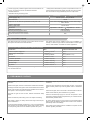 5
5
-
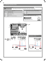 6
6
-
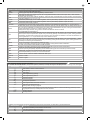 7
7
-
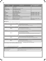 8
8
-
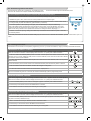 9
9
-
 10
10
-
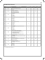 11
11
-
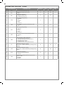 12
12
-
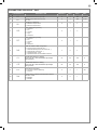 13
13
-
 14
14
-
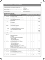 15
15
-
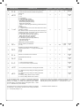 16
16
-
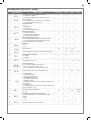 17
17
-
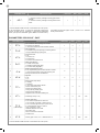 18
18
-
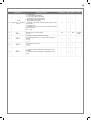 19
19
-
 20
20
-
 21
21
-
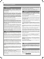 22
22
-
 23
23
-
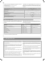 24
24
-
 25
25
-
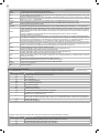 26
26
-
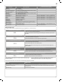 27
27
-
 28
28
-
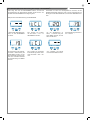 29
29
-
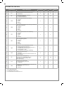 30
30
-
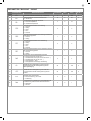 31
31
-
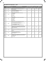 32
32
-
 33
33
-
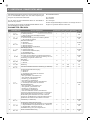 34
34
-
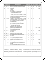 35
35
-
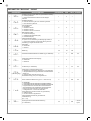 36
36
-
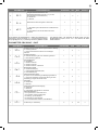 37
37
-
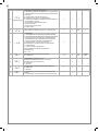 38
38
-
 39
39
-
 40
40
-
 41
41
-
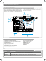 42
42
-
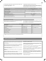 43
43
-
 44
44
-
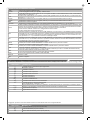 45
45
-
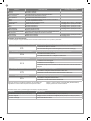 46
46
-
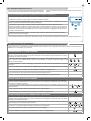 47
47
-
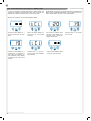 48
48
-
 49
49
-
 50
50
-
 51
51
-
 52
52
-
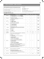 53
53
-
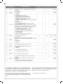 54
54
-
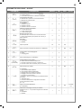 55
55
-
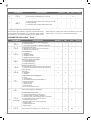 56
56
-
 57
57
-
 58
58
-
 59
59
-
 60
60
-
 61
61
-
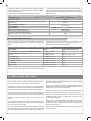 62
62
-
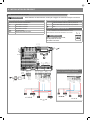 63
63
-
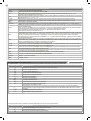 64
64
-
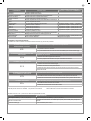 65
65
-
 66
66
-
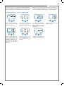 67
67
-
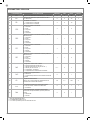 68
68
-
 69
69
-
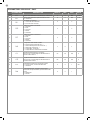 70
70
-
 71
71
-
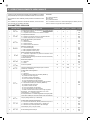 72
72
-
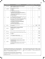 73
73
-
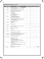 74
74
-
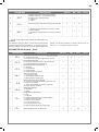 75
75
-
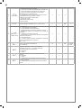 76
76
-
 77
77
-
 78
78
-
 79
79
-
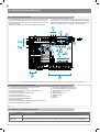 80
80
-
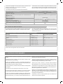 81
81
-
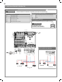 82
82
-
 83
83
-
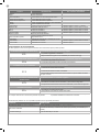 84
84
-
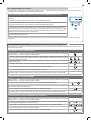 85
85
-
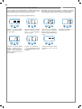 86
86
-
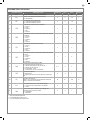 87
87
-
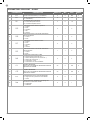 88
88
-
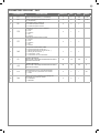 89
89
-
 90
90
-
 91
91
-
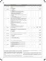 92
92
-
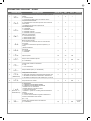 93
93
-
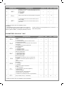 94
94
-
 95
95
-
 96
96
-
 97
97
-
 98
98
-
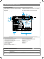 99
99
-
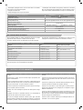 100
100
-
 101
101
-
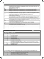 102
102
-
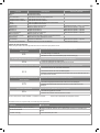 103
103
-
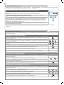 104
104
-
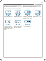 105
105
-
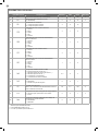 106
106
-
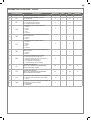 107
107
-
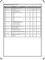 108
108
-
 109
109
-
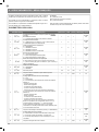 110
110
-
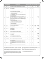 111
111
-
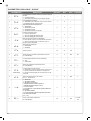 112
112
-
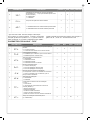 113
113
-
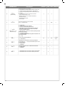 114
114
-
 115
115
-
 116
116
-
 117
117
-
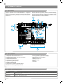 118
118
-
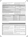 119
119
-
 120
120
-
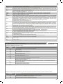 121
121
-
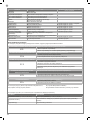 122
122
-
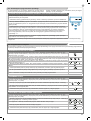 123
123
-
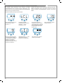 124
124
-
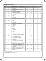 125
125
-
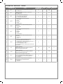 126
126
-
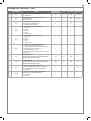 127
127
-
 128
128
-
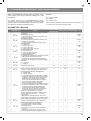 129
129
-
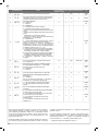 130
130
-
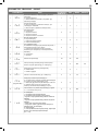 131
131
-
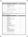 132
132
-
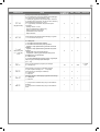 133
133
-
 134
134
-
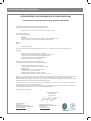 135
135
-
 136
136


Marantec CBX10224F El manual del propietario
- Tipo
- El manual del propietario
- Este manual también es adecuado para
en otros idiomas
- français: Marantec CBX10224F Le manuel du propriétaire
- italiano: Marantec CBX10224F Manuale del proprietario
- English: Marantec CBX10224F Owner's manual
- Deutsch: Marantec CBX10224F Bedienungsanleitung
- português: Marantec CBX10224F Manual do proprietário
- polski: Marantec CBX10224F Instrukcja obsługi
Artículos relacionados
-
Marantec CBX20224H El manual del propietario
-
-
-
-
-
-
Otros documentos
-
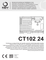 Key Automation 580ISCT10224 Manual de usuario
-
Key Gates CT10224 Manual de usuario
-
 Key Automation 580CT20324W Manual de usuario
-
 Key Automation CT202 24E Instructions And Warnings For Installation And Use
-
Key Gates CT102 Manual de usuario
-
-
-
 Key Automation 580STAR500W Manual de usuario
-
-
 Key Automation 580ISCT202 Manual de usuario


