SCOPREGA 6130650 Electric Inflator Manual de usuario
- Tipo
- Manual de usuario

1
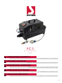
PCS
6130650
Pressure Control System
CONSERVARE QUESTE ISTRUZIONI
GONFIATORE ELETTRICOIT
SAVE THIS INSTRUCTIONS MANUAL FOR REFERENCE
ELECTRIC INFLATOREN
BITTE BEWAHREN SIE DIESE ANLEITUNG GUT AUF
ELEKTRISCHE LUFTPUMPEDE
CONSERVER CES INSTRUCTIONS
GONFLEUR ÉLECTRIQUEFR
CONSERVE ESTAS INSTRUCCIONES
INFLADOR ELÉCTRICOES

2
3
INDICE
1. DESCRIZIONE FUNZIONALE
2. PREMESSA
3. AVVERTENZE PRELIMINARI
4. REGOLE DI SICUREZZA GENERALI
5. INTRODUZIONE
6. DESCRIZIONE DEL GONFIATORE
7. DATI TECNICI
8. GONFIAGGIO: PCS
9. GONFIAGGIO: PCSIC INTERNAL CONTROL
10. SGONFIAGGIO - PCS E PCS-IC
11. RISOLUZIONE DEI PROBLEMI
11.1 AVVERTENZA SUGLI ACCESSORI
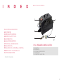
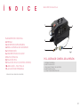
fig.1
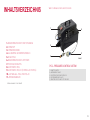
1. DESCRIZIONE FUNZIONALE
PCS - PRESSURE CONTROL SYSTEM
1. INTERRUTTORE GENERALE
2. BOCCA DI GONFIAGGIO
3. SENSORE ELETTRONICO DELLA PRESSIONE
4. BOCCA DI SGONFIAGGIO
5. SPINA SCHUKO INDUSTRIALE IP65
1
2
35
4

4
5
ISTRUZIONI
MANUALEDI
CONSERVARE QUESTE ISTRUZIONI
2. PREMESSA
Gentile cliente,
congratulazioni per aver scelto Scoprega.
Progettiamo e fabbrichiamo prodotti della massima qualità secondo le
esigenze della nostra clientela. Scoprega ore la massima qualità anche
nell’assistenza. I nostri uci dedicati garantiscono consulenza e istruzioni in
caso di bisogno, oltre a un’assistenza tecnica completa.
La ringraziamo per la fiducia.
7. ATTENZIONE! PERICOLO DI SCOPPIO.
Gonfiare l’unità gonfiabile solo seguendo le raccomandazioni del costruttore. Una pressione
eccessiva può causare l’esplosione del gonfiabile, che può cagionare lesioni personali.
8. NON LASCIARE MAI IL DISPOSITIVO SENZA SORVEGLIANZA.
Il gonfiaggio eccessivo può causare gravi lesioni e danni materiali.
9. ATTENZIONE! PERICOLO DI FUNZIONAMENTO NON SICURO
Non modificare o tentare di riparare l’unità. Non forare o apportare modifiche al gonfiatore o ai suoi
accessori. Qualunque modifica al prodotto comporta la decadenza della garanzia.
10. Non trasportare mai il gonfiatore dal tubo flessibile né dal cavo di alimentazione.
4. REGOLE DI SICUREZZA GENERALI
1. CONSIDERARE SEMPRE L’AMBIENTE DI LAVORO.
Non esporre il gonfiatore alla pioggia. Non utilizzare in presenza di liquidi o gas infiammabili.
2. EVITARE L’AVVIO ACCIDENTALE.
Non avviare il gonfiatore con la bocca di ingresso in contatto con polvere o acqua.
3. PRESTARE ATTENZIONE.
Prestare attenzione a quello che si sta facendo. Usare il buon senso.
4. CONTROLLARE CHE NON VI SIANO PARTI DANNEGGIATE.
Prima di usare il gonfiatore, ispezionare con attenzione le pareti esterne e i suoi componenti.
5. NON AVVIARE i gonfiatori portatili nei pressi di liquidi infiammabili o atmosfere gassose o
esplosive. I motori di questi gonfiatori producono scintille che possono rilasciare fumi.
6. ATTENZIONE A NON INALARE!
L’aria compressa proveniente dal gonfiatore non è pura. Non inalare mai aria dal gonfiatore.
Leggere queste istruzioni prima di utilizzare il gonfiatore. La mancata osservanza di
tutte le istruzioni elencate di seguito può provocare danni al prodotto e/o causare lesioni
gravi alle persone.
ATTENZIONE
NON ALIMENTARE IL GONFIATORE AD UNA
TENSIONE PIÙ ALTA DI QUELLA NOMINALE
1. Attenersi a tutte le istruzioni presenti su questo documento.
2. Conservare le presenti istruzioni.
3. Proteggere sempre il cavo di alimentazione.
4. Non aprire il gonfiatore. Far eseguire tutte le attività di manutenzione a manutentori qualificati
autorizzati da Scoprega. La manutenzione è necessaria quando l’apparecchio risulta in qualche
modo danneggiato o non funzionante.
5. Non manomettere il prodotto. L’apertura del gonfiatore comporta la decadenza della garanzia.
6. Fornire una ventilazione adeguata
7. Evitare di posizionare oggetti nelle vicinanze del prodotto durante il suo funzionamento.
8. Tenere il presente prodotto fuori dalla portata dei bambini.
9. Il gonfiatore in moto produce vibrazioni per cui, per evitare cadute accidentali, ne consigliamo
l’utilizzo a pavimento.
3. AVVERTENZE PRELIMINARI
5. INTRODUZIONE
Il sistema PCS è un gonfiatore in grado di mantenere la pressione nominale all’interno di grandi
strutture gonfiabili entro valori prefissati (min.90 mbar, max. 450 mbar), indipendentemente dalla
temperatura dell’ambiente. L’unità monitora costantemente la variazione di pressione all’interno
della struttura gonfiabile e ne regola il funzionamento per garantire il rabbocco e lo scarico della
pressione. In caso di temporanea mancanza di alimentazione, il sistema PCS mantiene tutti i valori
preimpostati e si riavvierà non appena la corrente sarà ripristinata.
Il sistema PCS (pressure control system) è un’unità in grado di gonfiare, mantenere una pressione
predefinita e sgonfiare una grande struttura gonfiabile. Questo significa che l’unità deve essere
sempre collegata al gonfiabile.
L’unità ha un grado di protezione IP65 che funziona anche in condizioni di pioggia o in presenza di
polvere.
Il sistema PCS viene fornito con adattatori da collegare alle piu’ comuni valvole di gonfiaggio
Il gonfiatore e’ dotato di un interruttore di sovraccarico termico che interviene in caso di
surriscaldamento. Il normale funzionamento riprenderà automaticamente dopo una pausa di
20/40 minuti
MODELLO PCS-IC (codice: K6130651)
Il modello PCS-IC è dierente rispetto al modello standard in quanto la pressione viene rilevata
da un sensore posto all’interno del gonfiatore stesso. Per cui, non dispone di sensore di pressione
e relativo cavo da collegare al gonfiabile. L’uso di questo modello è destinato al solo utilizzo di
tubi da 40mm di diametro con valvole adeguate (consigliata nostra BRAVO 260 H.V, codice:
A131000N)
*non presente su modello PCS-IC
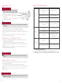
7. DATI TECNICI
1. Alimentazione
2. Potenza MAX
3. Range di pressione
4. Portata MAX
5. Dimensioni
6. Peso
7. Grado di protezione
8. Lunghezza del cavo di controllo pressione*
9. Pressione nominale
210-240 V AC, 50 Hz oppure 110-130 V AC, 60 Hz
2500 W
90-450 mbar (1.3-6.5 psi)
2800 l/min
700x250x h 350 mm
15 kg
IP65 - IEC 60529
10 metri
su richiesta (entro i limiti del range)
6. DESCRIZIONE DEL GONFIATORE

6
7
1. Collegare il tubo alla porta di sgonfiaggio (punto 4, figura a pag. 3) della PCS e alla valvola
principale della struttura gonfiabile
2. Collegare la spina di alimentazione a una presa idonea (punto 5, figura a pag. 3).
3. Accendere l’interruttore verde sul gonfiatore. La luce sull’interruttore si accenderà (punto 1, figura
a pag. 3).
4. 2 LED si accendono e dopo 4 secondi il LED rosso si spegne; il LED verde segnala che il PCS
inizierà a sgonfiare.
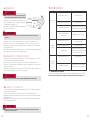
11. SOLUZIONE DEI PROBLEMI
PROBLEMA POSSIBILE CAUSA POSSIBILE SOLUZIONE
Il PCS non si
avvia
Gonfiatore
fermo
Interrutore principale VERDE spento
Cavo alimentazione non collegato
alla presa
Cavo di alimentazione danneggiato
Sensore di pressione non collegato
correttamente
Cavo alimentazione non
collegato alla presa
Interruttore principale spento
Sovra-temperatura
Premere l’interrutore
Collegarlo correttamente
far sostituire o riparare il cavo al
servizio assistenza SCOPREGA
Collegare il sensore di pressione
Collegarlo correttamente
Premere l’interruttore
Aspettare che i motori del PCS si
rareddino Il gonfiatore ripartirà
automaticamente.
LED VERDE
spento
Cavo alimentazione non collegato
alla presa
Cavo di alimentazione danneggiato
Collegarlo correttamente
far sostituire o riparare il cavo al
servizio assistenza SCOPREGA
Gli accessori raccomandati nell’utilizzo del gonfiatore sono quelli originali SCOPREGA.
L’uso di qualsiasi accessorio non raccomandato per questo gonfiatore può essere pericoloso.
11.1 AVVERTENZA SUGLI ACCESSORI
1. Collegare il tubo di gonfiaggio alla porta di uscita del PCS (punto 2, figura a pag. 3) e alla
valvola principale della struttura gonfiabile
2. Collegare la spina di alimentazione a una presa idonea (punto 5, figura a pag. 3)
3. Accendere l’interruttore verde sul gonfiatore (punto 1, figura a pag. 3). La luce sull’interruttore si
accenderà
4. 2 LED si accendono e dopo 4 secondi il LED rosso si spegne; il LED verde segnala che il PCS
inizierà a gonfiare alla pressione preimpostata.
9. GONFIAGGIO: PCSIC INTERNAL CONTROL
10. SGONFIAGGIO - PCS E PCS-IC
3. Collegare il cavo del sensore al connettore PCS (punto 3, figura a pag. 3)
4. Collegare la spina di alimentazione (punto 5, figura a pag. 3) a una presa idonea
5. Accendere l’interruttore verde sul gonfiatore (punto 1, figura a pag. 3). La luce sull’interruttore si
accenderà
6. 2 led si accendono e dopo 4 secondi il led rosso si spegne; il LED verde segnala che il PCS
inizierà a gonfiarsi alla pressione preimpostata.
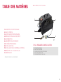
1. Collegare il tubo di gonfiaggio alla porta di uscita del
PCS (punto 2, figura a pag. 3) e alla valvola principale della
struttura gonfiabile
2. Collegare il cavo di controllo pressione con l’adattatore
alla valvola ausiliaria della struttura
CONTROLLARE CHE IL TUBO DI CONTROLLO DELLA PRESSIONE SIA
SEMPRE COLLEGATO AL GONFIATORE E ALLA STRUTTURA GONFIABILE
ATTENZIONE
fig.2
8. GONFIAGGIO: PCS
LA PRESSIONE DI GONFIAGGIO/CONTROLLO PUÒ ESSERE MODIFICATA SOLO PRESSO UN CENTRO ASSISTENZA
SCOPREGA
ATTENZIONE
ACCERTARSI CHE LA VALVOLA AUSILIARIA PER IL CONTROLLO DELLA PRESSIONE SIA IDONEA AL CONNETTORE DEL
SENSORE DELLA PCS
ATTENZIONE
LO SGONFIAGGIO NON SI ARRESTA AUTOMATICAMENTE. SPEGNERE IL GONFIATORE UNA VOLTA CHE IL GONFIABILE
VIENE SVUOTATO COMPLETAMENTE.
ATTENZIONE
INFLATING
TUBE
230V/120V
50Hz/60Hz
Pressure Sensor Cable

9
INDEX
1. FUNCTIONAL DESCRIPTION
2. FOREWORD
3. PRELIMINARY WARNINGS
4. GENERAL SAFETY RULES
5. INTRODUCTION
6. INFLATOR DESCRIPTION
7. TECHNICAL SPECIFICATIONS
8. INFLATION: PCS
9. INFLATION: PCSIC INTERNAL CONTROL
10. DEFLATION - PCS AND PCS-IC
11. TROUBLESHOOTING
11.1 ACCESSORY WARNING
fig.1
1. FUNCTIONAL DESCRIPTION
PCS - PRESSURE CONTROL SYSTEM
1. MAIN SWITCH
2. INFLATION PORT
3. ELECTRONIC PRESSURE SENSOR
4. DEFLATION PORT
5. IP65 INDUSTRIAL SHUCKO PLUG
1
2
35
4

10
11
MANUALOF
SAVE THIS INSTRUCTIONS MANUAL FOR REFERENCE
2. FOREWORD
Dear customer,
congratulations on choosing Scoprega.
We design and manufacture products of the highest quality to meet the needs
of our customers. Scoprega oers the highest quality in service as well. Our
specialised departments provide support and instructions when needed, as well
as comprehensive technical service.
We thank you for your trust.
4. GENERAL SAFETY RULES
1. ALWAYS TAKE INTO ACCOUNT THE WORKING ENVIRONMENT.
Do not expose the inflator to rain. Do not use in the presence of flammable liquids or gases.
2. AVOID UNINTENTIONAL STARTING.
Do not start the inflator with the inlet in contact with dust or water.
3. PAY ATTENTION.
Pay attention to what you are doing. Use common sense.
4. CHECK THAT THERE ARE NO DAMAGED PARTS.
Before using the inflator, carefully check its outer sides and components.
5. DO NOT OPERATE portable inflators near flammable liquids or in gaseous or explosive
atmospheres. The inflator motors produce sparks that can release fumes.
6. DO NOT INHALE!
The compressed air coming from the inflator is not clean. Never inhale air from your inflator.
Read these instructions before using the inflator. Failure to follow all the instructions listed
below may result in damage to the product and/or cause serious injury to persons.
WARNING
DO NOT POWER THE INFLATOR WITH A
VOLTAGE HIGHER THAN THE RATED ONE
1. Comply with all instructions in this document.
2. Keep these instructions.
3. Always protect the power cable.
4. Do not open the inflator. Refer all servicing to qualified service personnel authorised by Scoprega.
Servicing is required when the device is damaged or not working in any way.
5. Do not tamper with the product. Opening the inflator will void its warranty.
6. Provide suitable ventilation.
7. Avoid placing objects near the product during operation.
8. Keep this product out of the reach of children.
9. The operating inflator produces vibrations: therefore, we recommend you to use it on the floor, so as
to avoid accidental falls.
3. PRELIMINARY WARNINGS
INSTRUCTIONS
7. WARNING! RISK OF EXPLOSION.
Inflate the inflatable unit only complying with the manufacturer’s recommendations. Exceeding the
pressure rating could cause the inflator to explode, resulting in personal injury.
8. NEVER LEAVE THE DEVICE UNATTENDED.
Overinflation could result in serious injury and property damage.
9. WARNING! RISK OF UNSAFE OPERATION.
Do not modify or attempt to repair the unit. Do not drill into or make any modifications to the inflator
or its accessories. Any modification to the product will void its warranty.
10. Never carry the inflator by the flexible hose or power cable.
5. INTRODUCTION
The PCS system is a device capable of maintaining the rated pressure inside great inflatable items
within preset values (min.90 mbar, max. 450 mbar), regardless of ambient temperature. The unit
constantly monitors pressure variation inside the inflatable item and regulates its operation to ensure
refilling and release of pressure. In the event of a temporary power failure, the PCS system maintains all
preset values and will restart as soon as power is restored.
The PCS (pressure control system) is a unit capable of inflating, maintaining a preset pressure value
and deflating a large inflatable item. This means that the unit must always be connected to the
inflatable item.
The unit protection degree is IP65 and can be operated in rainy or dusty conditions.
The PCS is supplied with adapters to be connected to the most common inflation valves
The inflator is equipped with a thermal overload switch that trips in case of overheating. Normal
operation will restart automatically after a 20/40-minute pause
PCS-IC MODEL (code: K6130651)
The PCS-IC model diers from the standard model as pressure is detected
by a sensor inside the inflator itself. Therefore, it does not feature the pressure sensor
and the cable to be connected to the inflatable unit. This model is only intended for use with
40mm diameter hoses with suitable valves (we suggest our BRAVO 260 H.V, code:
A131000N)
*not provided on PCS-IC model
7. TECHNICAL SPECIFICATIONS
1. Power supply
2. MAX. power
3. Pressure range
4. MAX. flow rate
5. Dimensions
6. Weight
7. Protection degree
8. Pressure check cable length*
9. Rated pressure
210-240 V AC, 50 Hz or 110-130 V AC, 60 Hz
2500 W
90-450 mbar (1.3-6.5 psi)
2800 l/min
700x250x h 350 mm
15 kg
IP65 - IEC 60529
10 metres
on request (within range)
6. INFLATOR DESCRIPTION

12
13
1. Connect the hose to the PCS deflation port (point 4, figure on page 3) and to the main valve of the
inflatable item
2. Connect the power plug to a suitable socket (point 5, figure on page 3).
3. Switch on the green switch on the inflator. The light on the switch will light up (point 1, figure on page 3).
4. 2 LEDs light up and after 4 seconds the red LED turns o; the green LED indicates that the PCS will
automatically start to deflate.
1. Connect the inflation hose to the PCS outlet port (point 2, figure on page 3) and to the main valve
of the inflatable item
2. Connect the power plug to a suitable socket (point 5, figure on page 3)
3. Switch on the green switch on the inflator (point 1, figure on page 3). The light on the switch will light up
4. 2 LEDs light up and after 4 seconds the red LED turns o; the green LED indicates that the PCS will
automatically start to inflate to the set pressure.
9. INFLATION: PCSIC INTERNAL CONTROL
10. DEFLATION - PCS AND PCS-IC
3. Connect the sensor cable to the PCS connector (point 3, figure on page 3)
4. Connect the power plug (point 5, figure on page 3) to a suitable socket
5. Switch on the green switch on the inflator (point 1, figure on page 3). The light on the switch will light up
6. 2 LEDs light up and after 4 seconds the red LED turns o; the green LED indicates that the PCS will
automatically start to inflate to the set pressure.
1. Connect the inflation hose to the PCS outlet port (point 2,
figure on page 3) and to the main valve of the inflatable item
2. Connect the pressure control cable with the adapter to the
item auxiliary valve
CHECK THAT THE PRESSURE CONTROL HOSE IS ALWAYS CONNECTED TO
THE INFLATOR AND TO THE INFLATABLE ITEM
WARNING
fig.2
8. INFLATION: PCS
THE INFLATION/CHECK PRESSURE CAN ONLY BE CHANGED AT A SCOPREGA SERVICE CENTRE
WARNING
MAKE SURE THAT THE AUXILIARY VALVE FOR PRESSURE CHECK IS SUITABLE FOR THE PCS SENSOR CONNECTOR
WARNING
DEFLATION DOES NOT STOP AUTOMATICALLY. SWITCH OFF THE INFLATOR ONCE THE INFLATABLE UNIT IS COMPLETELY
EMPTIED.
WARNING
INFLATING
TUBE
230V/120V
50Hz/60Hz
Pressure Sensor Cable
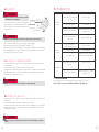
11. TROUBLESHOOTING
PROBLEM POSSIBLE CAUSE POSSIBLE SOLUTION
The PCS does
not start
The inflator is
stopped
The main GREEN switch is o
The power cable is not connected to
the socket
The power cable is damaged
Pressure sensor not properly
connected
The power cable is not
connected to the socket
The main switch is o
Over-temperature
Press the switch
Connect it correctly
Ask the SCOPREGA service to replace
or repair the cable
Connect the pressure sensor
Connect it correctly
Press the switch
Wait until the PCS motors cool down.
The inflator will restart automatically.
GREEN LED o
The power cable is not connected to
the socket
The power cable is damaged
Connect it correctly
Ask the SCOPREGA service to replace
or repair the cable
The recommended accessories when using the inflator are the original SCOPREGA ones.
The use of any accessory not recommended for this inflator can be dangerous.
11.1 ACCESSORY WARNING

15
INHALTSVERZEICHNIS
1. BESCHREIBUNG DER FUNKTIONSWEISE
2. VORWORT
3. VORWARNUNGEN
4. ALLGEMEINE SICHERHEITSREGELN
5. EINLEITUNG
6. BESCHREIBUNG DER LUFTPUMPE
7. TECHNISCHE DATEN
8. AUFPUMPEN: PCS
9. AUFPUMPEN: PCSIC INTERNAL CONTROL
10. LUFTABLASS - PCS UND PCS-IC
11. PROBLEMABHILFE
11.1 WARNHINWEIS ZUM ZUBEHÖR
Abb. 1
1. BESCHREIBUNG DER FUNKTIONSWEISE
PCS - PRESSURE CONTROL SYSTEM
1. HAUPTSCHALTER
2. AUFPUMPANSCHLUSS
3. ELEKTRONISCHER DRUCKSENSOR
4. ENTLEERUNGSANSCHLUSS
5. INDUSTRIELLER SCHUKOSTECKER IP65
1
2
35
4

16
17
BETRIEBSANLEITUNG
BITTE BEWAHREN SIE DIESE ANLEITUNG GUT AUF
2. VORWORT
Sehr geehrte Kundin, sehr geehrter Kunde,
herzlichen Glückwunsch zur Wahl von Scoprega.
Wir entwickeln und fertigen hochwertige Produkte, die den Bedürfnissen unserer
Kunden gerecht werden. Scoprega bietet auch einen hochqualitativen Kundendienst.
Unsere dafür zuständigen Abteilungen sichern Ihnen Beratung und vollständige
technische Unterstützung zu und geben im Bedarfsfall die erforderlichen Anweisungen.
Wir danken Ihnen für Ihr Vertrauen.
4. ALLGEMEINE SICHERHEITSREGELN
1. BERÜCKSICHTIGEN SIE IMMER DAS ARBEITSUMFELD.
Setzen Sie die Luftpumpe nie dem Regen aus. Nie bei Vorhandensein von entzündlichen Flüssigkeiten oder
Gasen verwenden.
2. VERMEIDEN SIE EIN UNBEABSICHTIGTES EINSCHALTEN.
Starten Sie die Luftpumpe nicht, wenn die Einlassönung mit Staub oder Wasser in Berührung kommt.
3. GEHEN SIE ACHTSAM VOR.
Üben Sie bei der Handhabung der Luftpumpe höchste Achtsamkeit. Verwenden Sie den
gesunden Menschenverstand.
4. ÜBERPRÜFEN SIE, DASS KEINE BESCHÄDIGTEN TEILE VORHANDEN SIND.
Prüfen Sie vor der Verwendung der Luftpumpe sorgfältig ihre Außenwände und Komponenten.
5. VERWENDEN Sie die tragbaren Luftpumpen nicht in der Nähe von entzündlichen Flüssigkeiten oder von
gashaltigen oder explosionsgefährdeten Atmosphären. Die Motoren dieser Luftpumpen erzeugen Funken,
die Rauch und Dämpfe entzünden können.
6. ACHTUNG, NICHT EINATMEN!
Die aus der Luftpumpe austretende Druckluft ist keine reine Luft. Atmen Sie nie die aus der Luftpumpe
austretende Luft ein.
Lesen Sie diese Anleitung vor der Verwendung der Luftpumpe. Die Nichtbeachtung
aller nachstehenden Anweisungen kann zu Schäden am Produkt und/oder zu schweren
Verletzungen von Personen führen.
ACHTUNG
VERSORGEN SIE DIE LUFTPUMPE NIE MIT EINER
SPANNUNG, DIE HÖHER ALS DIE NENNSPANNUNG IST
1. Befolgen Sie alle in diesem Dokument enthaltenen Anweisungen.
2. Bewahren Sie diese Anleitungen gut auf.
3. Schützen Sie stets das Netzkabel.
4. Önen Sie die Luftpumpe nie. Lassen Sie alle Wartungsarbeiten vom autorisierten, qualifizierten
Wartungspersonal von Scoprega ausführen. Die Wartung ist notwendig, wenn das Gerät in irgendeiner Weise
beschädigt ist oder nicht funktioniert.
5. Nehmen Sie keine Manipulationen am Produkt vor. Das Önen der Luftpumpe hat den Verfall der
Garantie zur Folge.
6. Gewährleisten Sie eine angemessene Belüftung
7. Vermeiden Sie es Gegenstände in der Nähe des Produkts abzustellen, während es in Betrieb steht.
8. Bewahren Sie das Produkt außerhalb der Reichweite von Kindern auf.
9. Die laufende Luftpumpe erzeugt Vibrationen. Um zu verhindern, dass sie herunterfällt, empfehlen wir sie
am Boden stehend zu verwenden.
3. VORWARNUNGEN
ANLEITUNG
7. ACHTUNG! BERSTGEFAHR.
Befüllen Sie den aufblasbaren Gegenstand ausschließlich gemäß den Herstellerempfehlungen. Ein
übermäßiger Druck kann zum Bersten des aufblasbaren Gegenstands und damit einhergehend zu
Verletzungen von Personen führen.
8. LASSEN SIE DAS GERÄT NIEMALS UNBEAUFSICHTIGT.
Übermäßiges Befüllen kann zu schweren Verletzungen und Sachschäden führen.
9. ACHTUNG! GEFAHR EINER UNSICHEREN FUNKTIONSWEISE
Nehmen Sie keine Änderungen oder Reparaturversuche vor. Bohren Sie die Luftpumpe nicht an und nehmen
Sie keine Änderungen daran oder an ihrem Zubehör vor. Jede Änderung am Produkt hat den Verfall der
Garantie zur Folge.
10. Transportieren Sie die Luftpumpe niemals am Schlauch oder am Netzkabel.
5. EINLEITUNG
Das mit PCS bezeichnete System ist eine Luftpumpe, die den Nenndruck in großen aufblasbaren
Produkten unabhängig von der Umgebungstemperatur innerhalb der voreingestellten Werte (min. 90
mbar, max. 450 mbar) zu halten in der Lage ist. Das Gerät hält die Druckschwankungen innerhalb der
Struktur ständig unter Kontrolle und regelt den Betrieb so, dass Druck nachgefüllt oder abgelassen
wird. Bei zeitweisem Ausfall der Versorgung hält das PCS alle voreingestellten Werte bei und wird erneut
anlaufen, sobald die Stromversorgung wieder gegeben ist.
Das PCS (Pressure Control System) ist eine Einheit, die in der Lage ist, eine große aufblasbare Struktur
aufzublasen, einen vorgegebenen Druck aufrecht zu erhalten und die Luft abzulassen. Das bedeutet,
dass das Gerät immer mit dem aufblasbaren Gegenstand verbunden sein muss.
Das Gerät ist mit der Schutzart IP65 klassifiziert, d.h. es funktioniert auch bei Regen oder Staub.
Das PCS wird mit Adaptern zum Anschluss an die gängigsten Füllventile geliefert.
Die Luftpumpe ist mit einem thermischen Überlastungsschalter ausgestattet, der bei einer
Überhitzung anspricht. Der normale Betrieb wird nach einer Pause von 20/40 Minuten automatisch
wieder aufgenommen.
MODELL PCS-IC (Artikelnummer: K6130651)
Das Modell PCS-IC unterscheidet sich vom Standardmodell dadurch, dass der Druck
von einem Sensor in der Luftpumpe erfasst wird. Daher verfügt sie über keinen Drucksensor
und ihr Kabel muss an den aufblasbaren Gegenstand angeschlossen werden. Dieses Modell ist nur für
die Verwendung mit
Schläuchen mit einem Durchmesser von 40 mm und passenden Ventilen bestimmt (unsere BRAVO
260 H.V, Artikelnummer:
A131000N)
*am PCS-IC nicht vorhanden
7. TECHNISCHE DATEN
1. Stromversorgung
2. MAX. Leistung
3. Druckbereich
4. MAX. Durchsatz
5. Abmessungen
6. Gewicht
7. Schutzart
8. Länge des Druckkontrollkabels*
9. Nenndruck
210-240 V AC, 50 Hz oder 110-130 V AC, 60 Hz
2500 W
90-450 mbar (1.3-6.5 psi)
2800 l/min
700x250x h 350 mm
15 kg
IP65 - IEC 60529
10 Meter
auf Anfrage (innerhalb der Bereichsgrenzwerte)
6. BESCHREIBUNG DER LUFTPUMPE

18
19
1. Schließen Sie den Ablassschlauch (Punkt 4, Abbildung auf Seite 3) des PCS und an das Hauptventil
des aufblasbaren Gegenstands an
2. Stecken Sie den Stromstecker in eine geeignete Steckdose (Punkt 5, Abbildung auf Seite 3).
3. Den grünen Schalter an der Luftpumpe einschalten. Das Licht des Schalters wird aufleuchten (Punkt 1,
Abbildung auf Seite 3).
4. Die 2 LEDs leuchten und nach 4 Sekunden erlischt die rote LED; die grüne LED weist darauf hin, dass
das PCS mit dem Ablass beginnt.
1. Schließen Sie den Luftschlauch an den Ausgang des PCS (Punkt 2 der Abbildung auf Seite 3) und
an das Hauptventil des aufblasbaren Gegenstands an
2. Stecken Sie den Stromstecker in eine geeignete Steckdose (Punkt 5, Abbildung auf Seite 3).
3. Schalten Sie den grünen Schalter der Luftpumpe ein (Punkt 1, Abbildung auf Seite 3). Das Licht des
Schalters wird aufleuchten.
4. Die 2 LEDs leuchten und nach 4 Sekunden erlischt die rote LED; die grüne LED weist darauf hin, dass
das PCS mit dem Füllen bis auf den eingestellten Druck beginnt.
9. AUFPUMPEN: PCSIC INTERNAL CONTROL
10. LUFTABLASS - PCS UND PCS-IC
3. Schließen Sie das Sensorkabel an den Anschluss des PCS an (Punkt 3, Abbildung auf Seite 3).
4. Stecken Sie den Stromstecker (Punkt 5, Abbildung auf Seite 3) in eine geeignete Steckdose ein.
5. Schalten Sie den grünen Schalter der Luftpumpe ein (Punkt 1, Abbildung auf Seite 3). Das Licht des
Schalters wird aufleuchten.
6. Die 2 LEDs leuchten und nach 4 Sekunden erlischt die rote LED; die grüne LED weist darauf hin, dass
das PCS mit dem Füllen bis auf den eingestellten Druck beginnt.
1. Schließen Sie den Luftschlauch an den Ausgang des PCS
(Punkt 2 der Abbildung auf Seite 3) und an das Hauptventil
des aufblasbaren Gegenstands an
2. Schließen Sie das Druckkontrollkabel mit dem Adapter an
das Hilfsventil der Struktur an
KONTROLLIEREN SIE, DASS DER DRUCKKONTROLLSCHLAUCH STETS MIT
DER LUFTPUMPE UND DEM AUFBLASBAREN GEGENSTAND VERBUNDEN IST
ACHTUNG
Abb. 2
8. AUFPUMPEN: PCS
DER FÜLL-/KONTROLLDRUCK KANN NUR IN EINEM SCOPREGA KUNDENDIENSTZENTRUM GEÄNDERT WERDEN
ACHTUNG
STELLEN SIE SICHER, DASS DAS HILFSVENTIL FÜR DIE DRUCKREGELUNG FÜR DEN STECKER DES SENSORS DES PCS
GEEIGNET IST.
ACHTUNG
DIE ABLASSFUNKTION STOPPT NICHT AUTOMATISCH. SCHALTEN SIE DIE LUFTPUMPE AUS, WENN DER AUFBLASBARE
GEGENSTAND VOLLSTÄNDIG ENTLEERT IST.
ACHTUNG
INFLATING
TUBE
230 V/120 V
50 Hz/60 Hz
Pressure Sensor Cable
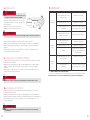
11. PROBLEMABHILFE
PROBLEM MÖGLICHE URSACHE MÖGLICHE ABHILFE
Das PCS startet
nicht
Luftpumpe
gestoppt
Hauptschalter GRÜN erloschen
Netzkabel nicht eingesteckt
Beschädigtes Netzkabel
Drucksensor nicht richtig
angeschlossen
Netzkabel nicht eingesteckt
Hauptschalter ausgeschaltet
Übertemperatur
Den Schalter drücken
Richtig anschließen
Lassen Sie das Kabel vom SCOPREGA
Kundendienst wechseln oder reparieren
Den Drucksensor anschließen
Richtig anschließen
Den Schalter drücken
Warten, bis die Motoren des PCS
abgekühlt sind. Die Luftpumpe wird dann
automatisch wieder starten.
GRÜNE LED
erloschen
Netzkabel nicht eingesteckt
Beschädigtes Netzkabel
Richtig anschließen
Lassen Sie das Kabel vom SCOPREGA
Kundendienst wechseln oder reparieren
Das für die Verwendung der Luftpumpe empfohlene Zubehör ist das Original-Zubehör von SCOPREGA.
Das Verwenden von nicht für diese Luftpumpe empfohlenem Zubehör kann gefährlich sein.
11.1 WARNHINWEIS ZUM ZUBEHÖR

21
TABLE DES MATIÈRES
1. DESCRIPTION FONCTIONNELLE
2. AVANT-PROPOS
3. AVERTISSEMENTS PRÉLIMINAIRES
4. RÈGLES GÉNÉRALES DE SÉCURITÉ
5. INTRODUCTION
6. DESCRIPTION DU GONFLEUR
7. DONNÉES TECHNIQUES
8. GONFLAGE: PCS
9. GONFLAGE: PCSIC INTERNAL CONTROL
10. DÉGONFLAGE - PCS ET PCS-IC
11. DÉPANNAGE
11.1 AVERTISSEMENT SUR LES ACCESSOIRES
fig.1
1. DESCRIPTION FONCTIONNELLE
PCS - PRESSURE CONTROL SYSTEM
1. INTERRUPTEUR GÉNÉRAL
2. BOUCHE DE GONFLAGE
3. CAPTEUR DE PRESSION ÉLECTRONIQUE
4. BOUCHE DE DÉGONFLAGE
5. FICHE INDUSTRIELLE SCHUKO IP65
1
2
35
4

22
23
MANUELD’
CONSERVER CES INSTRUCTIONS
2. AVANT-PROPOS
Cher client,
félicitations pour avoir choisi Scoprega.
Nous concevons et fabriquons des produits de qualité supérieure qui répondent
aux besoins de nos clients. Scoprega ore également un service d’assistance
de la plus haute qualité. Nos bureaux dédiés vous fournissent tous conseils et
instructions au besoin, en plus d’un service complet d’assistance technique.
Nous vous remercions de votre confiance.
4. RÈGLES GÉNÉRALES DE SÉCURITÉ
1. TOUJOURS CONSIDÉRER L’ENVIRONNEMENT DE TRAVAIL.
Ne pas exposer le gonfleur à la pluie. Ne pas utiliser en présence de liquides ou de gaz inflammables.
2. ÉVITER TOUT DÉMARRAGE ACCIDENTEL.
Ne pas démarrer le gonfleur avec la bouche d’entrée en contact avec de la poussière ou de l’eau.
3. FAIRE ATTENTION.
Faire attention aux gestes eectués. Faire preuve de bon sens.
4. VÉRIFIER QU’IL N’Y A AUCUNE PIÈCE ENDOMMAGÉE.
Avant d'utiliser le gonfleur, examiner attentivement les parois extérieures et les composants.
5. NE PAS DÉMARRER les gonfleurs portables à proximité de liquides inflammables ou
d’atmosphères gazeuses ou explosives. Les moteurs de ces gonfleurs produisent des étincelles qui
peuvent libérer des fumées.
6. VEILLER À NE PAS INHALER!
L’air comprimé du gonfleur n’est pas pur. Ne jamais inhaler l'air provenant du gonfleur.
Lire ces instructions avant d’utiliser le gonfleur. Le non-respect de l’ensemble des instructions
énumérées ci-dessous peut endommager le produit et/ou causer des blessures graves.
ATTENTION
NE PAS ALIMENTER LE GONFLEUR À UNE
TENSION SUPÉRIEURE À CELLE NOMINALE
1. Suivre toutes les instructions de ce document.
2. Conserver ces instructions.
3. Toujours protéger le câble d'alimentation.
4. Ne pas ouvrir le gonfleur. Tout entretien doit être eectué par du personnel d'entretien qualifié et
autorisé par Scoprega. L'entretien est nécessaire lorsque l’appareil est endommagé de quelque façon
que ce soit ou ne fonctionne pas.
5. Ne pas altérer le produit. L'ouverture du gonfleur annule la garantie.
6. Fournir une ventilation adéquate.
7. Éviter de placer des objets à proximité du produit pendant son fonctionnement.
8. Garder ce produit hors de portée des enfants.
9. Le gonfleur en mouvement produit des vibrations; pour éviter les chutes accidentelles, nous
recommandons de l'utiliser sur le sol.
3. AVERTISSEMENTS PRÉLIMINAIRES
INSTRUCTIONS
7. ATTENTION! DANGER D'ÉCLATEMENT.
Ne gonfler l'unité gonflable que conformément aux recommandations du fabricant. Une pression
excessive peut provoquer l'explosion du gonflable, ce qui peut entraîner des blessures corporelles.
8. NE JAMAIS LAISSER LE DISPOSITIF SANS SURVEILLANCE.
Le surgonflage peut provoquer des blessures graves et des dommages matériels.
9. ATTENTION! DANGER DE FONCTIONNEMENT NON SÛR
Ne pas modifier ou tenter de réparer l'unité. Ne pas percer ou modifier le gonfleur ou ses accessoires.
Toute modification du produit annule la garantie.
10. Ne jamais transporter le gonfleur par le tuyau flexible ou le câble d'alimentation.
5. INTRODUCTION
Le système PCS est un gonfleur capable de maintenir la pression nominale à l'intérieur de grandes
structures gonflables dans des valeurs prédéfinies (min. 90 mbar, max. 450 mbar), indépendamment
de la température ambiante. L'unité surveille en permanence la variation de pression à l'intérieur de
la structure gonflable et régule son fonctionnement pour assurer le remplissage et la libération de la
pression. En cas de panne de courant temporaire, le système PCS conserve toutes les valeurs prédéfinies
et redémarre dès que le courant est rétabli.
Le système PCS (pressure control system) est une unité capable de gonfler, de maintenir une pression
prédéfinie et de dégonfler une grande structure gonflable. Cela signifie que l'unité doit toujours être
connectée au gonflable.
L'unité a un degré de protection IP65, ce qui signifie qu'elle fonctionne même dans des conditions
pluvieuses ou poussiéreuses.
Le système PCS est fourni avec des adaptateurs pour se connecter aux vannes de gonflage les plus
courantes.
Le gonfleur est équipé d'un interrupteur de surcharge thermique qui se déclenche en cas de surchaue.
Le fonctionnement normal sera rétabli automatiquement après une pause de 20/40 minutes.
MODÈLE PCS-IC (code: K6130651)
Le modèle PCS-IC dière du modèle standard en ce que la pression est détectée
par un capteur placé à l'intérieur du gonfleur lui-même. Il ne dispose donc pas d'un capteur de pression
et d'un câble correspondant à connecter au gonflable. L'utilisation de ce modèle n'est prévue que
pour des tuyaux de 40 mm de diamètre avec des vannes appropriées (notre BRAVO 260 H.V. est
recommandée, code:
A131000N)
*non présent sur le modèle PCS-IC
7. DONNÉES TECHNIQUES
1. Alimentation
2. Puissance MAXI
3. Plage de pression
4. Débit MAXI
5. Dimensions
6. Poids
7. Degré de protection
8. Longueur du câble de contrôle de la pression*
9. Pression nominale
210-240 V CA, 50 Hz ou 110-130 V CA, 60 Hz
2500 W
90-450 mbar (1.3-6.5 psi)
2800 l/min
700x250x h 350 mm
15 kg
IP65 - IEC 60529
10 mètres
sur demande (dans les limites de la plage)
6. DESCRIPTION DU GONFLEUR

24
25
1. Brancher le tuyau à l'orifice de dégonflage (point 4, figure de la page 3) du PCS et à la vanne
principale de la structure gonflable
2. Brancher la fiche d'alimentation sur une prise de courant appropriée (point 5, figure de la page 3).
3. Allumer l'interrupteur vert du gonfleur. La lumière sur l'interrupteur s'allumera (point 1, figure de la page 3).
4. 2 LED s'allument et, après 4 secondes, la LED rouge s'éteint; la LED verte indique que le PCS va
commencer à dégonfler.
1. Brancher le tuyau de gonflage à l'orifice de sortie du PCS (point 2, figure de la page 3) et à la vanne
principale de la structure gonflable
2. Brancher la fiche d'alimentation sur une prise de courant appropriée (point 5, figure de la page 3)
3. Allumer l'interrupteur vert du gonfleur (point 1, figure de la page 3). La lumière de l'interrupteur
s'allumera
4. 2 LED s'allument et, après 4 secondes, la LED rouge s'éteint; la LED verte indique que le PCS va
commencer à gonfler à la pression prédéfinie.
9. GONFLAGE: PCSIC INTERNAL CONTROL
10. DÉGONFLAGE - PCS ET PCS-IC
3. Brancher le câble du capteur au connecteur PCS (point 3, figure de la page 3)
4. Brancher la fiche d'alimentation (point 5, figure de la page 3) sur une prise de courant appropriée
5. Allumer l'interrupteur vert du gonfleur (point 1, figure de la page 3). La lumière de l'interrupteur
s'allumera
6. 2 LED s'allument et, après 4 secondes, la LED rouge s'éteint; la LED verte indique que le PCS va
commencer à gonfler à la pression prédéfinie.
1. Brancher le tuyau de gonflage à l'orifice de sortie du PCS
(point 2, figure de la page 3) et à la vanne principale de la
structure gonflable
2. Brancher le câble de contrôle de la pression avec
l'adaptateur sur la vanne auxiliaire de la structure
VÉRIFIER QUE LE TUYAU DE CONTRÔLE DE LA PRESSION EST TOUJOURS
RACCORDÉ AU GONFLEUR ET À LA STRUCTURE GONFLABLE.
ATTENTION
fig.2
8. GONFLAGE: PCS
LA PRESSION DE GONFLAGE/CONTRÔLE NE PEUT ÊTRE MODIFIÉE QUE DANS UN CENTRE DE SERVICE SCOPREGA
ATTENTION
S'ASSURER QUE LA VANNE DE CONTRÔLE DE LA PRESSION AUXILIAIRE S'ADAPTE AU CONNECTEUR DU CAPTEUR DU PCS
ATTENTION
LE DÉGONFLAGE NE S'ARRÊTE PAS AUTOMATIQUEMENT. ARRÊTER LE GONFLEUR UNE FOIS QUE LE GONFLABLE EST
COMPLÈTEMENT VIDÉ.
ATTENTION
INFLATING
TUBE
230V/120V
50Hz/60Hz
Pressure Sensor Cable
11. DÉPANNAGE
PROBLÈME CAUSE POSSIBLE SOLUTION POSSIBLE
Le PCS ne
démarre pas
Le gonfleur est
arrêté
L’interrupteur principal VERT est éteint
Le câble d’alimentation n’est pas
branché à la prise
Le câble d'alimentation est
endommagé
Le capteur de pression n’est pas
branché correctement
Le câble d’alimentation n’est
pas branché à la prise
L’interrupteur principal est éteint
Surchaue
Appuyer sur l’interrupteur
Le brancher correctement
Le câble doit être remplacé ou réparé
par le service après-vente SCOPREGA
Brancher le capteur de pression
Le brancher correctement
Appuyer sur l’interrupteur
Attendre que les moteurs du PCS
refroidissent et le gonfleur redémarrera
automatiquement.
LED VERTE
éteinte
Le câble d’alimentation n’est pas
branché à la prise
Le câble d'alimentation est
endommagé
Le brancher correctement
Le câble doit être remplacé ou réparé
par le service après-vente SCOPREGA
Les accessoires recommandés lors de l'utilisation du gonfleur sont les accessoires d’origine SCOPREGA.
L’utilisation de tout accessoire non recommandé pour ce gonfleur peut être dangereuse.
11.1 AVERTISSEMENT SUR LES ACCESSOIRES

27
ÍNDICE
1. DESCRIPCIÓN FUNCIONAL
2. PREMISA
3. ADVERTENCIAS PRELIMINARES
4. REGLAS GENERALES DE SEGURIDAD
5. INTRODUCCIÓN
6. DESCRIPCIÓN DEL INFLADOR
7. DATOS TÉCNICOS
8. INFLACIÓN: PCS
9. INFLACIÓN: PCSIC CONTROL INTERNO
10. DEFLACIÓN - PCS Y PCS-IC
11. SOLUCIÓN DE PROBLEMAS
11.1 ADVERTENCIA SOBRE LOS ACCESORIOS
fig.1
1. DESCRIPCIÓN FUNCIONAL
PCS - SISTEMA DE CONTROL DE LA PRESIÓN
1. INTERRUPTOR GENERAL
2. PUERTO DE INFLACIÓN
3. SENSOR ELECTRÓNICO DE LA PRESIÓN
4. PUERTO DE DEFLACIÓN
5. CLAVIJA SCHUKO INDUSTRIAL IP65
1
2
35
4

28
29
MANUAL DE
CONSERVE ESTAS INSTRUCCIONES
2. PREMISA
Estimado cliente:
Felicitaciones por elegir Scoprega.
Diseñamos y fabricamos productos de máxima calidad según las exigencias de
nuestros clientes. Scoprega ofrece la máxima calidad también en la asistencia.
Nuestras oficinas específicas garantizan asesoramiento e instrucciones en caso
de necesidad, así como una completa asistencia técnica.
Le agradecemos por la confianza manifestada.
4. REGLAS GENERALES DE SEGURIDAD
1. CONSIDERE SIEMPRE EL ENTORNO DE TRABAJO.
No exponga el inflador a la lluvia. No utilice en presencia de líquidos o gases inflamables.
2. EVITE LA PUESTA EN MARCHA ACCIDENTAL.
No encienda el inflador con el puerto de entrada en contacto con polvo o agua.
3. PRESTE ATENCIÓN.
Preste atención a lo que está haciendo. Use el sentido común.
4. COMPRUEBE QUE NO HAYA PIEZAS DAÑADAS.
Antes de usar el inflador, inspeccione atentamente las paredes externas y sus componentes.
5. NO PONGA EN MARCHA los infladores portátiles en proximidad de líquidos inflamables o
atmósferas gaseosas o explosivas. Los motores de estos infladores producen chispas que pueden
generar humo.
6. ¡NO INHALAR!
El aire comprimido que sale del inflador no es puro. No inhalar nunca aire del inflador.
Lea estas instrucciones antes de utilizar el inflador. El incumplimiento de las instrucciones
mencionadas a continuación podría resultar en daños al producto y/o causar lesiones graves.
ATENCIÓN
NO ALIMENTAR EL INFLADOR A UNA
TENSIÓN SUPERIOR A LA NOMINAL
1. Respete todas las instrucciones presentes en este documento.
2. Conserve las presentes instrucciones.
3. Proteja siempre el cable de alimentación.
4. No abra el inflador. Asegúrese de que todas las actividades de mantenimiento sean efectuadas por
personal de mantenimiento cualificados autorizados por Scoprega. El mantenimiento es necesario
cuando el dispositivo resulta dañado en alguna medida o no funciona.
5. No altere el producto. La apertura del inflador implica la nulidad de la garantía.
6. Asegúrese de proporcionar una ventilación adecuada
7. Evite colocar objetos en proximidad del producto durante su funcionamiento.
8. Mantenga el presente dispositivo fuera del alcance de los niños.
9. El inflador en movimiento produce vibraciones por tanto, para evitar caídas accidentales,
recomendamos el uso en el suelo.
3. ADVERTENCIAS PRELIMINARES
INSTRUCCIONES
7. ¡ATENCIÓN! PELIGRO DE EXPLOSIÓN.
Infle la unidad hinchable solo siguiendo las recomendaciones del fabricante. Una presión excesiva
puede causar la explosión del hinchable, provocando lesiones personales.
8. NO DEJE NUNCA EL DISPOSITIVO SIN LA SUPERVISIÓN DE ALGUIEN.
Una inflación excesiva puede provocar graves lesiones y daños materiales.
9. ¡ATENCIÓN! PELIGRO DE FUNCIONAMIENTO NO SEGURO
No modifique ni intente reparar la unidad. No perfore ni efectúe modificaciones al inflador o a sus
accesorios. Cualquier modificación al producto implica la nulidad de la garantía.
10. No trasporte nunca el inflador del tubo flexible ni del cable de alimentación.
5. INTRODUCCIÓN
El sistema PCS es un inflador que mantiene la presión nominal dentro de grandes estructuras
hinchables en valores determinados (mín.90 mbar, máx. 450 mbar), independientemente de la
temperatura del ambiente. La unidad monitoriza constantemente la variación de presión dentro
de la estructura hinchable y regula el funcionamiento para garantizar el llenado y la descarga de la
presión. En caso de ausencia temporal de alimentación, el sistema PCS mantiene todos los valores ya
programados y reiniciará en cuanto se restablezca la corriente.
El sistema PCS (sistema de control de la presión) es una unidad que puede inflar, mantener una
presión determinada y desinflar una gran estructura hinchable. Esto significa que la unidad debe
estar siempre conectada al hinchable.
La unidad tiene un grado de protección IP65 que funciona también en condiciones de lluvia o en
presencia de polvo.
El sistema PCS se suministra con adaptadores para conectar a las válvulas más comunes de inflación
El inflador está dotado de un interruptor de sobrecarga térmica que interviene en caso de
sobrecalentamiento. El funcionamiento normal retomará automáticamente después de una pausa
de 20/40 minutos
MODELO PCS-IC (código: K6130651)
El modelo PCS-IC es diferente con respecto al modelo estándar ya que la presión es detectada
por un sensor presente dentro del mismo inflador. Por tanto, no dispone de sensor de presión
ni relativo cable para conectar al hinchable. El uso de este modelo está destinado solo al empleo de
tubos de 40 mm de diámetro con válvulas adecuadas (se recomienda nuestra BRAVO 260 H.V, código:
A131000N)
*no presente en el modelo PCS-IC
7. DATOS TÉCNICOS
1. Alimentación
2. Potencia MÁX.
3. Rango de presión
4. Capacidad MÁX.
5. Dimensiones
6. Peso
7. Grado de protección
8. Longitud del cable de control presión*
9. Presión nominal
210-240 V AC, 50 Hz o 110-130 V AC, 60 Hz
2500 W
90-450 mbar (1.3-6.5 psi)
2800 l/min
700x250x h 350 mm
15 kg
IP65 - IEC 60529
10 metros
a petición (dentro de los límites del rango)
6. DESCRIPCIÓN DEL INFLADOR

30
31
1. Conectar el tubo al puerto de deflación (punto 4, figura en pág. 3) del PCS y a la válvula principal de
la estructura hinchable
2. Conectar la clavija de alimentación a una toma idónea (punto 5, figura en pág. 3).
3. Encender el interruptor verde del inflador. La luz del interruptor se encenderá (punto 1, figura en pág. 3).
4. Los 2 LED se encienden y después de 4 segundos el LED rojo se apaga; el LED verde indica que el
PCS comenzará a desinflar.
1. Conectar el tubo de inflación a la puerto de salida del PCS (punto 2, figura en pág. 3) y a la válvula
principal de la estructura hinchable
2. Conectar la clavija de alimentación a una toma idónea (punto 5, figura en pág. 3)
3. Encender el interruptor verde del inflador (punto 1, figura en pág. 3). La luz del interruptor se
encenderá
4. Los 2 LED se encienden y después de 4 segundos el LED rojo se apaga; el LED verde indica que el
PCS comenzará a inflar con la presión ya programada.
9. INFLACIÓN: PCSIC CONTROL INTERNO
10. DEFLACIÓN - PCS Y PCS-IC
3. Conectar el cable del sensor al conector PCS (punto 3, figura en pág. 3)
4. Conectar la clavija de alimentación (punto 5, figura en pág. 3) a una toma adecuada
5. Encender el interruptor verde del inflador (punto 1, figura en pág. 3). La luz del interruptor se encenderá
6. Los 2 led se encienden y después de 4 segundos el led rojo se apaga; el LED verde indica que el PCS
comenzará a inflar a la presión ya programada.
1. Conectar el tubo de inflación a la puerto de salida del
PCS (punto 2, figura en pág. 3) y a la válvula principal de la
estructura hinchable
2. Conectar el cable de control presión con el adaptador a la
válvula auxiliar de la estructura
VERIFIQUE QUE EL TUBO DE CONTROL DE LA PRESIÓN ESTÉ SIEMPRE
CONECTADO AL INFLADOR Y A LA ESTRUCTURA HINCHABLE
ATENCIÓN
fig.2
8. INFLACIÓN: PCS
LA PRESIÓN DE INFLACIÓN/CONTROL PUEDE SER MODIFICADA SOLO EN UN CENTRO DE ASISTENCIA SCOPREGA
ATENCIÓN
ASEGURARSE DE QUE LA VÁLVULA AUXILIAR PARA EL CONTROL DE LA PRESIÓN SEA IDÓNEA PARA EL CONECTOR DEL
SENSOR DEL PCS
ATENCIÓN
LA DEFLACIÓN NO SE DETIENE AUTOMÁTICAMENTE. APAGAR EL INFLADOR DESPUÉS DE QUE EL HINCHABLE SE VACÍA
COMPLETAMENTE.
ATENCIÓN
INFLATING
TUBE
230V/120V
50Hz/60Hz
Cable Sensor de Presión
11. SOLUCIÓN DE PROBLEMAS
PROBLEMA POSIBLE CAUSA SOLUCIÓN POSIBLE
El PCS no
se pone en
marcha
Inflador
detenido
Interruptor principal VERDE apagado
El cable de alimentación no está
conectado a la toma
Cable de alimentación dañado
Sensor de presión no conectado
correctamente
El cable de alimentación no
está conectado a la toma
Interruptor principal apagado
Sobretemperatura
Presionar el interruptor
Conectarlo correctamente
hacer sustituir o reparar el cable al
servicio de asistencia SCOPREGA
Conectar el sensor de presión
Conectarlo correctamente
Presionar el interruptor
Esperar a que los motores del PCS
se enfríen. El inflador retomará el
funcionamiento automáticamente.
LED VERDE
apagado
El cable de alimentación no está
conectado a la toma
Cable de alimentación dañado
Conectarlo correctamente
hacer sustituir o reparar el cable al
servicio de asistencia SCOPREGA
Los accesorios recomendados para el uso del inflador son los originales SCOPREGA.
El uso de cualquier accesorio no recomendado para este inflador puede resultar peligroso.
11.1 ADVERTENCIA SOBRE LOS ACCESORIOS
-
 1
1
-
 2
2
-
 3
3
-
 4
4
-
 5
5
-
 6
6
-
 7
7
-
 8
8
-
 9
9
-
 10
10
-
 11
11
-
 12
12
-
 13
13
-
 14
14
-
 15
15
-
 16
16


SCOPREGA 6130650 Electric Inflator Manual de usuario
- Tipo
- Manual de usuario
en otros idiomas
Artículos relacionados
-
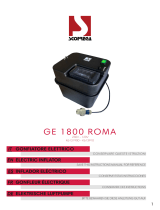 SCOPREGA GE 1800 ROMA Manual de usuario
-
 SCOPREGA GE2000 ARS Electric Inflator Manual de usuario
-
 SCOPREGA GE 22 RC Electronic Inflator Remote Compressor Guía de instalación
-
SCOPREGA G E BTP-2 Manual de usuario
-
 SCOPREGA GE20-2 Electric Inflator Manual de usuario
-
SCOPREGA GE10-3 Manual de usuario
-
 SCOPREGA GE10-3 Electric Inflator Air Pump Manual de usuario


Otros documentos
-
 Outsunny 844-584V80MX Guía del usuario
-
Sevylor Caravelle K105 El manual del propietario
-
-
-
Norauto NO7196 12V Inflator Manual de usuario
-
-
-
 Oasser P1 Instrucciones de operación
-
-

